Embed Size (px)
Citation preview

Els UK SOI CH05-N52975 Trim:165MM×240MM 5-9-2007 9:54p.m. Page:157 Float:Top/Bot TS: Integra, India
Fonts: Times & Copperplate 32BC 10/12pt Margins:Top:4pc Gutter:5pc T.Area:29pcx43p9 open recto 1 Color 44 Lines
5
Technical Equipment
in Soilless Production
Systems
E. A. van Os, Th. H. Gieling and J. H. Lieth
5.1 Introduction
5.2 Water and Irrigation
5.3 Production Systems
5.4 Examples of Specific Soilless Crop Productionsystems
5.5 Discussion and Conclusion
References
5.1 INTRODUCTION
The introduction of soilless culture on a commercial scale (Steiner, 1967) wasmotivated by a potential for increased crop productivity and efficiency. As part ofthis development, technical developments were made related to problems with rootdiseases, root zone oxygen deficiency, fertility control and increased complexity inirrigation strategy. Technical solutions to these problems and opportunities resultedin widespread adoption of soilless container plant production in outdoor nurseries inthe 1950s and 60s. In the early 1970s, production of greenhouse crops in stone wooldramatically expanded commercially viable soilless crop production (Verwer, 1978;Cooper, 1979). Technical innovations in fertilization and irrigation resulted in adoptionof fertigation technologies wherein completely soluble fertilizers are dissolved inirrigation water so as to deliver to plants the nutrients they need for optimal growth.
157
Els UK SOI CH05-N52975 Trim:165MM×240MM 5-9-2007 9:54p.m. Page:158 Float:Top/Bot TS: Integra, India
Fonts: Times & Copperplate 32BC 10/12pt Margins:Top:4pc Gutter:5pc T.Area:29pcx43p9 open recto 1 Color 44 Lines
158 Chapter 5 Technical Equipment in Soilless Production Systems
In all modern production systems, fertilization and irrigation have been integratedinto a system that the grower seeks to optimize. Traditionally growers applied dryfertilizer products to the top of the root zone, resulting in fertilizer nutrients beingcarried to the root surfaces with the applied irrigation water. Once it became evidentthat all essential fertilizers could be supplied through completely soluble fertilizersalts, systems were developed where such salts are dissolved at relatively high concen-trations in special stock solutions. By using one or more injectors, such concentratedsolutions could be injected into the irrigation water (fertigation). This chapter focuseson the technical equipment associated with fertigation and irrigation in greenhouseproduction. In most such soilless production systems, fertilization is accomplishedthrough injection of soluble fertilizer into irrigation water. We also discuss whichsystem is best suited to which crop and where continued innovation is likely to resultin future technical advances. Irrigation control methods are the subject of the previouschapter.
5.2 WATER AND IRRIGATION
5.2.1 WATER SUPPLY
An adequate supply of high-quality water is essential in soilless crop production,regardless of whether in outdoor nursery production or in greenhouse crop production.Potential water sources include rainwater, surface water and ground water. The lattertwo can be secured either directly or though municipalities as part of their drinkingwater supply.
The quality of irrigation water is typically evaluated through consideration of thedissolved minerals and salts in the water. Salinity is typically measured as electricalconductivity (EC) and it is known that water with high salinity (EC>2 mS cm−1)can result in growth suppression (and perhaps also other problematic manifestations)for many plants. In some areas of the world, the available supply of water has ECnearly that high (or perhaps higher), so that this presents the grower with seriouschallenges.
The EC of the irrigation water results from a combination of the dissolved materialsin the supply water plus any fertilizers that are dissolved in the water. It is desirable forthe supply water to have an EC of less than 0.5 mS cm−1 and the sodium concentrationless than 0.5 mmol l−1 (Sonneveld, 2000). This then allows for addition of amplefertilizer ions, so that the irrigation solution seen by the plants is below a level whereproblems might result. In recirculating irrigation systems, where some soluble materialswill build up over time, EC management can be particularly challenging if the ECof the source water is higher than 1 mS cm−1. Management of this type of situationis discussed in Chap. 9 and is an area of continued innovation in soilless productionbecause water quality in many areas of the world is low, containing higher levels ofsodium (Na+) and other problematic elements such as SO4
2−, Fe2+ or Mg2+.

Els UK SOI CH05-N52975 Trim:165MM×240MM 5-9-2007 9:54p.m. Page:159 Float:Top/Bot TS: Integra, India
Fonts: Times & Copperplate 32BC 10/12pt Margins:Top:4pc Gutter:5pc T.Area:29pcx43p9 open recto 1 Color 44 Lines
5.2 Water and Irrigation 159
In addition to causing problems for plants, it is also possible for materials dis-solved in the water to cause problems to the irrigation system. For example, iron andcarbonates can deposit in the pipes causing blockages in pipes and filters.
5.2.1.1 Rainwater
Since the advent of agriculture, rain has always played a role in crop produc-tion. This source of water has the advantage that it is generally very clean (withlow EC), but has the disadvantage that its availability is generally sporadic. Manysoilless production systems include full protection of the plants from precipitationbecause of the uncertainties and potential production problems associated with rainevents imposing uncertainty on the nutritional status of the root zone. Thus, the useof rainwater in soilless production involves capture of precipitation, storage in reser-voirs and pumps (along with filters) to put the water under pressure for use in thenursery.
In general, rainwater has very low EC levels relative to the needs and limitationsdiscussed above. Sometimes Na+ concentration in rainfall is increased by rain andwind near oceans. Rainwater can be collected from the roofs of the greenhouses. In theNetherlands, where rain throughout the year is plentiful, growers are required to havea storage capacity of at least 500 m3 of rainwater per hectare of production facility.Rainfall averages may range from 50 to 90 mm per month, so that with a storagecapacity of 500 m3 per hectare can provide for about 60 per cent of the irrigation waterneeds (Van Os and Stanghellini, 2002); if the storage capacity is increased to 1500or 4000 m3 ha−1 then 75 or 95 per cent, respectively, of the necessary water can besecured this way. This rainwater is stored in basins or tanks depending on the desiredcapacity. Earthen basins are used for capacities of more than 1500 m3, while tanks(Fig. 5.1) are used for smaller volumes, since this is less expensive and less productionspace is needed to house such tanks.
Collection of rainwater is not used in some production areas for various reasons. Ifthe quality of other water sources is high and it can be obtained at low cost, then it maynot be economically feasible to make the investment in collection equipment and waterstorage, since the space lost to this equipment can remove a substantial amount ofproduction space from the nursery. Also, in areas where low-cost greenhouse structuresare in use, rainwater collection may not be feasible if the greenhouses are not designedwith this in mind (lacking gutters or drainage plumbing). Also, in many areas (e.g.Northern California, Mediterranean countries) precipitation patterns are more uneven,requiring that the collection reservoirs be substantially larger than those identifiedabove for Northwest Europe.
In some regions, rainwater can be stored underground in aquifers. This saves usingexpensive space, and water quality is maintained. In fact, many ground water sourcesare such sources, although on a much larger scale.
One salient issue related to the use of collected rainwater is that it is never adequatefor 100 per cent of the needs of most nurseries. Thus irrigation systems must alwaysinclude another water supply. This must be considered as part of the investment cost.

Els UK SOI CH05-N52975 Trim:165MM×240MM 5-9-2007 9:54p.m. Page:160 Float:Top/Bot TS: Integra, India
Fonts: Times & Copperplate 32BC 10/12pt Margins:Top:4pc Gutter:5pc T.Area:29pcx43p9 open recto 1 Color 44 Lines
160 Chapter 5 Technical Equipment in Soilless Production Systems
FIGURE 5.1 Rainwater storage in metal tanks (see also Plate 8).
5.2.1.2 Municipal Tap Water
Tap water may be unsuitable for use in closed soilless systems if it has been treated
AU1
for human consumption to improve its flavour and kill bacteria. If calcium and chlorinehave been added during processing, then it is particularly important that chlorides bepresent at less than 1.5 mmol l−1. In arid and semi-arid regions of the world, chloridelevels are typically higher than this so that growers have to manage this by usingsalinity-resistant cultivars and other means.
In many areas of the world, municipal drinking water is relatively cheap comparedto creating such water quality and capacity on site. Where this is not the case, thegreenhouse operation must use ground water or surface water, perhaps in combinationwith stored rainwater and captured irrigation run-off.
5.2.1.3 Surface Water
Water from surface sources (creeks, rivers and lakes) is sometimes available inlarge quantities at a low price. While such water can be of high quality if relativelyremote from human impact, the quality can also be low, especially if the water hasbeen inadequately treated after municipal use or due to other human environmentalimpacts (e.g. canal water). The water may be polluted by salts, agricultural chemicals,inadequately treated sewage or storm water run-off from nearby urban areas.
Even when surface water is generally of good quality, it should be noted that waterquality might not be uniform throughout the year, requiring frequent testing by thegrower to assure its continued suitability for crop production. If such water quality
Els UK SOI CH05-N52975 Trim:165MM×240MM 5-9-2007 9:54p.m. Page:161 Float:Top/Bot TS: Integra, India
Fonts: Times & Copperplate 32BC 10/12pt Margins:Top:4pc Gutter:5pc T.Area:29pcx43p9 open recto 1 Color 44 Lines
5.2 Water and Irrigation 161
deteriorates at particular times of the year, then the grower will need water treatmentequipment to improve the water quality. Alternately, a second source of high-qualitywater can be used to blend with poorer quality water, as is done by many growersin the Netherlands with captured rainwater. Reverse osmosis is a commonly usedtreatment approach; while this process is effective, it increases the net price of supplywater dramatically.
Desalination of sea water has been tested in an attempt to develop water resourcesfor greenhouse horticulture. Unfortunately, the price of fresh water resulting from thisis so high that it is not economically feasible without government subsidies.
5.2.1.4 Groundwater
In regions of the world with aquifers, groundwater can be an excellent source ofwater. Typically such aquifers are large and well buffered so that the supply qualityis relatively stable. This is important for growers since it means that the fertigationsystems design does not need to change over time. Since variations in water qualitycan, nonetheless occur, it is wise for the grower to have the source water tested every6–12 month to monitor water quality. Many domestic groundwater sources have beenunchanged for centuries but are now experiencing changes as run-off water fromagricultural operations reaches the aquifer (a process that can take decades).
Also, in many areas where intensive agriculture is practised, groundwater depletionis a problem. Along coastal areas, where agricultural production is frequently intensedue to the milder climates, the salt water intrusion into the aquifer can result ingroundwater too high in salt for use in plant production (e.g. EC 10–15 mS cm−1).In the region of Spain around Almería, groundwater, which mainly originates fromthe nearby mountains, is often used (EC ranges between 0.4 and 3.5 mS cm−1). Wateris pumped from wells between 150 and 600 m deep and, consequently, the ground-water table is decreasing, raising environmental and political concerns (Heuvelink andda Costa, 2000). The same phenomenon has been observed in the Central Coast area ofCalifornia, particularly around Watsonville and Salinas where salt water intrusion hasforced some growers to find alternate sources of water or close down their croppingsystem.
5.2.2 IRRIGATION APPROACHES
The equipment used to convert the raw supply water into water that is suitablefor use in soilless cultivation should focus on improving water quality and to putthe water under pressure so that it will flow through the plumbing. Sand filtration isfrequently used to clean up water to make it suitable for use. In addition to filters,pumps are needed to create water pressure. All soilless production systems requirewater to be pressurized so as to make it feasible to have uniform irrigation. Waterdelivery systems typically involve the use of pipes that are of largest inner diameternear the pumps. The further the water in the pipe is from the source, the lower thepressure. This problem can partly be mitigated by decreasing the pipe cross section asthe water travels through the pipe. But ultimately the irrigation water supply system
Els UK SOI CH05-N52975 Trim:165MM×240MM 5-9-2007 9:54p.m. Page:162 Float:Top/Bot TS: Integra, India
Fonts: Times & Copperplate 32BC 10/12pt Margins:Top:4pc Gutter:5pc T.Area:29pcx43p9 open recto 1 Color 44 Lines
162 Chapter 5 Technical Equipment in Soilless Production Systems
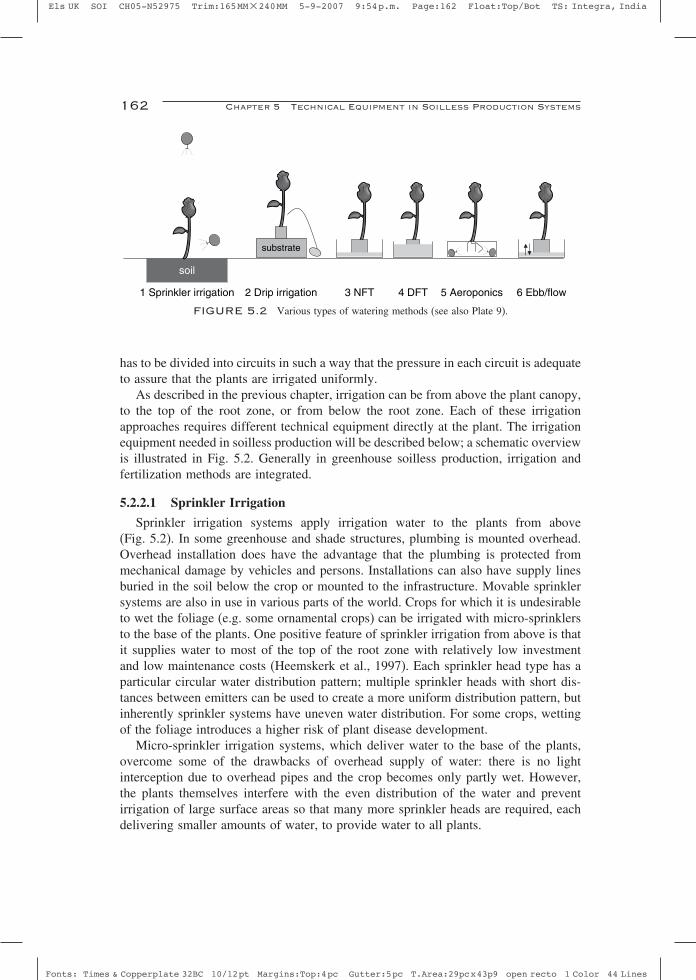
1 Sprinkler irrigation 2 Drip irrigation 3 NFT 4 DFT 5 Aeroponics 6 Ebb/flow
soil
substrate
FIGURE 5.2 Various types of watering methods (see also Plate 9).
has to be divided into circuits in such a way that the pressure in each circuit is adequateto assure that the plants are irrigated uniformly.
As described in the previous chapter, irrigation can be from above the plant canopy,to the top of the root zone, or from below the root zone. Each of these irrigationapproaches requires different technical equipment directly at the plant. The irrigationequipment needed in soilless production will be described below; a schematic overviewis illustrated in Fig. 5.2. Generally in greenhouse soilless production, irrigation andfertilization methods are integrated.
5.2.2.1 Sprinkler Irrigation
Sprinkler irrigation systems apply irrigation water to the plants from above(Fig. 5.2). In some greenhouse and shade structures, plumbing is mounted overhead.Overhead installation does have the advantage that the plumbing is protected frommechanical damage by vehicles and persons. Installations can also have supply linesburied in the soil below the crop or mounted to the infrastructure. Movable sprinklersystems are also in use in various parts of the world. Crops for which it is undesirableto wet the foliage (e.g. some ornamental crops) can be irrigated with micro-sprinklersto the base of the plants. One positive feature of sprinkler irrigation from above is thatit supplies water to most of the top of the root zone with relatively low investmentand low maintenance costs (Heemskerk et al., 1997). Each sprinkler head type has aparticular circular water distribution pattern; multiple sprinkler heads with short dis-tances between emitters can be used to create a more uniform distribution pattern, butinherently sprinkler systems have uneven water distribution. For some crops, wettingof the foliage introduces a higher risk of plant disease development.
Micro-sprinkler irrigation systems, which deliver water to the base of the plants,overcome some of the drawbacks of overhead supply of water: there is no lightinterception due to overhead pipes and the crop becomes only partly wet. However,the plants themselves interfere with the even distribution of the water and preventirrigation of large surface areas so that many more sprinkler heads are required, eachdelivering smaller amounts of water, to provide water to all plants.
Els UK SOI CH05-N52975 Trim:165MM×240MM 5-9-2007 9:54p.m. Page:163 Float:Top/Bot TS: Integra, India
Fonts: Times & Copperplate 32BC 10/12pt Margins:Top:4pc Gutter:5pc T.Area:29pcx43p9 open recto 1 Color 44 Lines
5.2 Water and Irrigation 163
Modern sprinkler installations are typically designed for the type of cropping systemand the specific demands of the grower. In outdoor nursery production, sprinkleremitters may include rotating impact sprinklers and gear-driven ones which throwa stream of water 2–20 m to ones with no moving parts which provide a circularspray pattern with a radius of 1–5 m. In greenhouse production, sprinkler systemsare less common and emitters are frequently micro-sprinklers which deliver water atlower rates with greater precision to the base of the plants. Emitters have also beendesigned with other features that improve performance; pressure compensation assuresthat emitters deliver water only while the pressure is between specified minimum andmaximum levels to avoid leaking of the emitters.
Due to the low expense of sprinkler systems relative to other systems, it is the mostwidely used system in outdoor container production. But even in these types of opera-tions, growers typically use sprinkler irrigation only with tightly spaced plants. Plantswhich are spaced far apart are typically irrigated with drip or micro-sprinkler systemsto reduce the amount of irrigation that misses the plants entirely. In greenhouse produc-tion, sprinkler irrigation is less commonly used due to the drawbacks mentioned above.
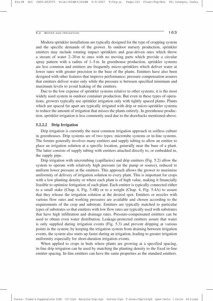
5.2.2.2 Drip Irrigation
Drip irrigation is currently the most common irrigation approach in soilless culturein greenhouses. Drip systems are of two types: microtube systems or in-line systems.The former generally involves many emitters and supply tubing to allow an emitter toplace an irrigation solution at a specific location, generally near the base of a plant.The latter consists of supply tubing with emitters attached directly to, or embedded in,the supply pipe.
Drip irrigation with microtubing (capillaries) and drip emitters (Fig. 5.2) allow thesystem to operate with relatively high pressure (at the pump or source), reduced touniform lower pressure at the emitters. This approach allows the grower to maximizeuniformity of delivery of irrigation solution to every plant. This is important for cropswith a low planting density or where each plant is of high value, making it financiallyfeasible to optimize fertigation of each plant. Each emitter is typically connected eitherto a small stake (Chap. 4, Fig. 5.4B) or to a weight (Chap. 4, Fig. 5.4A) to assurethat they release the irrigation solution at the desired spot. Emitters or nozzles withvarious flow rates and working pressures are available and chosen according to therequirements of the crop and substrate. Emitters are typically matched to particulartypes of substrates so that emitters with low flow rates are typically used with substratesthat have high infiltration and drainage rates. Pressure-compensated emitters can beused to obtain even water distribution. Leakage-protected emitters assure that wateris only supplied during irrigation events (Fig. 5.3) and prevent dripping at variouspoints in the system; by keeping the irrigation system from draining between irrigationevents, the system also starts up faster during an irrigation, leading to greater irrigationuniformity especially for short-duration irrigation events.
When applied to crops in beds where plants are growing at a specified spacing,in-line drip irrigation can be used by matching the planting density to the fixed in-lineemitter spacing. In-line emitters can have the same properties as the standard emitters.

Els UK SOI CH05-N52975 Trim:165MM×240MM 5-9-2007 9:54p.m. Page:164 Float:Top/Bot TS: Integra, India
Fonts: Times & Copperplate 32BC 10/12pt Margins:Top:4pc Gutter:5pc T.Area:29pcx43p9 open recto 1 Color 44 Lines
164 Chapter 5 Technical Equipment in Soilless Production Systems
FIGURE 5.3 Drip irrigation using pressure-compensated emitters to avoid leaking (see also Plate 10).
5.2.2.3 Nutrient Film Technique
Nutrient Film Technique (NFT) (Fig. 5.2) involves growing plants by maintaininga coating of nutrient solution around the roots, without the use of a substrate. WhenNFT first appeared, it seemed to be an ideal growing system because it seemed tooffer optimal control over the watering of the roots without the expense of a substrate(Cooper, 1979; Graves, 1983). Optimization schemes were difficult to develop so thattoday NFT is used only for a few specific crops. Technically most crops could begrown in an NFT system (examples amongst others: Morgan, 1985; Lataster et al.,1993; Ito, 1994; Hortiplan, 2005) but widespread adoption has not occurred probablybecause such systems lack the ability to buffer even the slightest interruption inwater and nutrient supply and there is a considerable risk of spreading root-bornediseases.
The system consists of a trough on a slope of 0.3–2 per cent; the roots of the plant lieinside the bottom of this trough. Nutrient solution is continually applied at the elevatedend, so that the solution flows down through the trough at exactly the rate required tokeep the roots completely wet. At the bottom end of the trough, the solution is allowed

Els UK SOI CH05-N52975 Trim:165MM×240MM 5-9-2007 9:54p.m. Page:165 Float:Top/Bot TS: Integra, India
Fonts: Times & Copperplate 32BC 10/12pt Margins:Top:4pc Gutter:5pc T.Area:29pcx43p9 open recto 1 Color 44 Lines
5.2 Water and Irrigation 165
to drain. The nutrient solution layer should be as thin as possible, almost as a film.The width of the trough varies according to the crop; troughs of 4–8 cm are sufficientfor crops such as lettuce and chrysanthemums, while for tomato and sweet pepper atrough of 15 cm is needed. The length of the trough varies from 1 to 20 m. Dependingon the crop and the sizes of the troughs, various types of materials have been used:polyethylene liner, polyvinylchloride (PVC), polypropylene and coated metal. Idealwater flow rates have been identified to be between 3 and 8 l m−2 h−1 for crops suchas chrysanthemums and lettuce (Benoit and Ceustermans, 1989b; Ruijs et al., 1990a,b;Benoit and Ceustermans, 1994). Fruiting vegetables benefit from a faster flow rate.The slowest flow rate that is adequate to keep the roots coated with water may notbe adequate in an NFT system; if the flow rate is too low, the problem is not lack ofwater, but lack of nutrients, especially for plants whose roots are downstream in thetrough and are exposed to water from which many other plants have already extractedsome nutrients. The last plants in the row get the least nutrients, especially potassium.Sometimes a distinction is made in flow rates needed for a young crop (2 l m−2 h−1)versus a mature crop (5 l m−2 h−1).
Plants destined for use in NFT systems are raised in small pots which are placedin the trough when a substantial root system has formed. In situations where the flowof water meanders in the trough, thus bypassing some plants, a lining of tissue inthe bottom of the trough can be used to minimize this problem (Van Os and Kuiken,1984). Shaped troughs (e.g. V-shaped) also prevent this problem (Formflex, 2005).
5.2.2.4 Deep Flow Technique
Deep Flow Technique (DFT) refers to a method that also attempts to keep theroots continuously exposed to moving water and nutrients. While with NFT the waterfilm is as thin as possible, with DFT the continuously flowing nutrient solution hasa depth of about 5–15 cm (Fig. 5.2). The large buffer of water and nutrients make itconsiderably simpler to control the nutrient solution. Only a relatively small fractionof the water and nutrients are actually taken up by the plants. The large volumeof water also buffers the temperature, making the system practical in regions wherenutrient solutions temperature fluctuations can be a problem (Ikeda, 1985; Ito, 1994;Park et al., 2001; Both, 2005). The width of the troughs in a DFT system are typicallyabout 100–130 cm. Plants are secured in holes on polystyrene panels by means ofa polyurethane foam; the panels float on the water or rest on the troughs sidewalls.The system is often installed at working height so that crops such as the lettuce orherbs can be easily planted and harvested.
5.2.2.5 Aeroponics and Aerohydroponics
In aeroponic growing systems the roots of plants are suspended in a volume whereemitters continually spray the roots with nutrient solution. The construction is similarto DFT (closed square box of about 1.2 m wide and 5–10 m long) but there is nowater layer; rather there is a constant misting of the roots. A similar enclosed space

Els UK SOI CH05-N52975 Trim:165MM×240MM 5-9-2007 9:54p.m. Page:166 Float:Top/Bot TS: Integra, India
Fonts: Times & Copperplate 32BC 10/12pt Margins:Top:4pc Gutter:5pc T.Area:29pcx43p9 open recto 1 Color 44 Lines
166 Chapter 5 Technical Equipment in Soilless Production Systems
FIGURE 5.4 Aeroponics, nutrient solution is divided by sprinklers (see also Plate 11).
is created in a triangle construct of polystyrene boards, as in a Japanese commercialdesign (Panel, 1988) and in a research arrangement (Leoni et al., 1994). In the triangleconstruct, the relative humidity is 100 per cent and oxygen availability is increasedaround the roots (Fig. 5.4). However, care should be taken that the upper plants receiveenough water. Often a thin layer of water is formed on the bottom, which acts as abuffer to the plants. Kratky (2005) showed the usefulness of the additional oxygenavailable in these systems by measuring higher lettuce yields in comparison to acontinuous water layer around the roots. The amount of water supplied to the plants isnot mentioned in the literature; often a timer is used, but the release rate of the nozzleis not given. Ruijs et al. (1990b) suggest a flow rate of 2 l m−2 h−1 for chrysanthemumcrops.
The NFT and aeroponic systems share the disadvantages due to lack of a bufferaround the roots for water, nutrients and heat. A hybrid system was devised by Sofferand Levinger (1980) by combining aeroponics with DFT, which they called ‘The EinGedi System’ and coined the term ‘aerohydroponics’ for it. Here the roots of theplants extend through a panel, dangling in an airspace as with aeroponics, but into asubstantial quantity of flowing nutrient solution, rather than just a thin film. One facetof this system is that the nutrient solution is continuously aerated and the rate at whichthe bulk flow of water and nutrients bathes the roots exceeds that of any other soillessproduction system.
With all variations of aeroponics, electricity is used to achieve all the bulk movementof water and this movement is critical to the survival of the plants. Evaluation of thecommercial feasibility of such system requires balancing this energy cost with theenhancements in nutrient uptake and oxygen availability.

Els UK SOI CH05-N52975 Trim:165MM×240MM 5-9-2007 9:54p.m. Page:167 Float:Top/Bot TS: Integra, India
Fonts: Times & Copperplate 32BC 10/12pt Margins:Top:4pc Gutter:5pc T.Area:29pcx43p9 open recto 1 Color 44 Lines
5.2 Water and Irrigation 167
FIGURE 5.5 Ebb and flow on a concrete floor for foliage plants (see also Plate 12).
5.2.2.6 Ebb and Flow/Ebb and Flood
In ‘Ebb and Flow’ or ‘Ebb and Flood’ systems (EF), container-grown plants areflood-irrigated on a water-tight tray or floor. During irrigation, water flows onto thetray or floor so that the base of each pot is submerged as the tray or floor is flooded(Fig. 5.5). The required duration of the flooding depends on the hydraulic conductivityof the substrate in the containers. The duration should be adequate to allow the waterwithin the root zone to be wicked to the top of the root zone: generally 10–30 minif the substrate has high unsaturated hydraulic conductivity (longer if not). Then thetray or floor is drained which also allows the substrate to drain. Sloping surfacesand drainage grooves or channels are engineered into these systems to maximize theuniformity in water contents across a floor or tray between all pot/containers whilefacilitating rapid drainage. It is particularly important that the water be allowed todrain away completely so as to prevent root diseases. If wet spots remain around theplant, algae growth, root diseases and uneven watering will occur.
5.2.3 FERTIGATION HARDWARE
Water serves two important functions in plant production: it provides a vital resourcefor growth and also acts as a transport system for nutrients. Irrigation practices whereboth of these functions are actively combined in one system through the use of

Els UK SOI CH05-N52975 Trim:165MM×240MM 5-9-2007 9:54p.m. Page:168 Float:Top/Bot TS: Integra, India
Fonts: Times & Copperplate 32BC 10/12pt Margins:Top:4pc Gutter:5pc T.Area:29pcx43p9 open recto 1 Color 44 Lines
168 Chapter 5 Technical Equipment in Soilless Production Systems
Cleanwaterbasin
Diluter
Chemicalstocksolutes
Greenhousewith plants
Disinfectionunit
Disinfecteddrain storage
Drainstoragetank
Drain pit
1 2 8
FIGURE 5.6 Schematic overview of the nutrient solutions way in a closed production system. Thediluter/dispenser unit sees to it that concentrated fertilizers are diluted to a nutrient solution to be taken upby the plant.
completely soluble fertilizers are called fertigation. In this section, we focus on thedynamic control of the supply of nutrients in fertigation systems.
A diluter/dispenser unit combines nutrients as concentrated chemical solutes inAU2
two to eight stock tanks (Fig. 5.6) with irrigation water. A system of pumps, valvesand irrigation capillaries delivers the resulting nutrient solution to each individualplant.
The amount of irrigation is often controlled by time-duration operation of the supplyor by a sequence of a controlled number of equal volumetric additions. Valves connectthe nutrient diluter/dispenser unit to the various irrigation sections of the greenhouse.Approximately, 50 section valves can be allocated flexibly; each section is equippedwith instruments to measure and log the amount of supply and drainage and dailyaverages of EC, pH and water usage.
Supporting programs manage the rainwater stock storage tanks or basins, thedrainage storage and the storage for cleaned drain water. When additional water isneeded in the system, selection criteria determine the source of the clean water. Sinceclean water is a highly valuable resource, water from different sources should not bemixed beforehand.
In closed growing systems the drainage water is recycled. Precipitation of crys-tallized salts may occur when highly concentrated stock fertilizer are directly mixedwith the water from the drainage tanks. The recycled drainage water will be mixedwith fresh water in a proportion selected to achieve a pre-defined EC value of theinput water to the diluter/dispenser unit. An accurate control of the EC and pH ofthis input water should be incorporated into the unit’s controller, in combination withprocedures for automatic cleansing of filters in the recirculation circuit. Comprehen-sive and detailed fertigation management should include these techniques to preventfailures due to unexpected EC and pH values or blockages in the system due toprecipitation.

Els UK SOI CH05-N52975 Trim:165MM×240MM 5-9-2007 9:54p.m. Page:169 Float:Top/Bot TS: Integra, India
Fonts: Times & Copperplate 32BC 10/12pt Margins:Top:4pc Gutter:5pc T.Area:29pcx43p9 open recto 1 Color 44 Lines
5.2 Water and Irrigation 169
5.2.3.1 Sensors and Measurement
Electrical conductivity and pH
The EC and pH sensors are the simplest form of direct measurement in elec-trolyte solutions and are basic instruments for any grower using soilless productionsystems.
The EC sensors that are used in equipment for the processing of fertilizers measureusing three equidistant ring-shaped electrodes which are mounted inside the watertransport pipe at equal distances. The two end-electrodes are connected to each otherand to ground. The temperature of the fluid is measured and is used to modify thevalue of the alternating current (AC) voltage applied between the central electrodeand the ground electrodes as a means of temperature compensation. This AC voltageis typically around 1 V. The AC frequency that may range from 400 Hz to 50 kHzAC voltage is used to avoid polarization of the electrodes. The EC is determinedby dividing the AC voltage by the electric current measured between the centralelectrode and the two end-electrodes. The current ranges from 0.1 to 10 mA. Both end-electrodes are connected to each other and to the electrical ground terminal to allowthe serial or parallel connection of several EC electrodes in one water supply system.In horticultural practice, two distinct EC electrodes are used in parallel to provide acheck on the functioning of both EC sensors against each other. The measuring rangeof an EC sensor is between 0 and 10 [dS m−1].
The pH of a solution indicates how acidic or basic (alkaline) it is. The pH sensormeasures the potential across a thin glass bulb or membrane caused by the differencein activity of H3O+ ions (protons) in the electrolyte on one side of the membraneand the measurant on the other side. In fertigation equipment, pH is measured witha standard combination type of sensor and includes a measuring electrode and a ref-erence electrode in the same sensor body. A gel is used as an electrolyte, whichmeans that the electrolyte needs no further replenishing. In this way, the slow dete-rioration of the pH sensor is avoided. The lifetime expectancy of these pH sensorsis about one year. Again, two sensors can be used, so that one sensor is checkedagainst the other. The values obtained with the EC and pH sensors are comparedwith the results of a bi-weekly laboratory analysis as an additional check. The lab-oratory analysis is also used for determination of the composition of the nutrientsolution.
Sensors for individual ions
An Ion-selective Electrode (ISE) is a sensor which converts the activity of a specificion dissolved in a solution into an electrical potential which can be measured by avoltmeter (Fig. 5.7). The voltage is theoretically dependent on the logarithm of the AU3
ionic activity, according to the Nernst equation (Chang, 1990). The sensing part ofthe electrode is usually made as an ion-specific membrane, along with a referenceelectrode. ISEs are used to measure on-line the activity of cations and anions in theroot environment. ISE sensors are available for most macro-nutrients, like K+, Ca2+,NO3
−, SO42−, NH+
4 and for Na+ and Cl−.

Els UK SOI CH05-N52975 Trim:165MM×240MM 5-9-2007 9:54p.m. Page:170 Float:Top/Bot TS: Integra, India
Fonts: Times & Copperplate 32BC 10/12pt Margins:Top:4pc Gutter:5pc T.Area:29pcx43p9 open recto 1 Color 44 Lines
170 Chapter 5 Technical Equipment in Soilless Production Systems
IonselectiveElectrode
ISE referenceelectrode
Capillary
Electrolyte
Membrane
FIGURE 5.7 Basic principle of an Ion-selective Electrode.
Soil or substrate moisture
Close monitoring of soil or substrate moisture may be useful to maintain an efficientgrowth and to protect the environment. Waste of valuable nutrients and pollution of thesurrounding environment, if open growing systems are used, is caused by the practiceof providing a slight overdose of nutrient solution (10–50 per cent) and letting theexcess solution run off as drainage water to wash out unused nutrients from the growingmedium. Closed growing systems solve this problem by catching and recycling thedrainage water.
The moisture content of the growing medium is an important variable in the uptakeof water.
Sensors to measure water content determine the dielectric properties or the hydraulicproperties of the growing medium, or the change of weight of the growing medium isestablished.
Dielectric sensors
Dielectric methods to determine water content from the dielectric constant of thesubstrate are rapidly gaining ground. The relationship between the dielectric constantfor each specific soil type and its water content has to be established in a calibrationprocedure.
In time domain reflectometry (TDR), a short electrical pulse is sent into a pair ofelectrodes and the time-dependent reflected signal is analysed to give the water contentof the medium between the electrodes. TDR equipment is commercially available. Thebasic principle of dielectric sensor operation is described in detail in Chap. 3.
In an alternative approach, the real and imaginary part of the complex impedancebetween two electrode needles is measured at one carefully chosen (high) frequency(Hilhorst et al., 1992). This Frequency Domain (FD) Method allows calculation ofAU4
both water content and EC and is easier to automate and miniaturize than TDR.A commercial version is available as a sensor for Water content of the substrate, EC ofthe substrate and Temperature of the substrate (the so-called WET sensor, Balendoncket al., 1998; Delta-T, 2006). Special designs of the two electrodes of the FD sensor

Els UK SOI CH05-N52975 Trim:165MM×240MM 5-9-2007 9:54p.m. Page:171 Float:Top/Bot TS: Integra, India
Fonts: Times & Copperplate 32BC 10/12pt Margins:Top:4pc Gutter:5pc T.Area:29pcx43p9 open recto 1 Color 44 Lines
5.2 Water and Irrigation 171
offer opportunities to build sensors with one electrode rod (Balendonck et al., 1998;Delta-T, 2006). FD sensors are commercially available.
Hydraulic tensiometer
A porous cup filled with distilled water can be used for water potential levelsnear zero. When the cup is brought in contact with the growing medium, equilibriumwill develop in which the pressure inside the cup equals the suction of the soil orthe substrate (Slavik, 1974). The pressure inside the cup is measured with a pressure AU5
transducer. The basic principle of tensiometer operation is described in detail inChap. 3.
The method works for suction pressures as low as −80 kPa. At lower pressures,there is a risk of air entering the cup. Errors will arise when contact between cup andsoil is lost. Hydraulic tensiometers are commercially available. For more informationon tensiometers in soilless production, see Chap. 4.
Gravimetric sensing
Changes in plant weight can also be sensed so that this input can be used as partof irrigation control. One example is shown in Fig. 5.8 where metal trough withapproximately 16 plants (to give a representative sampling) is suspended from thegreenhouse frame by wires. The wires are connected to load cells. An extra set ofload cells measures the change of the fresh weight of the plants (Fig. 5.8). The weightchanges are due to growth, supply of nutrient solution, the run-off of drainage water,the free evaporation of water and the transpiration of the plants. The change of weightdue to growth, evaporation or transpiration is slow and over short time periods itshows itself as an almost steady signal.
The amount of supplied nutrient solution is determined by detecting the suddenchange in weight when the supply is started. The exact increase in weight from thatmoment on till the end of supply is the accurate measuring signal for the suppliedamount.
The drainage water is collected in a small break-out tank (∼50 mL), which is fixedto the through. The tank discharges when a fixed level is reached in the break-outtank. The sudden discharge of the collected drainage by the break-out tank is detectedby the sudden change in the overall weight signal of the load cells. The exact decreasein weight from that moment till the end of the discharge is the accurate measuringsignal for the amount of drainage water.
On the basis of this precise information, the supply of nutrient solution can becontrolled with high accuracy. The change of the fresh weight of the plants and thevalue of the transpiration are used to inform the grower about the status of his crop.The basic principles of gravimetric sensing and examples for its use are described indetail in Chap. 3.

Els UK SOI CH05-N52975 Trim:165MM×240MM 5-9-2007 9:54p.m. Page:172 Float:Top/Bot TS: Integra, India
Fonts: Times & Copperplate 32BC 10/12pt Margins:Top:4pc Gutter:5pc T.Area:29pcx43p9 open recto 1 Color 44 Lines
172 Chapter 5 Technical Equipment in Soilless Production Systems
Metalgully
Draincollector
Inflow
LD
45
mL
Outflow
FIGURE 5.8 Measuring trough: by measuring the weight of the plants and the trough and the incomingwater supply and outgoing leaching part, there is exact knowledge about the quantity of nutrient solution tobe dosed to the plant at exactly the right moment.
5.2.3.2 Stock Solutions: A and B Solutions Versus IndividualLiquid Fertilizers
A specific recipe of nutrients can be made for the particular crop in relation tothe chemical composition of the source water. In 1970, when hydroponic productionwas introduced in The Netherlands, a system was developed by Verwer (1978) withone central tank to hold irrigation solution created by combining water with two stocksolutions, called A and B solutions.
This type of system is still in widespread use today. The two stock solutions areprepared at concentrations 100 or 200 times higher than the average concentration ofthe solution to be supplied to the plants. Tank A contains all calcium compounds.In container B, all sulphates and phosphates are dissolved (Fig. 5.9). If the fertilizers inthe two stock solutions were to be mixed at these concentrations, precipitation wouldoccur in the pipes, valves and emitters, with disastrous results. For these reasons,solutes from the A and B tanks are diluted in fresh water in the mixing tank to achievethe right concentration and the appropriate EC level of the nutrient solution. An extraamount of an acid or base solute may be used to control pH of the batch of nutrientsolution in the mixing tank.

Els UK SOI CH05-N52975 Trim:165MM×240MM 5-9-2007 9:54p.m. Page:173 Float:Top/Bot TS: Integra, India
Fonts: Times & Copperplate 32BC 10/12pt Margins:Top:4pc Gutter:5pc T.Area:29pcx43p9 open recto 1 Color 44 Lines
5.2 Water and Irrigation 173
Mixing container
Freshwater
Drainwater
A B
Base
Acid
pH
EC
pHEC
Venturisystem
FIGURE 5.9 Example of a fertilizer diluter/dispenser unit where a Venturi fitting in the main supplypipe creates a pressure drop to transport concentrated fertilizers (courtesy Priva bv, De Lier, Netherlands).
The recipe of the A and B mixtures is selected according to the requirements ofthe crop to be fertigated and is based on a laboratory analysis performed every twoweeks. Fertilizers are usually added to the A and B tanks by hand. This is heavy andunpleasant work, especially when the size of the greenhouse is in the range of severalhectares. This is one reason for finding new methods to fill the concentrated fertilizertanks.
One option is to deliver individual liquid fertilizers by tanker from a supplier. Ingeneral, depending on the supplying company, 6–10 liquid fertilizers are combinedin a standard recipe for most commercial greenhouse crops. The tanker is equippedwith separated segments, one segment for each concentrated fertilizer. A standardizeddischarge procedure ensures that each chemical fluid ends up in the right container,thus minimizing the chance of accidents. The need for additional manual labour iseliminated. However, significant disadvantages of this method are the cost for thetransportation. Since a large quantity of water is transported, costs increase. The tankermethod is only of particular interest in areas of greenhouse concentration, such asthe Westland area in The Netherlands, the Almería region in Spain or the Brittanyregion in France. However, for most greenhouse production regions, it will be tooexpensive.
A second option is to manually mix solid fertilizers in the A and B stock tanks from25 kg bags with standard fixed mixtures. The amount of labour can be decreased bythe use of large plastic bags of 1 or 2 m3, where the solid fertilizers are pre-mixed bythe supplier in an A bag and a B bag, in accordance to the latest laboratory analysis.The bags are delivered on standard pallets, placed on a platform above the A and Btanks by a fork lift truck and easily emptied through an opening at the bottom of thebag. The whole content of the big bags is used at once.
New recipes of the A and B stock solution are prepared sequentially, but the releaseof the new recipe in both stock tanks is done at the same time to ensure that changesin the composition of the A and B solutions happen at the same time.

Els UK SOI CH05-N52975 Trim:165MM×240MM 5-9-2007 9:54p.m. Page:174 Float:Top/Bot TS: Integra, India
Fonts: Times & Copperplate 32BC 10/12pt Margins:Top:4pc Gutter:5pc T.Area:29pcx43p9 open recto 1 Color 44 Lines
174 Chapter 5 Technical Equipment in Soilless Production Systems
The recipe of the nutrient solution must be adapted to the needs of the crop duringthe development of the plant from a seedling stage to a reproductive stage. Cultivationstarts with a species-related standard recipe. This recipe is then adjusted in accordancewith advice from a specialized laboratory after a test performed every two weeks on asample taken from the root environment. The advice takes into account the compositionof the different stock nutrients, whether they are solid or liquid stock fertilizers andinformation about the status of the crop. The appropriate adjustments to the recipeare calculated on the basis of this information. Not all the possible outcomes of thesecalculations result in recipes that the diluter/dispenser unit is capable of producing.During recent years, fertilizers have evolved from simple single- or multi elementfertilizers to more sophisticated combinations of elements, fine-tuned for a specificgrowth strategy. In liquid fertilizers, the option of adjusting pH levels has also beenintroduced (Fig. 5.10) by adding acid or basic fertilizer solutions. Manual calculation ofthe recipe has been replaced by computerized calculation, which has made it possible totake all kinds of constraints into account. Nowadays these algorithms are also directlyavailable to the grower as a spreadsheet or as a specialized calculation program relatedto a particular brand of fertilizer. Certain mixtures may lead to precipitation or tocombinations of ions that cannot be produced from the available fertilizer stock solidsor stock solutes. If the dilutor/dispenser units should be forced to proceed with an
Individual nutrients
Ca(NO3)2Micro
nutrientsNH4NO3 KH2NO3KH2NO3 MgSO4 K2SO4 KNO3
pH
pH ECpH EC
EC
6
1
F
3
8 9
5
7
2
6. stock tanks7. retarder mixer
1. drain container2. water from basin
8. sand filter9. fine filter
3. system pump
5. flow sensor4. metering pump
5
4
FF F F F F F
FIGURE 5.10 System with metering pumps to supply the stock liquids directly into the main supplyline or into an open non-pressurized mixing tank.

Els UK SOI CH05-N52975 Trim:165MM×240MM 5-9-2007 9:54p.m. Page:175 Float:Top/Bot TS: Integra, India
Fonts: Times & Copperplate 32BC 10/12pt Margins:Top:4pc Gutter:5pc T.Area:29pcx43p9 open recto 1 Color 44 Lines
5.2 Water and Irrigation 175
‘impossible recipe’, it can cause precipitations, blockages in the transport conduits oreven explosions (Schrevens and Cornel, 1990). Additionally, optimization algorithmsmay on occasion lead to a more cost-effective choice of similar fertilizers.
5.2.3.3 Commercial Injector Systems for the Dilutionof Concentrated Fertilizers
The mixing tank system
The operating principles of mixing tank diluters are as follows: A mixing tankis connected to the various fertilizer stock tanks (Fig. 5.9). In these storage tanks,solid fertilizers are dissolved in water and diluted at a standard high concentration.Quantities of the highly concentrated fertilizer solutions are fed into the tank of thenutrient dispenser system. They are mixed in accordance with a recipe, diluted withfresh water to a suitable concentration for the plants and finally pumped to the cropin the greenhouse.
There are several ways of feeding the highly concentrated stock mixtures into themixing tank:
• Metering pumps supply the stock liquids into an open non-pressurized mixingtank or directly into the main supply line. One batch is prepared at a time in themixing tank and then pumped to the greenhouse (Figs. 5.9 and 5.10). Examplesof these systems are found in the early designs of computerized nutrientfertilizer systems (Bauerle et al., 1988; Papadopoulos and Liburdi, 1989).
• A Venturi fitting inside the main supply line creates a pressure drop whichforces the stock fertilizers (Fig. 5.9) into the mixing tank or into pre-mixingchambers.
• Small container tubes (∼5 L) are placed just above a mixing tank, one tube foreach concentrated stock solution (Fig. 5.11). A valve at the bottom of the tubereleases a precise quantity of stock solution into the mixing tank. A pressuresensor in the bottom of the tube measures the amount of stock solutionreleased. The container tubes are filled by means of simple pumps or gravity(the stock tanks are in an elevated position).
The EC of the supply solution is controlled by altering the extent of the dilution ofnutrients and water. The simplest systems are laid out to mix a small number of stocksolutions, such as systems where four nutrient stock fertilizers are used with an extraacid or base solution for pH correction. EC- and pH-sensors are installed in duplicateto ensure safe operation. An embedded computer system controls the mixing process,the alarms and operator communication.
Mixing tank dispensers are used in systems with overhead sprinklers, drip irrigationsystems or in ebb-flow systems. They are configurable for both in-line as well as inbatched by-pass mode. The systems are available for various output capacities in therange of 1 m3 h−1 to more than 40 m3 h−1. A small number (4–6) of different nutrientrecipes is possible. The EC set value is dependent on changes in global radiation.

Els UK SOI CH05-N52975 Trim:165MM×240MM 5-9-2007 9:54p.m. Page:176 Float:Top/Bot TS: Integra, India
Fonts: Times & Copperplate 32BC 10/12pt Margins:Top:4pc Gutter:5pc T.Area:29pcx43p9 open recto 1 Color 44 Lines
176 Chapter 5 Technical Equipment in Soilless Production Systems
FIGURE 5.11 Small container tubes (∼5 L) are placed just above a mixing tank to precisely releasea quantity of stock solution into the mixing tank.
Direct injection system
The injection of concentrated fertilizers by means of a pressure drop in the mainsupply line is a modern and attractive alternative to the use of metering pumps. Thepressure drop is created across a Venturi (Fig. 5.9). This pressure drop is the drivingforce to suck in the concentrated fertilizer fluids. It is a compact means of fertilizertransport, using fewer devices and moving parts that require maintenance, than asystem with metering pumps. Direct injection diluter/dispenser units are available inseveral sizes and capacities.
Simple direct injection systems use a mixing tank to mix and dilute the stockfertilizers from the A and B tanks by using separate pre-mixing chambers into whichthe highly concentrated solutions of stock fertilizers are combined with supply water.This solution is then injected into the main supply line, where it is diluted to theconcentration that is needed for the plants.
Systems that blend and dilute highly concentrated stock solutions of individualliquid fertilizers are more complex. The dispenser unit uses a fertilizer channel for eachstock tank. A Venturi pressure drop in the main supply line is again the driving forcebehind the movement of the concentrated fertilizer fluids. The channel is closed offwith a small ceramic insert with an orifice. The orifice ensures a fixed and limited flowrate. Ceramic inserts with different orifice sizes are used for the different channels.A flow meter and a fast-switching valve control precisely the accumulated flow overtime. Four channels are connected to the mixing chamber. The amount of fertilizertransported into the mixing chamber is determined by the pulse activating the valves.

Els UK SOI CH05-N52975 Trim:165MM×240MM 5-9-2007 9:54p.m. Page:177 Float:Top/Bot TS: Integra, India
Fonts: Times & Copperplate 32BC 10/12pt Margins:Top:4pc Gutter:5pc T.Area:29pcx43p9 open recto 1 Color 44 Lines
5.2 Water and Irrigation 177
FIGURE 5.12 More sophisticated direct injection system for single element liquid fertilizers (see alsoPlate 13; courtesy Priva bv, De Lier, Netherlands).
A static retarder in the main supply line mixes the highly concentrated fertilizers withthe supply water (Fig. 5.12) and prevents the contact of hazardous combinations ofhighly concentrated stock fertilizers with residues of nutrient ions in the supply water(recirculated in case of closed systems).
The process of mixing and diluting the various individual fertilizers is controlled byfeeding back the measured EC value of the supply water into a computer controller.The amount of each individual fertilizer is calculated and corrected by the controller asa function of the measured water supply flow rate and the volumetric relation betweenthe various fertilizers, as prescribed in the recipe selected by the grower. The intendedpH and EC will be realized in the solution when the mixing algorithm is correctlyapplied. However, other factors, such as small changes in the composition of the cleaninput water of the system or the use of recirculated drainage water, introduce the needfor fine-tuning the pH and EC value. This is carried out automatically by adjusting theoutput of the appropriate individual fertilizer channel in relation to its recipe value. Anexcess of a particular nutrient ion can be corrected in the next fertilizer supply cycle.
The concentration of the individual stock solutions is used as an input parameterin the calculation of the fertilizer recipes. The system is thus easily adjusted toaccommodate all available concentrations of stock solution, such as standard industrialsolutions or special stock solutions prepared for horticulture. Durable materials and asmall number of moving parts ensure intrinsic reliability.
In general, eight liquid fertilizer fluids are sufficient to realize every possiblerecipe, including one channel for micro-nutrients. Injection dispensers are available ata capacity in the range of 100 m3 h−1.

Els UK SOI CH05-N52975 Trim:165MM×240MM 5-9-2007 9:54p.m. Page:178 Float:Top/Bot TS: Integra, India
Fonts: Times & Copperplate 32BC 10/12pt Margins:Top:4pc Gutter:5pc T.Area:29pcx43p9 open recto 1 Color 44 Lines
178 Chapter 5 Technical Equipment in Soilless Production Systems
Safety and protection
Mixing highly concentrated ionic nutrient liquids can be hazardous. Extra precau-tions must be built into the system to protect the grower and his staff from hazardoussituations. For this purpose, extra sensors should check the process of dilution, mixingand dispensing for potential hazards, such as
• excessive or insufficient flow in the individual fertilizer channels;• liquid fertilizer leakages;• intake of air into the fertilizer mixing channels;• unexpected drop in capacity;• jamming of the channel.
General checks on the following should also be made:
• sudden or large deviations from the expected EC and pH values;• leakage from the stock tanks (also when the equipment is switched off);• the stock tanks should be stored in a containment pool with the capacity of at
least one stock tank.
5.3 PRODUCTION SYSTEMS
Since the advent of the use of soilless culture, various types of production systemshave been developed to produce specific crops. In general, crops grown this way are‘high-value’ crops that have a high rate of economic return, thus ensuring that thedeployed inputs-intensive system is profitable for the grower. Initial phases of thisindustry involved production in the ground in highly amended soils with above-groundsoilless systems being a more recent development. In soilless production today, somesystems sit directly on the ground, while others are raised above ground, allowing forno connection between plants and soil.
For each of these types of production systems, we will discuss the advantages anddisadvantages, and the suitability for specific groups of crops (crops in rows, crops inbeds). Substrates will not be discussed in this section, although a distinction will bemade between solid substrates (such as stone wool or polyurethane slabs), granulatedsubstrates (such as perlite, pumice, coir or peat) and no substrate (as in NFT andaeroponics). Most systems can be either open (all leachate flows into the subsoilwithout recirculation) or closed (leachate is reused).
5.3.1 SYSTEMS ON THE GROUND
5.3.1.1 Ground Preparation
Ground preparation is extremely important when installing a production system thatwill be placed directly on the ground, so as to minimize the incidence of pathogens

Els UK SOI CH05-N52975 Trim:165MM×240MM 5-9-2007 9:54p.m. Page:179 Float:Top/Bot TS: Integra, India
Fonts: Times & Copperplate 32BC 10/12pt Margins:Top:4pc Gutter:5pc T.Area:29pcx43p9 open recto 1 Color 44 Lines
5.3 Production Systems 179
and weeds. Steam sterilization, a chemical treatment or a solarization treatment can beused to ensure a disease-free start and to prevent the germination of weeds. Treatmentof the top 10 cm of soil is generally sufficient. Production systems which sit directlyon the ground also require that the ground be prepared to accommodate the hydraulicneeds of the system so that the drainage water from the production system is managedcorrectly. Wet and dry areas will develop if the root zone is not perfectly horizontal oron an even incline. Consequently, water availability for the plants will not be uniformresulting in oxygen deficiency in some pockets, leading to root rot. Deviations fromthis may also lead to variations in EC levels, leading to reduced productivity andquality.
Levelling is mostly done at a slope of 0.3 to 0.5 per cent along the length of thegreenhouse span. The overall length is subdivided into sections of 20–25 m to avoidexcessive differences in height within the greenhouse. A moulding machine can beused to adequately shape the subsoil after levelling. The substrate bed that will makeup the root zone may be lower or higher than the aisle and small canals are dug fordrain water collecting tubes. Shaping by hand is impractical for larger areas, and theaccuracy of the work is likely to be inadequate. Compaction of the soil may also beneeded in cases where the production system is heavy.
A plastic barrier between the production system and the ground is generally usedto manage weeds and excess moisture. This can take the form of a plastic film ordurable woven material with a tight mesh. Selection of a liner made of a light-colouredmaterial provides the feature that it reflects light back up towards the plants. This isespecially important in latitudes with prolonged dark periods and short daylight periods.A disadvantage of a light-coloured (white) material is that it generally allows enoughlight to penetrate into and through the material to allow for some weed germinationand UV degradation of the plastic. A black liner may be more advantageous thana white liner in areas where it is of greater value to have the ground below theliner attain slightly higher temperatures (cold greenhouses without possibilities to heatduring the night) since it will store more heat during the day and release it duringthe night. A dark material is also generally more resistant to the degrading effects ofUV radiation. Additionally, a liner prevents the movement of plant diseases from theground into the production system.
Woven material, rather than impervious film, should be used in cases where waterneeds to seep into the ground below the aisle and production system. In such cases,the ground preparation should be such as to avoid excessive compaction of the groundwhere the aisle will be located.
There is a significant difference in the type of layout of plants within ground-basedsystems. Some production systems consist of long rows of individual plants spaced atsome particular spacing (i.e. ‘single rows’). Other systems consist of rows of plantswith several plants side by side (i.e. a ‘bed’ of plants). In this chapter, we define‘single row’ to be a row of individual plants in a substrate and/or trough forming aroot zone that is 4–25 cm wide. On the other hand, a ‘bed’ is defined as consisting ofseveral plants growing side by side in wider arrangement (>1 m) with the root zone AU6
completely filled with substrate.

Els UK SOI CH05-N52975 Trim:165MM×240MM 5-9-2007 9:54p.m. Page:180 Float:Top/Bot TS: Integra, India
Fonts: Times & Copperplate 32BC 10/12pt Margins:Top:4pc Gutter:5pc T.Area:29pcx43p9 open recto 1 Color 44 Lines
180 Chapter 5 Technical Equipment in Soilless Production Systems
5.3.1.2 Crops in Single Rows
Single row systems are in use for crops such as roses, cucumber, tomato, pepper,strawberry and lettuce (Benoit and Ceustermans, 1989a). For crops in narrow rows,small quantities of substrates are normally used during propagation in the form ofpressed peat pots or plugs. Propagules are started in these, from either seed or cuttings,and later transferred to a production system. Many times, single row systems are placedso that two single rows are adjacent (forming pairs of rows); this is done when the widthof a single row is such that harvesting and plant management can be accomplishedfrom one side of the row. This effectively eliminates a large percentage of aisle space,resulting in greater overall production efficiency.
Generally, the soilless substrate that makes up the root zone of plants grown insingle rows is enveloped in plastic film so as to contain the irrigation water. Preformedmaterials, such as stone wool slabs, as well as some granulated substrates are generallyenclosed in bags which have adequate support to allow them to be placed directly ontop of the liner without the need for a reinforcing container. Substrate products whichare not in these forms require some physical containment to hold the root zone in itsdesired form. This is either in the form of nursery containers, buckets or troughs.
Production systems which are placed directly on the ground are generally moredifficult to configure as closed systems. In an open system, drainage water seepsdirectly from the root zone through the liner into the ground below the crop (Fig. 5.13).This traditional approach has the benefit that the required investment in materials islow, but a lot of water and fertilizer is wasted while also polluting the environment.Governmental regulations in most of Europe and North America now control thepermitted amount of nitrate leaching (Agricultural Structure Memorandum, 1989;National Environmental Policy Plan, 1989) so that open systems are being phased outin many such areas. This has accelerated the development towards closed systems.
10–20 cm
Aisle, 70–90 cm1
1: substrate slab or granulated substrate2: foil around the substrate3: drain holes are made 1–2 cm above ground level and at the non-aisle side4: drip irrigation at the non-aisle side5: pots for plant raising, using the same substrate6: plastic liner covering the soil
23
4 5
6
FIGURE 5.13 Open systems for single row crops.

Els UK SOI CH05-N52975 Trim:165MM×240MM 5-9-2007 9:54p.m. Page:181 Float:Top/Bot TS: Integra, India
Fonts: Times & Copperplate 32BC 10/12pt Margins:Top:4pc Gutter:5pc T.Area:29pcx43p9 open recto 1 Color 44 Lines
5.3 Production Systems 181
1
2
3
76
54
98
1: U-shaped trough2: film with drain pipe3: double row with foil and drain pipe4: metal trough with two drain gutters5: trough with drain gutter6: PVC trough with drain gutter7: flexible polypropene profile8: plateau trough with gutters for irrigation and drain9: suspended trough
FIGURE 5.14 Troughs and profiles for closed single row systems.
A variety of materials have been used to create the troughs that collects the drainagewater from slabs and bags (Lataster et al., 1993): plastic film, with or without inte-grated drain pipe, U-shaped polypropylene troughs, V-profiles and PVC profiles, metaltroughs (Fig. 5.14).
One of the least expensive closed systems consists of a plastic bag or film wrappedaround a substrate slab with collection pockets on one side. Often a drain pipe is laidinto the channel along the length of the row to keep the drainage channel open.
Plastic sheeting material consisting of polypropylene or polyethylene, 1–2 mm thick,delivered in rolls, can be used to create a system of drainage troughs. These aretypically 15–25 cm wide and have vertical edges 5 cm high. The bottom can be flator V-shaped. The system requires careful levelling and compaction of the ground toprevent depressions where water can stagnate. Recirculation of the nutrient solution tothe water treatment unit is easy because special fittings interconnect the troughs andthe main pipeline.
Troughs have also been made of polyvinyl chloride (PVC), but such systems aremuch less flexible. This material is brought in its final shape from the factory and,consequently, cannot be delivered in roll form to the greenhouse for production of thetrough on the spot. Lengths of 6–12 m have to be assembled at the greenhouse intothe desired configuration. There is a risk of breakage.
Metal troughs can also be created either through shaping on-site off of large rolls(with a machine) or from preshaped trough segments. While expense may be a decidingfactor as to whether plastic of metal needs to be used, it is important to note that somesubsoil may not have adequate support for a plastic system, so that the stronger metalsystems are needed so as to prevent breakage and reduce sagging.

Els UK SOI CH05-N52975 Trim:165MM×240MM 5-9-2007 9:54p.m. Page:182 Float:Top/Bot TS: Integra, India
Fonts: Times & Copperplate 32BC 10/12pt Margins:Top:4pc Gutter:5pc T.Area:29pcx43p9 open recto 1 Color 44 Lines
182 Chapter 5 Technical Equipment in Soilless Production Systems
One consideration when selecting a material for drainage troughs is the need todisinfect the troughs between crops. If steam or hot water is applied to a trough madeof thin plastic, then the trough is likely to deform. Solarization of these materials ispossible, but temperatures must reach at least 70�C, and this is obviously dependent onthe prevailing weather conditions. PVC has the added disadvantage that burning duringdisposal releases chlorine into the atmosphere and is therefore prohibited in manycountries, while polyethylene and polypropylene can be burned completely withoutintroducing too much pollution.
A system consisting of both a metal trough and a plastic film may be needed insituations where the structure of the soil of the ground is such that it results in saggingof a production system installed directly on the ground. Coated metal troughs areavailable in many widths and shapes (Formflex, 2005, Fig. 5.15) and can be placeddirectly on the ground or above the ground and even as movable systems (as describedbelow). A metal trough system is typically more expensive than a plastic trough, butit is less susceptible to settling and sinking of the ground, and may be more durable,lasting more than 10 years.
5.3.1.3 Vertical Systems
Vertical systems are ones where some plants are on the ground while others arestacked in rows vertically. Such systems have been tested for crops with small plantslike strawberry and lettuce with limited results (Fig. 5.16). The nutrient solution is
FIGURE 5.15 Suspended troughs for uniform water contents of the substrate and drainage of thenutrient solution (see also Plate 14).

Els UK SOI CH05-N52975 Trim:165MM×240MM 5-9-2007 9:54p.m. Page:183 Float:Top/Bot TS: Integra, India
Fonts: Times & Copperplate 32BC 10/12pt Margins:Top:4pc Gutter:5pc T.Area:29pcx43p9 open recto 1 Color 44 Lines
5.3 Production Systems 183
1 2
1: nutrient solution trickles through a substrate (strawberry, lettuce);2: solution flows through stacked containers (witloof)
FIGURE 5.16 Vertical systems.
applied at the top and drips through a bag filled with substrate (Massantini, 1977).Drain water is collected at the bottom. Similar systems are in use as aeroponics or asstacked containers (Liu, et al. 2005) or containers fixed to a pillar (Vincenzoni, 1982). AU7
The main reason for using such an approach is to make optimal use of available spacein an attempt to maximize the yield per square meter. However, the available lightintensity is distributed over more plants making less light available to those at thebottom than those at the top. The consequences of this on year-round cropping shouldnot be neglected: if harvesting of all plants begins at the moment the upper ones areready, then the top layer crop is of good quality, but the yield from the lower layersdecreases; if, on the other hand, replanting is only begun after the bottom plant isready, each layer will yield a high-quality crop, but it will take longer before all plantsare harvested and the system can be replanted.
Vertical systems are not widely used commercially. A similar approach to seekincreases in yield per square meter greenhouse area using A-frames is described below.
Vertical systems for production of Belgian Endive (Chicorium endivia L. witloof,Fig. 5.17) is feasible despite this problem (Van Kruistum, 1997). Plants are placedin containers outside the growing area where they are grown to until they reach aspecified size. These are later installed in 4–8 tiers of containers of 100 × 120 cm.Nutrient solution can flow through the containers in a zigzag pattern from top tobottom; the solution is then recycled. The plants are watered, kept at a temperature ofapproximately 22�C and are protected from light. White heads of Belgian Endive canbe harvested after a forcing period of 3–4 weeks. A similar approach has been triedfor asparagus (Van Os and Simonse, 1988).

Els UK SOI CH05-N52975 Trim:165MM×240MM 5-9-2007 9:54p.m. Page:184 Float:Top/Bot TS: Integra, India
Fonts: Times & Copperplate 32BC 10/12pt Margins:Top:4pc Gutter:5pc T.Area:29pcx43p9 open recto 1 Color 44 Lines
184 Chapter 5 Technical Equipment in Soilless Production Systems
FIGURE 5.17 Belgian endive in stacked 120×120 cm containers (see also Plate 15).
5.3.1.4 Crops in Beds
Several flower crops, such as chrysanthemums, carnation, freesia (Freesia spp.) oralstroemeria (Alstroemeria aurantiaca L.), are grown in beds at a density of 20–60AU8
plants per square meter (Fig. 5.18).
6.4 m
1.2 m
FIGURE 5.18 Systems for crops in beds.

Els UK SOI CH05-N52975 Trim:165MM×240MM 5-9-2007 9:54p.m. Page:185 Float:Top/Bot TS: Integra, India
Fonts: Times & Copperplate 32BC 10/12pt Margins:Top:4pc Gutter:5pc T.Area:29pcx43p9 open recto 1 Color 44 Lines
5.3 Production Systems 185
In this case, row systems as described above with slabs or substrates in bags arenot used because the return on investment is not adequate to support such a systemfor these crops.
Polypropylene liner and substrate
The most widely used system for crops grown in beds consists of a 110–140 cmwide bed, with a 1–1.5 mm thick polypropylene liner between the subsoil and a layerof 5–10 cm of granulated substrate. Sidewalls are needed when the system is abovethe subsoil. If the aisles are raised, they can serve as sidewalls. A drainage pipe is laidat the lowest point of a bed. Depending on the type of crop, either heating or coolingpipes can be embedded. This system is especially useful for crops such as bulbs, tubersand rootstocks [lily (Lilium longiflorum Thunb.), freesia and alstroemeria] which haveto be removed entirely between cropping cycles.
Polystyrene panels
Sometimes crops like lettuce or chrysanthemums are grown in beds without sub-strate, but with an NFT or aeroponic system (Ikeda, 1985; Ruijs et al., 1990a,b;Ito, 1994; Both et al., 1999; Kratky, 2005; Both, 2005). In this case, plugs arefirmly secured by means of a sponge substrate (polyurethane foam) in polystyrenepanels. Sprinklers moisten the roots from below (aeroponics, Figs. 5.2 and 5.4) orthere is a thin (NFT, < 2 cm) or thick (deep flow technique, DFT; 5–10 cm) waterlayer.
Plant plane hydroponics
The ‘Plant Plane Hydroponic’ (PPH) system (Schröder, 1994) consists of a polyethy-lene or polypropylene liner below a layer of fleece material (plastic or cellulose),covered by a second liner to prevent evaporation and algae growth. The whole systemis placed on a slight slope within the width of the bed of about 0.2 per cent. Waterflows down the slope through the fleece to a drainage line in the centre or at the sideof the bed. In large installations, the uniformity of the slope is very important and,consequently, subsidence of the ground beneath can be a problem.
Eco-organic soilless system
It is also worth mentioning a cheap soilless bed production system developed forChinese growers (Jiang, et al. 2004). In a traditional Chinese solar lean-to greenhouse, AU9
beds of 48 cm wide, 15 cm high and 5–7 m long are walled with bricks and lined witha 0.1 mm polyethylene liner. The beds are filled with locally available substrates (ricehusks, sunflower or maize stems, coal cinder, sawdust, sand). Solid chicken manureis an essential part of the substrate which means there is no need for liquid fertilizersand the plants receive only plain water.

Els UK SOI CH05-N52975 Trim:165MM×240MM 5-9-2007 9:54p.m. Page:186 Float:Top/Bot TS: Integra, India
Fonts: Times & Copperplate 32BC 10/12pt Margins:Top:4pc Gutter:5pc T.Area:29pcx43p9 open recto 1 Color 44 Lines
186 Chapter 5 Technical Equipment in Soilless Production Systems
Span wide
Beds have also been installed with much greater widths than those mentionedabove. Ruijs et al. (1990b) described a system for chrysanthemums, with a 0.5–1.5 mmpolypropylene film below a 10 cm soil layer. In the middle of the span, at the lowestpoint, there is a drain pipe to collect the drain water. In practice, a thicker layer ofsoil proved necessary because a thin layer stayed too wet. Fair results were achievedby Bleijaert et al. (2004) when cultivating lettuce and cucumber in a 40 cm soil layerlying upon a plastic liner. Watering should be adapted to the substrate, which shouldbe rather coarse. The system is not widely used on a commercial basis because theinvestment required is too high compared to the profit potential, particularly as far asleaf vegetables are concerned. Many times growers avoid wide beds as it makes pestmanagement difficult since it is impossible for workers to inspect the plants in thecentre of the bed. Wide beds are only feasible where all plants are harvested at thesame time.
Concrete floor
One variant of the wide bed approach incorporates a flooded concrete floor (Fig. 5.5)or sprinkler irrigation. This type of system is used mainly for labour-extensive potand bedding plants, raising young plants for fruiting vegetables and rooting cuttings incrates (60 × 40 cm). The concrete floor sometimes has embedded heating tubes. Thefloor is divided into watering sections; irrigation water enters the section and throughgutters which are also used for drainage. The floor has a slope of 0.2–0.4 per cent tofacilitate drainage. If sections are too wide or if the slope is too steep, the difference inwater height becomes too great to realize a uniform water level for all containers on thefloor. The depth of water during irrigation can be as much as 5 cm. Containers placedon an ebb and flow floor must have a special edge at the bottom to facilitate drainage.This type of growing system is especially suited to highly mechanized methods wherecontainers are placed or collected with specialized machines (automaton/robotics). Theexpected lifetime of a concrete floor is the same as for a greenhouse (around 15 years).It should be considered that removing the concrete floor is just as costly as its originalconstruction, and it is therefore hard to conclude whether the use of such a floor iseconomically feasible.
A floor should be designed with flexibility in mind. Birch (1979) designed aconcrete floor system with a 10 cm trough-profile for year-round lettuce production.Transport equipment was incorporated into the design. Unfortunately, such a systemexcludes the possibility of changing to any other crop, forcing the grower to achievethe payback on the investment without any opportunities for changing the croppingsystem over the years.
5.3.2 ABOVE-GROUND PRODUCTION SYSTEMS
It has also been found that elevating the production system above the ground canhave significant benefits due to better air circulation around the plants, reducing theincidence of plant diseases. Some plants also benefit from improved control over the

Els UK SOI CH05-N52975 Trim:165MM×240MM 5-9-2007 9:54p.m. Page:187 Float:Top/Bot TS: Integra, India
Fonts: Times & Copperplate 32BC 10/12pt Margins:Top:4pc Gutter:5pc T.Area:29pcx43p9 open recto 1 Color 44 Lines
5.3 Production Systems 187
temperature of the root zone. Another reason for elevating crops above ground levelis to improve working conditions in the greenhouse by allowing workers to reach theplants or fruits to be harvested more easily. Raised systems can be either fixed ormovable and are used for crops such as pot plants, strawberry, lettuce, rose, tomato,pepper, cucumber and gerbera. As with production systems which are placed on theground, crops can be in single rows or in beds. Above-ground beds are typicallycalled ‘benches’ and represent the majority of container-grown flowering potted plantproduction.
5.3.2.1 Single Rows
Racks constructed of metal or wood are installed on stone blocks or risers madeof metal or treated lumber, so as to form a single or double row of container-grownplants from which harvests are taken on an ongoing basis. The root zone can eitherbe formed by a set of pots or by elongated pans or troughs. Examples of crops whichhave been grown in such systems are roses, gerbera and strawberry (Fig. 5.19) andvarious other crops are being tested by growers. The racks are placed on the groundor secured partially in the ground depending on degree to which the ground is able tosupport the system without subsiding.
One example of this type of system consists of 15–25 cm diameter containers placedin a metal rack, where a trough is placed just below the containers to carry awaydrainage water (Worm, 2005). This trough can be made of polypropylene, PVC orcoated metal. The system can be tailor-made on site by the grower.
Another example uses long trays (100–133 cm long, 15–20 cm wide and 7.5–10 cmhigh) to hold bags or slabs. Each tray is supported by a rack at the point where twotrays meet (every 100–133 cm). More sophisticated systems consist of an aluminumframe into which containers are hung. Two frames are placed upon a rack, the heightof which can be adjusted.
Outdoor crops can be grown in a one-row system, where the supporting frame isrigidly placed in the subsoil. Special accessories are also available to fit a rain shelterover the one-row system.
1 2
1: fixed racks for containers (gerbera, strawberry)2: troughs or long-shaped containers on racks
FIGURE 5.19 Systems above the ground.
5.3.2.2 Suspended Troughs
Some systems have also been developed where the entire production system issuspended from the greenhouse frame by steel cables (Fig. 5.15). In this situation, there

Els UK SOI CH05-N52975 Trim:165MM×240MM 5-9-2007 9:54p.m. Page:188 Float:Top/Bot TS: Integra, India
Fonts: Times & Copperplate 32BC 10/12pt Margins:Top:4pc Gutter:5pc T.Area:29pcx43p9 open recto 1 Color 44 Lines
188 Chapter 5 Technical Equipment in Soilless Production Systems
is no need for racks to support the system from below. Clearly such an installation isonly feasible if the greenhouse is engineered to support this significant extra weight.Cables attached to the structural supports of the greenhouse at 2.5–4 m intervals areinstalled so as to give the suspended rows a smooth slope of 0.2–0.5 per cent. Troughsof various cross-sectional shapes are available for such application. A commonly useddesign is called ‘the plateau trough’ (10–30 cm wide) where slabs or bags lie on analmost flat plateau, with small channels (4.5 cm) on both sides (about 10 cm lower) fordrainage water collection. The height difference is especially useful for avoiding rootgrowth in the drain water gutter, thus minimizing the risk of dispersal of pathogensamong plants in the row.
5.3.2.3 A-frames
The use of A-frames or arches to increase the efficiency of space utilization hasbeen investigated. Morgan (1985) described the principle for a trough system with 12tiers; Leoni et al. (1994) described the use of an A-frame for the growth of tomatoand lettuce with aeroponic watering (Fig. 5.20). Morgan’s system was 240 cm wideat its base, 40 cm wide at the top and 230 cm high. It accommodated 12 troughswith an NFT system for lettuce, and was designed for a 3.2 m span of greenhousespace. This configuration doubled the cropping surface (up to 40 lettuce plants persquare meter) with 8–9 crops annually (Morgan, 1985). The system of Leoni et al.consisted of two polystyrene panels of 100 cm wide. The two panels formed a triangularA-frame shape with 120 cm at its base. The system included two A-frames in a3.2 m span.
In such A-frame systems, the lower tiers of plants receive less light than the higherones resulting in lower productivity for the lower plants. In the format of the systemby Leoni et al., there is also a risk that plants will grow in a crooked shape of thelettuce head.
1 2
1: troughs with NFT system2: polystyrene paels with aeroponics
FIGURE 5.20 Archway or panel system to increase the utilization of space.

Els UK SOI CH05-N52975 Trim:165MM×240MM 5-9-2007 9:54p.m. Page:189 Float:Top/Bot TS: Integra, India
Fonts: Times & Copperplate 32BC 10/12pt Margins:Top:4pc Gutter:5pc T.Area:29pcx43p9 open recto 1 Color 44 Lines
5.3 Production Systems 189
1.0–1.2 m
1.2–1.4 m
1
2
1: fixed benches in 3.2 m span, including a movable one hanging on chains2: rolling benches in a 6.4 m span with one movable aisle
FIGURE 5.21 Fixed and rolling benches.
5.3.2.4 Benches
Benches are generally used to hold a large number of plants side by side so asto minimize the aisle space in the production area. The bench width is dictated bythe distance that workers can reach into the crop to manipulate the plants. Benchescan consist of fixed (Fig. 5.21), rolling benches or movable benches. Fixed benchescannot move and always have the same position in the greenhouse. They are mostlyused for the cultivation of pot plants where aisles are needed for crop maintenance.Space utilization is relatively low (65–75 per cent).
Rolling benches are made of lighter-weight reinforced materials installed so thatthey sit on two long metal pipes which extend the full length of the bench. Crankson the ends of the pipe allow the entire bench to be rolled side-to-side. The dis-tance that a bench can roll is governed carefully with stops to prevent the benchfrom rolling off its supports. In such systems, only one aisle is needed for all thebenches since every bench can be rolled so that the utilization of space is increased to85–93 per cent.
Another step in the development of rolling benches was the introduction of alu-minum benches, with water-tight plastic liner.
There has also been a trend towards wider benches, some as wide as 1.5 m. This,however, appears to be too wide for rolling benches with labour-intensive crops. Forergonomic reasons, a bench width of less than 1.4 m is recommended, because thereach of an average Northern-European worker is about 65–70 cm. If workers are ofa shorter average height, then the width of the bench would need to be decreased.
Movable benches
Movable bench systems were developed in regions where labour and land costs arehigh, for use with plants that require a lot of manipulation (spacing). Special transport

Els UK SOI CH05-N52975 Trim:165MM×240MM 5-9-2007 9:54p.m. Page:190 Float:Top/Bot TS: Integra, India
Fonts: Times & Copperplate 32BC 10/12pt Margins:Top:4pc Gutter:5pc T.Area:29pcx43p9 open recto 1 Color 44 Lines
190 Chapter 5 Technical Equipment in Soilless Production Systems
FIGURE 5.22 Movable benches can be transported out of the greenhouse bay to another place. Mostlythe pipe-rail system is used; sometimes a lifter to get a quicker transport of an incidental bench (see alsoPlate 16).
systems are designed to allow an entire tray of plants to be moved at one time byrolling it to a different location on this transport system (Fig. 5.22). This allows theplants to be easily moved in large batches to the worker, instead of having the workersspend time going near the plants. Such systems also allow for minimization (sometimeselimination) of aisle space.
Movable benches are manufactured to standard sizes with length of 3, 4 or 6 m. Thewidth of the bench varies between 120 and 150 cm. This results in a greenhouse spaceutilization of about 90–95 per cent. Many such movable benches are also equippedwith a water tight bottom (PVC) or liner so that irrigation can take place via ebb andflow or capillary mats.
The concept of bringing the plants to the workers is also currently being testedfor cut-flower production. For rose and gerbera, labour-intensive crops with a dailyharvest from the same each plant, transporting the single rows of plants from thegreenhouse to a separate harvesting area is being tested (Van Weel, 2005; Van Hentenet al., 2005; Van Tuijl et al., 2005; Fig. 5.23). When set up in this way, all the plantsin the row can be reached easily for maintenance or harvesting. Two problems haveyet to be overcome with this type of system: one is the development of an optimal dripirrigation systems that can easily (and in an automated fashion) be disconnected andreconnected; this is a technical challenge that can probably be overcome. The otherproblem is related to the frequency with which such small rows of plants need to be

Els UK SOI CH05-N52975 Trim:165MM×240MM 5-9-2007 9:54p.m. Page:191 Float:Top/Bot TS: Integra, India
Fonts: Times & Copperplate 32BC 10/12pt Margins:Top:4pc Gutter:5pc T.Area:29pcx43p9 open recto 1 Color 44 Lines
5.3 Production Systems 191
FIGURE 5.23 Movable row system for rose (see also Plate 17).
moved and the rate at which they can be transported. The rows need to be transported
AU10
at an interval of 4–8 h. Rows in one span come to the main path, where maintenanceor harvesting takes place; it then returns to is normal location via a separate aisle.Managing the cycles of harvests for each plant is difficult.
Individual plant
In intensive greenhouse production, plants in crops are being treated in an evermore individualized fashion. In the case of rolling benches, the smallest movable unitis the 1.5 m wide bench with its whole span length of 20–50 m. In case of transportingbenches, the smallest movable unit is the bench of 1.5 m by 3–8 m. In case of themovable troughs, the smallest movable unit is one row of plants with a size of 0.8by 3–8 m. Ultimately, it may happen that individual plants will be moved and treatedindividually.
The ‘Walking Plant System’ offers the most individualized treatment (Formflex,2005; Fig. 5.24). After potting up in pots, they are placed on a movable belt. A machineplaces the plants onto a movable belt in the bottom of a trough. This system is AU11
programmed by the grower to place the plants into a certain row at a particularspacing. Other machines are used to space the plants within the trough by using oneautomaton or machine to pull the plants out of the trough and place them onto amain transport belt; a second automaton sets the plants into a trough at a specifiedspacing.

Els UK SOI CH05-N52975 Trim:165MM×240MM 5-9-2007 9:54p.m. Page:192 Float:Top/Bot TS: Integra, India
Fonts: Times & Copperplate 32BC 10/12pt Margins:Top:4pc Gutter:5pc T.Area:29pcx43p9 open recto 1 Color 44 Lines
192 Chapter 5 Technical Equipment in Soilless Production Systems
FIGURE 5.24 Walking plant: an individual approach.
5.4 EXAMPLES OF SPECIFIC SOILLESS CROP
PRODUCTION SYSTEMS
The list of soilless growing systems is continually expanding. Many different cropshave been tried and a considerable number of them have been adopted by growers.In this section, a variety of such production systems will be described and someadvantages and disadvantages will be discussed (Table 5.1).
5.4.1 FRUITING VEGETABLES
One of the largest segments of soilless production is the production of fruitingvegetables in greenhouses. These crops group generally have long cropping period(4–12 months), 1–3 plantings per year, 2–5 plants per square meter, rows separatedby 0.8–1.2 m and within the row a plant distance of about 0.3–0.6 m.
Along the length of the row, substrate slabs (stone wool) or bags are laid in differenttypes of trough systems or directly on the ground. Plants are propagated in the same

Els UK SOI CH05-N52975 Trim:165MM×240MM 5-9-2007 9:54p.m. Page:193 Float:Top/Bot TS: Integra, India
Fonts: Times & Copperplate 32BC 10/12pt Margins:Top:4pc Gutter:5pc T.Area:29pcx43p9 open recto 1 Color 44 Lines
5.4 Examples of Specific Soilless Crop Production Systems 193
TABLE 5.1 Overview of Crop Groups
No Group name Crops
1 Fruiting vegetables Tomato (truss, cherry, beef, round), sweet pepper,cucumber, melon, aubergine, courgette, French beans,hot pepper
2 Single-harvest leaf vegetables Butterhead lettuce, iceberg lettuce, kohlrabi, endive,Chinese cabbage, other salads
3 Single-harvest vegetables, drilling Radish, spinach, (medicinal) herbs
4 Other vegetable crops Strawberry, witloof, asparagus
5 Cut flowers Rose, carnation, gypsophila, bouvardia
6 Single-harvest cut flowers Chrysanthemum, aster, lisianthus
7 Flowering bulb, tuber and rootstocks Freesia, amaryllis, alstroemeria, lily, tulip, iris,hyacinth
8 Other cut-flower crops Anthurium, gerbera, cymbidium
9 Flowering potted plants Cyclamen, begonia, saintpaulia, pot chrysanthemum,fuchsia, kalanchoe
10 Foliage potted plants Ficus, dracaena, monstera, schefflera, ferns
substrate to ensure the correct rate of drainage when planted on the slab or in the bag.Drip irrigation is used to fertigate the plants. Nearly all fruiting vegetable crops in theUnited States, Canada and Europe are grown in this type of system. There are few othertypes of systems such as NFT (Cooper, 1979) or ebb and flow. This is mainly becauseof the potential for the dispersal of soil-borne pathogens via the recirculated water, theenormous quantity of circulating nutrient solution and, in places, the relatively poorwater quality which can lead to sodium accumulation.
Currently in the Netherlands, all new greenhouses are installed with a suspendedtrough system, developed for tomato, cucumber and sweet pepper (Fig. 5.12). The bigcrop advantage is the uniform water content of the substrate and, after a few weeks,the uniform height at which the fruits hang to be harvested and, consequently, moreefficient use of labour.
Movable systems per row have been tested (Van Os et al., 1993). In this design, theplants move in the length of the row, hanging on a rail, they return via the next rowat 0.8 m distance. Continuous moving damages the leaves extensively because theyrub against each other. Irrigation is carried out in one place along the path of travel.Further developments are focusing on making the plants movable so as to travel tostations where harvesting can occur. Here, one unit consists of two rows of plants,trained to a high wire system; the unit moves along one bay at a time, until it reachesthe harvesting point at the main path. Here harvesting takes place while the unit movessideways. After harvesting the unit moves into the next bay. Watering takes placevia drip irrigation, but connection to and disconnection from the main water pipe lineis optimized. A mobile system should not be considered if the utilization of space
Els UK SOI CH05-N52975 Trim:165MM×240MM 5-9-2007 9:54p.m. Page:194 Float:Top/Bot TS: Integra, India
Fonts: Times & Copperplate 32BC 10/12pt Margins:Top:4pc Gutter:5pc T.Area:29pcx43p9 open recto 1 Color 44 Lines
194 Chapter 5 Technical Equipment in Soilless Production Systems
cannot be increased or a saving on labour input cannot be realized, since the systemis very expensive in terms of both the initial investment required and the annualrunning costs; maintenance costs are also expected to be high. For sweet pepper, amuch slower growing crop, a system of movable containers is under development inwhich utilization of space in the beginning of the crop is of importance. Here thewalking-plant-system is being used (Formflex, 2005; see Sect. 5.3.2.4, Fig. 5.24).
5.4.2 SINGLE-HARVEST LEAF VEGETABLES
Many leafy vegetables are grown to size and then harvested when each plant hasreached some specified size. Row spacing is generally 10–30 cm depending on plantsize, with similar distances between plants along the length of the row. For thesemostly short-term (4–12 weeks) crops, it is generally not feasible to use drip irrigationnor substrate slabs or bags. Most systems used are based on troughs with NFT or bedswith DFT or aeroponics.
In the United Kingdom in the 1970s, commercial hydroponic lettuces production(2 ha) was set up using 10 cm wide concrete troughs (Birch, 1979). In the Netherlandsin the 1980s, a commercial system (Van Os and Kuiken, 1984) was introduced tofacilitate the seasonal switch between lettuce and tomato to address the issue thateconomic feasibility is generally related to competition with field-grown vegetableswhere such systems are profitable during the winter, but not during the summer. Seventroughs of 25 cm with two rows of lettuce per trough in winter are combined withonly four troughs with slabs for tomato in summer. However, Dutch growers whoinvested in soilless tomato systems and butterhead lettuce have disappeared from thegreenhouse market. Many other systems were developed for research or on a semi-commercial level (Ikeda, 1985; Morgan, 1985; Panel, 1988; Ruijs et al., 1990a; Benoitand Ceustermans, 1994; Ito, 1994; Leoni, et al. 1994). In north-western Europe, lettuceAU12
is not widely grown in soilless systems because market prices are often too low tocompensate for the high annual costs.
On a large commercial scale, the movable gully system of Hortiplan, based on aSwedish design (Hortiplan, 2005), appears to be economically feasible. However, thelevel of investment required is also high. It is a system in which troughs are spacedduring cropping; planting and harvesting take place at the same side of the greenhouse.Another spacing system was developed in the United States by Both et al. (1999)AU13
and Both (2005) where lettuce is produced on floating panels or floating rafts. Thepanels have a fixed planting density and various densities are used throughout the year.A similar large-scale system is in use in Canada for year-round production of lettuceand herbs. In Australia and the United States, variants of trough systems are inuse, which are more suitable for small-scale production. Special systems have beendeveloped for special crops such as lamb’s lettuce (Benoit and Ceustermans, 1989a),cabbage (Anderson, 2004) and medicinal herbs (Dorais et al., 2001). Other crops usesystems developed for butterhead lettuce with some adaptations, but these systems areonly economically viable under certain special circumstances.

Els UK SOI CH05-N52975 Trim:165MM×240MM 5-9-2007 9:54p.m. Page:195 Float:Top/Bot TS: Integra, India
Fonts: Times & Copperplate 32BC 10/12pt Margins:Top:4pc Gutter:5pc T.Area:29pcx43p9 open recto 1 Color 44 Lines
5.4 Examples of Specific Soilless Crop Production Systems 195
The archway concept for lettuce production (Sect. 5.3.2.3) has progressed no furtherthan use as a research tool. The practical problem of growing differences withinone panel reduces the economic feasibility of the system. Lettuce is often used as apilot crop in plant factories. In a plant factory, mostly of Japanese or Korean origin,lettuce plants are placed in a huge growing chamber with artificial lighting from whichsunlight is excluded. Benches with a water buffer and without substrate are moved toa central place to be harvested. However, economic feasibility proved poor.
5.4.3 SINGLE-HARVEST SOWN VEGETABLES
Crops such as radish or spinach are grown in soil in a system covering the entirearea in rows 5–15 cm apart from each other and a spacing of 2–5 cm within the rows.For soilless systems, this means that the entire greenhouse area has to be covered withsubstrate, which is generally not economical. Alternately, a NFT or DFT system has tobe used. In this case, a separate system must first be used to germinate the seeds, growthe seedlings and then transplant them into the soilless system where they will grow tomaturity. Both et al. (1996), Ikeda et al. (1995) and Maruo et al. (2001) describe sucha system for spinach. In Japan, spinach is commercially grown in soilless systems,while in north-western Europe, economic feasibility is too low because of competitionfrom outside production. Ruijs et al. (1990a) also describe several systems for radish,but here again it appears that economic feasibility is poor.
5.4.4 OTHER SPECIALITY CROPS
5.4.4.1 Strawberry
Problems associated with soil-based production of strawberry – such as the lowutilization of space, loss of yield through diseases, and limited potential for croprotation – have prompted growers to seek soilless cultivation methods. In the 1980s,growers tried to increase the utilization of space by putting plants in large containers(25 cm diameter buckets) so that the ripening fruit were hanging along the container,resulting in less botrytis and easier harvesting. In a movable suspended trough system,every second trough was hanging near the top of the greenhouse creating a path topick the lower troughs, hanging at easy picking height (Van Os, 1986). This systemproved too expensive and was replaced by a system where the containers were mountedhigher in the greenhouse without any aisle space. Here the fruit was hanging abovethe harvesters, making the harvesting of fruit uncomfortable. Many other systems havebeen tested for strawberry production such as a vertical wall with plant holes to collectsolar heat for the night; archway concepts; DFT systems with floating panels; verticalbags filled with substrate. Nowadays, many growers use a system of metal, plastic orpolystyrene troughs with a special profile into which bags or slabs can be laid. Thestrawberries to be harvested hang at eye level. A cheaper alternative is the use ofcontainers filled with peat or coir, mostly placed in round pipes at a similar height.The 20 cm diameter white PVC pipe is a drain water collector and a container supportat the same time. In tunnels and shelters, strawberries are also grown in a soilless

Els UK SOI CH05-N52975 Trim:165MM×240MM 5-9-2007 9:54p.m. Page:196 Float:Top/Bot TS: Integra, India
Fonts: Times & Copperplate 32BC 10/12pt Margins:Top:4pc Gutter:5pc T.Area:29pcx43p9 open recto 1 Color 44 Lines
196 Chapter 5 Technical Equipment in Soilless Production Systems
FIGURE 5.25 Strawberry in suspended troughs: optimized utilization of space (see also Plate 18).
system. These systems are less sophisticated but work well technically. Containers
AU14
are often placed at a height of between 50 and 100 cm to make harvesting easier andprevent the hanging fruits coming into contact with the wet soil. Alternatively, metaltroughs are placed at a height of 1.30 m, into which substrate bags are laid; the cropis watered via drip irrigation (Fig. 5.25).
Belgium endive (witloof )
In France, Belgium and The Netherlands, Belgian Endive (witloof) is an importanthydroponically grown crop. The first stage of cultivation takes place in the open fieldwhere a root is grown from seed. Before winter, the roots are lifted and stored. Overthe course of the winter, the roots are taken in batches and forced in dark temperature-controlled chambers, where around eight containers are placed on top of each other.A 3–5 cm water layer flows from the upper to the lower container over the roots. Afterabout three weeks, a yellow-white head can be cut from the roots (Fig. 5.17). This hasbecome a year-round forcing method which has completely replaced soil forcing.
5.4.4.2 Asparagus
In a similar system to that used for witloof, asparagus plants can be forced forwhite spears (van Os and Simonse, 1988). Growers became aware that asparagusplants could also produce spears under temperature-controlled conditions during thewinter, but no way has been found to exploit this commercially. The supply seasonwas considerably extended by the use of greenhouses, soil heating and other plantingmethods (ridges of 1 m high).

Els UK SOI CH05-N52975 Trim:165MM×240MM 5-9-2007 9:54p.m. Page:197 Float:Top/Bot TS: Integra, India
Fonts: Times & Copperplate 32BC 10/12pt Margins:Top:4pc Gutter:5pc T.Area:29pcx43p9 open recto 1 Color 44 Lines
5.4 Examples of Specific Soilless Crop Production Systems 197
5.4.5 CUT FLOWERS
One type of cut-flower production involves the use of the same plant for severalmonths or years with daily harvests. The crop stays in the same substrate at a spacingthat is dictated by harvesting needs. Crops such as rose are grown in single or doublerows, while crops such as carnation, alstroemeria and bouvardia were grown in widerbeds of 1.30–1.45 m. A granulated or preformed slab substrate is used. The feasibilityof producing cut flowers in soilless production is linked to the profitability of the crop.Carnation, for instance, has proved uneconomical in soilless production in northernEurope and North America and was abandoned while they are still grown in tuff bedsin Israel. Roses production in these regions also changed dramatically with nearly allrose production in these areas now being in soilless production. The change to soillesscultivation resulted in an increase of the production level and fewer diseased or deadplants. This was the main reason why the change to soilless systems for roses happenedso rapidly. In other parts of the world, soil dispersion due to continuous applicationof monovalent ions (K+ and NH4
+) was another cause for shifting to soilless culture.Later, rose bushes were placed in single rows with a stone wool slab or a bag withgranulated substrate. This made the system cheaper, as less substrate per square meterwas needed. The introduction of the bent cane system in rose production becamefeasible when production was shifted to above-ground systems and this approach hasbecome standard practice to control the quality of rose cut flowers. The introductionof the movable trough may be seen as a system for the future (Van Weel, 2005). Thetrough is at a slight incline to collect the drain water, and watering takes place by dripirrigation. Connecting the rigid water network to the movable drip irrigation systemwas a problem for a long time but has been solved (Van Zaal, 2005). During harvestingand crop maintenance, the troughs are disconnected from the watering system andpushed to the main path to perform the necessary tasks. After that, the trough movessideways over a conveyor belt and into the following span. Each rotating unit consistsof two spans 12–16 m wide and 50–100 m long. The advantages of the mobile troughsystem are the reduced labour requirements (the plants come to the worker), and theimprovement of the quality of the labour (the roses to be harvested can be seen better;the worker does not need to reach to the middle of a bed). For the future, this mobiletrough system can be used for a stage-related rose production giving each stage itsown optimized climate conditions and leading to a synchronized crop. For this, thewhole greenhouse area will be divided into three sections: one for sprouting of thebuds to a stem length of about 5 cm; a second for the growth to a visible flowerbud; and a third for development into a harvestable flower. In the last stage, all flowersmust be harvested at one time. After harvesting, the bent branches are still on theplant and allow the plant to sprout again. First experiments are under way and lookpromising (Van Weel, 2005). The main problem to address has been the deviationin the harvesting time between the plants; over a course of six weeks, the harvestingperiod has been reduced from 14 to 5 days within one group of plants. The challengeis to reduce the harvesting period even more, if it can be done in one day, mechanicalharvesting becomes possible. In addition to this, each individual plant must be of asimilar perfect quality to flower at exactly the same time as the adjacent plant. After

Els UK SOI CH05-N52975 Trim:165MM×240MM 5-9-2007 9:54p.m. Page:198 Float:Top/Bot TS: Integra, India
Fonts: Times & Copperplate 32BC 10/12pt Margins:Top:4pc Gutter:5pc T.Area:29pcx43p9 open recto 1 Color 44 Lines
198 Chapter 5 Technical Equipment in Soilless Production Systems
harvesting, the plants move to another section in the greenhouse to obtain an optimalclimate to sprout.
Anthurium, gerbera and cymbidium cut-flowers can also be produced in a soillessproduction using containers, slabs or bags. For cymbidium as cut flower and severalother orchids, the substrate is only needed for physical support. A large container filledwith substrate is sufficient.
Over the course of a number of years, Anthurium grows into a large plant. A heavysubstrate, such as clay or lava granules, is often chosen to fill large containers.Sometimes containers are placed in a bed of an ebb and flow system, otherwise dripirrigation is used. Less frequently, beds filled with granules (Fig. 5.18) are used; inthis case, too much substrate is needed to fill the bed, and the plant needs support inheight to avoid falling by imbalances.
Gerbera flower production is currently entirely done in soilless production, fre-quently in containers, but also in bags and slabs (Worm, 2005) which are placedin racks or in long-shaped containers filled with substrate. These rack systems aredesigned to have the plant at a height suitable for easy harvesting. As most flowersare pulled from the plant, it is important that the plant is fixed well in the substrate.Mobile trough systems are under development, similar to those used for rose (VanTuijl et al., 2005), which involve harvesting in a central place.
5.4.5.1 Single-harvest Cut Flowers
Crops such as chrysanthemum, lisianthus and aster are grown from cuttings orplugs in beds 1.0–1.2 m wide and at a density of 30–70 plants per square meter withthe expectation that all flowers will be ready for harvest at the same time so that theentire bed can be harvested at once. This means that the total area of the greenhouseis covered with plants, so the introduction of a soilless system means that the wholegreenhouse area must be covered with substrate, which is economically unattractive. Inthe 1980s, NFT systems were introduced for research purposes (Van Os, 1980; Morgan,1985). Flat-bottomed troughs 3–5 cm wider than the stem or the rooting medium blockappear to work best. In that case, the flowing nutrient solution easily finds its waypast the plants and blocks, even if the root mat grows to fill the entire trough at laterstages. In the 1990s, several studies were undertaken to investigate if commercialchrysanthemum production is feasible in soilless culture (Ruijs et al., 1990b; Latasteret al., 1993). Production in soilless systems resulted in only a small increase in yield,while investment and running costs are much higher, resulting in reduced economicfeasibility. Systems using beds filled with substrate, aeroponics or movable benchesappear more expensive than NFT, and even NFT is no more financially viable thansoil growing (Ruijs et al., 1990b). In 2004, a new NFT system was developed usingtroughs: the plants are gradually spaced further and further apart during the long-day period; by the short-day period, they have reached their final spacing distance.Optimum light, temperature and nutrient solutions are supplied during all the stagesof growth (Van Henten et al. 2005; Van Os, 2006). Calculations made clear that upto 30 per cent extra yield per square meter is possible, which must be used to pay thesystem costs.

Els UK SOI CH05-N52975 Trim:165MM×240MM 5-9-2007 9:54p.m. Page:199 Float:Top/Bot TS: Integra, India
Fonts: Times & Copperplate 32BC 10/12pt Margins:Top:4pc Gutter:5pc T.Area:29pcx43p9 open recto 1 Color 44 Lines
5.4 Examples of Specific Soilless Crop Production Systems 199
5.4.5.2 Flowering Bulbs and Tubers
Flowering bulbs, tubers and rootstocks must be discussed in two separate groups:those which are grown in beds to produce flowers; and those which are first grown inopen fields to a marketable bulb size to be forced in soilless production during winterand spring. These production systems are also single-harvest systems with the plantedplant material being replaced after harvest.
Freesia, amaryllis, alstroemeria, lily
Freesia and some varieties of alstroemeria need root cooling to obtain a perfectyear-round crop. These crops need a granulated or loose substrate to facilitate theplanting and digging of the bulbs and tubers. Rolling benches (four benches of 1.45 mper 6.4 m span) appear to be the most economical soilless system to use (Hendrix andRuijs, 1992), followed by 60 × 40 cm trays/boxes placed upon a plastic liner in whicha drain pipe has been laid (Fig. 5.18). In both systems, combined heating/cooling pipesare used, while watering takes place by drip irrigation. The increase in the utilizationof space leads to an improvement in efficiency. Alstroemeria is currently being testedin a commercial greenhouse in which 1.2 m beds are used, made of a plastic film andfilled with a loose substrate.
Tulip, iris, hyacinth
In The Netherlands, around 2 billion tulip bulbs are produced per year in openfields. A small fraction of these bulbs are not exported but forced hydroponicallyfor cut flowers. Here, a forcing method is employed that uses clear water, relyingon the fact that the bulbs already contain the nutrients they need to grow. Thisfraction represents an area of around 500 ha. The main problem is keeping the bulbsin the correct position, with their tip pointing upwards, and preventing the stem fromdropping during the growth. After many years of trial and error, two systems arecurrently in use: (1) containers with an aluminium device (90 × 120 cm, like thoseused in witloof forcing) with holes in which to place the bulbs and to allow them rootinto the water layer beneath the device; (2) bulbs are impaled on pins in the base of thecase to keep them in the right position (Armstrong, 2002a). With either method, thevernalized bulbs are placed in the greenhouse at a temperature between 16 and 21�C.Water is added via in-line drip irrigation. This approach saves on labour and avoidsthe expense of a substrate. Similar systems are being developed for forcing hyacinths(Armstrong, 2002b). Recent experiences show that the best results are achieved withthe NFT and ebb and flow systems. Stagnant water decreases yield, probably becauseof the low quantity of dissolved oxygen.
5.4.6 POTTED PLANTS
Flowering potted plants are relatively labour-intensive compared with cut-flowerproduction and are grown on benches (orchids, cyclamen, begonia, saintpaulia, potchrysanthemum, fuchsia, kalanchoe and a host of others (Fig. 5.22). Many are forcedto flower on particular dates (e.g. holidays), requiring manipulation and grading.

Els UK SOI CH05-N52975 Trim:165MM×240MM 5-9-2007 9:54p.m. Page:200 Float:Top/Bot TS: Integra, India
Fonts: Times & Copperplate 32BC 10/12pt Margins:Top:4pc Gutter:5pc T.Area:29pcx43p9 open recto 1 Color 44 Lines
200 Chapter 5 Technical Equipment in Soilless Production Systems
Green foliage plants typically have less labour input and are not scheduled as precisely.They are grown to reach a particular size, rather than a stage of flowering. A widerange of production systems are in use, ranging from gravel beds and concrete floorsto fixed or moving benches or trays. Potted plant lends itself to extensive automationsince the plants are individually grown.
5.4.6.1 Flowering Potted Plants
Introducing movable benches is the first step to the automation of the potted plantproduction process. The increased utilization of space translates into an increase inyield, which is generally enough to achieve a return on the investment. High labourinput and increasing labour costs are driving investment in automation. Movable traysand benches allow work to be performed in a central location: the plants come to theworker rather than the worker going to the plants. Labour conditions can be improvedin the work area and the less-favourable working conditions in the greenhouse areavoided. Nearly all facets of potted plant production lend themselves to automationso that it can be expected that ultimately all tasks from the filling of pots to planting,grading and packing of the plants can be automated. All this automation comes at aprice; consequently it is not suitable for all types of potted plants. Generally floweringpot plants require the most labour so that it is the cultivation of these plants where thegreatest savings can be derived from automated system.
Potted flowering orchids, such a phalenopsis, are also grown with such a system andthis type of automation is being used by several growers. This crop takes a relativelylong time to produce and benefits from various movements of plants through varioustemperature regimes and pot spacing as the plants grow.
Another automation system that is seeing continued development is the process ofcolour automated grading. Saintpaulia (African Violet) is grown in production systemsin Europe, where the plants pass through an image analysis system which identifies howmuch colour the plant is showing. This can be used to assess whether the plant is readyto be marketed, and in conjunction with spacing machines can be used to sort plantonto several trays depending on how far from harvest each plant is. The various traysare transported to differently controlled greenhouse compartments to adjust the rate ofdevelopment and force the plants to be ready on desired target dates. Similar imageanalysis systems are feasible for many other high-value potted flowering plant crops.
5.4.6.2 Foliage Plants and Outdoor Container Production
Large foliage plants (Ficus species, Monstera, Dracaena species, palms, ferns)spend longer periods in the greenhouse without little need for maintenance exceptfor watering and fertilizing. For this type of plants, movable systems are often tooexpensive and the plants are also bigger, which make transporting more difficult.Here, the process of collecting and placing of larger containers has been automated.If watering takes place by ebb and flow upon a concrete floor, special adaptations tothe pot and floor need to be made.
The outdoor production of container plants is comparable with the foliage plantsmentioned above. The growing period is relatively long, while labour input per plant

Els UK SOI CH05-N52975 Trim:165MM×240MM 5-9-2007 9:54p.m. Page:201 Float:Top/Bot TS: Integra, India
Fonts: Times & Copperplate 32BC 10/12pt Margins:Top:4pc Gutter:5pc T.Area:29pcx43p9 open recto 1 Color 44 Lines
5.5 Discussion and Conclusion 201
is lower than that for other potted plant production. Overhead sprinkler irrigationis generally used on gravel beds covered with a weed barrier (Bailey et al., 1999).Robotic automation is also being tested for outdoor nursery crops with considerablesuccess. Such equipment includes automated pot filling, transplanting, placement ofplants onto carts and spacing of plants into bed using robotic fork-lifts.
5.5 DISCUSSION AND CONCLUSION
Irrigation and fertigation systems, along with all the technology related to them,are undergoing continual innovative transformations leading to widespread use ofautomation and new developments in many areas. Irrigation approaches, in particular,have undergone considerable changes. Irrigation emitters improved with the introduc-tion of pressure-compensated emitters, for both drip and sprinkler irrigation. In areaswhere water is becoming more expensive and where pollution due to excess fertiga-tion is being regulated, sprinkler irrigation is being replaced by drip irrigation withmore precise emitters and control strategies. Improvements in filtration equipment areresponsible for major advancements in soilless production technology.
There is a small niche for NFT in crops such as chrysanthemums and lettuce innarrow troughs. DFT is in use to avoid excessive increase of the temperature of therecirculating nutrient solution and where control options are minimal. Ebb and flow ismainly in use for pot plants on benches or concrete floors. Aeroponics is rarely used ona commercial basis but could see more widespread use if the technological hurdle oflack of buffering can be resolved. Good production is possible with all these methods,but each method requires a different strategy to achieve optimal growth conditionsand economic viability.
In the 1980s, the first soilless systems were open or run-to-waste systems. Theexcess of nutrient solution flows into the soil or to surface or groundwater was pollutingthe environment. Research projects showed that savings in water consumption and adecrease in the eutrophication of surface water by greenhouse crop production couldbe accomplished through recirculation of irrigation water (Van den Boogaard et al.,2003; Lecomte et al., 2004). In many countries and states this has led policy makersto force growers to switch to closed systems which involved reusing the nutrientsolution. The basic logic behind this approach is well understood by growers: it saveswater and fertilizers. But the resulting systems are much more expensive and needto incorporate the disinfection of the solution. Again, this is technically feasible, butnot economically viable unless all competing growers are forced to adopt the sameexpenses. With a substantial increase in government regulation in Europe and NorthAmerica since 2000, many growers are now seeing the need to modify their systemsinto closed or semi-closed systems to avoid fines. At the same time, this area isdeveloping rapidly as new components and technologies related to recirculation arecoming on the market. Researchers are also now developing information that helps thisfield evolve. Stanghellini et al. (2003) calculated the water-use efficiency of tomatogrown in a closed climatized greenhouse to be 15–25 l of fresh water for one kilogram

Els UK SOI CH05-N52975 Trim:165MM×240MM 5-9-2007 9:54p.m. Page:202 Float:Top/Bot TS: Integra, India
Fonts: Times & Copperplate 32BC 10/12pt Margins:Top:4pc Gutter:5pc T.Area:29pcx43p9 open recto 1 Color 44 Lines
202 Chapter 5 Technical Equipment in Soilless Production Systems
of tomato, as compared to 25–40 l for a soil-grown, non-climatized greenhouse and40–60 l for outdoor production. The variation between 15 and 25 l water per kilogramis accounted for by the difference between an open soilless system (25 l) and a closedsystem (15 l) in a climatized greenhouse. This means that greenhouse production indryer or hotter climates may be able to use less high-quality water, compared tooutdoor production, but also that still more water (and expensive fertilizers) can besaved if a closed soilless system is used rather than an open system.
The commercial acceptance of soilless-grown crops in the 1980s and early 1990sraised expectation that many more crops would soon change over to soilless systems.Indeed, when one looks at all the systems developed for various crops, there arefew technical limits to soilless cultivation: any crop can be grown perfectly well insoilless systems. However, to date not all crops have been changed over to soillesssystems apparently, in many cases, due to the large economic investment. The requiredinvestment and annual costs in particular are too high. Insufficient increases in yieldand quality are realized, while the price per unit of production area is declining. Thosecrops where the transition was made where commercial soilless systems is now thenorm achieved this because of at least two of the following benefits to the grower: anincrease in production at the same plant density, an increase of the utilization of space,or a lower planting density. Upon transition from soil- to soilless-production cropssuch as tomato, cucumber and sweet pepper, that are characterized by a relativelylow plant density (2–5 plants per square meter), showed an increase in yield. Whengrown in soil, these crops were subject to many soil-borne diseases which could notbe eliminated. At the same time, they changed from a rather low-quality water supplyto an excellent quality rainwater supply. All of this has led to increased production.Almost all of these crops grown in The Netherlands now use a soilless system and arethe major crops grown in soilless systems in other countries too.
On the other hand, leaf vegetables are grown in the ground at many plants per squaremeter (about 10–20), completely covering the ground. Changing to a soilless systemresults in relatively little increase in yield compared to soil production. The utilizationof space can only be increased in some special cases. In such systems, increases inproductivity would have to be realized through more-rapid accumulation of biomass,through shorter intervals between harvests. Consequently, soilless systems for thesecrops are feasible where this increase in production per unit greenhouse space per unittime is adequate to compensate for the large investment that is required. The costs insuch systems may be due to the need for the entire greenhouse area to be coveredwith substrate or due to the need for an extensive and expensive NFT or DFT system.At the same time, competition from open-field production or from other countries iskeeping the prices low, limiting the extent to which growers can recoup investmentcost. Similar results can be seen in floriculture. Crops such as chrysanthemum, freesiaand alstroemeria have been widely tried in soilless systems. The technical system andthe cultivation method are not the problem, but the fact remains that for a commercialgrower, there is no reason to change if his crop has a high plant density and thereis insufficient improvement in yield or in the utilization of greenhouse space. Withrose and gerbera, on the other hand, the plant density is low and the utilization of
Els UK SOI CH05-N52975 Trim:165MM×240MM 5-9-2007 9:54p.m. Page:203 Float:Top/Bot TS: Integra, India
Fonts: Times & Copperplate 32BC 10/12pt Margins:Top:4pc Gutter:5pc T.Area:29pcx43p9 open recto 1 Color 44 Lines
5.5 Discussion and Conclusion 203
space increases in a soilless system; consequently, it is financially beneficial for thegrower to change to a soilless system. Additionally, these crops suffer from soil-bornediseases, which can be avoided in soilless cultivation and, consequently, direct yieldalso increases.
Fertigation control involves precise control over the various fertilizer ions thatare needed for plant nutrition. In the past, this has been done mostly by controllingthe stock solutions and precise combination into irrigation solution. With the adventof recirculation, this has become more difficult since augmentation of nutrients toblended irrigation water requires knowledge of concentrations of the various ions.Currently many growers collect run-off in large storage basins and then test this waterfor available nutrients. This water is then used by blending with fresh water at aknown rate and injecting fertilizers at a modified rate to achieve the desired recipes.While ISE can theoretically be used to dynamically monitor recirculating water, thistechnology is not yet stable and thus not feasible. Further research and developmentare needed to improve this.
Mathematical models which describe plant nutrition-related phenomena are widelyused in research (Heinen, 1997; Gieling et al., 1998b,c) and can also be adaptedfor use in fertigation management through implementation in computer-controlledsystems. Such models can replace direct measurements with predictions based onmodels (Le Bot et al., 1998). In some cases, this has been shown to be successful, butmore research is needed.
Alternately if ion-specific electrodes can be developed to be as stable as currentin-line pH and EC sensors, then such model-based ion concentration predictions maynot be needed. Ion-specific measuring principles promise much greater degree ofaccuracy in the supply of nutrients to the plants than is possible with existing methods.The ratio of the uptake by the plant of various ions, and also the uptake-rate itself, maychange over time, due to variations in the plant’s needs. Using ion-specific controlallows faster compensation for these fluctuations by adjusting the ion content of theincoming water and opens the possibility for feedback on the actual uptake of theseions (Gieling, 2001; Gieling et al., 2005). One of the biggest advantages would be thefact that water could be recycled dynamically rather than first accumulating batches.
Application of this innovative control technology would ultimately include thefollowing:
• ion-specific monitoring of the nutrient solution in a closed growing system;• monitoring of plant-related variables like photosynthesis, leaf area index
(LAI), water uptake, leachate flow;• control of fertigation based on feedback on the ion content of the drainage
water;• prediction of the uptake of water and nutrients using a model-based soft
sensor or observer;• decision-support systems for feed-forward control of the diurnal nutrient
supply, using a plant-substrate model;• use of a plant-substrate model in optimal model-based control of water
and nutrient supply.

Els UK SOI CH05-N52975 Trim:165MM×240MM 5-9-2007 9:54p.m. Page:204 Float:Top/Bot TS: Integra, India
Fonts: Times & Copperplate 32BC 10/12pt Margins:Top:4pc Gutter:5pc T.Area:29pcx43p9 open recto 1 Color 44 Lines
204 Chapter 5 Technical Equipment in Soilless Production Systems
The idea of controlling the supply of water and nutrient ions by means of feedbackmeasurements is the subject of considerable research and development into new controltechnologies. Such controllers have been shown to operate consistent with expectations(van Straten et al., 2006). This and other research projects exemplify the role thatmodel-based optimal control currently plays and will play in future issues related tosystems engineering and automatic control of plants in protected cultivation (Tap et al.,1993; Van Henten, 1994; Van Henten and Bontsema, 1996; Van Henten et al., 1997).
REFERENCES
Agricultural Structure Memorandum (1989). Ministry of Agriculture. The Hague: Nature Management andFisheries, 174pp.
Anderson, R.G. (2004). Production and yield of selected edible greens in hydroponic ponds (float beds) ina greenhouse. University of Kentucky, Floriculture Research Report 16-04, 4p.
Armstrong, H. (2002a). Hydroponic tulips succeed at second attempt. FlowerTech., 5(1), 8–10.Armstrong, H. (2002b). Forcing hyacinths for winter cut flowers. FlowerTech., 5(1), 10–12.Bailey, D., Bilderback, T. and Bir, D. (1999). Water Considerations for Container Production of Plants.
North Carolina Cooperative extension service, Horticulture information leaflet, p. 557.Balendonck, J., Kuyper, M.C. and Hilhorst, M.A. (1998). A water management method for non-closed crop
production. In: Proceedings of the AgEng 98 Conference, Oslo Norway.Bauerle, W., Short, T., Mora, E., et al. (1988). Computerized individual nutrient fertilizer injector: The
system. HortScience, 23(5), 910.Benoit, F. and Ceustermans, N. (1989a). Growing lamb’s lettuce (Valerianella olitoria L.) on recycled
polyurethane (PUR) hydroponic mats. Acta Hortic., 242, 297–304.Benoit, F. and Ceustermans, N. (1989b). Verworvenheden van het toegepast wetenschappelijk onderzoek in
de NFT-kropslateelt. Landbouwtijdschrift, 42(1), 29–37 (in Dutch).Benoit, F. and Ceustermans, N. (1994). Eerste bevindingen met het continu productiesysteem van nft-kropsla
in plastieken potjes, St. Katelijne Waver, 7p. (in Dutch).Birch, P. (1979). Concrete costs repaid by easier lettuce management. Grower, May 3, 31–35.Bleijaert, P., Pollet, S. and Lemeur, R. (2004). Possibilities of growing glasshouse vegetables in a closed
system using common soil as a substrate. Acta Hortic., 633, 213–221.Both, A.J. (2005). Lettuce Production System in DFT. http://aesop.rutgers.edu/∼horteng/Both, A.J., Albright, L.D. and Langhans, R.W. (1999). Design of a demonstration greenhouse operation
for commercial hydroponic lettuce production. ASAE paper No. 994123. ASAE, 2950 Niles Road,St. Joseph, MI 49085-9659, USA. 12pp.
Both, A.J., Leed, A.R., Goto, E., et al. (1996). Greenhouse spinach production in a NFT system. ActaHortic., 440, 187–192.
Chang, R. (1990). Physical Chemistry with Applications to Biological Systems. Maxwell Macmillan Inter-national Editions (Second edn). New York: Macmillan.
Cooper, A. (1979). The ABC of NFT. London, UK: Grower Books.Delta-T (2006). WET Sensor. http://www.delta-t.co.uk.Dorais, M., Papadopoulos, A.P., Luo, X., et al. (2001). Soilless greenhouse production of medicinal plants
in North Eastern Canada. Acta Hortic., 554, 297–303.Formflex (2005). Coated Metal Troughs. www.formflex.nlGieling, Th.H. (2001). Control of water supply and specific nutrient application in closed growing systems.
PhD Thesis Wageningen University, ISBN 90-5808-525-2, 2001.Gieling, Th.H., Corver, F.J.M., Janssen, H.J.J., et al. (2005). Hydrion-line, towards a closed system for
water and nutrients: Feedback of water and nutrients in the drain. Acta Hortic., 691, 259–266.Gieling, Th.H., Jansen, H.J.J., Vree, H. de. and Loef, P. (1998b). Feedback control of water supply in an
NFT growing system. In: Proceedings 3d workshop on ‘Sensors in Horticulture’, Tiberias, Israel.

Els UK SOI CH05-N52975 Trim:165MM×240MM 5-9-2007 9:54p.m. Page:205 Float:Top/Bot TS: Integra, India
Fonts: Times & Copperplate 32BC 10/12pt Margins:Top:4pc Gutter:5pc T.Area:29pcx43p9 open recto 1 Color 44 Lines
References 205
Gieling, Th.H., Van Straten, G., Janssen, H.J.J. and Berge, A. (1998c). Control of water supply in closedgrowing systems in a greenhouse. In: Proceedings of the IFAC/CGIR/ASAE Workshop on Control andErgonomics in Agriculture, pre-prints, pp. 167–170.
Graves, Ch. (1983). The nutrient film technique. Hortic. Rev., 5, 1–44.Heemskerk, M.J., Van Os, E.A., Ruijs, M.N.A. and Schotman, R.W. (1997). Verbeteren watergeefsystemen
voor grondgebonden teelten. PBG rapport 84, 63p. (in Dutch).Heinen, M. (1997). Dynamics of water and nutrients in closed, recirculating cropping systems in glasshouse
horticulture – with special attention to lettuce grown in irrigated sand beds. PhD Thesis WageningenUniversity, 270pp.
Hendrix, A.T.M. and Ruijs, M.N.A. (1992). Simulatie van milieuvriendelijkere bedrijfssystemen in deglastuinbouw; Gewasgroep ‘bloeiende bol- en knolgewassen’ (freesia), verslag nr 16, Naaldwijk, 34p.
Heuvelink, E. and da Costa, J. (2000). The Almería Greenhouse District: Strong and Weak Points, Oppor-tunities and Threats, Wageningen: Horticultural Production Chains Group.
Hortiplan (2005). www.hortiplan.com/MGS.Ikeda, H. (1985). Soilless culture in Japan. Farming Japan, 19(6), 35–45.Ikeda, H., Wada, T., Okabe, K., et al. (1995). Year-round production of spinach by NFT and DFT in the
greenhouse. Acta Hortic., 396, 257–264.Ito, T. (1994). Hydroponics. In Horticulture in Japan (K. Konishi, S. Iwahori, H. Kitagawa, T. Yakuwa,
eds). Tokyo: Asakura Publishing Co., pp. 124–131.Jiang, W., Qu, D. and Mu, D. (2004). Protected cultivation of horticultural crops in China. Hortic. Rev., 30,
115–162.Kratky, B.A. (2005). Growing lettuce in non-aerated, non-circulated hydroponic systems. Journal of Veg-
etable Science, 11(2), 35–42.Lataster, J.M.J, Van Os, E.A., Ruijs, M.N.A., et al. (1993). Teeltsystemen los van de ondergrond, groenten en
snijbloemen onder glas. IKC Information and Knowledge Centre greenhouse vegetables and floriculture,Naaldwijk/Aalsmeer, 104pp. (in Dutch).
Le Bot, J., Adamowicz, S. and Robin, P. (1998). Modelling plant nutrition of horticultural crops: A review.Sci. Hortic., 74, 47–82.
Lecomte, A., Flaus, J.M., Brajeul, E., et al. (2004). Multivariable greenhouse control: Applications tofertigation and climate management. Acta Hortic., 691, 249–258.
Leoni, S., Pisanu, B. and Grudina, R. (1994). A new hydroponic system tomato greenhouse cultivation:High density aeroponics system (hdas). Acta Hortic., 361, 210–217.
Liu, W., Chen, D.K. and Liu, Z.X. (2005). High efficiency column culture system in China. Acta Hortic.,691, 495–500.
Maruo, T.H., Hoshi, M., Hohjo, Y., et al. (2001). Quantitative nutrient management at low concentrationcondition in NFT spinach culture. Acta Hortic., 548, 133–140.
Massantini, F. (1977). Impianto aeroponico sperimentale a superfici di coltura verticale. Colture Protette,(8–9), 29–34.
Morgan, J.V. (1985). Ireland: Current research and developments. In Hydroponic Worldwide: State of the AU15
Art in Soilless Crop Production (A.J. Savage ed.). pp. 116–122.National Environmental Policy Plan (1989). Ministry of Housing, Planning and the Environment. The
Hague, 258pp.Panel Design Doubles Growing Area (1988). Greenhouse Manager. November 1988, http://www.
drtomorrow.com/lessons/lessons7/18.html; http://www.kewpie.co.jp/english/veg.html.Papadopoulos, A.P. and Liburdi, N. (1989). The Harrow fertigation manager, a computerized multifertilizer
injector. Acta Hortic., 260, 255–266.Park, K.W., Kim, Y.S. and Lee, Y.B. (2001). Status of the greenhouse vegetable industry and hydroponics
in Korea. Acta Hortic., 548, 65–70.Ruijs, M.N.A., Van Os, E.A., Hendrix, A.T.M., et al. (1990a). Simulatie van milieuvriendelijkere bedrijf-
ssystemen voor de gewasgroep ‘eenmalig oogstbare groenten’ (sla, radijs), verslag nr 4, Naaldwijk, 34p.(in Dutch).

Els UK SOI CH05-N52975 Trim:165MM×240MM 5-9-2007 9:54p.m. Page:206 Float:Top/Bot TS: Integra, India
Fonts: Times & Copperplate 32BC 10/12pt Margins:Top:4pc Gutter:5pc T.Area:29pcx43p9 open recto 1 Color 44 Lines
206 Chapter 5 Technical Equipment in Soilless Production Systems
Ruijs, M.N.A., Van Os, E.A., Hendrix, A.T.M., et al. (1990b). Simulatie van milieuvriendelijkere bedrijf-ssystemen voor de gewasgroep ‘eenmalig oogstbare snijbloemen’ (chrysant), Verslag nr 2, Naaldwijk,45p. (in Dutch).
Schrevens, E. and Cornel, J.A. (1990). Design and analysis of mixture systems: Applications in hydroponicplant nutritional research. Plant and Soil, 154, 45–52.
Schröder, F.G. (1994). Technological development, plant growth and root environment of the plant planehydroponic system. Acta Hortic., 361, 201–209.
Soffer, H. and Levinger, D. (1980). The Ein Gedi System – Research and development of a HydroponicSystem, ISOSC Proceedings 5th Int. Congress on Soilless Culture, pp. 241–253.
Sonneveld, C. (2000). Effects of salinity on substrate grown vegetables and ornamentals in greenhousehorticulture. PhD Thesis, 151p.
Stanghellini, C., Kempkes, F.L.K. and Knies, P. (2003). Enhancing environmental quality in agriculturalsystems. Acta Hortic., 609, 277–284.
Steiner, A.A. (1967). Achttien jaar onderzoek inzake plantenteelt zonder aarde in Nederland. TNO-nieuws,22, 33–37 (in Dutch).
Tap, R.F., Van Willigenburg, L.G., Van Straten, G. and Van Henten, E.J. (1993). Optimal control ofgreenhouse climate: Computation of the influence of fast and slow dynamics. In: (G.C. Goodwin,R.J. Evans, J.B. Cruz Jr, U. Jaaksoo, eds). Proceedings of the 12th IFAC World Congress, Sydney,pp. 321–324.
Van den Boogaard, H.A.G.M., Marcelis, L.F.M. and Gieling, Th.H. (2003). Hydrionline III: On-line mon-itoring and control system for process water in closed growing systems in greenhouse industry. (Min.Economic Affairs).
Van Henten, E.J. (1994). Greenhouse climate management: An optimal control approach. PhD ThesisWageningen Agricultural University, Wageningen, The Netherlands, 329p.
Van Henten, E.J. and Bontsema, J. (1996). Greenhouse climate control: A two time-scale approach. ActaHortic., 406, 213–219.
Van Henten, E.J., Bontsema, J. and Van Straten, G. (1997). Improving the efficiency of greenhouse climatecontrol: An optimal control approach. NJAS Wageningen Journal of Life Sciences, 45(1).
Van Henten, E.J., Van Os, E.A., Van Tuijl, B. and Van Weel, P. (2005). Mobiles Anbauverfahren fürSchnittblumen. Das Magazin für Zierpflanzenbau, nr 10, 26–28.
Van Kruistum, G. (ed.) (1997). Productie van witlof en roodlof, teelthandleiding, nr 79, 226p. (in Dutch).Van Os, E.A. (1980). Complete mechanization of the growing of cut chrysanthemums in nutrient film.
ISOSC Proceedings 5th Congress, pp. 187–196.Van Os, E.A. (1986). Technical and economical consequences and mechanization aspects of soilless growing
systems. Acta Hortic., 178, 85–92.Van Os, E.A. (1994). Closed growing systems for more efficient and environmental friendly production.
Acta Hortic., 361, 194–200.Van Os, E.A. (2006). Mobysant: Meer dan 28% energiebesparing per tak is mogelijk Onder Glas, 3(1),
44–45. (in Dutch).Van Os, E.A. and Kuiken, J.C.J. (1984). Mechanization of lettuce growing in nutrient film technique. ISOSC
Proceedings 6th Congress, pp. 483–492.Van Os, E.A. and Simonse, L. (1988). Forcing asparagus in water. Acta Hortic., 221, 335–346.Van Os, E.A. and Stanghellini, C. (2002). Water reuse in greenhouse horticulture. In Water Recycling andAU16
Resource Recovery in Industry: Analysis, Technologies and Implementation (P. Lens, et al., eds). IWAPublishing, pp. 655–663.
Van Os, E.A., Van Zuijdam, R.P., Hendrix, A.T.M. and Koch, V.J.M. (1993). A moving fruit vegetablecrop. Acta Hortic., 342, 69–76.
Van Straten, G., Vanthoor, B., Van Willigenburg, L.G. and Elings, A. (2006). A ‘big leaf, big fruit, bigsubstrate’ model for experiments on receding horizon optimal control of nutrient supply to greenhousetomato. Acta Hortic., 718, 147–155.
Van Tuijl, B.A.J., Van Henten, E.J. and Van Os, E.A. (2005). Mobiele gerberateelt en toekomstige ontwikke-lingen. A&F Rapport, 330, 42p.
Van Weel, P.A. (2005). Movable gutters role in rose production. FlowerTech., 8(7), 30–32.

Els UK SOI CH05-N52975 Trim:165MM×240MM 5-9-2007 9:54p.m. Page:207 Float:Top/Bot TS: Integra, India
Fonts: Times & Copperplate 32BC 10/12pt Margins:Top:4pc Gutter:5pc T.Area:29pcx43p9 open recto 1 Color 44 Lines
References 207
Van Zaal, F. (2005). Mobile Flower Systems. www.fransvanzaal.nlVerwer, F.L.J.A.W. (1978). Research and results with horticultural crops grown in rockwool and nutrient
film. Acta Hortic., 82, 141–147.Vincenzoni, A. (1982). La colonna di coltura per la produzione di fragole. Colture Protette, 11(1), 51–55.Worm (2005). Racks for Cutflowers. www.wormlathum.nl