Embed Size (px)
Citation preview
YOUR CONNECTION CONNECTION 7131 North Ridgeway Avenue • Lincolnwood, IL 60712 USA
(847) 675-1560 • Fax (847) 675-0083 • 1-800-742-8127 •www.jvi-inc.com
The Technical Data
REVISED 12.5.2016
Second Edition – 03.29.2016

The
Table of Contents
i
Part 1 Part 1 Part 1 Part 1 –––– Executive SummaryExecutive SummaryExecutive SummaryExecutive Summary
Keywords ....................................................................................................................................................... 1
Introduction .................................................................................................................................................. 1
Practical Advantages ..................................................................................................................................... 1
Product Dimensions ...................................................................................................................................... 2
Material ......................................................................................................................................................... 2
Mechanical Design Strength ......................................................................................................................... 3
Example Detailing ......................................................................................................................................... 3
In Production ................................................................................................................................................. 4
In the Field .................................................................................................................................................... 4
References .................................................................................................................................................... 5
Part 2Part 2Part 2Part 2 –––– Design and DetailingDesign and DetailingDesign and DetailingDesign and Detailing
Introduction .................................................................................................................................................. 6
Disclaimer...................................................................................................................................................... 6
Mechanical Design Strength of the Shooter ................................................................................................. 6
Concrete Design Strength Using a Strut-And-Tie Model ............................................................................ 10
Recommended Design Strengths based on Strut-An-Tie Model ................................................................ 14
Design and Detailing of the bearing pocket ................................................................................................ 16
Detailing Considerations ............................................................................................................................. 16
Summary of full scale test results ............................................................................................................... 18
Further Research ......................................................................................................................................... 18
References .................................................................................................................................................. 19
Part 3Part 3Part 3Part 3 –––– ProductionProductionProductionProduction
Installation .................................................................................................................................................. 20
Casting ......................................................................................................................................................... 21
Storage ........................................................................................................................................................ 21

The
Table of Contents
ii
Part 4Part 4Part 4Part 4 –––– ErectionErectionErectionErection
Preparation ................................................................................................................................................. 22
Installation .................................................................................................................................................. 22
Fireproofing................................................................................................................................................. 24
Maintenance ............................................................................................................................................... 24
Appendix ..................................................................................................................................................... 25

The
Part 1 - Executive Summary
1
KeywordsKeywordsKeywordsKeywords Invisible Connection, Gravity Support, Embedded Steel Section, Double Tee, Strut-And-Tie Model,
Corbel, Haunch, Dap, Precast, Prestressed, Concrete
IntroductionIntroductionIntroductionIntroduction The Shooter is an invisible, gravity connection designed to eliminate the need for aesthetically
undesirable corbels, haunches, or daps when building a precast/prestressed concrete structure
incorporating double tees.
More specifically, it is a tube within a tube which is cast into the ends of the double tee stems at their
widest point. The inner tube is recessed during casting and extended at erection into a receiving pocket
in a spandrel, wall, or beam. To prevent the inner tube from recessing back into the double tee, a pin is
installed through the projected inner tube after the double tee is set in its final position.
Figure 1.1 Shooter at end of Double tee leg
Practical AdvantagesPractical AdvantagesPractical AdvantagesPractical Advantages The Shooter connection system is a simple, efficient connection that
creates clean, elegant lines. Beyond aesthetics, some benefits are:
• Eliminates weld on corbels and ledges
• Reduces torsion on supporting members
• Reduces the size of the pocket in the spandrel
• Eliminates dap forming, bearing plate, and reinforcing
• Simplified erection does not require “diving” of double tees
into pockets
• Allows for axial volume movements due to creep, shrinkage and temperature change
• Can increase ceiling height or reduce overall height of the structure
• Full-scale tested solution to verify design methodology

The
Part 1 - Executive Summary
2
Product DimensionsProduct DimensionsProduct DimensionsProduct Dimensions
Figure 1.2 Outer Tube Dimension
Figure 1.3 Inner Tube Dimensions
MaterialMaterialMaterialMaterial The Shooter is composed of steel meeting the requirements of the European Standard EN 10025. The
European grade of material provided is S355, where the S denotes the fact that it is structural steel and
the 355 is related to the minimum yield strength of the steel in MPa. The US equivalent grade of S355 is
A572, Gr501 for flat bar and ASTM A500 Gr C for rectangular HSS. The material properties for both S355,
A572 and A500 are shown in table 1.1.
Material Property ASTM A572, GR. 50/A500 GR. C S355
Fy Minimum Yield Stress, ksi 50/50 50
Fu Tensile Strength, ksi 65/62 68-91
Modulus of Elasticity, ksi 29,000 29,000
Table 1.1 Equivalent Material Properties
The
Part 1 - Executive Summary
3
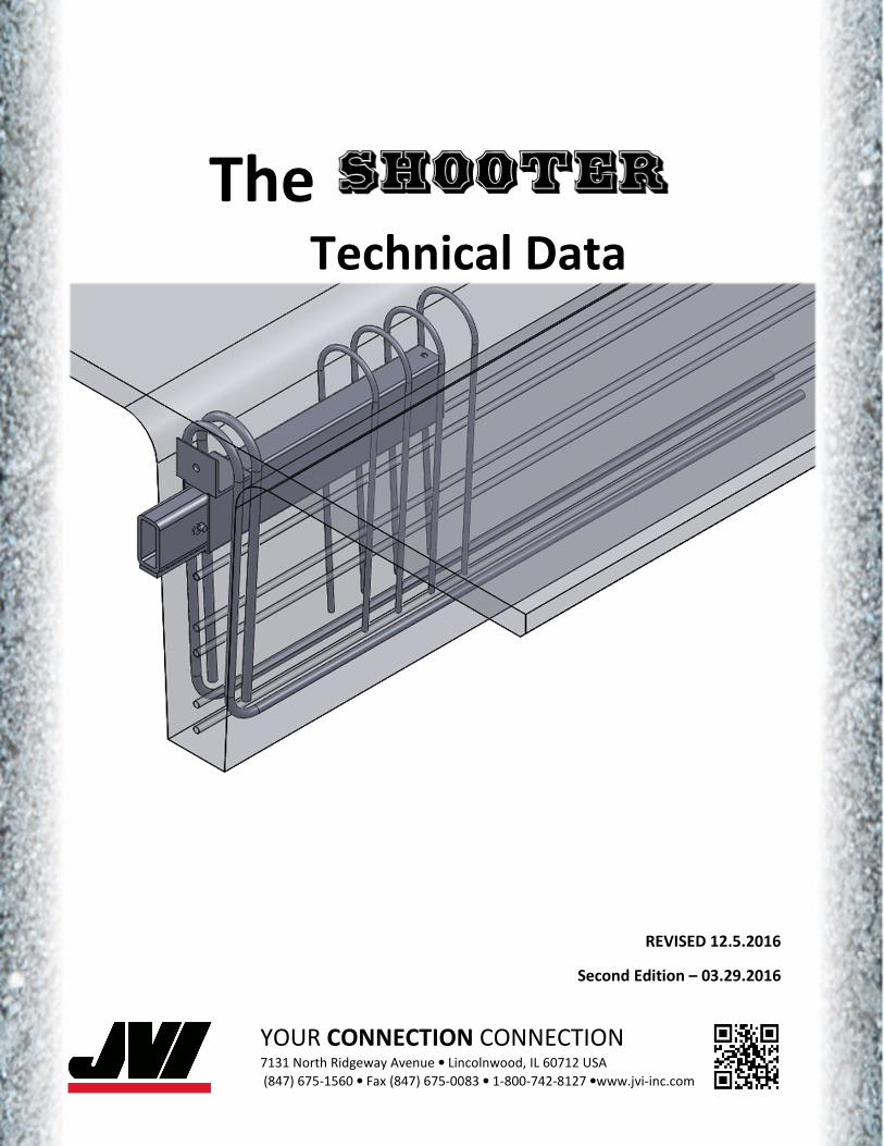
The Shooter is provided with a hot dipped galvanized finish according to the European specification NS-
EN ISO 1461. ISO 1461 is essentially equivalent to ASTM A1232.
Mechanical Mechanical Mechanical Mechanical Design StrengthDesign StrengthDesign StrengthDesign Strength Full scale test results3 have indicated that the Shooter has a mechanical design Strength in excess of
40,000 lbs. The testing also indicated that a strut-and-tie model can be used to design any member
using the shooter as a connection. To achieve the mechanical design capacity of the Shooter sufficient
concrete must surround the shooter to develop the required compression strut capacity and reinforcing
must be supplied to develop the required tension strut capacity.
EEEExample Detailingxample Detailingxample Detailingxample Detailing
Figure 1.4 Example Detailing

The
Part 1 - Executive Summary
4
In ProductionIn ProductionIn ProductionIn Production
In the FieldIn the FieldIn the FieldIn the Field

The
Part 1 - Executive Summary
5
ReferencesReferencesReferencesReferences [1] Gilbert, Nick (2012). Structural Steel - S235, S275, S355 Chemical Composition, Mechanical
Properties and Common Applications. http://www.azom.com/article.aspx?ArticleID=6022
[2] Langill, Tom, (2002). ISO 1461 and ASTM A123. http://www.galvanizeit.org/education-and-
resources/resources/technical-faq-dr-galv/iso-1461-and-astm-a-123
[3] Poore, Lois E (2009). The Development of a Steel Embedded Connection for Double-Tee Beams.
Department of Civil and Environmental Engineering, Virginia Polytechnic Institute and State
University, Blacksburg, VA.

The
Part 2 – Design and Detailing
6
IntroductionIntroductionIntroductionIntroduction The design and detailing of the Shooter will be presented in 7 sections as noted below.
1. Mechanical Design Strength of the Shooter
2. Concrete Design Strength Using a Strut-And-Tie Model
3. Estimated Design Strengths based on Strut-And-Tie Model
4. Design and Detailing of the bearing pocket
5. Detailing Considerations
6. Summary of full scale test results
7. Further Research
Where applicable, design equations will be referenced directly to the appropriate design guide.
DisclaimerDisclaimerDisclaimerDisclaimer The information provided in this reference for the use of the Shooter connection system is not intended
to replace the Engineer’s judgment and skill in creating a building with appropriate structural integrity
and permanent connections required to withstand code prescribed gravity, lateral and torsional forces.
The examples presented are concepts intended as guide for the Engineer of Record’s consideration and
are not to be considered “for construction” documents. Neither JVI nor any of its consultants or
suppliers have any Engineer of Record responsibility, or responsibility for contractor use or application
of the Shooter connection system.
Mechanical Design Strength of the Mechanical Design Strength of the Mechanical Design Strength of the Mechanical Design Strength of the Shooter
The Shooter outer tube will be assumed to act as a shim, transferring forces from the inner tube to the
concrete. Compression blocks will be assumed starting at the face of concrete and centered on the back
of the inner tube as detailed in figure 2.1. The compression block width at the front of the tube will be
assumed equal to the width of the angle welded to the outer tube, provided the front compression
block length is no longer than the angle leg length. The compression block at the back of the inner tube
will be assumed equal to the width of the outer tube.
Force equilibrium can be represented by equations 2.1 and 2.2 and Figure 2.1.
Sum of Forces: �� � �����_��� ��� � �����_����� ����� � 0 Eq. 2.1
Sum of Moments:
�� ���� � ��2 � � �����_��� ��� ������� � � ��!� � ��2 � � 0 Eq. 2.2
Where:
��� � 0.85%�′�' ( ) 1.1�′�
Eq. 2.3
PCI 7th Ed. (6-83)
( �width of the component in which the shooter is cast � �����; ��� �,�-./0.��12./.��.345�,,2./ 0.�6
The
Part 2 – Design and Detailing
7
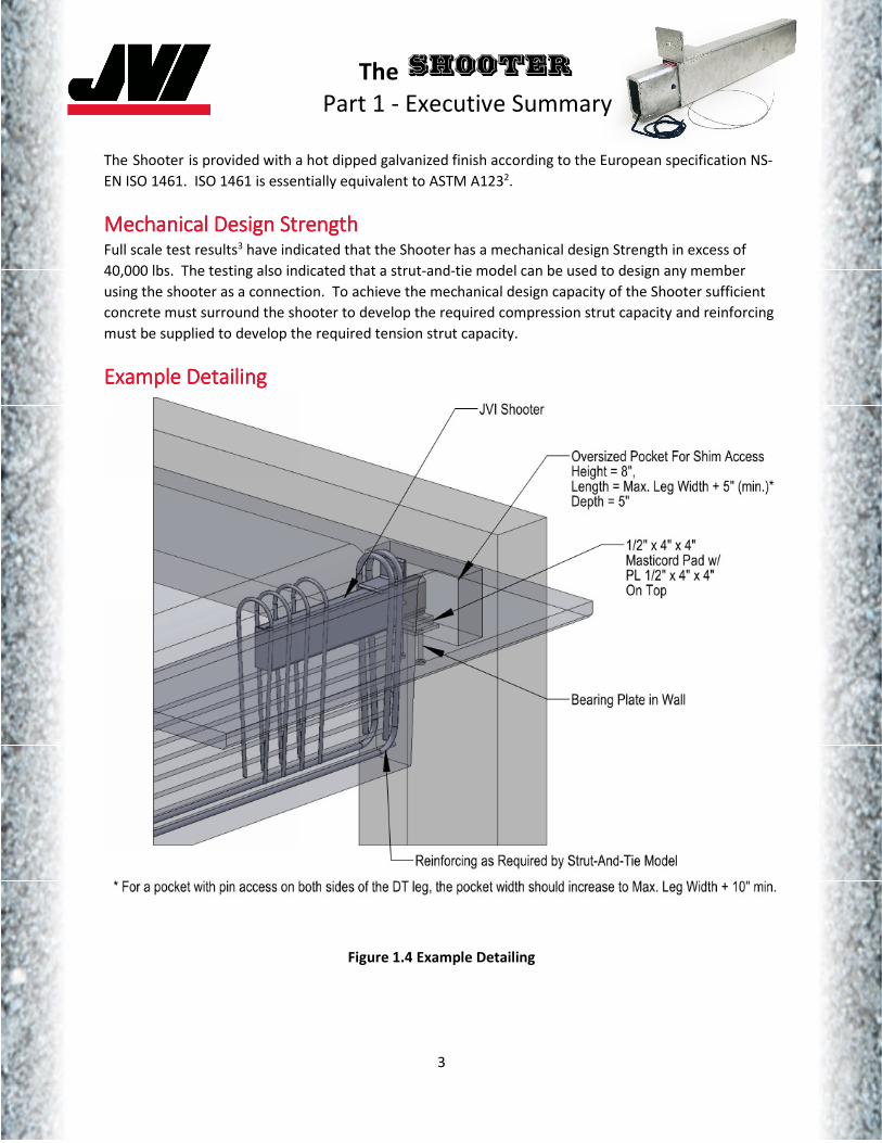
Figure 2.1 Shooter Equilibrium
Note: The stress distributions assumed at the face of the concrete and the back of the inner tube are based on PCI 7th Edition
Handbook , Eq. 6-831. Other stress distributions2 and simplifying assumptions3 have been applied to embedded steel sections
and may be substituted in lieu of the model presented at the discretion of the engineer.
Assuming:
�� � 40624 ��� � 82.5533 � 3.252/ �′� � 50004,2 ����� � 9033 � 3.5432/ ��� � 6033 � 2.3642/ ( � 190.533 � 7.52/
Solving equations 2.1 and 2.2:
�� � 3.9792/ �� � 1.4332/
Apply the results of equilibrium to evaluate the inner tube for shear and moment capacity.
The
Part 2 – Design and Detailing
8
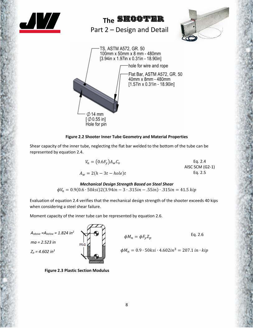
Figure 2.2 Shooter Inner Tube Geometry and Material Properties
Shear capacity of the inner tube, neglecting the flat bar welded to the bottom of the tube can be
represented by equation 2.4.
�� � <0.6=>?@(AB
@( � 2CD � 31 � D.0�E1 Eq. 2.4
AISC SCM (G2-1)
Eq. 2.5
Mechanical Design Strength Based on Steel Shear %�� � 0.9C0.6 ∙ 506,2E2C3.942/ � 3 ∙ .3152/ � .552/E ∙ .3152/ � 41.5624
Evaluation of equation 2.4 verifies that the mechanical design strength of the shooter exceeds 40 kips
when considering a steel shear failure.
Moment capacity of the inner tube can be represented by equation 2.6.
%G� � %=>HI Eq. 2.6
%G� � 0.9 ∙ 506,2 ∙ 4.6022/J � 207.12/ ∙ 624
Figure 2.3 Plastic Section Modulus
Aabove =Abelow = 1.824 in2
ma = 2.523 in
Zp = 4.602 in3
The
Part 2 – Design and Detailing
9
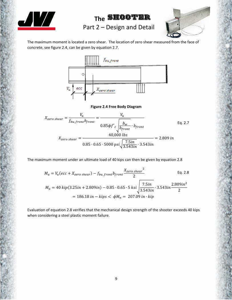
The maximum moment is located a zero shear. The location of zero shear measured from the face of
concrete, see figure 2.4, can be given by equation 2.7.
Figure 2.4 Free Body Diagram
KL���MN�� � �����_����� ����� � ��0.85%�′�' ( ����� ∙ �����
Eq. 2.7
KL���MN�� � 40,0000 ,0.85 ∙ 0.65 ∙ 50004,2P 7.52/3.5432/ ∙ 3.5432/
� 2.8092/
The maximum moment under an ultimate load of 40 kips can then be given by equation 2.8
G� � ��C��� � KL���MN��E � ���_����� ����� KL���MN���2 Eq. 2.8
G� � 40624C3.252/ � 2.8092/E � 0.85 ∙ 0.65 ∙ 56,2' 7.52/3.5432/ ∙ 3.5432/ 2.8092/�
2� 186.182/ � 624, Q %G� � 207.092/ ∙ 624
Evaluation of equation 2.8 verifies that the mechanical design strength of the shooter exceeds 40 kips
when considering a steel plastic moment failure.

The
Part 2 – Design and Detailing
10
Concrete Design Strength Using a StrutConcrete Design Strength Using a StrutConcrete Design Strength Using a StrutConcrete Design Strength Using a Strut----AndAndAndAnd----Tie ModelTie ModelTie ModelTie Model Full scale tests have shown that a strut-and-tie model may be used to design any member using the
Shooter as a connection3. The model will be developed assuming struts at the location of the reactions
of the inner tube (see figure 2.1) as well as the location of supplied reinforcing. Strut locations must also
be within the ACI 318-11 limits defined by A2.5. Figure 2.5 represents the assumed model.
Figure 2.5 Strut-And-Tie Model
It should be noted that the “X” dimension in Figure 2.5 is located at the centroid of the reinforcing
supplied for TF1. Since this reinforcing is not mechanically attached to the Shooter and the force must
be transferred to the reinforcing steel through an assumed front compression block in the concrete, it is
suggested that the reinforcing steel be distributed evenly over the length of the compression block with
the centroid ideally located at the center of the front compression block.
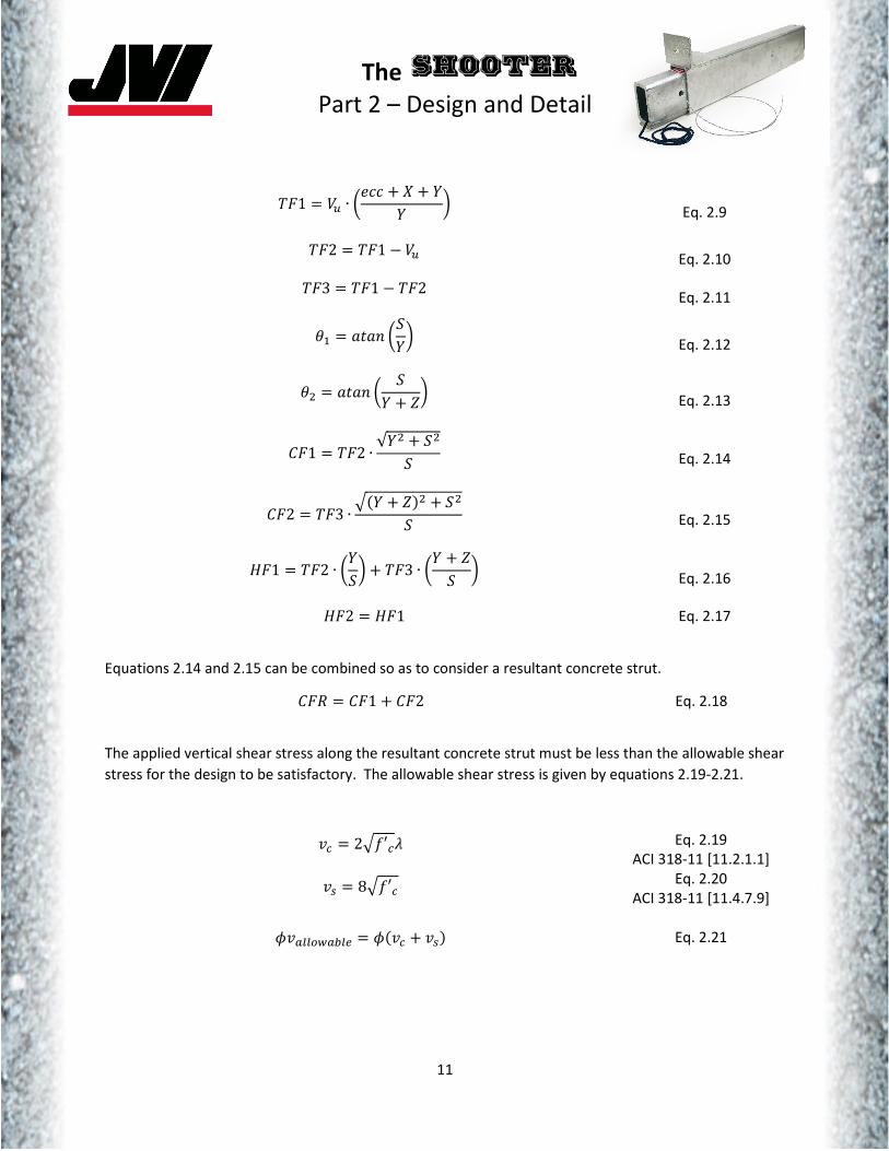
Using the geometry represented in Figure 2.5 the forces in the struts can be give by equations 2.9-2.17.
The
Part 2 – Design and Detailing
11
�=1 � �� ∙ R��� � K � SS T
Eq. 2.9
�=2 � �=1 � ��
Eq. 2.10
�=3 � �=1 � �=2
Eq. 2.11
U� � �1�/ RVST
Eq. 2.12
U� � �1�/ R VS � HT
Eq. 2.13
A=1 � �=2 ∙ √S� � V�V
Eq. 2.14
A=2 � �=3 ∙ XCS � HE� � V�V
Eq. 2.15
Y=1 � �=2 ∙ RSVT � �=3 ∙ RS � HV T
Eq. 2.16
Y=2 � Y=1 Eq. 2.17
Equations 2.14 and 2.15 can be combined so as to consider a resultant concrete strut.
A=Z � A=1 � A=2 Eq. 2.18
The applied vertical shear stress along the resultant concrete strut must be less than the allowable shear
stress for the design to be satisfactory. The allowable shear stress is given by equations 2.19-2.21.
[� � 2X�′�\
[M � 8X�′�
Eq. 2.19
ACI 318-11 [11.2.1.1]
Eq. 2.20
ACI 318-11 [11.4.7.9]
%[]]�(�]� � %C[� � [ME
Eq. 2.21

The
Part 2 – Design and Detailing
12
The applied vertical shear stress can be represented by equations 2.22-2.24.
� ��I � ���2
Eq. 2.22
@B � C � ^����_���ECY � -′E Eq. 2.23
[� � �=1@B Eq. 2.24
The effective strength of nodal zones is governed by ACI 318-11 A.5 and can be given by equation 2.25.
The effective strength of the nodal zone must be greater than the applied stress at the node due to the
resultant compression strut for the design to be satisfactory.
%��� � %0.85 ∙ `��′�
`� � 0.6\
Eq. 2.25
ACI 318-11 [A5.2]
Eq. 2.26
ACI 318-11 [A5.2.3]
Node geometry is dependent on reinforcing geometry. The width of the nodal zone can be determined
assuming a distance between reinforcing bars plus 2 times the cover (see figure 2.7).
Figure 2.7 Example Nodal Zone
Figure 2.6 Stem Dimensions

The
Part 2 – Design and Detailing
13
Prestressing strand can be considered with regard to nodal zone reinforcing and overall strut geometry
at the discretion of the engineer.
Assuming the geometry given by figure 2.7, the applied stress at the nodal zone can be given by
equations 2.27-2.28.
@�L � XV15 1a2-1D��512��0� � V15 1a2-1DY.52b./1�0� ∙ 1��c�
�� � A=Z@�L
Eq. 2.27
Eq. 2.28
The effective strength of compression struts is governed by ACI 318-11 A.3 and can be given by
equations 2.29-2.30. The effective strength of the compression strut must be greater than the applied
stress at the node due to the resultant compression strut for the design to be satisfactory.
%��� � %0.85 ∙ M̀�′�
M̀ � 0.6\
Eq. 2.29
ACI 318-11 [A3.2]
Eq. 2.30
ACI 318-11 [A3.2.2]
The strut will be critical at the location of the shooter, where the strut width should be reduced by the
width of the outer tube. Still applying the geometry from figures 2.6 and 2.7, the stress in the strut can
be given by equations 2.31-2.32.
@�M � XV15 1a2-1D��512��0� � V15 1a2-1DY.52b./1�0� ∙ C � ���E
�� � A=Z@�M
Eq. 2.31
Eq. 2.32
It should be noted that assuming an inclined width, see figure 2.7, of the compression strut would result
in a strut width less than the nodal width. This reduces the capacity of the compression strut by less
than 4% and has been neglected.
The reported value of M̀ in equation 2.30 can be increased based on supplied reinforcement as defined
by ACI 318-11 A3.2.2(a).
The required reinforcement for strut forces TF1, TF2, TF3 and HF1 should be supplied based on equation
2.33 and ACI 318-11 A.4.
@�M � V15 1=.5��%�> Eq. 2.33
Where �> is the yield strength of the supplied reinforcing.

The
Part 2 – Design and Detailing
14
The HF1 reinforcing requirement can consider contributions due to prestressing strand through the use
of an extended nodal zone per ACI 318-11 RA.4.3. Due to the variance in supplied prestressing strand
geometry, the prestressing strand contribution has not been covered. A detailed example of how to
apply the extended nodal zone can be found in reference 3.
The compression strut resulting from HF2 can be resolved by using the effective compression strut
strength represented by equation 2.29. The stress in the compression strut can be given by Eq. 2.34 and
2.35.
@�M � 2 ∙ -′ Eq. 2.34
��� � Y=2@�M Eq. 2.35
If effective strength of the compression strut is greater than the applied stress, the strut is satisfactory.
The strut reinforcing should be located so as to maintain the initial geometry of the assumed strut-and-
tie model.
The contribution of a normal force has been neglected due to the inherent ability of the Shooter to
allow for axial volume movements.
Recommended Design Strengths based on StrutRecommended Design Strengths based on StrutRecommended Design Strengths based on StrutRecommended Design Strengths based on Strut----AnAnAnAn----Tie ModelTie ModelTie ModelTie Model Using the strut-and-tie model described above, assuming the simplified double tee geometry shown in
figure 2.8, and assigning d’ =4in, S= H-d’ -2.5in, and Strut Width Vertical = Strut Width Horizontal = 5.5in
the following recommendations for design strength are presented.
Figure 2.8 Simplified Double Tee Geometry

The
Part 2 – Design and Detailing
15
Recommended Design Strength Based on f'c = 5000 psi
H
(in)
B
(in)
φφφφVn
(kip) Controlling Factor
24
6 24.25 Compression Stress at Resultant Concrete Strut @ Shooter (CFR) Eq. 2-29
8 30.25 Compression Stress at Resultant Concrete Strut @ Node (CFR) Eq. 2-29*
10 30.5 Compression Stress at Resultant Concrete Strut @ Node (CFR) Eq. 2-29
28
6 27.0 Compression Stress at Resultant Concrete Strut @ Shooter (CFR) Eq. 2-29
8 33.0 Compression Stress at Resultant Concrete Strut @ Node (CFR) Eq. 2-29 *
10 33.25 Compression Stress at Resultant Concrete Strut @ Node (CFR) Eq. 2-29*
32
6 29.0 Compression Stress at Resultant Concrete Strut @ Shooter (CFR) Eq. 2-29
8 35.0 Compression Stress at Resultant Concrete Strut @ Node (CFR) Eq. 2-29*
10 35.5 Compression Stress at Resultant Concrete Strut @ Node (CFR) Eq. 2-29*
Recommended Design Strength Based on f'c = 6000 psi
24
6 27.5 Vertical Shear Along Resultant Concrete Strut @ Shooter (CFR) Eq. 2.21
8 36.25 Vertical Shear Along Resultant Concrete Strut @ Node (CFR) Eq. 2.21*
10 40.0 Mechanical Design Strength of the Shooter
28
6 32.5 Compression Stress at Resultant Concrete Strut @ Shooter (CFR) Eq. 2-29
8 39.75 Compression Stress at Resultant Concrete Strut @ Node (CFR) Eq. 2-29 *
10 40.0 Mechanical Design Strength of the Shooter
32
6 35.0 Compression Stress at Resultant Concrete Strut @ Shooter (CFR) Eq. 2-29
8 40.0 Mechanical Design Strength of the Shooter
10 40.0 Mechanical Design Strength of the Shooter
∗ Failure modes “@ Node” are governed by 4” minimum bottom of leg dimension. If the bottom of
the leg is wider than the 4” additional capacity is available beyond that reported.
Table 2.1 Recommended Design Strength
Values in table 2.1 should be considered estimates and not for construction values. For actual design
strength of member, the correct geometry and concrete strengths should be applied by a qualified
engineer. The table does not take into consideration of the required reinforcing at the tension struts
and whether or not adequate room would be available within the concrete section.

The
Part 2 – Design and Detailing
16
Design and Detailing of the bearing pocketDesign and Detailing of the bearing pocketDesign and Detailing of the bearing pocketDesign and Detailing of the bearing pocket The bearing width of the Shooter inner tube is minimal (figure 2.9). In
general the bearing width will need to be increased to allow for the
design of the concrete bearing surface.
If steel shims are used a bearing plate should be embedded in the
receiving pocket with adequate thickness to distribute the load from the
inner tube to a sufficient concrete area that satisfies plain concrete
bearing.
Additionally, the use of a bearing pad may be desired to account for non-
uniform bearing due to double tee rotation and inner tube rotation inside
the outer tube (Figure 2.10). A sufficient area of bearing pad needs to be
engaged to allow the bearing pad to design as well as satisfy plain
concrete bearing of the receiving pocket. This can be accomplished by installing a plate with sufficient
thickness to engage the required area of bearing pad. The bearing pad can be designed assuming the
engaged area and utilizing the equations in Masticord Design Guide Third Edition6. The use of an
embedded bearing plate in the receiving pocket in addition to the bearing pad may be detailed to
provide redundancy in the design at the discretion of the engineer.
The bearing shim or pad should be located so as to consider spall concerns of the receiving pocket and
to minimize eccentricity on the Shooter. Actual eccentricity based on joint geometry and bearing shim
or pad location should be considered in the final design of the Shooter.
Detailing ConsiderationsDetailing ConsiderationsDetailing ConsiderationsDetailing Considerations
Figure 2.10 illustrates detailing concerns for the Shooter.
1. The front bars should hook over the top of the shooter (figure 2.11) and be developed past the
bottom of the outer tube. If they do not extend the development length past the bottom of the
outer tube, they should be hooked or otherwise mechanically anchored.
2. The front bar(s) should also be hooked to develop the horizontal tension strut, HF1 (figure 2.5).
They should extend the development length past the horizontal strut width at the nodal zone.
3. Vertical strut reinforcing not at the front of the shooter should extend the development length
past the bottom of the tube. The bottom of the tube is assumed to provide developed
reinforcing crossing a potential crack plane at the interface between the tube and the concrete.
If sufficient depth is not available to develop the bars, the bars should be hooked or otherwise
mechanically anchored to develop the bar. The bars also need to be developed above the top of
the outer tube. This can be achieved by hooking the bars or otherwise mechanically anchoring
the bars. Unlike the front bars, the direction of the hook is not critical and can be detailed per
preferred production standards.
4. Shooter reinforcing is considered in addition to shear and flexural reinforcing.
5. Additional longitudinal reinforcing (not shown) can be provided as crack control, normal force
reinforcement and to assist in cage assembly above and below the tube.
Figure 2.9 Bearing Width

The
Part 2 – Design and Detailing
17
Figure 2.10 Detailing Considerations
Figure 2.11 Front Bar Hook Requirement

The
Part 2 – Design and Detailing
18
SummSummSummSummary of full scale test resultsary of full scale test resultsary of full scale test resultsary of full scale test results Full scale tests were performed at Virginia Polytechnic Institute and State University in 2009. The full
report can be found in reference 2. Please consult the reference for complete details.
A total of (4) tests were conducted. In each test, the Shooter mechanical capacity was not in question.
Strain gauges applied to the reinforcing bars for each test indicate that the reinforcing closest to the end
of the double tee experienced larger strains than bars located farther from the end of the double tee.
The strain in the bars closest to the end of the double tee increased linearly as the load was increased.
The strut-and-tie model was superimposed on the results of the test strains. The results indicated that
the strut-and-tie model was conservative.
Further ResearchFurther ResearchFurther ResearchFurther Research The shooter was initially tested assuming flat bearing conditions. Slopes due to traditional drainage and
camber are considered to be addressed by the initial testing. Additional testing was completed to
validate the shooter on a parking ramp as illustrated in figure 2.12. The slope was limited to 6.67%, the
maximum parking slope allowed by the International Building code. The maximum end reaction
obtained during tested was 30.8 kips. The test was stopped as the double tee was not to be tested to
failure. The results indicate that the inclusion of a ramp does not lead to any additional cracking of the
concrete nor impact on steel performance.
Additional testing should be complete to failure to assess a final design strength of the shooter on a
ramped double tee.
Figure 2.12 Parking Ramp Slope

The
Part 2 – Design and Detailing
19
ReferencesReferencesReferencesReferences [1] Precast Concrete Handbook Committee (2010). PCI Design Handbook 7th Edition, Precast Concrete
institute, Chicago, IL
[2] Marcakis, K., and D. Mitchell (1980). Precast Concrete Connections with Embedded Steel Members.
PCI Journal, V. 25, No. 4 (July-August).
[3] Poore, Lois E (2009). The Development of a Steel Embedded Connection for Double-Tee Beams.
Department of Civil and Environmental Engineering, Virginia Polytechnic Institute and State
University, Blacksburg, VA.
[4] American Institute of Steel Construction (2005). Manual of Steel Construction, 13th edition, AISC,
Chicago, IL
[5] ACI Committee 318-11 (2011). Building Code Requirements for Structural Concrete (ACI 318-11) and
Commentary (318R-11), American Concrete Institute, Chicago, IL.
[6] Masticord Design Guided Third Edition (1996). JVI, Inc, Lincolnwood, IL.

The
Part 3 – Production
20
The following discussion contains recommendations for production procedures to facilitate the
installation of the Shooter. Plant practices, processes and facilities may dictate alternate procedures. A
production plan specific to each facility, with consideration of the following recommendations, should
be evaluated prior to incorporating the Shooter into production.
InstalInstalInstalInstallationlationlationlation The Shooter assembly, see figure 3.1, is installed as a single component. The nylon string and steel wire
should be inserted into the inner tube and secured in place during casting. To ensure that concrete does
not get inside the inner tube, the end of the Shooter at the bulkhead should be taped or otherwise
sealed.
Item
No. Description
1 Inner Tube
2 Outer Tube
3 Pull Out Steel Wire
4 Pull In Nylon Wire
Figure 3.1 Shooter Assembly
It is recommended that the Shooter reinforcing cage be
assembled and considered as a single element for installation
in lieu of individually detailing and installing the rebar at the
bed to facilitate accurate installation locations. See Figure
3.2.
The Shooter must be adequately anchored to the bulkhead to
ensure the assembly does not rotate during casting. A rubber
mandrel that is fitted to the outer tube and bolted to the bulk
head, along with the back end tied to a “U” shaped rebar has
been employed to secure the Shooter with success.
Figure 3.2 Assembled Rebar Cage

The
Part 3 – Production
21
CastingCastingCastingCasting Due to congestion at the Shooter reinforcing, consolidation of concrete should be observed. The same
process used to ensure consolidation at dapped end reinforcing should be employed at the Shooter.
StorageStorageStorageStorage No special storage needs are required beyond the taping of the exposed end of the shooter. This
prevents water from getting into the tube and assists in securing the inner tube in place during
transportation and prior to erection. See Figures 3.3.
Figure 3.3 Taped End of the Shooter

The
Part 4 – Erection
22
The following discussion contains recommendations for erection procedures to facilitate erection of a
precast double tee using the Shooter as a gravity support. Erector or project specific requirements may
dictate alternate procedures. An erection plan specific to each erector and project, with consideration
of the following recommendations, should be evaluated prior to incorporating the Shooter.
PreparationPreparationPreparationPreparation The exposed ends of the Shooter should arrive sealed with tape or a similar tool. The sealant should be
removed and the push and pull strings placed on the top surface of the double tee. See figure 4.1.
Figure 4.1 the Shooter Push/Pull Strings Removed.
Bearing pads and associated shims should be put in place in the receiving pocket.
InstallationInstallationInstallationInstallation During placement of the double tee, the inner tube of the shooter is flush with the end of the double
tee. This allows the double tee to be moved into position without requiring an elevation change
between ends of the double tee, sometimes referred to as diving of the double tee. See figure 4.2.

The
Part 4 – Erection
23
Figure 4.2 Erection Orientation of Double Tee with the Shooter Bearing in Pocket
Once the double tee is lowered to the correct elevation, a steel wire
is used to pull out the inner tube. The top of the inner tube is
marked to indicate when the tube has been sufficiently removed. A
nylon string is available to pull the inner tube back into the outer
tube if the initial projection is excessive. See Figure 4.3.
Figure 4.3 Inner Tube Extraction
Once the tubes have been extracted the erection pin should be
installed. This pin prevents the inner tube from retracting back into
the outer tube (Figure 4.4). The receiving pocket is intentionally
oversized in the horizontal direction to allow the installation of the
pin. See Figure 4.5. Additionally, the receiving pocket is oversized
in the vertical direction to allow for any elevation adjustments to be
made with the inner tube remaining projected.
Figure 4.4 Erection Pin

The
Part 4 – Erection
24
Figure 4.5 Installation of Erection Pin
FireproofingFireproofingFireproofingFireproofing The bearing pocket should not be grouted to obtain a required fire rating. Instead an appropriate
flexible spray or fire proofing material should be utilized.
MaintenanceMaintenanceMaintenanceMaintenance Standard inspection processes for precast structures should be applied to the Shooter connection.

The
Appendix
25
AppendixAppendixAppendixAppendix The appendix consists of:
1. Plate Drawings
2. Example Detailing
3. Example Reinforcing
4. Example Calculations for the Strut-and-Tie Method
5. Example Calculations for bearing pad design
All are provided for concept only and should not be used for construction use.

TOTAL WEIGHT : 31.3 LBS
ALL STEEL IS GALVANIZED ACCORDING TO NS-EN ISO 1461
PART LIST
ITEM DESCRIPTION MATERIAL CUTTING L QTY wT. LBS
1 INNER TUBE 1 19.6
2 OUTER TUBE 1 11.7
3 WHITE ROPE NYLON 1500 1
4 BLUE ROPE NYLON 1500 1
Lincolnwood, Illnois 60712 USAJVI DT SHOOTER
__ __ __
Tel. 847/675-1560 - Fax 847/675-0083
DATE DRAWN CHECKED SCALE
02.15.2016 JVI __ __ __
7131 North Ridgeway Avenue
INNER AND OUTER TUBE ASSEMBLED WITH WIRE AND ROPE
110mm4.33in 21.46in
545mm
7.68
in19
5mm
3
2
14

2
1
3
__ __ ____ __ __JVI
JVI DT SHOOTER
Tel. 847/675-1560 - Fax 847/675-0083
DATE DRAWN CHECKED SCALE
02.15.2016
7131 North Ridgeway AvenueLincolnwood, Illnois 60712 USA
OUTER TUBE
NOTES:1. PLASTIC TOP SHOULD BE REINFORCED TO PREVENT FAILURE DURING PULL
TOTAL WEIGHT : 11.7 LBS
PART LIST
ITEM DESCRIPTION MATERIAL CUTTING L QTY WT. LBS
1 L 100X75X8 L=90 S355 90 1 2.1
2 TS 120X60X3 L=540 S355 540 1 9.6
3PLASTIC TOP (SEE NOTE 1)
1
2.36in60mm
3.54in90mm
37.500mm
1.48in
1.48in
37.500mm
0.12in3mm
60mm2.36in
0.59in15mm
0.59in15mm
0.55in
HOLE
14mm
4 50 x 1
4 50 x 1offset 10mm
120mm
4.72in
75mm
2.95in
3.94in100mm
540mm21.26in
0.20in5mm
21.46in545mm

TOTAL WEIGHT : 19.6 LBS
PART LIST
ITEM DESCRIPTION MATERIAL CUTTING L QTY WT. LBS
1 TS 100X50X8 L=480 S355 480 1 16.9
2 FLAT BAR 40X8 L=480 S355 480 1 2.7
3 STOP LABEL 1
JVI DT SHOOTER
__ __ ____ __ __
Tel. 847/675-1560 - Fax 847/675-0083
DATE DRAWN CHECKED SCALE
06.23.2014 JVI
7131 North Ridgeway AvenueLincolnwood, Illnois 60712 USA
INNER TUBE
4.25
in10
8mm
100m
m
1.97in50mm
8mm
0.31
in
40mm1.57in
3.94
in
0.31in8mm
1
2
3
HOLE FOR ROPE & WIRE
10mm10.500
mm0.41in
0.39in 0.98
in25
mm
4 127 X 3
4 127 X 3
480mm18.90in
50mm
1.97
in58
mm
2.28
in
3.74in95mm
5.00in
WELD127mm
14mm
THRU HOLE
0.55in
127mmWELD
5.00in 5.00in
WELD127mm

Oversized Pocket For Shim Access
Depth = 5"Length = Max. Leg Width + 5" (min.)* Height = 8",
Bearing Plate in Wall
On Top
JVI Shooter
1/2" x 4" x 4"Masticord Pad w/PL 1/2" x 4" x 4"
Reinforcing as Required by Strut-And-Tie Model
* For a pocket with pin access on both sides of the DT leg, the pocket width should increase to Max. Leg Width + 10" min.
JVI07.24.2014SCALE
__ __ __ N/A
JVI SHOOTER
Tel. 847/675-1560 - Fax 847/675-0083
DATE DRAWN CHECKED
7131 North Ridgeway AvenueLincolnwood, Illnois 60712 USA
DOUBLE TEE BEARING ON WALL

Title: Job No.: Date: 3.28.16
Subject: JVI 40 Kip Shooter Analysis
7131 North Ridgeway Ave.
Linco lnwood, Illino is 60712
1-800-742-8127
www.jvi-inc.com
Strut-Tie Model
Determine the forces at the front and the back of the inner tube using basic statics
Vertical Load Vu 40 kip⋅:=
Normal Load Nu 20% Vu⋅:=
Inner Tube Length Linner 480 mm⋅:=
Outer Tube Length Louter 540mm:=
Eccentricity ecc 3.25 in⋅:=
Tube Extention Tubeext 110mm:=
Concrete 28-day Strength f'c 5000 psi⋅:=
Concrete Bearing Width
Front bfront 90mm8 in⋅
90 mm⋅⋅:=
Back bback 60 mm⋅7.5 in⋅
60 mm⋅⋅:=
Strength Reduction Factor ϕ .65:=
Equations of Equilibrium
Sum of Forces Vu a2 .85⋅ ϕ⋅ f'c⋅ bback⋅+ a1 .85⋅ ϕ⋅ f'c⋅ bfront⋅− 0=
Sum of Moments Vu ecca1
2+
⋅ a2 .85⋅ ϕ⋅ f'c⋅ bback⋅ Linner Tubeext−a1
2−
⋅− 0=
Solve Block Solution CompressionBlocks Find a1 a2, ( ):= a1 CompressionBlocks1
:= a1 3.83 in⋅= a2 CompressionBlocks2
:= a2 1.404 in⋅=
The front compression block will transfer the force in the concrete to tension bars located near the face of the double tee. The centroid of
the tension bars, X, will be used in the strut-tie model to determine the node location for the strut-tie model. The centroid of the back
compression block will be used to locate the node for the CF1 Strut. The elevation of the node will be determined based on the centroid
of strut reinforcement. CF2 will be located within ACI 318-11 A2.5 provisions and centered on the provided reinforcing.
Xa1
2:= X 1.915 in⋅=
Y Linner Tubeext− X−:=
Y 12.652 in⋅=
d' 2.25 in⋅:=
H 28 in⋅:=
S H d'− 2.5 in⋅−:=
S 23.25 in⋅=
a2 1.404 in⋅=
Z Louter X− Y−:=
Z 6.693 in⋅=
ShooterAnalysis_Document.xmcd

Title: Job No. Date: 3.28.16
Subject: JVI 40 Kip Shooter Analysis
7131 North Ridgeway Ave.
Linco lnwood, Illino is 60712
1-800-742-8127
www.jvi-inc.com
Calculate Forces in Strut-Tie Model
TF1 TF1 Vuecc X+ Y+
Y
⋅:= TF1 56.329 kip⋅=
TF2 TF2 TF1 Vu−:= TF2 16.329 kip⋅=
TF3 TF3 TF1 TF2−:= TF3 40 kip⋅=
CF1 Angle θ1 atanS
Y
:= θ1 61.446 deg⋅=
θ1 atanS
Y Z+
:= θ1 50.238 deg⋅=CF2 Angle min angle = 25 deg ACI 3 18 -11 A2.5
CF1 CF1 TF2Y
2S
2+
S⋅:= CF1 18.59 kip⋅=
CF2 CF2TF3 Y Z+( )
2S
2+⋅
S:= CF2 52.035 kip⋅=
CF1 + CF2 CF1+CF2 CF1 CF2+:= CF1+CF2 70.626 kip⋅=
Location of TF2 and TF3 Resultant Force ZrTF2 0⋅ in⋅ TF3 Z⋅+
TF2 TF3+:= Zr 4.753 in⋅=
HF1 HF1 TF2Y
S
⋅ TF3Y Z+
S
⋅+:= HF1 42.167 kip⋅=
HF2 HF2 HF1:= HF2 42.167 kip⋅=
Beam Reinforcement as Required by forces in Strut-Tie Model
Material Properties Concrete f'c 5000 psi⋅= λ 1.0:= Rebar fy 60 ksi⋅:=
Strength Reduction Factors Flexure ϕf 0.9:= Shear ϕv 0.75:= Strut-Tie Models ϕst 0.75:=
Vertical Shear Along Diagonal Strut Allowable Shear Stress
Shear Capacity of Concrete[ACI 318-02 11.2.1.1]
Vc 2 f'c⋅ psi⋅ λ⋅:= Vc 141.421 psi⋅=
Steel Shear Strength Limit[ACI 318-11 11.4.7.9]
Vs 8 f'c⋅ psi⋅:= Vs 565.685 psi⋅=
Shear capacity of Concrete and Steel ϕVtotal ϕv Vc Vs+( )⋅:= ϕVtotal 530.33 psi⋅=
Vertical Shear at Resultant Concrete Strut, CFR
Stem Width @ Top of Shooter btop 8( ) in⋅:=
Stem Width @ Bottom of Shooter bbot 7.5 in⋅:=
Avereage Stem Width bbtop bbot+
2:= b 7.75 in⋅=
Width of Outer Tube bout 60 mm⋅:= bout 60 mm⋅=
Shear Area Av b bout−( ) H d'−( )⋅:=
Shear Stress vuTF1
Av:= vu 406.018 psi⋅=
Shear Capacity as Defined by ACI 318-11 is Adequate
ShooterAnalysis_Document.xmcd

Title: Job No. Date: 3.28.16
Subject: JVI 40 Kip Shooter Analysis
7131 North Ridgeway Ave.
Linco lnwood, Illino is 60712
1-800-742-8127
www.jvi-inc.com
Diagonal Compression Strut
Allowable Compression Strut Stess @ Node Zone ACI 318-11 A.5
Factor to account for the effect of cracking and reinforcement[ACI 318-11 A 5.2.3]
βs 0.6 λ⋅:=
Effective Compressive Strength of Concrete Strut[ACI 318-11 A 5.2 ]
ϕfce ϕst 0.85 βs⋅⋅ f'c⋅:= ϕfce 1912.5psi=
Compression Stress at Resultant Concrete Strut CFR @ Node
Strut geometry is dependent on reinfocing. The distance
beween reinforcing bars + 2 (cover) should be used to determine
the width of the strut.
Strut Width Vertical
[ACI 318-11 RA 4.2]
SWvertical 1.5 in⋅ 2⋅ 2.5 in⋅+:=
SWvertical 5.5 in⋅=
Strut Width Horizontal
[ACI 318-11 RA 4.2]
SWhorizontal 1.5 in⋅ 2⋅ 2.5 in⋅+:=
SWhorizontal 5.5 in⋅=
t 6 in⋅:=Zone Thickness
Zone Width w SWvertical2
SWhorizontal2
+:=
w 7.778 in⋅=
Area of Nodal Zone Anz w t⋅:= Anz 46.669 in2
⋅=
Stress in Compression Strut fuCF1+CF2
Anz:= fu 1513.328psi=
Compressive Strut Limit as Defined by ACI 318-11 is Adequate
Allowable Compression Strut Stess @ Strut ACI 318-11 A.3
Factor to account for the effect of cracking and reinforcement[ACI 318-11 A 3.2.2 (b)]
βs 0.75 λ⋅:=
Effective Compressive Strength of Concrete Strut[ ACI 318-11 A 3. ]
ϕfce ϕst 0.85 βs⋅⋅ f'c⋅:= ϕfce 2390.625psi=
Compression Stress at Resultant Concrete Strut CFR @ Shooter Elevation ACI 318-11 A.3
Strut Thickness t b bout−:= t 5.388 in⋅= Strut Thickness reduced by outer tube thickness
Resultant Compression Strut Angle θCFR atanS
Y Zr+
:= θCFR 53.182 deg⋅=
Nodal Zone Angle θzone atanSWvertical
SWhorizontal
:= θzone 45 deg⋅=
Inclined Width w SWvertical2
SWhorizontal2
+ cos 90 θCFR− θzone−( )⋅:= w 7.379 in⋅=
Area of Strut Acs w t⋅:= Acs 39.756 in2
⋅=
Stress in Compression Strut fuCF1+CF2
w t⋅:= fu 1776.481psi=
Compressive Strut Limit as Defined by ACI 318-11 is Adequate
ShooterAnalysis_Document.xmcd

Title: Job No. Date: 3.28.16
Subject: JVI 40 Kip Shooter Analysis
7131 North Ridgeway Ave.
Linco lnwood, Illino is 60712
1-800-742-8127
www.jvi-inc.com
Required Reinforcement for TF1(Hanger Reinforcement) TF1 56.329 kip⋅=
Required Steel As1TF1
ϕf fy⋅:= Supplied Steel
"Quantity" "Bar Size" "X-Location"
2 5 1
2 5 2.25
As1 1.043 in2
⋅=
Steel Supplied SuppliedAs1 1.24 in2
⋅=
Supplied As1 Steel is Adequate
Input CG for Hanger Reinforcement was 1.91 Acutal CG is 1.63
Required Reinforcement for TF2Assumes Stirrup Geometry when considering quantity
TF2 16.329 kip⋅=
Required Steel As2_1TF2
ϕf fy⋅:= Supplied Steel Stirrup Quantity Calculator
"Quantity" "Stirrup Size"
2 3
Preferred Stirrup Size Stirrup 5:=
As2_1 0.302 in2
⋅=
Quantity Required QTY ceilAs2_1
ArbStirrup2⋅
:=
QTY 1=
Steel Supplied SuppliedAs2_1 0.44 in2
⋅=
Supplied As2_1 Steel is Adequate
Required Reinforcement for TF3Assumes Stirrup Geometry when considering quantity
TF3 40 kip⋅=
Required Steel As2_2TF3
ϕf fy⋅:= Supplied Steel Stirrup Quantity Calculator
"Quantity" "Stirrup Size"
4 3
Preferred Stirrup Size Stirrup 4:=
As2_2 0.741 in2
⋅=
Quantity Required QTY ceilAs2_2
ArbStirrup2⋅
:=
QTY 2=
Steel Supplied SuppliedAs2_2 0.88 in2
⋅=
Supplied As2_2 Steel is Adequate
ShooterAnalysis_Document.xmcd

Title: Job No. Date: 3.28.16
Subject: JVI 40 Kip Shooter Analysis
7131 North Ridgeway Ave.
Linco lnwood, Illino is 60712
1-800-742-8127
www.jvi-inc.com
Required Reinforcement for HF1 HF1 42.167 kip⋅=
Hook As1 Reinforcement
to Satisfy As5 Input Not Required Supplied SteelBased on As1
Required Steel As5HF1
ϕf fy⋅:= Supplied Steel
AsSteel"Quantity" "Bar Size"
2 5
:=
As5 0.781 in2
⋅=
Steel Supplied SuppliedAs5 1.24 in2
⋅=
Supplied As5 Steel is Adequate
Steel Quantities and Bar Size information Based on As1 Input
Required Reinforcement for HF2 HF2 42.167 kip⋅=
Concrete Compression Strut Capacity
Factor to account for the effect of cracking and reinforcement[ACI 318-02 A 3.2.2 (b)]
βs 0.75 λ⋅:=
Effective Compressive Strength of Concrete Strut[ACI 318-02 A 3.2]
ϕfcu ϕv 0.85 βs⋅⋅ f'c⋅:= ϕfcu 2390.625psi=
Compressive Stress AreaAc d' 2⋅ b⋅:= Ac 34.875 in
2⋅=
Estimated Required Steel Supplied Steel
"Quantity" "BarSize"
-81·10 4As3HF2 Ac ϕfcu⋅−
ϕf fy⋅:=
As3 0.763− in2
⋅=
Supplied Steel Capacity is Reduced based on supplied development length as Compression development length,
where the assumed supplied development length is equal to the zone width. Concrete Compressive stress area is
reduced by the area of compression steel supplied.
Supplied Compression Capacity CompressionCapacity 83.373 kip⋅=
Supplied Compression Capacity is Adequate
Required Reinforcement for Fnu
Required Steel Supplied Steel
"Quantity" "BarSize"
2 3
As4Nu
ϕf fy⋅:=
As4 0.148 in2
⋅=
Steel SuppliedSupplied As4 Steel is Adequate
SuppliedAs4 0.22 in2
⋅=
ShooterAnalysis_Document.xmcd

Title: Job No. Date: 3.28.16
Subject: JVI 40 Kip Shooter Analysis
7131 North Ridgeway Ave.
Linco lnwood, Illino is 60712
1-800-742-8127
www.jvi-inc.com
Design is Sufficient for:
Vu = 40 kips
Nu = 8 kips
Image may not reflect bar quantities required in table below. Supply steel per table and not per image.
Quantity Bar Size
X-
Location Quantity
Stirrup
Size Quantity
Stirrup
Size
2 5 1 2 3 4 3
2 5 2.25
Quantity BarSize Quantity BarSize Quantity Bar Size
0.00 4 2 3 2 5
2 5
As1 Steel
As3 Steel As4 Steel As5 Steel
As2_1 Steel As2_2 Steel
ShooterAnalysis_Document.xmcd

Title: Job No.: Date: 7.25.14
Subject: Example Bearing Pad Design for Shooter Bearing
7131 North Ridgeway Ave.Lincolnwood, Illino is 60712
1-800-742-8127www.jvi-inc.com
Pad GeometryPad Width b1 4 in⋅:=
Pad Length w1 4 in⋅:=
Thickness t .5 in⋅:=
LoadingService Level Reaction Vservice 29.845 kip⋅:=
Calculations
Shape Factor
SFb1 w1⋅
2 b1 w1+( )⋅ t⋅:= SF 2=
Maximum Allowable Compressive Load
emax 40:= Recommended Design Value
Vnr 0.6 SF⋅ 2+( ) emax1.8⋅ b1⋅ w1⋅ psi⋅:= Vnr 39.172 kip⋅=
Angle of Rotation A 0.025 rad⋅:=
Rotation of Shooter in outer tube counter actsDT Camber. Shooter rotation is 0.017 rad. Assumea total rotation under a deflected DT of .025 rad.
Bearing Length w/ Rotation w2 min w140 t⋅
100 tan A( )⋅, ⎛⎜
⎝⎞⎟⎠
:= w2 4 in⋅=
Maximum Compressive Stress SnrVnr
b1 w2⋅:= Snr 2448.262 psi⋅= Must be less than 2500 psi
Reduction Factorkt 500=
R1
ktA
rad⎛⎜⎝
⎞⎟⎠
2⋅ 1+
:= R 0.762=
Allowable Compressive Load w/ Rotation Var R Vnr⋅:= Var 29.845 kip⋅=
BearingPadDesign.xmcd

Title: Job No. Date: 7.25.14
Subject: Example Bearing Pad Design for Shooter Bearing
7131 North Ridgeway Ave.Linco lnwood, Illino is 60712
1-800-742-8127www.jvi-inc.com
Shooter Inner Tube is not wide enough to engage entire bearing area of pad. Install Pad with a plate on top todistribute load to the entire pad. Determine Plate Thickness by modeling the plate using 2-D shell elements withthe bearing pad modeled assuming linear compression springs.
Determine spring constant assuming a shape factor for the entire pad geometry and applying the stress to anarea equal to the element area.
Shape Factor for 4 x 4 pad SF 2=
Stress equation for SF 2= σ e( ) 0.6 SF⋅ 2+( ) e1.8⋅ psi⋅:=
Strain Distributione 0 .01, emax..:=
Element Area Areaelement .5 .5⋅ in2⋅:=
Areaelement 0.25 in2⋅=
0 0.05 0.1 0.15 0.20
0.2
0.4
0.6
0.8
Actual DataLinear Approximation
Force vs. Displacement
Displacement, in
Forc
e, k
ip
The slope of the linear fit, assuming a y intercept of zero will be used as a spring constant
k Slopekipin
⋅:= k 2.5kipin
⋅=
Apply a surface load to shell elements at the location of the inner tube only.
Distributed Load Applied over 1.5" x 4" of Tube Bearing Area ω
Vservice1.5in 4⋅ in⋅
:= ω 716.28kip
ft2⋅=
Check FEA output to ensure that
Maximum displacement is not greater than emax100
t⋅ 0.2 in⋅=1.
2. Maximum Reaction at any Compression Spring is less than the maximum compressive stress without rotation x element area Reactionmax Areaelement Snr⋅( ):= Reactionmax 0.612 kip⋅=
3. Stresses in plate, not within the inner tube bearing area, are less than yield (increase element thickness at inner tube bearing area to simulate additional stiffness due to tube bearing.)
BearingPadDesign.xmcd

Title: Job No. Date: 7.25.14
Subject: Example Bearing Pad Design for Shooter Bearing
7131 North Ridgeway Ave.Linco lnwood, Illino is 60712
1-800-742-8127www.jvi-inc.com
Analysis run with a plate thickness of 1/2" and A36 Steel at areas without inner tube bearing and 1" thick andA36 steel at areas with direct inner tube bearing. Tube was assumed to be offset 1/2" from the center of theplate to create a worst case condition.
BearingPadDesign.xmcd