Embed Size (px)
Citation preview
1
1
Table of Contents 1.1 Cretile ProLogic ..................................................................................................................................... 3
1.2 Capabilities............................................................................................................................................ 4
1.2.1 INputs and OUTputs ....................................................................................................................... 4
1.2.2 Motor Control ................................................................................................................................ 4
1.2.3 Wireless Communication ............................................................................................................... 4
1.3 Internal details ...................................................................................................................................... 4
1.4 Software Installation guide ................................................................................................................... 5
1.4.1 Installing Arduino for Cretile .......................................................................................................... 5
1.4.2 Installing USB drivers for Cretile ProLogic (Windows 7, Windows 8) ............................................. 6
1.4.3 Using Android App Inventor extension .......................................................................................... 7
1.5 Using Arduino IDE and Ardublock ......................................................................................................... 8
1.5.1 Opening & configuring Arduino IDE and Ardublock ....................................................................... 8
1.5.2 Introduction to Ardublock ............................................................................................................ 12
1.6 ProLogic & Arduino Programming using Ardublock ............................................................................ 14
1.6.1 ProLogic program structure (Setup & Loop) ................................................................................ 14
1.6.2 Control structure .......................................................................................................................... 16
a. If then, if then else .................................................................................................................... 16
b. Loops ......................................................................................................................................... 18
a. While Loops............................................................................................................................... 18
b. Repeat Loops............................................................................................................................. 19
1.6.3 Variables ...................................................................................................................................... 20
1.6.4 Time functions ............................................................................................................................. 21
1.7 Details of ProLogic blocks in Ardublock .............................................................................................. 21
1.7.1 Working with ProLogic local INputs and OUTputs........................................................................ 21
a. Ready ProLogic without remote ................................................................................................ 22
b. WRITE ProLogic local output ..................................................................................................... 22
c. READ ProLogic local input ......................................................................................................... 22
Examples ........................................................................................................................................... 23
1.7.2 ProLogic remote INputs and OUTputs.......................................................................................... 27
2
2
a. Ready ProLogic remote IN ......................................................................................................... 27
b. Ready ProLogic remote OUT ..................................................................................................... 27
c. Ready ProLogic remote IN & OUT ............................................................................................. 28
d. WRITE ProLogic remote OUT..................................................................................................... 28
e. READ ProLogic remote IN .......................................................................................................... 29
Examples ........................................................................................................................................... 29
1.7.3 Using ProLogic motors ................................................................................................................. 32
a. SET Motor Speed ....................................................................................................................... 33
b. SET Motor Direction .................................................................................................................. 33
2. Developing ProLogic App on Android phone ........................................................................................ 34
2.1 Introduction ........................................................................................................................................ 34
2.2 Developing Android Application for ProLogic using App Inventor ...................................................... 34
2.2.1 First time login to App Inventor ................................................................................................... 34
2.2.1 Developing ProLogic Android application .................................................................................... 36
2.3 Writing your first Cretile Android App and ProLogic program ............................................................ 40
2.3.1 Cretile App Inventor blocks .......................................................................................................... 40
a. ProLogic.Start ................................................................................................................................ 40
b. ProLogic.ConnectionStatusChanged ............................................................................................. 41
c. ProLogic.InputValuesReceived .................................................................................................. 41
d. ProLogic.READ_IN ..................................................................................................................... 42
e. ProLogic.READ_remoteIN ......................................................................................................... 42
f. ProLogic.WRITE_OUT ................................................................................................................ 43
g. ProLogic.WRITE_remoteOUT .................................................................................................... 43
h. ProLogic.SET_motorSpeed ........................................................................................................ 44
2.3.2 Setting up your Android phone .................................................................................................... 45
2.3.3 Developing Android Application in App Inventor ......................................................................... 46
2.3.4 Installing application on android phone ....................................................................................... 53
2.3.5 Blocks for Mobile/PC communication in Ardublock ..................................................................... 53
2.3.6 Developing ProLogic Program to work with Android Application ................................................ 55
2.4 Connecting Android phone with ProLogic using USB-OTG .................................................................. 56
3
3
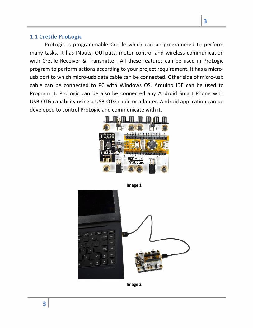
1.1 Cretile ProLogic
ProLogic is programmable Cretile which can be programmed to perform
many tasks. It has INputs, OUTputs, motor control and wireless communication
with Cretile Receiver & Transmitter. All these features can be used in ProLogic
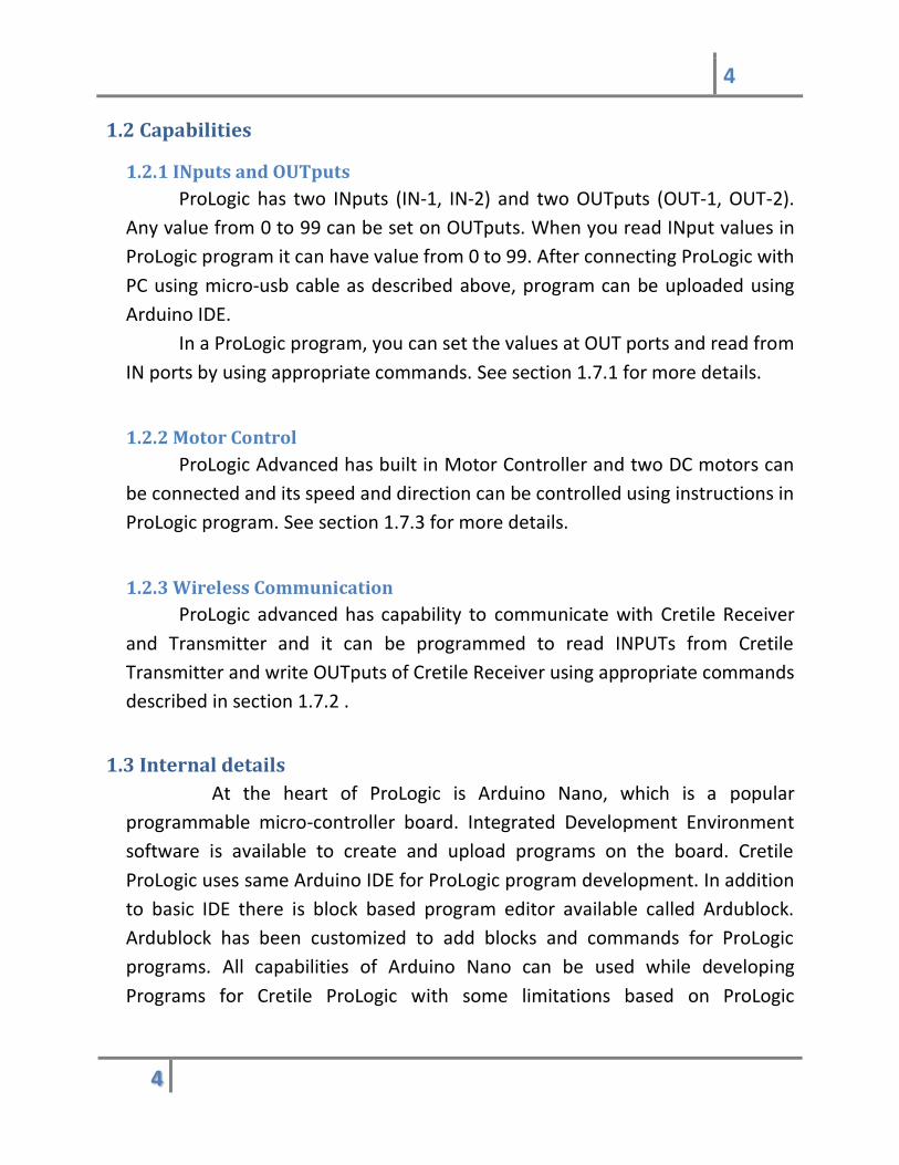
program to perform actions according to your project requirement. It has a micro-
usb port to which micro-usb data cable can be connected. Other side of micro-usb
cable can be connected to PC with Windows OS. Arduino IDE can be used to
Program it. ProLogic can be also be connected any Android Smart Phone with
USB-OTG capability using a USB-OTG cable or adapter. Android application can be
developed to control ProLogic and communicate with it.
Image 1
Image 2
4
4
1.2 Capabilities
1.2.1 INputs and OUTputs
ProLogic has two INputs (IN-1, IN-2) and two OUTputs (OUT-1, OUT-2).
Any value from 0 to 99 can be set on OUTputs. When you read INput values in
ProLogic program it can have value from 0 to 99. After connecting ProLogic with
PC using micro-usb cable as described above, program can be uploaded using
Arduino IDE.
In a ProLogic program, you can set the values at OUT ports and read from
IN ports by using appropriate commands. See section 1.7.1 for more details.
1.2.2 Motor Control
ProLogic Advanced has built in Motor Controller and two DC motors can
be connected and its speed and direction can be controlled using instructions in
ProLogic program. See section 1.7.3 for more details.
1.2.3 Wireless Communication
ProLogic advanced has capability to communicate with Cretile Receiver
and Transmitter and it can be programmed to read INPUTs from Cretile
Transmitter and write OUTputs of Cretile Receiver using appropriate commands
described in section 1.7.2 .
1.3 Internal details
At the heart of ProLogic is Arduino Nano, which is a popular
programmable micro-controller board. Integrated Development Environment
software is available to create and upload programs on the board. Cretile
ProLogic uses same Arduino IDE for ProLogic program development. In addition
to basic IDE there is block based program editor available called Ardublock.
Ardublock has been customized to add blocks and commands for ProLogic
programs. All capabilities of Arduino Nano can be used while developing
Programs for Cretile ProLogic with some limitations based on ProLogic

5
5
commands actually used in programs. For details about Arduino please visit
Arduino.cc
Image 3
1.4 Software Installation guide
1.4.1 Installing Arduino for Cretile
Please download Cretile Software ( Cretile.zip ) file from link received by
you from Cretile Support or Downloads section in
https://www.cretile.com/blog/download-software-and-documentation . Unzip
this in to a folder of your choice preferably to a path without any space in
name. After unzipping you will find following directory structure in folder.
In folder Arduino-1.8.3 you will find following files. Double click on
Arduino.exe to open Arduino for Cretile. For information on how to use
Arduino to develop ProLogic programs see section 1.5.

6
6
1.4.2 Installing USB drivers for Cretile ProLogic (Windows 7, Windows 8)
If you are using any Windows version prior to windows 10 (Windows 7,
Windows 8) then please install USB driver for Cretile ProLogic. The driver is
provided in Cretile.zip file. After unzipping you will find USBDriver folder as
shown in section 14.1. In this folder there is SETUP.exe file. Double click on this
file to install driver for ProLogic.
Double click this file to
open Arduino for Cretile
Double click this file to
install driver
7
7
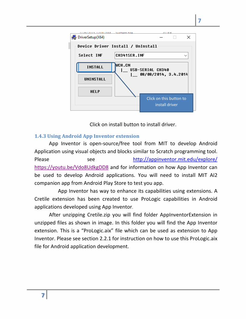
Click on install button to install driver.
1.4.3 Using Android App Inventor extension
App Inventor is open-source/free tool from MIT to develop Android
Application using visual objects and blocks similar to Scratch programming tool.
Please see http://appinventor.mit.edu/explore/
https://youtu.be/Vdo8UdkgDD8 and for information on how App Inventor can
be used to develop Android applications. You will need to install MIT AI2
companion app from Android Play Store to test you app.
App Inventor has way to enhance its capabilities using extensions. A
Cretile extension has been created to use ProLogic capabilities in Android
applications developed using App Inventor.
After unzipping Cretile.zip you will find folder AppInventorExtension in
unzipped files as shown in image. In this folder you will find the App Inventor
extension. This is a “ProLogic.aix” file which can be used as extension to App
Inventor. Please see section 2.2.1 for instruction on how to use this ProLogic.aix
file for Android application development.
Click on this button to
install driver
8
8
1.5 Using Arduino IDE and Ardublock
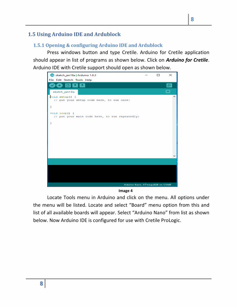
1.5.1 Opening & configuring Arduino IDE and Ardublock
Press windows button and type Cretile. Arduino for Cretile application
should appear in list of programs as shown below. Click on Arduino for Cretile.
Arduino IDE with Cretile support should open as shown below.
Image 4
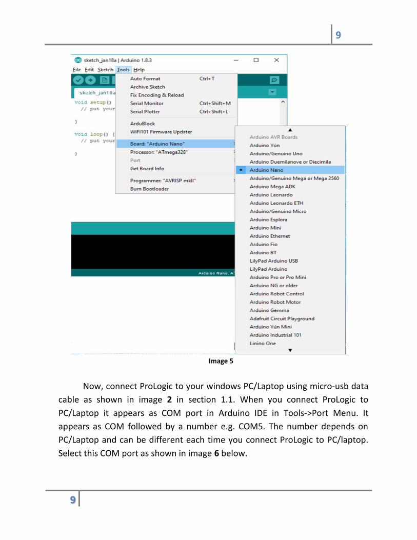
Locate Tools menu in Arduino and click on the menu. All options under
the menu will be listed. Locate and select “Board” menu option from this and
list of all available boards will appear. Select “Arduino Nano” from list as shown
below. Now Arduino IDE is configured for use with Cretile ProLogic.
9
9
Image 5
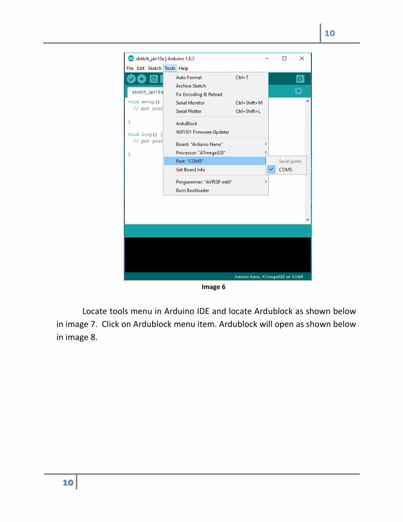
Now, connect ProLogic to your windows PC/Laptop using micro-usb data
cable as shown in image 2 in section 1.1. When you connect ProLogic to
PC/Laptop it appears as COM port in Arduino IDE in Tools->Port Menu. It
appears as COM followed by a number e.g. COM5. The number depends on
PC/Laptop and can be different each time you connect ProLogic to PC/laptop.
Select this COM port as shown in image 6 below.
10
10
Image 6
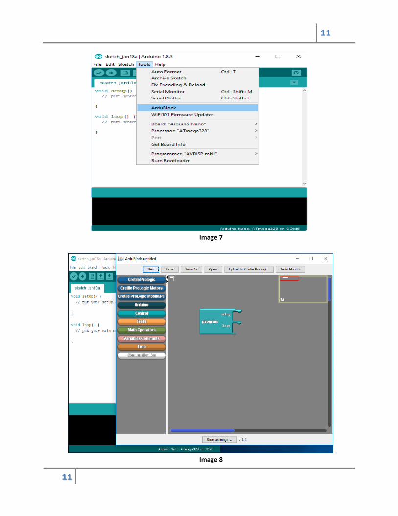
Locate tools menu in Arduino IDE and locate Ardublock as shown below
in image 7. Click on Ardublock menu item. Ardublock will open as shown below
in image 8.
11
11
Image 7
Image 8

12
12
1.5.2 Introduction to Ardublock
Ardublock has many Block Drawers. The block drawers are marked with
blue rectangle in image 9 below. Cretile ProLogic, Cretile Motors, Cretile
Mobile/PC communication are Cretile Block drawers. Each block drawer has set
of command block. Every command block performs certain function.
Information and help of each block can be seen by hovering mouse on block for
couple of seconds. Help on the block will appear as shown below in image 9.
Image 9
On the right side of block drawers section is Ardublock canvas where
blocks can be dragged and dropped to develop a program. Canvas has already
block for an empty program which does nothing. We will add block to make
ProLogic ready without remote connection. For this you need to click on Cretile
Block Drawers
Canvas
Blocks
13
13
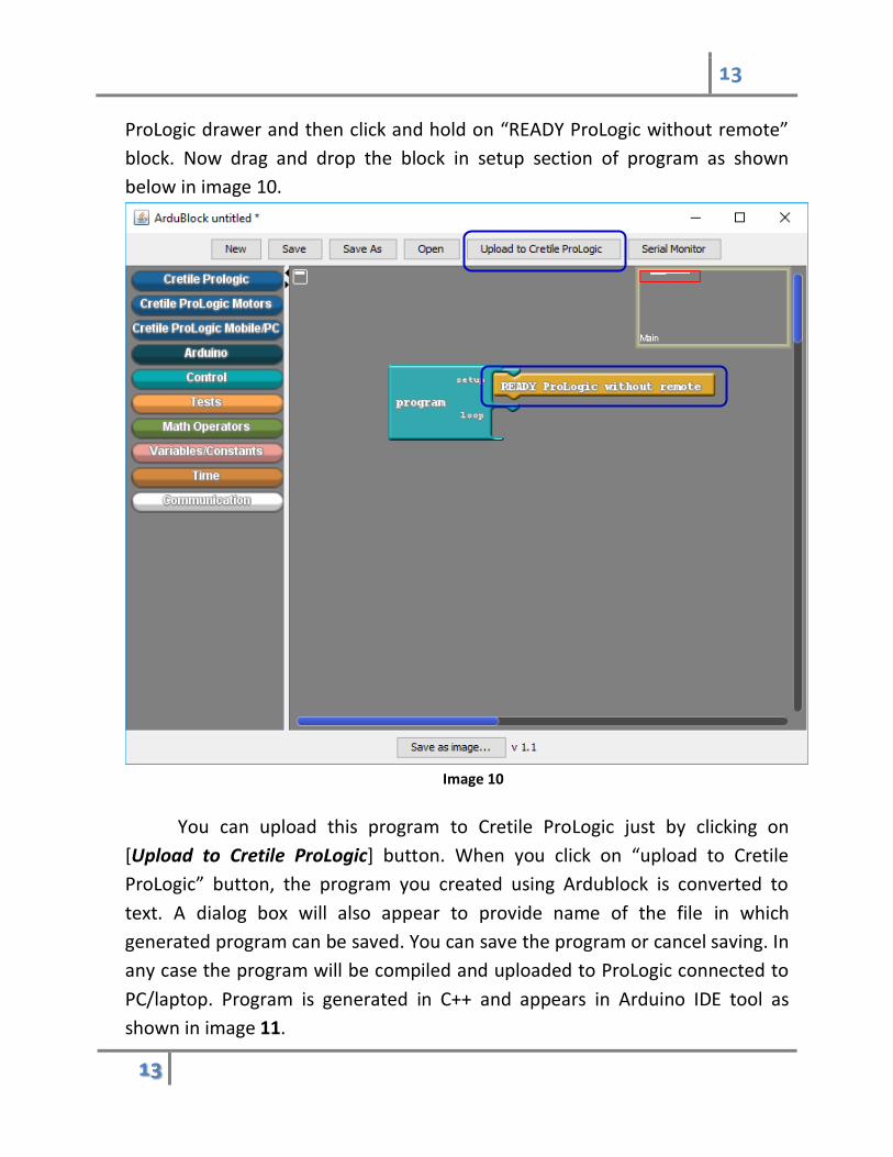
ProLogic drawer and then click and hold on “READY ProLogic without remote”
block. Now drag and drop the block in setup section of program as shown
below in image 10.
Image 10
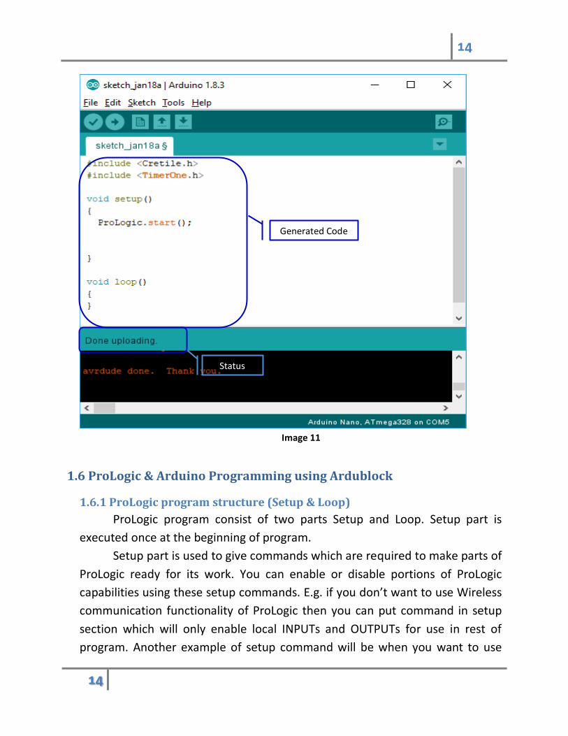
You can upload this program to Cretile ProLogic just by clicking on
[Upload to Cretile ProLogic] button. When you click on “upload to Cretile
ProLogic” button, the program you created using Ardublock is converted to
text. A dialog box will also appear to provide name of the file in which
generated program can be saved. You can save the program or cancel saving. In
any case the program will be compiled and uploaded to ProLogic connected to
PC/laptop. Program is generated in C++ and appears in Arduino IDE tool as
shown in image 11.
14
14
Image 11
1.6 ProLogic & Arduino Programming using Ardublock
1.6.1 ProLogic program structure (Setup & Loop)
ProLogic program consist of two parts Setup and Loop. Setup part is
executed once at the beginning of program.
Setup part is used to give commands which are required to make parts of
ProLogic ready for its work. You can enable or disable portions of ProLogic
capabilities using these setup commands. E.g. if you don’t want to use Wireless
communication functionality of ProLogic then you can put command in setup
section which will only enable local INPUTs and OUTPUTs for use in rest of
program. Another example of setup command will be when you want to use
Status
Generated Code
15
15
wireless communication capability, you need to tell serial number of receiver
and transmitter for establishing connection.
Once setup portion of program is executed, commands used in Loop part
of program are repeated forever in the sequence in which they are placed in
Loop part of the program. E.g. when you want to update OUTput of ProLogic
then command to write value of OUTput can be placed in loop and value can
change every time the command is executed based on whatever value is
supplied to the block. Another example is reading INput values from local and
remote INputs. You will get latest value of INputs every time read local or
remote IN block is executed.
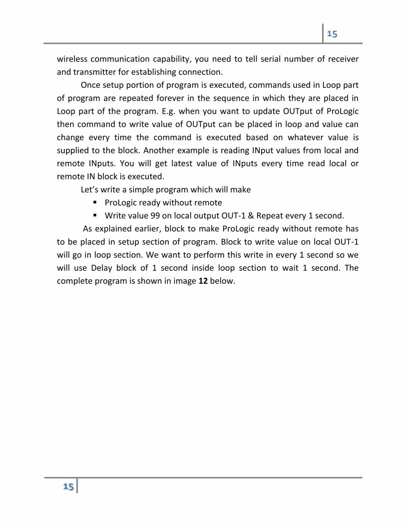
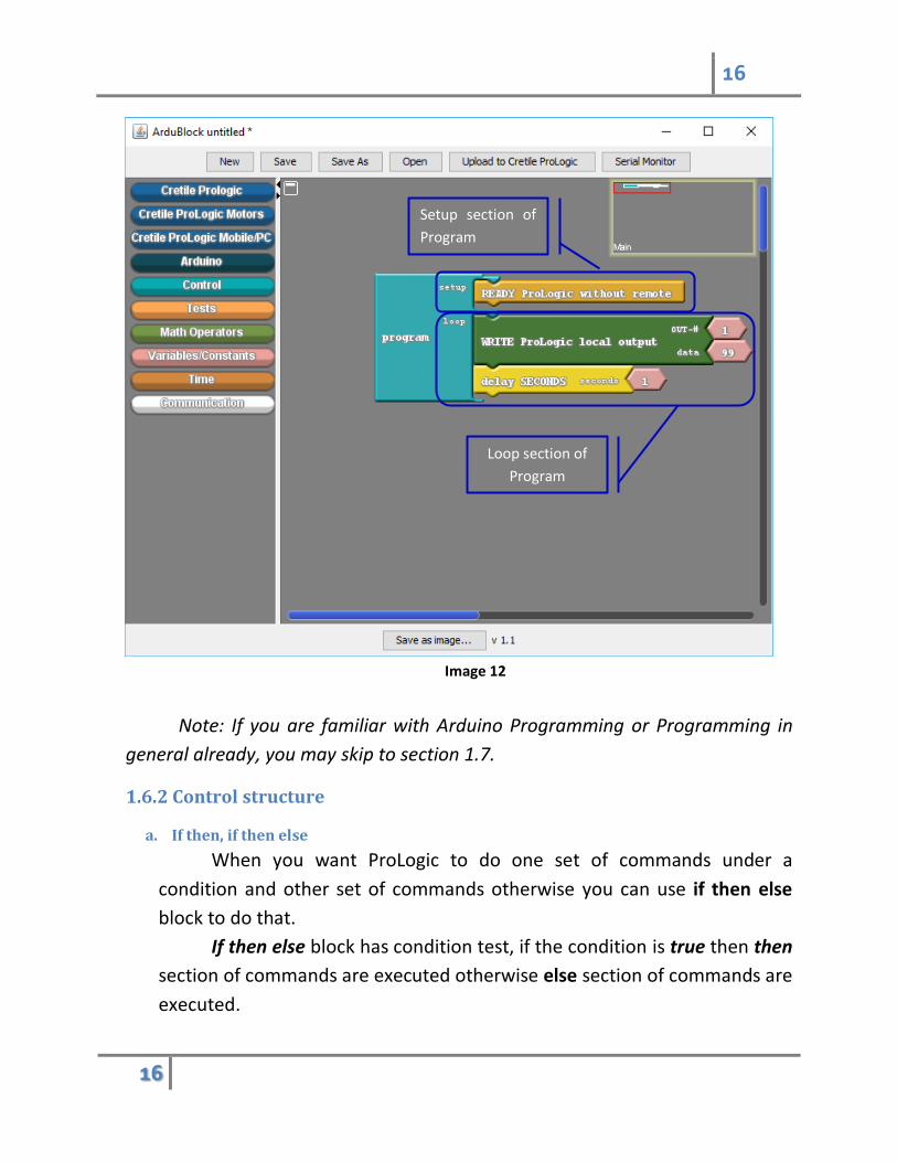
Let’s write a simple program which will make
ProLogic ready without remote
Write value 99 on local output OUT-1 & Repeat every 1 second.
As explained earlier, block to make ProLogic ready without remote has
to be placed in setup section of program. Block to write value on local OUT-1
will go in loop section. We want to perform this write in every 1 second so we
will use Delay block of 1 second inside loop section to wait 1 second. The
complete program is shown in image 12 below.
16
16
Image 12
Note: If you are familiar with Arduino Programming or Programming in
general already, you may skip to section 1.7.
1.6.2 Control structure
a. If then, if then else
When you want ProLogic to do one set of commands under a
condition and other set of commands otherwise you can use if then else
block to do that.
If then else block has condition test, if the condition is true then then
section of commands are executed otherwise else section of commands are
executed.
Setup section of
Program
Loop section of
Program
17
17
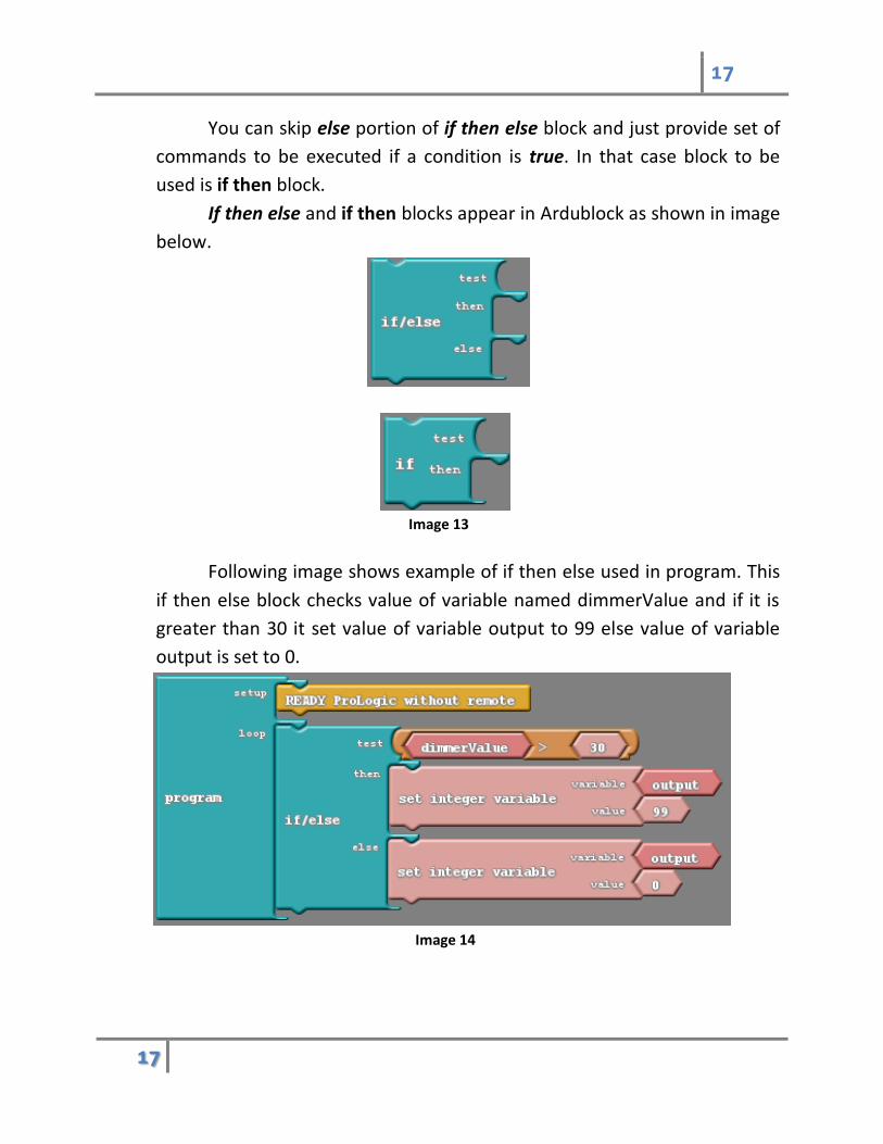
You can skip else portion of if then else block and just provide set of
commands to be executed if a condition is true. In that case block to be
used is if then block.
If then else and if then blocks appear in Ardublock as shown in image
below.
Image 13
Following image shows example of if then else used in program. This
if then else block checks value of variable named dimmerValue and if it is
greater than 30 it set value of variable output to 99 else value of variable
output is set to 0.
Image 14
18
18
b. Loops
When you want to repeat commands for certain number of time e.g.
five times or repeat commands until certain condition occurs, then these
loop type of control blocks can be used. Example of loop control blocks are
for, while and repeat.
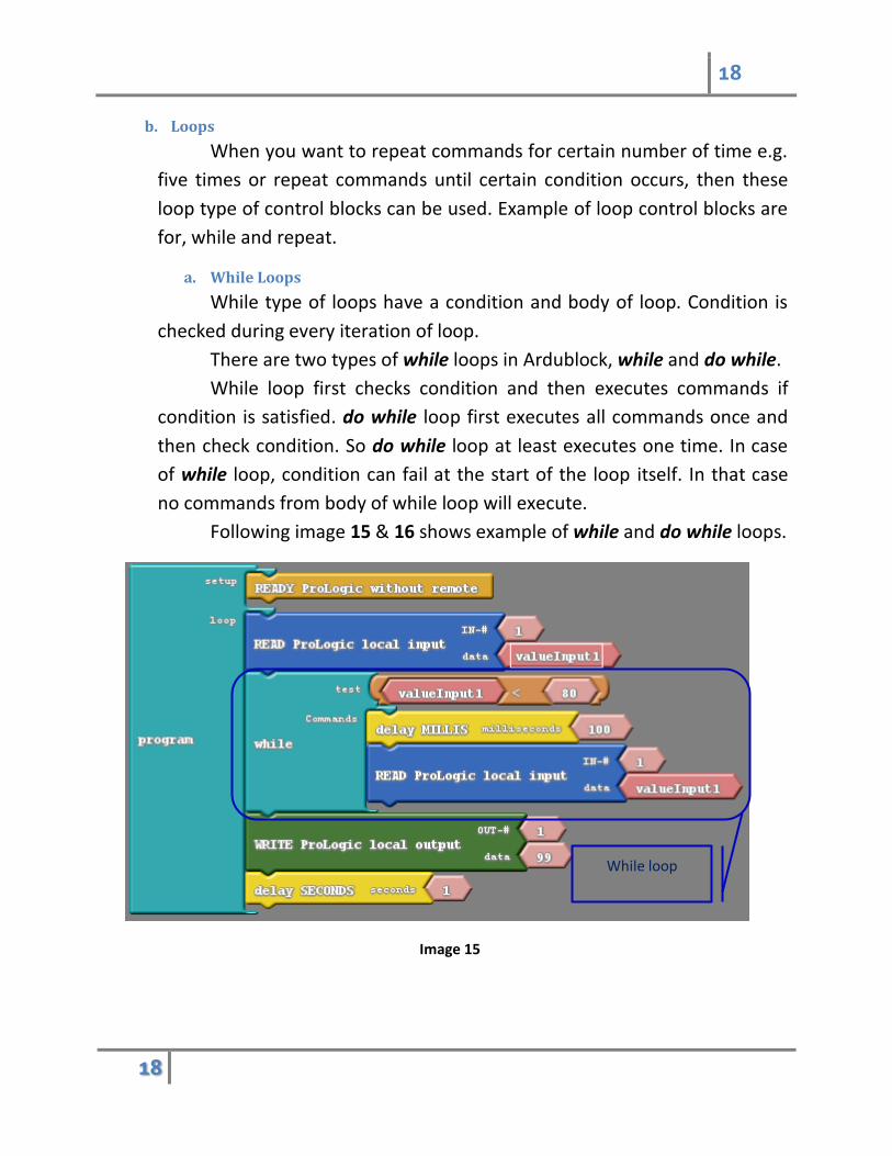
a. While Loops
While type of loops have a condition and body of loop. Condition is
checked during every iteration of loop.
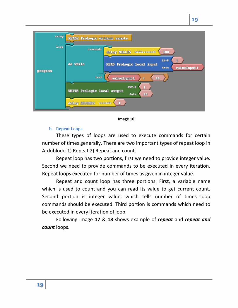
There are two types of while loops in Ardublock, while and do while.
While loop first checks condition and then executes commands if
condition is satisfied. do while loop first executes all commands once and
then check condition. So do while loop at least executes one time. In case
of while loop, condition can fail at the start of the loop itself. In that case
no commands from body of while loop will execute.
Following image 15 & 16 shows example of while and do while loops.
Image 15
While loop
19
19
Image 16
b. Repeat Loops
These types of loops are used to execute commands for certain
number of times generally. There are two important types of repeat loop in
Ardublock. 1) Repeat 2) Repeat and count.
Repeat loop has two portions, first we need to provide integer value.
Second we need to provide commands to be executed in every iteration.
Repeat loops executed for number of times as given in integer value.
Repeat and count loop has three portions. First, a variable name
which is used to count and you can read its value to get current count.
Second portion is integer value, which tells number of times loop
commands should be executed. Third portion is commands which need to
be executed in every iteration of loop.
Following image 17 & 18 shows example of repeat and repeat and
count loops.

20
20
Image 17
Image 18
1.6.3 Variables
Variables are place holders or memory of a specific type of value like
number or text. They are symbols which can remember value of specific type. A
number variable can remember any value between 1 to N.
Value of variable can be set by various commands e.g. command to read
ProLogic input can set value of variable with whatever is the value of ProLogic
21
21
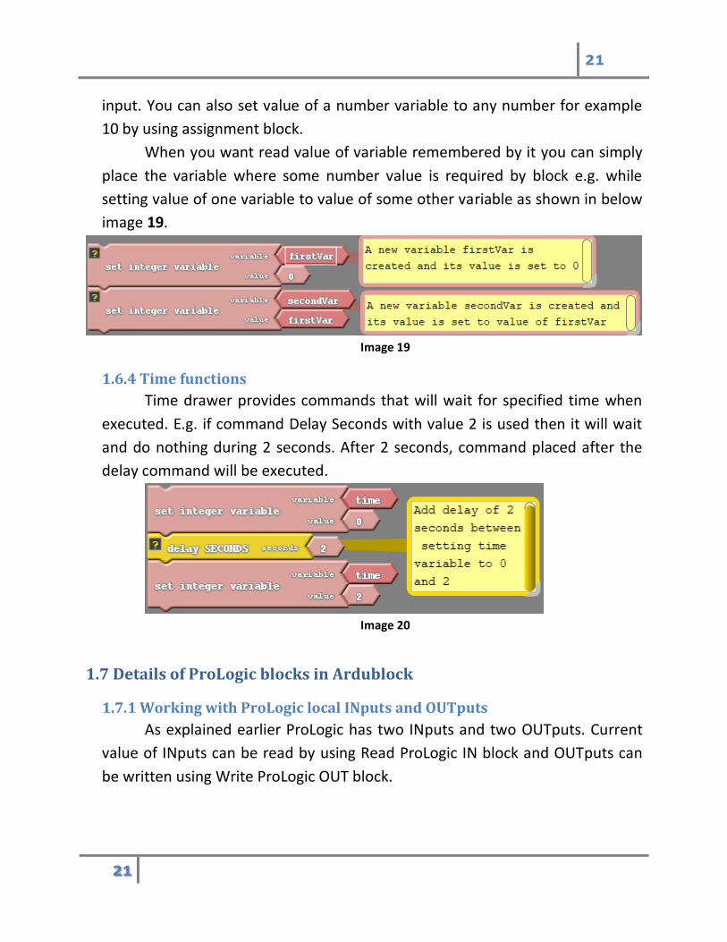
input. You can also set value of a number variable to any number for example
10 by using assignment block.
When you want read value of variable remembered by it you can simply
place the variable where some number value is required by block e.g. while
setting value of one variable to value of some other variable as shown in below
image 19.
Image 19
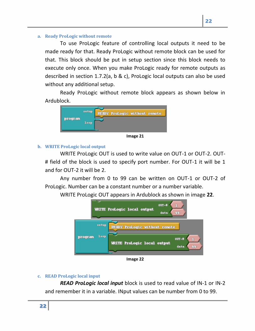
1.6.4 Time functions
Time drawer provides commands that will wait for specified time when
executed. E.g. if command Delay Seconds with value 2 is used then it will wait
and do nothing during 2 seconds. After 2 seconds, command placed after the
delay command will be executed.
Image 20
1.7 Details of ProLogic blocks in Ardublock
1.7.1 Working with ProLogic local INputs and OUTputs
As explained earlier ProLogic has two INputs and two OUTputs. Current
value of INputs can be read by using Read ProLogic IN block and OUTputs can
be written using Write ProLogic OUT block.
22
22
a. Ready ProLogic without remote
To use ProLogic feature of controlling local outputs it need to be
made ready for that. Ready ProLogic without remote block can be used for
that. This block should be put in setup section since this block needs to
execute only once. When you make ProLogic ready for remote outputs as
described in section 1.7.2(a, b & c), ProLogic local outputs can also be used
without any additional setup.
Ready ProLogic without remote block appears as shown below in
Ardublock.
Image 21
b. WRITE ProLogic local output
WRITE ProLogic OUT is used to write value on OUT-1 or OUT-2. OUT-
# field of the block is used to specify port number. For OUT-1 it will be 1
and for OUT-2 it will be 2.
Any number from 0 to 99 can be written on OUT-1 or OUT-2 of
ProLogic. Number can be a constant number or a number variable.
WRITE ProLogic OUT appears in Ardublock as shown in image 22.
Image 22
c. READ ProLogic local input
READ ProLogic local input block is used to read value of IN-1 or IN-2
and remember it in a variable. INput values can be number from 0 to 99.

23
23
READ ProLogic local input block appears in Ardublock as shown in
image 23.
Image 23
Examples
Let’s use these blocks to develop two simple programs
1. Blink
You will develop a program which will blink a light connected to
ProLogic OUT-1. For this program, you need Battery, ProLogic and Light
module. Connect these modules as show in image 24 below.
Image 24
To develop program Open Ardublock as explained in section 1.5.
In this program you don’t need wireless communication and motors
so you should make ProLogic ready without remote in setup section of
24
24
program. You don’t have to use READY ProLogic MOTORs block since you
are not going use motors in this program.
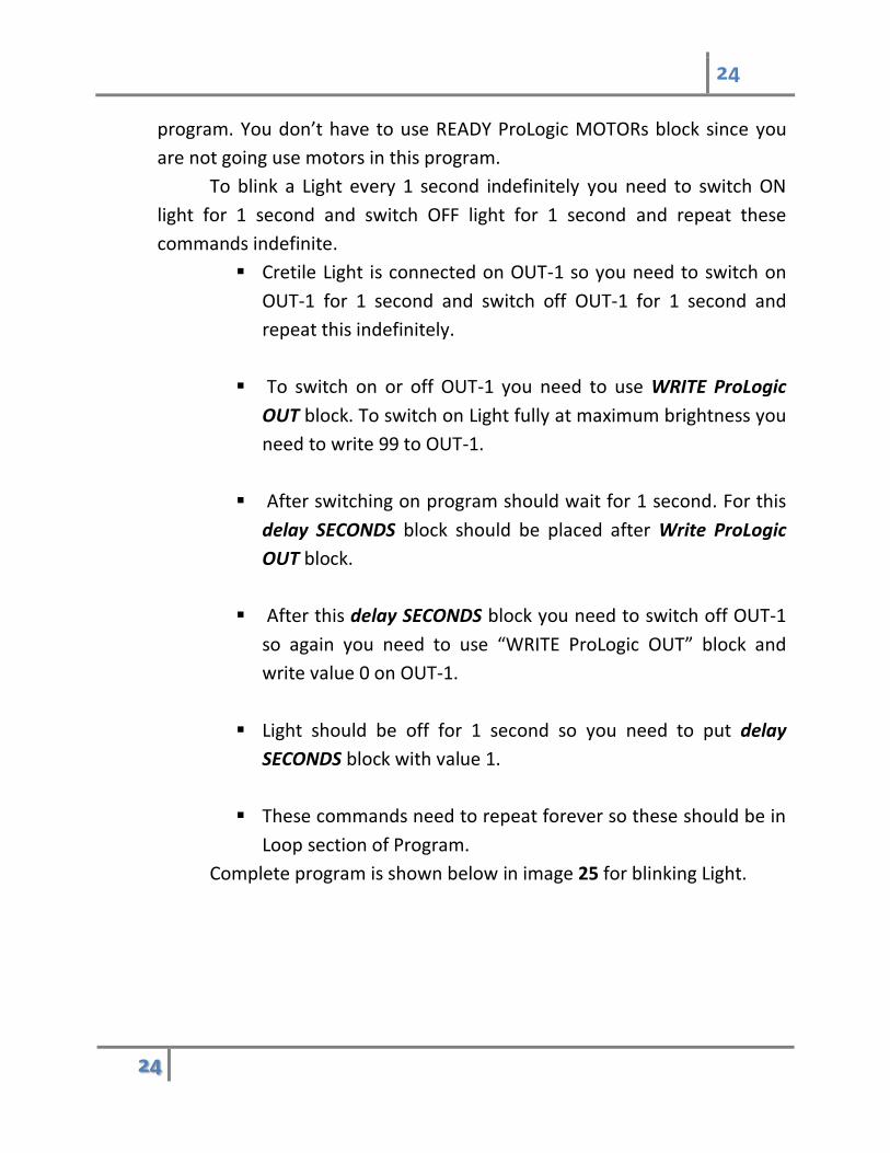
To blink a Light every 1 second indefinitely you need to switch ON
light for 1 second and switch OFF light for 1 second and repeat these
commands indefinite.
Cretile Light is connected on OUT-1 so you need to switch on
OUT-1 for 1 second and switch off OUT-1 for 1 second and
repeat this indefinitely.
To switch on or off OUT-1 you need to use WRITE ProLogic
OUT block. To switch on Light fully at maximum brightness you
need to write 99 to OUT-1.
After switching on program should wait for 1 second. For this
delay SECONDS block should be placed after Write ProLogic
OUT block.
After this delay SECONDS block you need to switch off OUT-1
so again you need to use “WRITE ProLogic OUT” block and
write value 0 on OUT-1.
Light should be off for 1 second so you need to put delay
SECONDS block with value 1.
These commands need to repeat forever so these should be in
Loop section of Program.
Complete program is shown below in image 25 for blinking Light.
25
25
Image 25
2. Setting speed of blinking using Dimmer and ProLogic
To control the speed of blink you need to change delay time in above
program. For faster blinking delay time should be smaller and slower
blinking delay time should be higher.
In previous program blink speed and hence delay time was constant.
If you want to change blink speed, delay time should change. Actual delay
time will be according to value set on Dimmer.
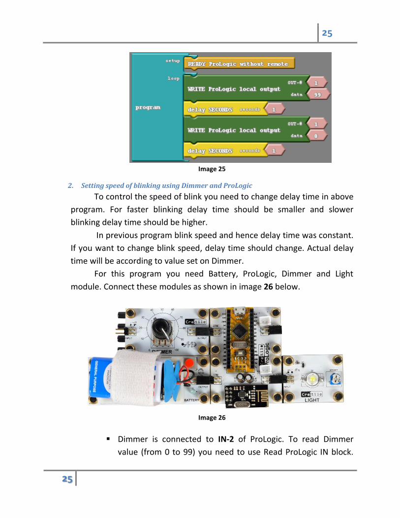
For this program you need Battery, ProLogic, Dimmer and Light
module. Connect these modules as shown in image 26 below.
Image 26
Dimmer is connected to IN-2 of ProLogic. To read Dimmer
value (from 0 to 99) you need to use Read ProLogic IN block.
26
26
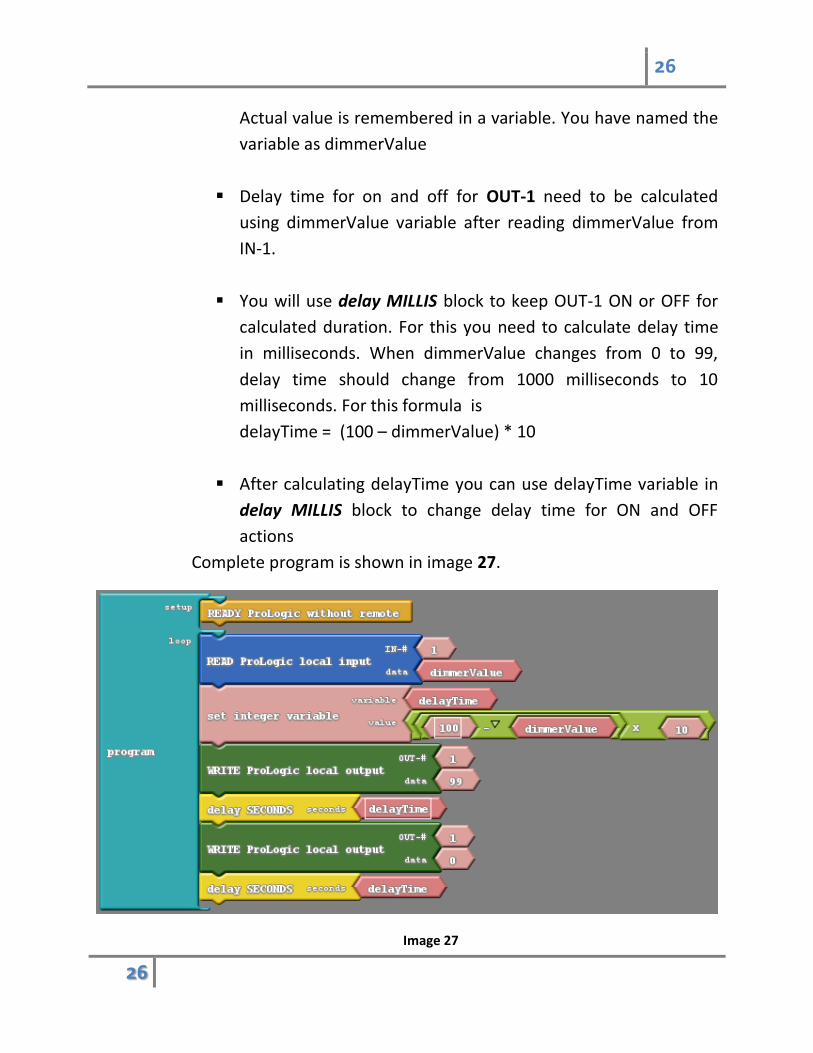
Actual value is remembered in a variable. You have named the
variable as dimmerValue
Delay time for on and off for OUT-1 need to be calculated
using dimmerValue variable after reading dimmerValue from
IN-1.
You will use delay MILLIS block to keep OUT-1 ON or OFF for
calculated duration. For this you need to calculate delay time
in milliseconds. When dimmerValue changes from 0 to 99,
delay time should change from 1000 milliseconds to 10
milliseconds. For this formula is
delayTime = (100 – dimmerValue) * 10
After calculating delayTime you can use delayTime variable in
delay MILLIS block to change delay time for ON and OFF
actions
Complete program is shown in image 27.
Image 27
27
27
1.7.2 ProLogic remote INputs and OUTputs
ProLogic advanced can communicate with Receiver and Transmitter. It
can write to receiver outputs OUT-1 to OUT-4 using WRITE ProLogic remote
OUT block. It can read from Transmitter inputs IN-1 to IN-4 using “READ
ProLogic remote IN” block.
These blocks are very similar to reading and writing local blocks as
described above.
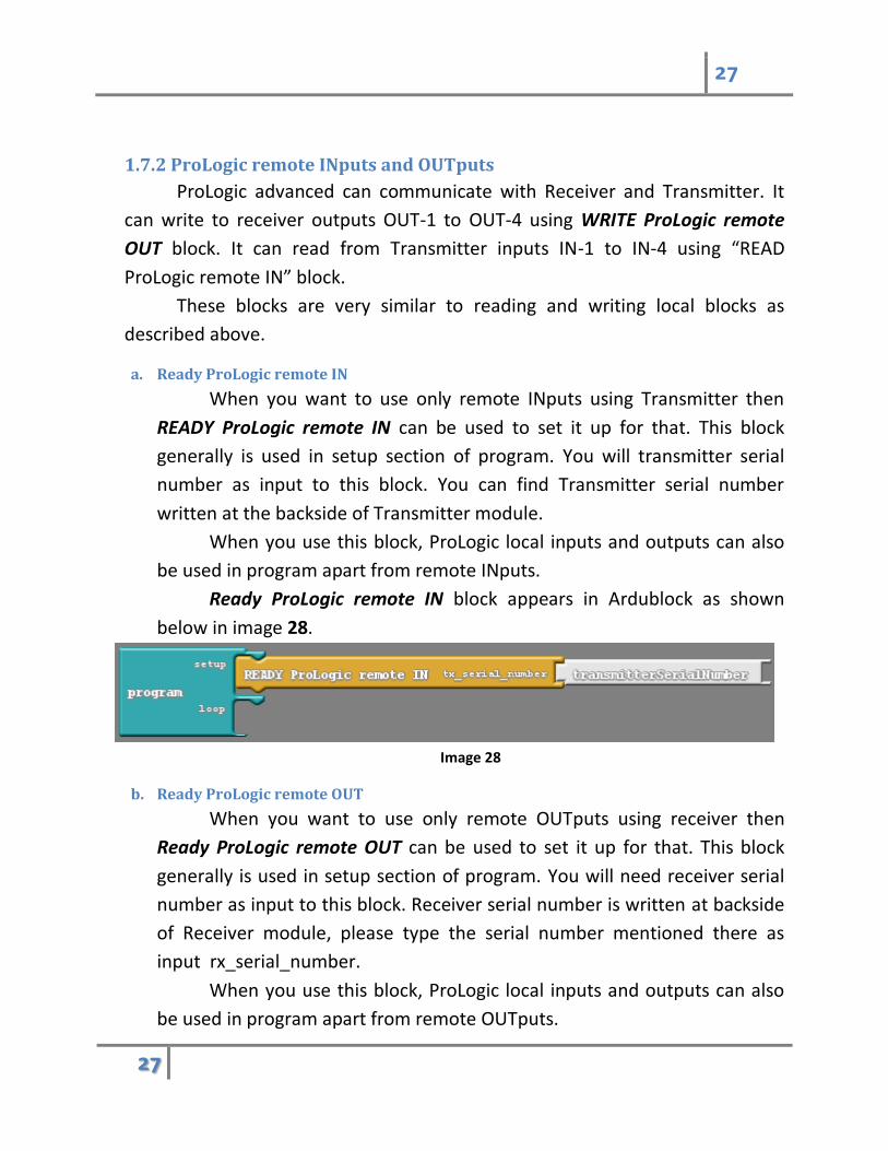
a. Ready ProLogic remote IN
When you want to use only remote INputs using Transmitter then
READY ProLogic remote IN can be used to set it up for that. This block
generally is used in setup section of program. You will transmitter serial
number as input to this block. You can find Transmitter serial number
written at the backside of Transmitter module.
When you use this block, ProLogic local inputs and outputs can also
be used in program apart from remote INputs.
Ready ProLogic remote IN block appears in Ardublock as shown
below in image 28.
Image 28
b. Ready ProLogic remote OUT
When you want to use only remote OUTputs using receiver then
Ready ProLogic remote OUT can be used to set it up for that. This block
generally is used in setup section of program. You will need receiver serial
number as input to this block. Receiver serial number is written at backside
of Receiver module, please type the serial number mentioned there as
input rx_serial_number.
When you use this block, ProLogic local inputs and outputs can also
be used in program apart from remote OUTputs.
28
28
Ready ProLogic remote OUT block appears in Ardublock as shown
below in image 29.
Image 29
c. Ready ProLogic remote IN & OUT
When you want to use remote INputs as well as OUTputs using
Transmitter & Receiver module then Ready ProLogic remote IN & OUT can
be used to setup ProLogic. This block generally is used in setup section of
program.
When you use this block, ProLogic local inputs and outputs can also
be used in program apart from remote OUTputs.
Ready ProLogic remote IN & OUT block appears in Ardublock as
shown below in image 30.
Image 30
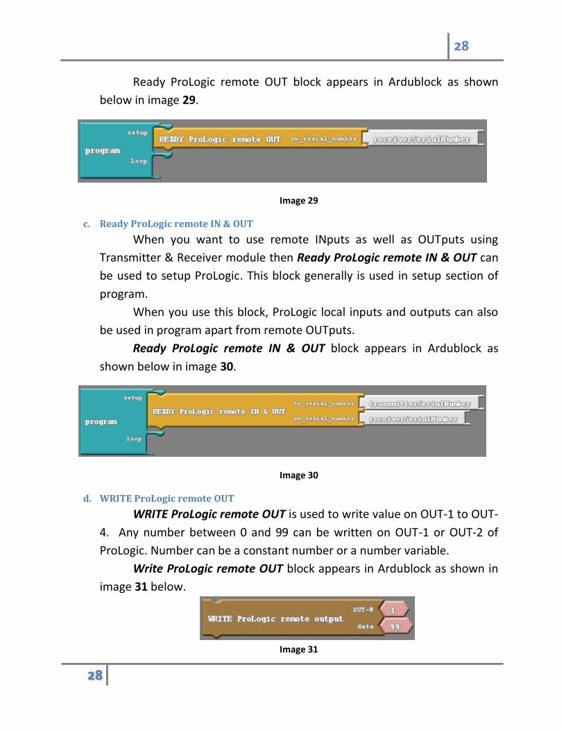
d. WRITE ProLogic remote OUT
WRITE ProLogic remote OUT is used to write value on OUT-1 to OUT-
4. Any number between 0 and 99 can be written on OUT-1 or OUT-2 of
ProLogic. Number can be a constant number or a number variable.
Write ProLogic remote OUT block appears in Ardublock as shown in
image 31 below.
Image 31
29
29
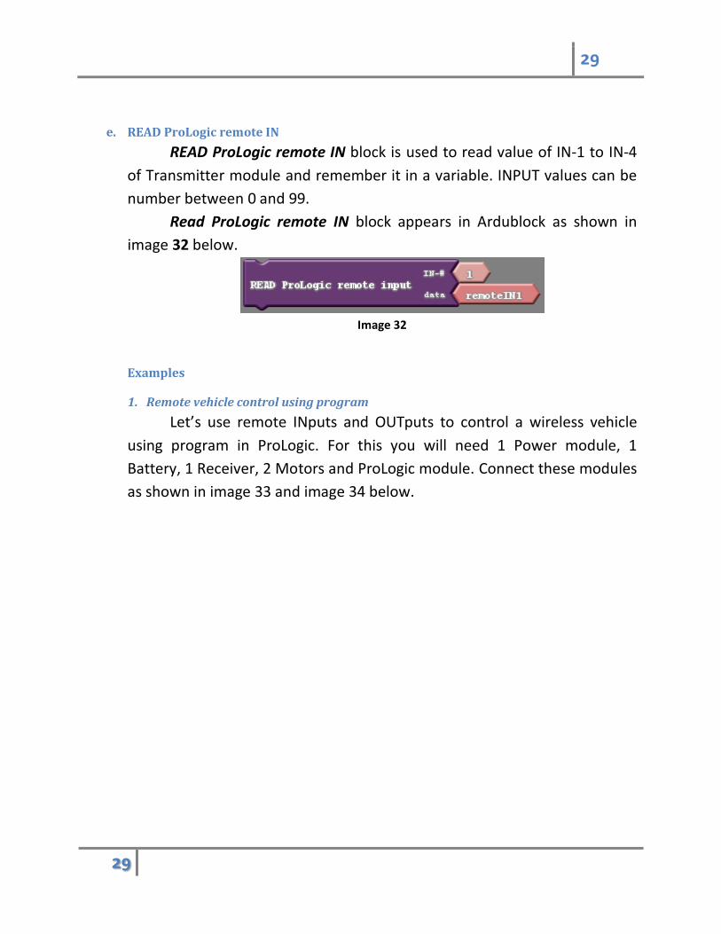
e. READ ProLogic remote IN
READ ProLogic remote IN block is used to read value of IN-1 to IN-4
of Transmitter module and remember it in a variable. INPUT values can be
number between 0 and 99.
Read ProLogic remote IN block appears in Ardublock as shown in
image 32 below.
Image 32
Examples
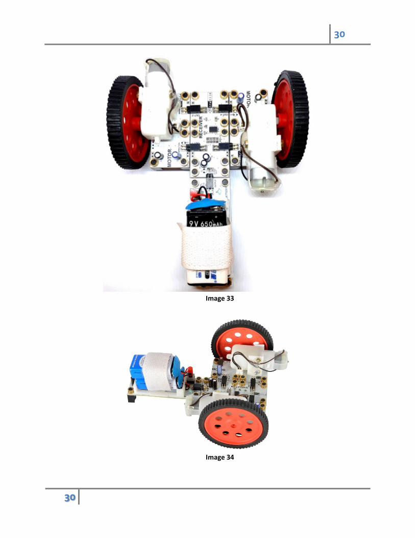
1. Remote vehicle control using program
Let’s use remote INputs and OUTputs to control a wireless vehicle
using program in ProLogic. For this you will need 1 Power module, 1
Battery, 1 Receiver, 2 Motors and ProLogic module. Connect these modules
as shown in image 33 and image 34 below.
30
30
Image 33
Image 34
31
31
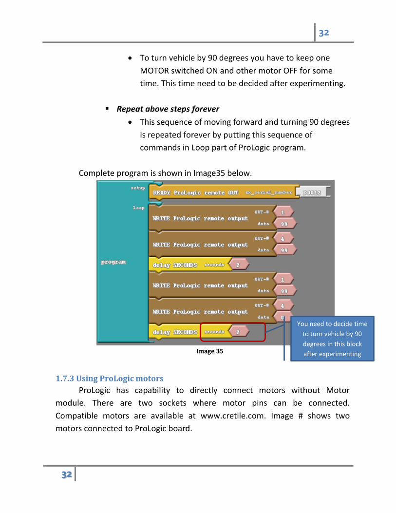
Let’s write a program which
Make ProLogic ready for writing remote OUTputs on receiver
Moves vehicle forward for 3 seconds
Turns vehicle by 90 degrees and moves forward vehicle for 3
seconds
Repeats this indefinitely.
Make ProLogic Ready to control remote OUTputs
You will need receiver’s serial number to initialize ProLogic for
communication with receiver and control its OUTputs. Serial
number of receiver and transmitter is written at the back of
Transmitter and Receiver. Please check and use the serial
number mentioned there in block for making ProLogic ready
with remote OUT block as described in section 1.7.2-b.
Move vehicle forward
To move vehicle forward you have to rotate both motors
in same direction. Motors are connected to receiver
facing opposite direction to each other. Hence to rotate
both motors in same direction one of motor direction
should be set opposite to other.
Speed control of MOTOR-1 connects to OUT-2 of
receiver
Speed control of MOTOR-2 is connected to OUT-4 of
receiver.
To turn vehicle you have to write 99 on remote OUT-2
and write 0 on remote OUT-4 for some time.
Turn Vehicle by 90 degrees
32
32
To turn vehicle by 90 degrees you have to keep one
MOTOR switched ON and other motor OFF for some
time. This time need to be decided after experimenting.
Repeat above steps forever
This sequence of moving forward and turning 90 degrees
is repeated forever by putting this sequence of
commands in Loop part of ProLogic program.
Complete program is shown in Image35 below.
Image 35
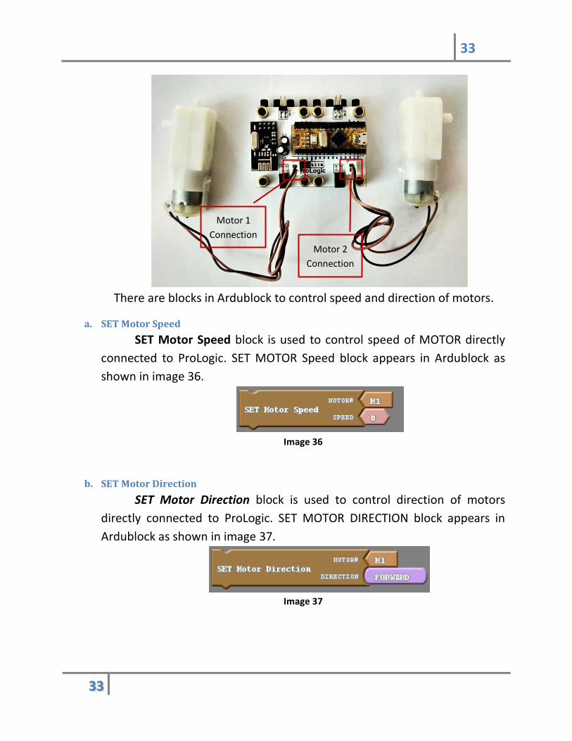
1.7.3 Using ProLogic motors
ProLogic has capability to directly connect motors without Motor
module. There are two sockets where motor pins can be connected.
Compatible motors are available at www.cretile.com. Image # shows two
motors connected to ProLogic board.
You need to decide time
to turn vehicle by 90
degrees in this block
after experimenting
33
33
There are blocks in Ardublock to control speed and direction of motors.
a. SET Motor Speed
SET Motor Speed block is used to control speed of MOTOR directly
connected to ProLogic. SET MOTOR Speed block appears in Ardublock as
shown in image 36.
Image 36
b. SET Motor Direction
SET Motor Direction block is used to control direction of motors
directly connected to ProLogic. SET MOTOR DIRECTION block appears in
Ardublock as shown in image 37.
Image 37
Motor 1
Connection
Motor 2
Connection
34
34
Part II
2. Developing ProLogic App on Android phone
2.1 Introduction
App Inventor is a tool by MIT which provides Scratch like graphical user
interface to develop Android application. Cretile provides extension in App
Inventor for communicating with ProLogic using Android phone’s USB port. This
communication works only when phone has USB-OTG support.
ProLogic local INputs and remote INputs are sent to Android phone,
Android phone then can read these values. Android phone can send values of
ProLogic local OUTputs and remote OUTputs over USB. In ProLogic program
you can choose to write values sent by Android phone on respective OUTputs.
There are blocks provided in App Inventor as well as Ardublock for this
communication. In following sections you will learn use of these blocks for
communication between Android Phone and ProLogic.
2.2 Developing Android Application for ProLogic using App Inventor
AppInventor runs in browser. There are few versions of App Inventor
available online.
1. http://ai2.appinventor.mit.edu/
2. http://gold.appybuilder.com
First version is from MIT who have developed App Inventor. Second
version is external version with few enhancements. You can use any version
according to your preference.
We will use ai2.appinventor.mit.edu.
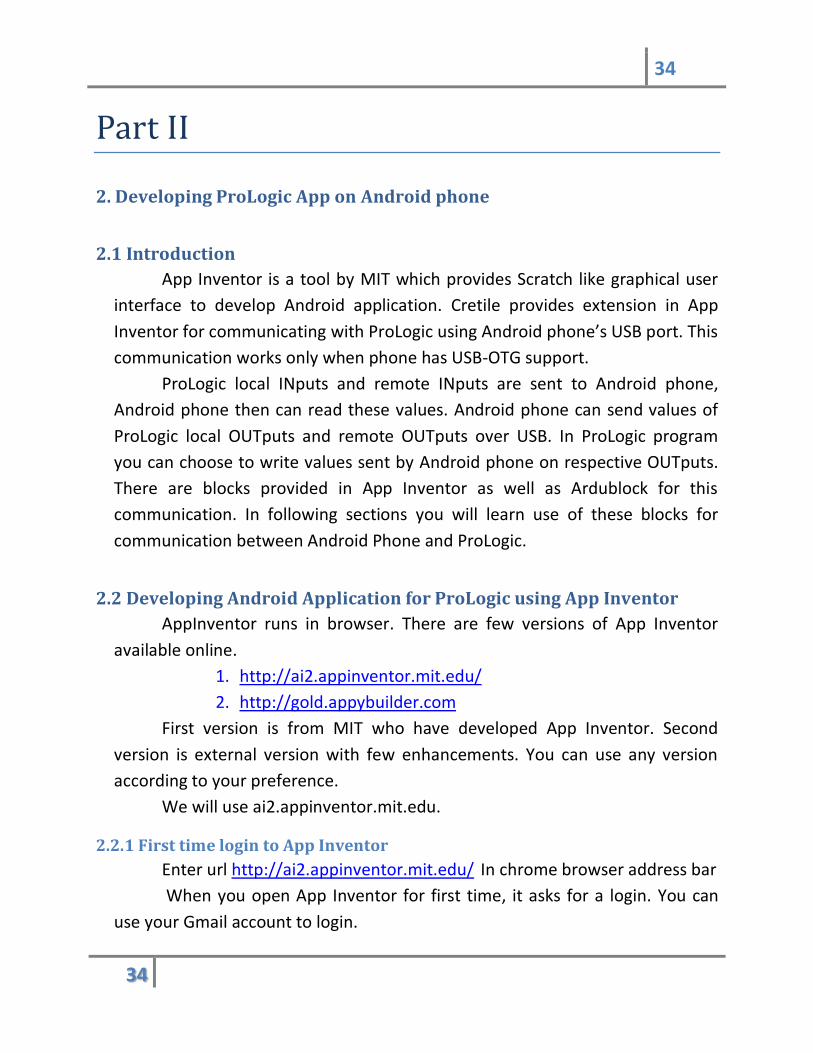
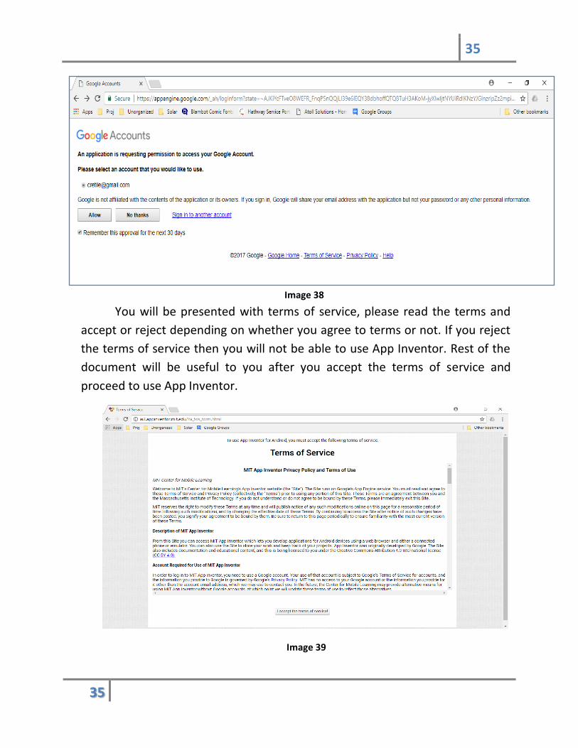
2.2.1 First time login to App Inventor
Enter url http://ai2.appinventor.mit.edu/ In chrome browser address bar
When you open App Inventor for first time, it asks for a login. You can
use your Gmail account to login.
35
35
Image 38
You will be presented with terms of service, please read the terms and
accept or reject depending on whether you agree to terms or not. If you reject
the terms of service then you will not be able to use App Inventor. Rest of the
document will be useful to you after you accept the terms of service and
proceed to use App Inventor.
Image 39
36
36
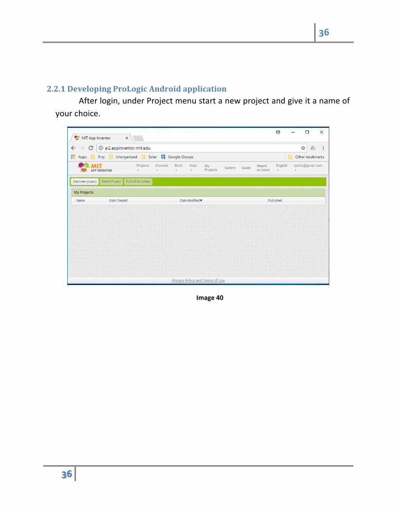
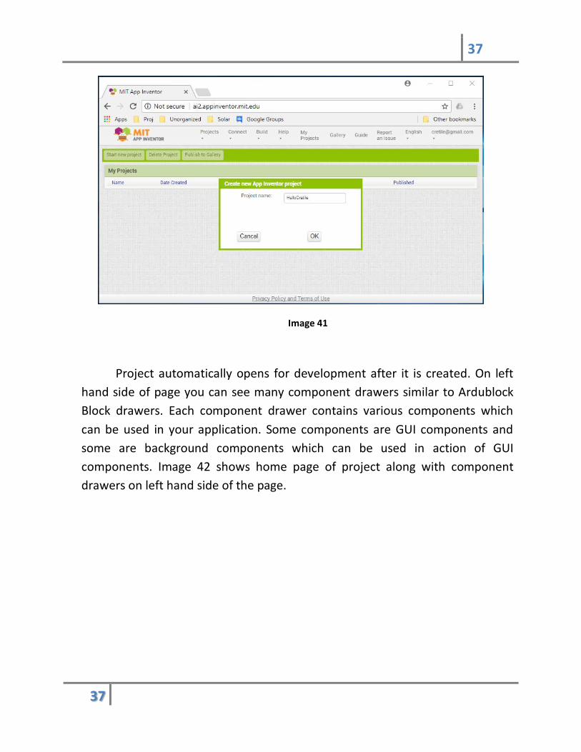
2.2.1 Developing ProLogic Android application
After login, under Project menu start a new project and give it a name of
your choice.
Image 40
37
37
Image 41
Project automatically opens for development after it is created. On left
hand side of page you can see many component drawers similar to Ardublock
Block drawers. Each component drawer contains various components which
can be used in your application. Some components are GUI components and
some are background components which can be used in action of GUI
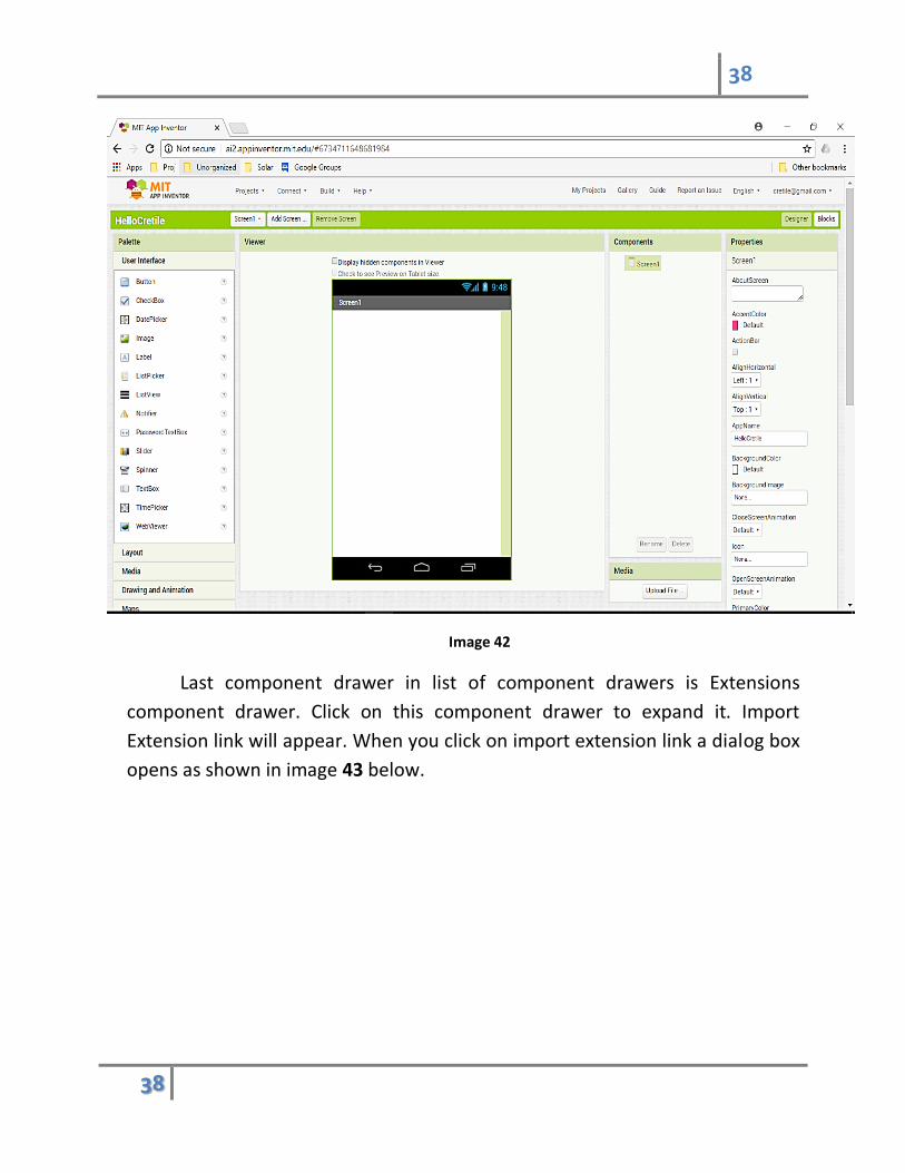
components. Image 42 shows home page of project along with component
drawers on left hand side of the page.
38
38
Image 42
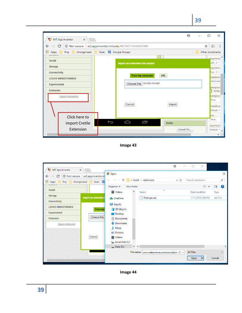
Last component drawer in list of component drawers is Extensions
component drawer. Click on this component drawer to expand it. Import
Extension link will appear. When you click on import extension link a dialog box
opens as shown in image 43 below.
39
39
Image 43
Image 44
Click here to
import Cretile
Extension
40
40
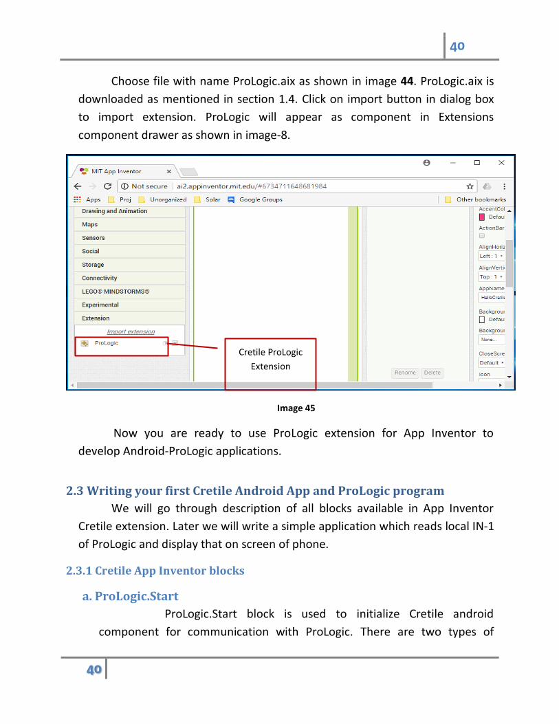
Choose file with name ProLogic.aix as shown in image 44. ProLogic.aix is
downloaded as mentioned in section 1.4. Click on import button in dialog box
to import extension. ProLogic will appear as component in Extensions
component drawer as shown in image-8.
Image 45
Now you are ready to use ProLogic extension for App Inventor to
develop Android-ProLogic applications.
2.3 Writing your first Cretile Android App and ProLogic program
We will go through description of all blocks available in App Inventor
Cretile extension. Later we will write a simple application which reads local IN-1
of ProLogic and display that on screen of phone.
2.3.1 Cretile App Inventor blocks
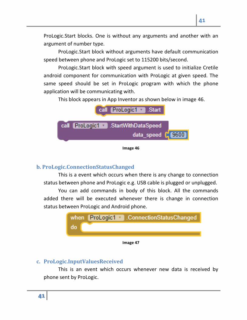
a. ProLogic.Start
ProLogic.Start block is used to initialize Cretile android
component for communication with ProLogic. There are two types of
Cretile ProLogic
Extension
41
41
ProLogic.Start blocks. One is without any arguments and another with an
argument of number type.
ProLogic.Start block without arguments have default communication
speed between phone and ProLogic set to 115200 bits/second.
ProLogic.Start block with speed argument is used to initialize Cretile
android component for communication with ProLogic at given speed. The
same speed should be set in ProLogic program with which the phone
application will be communicating with.
This block appears in App Inventor as shown below in image 46.
Image 46
b. ProLogic.ConnectionStatusChanged
This is a event which occurs when there is any change to connection
status between phone and ProLogic e.g. USB cable is plugged or unplugged.
You can add commands in body of this block. All the commands
added there will be executed whenever there is change in connection
status between ProLogic and Android phone.
Image 47
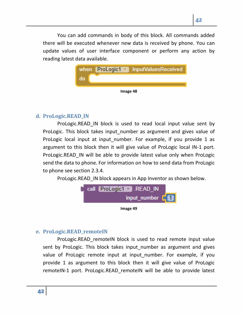
c. ProLogic.InputValuesReceived
This is an event which occurs whenever new data is received by
phone sent by ProLogic.
42
42
You can add commands in body of this block. All commands added
there will be executed whenever new data is received by phone. You can
update values of user interface component or perform any action by
reading latest data available.
Image 48
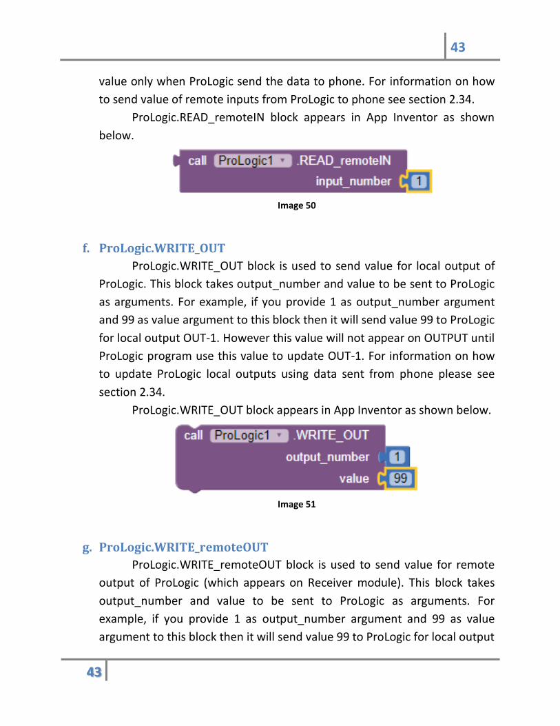
d. ProLogic.READ_IN
ProLogic.READ_IN block is used to read local input value sent by
ProLogic. This block takes input_number as argument and gives value of
ProLogic local input at input_number. For example, if you provide 1 as
argument to this block then it will give value of ProLogic local IN-1 port.
ProLogic.READ_IN will be able to provide latest value only when ProLogic
send the data to phone. For information on how to send data from ProLogic
to phone see section 2.3.4.
ProLogic.READ_IN block appears in App Inventor as shown below.
Image 49
e. ProLogic.READ_remoteIN
ProLogic.READ_remoteIN block is used to read remote input value
sent by ProLogic. This block takes input_number as argument and gives
value of ProLogic remote input at input_number. For example, if you
provide 1 as argument to this block then it will give value of ProLogic
remoteIN-1 port. ProLogic.READ_remoteIN will be able to provide latest
43
43
value only when ProLogic send the data to phone. For information on how
to send value of remote inputs from ProLogic to phone see section 2.34.
ProLogic.READ_remoteIN block appears in App Inventor as shown
below.
Image 50
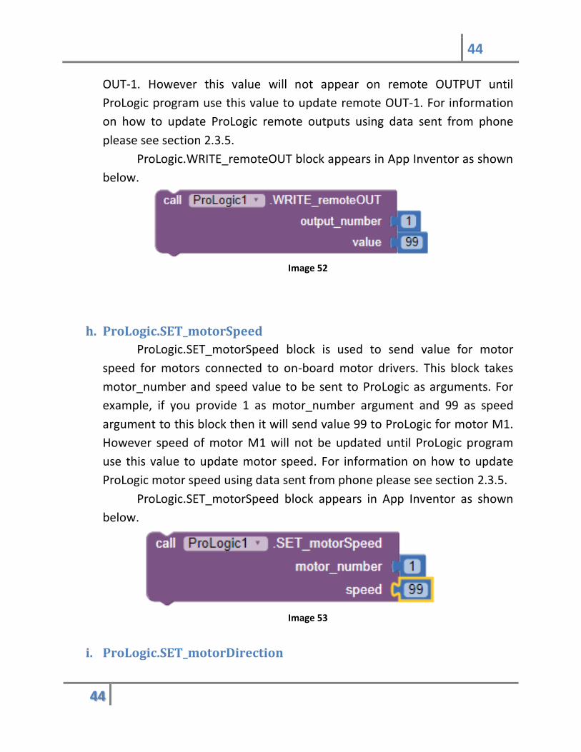
f. ProLogic.WRITE_OUT
ProLogic.WRITE_OUT block is used to send value for local output of
ProLogic. This block takes output_number and value to be sent to ProLogic
as arguments. For example, if you provide 1 as output_number argument
and 99 as value argument to this block then it will send value 99 to ProLogic
for local output OUT-1. However this value will not appear on OUTPUT until
ProLogic program use this value to update OUT-1. For information on how
to update ProLogic local outputs using data sent from phone please see
section 2.34.
ProLogic.WRITE_OUT block appears in App Inventor as shown below.
Image 51
g. ProLogic.WRITE_remoteOUT
ProLogic.WRITE_remoteOUT block is used to send value for remote
output of ProLogic (which appears on Receiver module). This block takes
output_number and value to be sent to ProLogic as arguments. For
example, if you provide 1 as output_number argument and 99 as value
argument to this block then it will send value 99 to ProLogic for local output
44
44
OUT-1. However this value will not appear on remote OUTPUT until
ProLogic program use this value to update remote OUT-1. For information
on how to update ProLogic remote outputs using data sent from phone
please see section 2.3.5.
ProLogic.WRITE_remoteOUT block appears in App Inventor as shown
below.
Image 52
h. ProLogic.SET_motorSpeed
ProLogic.SET_motorSpeed block is used to send value for motor
speed for motors connected to on-board motor drivers. This block takes
motor_number and speed value to be sent to ProLogic as arguments. For
example, if you provide 1 as motor_number argument and 99 as speed
argument to this block then it will send value 99 to ProLogic for motor M1.
However speed of motor M1 will not be updated until ProLogic program
use this value to update motor speed. For information on how to update
ProLogic motor speed using data sent from phone please see section 2.3.5.
ProLogic.SET_motorSpeed block appears in App Inventor as shown
below.
Image 53
i. ProLogic.SET_motorDirection

45
45
ProLogic.SET_motorDirection block is used to send value of motor
direction for motors connected to on-board motor drivers. This block takes
motor_number and forward value to be sent to ProLogic as arguments. For
example, if you provide 1 as motor_number argument and forward is set to
true then it will send direction forward to ProLogic for motor M1. However
direction of motor M1 will not change until ProLogic program uses this
value to update motor direction. For information on how to update
ProLogic motor direction using data sent from phone please see section
2.3.4.
ProLogic.SET_motorDirection block appears in App Inventor as
shown below.
Image 54
2.3.2 Setting up your Android phone
You need to install Android application provided by Cretile to enable
communication between ProLogic and Android application developed by
you. You don’t have to open the Cretile application as it automatically runs
in background when needed by Application developed by you in App
Inventor.
When you unzip Cretile.zip you will find CretileApp folder in unzipped
folder as highlighted in image below.
In this folder there will be Cretile.apk file present which need to be installed
on your android phone. To install this apk file you need to transfer this file
46
46
to your android phone. Please copy this file to Android phone Downloads
folder. Please use help on transferring data from PC to Android phone
provided on this link How to Transfer Files From Android to PC Using USB
Cable
Please enable installation of application from Unknown Sources to install
this application on your android phone. You can take help provided on this
link How to Install Apps from Unknown Sources in Android.
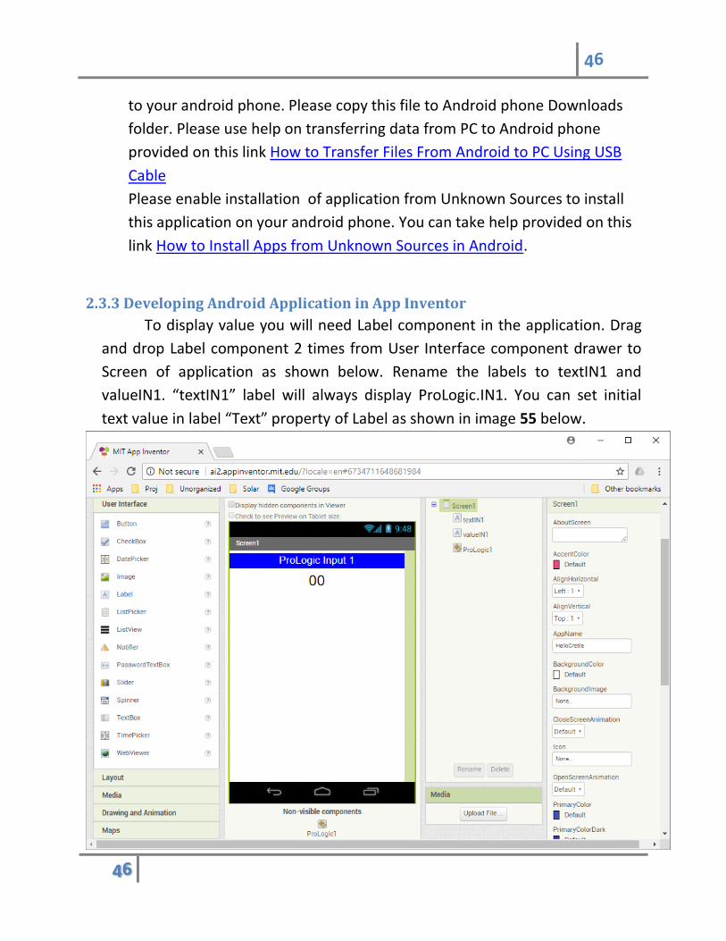
2.3.3 Developing Android Application in App Inventor
To display value you will need Label component in the application. Drag
and drop Label component 2 times from User Interface component drawer to
Screen of application as shown below. Rename the labels to textIN1 and
valueIN1. “textIN1” label will always display ProLogic.IN1. You can set initial
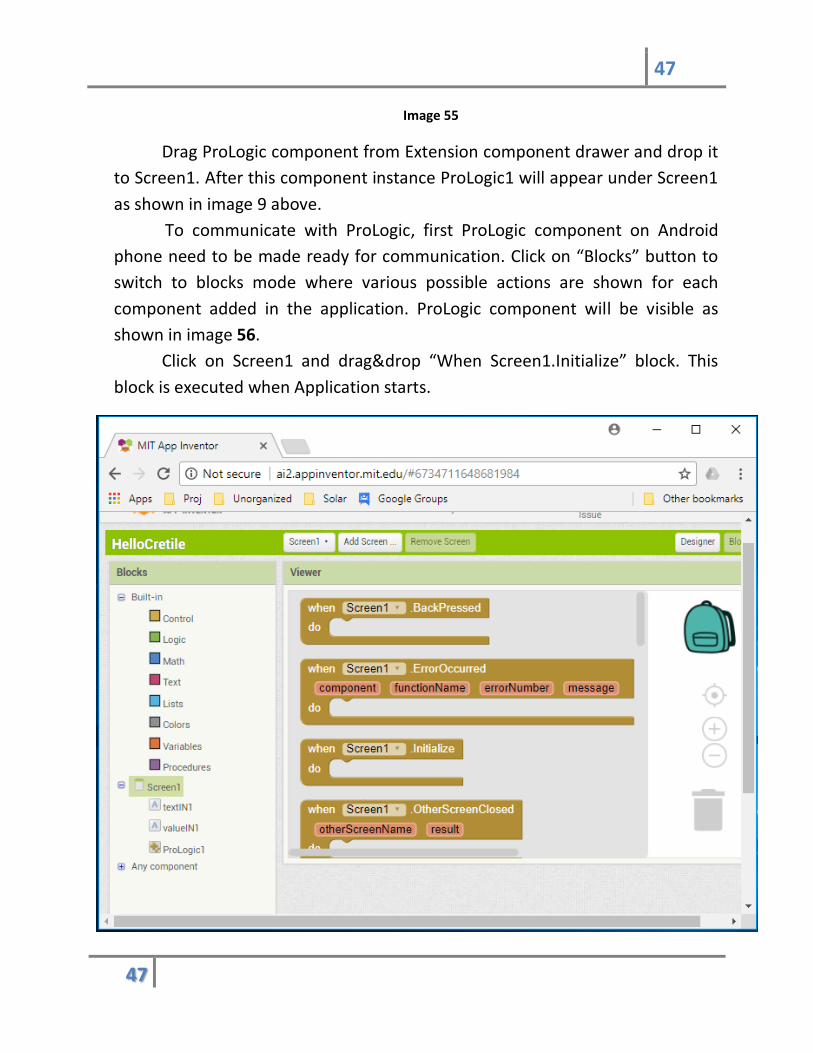
text value in label “Text” property of Label as shown in image 55 below.
47
47
Image 55
Drag ProLogic component from Extension component drawer and drop it
to Screen1. After this component instance ProLogic1 will appear under Screen1
as shown in image 9 above.
To communicate with ProLogic, first ProLogic component on Android
phone need to be made ready for communication. Click on “Blocks” button to
switch to blocks mode where various possible actions are shown for each
component added in the application. ProLogic component will be visible as
shown in image 56.
Click on Screen1 and drag&drop “When Screen1.Initialize” block. This
block is executed when Application starts.

48
48
Image 56
Click on ProLogic component and all blocks related to ProLogic
component will be visible as shown below in image 57.
Select ProLogic1.Start block and add it in event Screen1.Initialize. This
will initialize ProLogic Android communication component with default data
speed of 115200 bits per second.
Image 57

49
49
Image 58
50
50
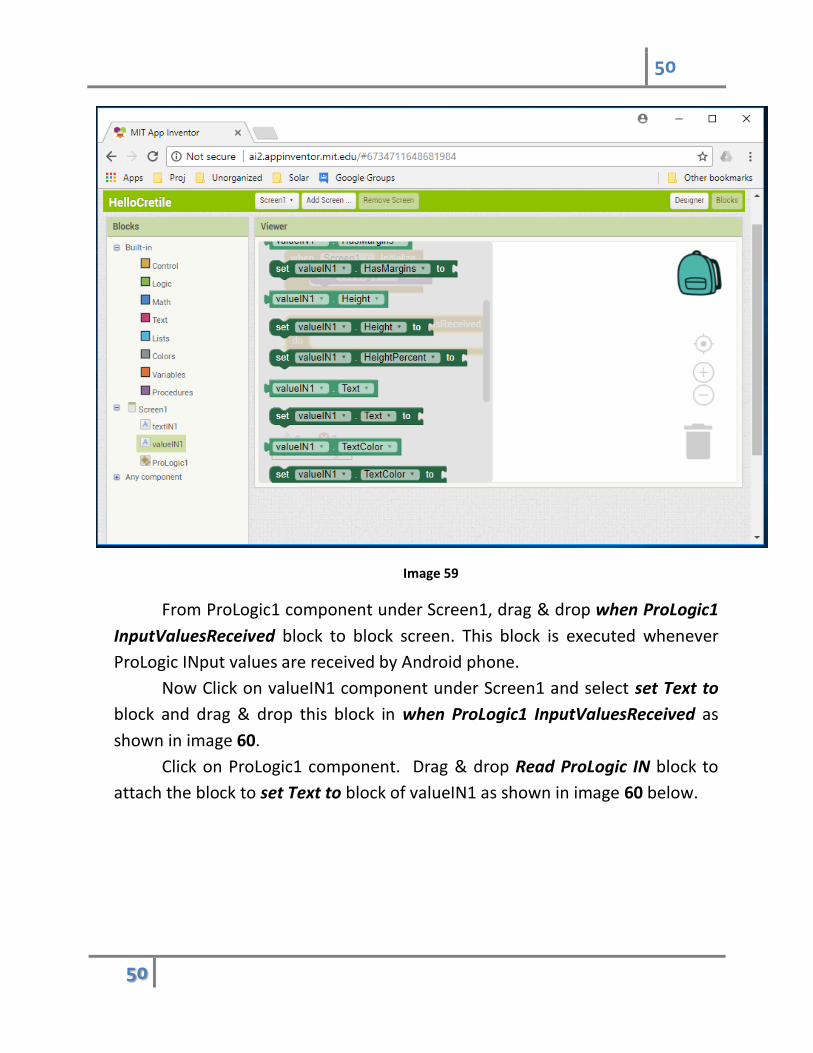
Image 59
From ProLogic1 component under Screen1, drag & drop when ProLogic1
InputValuesReceived block to block screen. This block is executed whenever
ProLogic INput values are received by Android phone.
Now Click on valueIN1 component under Screen1 and select set Text to
block and drag & drop this block in when ProLogic1 InputValuesReceived as
shown in image 60.
Click on ProLogic1 component. Drag & drop Read ProLogic IN block to
attach the block to set Text to block of valueIN1 as shown in image 60 below.
51
51
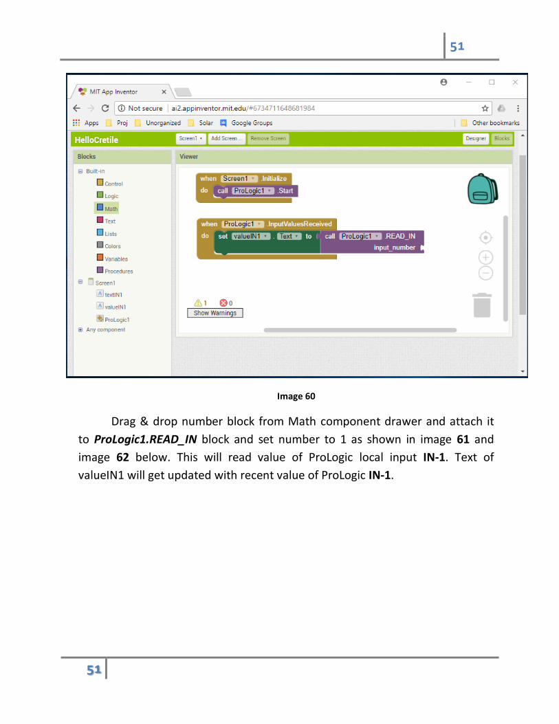
Image 60
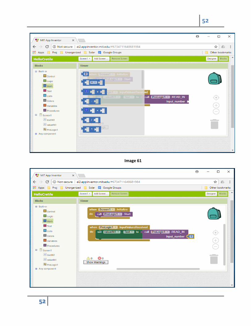
Drag & drop number block from Math component drawer and attach it
to ProLogic1.READ_IN block and set number to 1 as shown in image 61 and
image 62 below. This will read value of ProLogic local input IN-1. Text of
valueIN1 will get updated with recent value of ProLogic IN-1.
52
52
Image 61
53
53
Image 62
2.3.4 Installing application on android phone
Please see this video which explains how to download and install apk
file for your application. You can follow procedure shown in the video to install
android application that you have developed on your USB-OTG capable android
phone.
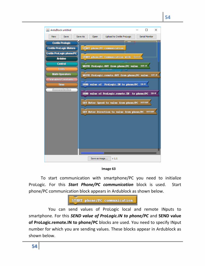
2.3.5 Blocks for Mobile/PC communication in Ardublock
Ardublock for Cretile has block drawer named Cretile phone/PC
communication. This block drawer contains blocks to send data to phone/PC
and use data from Android phone/PC.
Open Arduino for Cretile as explained in section 1.5.1. There is Block
drawer named Cretile ProLogic Phone/PC which provides all the blocks needed
for communication between phone/PC and ProLogic (using USB cable).
54
54
Image 63
To start communication with smartphone/PC you need to initialize
ProLogic. For this Start Phone/PC communication block is used. Start
phone/PC communication block appears in Ardublock as shown below.
You can send values of ProLogic local and remote INputs to
smartphone. For this SEND value of ProLogic.IN to phone/PC and SEND value
of ProLogic.remote.IN to phone/PC blocks are used. You need to specify INput
number for which you are sending values. These blocks appear in Ardublock as
shown below.

55
55
Even though ProLogic receives data from phone/PC for values of
OUTputs automatically always, those are not directly written on OUTputs. You
can choose to write values of local and remote OUT whenever you want in
program. You can choose to update one or more OUTputs when required. This
can be done by WRITE ProLogic.OUT from phone/PC value and WRITE
ProLogic.remote.OUT from phone/PC blocks. These blocks need output
number as parameter. These blocks appear in Ardublock as shown below.
Similar to local and remote OUTputs, on-board Motor drivers in ProLogic
can be controlled from Android application. Similar to local and remote OUTput
values Motor speed and direction values are received by ProLogic when you
use Start phone/PC communication block. You can choose to update motor
speeds and direction using the received values whenever you want in your
program. This is achieved by using SET Motor speed to value from phone/PC
and SET Motor direction to value from phone/PC.
2.3.6 Developing ProLogic Program to work with Android Application
Android Application developed in section 2.3.1 need value of IN-1 to be
sent from ProLogic to the phone. You need to develop and upload program on
ProLogic which will do this job.
ProLogic program should do following
56
56
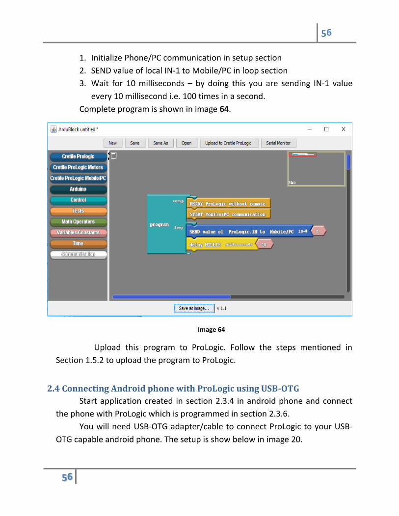
1. Initialize Phone/PC communication in setup section
2. SEND value of local IN-1 to Mobile/PC in loop section
3. Wait for 10 milliseconds – by doing this you are sending IN-1 value
every 10 millisecond i.e. 100 times in a second.
Complete program is shown in image 64.
Image 64
Upload this program to ProLogic. Follow the steps mentioned in
Section 1.5.2 to upload the program to ProLogic.
2.4 Connecting Android phone with ProLogic using USB-OTG
Start application created in section 2.3.4 in android phone and connect
the phone with ProLogic which is programmed in section 2.3.6.
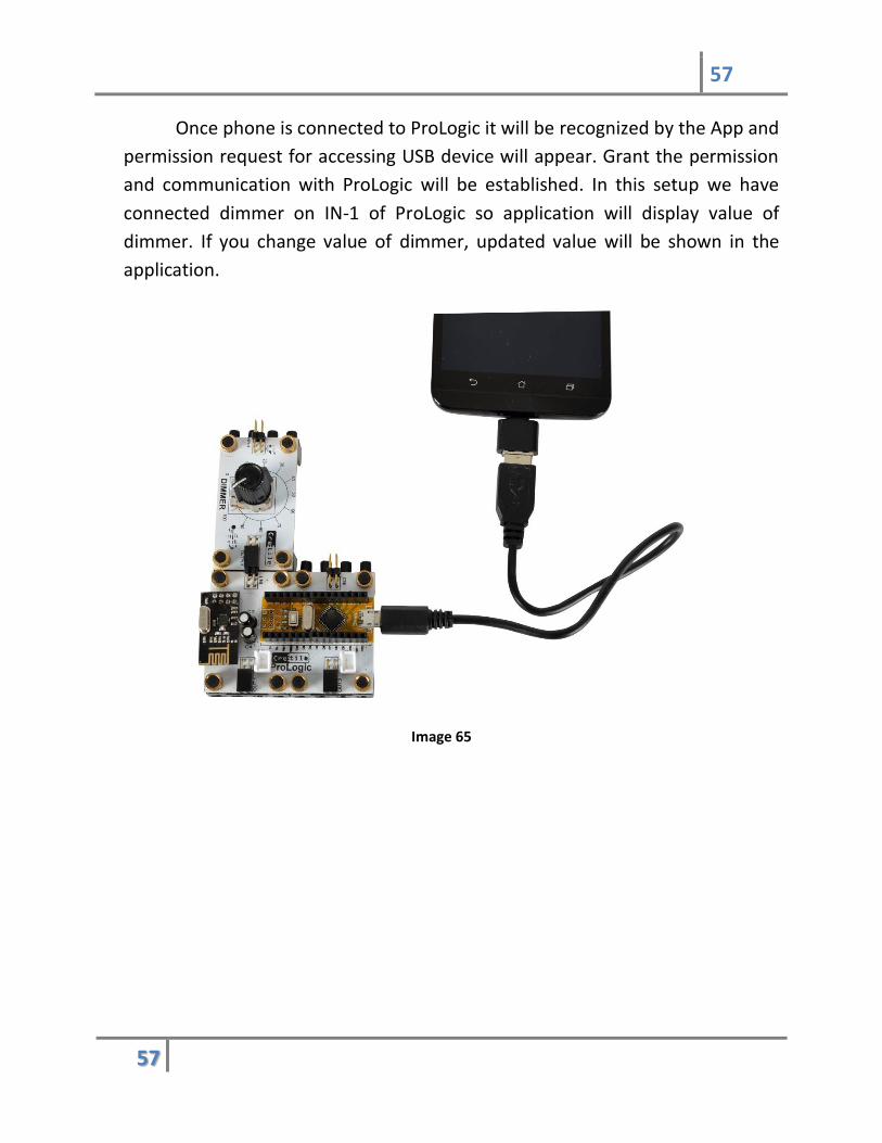
You will need USB-OTG adapter/cable to connect ProLogic to your USB-
OTG capable android phone. The setup is show below in image 20.
57
57
Once phone is connected to ProLogic it will be recognized by the App and
permission request for accessing USB device will appear. Grant the permission
and communication with ProLogic will be established. In this setup we have
connected dimmer on IN-1 of ProLogic so application will display value of
dimmer. If you change value of dimmer, updated value will be shown in the
application.
Image 65