Embed Size (px)
Citation preview


22101-
7-22-04TABLE OF CONTENTS
HT40KX (HRAAAA-00**)SUPERCEDES
TITLE DATE SECTION
TABLE OF CONTENTSHT40KX / Std Ctrl / No Eng Ctrls (HRAAAA-00**)
SECTION 100 DESCRIPTION & SPECIFICATIONS22343 INSTALLATION DIMENSIONS18353 MOUNTING DIMENSIONS - BASE PLATE22341 CAPACITY CHART - HT40KX
SECTION 150 SAFETY15394 VEHICLE & CRANE ELECTRICAL HAZARD INFORMATION920612 SAFETY & HAZARDS - GENERAL19217 WINCH SAFETY WARNINGS22489 DECAL PLACEMENT
SECTION 200 INSTALLATION20697 CRANE INSTALLATION (PAGE 1 OF 2)22344B CRANE INSTALLATION (PAGE 2 OF 2)22345A CRANE OPERATION & MAINTENANCE INSTRUCTIONS (PAGE 1 OF 3)22345B CRANE OPERATION & MAINTENANCE INSTRUCTIONS (PAGE 2 OF 3)22345C CRANE OPERATION & MAINTENANCE INSTRUCTIONS (PAGE 3 OF 3)22328 SAFETY SHUTOFF INSTRUCTIONS22335 PTO INSTALLATION20698 COMPARTMENT DRAWING17831 INSTALLATION & MOUNTING DIMENSIONS - 17350 PEDESTAL22245 WIRE ROPE INSTALLATION
SECTION 300 MAINTENANCE & SERVICE14544 ADJUSTMENT OF WORM HEIGHT AND BACKLASH14553 ADJUSTMENT OF ROTATION WORM END PLAY
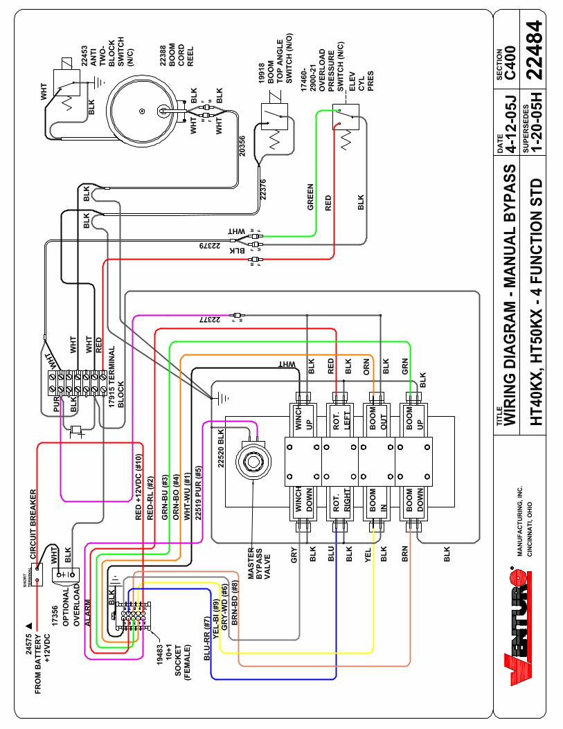
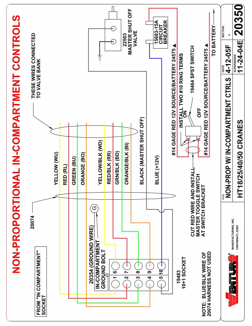
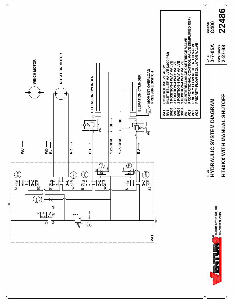
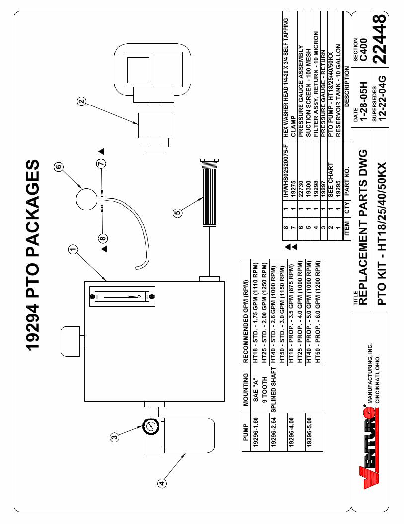
SECTION 400 REPLACEMENT PARTS22346 HT40/50KX CRANE REPLACEMENT PARTS DRAWING22517 HT40/50KX CRANE REPLACEMENT PARTS LIST22518 HT40/50KX CRANE FASTENER LIST24571 24550 BOOM REPLACEMENT PARTS DRAWING24572 24550 BOOM REPLACEMENT PARTS LIST20699 HYDRAULIC SYSTEM COMPONENTS REPLACEMENT PARTS DRAWING20930 HYDRAULIC SYSTEM COMPONENTS REPLACEMENT PARTS LIST22484 ELECTRICAL SCHEMATIC - STANDARD (NON-PROPORTIONAL)20350 ELECTRICAL SCHEMATIC - NON-PROP W/ IN-COMP CONTROLS22486 HYDRAULIC SYSTEM SCHEMATIC - STANDARD (NON-PROP) HT40KX22078 22062 REPLACEMENT PARTS DRAWING22084 22066 RADIO REMOTE REPLACEMENT PARTS DWG22684 22685 ANTI-TWO-BLOCK SYSTEM (STANDARD LEFT SIDE MOUNT)22449 22450 ANTI-TWO-BLOCK SYSTEM (OPTIONAL RIGHT SIDE MOUNT)22448 19294 PTO PACKAGE
CINCINNATI, OHIOMFG., INC.
-


SECTION 100
DESCRIPTION
&
SPECIFICATIONS
7607100A


SECTION 150
SAFETY
8604150
15394C150
5-13-97G
5-15-02HINSTALLATION DWG
ET & HT CRANE SERIESSUPERCEDES
TITLE DATE SECTION
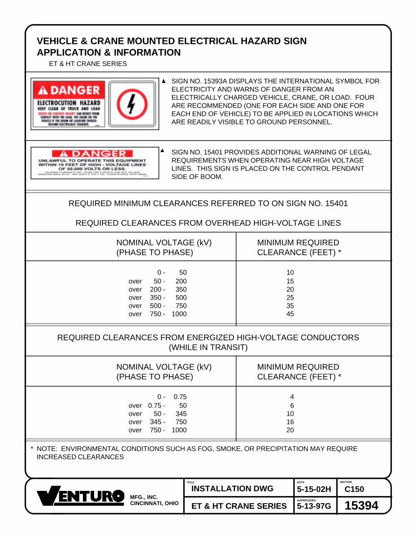
VEHICLE & CRANE MOUNTED ELECTRICAL HAZARD SIGNAPPLICATION & INFORMATION
ET & HT CRANE SERIES
SIGN NO. 15393A DISPLAYS THE INTERNATIONAL SYMBOL FORELECTRICITY AND WARNS OF DANGER FROM ANELECTRICALLY CHARGED VEHICLE, CRANE, OR LOAD. FOURARE RECOMMENDED (ONE FOR EACH SIDE AND ONE FOREACH END OF VEHICLE) TO BE APPLIED IN LOCATIONS WHICHARE READILY VISIBLE TO GROUND PERSONNEL.
SIGN NO. 15401 PROVIDES ADDITIONAL WARNING OF LEGALREQUIREMENTS WHEN OPERATING NEAR HIGH VOLTAGELINES. THIS SIGN IS PLACED ON THE CONTROL PENDANTSIDE OF BOOM.
REQUIRED MINIMUM CLEARANCES REFERRED TO ON SIGN NO. 15401
REQUIRED CLEARANCES FROM OVERHEAD HIGH-VOLTAGE LINES
NOMINAL VOLTAGE (kV) MINIMUM REQUIRED(PHASE TO PHASE) CLEARANCE (FEET) *
0 - 50 10over 50 - 200 15over 200 - 350 20over 350 - 500 25over 500 - 750 35over 750 - 1000 45
REQUIRED CLEARANCES FROM ENERGIZED HIGH-VOLTAGE CONDUCTORS(WHILE IN TRANSIT)
NOMINAL VOLTAGE (kV) MINIMUM REQUIRED(PHASE TO PHASE) CLEARANCE (FEET) *
0 - 0.75 4over 0.75 - 50 6over 50 - 345 10over 345 - 750 16over 750 - 1000 20
* NOTE: ENVIRONMENTAL CONDITIONS SUCH AS FOG, SMOKE, OR PRECIPITATION MAY REQUIREINCREASED CLEARANCES
CINCINNATI, OHIOMFG., INC.

CRANE SAFETY AND HAZARDSHT25KX, HT40KX, HT50KX
CAUTIONS1. INSPECT VEHICLE AND CRANE, INCLUDING OPERATION, PRIOR TO USE DAILY.2. DO NOT USE THIS EQUIPMENT EXCEPT ON SOLID, LEVEL SURFACE WITH CRANE MOUNTED ON
FACTORY-RECOMMENDED TRUCK.3. BEFORE OPERATING THE CRANE, REFER TO MAXIMUM LOAD (CAPACITY) CHART ON CRANE FOR
OPERATING (LOAD) LIMITATIONS.4. DO NOT OPERATE, WALK, OR STAND BENEATH BOOM OR A SUSPENDED LOAD.5. ATTACH PENDANT CORD SUPPORT SNAP TO ATTACHMENT POINT BEFORE PLUGGING IN
PENDANT.6. UNPLUG PENDANT AND DISENGAGE PTO SYSTEM WHEN CRANE NOT IN USE.7. FOR TRAVEL, BOOM MUST BE IN STOWED POSITION.
DANGER• THIS CRANE IS NOT A PASSENGER LIFT• IT IS NOT DESIGNED OR INTENDED TO BE USED TO LIFT, SUPPORT, OR OTHERWISE TRANSPORT
PERSONNEL.
YOU MUST NOT OPERATE THIS CRANE UNLESS1. YOU HAVE BEEN TRAINED IN THE SAFE OPERATION OF THIS CRANE
AND2. YOU KNOW AND FOLLOW THE SAFETY AND OPERATING RECOMMENDATIONS CONTAINED IN THE
MANUFACTURER'S MANUALS, YOUR EMPLOYER'S WORK RULES, AND APPLICABLE GOVERNMENTREGULATIONS. AN UNTRAINED OPERATOR SUBJECTS HIMSELF AND OTHERS TO DEATH ORSERIOUS INJURY.
ELECTROCUTION HAZARD• THIS MACHINE IS NOT INSULATED.• MAINTAIN SAFE CLEARANCES FROM ELECTRICAL LINES AND APPARATUS.• YOU MUST ALLOW FOR BOOM SWAY, ROCK OR SAG, AND ELECTRICAL LINE AND LOADLINE
SWAYING.• THIS LIFTING DEVICE DOES NOT PROVIDE PROTECTION FROM CONTACT WITH OR PROXIMITY TO
AN ELECTRICALLY CHARGED CONDUCTOR.• YOU MUST MAINTAIN A CLEARANCE OF AT LEAST 10 FEET BETWEEN ANY PART OF THE CRANE,
LOADLINE, OR LOAD, AND ANY ELECTRICAL LINE OR APPARATUS CARRYING UP TO 50,000 VOLTS.ADDITIONAL CLEARANCE IS REQUIRED FOR VOLTAGES IN EXCESS OF 50,000 VOLTS. REFER TODRAWING 15394 FOR ADDITIONAL INFORMATION.
• DEATH OR SERIOUS INJURY WILL RESULT FROM CONTACT OR INADEQUATE CLEARANCE.
920612C150
6-12-92
5-13-97AINSTALLATION DWG
HYDRAULIC CRANESSUPERCEDES
TITLE DATE SECTION
CINCINNATI, OHIOMFG., INC.

I19217C150
10-17-97A
5-26-98BINSTALLATION DWG
HT CRANESSUPERCEDES
TITLE DATE SECTION
WINCH SAFETY WARNINGS
CINCINNATI, OHIOMFG., INC.


SECTION 200
INSTALLATION
7607200A

20697C200
10-9-02
12-22-04AINSTALLATION DWG
HT40KX, HT50KXSUPERCEDES
TITLE DATE SECTION
CRANE INSTALLATIONHT40KX, HT50KX
BODY REINFORCEMENTThe truck body must be reinforced and outriggers provided to withstand the combined loadsresulting from lifting and the weight of the crane and boom.
The maximum combined overturning moment for the HT40KX is 45,000 ft. lbs. and for theHT50KX is 55,000 ft. lbs.
The maximum vertical load for the HT40KX is 7900 lbs. and for the HT50KX is 9900 lbs.
CRANE MOUNTINGThe crane base plate or mounting pedestal must be bolted to the body reinforcing plate witheight (8) grade five (5) bolts of 1" dia. with either coarse or fine threads. A 7" dia. hose clear-ance hole must be cut in this plate to allow the hoses to swing and coil freely.
ROTATION POSITIONINGThe HT cranes are shipped with the boom rotated to the middle of the 400 degree rotationtravel limit. The location of this middle position relative to the center line of the truck must bedecided prior to mounting. It can be in any position that pleases the user since the boom canalways reach the storage and travel position by rotating one way or the other.
HYDRAULIC CONNECTIONSThe crane is furnished with a pressure and a return hose that come down through the center ofthe quill. Included in the installationkit are two hydraulic swivels and two more hoses. Thesehoses and swivels are to be arranged in the compartment or pedestal below the crane asshown on drawing 20698 using the angle bulhead fittings also furnished in the installation kit.
These hoses are to be connected in a relaxed position as shown on 20698, while the crane isat the midpoint of the 400 degree rotation range as received -- regardless of the final positionof the boom during storage/travel.
The bulkhead fittings may be located on any side of the compartment relative to the middle ofrotation position.
The crane pressure and return hoses have different sizes of SAE 37 degree flare swivelfittings. The smaller swivel is on the pressure hose which has a 3/8" flare (#6 JIC). The largerswivel is on the return hose which has a 1/2" flare (#8 JIC).
NOTE: If you purchased one of Venturo's hydraulic packages (P/N 19294-X.XXX), you willhave received our pressure gauge kit. This kit includes a gauge, hose and bulkhead "T" fittingand should be installed on the pressure hose as shown on drawing 20698.
CINCINNATI, OHIOMFG., INC.

22344bC200
8-12-99A
7-22-02BINSTALLATION DWG
HT40KX, HT50KXSUPERCEDES
TITLE DATE SECTION
ELECTRICAL CONNECTIONSA 25 ft. electrical power lead - intended for 12V DC only - also comes down through the centerof the quill with the hoses. This lead should be looped in the compartment so that it remainsrelaxed throughout the 400 degree rotation of the crane.
A 15amp circuit breaker is mounted on the crane and protects the crane's internal wiring andsolenoid coils. The 15amp circuit breaker does not protect the 25 foot electrical power lead.For added protection, the 25 ft. lead can be connected to a 15-20 amp protected circuit that, ifpossible, is powered only when the vehicle engine is running
HYDRAULIC FLUIDAverage Climate Type of OilCold to Moderate ISO Grade AW 46Warm to Hot ISO Grade AW 68
The fluid should have the highest anti-wear characteristics and treated to inhibit rust andoxidation.
HYDRAULIC HOSES & LINESThe minimum sizes for lines and hoses are as follows:
PRESSURE 3/8"RETURN 1/2"SUCTION 3/4"
RESERVOIRThe PTO reservoir should have a capacity of 10 gallons fitted with 100 mesh suction screen,10 micron return line filter, and filler/breather cap.
PTO PUMPThe PTO pump should be sized to allow an engine idle speed range that will deliver approxi-mately 2.5 GPM for the HT40KX standard (non-proportional), 5.0 GPM for the HT40KX pro-portional, 3.0 GPM for the HT50KX standard or 6.0 GPM for the HT50KX proportional. Thecrane's relief pressure is set at 3000 psi.
PTO START-UPBefore connecting the PTO system to the crane pressure and return hoses, connect the PTOpressure and return lines together at the bulkhead. Operate the PTO system for about two (2)minutes per gallon of reservoir capacity (in this case 20 minutes) to flush out the lines and filterall the fluid several times.
ENGINE START/STOP & THROTTLE CONTROLIf your crane was purchased with optional engine start/stop and throttle control, refer to drawing22615 in the replacement parts section for further information.
CINCINNATI, OHIOMFG., INC.

SUPERCEDES
TITLE DATE SECTION
CINCINNATI, OHIOMFG., INC.
CRANE OPERATION AND MAINTENANCE INSTRUCTIONSHT40KX, HT50KX
SAFETYBefore operating this crane, read and understand these instructions, the 920612 Crane Safetyand Hazards Information Sheet, and review all safety & instruction labels on the crane.
CRANE INSPECTIONBefore operating this crane, inspect for wear, damage, or oil leakage. After the wire rope hasbeen run out, check for wear, kinks, and broken strands. Check the hook and safety latch fordamage. Correct any problems before using the crane.
CAPACITYBefore operating this crane, review the capacity charts on the sides of the boom to relate theload to be lifted to the boom length and angle. The boom angle is shown by a gravity arrow.
SNATCH BLOCKIf the load exceeds 3000 lbs.-HT40KX or 4000 lbs.-HT50KX or if reduced winching speed forbetter control of smaller loads is required, use the snatch block to rig the crane for two part lineoperation.
CONTROLSThis crane is operated by a remote control pendant. The pendant should be unplugged andstored in a compartment when the crane is not in use.
Before plugging the pendant in, inspect the plug, socket, cord, pendant head, and switches fordamage. Actuate all four switches both ways to verify that they all have the same feel andsound and that they return to the center position.
Plug the pendant into the socket on the right side of the crane and snap the strain relief tetherto the crane housing.
PTO SYSTEMCheck the hydraulic fluid level in the PTO system reservoir. Engage PTO and set the engineidle speed to provide the desired hydraulic flow rate per the PTO system instructions. A loweridle setting may be used for more delicate spotting of loads if required.
CRANE OPERATIONUse "Winch Down" to release tension on the wire rope to unhook it from the storage tie downposition.
Use "Boom Up" to elevate the boom from the boom rest position.
Avoid repeated rapid reversals of the control switches. This can cause the load to swing.
Check all control functions to see that they are working as described in the following section.
22345aC200
7-17-97
8-12-99BINSTALLATION DWG
HT40KX, HT50KX

SUPERCEDES
TITLE DATE SECTION
CINCINNATI, OHIOMFG., INC.
22345bC200
11-3-00D
3-4-03EINSTALLATION DWG
HT40KX, HT50KX
CONTROL FUNCTIONSWINCH "UP" and "DOWN" - Raises and lowers the load with the winch.
BOOM "UP" and "DOWN" - Raises and lowers the boom elevation angle. The boom elevates from8 degrees below horizontal to 75 degrees above horizontal.
BOOM "OUT" and "IN" - Extends and retracts the boom. The boom hydraulic extension stroke is 6ft.
ROTATION "L" and "R" - Controls the left and right direction of the crane rotation. The crane rotationis limited to 400 degrees.
POWER - (Non Proportional Systems) Energizes safety shutoff valve. See page 22328 for detailedoperations instructions and warnings.
TRIGGER (Proportional Systems Only) - Varies the flow rate delivered to the crane valve. Thefarther the trigger is pulled, the faster the selected crane function operates.
OVERLOAD SENSING SYSTEMThis crane is equipped with an Overload Sensing System. If the capacity of the crane is exceeded,the "Winch Up", "Boom Down", and "Boom Out" functions will be shut down. The "Winch Down","Boom Up", and "Boom In" functions will continue to operate and can be used to relieve the overloadcondition. The "Rotation" function also will continue to operate.
For crane models HT25 serial numbers 80157, HT40 serial numbers 84092 and HT50 serialnumbers 85086 and below, the Overload system is inoperative if the boom elevation is at the bottomor top limit of travel. To relieve this condition, raise or lower the boom slightly before lifting the load.Cranes with serial numbers above the aforementioned have been modified to allow the Overloadsystem to remain active at the top of boom travel.
TWO-BLOCK SENSING SYSTEMThis crane is equipped with an anti two-block device that is mounted at the tip of the boom. If thesnatch block/overhaul weight contacts the device the "Winch Up", "Boom Down", and "Boom Out"functions are disabled. The "Winch Down", "Boom Up", and "Boom In" functions will continue tooperate and can be used to relieve the two-block condition. Refer to Drawing 22449 for replacementparts and configuration information.
MANUAL TELESCOPIC BOOMThe 10 to 20 ft. boom has a 4 ft. manual telescoping section in addition to the 6 ft. power extension.A pin locks the manual extension into either the extended or retracted position.
POWER TELESCOPIC BOOMThe 10 to 20 ft. boom has a 4 ft. power telescoping section in addition to the 6 ft. power extension.
TRUCK SETUP & OUTRIGGERS1. The truck should be parked on ground that is as level and as firm as possible when using the
crane.
2. The center of the crane should be positioned close enough to the job so that it can be operated ata reach that puts the load within the rated capacity of the crane.
SUPERCEDES
TITLE DATE SECTION
CINCINNATI, OHIOMFG., INC.
22345cC200
8-12-99B
3-12-03CINSTALLATION DWG
HT40KX, HT50KX
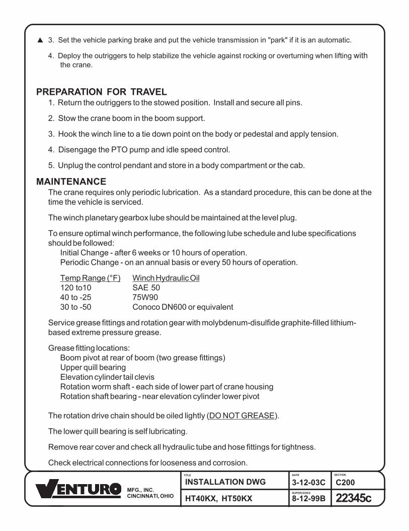
3. Set the vehicle parking brake and put the vehicle transmission in "park" if it is an automatic.
4. Deploy the outriggers to help stabilize the vehicle against rocking or overturning when lifting withthe crane.
PREPARATION FOR TRAVEL1. Return the outriggers to the stowed position. Install and secure all pins.
2. Stow the crane boom in the boom support.
3. Hook the winch line to a tie down point on the body or pedestal and apply tension.
4. Disengage the PTO pump and idle speed control.
5. Unplug the control pendant and store in a body compartment or the cab.
MAINTENANCEThe crane requires only periodic lubrication. As a standard procedure, this can be done at thetime the vehicle is serviced.
The winch planetary gearbox lube should be maintained at the level plug.
To ensure optimal winch performance, the following lube schedule and lube specificationsshould be followed:
Initial Change - after 6 weeks or 10 hours of operation.Periodic Change - on an annual basis or every 50 hours of operation.
Temp Range (°F) Winch Hydraulic Oil120 to10 SAE 5040 to -25 75W9030 to -50 Conoco DN600 or equivalent
Service grease fittings and rotation gear with molybdenum-disulfide graphite-filled lithium-based extreme pressure grease.
Grease fitting locations:Boom pivot at rear of boom (two grease fittings)Upper quill bearingElevation cylinder tail clevisRotation worm shaft - each side of lower part of crane housingRotation shaft bearing - near elevation cylinder lower pivot
The rotation drive chain should be oiled lightly (DO NOT GREASE).
The lower quill bearing is self lubricating.
Remove rear cover and check all hydraulic tube and hose fittings for tightness.
Check electrical connections for looseness and corrosion.

EXPLANATION OF HYDRAULIC VALVE SYSTEM
OVERVIEWVenturo’s hydraulic cranes are available in two general configurations: Proportional and Non-proportional. TheNon-proportional configuration utilizes a safety shutoff valve which, when not actuated, allows hydraulic fluid tobypass the valve bank and return to tank; the crane will not function when the safety shutoff valve is notactuated. When the safety shutoff valve is actuated (control pendant energizes the coil or the coil is manuallyoverridden), hydraulic fluid cycles through the valve bank and allows the crane to function. The Proportionalconfiguration utilizes a proportional valve which in its fully closed and fully opened positions functions similarly tothe safety shutoff valve, but adds the ability to operate the crane at any speed in between these two extremes.
In both the Non-proportional and Proportional configurations, the four crane functions (winch, rotation, boomelevation, and boom extension) are controlled by four separate valve sections. Each valve section has twosolenoid coils (and two manual overrides) which control the direction that the function operates (e.g. winch up vs.winch down). For a given crane function and direction (e.g. winch up) the solenoid coil and the associatedmanual override lie on the same side of the valve bank (both “push”).
22328C200
5-1-98A
9-24-03BHYDRAULIC SYSTEM
HT18, HT25, HT40/50SUPERCEDES
TITLE DATE SECTION
CINCINNATI, OHIOMFG., INC.
MANUAL OVERRIDE SYSTEMShould an electrical failure occur, your Venturo crane can be operated manually. The manual overrides areintended for emergency use only and should not be used for normal operation.
To operate in manual override mode:(1) Override the safety shutoff or proportional valve by turning the red stem on the valve as stated below.
Non-proportional system:For override operation, press stem in and rotate counterclockwise until it stops.To return to normal operation, press stem in and rotate clockwise until it stops.
Proportional system:For override operation, rotate stem clockwise (the farther the stem is turned the faster the crane will
operate).To return to normal operation, rotate the stem counterclockwise until it stops.
(2) Determine the coil/override associated with the function you wish to operate, then insert a small diameterobject (an allen wrench works well) into the detent on the end of the valve stem and press firmly inward. Forexample, pushing the stem labeled A on the first bank (refer to the illustration) will actuate winch down.
WARNING! For normal crane operation, the safety shutoff or proportional valve must be in the “normal” position(as described above). Test the crane before each use by placing the power toggle switch or trigger in the “OFF “position and testing each crane function using the manual overrides. If any crane function operates, verify thatthe red stem on the safety shutoff or proportional valve is in the normal position then retest.
EMERGENCY STOPIn the unlikely event that a function of the crane does not stop once the function’s toggle switch is released, theNon-proportional crane can be stopped by simply toggling the power switch to the off (emergency stop)position and the Proportional crane can be stopped by releasing the trigger.
System abbreviations are as follows:WD – Winch Down WU – Winch UpRR – Rotation Right RL – Rotation LeftBI – Boom In (Ext.) BO – Boom Out (Ext.)BD – Boom Down (Elev.) BU – Boom Up (Elev.)


2224
5C
200
4-19
-02C
11-2
2-02
DW
IRE
RO
PE IN
STA
LLA
TIO
N D
RA
WIN
G
ET/H
T25K
(X),H
T40K
X, H
T50K
XSU
PER
CED
ES
TITL
ED
ATE
SEC
TIO
N
CIN
CIN
NA
TI, O
HIO
MA
NU
FAC
TUR
ING
, IN
C.
STEP
1:
INSE
RT
WIR
E R
OPE
EN
D T
HR
OU
GH
ANTI
-TW
O-B
LOC
K W
EIG
HT.
STEP
2:
INSE
RT
WIR
E R
OPE
EN
D IN
TO P
OC
KET
OPE
NIN
G A
ND
TH
RO
UG
H W
EDG
EPO
CKE
T.
CAU
TIO
N:
IF T
HE
WIR
E R
OPE
IS N
OT
INST
ALLE
DFO
R T
HE
CO
RR
ECT
DR
UM
RO
TATI
ON
,TH
E W
INC
H B
RAK
E VA
LVE
WIL
L N
OT
HO
LD T
HE
LOAD
.
NO
TE:
ON
TH
E ET
25K(
X) A
7/1
6" H
EX N
UT
WIL
L BE
USE
D IN
LIE
U O
F A
WED
GE.
WIR
E R
OPE
INST
ALLA
TIO
N

SECTION 300
MAINTENANCE
&
SERVICE
7607300A

1454
4C
320
8-10
-98C
1-19
-00D
ASS
EMB
LY &
SER
VIC
E IN
ST.
ET 2
0,00
0, E
T20K
(X),
ET25
K(X
), H
T25K
(X),
HT4
0/50
KX
SUPE
RCED
ES
TITL
EDA
TESE
CTIO
N
CIN
CIN
NA
TI,
OH
IOM
AN
UFA
CTU
RIN
G,
INC
.

1455
3C
320
3-10
-82A
8-10
-98B
AS
SE
MB
LY &
SE
RV
ICE
INS
T.
ET
20,
000
CR
AN
ES
UP
ER
CE
DE
S
TIT
LED
AT
ES
EC
TIO
N
CIN
CIN
NA
TI,
OH
IOM
AN
UF
AC
TU
RIN
G, I
NC
.

SECTION 400
PARTS
7607400A


4126
404
WO
OD
RU
FF K
EY - 1
/4" x
1" (
MO
DIF
IED
)42
--
43-
-44
--
45-
-46
--
47-
-48
--
49-
-50
--
5122
494
FIEL
D S
ERVI
CE
LABE
L KIT
- HT4
0KX
NO
N-P
RO
P.52
2249
4-1
FIEL
D S
ERVI
CE
LABE
L KIT
- HT4
0KX
PRO
POR
TIO
NAL
5322
495
FIEL
D S
ERVI
CE
LABE
L KIT
- HT5
0KX
NO
N-P
RO
P.54
2249
5-1
FIEL
D S
ERVI
CE
LABE
L KIT
- HT5
0KX
PRO
POR
TIO
NAL
55-
-56
--
57-
-58
--
59-
-60
--
61-
-62
--
63-
-64
--
65-
-66
--
67-
-68
--
69-
-70
--
71-
-72
--
73-
-74
--
75-
-76
--
77-
-78
--
79-
-80
--
2251
7C
400
10-2
9-01
B
3-4-
03C
REP
LAC
EMEN
T PA
RTS
HT4
0KX,
HT5
0KX
SUPE
RC
EDES
TITL
ED
ATE
SEC
TIO
N
122
017
LOW
ER B
EAR
ING
- 8"
OD
x 1
.5" L
ON
G2
1408
4CO
UPLI
NG3
1414
2-4
WO
RM
- SIN
GLE
TH
REA
D R
H4
1415
9SH
IM -
1-1/
2" S
Q x
.015
", .0
42",
.105
"5
1419
1-1
BALL
TH
RU
ST B
EAR
ING
- 2"
ID x
3-1
1/32
" OD
614
191-
2BA
LL T
HR
UST
BEA
RIN
G -
1-1/
2" ID
x 2
-19/
32" O
D7
1424
2H
OU
SIN
G, W
OR
M G
EAR
814
245
WAS
HER
PLA
TE9
1434
1-1
BUSH
ING
- 2.
003"
ID x
2.2
52" O
D x
15/
16" L
ON
G10
1434
1-2
BUSH
ING
- 1.
503"
ID x
1.7
52" O
D x
1" L
ON
G11
1434
4SH
IM W
ASH
ER -
1-1/
2" ID
x 2
-1/8
" OD
x .0
05",
.015
", .0
31" T
HK
1222
468
HD
STE
EL F
LAN
GE
MO
UN
TED
BAL
L BE
ARIN
G - 1
" BO
RE
1314
384
SPR
OC
KET
AND
SH
AFT
ASSE
MBL
Y (4
0T S
PRO
CKE
T)14
1448
1R
OTA
TIO
N D
RIV
E C
HAI
N15
1524
5W
OO
DR
UFF
KEY
- 5/
16" x
1-1
/8" (
MO
DIF
IED
)16
1777
0H
EAD
ACH
E BA
LL A
SSEM
BLY
1718
068
BEAR
ING
HO
USI
NG
- 1-1
/8" L
ON
G18
1806
9FL
ANG
ED B
EAR
ING
- 2"
BO
RE
x 3" O
D F
LAN
GE
1922
006
WEL
DED
HO
USI
NG
ASS
EMBL
Y20
2202
1-1
ELEV
. CYL
. 4.5
" BO
RE
x 2"
RO
D x
19.
63" S
TRO
KE21
2202
2-1
ELEV
. CYL
. 5" B
OR
E x
2" R
OD
x 1
9.63
" STR
OKE
2222
024
STO
P R
ING
- RO
TATI
ON
2322
026
LOW
ER B
EAR
ING
PLA
TE A
SSEM
BLY
2422
030
QU
ILL
ASSE
MBL
Y25
2204
1W
OR
M G
EAR
- RO
TATI
ON
2624
524
BOO
M A
SSEM
BLY
- HT4
0/50
KX27
2455
0FU
LL P
OW
ER B
OO
M A
SSEM
BLY
- HT4
0/50
KXX
2822
266
WIN
CH
- 300
0 LB
(SIN
GLE
LIN
E) - H
T40K
X29
2226
8W
INC
H - 4
000
LB (S
ING
LE L
INE)
- HT5
0KX
3022
274
PIVO
T PI
N, C
YL T
AIL
- 1-1
/2" O
D x
2-1
3/16
" LO
NG
3122
275
PIVO
T PI
N, C
YL R
OD
- 1-
1/2"
OD
x 6
-7/8
" LO
NG
3222
290
PIVO
T PI
N, B
OO
M -
1-3/
4" O
D x
12-
1/2"
LO
NG
3322
291
SPR
OC
KET
AND
SH
AFT
ASSE
MBL
Y (1
0T S
PRO
CKE
T)34
2229
4H
YDR
AULI
C M
OTO
R - R
OTA
TIO
N35
2229
8LO
WER
CO
VER
3622
303
CH
AIN
CO
VER
3722
322
VALV
E C
OVE
R A
SSEM
BLY
3822
387
RAI
N C
OVE
R - Q
UIL
L39
--
4017
094-
3/8-
100
WIR
E R
OPE
ASS
EMBL
Y - 3
/8" x
100
FT
ITEM
#PA
RT
#D
ESC
RIP
TIO
NIT
EM #
PAR
T #
DES
CR
IPTI
ON
R
EPLA
CEM
ENT
PAR
TS D
WG
REF
223
46
CIN
CIN
NA
TI, O
HIO
MA
NU
FAC
TUR
ING
, IN
C.
1IT
EM N
OT
SHO
WN
ON
REP
LAC
EMEN
T PA
RTS
DR
AWIN
G
1 1

22518C400
6-8-98A
7-17-00BREPL. FASTENERS LIST
HT40KX, HT50KXSUPERCEDES
TITLE DATE SECTION
14353 COIL PIN - 1/2" x 1-1/2" 10 BASE PLATE!HHCS05013150 HHCS - 1/2"-13 x 1-1/2" 10 BASE PLATE!LWSH-050 LOCK WASHER - 1/2" 10 BASE PLATE18927 CAP SCREW - MODIFIED 12 BULL GEAR!LWSH-050-HC LOCK WASHER - 1/2" HI COLLAR 12 BULL GEAR!HHCS06311175 HHCS - 5/8"-11 x 1-3/4" 4 WORM HOUSING!LWSH-063 LOCK WASHER - 5/8" 4 WORM HOUSING!SHCS05020125 SHCS - 1/2"-20 x 1-1/4" 2 WORM HOUSING25593 SET SCREW - FLAT FACE 1/2"-20 x 1" 5 WORM HOUSING!HHCS02520063-5 HHCS 1/4"-20 x 5/8" 7 LOWER CHAIN COVER!LWSH-025 LOCK WASHER - 1/4" 7 LOWER CHAIN COVER!UNUT15195-1420 FASTENER, U-NUT, 1/4"-20 7 LOWER CHAIN COVER!HHCS02520063-5 HHCS 1/4"-20 x 5/8" 2 SIDE CHAIN COVER!HHCS02520375 HHCS - 1/4"-20 x 3-3/4" 1 SIDE CHAIN COVER!HNUT-02520 HEX NUT - 1/4"-20 1 SIDE CHAIN COVER!LWSH-025 LOCK WASHER - 1/4" 3 SIDE CHAIN COVER!HHCS02520063-5 HHCS - 1/4"-20 x 5/8" 4 VALVE BACK COVER!LWSH-025 LOCK WASHER - 1/4" 4 VALVE BACK COVER!SHCS03816350 SHCS - 3/8"-16 x 3-1/2" 2 VALVE BANK!HNUT-03816 HEX NUT - 3/8"-16 2 VALVE BANK!LWSH-038-HC LOCK WASHER - 3/8" HI COLLAR 2 VALVE BANK12534-4 BUSHING - 1/2" I.D. x 7/8" O.D. x 14 GA 4 VALVE BANK!RPIN-025200 ROLL PIN - 1/4" DIA x 2" LONG 4 ELEVATION CYLINDER PINS!HHCS03816125 HHCS - 3/8"-16 x 1-1/4" 2 ROTATION SHAFT BEARING!HWSH-038SAE HEX WASHER - SAE 3/8" 2 ROTATION SHAFT BEARING!LWSH-038 LOCK WASHER - 3/8" 2 ROTATION SHAFT BEARING!HNUT-03816 HEX NUT - 3/8"-16 2 ROTATION SHAFT BEARING!HHCS03118100-5 HHCS - 5/16"-18 x 1-1/2" 1 SUPPORT-ROTATION BEARING!HNUT-03118 HEX NUT - 5/16"-18 1 SUPPORT-ROTATION BEARING!HHCS05013175 HHCS - 1/2"-13 x 1-3/4" 2 ROTATION MOTOR!LWSH-050-STAR LOCK WASHER - 1/2" STAR 2 ROTATION MOTOR!LWSH-050 LOCK WASHER - 1/2" 2 ROTATION MOTOR!HNUT-05013 HEX NUT - 1/2"-13 2 ROTATION MOTOR!HHCS05013225 HHCS - 1/2"-13 x 2-1/4" 4 WINCH!LWSH-050 LOCK WASHER - 1/2" 4 WINCH!FWSH-050 FLAT WASHER - 1/2" 4 WINCH!HNUT-05013 HEX NUT - 1/2"-13 4 WINCH19269 CLAMP, CABLE - 1/4" 1 PRESSURE SWITCH HARNESS!HHCS02520063-5 HHCS - 1/4"-20 x 5/8" 1 PRESSURE SWITCH HARNESS!LWSH-025 LOCK WASHER - 1/4" 1 PRESSURE SWITCH HARNESS!HHCS05013125-5 HHCS - 1/2"-13 x 1-1/4" 4 UPPER BEARING!LWSH-050 LOCK WASHER - 1/2" 4 UPPER BEARING!HHCS03816100 HHCS - 3/8"-16 x 1" 4 WINCH (BACK SIDE)!FWSH-038 FLAT WASHER - 3/8" 4 WINCH (BACK SIDE)!LWSH-038 LOCK WASHER - 3/8" 4 WINCH (BACK SIDE)19271-2 PLASTIC PLUG - 2-1/8" DIA 2 WINCH ACCESS HOLES!HHCS05013300 HHCS - 1/2"-13 x 3" 1 BOOM PIVOT PINRL-644 INSULATING PLUG - 1" 4 LOWER HOUSING!LNUT-05013 LOCK NUT - 1/2"-13 NYLON INSERT 1 BOOM PIVOT PIN!HHCS02520075-5 HHCS - 1/4"-20 x 3/4" 1 GROUND SCREW!PHCS#1024050 PHCS - #10-24 x 1/2" 2 CIRCUIT BREAKER!LWSH-#10 LOCK WASHER - #10 2 CIRCUIT BREAKER!PHCS#0632100 PHCS - 6-32 x 1" 2 TERMINAL BLOCK!PHCS03816050 PHCS - 3/8"-16 x 1/2" 1 COUPLING FOR MASTER BYPASS VALVE- - - -
PART NUMBER DESCRIPTION QTY LOCATION/FUNCTION
FASTENER LIST FOR HT40/50KX
CINCINNATI, OHIOMFG., INC.
REPLACEMENT PARTS DWG REF 22346
SERIAL NO. 84030 & UPSERIAL NO. 85030 & UP

DATE
SECT
ION
SUPE
RSED
ES
TITL
E
MA
NU
FA
CT
UR
ING
, IN
C.
CIN
CIN
NA
TI, O
HIO
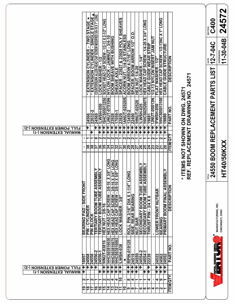
2457
124
550
BOO
M P
ARTS
DRA
WIN
G
HT40
/50K
XX
3-4-
03
-
C400
2455
0 BO
OM P
ARTS
DRA
WIN
G
AB
B
24
25 26 27
212223
41211
141115
282930
A
SECT
ION B
-B
CC
1
2
10
35
36
SECT
ION A
-ARE
F. R
EPLA
CEM
ENT
PART
S LI
ST 2
4572
6
59
3 11 13
6
16
3
3
313234
33
1
6
2
SECT
ION C
-C
12 10 32
4
419
2

HT40
HT50
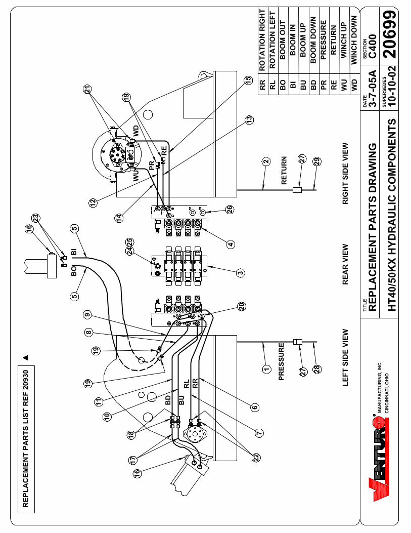
HYDRAULIC SYSTEM COMPONENTS - HT40/50KX CRANESREPLACEMENT PARTS LIST
ITEM PART NUMBER DESCRIPTION
1 20685 PRESSURE HOSE - HOUSING SIDE2 20686 RETURN HOSE - HOUSING SIDE3 22501 VALVE BANK - HT40KX, HT50KX4 22523 VALVE ASSEMBLY (VALVE BLOCK, VALVE, COIL, & HARDWARE)
22362 COIL ONLY5 22363 EXTENSION CYLINDER HOSE
6 22505 HYD TUBING - ROTATION RIGHT7 22506 HYD TUBING - ROTATION LEFT8 22507 HYD TUBING - BOOM OUT9 22508 HYD TUBING - BOOM IN10 22509 HYD TUBING - BOOM UP
11 22510 HYD TUBING - BOOM DOWN12 22511 HYD TUBING - PRESSURE13 22512 HYD TUBING - RETURN14 22513 HYD TUBING - WINCH UP15 22514 HYD TUBING - WINCH DOWN
16 19247 COUNTERBALANCE VALVE (ELEVATION & EXTENSION CYLINDERS)17 22382 ELEV CYLINDER HOSE - 22" x 6MBX x 6FJX18 HBLK6MJ-6MJ HYD BULKHEAD19 HBLK6MJ-6MJ-90 HYD BULKHEAD UNION ELBOW WITH LOCK NUT - 6MJ x 90°20 HNPL6MJ-6MO HYD NIPPLE
21 HELB8MO-6MJ-90 HYD ELBOW22 HNPL10MO-6MJ HYD NIPPLE23 HRDB6MO-4FP HYDRAULIC BUSHING - 6MO-4FP24 22502 PROPORTIONAL VALVE25 22503 MASTER BYPASS VALVE AND COIL
26 22312-X.XX PRIORITY FLOW CART (X.XX REFER TO CHART BELOW)27 20684 LIVE CONTINUOUS HYDRAULIC SWIVEL28 20687 PRESSURE HOSE - COMPARTMENT SIDE30 20688 RETURN HOSE - COMPARTMENT SIDE
TITLE SECTION
SUPERCEDES
DATE
20930C400
-
10-10-02REPL. PARTS LIST
HT40/50KXCINCINNATI, OHIOMFG., INC.
REPLACEMENT PARTS DWG REF 20699
SERIAL NO. 84030 & UPSERIAL NO. 85030 & UP
STANDARD PROPORTIONAL(NON-PROP)
EXTENSION 1.25 2.25
ELEVATION 1.75 4.00
EXTENSION 1.25 2.25
ELEVATION 2.25 4.00

C400
REP
LAC
EMEN
T PA
RTS
DR
AW
ING
2206
2 PE
ND
AN
T (S
TAN
DA
RD
CTR
L)-7-
8-04
DA
TESE
CTI
ON
SUPE
RSED
ES
TITL
E
2207
8M
AN
UFA
CTU
RIN
G, I
NC
.C
INC
INN
ATI
, OH
IO
2206
2 PE
ND
AN
T(S
TAN
DA
RD
CTR
L)
PLU
G -
BA
CK
SID
E VI
EW
YELL
OW
/ B
LAC
K -
WD
RED
/ B
LAC
K -
RR
GR
EEN
/ B
LAC
K -
BD
ORA
NGE
& O
RG/B
LK -
12V+
YELL
OW
- W
UR
ED -
RL
GR
EEN
- B
U
BLA
CK
- M
AST
ER B
YPA
SS V
ALV
E
PART
NO
.1
4IT
EMQ
TY22
081
31
21
1942
619
427
DES
CR
IPTI
ON
MA
LE IN
SER
T - 1
0 +
1 PO
LEPL
UG
CA
SE -
10 +
1 P
OLE
SPD
T M
OM
ENTA
RY
SWIT
CH
3
32
1BL
UE /
BLAC
K - B
IBL
UE -
BO

C40
0SE
CTIO
NTI
TLE
DES
CR
IPTI
ON
WEI
GH
T A
SSY.
M
ICR
OSW
ITC
H
HH
CS
1/4-
20 x
2-3
/4"
GR
. 5FL
AT
WA
SHER
1/4
LOC
K N
UT,
NYL
ON
1/4
-20
CO
NN
ECTO
R /
SET-
CO
LLA
R A
SSEM
BLY
LOC
KN
UT
(1/2
" PI
PE)
STR
AIN
REL
IEF
- 90D
EGST
RA
IN R
ELIE
F - S
TRA
IGH
T (1
/2"
PIPE
)C
AB
LE G
UID
E - B
LAC
K D
ELR
IN
PART
NO
.Q
TYIT
EM
1 1 1 1 1 1 1 112345678910
6 122
453
2245
622
454
2245
519
060
PL-2
0-46
9
!FW
SH-0
25!L
NU
T-02
520
111112
1937
7-3
MA
NU
FAC
TUR
ING
, IN
C.
CIN
CIN
NA
TI, O
HIO
DA
TE
SUPE
RSE
DES
2268
3
2268
4
26
7
5
DET
AIL
VIE
W -
A
!HH
CS0
2520
275
98
43
10A
1
2095
1-3
HA
NG
ER C
AB
LEC
OR
D R
EEL
ASS
EMB
LY -
LEFT
HA
ND
NO
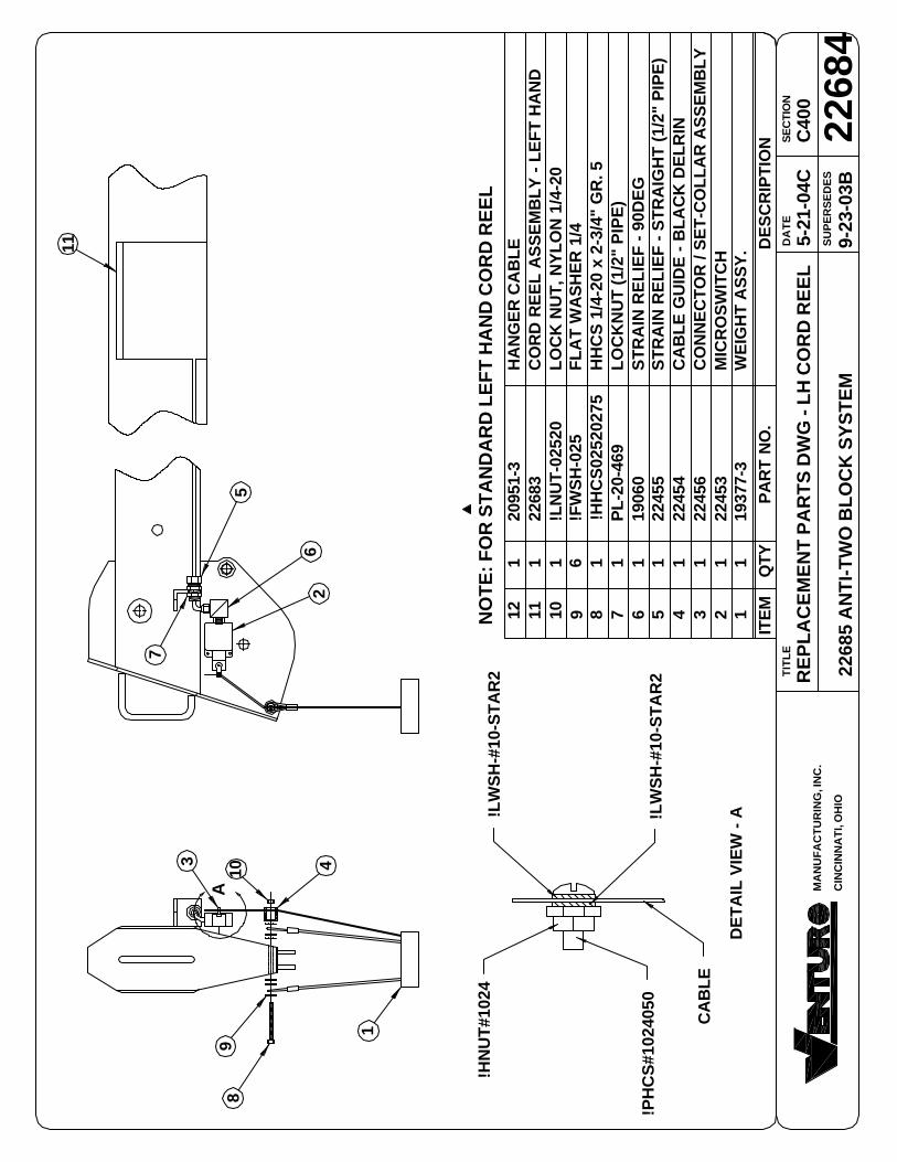
TE: F
OR
STA
ND
AR
D L
EFT
HA
ND
CO
RD
REE
L
11
REP
LAC
EMEN
T PA
RTS
DW
G -
LH C
OR
D R
EEL
2268
5 A
NTI
-TW
O B
LOC
K S
YSTE
M9-
23-0
3B
5-21
-04C
!LW
SH-#
10-S
TAR
2
CA
BLE
!HN
UT#
1024
!LW
SH-#
10-S
TAR
2
!PH
CS#
1024
050

DET
AIL
VIE
W -
A
HT4
0KX,
HT5
0KX
C40
0
2244
9SE
CTIO
NTI
TLE
DES
CR
IPTI
ON
WEI
GH
T A
SSY.
M
ICR
OSW
ITC
H
HH
CS
1/4-
20 x
2-3
/4"
GR
. 5FL
AT
WA
SHER
1/4
LOC
K N
UT,
NYL
ON
1/4
-20
CO
VER
- C
OR
D R
EEL
CO
NN
ECTO
R /
SET-
CO
LLA
R A
SSEM
BLY
LOC
KN
UT
(1/2
" PI
PE)
STR
AIN
REL
IEF
- 90D
EGST
RA
IN R
ELIE
F - S
TRA
IGH
T (1
/2"
PIPE
)C
AB
LE G
UID
E - B
LAC
K D
ELR
IN
HA
NG
ER C
AB
LE
PART
NO
.Q
TYIT
EM
1 1 1 1 1 1 1 112345678910
6 122
453
2245
622
454
2245
519
060
PL-2
0-46
9
!FW
SH-0
25!L
NU
T-02
520
1111
1905
812
1937
7-3
1320
951-
32
2238
8
!HH
CS0
2520
275-
5
MA
NU
FAC
TUR
ING
, IN
C.
CIN
CIN
NA
TI, O
HIO
DA
TE
SUPE
RSE
DES
13
98
1
43 10
26
7
12
5
11
A
NO
TE: F
OR
OPT
ION
AL
RIG
HT
HA
ND
CO
RD
REE
L.
CO
RD
REE
L A
SSEM
BLY
- R
H
7-3-
03C
5-21
-04D
!LW
SH-#
10-S
TAR
2
CA
BLE
!HN
UT#
1024
!LW
SH-#
10-S
TAR
2
!PH
CS#
1024
050


LIMITED WARRANTY POLICY
This limited policy warrants new products of Venturo be free from defects in material and workmanshipfor a period of one (1) year from date of original installation. This warranty covers:
♦ Repair or replacement of product♦♦♦♦♦ Labor to repair or replace product♦♦♦♦♦ Freight to return and/or replace product
We shall not be liable for any contingent liabilities arising out of the improper function of any products.Warranty shall become void if the product is improperly installed, modified, damaged, abused or usedfor application other than intended use.
WARRANTY CLAIMS
Venturo Manufacturing, Inc. will make a good faith effort for prompt correction or other adjustment withrespect to any product, which proves to be defective after our inspection and within the warranty period.Before any repairs are attempted or before returning any product, your Venturo Distributor is required toobtain a warranty claim number. This number is necessary for any claim to be considered. To obtain awarranty claim number, Venturo requires the model and serial number. Only authorized Venturo Dis-tributors can perform warranty. For the name and address of your local Venturo Distributor call theWarranty Claim Department – 513-772-8448.
WARNING – It is the responsibility of the installer to insure the installation is completed according to themanufacturer’s recommendations, insure the ultimate user understands how to operate product in asafe manner and understands the need for regular service and maintenance by an authorized VenturoDistributor. No modifications or alterations may be made to any Venturo products without the ex-pressed written consent of the manufacturer. Reinstallation of any Venturo product must be done by anauthorized Venturo Distributor, to the standards of the industry including maintenance, service andaffixing of all instruction, safety and warning decals. Users should again be instructed as to the safeoperation at time of delivery. Maintenance, service, operation and safety warning decals are availableon request from Venturo Manufacturing, Inc.
12-00073A
VENTURO MANUFACTURING, INCDIVISION OF COLLINS ASSOCIATES, INC
12110 BEST PLACE CINCINNATI, OHIO 45241513.772.8448
www.venturo.com
•