Embed Size (px)
Citation preview


SECTIONDATE
SUPERSEDES
TITLE
VC620 W/ UNIV. S/F
-08-01-17E
01-13-16D
TABLE OF CONTENTS
620630VENCO VENTURO INDUSTRIES LLC
CINCINNATI, OHIO
®
TABLE OF CONTENTSVC620 W/ UNIVERSAL SUB-FRAME; OWNER'S MANUAL
SECTION 200 INSTALLATION520951 INSTALLATION WARNINGS416733 CAUTIONARY NOTICE620103 CAPACITY CHART, VC620620104 CAPACITY CHART, VC620 (SUB-FRAME)620122 MOUNTING DIMENSIONS520938 UNIVERSAL SUB-FRAME FEATURES416086 IMPORTANT WARNING520604 HOIST MOUNTING INSTRUCTIONS520605 HOIST MOUNTING INSTRUCTIONS520609 HOIST MOUNTING INSTRUCTIONS520093 INSTALLATION INSTRUCTIONS662861 HINGE TO BED MOUNTING INSTRUCTIONS520941 HOIST MOUNTING INSTRUCTIONS, UNIVERSAL SUB-FRAME552009 SHEAR PLATE LOCATION520608 MOUNTING ILLUSTRATION620246 CABLE / HANDLE ASSEMBLY416755 PTO PUMP CABLE INSTALLATION416763 SPLIT PUMP520621 SPDG HOSE CONNECTION DIAGRAM416287 WILLIAMS PTO WARNING416640 HYDRAULIC POWER UNIT GROUND CABLE INSTALLATION6368 HYDRAULIC POWER UNIT GROUNDING416809 40058M / MHD POWER UNIT416307 416081M ED POWER UNIT416140 FILLING HYDRAULIC RESERVOIR416128 DECAL LOCATIONS
SECTION 250 OPERATIONS520952 OPERATOR WARNINGS520079 MAINTENANCE & OPERATION INSTRUCTIONS416644 BODY PROP OPERATION GUIDE, GENERAL416645 BODY PROP OPERATION GUIDE, ILLUSTRATIONS / INSTRUCTIONS
SECTION 300 MAINTENANCE520054 HOISTS GREASE POINTS
SECTION 400 REPLACEMENT PARTS628820 DECAL LIST620119 REPLACEMENT PARTS DWG, VC620 HOIST620120 REPLACEMENT PARTS LIST, VC620 HOIST620133 REPLACEMENT PARTS DWG, VC620 HOIST W/ LINKAGE PROP620134 REPLACEMENT PARTS LIST, VC620 HOIST W/ LINKAGE PROP620117 REPLACEMENT PARTS DWG, VC620 PIVOTS620118 REPLACEMENT PARTS LIST, VC620 PIVOTS520939 REPLACEMENT PARTS DWG, VC416-620 UNIVERSAL SUB-FRAME520940 REPLACEMENT PARTS LIST, VC416-620 UNIVERSAL SUB-FRAME416308 REPLACEMENT PARTS DIAGRAM, 40058M /MHD POWER UNITS416508 REPLACEMENT PARTS DIAGRAM, 416081M POWER UNITS620245 REPLACEMENT PARTS DIAGRAM, PTO PUMP CABLE/CONCOLE
USER NOTES (1)USER NOTES (2)WARRANTY POLICY

516913
VENCO VENTURO INDUSTRIES LLC
CINCINNATI, OHIO
®

SECTIONDATE
SUPERSEDES
TITLE
HOISTS
-12-02-15A
09-03-15
INSTALLATION WARNING
520951VENCO VENTURO INDUSTRIES LLC
CINCINNATI, OHIO
®
READ THIS FIRSTINSTALLATION WARNINGS
► Read and fully understand entire owner's manual prior to installation.
► Refer to Body Builder's Guide BEFORE welding or drilling on chassis as not to void the chassis warranty.
► When drilling the chassis make sure all brake lines, wire harnesses, and hoses are protected so as not to causedamage to these items resulting in failure. All fasteners must be installed so they do not interfere with these items aswell.
► Cover all fuel related items (hoses, brake lines, wiring, etc.) so as not to cause fire or explosions that will result inserious injury or death.
► Route all wiring and hoses away from exhaust systems. Heat from exhaust systems can cause melting of wiring andhoses, resulting in fire and/or explosions that could result in serious injury or death.
► Only use body prop when vehicle is on firm level ground, and with an UNLOADED body only!
► NEVER work under a raised body without the use of the body prop. Failure to do so can cause serious injury ordeath.
► Hydraulic system must be designed to work within the manufacturer's specifications. Systems with more flow or PSIcan cause hoist to fail during the dumping of a load; which could cause damage, serious injury or death.
► NEVER adjust factory relief valve settings without consulting with the factory.
► Fluid under pressure can pierce the skin and enter the bloodstream, causing serious injury or death. Always weareye protection and protective clothing when working around hydraulic systems.
► NEVER operate hoist from outside the cab. Doing so can cause serious injury or death.
► NEVER perform maintenance on a Hoist without applying the following:►► Chassis brake set and engine turned off►► Removing battery cable, if necessary►► Properly deploying the Hoist body prop
► Venco hoists are designed for and intended to be used on stationary trucks dumping on firm and level ground.Spreading applications and/or shock unloading are strictly prohibited and will void this warranty.
SECTIONDATE
SUPERSEDES
TITLE
HOISTS
-12-07-15D
11-04-15C
CAUTIONARY NOTICE
416733VENCO VENTURO INDUSTRIES LLC
CINCINNATI, OHIO
®
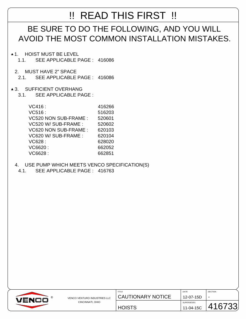
!! READ THIS FIRST !!BE SURE TO DO THE FOLLOWING, AND YOU WILL
AVOID THE MOST COMMON INSTALLATION MISTAKES.
1. HOIST MUST BE LEVEL1.1. SEE APPLICABLE PAGE : 416086
2. MUST HAVE 2" SPACE2.1. SEE APPLICABLE PAGE : 416086
3. SUFFICIENT OVERHANG3.1. SEE APPLICABLE PAGE :
VC416 : 416266VC516 : 516203VC520 NON SUB-FRAME : 520601VC520 W/ SUB-FRAME : 520602VC620 NON SUB-FRAME : 620103VC620 W/ SUB-FRAME : 620104VC628 : 628020VC6620 : 662052VC6628 : 662851
4. USE PUMP WHICH MEETS VENCO SPECIFICATION(S)4.1. SEE APPLICABLE PAGE : 416763

CAPACITIES ARE BASED ON WATER LEVELS AND NON-DIMINISHING LOADS. DUE TO THE VARIATIONS IN TRUCKEQUIPMENT AND CAB-AXLE LENGTHS (CA), THE DATA PROVIDED ON THIS PAGE IS TO BE USED AS A GUIDELINEONLY .
SECTIONDATE
SUPERSEDES
TITLE
VC 620 HOIST
H20011-06-15D
01-22-15C
CAPACITY CHART
620103VENCO VENTURO INDUSTRIES LLC
CINCINNATI, OHIO
®
VENCO HOIST MODEL VC620
DUMP CLASS: 40 CONVERSION CLASS: D WEIGHT: 595 LBS.
POWER SOURCE: ADDITIONAL DATA:ES - ELECTRIC SINGLE ACTING 6" BORE x 20" STROKEED - ELECTRIC DOUBLE ACTING CA: 84" - 138"PD - POWER TAKE OFF DOUBLE ACTING DUMP ANGLE: 40° - 50°
MOUNTING HEIGHT REQ'D: 8"
* VENCO hoists are designed for and intended to be used on stationary trucks dumping on firm and level ground. Spreadingapplications and/or shock unloading are strictly prohibited and will void this warranty.
BODY CA OH 40° (TON) 45° (TON) 50°(TON)
13' 84" 42" 24.0 21.4 19.4
13' 102" 24" 16.0 14.3 12.9
13' 108" 18" 14.4 12.9 11.6
13' 114" 12" 13.1 11.7 10.6
13' 120" 6" 12.0 10.7 9.7
14' 102" 36" 18.0 16.1 14.5
14' 108" 30" 16.0 14.3 12.9
14' 114" 24" 14.4 12.9 11.6
14' 120" 18" 13.1 11.7 10.6
14' 124" 14" 12.4 11.0 10.0
14' 126" 12" 12.0 10.7 9.7
15' 102" 48" 20.6 18.4 16.6
15' 108" 42" 18.0 16.1 14.5
15' 114" 36" 16.0 14.3 12.9
15' 120" 30" 14.4 12.9 11.6
15' 124" 26" 13.5 12.0 10.9
15' 126" 24" 13.1 11.7 10.6
15' 138" 12" 11.1 9.9 8.9
16' 114" 48" 18.0 16.1 14.5
16' 120" 42" 16.0 14.3 12.9
16' 124" 38" 14.9 13.3 12.0
16' 126" 36" 14.4 12.9 11.6
16' 138" 25" 12.0 10.7 9.7
16' 144" 18" 11.1 9.9 8.9
CONVERSION APPLICATIONS VC620
BODY CA O.H. 40° (TON) 45° (TON) 50°(TON)
8' - 12" 24.0 21.4 19.4
9' - 12" 20.6 18.4 16.6
10' - 12" 18.0 16.1 14.5
12' - 12" 14.4 12.9 11.6
DUMP BODY APPLICATIONS VC620 *

CAPACITIES ARE BASED ON WATER LEVELS AND NON-DIMINISHING LOADS. DUE TO THE VARIATIONS IN TRUCKEQUIPMENT AND CAB-AXLE LENGTHS (CA), THE DATA PROVIDED ON THIS PAGE IS TO BE USED AS A GUIDELINEONLY .
SECTIONDATE
SUPERSEDES
TITLE
VC 620 HOIST W/ SF
H20011-06-15E
01-22-15D
CAPACITY CHART
620104VENCO VENTURO INDUSTRIES LLC
CINCINNATI, OHIO
®
VENCO HOIST MODEL VC620 W/ SUBFRAME
DUMP CLASS: 40 CONVERSION CLASS: D WEIGHT: 825 LBS.
POWER SOURCE: ADDITIONAL DATA:ES - ELECTRIC SINGLE ACTING 6" BORE x 20" STROKEED - ELECTRIC DOUBLE ACTING CA: 84" - 138"PD - POWER TAKE OFF DOUBLE ACTING DUMP ANGLE: 45° - 50°
MOUNTING HEIGHT REQ'D: 6-7/8"
* VENCO hoists are designed for and intended to be used on stationary trucks dumping on firm and level ground. Spreadingapplications and/or shock unloading are strictly prohibited and will void this warranty.
BODY CA OH 45° (TON) 50°(TON)
13' 84" 42" 21.8 19.7
13' 102" 24" 14.5 13.1
13' 108" 18" 13.1 11.8
13' 114" 12" 11.9 10.7
13' 120" 6" 10.9 9.9
14' 102" 36" 16.3 14.8
14' 108" 30" 14.5 13.1
14' 114" 24" 13.1 11.8
14' 120" 18" 11.9 10.7
14' 124" 14" 11.2 10.1
14' 126" 12" 10.9 9.9
15' 102" 48" 18.7 16.9
15' 108" 42" 16.3 14.8
15' 114" 36" 14.5 13.1
15' 120" 30" 13.1 11.8
15' 124" 26" 12.2 11.1
15' 126" 24" 11.9 10.7
15' 138" 12" 10.0 9.1
16' 114" 48" 16.3 14.8
16' 120" 42" 14.5 13.1
16' 124" 38" 13.5 12.2
16' 126" 36" 13.1 11.8
16' 138" 25" 10.9 9.9
16' 144" 18" 10.0 9.1
CONVERSION APPLICATIONS VC620 W/ SUBFRAME
BODY CA O.H. 45° (TON) 50°(TON)
8' - 12" 21.8 19.7
9' - 12" 18.7 16.9
10' - 12" 16.3 14.8
12' - 12" 13.1 11.8
DUMP BODY APPLICATIONS VC620 W/ SUBFRAME *

VE
NC
OV
EN
TU
RO
IND
US
TR
IES
LLC
CIN
CIN
NA
TI,
OH
IO
H20
0M
OU
NT
ING
DIM
EN
SIO
NS
VC
620
HO
IST
(NO
N-S
UB
FR
AM
E)
11-0
9-15
BD
AT
ES
EC
TIO
N
SU
PE
RS
ED
ES
TIT
LE
6201
2206
-18-
03
®
VC
620
HO
IST
(NO
N-S
UB
FR
AM
E)
FIG
UR
E1.
A
DU
MP
AN
GLE
M
40°
45°
50°
102"
91"
83"
ST
AN
DA
RD
/RE
VE
RS
EM
OU
NT
ING
RE
VE
RS
EM
OU
NT
ING
CE
NT
ER
LIN
EO
FB
OT
TO
MP
IVO
T
HIN
GE
SH
AF
T
ST
AN
DA
RD
MO
UN
TIN
G
BE
D
WB
CA
38"
MA
X
MO
H

10
7.3
8(F
ITS
60
"C
AW
ITH
OU
TS
FE
XT
EN
SIO
NS
)
85
.47
(VC
52
0/6
20,
50
ºD
UM
PA
NG
LE
)
90
.29
(VC
52
0/6
20,
45
ºD
UM
PA
NG
LE
)
RO
CK
ER
ST
YLE
RE
AR
HIN
GE
S-
AC
CO
MM
OD
AT
ES
ALL
TY
PE
SO
FB
OD
YR
AIL
SIN
CL
UD
ING
TR
AP
EZ
OID
AL
&'C
'-C
HA
NN
EL.
20
12
+F
OR
DS
UP
ER
DU
TY
RE
AR
SH
EA
RP
LA
TE
W/M
AT
CH
ING
CH
AS
SIS
HO
LE
/BO
LT
PA
TT
ER
N.
UR
EA
FIL
LE
RK
NO
CK
-OU
TF
OR
MID
UR
EA
TA
NK
INS
TA
LLA
TIO
NS
.
AD
AP
TA
BLE
BO
DY
GU
IDE
;A
CC
OM
MO
DA
TE
ST
RA
PE
ZO
IDA
LA
ND
'C'C
HA
NN
EL
BO
DY
RA
ILS
.P
OS
ITIO
N&
WE
LD
AC
CO
RD
ING
LY
.S
EE
DR
AW
ING
52
09
39
FO
RM
OR
ED
ET
AIL
S.
HY
DR
AU
LIC
PO
WE
RU
NIT
MO
UN
TIN
GL
OC
AT
ION
S
JO
INE
DT
OS
F
(34
.00)
AA
SE
CT
ION
A-A
EN
DV
IEW
71
.00
(VC
41
6/5
16,
50
ºD
UM
PA
NG
LE
)
78
.00
(VC
41
5/5
16,
45
ºD
UM
PA
NG
LE
)
CR
OS
SM
EM
BE
RP
OS
ITIO
NIN
G
SE
CT
ION
A-A
CR
OS
SM
EM
BE
R
LO
CA
TIO
NF
OR
ED
PO
WE
RU
NIT
S
LO
CA
TIO
NF
OR
ES
PO
WE
RU
NIT
S
MO
UN
TIN
GP
RO
VIS
ION
SO
NS
UB
FR
AM
EE
XT
EN
SIO
NS
NO
TE
:T
HE
SC
ISS
OR
SS
UP
PO
RT
CR
OS
SM
EM
BE
RC
AN
BE
PO
SIT
ION
ED
TO
SU
PP
OR
TV
C41
6T
HR
UV
C620
MO
DE
LH
OIS
TS
.N
OT
E:
TH
ISS
UP
PO
RT
KE
EP
ST
HE
HO
IST
'LE
VE
L'
FO
RO
PT
IMU
MP
ER
FO
RM
AN
CE
AN
DR
ED
UC
ED
WE
AR
.
NO
TE
:T
HE
CR
OS
SM
EM
BE
R/H
YD
RA
UL
ICP
OW
ER
UN
ITM
OU
NT
ING
BR
AC
KE
TA
CC
OM
MO
DA
TE
SE
S&
ED
PO
WE
RU
NIT
S.
TH
EC
RO
SS
ME
MB
ER
IS'F
AC
TO
RY
INS
TA
LL
ED
'O
NT
HE
MA
INS
UB
FR
AM
EA
SS
HO
WN
BE
LO
WA
ND
ISS
ET
UP
FO
RA
N'
ED
'H
YD
RA
UL
ICP
OW
ER
UN
IT.
IFS
UB
FR
AM
EE
XT
EN
SIO
NS
AR
EU
SE
D,Y
OU
CA
NM
OU
NT
TH
EP
OW
ER
UN
ITT
OT
HE
EX
TE
NS
ION
SA
SS
HO
WN
.
NO
TE
:F
OR
ES
PO
WE
RU
NIT
SY
OU
MU
ST
RE
LO
CA
TE
TH
EC
RO
SS
ME
MB
ER
TO
TH
EE
SM
OU
NT
ING
SLO
TP
OS
ITIO
NA
SS
HO
WN
BE
LO
WO
RS
WA
PE
ND
SO
FT
HE
CR
OS
SM
EM
BE
RT
OS
UIT
.
VC
416/5
16
VC
520/6
20
SH
IMS
FO
RS
UB
FR
AM
EE
XT
EN
ION
SS
HIP
PE
DL
OO
SE
;IN
ST
AL
LE
RT
OW
ELD
SH
IMS
ON
TO
SF
EX
TE
NS
ION
SA
SR
EQ
.-JO
INT
OS
F-
GR
OU
ND
HY
DP
WR
UN
ITT
OT
RU
CK
FR
AM
EW
ITH
GR
OU
ND
ST
RA
PK
ITP
/N6474-
JOIN
TO
SF
-
SF
EX
TE
NS
ION
JO
INE
RP
LA
TE
VE
NC
OV
EN
TU
RO
IND
US
TR
IES
LLC
CIN
CIN
NA
TI,
OH
IO
-U
NIV
ER
SA
LS
UB
-FR
AM
EF
EA
TU
RE
S
VC
41
6-
VC
62
0H
OIS
TS
07
-07
-17J
DA
TE
SE
CT
ION
SU
PE
RS
ED
ES
TIT
LE
52
0938
04
-27
-16H
®
ST
AN
DA
RD
SU
PP
OR
TA
LT
ER
NA
TE
OR
IEN
TA
TIO
N(O
nly
wh
en
req
uir
ed
for
gre
ate
rc
leara
nce)
CA
UT
ION
!V
C4
16
,V
C5
16
,&
VC
52
0O
NL
Y
The
altern
ate
orien
tatio
nsho
wn
above
must
be
use
dif
any
port
ion
of
the
hois
to
pe
ratio
nin
terf
ere
sw
ithth
eveh
icle
'sstr
uctu
rea
nd
/or
com
ponents
.

SECTIONDATE
SUPERSEDES
TITLE
VENCO HOISTS
H20011-05-15N
08-10-15M
IMPORTANT WARNING
416086VENCO VENTURO INDUSTRIES LLC
CINCINNATI, OHIO
®
VC416 / VC516
VC6628
VC5520 / VC6620
VC628
VC520 / VC620 (620200)
Mounted Level(VC416 shown)
Level
Level top edge
Level
Level
Level
2" MIN
When installing the hoist, be sure to keep the hoist on a horizontal plane - LEVEL - withthe truck frame.
!! IMPORTANT !!A minimum clearance of 2" is required between the hoist (upper arm) and the body cross-members in order to prevent a mechanical lockout. If clearance is less than 2", then cross-members must be notched above arms.
!! IMPORTANT WARNING !!* ALL VENCO CONVERSION HOISTS → VC416 THRU VC6628 *
NOTCH CROSS-MEMBERS
!! IMPORTANT !!THE HOIST SCISSOR MUST BE SUPPORTED WITH A CHASSIS-MOUNTED SUPPORT CROSSMEMBER.IF THE TRUCK CHASSIS DOES NOT HAVE A CROSSMEMBER TO SUPPORT THE HOIST IN A 'LEVEL'POSITION, THE INSTALLER 'MUST' INSTALL A SUPPORT CROSSMEMBER AS SHOWN ABOVE.
SUPPORTCROSSMEMBER
5.84" 9.97"
32.49"38.22"
7.67"
17.55"
40.85"64.50"
8.80"12.51"
30.94"
42.77"
of lower arm
7.67"13.42"
37.54"
48.57"
44.68"
62.91"
10.72"
16.62"

SECTIONDATE
SUPERSEDES
TITLE
VC520/620 (NON-SF)
H20012-07-15E
11-06-15D
MOUNTING INSTRCTNS
520604VENCO VENTURO INDUSTRIES LLC
CINCINNATI, OHIO
®
Refer to Capacity Chart drawings 520601, 620103 (as applicable per hoist model).
A. Mark the location for the rear hinge. Ideally, this location will be immediately behind a truck cross member,approximately 38" behind the center of the rear axle on a single axle truck. (see drawing 520603 or 620122)
B. Cut a 90º slot in each side of the frame as shown in Figure 2 below.
C. Position the angle iron frame of the rear hinge assembly in the truck frame cut-outs. Make sure the rear hingeassembly is properly positioned on the truck frame. Weld all around truck frame rear hinge assembly joint (bothsides). See DWG 662861 for information regarding the mounting of the Rear Hinge Brackets to the body.
Figure 2 - Frame Modification and Rear Hinge Attachment
D. Locate the hoist on the truck frame, making sure to center and square the hoist to the truck frame. The VC hoist isdesigned to rest on the truck frame. A section of the hoist extends below the truck frame level. Therefore, the hoistmay have to be moved slightly forward or backwards to avoid frame crossmembers. The distance between the rearhinge assembly center and the center of the lower pivot is referred to as the "M Dimension" The table on MountingDimensions drawing 520603 or 620122 provide the dump angles associated with the "M Dimensions.
Note: Moving the hoist along the truck frame will affect the hoist's performance. A forward movement (towards thecab) decreases dump angle and increases capacity. A backwards movement increases dump angle and decreasescapacity. Reference Capacity Chart drawings 520601 or 620103.
HOIST MOUNTING INST. - VC520/620 NON-SUBFRAME
C A U T I O N!· If the distance between the center of the rear axle
and the rear hinge assembly exceeds 38", additionalreinforcement of the truck frame is necessary
!
APPROXIMATELY 38" BEHIND REAR AXLE(SEE DWG 520603)
4.00"
4.00"
CUT AND REMOVE EXCESS TRUCKFRAME FROM BOTH SIDES
520915 STANDARDHINGE (VC520/620)
662057 OPTIONALHINGE (VC520/620)
NOTE:PUSH ROCKERSOUTWARD PRIORTO WELDING

SECTIONDATE
SUPERSEDES
TITLE
VC520/620 (NON-SF)
H20010-22-15C
03-17-14B
MOUNTING INSTRCTNS
520605VENCO VENTURO INDUSTRIES LLC
CINCINNATI, OHIO
®
HOIST MOUNTING INST. - VC520/620 NON-SUBFRAMEE. After the hoist is positioned, place the mounting angles (Figure 3) under the lower pivot angles and against the truck
frame. Clamp securely in place. Drill through the frame and install the mounting angle with two [2] 1/2-13 x 1-1/2"Grade 8 hex head cap screws, lock washers, hex nuts, and four [4] flat washers (both sides).
F. Weld each end of the lower pivot angle to its mounting angle as shown in Figure 3. Note the welding symbols. Do notweld to the truck frame.
3/8 TYP
MOUNTINGANGLE
TRUCK FRAME
Figure 3. Mounting angle assembly.
C A U T I O N!
· The hoist lower pivot assembly must sit flush on the truck frame. If rivet head interference is encountered, use afiller block or countersink clearance holes in the bottom of the pivot assembly. DO NOT weld hoist mounting angleto truck frames - this may void the truck warranty.
LOWER PIVOTANGLE

SECTIONDATE
SUPERSEDES
TITLE
VC416-VC620
H20007-31-17F
01-12-16E
MOUNTING INSTRCTNS
520609VENCO VENTURO INDUSTRIES LLC
CINCINNATI, OHIO
®
G. Install hydraulic hoses per the following instructions:
1. 7' (or 7'-10") hose(s) installation - Connect one end of the hose to the front pump port (low pressure). Connect the other end ofthe hose to the rod end of the hoist cylinder (Reference DWGs 416763 and 520621).
2. 5' hose(s) installation - Connect one end of the hose to the rear pump port (high pressure). Connect the other end of the hoseto the base end of the hoist cylinder (Reference DWGs 416763 and 520621).
H. Position and secure the filler strips (liner or sleeper) to the truck frame.
The VC520 with sub-frame requires a minimum of 7-1/2" clearance above the truck frame.
The VC520 (non sub-frame) requires a minimum of 8" clearance above the truck frame.NOTE: If the hoist needs to be mounted higher due to interference between the hoist knuckle and the truck frame,additional clearance above the truck frame will be required.
HOIST MOUNTING INSTRUCTIONS (CONT.)
· Step "K" (above) is a critical installation procedure that must be carefully followed to ensure asuccessful hoist installation. Deviation from the suggested installation method may result indamage to the hoist.
C A U T I O N! !
I. Position the body longitudinals (long beams)onto the truck frame / sub-frame.
NOTE: At least 2" clearance between the cab and closest point on the truck body is required.
J.a. STANDARD HINGE (520915)
With the body aligned with the truck frame, push the hinge rockers outward as far as possible. Ensure that the longitudinalrails are sitting flat on the rockers, weld the body longitudinals to rockers (DWG 520604 Figure 2). See installation DWG662861 for more information regarding the mounting of the rear hinge rockers to the body.
b. OPTIONAL HINGE (662057)Place the rear hinge brackets in the vertical position (DWG 520604 Figure 2). Weld and/or bolt the brackets to thelongitudinals. If bolted, mark and drill each bracket four [4] places (17/32" holes) and secure the brackets to thelongitudinals using eight [8] 1/2"-13 x 1-1/2" Grade 8 hex head cap screws, eight [8] 1/2" lock washers, and eight [8] 1/2"-13hex nuts. See installation DWG 662861 for more information regarding the mounting of the rear hinge brackets to the body.
K. Refer to DWG 520093 on the following page. Make sure that the dump body longitudinals are resting flush on the top of thelifting angles. Weld the top of both lifting angles (the vertical 'leg') to the top flanges of the body longitudinals - a reinforcement plate maybe required to fill the space between the lifting angles and body longitudinals. Weld all around the lifting angles, body longitudinals, andreinforcement plates (if applicable). Be sure that your installation follows the method shown on the following page (DWG 520093).
EXAMPLE (Non sub-frame model):Assuming that a 8" clearance isrequired and 6" long beams are on thetruck body, a liner of at least 2" net willbe required to obtain the minimumclearance required to mount the hoist.
6" + 2" = 8" minimum

SECTIONDATE
SUPERSEDES
TITLE
VC416-6628, TRLR313-6628
H20008-20-14E
01-14-13D
INSTLL. INSTRUCTIONS
520093VENCO VENTURO INDUSTRIES LLC
CINCINNATI, OHIO
®
'L'
SPACER
IMPORTANT!WHEN INSTALLING THE UPPER LIFTING ANGLES, THE GOAL ISTO COMPLETELY "BOX IN" THE LIFTING ANGLE, BODY LONG SILLSPACER, AND REINFORCEMENT PLATE - 100% WELD.
SITUATION A:LIFTING ANGLE FULLYENVELOPS BODY LONG SILL.
SITUATION B:LIFTING ANGLE DOES NOTENVELOP BODY LONG SILL ANDA REINFORCEMENT PLATEIS REQUIRED.
NOTE: THE SPACER AND REINFORCEMENT PLATE SHOULD BETHE SAME LENGTH AS THE LIFTING ARM. SEE 'L'DIMENSION BELOW.
BODY LONGITUDINAL(LONG SILL)
SPACER
UPPER LIFTINGANGLE
LOWER ARM ANGLE
REINF. PLATE
BODY LONGITUDINAL(LONG SILL)
UPPER LIFTINGANGLE
LOWER ARM ANGLE
COLLAR SHOULD BE PROPERLY LOCATEDAND STITCH WELDED TO PIVOT ROD TO LIMITSIDE-TO-SIDE MOVEMENT OF SCISSORS(416-520 ONLY).
COLLAR SHOULD BE PROPERLY LOCATEDAND STITCH WELDED TO PIVOT ROD TO LIMITSIDE-TO-SIDE MOVEMENT OF SCISSORS(416-520 ONLY).
TUBE
TUBE TUBE
TUBE

SECTIONDATE
SUPERSEDES
TITLE
VC416 - VC620 (NON-SF)
H20012-07-15E
10-23-15D
HINGE TO BED MNTG
662861VENCO VENTURO INDUSTRIES LLC
CINCINNATI, OHIO
®
HINGE MNTG INST. VC416 - VC620 NON-SUBFRAME
WELD OR BOLTTO BODY RAIL
BODY RAIL
BODY RAIL
TRUCK FRAME(CHASSIS)
TRUCK FRAME(CHASSIS)
PUSH ROCKER OUTWARDPRIOR TO WELDING TOBODY RAIL
520915 HINGESTANDARD → VC416-620
662057 HINGEOPTIONAL → VC416-620

SECTIONDATE
SUPERSEDES
TITLE
VC416-620 UNIVSL S/F
H20011-05-15C
08-21-15B
MOUNTING INSTRCTNS
520941VENCO VENTURO INDUSTRIES LLC
CINCINNATI, OHIO
®
Refer to drawing 416266 (VC416), 516203 (VC516), 520602 (VC520), or 620104 (VC620) (preceding pages).
A. Position hoist into the front half of the sub-frame by inserting the two lower pivot angles into the lower pivot tube onthe scissors, and then positioning that assembly inside front half of sub-frame. The two holes on each lower pivotangle should match up with a set of holes on sub-frame mounting brace. The front hole set on sub-frame correspondsto a dump angle of 45°, and the rear to 50°. See DWG. 520938 for sub-frame features.
NOTE: Position scissor support cross-member for 50° or 45° dump angle accordingly.
B. Fasten lower pivot angles to sub-frame using two [2] 1/2" x 1 1/2" hex head cap screws, lock washers, nuts, and four[4] flat washers (both sides). See DWG. 520608 Figure 4a.
C. Position hoist with sub-frame front section onto truck frame.
NOTE: Refer to DWG. 520938 universal sub-frame features (section 100) for positioning the hydraulic power unitcross-member.
D. Place rear section of sub-frame onto truck frame.
NOTE: Do not allow sub-frame to extend beyond truck frame. Sub-frame and hinge must be supported by truckframe.
E. Trim off any truck frame that extends beyond the rear hinge.
F. Fasten rear half of sub-frame to truck by welding the two shear plates (REF. P/N 520932) to rear hinge angle ofsub-frame, drilling corresponding holes through truck frame, and using two [2] 1/2" x 1 1/2" hex head cap screws, lockwashers, nuts, and four [4] flat washers (both sides).
G. Install the sub-frame extensions (if required) using the provided hardware.
H. After attaching the two halves, place mounting angles under the lower pivot angles and against truck frame. Clampsecurely in place. Drill through frame, and install mounting angle with two [2] 1/2" x 1 1/2" hex head cap screws, lockwashers, nuts, and four [4] flat washers (both sides). See figure 5.
NOTE: Do not weld mounting angles to truck frame. This may void the truck's warranty.
I. Weld each end of lower pivot angle to its mounting angle as shown on DWG. 520608, figure 4b. Note the weldingsymbols. Do not weld to truck frame.
HOIST MOUNTING INST. - VC416-620 UNIVERSAL S/F
VE
NC
OV
EN
TU
RO
IND
US
TR
IES
LLC
CIN
CIN
NA
TI,
OH
IO
H20
0S
HE
AR
PLA
TE
LOC
AT
ION
DR
AW
ING
VC
416-
620
UN
IVE
RS
AL
SU
B-F
RA
ME
10-2
6-15
AD
AT
ES
EC
TIO
N
SU
PE
RS
ED
ES
TIT
LE
5520
0906
-23-
15
®
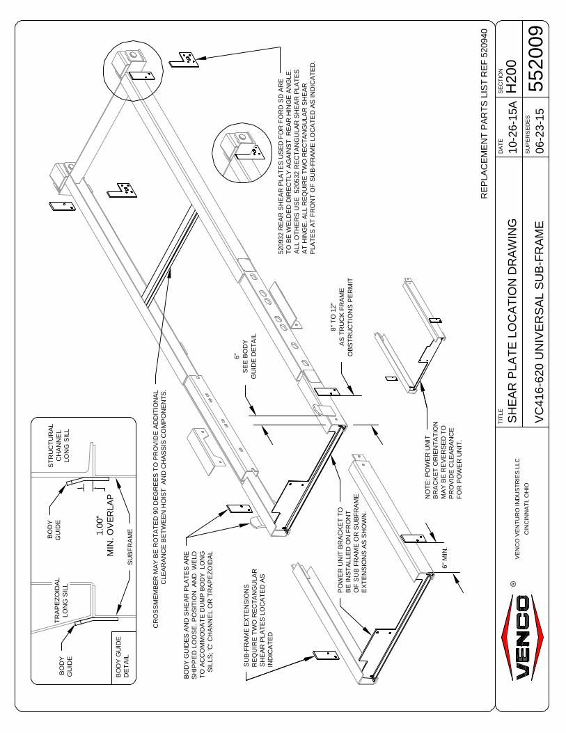
6"M
IN.
8"T
O12
"A
ST
RU
CK
FR
AM
EO
BS
TR
UC
TIO
NS
PE
RM
IT
6"S
EE
BO
DY
GU
IDE
DE
TA
IL
BO
DY
GU
IDE
SA
ND
SH
EA
RP
LAT
ES
AR
ES
HIP
PE
DLO
OS
E.P
OS
ITIO
NA
ND
WE
LDT
OA
CC
OM
MO
DA
TE
DU
MP
BO
DY
LON
GS
ILLS
;'C
'CH
AN
NE
LO
RT
RA
PE
ZO
IDA
L
5209
32R
EA
RS
HE
AR
PLA
TE
SU
SE
DF
OR
FO
RD
SD
AR
ET
OB
EW
ELD
ED
DIR
EC
TLY
AG
AIN
ST
RE
AR
HIN
GE
AN
GLE
.A
LLO
TH
ER
SU
SE
5205
32R
EC
TA
NG
ULA
RS
HE
AR
PLA
TE
SA
TH
ING
E.A
LLR
EQ
UIR
ET
WO
RE
CT
AN
GU
LAR
SH
EA
RP
LAT
ES
AT
FR
ON
TO
FS
UB
-FR
AM
ELO
CA
TE
DA
SIN
DIC
AT
ED
.
PO
WE
RU
NIT
BR
AC
KE
TT
OB
EIN
ST
ALL
ED
ON
FR
ON
TO
FS
UB
FR
AM
EO
RS
UB
FR
AM
EE
XT
EN
SIO
NS
AS
SH
OW
N.
CR
OS
SM
EM
BE
RM
AY
BE
RO
TA
TE
D90
DE
GR
EE
ST
OP
RO
VID
EA
DD
ITIO
NA
LC
LEA
RA
NC
EB
ET
WE
EN
HO
IST
AN
DC
HA
SS
ISC
OM
PO
NE
NT
S.
TR
AP
EZ
OID
AL
LON
GS
ILL
ST
RU
CT
UR
AL
CH
AN
NE
LLO
NG
SIL
L
BO
DY
GU
IDE
SU
B-F
RA
ME
EX
TE
NS
ION
SR
EQ
UIR
ET
WO
RE
CT
AN
GU
LAR
SH
EA
RP
LAT
ES
LOC
AT
ED
AS
IND
ICA
TE
D
1.00
"M
IN.O
VE
RLA
P
BO
DY
GU
IDE
NO
TE
:PO
WE
RU
NIT
BR
AC
KE
TO
RIE
NT
AT
ION
MA
YB
ER
EV
ER
SE
DT
OP
RO
VID
EC
LEA
RA
NC
EF
OR
PO
WE
RU
NIT
.
SU
BF
RA
ME
RE
PLA
CE
ME
NT
PA
RT
SLI
ST
RE
F52
0940
BO
DY
GU
IDE
DE
TA
IL

SECTIONDATE
SUPERSEDES
TITLE
VC416-620
H20011-05-15D
03-17-14C
MNTNG ILLUSTRATION
520608VENCO VENTURO INDUSTRIES LLC
CINCINNATI, OHIO
®
TRUCKFRAME
SUBFRAME
SUBFRAME
LOWER PIVOTANGLE
FIGURE 4b
TYP
FIGURE 4a
3/8
LOWER PIVOTANGLE
MOUNTING ANGLE
SUBFRAME MTG. BRACE
LOWER PIVOTTUBE
HOIST MNTG INST. VC416-6628 W/ SUB-FRAME

SECTIONDATE
SUPERSEDES
TITLE
PTO PUMP CABLE
-11-05-15B
03-17-14A
CABLE / HANDLE ASSY
620246VENCO VENTURO INDUSTRIES LLC
CINCINNATI, OHIO
®
(Step 1)Remove this screw.
(Step 3)Barrel nut.
(Step 5)Radius
(Step 2)Push button and pushhandle forward.
(Step 4)Return handle to centerposition.
Exposed when handleis pushed forward.
(Step 5)Shown after assembly.
ATTACHING 620129 CABLE TO 620131 / 132 HANDLEStep 1. Remove lowest screw & nut.Step 2. Depress red button on top of handle. Push handle forward and hold.Step 3. While holding handle, thread "barrel nut" into threaded hole in bottom and tighten.Step 4. Release handle. Handle should return to center positon.Step 5. Replace screw & nut, making sure that radius on cable end is aligned with screw hole. After tightening screw,
move handle forward and backward to make sure cable end is secure in console.
F O R WA
RD

SECTIONDATE
SUPERSEDES
TITLE
VC416-6628
-11-05-15B
03-17-14A
PTO PUMP CABLE INSTL
416755VENCO VENTURO INDUSTRIES LLC
CINCINNATI, OHIO
®
SCREW NUT BACK
RETURN NUT
SCREW FLANGESLEEVE BACK
SCREW FLANGESLEEVE FLUSH WITHFACE OF VALVE
SCREW NUTONTO ROD
ALIGN HOLES, INSERT PIN ANDSECURE (IF APPLICABLE)
SEAL PLATE (REF).HUSCO 5000 SERIES
FACE OF VALVE
VALVESPOOL
SCREW TERMINALEYE ON ROD
BOLT FLANGETO VALVE BODY
7
1
2
6
5
3
4
8
PTO PUMP CABLE INSTALLATION1. Thread 0.750-16 UNF jam nut entire length of threaded hub and onto cable.
2. Place flange on sleeve and turn flange / sleeve assembly entire length of threaded hub and onto cable.
3. Threade 0.250-28 UNF jam nut onto threaded rod until it bottoms.
4. Thread terminal eye onto threaded rod and bottom against jam nut, turn to align with spool slot and secure jam nutagainst terminal eye.
5. Slide terminal eye into slot in spool and align holes. Insert connecting pin and secure with cotter pin (if applicable).
6. With cable attached to valve and input device, thread the flange / sleeve assembly onto the threaded hub until it isflush with the valve face. When turning the flange / sleeve assembly, make sure the input device remains in the neutralposition.
7. Tighten the 0.750-16 UNF jam nut against the sleeve to lock in position.
8. Bring flange into position and bolt assembly to valve housing using two [2] socket head cap screws and two [2] splitlock washers under head and two [2] flat washers under lockwashers. Tighten screws sufficiently to flatten lockwashers or secure flange (see CAUTION).
CAUTION!
· Excessive torque or over-tightening will distort flange.

H2
00
SP
LIT
PU
MP
VC
41
6-6
628
08-0
1-1
7D
DA
TE
SE
CT
ION
SU
PE
RS
ED
ES
TIT
LE
416763
07-0
5-1
6C
VE
NC
OV
EN
TU
RO
IND
US
TR
IES
LLC
CIN
CIN
NA
TI,
OH
IO
®
DIR
EC
TIO
NA
LP
UM
PC
ON
FIG
UR
AT
ION
FO
RV
C4
16-6
20
BI-
DIR
EC
TIO
NA
LP
UM
PC
ON
FIG
UR
AT
ION
FO
RV
C6
28
&U
P
NO
TE
:F
OR
BI-
RO
TA
TIO
NA
LP
UM
PM
OU
NT
ING
AN
DH
OS
EC
ON
NE
CT
ION
INF
OR
MA
TIO
N,
SE
ED
WG
41
68
12
(IF
AP
PLIC
AB
LE
).
Model
VC
416
VC
516
VC
520
VC
620
VC
628
VC
5520
VC
6620
VC
6628
Contr
olC
able
&C
onso
le
Cylin
der
Up
Hose
Cylin
der
Dow
nH
ose
628041
(2)
628041
620909
(10'L
G,
3/8
HO
SE
)
FO
RV
C620
NO
N-S
F
416045
(7'L
G,
3/8
HO
SE
)
FO
RV
C620
SF
620910
(10'L
G,
1.0
0"
I.D
.)
FO
RV
C620
NO
N-S
F
416079
(7'L
G,
1.0
0"
I.D
.)
FO
RV
C620
SF
Pum
p/V
alv
e/T
ank
Pum
p(O
nly
)
416079
(7'L
G,
1.0
0"
I.D
.)S
uctio
nH
ose
(rese
rvoir
to
pum
p)
520088F
(10'L
G,
1-1
/4"
I.D
.)
416045
(7'L
G,
3/8
HO
SE
)H
igh
Pre
ssure
Hose
(pum
pto
valv
e)
620909
(10'L
G,
3/8
HO
SE
)
620125
-C
urv
ed
620124
-S
traig
ht
(2)
416045
416044
416045
520574
(2)
520574
416277
520594
620011
(9Q
UA
RT)
662077
(21
QU
AR
T)
NO
TE
:A
RR
OW
ON
PU
MP
HO
US
ING
IND
ICA
TE
DR
OT
AT
ION
DIR
EC
TIO
N.
FA
ILU
RE
TO
MA
TC
HP
TO
RO
TA
TIO
NW
ITH
PU
MP
RO
TA
TIO
NW
ILL
RE
SU
LT
INP
UM
PF
AIL
UR
E.
RE
SE
RV
OIR
&V
ALV
E
TR
UC
KF
RA
ME
HIG
HP
RE
SS
UR
EH
OS
E
SU
CT
ION
HO
SE
TO
PT
OTO
CA
B
CO
NT
RO
LC
AB
LE
&C
ON
SO
LE
UP
(300
0P
SI)
DO
WN
(1000
PS
I)
PU
MP
P/N
416
277
RE
SE
RV
OIR
&V
ALV
E
TR
UC
KF
RA
ME
HIG
HP
RE
SS
UR
EH
OS
E
SU
CT
ION
HO
SE
TO
PT
OTO
CA
B
CO
NT
RO
LC
AB
LE
&C
ON
SO
LE
UP
(300
0P
SI)
DO
WN
(1000
PS
I)
PU
MP
P/N
520
594
NO
TE
:R
ES
ER
VO
IR/
VA
LV
EM
OU
NT
ING
LO
CA
TIO
N&
MO
UN
TIN
GH
AR
DW
AR
ET
OB
ED
ET
ER
MIN
ED
BY
INS
TA
LL
ER
.

-S
PD
GH
OS
EC
ON
NE
CT
ION
DIA
GR
AM
VC
41
6-6
20
02-1
7-1
7F
DA
TE
SE
CT
ION
SU
PE
RS
ED
ES
TIT
LE
520621
02-1
5-1
7E
VE
NC
OV
EN
TU
RO
IND
US
TR
IES
LLC
CIN
CIN
NA
TI,
OH
IO
®
40
10
3H
OS
EC
LA
MP
Reserv
oir
H15
01
-0606
LO
W Con
trolV
alv
eIN
OU
TH
IGH
6M
P
12
MP
6F
PH
54
05
-12
06
(P/N
520087)
Pum
p
6M
P
6M
P
6F
PX
NO
TE
:A
RR
OW
ON
PU
MP
HO
US
ING
IND
ICA
TE
SR
OT
AT
ION
DIR
EC
TIO
N.F
AIL
UR
ET
OM
AT
CH
PT
OR
OT
AT
ION
WIT
HP
UM
PR
OT
AT
ION
WIL
LR
ES
UL
TIN
PU
MP
FA
ILU
RE
.
HO
TE
:O
nbo
then
ds,sl
ide
ho
se
cla
mp
over
hose
,th
en
fit
ho
se
over
nip
ple
an
duse
cla
mp
tosecu
re.
40
10
3
CLA
MP
HO
SE
6M
O
8M
O 6M
OX
6M
OX
6F
O
8M
P
4160
79
(VC
416
-52
0&
VC
620
SF
)
620
91
0(V
C6
20
NO
N-S
F)
41604
5(V
C416
-520
&V
C620
SF
)
62090
9(V
C620
NO
N-S
F)
6F
O
6M
O
4161
51-1
KIT
(VC
520/6
20)
INC
LU
DE
SIT
EM
S:
2,3
,41
22
3
4
41615
1K
IT(V
C4
16/5
16)
INC
LU
DE
SIT
EM
S:
2,3
41615
2K
IT(V
C41
6-6
20)
INC
LU
DE
SIT
EM
S:
1,2
H64
04
-0608
H64
04
-0608
H64
10
-0806
INL
ET
/S
UC
TIO
N
OU
TL
ET
/P
RE
SS
UR
E
FO
RM
UN
CIE
BR
AN
DP
UM
P(4
16277):
H6
40
5-1
01
2(P
/N416861)
H4
60
4-1
61
2(P
/N416862)
FO
RW
ILL
IAM
SB
RA
ND
PU
MP
(520092):
H6
40
5-1
21
2(P
/N416133)
H4
60
4-1
61
6(P
/N416095)
A B
BA
A B

SECTIONDATE
SUPERSEDES
TITLE
-
H20011-05-15D
03-17-14C
WILLIAMS PTO WARNING
416287VENCO VENTURO INDUSTRIES LLC
CINCINNATI, OHIO
®
The Gear Pump you have purchased is a single rotatation Gear Pump. The direction of rotation can be found by using theWilliams Machine and Tool Co.'s Model Number. Directly following the Model Number are the letters CCW or CW. Theseletters indicate the direction of rotation for the Gear Pump. CCW indicates a counter-clockwise rotation. CW indicates aclockwise rotation. Pump shaft rotation is determined by viewing pump from the shaft end.
Example: GP1538 CCW. The CCW indicates a counter-clockwise roation.
To verify the direction of rotation of your Gear Pump, perform the following steps:
1.) Locate the Part Number on the Gear Pump. The Part Number, Serial Number, and date code are located onthe rear of the Gear Pump.
2.) Part Numbers ending in an even number are clockwise roation (CW). Part Numbers ending in an oddnumber are counter-clockwise rotation (CCW).
Example: 1830201. The last number is 1 (an odd number). This indicates acounter-clockwise rotation (CCW).
The following chart specifies torque requirements for the SAE O' ring plugs installed into the side or rear ports of the GearPump. Any combination of inlet and outlet ports may be used, ie., inlet large rear port. outlet small side port; inlet largeside and outlet small rear ports; or both side ports or both rear ports. One inlet and one outlet part must be plugged forproper Gear Pump operation.
Date Serial #GP
Part Number
PORT SIZE (SAE) TORQUE (FT. LBS)3/4 - 16
7/8 - 14
1 - 1/16 - 121 - 5/16 - 121 - 5/8 - 12
15 - 2020 - 25
30 - 35
45 - 5065 - 70
C A U T I O N!
· The gear pump you have purchased is a single rotationGear Pump. Installation of this Gear Pump into a systemthat does not match the rotation of the Gear Pump mayresult in personal injury and/or property damage.
!
VENCO VENTURO INDUSTRIES LLC
CINCINNATI, OHIO
-GROUND CABLE INSTLLTN
HOIST HYD. POWER UNITS
10-09-15ADATE SECTION
SUPERSEDES
TITLE
09-25-09
HPU GROUNDING CABLE INSTALLATION
416640®
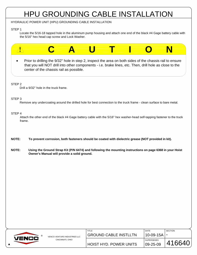
HYDRAULIC POWER UNIT (HPU) GROUNDING CABLE INSTALLATION
STEP 1Locate the 5/16-18 tapped hole in the aluminum pump housing and attach one end of the black #4 Gage battery cable withthe 5/16" hex head cap screw and Lock Washer.
STEP 2Drill a 9/32" hole in the truck frame.
STEP 3Remove any undercoating around the drilled hole for best connection to the truck frame - clean surface to bare metal.
STEP 4Attach the other end of the black #4 Gage battery cable with the 5/16" hex washer-head self-tapping fastener to the truckframe.
NOTE: To prevent corrosion, both fasteners should be coated with dielectric grease (NOT provided in kit).
NOTE: Using the Ground Strap Kit (P/N 6474) and following the mounting instructions on page 6368 in your HoistOwner's Manual will provide a solid ground.
C A U T I O N!
· Prior to drilling the 9/32" hole in step 2, inspect the area on both sides of the chassis rail to ensurethat you will NOT drill into other components - i.e. brake lines, etc. Then, drill hole as close to thecenter of the chassis rail as possible.

-H
YD
RA
ULI
CP
OW
ER
UN
ITG
RO
UN
DIN
G
ALL
AP
PLI
CA
TIO
NS
10-2
2-15
B
DA
TE
SE
CT
ION
SU
PE
RS
ED
ES
TIT
LE
6368
03-1
7-14
A
VE
NC
OV
EN
TU
RO
IND
US
TR
IES
LLC
CIN
CIN
NA
TI,
OH
IO
®
NO
TE
:Hyd
raul
icpo
wer
units
WIL
Lru
nw
itha
poor
grou
ndco
nnec
tion,
BU
Tth
ese
rvic
elif
eof
the
mot
oran
dco
ntro
lval
veco
ilsW
ILL
begr
eatly
redu
ced
unle
ssa
prop
ergr
ound
conn
ectio
nis
mad
e-
see
illus
trat
ion
belo
w.
Usi
ngth
eG
roun
dS
trap
Kit
(P/N
6474
)an
dfo
llow
ing
the
mou
ntin
gin
stru
ctio
nsbe
low
will
prov
ide
anef
fect
ive
grou
nd.
Hyd
raul
icP
ower
Uni
t
Res
ervo
irB
reat
her
Cap U
seth
etw
opr
ovid
ed3/
8-16
Thr
eade
dho
les
inth
eal
umin
umpu
mp
hous
ing
Tru
ckF
ram
eor
Sub
-Fra
me3/
8-16
x2-
3/4"
Long
Pla
ted
HH
CS
3/8
Lock
Was
her
Spa
cer
P/N
6081
2P
lcs
Cle
anT
ruck
Fra
me
toba
rem
etal
onbo
thsi
des
-4
plac
es.
App
lydi
elec
tric
grea
se(n
otpr
ovid
ed)
tobo
thsi
des
oftr
uck
fram
ean
dto
the
bolt
thre
ads.
DO
NO
TA
PP
LYT
HR
EA
DLO
CK
LIQ
UID
ST
OB
OLT
TH
RE
AD
S,A
ST
HE
YW
ILL
INS
ULA
TE
TH
EB
OLT
SF
RO
MT
HE
ALU
MIN
UM
PU
MP
HO
US
ING
.
Inst
allb
olts
and
torq
ueto
36ft/
lbs.
PR
OP
ER
GR
OU
ND
ING
OF
HY
DR
AU
LIC
PO
WE
RU
NIT
NO
N-S
UB
FR
AM
EA
PP
LIC
AT
ION
SO
NLY

H20
040
058M
/400
58M
HD
PO
WE
RU
NIT
VC
416-
628
12-0
9-15
G
DA
TE
SE
CT
ION
SU
PE
RS
ED
ES
TIT
LE
4168
0910
-09-
15F
VE
NC
OV
EN
TU
RO
IND
US
TR
IES
LLC
CIN
CIN
NA
TI,
OH
IO
®
SID
EV
IEW
TR
UC
KF
RA
ME
TO
PV
IEW
SIN
GLE
AC
TIN
GP
OW
ER
UN
IT-P
OW
ER
UP
/GR
AV
ITY
DO
WN
BE
SU
RE
PO
WE
RU
NIT
HA
SG
RO
UN
DT
OT
RU
CK
FR
AM
E.
SE
ED
RA
WIN
G41
6308
FO
RP
AR
TS
DO
WN
UP
BLA
CK
-H
OT
LEA
D
WH
ITE
-R
AIS
EH
OIS
T
GR
EE
N-
LOW
ER
HO
IST
CO
NN
EC
TT
OV
ALV
ES
OLE
NO
ID
+B
AT
TE
RY
CA
BLE
RE
TU
RN
HO
SE
-C
ON
NE
CT
TO
RO
DE
ND
OF
HY
DR
AU
LIC
CY
LIN
DE
R
BR
EA
TH
ER
/FIL
L-
RE
FP
RE
SS
UR
EH
OS
E-
CO
NN
EC
TT
OB
AS
EE
ND
OF
HY
DR
AU
LIC
CY
LIN
DE
R
3/8-
16H
EX
BO
LTS
PA
CE
R
GR
OU
ND
ING
ST
RA
PA
SS
YP
/N64
74.
NO
TE
:BE
SU
RE
TO
FO
LLO
WT
HE
"PR
OP
ER
GR
OU
ND
ING
OF
HY
DR
AU
LIC
PO
WE
RU
NIT
S",
DR
AW
ING
#63
68,
INT
HIS
MA
NU
AL.
4005
8M/M
HD
WIT
HM
ON
AR
CH
PU
SH
BU
TT
ON
CO
NT
RO
L
SO
LEN
OID
CO
VE
R
-41
6081
ME
DP
OW
ER
UN
IT
VC
416-
628
12-0
8-15
J
DA
TE
SE
CT
ION
SU
PE
RS
ED
ES
TIT
LE
4163
0710
-09-
15H
VE
NC
OV
EN
TU
RO
IND
US
TR
IES
LLC
CIN
CIN
NA
TI,
OH
IO
®
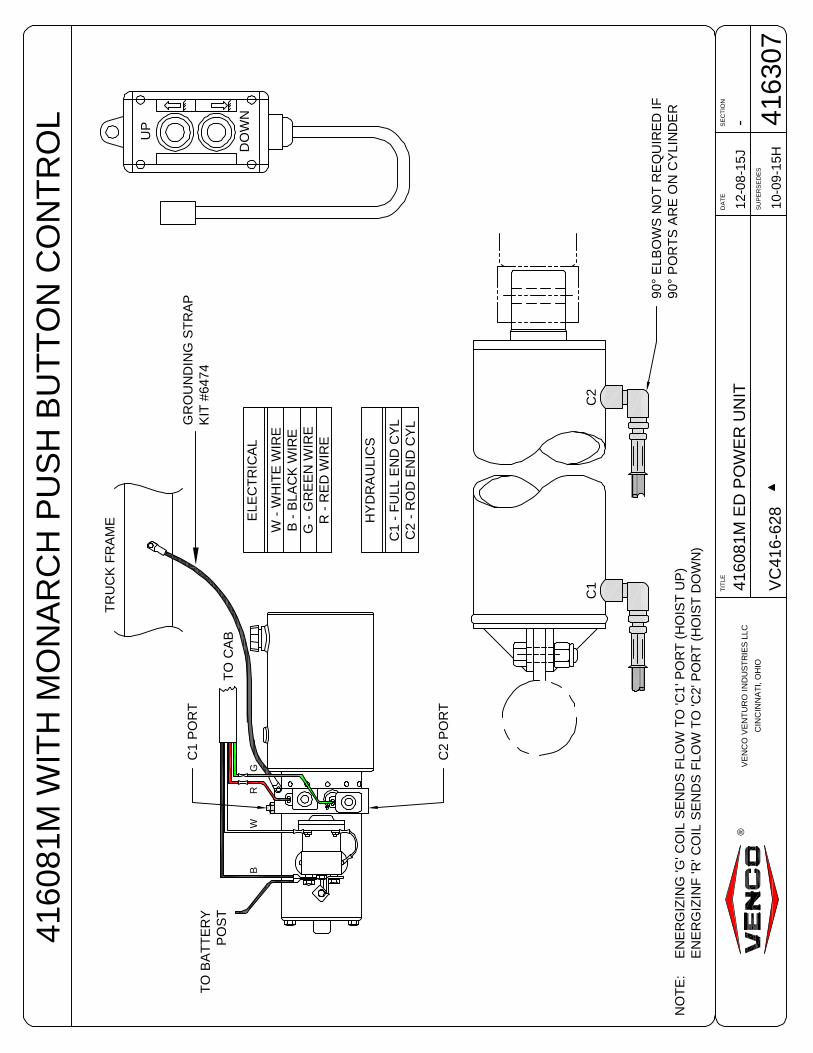
TR
UC
KF
RA
ME
4160
81M
WIT
HM
ON
AR
CH
PU
SH
BU
TT
ON
CO
NT
RO
L
TO
CA
B
GR
WB
C1
PO
RT
C2
PO
RT
TO
BA
TT
ER
YP
OS
T
C1
C2
UP
DO
WN
ELE
CT
RIC
AL
W-
WH
ITE
WIR
EB
-B
LAC
KW
IRE
G-
GR
EE
NW
IRE
R-
RE
DW
IRE
NO
TE
:E
NE
RG
IZIN
G'G
'CO
ILS
EN
DS
FLO
WT
O'C
1'P
OR
T(H
OIS
TU
P)
EN
ER
GIZ
INF
'R'C
OIL
SE
ND
SF
LOW
TO
'C2'
PO
RT
(HO
IST
DO
WN
)
HY
DR
AU
LIC
S
C1
-F
ULL
EN
DC
YL
C2
-R
OD
EN
DC
YL
90°
ELB
OW
SN
OT
RE
QU
IRE
DIF
90°
PO
RT
SA
RE
ON
CY
LIN
DE
R
GR
OU
ND
ING
ST
RA
PK
IT#6
474

-F
ILLI
NG
HY
DR
AU
LIC
RE
SE
RV
OIR
VP
/VC
6-62
8,T
RLR
313-
628
11-0
4-15
F
DA
TE
SE
CT
ION
SU
PE
RS
ED
ES
TIT
LE
4161
4008
-21-
15E
VE
NC
OV
EN
TU
RO
IND
US
TR
IES
LLC
CIN
CIN
NA
TI,
OH
IO
®

VE
NC
OV
EN
TU
RO
IND
US
TR
IES
LLC
CIN
CIN
NA
TI,
OH
IO
H20
0D
EC
AL
LOC
AT
ION
S
VC
416-
6628
,TR
LR41
6-66
28
10-2
7-15
FD
AT
ES
EC
TIO
N
SU
PE
RS
ED
ES
TIT
LE
4161
2810
-31-
14E
®
Incl
uded
with
your
Ven
coho
ista
reva
rious
dang
er,w
arni
ng,
and
caut
ion
deca
ls.T
hese
deca
lsm
ustb
epl
aced
inpr
omin
ent
loca
tions
soth
eyar
eea
sily
seen
and
read
ilyid
entif
iabl
e.T
his
illus
trat
ion
prov
ides
the
reco
mm
ende
dde
call
ocat
ions
.
TR
UC
K
FR
AM
E
R
1.
ST
AY
OU
TF
RO
MU
ND
ER
BO
DY
WH
EN
HO
IST
ISO
PE
RA
TIN
G.
2.
DU
RIN
GD
UM
PIN
GO
PE
RA
TIO
NS
,NO
ON
EM
US
TB
EA
LLO
WE
DT
OS
TA
ND
INO
RM
OV
ET
HR
OU
GH
TH
EA
RE
AW
HE
RE
TH
EB
OD
YA
ND
HO
IST
OP
ER
AT
EO
RIN
TO
AN
AR
EA
WH
ER
EA
NU
PS
ET
LOA
DM
IGH
TF
ALL
.3
.O
PE
RA
TO
RM
US
TR
EM
AIN
AT
CO
NT
RO
LS
INC
AB
DU
RIN
GD
UM
PIN
GO
PE
RA
TIO
NS
.4
.N
EV
ER
LE
AV
EB
OD
YR
AIS
ED
OR
PA
RT
LYR
AIS
ED
WH
ILE
VE
HIC
LEIS
UN
AT
TE
ND
ED
OR
WH
ILE
PE
RF
OR
MIN
GM
AIN
TE
NA
NC
EO
RS
ER
VIC
EU
ND
ER
BO
DY
,UN
LE
SS
BO
DY
ISB
RA
CE
DT
OP
RE
VE
NT
AC
CID
EN
TA
LLO
WE
RIN
G.
5.
IFH
OIS
TIS
EQ
UIP
PE
DW
ITH
PT
O,A
LWA
YS
DIS
EN
GA
GE
WH
EN
NO
TIN
US
EO
RW
HE
NM
OV
ING
VE
HIC
LE.
6.
DO
NO
TA
TT
EM
PT
TO
RA
ISE
AL
OA
DE
DB
OD
YW
HE
NV
EH
ICL
EIS
ON
UN
LEV
EL
GR
OU
ND
.
DA
NG
ER
!!
416
052-
B
R
OP
ER
AT
ION
OF
SA
FE
TY
PR
OP
DA
NG
ER
:D
ON
OT
US
ES
AFE
TYP
RO
PTO
SU
PP
OR
TA
LO
AD
ED
BO
DY
!1.
Rai
seb
ody
tosu
ffici
ent
heig
htan
dsh
utof
fall
pow
er.
2.U
nlo
ckP
RO
P(S
)and
perm
itto
swin
gfr
eely
toth
eve
rtica
lp
ositi
on.
3.U
sin
gin
side
-the
-ca
bco
ntro
ls,
low
erbo
dy
slow
lyun
tilP
RO
Pco
ntac
tslo
we
rsup
por
tbra
cket
.D
AN
GE
R:
DO
NO
TP
OW
ER
HO
IST
DO
WN
AF
TE
RC
ON
TA
CT
ISM
AD
EW
ITH
PR
OP
!T
odi
scon
tinu
eus
eof
safe
tyP
RO
P:
1.R
aise
bod
yto
suffi
cien
the
ight
and
shut
offa
llp
ower
.2.
Sw
ing
PR
OP
toS
TOR
ED
posi
tion
and
enga
gelo
ck.
4160
84-A
!!
DA
NG
ER
FA
ILU
RE
TO
OP
ER
AT
ES
AF
EL
YW
ILL
RE
SU
LT
INS
ER
IOU
SIN
JUR
YO
RD
EA
TH
!V
EH
ICL
EM
US
TB
EO
NL
EV
EL
GR
OU
ND
.D
ON
OT
US
EB
OD
YP
RO
PT
OS
UP
PO
RT
AL
OA
DE
DB
OD
Y.
DO
NO
TP
OW
ER
HO
IST
DO
WN
AF
TE
RC
ON
TA
CT
ISM
AD
EW
ITH
BO
DY
PR
OP
.
1.R
AIS
EB
OD
YT
OS
UF
FIC
IEN
TH
EIG
HT
TO
AL
LO
WB
OD
YP
RO
PT
OB
EE
XT
EN
DE
DA
ND
PO
SIT
ION
ED
.2.
LIF
TB
OD
YP
RO
PU
PU
NT
ILIN
DE
XIN
GP
INE
NG
AG
ES
IND
EX
ING
SL
OT
SA
ND
DR
OP
SIN
TO
TH
EL
OC
KE
DP
OS
ITIO
N.
3.L
OW
ER
BO
DY
CA
RE
FU
LL
YU
NT
ILT
HE
BO
DY
PR
OP
CO
NT
AC
TS
TH
EU
PP
ER
PIV
OT
TU
BE
.
1.R
AIS
EB
OD
YT
OS
UF
FIC
IEN
TH
EIG
HT
TO
DIS
EN
GA
GE
BO
DY
PR
OP
.2.
LIF
TB
OD
YP
RO
PO
UT
OF
IND
EX
ING
SL
OT
SA
ND
LO
WE
RT
OS
TO
WE
DP
OS
ITIO
N.
3.L
OW
ER
BO
DY
TO
CH
AS
ISR
AIL
S.
TO
EN
GA
GE
TO
STO
WBO
DY
PR
OP
OP
ER
AT
ING
INS
TRU
CTI
ON
S
DA
NG
ER
!
416
626-
A
FA
ILU
RE
TO
OP
ER
AT
ES
AF
EL
YW
ILL
RE
SU
LT
INS
ER
IOU
SIN
JUR
YO
RD
EA
TH
!V
EH
ICL
EM
US
TB
EO
NL
EV
EL
GR
OU
ND
.D
ON
OT
US
EB
OD
YP
RO
PT
OS
UP
PO
RT
AL
OA
DE
DB
OD
Y.
DO
NO
TP
OW
ER
HO
IST
DO
WN
AF
TE
RC
ON
TA
CT
ISM
AD
EW
ITH
BO
DY
PR
OP
.
1.R
AIS
EB
OD
YT
OS
UF
FIC
IEN
TH
EIG
HT
TO
AL
LO
WB
OD
YP
RO
PT
OB
EE
XT
EN
DE
DA
ND
PO
SIT
ION
ED
.2.
TU
RN
BO
DY
PR
OP
HA
ND
LE
UN
TIL
HA
ND
LE
MA
KE
SC
ON
TA
CT
WIT
HM
EC
HA
NIC
AL
ST
OP
.3.
LO
WE
RB
OD
YC
AR
EF
UL
LY
UN
TIL
TH
EB
OD
YP
RO
PC
ON
TA
CT
ST
HE
UP
PE
RP
IVO
TT
UB
E.
1.R
AIS
EB
OD
YT
OS
UF
FIC
IEN
TH
EIG
HT
TO
DIS
EN
GA
GE
BO
DY
PR
OP
.2.
TU
RN
BO
DY
PR
OP
HA
ND
LE
TO
LO
WE
RA
ND
ST
OW
BO
DY
PR
OP
.3.
LO
WE
RB
OD
YT
OC
HA
SIS
RA
ILS
.
TO
EN
GA
GE
TO
ST
OW
BO
DY
PR
OP
OP
ER
AT
ING
INS
TRU
CTI
ON
S
DA
NG
ER
!
416
624-
A
DA
NG
ER
! ST
AN
DC
LE
AR
WH
ILE
OP
ER
AT
ING 1
5254
-C
!W
AR
NIN
G!
WH
EN
LO
WE
RIN
GH
OIS
T,K
EE
PP
.T.O
.AN
DC
LU
TC
HE
NG
AG
ED
.V
EN
CO
4160
85
R
1.STA
Y OUT FROM
UNDERBODY WHEN
HOI ST ISOPERATING.
2.DURING
DUMPINGOPERATIO
NS, NOONE
MUSTBE ALLOWED
TOSTA
ND
INOR MOVE TH
ROUGHTH
EAREA W
HERE THE BODYAND HOIST
OPERATEOR IN
TOAN
AREA WHERE AN UPSETLOAD
MIGHTFA
LL.
3.OPERATO
RMUST REMAIN
AT CONTROLS IN
CABDURING
DUMPING
OPERATI ONS.
4.NEVER
LEAVE BODYRAISED OR
PARTLYRAIS
EDWHILE VEHICLE
IS
UNATTENDED OR W
HILEPERFORMIN
GMAIN
TENANCE OR SERVI C
E
UNDERBODY, UNLESS BODY IS
BRACED TO
PREVENT ACCIDENTAL LO
WERI NG.
5.IF
HOIST IS
EQUIPPED WI TH
PTO, ALW
AYS
DISENGAGE
WHENNOTIN
USE ORWHEN
MOVINGVEHI C
LE.
6.DO
NOT ATTEMPTTORAI S
E ALOADED BODY
WHEN VEHIC
LEIS
ONUNLE
VEL GROUND.
DANGER
!
!
416052-B
O P ER AT ION
O FSA FETY
PR O P
DANGER: DO NOT USE SAFETY PROP
TO
SUPPORTA LOADED BODY !
1.Raise
body tosuffic
ien t he ight and shut offallpower.
2.Unlock PROP(S ) and perm
it tosw
ing free ly tothe vertica
l
posit ion.
3.Usin
g inside-the-ca
b controls , lower body slowly until P
ROP
contactslower support bracke
t.
DANGER: DO
NOT POWER HOISTDOWNAFTER
CONTACT ISMADE WITHPROP !
To d iscont inue useof safety PROP:
1.Raise
body tosuffic
ien t he ight and shutoffall
power.
2.SwingPROP to
STORED position and engage
lock.
416084-A
!
!
DA
NG
ER
DA
NG
ER
!S
TAN
DC
LEA
R
WH
ILE
OP
ER
ATI
NG
152
54-
C
ILL
US
TR
AT
ION
FO
RR
EF
ER
EN
CE
ON
LY
VE
NC
O#4
1605
22
RE
Q'D
(1E
AC
HS
IDE
)
VE
NC
O#4
1608
41
RE
Q'D
FO
RE
AC
HS
IDE
SA
FE
TY
PR
OP
(SW
ING
-DO
WN
)
VE
NC
O#4
1662
61
RE
Q'D
FO
RE
AC
HS
IDE
SA
FE
TY
PR
OP
(IN
DE
XIN
G)
VE
NC
O#4
1662
41
RE
Q'D
FO
RE
AC
HS
IDE
SA
FE
TY
PR
OP
(LIN
KA
GE
)
VE
NC
O#1
5254
2R
EQ
'D(1
EA
CH
SID
E)
PD
MO
DE
LO
NLY
VE
NC
O #
41
66
24
→ 1
RE
Q'D
AF
FIX
TO
TR
UC
KD
AS
HB
OA
RD

516917
VENCO VENTURO INDUSTRIES LLC
CINCINNATI, OHIO
®
SECTION 250
OPERATION

SECTIONDATE
SUPERSEDES
TITLE
HOISTS
-09-03-15
-
OPERATOR - WARNINGS
520952VENCO VENTURO INDUSTRIES LLC
CINCINNATI, OHIO
®
READ THIS FIRSTOPERATOR - WARNINGS
► Read and fully understand entire owner's manual prior to operating this equipment.
► Do not dump while on uneven ground or if vehicle is uneven side to side. Dumping while uneven can cause vehicle
to overturn and cause property damage, equipment damage, serious injury or death.
► Stay clear of dump body when dumping. Moving vehicle parts or the moving load could cause serious injury or death.
► NEVER be under a raised body, and keep all others clear when raising body. Body could inadvertently fall causing
serious injury or death. Reference operator section for proper body prop use.
► Only allow qualified personnel to work on this equipment that understands its functions.
► Overloading Hoist can cause equipment malfunction, serious injury or death.
► NEVER operate this Hoist from outside the cab. This could cause serious injury or death.
► Make sure all warning and caution labels are legible and properly placed. Refer to the installation section for
placement and the replacement parts section for replacement decals.
► When performing maintenance, truck should be turned off and emergency brake set along with body prop set under
an UNLOADED body. NEVER prop a loaded body. Body could inadvertently fall, causing serious equipment
damage, personal injury or death.
► We strongly recommend you contact your truck equipment distributor to perform any type of repair or maintenance
on your equipment. If you do not have a local distributor, call VENCO VENTURO INDUSTRIES LLC for the closest
authorized distributor.

SECTIONDATE
SUPERSEDES
TITLE
VC 520-6628
H25011-05-15D
08-12-15C
MAINT. & OPER. INSTRC.
520079VENCO VENTURO INDUSTRIES LLC
CINCINNATI, OHIO
®
HOIST MAINTENANCE AND OPERATION INSTRUCTIONS
A. Hoist unit lubrication1. Lubricate all grease fittings on the hoist unit.2. Lubricate the rear hinge assembly.3. The hoist system should be serviced at the same time the truck is serviced, and sooner if the hoist unit is performing
heavy duty service.4. Pump Reservoir → Shall be filled with the recommended oil per the manufacturer's instructions. Periodically check
the hydraulic fluid and change when the truck engine oil is changed.
B. PTO Pump OperationWith the hoist and body completely installed, cycle the hoist several times to purge the hydraulic system of air.Operate the hoist system per the instructions in this manual and per the PTO manufacturer's instructions.
C A U T I O N!
· Do not operate the pump at more than 1000 RPM. Severe hoist system damage could result. The PTO speedto engine speed is governed by the gear ratio of the PTO drive installed in the truck transmission.
· For long service and safety from VC hoists, it is important that the following procedure be followed each timethe hoist is operated:
!
C A U T I O N!
· Do not drive the truck without first disengaging the PTO. Failure to disengage the PTO may result in severedamage to the pump and pump drive unit.
!
1. Engage the PTO from the truck cab and adjust the engine speed to obtain the correct PTO and lift speed desired.2. Pull the pump stick out. This will cause the hoist to raise.3. When the pump has reached its maximum capacity, the pump will bypass through the relief valve. To prevent the
pump from bypassing, push the pump knob to the center / middle position. Whenever the pump knob is centered, thehoist will stop moving and hold its position.
!C A U T I O N!
· Do not allow the pump to bypass for long periods of time, as this will put stress on the hydraulic and electricalsystems of the hoist.
4. To lower the hoist, push the pump stick in.NOTE: The Venco hoist powered by PTO drive pumps must be 'powered down'. Failure to 'power down' will cause
the reservoir to overflow.5. To lock the hoist against the truck frame when it is in the down position, push the pump knob in. When the pump
bypasses, place the knob n the center 'hold' position.6. Disengage PTO from transmission per the manufacturer's instructions.

D. Body prop(s): Federal Regualtion 1926.601, Paragraph10, requires the use of a body prop. Accordingly, all Venco hoistunits will have included as a standard item a body prop (safety strut). See Paragraphs D.1. & D.2. below.
1. The body prop is designed for use only when the truck body is empty. The purpose of the body prop is to provide asafety strut for use when maintenance or inspections are performed on an unloaded truck body in the raised position.
2. One [1] body prop shall be furnished for truck bodies up to and including 15 feet. For bodies longer than 15 feet inlength, two [2] body props should be used.
3. Venco hoists are equipped with one of three types of body props: Indexing, Swing-down or Linkage.The chart below shows the hoist model number and the corresponding body prop types available.
NOTE: For an illustration and operating instructions for each body prop type, see page 416645 in this manual.
4. Special Precautions for Swing-down Body Props -· Make sure the truck is parked on a flat level surface.· Use a suitable tool to pull out the Spring-loaded release pin (stowage device) to release the body prop from the
hoist frame. This will release the body prop allowing it to swing downward to a vertical position.· Make sure that the body prop is aligned with the body prop foot rest (the body prop will be in a vertical position),
then allow the truck body to move downward until the body prop is seated in the foot rest.NOTE: DO NOT POWER DOWN AFTER MAKING CONTACT WITH BODY PROP FOOT REST
· To disengage the body prop, raise the truck body until the body prop swings freely away from the foot pad. Usinga suitable tool, place the tool in a leverage position on the body prop and propel sharply to the left and upward (orto the right and upward) so that the locking pin can be compressed and seated in the locking pin hole. Makecertain the body prop is latched securely before the hoist is operated.
BODY PROP OPERATION GUIDE - GENERAL INFORMATION
SECTIONDATE
SUPERSEDES
TITLE
VC416 - VC6628 HOISTS
H25011-05-15A
5-28-14
BODY PROP OP. GUIDE
416644VENCO VENTURO INDUSTRIES LLC
CINCINNATI, OHIO
®
WARNING!
· Do not place arms, hands, or any partof the body between the trucklongitudinals (long beams) or movingparts to pull the body prop release /locking pin.
WARNING!
· Do not use the body prop(s) to supporta loaded truck body.
· Body prop(s) should be free swinging toa vertical position after the locking pin isreleased
WARNING!
· Read operation of safety strut and cautionlabels before operating the hoist.
WARNING!
· Use care when reseating the bodyprop(s) in the locked position.

SECTIONDATE
SUPERSEDES
TITLE
VC416 - VC620 HOISTS
H25012-18-15B
11-05-15A
BODY PROP OPERATIONS
416645VENCO VENTURO INDUSTRIES LLC
CINCINNATI, OHIO
®
FAILURE TO OPERATE SAFELY WILL RESULT IN SERIOUS INJURY OR DEATH!VEHICLE MUST BE ON LEVEL GROUND.DO NOT USE BODY PROP TO SUPPORT A LOADED BODY.DO NOT POWER HOIST DOWN AFTER CONTACT IS MADE WITH BODY PROP.
1. RAISE BODY TO SUFFICIENT HEIGHT TO ALLOW BODY PROPTO BE EXTENDED AND POSITIONED.
2. LIFT BODY PROP UP UNTIL INDEXING PIN ENGAGESINDEXING SLOTS AND DROPS INTO THE LOCKED POSITION.
3. LOWER BODY CAREFULLY UNTIL THE BODY PROPCONTACTS THE UPPER PIVOT TUBE.
1. RAISE BODY TO SUFFICIENT HEIGHT TO DISENGAGE BODYPROP.
2. LIFT BODY PROP OUT OF INDEXING SLOTS AND LOWER TOSTOWED POSITION.
3. LOWER BODY TO CHASIS RAILS.
TO ENGAGE
TO STOW
BODY PROP OPERATING INSTRUCTIONS
D A N G E R!
416626-A
FAILURE TO OPERATE SAFELY WILL RESULT IN SERIOUS INJURY OR DEATH!VEHICLE MUST BE ON LEVEL GROUND.DO NOT USE BODY PROP TO SUPPORT A LOADED BODY.DO NOT POWER HOIST DOWN AFTER CONTACT IS MADE WITH BODY PROP.
1. RAISE BODY TO SUFFICIENT HEIGHT TO ALLOW BODY PROPTO BE EXTENDED AND POSITIONED.
2. TURN BODY PROP HANDLE UNTIL HANDLE MAKESCONTACT WITH MECHANICAL STOP.
3. LOWER BODY CAREFULLY UNTIL THE BODY PROPCONTACTS THE UPPER PIVOT TUBE.
1. RAISE BODY TO SUFFICIENT HEIGHT TO DISENGAGE BODYPROP.
2. TURN BODY PROP HANDLE TO LOWER AND STOW BODYPROP.
3. LOWER BODY TO CHASIS RAILS.
TO ENGAGE
TO STOW
BODY PROP OPERATING INSTRUCTIONS
D A N G E R!
416624-A
R
OPERATION OF SAFETY PROPDANGER: DO NOT USE SAFETY PROP TO
SUPPORT A LOADED BODY !1. Raise body to sufficient height and shut off all power.2. Unlock PROP(S) and permit to swing freely to the vertical
position.3. Using inside-the-cab controls, lower body slowly until PROP
contacts lower support bracket.
DANGER: DO NOT POWER HOIST DOWN AFTERCONTACT IS MADE WITH PROP !
To discontinue use of safety PROP:1. Raise body to sufficient height and shut off all
power.2. Swing PROP to STORED position and engage
lock. 416084-A
! !D A N G E R
VC416 / VC516 / VC520 (STANDARD) INDEXING BODY PROP
VC516 / VC520 / VC620 (OPTIONAL) LINKAGE BODY PROP
VC620 (STANDARD) SWING-DOWN BODY PROP
INDEXING PIN
BODY PROP
BODY PROP OPERATION GUIDE - ILLUSTRATIONS & INSTRUCTIONS
TRUCKFRAME
NOTE: THE LINKAGE BODY PROP OPTION ALLOWS THE OPERATOR TOPOSITION THE BODY PROP FROM OUTSIDE OF THE BODY FOR ADDEDSAFETY. ASK YOUR SALES REPRESENTATIVE FOR MORE INFORMATION.
BODY PROP
BODY PROP HANDLE
NOTE: DUAL BODY PROPS ARE STANDARD ON HOIST MODEL VC6628. REFER TOTHE HOIST BODY PROP CONFIGURATION CHART ON DRAWING 416644 TODETERMINE THE AVAILABILITY OF DUAL BODY PROPS FOR OTHER HOIST MODELS.
SWING-DOWN BODY PROP
SPRING RELEASE HANDLE
LOWER SUPPORT BRACKET

516914
VENCO VENTURO INDUSTRIES LLC
CINCINNATI, OHIO
®
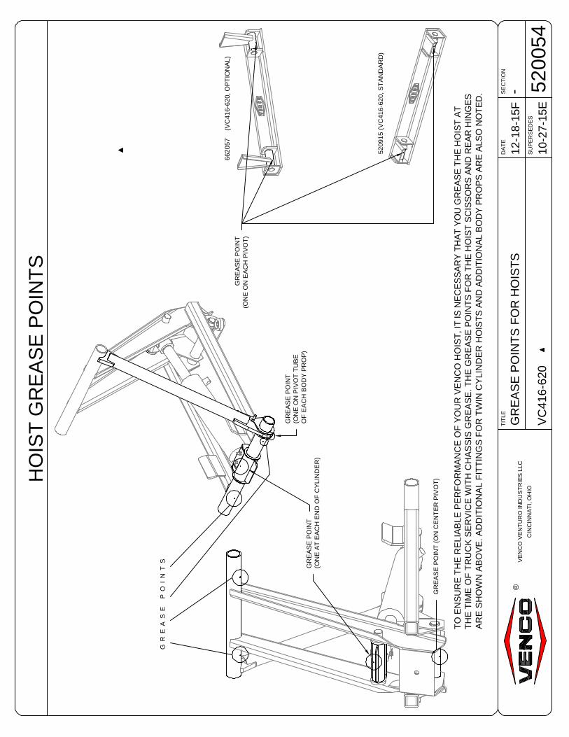
VE
NC
OV
EN
TU
RO
IND
US
TR
IES
LLC
CIN
CIN
NA
TI,
OH
IO
-G
RE
AS
EP
OIN
TS
FO
RH
OIS
TS
VC
416-
620
12-1
8-15
FD
AT
ES
EC
TIO
N
SU
PE
RS
ED
ES
TIT
LE
5200
5410
-27-
15E
®
HO
IST
GR
EA
SE
PO
INT
S
TO
EN
SU
RE
TH
ER
ELI
AB
LEP
ER
FO
RM
AN
CE
OF
YO
UR
VE
NC
OH
OIS
T,I
TIS
NE
CE
SS
AR
YT
HA
TY
OU
GR
EA
SE
TH
EH
OIS
TA
TT
HE
TIM
EO
FT
RU
CK
SE
RV
ICE
WIT
HC
HA
SS
ISG
RE
AS
E.T
HE
GR
EA
SE
PO
INT
SF
OR
TH
EH
OIS
TS
CIS
SO
RS
AN
DR
EA
RH
ING
ES
AR
ES
HO
WN
AB
OV
E.A
DD
ITIO
NA
LF
ITT
ING
SF
OR
TW
INC
YLI
ND
ER
HO
IST
SA
ND
AD
DIT
ION
AL
BO
DY
PR
OP
SA
RE
ALS
ON
OT
ED
.
GR
EA
SE
PO
INT
(ON
CE
NT
ER
PIV
OT
)
GR
EA
SE
PO
IN
TS
GR
EA
SE
PO
INT
(ON
EA
TE
AC
HE
ND
OF
CY
LIN
DE
R)
GR
EA
SE
PO
INT
(ON
EO
NP
IVO
TT
UB
EO
FE
AC
HB
OD
YP
RO
P)
6620
57(V
C41
6-62
0,O
PT
ION
AL)
5209
15(V
C41
6-62
0,S
TA
ND
AR
D)
GR
EA
SE
PO
INT
(ON
EO
NE
AC
HP
IVO
T)

516915
VENCO VENTURO INDUSTRIES LLC
CINCINNATI, OHIO
®

SECTIONDATE
SUPERSEDES
TITLE
VC/TRLR 416-6628
-11-05-15E
03-26-14D
DECAL LIST
628820VENCO VENTURO INDUSTRIES LLC
CINCINNATI, OHIO
PART NO.: 416626 (VC416,516 & 520 MODELS ONLY)
DECAL: SAFETY PROP OPERATION, 'INDEXING' ONLY
FUNCTION: To inform the operator of proper operation ofsafety prop.
QUANTITY: 1 For each safety prop.
PLACEMENT: On side of body closest to safetyprop(s).
®
PART NO.: 416052
DECAL: DANGER STAY CLEAR
FUNCTION: To provide operator with a summary of keyhoist operating procedures.
QUANTITY: 2
PLACEMENT: One on each side of body.
PART NO.: 416084 (VC620-VC6628 MODELS ONLY)
DECAL: SAFETY PROP OPERATION
FUNCTION: To inform the operator of proper operationof safety prop.
QUANTITY: 1 For each safety prop.
PLACEMENT: On side of body closest to safety prop(s).
PART NO.: 15254
DECAL: CAUTION STAND CLEAR
FUNCTION: To inform the operator to stay clear of body /hoist.
QUANTITY: 2
PLACEMENT: One on each side of truck frame.
PART NO.: 416085
DECAL: WARNING WHEN LOWERING
FUNCTION: To inform the operator to keep P.T.O. andclutch engaged when lowering the hoist.
QUANTITY: 1
PLACEMENT: Affixed to truck dashboard.
R
1. STAY OUT FROM UNDER BODY WHEN HOIST IS OPERATING.2. DURING DUMPING OPERATIONS, NO ONE MUST BE ALLOWED TO STAND
IN OR MOVE THROUGH THE AREA WHERE THE BODY AND HOISTOPERATE OR INTO AN AREA WHERE AN UPSET LOAD MIGHT FALL.
3. OPERATOR MUST REMAIN AT CONTROLS IN CAB DURING DUMPINGOPERATIONS.
4. NEVER LEAVE BODY RAISED OR PARTLY RAISED WHILE VEHICLE ISUNATTENDED OR WHILE PERFORMING MAINTENANCE OR SERVICEUNDER BODY, UNLESS BODY IS BRACED TOPREVENT ACCIDENTAL LOWERING.
5. IF HOIST IS EQUIPPED WITH PTO, ALWAYSDISENGAGE WHEN NOT IN USE OR WHENMOVING VEHICLE.
6. DO NOT ATTEMPT TO RAISE A LOADED BODYWHEN VEHICLE IS ON UNLEVEL GROUND.
DANGER! !
416052-B
R
O P E R A T I O N O F S A F E T Y P R O PDANGER: DO NOT USE SAFETY PROP TO
SUPPORT A LOADED BODY !1. Raise body to sufficient height and shut off all power.2. Unlock PROP(S) and permit to swing freely to the vertical
position.3. Using inside-the-cab controls, lower body slowly until PROP
contacts lower support bracket.
DANGER: DO NOT POWER HOIST DOWN AFTERCONTACT IS MADE WITH PROP !
To discontinue use of safety PROP:1. Raise body to sufficient height and shut off all
power.2. Swing PROP to STORED position and
engage lock. 416084-A
! !D A N G E R
FAILURE TO OPERATE SAFELY WILL RESULT IN SERIOUS INJURY OR DEATH!VEHICLE MUST BE ON LEVEL GROUND.DO NOT USE BODY PROP TO SUPPORT A LOADED BODY.DO NOT POWER HOIST DOWN AFTER CONTACT IS MADE WITH BODY PROP.
1. RAISE BODY TO SUFFICIENT HEIGHT TO ALLOW BODY PROP TOBE EXTENDED AND POSITIONED.
2. LIFT BODY PROP UP UNTIL INDEXING PIN ENGAGES INDEXINGSLOTS AND DROPS INTO THE LOCKED POSITION.
3. LOWER BODY CAREFULLY UNTIL THE BODY PROP CONTACTSTHE UPPER PIVOT TUBE.
1. RAISE BODY TO SUFFICIENT HEIGHT TO DISENGAGE BODYPROP.
2. LIFT BODY PROP OUT OF INDEXING SLOTS AND LOWER TOSTOWED POSITION.
3. LOWER BODY TO CHASIS RAILS.
TO ENGAGE
TO STOW
BODY PROP OPERATING INSTRUCTIONS
D A N G E R!
416626-A
! WARNING !WHEN LOWERING HOIST, KEEPP.T.O. AND CLUTCH ENGAGED.
VENCO 416085
DANGER!
STAND CLEARWHILE OPERATING
15254-C
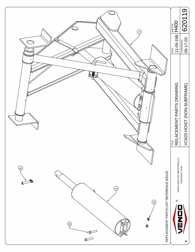
VE
NC
OV
EN
TU
RO
IND
US
TR
IES
LLC
CIN
CIN
NA
TI,
OH
IO
H40
0R
ELA
CE
ME
NT
PA
RT
SD
RA
WIN
G
VC
620
HO
IST
(NO
N-S
UB
FR
AM
E)
11-0
9-15
BD
AT
ES
EC
TIO
N
SU
PE
RS
ED
ES
TIT
LE
6201
1906
-17-
03
®
RE
PLA
CE
ME
NT
PA
RT
SLI
ST
RE
FE
RE
NC
E62
0120
1
2
4
3
5

SECTIONDATE
SUPERSEDES
TITLE
VC620
H40011-09-15C
05-23-06A
RPLCMNT PARTS LIST
620120VENCO VENTURO INDUSTRIES LLC
CINCINNATI, OHIO
®
ITEM PART NUMBER QTY. DESCRIPTION
1 620203 1 SCISSORS ASSEMBLY620203-SF 1 SCISSORS ASSEMBLY W/ SUB-FRAME
2 620907 1 HYDRAULIC CYLINDER3 !HHCS05013275-8 2 HEX HEAD CAP SCREW; 1/2-13 X 2-3/4" LG. GR. 84 !LNUT-05013 2 LOCK NUT; 1/2-13, NYLON
5 416545 1 5/8 X 3-1/2 CLEVIS PIN WITH RUE RING COTTER6 - - -7 - - -8 - - -9 - - -
10 - - -11 - - -12 - - -13 - - -14 - - -
15 - - -16 - - -17 - - -18 - - -19 - - -
20 - - -21 - - -22 - - -23 - - -24 - - -
25 - - -26 - - -27 - - -28 - - -29 - - -
30 - - -31 - - -32 - - -33 - - -34 - - -
REPLACEMENT PARTS DWG REF 620119
620119 REPLACEMENT PARTS LIST

1
5
2
3
46
VE
NC
OV
EN
TU
RO
IND
US
TR
IES
LLC
CIN
CIN
NA
TI,
OH
IO
H40
0R
EP
LAC
EM
EN
TP
AR
TS
DR
AW
ING
VC
620
W/O
PT
ION
AL
LIN
KA
GE
BO
DY
PR
OP
11-1
8-15
CD
AT
ES
EC
TIO
N
SU
PE
RS
ED
ES
TIT
LE
6201
3301
-31-
13A
®
VC
620
W/O
PT
ION
AL
LIN
KA
GE
BO
DY
PR
OP
RE
PLA
CE
ME
NT
PA
RT
SLI
ST
RE
FE
RE
NC
E62
0134
NO
TE
:T
HE
LIN
KA
GE
BO
DY
PR
OP
OP
TIO
NA
LLO
WS
OP
ER
AT
OR
TO
PO
SIT
ION
TH
EB
OD
YP
RO
PF
RO
MO
UT
SID
EO
FT
HE
BO
DY
FO
RA
DD
ED
SA
FE
TY
.AS
KY
OU
RS
ALE
SR
EP
RE
SE
NT
AT
IVE
FO
RM
OR
EIN
FO
RM
AT
ION
.
TR
UC
KF
RA
ME
109
8 7

SECTIONDATE
SUPERSEDES
TITLE
VC620 - OPT. LNKG PROP
H40011-10-15E
01-31-13C
RPLCMNT PARTS LIST
620134VENCO VENTURO INDUSTRIES LLC
CINCINNATI, OHIO
®
ITEM PART NUMBER QTY. DESCRIPTION
1 620203 1 SCISSORS ASSEMBLY2 620907 1 HYDRAULIC CYLINDER3 !HHCS05013275-8 2 HEX HEAD CAP SCREW; 1/2-13 X 2-3/4" LG. GR. 84 !LNUT-05013 2 LOCK NUT; 1/2-13, NYLON5 416545 1 5/8 X 3 1/2 CLEVIS PIN WITH RUE RING COTTER
6 620025 1 BODY PROP, WELDED ASSY.7 520638-ALT01 1 HANDLE, WELDED ASSY.8 520638-1 1 LINKAGE ROD ASSY., 31" LONG9 520633-2 1 LINKAGE ROD ASSY., 15" LONG10 520633-3 1 LINKAGE ROD ASSY., 55 1/4" LONG
11 - - -12 - - -13 - - -14 - - -15 - - -
16 - - -17 - - -18 - - -19 - - -20 - - -
21 - - -22 - - -23 - - -24 - - -25 - - -
26 - - -27 - - -28 - - -29 - - -30 - - -
31 - - -32 - - -33 - - -34 - - -35 - - -
REPLACEMENT PARTS DWG REF 620133
620133 REPLACEMENT PARTS LIST

H40
0R
EP
LAC
EM
EN
TP
AR
TS
DR
AW
ING
VC
620
(NO
N-S
UB
FR
AM
E)
11-1
0-15
B
DA
TE
SE
CT
ION
SU
PE
RS
ED
ES
TIT
LE
6201
1706
-17-
03
VE
NC
OV
EN
TU
RO
IND
US
TR
IES
LLC
CIN
CIN
NA
TI,
OH
IO
®
7
1 34
5
6
RE
PLA
CE
ME
NT
PA
RT
SLI
ST
RE
F62
0118
2
OP
TIO
NA
LH
ING
E
ST
AN
DA
RD
HIN
GE

SECTIONDATE
SUPERSEDES
TITLE
VC620 (NON SUB-FRAME)
H40011-10-15C
05-22-06A
RPLCMENT PARTS LIST
620118VENCO VENTURO INDUSTRIES LLC
CINCINNATI, OHIO
®
ITEM PART NUMBER QTY. DESCRIPTION
1 520920 2 FRAME MOUNTING ANGLE2 520915 1 REAR HINGE ASSEMBLY (STANDARD)3 !HHCS05012150 4 HEX HEAD CAP SCREW; 1/2-13 x 1-1/2" L4 !FWSH-050 8 FLAT WASHER; 1/2"5 !LWSH-050 4 LOCK WASHER; 1/2"
6 !HNUT-05013 4 HEX NUT; 1/2-137 662057 1 REAR HINGE ASSEMBLY (OPTIONAL)8 - - -9 - - -10 - - -
11 - - -12 - - -13 - - -14 - - -15 - - -
16 - - -17 - - -18 - - -19 - - -20 - - -
21 - - -22 - - -23 - - -24 - - -25 - - -
26 - - -27 - - -28 - - -29 - - -30 - - -
31 - - -32 - - -33 - - -34 - - -35 - - -
REPLACEMENT PARTS DWG REF 620117
620117 REPLACEMENT PARTS LIST

H4
00
RE
PLA
CE
ME
NT
PA
RT
S D
RA
WIN
G
VC
416
-620
UN
IVE
RS
AL
SU
B-F
RA
ME
08-1
6-1
9E
DA
TE
SE
CT
ION
SU
PE
RS
ED
ES
TIT
LE
520939
11-0
5-1
5D
VE
NC
O V
EN
TU
RO
IN
DU
ST
RIE
S L
LC
CIN
CIN
NA
TI, O
HIO
®
16
17
14
15
4
8
4
6
7
1
19
2
9
16
17
14
15
RE
PLA
CE
ME
NT
PA
RT
S L
IST
RE
F 5
20940
7
7
7
9
20
21
10
11
13
3
6
8
12
17
14
15
14
14
14
18
21 2
2 20
21 2
2
20
22
16
12
1
1N
OT
E:
ITE
M #
12,
BO
DY
GU
IDE
S A
RE
SH
IPP
ED
LO
OS
E;
PO
SIT
ION
AN
D W
ELD
TO
AC
CO
MM
OD
AT
E D
UM
P B
OD
Y L
ON
G S
ILLS
; 'C
' CH
AN
NE
L O
R T
RA
PE
ZO
IDA
L.
1
5
2
2
2
2
2U
PP
ER
& L
OW
ER
MO
UN
TIN
G A
NG
LE
S F
OR
VC
416
TH
RO
UG
H V
C5
20
ON
LY
.N
OT
E:
VC
620
MO
UN
TIN
G A
NG
LE
S A
RE
WE
LD
ED
TO
SC
ISS
OR
S A
SS
EM
BL
Y.

H4
00
RE
PLA
CE
ME
NT
PA
RT
S L
IST
VC
416
-620
UN
IVE
RS
AL
SU
B-F
RA
ME
08-1
6-1
9E
DA
TE
SE
CT
ION
SU
PE
RS
ED
ES
TIT
LE
520940
12-1
4-1
8D
VE
NC
O V
EN
TU
RO
IN
DU
ST
RIE
S L
LC
CIN
CIN
NA
TI, O
HIO
®
RE
PLA
CE
ME
NT
PA
RT
S D
WG
RE
F. 520939
22
8!F
WS
H-0
38
FL
AT
WA
SH
ER
; 3/8
"
21
8!L
NU
T-0
3816
LO
CK
NU
T;
3/8
-16
, N
YLO
N
20
8!H
HC
S03
816
125
HE
X H
EA
D C
AP
SC
RE
W (
HH
CS
); 3
/8-1
6 X
1-1
/4"
LG
, G
R. 5
19
2!L
WS
H-0
38
LO
CK
WA
SH
ER
; 3/8
"
18
2!H
HC
S03
816
075
HH
CS
; 3/8
-16
X 3
/4"
LG
, G
R. 5
17
12
!LW
SH
-050
LO
CK
WA
SH
ER
; 1/2
"
16
12
!HN
UT
-050
13-8
HE
X N
UT
; 1/2
-13
, G
R. 8
15
12
!HH
CS
05
01
3150-8
HH
CS
; 1/2
-13
X 1
-1/2
" LG
, G
R. 8
14
24
!FW
SH
-050
FL
AT
WA
SH
ER
; 1/2
"
13
2520925
JO
INE
R P
LA
TE
S
12
2520929
BO
DY
GU
IDE
S;
C-C
HA
NN
EL
& T
RA
PE
ZO
IDA
L
11
1520918
CR
OS
SM
EM
BE
R;
HY
D.
PO
WE
R U
NIT
MN
TN
G B
RA
CK
ET
10
1520919
CR
OS
SM
EM
BE
R;
SC
ISS
OR
S S
UP
PO
RT
92
520932
SH
EA
R P
LA
TE
, F
OR
D S
/D
82
520920
MO
UN
TIN
G A
NG
LE
; T
RU
CK
CH
AS
SIS
74
416220
CO
LL
AR
(A
LL P
IVO
T A
SS
EM
BLIE
S)
62
520923
UP
PE
R P
IVO
T A
SS
EM
BLY
; LE
FT
& R
IGH
T (
VC
416 -
VC
520)
54
520532
FR
AM
E T
IE D
OW
N B
RA
CK
ET
42
520930
LO
WE
R P
IVO
T A
SS
EM
BLY
; LE
FT
& R
IGH
T (
VC
416 -
VC
520)
31
520926-2
EX
TE
NS
ION
; 8
4"
SU
B-F
RA
ME
, R
IGH
T
21
520926-1
EX
TE
NS
ION
; 8
4"
SU
B-F
RA
ME
, LE
FT
11
520912
WE
LD
ED
AS
SE
MB
LY
; U
NIV
ER
SA
L S
UB
-FR
AM
E
ITE
MQ
TY
PA
RT
NO
.D
ES
CR
IPT
ION
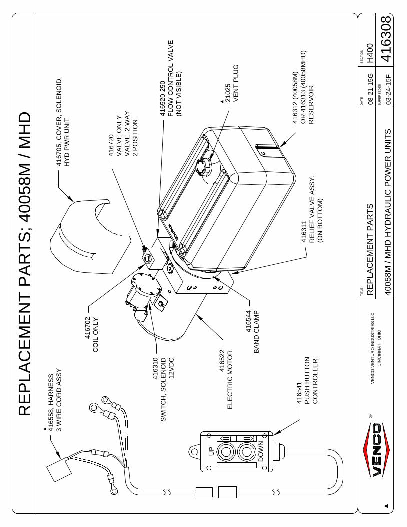
4165
41P
US
HB
UT
TO
NC
ON
TR
OLL
ER
2102
5V
EN
TP
LUG
4163
12(4
0058
M)
OR
4163
13(4
0058
MH
D)
RE
SE
RV
OIR
4167
20V
ALV
EO
NLY
VA
LVE
,2W
AY
2P
OS
ITIO
N
4163
10S
WIT
CH
,SO
LEN
OID
12V
DC
4163
11R
ELI
EF
VA
LVE
AS
SY
.(O
NB
OT
TO
M)
4165
44B
AN
DC
LAM
P
4167
02C
OIL
ON
LY
4165
20-2
50F
LOW
CO
NT
RO
LV
ALV
E(N
OT
VIS
IBLE
)
4165
22E
LEC
TR
ICM
OT
OR
RE
PLA
CE
ME
NT
PA
RT
S;4
0058
M/M
HD
UP
DO
WN
H40
0R
EP
LAC
EM
EN
TP
AR
TS
4005
8M/M
HD
HY
DR
AU
LIC
PO
WE
RU
NIT
S
08-2
1-15
G
DA
TE
SE
CT
ION
SU
PE
RS
ED
ES
TIT
LE
4163
0803
-24-
15F
VE
NC
OV
EN
TU
RO
IND
US
TR
IES
LLC
CIN
CIN
NA
TI,
OH
IO
®
4167
05,C
OV
ER
,SO
LEN
OID
,H
YD
PW
RU
NIT
4165
58,H
AR
NE
SS
3W
IRE
CO
RD
AS
SY
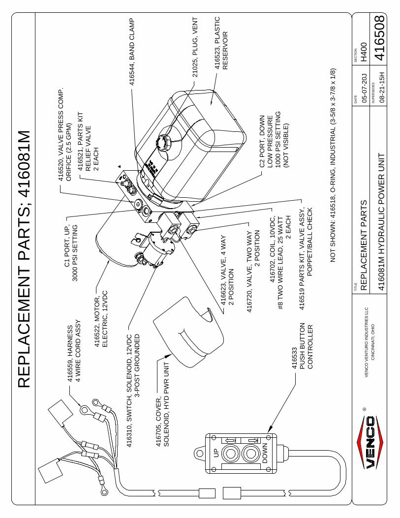
416533
PU
SH
BU
TT
ON
CO
NT
RO
LLE
R
RE
PL
AC
EM
EN
T P
AR
TS
; 416081M
UP
DO
WN
4165
23,
PL
AS
TIC
RE
SE
RV
OIR
2102
5,
PLU
G,
VE
NT
4167
02,
CO
IL,
10V
DC
,#
8 T
WO
WIR
E L
EA
D, 2
5 W
AT
T2
EA
CH
41672
0, V
ALV
E, T
WO
WA
Y2
PO
SIT
ION
41662
3, V
ALV
E, 4 W
AY
2 P
OS
ITIO
N
4165
44,
BA
ND
CLA
MP
416
31
0,
SW
ITC
H,
SO
LE
NO
ID, 12V
DC
3-P
OS
T G
RO
UN
DE
D
4165
22,
MO
TO
R,
ELE
CT
RIC
, 1
2V
DC
C1 P
OR
T,
UP
,3
000
PS
I S
ET
TIN
G
C2 P
OR
T,
DO
WN
LO
W P
RE
SS
UR
E1
000
PS
I S
ET
TIN
G(N
OT
VIS
IBLE
)
41652
1, P
AR
TS
KIT
RE
LIE
F V
ALV
E2
EA
CH
NO
T S
HO
WN
: 41
65
18
, O
-RIN
G,
IND
US
TR
IAL
(3-5
/8 x
3-7
/8 x
1/8
)
4165
19 P
AR
TS
KIT
, V
ALV
E A
SS
Y,
PO
PP
ET
/BA
LL C
HE
CK
4165
20,
VA
LV
E P
RE
SS
CO
MP
.O
RIF
ICE
(2.5
GP
M)
4167
05,
CO
VE
R,
SO
LE
NO
ID,
HY
D P
WR
UN
IT
H4
00
RE
PLA
CE
ME
NT
PA
RT
S
41
60
81
M H
YD
RA
ULIC
PO
WE
R U
NIT
05-0
7-2
0J
DA
TE
SE
CT
ION
SU
PE
RS
ED
ES
TIT
LE
416508
08-2
1-1
5H
VE
NC
O V
EN
TU
RO
IN
DU
ST
RIE
S L
LC
CIN
CIN
NA
TI, O
HIO
®
416
55
9,
HA
RN
ES
S4
WIR
E C
OR
D A
SS
Y

62
012
8
DO
UB
LE
AC
TIO
NH
OIS
T
MU
ST
BE
OP
ER
AT
ED
PO
WE
RU
PA
ND
PO
WE
RD
OW
N.
WH
EN
NO
TIN
OP
ER
AT
ION
LE
AV
EC
ON
TR
OL
INL
OC
KP
OS
ITIO
N.
HO
IST
UP
NE
UT
RA
LL
OC
K
HO
IST
DO
WN
CA
UT
ION
6201
29P
UM
PV
ALV
EC
ON
TR
OL
CA
BLE
6201
30C
AB
LEC
ON
NE
CT
OR
KIT
4167
51P
TO
CO
NT
RO
LLE
RB
RA
CK
ET
6201
31H
AN
DLE
,CU
RV
ED
LEV
ER
6201
32H
AN
DLE
,ST
RA
IGH
TLE
VE
R
!HH
CS
0311
8250
HH
CS
5/16
-18
X2-
1/2"
LG
!LN
UT
-031
18N
YLO
NLO
CK
NU
T5/
16-1
8
6201
28D
EC
AL
-D
IRE
CT
MO
UN
TP
UM
P
6201
26C
UR
VE
DH
AN
DLE
CA
BLE
AS
SE
MB
LY62
0127
ST
RA
IGH
TH
AN
DLE
CA
BLE
AS
SE
MB
LY
VE
NC
OV
EN
TU
RO
IND
US
TR
IES
LLC
CIN
CIN
NA
TI,
OH
IO
H40
0R
EP
LAC
EM
EN
TP
AR
TS
DW
G&
LIS
T
PT
OP
UM
PC
AB
LE
10-2
9-15
BD
AT
ES
EC
TIO
N
SU
PE
RS
ED
ES
TIT
LE
6202
4503
-17-
14A
®
CA
BLE
&C
ON
SO
LEK
ITS
;620
125
(CU
RV
ED
)&
6201
24(S
TR
AIG
HT
)

SECTIONDATE
SUPERSEDES
TITLE
HOISTS
-09-17-15
-
USER NOTES (1)
516919VENCO VENTURO INDUSTRIES LLC
CINCINNATI, OHIO
®
USER NOTES

SECTIONDATE
SUPERSEDES
TITLE
HOISTS
-09-17-15
-
USER NOTES (2)
516920VENCO VENTURO INDUSTRIES LLC
CINCINNATI, OHIO
®
USER NOTES

Revised: January 2015 12-00073_VNC3-D
VENCO HOISTS LIMITED WARRANTY POLICY Venco products are built to last…we guarantee them. As a purchaser of any new Venco product covered by warranty, you will receive 3 years of the most complete coverage available…and, at no added cost to you.
3-Year Limited Warranty Policy
This limited policy warrants new products of Venco to be free from defects in material and workmanship for a period of
three (3) years from date of original installation. OEM products or accessories purchased by Venco as part of or offered
with our product will carry the OEM manufacturer’s respective warranty. Our warranty covers:
Repair or replacement of product
Labor to repair or replace product
Freight to return and/or replace product
We shall not be liable for any contingent liabilities arising out of the improper function of any products. Warranty shall
become void if the product is improperly installed, modified, damaged, abused or used for application other than
intended use. Venco hoists are designed for and intended to be used on stationary trucks dumping on firm and level
ground. Spreading applications and/or shock unloading are strictly prohibited and will void this warranty. There is no
warranty of merchantability, fitness for a particular purpose, warranty arising from course of dealing or usage of trade,
or any other implied or expressed warranty, except as made specifically herein. This warranty supersedes all previous
warranties, written or implied.
Warranty Claims
Venco Venturo Industries LLC will make a good faith effort for prompt correction or other adjustment with respect to any product, which proves to be defective after our inspection and within the warranty period. Before any repairs are attempted or before returning any product, your Venco Distributor is required to obtain a warranty claim number. This number is necessary for any claim to be considered. To obtain a warranty claim number, Venco requires the model and serial number. Only authorized Venco Distributors can perform warranty. For the name and address of your local Venco Distributor call the Warranty Claim Department - 513-772-8448. WARNING - It is the responsibility of the installer to ensure the installation is completed according to the manufacturer's recommendations, ensure the ultimate user understands how to operate product in a safe manner, and understands the need for regular service and maintenance by an authorized Venco Distributor. No modifications or alterations may be made to any Venco product without the expressed written consent of Venco Venturo Industries LLC. Installation of any Venco product must be done by an authorized Venco Distributor, to the standards of the industry; including maintenance, service and affixing of all instruction, safety and warning decals. Users should be instructed as to the safe operation at time of delivery. Maintenance, service, operation and safety warning decals are available on request from Venco Venturo Industries LLC.
VENCO VENTURO INDUSTRIES LLC 12110 BEST PLACE | CINCINNATI, OHIO 45241
P: 800-226-2238 | F: 513-326-5427 www.venturo.com