Embed Size (px)
Citation preview

System Prefabricated Composite Bridge Girder

General information / PreambleComposite construction distinguishes itself by the use of the materi-als steel and concrete adapted to loads and material requirements and by its high degree of prefabrication together with consequent construction efficiency.
One field of composite construction is the economic crossing of large span widths with low weights and easily manageable as-sembly sections combining justifiable construction heights and the elimination of falseworks. In modern steel bridge construction two construction methods are compared to prestressed concrete con-struction in view of their economic competitiveness – pure steel construction with orthotropic carriageway slabs and prefabricated composite method with an effective concrete carriageway slab. A pure orthotropic structure is usually only economically efficient for large span widths or in some particular cases.
Steel composite construction, characterised by optimised com-bination of positive features of the materials steel and concrete, convinces already at span widths starting at 25 m under certain conditions compared to prestressed concrete construction. Advan-tages of this method are also evident for construction stages dur-ing which an interim composite can be used or for span areas of continuous girders where a double composite action is applicable.Because of the high bending tensile resistance, steel girders are typically used as main bearing elements. For the carriageway the good properties of concrete in case of compressive stresses are taken advantage of. So, individual point loads can be distributed onto the surface of the main bearing elements. Steel composite constructions allow to build slender, aesthetic bridges in a short time. These bridges are robust load-bearing structures, and efficient and simple in terms of maintenance and inspection.
Road bridge over motorway A8 west, integral frame bridge; span width 47.25 m; crossing angle; 84.4 gon; slenderness at span centre 1 / 48.5; slenderness at frame corner 1 / 22.8
New construction of road bridge over the river Saale part of federal highway B181 Merseburg. Single-span frame in VFT® construction method for a 4-lane road bridge over the river ‘Saale’, 2 x 4-web open composite cross section, steel girder S355J2+N as solid web welded girders with variable web height, prefabri-cated VFT® upper chord C45 / 55, upper chord width 2.56 m; span width 55.40 m, slenderness at span centre 1 / 31.7; slenderness at frame corner 1 / 21.7; thickness of cast in-situ concrete 0.25 m; crossing angle 100 gon, abutments founded each on 8 bored piles ∅ 1.20 m; assembly weight per VFT-girder around 69 tons
16.53
4.44
3.873.87 3.87
4.44

VFT® construction methodThe VFT® method follows the successful construction type of pre-fabricated elements in prestressed method and adds the advan-tages of composite construction.
In general a welded girder, open (double T girder) or U-shaped box section, is affixed to the upper chord with an up to 3 m wide concrete compression flange at the plant. This flange stabilises the composite girder during transport as well as mounting in horizontal direction and entails due to its composite effect a significant stiff-ness increase in vertical direction already in the construction stage (first composite).
At the construction site, the girders are placed by mobile cranes next to each other on temporary support frames/yokes (arranged in front of the abutments and pile shafts), directly on the support benches or in case of integral frame structures on the frame stan-chions. Assembly of the girders is realised with a clear joint distance of 2 cm between the concrete upper chords.
The wide concrete upper chords act, aside from structural aspects, as formwork for construction of the cast in-situ concrete supple-ment connecting the composite girders to the cast in-situ cross gird-ers in the area of the bearing axes in transversal direction to form a monolithic bridge deck. From a structural point of view, concreting of the cast in-situ supplements on site creates a second composite that augments the stiffness of the composite girders as longitu-dinal members to absorb secondary dead loads as well as traffic loads. Because of the high transversal stiffness of the composite girders, no stiffening connections are necessary for construction of the cast in-situ slab.In case of conventional composite the loads occurring during construction of the cast in-situ carriageway slab are distributed only to the steel girder, as the first composite is not
1 2 3 4
yet achieved at this moment. Only after setting of the upper chord’s concrete, the loads from bridge deck completion and traffic act on the composite cross section. Upper and lower chord of the steel girders are thus to be dimensioned and stiffened with view to con-creting loads of the carriageway slab.
In case of the VFT® girders, however, the loads act already onto the complete early (first) composite. The total dead weight moments are absorbed by the very stiff composite cross section. Consider-able material savings can be made for the structural steel compared to traditional composite construction. More savings are made by eliminating struts in the webs and especially by eliminate stabilis-ing connections in the construction stage. The VFT® girder shows thus analogies to common prestressed concrete girder construction but with significantly lower weights. Road transport is possible for length up to 60 m, water transport depending on the length of the lock chamber for length of up to 100 m.
6
5
1 VFT® girder as open fully welded girder with constant construction height
2 VFT® girder as open fully welded girder with variable construction height, preferably for continuous girders / semi-integral or integral bridges
3 VFT® girder as tightly-welded box section with variable construction height
4 Further development of open fully welded VFT® girder, without upper chord/without head bolts; with composite dowel strip
5 Comparison transport/assembly weight of prefabricated prestressed con-crete elements (T-form) with VFT® girders
6 Viaduct Oberharthmannsreuth: use of 2 x 2 web open fully welded VFT® girders with a construction height of 2.65 m, width of prefabricated upper chord 3.10 m, use of formwork traveller for construction of composite slab, thickness of cast in-situ layer 29 – 34 cm; assembly weight max. 80 t (with 850 t mobile crane)
Cast in-situ concrete supplement C35 / 45 (thickness 25 cm up to 40 cm)
Small upper chord in steel to house shear studs
Prefabricated upper chord in concrete C50 / 60
Weldeed steel girder (open web, alternative hollow box girder)
Welded steel girder S355Air tight hollow box girder
Vaulted to pier / abutment
Vaulted to pier / abutment
Bottom chord, dimensioning up to static requirements(chord width in general 0.60 - 0.80 m)
Welded steel girder S355 with composite dowel strip
Prefabricated elements < 100 t
Prefabricated elements > 100 t
VFT®
Not transportable
Length [meter]
Weight [tons]
180
160
140
120
100
80
60
40
20
0
20.00 25.00 30.00 35.00 40.00 45.00
At the beginning of the 1990s, composite bridges have been de-veloped based on rolled girders, coupled by cast in-situ cross gird-ers, thus not requiring additional welding to achieve a continuous effect. The VFT® girder method with its prestressed concrete pre-fabricated flange fits perfectly into this system. In the individual bearing axes cast in-situ cross girders are arranged, connecting the VFT® girders to form continuous girders. Compressive forces from the steel flanges are distributed by contact joints, transverse forces by shear studs. Simple reinforcement connections at the prefabricated concrete compression chord allow tensile force coupling already in the construction stage, the remaining rein-forcement parts can be integrated into the cast in-situ supple-ment for the continuous effect. In the same way VFT® girders can be integrated into framing corners of integral structures. Welded
joints at the steel girders are of course possible too, but are the exception in practice compared to simple coupling methods by cast in-situ cross girders. Steel workers are thus not required on the construction site. Final cross girders should be planned in any case made of concrete so as to avoid the creation of walkable and thus difficult abutments, which are in general required for final cross girders made of steel for maintenance reasons.
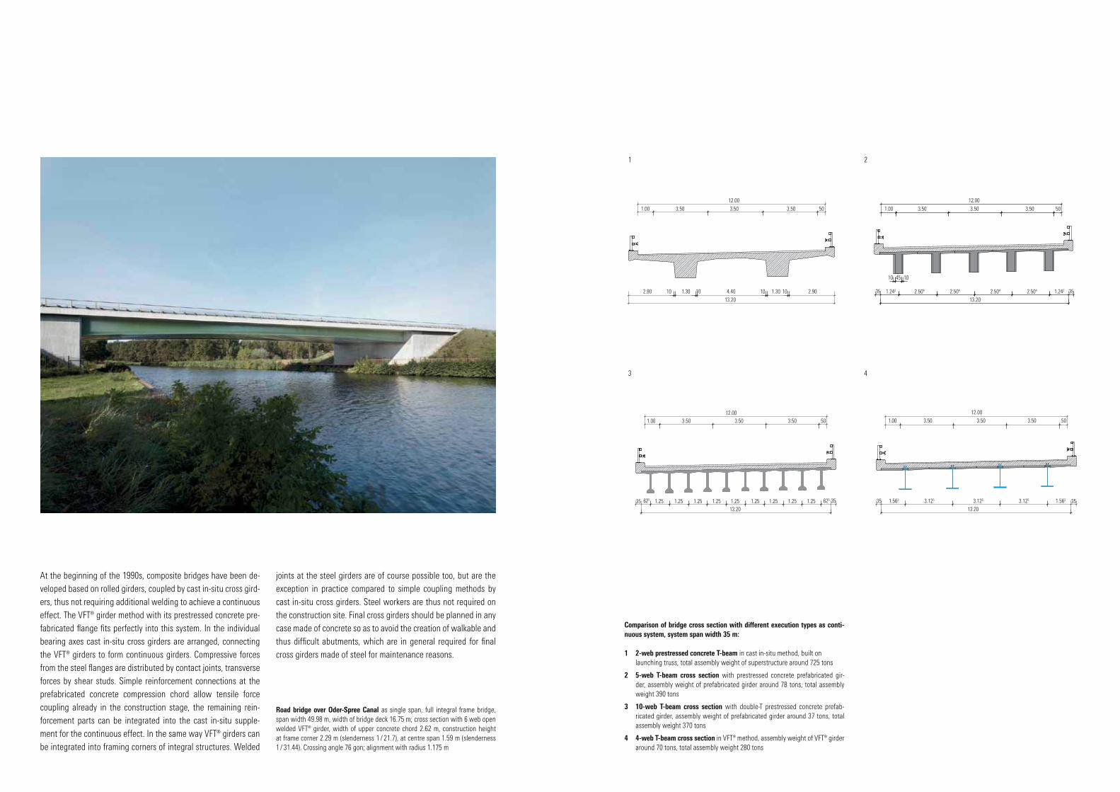
Comparison of bridge cross section with different execution types as conti-nuous system, system span width 35 m:
1 2-web prestressed concrete T-beam in cast in-situ method, built on launching truss, total assembly weight of superstructure around 725 tons
2 5-web T-beam cross section with prestressed concrete prefabricated gir-der, assembly weight of prefabricated girder around 78 tons, total assembly weight 390 tons
3 10-web T-beam cross section with double-T prestressed concrete prefab-ricated girder, assembly weight of prefabricated girder around 37 tons, total assembly weight 370 tons
4 4-web T-beam cross section in VFT® method, assembly weight of VFT® girder around 70 tons, total assembly weight 280 tons
Road bridge over Oder-Spree Canal as single span, full integral frame bridge, span width 49.98 m, width of bridge deck 16.75 m; cross section with 6 web open welded VFT® girder, width of upper concrete chord 2.62 m, construction height at frame corner 2.29 m (slenderness 1 / 21.7), at centre span 1.59 m (slenderness 1 / 31.44). Crossing angle 76 gon; alignment with radius 1.175 m
3.1251.563 1.563
1.00
1.00
3.50
3.50
3.50
3.50
12.00
13.20
2.90 2.901.301.30 4.401010 1010
12.00
3.50
3.50
50
50
35 353.125 3.125
13.20
1
1.00
13.20
625 1.25 1.251.251.25 1.251.25 1.251.25 1.25 625
3.50 3.5012.00
3.50 50
35 35
3
1.00
1.242 2.504 2.504
13.20
2.504 2.504 1.242
3.50 3.50
12.00
3.50 50
35
10 1045
35
2
4

In addition to these advantages, other aspects can be emphasised as the segmental construction method makes generally prestressed concrete bridges more attractive: the high degree of prefabrication together with low weight, larger span widths for the same con-struction heights and the possibility to choose new structural sys-tems. The quality of the construction elements is considerably high-er as VFT® girders are fabricated under the same conditions without weather influences at the plant (in case of particular boundary con-ditions, it is of course also feasible to produce the concrete upper chord on site before mounting the girders in lateral position at the steel girders). The prefabricated girders are delivered to the site en bloc and are mounted with a light crane compared to prestressed concrete girders. The concrete flange forms early on a connection to the steel girder. Continuous systems, but also composite fram-
ing systems, can be achieved purely by reinforcement connections. Especially composite framing systems allow very high slenderness at the centre of the span. Altered geometrical conditions, created by the deliberate elimination of centre piles or by the selection of larger clearances, can be solved with VFT® girders, which span con-siderably larger span widths at remaining construction height.
Construction with maintained trafficDuring new construction and replacement of bridges within the existing traffic network, the highest priority is to cause as less in-terference as possible in traffic flow on roads, operation of railway lines and water ways. When bridging traffic routes by concrete con-struction method, prefabricated prestressed concrete girders with span widths of up to 30 m for railway bridges and up to 40 m for
road bridges or concrete bridges are erected on site by means of falseworks of launching trusses. The economically efficient use of (above lying) launching trusses necessitates a minimum number of spans to be constructed and limits span widths to around 50 m at maximum. Falseworks require additional temporary construction height, which in general is not given for inner-urban crossings. Dif-ficult scaffoldings and lowering devices for temporary constructions above the actual gradient are the consequence and generate further costs, influencing negatively the competitiveness of these bridges.The advantage of composite bridges in VFT® construction method becomes now evident as the prefabricated composite method with high stiffness and moderate assembly weights (or significantly low-er weight compared to prefabricated elements made of prestressed concrete) allows the construction of large span widths without es-
sential interference in the operation. So, for example, when bridg-ing motorway lanes or multi-tracked railway lines, in general the construction of a centre support, whose erection is always linked to significant traffic interferences, is not necessary as it is for con-crete construction method. The extraordinarily high degree of pre-fabrication of the VFT® girders shortens construction time of such structures and therefore the period of operational interference in traffic spaces. The high stiffness from the first composite of girder prefabrication leads to high slenderness already in the assembly stage and allows the conception of wide-spanning framing struc-tures, predestined to bridge existing traffic routes. Prefabricated composite girder structures for bridge construction can be imple-mented almost without any interference and thus interruption of the existing traffic network.
1
2 5
4 6 9
7
83
1 Completed fully welded girder (open cross section) on storing yard of steelwork company, ready for transport to the prefabrication plant for fabri-cation of reinforced concrete upper chord
2 Formwork table for fabrication of upper chord, fabrication of outer cantilever arms, front side with curvature analogous to S-shaped alignment
3 Construction of reinforced concrete upper chord at prefabrication plant, view on steel girder in the formwork, reinforcement of upper chord and shear studs
4 VFT®-girder coming from the prefabrication plant
5 Transport of around 50 m long VFT®-girders by road; VFT® girders with transversal transport securing
6 Mounting of 4, around 80 t heavy VFT®-girders for a road bridge above the Flake Canal; span width 56.25 m, bridge deck width 10.0 m; crossing angle 65 gon; construction height at centre 1.82 m, construction height at framing cor-ner 2.60 m; slenderness at span centre 1/30.9; slenderness framing corner 1/21.6
7 Mounting of around 70 ton heavy VFT® girders with two mobile cranes above navigation canal
8 Railway bridge over the Teltow Canal; mounting of in total seven 49.5 m long and 64 t heavy VFT® girders as single span girder over a 7-track railway site during nightly close-off with 800 t mobile crane, construction height VFT® girders 1.75 m, cast in-situ supplement 0.25 m
9 Continuous girder bridge in VFT® method; assembly situation over railway instal-lations, girder on temporary supports; girders coupled by cast in-situ cross girders

Combining functionality and aestheticsComposite bridge systems distinguish themselves by their high functionality and economic efficiency in view of construction ma-terial use. In addition to functionality, bridges are also distinctive architectural elements. With regard to high vertical stiffness from the first composite, distinctive transversal stiffness from the upper concrete flange and the possibility of covering positive corner mo-ments by simple reinforcement connections, prefabricated com-posite bridges are extremely suitable for the design of framing bridges and make it possible to build very slender and aesthetic bridges due to their fixed connection of the superstructure to the abutments. The steel load-bearing members are built in changea-ble construction heights with vaulted webs and represent the force
flow of the load-bearing structures also optically in the structure. A demanding design together with high functionality and eco-nomic efficiency are the defining characteristics of steel compos-ite structures and can be ideally represented with the composite girder method.
1
2
3
4
5
28.20 20.94
63.50
55.40
27.30
36.00
17.38
1+2 Overpass of federal highway B19 over motorway A3 Nuremberg – Frank-furt in the course of expansion of the motorway from 4 to 6 lanes; junction Hei-dingsfeld. New construction of road bridge crossing the 6-lane motorway, 2 hard shoulders and junction lanes. Comparison of common road bridge as continuous girder over 3 spans in prestressed concrete method with bearings and joints to form a fully integral frame bridge without supports, with bearings and joints in VFT® construction method, VFT®-girders of variable construction height with tightly welded steel box sections, span widths 63.50 m
3 New construction of road bridge over the river Saale part of federal highway B181 Merseburg. Single-span frame in VFT® construction method for a 4-lane road bridge over river ‘Saale’, 2 x 4-web open composite cross section for bridge deck width 21,60 between guard rail; steel girder steel girders S355J2+N as solid web welded girders with variable web height, prefabricated VFT® upper chord C45 / 55, upper chord width 2.56 m, span width 55.40 m; slenderness at span centre 1 / 31.7; slenderness at framing corner 1 / 21.7; thickness of cast in-situ concrete 0.25 m; crossing angle 100 gon, abutments founded each on 8 bored piles ∅ 1.20 m; assembly weight per VFT®-girder around 69 tons
4 Single-span frame in VFT® construction method for a 2-lane road bridge over a 2-tracked railway, 4-web open composite cross section, steel girders S355J2+N as solid web welded girders with variable web height, prefabri-cated VFT® upper chord C45/55, upper chord width 2.50 m, span width 27.30 m; slenderness at span centre 1 / 32.9; slenderness at framing corner 1/18.8; thickness of cast in-situ concrete 0.25 m; crossing angle 100 gon, abutments founded each on 4 bored piles ∅ 0.90 m; assembly of VFT®-girders during nightly railway close-off
5 New construction of road bridge over railway part of road J.-S.-Bach-Strasse, Fürstenwalde. Single-span frame in VFT® construction method for a 3-lane road bridge over a 4-tracked railway, 6-web open composite cross section, steel girders S355J2+N as solid web welded girders with vari-able web height, prefabricated VFT® upper chord C45/55, upper chord width 2.82 m, span width 55.40 m; slenderness at span centre 1 / 32.7; slenderness at framing corner 1 / 20.0; thickness of cast in-situ concrete 0.25 m; crossing angle 79 gon, abutments on shallow foundations; assembly of VFT®-girders during nightly railway close-off VFT® girders on low loader with lateral transport securing
Efficient construction costs and maintenanceThe decision for a suitable bridge construction method is often influ-enced by the aspect of construction costs. However, already in this early phase factors such as user costs, running costs for inspection and maintenance as well as costs for a later following load capacity increase are to be taken into consideration.
Construction costsPrefabricated composite constructions excel by their economically efficient load-bearing system and optimum material combination already for the first composite as well as by optimised material use. Considerable material savings of structural steel can be made com-pared to traditional composite construction. Quantities of only 100 to 180 g structural steel per m2 bridge surface suffice in general. Hence,
these systems are in terms of price a competitive alternative to pre-stressed concrete or reinforced concrete constructions for small and medium span widths and especially compared to prefabricated gird-ers made of prestressed concrete, whose application is limited due to their high dead weight to span widths of at maximum 30 to 40 m. Because of the high degree of prefabrication of prefabricated com-posite girders and the possibility to bridge large span widths without intermediate support, expenses for additional foundation and pile constructions can be saved and the construction time reduced.
User costsThe use of bridges in VFT® method minimises during execution the interference in the running traffic of the existing traffic network and
reduces thus delays and interruptions of the traffic flow. These user costs are often underestimated and are seldom taken account of, even though they can exceed construction costs many times over, for examples, in case of congestions and railway delays.
Running costs for inspection and maintenance During the life cycle of a structure, costs for maintenance, reno-vation and inspection arise; experience shows that these costs amount annually to around 0.7 to 1.5 % of construction costs, de-pending largely on the construction type and equipment of each structure. On integral bridges, framing corners replace bearing and carriageway joints, and are in general subject to especially high maintenance efforts. Composite bridges are easy to inspect and,
if necessary, can be strengthened to achieve higher load-bearing capacity by simply welding on steel flanges onto the steel girders.The high degree of prefabrication when constructing composite bridges at the plant under equal production conditions guarantees highest production quality in view of geometry, keeping of toler-ances, formation of welding seams and corrosion protection. In the context of durability and serviceability, essential advantages to minimise maintenance and renovation costs are achieved. With re-gard to construction costs as well as running costs, steel composite structures are exceptionally economically efficient systems. Prefab-ricated composite construction decreases construction and main-tenance costs. Construction times are reduced and a high quality standard is guaranteed.
1
2
3
4
5
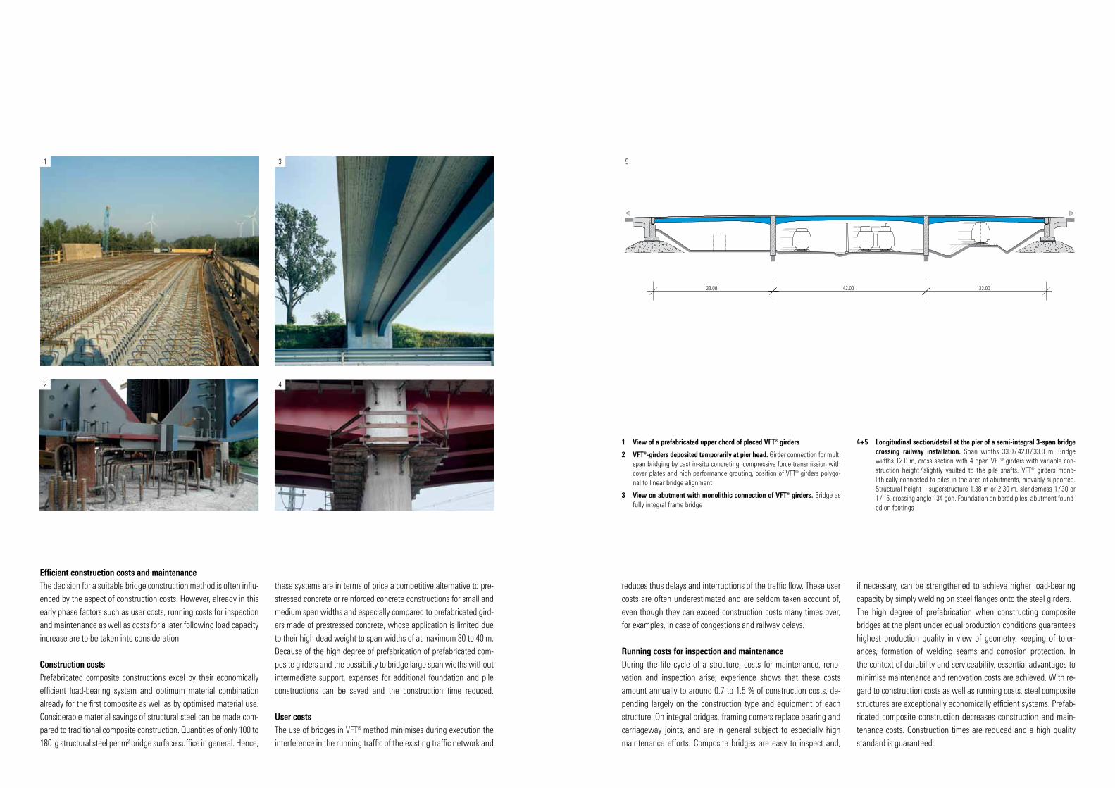
1 View of a prefabricated upper chord of placed VFT® girders
2 VFT®-girders deposited temporarily at pier head. Girder connection for multi span bridging by cast in-situ concreting; compressive force transmission with cover plates and high performance grouting, position of VFT® girders polygo-nal to linear bridge alignment
3 View on abutment with monolithic connection of VFT® girders. Bridge as fully integral frame bridge
4+5 Longitudinal section/detail at the pier of a semi-integral 3-span bridge crossing railway installation. Span widths 33.0 / 42.0 / 33.0 m. Bridge widths 12.0 m, cross section with 4 open VFT® girders with variable con-struction height / slightly vaulted to the pile shafts. VFT® girders mono-lithically connected to piles in the area of abutments, movably supported. Structural height – superstructure 1.38 m or 2.30 m, slenderness 1 / 30 or 1 / 15, crossing angle 134 gon. Foundation on bored piles, abutment found-ed on footings
33.00 42.00 33.00

Advantages of VFT® construction- In addition to prefabricated girders made of prestressed con-
crete, VFT® girders can be used for single-span and continuous systems, on viaducts and especially framing systems.
- The concept of VFT® girders meets requirements of modern bridge construction methods in particular. In general, the VFT® girder cross section is implemented in analogy to prefabricated prestressed concrete girders.
- In case of VFT® girders the materials concrete and steel are ap-plied specifically. The need of structural steel is thus minimised significantly due to the first composite applied already at the plant, and entails very economically efficient production costs.
- The low weight of the VFT® girders and the high bending stiff-ness reveals new dimensions for span widths of prefabricated bridges. The already high bending stiffness in the construction stage results in low deformations when constructing the cast in-situ supplement; the high bending stiffness in the final stage allows small dimensions of the structure and slender, aesthetic structures.
- The VFT® method allows the implementation of integral framing structures. The elimination of joints and bearings in these fram-ing systems reduces maintenance efforts and minimises joint-induced noise emissions. Particularly for railway bridges special driving dynamic advantages are the result of small angles of the final tangent. Moreover, VFT® frame bridges can be erected as one unit parallel to an existing railway line and be launched lat-erally during short close-offs.
- The VFT® construction method makes it possible to erect very oblique crossing structures.
- Wide concrete flanges as girder upper chords of the composite cross section result in high transversal stiffness, so that struts in the webs or temporary stiffening connections in the construction stage are not necessary. Furthermore, the concrete upper chords serve as monolithic formwork for the later following cast in-situ concrete.
- The high degree of prefabrication of the VFT® girders reduces works on the construction site, leading, together with low trans-port and mounting weights, to economically efficient assembly,
combining efficient assembly periods and minor traffic interfer-ences. The results are significant advantages for the application above and for operational routes of railway and road traffic.
- The extensive prefabrication of VFT® girders at the plant guar-antees a high quality standard and high robustness, resulting together with well accessible steel girders and monolithic cast in-situ slab in low maintenance costs.
- The VFT® method does in general not require steel works on the construction site.
- The connection of the VFT® girders to cast in-situ concrete gird-ers above the piles or at the abutments is implemented by indi-vidually formed pile caps, shear studs and compression plates.
- The distribution of the support moment in case of continuous girder systems in the final construction stage is achieved by sim-ply feasible tie rod bar connections.
- The VFT® method allows continuous and thus economically ef-ficient post concreting of the cast in-situ slab.
- The VFT® method provides high load-bearing reserves by good stress rearrangement effects.
6
51
2
3
4
1+2 Viaduct Oberharthmannsreuth part of motorway A93. Span widths 34.80 + 3 x 44 + 34.80 m; use of 2 x 2 web open fully welded VFT® girders with a construction height of 2.65 m, width of prefabricated upper chord 3.10 m, use of formwork traveller for construction of composite slab. Bridge widths 2 x 14.68 m.
3+4 Road bridge over river Werra. Integral 3-span bridge. Span widths 30,5 + 40 + 30,5 m; 4-web open composite cross section, steel girder steel girders as solid web welded girders with variable web height, prefabricated VFT® upper chord C45 / 55, upper chord width 2,56 m, slenderness at span centre 1 / 29,2; slenderness at framing corner 1 / 17,0; thickness of cast in-situ con-crete 0,25 m; abutments founded each on 3 bored piles ∅ 0,90 m
5 Beauty of composite bridges
6 Bridge over motorway A96. Integral frame bridge with 2 VFT® girders as tightly welded box sections, monolithically connected to abutment projec-tions, span width 36 m

Railway bridgesBecause of the very high and concentrated railway loads, railway bridges have to be designed very stiff so as to guarantee wheel/rail contact for usual operational speeds. Especially in the structural design of steel and steel composite bridges, in addition to struc-tural considerations, dynamics are particularly important to meet requirements of flawless and durable use.
In general, composite construction is exceptionally suitable for rail-way bridges as composite bridges can be built economically with low deformations, have a long life cycle and are inspection-friendly.
A conscientious conception of structural details and a force flow oriented, notch and deformation-low cross section are part of this concept. These concerns, which are very important for durability and serviceability, are to be put into practice all throughout imple-mentation of fabrication at the plant as well as assembly on the construction site.
The majority of newly erected railway bridges, especially within urban area, are nowadays constructed as frame structures made of reinforced concrete (built in-situ in lateral position with trans-versal launching) or as composite rolled girders in concrete. For all span widths, the system of prefabricated composite girders offers ideal precondition for an efficient integral railway bridge. The steel load-bearing structure together with the prefabricated reinforced concrete track slab especially in hybrid frames allows slender yet
1
2
3
Left above: Renewal of several existing railway bridges in VFT® method over the River Saale and nearby flooding area. The single-tracked river crossing was in-tended as vaulted 2-span structure with 2 x 32.50 m span width, conventionally on bearings. The alternative offer of an integral frame structure in VFT® method with a construction height at the centre of the span of 1.95 m (slenderness 1 / 15.64) and of 2.85 m at the framing corner (slenderness 1 / 10.70) with two VFT® girders (width of concrete chord 3.50 m, thickness of cast in-situ supplement 0.30 m) was implemented. By the framing effect the breaking forces of the train are much bet-ter distributed into the foundations than by a system with bearings, resulting in significant savings for the bored pile foundation. The bridge over the flooding area was also designed as single-span, fully integral frame with 34.40 m span width in VFT® construction method
Left below: Bridge over the Teltow Canal in Berlin. See explanation at fig. 3
1 Railway bridge Schongau. Single-track railway bridge with 3 spans in semi-integral construction method (superstructure monolithically connected to piles) VFT®-girders as open fully welded girder with torsion connections (curved outline)
2 Railway bridge Schongau; cross section
3 Bridge over the Teltow Canal in Berlin. Single-span frame in VFT® construc-tion method for a 2-tracked railway bridge over water ‘ Teltow Canal’, 4-web open composite cross section, steel girders S355J2+N as solid web welded girders with variable web height, prefabricated VFT® upper chord C45/55, upper chord width 2.50 m, span width 42.50 m; slenderness at span centre 1 / 21.8; slenderness at framing corner 1/14.4; thickness of cast in-situ con-crete 0.40 m; crossing angle 79 gon, abutments founded each on 5 bored piles ∅ 1.50 m; assembly weight per VFT®-girder around 75 tons
7.12
10.75
1.16
35 351.605 1.605 1.605 1.605
1.60
1.1620
1015
202.20 2.20
Road bridges: prestressed concrete
Road bridges: VFT-girder
Railway bridges: VFT-girder
Railway bridges:reinforced concrete
60
Slenderness (-)
50
40
30
20
10
00.0 5.5 10.0 15.0 20.0 25.0 30.0 35.0 40.0 45.0 50.0 55.0 60.0 65.0 70.0 Length (m)
1 5
4
2
3
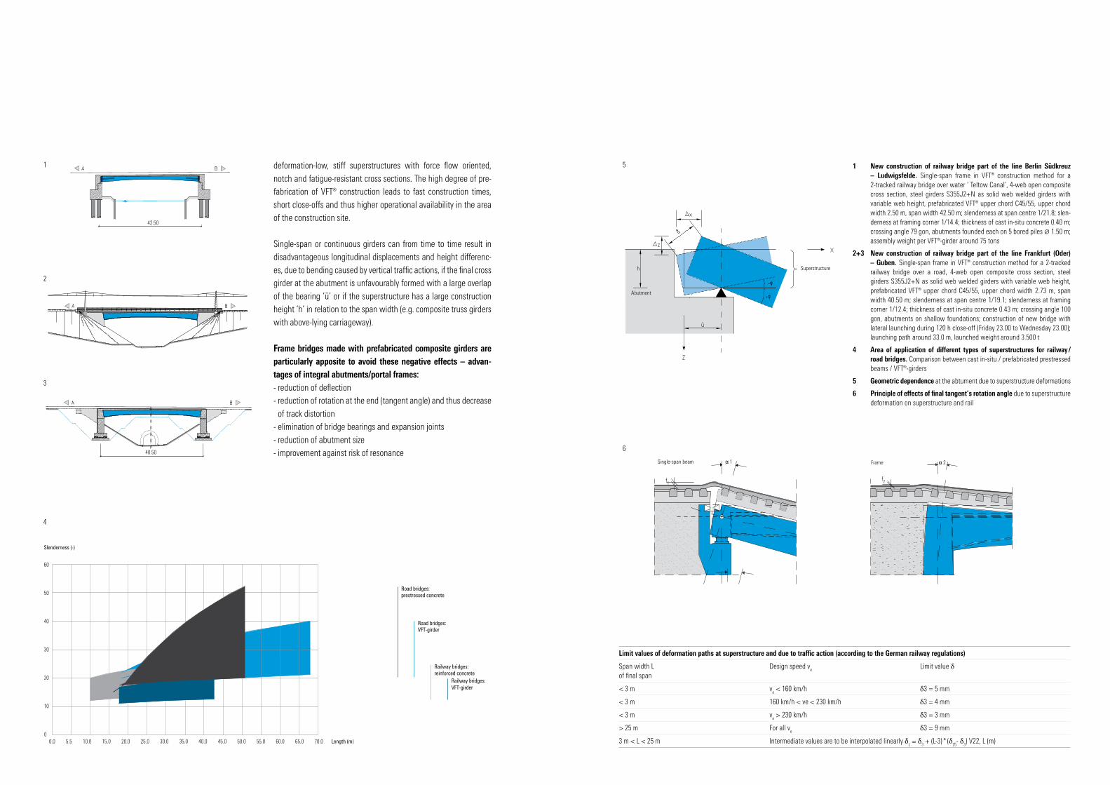
deformation-low, stiff superstructures with force flow oriented, notch and fatigue-resistant cross sections. The high degree of pre-fabrication of VFT® construction leads to fast construction times, short close-offs and thus higher operational availability in the area of the construction site.
Single-span or continuous girders can from time to time result in disadvantageous longitudinal displacements and height differenc-es, due to bending caused by vertical traffic actions, if the final cross girder at the abutment is unfavourably formed with a large overlap of the bearing ‘ü’ or if the superstructure has a large construction height ‘h’ in relation to the span width (e.g. composite truss girders with above-lying carriageway).
Frame bridges made with prefabricated composite girders are particularly apposite to avoid these negative effects – advan-tages of integral abutments/portal frames:- reduction of deflection- reduction of rotation at the end (tangent angle) and thus decrease
of track distortion- elimination of bridge bearings and expansion joints- reduction of abutment size- improvement against risk of resonance
42.50
1 New construction of railway bridge part of the line Berlin Südkreuz – Ludwigsfelde. Single-span frame in VFT® construction method for a 2-tracked railway bridge over water ‘ Teltow Canal’, 4-web open composite cross section, steel girders S355J2+N as solid web welded girders with variable web height, prefabricated VFT® upper chord C45/55, upper chord width 2.50 m, span width 42.50 m; slenderness at span centre 1/21.8; slen-derness at framing corner 1/14.4; thickness of cast in-situ concrete 0.40 m; crossing angle 79 gon, abutments founded each on 5 bored piles ∅ 1.50 m; assembly weight per VFT®-girder around 75 tons
2+3 New construction of railway bridge part of the line Frankfurt (Oder) – Guben. Single-span frame in VFT® construction method for a 2-tracked railway bridge over a road, 4-web open composite cross section, steel girders S355J2+N as solid web welded girders with variable web height, prefabricated VFT® upper chord C45/55, upper chord width 2.73 m, span width 40.50 m; slenderness at span centre 1/19.1; slenderness at framing corner 1/12.4; thickness of cast in-situ concrete 0.43 m; crossing angle 100 gon, abutments on shallow foundations; construction of new bridge with lateral launching during 120 h close-off (Friday 23.00 to Wednesday 23.00); launching path around 33.0 m, launched weight around 3.500 t
4 Area of application of different types of superstructures for railway / road bridges. Comparison between cast in-situ / prefabricated prestressed beams / VFT®-girders
5 Geometric dependence at the abtument due to superstructure deformations
6 Principle of effects of final tangent’s rotation angle due to superstructure deformation on superstructure and rail
6
Single-span beam
f1
α 1 Frame α 2
f2
Limit values of deformation paths at superstructure and due to traffic action (according to the German railway regulations)
Span width Lof final span
Design speed ve Limit value δ
< 3 m ve < 160 km/h δ3 = 5 mm
< 3 m 160 km/h < ve < 230 km/h δ3 = 4 mm
< 3 m ve > 230 km/h δ3 = 3 mm
> 25 m For all ve δ3 = 9 mm
3 m < L < 25 m Intermediate values are to be interpolated linearly δL = δ
3 + (L-3) * (δ
25- δ
3) V22, L (m)
Abutment
Superstructure
40.50

Title
: SHO
RT C
UTS
GmbH
, des
ign
+ k
omm
unik
atio
n