Embed Size (px)
Citation preview

Open Journal of Radiology, 2011, 1, 28-37 doi: 10.4236/ojrad.2011.12005 Published Online December 2011 (http://www.SciRP.org/journal/ojrad)
Copyright © 2011 SciRes. OJRAD
Synchrotron Refraction Enhanced Tomography of an Intact Common Marmoset (Callithrix jacchus)
Toshihiro Sera1,2, Hideo Yokota2, Sakiko Nakamura2, Kentaro Uesugi3, Masato Hoshino3, Naoto Yagi3, Toshio Ito4, Keigo Hikishim4,5, Hirotaka James Okano5
1The Center for Advanced Medical Engineering and Informatics, Osaka University, Suita, Japan 2Bio-research Infrastructure Construction Team, RIKEN, Wako, Japan
3Research and Utilization Division, Japan Synchrotron Radiation Research Institute, Sayo, Japan 4Central Institute for Experimental Animals, Kawasaki, Japan
5Department of Physiology, Keio University School of Medicine, Shinjuku, Japan E-mail: [email protected]
Received September 18, 2011; revised October 25, 2011; accepted November 3, 2011
Abstract The common marmoset (Callithrix jacchus), a small new world monkey species, has been widely used in various scientific fields. It is necessary to understand connections between specific genotypes, their structure, and function; however, an anatomical atlas of the entire body of the common marmoset has not yet been re- ported. In addition to conventional absorption, refraction enhanced computed tomography (CT) based on synchrotron radiation can increase the contrast of boundaries between small absorption differences. In this study, to examine the potential of creating an anatomical atlas of the whole body of the common marmoset non-invasively, we visualized an intact marmoset using synchrotron refraction enhanced CT. The cryogenic marmoset was scanned using the medical imaging beamline at the SPring-8 synchrotron radiation research facility in Japan. The trabecular structure, articular cartilage, cruciate ligament in the knee joint, and small airways (diameter > 400 μm) was clearly identified with 50 μm voxel size and 37 keV X-ray energy. The structure of the heart and branching vessels in the kidneys and liver were also identified without contrast agents, and the anatomical structure of the brain was slightly visible. These results show that synchrotron refraction enhanced CT is useful for creating an anatomical atlas non-invasively, and further studies are planned that will combine refraction enhanced CT and other imaging techniques to analyse the morphology and create a complete atlas of the whole body of the common marmoset. Keywords: Common Marmoset, CT, Refraction Enhancement, Synchrotron
1. Introduction The common marmoset (Callithrix jacchus) is a small new world monkey species; its importance has been growing in various scientific fields, including pharma- cology [1], stem cell biology [2,3], genetics [4], trans- genics [5,6], toxicology [7], reproductive physiology [8, 9], psychology [10], and social behaviour [11,12]. The advantages of the marmoset as an experimental primate are its small body size (height: 14 - 18 cm, weight: 250 - 400 g), high fertility (2 - 4 babies per year), and high reproductive capacity (reach breeding age at 1.5 - 2 years). Additionally, marmosets live in small family groups with high cognitive consonance and vocal communication [13]. Therefore, particularly for neuroscience research, an at-
las of the brain of the common marmoset was created using histological and non-invasive techniques.
Recently, various high-resolution, non-invasive imag- ing devices have been developed. In neuroimaging sci- ence, magnetic resonance imaging (MRI) is widely used for high-resolution imaging of the brain because of its high soft-tissue contrast. The brain atlas of the common marmoset was reviewed using histology and MRI [14], and a template of the common marmoset brain was cre- ated from 7-Tesla MR imaging data for 22 common mar- moset brains [15]. X-ray Computed tomography (CT) is also used to obtain anatomical data non-invasively, but it has mainly been used to study respiratory systems and bone [16-18].
Conventional X-ray imaging is based on differences in
T. SERA ET AL.
Copyright © 2011 SciRes. OJRAD
29
linear attenuation coefficients between tissues. While these differences are substantial between bone and soft tissue, they are usually small between different types of soft tissue. As a result, the inherent contrast between soft tissues is low. Synchrotron radiation gives a much higher flux with a collimated X-ray beam compared to labora- tory microfocal X-ray sources. We previously reported that the visibility of a dissected lung in a simple project- tion was greatly improved when using monochromatic synchrotron radiation and placing the detector a long dis- tance from the lung [19,20]. This effect can be explained by the refraction of X-rays at the edges of boundaries. The method can increase image contrast when combined with conventional absorption contrast, and is useful for visualizing boundaries where absorption differences are small. This effect has been investigated both theoreti- cally and experimentally [21-27]. Tomographic recon- struction of a mouse lung produced an image with better contrast when using the refraction edge-enhancement effect compared to conventional absorption-based tomo- graphy, and the technique is applicable to larger speci- mens, such as rabbit lungs [28].
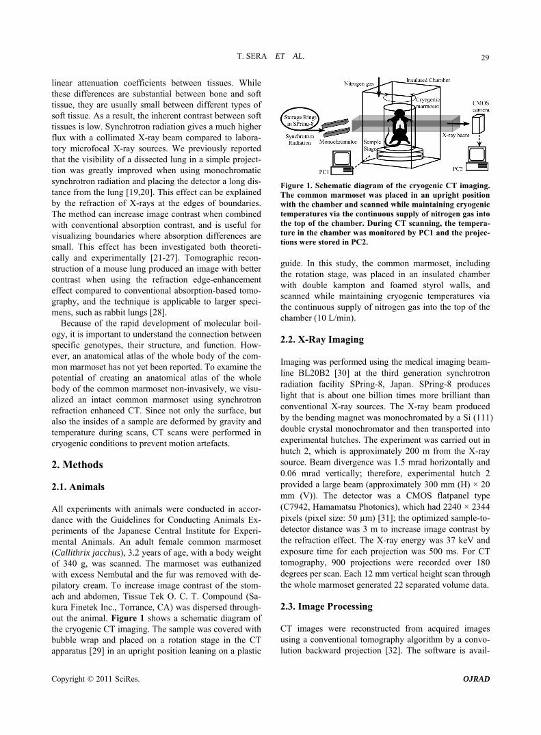
Because of the rapid development of molecular boil- ogy, it is important to understand the connection between specific genotypes, their structure, and function. How- ever, an anatomical atlas of the whole body of the com- mon marmoset has not yet been reported. To examine the potential of creating an anatomical atlas of the whole body of the common marmoset non-invasively, we visu- alized an intact common marmoset using synchrotron refraction enhanced CT. Since not only the surface, but also the insides of a sample are deformed by gravity and temperature during scans, CT scans were performed in cryogenic conditions to prevent motion artefacts. 2. Methods 2.1. Animals All experiments with animals were conducted in accor- dance with the Guidelines for Conducting Animals Ex- periments of the Japanese Central Institute for Experi- mental Animals. An adult female common marmoset (Callithrix jacchus), 3.2 years of age, with a body weight of 340 g, was scanned. The marmoset was euthanized with excess Nembutal and the fur was removed with de- pilatory cream. To increase image contrast of the stom- ach and abdomen, Tissue Tek O. C. T. Compound (Sa- kura Finetek Inc., Torrance, CA) was dispersed through- out the animal. Figure 1 shows a schematic diagram of the cryogenic CT imaging. The sample was covered with bubble wrap and placed on a rotation stage in the CT apparatus [29] in an upright position leaning on a plastic
Figure 1. Schematic diagram of the cryogenic CT imaging. The common marmoset was placed in an upright position with the chamber and scanned while maintaining cryogenic temperatures via the continuous supply of nitrogen gas into the top of the chamber. During CT scanning, the tempera- ture in the chamber was monitored by PC1 and the projec- tions were stored in PC2.
guide. In this study, the common marmoset, including the rotation stage, was placed in an insulated chamber with double kampton and foamed styrol walls, and scanned while maintaining cryogenic temperatures via the continuous supply of nitrogen gas into the top of the chamber (10 L/min). 2.2. X-Ray Imaging Imaging was performed using the medical imaging beam- line BL20B2 [30] at the third generation synchrotron radiation facility SPring-8, Japan. SPring-8 produces light that is about one billion times more brilliant than conventional X-ray sources. The X-ray beam produced by the bending magnet was monochromated by a Si (111) double crystal monochromator and then transported into experimental hutches. The experiment was carried out in hutch 2, which is approximately 200 m from the X-ray source. Beam divergence was 1.5 mrad horizontally and 0.06 mrad vertically; therefore, experimental hutch 2 provided a large beam (approximately 300 mm (H) × 20 mm (V)). The detector was a CMOS flatpanel type (C7942, Hamamatsu Photonics), which had 2240 × 2344 pixels (pixel size: 50 µm) [31]; the optimized sample-to- detector distance was 3 m to increase image contrast by the refraction effect. The X-ray energy was 37 keV and exposure time for each projection was 500 ms. For CT tomography, 900 projections were recorded over 180 degrees per scan. Each 12 mm vertical height scan through the whole marmoset generated 22 separated volume data. 2.3. Image Processing CT images were reconstructed from acquired images using a conventional tomography algorithm by a convo- lution backward projection [32]. The software is avail-

T. SERA ET AL.
Copyright © 2011 SciRes. OJRAD
30
able from http://www-bl20.spring8.or.jp/. Three-dimen- sional reconstruction and visualization of the imaged volumes were performed with the commercial software Amira (Visage Imaging, Inc. USA). 3. Results Synchrotron refraction enhanced CT revealed details of the entire body of the common marmoset non-invasively and clearly. Figure 2 shows representative sagittal and coronal views, and the optimized volume rendering of bones of the whole body. During the entire scan, the temperatures at the top and bottom of the sample chamber were –15˚C and –26˚C, respectively. Therefore, the sam- ple was sufficiently frozen to prevent motion artefacts despite the long scan duration. In this paper, we show images of organs of interest, in particular the abdomen, thorax, and brain of the common marmoset.
Figure 3 shows axial and sagittal views of the common marmoset’s knee. The trabecular structure is clearly visi- ble. Several sections of distal femurs of female marmo- sets are imaged using micro-CT with a resolution of 8 - 16 μm to evaluate their suitability as an osteoporosis model [33]. Pixel size in the previous study was smaller than in this study because it was an ex vivo study and had a small sample size; however, the X-ray beam was white, not monochromatic. White beams can cause beam
hardening effects; otherwise, monochromatic tomogra- phic reconstruction produces a linear attenuation coeffi- cient in each pixel in the absolute scale. Additionally, the in situ synchrotron enhanced CT allowed us to visualize the articular cartilage, the cruciate ligament, and the extensor digitorum tendon between the femur and the tibia, which have not been identified using conventional radiography.
Figure 4 shows representative axial, coronal, and sa- gittal views of the abdomen. Several organs of the com- mon marmoset, such as the kidneys, intestines, stomach, and liver, were visualized clearly. The branching struc- ture in the liver parenchyma was identified; the peripheral branching was seen clearly down to approximately 200 μm. Additionally, in the kidney parenchyma, the renal vein was slightly visible without contrast agents. It seems that some of these structures were veins because of the presence of junctions with the inferior vena cava. Figures 4(a) and (b), the cancellous bone was identified. Since the contrast of the compound that was dispersed through the animal was higher than that of soft tissue, the junction between the oesophagus and the stomach is visible between the thorax and the liver (Figure 4(d)).
Figure 5 shows volume rendering, axial, and coronal images of the thorax. These images clearly show the pulmonary lobe, branching bronchi, and vessels. Airway cartilage and the oesophagus were also imaged, although
(a) (b) (c)
Figure 2. Representative CT images [(a) sagittal view, (b) coronal view at dotted line in (a)] and optimized volume rendering of bones ((c), bounding box size: 11.17 × 7.17 × 19.05 cm3).

T. SERA ET AL.
Copyright © 2011 SciRes. OJRAD
31
(a)
(b)
Figure 3. Representative CT images of the knee; (a) axial image, (b) sagittal image. The articular cartilage [arrow in (a)], the cruciate ligament [arrow in (b)], and the extensor digitorum tendon [arrow head in (b)] are visible.
the trachea was filled with the compound. Small airways, down to an approximately 400-μm diameter, are indicated by an arrow in Figure 5(a). Structures of the heart, such as the left and right ventricles, the pulmonary artery, and the aorta, were identified (Figure 5(b)).
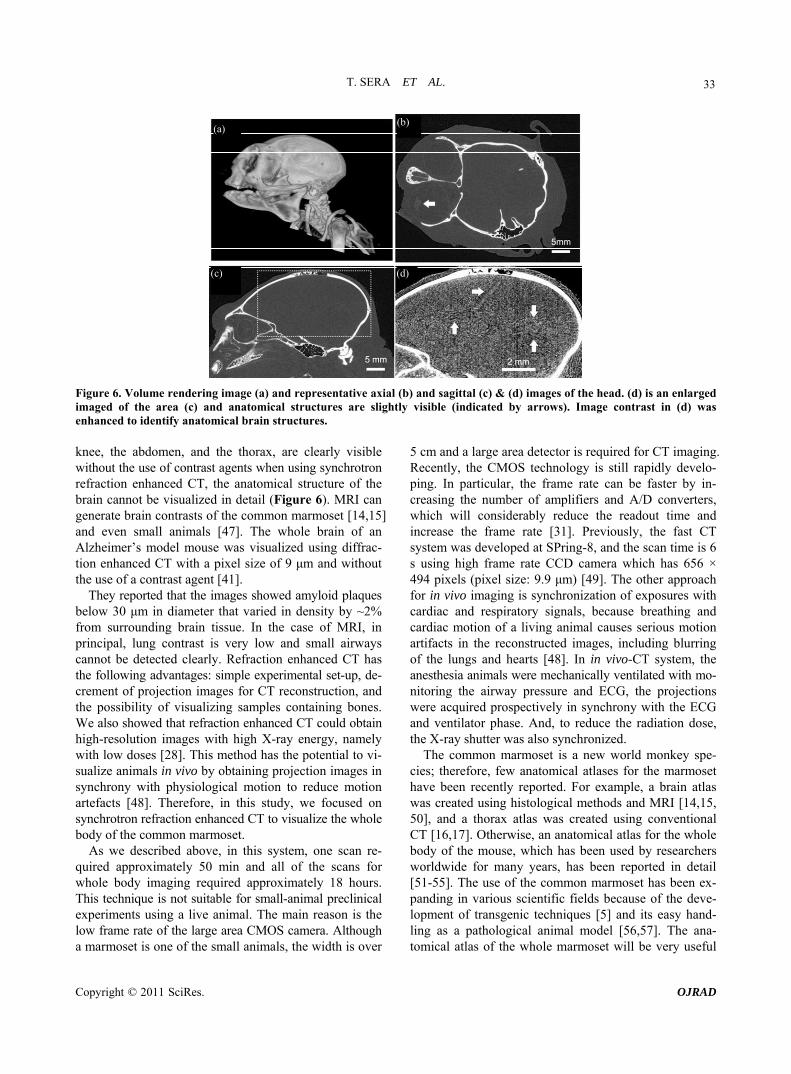
Figure 6 shows volume rendering, axial, and sagittal views of the head. The suture in the skull, the ear space, and the cochlea in the middle ear region were identified. The crystalline lens, the edge of the sclera at the eye, and the anatomical structure of the brain were slightly visible (Figures 6 (c) & (d)). 4. Discussion In this study, we show that refraction enhanced CT can be used to visualize the whole body of an intact common marmoset without the use of contrast agents. Although imaging the whole body of the marmoset required the use of a large voxel size (50 μm), the trabecular structure, articular cartilage, the cruciate ligament in the knee joint, and small airways (diameter > 400 μm) were clearly identified. Branching vessels in the kidneys and liver (diameter > 200 μm), and heart structures, such as the left and right ventricles, the pulmonary artery, and the aorta, were also identified without contrast agents. The high coherence and intensity of the synchrotron X-ray source can increase image contrast through refraction edge enhancement in addition to conventional absorption
contrast. Therefore, boundaries between small absorption differences can be detected without the use of contrast agents.
In refraction enhanced CT, refraction causes artefacts in reconstructed CT images since the reconstruction algorithm assumes that X-rays pass straight through a sample. According to a previous report of airway ima- ging [28], refraction produces a dark line on the inner side (air side) and a bright line on the outer side (tissue side) of air-tissue interfaces. As a result, the pixel inten- sity of air decreases and that of tissues increased, by which image contrast is improved. Although refraction enhanced CT images lack linearity in tissue linear attenu- ation coefficients, refraction seems useful for improving contrast when linear attenuation coefficients are not required. In this study, a cryogenic marmoset was scanned while the chamber was maintained at cryogenic tempera- tures to prevent motion artefacts. In this system, one scan required approximately 50 min; therefore, all of the scans for whole body imaging required approximately 18 hours. In cases where fresh post-mortem marmosets are used soon after euthanasia, sample deformation by rigor mortis during long scans can cause serious motion artefacts. In addition, after rigor mortis, the inside of the body, such as the abdomen, can be deformed by gravity. To keep the marmoset stable during long scans, the sample was placed in an insulated chamber into which nitrogen gas was added continuously. Refraction enhanced imaging, sometimes called “propagation based imaging”, is one of the phase-sensitive methods, such as diffraction enhan- ced imaging (DEI) or “analyser-based imaging,” and interferometric methods. In DEI, an analyser crystal is placed between the sample and the detector, and a transmitted X-ray can be reflected from the analyser crystal within an angular range of a few microradians of the Bragg peak, called the rocking curve. In experiments, DE images are usually created by combining images that are obtained at both the positive and negative sides of the rocking curve with respect to the Bragg peak [34]. Dif- fraction enhanced CT (DECT) has been widely used for mammography [35-37] and imaging joints [38,39], bone [40], and brains [41]. With respect to interferometric me- thods, X-ray Talbot interferometry (XTI) was developed [42]. In XTI, two transmission gratings are placed be- tween the sample and the detector, which are separated by a small distance that causes the Talbot effect by the first grating. The differential phase is measured from the moiré patterns that are imaged behind the second grating. XTI is also used for three-dimensional visualizations of biological samples, such as liver tissues with VX2 cancer [43], kidneys [44], and atherosclerotic arteries [45]. These methods can increase image contrast in addition to the absorption contrast, and the contrast of DEI is greater

T. SERA ET AL.
Copyright © 2011 SciRes. OJRAD
32
(a)
(b)
(c) (d)
Figure 4. Representative axial (a), sagittal (b), and coronal images (c) & (d) of the abdomen. Branching veins in the kidney [arrow in (b)] and liver [arrow in (c)] are identified. The oesophagus is also visible [arrow in (d)].
(a) (b)
Figure 5. Representative axial and coronal images of the thorax. The diameter indicated by the arrow in (a) is approximately 400 μm. The trachea (square), oesophagus (triangle), aorta (arrow), pulmonary artery (arrow head), and left and right ven- tricles (star and diamond) are visible in (b).
than that of refraction enhanced imaging [46]. However, the simple refraction enhanced CT can visualize both soft and hard biological tissues simultaneously, such as the thorax, the abdomen, ligaments, and bones, although
bones can generate severe artefacts in CT images using other methods. Therefore, in this study, we used refrac- tion enhanced CT to visualize an intact whole marmoset.
Although several organs containing bones, such as the
T. SERA ET AL.
Copyright © 2011 SciRes. OJRAD
33
(a) (b)
(c) (d)
Figure 6. Volume rendering image (a) and representative axial (b) and sagittal (c) & (d) images of the head. (d) is an enlarged imaged of the area (c) and anatomical structures are slightly visible (indicated by arrows). Image contrast in (d) was enhanced to identify anatomical brain structures.
knee, the abdomen, and the thorax, are clearly visible without the use of contrast agents when using synchrotron refraction enhanced CT, the anatomical structure of the brain cannot be visualized in detail (Figure 6). MRI can generate brain contrasts of the common marmoset [14,15] and even small animals [47]. The whole brain of an Alzheimer’s model mouse was visualized using diffrac- tion enhanced CT with a pixel size of 9 μm and without the use of a contrast agent [41].
They reported that the images showed amyloid plaques below 30 μm in diameter that varied in density by ~2% from surrounding brain tissue. In the case of MRI, in principal, lung contrast is very low and small airways cannot be detected clearly. Refraction enhanced CT has the following advantages: simple experimental set-up, de- crement of projection images for CT reconstruction, and the possibility of visualizing samples containing bones. We also showed that refraction enhanced CT could obtain high-resolution images with high X-ray energy, namely with low doses [28]. This method has the potential to vi- sualize animals in vivo by obtaining projection images in synchrony with physiological motion to reduce motion artefacts [48]. Therefore, in this study, we focused on synchrotron refraction enhanced CT to visualize the whole body of the common marmoset.
As we described above, in this system, one scan re- quired approximately 50 min and all of the scans for whole body imaging required approximately 18 hours. This technique is not suitable for small-animal preclinical experiments using a live animal. The main reason is the low frame rate of the large area CMOS camera. Although a marmoset is one of the small animals, the width is over
5 cm and a large area detector is required for CT imaging. Recently, the CMOS technology is still rapidly develo- ping. In particular, the frame rate can be faster by in- creasing the number of amplifiers and A/D converters, which will considerably reduce the readout time and increase the frame rate [31]. Previously, the fast CT system was developed at SPring-8, and the scan time is 6 s using high frame rate CCD camera which has 656 × 494 pixels (pixel size: 9.9 μm) [49]. The other approach for in vivo imaging is synchronization of exposures with cardiac and respiratory signals, because breathing and cardiac motion of a living animal causes serious motion artifacts in the reconstructed images, including blurring of the lungs and hearts [48]. In in vivo-CT system, the anesthesia animals were mechanically ventilated with mo- nitoring the airway pressure and ECG, the projections were acquired prospectively in synchrony with the ECG and ventilator phase. And, to reduce the radiation dose, the X-ray shutter was also synchronized.
The common marmoset is a new world monkey spe- cies; therefore, few anatomical atlases for the marmoset have been recently reported. For example, a brain atlas was created using histological methods and MRI [14,15, 50], and a thorax atlas was created using conventional CT [16,17]. Otherwise, an anatomical atlas for the whole body of the mouse, which has been used by researchers worldwide for many years, has been reported in detail [51-55]. The use of the common marmoset has been ex- panding in various scientific fields because of the deve- lopment of transgenic techniques [5] and its easy hand- ling as a pathological animal model [56,57]. The ana- tomical atlas of the whole marmoset will be very useful

T. SERA ET AL.
Copyright © 2011 SciRes. OJRAD
34
for understanding connections between specific genotypes, their structure, and function. 5. Conclusions We have shown that refraction enhanced CT can be used to obtain a whole body atlas of an intact common mar- moset. This method improves the contrast of boundaries between small absorption differences by refraction in addition to conventional absorption. As a result, the tra- becular structure, articular cartilage, ligaments, and small airways were clearly identified with a 50 μm voxel size and 37 keV X-ray energy. Heart structures and branching vessels in the kidneys and liver were visible without the use of contrast agents, and the anatomical structure of the brain can be somewhat identified. MRI is widely used to obtain brain anatomy because of its high soft-tissue con- trast, and the cryosectioning method is also useful for obtaining anatomical data invasively [58,59]. In the fu- ture, we will combine coregistered refraction enhanced CT, MRI, and cryosection data to construct a complete three-dimensional atlas of the whole body of the com- mon marmoset. 6. Acknowledgements These experiments were performed under the approval of the SPring-8 Proposal Review Committee (2010B1313). This work was supported by grants from the Highly Creative Animal Model Development for Brain Sciences, carried out under the Strategic Research Program for Brain Sciences, the Ministry of Education, Culture, Sports, Science and Technology (MEXT) Japan, and from the Funding Program for World-leading Innovative R&D on Science and Technology (FIRST), JSPS. 7. References [1] P. Cagni, I. Gonçalves Jr., F. Ziller, N. Emile and M.
Barros, “Humans and Natural Predators Induce Different Fear/Anxiety Reactions and Response Pattern to Diaze- pam in Marmoset Monkeys,” Pharmacology Biochemis- try and Behavior, Vol. 93, No. 2, 2009, pp. 134-140. doi:10.1016/j.pbb.2009.04.020
[2] A. Iwanami, J. Yamane, H. Katoh, M. Nakamura, S. Mo- moshima, H. Ishii, Y. Tanioka, N. Tamaoki, T. Nomura, Y. Toyama and H. Okano, “Establishment of Graded Spinal Cord Injury Model in a Nonhuman Primate: The Common Marmoset,” Journal of Neuroscience Research, Vol. 80, No. 2, 2005, pp. 172-181. doi:10.1002/jnr.20435
[3] E. Sasaki, K. Hanazawa, R. Kurita, A. Akatsuka, T. Yo- shizaki, H. Ishii, Y. Tanioka, Y. Ohnishi, H. Suemizu, A. Sugawara, N. Tamaoki, K. Izawa, Y. Nakazaki, H. Ha- mada, H. Suemori, S. Asano, N. Nakatsuji, H. Okano and
K. Tani, “Establishment of Novel Embryonic Stem Cell Lines Derived from the Common Marmoset (Callithrix jacchus),” Stem Cells, Vol. 23, No. 9, 2005, pp. 1304- 1313. doi:10.1634/stemcells.2004-0366
[4] M. Raveendran, S. Tardif, C. N. Ross, S. N. Austad, R. A. Harris, A. Milosavljevic and J. Rogers, “Polymorphic Mi- crosatellite Loci for the Common Marmoset (Callithrix jacchus) Designed Using a Cost- and Time-Efficient Me- thod,” American Journal of Primatology, Vol. 70, No. 9, 2008, pp. 906-910. doi:10.1002/ajp.20581
[5] E. Sasaki, H. Suemizu, A. Shimada, K. Hanazawa, R. Oiwa, M. Kamioka, I. Tomioka, Y. Sotomaru, R. Hira- kawa, T. Eto, S. Shiozawa, T. Maeda, M. Ito, R. Ito, C. Kito, C. Yagihashi, K. Kawai, H. Miyoshi, Y. Tanioka, N. Tamaoki, S. Habu, H. Okano and T. Nomura, “Genera- tion of Transgenic Non-Human Primates with Germline Transmission,” Nature, Vol. 459, No. 7246, 2009, pp. 523- 527. doi:10.1038/nature08090
[6] G. Schatten and S. Mitalipov, “Developmental Biology: Transgenic Primate Offspring,” Nature, Vol. 459, No. 7246, 2009, pp. 515-516. doi:10.1038/459515a
[7] G. J. Chellman, J. L. Bussiere, N. Makori, P. L. Martin, Y. Ooshima and G. F. Weinbauer, “Developmental and Re- productive Toxicology Studies in Nonhuman Primates,” Birth Defects Research Part B: Developmental and Re- productive Toxicology, Vol. 86, No. 6, 2009, pp. 446-462. doi:10.1002/bdrb.20216
[8] D. Haig, “What Is a Marmoset?” American Journal of Primatology, Vol. 49, No. 4, 1999, pp. 285-296. doi:10.1002/(SICI)1098-2345(199912)49:4<285::AID-AJP1>3.3.CO;2-O
[9] W. Saltzman and D. H. Abbott, “Effects of Elevated Cir-culating Cortisol Concentrations on Maternal Behavior in Common Marmoset Monkeys (Callithrix jacchus),” Psy- choneuroendocrinology, Vol. 34, No. 8, 2009, pp. 1222- 1234. doi:10.1016/j.psyneuen.2009.03.012
[10] M. A. Hook and L. J. Rogers, “Visuospatial Reaching Pre- ferences of Common Marmosets (Callithrix jacchus): An Assessment of Individual Biases across a Variety of Tasks,” Journal of Comparative Psychology, Vol. 22, No. 1, 2008, pp. 41-51. doi:10.1037/0735-7036.122.1.41
[11] E. Clara, L. Tommasi and L. J. Rogers, “Social Mobbing Calls in Common Marmosets (Callithrix jacchus): Effects of Experience and Associated Cortisol Levels,” Animal Cognition, Vol. 11, No. 2, 2008, pp. 349-358. doi:10.1007/s10071-007-0125-0
[12] S. R. Zahed, S. L. Prudom, C. T. Snowdon and T. E. Ziegler, “Male Parenting and Response to Infant Stimuli in the Common Marmoset (Callithrix jacchus),” Ameri-can Journal of Primatology, Vol. 70, No. 1, 2008, pp. 84- 92. doi:10.1002/ajp.20460
[13] G. Epple, “Comparative Studies on Vocalization in Marmoset Monkeys (Haplidae),” Folia Primatologica (Basel), Vol. 8, No. 1, 1968, pp. 1-40.
[14] J. D. Newman, W. M. Kenkel, E. C. Aronoff, N. A. Bock, M. R. Zametkin and A. C. Silva, “A Combined Histo- logical and MRI Brain Atlas of the Common Marmoset
T. SERA ET AL.
Copyright © 2011 SciRes. OJRAD
35
Monkey, Callithrix jacchus,” Brain Research Reviews, Vol. 62, No. 1, 2009, pp. 1-18. doi:10.1016/j.brainresrev.2009.09.001
[15] K. Hikishima, M. M. Quallo, Y. Komaki, M. Yamada, K. Kawai, S. Momoshima, H. J. Okano, E. Sasaki, N. Ta- maoki, R. N. Lemon, A. Iriki and H. Okano, “Population- Averaged Standard Template Brain Atlas for the Com- mon Marmoset (Callithrix jacchus),” Neuroimage, Vol. 54, No. 4, 2011, pp. 2741-2749. doi:10.1016/j.neuroimage.2010.10.061
[16] T. D. Nishimura, M. Takai, T. Tsubamoto, N. Egi and N. Shigehara, “Variation in Maxillary Sinus Anatomy among Platyrrhine Monkeys,” Journal of Human Evolution, Vol. 49, No. 3, 2005, pp. 370-389. doi:10.1016/j.jhevol.2005.05.001
[17] W. M. Wagner and R. M. Kirberger, “Radiographic Ana- tomy of the Thorax and Abdomen of the Common Mar- moset (Callithrix jacchus),” Veterinary Radiology & Ul- trasound, Vol. 46, No. 3, 2005, pp. 217-224. doi:10.1111/j.1740-8261.2005.00044.x
[18] M. I. Hofmann, C. Schradin and T. Geissmann, “Radio- graphic Evaluation of Neonatal Skeletal Development in Callimico Goeldii Reveals Closer Similarity to Callithrix jacchus than to Saguinus oedipus,” American Journal of Primatology, Vol. 69, No. 4, 2007, pp. 420-433. doi:10.1002/ajp.20361
[19] N. Yagi, Y. Suzuki, K. Umetani, Y. Kohmura and K. Ya- masaki, “Refraction-Enhanced X-Ray Imaging of Mouse Lung Using Synchrotron Radiation Source,” Medical Phy- sics, Vol. 26, No. 10, 1999, pp. 2190-2193. doi:10.1118/1.598735
[20] Y. Suzuki, N. Yagi and K. Uesugi, “X-Ray Refraction- Enhanced Imaging and a Method for Phase Retrieval for a Simple Object,” Journal of Synchrotron Radiation, Vol. 9, No. 3, 2002, pp. 160-165. doi:10.1118/1.598735
[21] A. Snigirev, I. Snigireva, V. Kohn, S. Kuznetsov and I. Schelokov, “On the Possibilities of X-Ray Phase Contrast Microimaging by Coherent High-Energy Synchrotron Ra- diation,” Review of Scientific Instruments, Vol. 66, No. 12, 1999, pp. 5486-5492. doi:10.1063/1.1146073
[22] P. Cloetens, R. Barrett, J. Baruchel, J. Guigay and M. Schlenker, “Phase Objects in Synchrotron Radiation Hard X-Ray Imaging,” Journal of Physics D: Applied Physics, Vol. 29, No. 1, 1997, pp. 133-146. doi:10.1088/0022-3727/29/1/023
[23] S. W. Wilkins, T. E. Gureyev, D. Gao, A. Pogany and A. W. Stevenson, “Phase-Contrast Imaging Using Polychro- matic HARD X-Rays,” Nature, Vol. 384, No. 6607, 1996, pp. 335-338. doi:10.1038/384335a0
[24] R. A. Lewis, C. J. Hall, A. P. Hufton, S. Evans, R. H. Menk, F. Arfelli, L. Rigon, G. Tromba, D. R. Dance, I. O. Ellis, A. Evans, E. Jacobs, S. E. Pinder and K. D. Rogers, “X-Ray Refraction Effects: Application to the Imaging of Biological Tissues,” The British Journal of Radiology, Vol. 76, No. 905, 2003, pp. 301-308. doi:10.1259/bjr/32889803
[25] M. J. Kitchen, R. A. Lewis, N. Yagi, K. Uesugi, D. Pa- ganin, S. B. Hooper, G. Adams, S. Jureczek, J. Singh, C.
R. Christensen, A. P. Hufton, C. J. Hall, K. C. Cheung and K. M. Pavlov, “Phase Contrast X-Ray Imaging of Mice and Rabbit Lungs: A Comparative Study,” The British Journal of Radiology, Vol. 78, No. 935, 2005, pp. 1018- 1027. doi:10.1259/bjr/13024611
[26] D. W. Parsons, K. Morgan, M. Donnelley, A. Fouras, J. Crosbie, I. Williams, R. C. Boucher, K. Uesugi, N. Yagi and K. K. Siu, “High-Resolution Visualization of Air- space Structures in Intact Mice via Synchrotron Phase- Contrast X-Ray Imaging (PCXI),” Journal of Anatomy, Vol. 213, No. 2, 2008, pp. 217-227. doi:10.1111/j.1469-7580.2008.00950.x
[27] M. Donnelley, K. S. Morgan, A. Fouras, W. Skinner, K. Uesugi, N. Yagi, K. K. Siu and D. W. Parsons, “Real- Time Non-Invasive Detection of Inhalable Particulates De- livered into Live Mouse Airways,” Journal of Synchro- tron Radiation, Vol. 16, Part 4, 2009, pp. 553-561. doi:10.1107/S0909049509012618
[28] T. Sera, K. Uesugi, N. Yagi, “Refraction-Enhanced To- mography of Mouse and Rabbit Lungs,” Medical Physics, Vol. 32, No. 9, 2005, pp. 2787-2792. doi:10.1118/1.2008429
[29] K. Uesugi, A. Tsuchiyama, T. Nakano, Y. Suzuki, N. Yagi, K. Umetani and Y. Kohmura, “Development of Mi- cro-Tomography Imaging System for Rock and Mineral Samples,” Proceedings of SPIE 3772, Denver, 22 July 1999, pp 214-221.
[30] S. Goto, K. Takeshita, Y. Suzuki, H. Ohashi, Y. Asano, H. Kimura, T. Matsushita, N. Yagi, M. Isshiki, H. Yama- zaki, Y. Yoneda, K. Umetani and T. Ishikawa, “Constru- ction and Commissioning of a 215-m-Long Beamline at SPring-8,” Nuclear Instruments and Methods in Physics Research Section A, Vol. 467-468, Part. 1, 2001, pp. 682- 685. doi:10.1016/S0168-9002(01)00445-4
[31] N. Yagi, M. Yamamoto, K. Uesugi and K. Inoue, “A Large-Area CMOS Imager as an X-Ray Detector for Syn- chrotron Radiation Experiments,” Journal of Synchrotron Radiation, Vol. 11, Part 4, 2004, pp. 347-352. doi:10.1107/S0909049504008519
[32] A. C. Kak and M. Slaney, “Principles of Computerized Tomographic Imaging,” IEEE Press, New York, 1988.
[33] C. M. Bagi, M. Volberg, M. Moalli, V. Shen, E. Olson, N. Hanson, E. Berryman and C. J. Andresen, “Age-Related Changes in Marmoset Trabecular and Cortical Bone and Response to Alendronate Therapy Resemble Human Bone Physiology and Architecture,” Anatomical Record (Ho- boken), Vol. 290, No. 8, 2007, pp. 1005-1016. doi:10.1002/ar.20561
[34] D. Chapman, W. Thomlinson, R. E. Johnston, D. Wa- shburn, E. Pisano, N. Gmür, Z. Zhong, R. Menk, F. Ar-felli and D. Sayers, “Diffraction Enhanced X-Ray Imag-ing,” Physics in Medicine and Biology, Vol. 42, No. 11, 1997, pp. 2015-2025. doi:10.1088/0031-9155/42/11/001
[35] S. Fiedler, A. Bravin, J. Keyriläinen, M. Fernández, P. Suortti, W. Thomlinson, M. Tenhunen, P. Virkkunen and M. Karjalainen-Lindsberg, “Imaging Lobular Breast Car-cinoma: Comparison of Synchrotron Radiation DEI-CT Technique with Clinical CT, Mammography and Histol-

T. SERA ET AL.
Copyright © 2011 SciRes. OJRAD
36
ogy,” Physics in Medicine and Biology, Vol. 49, No. 2, 2004, pp. 175-188. doi:10.1088/0031-9155/49/2/001
[36] A. Bravin, J. Keyriläinen, M. Fernández, S. Fiedler, C. Nemoz, M. L. Karjalainen-Lindsberg, M. Tenhunen, P. Virkkunen, M. Leidenius, K. von Smitten, P. Sipilä and P. Suortti, “High-Resolution CT by Diffraction-Enhanced X-Ray Imaging: Mapping of Breast Tissue Samples and Comparison with Their Histo-Pathology,” Physics in Me- dicine and Biology, Vol. 52, No. 8, 2007, pp. 2197- 2211. doi:10.1088/0031-9155/52/8/011
[37] J. Keyriläinen, M. Fernández, M. L. Karjalainen-Lind- sberg, P. Virkkunen, M. Leidenius, K. von Smitten, P. Si- pilä, S. Fiedler, H. Suhonen, P. Suortti and A. Bravin, “Toward High-Contrast Breast CT at Low Radiation Dose.” Radiology, Vol. 249, No. 1, 2008, pp. 321-327. doi:10.1148/radiol.2491072129
[38] J. Li, Z. Zhong, D. Connor, J. Mollenhauer, C. Muehle- man, “Phase-Sensitive X-Ray Imaging of Synovial joints,” Osteoarthritis and Cartilage, Vol. 17, No. 9, 2009, pp. 1193-1196. doi:10.1016/j.joca.2009.03.005
[39] P. Coan, A. Wagner, A. Bravin, P. C. Diemoz, J. Key- riläinen and J. Mollenhauer, “In Vivo X-Ray Phase Con- trast Analyzer-Based Imaging for Longitudinal Osteo- arthritis Studies in Guinea Pigs,” Physics in Medicine and Biology, Vol. 55, No. 24, 2010, pp. 7649-7662. doi:10.1088/0031-9155/55/24/017
[40] D. M. Connor, H. D. Hallen, D. S. Lalush, D. R. Sumner and Z. Zhong, “Comparison of Diffraction-Enhanced Com- puted Tomography and Monochromatic Synchrotron Ra-diation Computed Tomography of Human Trabecular Bone,” Physics in Medicine and Biology, Vol. 54, No. 20, 2009, pp. 6123-6133. doi:10.1088/0031-9155/54/20/006
[41] D. M. Connor, H. Benveniste, F. A. Dilmanian, M. F. Krit- zer, L. M Miller and Zhong Z, “Computed Tomography of Amyloid Plaques in a mouse Model of Alzheimer’s Disease Using Diffraction Enhanced Imaging,” Neuroi-mage, Vol. 46, No. 4, 2009, pp. 908-914. doi:10.1016/j.neuroimage.2009.03.019
[42] A. Momose, S. Kawamoto, I. Koyama, Y. Hamaishi, K. Takai, K. Uesughi and Y. Suzuki, “Demonstration of X- Ray Talbot Interferometry,” Japanese Journal of Applied Physics, Vol. 42, Part 2, 2003, pp. L866-L868. doi:10.1143/JJAP.42.L866
[43] A. Momose, W. Yashiro, Y. Takeda, Y. Suzuki and T. Hattori, “Phase Tomography by X-Ray Talbot Interfer- ometry for Biological Imaging,” Japanese Journal of Ap- plied Physics, Vol. 45, No. 6A, 2006, pp. 5254-5262. doi:10.1143/JJAP.45.5254
[44] J. Wu, T. Takeda, T. T. Lwin, A. Momose, N. Sunaguchi, T. Fukami, T. Yuasa and T. Akatsukaka, “Imaging Renal Structures by X-Ray Phase-Contrast Microtomography,” Kidney International, Vol. 75, No. 9, 2009, pp. 945-951. doi:10.1038/ki.2009.42
[45] M. Shinohara, T. Yamashita, H. Tawa, M. Takeda, N. Sa- saki, T. Takaya, R. Toh, A. Takeuchi, T. Ohigashi, K. Shi- nohara, S. Kawashima, M. Yokoyama, K. Hirata and A. Momose, “Atherosclerotic Plaque Imaging Using Phase- Contrast X-Ray Computed Tomography,” American Jour-
nal of Physiology Heart and Circulatory Physiology, Vol. 294, No. 2, 2008, pp. H1094-H1100. doi:10.1152/ajpheart.01149.2007
[46] E. Pagot, S. Fiedler, P. Cloetens, A. Bravin, P. Coan, K. Fezzaa, J. Baruchel, J. Härtwig, K. von Smitten, M. Lei- denius, M. L. Karjalainen-Lindsberg and J. Keyriläinen, “Quantitative Comparison between Two Phase Contrast Techniques: Diffraction Enhanced Imaging and Phase Propagation Imaging,” Physics in Medicine and Biology, Vol. 50, No. 4, 2005, pp. 709-724. doi:10.1088/0031-9155/50/4/010
[47] Y. Ma, P. R. Hof, S. C. Grant, S. J. Blackband, R. Ben- nett, L. Slatest, M. D. McGuigan and H. Benveniste, “A Three-Dimensional Digital Atlas Database of the Adult C57BL/6J Mouse Brain by Magnetic Resonance Micros-copy,” Neuroscience, Vol. 135, No. 4, 2005, pp. 1203- 1215. doi:10.1016/j.neuroscience.2005.07.014
[48] T. Sera, H. Yokota, K. Fujisaki, K. Fukasaku, H. Tachi- bana, K. Uesugi, N. Yagi and R. Himeno, “Development of High-Resolution 4D in Vivo-CT for Visualization of Cardiac and Respiratory Deformations of Small Animals,” Physics in Medicine and Biology, Vol. 53, No. 16, 2008, pp. 4285-4301. doi:10.1088/0031-9155/53/16/005
[49] K. Uesugi, T. Sera and N. Yagi, “Fast Tomography Using Quasi-Monochromatic Undulator Radiation,” Journal of Synchrotron Radiation, Vol. 13, part 5, 2006, pp. 403- 407.doi:10.1107/S0909049506023466
[50] H. Tokuno, I. Tanaka, Y. Umitsu, T. Akazawa and Y. Na- kamura, “Web-Accessible Digital Brain Atlas of the Com- mon Marmoset (Callithrix jacchus),” Neuroscience Re- search, Vol. 64, No. 1, 2009, pp. 128-131. doi:10.1016/j.neures.2009.02.003
[51] M. Dhenain, S. W. Ruffins and R. E. Jacobs, “Three- Dimensional Digital Mouse Atlas Using High-Resolution MRI,” Developmental Biology, Vol. 232, No. 2, 2001, pp. 458-470. doi:10.1006/dbio.2001.0189
[52] G. A. Johnson, G. P. Cofer, S. L. Gewalt and L. W. Hed- lund, “Morphologic Phenotyping with MR Microscopy: The Visible Mouse,” Radiology, Vol. 222, No. 3, 2002, pp. 789-793. doi:10.1148/radiol.2223010531
[53] W. P. Segars, B. M. Tsui, E. C. Frey, G. A. Johnson and S. S. Berr, “Development of a 4-D Digital Mouse Phan- tom for Molecular Imaging Research,” Molecular Imag- ing and Biology, Vol. 6, No. 3, 2004, pp. 149-159. doi:10.1016/j.mibio.2004.03.002
[54] B. Dogdas, D. Stout, A. F. Chatziioannou and R. M. Leahy, “Digimouse: A 3D Whole Body Mouse Atlas from CT and Cryosection Data,” Physics in Medicine and Biology, Vol. 52, No. 3, 2007, pp. 577-587. doi:10.1088/0031-9155/52/3/003
[55] M. Baiker, J. Milles, J. Dijkstra, T. D. Henning, A. W. Weber, I. Que, E. L. Kaijzel, C. W. Löwik, J. H. Reiber and B. P. Lelieveldt, “Atlas-Based Whole-Body Segmen- tation of Mice from Low-Contrast Micro-CT Data,” Me- dical Image Analysis, Vol. 14, No. 6, 2010, pp. 723-737. doi:10.1016/j.media.2010.04.008
[56] E. Bihel, P. Pro-Sistiaga, A. Letourneur, J. Toutain, R. Saulnier, R. Insausti, M. Bernaudin, S. Roussel and O.

T. SERA ET AL.
Copyright © 2011 SciRes. OJRAD
37
Touzani, “Permanent or Transient Chronic Ischemic Stroke in the Non-Human Primate: Behavioral, Neuroimaging, Histological, and Immunohistochemical Investigations,” Journal of Cerebral Blood Flow & Metabolism, Vol. 30, No. 2, 2009, pp. 273-285. doi:10.1038/jcbfm.2009.209
[57] A. Iwanami, S. Kaneko, M. Nakamura, Y. Kanemura, H. Mori, S. Kobayashi, M. Yamasaki, S. Momoshima, H. Ishii, K. Ando, Y. Tanioka, N. Tamaoki, T. Nomura, Y. Toya- ma and H. Okano, “Transplantation of Human Neural Stem Cells for Spinal Cord Injury in Primates,” Journal of Neuroscience Research, Vol. 80, No. 2, 2005, pp. 182- 190. doi:10.1002/jnr.20436
[58] H. Yokota, R. Kawaguchi, S. Nakamura, A. Makinouchi, T. Higuchi and H. Yabe, “3-Dimensional Digitizing for the Biological Sample Using a 3-Dimensional Internal Structure Microscope,” 2001 Proceedings of the Bioen- gineering Conference ASME, Snowbird, Utah, 27 June-1 July 2001, pp. 217-218.
[59] H. Yokota, K. Kudoh, T. Higuchi, Y. Sagara and G. S, Do, “Observation and Measurement of Frozen Biological Sample by 3-Dimensional Internal Structure Microscope,” Cryobiology and Cryotechnology, Vol. 44, No. 1, 1998, pp. 1-9.