Embed Size (px)
Citation preview

STUDY REPORT
"SURVEY AND DESIGN OF SIMPLE SPAN PRECAST CONCRETE
GIRDERS MADE CONTINUOUS"
C. C. Fu, Ph.D., P.E. and T. Kudsi
The Bridge Engineering Software and Technology (BEST) Center
Department of Civil and Environmental Engineering
University of Maryland
September, 2000
Table of Contents
INTRODUCTION 1
SURVEY & COMMENTARY 3
Design Of Diaphragm Over Pier Of Precast Beams (Spreadsheet) 10
AASHTO –Girders Analysis, Typical (Spreadsheet Analysis) 11
Bulb-Tee Girders Analysis, Typical (Spreadsheet Analysis) 12
APPENDIX 13

STUDY REPORT
"SURVEY AND DESIGN OF SIMPLE SPAN PRECAST CONCRETE GIRDERS
MADE CONTINUOUS"
Introduction
The objective of this study for the State of Maryland is to provide a standard
detail for making simple span pre-cast concrete girders continuous for live load.
The use of prestressed pre-cast girders in bridge construction started in the United
States in the early 1950’s. Although the girders were designed as simple span for dead
load, reinforcement in the deck girders provided negative moment capacity. Recently,
the demand in the State of Maryland for making simple span precast girders continuous
over pier has increased, thus a standard detail for diaphragms over piers, showing the
necessary reinforcements for different span lengths is needed.
The study started by sending letters to the Departments of Transportation in all 50
states requesting their standard detail drawings of diaphragms over piers. Twenty-seven
states replied, sending their various approaches to continuity over piers. Although some
states did not make simple spans continuous, many states made the deck longitudinal
reinforcement resist the negative moment, and some stipulated that the diaphragm over
pier resist the negative moment due to live load. In addition to designing for negative
moment over pier, many states designed for positive moment at the supports resulting
from creep, shrinkage and elastic shortening. The latter subject will be discussed in the
section titled: ”Survey and Commentary.”

Next, a spreadsheet was prepared for all the types of AASHTO and Bulb-Tee
girders with different span lengths that were cited by the states’ replies. The spreadsheet
calculates the required reinforcement for negative moment, and positive moment for the
types of girders and span lengths that are listed. It should be noted that positive moment
in the diaphragm is usually a result of creep and shrinkage.
Many reports have discussed this issue. NCHRPR 322, ”Design of Precast Bridge
Girders Made Continuous,” concluded that positive moment connections are costly and
provide no structural benefits. On the other hand, an interim report prepared for the
National Cooperative Highway Research Program (NCHRP) Project 12-53 (1999),
“Connection between Simple Span Precast Concrete Girders Made Continuous,”
discusses the importance of accounting for positive moment resulting from creep and
shrinkage. The author of the 1999 NCHRP Project 12-53 interim report does not give a
closed form solution to standardize the calculation of the positive moment; he states that
current PCA practice does not perform a time dependent analysis, and, instead, details the
positive moment connection using 1.2Mcr.
In the spreadsheet the user is left to use the default 1.2Mcr as positive moment at
the connection, or he can input the calculated time dependent positive moment due to
shrinkage, creep, and elastic shortening.

Survey & Commentary
Letters to fifty states were sent by the BEST Center, asking them to send their
standard details for diaphragm over pier. Twenty-eight states replied to our request.
Appendix A shows a brief description for every state’s practice for continuity over pier.
The states that replied are categorized as follows:
A. States using diaphragm over pier to resist live load and superimposed dead load, and
using extended dowels or strands into the diaphragm to resist positive moments:
1. Alaska
2. Colorado
3. Delaware
4. Idaho
5. Illinois
6. Kansas
7. Michigan
8. Missouri
9. New Jersey
10. North Carolina
11. Ohio
12. Oregon
13. Pennsylvania
14. New York

B. States using diaphragm over pier without positive moment reinforcement shown:
1. Kentucky
2. Louisiana
3. North Dakota
4. Tennessee
5. Utah
6. Virginia
7. Wisconsin
8. Wyoming
9. California
C. States using deck slab to assess for continuity:
1. Georgia
2. Minnesota
D. States having no standards for continuity or not designing for continuity over pier for
live load:
1. Maine
2. Massachusetts
3. Washington

In categories A and B where the mentioned states assess for continuity over pier
by using a diaphragm, the states in category B do not show clearly the assessment for the
positive moment resulting from time dependent losses in the precast girders. Two reports
were reviewed, addressing the subject of assessing for positive moment over pier
resulting from creep, shrinkage, and elastic shortening.
In reference to Appendix G of the NCHRP report 322, “Design Of Precast
Prestressed Bridge Girders Made Continuous,” November 1989,
“Results of an analytical study (G-1) of time-dependent restraint moment and service
load moments at supports in prestressed concrete girders made continuous indicate
that there is little structural advantage gained by providing positive moment
reinforcement at supports.”
The report also states that the creep and shrinkage will produce
“A positive restraint moment at the supports that will generally induce a crack in the
bottom of the diaphragm concrete. With application of live load, the positive moment
crack must close prior to inducing negative moment at the continuity connection.
There is a loss of negative continuity moment associated with the closing of cracks in
the bottom of the diaphragm. The presence of positive moment reinforcement in the
diaphragm helps to maintain a relatively small crack, thereby increasing apparent live
load. However, the positive restraint moment resulting from the presence of the
reinforcement in the bottom of the diaphragm increases the positive moment within
the span. This increase in positive moment when bottom reinforcement is used at
supports is virtually equal to the loss of negative moment continuity if positive
reinforcement is not used. The net result on the effective continuity moment is the
same, irrespective of whether or not positive moment reinforcement is provided at
supports. Therefore, providing positive moment reinforcement has no significant
benefit for reducing service load moments.”
NCHRPR 322 proposes that the commentary should be added to section 9.7.2.2 of the
Standard Specification (AASHTO).
It should be noted that Standard Specifications for Highway Bridges, Sixteenth
Edition (1996 with Interims up to 2000) contains the statement for positive moment at
connection at piers (9.7.2.2.1),
” Provision shall be made in the design for the positive moments that may develop in
the negative moment region due to the combined effects of creep and shrinkage in the
girders and deck slab, and due to the effect of live load plus impact load in remote
spans. Shrinkage and Elastic shortening of the pier shall be considered when
significant."
In September 1999, the University of Cincinnati submitted an interim report to the
NCHRP, ”Connection Between Simple Span Precast Concrete Girders Made
Continuous.” (It is important to note that the unpublished report was obtained from
NCHRP and has not yet been released for publication.) The study team's review of the
report content is solely for the purpose of the presented study. The report concluded that
many engineers and state agencies think that positive moment connections are needed to
control cracking in the diaphragm and to provide continuity. The report also revealed
that PCA was first to identify cracking of the connection caused by time dependent
positive moments. In addition, many studies discussed in the report state that the cause
of cracking appears to be positive moment developed from time dependent deformations
of the prestressed girders.
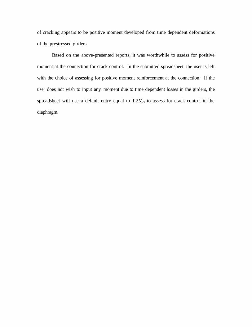
Based on the above-presented reports, it was worthwhile to assess for positive
moment at the connection for crack control. In the submitted spreadsheet, the user is left
with the choice of assessing for positive moment reinforcement at the connection. If the
user does not wish to input any moment due to time dependent losses in the girders, the
spreadsheet will use a default entry equal to 1.2Mcr to assess for crack control in the
diaphragm.

Design and Analysis
A thorough review of standard details continuity over pier from the 28 states,
NCHRP Report 322, and NCHRP Project 12-53 Interim Report prepared by University of
Cincinnati, led to the final design of the standard detail for diaphragm over pier for the
State of Maryland. The PCI bridge design manual was also referred to for the design of
the diaphragm. The AASHTO Standard Specifications for Highway Bridges (Sixteenth
Edition) was used also. Based on the review, a spreadsheet that calculates the positive
moment reinforcement and negative moment reinforcement at a pier was constructed.
The design was based on a concrete rectangular block having a height equal to the
adjacent beams including the slab thickness, and the width was taken equal to the
adjacent beams bottom width. The spreadsheet accounts for all type of AASHTO Girders
and Bulb-Tee Girders. The user has to input the negative dead load moment combination
and live load. Also, the user shall input the positive moment due to the combined effects
of creep and shrinkage in the girder and deck slab, and to the effect of live load plus
impact in remote spans (STD. 9.7.2.2.1). If the user wishes not to input any positive
moment, the spreadsheet will use a default value equal to1.2Mcr to assess for crack
control in the diaphragm. Figure 1 shows the dimensions and reinforcement details of the
proposed diaphragm detail over pier for the State of Maryland. Referring to the
spreadsheet, Bar A is to be found for all types of girders based on the inputted dead load
and live load combinations. Bars B, C, and D are standard for all types of AASHTO and
Bulb-Tee Girders. The user can still change the latter mentioned bars.

Figure 1. Diaphragm Over Pier Detail
In Figure 2, a transverse section of the diaphragm between girders is shown. It
should be noted that horizontal reinforcements are temperature and shrinkage
requirements of ACI and AASHTO. Stirrups calculations were based on minimum
reinforcement as per ACI and AASHTO requirements. The spreadsheet includes a
detailed design and analysis for the girders types listed. A table of different types of
girder dimensions and parameters is included in the report, and a summary table of all the
states which replied is also included.
Figure 2. Transverse Cross-Section of Diaphragm

Design Of Diaphragm Over Pier Of Precast Beams (Spreadsheet)
1. Dimensions of the diaphragm over pier are shown in figure 1.
2. Layout of reinforcement is shown in figures 1 & 2.
3. Design was based on a concrete block with a width equals the girder bottom
flange width and the depth equals the beam height plus the thickness of the slab.
4. The user should enter the dead load combination and live load and impact load
combination in the assigned cells.
5. The user should choose the reinforcement to assess for negative moment over
pier, for any type of girder.
6. The spreadsheet will check the adequacy of the chosen area of reinforcement.
7. The spreadsheet calculates the required reinforcement for positive moment as per
1.2Mcr (by default). The user has the choice to enter a value for positive moment
over pier due to creep and shrinkage and remote spans. The spreadsheet will
calculate the adequacy of the inputted moment for the standard reinforcement.
8. Table 1 (Bar A): Spreadsheet user can input the chosen bar diameter and quantity
(step 1 – 10).
9. Table 2 (Bar B): the table shows the recommended standard for reinforcement for
positive moment. The user can change the standard, and the spreadsheet will
check its adequacy (step 11).
10. Table 3 (Bar C): the table shows the recommended standard for stirrups. The
user can change the standard, and the spreadsheet will check its adequacy (step
12.
11. Table 4 (Bar D): the table shows the recommended standard for temperature and
shrinkage reinforcement. The user can change the standard, and the spreadsheet
will check its adequacy (step 13).

By C. C. Fu & T. Kudsi, 8/7/00
Type I Type II Type III Type IV Type V Type VI
45 50 80 100 120 140 Diaphragm Width 30 in
36.5 44.5 53.5 62.5 71.5 80.5 fy 60000 psi16 18 22 26 28 28 f'c 7000 psi
*Depth = height of Beam + slab Thickness +Haunch - 2.5 Slab Thickness 9 inLoad Input Haunch 2 in
φ φ 0.9
0 0 0 0 0 0 ββ1 0.7
57 70 181 283 408 556 m 10.08261.87 328.5 681.5 934.34 1204.5 1485.4 fr 627.5 psi
* No sign neededNegative Moment Analysis (Bar A)
642.62 804.174 1714.84 2396.35 3145.37 3947.6 AASHTO Girders
401.96 300.81 363.10 314.60 292.98 290.08 Type I 12 # 5 13 # 5
4.05437 4.12284 7.3546 8.75837 10.0291 11.1769 Type II 12 # 5 13 # 5
7.75 7.75 7.75 11.23 11.23 11.23 Type III 12 # 5 13 # 5
1187.76 1476.23 1803.87 3048.38 3511.06 3965.88 Type IV 12 # 7 13 # 5
0.006942 0.005147 0.006249 0.005390 0.005010 0.004959 Type V 12 # 7 13 # 50.030813 0.030813 0.030813 0.030813 0.030813 0.030813 Type VI 12 # 7 13 # 5
229.078 381.203 670.918 1079.23 1518.04 1921.26 * Over the effective width* As(chosen)
- = Additional As(chosen)- + Standard Slab Reinf As
Negative Moment Checks AASHTO Girders
Type I 7 # 6OK OK OK OK OK OK Type II 7 # 6
OK OK OK OK OK OK Type III 7 # 6OK OK OK OK OK OK Type IV 7 # 7
Type V 7 # 8Positive Moment Analysis (Bar B) Type VI 7 # 8
0.00 0.00 0.00 0.00 0.00 0.00
143.29 142.59 142.06 141.68 141.40 141.18 AASHTO Girders
0.00 0.00 0.00 0.00 0.00 0.002382 Type I # 5 @ 12 in c/c closed strirrup1.4119 1.92701 2.82087 3.88407 4.7755 5.36816 Type II # 5 @ 12 in c/c closed strirrup3.08 3.08 3.08 4.2 5.53 5.53 Type III # 5 @ 12 in c/c closed strirrup
* if no value is input, spreadsheet uses a default value of 1.2Mcr Type IV # 5 @ 12 in c/c closed strirrup
Adequacy of Chosen Area Of Steel Type V # 5 @ 12 in c/c closed strirrupType VI # 5 @ 12 in c/c closed strirrup
OK OK OK OK OK OK
OK OK OK OK OK OK
AASHTO Girders
Minimum Pier Diaphragm Reinfocement between Beam (Bars C & D) Type I # 5 @ 12 in c/c /back & FrontType II # 5 @ 12 in c/c /back & Front
0.50 0.50 0.50 0.50 0.50 0.50 Type III # 5 @ 12 in c/c /back & Front
0.62 0.62 0.62 0.62 0.62 0.62 Type IV # 6 @ 12 in c/c /back & Front
OK OK OK OK OK OK Type V # 6 @ 12 in c/c /back & Front0.66 0.66 0.66 0.66 0.66 0.66 Type VI # 6 @ 12 in c/c /back & Front
0.62 0.62 0.62 0.88 0.88 0.88 **Note: Tables for Bars B,C,and D are standards, user can change the recommended NO NO NO OK OK OK reinforcement by inputting in the related cells the desired reinforcement.
The Spreadsheet wwill check the adequacy of the user's choice.
Note: Design of continuity was based on a concrete block having the width of the bottom flange and the height
of the chosen beam and chosen slab thickness
Note: Loading is Based on HS-25
Table 1: Bar A*
As(Stirrups)
Table 3 : **Bar C
As(Temperature&Shrinkage)
Table 4 :**Bar D
Standard Slab Reinf. As
As (Min), Stirrups, Bar C
As(Min, T&S), Bar D
Additional As(chosen)-
As(chosen)+
Aest+>= Achosen
+
φφMn, k-ft
*Mu+, k-ft
ρρ0.75ρρb
1.2Mcr, k-ft
AASHTO Girders
As(chosen)-, in2*
Aest->= As(chosen)
-
As(chosen)+, in2
Rn, psi
ρρAest
+, in2
φφMn > Mu
ρ ρ < 0.75ρρb
φφMn > 1.2Mcr
Rn, psi
Girder width, in
MDL-, k-ft*
MSDL-, k-ft*
MLL+I-, k-ft*
AASHTO Girder Continuity Over Pier Analysis and Design
Adequacy of Bar D
Adequacy of Bar C
Bar C, chosen in2/ft
Bar D, chosen in2/ft
Table 2 : **Bar B
Aest-, in2
Max Span Length, ft
Depth, in *
MU-, k-ft

Negative Moment Analysis
PCI-8.2.3: Design of Negative Moment Regions For Members Made Continous for Live LoadUse the width of the bottom flange as the width of the concrete compressive block, b. Determine the required
steel in the deck to resist the total factored negative Moment, assuming the compression block is uniform
Step 1 Mu = 1.3*(MDL+MSDL+1.67*MLL+I), (7.3.1-3, PCI Bridge Design Manual)
Step 2 Rn =Mu/(φbd2), (8.2.3.1-1, PCI Bridge Design Manual) ,b = width of Selected Girder
Step 3 ρ = (1/m)*(1-sqrt(1-2mRn/fy)), (8.2.3.1-2, PCI Bridge Design Manual)
Step 4 m = fy/(0.85f'c), (8.2.3.1-3, PCI Bridge Design Manual)
Step 5 As = ρbd ,b = width of Selected Girder
Step 6 φMn = φAsfy(d-a/2), (STD Eq. 8-16)
Step 7 a = Asfy/0.85f'cb, (STD Eq. 8-17) ,b = width of Selected Girder
Reinforcment Limits (Standard Specifications)
Step 8 ρb =(0.85β1f'c/fy)*(87,000/(87,000+fy)), (STD Art. 8.16.3.1)
Step 9 ρmax =0.75ρb, (STD Art. 8.16.3.1.1)
Minimum Reinforcement, (STD Art.8.17.1)
the total amount of nonprestressed reinforcement should be adequate to develop an ultimate moment at the crtical section
at least 1.2 times the cracking moment. The cracking moment may be calculated as for a prestressed
concrete section except fpe = 0
Step 10 φMn >= 1.2Mcr
Positive Moment Analysis
Step 11 Mu+ = User should input its value as per STD Art 9.7.2.2.1, if no value is inputed spreadsheet will use
a default value of 1.2Mcr
Minimum Reinforcement For Stirrups Calculations
Step 12 As (Min), Stirrups, Bar C = 0.0316*sqrt(f'c)*bw*s/fy, s = spacing = 12 in, (AASHTO LRFD-5.8.2.5-1)
where fy and f'c in step 12 are in KSI
bw = width of Diaphragm over Pier, in inches
Temperature & Shrinkage Reinforcement Calculations
Step 13 As (Min, T&S), Bar D = 0.0018*bw*h, (ACI 7.12.2.1)
bw = width of diaphragm

BT-54 BT-63 BT-72114 130 146 Diaphragm Width 30 in
62.5 71.5 80.5 fy 60000 psi26 26 26 f'c 7000 psi
*Depth = height of Beam + slab Thickness +Haunch - 2.5 Slab Thickness 9 inLoad Input Haunch 2 in
φ φ 0.9
0 0 0 ββ1 0.7
368.29 479.43 605.2 m 10.0841122.83 1317.82 1590.59 fr 627.495 psi
* No sign neededNegative Moment Analysis (Bar a)
Bulb-Tee Girders
2916.44 3484.25 4239.93 Type I 12 # 7 13 # 5382.88 349.51 335.53 Type II 12 # 7 13 # 510.7266 11.1673 12.0545 Type III 12 # 8 13 # 511.23 11.23 13.51 * Over the effective width
3048.38 3503.20 4734.72
0.006601 0.006007 0.005759 Bulb-Tee Girders
0.030813 0.030813 0.030813 Type I 6 # 5372.251 550.627 792.903 Type II 6 # 5
* As(chosen)- = Additional As(chosen)
- + Standard Slab Reinf As Type III 6 # 6
Negative Moment Checks
OK OK OK Bulb-Tee Girders
OK OK OK Type I # 5 @ 12 in c/c closed strirrupOK OK OK Type II # 5 @ 12 in c/c closed strirrup
Type III # 5 @ 12 in c/c closed strirrup
Positive Moment Analysis (Bar B)
0.00 0.00 0.00 Bulb-Tee Girders
48.87 55.23 62.75 Type I # 8 @ 12 in c/c Back & Front
0.00 0.00 0.00 Type II # 9 @ 12 in c/c Back & Front1.32904 1.71937 2.20049 Type III # 9 @ 12 in c/c Back & Front
1.86 1.86 2.64 **Note: Tables for Bars B,C,and D are standards, user can change the recommended
* if no value is input, spreadsheet uses a default value of 1.2Mcr reinforcement by inputting in the related cells the desired reinforcement.
The Spreadsheet wwill check the adequacy of the user's choice.
Adequacy of Chosen Area Of Steel
OK OK OKOK OK OK
Minimum Pier Diaphragm Reinfocement between Beam (Bars C & D)
0.50 0.50 0.50
0.62 0.62 0.62
OK OK OK0.66 0.66 0.66
7.11 10.50 12.00OK OK OK
Note: Design of continuity was based on a concrete block having the width of the bottom flange and the height
of the chosen beam and chosen slab thickness
Note: Loading is Based on HS-25
0.75ρρb
Aest->= As(chosen)
-
Aest+>= Achosen
+
As(chosen)+, in2
φφMn > Mu
ρ ρ < 0.75ρρb
φφMn > 1.2Mcr
MDL-, k-ft *
MSDL-, k-ft *
MLL+I-, k-ft *
MU-, k-ft
Bulb-Tee GirdersMax Span Length, ft
Depth, in *Girder width, in
Adequacy of Bar D
Table 2 : **Bar BAs(chosen)
+
As(chosen)-
Rn, psi
Aest+, in2
Step 11Mu+, k-ft *
As (Min), Stirrups, Bar C
As(Min, T&S), Bar D
ρρ
Bulb-tee Girder Continuity Over Pier Analysis and Design
Bar C, chosen in2
Adequacy of Bar C
Bar D, chosen in2
ρρ
Aest-, in2
As(chosen)-, in2
φφMn, k-ft
Rn, psi
1.2Mcr, k-ft
Standard Slab Reinf. AsTable 1: Bar A*
Table 4 : **Bar DAs(Temperature&Shrinkage)
Table 3 : **Bar CAs(Stirrups)

Type I Type II Type III Type IV Type V Type VIh, in 28 36 45 54 63 72 Bar # Area DiameterAc, in
2 276 369 560 789 1013 1085 3 0.110 0.375
Ig, in4 22,750 50,979 125,390 260,741 521,180 733,320 4 0.200 0.500Sections c1, in 15.41 20.17 24.73 29.27 31.04 35.62 5 0.310 0.625
c2, in 12.59 15.83 20.27 24.73 31.96 36.38 6 0.440 0.750
r2, in2 82 138 224 330 514 676 7 0.600 0.875Properties wo, plf 288 384 583 822 1055 1130 8 0.790 1.000
Wb, in 16 18 22 26 28 28 9 1.000 1.128Wt, in 12 12 16 20 42 42 10 1.270 1.270hft, in 4 6 7 8 5 5 11 1.560 1.410hfb, in 5 6 7 8 8 8
BT-54 BT-63 BT-72 f'c ββ1
h, in 54 63 72 4000 0.85
Sections Ac, in2 659 713 767 5000 0.80
Ig, in4 268,077 392,638 545,894 6000 0.75
ybottom, in 27.63 32.12 36.6 7000 0.70
Properties wo, plf 686 743 799 8000 0.65
Wb, in 26 26 26Wt, in 42 42 42
Look-up Tables for AASHTO and Bulb-tee Girders
Area of Steel
Bulb Tee Girders
AASHTO Bridge Girders

Appendix

A1 A2 A3 Filler Bearing Type Additional Descriptions Details Dwgs
Continuous. Use as per dwgs, or extend min
4 strands from girder into the diaphragm.
13 mm performed
cork
12 mm, preformed Not Continuous. Deck Slab is Continuous
joint filler over the intermediate Bents.
Premolded joint
filler
Not Continuous.PB provide for LL and DL -ve M.
The +M section of PB is designed for SS only.
No Standards for PB diaphragms, shown are for
bridges built with the NEBT Girders.
Diaphragm keyed into pier, surrounded by closed 25
mm cell foam NEBT.
Not Continuous. Slab designed
to assess for continuity.
Filler Diaphragm keyed into pier 300 mm by a dowel bar
under diaphragm extended the strands into diaphragm for +M
Not Continuous. Slab designed
to assess for continuity.
Laminated
elastomeric pad
Not Continuous. Extended Prestressed strands.
min 300 mm to a max 375 mm into the diaphragm
250 mm (+M)
100 mm (no +M)
Foam under
Diaphragm
Foam under No Standards for PB, shown was used on
Diaphragm individual bridges.
1/2'' Premolded
joint filler
PB assumed SS for DL and continuous for LL.
R/C Diaphragm encasing ends of girder.
ContinuousExtends strands from girder into the diaphragm.
Notes PB = Pre-stressed Beam
A1 = Total Diaphragm Width
A2 = Clear Space between the Two girders
A3 = Space usually filled with cardboard or preformed filled
when Deck is designed to account for continuity
+M = Positive Moment
-M = Negative Moment
SS = Simple Span
NEBT = New England Bulb Tee Beam
"-" = Not Available
Elastomeric pad Continuous
Elastomeric pad600 150 - -
Elastomeric pad
-3'-8''
Diaphragm Dimensions Additional Descrition
Colorado 3'-0'' - - - -
States
Delaware 634 mm 280 mm - -
A1.1
Continuous
A1.3
A1.2
Georgia
Idaho
Kansas
Kentucky
Illinois
Louisiana
Maine
Massachusetts
Michigan
Minnesota
North Carolina
North Dakota
Ohio
New Jersey
Missouri
Oregon
Pennsylvania
Tennessee
Utah
Virginia
Washington
Wisconsin
wyoming
612 mm -
-205 mm-
A1.7
-
-
-
-
Elastomeric pad
-
Continuous
Continuous
-
A1.24
A1.25
A1.8
A1.9
A1.10
A1.13
A1.23
A1.18
A1.19
A1.20
A1.14
A1.12
A1.21
A1.11
joint filler
-
Continuous
A1.22
A1.17
A1.15
A1.16
Continuous
Continuous
Styrofoam
650 mm 300 mm
- -
- -
Neoprene pad -
750 mm -
250 mm -
-
-
-
-
1/2'' joint filler
0'-2'' Polystrene
12 mm cardboard
-
-
Elastomeric pad
Elastomeric pad
-
- 300 mm -
2'-3'' 0'-7''
2'-6'' 0'-10'' - -
1'-0'' -
Elastomeric pad
2'-6''
-
2'-0'' 0'-9'' - -
635 mm 520 mm -
-
750 mm
No Standards for PB diaphragms.
Elastomeric pad600 mm - -
450 mm 150 mm -
900 mm 250 mm -
-
-
-
-
300 mm - -
Elastomeric pad
Continuous
Not official works, but frequently used.
Not Continuous. PB designed as SS for DL and LL.
760 mm
Polystrene
300 mm
-
bearings pads
--1'-0''
2'-0'' -
Not Continuous. Concrete Diaphragm Between PB. A1.4
A1.6
Continuous A1.5
300 mm -
2'-4'' 0'-4''
California
New York State
1'-8'' 0'-3''
-
A1.26
A1.27Continuous-
- Elastomeric pad Continuous
Alaska 600 mm 300 mm -
Table of Survey Summary and Commentary
- - N/A
--250 mm
- Continuous100 mm

Colorado Appendix A1.1

Delaware Appendix A1.2

Georgia Appendix A1.3

Georgia Appendix A1.3.1

Idaho Appendix A1.4

Illinois Appendix A1.5

Illinois Appendix A1.5.1

Illinois Appendix A1.5.2

Kansas Appendix A1.6

Kansas Appendix A1.6.1

Kentucky Appendix A1.7

Kentucky Appendix A1.7.1

Louisiana Appendix A1.8
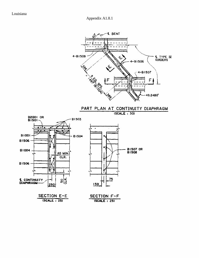
Louisiana Appendix A1.8.1

Maine Appendix A1.9

Massachusetts Appendix A1.10
NEBT Beam Continuity
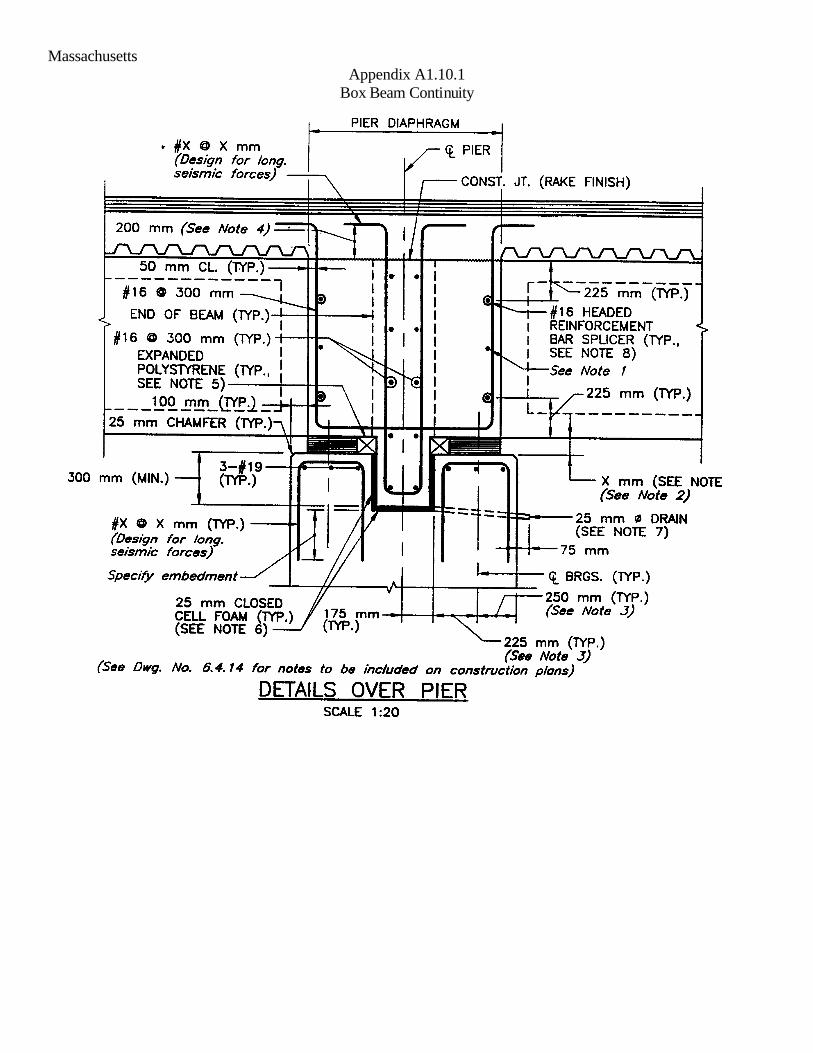
Massachusetts Appendix A1.10.1
Box Beam Continuity

Massachusetts Appendix A1.10.2
Pier Diaphragm Plan For Box Beam Continuity
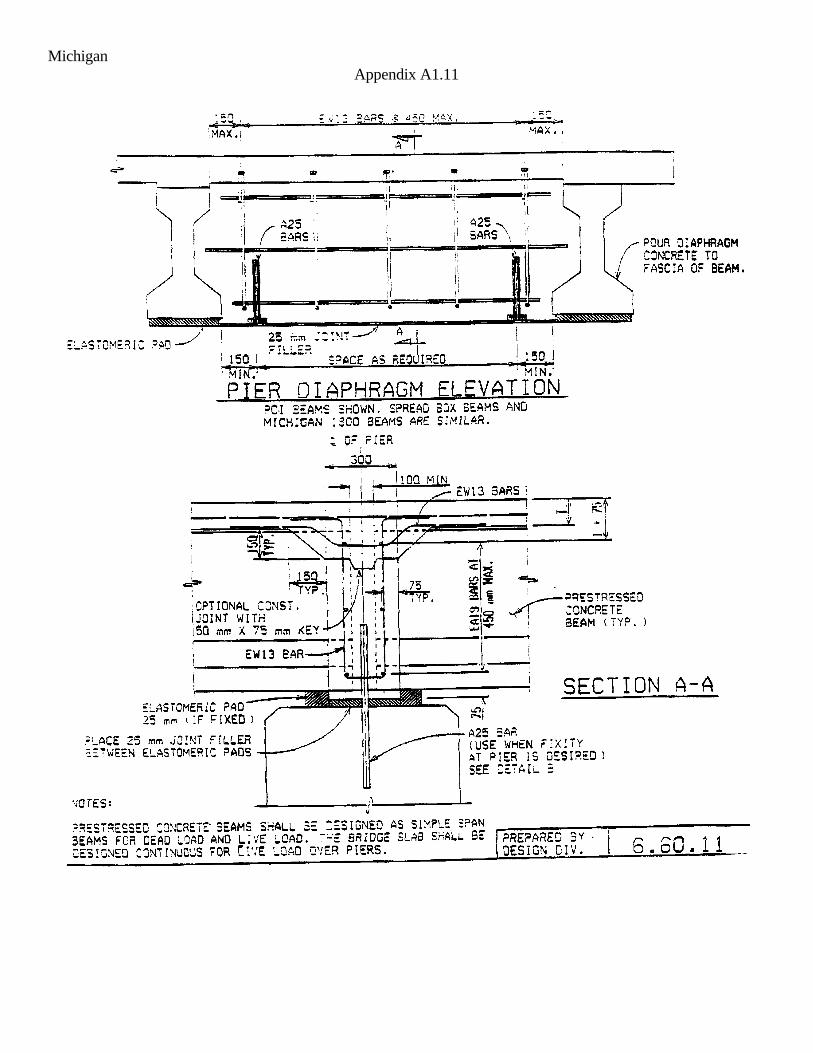
Michigan Appendix A1.11

Minnesota Appendix A1.12

Missouri Appendix A1.13
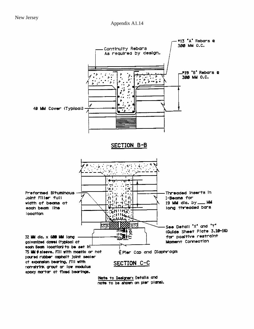
New Jersey Appendix A1.14
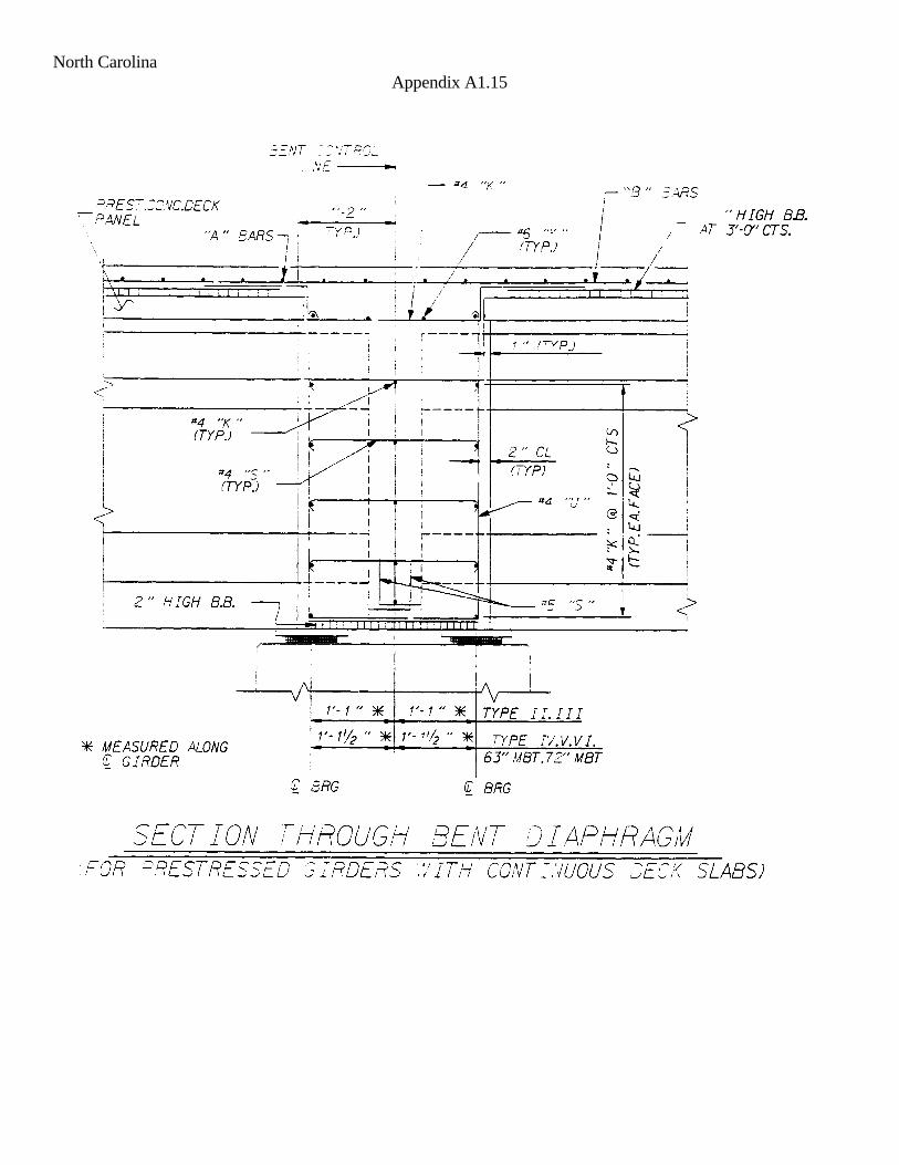
North Carolina Appendix A1.15

North Dakota Appendix A1.16

Ohio Appendix A1.17

Ohio Appendix A1.17.1

Oregon Appendix A1.18

Pennsylvania Appendix A1.19

Tennessee Appendix A1.20

Utah Appendix A1.21

Virginia Appendix A1.22

Washington State Appendix A1.23

Wisconsin Appendix A1.24

Wyoming Appendix A1.25

California Appendix A1.26

State Of New York Appendix A1.27