Embed Size (px)
Citation preview

Substructuring
Introduction This tutorial was completed using ANSYS 7.0 The purpose of the tutorial is to show the how to use substructuring in ANSYS. Substructuring is a procedure that condenses a group of finite elements into one super-element. This reduces the required computation time and also allows the solution of very large problems.
A simple example will be demonstrated to explain the steps required, however, please note that this model is not one which requires the use of substructuring. The example involves a block of wood (E =10 GPa v =0.29) connected to a block of silicone (E = 2.5 MPa, v = 0.41) which is rigidly attached to the ground. A force will be applied to the structure as shown in the following figure. For this example, substructuring will be used for the wood block.
The use of substructuring in ANSYS is a three stage process:
1. Generation Pass Generate the super-element by condensing several elements together. Select the degrees of freedom to save (master DOFs) and to discard (slave DOFs). Apply loads to the super-element
2. Use Pass Create the full model including the super-element created in the generation pass. Apply remaining loads to the model. The solution will consist of the reduced solution tor the super-element and the complete solution for the non-superelements.
3. Expansion Pass Expand the reduced solution to obtain the solution at all DOFs for the super-element.
Note that a this method is a bottom-up substructuring (each super-element is created separately and then assembled in the Use Pass). Top-down substructuring is also possible in ANSYS (the entire model is built, then
University of Alberta ANSYS Tutorials - www.mece.ualberta.ca/tutorials/ansys/AT/Substructuring/Substruct...
Copyright © 2001 University of Alberta

super-element are created by selecting the appropriate elements). This method is suitable for smaller models and has the advantage that the results for multiple super-elements can be assembled in postprocessing.
Expansion Pass: Creating the Super-element
Preprocessing: Defining the Problem
1. Give Generation Pass a Jobname Utility Menu > File > Change Jobname ...
Enter 'GEN' for the jobname
2. Open preprocessor menu ANSYS Main Menu > Preprocessor /PREP7
3. Create geometry of the super-element Preprocessor > Modeling > Create > Areas > Rectangle > By 2 Corners BLC4,XCORNER,YCORNER,WIDTH,HEIGHT
Create a rectangle with the dimensions (all units in mm):
XCORNER (WP X) = 0 YCORNER (WP Y) = 40 Width = 100 Height = 100
4. Define the Type of Element Preprocessor > Element Type > Add/Edit/Delete...
For this problem we will use PLANE42 (2D structural solid). This element has 4 nodes, each with 2 degrees of freedom (translation along the X and Y axes).
5. Define Element Material Properties Preprocessor > Material Props > Material Models > Structural > Linear > Elastic > Isotropic
In the window that appears, enter the following geometric properties for wood: i. Young's modulus EX: 10000 (MPa)
ii. Poisson's Ratio PRXY: 0.29
6. Define Mesh Size Preprocessor > Meshing > Size Cntrls > Manual Size > Areas > All Areas ...
For this example we will use an element edge length of 10mm.
7. Mesh the block Preprocessor > Meshing > Mesh > Areas > Free > click 'Pick All' AMESH,1
University of Alberta ANSYS Tutorials - www.mece.ualberta.ca/tutorials/ansys/AT/Substructuring/Substruct...
Copyright © 2001 University of Alberta

Solution Phase: Assigning Loads and Solving
1. Define Analysis Type Solution > Analysis Type > New Analysis > Substructuring ANTYPE,SUBST
2. Select Substructuring Analysis Options
It is necessary to define the substructuring analysis options
Select Solution > Analysis Type > Analysis Options
The following window will appear. Ensure that the options are filled in as shown.
Sename (the name of the super-element matrix file) will default to the jobname. In this case, the stiffness matrix is to be generated. With the option SEPR, the stiffness matrix or load matrix can be printed to the output window if desired.
3. Select Master Degrees of Freedom
Master DOFs must be defined at the interface between the super-element and other elements in addition to points where loads/constraints are applied.
Select Solution > Master DOFs > User Selected > Define
Select the Master DOF as shown in the following figure.
University of Alberta ANSYS Tutorials - www.mece.ualberta.ca/tutorials/ansys/AT/Substructuring/Substruct...
Copyright © 2001 University of Alberta

In the window that appears, set the 1st degree of freedom to All DOF
4. Apply Loads Solution > Define Loads > Apply > Structural > Force/Moment > On Nodes
Place a load of 5N in the x direction on the top left hand node
The model should now appear as shown in the figure below.
University of Alberta ANSYS Tutorials - www.mece.ualberta.ca/tutorials/ansys/AT/Substructuring/Substruct...
Copyright © 2001 University of Alberta

5. Save the database Utility Menu > File > Save as Jobname.db SAVE
Save the database to be used again in the expansion pass
6. Solve the System Solution > Solve > Current LS SOLVE
Use Pass: Using the Super-element The Use Pass is where we model the entire model, including the super-elements from the Generation Pass.
Preprocessing: Defining the Problem
1. Clear the existing database Utility Menu > File > Clear & Start New
2. Give Use Pass a Jobname Utility Menu > File > Change Jobname ... FILNAME, USE
Enter 'USE' for the jobname
University of Alberta ANSYS Tutorials - www.mece.ualberta.ca/tutorials/ansys/AT/Substructuring/Substruct...
Copyright © 2001 University of Alberta

3. Open preprocessor menu ANSYS Main Menu > Preprocessor /PREP7
Now we need to bring the Super-element into the model
4. Define the Super-element Type Preprocessor > Element Type > Add/Edit/Delete...
Select 'Super-element' (MATRIX50)
5. Create geometry of the non-superelement (Silicone) Preprocessor > Modeling > Create > Areas > Rectangle > By 2 Corners BLC4,XCORNER,YCORNER,WIDTH,HEIGHT
Create a rectangle with the dimensions (all units in mm):
XCORNER (WP X) = 0 YCORNER (WP Y) = 0 Width = 100 Height = 40
6. Define the Non-Superelement Type Preprocessor > Element Type > Add/Edit/Delete...
We will again use PLANE42 (2D structural solid).
7. Define Element Material Properties Preprocessor > Material Props > Material Models > Structural > Linear > Elastic > Isotropic
In the window that appears, enter the following geometric properties for silicone: i. Young's modulus EX: 2.5 (MPa)
ii. Poisson's Ratio PRXY: 0.41
8. Define Mesh Size Preprocessor > Meshing > Size Cntrls > Manual Size > Areas > All Areas ...
For this block we will again use an element edge length of 10mm. Note that is is imperative that the nodes of the non-superelement match up with the super-element MDOFs.
9. Mesh the block Preprocessor > Meshing > Mesh > Areas > Free > click 'Pick All' AMESH,1
10. Offset Node Numbering
Since both the super-element and the non-superelement were created independently, they contain similarly numbered nodes (ie both objects will have node #1 etc.). If we bring in the super-element with similar node numbers, the nodes will overwrite existing nodes from the non-superelements. Therefore, we need to offset the super-element nodes
University of Alberta ANSYS Tutorials - www.mece.ualberta.ca/tutorials/ansys/AT/Substructuring/Substruct...
Copyright © 2001 University of Alberta
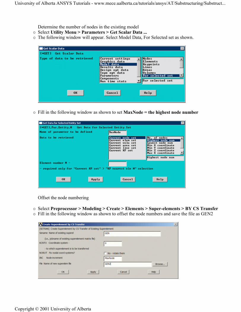
Determine the number of nodes in the existing model Select Utility Menu > Parameters > Get Scalar Data ... The following window will appear. Select Model Data, For Selected set as shown.
Fill in the following window as shown to set MaxNode = the highest node number
Offset the node numbering
Select Preprocessor > Modeling > Create > Elements > Super-elements > BY CS Transfer Fill in the following window as shown to offset the node numbers and save the file as GEN2
University of Alberta ANSYS Tutorials - www.mece.ualberta.ca/tutorials/ansys/AT/Substructuring/Substruct...
Copyright © 2001 University of Alberta

Read in the super-element matrix
Select Preprocessor > Modeling > Create > Elements > Super-elements > From .SUB File... Enter 'GEN2' as the Jobname of the matrix file in the window (shown below)
Utility Menu > Plot > Replot
11. Couple Node Pairs at Interface of Super-element and Non-Superelements
Select the nodes at the interface Select Utility Menu > Select > Entities ... The following window will appear. Select Nodes, By Location, Y coordinates, 40 as shown.
Couple the pair nodes at the interface
Select Preprocessor > Coupling / Ceqn > Coincident Nodes
Re-select all of the nodes
University of Alberta ANSYS Tutorials - www.mece.ualberta.ca/tutorials/ansys/AT/Substructuring/Substruct...
Copyright © 2001 University of Alberta

Select Utility Menu > Select > Entities ... In the window that appears, click 'Nodes > By Num/Pick > From Full > Sele All'
Solution Phase: Assigning Loads and Solving
1. Define Analysis Type Solution > New Analysis > Static ANTYPE,0
2. Apply Constraints Solution > Define Loads > Apply > Structural > Displacement > On Lines
Fix the bottom line (ie all DOF constrained)
3. Apply super-element load vectors
Determine the element number of the super-element (Select Utility Menu > PlotCtrls > Numbering...)
You should find that the super-element is element 41
Select Solution > Define Loads > Apply > Load Vector > For Super-element
The following window will appear. Fill it in as shown to apply the super-element load vector.
4. Save the database Utility Menu > File > Save as Jobname.db SAVE
Save the database to be used again in the expansion pass
5. Solve the System Solution > Solve > Current LS SOLVE
General Postprocessing: Viewing the Results
University of Alberta ANSYS Tutorials - www.mece.ualberta.ca/tutorials/ansys/AT/Substructuring/Substruct...
Copyright © 2001 University of Alberta

1. Show the Displacement Contour Plot General Postproc > Plot Results > Contour Plot > Nodal Solution ... > DOF solution, Translation USUM PLNSOL,U,SUM,0,1
Note that only the deformation for the non-superelements is plotted. This results agree with what was found without using substructuring (see figure below).
University of Alberta ANSYS Tutorials - www.mece.ualberta.ca/tutorials/ansys/AT/Substructuring/Substruct...
Copyright © 2001 University of Alberta

Expansion Pass: Expanding the Results within the Super-element To obtain the solution for all elements within the super-element you will need to perform an expansion pass.
Preprocessing: Defining the Problem
1. Clear the existing database Utility Menu > File > Clear & Start New
2. Change the Jobname back to Generation pass Jobname Utility Menu > File > Change Jobname ... FILNAME, GEN
Enter 'GEN' for the jobname
3. Resume Generation Pass Database Utility Menu > File > Resume Jobname.db ... RESUME
Solution Phase: Assigning Loads and Solving
1. Activate Expansion Pass
University of Alberta ANSYS Tutorials - www.mece.ualberta.ca/tutorials/ansys/AT/Substructuring/Substruct...
Copyright © 2001 University of Alberta

Enter the Solution mode by selecting Main Menu > Solution or by typing /SOLU into the command line.
Type 'EXPASS,ON' into the command line to initiate the expansion pass.
2. Enter the Super-element name to be Expanded
Select Solution > Load STEP OPTS > ExpansionPass > Single Expand >Expand Superelem ...
The following window will appear. Fill it in as shown to select the super-element.
3. Enter the Super-element name to be Expanded
Select Solution > Load Step Opts > ExpansionPass > Single Expand > By Load Step...
The following window will appear. Fill it in as shown to expand the solution.
4. Solve the System Solution > Solve > Current LS SOLVE
General Postprocessing: Viewing the Results
1. Show the Displacement Contour Plot General Postproc > Plot Results > (-Contour Plot-) Nodal Solution ... > DOF solution, Translation
University of Alberta ANSYS Tutorials - www.mece.ualberta.ca/tutorials/ansys/AT/Substructuring/Substruct...
Copyright © 2001 University of Alberta
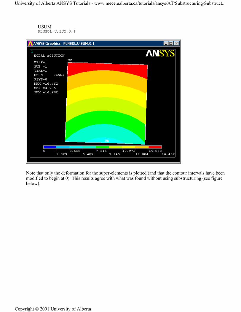
USUM PLNSOL,U,SUM,0,1
Note that only the deformation for the super-elements is plotted (and that the contour intervals have been modified to begin at 0). This results agree with what was found without using substructuring (see figure below).
University of Alberta ANSYS Tutorials - www.mece.ualberta.ca/tutorials/ansys/AT/Substructuring/Substruct...
Copyright © 2001 University of Alberta

Command File Mode of Solution The above example was solved using the Graphical User Interface (or GUI) of ANSYS. This problem has also been solved using the ANSYS command language interface that you may want to browse. Open the file and save it to your computer. Now go to 'File > Read input from...' and select the file.
University of Alberta ANSYS Tutorials - www.mece.ualberta.ca/tutorials/ansys/AT/Substructuring/Substruct...
Copyright © 2001 University of Alberta