Embed Size (px)
Citation preview

Shaking Table Substructuring for Soil
Structure Interaction
Tang, Z., Dietz, M., Li, Z., and Taylor, C.
07 June 2013
1

Contents
• Introduction
• Control issues
• Benchmark test
• Substructuring the benchmark
• Summary
2
07 June 2013

• The seismic response of a soil-foundation-structure system is governed by the interplay between the dynamics of the soil, the structure and the earthquake .
• Analytical and numerical techniques have been and are being developed to aid with safe design of SSI systems
• Physical modelling is required to validate proposed design tools.
Introduction 3
07 June 2013
Soil Structure Interaction

Option 1 - Site tests
• Real soil profiles
• Large scale testing
• No control of ground motion
• Used to estimate how SSI affects damping and natural frequencies
Introduction 4
07 June 2013
Experimental investigation of SSI
Site test (Shouping,2004)

Option 2 - Laboratory tests
• The soil-structure system is the test specimen
• Specialist apparatus required – shaking table, centrifuge, soil container.
• Modelling is at small scales due to the size/capacity limitations of test apparatus
Introduction 5
07 June 2013
Shaking table test
(Tagawa,2006)

Option 3 – Real time dynamic substructuring RTDS
• The test structure is split into two linked parts
• The unpredictable component is tested in the lab
• The remainder is modelled numerically
• Interface force is measured
• Commensurate motion applied by a transfer system
Introduction 6
07 June 2013

Shaking table RTDS control
• Historically, RTDS has used standalone actuators
• SSI RTDS demands the use of a shaking table
RTDS control 7
07 June 2013
RTDS control 8
07 June 2013
Generalised RTDS control loop
Challenge I – to obtain a realistic desired displacement.
Challenge 2 – to achieve stable and accurate RTDS by nullifying transfer system dynamics using a controller.

• Most prevalent control scheme is delay compensation
yP(t) = u(t-t)
Gts = yP(s)/u(s)
= e-twi
• Assumptions inherent in the time delay model: (i) Constant magnitude, i.e. |Gts(s)| = 1
(ii)Phase proportional to frequency, i.e. ‹Gts (s) = wt
RTDS control 9
07 June 2013
Time-delay model

Transfer system dynamics
RTDS control 10
07 June 2013
Standalone actuator Shaking table

• Dynamic stability of closed loop feedback systems analysed using the root locus technique.
• Physical to numerical mass ratio is taken to be the variable parameter of interest.
• Stability predictions are reliable only once comprehensive transfer system dynamics are taken into account
RTDS control 11
07 June 2013
The effect of transfer system dynamics on RTDS stability

RTDS control 12
07 June 2013
The effect of transfer system dynamics on RTDS accuracy
Control schemes that do not account for comprehensive transfer system dynamics such as delay compensation have a narrow viable bandwidth curtailed at low frequencies.
RTDS control 13
07 June 2013
13
07 June 2013
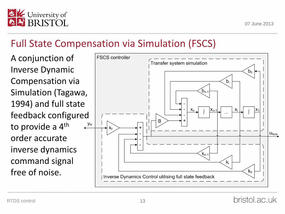
Full State Compensation via Simulation (FSCS)
A conjunction of Inverse Dynamic Compensation via Simulation (Tagawa, 1994) and full state feedback configured to provide a 4th order accurate inverse dynamics command signal free of noise.

RTDS control 14
07 June 2013
+
+
yP
e
u Shaking table
TableGFSCS controller
FSCSGufscs
ke
+ -
+
-
r yN
freaction
Numerical model
NrG
Physical substructure
PG
Constraint dynamics
NfG
f
Full State Compensation via Simulation (FSCS)
Error feedback (via the ke parameter) can be used to compensate for discrepancies between the dynamics of the real and virtual shaking tables.

RTDS control 15
07 June 2013
FSCS Accuracy
• Transfer function relatively flat
• Small delay remains (2-3ms)
• Feedback (ke) enhances low frequency performance

RTDS control 16
07 June 2013
FSCS Stability
• Compared to the no controller (‘NC’) and delay compensated (‘DC’) cases, FSCS generally enhances stability
• Exception is when structures are very lightly damped
Here: ke = 0, w = wN = wP,
x = xN = xP, s = mP/(mP+mN)

Benchmark SSI test
• Structure
• Soil
• Soil Container
• Shaking table
Benchmark test 17
07 June 2013

Benchmark test 18
07 June 2013
Shaking table

• Filled with dry sand (Hostun S28) and excited in the long-direction
• Restraining frame restricts x and z vibrations
• Rough end walls & base, lubricated side walls
• Composite stiffness of box significantly less than that of deposit – the deposit drives the response
Benchmark test 19
07 June 2013
Shear stack soil container
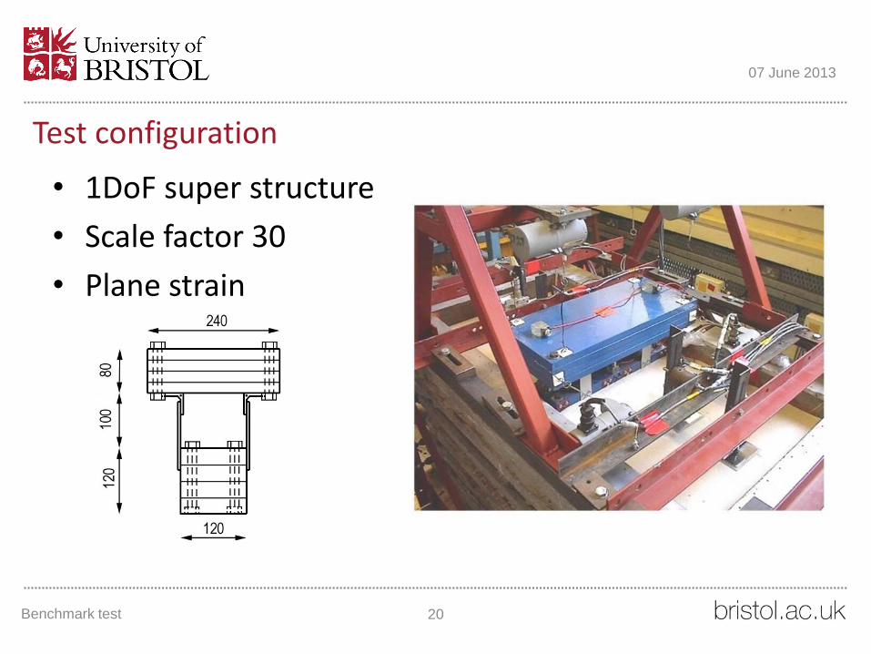
• 1DoF super structure
• Scale factor 30
• Plane strain
Benchmark test 20
07 June 2013
Test configuration

Benchmark test 21
07 June 2013
Frequency response of the benchmark test system
Sand deposit – 29Hz
Fixed base oscillator
– 23Hz
SSI system – 11Hz

Substructuring the benchmark 22
07 June 2013
Fixed-base parameters: • mP = 50kg • wP = 23Hz • xP = 5%
Modelling SSI frequency response: • mN = 120kg • wN = 16Hz • xN = 14%
RTDS implementation

Substructuring the benchmark 23
07 June 2013
Vra
nce
a (1
97
7)
Friu
li (1
97
6)
Response acceleration time history Response acceleration power spectra

Substructuring the benchmark 24
07 June 2013
RTDS Benchmark
1x
2x
Excitation magnitude

• Agreement between RTDS and benchmark test is good up to 5Hz and reasonable up to 10Hz
• Rocking mode becomes dominant after 10Hz
• Multi-axis RTDS required to model SSI phenomena comprehensively
• Agreement worsens as amplitude of excitation increases and the response of the linear soil model diverges from the nonlinear sand deposit
• More realistic soil model required
Substructuring the benchmark 25
07 June 2013
Summary
• With ‘complex’ transfer systems, application of the time delay model can result in poor RTDS performance.
• RTDS stability predictions become reliable once comprehensive transfer system dynamics are accounted for.
• A new controller, Full State Compensation via Simulation (FSCS), offers an enhanced RTDS performance compared to delay compensation.
Summary 26
07 June 2013

Summary 27
07 June 2013
Summary
• Uni-axial RTDS cannot simulate the phenomena associated with SSI. Multi-axis RTDS is required for SSI systems exhibiting rocking/uplift.
• Linear lumped-parameter soil-foundation models limit the scope of RTDS tests. Alternatively, SSI nonlinearites (elastoplastic soil response, foundation rocking/sliding/ uplift) can be incorporated within the RTDS algorithm using numerical models of increased sophistication.


![SOIL STRUCTURE AND FABRIC - civil.emu.edu.trcivil.emu.edu.tr/courses/civl553/Lec10 Fabric [Compatibility Mode].pdf · SOIL STRUCTURE AND FABRIC ... SOIL FABRIC AND STRUCTURE ... Flocculation](https://img.dokumen.tips/doc/110x75/5a9fcf6e7f8b9a6c178d397e/soil-structure-and-fabric-civilemuedu-fabric-compatibility-modepdfsoil-structure.jpg)