Embed Size (px)
Citation preview

OTC 24273-MS
SPRINGSTM: subsea seawater treatment – case study Pierre PEDENAUD, Luc RIVIERE, TOTAL SA, Raymond HALLOT, Stéphane ANRES, SAIPEM, Graeme SKIVINGTON, VEOLIA Water.
Copyright 2013, Offshore Technology Conference This paper was prepared for presentation at the Offshore Technology Conference Brasil held in Rio de Janeiro, Brazil, 29–31 October 2013. This paper was selected for presentation by an OTC program committee following review of information contained in an abstract submitted by the author(s). Contents of the paper have not been reviewed by the Offshore Technology Conference and are subject to correction by the author(s). The material does not necessarily reflect any position of the Offshore Technology Conference, its officers, or members. Electronic reproduction, distribution, or storage of any part of this paper without the written consent of the Offshore Technology Conference is prohibited. Permission to reproduce in print is restricted to an abstract of not more than 300 words; illustrations may not be copied. The abstract must contain conspicuous acknowledgment of OTC copyright.
Abstract New local subsea processing systems will need to be developed to allow remotely located satellite oil fields to be produced economically. One such system treats seawater for injection into the reservoir. As reservoir waters often contain elevated concentrations of barium or calcium, treatment systems need membranes to remove any sulfates that may form in the seawater before it is injected into the reservoir, in order to avoid severe scaling. SPRINGSTM (Subsea PRocess and INjection Gear for Seawater) is a collaboration project between Total, Saipem, Veolia Water and VWS Westgarth. It was initiated in 2007 and aims to provide robust solutions featuring the use of membranes for treating seawater on the sea bed in deepwater areas. SPRINGSTM has now reached qualification stage and a first industrial application is planned for 2015. This paper describes the SPRINGSTM development project, including an update on the latest progress to date. It presents a specific case study conducted in the Gulf of Guinea which illustrates the commercial and technological advantages, along with the limitations, of deploying this technology for future remote applications. It compares the conventional field architecture utilized in conjunction with water injection from FPSO topsides with the architecture required for a SPRINGSTM solution on the ocean floor. The information provided allows operators to consider an alternative development strategy for the application of membranes to water injection in remote satellite fields. Introduction The development of isolated subsea fields, far from existing production centres or from the shore, and sometimes in very harsh environments such as deep offshore, West of Shetlands or the Arctic seas, has led Total E&P to develop new building blocks of innovative subsea processing. One block required for the development of subsea oilfields is the treatment of seawater for injection (sometimes going as far as desulfation, if the reservoir water contains significant levels of barium or calcium), to maintain pressure and optimize recovery of reserves.

2 OTC 24273-MS
Figure 1: Typical subsea configuration In conventional offshore developments, seawater is lifted and treated on the topsides facilities. Seawater treatment systems installed by Total E&P in recent years, mainly on deep offshore FPSOs, usually include: a pre-filtration unit, a fine filtration unit, a deoxygenation system and a nano-filtration unit (for desulfation of seawater). In 2007, to meet the challenge of producing remote subsea reservoirs, Total E&P launched a specific research program in collaboration with Saipem, Veolia Water and VWS Westgarth (a Veolia subsidiary specialized in membrane technology) targeting seafloor treatment of seawater for injection: SPRINGSTM (Subsea PRocess and INjection Gear for Seawater) The SPRINGSTM technology is to perform subsea seawater treatment, which may include sulfate removal, and water injection into the reservoir. The technology is based on sulfate removal unit (SRU) by nanofiltration membranes which have been widely used on topsides for several years. The targeted water depth ranges from 400 to 3000 meters. Case study The field is a reservoir, located 24 km north of an existing FPSO in 400 to 500 meter water depth. A preliminary study was conducted in 2011 which recommended the tie back to the FPSO as the most economic scenario. Regarding sea water injection for enhanced oil recovery the preliminary development schematic proposed was a new 10 inch injection line to feed 3 new injector wells, situated at 18 km for the first well and up to 24 km for the third well from the FPSO. This is the conventional solution described in the figure 2.
OTC Number 3
Figure 2: Conventional solution
The reservoir contains a high content of barium, typically around 200 mg/l and therefore the sea water injected must be desulfated by a nanofiltration membrane process. Debottlenecking on the FPSO topside is necessary to obtain the 42000 bwpd to feed the three wells with a well head injection pressure of 67 bar at the required water quality which is less than 40 mg/l of remaining sulfate. An alternative solution is possible based on the SPRINGSTM technology. In this case, as described in figure 3, the sea water is taken and treated sub-sea which reduce the length of the 10 inch injection line to only 7 km and requires the installation of a power and control umbilical of 18 km. The injection line feeds the wells via two in-line tees (ILT) and one flow line end termination (FLET).
Figure 3: SPRINGSTM solution
This case study is an application of the work performed and the results of the previous development phases including a feasibility study, a conceptual study, hyperbaric tests on nanofiltration membranes, and a conceptual study of the Subsea Test Unit described below. Screening and conceptual studies were performed between 2008 and 2010 and showed that there was nothing to hinder the development of this subsea technology, although it was accepted that, as deoxygenation would not be

4 OTC 24273-MS
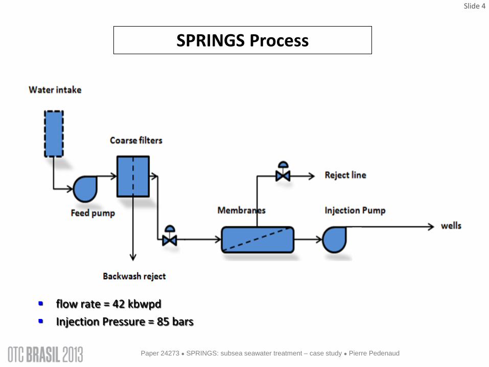
practicable in deep water, corrosion resistant alloys would be needed for the injection tubing. Subsea operation of a seawater treatment unit requires a process capable of operating at the hydrostatic pressure of the water column above. While much of the hardware involved (pumps, valves, instruments, etc.) is already field-proven in deepwater applications, this is not true of the membranes. Qualification testing of membrane performance under hyperbaric conditions was therefore considered fundamental to any further development of the concept. The hyperbaric tests were completed successfully in October 2011, confirming that the membranes’ integrity and performance were both within acceptable limits. Altough the membranes had successfully passed the tests in the laboratory, they could not be fully qualified until they had been operated under real conditions. The SPRINGSTM partners therefore set about designing a ‘Subsea Test Unit’ (STU) to measure the rate of fouling and the in situ performance of the membranes in subsea conditions. The STU is a subsea module – essentially comprising pumps, backwashable coarse filters and membranes – which is suspended by an umbilical (in the same way as an ROV) from a floating production unit or support vessel. Since water quality varies significantly from one location to another, we anticipe a requirement to utilize the STU prior to each application of the SPRINGSTM solution, with the rate of fouling being a key element in the decision to deploy the technology. Before beginning construction of the STU, its main components were tested in a tank of seawater for correct operation and endurance, including resistance to wear, internal corrosion and fouling due to deposits, micro-organisms, etc. These former studies and tests have been described in a previous paper (reference 1) SPRINGSTM Process The SPRINGSTM process architecture is given in figure 4. It includes a water intake equipped with a buoyancy strainer with typically 2 mm screening and is located around 100 m above the mud line to avoid sucking suspended solids from the mud. The water is then pumped to automatic backwashable coarse filters to remove particles above 50 micron. Two coarse filters units were included in addition to the duty units to allow for one in backwash and one as a spare.
Figure 4: SPRINGSTM process
The filtered water is then sent to nanofiltration membranes for sulfate removal. Only part of the water passes through the membranes, the permeate with a sulfate content below 40 mg/l. The other part (the concentrate) is rejected to the sea via a 30m flexible jumper, a 100 m long line and a discharge nozzle. The permeate is then pumped to feed the wells using the injection line.
OTC Number 5
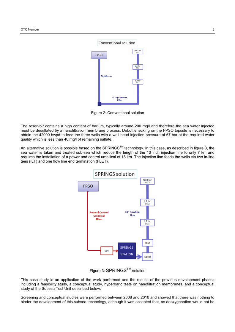
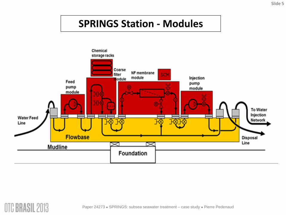
Regarding the pressure profile the inlet pressure is 50 bar due to the water depth and the injection pressure 85 bar. The unit is not equipped with a clean in place (CIP) system for the membrane cleaning; the cleaning will be done onshore by replacing the membrane module when necessary. The cleaning frequency is expected to be twice a year typically. However to avoid membrane biofouling, biocide will be stored in the SPRINGSTM module and injected in the process. SPRINGSTM station modules This part is a key aspect for the SPRINGSTM design, and the modules have been redesigned compared to the first screening and conceptual studies. The modularization drivers were functionality and maintainability. The result of the study is a new architecture based on a flat flowbase on a suction pile, vertical connections beneath modules and stacked modules such as chemicals storage racks and the subsea control module (SCM). Figure 5 shows this architecture and figure 6 a typical layout.
Figure 5: SPRINGSTM subsea station architecture
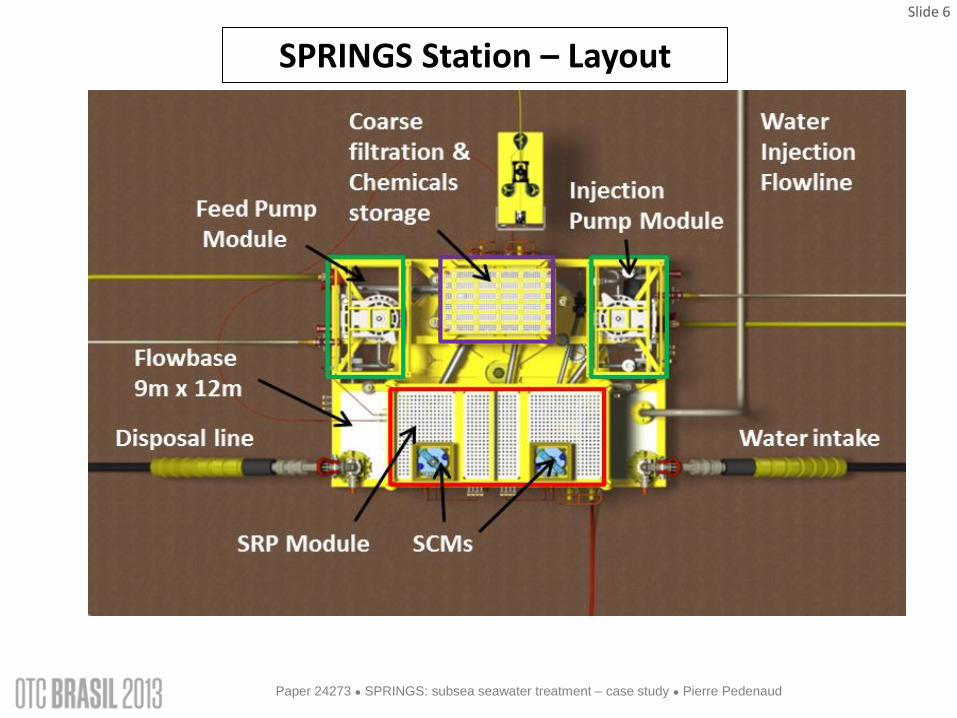
Figure 6: SPRINGSTM subsea station layout
6 OTC 24273-MS
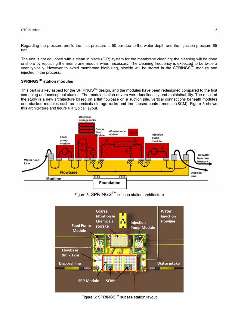
Based on this the overall dimensions are 12m x 9m x 14m (Height) with a weight of 290 T excluding piles. Each module is then easily retrievable by the new generation of IMR (Inspection, Maintenance and Repair) vessels for deep and ultra-deep offshore fields maintenance such as the BOURBON EVOLUTION 800 SERIES. The chemical storage racks have been calculated for one re fill per year. The estimated volume is 7 m3; it can be seen at the top of the 3D view of the SPRINGSTM subsea station on figure 7.
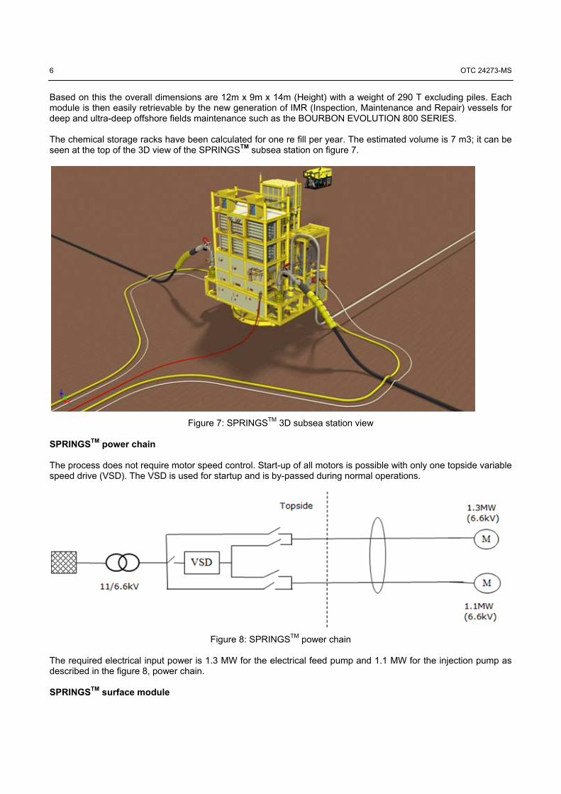
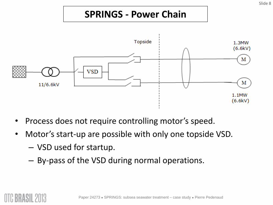
Figure 7: SPRINGSTM 3D subsea station view SPRINGSTM power chain The process does not require motor speed control. Start-up of all motors is possible with only one topside variable speed drive (VSD). The VSD is used for startup and is by-passed during normal operations.
Figure 8: SPRINGSTM power chain The required electrical input power is 1.3 MW for the electrical feed pump and 1.1 MW for the injection pump as described in the figure 8, power chain. SPRINGSTM surface module

OTC Number 7
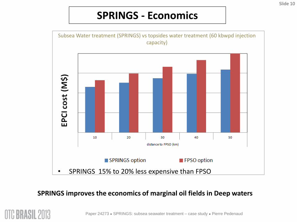
The surface module requirement is limited to the typical topside power and control system. It will require a size of approximately 6m x 13m x 5m with a weight of 170 tons. The topside equipment consist of the master control station (MCS) and the electrical power and communication units (EPCU) interface with the FPSO power system and UPS (Uninterruptible Power Supply (battery)); one VSD, one transformer, the pump barrier fluid HPU (Hydraulic Power Unit) and the electrical and fiber optic junction. SPRINGSTM economics A general economics study was performed to compare the EPCI cost of the SPRINGSTM compared to the seawater treatment debottlenecking on an FPSO. A sensitivity study on the distance between the FPSO and the injector wells location has been completed. The results are given in figure 9. As expected the economic advantage of the SPRINGSTM subsea station increases with the distance from the FPSO.
Figure 9: SPRINGSTM economics The SPRINGSTM unit is 15 to 20 percent less expensive than the FPSO option, depending on the distance from the wells to the FPSO. Concerning the OPEX the elements to take into consideration are the planned interventions performed by an on-site IMR vessel with two interventions per year for the membrane module and once intervention per year for refilling the chemical storage. The intervention sequence is the transit to port, loading of spare modules, then transit to offshore field and replacement of spare modules. In the case study the distance from port to field is about 300 km. It has to be noted that IMR vessel mobilization and transit can be optimized by combining with other field operations. Spare modules will also be equired for planned or unplanned interventions, typically one spare membrane module, one spare chemical module, and one or two spare pump modules depending on the type of maintenance contract with the pump manufacturer. Cleaning of the membrane also has to be taken into account depending on the fouling rate.

8 OTC 24273-MS
Conclusions The development of remote subsea oilfields, located far away from existing production centres or from the shore, in very difficult environments such as deep offshore, West of Shetlands or the Arctic seas, will require more local subsea processing in the future to be economically viable. The treatment of seawater for injection, desulfation of seawater included, is one of the local subsea processing needs for which there is currently no solution. The SPRINGSTM project, launched six years ago by Total with Saipem and Veolia, aims to provide a complete solution for this important aspect of the development of subsea oilfields. This case study shows the potential and details of the SPRINGSTM solution, many other cases being on the list. Even if systems like this will be challenging to operate in subsea environments, we are confident that we will effectively be implementing such complex solutions in the coming years, building on the success of many recent subsea processing systems installed by Total in other challenging situations. References 1 Luc Rivière / Pierre Pedenaud (TOTAL SA), Stéphanie Abrand / Stéphane Anres (SAIPEM), Didier Bigeonneau (VEOLIA Water), Wayne Evans / Graeme Skivington (VWS Westgarth). DOT 2012 Perth “SPRINGSTM - subsea seawater treatment for oilfield water injection” Nomenclature BWPD = Barrel water per day EPCU = electrical power and communication units E&P = Exploration and Production FLET = flowline end termination FO = Fiber Optic FPSO= Floating Production Storage Offloading HPU = Hydraulic Power Unit ILT = in line tee IMR = Inspection Maintenance and Repair MCS = master control station PLET = pipeline end termination ROV = Remote Operated Vehicle SCM = subsea control module SPRINGSTM= Subsea PRocess and INjection Gear for Seawater) SRU=: Sulfate Removal Unit STU =: Subsea Test Unit SUT = subsea umbilical termination UPS = Uninterruptible Power Supply (battery) VSD = variable speed drive Acknowledgement The authors would like to thank TOTAL, SAIPEM and VEOLIA Water for their kind permission to publish this paper.

Slide 1
SPRINGS: subsea seawater treatment
– case study
Pierre PEDENAUD, Luc RIVIERE, Total SA, Raymond HALLOT, Stéphane ANRES, Saipem, Graeme
SKIVINGTON, Veolia Water.
Paper OTC 24273

Paper # • Paper Title • Presenter’s Name
Slide 2
Vision of Deep Offshore Oil Satellite All Electrical System, Mud-line activation, Electrical heating of flowline, Resident maintenance tool, Subsea Seawater
Treatment & Injection, Local power generation, Subsea observatories
Subsea Chemical Storage & Injection
Subsea G/L Separation
Subsea Seawater Treatment & Injection
Local Power Generation
Subsea Observatory
Subsea Boosting
Subsea Inspection & Intervention
All Electrical Systems
SPRINGS = Subsea PRocess and INjection Gear for Seawater
SPRINGS is one of the foundations of subsea development for oil fields.
Paper 24273 ● SPRINGS: subsea seawater treatment – case study ● Pierre Pedenaud

Paper # • Paper Title • Presenter’s Name
Slide 3
SPRINGS - Case Study
3 injection wells at Water Depth 400m to 500m
Wells situated at 18 km (1st well) up to 24 km (3rd well) from FPSO
SPRINGS station placed at 500m WD, at 18 km from FPSO
Paper 24273 ● SPRINGS: subsea seawater treatment – case study ● Pierre Pedenaud
Paper # • Paper Title • Presenter’s Name
Slide 4
SPRINGS Process
flow rate = 42 kbwpd
Injection Pressure = 85 bars
Paper 24273 ● SPRINGS: subsea seawater treatment – case study ● Pierre Pedenaud
Paper # • Paper Title • Presenter’s Name
Slide 5
SPRINGS Station - Modules
Paper 24273 ● SPRINGS: subsea seawater treatment – case study ● Pierre Pedenaud
Paper # • Paper Title • Presenter’s Name
Slide 6
SPRINGS Station – Layout
Paper 24273 ● SPRINGS: subsea seawater treatment – case study ● Pierre Pedenaud

Paper # • Paper Title • Presenter’s Name
Slide 7
SPRINGS Station – 3D view
Dimensions = 12m x 9m x 14m (Height)
Weight = 290 T without pile
Paper 24273 ● SPRINGS: subsea seawater treatment – case study ● Pierre Pedenaud
Paper # • Paper Title • Presenter’s Name
Slide 8
SPRINGS - Power Chain
• Process does not require controlling motor’s speed.
• Motor’s start-up are possible with only one topside VSD.
– VSD used for startup.
– By-pass of the VSD during normal operations.
Paper 24273 ● SPRINGS: subsea seawater treatment – case study ● Pierre Pedenaud

Paper # • Paper Title • Presenter’s Name
Slide 9
SPRINGS – Surface Module
• Typical topside power and control system – ≈ 6m x 13m x 5m; ≈ 170tons
• Topside equipment: – MCS and EPCU interface with FPSO power system and UPS
– 1 VSD, 1 transformer, Pump barrier fluid HPU, Electrical and FO Junction
•SPRINGS is the only way to develop satellites with minimal modifications on the FPSO, which contributes to reduce :
• FPSO production shutdowns, • Risks during construction.
Paper 24273 ● SPRINGS: subsea seawater treatment – case study ● Pierre Pedenaud
Paper # • Paper Title • Presenter’s Name
Slide 10
SPRINGS - Economics
Subsea Water treatment (SPRINGS) vs topsides water treatment (60 kbwpd injection capacity)
• SPRINGS 15% to 20% less expensive than FPSO
SPRINGS improves the economics of marginal oil fields in Deep waters
Paper 24273 ● SPRINGS: subsea seawater treatment – case study ● Pierre Pedenaud

Slide 11
CONCLUSIONS
Treatment of seawater for injection for the development of remote subsea oilfields, desulfation included, is
possible subsea and economically viable.

Slide 12
CONCLUSIONS
Even if SPRINGS will be challenging to operate, we are confident that we will be implementing such solutions in
the coming years…
… building on the success of many recent subsea processing systems installed by Total in other challenging
situations.

Slide 13
Thank you
Any Questions ?

Slide 14
DISCLAIMER and COPYRIGHT RESERVATION The TOTAL GROUP is defined as TOTAL S.A. and its affiliates and shall include the party making the
presentation. Disclaimer This presentation may include forward-looking statements within the meaning of the Private
Securities Litigation Reform Act of 1995 with respect to the financial condition, results of operations, business, strategy and plans of TOTAL GROUP that are subject to risk factors and uncertainties caused by changes in, without limitation, technological development and innovation, supply sources, legal framework, market conditions, political or economic events.
TOTAL GROUP does not assume any obligation to update publicly any forward-looking statement, whether as a result of new information, future events or otherwise. Further information on factors which could affect the company’s financial results is provided in documents filed by TOTAL GROUP with the French Autorité des Marchés Financiers and the US Securities and Exchange Commission.
Accordingly, no reliance may be placed on the accuracy or correctness of any such statements. Copyright All rights are reserved and all material in this presentation may not be reproduced without the
express written permission of the TOTAL GROUP.