Embed Size (px)
Citation preview

I N STR UCTION MAN UAL
OR IG I NAL I N STR UCTION S /TRAN S LATION OF OR IG I NAL I N STR UCTION S R EAD AN D U N D E R STAN D TH I S MAN UAL PR IOR TO OPE RATI NG OR
S E RVICI NG TH I S PROD UCT
Submersible Bilge Pumps CARTR I DG E L-S E R I E S L450, L550, L650, L750
I B-103 R05 (02/2012)

2
Garanti 3 årWarranty 3 years Garantie 3 Jahren
Garantie 3 ansGarantía 3 añosGaranzia 3 anni
INDEX - INDICE
Svenska ....................................................................................................................................................................3English .....................................................................................................................................................................6Deutsch ....................................................................................................................................................................9Français ................................................................................................................................................................ 12Español ................................................................................................................................................................ 15Italiano ................................................................................................................................................................... 18
Besök www.johnson-pump.com för mer information om vår världsomspännande organisation, våra godkännanden, certifieringar och lokala representanter. SPX Corporation förbehåller sig rätten att ändra design och material utan föregående avisering. Designelement, konstruktionsmaterial och dimensioner som beskrivs i denna bulletin gäller endast som information och skall alltid bekräftas skriftligt för att vara gällande.
For more information about our worldwide locations, approvals, certifications, and local representatives, please visit www.johnson-pump.com. SPX Corporation reserves the right to incorporate our latest design and material changes without notice or obligation. Design features, materials of construction and dimensional data, as described in this bulletin, are provided for your information only and should not be relied upon unless confirmed in writing.
Für weitere Informationen über unsere weltweiten Standorte, Zulassungen, Zertifizierungen und unsere Vertreter vor Ort, besuchen Sie bitte unsere Webseite: www.johnson-pump.com. Die SPX Corporation behält sich das Recht vor, die neuesten Konstruktions- und Werkstoffänderungen ohne vorherige Ankündigung und ohne Verpflichtung hierzu einfließen zu lassen. Konstruktive Ausgestaltungen, Werkstoffe sowie Maßangaben, wie sie in dieser Mitteilung beschrieben sind, sind nur zur Information. Alle Angaben sind unverbindlich, es sei denn, sie wurden schriftlich bestätigt.
Pour plus d’information sur nos succursales internationales, nos approbations, nos certifications et nos représentants locaux, veuillez consulter notre site Internet au www.johnson-pump.com. SPX Corporation se réserve le droit d’incorporer nos plus récents concepts ainsi que tout autre modification importante sans préavis ou obligation. Les éléments décoratifs, matériaux de construction et les données dimensionnelles, tels qu’énoncés dans ce communiqué, sont fournis pour votre information seulement et ne doivent pas être considérés comme officiels à moins d’avis contraire par écrit.
Para más información sobre nuestras oficinas a nivel mundial, aprobaciones, certificaciones y representantes locales, por favor visite www.johnson-pump.com. SPX Corporation se reserva el derecho de incorporar nuestro diseño más reciente y cambios materiales sin necesidad de notificación previa u obligación de ningún tipo. Características de diseño, materiales de construcción y dimensiones, tal y como están descritas en este boletín, son proporcionadas sólo con fines informativos y no deben ser usados como referencia a menos que sean confirmados por escrito.
Per ottenere maggiori informazioni sulle nostre sedi nel mondo, autorizzazioni, certificazioni, e rappresentanti locali, potete visitare il sito www.johnson-pump.com. La SPX Corporation si riserva il diritto di apportare cambiamenti ai propri design e materiali senza preavviso o vincolo. Le caratteristiche del design, i materiali di costruzione e i dati dimensionali, così come descritti nel presente bollettino, sono forniti solo per vostra informazione e non saranno oggetto di obbligazione salvo autorizzazione confermata per iscritto.
Made in USA

3Översättning av originalinstruktionerna
> Svenska
•Place
rapum
penvid
lägs
tapun
kten
•Fö
rlän
grelivslän
gd,
kö
rintepu
mpe
ntorr
Lägs
ta s
ugni
våM
ått "
A"
L450
/500
– 8
mm
L550
/750
– 8
mm
L650
/100
0 –
8 m
mL7
50/1
250
– 8
mm
A
Mod
ells
peci
fikat
ion
Pum
ptyp
(EU
)L4
50 –
12
VL5
50 –
12
VL6
50 –
12
V L
750
– 12
V
Art
nr32
-145
0-01
32-1
550-
01
32
-165
0-01
32-1
750-
01
Pum
ptyp
(US
A)
500
GP
H75
0 G
PH
1000
GP
H12
50 G
PH
Art
nr32
503
3270
332
903
4212
3
Tekn
isk
besk
rivni
ng
(EU
) L4
50
L550
L6
50
L750
(U
SA
) 50
0 75
0 10
00
1250
Sla
ngan
slut
ning
3/
4"
3/4"
3/
4"
1,1/
8"Ka
paci
tet,
fritt
utlo
pp (1
3,6
V)
40 l/
min
/630
GP
H
50 l/
min
/800
GP
H
63 l/
min
/100
0 G
PH
73
l/m
in/1
150
GP
HKa
paci
tet,
lyfth
öjd
1 m
(13,
6 V)
33
l/m
in/5
25 G
PH
44
l/m
in/7
00 G
PH
50
l/m
in/8
00 G
PH
60
l/m
in/9
52 G
PH
Spä
nnin
g 12
V D
C
12 V
DC
12
V D
C
12 V
DC
Strö
mfö
rbru
knin
g 2,
5 A
3
A
3,2
A
3 A
Säk
ring
5 A
5
A
5 A
5
AH
öjd
112
mm
11
2 m
m
112
mm
11
2 m
mM
ax d
ia
70 m
m
70 m
m
70 m
m
70 m
mVi
kt
0,27
kg
0,27
kg
0,27
kg
0,32
kg
Pum
phus
Te
rmop
last
Te
rmop
last
Te
rmop
last
Te
rmop
last
Axe
ltätn
ing
Läpp
tätn
ing
Läpp
tätn
ing
Läpp
tätn
ing
Läpp
tätn
ing
Ledn
ings
area
0,
75 m
m2
0,75
mm
2 0,
75 m
m2
0,75
mm
2

4 Översättning av originalinstruktionerna
> Svenska
INSTALLATIONFölj anvisningarna noggrant för att uppnå maximal effekt.1. Placera pumpen vid lägsta
punkten. 2. Välj en plats där vattnet ska
pumpas överbord - så högt som möjligt över vattenlinjen och så nära pumpen som möjligt. Använd en 19 mm (3/4") bordgenomföring (L750/1250 – 28 mm (1.1/8").
3. Anslut en 19 mm (3/4") (L750/1250 – 28 mm (1,1/8") bränslesäker slang från pumpens utlopp till bordgenomföringen. Undvik skarpa veck och öglor. Om nödvändigt, fäst slangen. Obs! För att förhindra luftfickor är det viktigt att slangen inte riktas nedåt vid utloppet. Slangen ska hela tiden riktas uppåt.
Elektrisk installation1. Anslut den bruna kabeln till
batteriets pluspool (+).2. Anslut den svarta kabeln till
batteriets minuspol (-).3. Ta inte bort mer än nödvändigt
av plasten runt kabeln. Alla elanslutningar måste alltid sitta över högsta vattennivån. Kabelskarvarna ska tätas med ett marint tätningsmedel för att förhindra oxidation.
Montering/demontering av motor-/impellerenhetenSe sid 21 1. Lyft låshaken och vrid de två
vingarna moturs och lyft ur enheten.
2. Innan enheten återplaceras, kontrollera att tätningen sitter på plats. Smörj tätningenmed mineral- eller vegetabilisk olja. Placera enheten så att den passar in i skårorna påpumphuset. Pressa ned ochvrid vingarna medurs. Prova om enheten är rätt placerad genom att vrida vingarna moturs utan att lyfta låshaken. Enheten ska då sitta fast ordentligt.

5Översättning av originalinstruktionerna
> Svenska
Installation av dränkbar länspump/ nivåströmbrytare AS888/strömbrytarpanelSesid22Installera alltid AS888, strömbrytarpanel och säkringar mellan batteriets pluspol (+) och pumpens plusanslutning (+) (brun kabel). Pumpens minusanslutning (-) (svart kabel) ansluts till batteriets minuspol (-) direkt. Säkringsstorlek väljs efter pumpens säkringsspecifikation.
Elektronisk nivåström-brytareArt nr (EU) 34-1900 B – 12 V, 34-1900 B – 24 V (USA) 36152 –12 V, 36252 – 24 V Den elektroniska strömbrytaren är likadan som den som sitter på Cartridge Duo. Den passar till alla pumpar i SPX Johnson Pumps L-serie.
Avfallshantering/materialåtervinningVid avfallshantering ska produkten lämnas för destruktion/återvinning enligt gällande lagstiftning. Vid tillämpliga fall demonteras och sorteras produkten i ingående materialfraktioner.
TILLBEHÖRAutomatisk nivåströmbrytare AS888Art nr(EU) 34-888 (USA) 26014Den automatiska nivåströmbytaren skyddar eldrivna pumpar och ger en helautomatisk drift. Nivåströmbrytaren är gjord av korrosionsbeständiga material.
Strömbrytar-panel 12 eller 24 VArt nr(EU) 12 V – 34-1224, 24 V – 34-1225 (USA) 12 V – 82044, 24 V –82044-24Panelen tillsammans med nivå-strömbrytaren AS888 ger den absolut bästa installationen i din båt.

6 Original instructions
> English
•Mou
ntin
thelowest
po
into
fthe
bilge
•Fo
rlon
gerp
umplife,
do
notru
ndry
Low
est l
evel
for
suct
ion
Mea
sure
"A"
L450
/500
– 8
mm
L550
/750
– 8
mm
L650
/100
0 –
8 m
mL7
50/1
250
– 8
mm
A
Des
ign
feat
ures
(EU
) L4
50
L550
L6
50
L750
(U
SA
) 50
0 75
0 10
00
1250
Hos
e si
ze
3/4"
3/
4"
3/4"
1.
1/8"
Cap
acity
, stra
ight
(13.
6 V)
40
l/m
in/6
30 G
PH
50
l/m
in/8
00 G
PH
63
l/m
in/1
000
GP
H
73 l/
min
/115
0 G
PH
Cap
acity
, 1 m
hea
d (1
3.6
V)
33 l/
min
/525
GP
H
44 l/
min
/700
GP
H
50 l/
min
/800
GP
H
60 l/
min
/952
GP
H
Volta
ge
12 V
DC
12
V D
C
12 V
DC
12
V D
CA
mpe
rage
2,
5 A
3
A
3.2
A
3 A
Fuse
size
5
A
5 A
5
A
5 A
Hei
ght
112
mm
11
2 m
m
112
mm
11
2 m
mM
ax d
ia
70 m
m
70 m
m
70 m
m
70 m
mW
eigh
t 0.
27 k
g 0.
27 k
g 0.
27 k
g 0.
32 k
gB
ody
Ther
mop
last
ic
Ther
mop
last
ic
Ther
mop
last
ic
Ther
mop
last
icS
haft
seal
Li
p se
al
Lip
seal
Li
p se
al
Lip
seal
Wire
size
0.
75 m
m2
0.75
mm
2 0.
75 m
m2
0.75
mm
2
Type
des
igna
tion
Pum
p ty
pe (E
U)
L450
– 1
2 V
L550
– 1
2 V
L650
– 1
2 V
L75
0 –
12 V
Art
no32
-145
0-01
32-1
550-
01
32
-165
0-01
32-1
750-
01
Pum
p ty
pe (U
SA
)50
0 G
PH
750
GP
H10
00 G
PH
1250
GP
H
Art
no32
503
3270
332
903
4212
3

7Original instructions
> English
INSTALLATION Please follow the installation instructions carefully to assure maximum efficiency in your bilge pump operation.1. Mount the pump in the lowest
point of the bilge. 2. Select a point where the
bilge water is to be pumped overboard as high as possible above the water line and at the shortest distance from the pump. Install a 3/4" thru-hull fitting (L750/1250 – 1.1/8").
3. Fasten a 3/4" (L750/1250 – 1.1/8") fuel resistant hose from the pump outlet to the thru-hull fitting. Avoid sharp bends or loops. Support the hose if necessary. Note: In order to prevent air lock is important that the hose not be allowed to dip below the pump outlet. The hose should be constantly rising.
Electrical installation1. Connect the brown wire to
the positive (+) terminal of the battery.
2. Connect the black wire to the negative (-) terminal of the battery.
3. Do not cut back insulation more than necessary. Insulation or cable sheathings have to be removed in such a way that they end well above the highest bilge water level. The wire connections should be sealed with a marine sealant to prevent wire corrosion.
To remove or replace power cartridgeSeepage211. Lift tab and rotate the two fins
in a counter clockwise direction and lift out.
2. To reinstall, first make sure that the seal is properly located. Coat the seal with a light film of vegetable oil or mineral oil, then align the two cams on either side of the power cartridge with the two slots in the outer housing. Press down and twist in a clockwise rotation. To ensure that the power cartridge is properly located, twist tins in a counter clock-wise direction without lifting tab. Cartridge should stay in place.

8 Original instructions
> English
ACCESSORIESAutomatic Switch AS888Part No. 34-888/26014The automatic switch AS888 protects electrically operated pumps and gives fully automatic operation. The AS888 is made of corrosion resistant materials.
Panel 12 or 24 VPart No.12 V – 34-1224/8204424 V – 34-1225/82044-24The panel combined with automatic switch AS888 is an excellent installation for your boat.
Installation SPX Johnson Pump submersible bilge pump/automatic switch AS888/ PanelSeepage22Always install switch AS888, panel and fuses between the positive (+) terminal of the battery and the positive (+) connection of the pump (brown wire). The negative (-) connection (black wire) of the pump to be connected directly to the negative (-) terminal of the battery. Fuse size applies to pump specification.
Electronic Float SwitchPart No. 34-1900 B/36152 – 12 V 34-1900 B/36252 – 24 V The electronic float switch is the same switch as on Cartridge Duo. As a separate accessory it is possible to attach the switch to all pumps in the SPX Johnson Pump L-serie.
Waste handling/ material recyclingAt the products end of life, please dispose of the product according to applicable law. Where applicable, please disassemble the product and recycle the parts material.
9Übersetzung der Original-Betriebanleitungen
> Deutsch
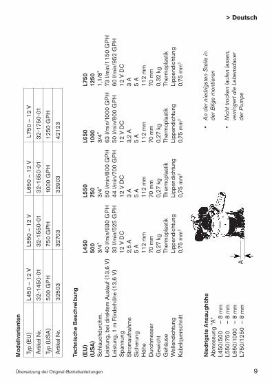
•Ande
rniedrigsten
Stellein
derB
ilgemon
tieren
•Nichttroc
kenlaufen
lassen
,
verring
ertd
ieLeb
ensd
auer
de
rPum
pe
Nie
drig
ste
Ans
augh
öhe
Abm
essu
ng "A
"L4
50/5
00
– 8
mm
L550
/750
–
8 m
mL6
50/1
000
– 8
mm
L750
/125
0 –
8 m
mA
Tech
nisc
he B
esch
reib
ung
(EU
) L4
50
L550
L6
50
L750
(U
SA
) 50
0 75
0 10
00
1250
Sch
lauc
hdur
chm
. 3/
4"
3/4"
3/
4"
1,1/
8"Le
istu
ng, b
ei d
irekt
em A
usla
uf (1
3,6
V)
40 l/
min
/630
GP
H
50 l/
min
/800
GP
H
63 l/
min
/100
0 G
PH
73
l/m
in/1
150
GP
HLe
istu
ng, 1
m F
örde
rhöh
e (1
3,6
V)
33 l/
min
/525
GP
H
44 l/
min
/700
GP
H
50 l/
min
/800
GP
H
60 l/
min
/952
GP
HS
pann
ung
12 V
DC
12
V D
C
12 V
DC
12
V D
CS
trom
aufn
ahm
e 2,
5 A
3
A
3,2
A
3 A
Sic
heru
ng
5 A
5
A
5 A
5
AH
öhe
112
mm
11
2 m
m
112
mm
11
2 m
mD
urch
mes
ser
70 m
m
70 m
m
70 m
m
70 m
mG
ewic
ht
0,27
kg
0,27
kg
0,27
kg
0,32
kg
Geh
äuse
Th
erm
opla
stik
Th
erm
opla
stik
Th
erm
opla
stik
Th
erm
opla
stik
Wel
lend
icht
ung
Lipp
endi
chtu
ng
Lipp
endi
chtu
ng
Lipp
endi
chtu
ng
Lipp
endi
chtu
ngKa
belq
uers
chni
tt 0,
75 m
m2
0,75
mm
2 0,
75 m
m2
0,75
mm
2
Mod
ellv
aria
nten
Typ
(EU
)L4
50 –
12
VL5
50 –
12
VL6
50 –
12
V L
750
– 12
V
Arti
kel N
r.32
-145
0-01
32-1
550-
01
32
-165
0-01
32-1
750-
01
Typ
(US
A)
500
GP
H75
0 G
PH
1000
GP
H12
50 G
PH
Arti
kel N
r.32
503
3270
332
903
4212
3

10 Übersetzung der Original-Betriebanleitungen
> Deutsch
EINBAU Bitte befolgen Sie diese Anweisungen, nur dann kann garantiert werden, daß die Pumpe einwandfrei und mit voller Leistung arbeitet.1. Die Pumpe an der niedrigsten
Stelle im Bilgenraum montieren. 2. Wählen Sie eine günstige
Stelle, wo das Bilgenwasser leicht überboard gepumpt werden kann, so hoch wie möglich über der Wasserlinie und den kürzesten Abstand zur Pumpe. Zu diesem Zweck soll ein 3/4 (L750/1250 – 1,1/8") Schottdurchgang angebracht werden.
3. Befestigen Sie eine brennstoffeste, 3/4" (L750/1250 – 1,1/8") Schlauchverbindung an dem Pumpenauslaß, das andere Endezum 3/4" Schottdurchgang. Der Schlauch sollte eine konstante Steigung haben.
Elektrische Anlagen1. Den braunen Leiter zur
positiven (+) Klemme der Batterie legen.
2. Den schwarzen Leiter zur negativen (-) Klemme der Batterie legen.
3. Die Isolierung so wenig wie möglich zurückschneiden und
alle Anschlüsse wohl über der Wasserfläche halten. Die elektrischen Verbindungen müssen auf sicherem Abstand über dem Hochwasserstand im Bilgenboden angebracht werden. Als Korrosionsschutz sollen die Leiter mit einer wasserfesten Dichtung geschützt werden. Isolierungen oder Kabelummantelungen müssen so zurückgeschnitten werden, daß die Isolierung oder Ummantelung in einem sicheren Abstand über dem Hochwasserstand endet.
Um die Treibeinheit zu entfernen oder ersätzenSieheSeite211. Die Zunge heben und die zwei
Flügeln gege Uhrzeigersinn drehen und aufheben.
2. Um wieder zu montieren, sich vergewissern dass die Dichtung richtig gelegen ist. Die Dichtung mit einem dünnen schicht vegetabi-lischer oder Mineralöl einschmieren, dann die zwei Kämme auf beiden Seite der Treibeinheit mit der zwei Ausspahrungen in der änssere Gehäuse einrichten. Herunterdrücken und im Uhrzeigersinn umdrehen. Um sich zu vergewissern dass die Treibeinheit richtig eingesetzt ist, die zwei Flügeln gegen

11Übersetzung der Original-Betriebanleitungen
> Deutsch
Den Niveauschalter AS888, die Schalttafel und die Sicherung immer zwischen der positiven (+) Klemme der Batterie und der positiven (+) Verbindung an der Pumpe (brauner Leiter) anschließen. Der negative (-) Leiter (schwarz) der Pumpe wird direkt an die negative (-) Klemme der Batterie gelegt. Der Nennstrom der Sicherung bezieht sich auf die Pumpenspezifikation.
Electronik-SchwimmerschalterArt. Nr. (EU) 34-1900 B – 12 V, 34-1900 B – 24 V (USA) 36152 – 12 V, 36252 – 24 V Der elektronische Schwimmerschalter ist der gleiche, wie an der Duo Patronenpumpe. Als separates Zubehör ist es möglich, diesen an alle SPX Johnson Pump Bilge-Pumpen der L-Serie zu befestigen.
Entsorgung/Recycling Nach Lebensdauerende entsorgen Sie die Pumpe nach den örtlichen Vorschriften. Nach Möglichkeit demontieren Sie Teile der Pumpe um sie dem Recycling-Process zuzuführen.
Uhrzeigersinn drehen, ohne die Zunge zu heben. Die Treibeinheit sollte sich nicht bewegen.
ZUBEHÖRAutomatischer Niveauschalter AS888Art. Nr. 34-888/26014 AS888 schützt elektrische Pumpen und bietet vollauto-ma-tischen Betrieb. Der AS888 Schalter ist aus korro-sionsfesten Materialien hergestellt.
Schalttafel 12 oder 24 VArt. Nr. (EU) 12 V – 34-1224, 24 V – 34-1225(USA) 12 V – 82044, 24 V– 82044-24 Die Schalttafel, zusammen mit dem Niveauschalter AS888 ist eine vorzügliche Kombination für Ihr Boot.
SPX Johnson Pump Tauchbilgenpumpe/Niveau-schalter AS888/SchalttafelSieheSeite22

12 Traduction du manuel d'instruction d'origine
> Français
•Installerlapo
mpe
aupo
int
leplusba
sde
lacale
•Pou
rune
pluslong
uedurée
deviedelapom
pe,n
epa
sla
faire
fonc
tionn
eràvide
Plus
bas
niv
eau
pour
la s
ucci
onM
esur
e "A
"L4
50/5
00
– 8
mm
L550
/750
–
8 m
mL6
50/1
000
– 8
mm
L750
/125
0 –
8 m
mA
Car
acté
ristiq
ues
tech
niqu
es
(EU
) L4
50
L550
L6
50
L750
(U
SA
) 50
0 75
0 10
00
1250
Dia
m. d
e tu
yau
19 m
m
19 m
m
19 m
m
28 m
mD
ébit,
refo
ulem
ent l
ibre
(13,
6 V)
40
l/m
in/6
30 G
PH
50
l/m
in/8
00 G
PH
63
l/m
in/1
000
GP
H
73 l/
min
/115
0 G
PH
Déb
it, re
foul
emen
t à 1
m (1
3,6
V)
33 l/
min
/525
GP
H
44 l/
min
/700
GP
H
50 l/
min
/800
GP
H
60 l/
min
/952
GP
HVo
ltage
12
V D
C
12 V
DC
12
V D
C
12 V
DC
Inte
nsité
2,
5 A
3
A
3,2
A
3 A
Fusi
ble
5 A
5
A
5 A
5
AH
aute
ur
112
mm
11
2 m
m
112
mm
11
2 m
mD
iam
. max
i 70
mm
70
mm
70
mm
70
mm
Poid
s 0,
27 k
g 0,
27 k
g 0,
27 k
g 0,
32 k
gC
orps
Th
erm
opla
stiq
ue
Ther
mop
last
ique
Th
erm
opla
stiq
ue
Ther
mop
last
ique
Etan
chéi
té
Join
t à lè
vres
Jo
int à
lèvr
es
Join
t à lè
vres
Jo
int à
lèvr
esS
ectio
n de
câb
les
0,75
mm
2 0,
75 m
m2
0,75
mm
2 0,
75 m
m2
Spé
cific
atio
ns d
u m
odèl
e
Mod
èle
(EU
)L4
50 –
12
VL5
50 –
12
VL6
50 –
12
V L
750
– 12
V
Réf
éren
ce32
-145
0-01
32-1
550-
01
32
-165
0-01
32-1
750-
01
Mod
èle
(US
A)
500
GP
H75
0 P
GH
1000
GP
H12
50 G
PH
Réf
éren
ce32
503
3270
332
903
4212
3

13Traduction du manuel d'instruction d'origine
> Français
INSTALLATIONSuivre méticuleusement les instructions ci-dessous afin d’obtenir un rendement optimum.1. Monter la pompe au point le
plus bas de la cale. 2. Choisir un endroit par lequel
les eaux de cale seront pompées et évacuées aussi haut que possible au-dessus de la ligne d’eau et le plus près possible de la pompe. Installer un raccord fileté de 19 mm (L750/1250 – 28 mm) à travers la coque.
3. Monter un tuyau résistant à l’essence de 19 mm (L750/1250 – 28 mm) entre la sortie de la pompe et le raccord fileté traversant la coque. Eviter les plis et les boucles. Fixer le tuyau si nécessaire. Important: Afin d’éviter les poches d’air, il est important de s’assurer que la sortie du tuyau ne soit pas dirigée vers le bas, mais toujours vers le haut.
Installation electrique1. Relier le fil marron à la borne
positive (+) de la batterie.2. Relier le fil noir à la borne
negative (-) de la batterie.3. Ne pas enlever la pelicule
isolatrice plus que nècessaire. Tous les branchements électriques doivent être placés au-dessus du niveau le plus
haut des eaux de cale. Toutes les connexions et les bornes doivent être isolées à l’aide d’un matériau etanche pour éviter toute corrosion. Le dénudage des câbles doit être fait de façon à ce que l’isolant ou le revêtement extérieur du câble soit bien au-dessus du niveau le plus haut des eaux de cale.
Pour enlever ou remplacer l'ensemble moteurVoirpage211. Soulever la languette et tourner
les deux oreilles dans le sens de rotation inverse à celui des aiguilles d'une montre.
2. Pour remonter, s'assurer d'abord que le joint est bien en place. Enduire le joint d'une mince couche d'huile végétale ou minérale, et aligner ensuite les deux tenons des deux côtés de l'ensemble moteur, avec les échancrures correspondantes du corps exterieur. Presser et tourner dans le sens de rotation des aiguilles d'une montre. Pour s'assurer que l'ensemble moteur est bien en place, tourner les oreilles dans le sens de rotation inverse à celui des aiguilles d'une montre, sans soulever la languette. L'ensemble moteur doit rester en place.

14 Traduction du manuel d'instruction d'origine
> Français
ACCESSOIRESInterrupteur automatique à flotteur AS888 Ref. No. 34-888/26014AS888 protège les pompes fonctionnant à l’électricité et offre un mode de fonctionnement entièrement automatique. Le AS888 est composé de matériaux résistants à la corrosion.
Tableau de commande 12 ou 24 VRef. No.(EU) 12 V – 34-122424 V – 34-1225(USA) 12 V – 82044, 24 V – 82044-24Avec un tableau de commande pour l’interrupteur AS888 vous aurez une installation parfaite pour votre bateau.
Pompe de cale submersible SPX Johnson Pump/Interrupteur à flotteur AS888/Tableau de commandeVoirpage22Toujours brancher l’interrupteur à flotteur AS888, le tableau de commande et les fusibles entre la borne positive (+) de la batterie et la borne positive (+) de la pompe (fil marron).
La borne négative (-) de la pompe doit être directement connectée à la borne négative (-) de la batterie. Le choix des fusibles se fait en fonction des spécifications de la pompe.
Contacteur de niveau électroniqueRef. No. (EU) 34-1900 B – 12 V 34-1900 B – 24 V (USA) 36152 – 12 V, 36252 – 24 V Le contacteur de niveau électronique est le même que sur les pompes à cartouche Duo. Il est fourni en tant qu´accessoire séparé et il est possible de l´accrocher sur les pompes SPX Johnson Pump series L.
Gestion des déchets/recyclage des matériauxLorsque le matériel arrivera en fin de vie, veuillez le mettre au rebut en fonction des lois applicables. Lorsque c'est possible, veuillez dé-monter le matériel et recycler les pièces pouvant l'être
15Traducción de instrucciones originales
> Español
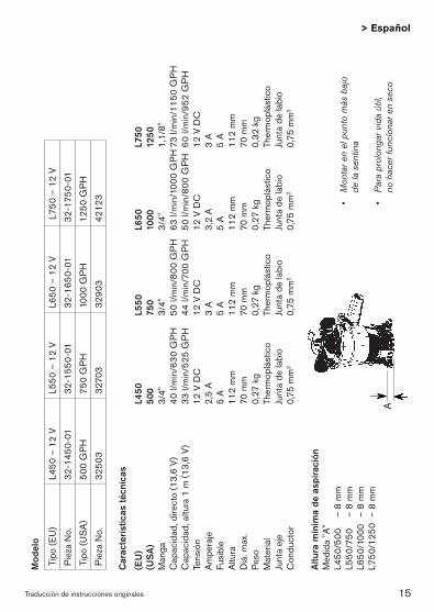
•Mon
tare
nelpun
tom
ásbajo
de
lasen
tina
•Paraprolon
garv
idaútil,
no
hac
erfu
ncíona
renseco
Altu
ra m
ínim
a de
asp
iraci
ónM
edid
a "A
"L4
50/5
00
– 8
mm
L550
/750
–
8 m
mL6
50/1
000
– 8
mm
L750
/125
0 –
8 m
m
A
Car
acte
rístic
as té
cnic
as
(EU
) L4
50
L550
L6
50
L750
(U
SA
) 50
0 75
0 10
00
1250
Man
ga
3/4"
3/
4"
3/4"
1,
1/8"
Cap
acid
ad, d
irect
o (1
3,6
V)
40 l/
min
/630
GP
H
50 l/
min
/800
GP
H
63 l/
min
/100
0 G
PH
73
l/min
/115
0 G
PH
Cap
acid
ad, a
ltura
1 m
(13,
6 V)
33
l/m
in/5
25 G
PH
44
l/m
in/7
00 G
PH
50
l/m
in/8
00 G
PH
60
l/min
/952
GP
HTe
nsió
n 12
V D
C
12 V
DC
12
V D
C
12 V
DC
Am
pera
je
2,5
A
3 A
3,
2 A
3
AFu
sibl
e 5
A
5 A
5
A
5 A
Altu
ra
112
mm
11
2 m
m
112
mm
11
2 m
mD
iá. m
ax.
70 m
m
70 m
m
70 m
m
70 m
mPe
so
0,27
kg
0,27
kg
0,27
kg
0,32
kg
Mat
eria
l Th
erm
oplá
stic
o Th
erm
oplá
stic
o Th
erm
oplá
stic
o Th
erm
oplá
stic
oJu
nta
eje
Junt
a de
labi
o Ju
nta
de la
bio
Junt
a de
labi
o Ju
nta
de la
bio
Con
duct
or
0,75
mm
2 0,
75 m
m2
0,75
mm
2 0,
75 m
m2
Mod
elo
Tipo
(EU
)L4
50 –
12
VL5
50 –
12
VL6
50 –
12
V L
750
– 12
V
Piez
a N
o.32
-145
0-01
32-1
550-
01
32
-165
0-01
32-1
750-
01
Tipo
(US
A)
500
GP
H75
0 G
PH
1000
GP
H12
50 G
PH
Piez
a N
o.32
503
3270
332
903
4212
3
16 Traducción de instrucciones originales
> Español
INSTALACIÓNSe recomienda observar estrictamente estas instruc-ciones de instalación para asegurar la mayor eficacia de la bomba de sentina.1. Montar la bomba en el punto
más bajo de la sentina. 2. Elegir un punto por el que
el agua de sentina se vaya a bombear fuera que esté lo más alejado posible de la línea de flotación y a la menor distancia de la bomba. Instalar un accesorio de 3/4" (L750/1250 – 1,1/8") atravesando el casco.
3. Fijar una manga de 3/4" (L750/1250 – 1,1/8") resistente al petróleo de la salida de la bomba al accesorio que atraviesa el casco. Evitar cocas y lazos. Si fuera necesario, apoyar la manga. Observación: para evitar la entrada de aire, es importante no dejar que la manga caiga por debajo de la salida de la bomba. La manga debe presentar una elevación constante.
Equipo eléctrico1. Conectar el conductor castaño
al borne positivo (+) de la batería.
2. Conectar el conductor negro al borne negativo (-) de la batería.
3. No quitar el aislamiento
mas que necesario. Todo el cableado debe quedar por encima del nivel màs alto de agua. Las conexiones deben sellarse con un compuesto para aplicaciones marinas a fin de evitar la corrosión de los cables. El materialaislante o camisa del cable debe separarse de tal modo que el aislante o camisa termine bien por encima del nivel más alto de agua de la sentina.
Para quitar o substituir la unidad motrizVerpágina211. Levantar la lengüeta y girar las
dos orejas en sentido contrario a lo de la rotación de las agujas del reloj, y sacar la unidad motriz.
2. Para montrar de nuevo, asegurarse que la junta estea en su sitio. Untar la junta de una capa menuda de aceite vegetal o mineral, y luego alinear los dos cames de los dos lados de la unidadmotriz con las dos muecas del cuerpo exterior. Apretar y girar en el sentido de rotación de las aguja del reloj. Para asegurarse que la unidad motriz estea bien en su sitio, girar las orejas en el sentido contrário a lo de la rotación de las agujas del reloj sin levantar la lengüeta. La unidad motriz suele quedarse en su sitio.
17Traducción de instrucciones originales
> Español
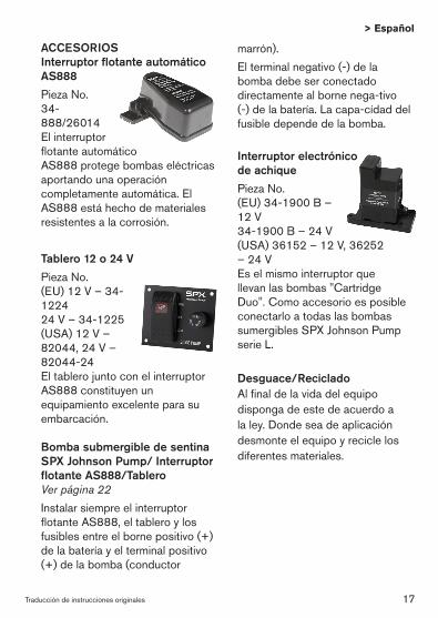
ACCESORIOSInterruptor flotante automático AS888 Pieza No. 34-888/26014El interruptor flotante automático AS888 protege bombas eléctricas aportando una operación completamente automática. El AS888 está hecho de materiales resistentes a la corrosión.
Tablero 12 o 24 VPieza No.(EU) 12 V – 34-122424 V – 34-1225 (USA) 12 V – 82044, 24 V – 82044-24El tablero junto con el interruptor AS888 constituyen un equipamiento excelente para su embarcación.
Bomba submergible de sentina SPX Johnson Pump/ Interruptor flotante AS888/TableroVerpágina22Instalar siempre el interruptor flotante AS888, el tablero y los fusibles entre el borne positivo (+) de la batería y el terminal positivo (+) de la bomba (conductor
marrón). El terminal negativo (-) de la bomba debe ser conectado directamente al borne nega-tivo (-) de la batería. La capa-cídad del fusible depende de la bomba.
Interruptor electrónico de achiquePieza No. (EU) 34-1900 B – 12 V 34-1900 B – 24 V (USA) 36152 – 12 V, 36252 – 24 V Es el mismo interruptor que llevan las bombas "Cartridge Duo". Como accesorio es posible conectarlo a todas las bombas sumergibles SPX Johnson Pump serie L.
Desguace/RecicladoAl final de la vida del equipo disponga de este de acuerdo a la ley. Donde sea de aplicación desmonte el equipo y recicle los diferentes materiales.

18 Traduzione delle istruzioni originali
> Italiano
•Mon
tarenelpun
topiùbasso
dellasen
tina
•Perprolung
arelavitadella
pompa
,evitarele
ope
razion
i
asecc
o
Live
llo p
iù b
asso
per
asp
irazi
one
Mis
ura
"A"
L450
/500
–
8 m
mL5
50/7
50
– 8
mm
L650
/100
0 –
8 m
mL7
50/1
250
– 8
mm
A
Car
atte
ristic
he te
cnic
he
(EU
) L4
50
L550
L6
50
L750
(U
SA
) 50
0 75
0 10
00
1250
Sez
ione
tubo
3/
4"
3/4"
3/
4"
1,1/
8"Po
rtata
mas
sim
a (1
3,6
V)
40 l/
min
/630
GP
H
50 l/
min
/800
GP
H 6
3 l/m
in/1
000
GP
H 7
3 l/m
in/1
150
GP
HPo
rtata
a 1
mt d
i pre
vale
nza
(13,
6 V)
33
l/m
in/5
25 G
PH
44
l/m
in/7
00 G
PH
50
l/m
in/8
00 G
PH
60
l/min
/952
GP
HVo
ltagg
io
12 V
DC
12
V D
C
12 V
DC
12
V D
CA
mpe
ragg
io
2,5
A
3 A
3,
2 A
3
AC
apac
ità fu
sibi
le
5 A
5
A
5 A
5
AA
ltezz
a 11
2 m
m
112
mm
11
2 m
m
112
mm
Dia
met
ro m
ax.
70 m
m
70 m
m
70 m
m
70 m
mPe
so
0,27
kg
0,27
kg
0,27
kg
0,32
kg
Cor
po
Term
opla
stic
o Th
erm
opla
stic
o Te
rmop
last
ico
Term
opla
stic
oG
uarn
izion
e al
bero
Ti
po "C
orte
co"
Tipo
"Cor
teco
" Ti
po "C
orte
co"
Tipo
"Cor
teco
"D
imen
sion
e ca
vo
0,75
mm
2 0,
75 m
m2
0,75
mm
2 0,
75 m
m2
Spe
cific
a de
l tip
o
Tipo
(EU
)L4
50 –
12
VL5
50 –
12
VL6
50 –
12
V L
750
– 12
V
Art.
No.
32-1
450-
0132
-155
0-01
32-1
650-
0132
-175
0-01
Tipo
(US
A)
500
GP
H75
0 G
PH
1000
GP
H12
50 G
PH
Art.
No.
3250
332
703
3290
342
123

19Traduzione delle istruzioni originali
> Italiano
INSTALLAZIONE Si prega di seguire con attezione le istruzioni di montaggio per garantire la massima efficacia di funzionamento alla vostra pompa di sentina.1. Montare la pompa nel punto più
basso della sentina. 2. Scegliere il punto da cui l’acqua
di sentina deve essere pompata fuori bordo, il più alto possibile rispetto alla linea d’acqua ed alla minima distanza dalla pompa. Installare un attacco di 3/4" (L750/1250 – 1,1/8") attraverso la carena.
3. Collegare un tubo di 3/4" (L750/1250 – 1,1/8") resistente ai carburanti dalla mandata della pompa all’attacco a carena. Evitare curve brusche o occhielli. Se necssario, supportare il tubo. Nota: per prevenire bolle d’aria é importante che il tubo non si immerga al di sotto della mandata della pompa. Il tubo dovrebbe essere costantemente sollevato.
Installazione elettrica1. Collegare il cavo elettrico
marrone al terminale positivo (+) della batteria.
2. Collegare il cavo elettrico nero al terminale negativo (-) della batteria.
3. Non rimuovere il isolamento più che necessario. Tutti i collegamenti elettrici devonoessere posti al di sopra del livello più alto dell’acqua. I collegamenti ed i cavi devono essere sigillati con un sigillante marino per prevenire la corrosione. L’isolamento o la guaina del cavo devono essere rimossi in modo tale che l’isolamento o la guaina terminino ben al di sopra del livello più alto dell’acqua di sentina.
Per rimuovere o sostiture l'unità motriceVedipágina211. Levare la linguetta e girare le
due ali in senso antiorario e sollevarel'unità motrice.
2. Per rimontare, in primo luogo assicurarsi che la guarnizione sai in luogo. Ungere la guarnizione con una pellicola di oleo vegetale o minerale, dopo alineare le due came da tutti e due i lati dell'unità motrice con le due tacche del corpo esteriore. Opprimere e girare in senso orario. Per assicurarsi che l'unità motrice sai in luogo, girare le ali in senso antiorario sensa sollevare la linguetta. L'unità motrice doverà rimanere in luogo.

20 Traduzione delle istruzioni originali
> Italiano
ACCESSORIInterruttore Automatico galleggiante AS888
Art. Nr. 34-888/26014AS888 protegge le pompe a funzionamento elettrico ed automatizza completamente le operazioni. AS888 é prodotto usando materiali resistenti alla corrosione.
Pannello 12 o 24 VArt. Nr.(EU) 12 V – 34-1224 24 V – 34-1225 (USA) 12 V – 82044, 24 V – 82044-24Il pannello combinato con l’interruttore AS888 garantisce una eccellente installazione per la vostra barca
Pompa di sentina sommersa/Interruttore galleggiante AS888/ PannelloVedipágina22 Installare sempre l’interruttore galleggiante AS888, il pannello ed i fusibili tra il terminale positivo (+) della batteria ed il collegamento positivo (+) della pompa (cavo marrone).
Il collegamento negativo (-) (cavo nero) della pompa deve essere collegato direttamente al terminale negativo (-) della batteria. La capacità del fusibile é determinata dalla specifica della pompa.
Interruttore elettronico di livelloArt. Nr. (EU) 34-1900 B – 12 V 34-1900 B – 24 V(USA) 36152 – 12 V, 36252 – 24 V Questo interruttore elettronico di livello è lo stesso che viene montato sulle pompe di sentina Duo. Può essere montato su tutte le pompe SPX Johnson Pump serie L come accessorio separato.
Gestione dei rifiuti/ riciclaggio dei materialiAl termine della vita del prodotto si prega di smaltire il prodotto secondo le leggi in vigore per queste operazioni. Quando possibile, si raccomanda di smontare il prodotto e riciclare i materiali dei componenti.

21
LyftlåshakenLifttabDieZungehebenSouleverlalanguetteLevantarlalengüetaLevarelalinguetta
MonteraReinstallMontierenRemonterMontrarRimontare
DemonteraRemoveEntfernenEnleverQuitarRimuovere
TätningSealDichtungJointJuntaGuarnizione

22
Elektrisk intsallation med panelElectrical installation with PanelElektrischer Anschluss mit SchalttafelSchéma de raccordement avec le tableau de commandeInstalación eléctrica con panelSchema collegamento elettrico con pannello di controllo
DCsup
ply•B
atterie
DC
-Ver
sorg
ung
B
atteria
•Batería
Bat
teri
B
row
n
Mar
ron
B
raun
M
arro
ne
Mar
rón
B
run
Aut
omat
ic S
witc
h AS
888
(+) b
row
n pu
mp
lead
(+
) fil m
arro
n de
la p
ompe
(+) b
raun
er P
umpe
leite
r(+
) pom
pa c
avo
mar
rone
(+) c
ondu
ctor
bom
ba m
arró
n(+
) bru
n pu
mpk
abel
(-) b
lack
pum
p le
ad(-
) fil n
oir d
e la
pom
pe(-
) sch
war
zer P
umpe
leite
r(-
) pom
pa c
avo
nero
(-) c
ondu
ctor
bom
ba n
egro
(-) s
vart
pum
pkab
el
2 B
ilge
pum
p
Pom
pe d
e ca
le
B
ilgen
pum
pe
Pom
pa d
i sen
tina
B
omba
de
sent
ina
Lä
nspu
mp
Not
e: T
his
cabl
e is
alre
ady
conn
ecte
dIm
port
ant:
Ce
câbl
e es
t déj
à co
nnec
téW
icht
ig: K
abel
ist b
erei
ts v
erbu
nden
Not
a B
ene:
Que
sto
cavo
é g
ià c
olle
gato
Adv
erte
ncia
: Est
e ca
ble
ya e
stá
cone
ctad
oO
bs: D
enna
kab
el ä
r red
an a
nslu
ten
1 Pa
nel
Ta
blea
u de
com
man
de
Sch
altta
fel
Pa
nnel
lo
Tabl
ero
Pa
nel

23
Elektrisk intsallation utan panelElectrical installation without panelElektrischer Anschluss ohne SchalttafelSchéma de raccordement sans tableau de commandeInstalación eléctrica sin panelSchema collegamento elettrico senza pannello di controllo
1. Länspump Bilge pump Bilgenpumpe Pompe de cale Bomba de sentina Pompa di sentina
(-) svart pumpkabel(-) black pump lead(-) schwarzer Pumpeleiter(-) fil noir de la pompe(-) conductor bomba negro(-) pompa cavo nero
(+) brun pumpkabel (+) brown pump lead (+) brauner Pumpeleiter (+) fil marron de la pompe (+) conductor bomba marrón(+) pompa cavo marrone
Johnson Pump Automatic Switch AS888
Batteri•DCsupply DC-Versorgung Batterie•Bateria
DCsupply•Batterie DC-Versorgung Batteria•Batería Batteri

JOHNSON PUMPS OF AMERICA INC.
1625 Hunter Road, Suite B,
Hanover Park, Illinois, 60133, USA
P: +1 847 671 7867
F: +1 847 671 7909
E: [email protected] S PX FLOW TECH NOLOGY SWE D E N AB
Nastagatan 19, P.O. Box 1436
SE-701 14 Örebro, Sweden
P: +46 (0)19 21 83 00
F: +46 (0)19 27 23 72
SPX reserves the right to incorporate our latest design and material
changes without notice or obligation. Design features, materials of
construction and dimensionals data, as described in this bulletin, are
provided for your information only and should not be relied upon unless
confirmed in writing.
Please contact your local sales representative for product availability in
your region. For more information visit www.spx.com.
ISSUED 02/2012 IB-103 R05
COPYRIGHT ©2012 SPX Corporation
Submersible Bilge Pumps CARTR I DG E L-S E R I E S L450, L550,
L650, L750