Embed Size (px)
Citation preview

g A~R \E VV\._ S c. H u!)o1Cl't,_
@[f)~OOC-\ tr a@~~ tr~~tr lf)(b~~
lF©OO
tr [M) rn ~ [Ml oo © (!JJ@ © [f tr (!lJ [fa a [M
oo v ~lbrn~troo © ~ £@j ~ rn tr a~ oo £@a£ 11 a©rrJ
£ 11 w £ oo a@ M $ w £ w ~ lb~rrJ@ 11~ $

OPERATIONS TEST PLAN
FOR
FOR INVESTIGATING THE SHROUD OF TURIN
BY
ELECTROMAGNETIC RADIATION AT VARIOUS WAVELENGTHS
Prepared by
The Shroud of Turin Research Project, Inc.
In conjuction with
The Holy Shroud Guild
Copyright 1978
by
The Shroud of Turin Research Project, Inc.
CONFIDENTIAL - NOT FOR PUBLIC RELEASE
•

Introduction
In 1969 and again in 1973, selected scientists and scholars,
at the invitation of authorities in Turin, made a preliminary exam
ination of the Shroud of Turin . Their report, released in 1975,
was the first organized attempt in scientific research on the
Shroud relic . This investigation represented a major advance
in the understanding of the Shroud, for not only did it bring
to light new discoveries, but it also paved the way for further
research. All over the worla, including the United States, new
interest and enthusiasm for more research had been stimulated
by the bold step made in Turin almost one decade ago .
Only several months after the release of Turin 's scienti
fic commission report, a conference on the Shroud was held in
Albuquerque, New Mexico (March 23 and 24, 1977) to determine
what we in the United States might offer towards furthering
the understanding of the Shroud. We concluded that only non
destructive tests should be performed and therefore, on Septem
ber 19, 1977, a delegation of scientists met with the Inter
national Center of Sindonology in Turin to present our ideas
in the form of a written proposal and two published volumes
of the proceedings of the Albuquerque Conference.
On April 26 , 1978, we received word through Father Rinaldi
that we should begin preparing our tests for October, 1978,
at the time of the World Congress and Exposition of the Shroud.
On June 3 and 4, 1978, the team of scientists met with Father
2

Introduction (cont.)
Page 2
Rinaldi in Colorado Springs and formulated a plan by which all
t est procedures, procurement of test equipment , and financial
preparations would be made in time for October. On September
3 and 4, . 1978, a dry run of all test procedures was successfuJJy
completed in Amston> Connecticut. And on September 29, 1978,
the scientific team departed for Turin. It goes without sayin~
that the entire team is grateful to the Turin authorities f or
this opportunity to obtain and share scientific data on the
Shroud.
This operations plan represents the fruit of all these
labors. It has been designed so that our study of the Shroud
can occur with the maximum amount of efficiency in the minimum
amount of time.
3

GENERAL REMARKS IN THE USE OF THIS OPERATIONS PLAN
1. All team members should be familiar with the entire
t~st plan prior to Monday, October 2, so that he (she)
can best integrate their efforts into the overall effort.
2 . The Operations Plan is organized into the f ollowing
sections:
a. General remarks by Team Coordinators.
b . Description of the Grid Coordinat• System to be
used by all team members .
c. Photograph of Shroud (front and back) with test
locations indicated.
d . List of Experimental Groups and Member s .
e. General Test Plan Organization.
f . Specific Test Plan Descriptions.
g. Individual Planning Calendar
3 . Blank pages have been deliberately placed into the
Operations Plan for the convenience of taking notes or
making last minute alterations.
4. Please write your name on the upper right hand corner of
the cover sheet of this book for easy identification if
misplaced .
5. Please bring any inaccuracies in the Operations Plan to
the immediate attention of the Team Coordinators, Eric
Jumper or John Jackson.
4

General Remarks by Team Coordinators
Because of certain sensitivities of Turin and so as to
not jeopardize the success of anyone's tests, all team members
are asked to observe the following guidelines while in Turin.
1. Immediately upon arrival in Turin, press contacts are
expected to be heavy. All team members are strongly
requested to refrain from discussing _anything regard
ing the tests and to kindly direct the press to Ken
Stevenson. While in principle our tests are approved,
final approval has been withheld pending discussions
of Turin witb our scientists, examination of our equip
ment and test procedures. We anticipate no problems,
but please do not complicate our situation by granting
interviews with the press or even give '·'innocent"
information to reporters of any kind. Reporters can add
two and two and come up with four as well as anyone .
2. Please do not show or discuss this operations plan to
any unauthorized person.
3, Any probl_ems of any kind should be directed immediately
to the appropr iate test group coordinator or to the
team coordinators, John Jackson and Eric Jumper .
Limited amounts of time require that all problems be
solved as quickly as possible .
4. Discussions with Turin will be handled via the Holy
Shroud Guild since this is the only body which the
5
General Remarks (cont.)
Page 2
Tur in authorities know or recognize. A warm relation
ship with Turin has been developed by the Holy Shroud
Guild over the past 25 years. Of course, no agreements
will be made with Turin without the full knowledge and
consent of the appropriate team members. Therefore, no
team member need or should take it upon him (her)self to
discuss specific problems with authorities in turin .
5. All team members should avoid giving the impression that
uthe Americans have landed". Turin is very sensitive to
this unfortunate American stereotype and this will be
complicated by the fact that we are a large American group.
Turin is the host and we are the guests .
6 . While all of us are interested in seeing the sights of
Turin and Europe , let us remember that our only reason
for being in Turin is the Shroud . Thus, we should all
ar~ange our schedules accordingly. (We an ticipate that
the first week, Monday through Friday, i.e. October 2 and
6 ,will be used in negotiations, setting up and dry run
ning experiments ; Saturday and Sunday i . e. October 7 and
8, the World Congress~ and Monday i . e . October 9 through
12, testing.)
Perhaps these seem restricting , but we , the team coordina
tors, strongly believe that these are the necessary minimum for
ensuring a successful test program in Turin. Accordingly, we wish
all the team members success and we stand eager to help you in
whatever way we can.
6

Coordinate System
It is important that all experiments, while referenced to
the same 20 x 20cm coordinate grid attached to the test frame , use
the same system of coordinates which is described herein.
The system will be Cartesian with the origin at the lower left
hand corner as one normally looks at the Shroud mounted in t he test
frame. The y-axis is vertical, the x-axis horizontal. General
coordinate labels will be marked on the Shroud frame while Specific
(highly resolved) labels marked on the movable coordinate grid.
To minimize error, letters will be used as General coordinate:
labels for the y-axis and numerals for the General coordinate
labels of the x-axis. Numerals will be used, however, for both the
x and y axes of the Specific coordinates on the moveable grid.
Thus , as illustrated in the accompanying figure, the General coor-
dinates designate the particular 20 x 20cm square, while the
Specific coordinates designate the location of the point in ques-
tion within that square . The notation to be used is shown for
several points of the accompanying figure.
The locations of these points are written as follows:
specific x specific y coord in tm coord in
J cm
For point a <4,(15.0, ~10.0) General General x-coord. y-coord.
point b (3/10,0, E/5.0)
point c '. (4/20 . 0, B/10.0) or (5/0 . 0 , B/10,0)
point d (5/10.0, C/P.O.O) or (5/10.0,D/ O~O)
point e (7/20.0, B/20,0) or (8/.0.0 , B/20, O) or (7 /20 . 0, C/O. O) or (8/0.0, C/0,0)
7

Coordinate System (cont.)
Page 2
Note that in some cases , there is an ambigui ty as to nota
tion, but these ambiguities are easily recognized by the appear ance
of O. O or 20 . 0 anywhere in the notation. All numbers shall be
recorded to the neares t tenth of a centimeter (millimeter). All
photo d_pcµmentation should photograph this coordinate system and
use this notation.
8

~ w E-1 E-1 < p..,
Cl 1-1 IZ (.!)
w E-1 g 0 x @
.... p., p., <
9

Preselected Examination Points
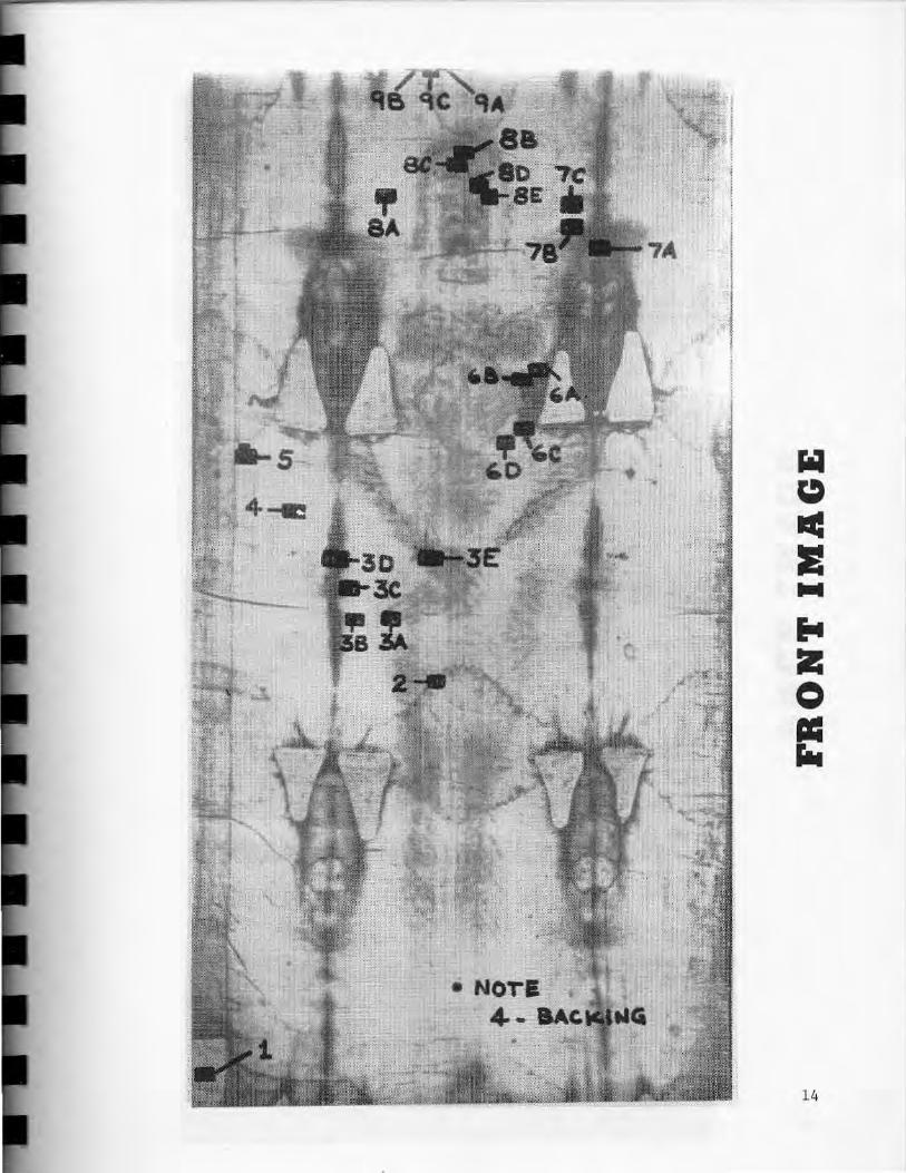
The points selected are shown on the attached Figures labeled
FRONT IMAGE and BACK IMAGE. All points are labeled starting from
l on the front image and also starting from 1 on the back image;
therefore , when refering to locations they should be refered to as
FRONT 3A (or F3A) when refering to the fingers for example or BACK
lE (or IllE) for the ankle area .
The locations were carefully chosen in groups so that the change
in reflectivity between the types of Shroud image can be compared.
Each group has a spot in a clear area for control, a spot i n a "blood"
stain area, a spot in the body image area, and a spot in a scorched area .
Note , for example, such groupings in the hand-wrist area on the front
image and the foot and side area in the back image . Additional locations
include spots on serum area, water marks and on the repair and backing
cloths.
The description of the location points is as follows :
FRONT IMAGE
(identification number)
(1) Edge-Strip patch near bottom
(2) Thigh-level water mark
(3) Hand group a . Middle finger image b . Control c. Light scorch to match density d. Dark scorch e. Blood on wrist
(4) Control below patch outside scorch area
10

(S) Red spot near patch
(6) Lance thrust group a. Intersection , blood/scorch b. Dark blood, lance entrance c. Serum area d. Control
(7) Scorch above patches a . Dark b. Light c . Control
(8) Face group a . Control outside face image near hair on way to left
patch b. "3" mark, light part c. "3" mark, dark part d . right eye e. right cheek
(9) Wet/Dry controls above head a. Inside water mark b. Outside water mark c. At margin
BACK IMAGE
(identification number)
(1 ) Foot group a . Blood Flow b. Control near flow c. Scorch on same level to match density d. Heel of foot e. Calf/Ankle image area (non-contact)
(2) Side str~p a . Side strip near seam (near old burn marks) b. Main cloth near seam
(3) Blood flow from side (near patch) a. Control b . Serum c. Blood d. Light- colored patch
(4) Scorch/Image intersection a. Heavy scorch
11

b. Light scorch in line c. Intersection in line d. Shoulder image (free of blood)
. (5) Holland cioth backing
ADDITIONAL POINTS OF INTEREST NOT SHOWN ON EITHER THE FRONT OR BACK
(1) Dust from casket
(2) Spectrum after pull tape
(3) Right side of neck image-dry
(4) Calf blood/image-dry
The following areas are requested from the visible spectra equipment
in support of the photographic experiment. Many of these are already
labeled for testing.
1. Blood (3 or 4 measurements) Foot (rear, off body) Wrist (at wound) Head wound ("3" mark) Scourge mark on back
2. Body (6 measurements) Cheek (unbruised) Hand (right hand fingers) Off calf of back image Right low intensity image of c lavical area Chest (off center right; above blood, high intensity area) Left Thigh (below right hand; low intensity area)
3. Lightly scorched area same intensity as corresponding body Measurement (3 measurements) Near head measurement Near back off calf measurement Near hand measurement -.
4. Background (3 to 4 measurements) Head left Head right Near hand Anywhere on back image
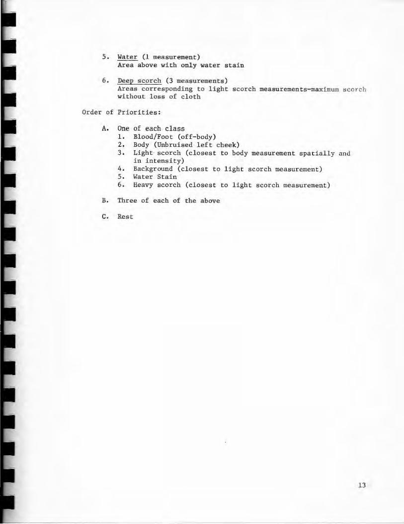
5. Water (1 measurement) Area above with only water stain
6. Deep scorch (3 measurements) Areas corresponding to light scorch measurements- maximum scorch without loss of cloth
Order of Priorities:
A. One of each cl ass 1. Blood/Foot (off-body) 2. Body (Unbruised l eft cheek) 3. Light- scorch (closest to body measurement spatially and
in intensity) 4. Background (closest to light scorch measurement) 5 . Water Stain 6. Heavy scorch (closest to light scorch measurement)
B. Three of each of the above
c. Rest
13
14

....
15

COMPOSITION OF UNI TED STATES RESEARCH TEAM
Teams:
1. Coordination
(J John Jackson - Co- coordinator
© Eric Jumper - Co-coordinator
2. Support
<::ff) Tom D' Muhala - Logistics Support Coordinator
~ Rudy Dichtl - Electronic Equipment Maintenance Specialist
~ Dee German - Electronic Equipment Maintenance Specialist
~ Tom Dolle - Logistic Support Technician
<:lJ Kay Jackson - Logistic Support Technician
~ Marge Jumper - Logistic Support Technician
~ Mary Stevenson - Logistic Support Technician
~Patsy German - Logistic Support Technician
<J:Z:) Joan Dichtl - Logistic Support Technician
3. Photographic I Computer Analysis and Enhancement
Don Devan - Photographic Test Coordinator
Don Lynn - Photographic Computer Analysis and Enhancement Specialist
Jean Lorre - Photographic Computer Analysis and Enhancement Specialist
Don Janney - Photographic Computer Analysis and Enhancement Specialist
Vern Miller - Head Photographer
Mark Evans - Assistant Photographer
Sam Pellicori - Optical Engineer
Barrie Schwartz - Documenting Photographer
4. Tape Sample Analysis
Ray Rogers - Tape Sample Analysis Coordinato'r and Chemical Consultant
Bob Dinegar - Chemical Consultant 16
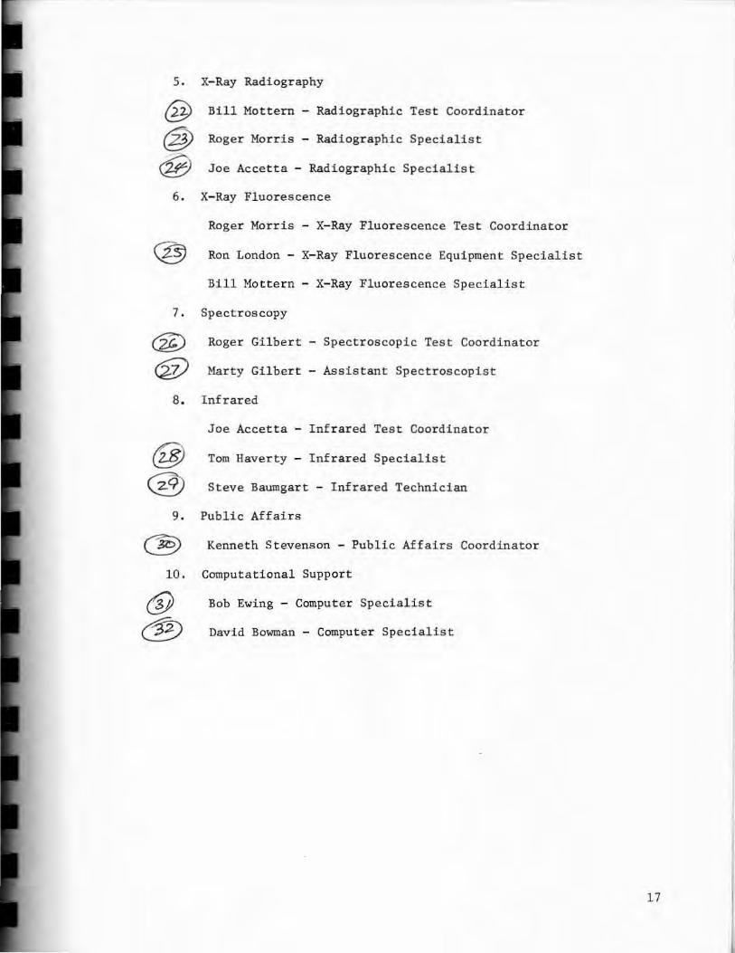
5. X-Ray Radiography
~ Bill Mottern - Radiographic Test Coordinator
~ Roger Mor ris - Radiographic Specialist
~ Joe Accetta - Radiographic Specialist
6. X- Ray Fluorescence
Roger Morris - X- Ray Fluorescence Test Coordinator
Ron London - X- Ray Fluorescence Equipment Specialist
Bill Motter n - X- Ray Fluorescence Specialist
7 . Spectroscopy
~ Roger Gilbert - Spectroscopic Test Coordinator
~ Marty Gilbert - Assistant Spectroscopist
8. Inf rared
Joe Accetta - Infrared Test Coordinator
~ Tom Haverty - Inf rared Specialist
~ Steve Baumgart - Infrared Technician
9. Public Affair s
~ Kenneth St evenson - Public Affairs Coordinator
10. Computationa l Support
<:Y Bob Ewing - Computer Specialist
~ David Bowman - Computer Specialist
17

The General Test Plan
The following table indicates the order in which the tests will
proceed. (Notifications of any changes will be given as soon as
possibl e.) The time for doing these tests has been allocated in the
basic units of hours. In all cases, the amount of time allocated is
slightly greater than or equal to the actual time indicated in the
Special Test Plan descriptions . Setup and breakdown times (as indica
in the Special Tes t Plan) sometimes overlaps with the time allocated
to other experiments. In that case . coordination should be made
between adjacent groups where overlap must occur.
As time is expended by each test gr oup, the hours may be checked
off. Should it be necessary to rearrange the ordering of some tests,
the hour numbers associated wi t h the interchanged tests will remain
the same and therefore the hour number s will be checked off as they
are accomplished . For example, suppose X-Ray Radiography (Block 2)
and Photography (Block 2) were for some reason interchanged . This
would only mean that hours 28-33 would be performed before hours 21-
27 . If an experiment were lengthened, we would consider the l ast hour
as being repeated several times; if one is shortened , the remaining
hours would be automatically be checked off . For example, if X-Ray
Radiography (Block 1) were given two extra hours, rather than try to
shift all subsequent experiments down two hours , we would simply re
peat hour 8 twice and annotate t he test plan accordingly. If X- Ray
Fluorescence (Block 3) was finished 3 hours early , hours 70, 71, and
72 would automatically be checked off and an indication that this was
done recorded on the test plan. Prior to testing , a system will be
arranged so that those not involved in a particular test will know
18

what time it is according to our "General Test Plan Clock." The team
coordinators, Eric and John will always have the "correct time."
However, all experimentors should plan on being given only the
time allocated and at the time indicated unless advised otherwise by
Eric or John. No one should, therefore, automatically assume that
additional time will be given, for it is imperative that all groups be
given a fair chance to collect data during the time constraints by
which we must operate. However, it should be pointed out that 15 hours
may be utilized at the end of the testing (under the direction of the
team coordinators.)
Turin authorities have determined that only those necessary for
a given test will be allowed in the test room at any given time . The
number of personnel required from our team is therefore indicated on
the General Test Plan. This isn 't meant to get us into a "numbers game" ,
but to serve as a reminder that access to the testing room is a sensi t i ve
issue with Turin.
Finally, we should expect to work round the clock so as not to leave
the Shroud in "suspended annimation". Notice that we will have compressed
over two 40 hour work weeks into the span of only 96 hours by the 4ime we
are finished .
19

Hour
Begin 1 2 3 4 5 6 7 8 9
10 11 12 13 14 15 16 17 18 19 20 21 22 23 24 25 26 27 28 29 30 31 32 33 34 35 36 37 38 39 40 41 42 43 44 45 46 47 48
GENERAL TEST PLAN
Test Group Number
Personnel Required
Photography 8 (Block 1)
X- Ray Radiography 7 (Block 1)
X-Ray Fluorescence 6 (Block 1)
Infrared (Block 1) 6
Spectroscopy (Block 1)
Infrared (Block 2) 10
Tape (Block 1)
X-Ray Radiography 7 (Block 2)
Photography 8 (Block 2)
X-Ray Fluorescence 6 (Block 2)
Infrared 6 (Block 3)
Infrared 6 (Block 4)
Time Allocated
Hours
6
2
4
1
7
7
6
10
2
3
Remarks
4 1/2 hours photo- mosiac
1 1/2 hours spectral coverage Preliminary test exposures ·taken
foot bl ood
I - R Photos test expesure
Infrared reflectance follows Spectroscopy (reflectance and UV fluorescence) location by location Tape samples collected.
Complete X- Ray Radiographic coverage
3 1/2 hour close- up
2 1/2 hour spectral coverage
Fingers and Face blood
Thermographic test exposures
Inf rared photographs
20

Hour
Continued 49 ·SO 51 52 53 54 55 56 57 58 59 60 61 62 63 64 65 66 67 68 69 70 71 72 73 74 75 76 77 78 79 80 81 82 83 84 85 86 87 88 89 90 91 92 93 94 95 96
GENERAL TEST PLAN
Number Time Test Group Personnel
Required
Spectroscopy (Block 2)
I nfrared (Block 5) 10
Tape (Block 2)
Photography 8 (Block 3)
X-Ray Fluorescence 6 (Block 3)
Infrared (Block 6)
To be determined based on results obtained
6
Allocated Hours
7
6
11
9
15
Remarks
Infrared reflectance follows spectroscopy (ref l ectance and UV fluorescence) location by location Tape samples collected
Microphotographs Stereophotogtaphs Rear Surface Photographs ( 2 hours apiece)
Face scan and watermarks
Other areas as time permits
Thermography
average number of United States scientists around Shroud= 7.25 ± 1.50
21
N N
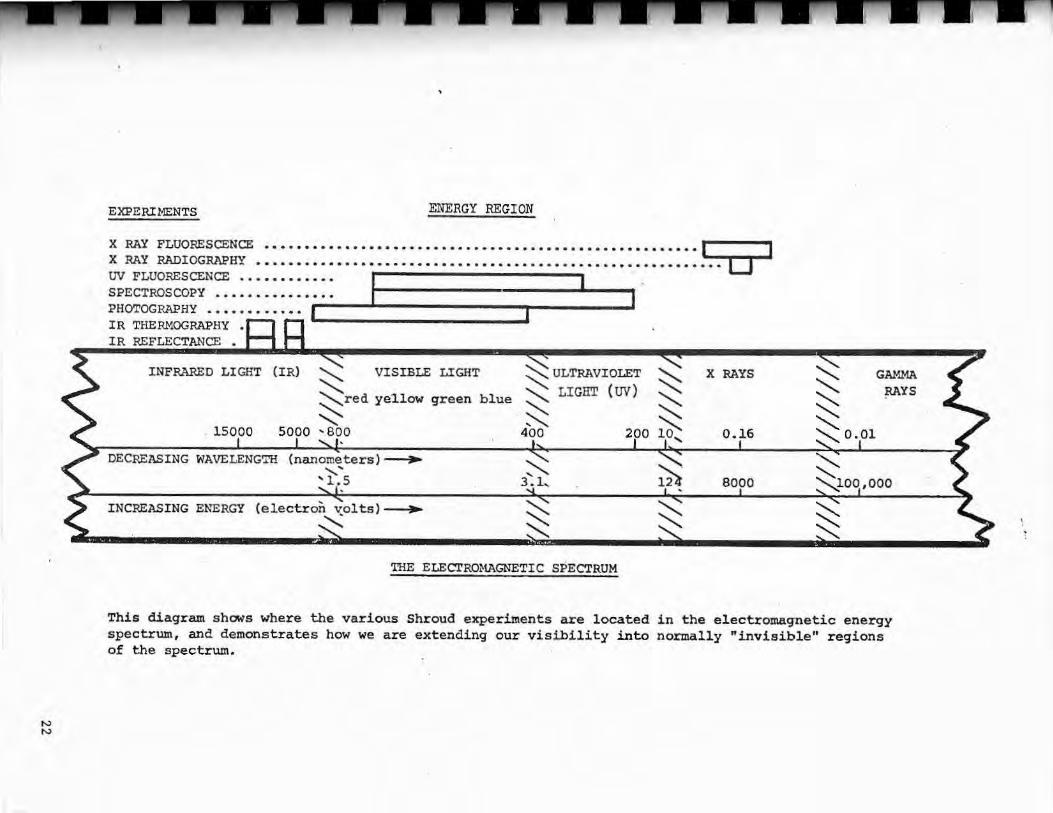
EXPERIMENTS ENERGY REGION
x RAY FLUO!mSc::E!NCE! •••• • • ••••••••• •• •••••••••••• •• •• • •• ••• ••• • • •••••••••• I I X RAY RADIOGRAPHY ••••••••••••••••••• • ••• • •• • • • • • • • • • • • • • • • • • • • • • • • • • • • • • • • • 0 UV FLUORESCENCE .. • • • • • • • • • • I I SPECTROSCOPY............... I PHOTOGRAPHY •••••••••••• I I IR THERMOGRAPHY • ,........ ,_, IR REFLECTANCE •
INFRARED LIGHT ~ VISIBLE LIGHT ~ULTRAVIOLET ~ '· LIGHT (UV) :::::--=red ye1low green blue ~ ""' . ~ '800 400 200 . 15000 5000
DECREASING WAVELENGTH (nanometers)~ ,~:s ~
3.l,
INCREASING ENERGY (electron volts)~ ~
:-.:::: ~
THE ELECTROMAGNETIC SPECTRUM
~ ~ :::---.:: ~ .....
~ '
~ ~
X RAYS
0.16
8000
~
~ ~ ~0.01
GAMMA RAYS
:-..:: ~lOQ,000 ~ ~
This diagram shows where the various Shroud experiments are located in the electromagnetic energy spectrum, and demonstrates how we are extending our visibility into nonnally "invisible" regions of the spectrum.

TEST PLAN FOR: ELECTRnNIC MAINTENANCE
GROUP COORDTNATOR: J . DEE GERMAN
TEAM MEMBERS : PATSY S. GERMAN
RUDOLPH J. DICHTL
JOAN L. DICHTL
BACKGROUND AND BASIC THEORY:
To ensure that all groups are supplied with prooer power
and to maintain all equipment in good working order .
BASIC PLAN:
1 . Upon arrival, Rudy, Joan, and an I talian electrician will
get the Elgar power supplies hooked up and working. Available
power will consist of :
a . 220-volt, single phase, 14-amp, 60 cycle (i.e.Standard
American 220) and 115-vnlt, single phase, 14-amp,
60 cycle (Standard American 115) power anywhere in the
test room.
b . 230-volt, s-tngle phase, 7-amp, 50 cycle "dirty"
(Standard Italian wall outlet) power in room.
c. Two separate 115-volt American circuits in set-up
rnom for equipment check-out and repair.
2 . Rudy, Joan, Dee and Patsy (Starting Oct. S) will be
available for general electrical/electronic set-up, repair and
parts procurement.
23
Test plan for Electronic Maintenance
Page 2
SPECIAL NEEDS:
Besides the aforement~oned electrical power, we need:
1. A room as close to the Shroud test room as possible, on
the same floor level, with 2 standard European electrical wall
outlets for equipment set-up and repair. This room should have
a cot .
2. We need to be able to reach someone who knows where to
obtain electrical/electronic parts; preferably someone who speaks
English .
24

TEST PLAN FOR: PHOTOGRAPHY
GROUP COORDINATOR: DON DEVAN
TEAM MEMBERS: DONALD J. LYNN
JEAN J , LORRE
VERNON MILLER
BARRIE M. SCHWARTZ
ERNEST H. BROOKS, II
MARK EVANS
SAM PELLICORI
BACKGROUND AND BASIC THEORY:
Three major photographic experiments will be performed:
(1) Photomosaic coverage (5.6:1 reduction) will cover the
entire Shroud with enough spatial detail to permit computer
weave removal and detailed feature analysis. Filtration will
be : (a) blue/green/red color separation; (b) UV-reflected for
contrast enhancement; (c) UV-transmission over light sources/
UV-blocking over lens for UV-fluorescence. Film: Kodak S0-115;
camera/lens: Hasselblad/150mm; lights: Norman 200 strobes (2
units providing crossed-field illwnination).
(2) Photomacro/micrography. Photomacrography will provide
approximately 3:1 enlargement of specific areas of interest so
that details of fibers can be seen. S0-115 film will permit
total enlargements on the order of lOOX. Filtration will be gels
(blue or green) over Sun-Pak strobes to provide contrast enhance
ment. Camera/lens : Beseler TOPCON/TOPCOR (microscope objective).
Micrography will be obtained with Wil d microscope with 35mm camera
attachment .
25
Test plan for Photography
Page 2
(3) Spectrally-resolved quad-mosaic photography(,..,, 22~
reduction - each image will cover a 4'x: 4' region on the Shroud).
Filtration will be: (1) B/G/R color separation; (2) narrow band
( "" 100 A0) spaced over visible spectrum; (3) unfiltered.
(4) Miscellaneous coverages: (a) portable digital spec~
trometer readings of features of interest using a circularly
variable interference filter spectrometer with a silicon photo
diode sensor and digital volt meter readout. (b) Binocular
(opthalmic) microsc~pe (10-100 X) for visual examination.
(c) Stereo imaging system for analysis of directional dependence
of Shroud coloration. (d) Fiber optics examination and photo~
graphy of rear surface of Shroud.
26

TOTAL HOURS
ITEM If
1
2
3
4
5
BLOCK 1
6
7
8
9
10
BLOCK 2
I I I I I I I I l I I I I CONTINUED 27

PHOTOGRAPHY CONTINUED
TOTAL HOURS
123 45 67 891 3 ITEM Ii
15
16
17
.18
19
20 I I -
I
21
22
23
24
~ _ __ - _ ,..... _ _ ""T-_ ..... _ -_ . _..,..._-_.~. =====· ==! ==-r-===~·-~--~--·_-~'-' __ r __ • ... -.. -·. -,-,--.,._ -__ T_-_·_TJ.-.. rL '_'.-. ···"T' -__ rL-_r~:~~=======~I t
' 28

VERBAL DESCRIPTION BY ITEM II
Item 1:
Align camera support rail with Shroud frame so that image
plane is everywhere as parallel as possible with surf ace of
Shroud. This entails measuring the distance from the Shroud
frame to the camera rail at the four corners of the Shroud and
ensuring that both the Shroud frame and the camera suppor t are
level both horizontally and vertically,
Item 2:
Obtain photomosaic images using blue/green/red color se-
paration filters . Each image will cover a square region 31-32cm
on a side on the Shroud surface, Images will be spaced 30 cm
apart so that there will be a 1-2 cm overlap for registration
purposes. Lens focal length = l SOmm; film will be Kodak S0-115;
image reduction factor will be "'-' 5.6:1, Images will be taken
with each filter (B/G/R) before camera is moved to the next posi
tion. Lighting will be with 2 Norman 200 strobes affixed to
the camera support .
Item 3:
Obtain photomosaic using UV fluorescence setup. Geometry,
lens and film will be the same as Item 2. Light source will be
filtered by UV-transmitting liquid filter cells and filter glass
(improved version of "Woods" glass) which pass light only in the
29

Verbal description by item #
Page 2
Item 3 (cont.)":
waveband from 330-360 mm. Lens will be covered with a UV block
ing filter to eliminate exposure due to reflected UV.
Item 4:
Obtain photomosaic using contrast-enhancing UV filter.
Set will be the same as Item 2. Filter passes reflected UV
(centered around 386.5 mm) which provides enhanced image contrast.
Item 5:
Realign camera support rail for quad-mosaic (spectral
coverage) geometry . The rail will be moved back; lens will be
changed to 80 mm. Full image will cover a region about 4' on
a side of the Shroud,
Items 6 ":~ 10:
Obtain quad-mosaic spectral images using: (1) various
narrow band spectral filters; (2) B/G/R color separation filters;
(3) no filter. Each mosaic will require about 12 minutes; thus
the first 5 (of an estimated 10 mosaics) will bring the time
(from the start of Item 1) up to six hours, after which the X-ray
radiography will begin (under the 3-4 day plan) •
------- - ----------
30
)
Verbal description by item #
Page 3
Item 11:
Obtain photomacrographic images of regions where spectra
have been taken with Oriel spectrometer. Macrographs will be
made with Beseler TOPCON camera and TOPCOR lens (microscope
oojective). Enlargement will be 3:1 --- a region on the Shr oud
r'\/ 8 x 12rnrn in extent is imaged onto a 35nnn frame (25 . 4 x 38mm) .
Enlargements on the order of 30 - 40 X can be made from the 35mm
images on S0- 115 film with no significant loss due to film grain .
Thus, overall enlargements on the order of 100 X are available.
Item 12 :
Obtain photomicrographs of regions where spectra have been
taken . Micrographs will be obtained using a Wild microscope I
35mrn camera attachment. 3- 50X zoom capability is provided with
this system.
Item 13:
Visual examination. A binocular (opthalmic) microscope
will be available to allow visual examination of the Shroud .
Several object ive lens will be available to permit magnifications
in the range from A.I 10- 100 X. (Color film will be used to
document regions of interest through 35mm camera adapter) .
·n

Verbal description by item #
Page 4
Item 14:
Stereo ~ imagery. A stereo imaging system will be avail
able consisting of a 35mm camera on a pivot arrangement which
will pennit photography of the same image region from 2 angles
(in consecutive photographs). About ltl magnification is ob~
tained. Stereo viewing is accomplished by projecting image pairs
(from 2 projectors) through crossed- polarizing filters and view
ing the overlapped projections through crossed- polarized glasses.
Item 15:
Realign camera support system for continuation of quad
mosaic coverage. Note that the macro/micro coverages (Items
11 - 14) listed above are scheduled just after the spectrometer/
tape experiments. This will enable those experimenters to place
small magnetic "push pins" over the regions they have measured
so that the photomicrography can cover exactly the same regions.
Just before the close-up coverage , the entire Shroud wi 1 be
photographed for documentary purposes so that the location of
the "push pins" is recorded . (The "pins" will , of course , be
removed pri~r to the continuation of the quad-mosaic [spectral]
experiment).
Items 16 - 20:
Completion of quad- mosaic spectral coverage. Any spectr al
32

Verbal descripti on by item #
Page 5
Items 16 - 20 (cont.):
filters not used during the coverage described under Items 5 ~ 10
wil l be used during this period.
Item 21:
Miscellaneous. A small block of time is availabl e for mis-
cellaneous experiments or to complete or recheck portions of
previous experiments if necessary. optics horoscope ex-
amination of the rear of the Shr oud could be perf ormed during thi s _.
33

TEST PLAN FOR: X-RADIOGRAPHY
GROUP COORDTNATOR: R. WILLIAM MOTTERN
TEAM MEMBERS : J. RONALD LONDON
ROGER A. MORRIS
Radiation Monitoring Technician (tn be named)
BACKGROUND AND BASIC THEORY :
The attenuation of x-ray photons follow the fundamental
equation :
I = I e-aX 0
Where I = Intensity of the transmitted x- ray beam.
I0
= Intensity of the incident beam.
e =base of natural logarithim 2.718 ••••
a = linear absorption coefficient.
x =thickness (material) , cm. r
After the incident x-ray beam passes thru the material where
it has been reduced in intensity (attenuated) by absorption, it
interacts (exposes) film in proportion to the intensity . Where
the intensity is low (high absorption) the film is lightly exposed.
Where the beam is more intense the film will be dark. This differ-
ential absorption is then interpreted (or measured) to reveal
details of the material.
The linear absorption coefficient , a, is a function of both
the density and atomic number of the absorbing material .
34

OPERATION PLAN TIME TABLE FOR X-RADIOGRAPHY ~~~~~~~~~~~~~~~~~
TOTAL HOURS
1 2 3 4 5 6 7 8 9 10 qi ITEM fl
1
2
3
4
5
6
7
8
9
10
11
12
13
35
VERBAL DESCRIPTION BY ITEM It:
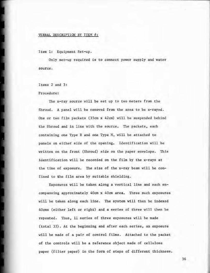
Item 1: Equipment Set-up.
Only set-up required is to connect power supply and water
source.
Items 2 and 3:
Procedure:
The x-ray source will be set up to two meters from the
Shroud. A panel will be removed from the area to be x-rayed.
One or two film packets (3Scm x 42cm) will be suspended behind
the Shroud and in line with the source. The packets, each
containing one Type R and one Type M, will be attached to
panels on either side of the opening. Identification will be
written on the front (Shroud) side on the paper envelope. This
identification will be recorded on the film by the x-rays at
the time of exposure. The size of the x-ray beam will be con
fined to .the film area by suitable shielding.
Exposures will be taken along a vertical line and each en
compassing approximately 40cm x 40cm area. Three such exposur.es
will be taken along each line . The system will then be indexed
40cms (either left or right) and a series of three will then be
repeated. Thus, 11 series of three exposures will be made
(total 33). At the beginning and after each series, an exposure
will be made of a pair of control films. Attached to the packet
of the controls will be a reference object made of cellulose
paper (filter paper) in the form of steps of different thickness.
36

Verbal Description by Item #
Page 2
Items 2 and 3 (cont.)
The exposed films will be developed, dried and their densities
measured prior to development of the Shroud films. This will be
to check the consistency of film development.
All films after development and drying and each having a
unique identification will be stored in paper envelopes appro
priately marked. Interpretation by qualified radiographers will
be performed in the U.S. Duplicate copies (1:1) will be made
as needed for use by the evaluators, the original retained as
archival films.
Safety Procedures:
To provide maximum safety to personnel, procedures will be
establi shed to confine the x-ray beam to the minimUII} size
necessary to expose film, to control the activities of a per
sonnel in the area, and to monitor the radiation levels in the
area.
Prior to the test, mapping of the radiation levels will be
performed and based on the results, barricades will be installed.
Prior to activating the x-ray equipment, one or more warning
beacons, will be turned on. Upon termination of an exposure,
the beacons will be turned off.
Personnel, other than team members, wishing to enter the
vicinity will be instructed in the safety procedures, sign a log
book ·and in some cases, provided a dosimeter. Readings from the
37

Verbal Description by Item #
Page 3
Items 2 and 3 (cont . )
dosimeter will be recorded upon entry and again on departure,
thus providing a record of exposures.
The Radiation Monitoring Technician will be responsib l e
for:
1 . Assisting in the radiation area moni t oring.
2 . Periodic survey of area.
3. Maintenance of log.
4. Issuance and retrieval of dosimeters.
5. Safety instruction of visitors (casuals) .
38

TEST PLAN FOR: X-RAY FLUORESCENCE
GROUP COORDINATOR: ROGER A. MORRIS
TEAM MEMBERS : J. RONALD LONDON
R. WILLIAM MOTTERN
.JOSEPH S. ACCETTA
BACKGROUND AND BASIC THEORY :
X-ray fluorescence anal ysis is capable of producing quan
titative estimates of the elemental content of an unknown
sample by exciting characteristic x- rays and measuring their
intensities. In the case of the Shroud, however, the experi
mental conditions preclude any attempt to make true quantita
tive judgements. Accordingly, the experimental plan will em
phasize the measurement of the experimental precision and the
production of qualitative results.
The priority list of areas to be inspected is (in order of
priority):
1 . Blood s t ain on the foot, dorsal image (see tape pl an) .
2. Control area near #1 (5 samples).
3. Vertical scan through image of fingers on right
hand (9, s-amples).
4. Control area near #3 (10 samples) .
5. Blood stain on face (3 mark).
6. Control area near US.
Prior to starting this series of data, the equipment will be
calibrated and the repeatability will be measured. A standard
object consisting of Cu, Mo and Ti will be counted 10 times by
39

Test plan for X-ray Fluorescence
Page 2
removing and replacing the object between counts. From this
data, the precision by which the object (Shroud) can be posi
tioned will be judged.
The purpose for including control areas in the priority
list should be obvious. Each control point will be counted a
minimum of three times at slightly different points ( <. l.Ocm
shift) to measure the variability of the object's elemental
content over a nominally uniform area.
The blood on the foot will be counted the same way as a
control point. This point ( #1 ) will be compared with the face
blood data (#5) to see if one of them (#5) has been retouched
by s ome unknown "artist".
Scan #3 is designed to collect data over a wide range of
image intensi ties. The results will be correlated with the
image intensity and significant correlation noted. The scan
will be parallel with the long dimension of the cloth which will
be (or should be) roughly parallel to the isotherms produced
in the 1532 fire.
All of the areas scanned (image as well as control points)
will also be covered by the UV scanner and the tape, the other
sampling tests. Radiography, IR and visible photography are all
100% samples and hence automatically cover the x-ray fluorescence.
If time permits, other points and lines will be scanned.
The exact areas will depend on the results obtained i n scans
40

Test plan for X-ray Fluorescence
Page 3
#1 through #6 as well as the results obtained by the other
experimentors.
41

OPERATION PLAN TIME TABLE FOR ___ x -_RA_ Y_ FL_u_o_R_E_sc_E_N_C_E ______ _
TOTAL HOURS
1 2 3 4 5 6 7 8 9 10 1 1 3 ITEM Ii
1
2
BLOCK f
3
4
5
FRONT 3
6
BLOCK 2
7
8
9
10
11
12
13
42
VERBAL DESCRIPTION BY ITEM #:
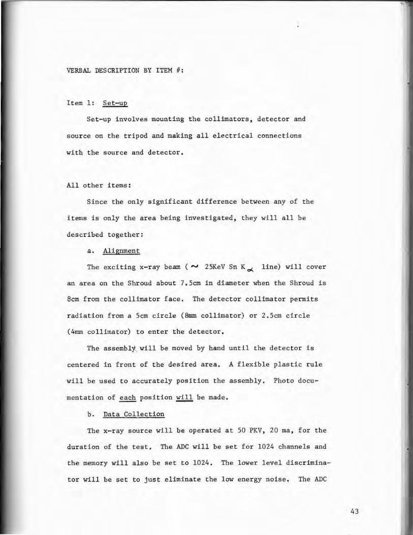
I tem 1: Set- up
Set-up involves mounting t he collimators, detector and
source on the tripod and making all electrical connections
with the source and de tector.
All other items:
Since the onl y significant difference between any of the
items is only the area being investigated , they will all be
described together:
a. Alignment
The exciting x-ray beam ( """' 25KeV Sn K cl... line) will cover
an area on the Shroud about 7. Scm in di ameter when the Shroud is
8cm from the collimator f ace. The det ector collimator permits
radiation from a Scro circle (8mm collimator) or 2.Scm circle
(4mm collimator) to enter the detector.
The assembly .. will be moved by hand until the detector is
centered in front of the desired ar ea . A flexibl e plastic rule
will be used to accurately position the assembly. Photo docu
mentation of each position !111, be made .
b. Data Collection
The x-ray sour ce will be opera ted at 50 PKV , 20 ma , for the
duration of the test, The ADC wi ll be set for 1024 channels and
the memory will a l so be set to 1024 , The lower level discri mina
tor will be set to just eliminate the low energy noise . The ADC
43

Verbal Descrip tion by I t em #:
Page 2
All other items : (cont . )
will operate in the PHA mode counting for a pre-set line time.
The time will be determined in Turin and will be sufficient
to insure precise results.
c . Data Storage
After the spectra i s collected, it will be visually
checked on the PHA CRT f or obvious errors , photographed , trans
mitted to a cassette , transmitted back to the FHA, visually
compared to the first photograph, and final l y transmitted again
to a differen t cassette . In this fashion , the correctness of
the data as stor ed on the fi r st cassette can be checked and a
duplicate tape made . The spectra photo will be used only for
the notebook.
A notebook will be maintained that lists :
1. The Shroud coordinates of every spectra stored .
2 . Starting tape coordinate of the spectra.
3,. Photo of s et- up.
4 . Photo of s pectra .
5 . Narrative description of location on Shroud,
6. Comments .
7 . Signatures .
Special Considerations
The irradiati on source is .a 50 PKV X- ray tube and emits
potentially dangerous x- rays. Accordingly , the number of people
44
Verbal Description by It~m # :
Page 3
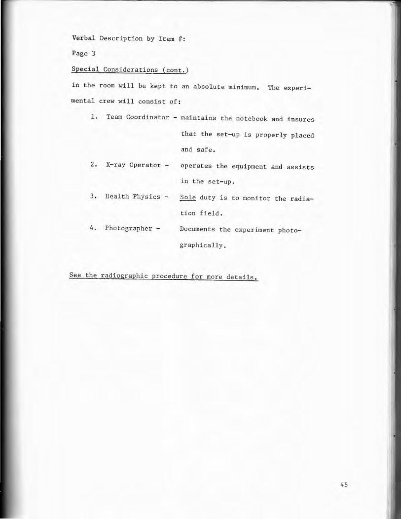
Special Considerations (cont.)
in the r oom will be kept to an absolute minimum. The experi
mental crew will consist of :
1 . Team Coordinator - maintains t he notebook and insures
that the set-up is properly placed
and safe .
2 . X- ray Operator -
3 . Heal th Physics -
4 . Photographer -
operates the equ ipment and ass i s ts
i n the set- up .
~ duty is to monitor the radia
tion field .
Documents the experiment photo
graphically .
See the r adiographic procedure for more details .
45

TEST PLAN FOR: INFRARED
GROUP COORDINATOR: JOSEPH S. ACCETTA
TEAM MEMBERS : TOM W. HAVERTY
J, STEPHEN BAUMGART
BACKGROUND AND BASIC THEORY:
Infrared investigations deal with a property of all matter
usually referred to a thermal radiation - that is , all objects
radiate energy over a wide range of wavelengths. The integrated
total energy over all wavelengths is usually expressed by the
modified Stefan- Boltzmann law fnr real bodies
E = ea T 4
where E is the emissive power in watts/cm2
a is the Stefan- Boltzmann constant
T is the absolute temperature in °K
e is the emissivity
'The quantity e expresses the emission efficiency of a radiat
ing body compared to a perfect emitter (a black body) .
The radiation properties are intimately connected with the
absorption quality of a surface. If an incident radiant inten
sity I shines on a surface, the energy is either reflected,
transmi tted or absorbed . This can be expressed mathematically
by the sum of the reflected fraction of the energy plus the
transmitted fraction plus the absorbed fraction being exactly
equal to the energy striking the surf ace or
p l + T I + a r -
where p is the reflectivity
T is the transmiss i vity
46

Test plan for Infrared
Page 2
a is the absorptivity
Thus, p + T .- a -= l
and this relationship also holds for a given wavelength, A,
Further , if the surface is opaque or nontransmitting, then T
i s zero and we have
P .... + a = l "' , A.
Further, for a given wavelength so that
In order, then, to determine either the reflectivity or emis-
sivity of an opaque surface we need only measure the one or t he
other .
Whi l e emission characteristics are not extremely dist i nct
f or given solid ~aterial , by looking at several aspects of the
surface characteristics in the infrared , some information might
be obtained .
This test is made up of several parts, each designed to
detect informat i on about the infrared radiation characteris-
tics of the Shroud sur f ace and possible changes due to the pre-
sence of the Shroud image . The first test is designed to simply
extend the photographic work into the near infrared region.
By selecting the lighting and selectively filtering the radia-
t ion returning to the camera, we intend to image t he Shroud in
47
Test plan for Infrared
Page 3
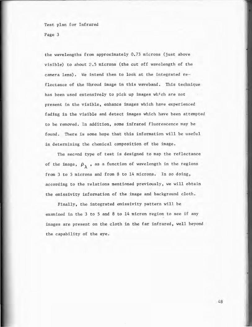
the wavel engths from approximately 0 . 73 microns (just above
visible) to abou t 2 . 5 microns ( the cut off wavelength of the
camera lens). We intend then to look at the integrated re
flectance of the Shroud image in this waveband. This technique
has been used extensively to pick up images wh~ch are not
present in the visible, enhance images which have experienced
fading in the visible and detect images which have been attempted
to be removed. In addition, some infrared fluorescence may be
found. There is some hope that this information will be useful
in determining the chemical composi~ion of the image.
The second type of test is designed to map the reflectance
of the image, p A , as a function of wavelength in the regions
from 3 to 5 microns and from 8 to 14 microns. In so doing,
according to the relations mentioned previously, we will obtain
the emissivity information of the image and background cloth.
Finally, the integrated emissivity pattern will be
examined in the 3 to 5 and 8 to 14 micron region to see if any
images are present on the cloth in the far infrared, well beyond
the capabi.lity of the eye.
48

OPERATION PLAN TIME TABLE FOR __ I_NF_RA_RE_D _____ __ _
2
3
4
s
6
7
8
9
TOTAL HOURS
1 2 3 4 5
ITEM ii
I i
Brrcr r I I I l I I I I I l I I I I I ! I I
' I I . I I I I ! I I I I I I I
~~~ ~----'--"---'----! 1__._I __.__j _..__ j B~OCf f l I I I I ! I i J . . . !
IT . I ~-1-L_l_+-L--L._1.-'l_l_-L--1.-L.......l-.--l..-L_L_J_J._--'--'- -' -l-.J"--L-~_J_J--1--'--'__._~~
. T Li I
I
.____.____.__.L.--1.-+--J~..l...___J______j__J_____L~____.___...___~_,__.___._ I I I l _ I I I I I I I I I
.__.___..__,_--+---'--- .~~I 1--L..-1--1 .1...--L...I 1---1-1 ....ll__.. l__._! I I I i I I l l I I I l J I I I I I
I I I I 10 h-,r 1 l- I I
ii-,-~~1--.--.--.---r-r--,--.-r~-.----r-.-r-r-r-T--r-,-,--,.---,-,-,----ll I I i I I I I I I i I I I I I I I I I
i i I i I I I l I I I I I I I I I I I I·
49

VERBAL DESCRIPTION BY ITEM #
Items 1 and 4:
Special procedure for infrared photography experiments in the
areas of Reflection, Transmiss l ·-: .. , Stimulated Emission (fluorescence),
and Film Processing.
REFLECTION ( This test to be run in conjuction with photographic tests)
a. Make final exposure and focus tes ts on actual target l n the 4x4 mode , the 30 cm x 30 cm mode , and the macro mode.
b. Energy source to be same strobes as used in photo tests except filtered.
c. Filters to be Wratten 89B (700nm), Wratten 87C (800nm), and Wratten 88A (7JOnm) (87C and 88A to be dropped at discression of test director) Wratten 12 to be used with color IR.
d. Camera to be suitable 35mm with 35mm and lOOnun macro lenses.
e. Film to be used Kodak Hi Speed Infrared HIE 135 - 20 and Kodak Infrared Ektachrome IE 135 - 20 .
f. Focus correction: focus thru Wratten 61 filter - value G focus t hru Wratten 29 filter - value R IR focus IR R+ 2(R-G) for apochromat lenses IR focus = IR = R+ 2.8(R-G) for achromatic lenses
g . Exposure base l ine : HIE fi lm and 89B filter use guide number of 100 HIE film and 88A filter use "guide number of 85 HIE film and 87C filter use guide number of 70 IE film and 12 filter use guide number of 200
h. Grid coverage to be same as in photo tests, see photo test plan for details.
4x4 grid 30x30 cm grid and macro
TRANSMISSION (this test to be r un at the end of the first photo test)
a. Using 4x4 grid system photograph using strobes (filtered) on the backside of the target with back pannels removed .
b . Exposure i ndex to be 1/10 th of reflection exposure for a baseline .
so

Verbal description by item # Page 2
Transmission c. (cont . )
c. HIE film and 89B , 87C, and 88A filters I E film and 12 filter
STIMULATED EMISSION
Blue green light: to be run with photo tests .
a . 4x4 grid mode in standard photo set up .
b . HIE film and 89B fil ter .
c.Two 500 watt spot lights with Corning glass 8780 and 3966 filters .
d . Focus correction as in IR 4x4 grid.
e . Exposure : six minutes at f/S.6.
f . During this test and all emission tests extreme care must be taken to exclude stray IR light from camera.
Ul tra violet: to be run with uv f luorescence tests.
a. 4x4 grid mode in standard photo set up .
b . HIE film and 89B filter .
c. uv lamps used in uv fluorscence tests.
d. Focus corr ection as in IR 4x4 grid.
e . Exposure: six minutes at f/5.6 .
f . During this test and all emission tests extreme care must be taken to exclude all stray IR light from camera .
X-ray emission : to be run with x-ray fluoescence test.
a . 4x4 grid mode in standard photo set up.
b. HIE film and 89B filter .
c . X-ray source used in x-ray emission test.
d . Focus correction as in IR 4x4 grid .
e. Exposure: six minutes at f/S . 6 .
51

Verbal description by item # Page 3
X-ray emission f. (cont.)
f. During this test and all emission tests extreme care must be taken to exclude all stray IR light from camera .
g . Camera should be shielded with lead foil to prevent x-ray fogging.
h . This test to be done at the discression of the x- ray safety officer and with his complete• control , with the understanding that the IR personel are not familar with x-ray dangers.
FILM PROCESSING
a . Preliminary test films will be processed immediately after exposure for evaluation necessary for focus and exposure data .
b . HIE film to be processed in for 11 minutes in D76 developer at 20°c . or 3 ft/min . in Versamat processer and Versaflo developer .
c . Darkroom to be checked by all owing an open roll of fil m (HIE). to r emain exposed for 30 minutes and then processed and examined for signs of fogging . Processer will also be checked by running an unexposed roll of HI E film thru at the slowest possible speed.
THIS TEST TO BE DONE PRIOR TO ANY FI LM HANDLING
d . IE film to be processed in process EAS or if not available E4 .
e . All IR film will be shipped in lead foil bags, and kept at 4°C . or colder.
52

TEST PLAN FOR: TAPE EXPERIMENT
GROUP COORDINATOR: RAYMOND N, ROGERS
TEAM MEMBERS: ROBERT H, DINEGAR
MARY A. STEVENSON
BACKGROUND AND BASIC THEORY:
Objective: To obtain minute samples of surface coloration
to be used for chemical analysis,
Method:
Analysis:
Apply chemically inert adhesive tape to
surface of cloth in carefully controlled
manner (with a pressure sensitive roller).
Withdraw with adhering surface sample.
Adhesive is pure hydrocarbon - inert, non
corrosive.
Since adhesive is hydrocarbon, it will not
produce confusing background during chemical
analyses; therefore,
(a) surf aces can be analyzed by electron
spin resonance (observing free radicals);
(b) by electron spectroscopy (observing
chemical bond types);
(c) by scanning electron microscopy
(observing color-body structure and
elemental composition); and
(d) by ion microprobe (observing chemical
composition) ,
53

OPERATION PLAN TIME TABLE FOR TAPE SAMPLE ANALYSIS
TOTAL HOURS
1 2 3 4 5
ITEM 1f
I I I I l I I I I l I I I I I I l I 2 s
3 1--'---'---''"-----'------.--'--_D_ I I I I I I I I I I I I U l I I I I LI I I I I I l_J
5
7
8
9
11
12
13
!I .I
I I I
54

TEST PLAN FOR: ULTRAVIOLET - VI SIBLE SPECTROSCOPY
GROUP COORDINATOR : ROGER GILBERT , JR.
TEAM MEMBER : MARTY GILBERT
BACKGROUND AND BASIC THEORY :
The objectives of t hes e tes t s are to obtain ultraviolet
visible reflectance spectr a and u ltraviolet fluorescence spect ra
to aid the analysis of substances found on various parts of t he
Shroud , especially t he body i mage , blood and serum stains and
water marks . The ref l ectance spectra will also support the spec
tral photographic work .
DESCRIPTION OF TESTS ON THE SHROUD:
At each of thirty spot s on the Shroud, we will obtain a plot
of refl 0 ctance vs. wavel engt h in the ultraviolet and visibl e spec
tral regions from 250 t o 750 nanometers . We will also measure
fluorescence vs . wavelength using both 365 run and 248 run ultra
violet excitation. For the reflectance measurements , white
light from a xenon lamp i llumi nates the entrance slit of a mono
chromator whi ch divides t he beam into its spectrum and produces
monochromatic light (light of a single color or wavelength) at
the exit slit . The monochromatic exit beam i s focused onto a
small 3 by 5mm spo t on the Shr oud , The l ight , reflected from the
Shroud, travel s through a second monochromator and then to a pho t o
multiplier detector .
The monochromators are then scanned i n unison through the
spectrum f rom 250 nm i n t he ultravioV~t thro11gh the visible region
55
Tes t pl~n for ULTRAVIOLET - VISIBLE SPECTROSCOPY
Page 2
f rom 400 to 700 nm to the 750 nm i n the near infr ared . The wave
length is e l ectronically displayed on t he horizontal (or X) axis
of an X-Y recorder. The ref lected light level measured by the
photomultiplier i s fed to the vertical (or Y) axis . As the mono
chromators are scanned, a plot of relative reflec t ance vs . wave
length is obta~ned.
Wldle doing fluorescence measurements , a mercury lamp is used.
The monochromator on the light source side :i.s fixed at ei ther 365 nm
or 248 nm in the ultraviolet. This "excitation" ultraviolet energy
is absorbed by the clot h causing the cloth to "fluoresce" or to
emit longer wavelength visibl e l i ght . The monochromator on the
detector s i de will be scanned to obtain a spectral plot of this
fluorescence .
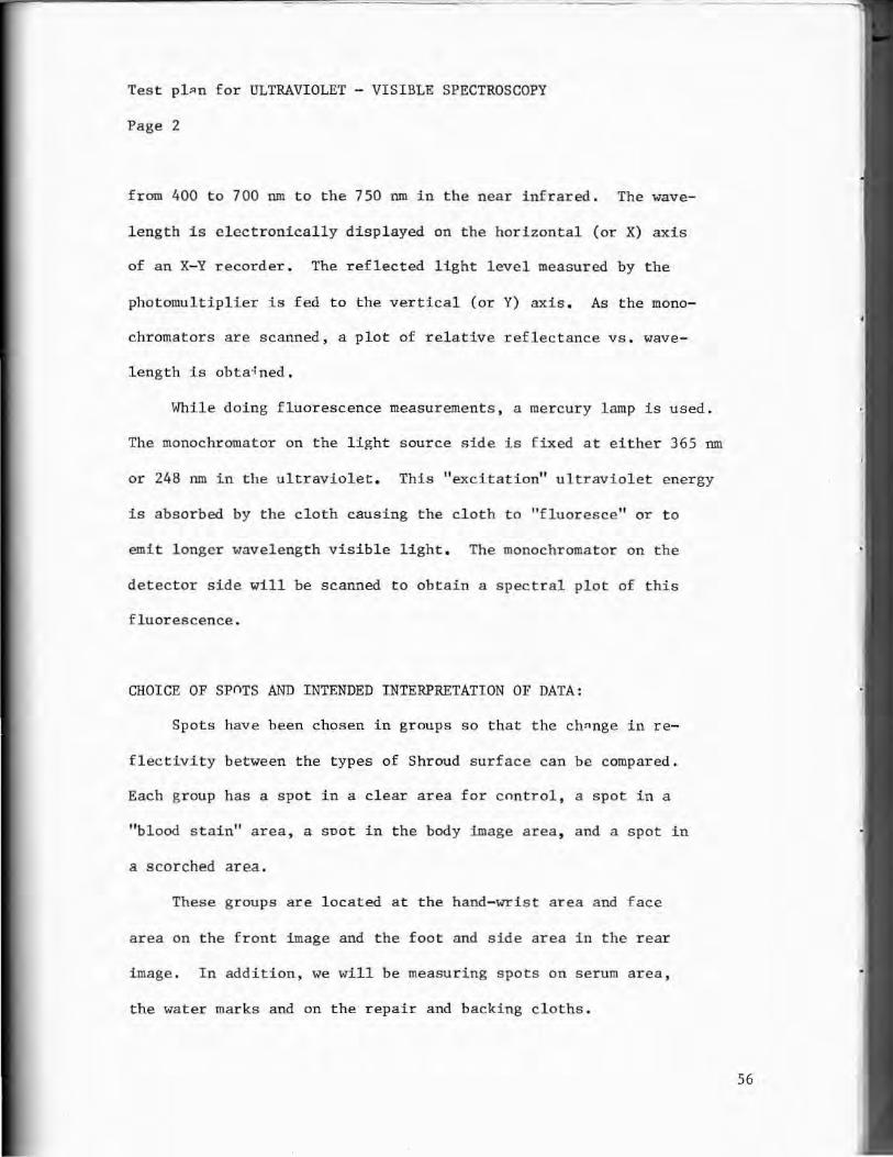
CHOICE OF spnrs AND INTENDED INTERPRETATI ON OF DATA :
Spots have been chosen in groups so tha t the ch~nge in re
flectivity between the types of Shroud surface can be compared.
Each group has a spot in a clear area for control , a spot in a
"blood stai n" area , a soot in the body image area, and a spot in
a scor ched area .
These gr oups are l ocated at the hand-wrist area and face
area on the front i mage and the foot and side area in the rear
image . In additi on, we will be measuring spots on serum area ,
the water marks and on the repair and backing cloths .
56

Test plan for ULTRAVIOLET - VISIBLE SPECTROSCOPY
Page 3
By comparing the reflectivities of the image stain, blood
s t ain and scorched areas with that of the clear area, we can
produce approximate plots of absorption of the stains themselves.
These can be compared with similar spectral data on known com
pounds and on known pigments and coloring agents. The reflecti
vity of image and blood stains can also be compared with that of
the scorched areas ,
The spectral plots of the clear areas as well as the back
ing and repair cloths will be compared to a magnesium oxide re
ference for possible future comparison with other known cloths .
. The fluorescence spectra will be corrected for spectral vari~
ances within the measuring instrument and replotted, These
corrected spectral plots can then be compared with those of
known compounds pigments and coloring agents . Again, we can
compare the image and blood stain f luorescence with that of the
scnrched area.
SAFETY CONSIDERATIONS :
In this measurement , the maximum power incident on the
Shroud on the 3 x 5mm spot is less than 1 milliwatt (one thou
sandth of a watt). This corresponds to approximately 7% of the
total irradiance from the sun. This should prnduce a temperature
rise on the cloth of less than .1°C.
The possibility of ultraviolet degradation has been investi
gated by subjecting a test linen cloth with a dyed area and a
57

Test plan for ULTRAVIOLET - VISIBLE SPECTROSCOPY
Page 4
scorched area and a clear area to an accelerated test . Exposur es
at 248 and 365 nm of fif t y times the maximum that will be used
during these tests produced no discernable damage to the test
cloth.
58
OPERATION PLAN TIME TABLE FOR ULTRAVIOLET - VISIBLE SPECTROSCOPY ---~~~~~~~~~~~~~~~~
TOTAL HOURS
1 2 3 4 5 6 7 8 9 10 1 1 3 ITEM if
1
2
3
FRONT 8
4 I I I I I 1- I I I I I BACK 2
s
6
7
8
9
10 I I
11
12
PERMITS)
13
14
59

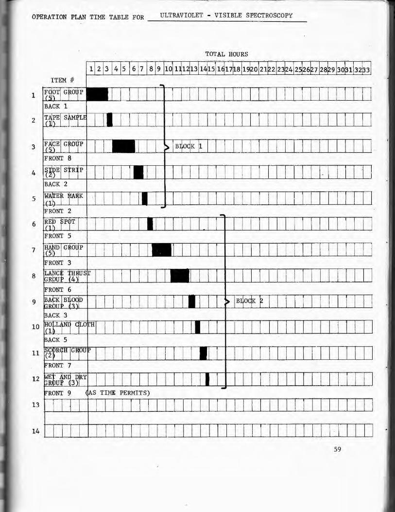
VERBAL DESCRIPTION BY ITEM ti
ALL ITEMS:
. Spectral scans of reflectivity from 250 - 750 nm and of
fluorescence using both 365 and 248 run excitation wil l be made
on 30 points on the Shroud (15 points on the one day plan).
Present plans call for performing the reflectivity scans on
groups of 5 - 7 spots then converting the instrument to the
fluorescence mode and doing fluorescence scans on the same group .
This will necessitate two setups for each spot. We are now in
vestigating a fast convers~on which will allow us to do ref lecti
vi ty and fluorescence on the same spot without moving the
instrument . Each reflectivity scan includi ng setup should take
approximate l y 10 minutes. Each fluorescence scan series (i.e.
both at 248 and 365 mn) will take approximately 12 minutes. All
30 spots will take 660 minutes or 11 hours. 15 spots will take
5.5 hours. A copy of the list of spots by Shroud location and
the operation plan time table showing spots in initial order of
priority is attached .
ELECTRICAL REQUIREMENTS:
If possible, we would like 110 volts - 60 Hz at 12 amperes
f r om one power converter and an additional 6 amperes from another.
We may have two lamp power supplies going at the same time. Being
SCR regulated , they do feed some spikes back into t he line which
may interfere with other equipment on at the same time.
60

Verbal" Description by Item#
Page 2
All Items (cont.)
Perhaps if we had one power converter for our use only during
our test period, the other group operating with us could use the
other converter.
In a pinch, we could operate direct ly from the 220V 50 Hz
line, but with more risk, (Only one of our two recorders operates
at 50 Hz).
PHOTOGRAPHIC REQUIREMENTS:
We would like documenta tion photographs of each setup
showing the illuminated spot on the Shroud ,
We will have either 30 or 60 setups depending on whether we
can quick convert between reflectance and fluorescence or not .
This will be cu t to 15 or 30 setups on a one day plan.
61