Embed Size (px)
Citation preview

8/16/2019 Student Manual _ ABT-CCP-TSM143 _ RSLogix 5000, Level 3 _ Project Development.pdf
http://slidepdf.com/reader/full/student-manual-abt-ccp-tsm143-rslogix-5000-level-3-project-developmentpdf 1/375
Student Manual
RSLogix™ 5000Level 3: ProjectDevelopment

8/16/2019 Student Manual _ ABT-CCP-TSM143 _ RSLogix 5000, Level 3 _ Project Development.pdf
http://slidepdf.com/reader/full/student-manual-abt-ccp-tsm143-rslogix-5000-level-3-project-developmentpdf 2/375
Important User Information
This documentation, whether, illustrative, printed, “online” or electronic (hereinafter “Documentation”) is intended for
use only as a learning aid when using Rockwell Automation approved demonstration hardware, software and firmware.
The Documentation should only be used as a learning tool by qualified professionals.
The variety of uses for the hardware, software and firmware (hereinafter “Products”) described in this Documentation,
mandates that those responsible for the application and use of those Products must satisfy themselves that all necessary
steps have been taken to ensure that each application and actual use meets all performance and safety requirements,
including any applicable laws, regulations, codes and standards in addition to any applicable technical documents.
In no event will Rockwell Automation, Inc., or any of its affiliate or subsidiary companies (hereinafter “Rockwell
Automation”) be responsible or liable for any indirect or consequential damages resulting from the use or application of
the Products described in this Documentation. Rockwell Automation does not assume responsibility or liability for
damages of any kind based on the alleged use of, or reliance on, this Documentation.
No patent liability is assumed by Rockwell Automation with respect to use of information, circuits, equipment, or
software described in the Documentation.
Except as specifically agreed in writing as part of a maintenance or support contract, equipment users are responsible for:
properly using, calibrating, operating, monitoring and maintaining all Products consistent with all Rockwell
Automation or third--party provided instructions, warnings, recommendations and documentation;
ensuring that only properly trained personnel use, operate and maintain the Products at all times;
staying informed of all Product updates and alerts and implementing all updates and fixes; and
all other factors affecting the Products that are outside of the direct control of Rockwell Automation.
Reproduction of the contents of the Documentation, in whole or in part, without written permission of Rockwell
Automation is prohibited.
Throughout this manual we use the following notes to make you aware of safety considerations:
Identifies information about practices or circumstancesthat can cause an explosion in a hazardous environment,
which may lead to personal injury or death, property
damage, or economic loss.
Identifies information that is critical for successful
application and understanding of the product.
Identifies information about practices or circumstances
that can lead to personal injury or death, propertydamage, or economic loss. Attentions help you:
identify a hazardavoid a hazardrecognize the consequence

8/16/2019 Student Manual _ ABT-CCP-TSM143 _ RSLogix 5000, Level 3 _ Project Development.pdf
http://slidepdf.com/reader/full/student-manual-abt-ccp-tsm143-rslogix-5000-level-3-project-developmentpdf 3/375
Important User Information
Labels may be located on or inside the drive to alert
people that dangerous voltage may be present.
Labels may be located on or inside the drive to alert
people that surfaces may be dangerous temperatures.

8/16/2019 Student Manual _ ABT-CCP-TSM143 _ RSLogix 5000, Level 3 _ Project Development.pdf
http://slidepdf.com/reader/full/student-manual-abt-ccp-tsm143-rslogix-5000-level-3-project-developmentpdf 4/375

8/16/2019 Student Manual _ ABT-CCP-TSM143 _ RSLogix 5000, Level 3 _ Project Development.pdf
http://slidepdf.com/reader/full/student-manual-abt-ccp-tsm143-rslogix-5000-level-3-project-developmentpdf 5/375

8/16/2019 Student Manual _ ABT-CCP-TSM143 _ RSLogix 5000, Level 3 _ Project Development.pdf
http://slidepdf.com/reader/full/student-manual-abt-ccp-tsm143-rslogix-5000-level-3-project-developmentpdf 6/375

8/16/2019 Student Manual _ ABT-CCP-TSM143 _ RSLogix 5000, Level 3 _ Project Development.pdf
http://slidepdf.com/reader/full/student-manual-abt-ccp-tsm143-rslogix-5000-level-3-project-developmentpdf 7/375
Comment Form
Email: [email protected]
or Fax: 440.646.4425
Page 1 of
Date:
Contact Information:
Name:
Company and Location:
Phone: Email:
Comments (include lesson title, if applicable):
Course or Product Name (Important):

8/16/2019 Student Manual _ ABT-CCP-TSM143 _ RSLogix 5000, Level 3 _ Project Development.pdf
http://slidepdf.com/reader/full/student-manual-abt-ccp-tsm143-rslogix-5000-level-3-project-developmentpdf 8/375

8/16/2019 Student Manual _ ABT-CCP-TSM143 _ RSLogix 5000, Level 3 _ Project Development.pdf
http://slidepdf.com/reader/full/student-manual-abt-ccp-tsm143-rslogix-5000-level-3-project-developmentpdf 9/375
Page 2

8/16/2019 Student Manual _ ABT-CCP-TSM143 _ RSLogix 5000, Level 3 _ Project Development.pdf
http://slidepdf.com/reader/full/student-manual-abt-ccp-tsm143-rslogix-5000-level-3-project-developmentpdf 10/375

8/16/2019 Student Manual _ ABT-CCP-TSM143 _ RSLogix 5000, Level 3 _ Project Development.pdf
http://slidepdf.com/reader/full/student-manual-abt-ccp-tsm143-rslogix-5000-level-3-project-developmentpdf 11/375
Introduction
Course Overview I. . . . . . . . . . . . . . . . . . . . . . . . . . . . . . . . . . . . . . . . . . . . . . . . . . .Course Purpose I. . . . . . . . . . . . . . . . . . . . . . . . . . . . . . . . . . . . . . . . . . . . . . . . . . . . . . . . . . . . .
Who Should Attend I. . . . . . . . . . . . . . . . . . . . . . . . . . . . . . . . . . . . . . . . . . . . . . . . . . . . . . . . . .
Prerequisites II. . . . . . . . . . . . . . . . . . . . . . . . . . . . . . . . . . . . . . . . . . . . . . . . . . . . . . . . . . . . . . .
Agenda II. . . . . . . . . . . . . . . . . . . . . . . . . . . . . . . . . . . . . . . . . . . . . . . . . . . . . . . . . . . . . . . . . . .
Meeting Course Objectives III. . . . . . . . . . . . . . . . . . . . . . . . . . . . . . . . . . . . . . . . . . . . . . . . . . . . .
Student Materials IV. . . . . . . . . . . . . . . . . . . . . . . . . . . . . . . . . . . . . . . . . . . . . . . . . . . . . . . . . . . .
Hands-On Exercises IV. . . . . . . . . . . . . . . . . . . . . . . . . . . . . . . . . . . . . . . . . . . . . . . . . . . . . . . . .
Certificate Candidates IV. . . . . . . . . . . . . . . . . . . . . . . . . . . . . . . . . . . . . . . . . . . . . . . . . . . . . . . .
Configuration and Programming Examples V. . . . . . . . . . . . . . . . . . . . . . . . . . . . . . . . . . . . . . . . . .
ControlLogix/RSLogix 5000 Curriculum Map V. . . . . . . . . . . . . . . . . . . . . . . . . . . . . . . . . . . . . . . . .
Lessons
Updating Logix5000 Firmware 1- 1. . . . . . . . . . . . . . . . . . . . . . . . . . . . . . . . . . . . . . . . .What You Will Learn 1--1. . . . . . . . . . . . . . . . . . . . . . . . . . . . . . . . . . . . . . . . . . . . . . . . . . . . . . . . . .
When You Will Do This 1--1. . . . . . . . . . . . . . . . . . . . . . . . . . . . . . . . . . . . . . . . . . . . . . . . . . . . . .
Before You Begin 1--1. . . . . . . . . . . . . . . . . . . . . . . . . . . . . . . . . . . . . . . . . . . . . . . . . . . . . . . . . . . .
Review 1--1. . . . . . . . . . . . . . . . . . . . . . . . . . . . . . . . . . . . . . . . . . . . . . . . . . . . . . . . . . . . . . . . .
Updating Module Firmware 1--1. . . . . . . . . . . . . . . . . . . . . . . . . . . . . . . . . . . . . . . . . . . . . . . . . . .
Here’s How 1--3. . . . . . . . . . . . . . . . . . . . . . . . . . . . . . . . . . . . . . . . . . . . . . . . . . . . . . . . . . . . . . . .
Demonstration Checklist 1--3. . . . . . . . . . . . . . . . . . . . . . . . . . . . . . . . . . . . . . . . . . . . . . . . . . . . . . .
Exercise: Updating Logix5000 Firmware 1- 5. . . . . . . . . . . . . . . . . . . . . . . . . . . . . . . . .Exercise A 1--5. . . . . . . . . . . . . . . . . . . . . . . . . . . . . . . . . . . . . . . . . . . . . . . . . . . . . . . . . . . . . . . . .
How Did You Do? 1--6. . . . . . . . . . . . . . . . . . . . . . . . . . . . . . . . . . . . . . . . . . . . . . . . . . . . . . . . . . . .
Answers 1--8. . . . . . . . . . . . . . . . . . . . . . . . . . . . . . . . . . . . . . . . . . . . . . . . . . . . . . . . . . . . . . . . . .
Exercise A 1--8. . . . . . . . . . . . . . . . . . . . . . . . . . . . . . . . . . . . . . . . . . . . . . . . . . . . . . . . . . . . . . .
Creating and Organizing a New RSLogix 5000 Project 2- 1. . . . . . . . . . . . . . . . . . . . . . .What You Will Learn 2--1. . . . . . . . . . . . . . . . . . . . . . . . . . . . . . . . . . . . . . . . . . . . . . . . . . . . . . . . . .
When You Will Do This 2--1. . . . . . . . . . . . . . . . . . . . . . . . . . . . . . . . . . . . . . . . . . . . . . . . . . . . . .
Before You Begin 2--1. . . . . . . . . . . . . . . . . . . . . . . . . . . . . . . . . . . . . . . . . . . . . . . . . . . . . . . . . . . .
Key Terms 2--1. . . . . . . . . . . . . . . . . . . . . . . . . . . . . . . . . . . . . . . . . . . . . . . . . . . . . . . . . . . . . . .
Project Organization 2--1. . . . . . . . . . . . . . . . . . . . . . . . . . . . . . . . . . . . . . . . . . . . . . . . . . . . . . . .
Default Project Structure 2--2. . . . . . . . . . . . . . . . . . . . . . . . . . . . . . . . . . . . . . . . . . . . . . . . . . .
Creating a New Task 2--2. . . . . . . . . . . . . . . . . . . . . . . . . . . . . . . . . . . . . . . . . . . . . . . . . . . . . . .
Continuous Task 2--3. . . . . . . . . . . . . . . . . . . . . . . . . . . . . . . . . . . . . . . . . . . . . . . . . . . . . . . .
Watchdog Timers 2--3. . . . . . . . . . . . . . . . . . . . . . . . . . . . . . . . . . . . . . . . . . . . . . . . . . . . . . . . . .
Table of Contents

8/16/2019 Student Manual _ ABT-CCP-TSM143 _ RSLogix 5000, Level 3 _ Project Development.pdf
http://slidepdf.com/reader/full/student-manual-abt-ccp-tsm143-rslogix-5000-level-3-project-developmentpdf 12/375
Table of Contentsii
Inhibited Task 2--4. . . . . . . . . . . . . . . . . . . . . . . . . . . . . . . . . . . . . . . . . . . . . . . . . . . . . . . . . . .
Creating a Program 2--4. . . . . . . . . . . . . . . . . . . . . . . . . . . . . . . . . . . . . . . . . . . . . . . . . . . . . . . .
Adjusting a Program Schedule 2--5. . . . . . . . . . . . . . . . . . . . . . . . . . . . . . . . . . . . . . . . . . . . . . .
Actual Program Scan Time 2--5. . . . . . . . . . . . . . . . . . . . . . . . . . . . . . . . . . . . . . . . . . . . . . . . .
Creating a Routine 2--6. . . . . . . . . . . . . . . . . . . . . . . . . . . . . . . . . . . . . . . . . . . . . . . . . . . . . . . . .
Program Control Instructions 2--8. . . . . . . . . . . . . . . . . . . . . . . . . . . . . . . . . . . . . . . . . . . . . . . .System Overhead Timeslice 2--8. . . . . . . . . . . . . . . . . . . . . . . . . . . . . . . . . . . . . . . . . . . . . . . . . .
Asynchronous Updates 2--9. . . . . . . . . . . . . . . . . . . . . . . . . . . . . . . . . . . . . . . . . . . . . . . . . . . . . .
Project Organization Best Practices 2--10. . . . . . . . . . . . . . . . . . . . . . . . . . . . . . . . . . . . . . . . . . . . .
Example: Project Organization 2--11. . . . . . . . . . . . . . . . . . . . . . . . . . . . . . . . . . . . . . . . . . . . . . .
Verifying Tasks, Programs, and Routines 2--11. . . . . . . . . . . . . . . . . . . . . . . . . . . . . . . . . . . . . . . . .
Here’s How 2--12. . . . . . . . . . . . . . . . . . . . . . . . . . . . . . . . . . . . . . . . . . . . . . . . . . . . . . . . . . . . . . . .
Example 2--12. . . . . . . . . . . . . . . . . . . . . . . . . . . . . . . . . . . . . . . . . . . . . . . . . . . . . . . . . . . . . . . . . .
Here’s How 2--13. . . . . . . . . . . . . . . . . . . . . . . . . . . . . . . . . . . . . . . . . . . . . . . . . . . . . . . . . . . . . . . .
Demonstration Checklist 2--13. . . . . . . . . . . . . . . . . . . . . . . . . . . . . . . . . . . . . . . . . . . . . . . . . . . . . . .
Exercise: Creating and Organizing a New RSLogix 5000 Project 2-15. . . . . . . . . . . . . . .Exercise A 2--15. . . . . . . . . . . . . . . . . . . . . . . . . . . . . . . . . . . . . . . . . . . . . . . . . . . . . . . . . . . . . . . . .
How Did You Do? 2--17. . . . . . . . . . . . . . . . . . . . . . . . . . . . . . . . . . . . . . . . . . . . . . . . . . . . . . . . . . . .
Answers 2--18. . . . . . . . . . . . . . . . . . . . . . . . . . . . . . . . . . . . . . . . . . . . . . . . . . . . . . . . . . . . . . . . . .
Exercise A 2--18. . . . . . . . . . . . . . . . . . . . . . . . . . . . . . . . . . . . . . . . . . . . . . . . . . . . . . . . . . . . . . .
Creating a Periodic Task in an RSLogix 5000 Project 3- 1. . . . . . . . . . . . . . . . . . . . . . . .What You Will Learn 3--1. . . . . . . . . . . . . . . . . . . . . . . . . . . . . . . . . . . . . . . . . . . . . . . . . . . . . . . . . .
When You Will Do This 3--1. . . . . . . . . . . . . . . . . . . . . . . . . . . . . . . . . . . . . . . . . . . . . . . . . . . . . .
Before You Begin 3--1. . . . . . . . . . . . . . . . . . . . . . . . . . . . . . . . . . . . . . . . . . . . . . . . . . . . . . . . . . . .
Task Type Review 3--1. . . . . . . . . . . . . . . . . . . . . . . . . . . . . . . . . . . . . . . . . . . . . . . . . . . . . . . . .
Periodic Task 3--2. . . . . . . . . . . . . . . . . . . . . . . . . . . . . . . . . . . . . . . . . . . . . . . . . . . . . . . . . . . . .
Example: Periodic Task Use 3--2. . . . . . . . . . . . . . . . . . . . . . . . . . . . . . . . . . . . . . . . . . . . . . . .
Example: Project Organization 3--3. . . . . . . . . . . . . . . . . . . . . . . . . . . . . . . . . . . . . . . . . . . . . . .
Periodic Task Properties 3--4. . . . . . . . . . . . . . . . . . . . . . . . . . . . . . . . . . . . . . . . . . . . . . . . . . . . .
Period 3--4. . . . . . . . . . . . . . . . . . . . . . . . . . . . . . . . . . . . . . . . . . . . . . . . . . . . . . . . . . . . . . . .
Priority 3--5. . . . . . . . . . . . . . . . . . . . . . . . . . . . . . . . . . . . . . . . . . . . . . . . . . . . . . . . . . . . . . .
Scan Time Values 3--6. . . . . . . . . . . . . . . . . . . . . . . . . . . . . . . . . . . . . . . . . . . . . . . . . . . . . . . .
Periodic Task Execution 3--6. . . . . . . . . . . . . . . . . . . . . . . . . . . . . . . . . . . . . . . . . . . . . . . . . . . . .
Example: Periodic Task 3--6. . . . . . . . . . . . . . . . . . . . . . . . . . . . . . . . . . . . . . . . . . . . . . . . . . . .
Example: Periodic Task and Continuous Task 3--7. . . . . . . . . . . . . . . . . . . . . . . . . . . . . . . . . . . .Example: Multiple Tasks 3--7. . . . . . . . . . . . . . . . . . . . . . . . . . . . . . . . . . . . . . . . . . . . . . . . . . .
Example: Equal Priorities (Timeslicing) 3--7. . . . . . . . . . . . . . . . . . . . . . . . . . . . . . . . . . . . . . . . .
Here’s How 3--8. . . . . . . . . . . . . . . . . . . . . . . . . . . . . . . . . . . . . . . . . . . . . . . . . . . . . . . . . . . . . . . .
Example 3--8. . . . . . . . . . . . . . . . . . . . . . . . . . . . . . . . . . . . . . . . . . . . . . . . . . . . . . . . . . . . . . . . . .
Here’s How 3--9. . . . . . . . . . . . . . . . . . . . . . . . . . . . . . . . . . . . . . . . . . . . . . . . . . . . . . . . . . . . . . . .
Demonstration Checklist 3--9. . . . . . . . . . . . . . . . . . . . . . . . . . . . . . . . . . . . . . . . . . . . . . . . . . . . . . .

8/16/2019 Student Manual _ ABT-CCP-TSM143 _ RSLogix 5000, Level 3 _ Project Development.pdf
http://slidepdf.com/reader/full/student-manual-abt-ccp-tsm143-rslogix-5000-level-3-project-developmentpdf 13/375
Table of Contents iii
Exercise: Creating a Periodic Task in an RSLogix 5000 Project 3-11. . . . . . . . . . . . . . . .Exercise A 3--11. . . . . . . . . . . . . . . . . . . . . . . . . . . . . . . . . . . . . . . . . . . . . . . . . . . . . . . . . . . . . . . . .
How Did You Do? 3--12. . . . . . . . . . . . . . . . . . . . . . . . . . . . . . . . . . . . . . . . . . . . . . . . . . . . . . . . . . . .
Answers 3--14. . . . . . . . . . . . . . . . . . . . . . . . . . . . . . . . . . . . . . . . . . . . . . . . . . . . . . . . . . . . . . . . . .
Exercise A 3--14. . . . . . . . . . . . . . . . . . . . . . . . . . . . . . . . . . . . . . . . . . . . . . . . . . . . . . . . . . . . . . .
Organizing Data in an RSLogix 5000 Project 4- 1. . . . . . . . . . . . . . . . . . . . . . . . . . . . . .What You Will Learn 4--1. . . . . . . . . . . . . . . . . . . . . . . . . . . . . . . . . . . . . . . . . . . . . . . . . . . . . . . . . .
When You Will Do This 4--1. . . . . . . . . . . . . . . . . . . . . . . . . . . . . . . . . . . . . . . . . . . . . . . . . . . . . .
Before You Begin 4--1. . . . . . . . . . . . . . . . . . . . . . . . . . . . . . . . . . . . . . . . . . . . . . . . . . . . . . . . . . . .
Controller Memory 4--1. . . . . . . . . . . . . . . . . . . . . . . . . . . . . . . . . . . . . . . . . . . . . . . . . . . . . . . . .
Data Types 4--2. . . . . . . . . . . . . . . . . . . . . . . . . . . . . . . . . . . . . . . . . . . . . . . . . . . . . . . . . . . . . .
Memory Allocation 4--3. . . . . . . . . . . . . . . . . . . . . . . . . . . . . . . . . . . . . . . . . . . . . . . . . . . . . . . . .
Tag Scope 4--4. . . . . . . . . . . . . . . . . . . . . . . . . . . . . . . . . . . . . . . . . . . . . . . . . . . . . . . . . . . . . . .
Creating a Tag 4--4. . . . . . . . . . . . . . . . . . . . . . . . . . . . . . . . . . . . . . . . . . . . . . . . . . . . . . . . . . . .
Tag Name 4--5. . . . . . . . . . . . . . . . . . . . . . . . . . . . . . . . . . . . . . . . . . . . . . . . . . . . . . . . . . . . .Data Type 4--5. . . . . . . . . . . . . . . . . . . . . . . . . . . . . . . . . . . . . . . . . . . . . . . . . . . . . . . . . . . . .
Style 4--5. . . . . . . . . . . . . . . . . . . . . . . . . . . . . . . . . . . . . . . . . . . . . . . . . . . . . . . . . . . . . . . . .
Defining an Alias Tag 4--6. . . . . . . . . . . . . . . . . . . . . . . . . . . . . . . . . . . . . . . . . . . . . . . . . . . . . . .
Produced and Consumed Tags 4--6. . . . . . . . . . . . . . . . . . . . . . . . . . . . . . . . . . . . . . . . . . . . . .
Creating an Array of Tags 4--7. . . . . . . . . . . . . . . . . . . . . . . . . . . . . . . . . . . . . . . . . . . . . . . . . . . .
Example: Array 4--7. . . . . . . . . . . . . . . . . . . . . . . . . . . . . . . . . . . . . . . . . . . . . . . . . . . . . . . . .
Array Storage 4--8. . . . . . . . . . . . . . . . . . . . . . . . . . . . . . . . . . . . . . . . . . . . . . . . . . . . . . . . . . . .
Example: Three Dimensional Array 4--8. . . . . . . . . . . . . . . . . . . . . . . . . . . . . . . . . . . . . . . . . . .
Array Addressing 4--9. . . . . . . . . . . . . . . . . . . . . . . . . . . . . . . . . . . . . . . . . . . . . . . . . . . . . . . . . .
Numeric Element Addressing 4--9. . . . . . . . . . . . . . . . . . . . . . . . . . . . . . . . . . . . . . . . . . . . . . .
Example: Numeric Element Addressing 4--9. . . . . . . . . . . . . . . . . . . . . . . . . . . . . . . . . . . . . . . .
Example: Numeric Element Addressing for Multiple Dimensions 4--9. . . . . . . . . . . . . . . . . . . . . . .
Variable Element Addressing 4--10. . . . . . . . . . . . . . . . . . . . . . . . . . . . . . . . . . . . . . . . . . . . . . . .
Example: Variable Element Addressing 4--10. . . . . . . . . . . . . . . . . . . . . . . . . . . . . . . . . . . . . . . .
Numeric Bit Addressing 4--10. . . . . . . . . . . . . . . . . . . . . . . . . . . . . . . . . . . . . . . . . . . . . . . . . . . .
Example: Numeric Bit Addressing 4--10. . . . . . . . . . . . . . . . . . . . . . . . . . . . . . . . . . . . . . . . . . . .
Variable Bit Addressing 4--11. . . . . . . . . . . . . . . . . . . . . . . . . . . . . . . . . . . . . . . . . . . . . . . . . . . .
Example: Variable Bit Addressing 4--11. . . . . . . . . . . . . . . . . . . . . . . . . . . . . . . . . . . . . . . . . . . . .
Array Addressing Summary 4--11. . . . . . . . . . . . . . . . . . . . . . . . . . . . . . . . . . . . . . . . . . . . . . . . .
Verifying Tags 4--11. . . . . . . . . . . . . . . . . . . . . . . . . . . . . . . . . . . . . . . . . . . . . . . . . . . . . . . . . . . .
Monitoring and Editing Data 4--11. . . . . . . . . . . . . . . . . . . . . . . . . . . . . . . . . . . . . . . . . . . . . . . . . .Monitor Tags Tab 4--12. . . . . . . . . . . . . . . . . . . . . . . . . . . . . . . . . . . . . . . . . . . . . . . . . . . . . . . .
Tags and Members 4--12. . . . . . . . . . . . . . . . . . . . . . . . . . . . . . . . . . . . . . . . . . . . . . . . . . . . . . .
Display Style 4--12. . . . . . . . . . . . . . . . . . . . . . . . . . . . . . . . . . . . . . . . . . . . . . . . . . . . . . . . . . .
Example: 4--12. . . . . . . . . . . . . . . . . . . . . . . . . . . . . . . . . . . . . . . . . . . . . . . . . . . . . . . . . . . . . .
Monitoring and Editing Tag Values through a Routine 4--13. . . . . . . . . . . . . . . . . . . . . . . . . . . . . . . . .
Example: Ladder Logic Routine 4--13. . . . . . . . . . . . . . . . . . . . . . . . . . . . . . . . . . . . . . . . . . . . . .
Example: Function Block Diagram Routine 4--14. . . . . . . . . . . . . . . . . . . . . . . . . . . . . . . . . . . . . .
Monitoring and Editing Tag Values in the Watch Tab 4--15. . . . . . . . . . . . . . . . . . . . . . . . . . . . . . . . .

8/16/2019 Student Manual _ ABT-CCP-TSM143 _ RSLogix 5000, Level 3 _ Project Development.pdf
http://slidepdf.com/reader/full/student-manual-abt-ccp-tsm143-rslogix-5000-level-3-project-developmentpdf 14/375
Table of Contentsiv
Quick Watch Tag Monitor 4--15. . . . . . . . . . . . . . . . . . . . . . . . . . . . . . . . . . . . . . . . . . . . . . . . . .
Persistent Quick Watch 4--16. . . . . . . . . . . . . . . . . . . . . . . . . . . . . . . . . . . . . . . . . . . . . . . . . . . .
Here’s How 4--17. . . . . . . . . . . . . . . . . . . . . . . . . . . . . . . . . . . . . . . . . . . . . . . . . . . . . . . . . . . . . . . .
Demonstration Checklist 4--17. . . . . . . . . . . . . . . . . . . . . . . . . . . . . . . . . . . . . . . . . . . . . . . . . . . . . . .
Monitor Data in RSLinx Classic Professional Software 4--17. . . . . . . . . . . . . . . . . . . . . . . . . . . . . .
Your Turn 4--17. . . . . . . . . . . . . . . . . . . . . . . . . . . . . . . . . . . . . . . . . . . . . . . . . . . . . . . . . . . . . . . . .Data Access Control 4--18. . . . . . . . . . . . . . . . . . . . . . . . . . . . . . . . . . . . . . . . . . . . . . . . . . . . . . . .
Data Access Control Benefits 4--18. . . . . . . . . . . . . . . . . . . . . . . . . . . . . . . . . . . . . . . . . . . . . . .
Your Turn 4--18. . . . . . . . . . . . . . . . . . . . . . . . . . . . . . . . . . . . . . . . . . . . . . . . . . . . . . . . . . . . . . . . .
Exercise: Organizing Data in an RSLogix 5000 Project 4- 19. . . . . . . . . . . . . . . . . . . . . .Exercise A 4--19. . . . . . . . . . . . . . . . . . . . . . . . . . . . . . . . . . . . . . . . . . . . . . . . . . . . . . . . . . . . . . . . .
How Did You Do? 4--21. . . . . . . . . . . . . . . . . . . . . . . . . . . . . . . . . . . . . . . . . . . . . . . . . . . . . . . . . . . .
Exercise B 4--21. . . . . . . . . . . . . . . . . . . . . . . . . . . . . . . . . . . . . . . . . . . . . . . . . . . . . . . . . . . . . . . . .
How Did You Do? 4--21. . . . . . . . . . . . . . . . . . . . . . . . . . . . . . . . . . . . . . . . . . . . . . . . . . . . . . . . . . . .
Answers 4--22. . . . . . . . . . . . . . . . . . . . . . . . . . . . . . . . . . . . . . . . . . . . . . . . . . . . . . . . . . . . . . . . . .Exercise A 4--22. . . . . . . . . . . . . . . . . . . . . . . . . . . . . . . . . . . . . . . . . . . . . . . . . . . . . . . . . . . . . . .
Exercise B 4--25. . . . . . . . . . . . . . . . . . . . . . . . . . . . . . . . . . . . . . . . . . . . . . . . . . . . . . . . . . . . . . .
Creating a User-Defined Data Type in an RSLogix 5000 Project 5-1. . . . . . . . . . . . . . . .What You Will Learn 5--1. . . . . . . . . . . . . . . . . . . . . . . . . . . . . . . . . . . . . . . . . . . . . . . . . . . . . . . . . .
When You Will Do This 5--1. . . . . . . . . . . . . . . . . . . . . . . . . . . . . . . . . . . . . . . . . . . . . . . . . . . . . .
Before You Begin 5--1. . . . . . . . . . . . . . . . . . . . . . . . . . . . . . . . . . . . . . . . . . . . . . . . . . . . . . . . . . . .
Creating a User-Defined Data Type 5--1. . . . . . . . . . . . . . . . . . . . . . . . . . . . . . . . . . . . . . . . . . . . .
Example: User-Defined Data Type 5--2. . . . . . . . . . . . . . . . . . . . . . . . . . . . . . . . . . . . . . . . . . . .
Example: Arrays and User-Defined Data Types 5--3. . . . . . . . . . . . . . . . . . . . . . . . . . . . . . . . . . .
User-Defined Data Type Parameters 5--3. . . . . . . . . . . . . . . . . . . . . . . . . . . . . . . . . . . . . . . . . .
User-Defined Data Type Addressing 5--3. . . . . . . . . . . . . . . . . . . . . . . . . . . . . . . . . . . . . . . . . .
Examples: User-Defined Data Type Addressing 5--3. . . . . . . . . . . . . . . . . . . . . . . . . . . . . . . . . .
Exporting and Importing User-Defined Data Types 5--4. . . . . . . . . . . . . . . . . . . . . . . . . . . . . . . . . .
Here’s How 5--5. . . . . . . . . . . . . . . . . . . . . . . . . . . . . . . . . . . . . . . . . . . . . . . . . . . . . . . . . . . . . . . .
Demonstration Checklist 5--5. . . . . . . . . . . . . . . . . . . . . . . . . . . . . . . . . . . . . . . . . . . . . . . . . . . . . . .
Exercise: Creating a User-Defined Data Type in an RSLogix 5000 Project 5- 7. . . . . . . .Exercise A 5--7. . . . . . . . . . . . . . . . . . . . . . . . . . . . . . . . . . . . . . . . . . . . . . . . . . . . . . . . . . . . . . . . .
How Did You Do? 5--9. . . . . . . . . . . . . . . . . . . . . . . . . . . . . . . . . . . . . . . . . . . . . . . . . . . . . . . . . . . .
Answers 5--10. . . . . . . . . . . . . . . . . . . . . . . . . . . . . . . . . . . . . . . . . . . . . . . . . . . . . . . . . . . . . . . . . .Exercise A 5--10. . . . . . . . . . . . . . . . . . . . . . . . . . . . . . . . . . . . . . . . . . . . . . . . . . . . . . . . . . . . . . .
Entering, Editing, and Verifying Ladder Logic in an RSLogix 5000 Project 6- 1. . . . . . . .What You Will Learn 6--1. . . . . . . . . . . . . . . . . . . . . . . . . . . . . . . . . . . . . . . . . . . . . . . . . . . . . . . . . .
When You Will Do This 6--1. . . . . . . . . . . . . . . . . . . . . . . . . . . . . . . . . . . . . . . . . . . . . . . . . . . . . .
Before You Begin 6--1. . . . . . . . . . . . . . . . . . . . . . . . . . . . . . . . . . . . . . . . . . . . . . . . . . . . . . . . . . . .
ASCII Mnemonic Editing 6--2. . . . . . . . . . . . . . . . . . . . . . . . . . . . . . . . . . . . . . . . . . . . . . . . . . .

8/16/2019 Student Manual _ ABT-CCP-TSM143 _ RSLogix 5000, Level 3 _ Project Development.pdf
http://slidepdf.com/reader/full/student-manual-abt-ccp-tsm143-rslogix-5000-level-3-project-developmentpdf 15/375
Table of Contents v
Configuring Ladder Logic Quick Keys 6--2. . . . . . . . . . . . . . . . . . . . . . . . . . . . . . . . . . . . . . . . . . . .
Copying and Reusing Ladder Logic Components 6--2. . . . . . . . . . . . . . . . . . . . . . . . . . . . . . . . . . .
Example: Copied Ladder Logic 6--3. . . . . . . . . . . . . . . . . . . . . . . . . . . . . . . . . . . . . . . . . . . . . .
Other Short-Cuts 6--4. . . . . . . . . . . . . . . . . . . . . . . . . . . . . . . . . . . . . . . . . . . . . . . . . . . . . . . .
Verifying a Project or a Project Component Online 6--4. . . . . . . . . . . . . . . . . . . . . . . . . . . . . . . . . . .
Online Safety Warning 6--4. . . . . . . . . . . . . . . . . . . . . . . . . . . . . . . . . . . . . . . . . . . . . . . . . . . .Performing Online Ladder Logic Edits 6--5. . . . . . . . . . . . . . . . . . . . . . . . . . . . . . . . . . . . . . . . .
Finalize Edits Option 6--6. . . . . . . . . . . . . . . . . . . . . . . . . . . . . . . . . . . . . . . . . . . . . . . . . . . . . .
Edit Zone Markers 6--7. . . . . . . . . . . . . . . . . . . . . . . . . . . . . . . . . . . . . . . . . . . . . . . . . . . . . . .
Online Editing in a Multiple-User Environment 6--8. . . . . . . . . . . . . . . . . . . . . . . . . . . . . . . . . . . .
Here’s How 6--9. . . . . . . . . . . . . . . . . . . . . . . . . . . . . . . . . . . . . . . . . . . . . . . . . . . . . . . . . . . . . . . .
Demonstration Checklist 6--9. . . . . . . . . . . . . . . . . . . . . . . . . . . . . . . . . . . . . . . . . . . . . . . . . . . . . . .
Exercise: Entering, Editing, and Verifying Ladder Logic in an RSLogix 5000 Project 6- 11Exercise A 6--11. . . . . . . . . . . . . . . . . . . . . . . . . . . . . . . . . . . . . . . . . . . . . . . . . . . . . . . . . . . . . . . . .
How Did You Do? 6--13. . . . . . . . . . . . . . . . . . . . . . . . . . . . . . . . . . . . . . . . . . . . . . . . . . . . . . . . . . . . Answers 6--14. . . . . . . . . . . . . . . . . . . . . . . . . . . . . . . . . . . . . . . . . . . . . . . . . . . . . . . . . . . . . . . . . .
Exercise A 6--14. . . . . . . . . . . . . . . . . . . . . . . . . . . . . . . . . . . . . . . . . . . . . . . . . . . . . . . . . . . . . . .
Communicating with a Local 1756-I/O Module 7- 1. . . . . . . . . . . . . . . . . . . . . . . . . . . . .What You Will Learn 7--1. . . . . . . . . . . . . . . . . . . . . . . . . . . . . . . . . . . . . . . . . . . . . . . . . . . . . . . . . .
When You Will Do This 7--1. . . . . . . . . . . . . . . . . . . . . . . . . . . . . . . . . . . . . . . . . . . . . . . . . . . . . .
Before You Begin 7--1. . . . . . . . . . . . . . . . . . . . . . . . . . . . . . . . . . . . . . . . . . . . . . . . . . . . . . . . . . . .
Electronic Keying 7--1. . . . . . . . . . . . . . . . . . . . . . . . . . . . . . . . . . . . . . . . . . . . . . . . . . . . . . . . . .
Keying Attributes 7--2. . . . . . . . . . . . . . . . . . . . . . . . . . . . . . . . . . . . . . . . . . . . . . . . . . . . . . . .
Example: Exact Match Keying Prevents Communication 7--2. . . . . . . . . . . . . . . . . . . . . . . . . . . .
Example: Compatible Keying Prevents Communication 7--3. . . . . . . . . . . . . . . . . . . . . . . . . . . . .
Example: Compatible Keying Allows Communication 7--3. . . . . . . . . . . . . . . . . . . . . . . . . . . . . . .
Disabled Keying 7--4. . . . . . . . . . . . . . . . . . . . . . . . . . . . . . . . . . . . . . . . . . . . . . . . . . . . . . . . .
Asynchronous I/O Update Review 7--4. . . . . . . . . . . . . . . . . . . . . . . . . . . . . . . . . . . . . . . . . . . . . .
Digital Module Multicasting Rates 7--4. . . . . . . . . . . . . . . . . . . . . . . . . . . . . . . . . . . . . . . . . . . . . . .
RPI (Requested Packet Interval) 7--4. . . . . . . . . . . . . . . . . . . . . . . . . . . . . . . . . . . . . . . . . . . . .
COS (Change of State) 7--5. . . . . . . . . . . . . . . . . . . . . . . . . . . . . . . . . . . . . . . . . . . . . . . . . . . .
Example: RPI and COS 7--5. . . . . . . . . . . . . . . . . . . . . . . . . . . . . . . . . . . . . . . . . . . . . . . . . . . . .
Analog Module Multicasting Rates 7--5. . . . . . . . . . . . . . . . . . . . . . . . . . . . . . . . . . . . . . . . . . . . . .
RTS (Real Time Sampling Rate) 7--6. . . . . . . . . . . . . . . . . . . . . . . . . . . . . . . . . . . . . . . . . . . . .
Output States 7--6. . . . . . . . . . . . . . . . . . . . . . . . . . . . . . . . . . . . . . . . . . . . . . . . . . . . . . . . . . . . .Diagnostics 7--7. . . . . . . . . . . . . . . . . . . . . . . . . . . . . . . . . . . . . . . . . . . . . . . . . . . . . . . . . . . . . .
Diagnostic Latching 7--8. . . . . . . . . . . . . . . . . . . . . . . . . . . . . . . . . . . . . . . . . . . . . . . . . . . . . .
Here’s How 7--9. . . . . . . . . . . . . . . . . . . . . . . . . . . . . . . . . . . . . . . . . . . . . . . . . . . . . . . . . . . . . . . .
Here’s How 7--10. . . . . . . . . . . . . . . . . . . . . . . . . . . . . . . . . . . . . . . . . . . . . . . . . . . . . . . . . . . . . . . .
Exercise: Communicating with a Local 1756-I/O Module 7- 11. . . . . . . . . . . . . . . . . . . . .Exercise A 7--11. . . . . . . . . . . . . . . . . . . . . . . . . . . . . . . . . . . . . . . . . . . . . . . . . . . . . . . . . . . . . . . . .
How Did You Do? 7--13. . . . . . . . . . . . . . . . . . . . . . . . . . . . . . . . . . . . . . . . . . . . . . . . . . . . . . . . . . . .

8/16/2019 Student Manual _ ABT-CCP-TSM143 _ RSLogix 5000, Level 3 _ Project Development.pdf
http://slidepdf.com/reader/full/student-manual-abt-ccp-tsm143-rslogix-5000-level-3-project-developmentpdf 16/375
Table of Contentsvi
Answers 7--14. . . . . . . . . . . . . . . . . . . . . . . . . . . . . . . . . . . . . . . . . . . . . . . . . . . . . . . . . . . . . . . . . .
Exercise A 7--14. . . . . . . . . . . . . . . . . . . . . . . . . . . . . . . . . . . . . . . . . . . . . . . . . . . . . . . . . . . . . . .
Configuring a Logix5000 Controller to Produce and Consume Data 8-1. . . . . . . . . . . . .What You Will Learn 8--1. . . . . . . . . . . . . . . . . . . . . . . . . . . . . . . . . . . . . . . . . . . . . . . . . . . . . . . . . .
When You Will Do This 8--1. . . . . . . . . . . . . . . . . . . . . . . . . . . . . . . . . . . . . . . . . . . . . . . . . . . . . .
Before You Begin 8--1. . . . . . . . . . . . . . . . . . . . . . . . . . . . . . . . . . . . . . . . . . . . . . . . . . . . . . . . . . . .
Scheduled Data 8--1. . . . . . . . . . . . . . . . . . . . . . . . . . . . . . . . . . . . . . . . . . . . . . . . . . . . . . . . . . .
Produced and Consumed Tags 8--2. . . . . . . . . . . . . . . . . . . . . . . . . . . . . . . . . . . . . . . . . . . . . . . .
Produced and Consumed Tag Requirements 8--2. . . . . . . . . . . . . . . . . . . . . . . . . . . . . . . . . . . . . .
Configuring a Produced Tag 8--3. . . . . . . . . . . . . . . . . . . . . . . . . . . . . . . . . . . . . . . . . . . . . . . . . .
Adding a Controller to an I/O Configuration 8--4. . . . . . . . . . . . . . . . . . . . . . . . . . . . . . . . . . . . . . . .
Configuring a Consumed Tag 8--4. . . . . . . . . . . . . . . . . . . . . . . . . . . . . . . . . . . . . . . . . . . . . . . . .
Tag Names 8--6. . . . . . . . . . . . . . . . . . . . . . . . . . . . . . . . . . . . . . . . . . . . . . . . . . . . . . . . . . . . . .
Produced and Consumed Arrays 8--7. . . . . . . . . . . . . . . . . . . . . . . . . . . . . . . . . . . . . . . . . . . . . . .
Produced Tag Optimization 8--7. . . . . . . . . . . . . . . . . . . . . . . . . . . . . . . . . . . . . . . . . . . . . . . . . . .Produce/Consume Tag RPI Limits Check 8--8. . . . . . . . . . . . . . . . . . . . . . . . . . . . . . . . . . . . . . . . .
Here’s How 8--10. . . . . . . . . . . . . . . . . . . . . . . . . . . . . . . . . . . . . . . . . . . . . . . . . . . . . . . . . . . . . . . .
Demonstration Checklist 8--10. . . . . . . . . . . . . . . . . . . . . . . . . . . . . . . . . . . . . . . . . . . . . . . . . . . . . . .
Exercise: Configuring a Logix5000 Controller to Produce and Consume Data 8- 11. . . . .Exercise A 8--11. . . . . . . . . . . . . . . . . . . . . . . . . . . . . . . . . . . . . . . . . . . . . . . . . . . . . . . . . . . . . . . . .
How Did You Do? 8--13. . . . . . . . . . . . . . . . . . . . . . . . . . . . . . . . . . . . . . . . . . . . . . . . . . . . . . . . . . . .
Exercise B 8--13. . . . . . . . . . . . . . . . . . . . . . . . . . . . . . . . . . . . . . . . . . . . . . . . . . . . . . . . . . . . . . . . .
How Did You Do? 8--14. . . . . . . . . . . . . . . . . . . . . . . . . . . . . . . . . . . . . . . . . . . . . . . . . . . . . . . . . . . .
Answers 8--16. . . . . . . . . . . . . . . . . . . . . . . . . . . . . . . . . . . . . . . . . . . . . . . . . . . . . . . . . . . . . . . . . .
Exercise A 8--16. . . . . . . . . . . . . . . . . . . . . . . . . . . . . . . . . . . . . . . . . . . . . . . . . . . . . . . . . . . . . . .
Exercise B 8--18. . . . . . . . . . . . . . . . . . . . . . . . . . . . . . . . . . . . . . . . . . . . . . . . . . . . . . . . . . . . . . .
Configuring Logix5000 Controllers to Share Data over an EtherNet/IP Network 9- 1. . . .What You Will Learn 9--1. . . . . . . . . . . . . . . . . . . . . . . . . . . . . . . . . . . . . . . . . . . . . . . . . . . . . . . . . .
When You Will Do This 9--1. . . . . . . . . . . . . . . . . . . . . . . . . . . . . . . . . . . . . . . . . . . . . . . . . . . . . .
Before You Begin 9--1. . . . . . . . . . . . . . . . . . . . . . . . . . . . . . . . . . . . . . . . . . . . . . . . . . . . . . . . . . . .
EtherNet/IP Network Overview 9--1. . . . . . . . . . . . . . . . . . . . . . . . . . . . . . . . . . . . . . . . . . . . . . . .
Overview of IP Addresses 9--2. . . . . . . . . . . . . . . . . . . . . . . . . . . . . . . . . . . . . . . . . . . . . . . . . . . .
Private IP Addresses 9--3. . . . . . . . . . . . . . . . . . . . . . . . . . . . . . . . . . . . . . . . . . . . . . . . . . . . .
Subnets and Subnet Masks 9--3. . . . . . . . . . . . . . . . . . . . . . . . . . . . . . . . . . . . . . . . . . . . . . . . . . .How a Subnet Mask Operates 9--4. . . . . . . . . . . . . . . . . . . . . . . . . . . . . . . . . . . . . . . . . . . . . . .
Example 9--4. . . . . . . . . . . . . . . . . . . . . . . . . . . . . . . . . . . . . . . . . . . . . . . . . . . . . . . . . . . . . .
Gateways 9--5. . . . . . . . . . . . . . . . . . . . . . . . . . . . . . . . . . . . . . . . . . . . . . . . . . . . . . . . . . . . .
Configuration Overview and Software Interfaces 9--6. . . . . . . . . . . . . . . . . . . . . . . . . . . . . . . . . . . .
Adding an EtherNet/IP Module and Controller to an I/O Configuration 9--6. . . . . . . . . . . . . . . . . . .
Produced and Consumed Tags 9--6. . . . . . . . . . . . . . . . . . . . . . . . . . . . . . . . . . . . . . . . . . . . . .
Here’s How 9--7. . . . . . . . . . . . . . . . . . . . . . . . . . . . . . . . . . . . . . . . . . . . . . . . . . . . . . . . . . . . . . . .
Demonstration Checklist 9--7. . . . . . . . . . . . . . . . . . . . . . . . . . . . . . . . . . . . . . . . . . . . . . . . . . . . . . .

8/16/2019 Student Manual _ ABT-CCP-TSM143 _ RSLogix 5000, Level 3 _ Project Development.pdf
http://slidepdf.com/reader/full/student-manual-abt-ccp-tsm143-rslogix-5000-level-3-project-developmentpdf 17/375
Table of Contents vii
Exercise: Configuring Logix5000 Controllers to Share Data over an EtherNet/IPNetwork 9- 9. . . . . . . . . . . . . . . . . . . . . . . . . . . . . . . . . . . . . . . . . . . . . . . . . . . . . . . . . .
Exercise A 9--9. . . . . . . . . . . . . . . . . . . . . . . . . . . . . . . . . . . . . . . . . . . . . . . . . . . . . . . . . . . . . . . . .
How Did You Do? 9--11. . . . . . . . . . . . . . . . . . . . . . . . . . . . . . . . . . . . . . . . . . . . . . . . . . . . . . . . . . . .
Answers 9--12. . . . . . . . . . . . . . . . . . . . . . . . . . . . . . . . . . . . . . . . . . . . . . . . . . . . . . . . . . . . . . . . . .
Exercise A 9--12. . . . . . . . . . . . . . . . . . . . . . . . . . . . . . . . . . . . . . . . . . . . . . . . . . . . . . . . . . . . . . .
Communicating with a 1756-I/O Module over an EtherNet/IP Network 10-1. . . . . . . . . . .What You Will Learn 10--1. . . . . . . . . . . . . . . . . . . . . . . . . . . . . . . . . . . . . . . . . . . . . . . . . . . . . . . . . .
When You Will Do This 10--1. . . . . . . . . . . . . . . . . . . . . . . . . . . . . . . . . . . . . . . . . . . . . . . . . . . . . .
Before You Begin 10--1. . . . . . . . . . . . . . . . . . . . . . . . . . . . . . . . . . . . . . . . . . . . . . . . . . . . . . . . . . . .
Effect of RPI on EtherNet/IP Communication 10--1. . . . . . . . . . . . . . . . . . . . . . . . . . . . . . . . . . . . . . .
Example: Effect of RPI on EtherNet/IP Communication 10--1. . . . . . . . . . . . . . . . . . . . . . . . . . . . . .
Communications Formats 10--2. . . . . . . . . . . . . . . . . . . . . . . . . . . . . . . . . . . . . . . . . . . . . . . . . . . .
Here’s How 10--2. . . . . . . . . . . . . . . . . . . . . . . . . . . . . . . . . . . . . . . . . . . . . . . . . . . . . . . . . . . . . . . .
Example: No Rack Connection 10--2. . . . . . . . . . . . . . . . . . . . . . . . . . . . . . . . . . . . . . . . . . . . . .Example: Rack--optimized Connection 10--3. . . . . . . . . . . . . . . . . . . . . . . . . . . . . . . . . . . . . . . . .
Here’s How 10--4. . . . . . . . . . . . . . . . . . . . . . . . . . . . . . . . . . . . . . . . . . . . . . . . . . . . . . . . . . . . . . . .
Exercise: Communicating with a 1756-I/O Module over an EtherNet/IP Network 10- 5. . . .Exercise A 10--5. . . . . . . . . . . . . . . . . . . . . . . . . . . . . . . . . . . . . . . . . . . . . . . . . . . . . . . . . . . . . . . . .
How Did You Do? 10--6. . . . . . . . . . . . . . . . . . . . . . . . . . . . . . . . . . . . . . . . . . . . . . . . . . . . . . . . . . . .
Answers 10--8. . . . . . . . . . . . . . . . . . . . . . . . . . . . . . . . . . . . . . . . . . . . . . . . . . . . . . . . . . . . . . . . . .
Exercise A 10--8. . . . . . . . . . . . . . . . . . . . . . . . . . . . . . . . . . . . . . . . . . . . . . . . . . . . . . . . . . . . . . .
Creating an Event Task in an RSLogix 5000 Project 11- 1. . . . . . . . . . . . . . . . . . . . . . . . .What You Will Learn 11--1. . . . . . . . . . . . . . . . . . . . . . . . . . . . . . . . . . . . . . . . . . . . . . . . . . . . . . . . . .
When You Will Do This 11--1. . . . . . . . . . . . . . . . . . . . . . . . . . . . . . . . . . . . . . . . . . . . . . . . . . . . . .
Before You Begin 11--1. . . . . . . . . . . . . . . . . . . . . . . . . . . . . . . . . . . . . . . . . . . . . . . . . . . . . . . . . . . .
Task Type Review 11--1. . . . . . . . . . . . . . . . . . . . . . . . . . . . . . . . . . . . . . . . . . . . . . . . . . . . . . . . .
Event Task 11--2. . . . . . . . . . . . . . . . . . . . . . . . . . . . . . . . . . . . . . . . . . . . . . . . . . . . . . . . . . . . . . .
Benefits 11--2. . . . . . . . . . . . . . . . . . . . . . . . . . . . . . . . . . . . . . . . . . . . . . . . . . . . . . . . . . . . . . .
Event Task Use 11--2. . . . . . . . . . . . . . . . . . . . . . . . . . . . . . . . . . . . . . . . . . . . . . . . . . . . . . . . .
Example: Project Organization 11--3. . . . . . . . . . . . . . . . . . . . . . . . . . . . . . . . . . . . . . . . . . . . . . .
Event Task Properties 11--3. . . . . . . . . . . . . . . . . . . . . . . . . . . . . . . . . . . . . . . . . . . . . . . . . . . . . . .
Trigger 11--4. . . . . . . . . . . . . . . . . . . . . . . . . . . . . . . . . . . . . . . . . . . . . . . . . . . . . . . . . . . . . . . . .
Consumed Tag 11--4. . . . . . . . . . . . . . . . . . . . . . . . . . . . . . . . . . . . . . . . . . . . . . . . . . . . . . . . . .
Module Input Data State Change 11--5. . . . . . . . . . . . . . . . . . . . . . . . . . . . . . . . . . . . . . . . . . . . .
1756 Local and Remote Options 11--5. . . . . . . . . . . . . . . . . . . . . . . . . . . . . . . . . . . . . . . . . . . . .
Quick-Response Events 11--5. . . . . . . . . . . . . . . . . . . . . . . . . . . . . . . . . . . . . . . . . . . . . . . . . . .
Short-Duration Input Events 11--6. . . . . . . . . . . . . . . . . . . . . . . . . . . . . . . . . . . . . . . . . . . . . . . .
Synchronized-Execution Event 11--6. . . . . . . . . . . . . . . . . . . . . . . . . . . . . . . . . . . . . . . . . . . . . .
Single Bit Triggers 11--6. . . . . . . . . . . . . . . . . . . . . . . . . . . . . . . . . . . . . . . . . . . . . . . . . . . . . . .
Module Input Data State Change -- Design Considerations 11--7. . . . . . . . . . . . . . . . . . . . . . . . . . .
Automatic Output Processing 11--7. . . . . . . . . . . . . . . . . . . . . . . . . . . . . . . . . . . . . . . . . . . . . . . . .

8/16/2019 Student Manual _ ABT-CCP-TSM143 _ RSLogix 5000, Level 3 _ Project Development.pdf
http://slidepdf.com/reader/full/student-manual-abt-ccp-tsm143-rslogix-5000-level-3-project-developmentpdf 18/375
Table of Contentsviii
Priority 11--8. . . . . . . . . . . . . . . . . . . . . . . . . . . . . . . . . . . . . . . . . . . . . . . . . . . . . . . . . . . . . . .
Scan Time Values 11--9. . . . . . . . . . . . . . . . . . . . . . . . . . . . . . . . . . . . . . . . . . . . . . . . . . . . . . . .
Event Task Timeout 11--9. . . . . . . . . . . . . . . . . . . . . . . . . . . . . . . . . . . . . . . . . . . . . . . . . . . . . . . .
Event Instructions 11--9. . . . . . . . . . . . . . . . . . . . . . . . . . . . . . . . . . . . . . . . . . . . . . . . . . . . . . . . . .
IOT Instruction 11--10. . . . . . . . . . . . . . . . . . . . . . . . . . . . . . . . . . . . . . . . . . . . . . . . . . . . . . . . . .
UID/UIE Instructions 11--10. . . . . . . . . . . . . . . . . . . . . . . . . . . . . . . . . . . . . . . . . . . . . . . . . . . . . .CPS Instruction 11--11. . . . . . . . . . . . . . . . . . . . . . . . . . . . . . . . . . . . . . . . . . . . . . . . . . . . . . . . .
Here’s How 11--12. . . . . . . . . . . . . . . . . . . . . . . . . . . . . . . . . . . . . . . . . . . . . . . . . . . . . . . . . . . . . . . .
Demonstration Checklist 11--12. . . . . . . . . . . . . . . . . . . . . . . . . . . . . . . . . . . . . . . . . . . . . . . . . . . . . . .
Exercise: Creating an Event Task in an RSLogix 5000 Project 11-13. . . . . . . . . . . . . . . . .Exercise A 11--13. . . . . . . . . . . . . . . . . . . . . . . . . . . . . . . . . . . . . . . . . . . . . . . . . . . . . . . . . . . . . . . . .
How Did You Do? 11--13. . . . . . . . . . . . . . . . . . . . . . . . . . . . . . . . . . . . . . . . . . . . . . . . . . . . . . . . . . . .
Exercise B 11--14. . . . . . . . . . . . . . . . . . . . . . . . . . . . . . . . . . . . . . . . . . . . . . . . . . . . . . . . . . . . . . . . .
How Did You Do? 11--16. . . . . . . . . . . . . . . . . . . . . . . . . . . . . . . . . . . . . . . . . . . . . . . . . . . . . . . . . . . .
Exercise C 11--16. . . . . . . . . . . . . . . . . . . . . . . . . . . . . . . . . . . . . . . . . . . . . . . . . . . . . . . . . . . . . . . . .How Did You Do? 11--18. . . . . . . . . . . . . . . . . . . . . . . . . . . . . . . . . . . . . . . . . . . . . . . . . . . . . . . . . . . .
Answers 11--20. . . . . . . . . . . . . . . . . . . . . . . . . . . . . . . . . . . . . . . . . . . . . . . . . . . . . . . . . . . . . . . . . .
Exercise A 11--20. . . . . . . . . . . . . . . . . . . . . . . . . . . . . . . . . . . . . . . . . . . . . . . . . . . . . . . . . . . . . . .
Exercise B 11--21. . . . . . . . . . . . . . . . . . . . . . . . . . . . . . . . . . . . . . . . . . . . . . . . . . . . . . . . . . . . . . .
Exercise C 11--23. . . . . . . . . . . . . . . . . . . . . . . . . . . . . . . . . . . . . . . . . . . . . . . . . . . . . . . . . . . . . . .
Retrieving and Setting Logix5000 Controller Status Values with GSV/SSVInstructions 12- 1. . . . . . . . . . . . . . . . . . . . . . . . . . . . . . . . . . . . . . . . . . . . . . . . . . . . . . .
What You Will Learn 12--1. . . . . . . . . . . . . . . . . . . . . . . . . . . . . . . . . . . . . . . . . . . . . . . . . . . . . . . . . .
When You Will Do This 12--1. . . . . . . . . . . . . . . . . . . . . . . . . . . . . . . . . . . . . . . . . . . . . . . . . . . . . .
Before You Begin 12--1. . . . . . . . . . . . . . . . . . . . . . . . . . . . . . . . . . . . . . . . . . . . . . . . . . . . . . . . . . . .
Monitoring Controller System Data 12--1. . . . . . . . . . . . . . . . . . . . . . . . . . . . . . . . . . . . . . . . . . . . . .
GSV/SSV Parameters 12--2. . . . . . . . . . . . . . . . . . . . . . . . . . . . . . . . . . . . . . . . . . . . . . . . . . . . . .
Class 12--2. . . . . . . . . . . . . . . . . . . . . . . . . . . . . . . . . . . . . . . . . . . . . . . . . . . . . . . . . . . . . . . .
Instance 12--2. . . . . . . . . . . . . . . . . . . . . . . . . . . . . . . . . . . . . . . . . . . . . . . . . . . . . . . . . . . . . .
Attribute 12--2. . . . . . . . . . . . . . . . . . . . . . . . . . . . . . . . . . . . . . . . . . . . . . . . . . . . . . . . . . . . . . .
Source or Destination 12--3. . . . . . . . . . . . . . . . . . . . . . . . . . . . . . . . . . . . . . . . . . . . . . . . . . . . .
Example: GSV Instruction 12--4. . . . . . . . . . . . . . . . . . . . . . . . . . . . . . . . . . . . . . . . . . . . . . . . . .
Example: SSV Instruction 12--5. . . . . . . . . . . . . . . . . . . . . . . . . . . . . . . . . . . . . . . . . . . . . . . . . .
Status Flags 12--5. . . . . . . . . . . . . . . . . . . . . . . . . . . . . . . . . . . . . . . . . . . . . . . . . . . . . . . . . . . . .
Controller Status Flags 12--6. . . . . . . . . . . . . . . . . . . . . . . . . . . . . . . . . . . . . . . . . . . . . . . . . . . . Arithmetic Status Flags 12--6. . . . . . . . . . . . . . . . . . . . . . . . . . . . . . . . . . . . . . . . . . . . . . . . . . . .
Fault Types 12--6. . . . . . . . . . . . . . . . . . . . . . . . . . . . . . . . . . . . . . . . . . . . . . . . . . . . . . . . . . . . . .
Non-Recoverable Major Fault 12--7. . . . . . . . . . . . . . . . . . . . . . . . . . . . . . . . . . . . . . . . . . . . . . . . .
Recoverable Major Fault 12--7. . . . . . . . . . . . . . . . . . . . . . . . . . . . . . . . . . . . . . . . . . . . . . . . . . . . .
Recoverable Major Fault Processing: Level 1 12--8. . . . . . . . . . . . . . . . . . . . . . . . . . . . . . . . . . . .
Fault Routine 12--8. . . . . . . . . . . . . . . . . . . . . . . . . . . . . . . . . . . . . . . . . . . . . . . . . . . . . . . . . . .
Controller Fault Handler 12--8. . . . . . . . . . . . . . . . . . . . . . . . . . . . . . . . . . . . . . . . . . . . . . . . . . .
Recoverable Major Fault Processing: Level 2 12--9. . . . . . . . . . . . . . . . . . . . . . . . . . . . . . . . . . . .

8/16/2019 Student Manual _ ABT-CCP-TSM143 _ RSLogix 5000, Level 3 _ Project Development.pdf
http://slidepdf.com/reader/full/student-manual-abt-ccp-tsm143-rslogix-5000-level-3-project-developmentpdf 19/375
Table of Contents ix
Multiple Recoverable Major Faults 12--10. . . . . . . . . . . . . . . . . . . . . . . . . . . . . . . . . . . . . . . . . . . .
Common Major Faults 12--10. . . . . . . . . . . . . . . . . . . . . . . . . . . . . . . . . . . . . . . . . . . . . . . . . . . . . . .
Minor Fault 12--10. . . . . . . . . . . . . . . . . . . . . . . . . . . . . . . . . . . . . . . . . . . . . . . . . . . . . . . . . . . . . .
Here’s How 12--12. . . . . . . . . . . . . . . . . . . . . . . . . . . . . . . . . . . . . . . . . . . . . . . . . . . . . . . . . . . . . . . .
Demonstration Checklist 12--12. . . . . . . . . . . . . . . . . . . . . . . . . . . . . . . . . . . . . . . . . . . . . . . . . . . . . . .
Exercise: Retrieving and Setting Logix5000 Controller Status Values with GSV/SSVInstructions 12- 13. . . . . . . . . . . . . . . . . . . . . . . . . . . . . . . . . . . . . . . . . . . . . . . . . . . . . . .
Exercise A 12--13. . . . . . . . . . . . . . . . . . . . . . . . . . . . . . . . . . . . . . . . . . . . . . . . . . . . . . . . . . . . . . . . .
How Did You Do? 12--14. . . . . . . . . . . . . . . . . . . . . . . . . . . . . . . . . . . . . . . . . . . . . . . . . . . . . . . . . . . .
Exercise B 12--14. . . . . . . . . . . . . . . . . . . . . . . . . . . . . . . . . . . . . . . . . . . . . . . . . . . . . . . . . . . . . . . . .
How Did You Do? 12--15. . . . . . . . . . . . . . . . . . . . . . . . . . . . . . . . . . . . . . . . . . . . . . . . . . . . . . . . . . . .
Exercise C 12--15. . . . . . . . . . . . . . . . . . . . . . . . . . . . . . . . . . . . . . . . . . . . . . . . . . . . . . . . . . . . . . . . .
How Did You Do? 12--17. . . . . . . . . . . . . . . . . . . . . . . . . . . . . . . . . . . . . . . . . . . . . . . . . . . . . . . . . . . .
Answers 12--18. . . . . . . . . . . . . . . . . . . . . . . . . . . . . . . . . . . . . . . . . . . . . . . . . . . . . . . . . . . . . . . . . .
Exercise A 12--18. . . . . . . . . . . . . . . . . . . . . . . . . . . . . . . . . . . . . . . . . . . . . . . . . . . . . . . . . . . . . . .Exercise B 12--19. . . . . . . . . . . . . . . . . . . . . . . . . . . . . . . . . . . . . . . . . . . . . . . . . . . . . . . . . . . . . . .
Exercise C 12--22. . . . . . . . . . . . . . . . . . . . . . . . . . . . . . . . . . . . . . . . . . . . . . . . . . . . . . . . . . . . . . .
Programming a BTD Instruction in an RSLogix 5000 Project 13-1. . . . . . . . . . . . . . . . . .What You Will Learn 13--1. . . . . . . . . . . . . . . . . . . . . . . . . . . . . . . . . . . . . . . . . . . . . . . . . . . . . . . . . .
When You Will Do This 13--1. . . . . . . . . . . . . . . . . . . . . . . . . . . . . . . . . . . . . . . . . . . . . . . . . . . . . .
Before You Begin 13--1. . . . . . . . . . . . . . . . . . . . . . . . . . . . . . . . . . . . . . . . . . . . . . . . . . . . . . . . . . . .
Here’s How 13--3. . . . . . . . . . . . . . . . . . . . . . . . . . . . . . . . . . . . . . . . . . . . . . . . . . . . . . . . . . . . . . . .
Example 13--3. . . . . . . . . . . . . . . . . . . . . . . . . . . . . . . . . . . . . . . . . . . . . . . . . . . . . . . . . . . . . . . . . .
BTD Instruction 13--3. . . . . . . . . . . . . . . . . . . . . . . . . . . . . . . . . . . . . . . . . . . . . . . . . . . . . . . . . . .
Demonstration Checklist 13--4. . . . . . . . . . . . . . . . . . . . . . . . . . . . . . . . . . . . . . . . . . . . . . . . . . . . . . .
Your Turn 13--4. . . . . . . . . . . . . . . . . . . . . . . . . . . . . . . . . . . . . . . . . . . . . . . . . . . . . . . . . . . . . . . . .
Exercise: Programming a BTD Instruction in an RSLogix 5000 Project 13- 5. . . . . . . . . .Exercise A 13--5. . . . . . . . . . . . . . . . . . . . . . . . . . . . . . . . . . . . . . . . . . . . . . . . . . . . . . . . . . . . . . . . .
Status Attribute for the Controller 13--5. . . . . . . . . . . . . . . . . . . . . . . . . . . . . . . . . . . . . . . . . . . . .
How Did You Do? 13--6. . . . . . . . . . . . . . . . . . . . . . . . . . . . . . . . . . . . . . . . . . . . . . . . . . . . . . . . . . . .
Answers 13--8. . . . . . . . . . . . . . . . . . . . . . . . . . . . . . . . . . . . . . . . . . . . . . . . . . . . . . . . . . . . . . . . . .
Exercise A 13--8. . . . . . . . . . . . . . . . . . . . . . . . . . . . . . . . . . . . . . . . . . . . . . . . . . . . . . . . . . . . . . .
Configuring a Logix5000 Message 14- 1. . . . . . . . . . . . . . . . . . . . . . . . . . . . . . . . . . . . . .What You Will Learn 14--1. . . . . . . . . . . . . . . . . . . . . . . . . . . . . . . . . . . . . . . . . . . . . . . . . . . . . . . . . .
When You Will Do This 14--1. . . . . . . . . . . . . . . . . . . . . . . . . . . . . . . . . . . . . . . . . . . . . . . . . . . . . .
Before You Begin 14--1. . . . . . . . . . . . . . . . . . . . . . . . . . . . . . . . . . . . . . . . . . . . . . . . . . . . . . . . . . . .
Unscheduled Data 14--1. . . . . . . . . . . . . . . . . . . . . . . . . . . . . . . . . . . . . . . . . . . . . . . . . . . . . . . . .
Messages to Logix5000 Controllers 14--1. . . . . . . . . . . . . . . . . . . . . . . . . . . . . . . . . . . . . . . . . . . . .
Messages to Other Controllers 14--2. . . . . . . . . . . . . . . . . . . . . . . . . . . . . . . . . . . . . . . . . . . . . . . .
Configuring a Message 14--2. . . . . . . . . . . . . . . . . . . . . . . . . . . . . . . . . . . . . . . . . . . . . . . . . . . . . .

8/16/2019 Student Manual _ ABT-CCP-TSM143 _ RSLogix 5000, Level 3 _ Project Development.pdf
http://slidepdf.com/reader/full/student-manual-abt-ccp-tsm143-rslogix-5000-level-3-project-developmentpdf 20/375
Table of Contentsx
Read, Write, and Block Transfer Parameters 14--3. . . . . . . . . . . . . . . . . . . . . . . . . . . . . . . . . . . . . .
Creating and Entering a Numeric Communications Path 14--4. . . . . . . . . . . . . . . . . . . . . . . . . . . . . .
CIP Generic Message Parameters 14--4. . . . . . . . . . . . . . . . . . . . . . . . . . . . . . . . . . . . . . . . . . . . . .
Message Execution 14--5. . . . . . . . . . . . . . . . . . . . . . . . . . . . . . . . . . . . . . . . . . . . . . . . . . . . . . . .
Here’s How 14--6. . . . . . . . . . . . . . . . . . . . . . . . . . . . . . . . . . . . . . . . . . . . . . . . . . . . . . . . . . . . . . . .
Demonstration Checklist 14--6. . . . . . . . . . . . . . . . . . . . . . . . . . . . . . . . . . . . . . . . . . . . . . . . . . . . . . .
Exercise: Configuring a Logix5000 Message 14- 7. . . . . . . . . . . . . . . . . . . . . . . . . . . . . .Exercise A 14--7. . . . . . . . . . . . . . . . . . . . . . . . . . . . . . . . . . . . . . . . . . . . . . . . . . . . . . . . . . . . . . . . .
How Did You Do? 14--9. . . . . . . . . . . . . . . . . . . . . . . . . . . . . . . . . . . . . . . . . . . . . . . . . . . . . . . . . . . .
Exercise B 14--9. . . . . . . . . . . . . . . . . . . . . . . . . . . . . . . . . . . . . . . . . . . . . . . . . . . . . . . . . . . . . . . . .
How Did You Do? 14--11. . . . . . . . . . . . . . . . . . . . . . . . . . . . . . . . . . . . . . . . . . . . . . . . . . . . . . . . . . . .
Answers 14--12. . . . . . . . . . . . . . . . . . . . . . . . . . . . . . . . . . . . . . . . . . . . . . . . . . . . . . . . . . . . . . . . . .
Exercise A 14--12. . . . . . . . . . . . . . . . . . . . . . . . . . . . . . . . . . . . . . . . . . . . . . . . . . . . . . . . . . . . . . .
Exercise B 14--14. . . . . . . . . . . . . . . . . . . . . . . . . . . . . . . . . . . . . . . . . . . . . . . . . . . . . . . . . . . . . . .
Developing an Add-On Instruction in Ladder Diagram 15- 1. . . . . . . . . . . . . . . . . . . . . . .What You Will Learn 15--1. . . . . . . . . . . . . . . . . . . . . . . . . . . . . . . . . . . . . . . . . . . . . . . . . . . . . . . . . .
When You Will Do This 15--1. . . . . . . . . . . . . . . . . . . . . . . . . . . . . . . . . . . . . . . . . . . . . . . . . . . . . .
Before You Begin 15--1. . . . . . . . . . . . . . . . . . . . . . . . . . . . . . . . . . . . . . . . . . . . . . . . . . . . . . . . . . . .
Add-On Instructions 15--1. . . . . . . . . . . . . . . . . . . . . . . . . . . . . . . . . . . . . . . . . . . . . . . . . . . . . . . .
Example of an Add-On Instruction 15--2. . . . . . . . . . . . . . . . . . . . . . . . . . . . . . . . . . . . . . . . . . . .
An Add-On Instruction Uses a Definition 15--3. . . . . . . . . . . . . . . . . . . . . . . . . . . . . . . . . . . . . . . .
Key Parts of the Definition of an Add-On Instruction 15--4. . . . . . . . . . . . . . . . . . . . . . . . . . . . . . . .
Parameters 15--5. . . . . . . . . . . . . . . . . . . . . . . . . . . . . . . . . . . . . . . . . . . . . . . . . . . . . . . . . . . .
Local Tags 15--5. . . . . . . . . . . . . . . . . . . . . . . . . . . . . . . . . . . . . . . . . . . . . . . . . . . . . . . . . . . . .
Routine “Type” Control Editable in AOI Definition 15--6. . . . . . . . . . . . . . . . . . . . . . . . . . . . . . . . . .
Changes to the Definition 15--7. . . . . . . . . . . . . . . . . . . . . . . . . . . . . . . . . . . . . . . . . . . . . . . . . .
Add-On Instruction Design Considerations 15--8. . . . . . . . . . . . . . . . . . . . . . . . . . . . . . . . . . . . . .
Here’s How 15--9. . . . . . . . . . . . . . . . . . . . . . . . . . . . . . . . . . . . . . . . . . . . . . . . . . . . . . . . . . . . . . . .
Example 15--9. . . . . . . . . . . . . . . . . . . . . . . . . . . . . . . . . . . . . . . . . . . . . . . . . . . . . . . . . . . . . . . . . .
Planning the Parameters of an Add-On Instruction 15--9. . . . . . . . . . . . . . . . . . . . . . . . . . . . . . . . . .
Your Turn 15--9. . . . . . . . . . . . . . . . . . . . . . . . . . . . . . . . . . . . . . . . . . . . . . . . . . . . . . . . . . . . . . . . .
Before You Begin 15--10. . . . . . . . . . . . . . . . . . . . . . . . . . . . . . . . . . . . . . . . . . . . . . . . . . . . . . . . . . . .
Language for the Logic Routine of the Instruction 15--10. . . . . . . . . . . . . . . . . . . . . . . . . . . . . . . . . . .
Organization of the Logic Routine 15--10. . . . . . . . . . . . . . . . . . . . . . . . . . . . . . . . . . . . . . . . . . . . . .
Optional Scan Mode Routines 15--11. . . . . . . . . . . . . . . . . . . . . . . . . . . . . . . . . . . . . . . . . . . . . . . . .Here’s How 15--12. . . . . . . . . . . . . . . . . . . . . . . . . . . . . . . . . . . . . . . . . . . . . . . . . . . . . . . . . . . . . . . .
Example 15--12. . . . . . . . . . . . . . . . . . . . . . . . . . . . . . . . . . . . . . . . . . . . . . . . . . . . . . . . . . . . . . . . . .
Deciding If You Need an EnableInFalse Routine 15--12. . . . . . . . . . . . . . . . . . . . . . . . . . . . . . . . . . . .
Your Turn 15--12. . . . . . . . . . . . . . . . . . . . . . . . . . . . . . . . . . . . . . . . . . . . . . . . . . . . . . . . . . . . . . . . .
Before You Begin 15--13. . . . . . . . . . . . . . . . . . . . . . . . . . . . . . . . . . . . . . . . . . . . . . . . . . . . . . . . . . . .
Accessing Parameters via Logic 15--13. . . . . . . . . . . . . . . . . . . . . . . . . . . . . . . . . . . . . . . . . . . . . . .
Editing an Add-On Instruction 15--14. . . . . . . . . . . . . . . . . . . . . . . . . . . . . . . . . . . . . . . . . . . . . . . . .
Exporting and Importing an Add-On Instruction 15--14. . . . . . . . . . . . . . . . . . . . . . . . . . . . . . . . . . . . .

8/16/2019 Student Manual _ ABT-CCP-TSM143 _ RSLogix 5000, Level 3 _ Project Development.pdf
http://slidepdf.com/reader/full/student-manual-abt-ccp-tsm143-rslogix-5000-level-3-project-developmentpdf 21/375
Table of Contents xi
Online Safety Warning 15--15. . . . . . . . . . . . . . . . . . . . . . . . . . . . . . . . . . . . . . . . . . . . . . . . . . . .
Referenced Add-- On Instructions and User-Defined Data Types 15-- 16. . . . . . . . . . . . . . . . . . . . . . .
Example: When Not To Include Referenced Add-On Instructions and User-Defined Data Types 15--16
Here’s How 15--16. . . . . . . . . . . . . . . . . . . . . . . . . . . . . . . . . . . . . . . . . . . . . . . . . . . . . . . . . . . . . . . .
Example 15--17. . . . . . . . . . . . . . . . . . . . . . . . . . . . . . . . . . . . . . . . . . . . . . . . . . . . . . . . . . . . . . . . . .
Creating an Add-On Instruction 15--17. . . . . . . . . . . . . . . . . . . . . . . . . . . . . . . . . . . . . . . . . . . . . . . .Enter the General Properties 15--17. . . . . . . . . . . . . . . . . . . . . . . . . . . . . . . . . . . . . . . . . . . . . . . .
Enter the Definition Logic 15--18. . . . . . . . . . . . . . . . . . . . . . . . . . . . . . . . . . . . . . . . . . . . . . . . . .
Create the Parameters and Local Tags 15--18. . . . . . . . . . . . . . . . . . . . . . . . . . . . . . . . . . . . . . . . .
Example 15--19. . . . . . . . . . . . . . . . . . . . . . . . . . . . . . . . . . . . . . . . . . . . . . . . . . . . . . . . . . . . . . . . . .
Looking for Previously Developed Add-On Instructions 15--19. . . . . . . . . . . . . . . . . . . . . . . . . . . . . . .
Search the Sample Code Library (samplecode.rockwellautomation.com) 15--19. . . . . . . . . . . . . . . . .
Example of Search Result 15--19. . . . . . . . . . . . . . . . . . . . . . . . . . . . . . . . . . . . . . . . . . . . . . . . . .
Here’s How 15--20. . . . . . . . . . . . . . . . . . . . . . . . . . . . . . . . . . . . . . . . . . . . . . . . . . . . . . . . . . . . . . . .
Example 15--20. . . . . . . . . . . . . . . . . . . . . . . . . . . . . . . . . . . . . . . . . . . . . . . . . . . . . . . . . . . . . . . . . .
Using the Detect_Jam Instruction 15--20. . . . . . . . . . . . . . . . . . . . . . . . . . . . . . . . . . . . . . . . . . . . . . .
Here’s How 15--20. . . . . . . . . . . . . . . . . . . . . . . . . . . . . . . . . . . . . . . . . . . . . . . . . . . . . . . . . . . . . . . .
Exercise: Developing an Add-On Instruction in Ladder Diagram 15-21. . . . . . . . . . . . . . .Exercise A 15--21. . . . . . . . . . . . . . . . . . . . . . . . . . . . . . . . . . . . . . . . . . . . . . . . . . . . . . . . . . . . . . . . .
How Did You Do? 15--22. . . . . . . . . . . . . . . . . . . . . . . . . . . . . . . . . . . . . . . . . . . . . . . . . . . . . . . . . . . .
Exercise B 15--23. . . . . . . . . . . . . . . . . . . . . . . . . . . . . . . . . . . . . . . . . . . . . . . . . . . . . . . . . . . . . . . . .
How Did You Do? 15--23. . . . . . . . . . . . . . . . . . . . . . . . . . . . . . . . . . . . . . . . . . . . . . . . . . . . . . . . . . . .
Exercise C 15--24. . . . . . . . . . . . . . . . . . . . . . . . . . . . . . . . . . . . . . . . . . . . . . . . . . . . . . . . . . . . . . . . .
How Did You Do? 15--27. . . . . . . . . . . . . . . . . . . . . . . . . . . . . . . . . . . . . . . . . . . . . . . . . . . . . . . . . . . .
Exercise D 15--27. . . . . . . . . . . . . . . . . . . . . . . . . . . . . . . . . . . . . . . . . . . . . . . . . . . . . . . . . . . . . . . . .
How Did You Do? 15--28. . . . . . . . . . . . . . . . . . . . . . . . . . . . . . . . . . . . . . . . . . . . . . . . . . . . . . . . . . . . Answers 15--30. . . . . . . . . . . . . . . . . . . . . . . . . . . . . . . . . . . . . . . . . . . . . . . . . . . . . . . . . . . . . . . . . .
Exercise A 15--30. . . . . . . . . . . . . . . . . . . . . . . . . . . . . . . . . . . . . . . . . . . . . . . . . . . . . . . . . . . . . . .
Exercise B 15--31. . . . . . . . . . . . . . . . . . . . . . . . . . . . . . . . . . . . . . . . . . . . . . . . . . . . . . . . . . . . . . .
Exercise B 15--31. . . . . . . . . . . . . . . . . . . . . . . . . . . . . . . . . . . . . . . . . . . . . . . . . . . . . . . . . . . . . . .
Exercise C 15--31. . . . . . . . . . . . . . . . . . . . . . . . . . . . . . . . . . . . . . . . . . . . . . . . . . . . . . . . . . . . . . .
Exercise C 15--31. . . . . . . . . . . . . . . . . . . . . . . . . . . . . . . . . . . . . . . . . . . . . . . . . . . . . . . . . . . . . . .
Exercise D 15--33. . . . . . . . . . . . . . . . . . . . . . . . . . . . . . . . . . . . . . . . . . . . . . . . . . . . . . . . . . . . . . .
Managing RSLogix 5000 Project Files 16- 1. . . . . . . . . . . . . . . . . . . . . . . . . . . . . . . . . . .
What You Will Learn 16--1. . . . . . . . . . . . . . . . . . . . . . . . . . . . . . . . . . . . . . . . . . . . . . . . . . . . . . . . . .When You Will Do This 16--1. . . . . . . . . . . . . . . . . . . . . . . . . . . . . . . . . . . . . . . . . . . . . . . . . . . . . .
Before You Begin 16--1. . . . . . . . . . . . . . . . . . . . . . . . . . . . . . . . . . . . . . . . . . . . . . . . . . . . . . . . . . . .
File Storage 16--1. . . . . . . . . . . . . . . . . . . . . . . . . . . . . . . . . . . . . . . . . . . . . . . . . . . . . . . . . . . . . .
Exporting a .acd Project File 16--2. . . . . . . . . . . . . . . . . . . . . . . . . . . . . . . . . . . . . . . . . . . . . . . .
Importing a .l5k Text File 16--3. . . . . . . . . . . . . . . . . . . . . . . . . . . . . . . . . . . . . . . . . . . . . . . . . . . . .
Importing a .l5x XML File 16--4. . . . . . . . . . . . . . . . . . . . . . . . . . . . . . . . . . . . . . . . . . . . . . . . . . . . .
Multiple Backup Files 16--5. . . . . . . . . . . . . . . . . . . . . . . . . . . . . . . . . . . . . . . . . . . . . . . . . . . . . . .
Compare Tool 16--5. . . . . . . . . . . . . . . . . . . . . . . . . . . . . . . . . . . . . . . . . . . . . . . . . . . . . . . . . . . .

8/16/2019 Student Manual _ ABT-CCP-TSM143 _ RSLogix 5000, Level 3 _ Project Development.pdf
http://slidepdf.com/reader/full/student-manual-abt-ccp-tsm143-rslogix-5000-level-3-project-developmentpdf 22/375
Table of Contentsxii
Here’s How 16--6. . . . . . . . . . . . . . . . . . . . . . . . . . . . . . . . . . . . . . . . . . . . . . . . . . . . . . . . . . . . . . . .
Demonstration Checklist 16--6. . . . . . . . . . . . . . . . . . . . . . . . . . . . . . . . . . . . . . . . . . . . . . . . . . . . . . .
Exercise: Managing RSLogix 5000 Project Files 16- 7. . . . . . . . . . . . . . . . . . . . . . . . . . .Exercise A 16--7. . . . . . . . . . . . . . . . . . . . . . . . . . . . . . . . . . . . . . . . . . . . . . . . . . . . . . . . . . . . . . . . .
How Did You Do? 16--9. . . . . . . . . . . . . . . . . . . . . . . . . . . . . . . . . . . . . . . . . . . . . . . . . . . . . . . . . . . .
Answers 16--10. . . . . . . . . . . . . . . . . . . . . . . . . . . . . . . . . . . . . . . . . . . . . . . . . . . . . . . . . . . . . . . . . .
Exercise A 16--10. . . . . . . . . . . . . . . . . . . . . . . . . . . . . . . . . . . . . . . . . . . . . . . . . . . . . . . . . . . . . . .
Allocating Connections in a Logix5000 System 17- 1. . . . . . . . . . . . . . . . . . . . . . . . . . . .What You Will Learn 17--1. . . . . . . . . . . . . . . . . . . . . . . . . . . . . . . . . . . . . . . . . . . . . . . . . . . . . . . . . .
When You Will Do This 17--1. . . . . . . . . . . . . . . . . . . . . . . . . . . . . . . . . . . . . . . . . . . . . . . . . . . . . .
Before You Begin 17--1. . . . . . . . . . . . . . . . . . . . . . . . . . . . . . . . . . . . . . . . . . . . . . . . . . . . . . . . . . . .
Connections 17--1. . . . . . . . . . . . . . . . . . . . . . . . . . . . . . . . . . . . . . . . . . . . . . . . . . . . . . . . . . . . .
Connection Limits 17--1. . . . . . . . . . . . . . . . . . . . . . . . . . . . . . . . . . . . . . . . . . . . . . . . . . . . . . . . . .
Conserving Connections by Grouping Produced Data 17--2. . . . . . . . . . . . . . . . . . . . . . . . . . . . . .Example: Connection Requirements for Tags vs. an Array 17--2. . . . . . . . . . . . . . . . . . . . . . . . . . .
Message Connections 17--3. . . . . . . . . . . . . . . . . . . . . . . . . . . . . . . . . . . . . . . . . . . . . . . . . . . . . .
Here’s How 17--3. . . . . . . . . . . . . . . . . . . . . . . . . . . . . . . . . . . . . . . . . . . . . . . . . . . . . . . . . . . . . . . .
Here’s How 17--4. . . . . . . . . . . . . . . . . . . . . . . . . . . . . . . . . . . . . . . . . . . . . . . . . . . . . . . . . . . . . . . .
Exercise: Allocating Connections in a Logix5000 System 17- 5. . . . . . . . . . . . . . . . . . . .Exercise A 17--5. . . . . . . . . . . . . . . . . . . . . . . . . . . . . . . . . . . . . . . . . . . . . . . . . . . . . . . . . . . . . . . . .
How Did You Do? 17--5. . . . . . . . . . . . . . . . . . . . . . . . . . . . . . . . . . . . . . . . . . . . . . . . . . . . . . . . . . . .
Answers 17--6. . . . . . . . . . . . . . . . . . . . . . . . . . . . . . . . . . . . . . . . . . . . . . . . . . . . . . . . . . . . . . . . . .
Exercise A 17--6. . . . . . . . . . . . . . . . . . . . . . . . . . . . . . . . . . . . . . . . . . . . . . . . . . . . . . . . . . . . . . .
Integrated Practice — Developing an RSLogix 5000 Project 18-1. . . . . . . . . . . . . . . . . . .What You Will Learn 18--1. . . . . . . . . . . . . . . . . . . . . . . . . . . . . . . . . . . . . . . . . . . . . . . . . . . . . . . . . .
Exercise: Integrated Practice — Developing an RSLogix 5000 Project 18- 3. . . . . . . . . . .Exercise A 18--3. . . . . . . . . . . . . . . . . . . . . . . . . . . . . . . . . . . . . . . . . . . . . . . . . . . . . . . . . . . . . . . . .
How Did You Do? 18--8. . . . . . . . . . . . . . . . . . . . . . . . . . . . . . . . . . . . . . . . . . . . . . . . . . . . . . . . . . . .
Answers 18--10. . . . . . . . . . . . . . . . . . . . . . . . . . . . . . . . . . . . . . . . . . . . . . . . . . . . . . . . . . . . . . . . . .
Exercise A 18--10. . . . . . . . . . . . . . . . . . . . . . . . . . . . . . . . . . . . . . . . . . . . . . . . . . . . . . . . . . . . . . .
Optional Lessons
Configuring Logix5000 Controllers to Share Data over a ControlNet Network 19-1. . . . .What You Will Learn 19--1. . . . . . . . . . . . . . . . . . . . . . . . . . . . . . . . . . . . . . . . . . . . . . . . . . . . . . . . . .
When You Will Do This 19--1. . . . . . . . . . . . . . . . . . . . . . . . . . . . . . . . . . . . . . . . . . . . . . . . . . . . . .
Before You Begin 19--1. . . . . . . . . . . . . . . . . . . . . . . . . . . . . . . . . . . . . . . . . . . . . . . . . . . . . . . . . . . .
Key Terms 19--1. . . . . . . . . . . . . . . . . . . . . . . . . . . . . . . . . . . . . . . . . . . . . . . . . . . . . . . . . . . . . . .
ControlNet Nodes 19--1. . . . . . . . . . . . . . . . . . . . . . . . . . . . . . . . . . . . . . . . . . . . . . . . . . . . . . . . . .

8/16/2019 Student Manual _ ABT-CCP-TSM143 _ RSLogix 5000, Level 3 _ Project Development.pdf
http://slidepdf.com/reader/full/student-manual-abt-ccp-tsm143-rslogix-5000-level-3-project-developmentpdf 23/375
Table of Contents xiii
Cable System 19--3. . . . . . . . . . . . . . . . . . . . . . . . . . . . . . . . . . . . . . . . . . . . . . . . . . . . . . . . . .
Network Services 19--4. . . . . . . . . . . . . . . . . . . . . . . . . . . . . . . . . . . . . . . . . . . . . . . . . . . . . . . . . .
Scheduled Service 19--4. . . . . . . . . . . . . . . . . . . . . . . . . . . . . . . . . . . . . . . . . . . . . . . . . . . . . . .
Unscheduled Service 19--4. . . . . . . . . . . . . . . . . . . . . . . . . . . . . . . . . . . . . . . . . . . . . . . . . . . . .
Information Exchange on the ControlNet Network 19--5. . . . . . . . . . . . . . . . . . . . . . . . . . . . . . . . . . .
Network Parameters 19--5. . . . . . . . . . . . . . . . . . . . . . . . . . . . . . . . . . . . . . . . . . . . . . . . . . . . . . . .NUT (Network Update Time) 19--5. . . . . . . . . . . . . . . . . . . . . . . . . . . . . . . . . . . . . . . . . . . . . . . .
Example: NUT 19--6. . . . . . . . . . . . . . . . . . . . . . . . . . . . . . . . . . . . . . . . . . . . . . . . . . . . . . . . . .
SMAX (Scheduled Maximum Node) 19--6. . . . . . . . . . . . . . . . . . . . . . . . . . . . . . . . . . . . . . . . . . .
Example: SMAX 19--7. . . . . . . . . . . . . . . . . . . . . . . . . . . . . . . . . . . . . . . . . . . . . . . . . . . . . . . . .
UMAX (Unscheduled Maximum Node) 19--7. . . . . . . . . . . . . . . . . . . . . . . . . . . . . . . . . . . . . . . . .
Example: UMAX 19--8. . . . . . . . . . . . . . . . . . . . . . . . . . . . . . . . . . . . . . . . . . . . . . . . . . . . . . . . .
Media Redundancy 19--8. . . . . . . . . . . . . . . . . . . . . . . . . . . . . . . . . . . . . . . . . . . . . . . . . . . . . .
Update Intervals 19--9. . . . . . . . . . . . . . . . . . . . . . . . . . . . . . . . . . . . . . . . . . . . . . . . . . . . . . . . . . .
RPI (Requested Packet Interval) 19--9. . . . . . . . . . . . . . . . . . . . . . . . . . . . . . . . . . . . . . . . . . . . .
API (Actual Packet Interval) 19--9. . . . . . . . . . . . . . . . . . . . . . . . . . . . . . . . . . . . . . . . . . . . . . . . .
Example: RPI and API 19--10. . . . . . . . . . . . . . . . . . . . . . . . . . . . . . . . . . . . . . . . . . . . . . . . . . . .
Configuration Overview and Software Interfaces 19--10. . . . . . . . . . . . . . . . . . . . . . . . . . . . . . . . . . . .
Adding a ControlNet Module and Controller to an I/O Configuration 19--11. . . . . . . . . . . . . . . . . . . .
Produced and Consumed Tags 19--11. . . . . . . . . . . . . . . . . . . . . . . . . . . . . . . . . . . . . . . . . . . . . .
Scheduling a New ControlNet Network 19--11. . . . . . . . . . . . . . . . . . . . . . . . . . . . . . . . . . . . . . . . .
Here’s How 19--14. . . . . . . . . . . . . . . . . . . . . . . . . . . . . . . . . . . . . . . . . . . . . . . . . . . . . . . . . . . . . . . .
Demonstration Checklist 19--14. . . . . . . . . . . . . . . . . . . . . . . . . . . . . . . . . . . . . . . . . . . . . . . . . . . . . . .
Exercise: Configuring Logix5000 Controllers to Share Data over a ControlNetNetwork 19- 15. . . . . . . . . . . . . . . . . . . . . . . . . . . . . . . . . . . . . . . . . . . . . . . . . . . . . . . . . .
Exercise A 19--15. . . . . . . . . . . . . . . . . . . . . . . . . . . . . . . . . . . . . . . . . . . . . . . . . . . . . . . . . . . . . . . . .19--15. . . . . . . . . . . . . . . . . . . . . . . . . . . . . . . . . . . . . . . . . . . . . . . . . . . . . . . . . . . . . . . . . . . . . . . .
How Did You Do? 19--17. . . . . . . . . . . . . . . . . . . . . . . . . . . . . . . . . . . . . . . . . . . . . . . . . . . . . . . . . . . .
Answers 19--18. . . . . . . . . . . . . . . . . . . . . . . . . . . . . . . . . . . . . . . . . . . . . . . . . . . . . . . . . . . . . . . . . .
Exercise A 19--18. . . . . . . . . . . . . . . . . . . . . . . . . . . . . . . . . . . . . . . . . . . . . . . . . . . . . . . . . . . . . . .
Communicating with a 1756-I/O Module Over a ControlNet Network 20-1. . . . . . . . . . . .What You Will Learn 20--1. . . . . . . . . . . . . . . . . . . . . . . . . . . . . . . . . . . . . . . . . . . . . . . . . . . . . . . . . .
When You Will Do This 20--1. . . . . . . . . . . . . . . . . . . . . . . . . . . . . . . . . . . . . . . . . . . . . . . . . . . . . .
Before You Begin 20--1. . . . . . . . . . . . . . . . . . . . . . . . . . . . . . . . . . . . . . . . . . . . . . . . . . . . . . . . . . . .
ControlNet Remote I/O 20--1. . . . . . . . . . . . . . . . . . . . . . . . . . . . . . . . . . . . . . . . . . . . . . . . . . . . . .Here’s How 20--2. . . . . . . . . . . . . . . . . . . . . . . . . . . . . . . . . . . . . . . . . . . . . . . . . . . . . . . . . . . . . . . .
Demonstration Checklist 20--2. . . . . . . . . . . . . . . . . . . . . . . . . . . . . . . . . . . . . . . . . . . . . . . . . . . . . . .
Exercise: Communicating with a 1756-I/O Module Over a ControlNet Network 20- 3. . . . .Exercise A 20--3. . . . . . . . . . . . . . . . . . . . . . . . . . . . . . . . . . . . . . . . . . . . . . . . . . . . . . . . . . . . . . . . .
How Did You Do? 20--4. . . . . . . . . . . . . . . . . . . . . . . . . . . . . . . . . . . . . . . . . . . . . . . . . . . . . . . . . . . .
Answers 20--6. . . . . . . . . . . . . . . . . . . . . . . . . . . . . . . . . . . . . . . . . . . . . . . . . . . . . . . . . . . . . . . . . .
Exercise A 20--6. . . . . . . . . . . . . . . . . . . . . . . . . . . . . . . . . . . . . . . . . . . . . . . . . . . . . . . . . . . . . . .

8/16/2019 Student Manual _ ABT-CCP-TSM143 _ RSLogix 5000, Level 3 _ Project Development.pdf
http://slidepdf.com/reader/full/student-manual-abt-ccp-tsm143-rslogix-5000-level-3-project-developmentpdf 24/375
Table of Contentsxiv
Appendices
I/O Wiring Diagrams For The Assembly Application A- 1. . . . . . . . . . . . . . . . . . . . . . . . .Slot 0 -- 1756-OB16D Digital Output Module A--1. . . . . . . . . . . . . . . . . . . . . . . . . . . . . . . . . . . . . . .
Slot 2 -- 1756-IB16D Digital Input Module A--2. . . . . . . . . . . . . . . . . . . . . . . . . . . . . . . . . . . . . . . . .Slot 4 -- 1756-OB16D Digital Output Module A--3. . . . . . . . . . . . . . . . . . . . . . . . . . . . . . . . . . . . . . .
A--3. . . . . . . . . . . . . . . . . . . . . . . . . . . . . . . . . . . . . . . . . . . . . . . . . . . . . . . . . . . . . . . . . . . . . . . .
Slot 7 -- 1756-OF6VI Analog Output Module A--4. . . . . . . . . . . . . . . . . . . . . . . . . . . . . . . . . . . . . . .
Slot 8 -- 1756-IF6I Analog Input Module A--5. . . . . . . . . . . . . . . . . . . . . . . . . . . . . . . . . . . . . . . . . .
ControlLogix Workstation I/O Device Assignments B- 1. . . . . . . . . . . . . . . . . . . . . . . . .Local I/O Tags B--2. . . . . . . . . . . . . . . . . . . . . . . . . . . . . . . . . . . . . . . . . . . . . . . . . . . . . . . . . . . . . .
Node Assignments C- 1. . . . . . . . . . . . . . . . . . . . . . . . . . . . . . . . . . . . . . . . . . . . . . . . .

8/16/2019 Student Manual _ ABT-CCP-TSM143 _ RSLogix 5000, Level 3 _ Project Development.pdf
http://slidepdf.com/reader/full/student-manual-abt-ccp-tsm143-rslogix-5000-level-3-project-developmentpdf 25/375
ICourse Overview
Course Overview
Upon completion of this course, given a functional specification for
an RSLogix 5000 application, you will be able to develop a project
to meet the requirements of the specification.
This course covers tasks common to the following controllers, which
all use the Logix5000 control engine, or operating system:
ControlLogix controllers
CompactLogix controllers
SoftLogix controllers
DriveLogix controllers
This course builds upon your knowledge of common controller terms
and operation and your experience with basic ladder logic
programming.
This course presents a deeper understanding of project development
tasks that are common to all Logix5000 controllers. Such tasks
include organizing tasks and routines, organizing controller data,
configuring modules, and sharing data.
You will also use Producer/Consumer technology to multicast input
and output devices, share data between controllers, and control
remote I/O.
Individuals who need to develop RSLogix 5000 projects for any
Logix5000 controller should attend this course.
Activity: Introduce yourself, say the company you work for, and tell
the instructor and others what you hope to take away from this
course.
Course Purpose
Who Should Attend

8/16/2019 Student Manual _ ABT-CCP-TSM143 _ RSLogix 5000, Level 3 _ Project Development.pdf
http://slidepdf.com/reader/full/student-manual-abt-ccp-tsm143-rslogix-5000-level-3-project-developmentpdf 26/375
II Course Overview
To successfully complete this course, the following prerequisites are
required:
Ability to perform basic Microsoft Windows tasks
Completion of the RSLogix 5000 Level 1: ControlLogix System
Fundamentals course (Course No. CCP146), or completion of the
RSTrainer for ControlLogix Fundamentals computer-based
training course (9393-RSTCLX), or knowledge of common
controller terms and operation
Completion of the RSLogix 5000 Level 2: Basic Ladder Logic
Programming course (Course No. CCP151) or the ability to write
basic ladder logic with common instructions, such as bit, timer,
counter, move, and comparison instructions
Question: Is everyone comfortable with these skills?
This course consists of the following lessons:
Day 1
Course Overview
Updating Logix5000 Firmware
Creating and Organizing a New RSLogix 5000 Project
Creating a Periodic Task in an RSLogix 5000 Project
Organizing Data in an RSLogix 5000 Project
Creating a User-Defined Data Type in an RSLogix 5000 Project
Day 2 Entering, Editing, and Verifying Ladder Logic in an
RSLogix 5000 Project
Communicating with a Local 1756-I/O Module
Configuring a Logix5000 Controller to Produce and Consume
Data
Configuring Logix5000 Controllers to Share Data over an
EtherNet/IP Network
(continued)
Prerequisites
Agenda
15 minutes20 minutes (40 minutes with optional
exercise)
90 minutes
60 minutes
160 minutes
30 minutes
60 minutes
185 minutes
90 minutes
90 minutes

8/16/2019 Student Manual _ ABT-CCP-TSM143 _ RSLogix 5000, Level 3 _ Project Development.pdf
http://slidepdf.com/reader/full/student-manual-abt-ccp-tsm143-rslogix-5000-level-3-project-developmentpdf 27/375
IIICourse Overview
Day 3
Communicating with a 1756-I/O Module over an EtherNet/IP
Network
Creating an Event Task in an RSLogix 5000 Project
Retrieving and Setting Logix5000 Controller Status Values with
GSV/SSV Instructions
Programming a BTD Instruction
Configuring a Logix5000 Message
Day 4
Developing an Add-On Instruction in Ladder Diagram
Managing RSLogix 5000 Project Files
Allocating Connections in a Logix5000 System
Integrated Practice -- Developing an RSLogix 5000 Project
Optional: Configuring Logix5000 Controllers to Share Data over
a ControlNet Network
Optional: Communicating with a 1756-I/O Module Over a
ControlNet Network
The following course structure is generally used to help you
understand the content and activities:
One lesson is devoted to each task.
Typical lesson includes most or all of these sections:
-- “What You Will Learn” -- lesson objectives
--
“Before You Begin” -- preparatory material-- “Here’s How” -- demonstration of procedures
-- “Exercise” -- opportunity to perform new skills, often in a
hands-on lab environment
-- “How Did You Do?” -- where to go for feedback on
performance
-- “Answers” -- answers to exercises
Integrated practices provide an opportunity to perform tasks using
the skills obtained during the training.
45 minutes
120 minutes
90 minutes
60 minutes
105 minutes
90 minutes
40 minutes
60 minutes
225 minutes
120 minutes
65 minutes
Meeting Course Objectives

8/16/2019 Student Manual _ ABT-CCP-TSM143 _ RSLogix 5000, Level 3 _ Project Development.pdf
http://slidepdf.com/reader/full/student-manual-abt-ccp-tsm143-rslogix-5000-level-3-project-developmentpdf 28/375
IV Course Overview
To enhance and facilitate your learning experience, the following
materials are provided as part of the course package:
Student Manual, which contains the topical outlines and
exercises. Use this manual to follow presentations, take notes, and
work through your exercises.
RSLogix 5000 and Logix5000 Procedures Guide, which provides
all of the steps required to complete basic RSLogix 5000 software
tasks that are common to all Logix5000 hardware platforms. By
following the procedures in this job aid, you can immediately
apply what is learned in the course to your own job.
Logix5000 Controllers Design Considerations Reference Manual ,
which contains guidelines for designing a Logix5000 application.
Logix5000 Documentation Reference Guide, which contains
several relevant technical publications. This searchable, electronic
resource contains the most frequently referenced programming
information and is a quick and efficient on-the-job resource.
Reference: Your instructor will show you these job aids now.
Throughout this course, you will have the opportunity to practice the
skills you have learned through a variety of hands-on exercises.
These exercises focus on the skills introduced in each lesson.
You will also have the opportunity to combine and practice several
key skills by completing an integrated practice.
To complete the exercises and the integrated practice, you will use a
ControlLogix hardware workstation. Because the basic skills taughtin the course apply to all Logix5000 platforms, you can apply what
you have learned to the specific platform that you use in your plant.
If you are a candidate for a Certificate Exam, you must:
Take notes
Ask questions for clarification
Follow along with demonstrations using the job aids
Complete all labs
The Certificate Exam questions are scenario--based and may requireyou to understand information from all of these areas.
To study for the exam, you must keep all class materials and your
written notes.
Student Materials
Hands-On Exercises
Certificate Candidates
"Tip

8/16/2019 Student Manual _ ABT-CCP-TSM143 _ RSLogix 5000, Level 3 _ Project Development.pdf
http://slidepdf.com/reader/full/student-manual-abt-ccp-tsm143-rslogix-5000-level-3-project-developmentpdf 29/375
V Course Overview
The configuration and programming examples shown in this course
are intended solely for purposes of example.
You will have different requirements associated with your
application. You must verify that the necessary steps have been
taken to meet all performance and safety requirements.
Reference: See the Important User Information in your Student
Manual for more details.
After completing this training, you may be interested in one or more
of the following courses:
RSLogix Level 4: PhaseManager Project Design
[CCP711, 1 day]
RSLogix 5000 Level 4: Motion Programming Using Ladder Logic
[CCN142, 3 days]
GuardLogix Application Development [SAF-LOG101, 2 days]
Reference: See the curriculum map in the front of your Student
Manual for a complete listing of available ControlLogix/RSLogix
5000 courses.
Configuration andProgramming Examples
ControlLogix/RSLogix5000 Curriculum Map

8/16/2019 Student Manual _ ABT-CCP-TSM143 _ RSLogix 5000, Level 3 _ Project Development.pdf
http://slidepdf.com/reader/full/student-manual-abt-ccp-tsm143-rslogix-5000-level-3-project-developmentpdf 30/375
VI Course Overview

8/16/2019 Student Manual _ ABT-CCP-TSM143 _ RSLogix 5000, Level 3 _ Project Development.pdf
http://slidepdf.com/reader/full/student-manual-abt-ccp-tsm143-rslogix-5000-level-3-project-developmentpdf 31/375
Lesson 1
E 2012 Rockwell Automation, Inc. All rights reserved.Rev. August 2012FW3sb56r
Updating Logix5000 Firmware
After completing this lesson, you should be able to update module
firmware.
When You Will Do This
You will perform these tasks in the following situations:
You will need to update module firmware:
-- When installing a brand new ControlLogix controller
-- When upgrading to a newer version of RSLogix 5000
software to ensure hardware and software remain in lockstep
Review
Activity: Your instructor will briefly review uploading,
downloading, and going online to a controller.
Updating Module Firmware
To use all of the features of a new revision of RSLogix 5000
software, controller and servo module firmware must be in lock-step
with software.
The firmware loaded in Logix5000 controllers andmotion modules must match the version of RSLogix 5000 software you are using.
There are three methods available for updating module firmware:
Method How Used Devices Supported Communication Supported
ControlFLASH Utility
Standalone tool (can be
launched manually or through
RSLogix 5000 software). Controllers, communicationmodules, I/O modules,
SERCOS drives, and other
devices.
Valid CIP path to device beingupdated (includes serial,
DeviceNet, ControlNet,
EtherNet/IP). AutoFlash Function
Integrated with RSLogix 5000
software. It automatically
checks firmware during project
download.
(Continued)
Note that this lesson briefly reviewsprerequisite concepts before presentingthe firmware piece. Tailor this lesson asneeded.
What You Will Learn
Before You Begin
The PowerPoint presentationcontains hidden slides that canbe used to conduct the review.
Topics include keyswitch positions;uploading, downloading, and goingonline; and interpreting acommunications path.
State that customers can obtain therequired revision levels at thesupport.rockwellautomation.com/supportwebsite for ControlFLASH.
Note that a minimum of onecommunications device is requiredto update modules. Serialcommunications can beused, but data transfersat the slowest rate.

8/16/2019 Student Manual _ ABT-CCP-TSM143 _ RSLogix 5000, Level 3 _ Project Development.pdf
http://slidepdf.com/reader/full/student-manual-abt-ccp-tsm143-rslogix-5000-level-3-project-developmentpdf 32/375
1--2 Updating Logix5000 Firmware
E 2012 Rockwell Automation, Inc. All rights reserved. Rev. August 2012FW3sb56r
Method How Used Devices Supported Communication Supported
Firmware Supervisor
Integrated on the controller
CompactFlash card and runs
without user intervention.
Supports local and remote
devices that:
Are in the I/O t ree andconfigured as Exact Match.
Support firmware upgrades
via ControlFLASH. Are at a hardware revision
that supports the firmwarestored for that device.
Supports all communication
paths to devices in the
controller I/O tree that also
support ControlFLASH.
When updating a module’s firmware, note thefollowing key points:
Updating a module will delete the currentmodule contents.
Updating module firmware temporarily disablesthe module from controlling other devices.
Evaluate what portion(s) of a process themodule may control before starting an update.
Interrupting an update by disablingcommunications or removing the module fromthe chassis may damage the module.
Do not backflash a 1756-I/O module’s
firmware from firmware revision 3.x to 2.x. Attempting to backflash or downgrade themodule’s firmware will irreversibly damage the
module. You must return modules damaged by anattempt to backflash to firmware 2.x to Rockwell
Automation.
Do not flash a 1756-I/O module’s firmware
from firmware revision 2.x to 3.x. Attempting toflash a module’s firmware will irreversiblydamage the module.
Do not backflash 1756-SOE (Sequence of
Events) modules at firmware revision 1.6 to
revision 1.5 or earlier. Backflashing SOEmodules at firmware revision 1.6 may cause theSOE module to stop working and require that themodule be returned for repair.

8/16/2019 Student Manual _ ABT-CCP-TSM143 _ RSLogix 5000, Level 3 _ Project Development.pdf
http://slidepdf.com/reader/full/student-manual-abt-ccp-tsm143-rslogix-5000-level-3-project-developmentpdf 33/375
1--3Updating Logix5000 Firmware
E 2012 Rockwell Automation, Inc. All rights reserved.Rev. August 2012FW3sb56r
If you have questions regarding the compatibility of RSLogix 5000
software with specific controllers or hardware modules, contact your
local distributor or Rockwell Automation Technical Support.
To update module firmware.
Activity: As your instructor demonstrates these procedures, follow
along in the associated job aid(s).
- Download the first project and go online.
- Download the second project to the controller.
- What happens when the project is downloaded?
- How is this situation resolved?
- What tools are available for flashing module firmware?
Pay attention to these critical aspects of the demonstration:
"Tip
Here’s HowIMPORTANT: When performingExercise A, be sure to run theQuick Start video for thestudents on the overhead. Thiswill eliminate the need forearphones or the distraction ofoverlapping audio during the exercise.
IMPORTANT: To meet IACET CEU
requirements and fully preparecertificate students for the final exam,you must demonstrate all lessonobjectives using the proper job aids.
Use the steps below and the informationon the Demonstration Checklist to helpguide you during the demonstration:
IMPORTANT: Before performing thisdemonstration, ensure that the controllerin slot 3 of your demonstrationworkstation has been back-flashed toa firmware version below version 17.
Use the FW3_1756R_DEM1.acd file todownload and go online to the controllerin Slot 1.
Use the FW3_1756R_DEM2.acd file todownload to the controller in slot 3.
When the firmware revision mismatchoccurs, show students how theautomatic firmware update featureworks.
Important: Emphasize that flashingfirmware will not be practiced in the lab.
Demonstration Checklist

8/16/2019 Student Manual _ ABT-CCP-TSM143 _ RSLogix 5000, Level 3 _ Project Development.pdf
http://slidepdf.com/reader/full/student-manual-abt-ccp-tsm143-rslogix-5000-level-3-project-developmentpdf 34/375
1--4 Updating Logix5000 Firmware
E 2012 Rockwell Automation, Inc. All rights reserved. Rev. August 2012FW3sb56r

8/16/2019 Student Manual _ ABT-CCP-TSM143 _ RSLogix 5000, Level 3 _ Project Development.pdf
http://slidepdf.com/reader/full/student-manual-abt-ccp-tsm143-rslogix-5000-level-3-project-developmentpdf 35/375
1--5Exercise: Updating Logix5000 Firmware
E 2012 Rockwell Automation, Inc. All rights reserved.Rev. August 2012FW3e56r
Exercise: Updating Logix5000Firmware
In this exercise, you will practice updating Logix5000 firmware.
Activity: As a group, you will view the Update a Module’s
Firmware Quick Start tutorial. The steps below will help you access
the file for later review or independent practice.
This exercise uses RSLogix 5000 Start Pages todemonstrate the controller flashing procedure. Do
not perform this procedure on the workstation
unless authorized to do so. Failure to correctlyperform this procedure can make the controllerinoperable.
Context:
Before flash updating the new ControlLogix controllers you recently
received, you will review the proper flash update procedure and
answer the corresponding questions.
Directions:
1. If it is closed, open RSLogix 5000 software.
2. View the Start Page.
3. Click the Learning Center tab.
4. From the How Do I? menu, select the Maintain folder.
5. View the Update a Module’s Firmware tutorial.
Although the video focuses on the CompactLogix platform, the basic
steps can be applied to any Logix5000 controller that supports flash
download.
6. Which modules must always be in lock-step with the version of
RSLogix 5000 you are using?
Exercise A
"Tip

8/16/2019 Student Manual _ ABT-CCP-TSM143 _ RSLogix 5000, Level 3 _ Project Development.pdf
http://slidepdf.com/reader/full/student-manual-abt-ccp-tsm143-rslogix-5000-level-3-project-developmentpdf 36/375
1--6 Exercise: Updating Logix5000 Firmware
E 2012 Rockwell Automation, Inc. All rights reserved. Rev. August 2012FW3e56r
7. When is a maintainer most likely to update other modules (I/O,
communications, etc.)?
8. What tool can be used to update module firmware?
Turn to the Answers section.How Did You Do?

8/16/2019 Student Manual _ ABT-CCP-TSM143 _ RSLogix 5000, Level 3 _ Project Development.pdf
http://slidepdf.com/reader/full/student-manual-abt-ccp-tsm143-rslogix-5000-level-3-project-developmentpdf 37/375
1--7Exercise: Updating Logix5000 Firmware
E 2012 Rockwell Automation, Inc. All rights reserved.Rev. August 2012FW3e56r

8/16/2019 Student Manual _ ABT-CCP-TSM143 _ RSLogix 5000, Level 3 _ Project Development.pdf
http://slidepdf.com/reader/full/student-manual-abt-ccp-tsm143-rslogix-5000-level-3-project-developmentpdf 38/375
1--8 Exercise: Updating Logix5000 Firmware
E 2012 Rockwell Automation, Inc. All rights reserved. Rev. August 2012FW3e56r
Exercise A
6. Your controllers, motion modules, and SERCOS drives all must
match the version of RSLogix 5000 software you are using.
7. A maintainer is most likely to update other module firmware
when replacing a failed module.
8. The ControlFLASH tool can be used to update module
firmware.
Answers

8/16/2019 Student Manual _ ABT-CCP-TSM143 _ RSLogix 5000, Level 3 _ Project Development.pdf
http://slidepdf.com/reader/full/student-manual-abt-ccp-tsm143-rslogix-5000-level-3-project-developmentpdf 39/375
Lesson 2
E 2012 Rockwell Automation, Inc. All rights reserved.Rev. August 2012TS2sb56r
Creating and Organizing a NewRSLogix 5000 Project
After completing this lesson, you should be able to:
Create a new RSLogix 5000 project file
Modify controller properties
Create a program and routine
Adjust a program schedule
Copy and reuse programs and routines
Delete a routine, program, and task
Verify tasks, programs, and routines
When You Will Do This
Before you enter the logic for your application, you have to
configure the tasks, programs, and routines that will run the logic.
Key Terms
Project/Project File: The RSLogix 5000 software file used to store
all programming and configuration information for a Logix5000
controller.
Project Organization
A Logix5000 controller is a preemptive, multitasking controller with
the following characteristics:
Is single-threaded in that only one task will be active at a time
Has the ability to interrupt an executing task, switch to a different
task, then return control back to the original task when the
interrupting task is complete
What You Will LearnImportant: This lesson covers thedefault project organization. Periodictasks and event tasks are covered inseparate lessons.
Stress that deleting project componentsis not as simple as selecting delete froma right-click menu. Because deleting canbe done online, it is a more detailedprocedure.
Note that the use of tasks and programsis a major difference from RSLogix 5 and500 softwares.
Before You Begin
Note that .l5k text files are part of aseparate lesson.
State that the multitasking system is like32 separate PLC-5 controllers that taketurns controlling.
Note that task execution is based onpriorities that are assigned by the user.This will be discussed in detail later.

8/16/2019 Student Manual _ ABT-CCP-TSM143 _ RSLogix 5000, Level 3 _ Project Development.pdf
http://slidepdf.com/reader/full/student-manual-abt-ccp-tsm143-rslogix-5000-level-3-project-developmentpdf 40/375
2--2 Creating and Organizing a New RSLogix 5000 Project
E 2012 Rockwell Automation, Inc. All rights reserved. Rev. August 2012TS2sb56r
To maximize these multitasking capabilities, the following
containers are available to organize an RSLogix 5000 project:
Task: A scheduling mechanism for executing its scheduled
programs.
Program: A set of related routines and tags.
Routine: A set or sequence of executable code.
Default Project Structure
By default, there is one task, program, and routine created in each
new project:
Default Structureand Names
The names and properties of these components can be modified to
suit your application.
Creating a New Task
A task triggers the execution of its scheduled programs. The
following table outlines the type of tasks that are available:
Task Type Usage Icon
Continuous A task that runs continuously but can be interrupted by
periodic or event tasks (default task type).
Periodic A task that executes regularly at a user-specified rate.
When called, it will interrupt any lower priority tasks.
Event A task that is triggered only when a specific eventoccurs. When called, it will interrupt any lower priority
tasks.
Clarify that tasks and programs areorganizing elements (like folders inWindows Explorer). Routines contain theactual ladder logic.
When reviewing this graphic, note thefollowing elements:
1. Each task can be divided intoprograms based on function, area,or some other attribute.
2. Each program can have as manyroutines as memory allows. Oneroutine must be defined as the mainroutine and the rest will besubroutines.
"Tip
If students are familiar with PLC-5controllers, relate the periodic task to anSTI.
Important: Remind students thatperiodic and event tasks are onlymentioned here as an overview. Thistopic is presented in more detail in alater lesson.

8/16/2019 Student Manual _ ABT-CCP-TSM143 _ RSLogix 5000, Level 3 _ Project Development.pdf
http://slidepdf.com/reader/full/student-manual-abt-ccp-tsm143-rslogix-5000-level-3-project-developmentpdf 41/375
2--3Creating and Organizing a New RSLogix 5000 Project
E 2012 Rockwell Automation, Inc. All rights reserved.Rev. August 2012TS2sb56r
Reference: Logix5000 Controllers Design Considerations,
1756--RM094
1. Find the Logix5000 Controller Comparison tables at the front of
the manual.
2. Compare the number of tasks you can have in various controllers.
Continuous Task
A continuous task has the following characteristics:
Is a background task that executes any time other operations, such
as periodic or event tasks, are not executing
Operates in a self-triggered mode (automatically restarts after
each completion)
Can be interrupted by a periodic or event task
By default, has the lowest priority (one lower than the lowest
periodic or event task)
Only ONE task can be continuous
Watchdog Timers
A watchdog timer monitors the execution of a task. The timer is
started when a task is initiated and stops when all programs within
the task have executed.
A watchdog timer continues to run even if a task is interrupted, so
it’s important that the watchdog timer is set to a large enough value.
Ensure that the time period is longer than the sumof the execution time of all the programs assignedto the task. If the controller detects that a periodictask trigger occurs for a task that is alreadyoperating, a minor fault occurs.
If a watchdog timer reaches its configured preset, a
major fault occurs. Depending on the controllerfault handler, the controller may shut down.
? If a ControlLogix controller has one
continuous task and 4 periodic, howmany event tasks could it have?
Answer: 27 (27+4+1=32)
?If a DriveLogix controller has zero
continuous tasks and 4 periodic, howmany event tasks could it have?
Answer: 4 (4+4 = 8)
Compare this to the program files in anRSLogix 5 or 500 project.
Note that “self-triggered” means that assoon as it ends, the task begins again. Italso means that the routine does nothave to be called (activated).
If students are familiar with Basic
programming, compare this toprogramming a Goto 10 statement in thelast line.
Note that the watchdog timer in a PLC-5processor is for the entire controller.Here, the watchdog timer is set for eachtask.
"Tip
Point out that the last scan and maxscan can be viewed online. In a differentlesson, students will learn to monitor thescan times using ladder logicinstructions.

8/16/2019 Student Manual _ ABT-CCP-TSM143 _ RSLogix 5000, Level 3 _ Project Development.pdf
http://slidepdf.com/reader/full/student-manual-abt-ccp-tsm143-rslogix-5000-level-3-project-developmentpdf 42/375
2--4 Creating and Organizing a New RSLogix 5000 Project
E 2012 Rockwell Automation, Inc. All rights reserved. Rev. August 2012TS2sb56r
Inhibited Task
The following icon in the Controller Organizer indicates that the task
has been prevented from executing by a user option or instruction:
Inhibited Task
This inhibit option can be used to test, diagnose, or start up a project.
If a task is inhibited, the controller still pre-scansthe task when the controller transitions fromProgram to Run or Test mode.
Creating a Program
A program is the second level of scheduling within a project. A
program has the following characteristics:
Each task can schedule up to 100 programs.
When a task is triggered, its programs execute in sequence fromthe first scheduled to the last scheduled.
Programs within a task can access input and output data directly
from controller-scoped memory:
Code within any program can modify controller-scoped data.
Code within a program can also modify program-scoped data:
-- Code within one program cannot access or modify the data
that is local to a different program.
The Create New Program button is shown in the following graphic:
Create New Program
Optional Toolbar
To inhibit a task:
1. Inhibit all tasks except one.
2. Run the project and monitor theexecution of the active task.
3. When the task meets the
requirements of the system, repeatthe process, testing a different task.
"Tip
State that tasks can also be inhibited oruninhibited using SSV instructions.
Mention that for information onequipment phases, attend thePhaseManager course.

8/16/2019 Student Manual _ ABT-CCP-TSM143 _ RSLogix 5000, Level 3 _ Project Development.pdf
http://slidepdf.com/reader/full/student-manual-abt-ccp-tsm143-rslogix-5000-level-3-project-developmentpdf 43/375
2--5Creating and Organizing a New RSLogix 5000 Project
E 2012 Rockwell Automation, Inc. All rights reserved.Rev. August 2012TS2sb56r
Adjusting a Program Schedule
Programs can be scheduled in a specific task or left unscheduled:
Original equipment manufacturers may create one project and
then schedule or unschedule a program depending on the
equipment’s required functionality.
Maintenance or field service technicians may create
troubleshooting programs that are left unscheduled until needed
to test a project.
The following example shows a program schedule:
UnscheduledPrograms
ProgramSchedule
Adjust Order
Actual Program Scan Time
The software can display the maximum scan time and the last scan
time in microseconds for a selected program:
Scan time is based on the number and type of instructions.
These values are execution times for the program and do not
include any time spent waiting for other programs or tasks.
These values are for display only.
Values can also be monitored using specific instructions in code.
Mention that the entire schedule can beviewed in the Task Properties dialogbox. Otherwise, programs can be quicklyscheduled or unscheduled in theController Organizer.
Note that these methods will bedemonstrated in the Here’s How section.
Add that unscheduled programs do notuse any scan time.
State that a Compute instruction willtake longer than using simple multiplyand divide instructions.
Note that the GSV instructions that areused to monitor program time arepresented in a different lesson. "Tip

8/16/2019 Student Manual _ ABT-CCP-TSM143 _ RSLogix 5000, Level 3 _ Project Development.pdf
http://slidepdf.com/reader/full/student-manual-abt-ccp-tsm143-rslogix-5000-level-3-project-developmentpdf 44/375
2--6 Creating and Organizing a New RSLogix 5000 Project
E 2012 Rockwell Automation, Inc. All rights reserved. Rev. August 2012TS2sb56r
Creating a Routine
A routine provides the executable code, or decision-making
instructions, for a project. Each routine contains a set of elements for
a specific programming language:
Ladder Logic -- suited for relay or discrete applications Function Block Diagram -- suited for continuous process and
drives control applications
Sequential Function Chart -- suited for motion or batch
applications or concurrent applications where more than one state
is active at one time. Also suitable for sequential applications
such as assemble or packaging machines.
Structured Text -- suited for complex math or array applications
or for programs converted from other projects created in
high-level languages like C
The availability of these languages will depend on the options thathave been selected and installed.
A routine can be assigned as one of the following types:
Main Routine: A routine that executes automatically when the
controller triggers the associated task and program:
-- Can be of any language
-- Is marked with a 1 in the Controller Organizer
Fault Routine: A routine that is configured to execute when the
controller finds an instruction-execution fault within any routines
in the associated program:
-- Is marked with a yellow triangle in the Controller Organizer
Subroutine: A routine that is called by another routine:
-- Is called by a JSR (Jump to Subroutine) instruction in the
main routine or another subroutine (conditioned or
unconditioned)
-- Returns to the other routine when complete or if a condition is
met
Note that ladder logic is the mostcommon language used.
"Tip

8/16/2019 Student Manual _ ABT-CCP-TSM143 _ RSLogix 5000, Level 3 _ Project Development.pdf
http://slidepdf.com/reader/full/student-manual-abt-ccp-tsm143-rslogix-5000-level-3-project-developmentpdf 45/375
2--7Creating and Organizing a New RSLogix 5000 Project
E 2012 Rockwell Automation, Inc. All rights reserved.Rev. August 2012TS2sb56r
The main routine is always listed first, followed by a fault routine (if
any), and then all subroutines in alphabetical order:
Ladder Logic Routine
Structured Text Routine
Sequential FunctionChart Routine
Function BlockDiagram Routine
Main Routine
Fault Routine
Subroutines
The following is an example of subroutine structure:
When the conditions are met, the main routine
calls the Level subroutine.Example Ladder Logic in the Main Routine
Subroutine
The Create New Routine button is shown in the following graphic:
Create New Routine
Optional Toolbar
Stress that routines are not listed in theorder of execution. JSR instructionsdetermine the order of the subroutineexecution.
For troubleshooting, mention that you
can create a cross-reference report thatlists all JSR instructions that call asubroutine and their locations in theladder logic. This will be presented in adifferent lesson.
In the graphic point out the “1” on themain routine.
If necessary, define a nested routine asa subroutine that is activated from withinanother subroutine.
Note that cross-reference reports arepart of the Documenting and SearchingFor Ladder Logic Components lesson.

8/16/2019 Student Manual _ ABT-CCP-TSM143 _ RSLogix 5000, Level 3 _ Project Development.pdf
http://slidepdf.com/reader/full/student-manual-abt-ccp-tsm143-rslogix-5000-level-3-project-developmentpdf 46/375
2--8 Creating and Organizing a New RSLogix 5000 Project
E 2012 Rockwell Automation, Inc. All rights reserved. Rev. August 2012TS2sb56r
Program Control Instructions
When enabled, the ladder logic JSR instruction directs the logic
execution to the specified subroutine and, if needed, passes
parameters to the subroutine:
Numeric, structured parameters, and BOOL data type tags can be
passed.
The SBR (Subroutine) instruction receives the input parameters and
copies their values into the specified tags:
The optional SBR instruction identifies the tags that store the
incoming parameters.
The RET (Return) instruction ends the subroutine and, if needed,
returns parameters to the JSR instruction:
-- Use the RET instruction only if you are returning parameters
to the JSR instruction.
System Overhead Timeslice
The user-configurable system overhead timeslice determines the
percentage of controller time that is available for the following
background functions:
Communicating with programing devices and programming
software
Messaging
Bridging communications from the controller’s serial port to
other devices via the backplane
Re-establishing and monitoring I/O connections (RIUP
conditions)
The system overhead timeslice percentage does not affect executing
periodic or event tasks:
Time for Periodic or Event Tasks
Time for the Continuous Task
System OverheadTimeslice Percentage
Controller Execution Time
%
Note that if there are no inputparameters, control passes from theJSR instruction to the first rung of thesubroutine.
Note that the system overhead timesliceis located in the Advanced tab of theController Properties dialog box.
Add that because the serial port is in thecontroller, it affects controller operation.
If necessary, review RIUP.
In the graphic, point out that the far rightarea is used for overhead functions. Ifthere are no functions, the time isavailable for the continuous task.
If there is no continuous task, then thesystem overhead timeslice is irrelevant.
Note that 20% is the default.

8/16/2019 Student Manual _ ABT-CCP-TSM143 _ RSLogix 5000, Level 3 _ Project Development.pdf
http://slidepdf.com/reader/full/student-manual-abt-ccp-tsm143-rslogix-5000-level-3-project-developmentpdf 47/375
2--9Creating and Organizing a New RSLogix 5000 Project
E 2012 Rockwell Automation, Inc. All rights reserved.Rev. August 2012TS2sb56r
Asynchronous Updates
Asynchronous: Actions that occur independently of each other and
lack a regular pattern.
In Logix5000 controllers, I/O values update asynchronously with theexecution of code:
1. Input modules multicast their data to the backplane at the RPI rate
set in the modules.
2. The code is scanned and the output tags are updated immediately
after the execution of each output instruction.
3. Values are sent to the output modules at the RPI rate and at the
end of each task.
The automatic output processing that occurs at the end of a task can
be disabled in the properties of the task.
Because of the update process, input devices may change state within
one program scan and at a different rate than the program scan:
Rung100
Rung250
Rung400
Tag is set or cleared in controllerPhysical Device Data isreceived by the input card
Optional
RPI Rate
RPI Rate
COS
Single Scan
Mention in step one that the data ismulticast to the backplane then receivedby the controller.
Chalk Talk: If students have a PLC orSLC background, you may want to drawthe PLC/SLC scan diagram on the board
for comparison.
When reviewing the diagram, explain thefollowing steps based on the experienceof the class and the lessons alreadycovered:
1. Each rung of ladder logic (code) isscanned.
2. As higher numbered rungs arescanned, the inputs may change andtherefore, the outputs may changeas reflected in the tagdatabase image.
3. The RPI is the rate at which the userconfigures the output modules toupdate.
"Tip

8/16/2019 Student Manual _ ABT-CCP-TSM143 _ RSLogix 5000, Level 3 _ Project Development.pdf
http://slidepdf.com/reader/full/student-manual-abt-ccp-tsm143-rslogix-5000-level-3-project-developmentpdf 48/375
2--10 Creating and Organizing a New RSLogix 5000 Project
E 2012 Rockwell Automation, Inc. All rights reserved. Rev. August 2012TS2sb56r
Project Organization Best Practices
To efficiently organize a project:
Divide the process into functional groups or sections that
represent one or more facets of the process:
-- Sequence of related actions that operators perform
-- Group of related process events
-- Machine or machine sections
Divide each program into routines, where each routine represents
one or more facets of the program:
-- Specific process within the program
-- Section of application code that could be hidden to facilitate
troubleshooting
-- Function that occurs at several instances during the program
-- A main routine that will call up the subroutines of the program
Create and apply plant naming conventions for tasks, programs,routines, and tags.
Reference: Logix5000 Controllers Design Considerations,
1756--RM094
1. Go to the Divide Logic into Tasks, Programs, Routines, and
Add--On Instructions chapter.
2. Go to the Decide When to Use Tasks, Programs, and Routines
section.
3. Briefly read the information on when to use a task, program, orroutine.
Activity: For each of the situations below, decide if you would
separate the logic at the task, program, or routine level. Check the
appropriate box:
For this situationSeparate the logic at this level
Task Program Routine
A. A conveyor line uses a series of diverters to sort packages. Each diverter usesidentical logic.
B. You only need to update your analog devices every 250 ms, but you must updateyour discrete devices every 20 ms.
C. The logic for a conveyor performs these functions: initialize, run, return statusinformation, handle faults.
D. A grinding application monitors an over--current sensor on the feed motor. If thesensor trips, the operation needs to immediately abort to prevent the stone fromshattering.
E. A mixing tank uses a combination of 2--state devices to mix juice:
Several valves open and close to add wet and dry ingredients. A single--speed motor mixes the ingredients. An outlet valve opens to drain the tank.
Relate the organizational tips to anexample compressor assembly project:
S The project has three assemblymachine stations in the firstcontroller; therefore, an Assemblytask is created.
S Each station (press, stake, andweld) becomes a program in the
Assembly task. Instead of having aseparate controller run the machineat each station, one controller runsthem all.
S Each program has a control routinefor the machine. A main routine isused to call the control routine (andany future routines).
If available, give examples of namingconventions and how they areconstructed.
Give students a few minutes toread the section.
Have each student do this ontheir own. Then go over theanswers as a group.
Program
Task
Routine
Task
Routine

8/16/2019 Student Manual _ ABT-CCP-TSM143 _ RSLogix 5000, Level 3 _ Project Development.pdf
http://slidepdf.com/reader/full/student-manual-abt-ccp-tsm143-rslogix-5000-level-3-project-developmentpdf 49/375
2--11Creating and Organizing a New RSLogix 5000 Project
E 2012 Rockwell Automation, Inc. All rights reserved.Rev. August 2012TS2sb56r
Example: Project Organization
In this example, a paper mill converted a time-tested PLC-5
ladder logic project into an RSLogix 5000 project. All of the
logic was placed in one continuous task and follows the basic
default project structure:
Single Continuous TaskSimilar to Traditional
Controller Project
Program
Main Routine
Subroutines
Select tool windows can nowbe docked in RSLogix 5000’smain window, float on top ofthe window, or become an
Auto Hide tool window.
This applies to:
Controller Organizer Errors
Search results Watch Start page
Verifying Tasks, Programs, and Routines
After organizing your controller project, you can verify it. In this
process, the software looks for errors such as unassigned routines.
The following buttons are available to verify the entire controller
project or routine:
Verify Open Routine VerifyController
Standard Toolbar
Note that the organization of this projectis not very different from a typical PLC-5project.
Mention that the verification process issimilar to the RSLogix 5 and 500process with the addition of tagverification.

8/16/2019 Student Manual _ ABT-CCP-TSM143 _ RSLogix 5000, Level 3 _ Project Development.pdf
http://slidepdf.com/reader/full/student-manual-abt-ccp-tsm143-rslogix-5000-level-3-project-developmentpdf 50/375
2--12 Creating and Organizing a New RSLogix 5000 Project
E 2012 Rockwell Automation, Inc. All rights reserved. Rev. August 2012TS2sb56r
Errors or warnings found in the verification process are displayed in
the Output window:
Double-Click toGo to the Error
or Warning orPress F4
To access video-based help files:
Follow along as your instructor demonstrates this procedure.
There are many video-based help files to assist in everything from
development of an RSLogix 5000 project to maintaining one.
Access the files through the Help menu’s Learning Center “How Do
I” section:
Here’s HowIMPORTANT: To meet IACET CEUrequirements and fully preparecertificate students for the finalexam, you must demonstrateall lesson objectives usingthe proper job aids.
Use the steps below to help guide youduring the demonstration:
Access the files through the Help menu’sLearning Center “How Do I” section.
Show one or two examples of the videohelp. You can stop them after a fewmoments. This is just to show how thesystem works. If Lesson 20 will be used,skip this Here’s How.
"Tip
Example

8/16/2019 Student Manual _ ABT-CCP-TSM143 _ RSLogix 5000, Level 3 _ Project Development.pdf
http://slidepdf.com/reader/full/student-manual-abt-ccp-tsm143-rslogix-5000-level-3-project-developmentpdf 51/375
2--13Creating and Organizing a New RSLogix 5000 Project
E 2012 Rockwell Automation, Inc. All rights reserved.Rev. August 2012TS2sb56r
For example, under Controller Projects you would find subjects on
creating and downloading projects. Under Maintain you would find
information on clearing faults or searching.
To perform the following tasks: Create a new RSLogix 5000 project file
Modify controller properties
Create a program and routine
Adjust a program schedule
Copy and reuse programs and routines
Delete a routine, program, and task
Verify tasks, programs, and routines
Activity: As your instructor demonstrates these procedures, follow
along in the associated job aid(s).
- Location of the procedures in the job aid
- Revision must match the major firmware revision of thecontroller
- Initial name of the project file
- What happens if you change the name of the controlleror the name of the project file
- Which name shows up in RSWho
- Once you pick the firmware revision for a project, you
cannot change it to a lower revision
- Task, program, and routine hierarchy
- Where you assign a main routine for a program
- How to see the maximum scan time of a task
- Where you change the system overhead timeslice value
Pay attention to these critical aspects of the demonstration:
Here’s How
IMPORTANT: To meet IACET CEUrequirements and fully preparecertificate students for the final exam,you must demonstrate all lessonobjectives using the proper job aids.
Use the steps below to help guide you
during the demonstration:Create a new RSLogix 5000 project.When demonstrating the listedprocedures, point out the followingitems:
S The MainTask, MainProgram, andMainRoutine
S The Main Routine Assignmentdrop-down list
S The max scan time
S The System Overhead Timesliceoption
" The copying and reusing programsand routines procedure is part of the“Copying and Reusing ProjectComponents” procedure in theProcedures Guide.
Demonstration Checklist

8/16/2019 Student Manual _ ABT-CCP-TSM143 _ RSLogix 5000, Level 3 _ Project Development.pdf
http://slidepdf.com/reader/full/student-manual-abt-ccp-tsm143-rslogix-5000-level-3-project-developmentpdf 52/375
2--14 Creating and Organizing a New RSLogix 5000 Project
E 2012 Rockwell Automation, Inc. All rights reserved. Rev. August 2012TS2sb56r

8/16/2019 Student Manual _ ABT-CCP-TSM143 _ RSLogix 5000, Level 3 _ Project Development.pdf
http://slidepdf.com/reader/full/student-manual-abt-ccp-tsm143-rslogix-5000-level-3-project-developmentpdf 53/375
2--15Exercise: Creating and Organizing a New RSLogix 5000 Project
E 2012 Rockwell Automation, Inc. All rights reserved.Rev. August 2012TS2e56r
Exercise: Creating and Organizinga New RSLogix 5000 Project
In this exercise, you will practice creating and organizing a new
RSLogix 5000 project.
Context:
You are familiar with the system’s hardware and software
components. You are now ready to create a new RSLogix 5000
project file to hold your programming and configuration information.
You are also ready to organize the project and direct the execution of
the code.
When you see underlined text, refer to the related procedure orinformation in your job aid.
Directions:
1. From the Help Menu open the Learning Center:
A. Select the How Do I tab.
B. Select Controller Projects.
C. View the Video “Create a New Project.”
D. Remember as you go through the additional lab and steps that
the Help system is there to assist you in your work.
2. Create a new RSLogix 5000 project file for the controller in slot 1
of your workstation. Give it this name: Paint.
3. Modify the following controller properties:
A. For an anticipated increase in communications, change the
system overhead timeslice to 25%.
4. Rename the Main Task as Paint.
Exercise A

8/16/2019 Student Manual _ ABT-CCP-TSM143 _ RSLogix 5000, Level 3 _ Project Development.pdf
http://slidepdf.com/reader/full/student-manual-abt-ccp-tsm143-rslogix-5000-level-3-project-developmentpdf 54/375
2--16 Exercise: Creating and Organizing a New RSLogix 5000 Project
E 2012 Rockwell Automation, Inc. All rights reserved. Rev. August 2012TS2e56r
5. Create the following programs and routines:
Task Programs Routines Purpose
Paint
(This task
automatically
restarts when it
is done.)
The watchdog
timer value must
be 600 ms.
Paint_line_1
(Rename the
MainProgram)
MainRoutine Ladder that enables the
subroutine
Paint_Control Ladder that controls thepaint gun
Paint_line_2
MainRoutine Ladder that enables the
subroutine
Paint_Control Ladder that controls the
paint gun
Paint_line_3
MainRoutine Ladder that enables the
subroutine
Paint_Control Ladder that controls the
paint gun
6. Copy the Paint_line_3 program (with all of its contents).
7. Paste the copied program into the Paint task and change its name
to Paint_line_4.
8. Adjust the program schedule in the Paint task so that the
programs execute in this order:
A. Paint_line_3
B. Paint_line_1
C. Paint_line_2
D. Paint_line_49. Delete the Paint_line_4 program (and all of its contents).
Remember that all elements must be unassigned and removed first.
10. Verify the tasks, programs, and routines and correct any errors.
11. Save the project file.
Another programmer was assigned to create and organize the project
for the controller in slot 3 for a quality check. Although this is not
the paint line, you still want to follow the same style and conventions
for easy troubleshooting.
12. Open the TS2_1756r_A1.acd file.
13. Examine all properties of the tasks (continuous and periodic),
programs, and routines programmed in the project.
"Tip
"Tip

8/16/2019 Student Manual _ ABT-CCP-TSM143 _ RSLogix 5000, Level 3 _ Project Development.pdf
http://slidepdf.com/reader/full/student-manual-abt-ccp-tsm143-rslogix-5000-level-3-project-developmentpdf 55/375
2--17Exercise: Creating and Organizing a New RSLogix 5000 Project
E 2012 Rockwell Automation, Inc. All rights reserved.Rev. August 2012TS2e56r
14. Which task is periodic?
15. Which task is continuous?
16. In which order do the programs in the continuous task execute?
17. What are the subroutines in the Station_4_Quality program?
Turn to the Answers section.How Did You Do?

8/16/2019 Student Manual _ ABT-CCP-TSM143 _ RSLogix 5000, Level 3 _ Project Development.pdf
http://slidepdf.com/reader/full/student-manual-abt-ccp-tsm143-rslogix-5000-level-3-project-developmentpdf 56/375
2--18 Exercise: Creating and Organizing a New RSLogix 5000 Project
E 2012 Rockwell Automation, Inc. All rights reserved. Rev. August 2012TS2e56r
Exercise A
3.
A. The System Overhead Time Slice is configured on the
Advanced tab of the Controller Properties dialog box.
5. The main routine for a program is assigned on the
Configuration tab of the program properties dialog box:
7. The tasks, programs, and routines entered in the Paint project
are shown in the following graphic:
Assigned asPaint_line_3Main Routine
Assigned asPaint_line_1Main Routine
Assigned as
Paint_line_2Main Routine
Watchdog TimerSet to 600 ms
Assigned asPaint_line_4Main Routine
Answers

8/16/2019 Student Manual _ ABT-CCP-TSM143 _ RSLogix 5000, Level 3 _ Project Development.pdf
http://slidepdf.com/reader/full/student-manual-abt-ccp-tsm143-rslogix-5000-level-3-project-developmentpdf 57/375
2--19Exercise: Creating and Organizing a New RSLogix 5000 Project
E 2012 Rockwell Automation, Inc. All rights reserved.Rev. August 2012TS2e56r
9. To delete the Paint_Line_4 program, you must perform the
following actions:
A. Unassign MainRoutine as the main routine.
B. Delete the MainRoutine and the Paint_Control routines.
C. Unschedule the program.
D. Delete the program.
14. Record_Shift_Number, identified by the clock icon, is the
periodic task:
15. Assembly, identified by the round arrow icon, is the continuous
task.
16. The programs in the continuous task execute in this order:
A. Common
B. Station_4_Quality
C. Station_5_Palletize
17. The Station_4_Quality program contains the following
subroutines:
Check
Data_Logging
Reject

8/16/2019 Student Manual _ ABT-CCP-TSM143 _ RSLogix 5000, Level 3 _ Project Development.pdf
http://slidepdf.com/reader/full/student-manual-abt-ccp-tsm143-rslogix-5000-level-3-project-developmentpdf 58/375
2--20 Exercise: Creating and Organizing a New RSLogix 5000 Project
E 2012 Rockwell Automation, Inc. All rights reserved. Rev. August 2012TS2e56r

8/16/2019 Student Manual _ ABT-CCP-TSM143 _ RSLogix 5000, Level 3 _ Project Development.pdf
http://slidepdf.com/reader/full/student-manual-abt-ccp-tsm143-rslogix-5000-level-3-project-developmentpdf 59/375
Lesson 3
E 2012 Rockwell Automation, Inc. All rights reserved.Rev. August 2012PERsb56r
Creating a Periodic Task in anRSLogix 5000 Project
After completing this lesson, you should be able to:
Determine the period (rate) for a periodic task
Create a periodic task
When You Will Do This
If you have logic you want to run at a specific time period, create a
period task for it.
Task Type Review
A task triggers the execution of its scheduled programs. The
following table outlines the type of tasks that are available:
Task Type Usage Icon
Continuous A task that runs continuously but can be interrupted by
periodic or event tasks.
Periodic A task that executes regularly at a user-specified rate.
When called, it will interrupt any lower priority tasks.
Event
A task that is triggered only when a specific event
occurs. When called, it will interrupt any lower priority
tasks.
What You Will Learn
Before You Begin
If students are familiar with PLC-5 orSLC 500 controllers, relate the periodictask to an STI (Selectable TimedInterrupt).

8/16/2019 Student Manual _ ABT-CCP-TSM143 _ RSLogix 5000, Level 3 _ Project Development.pdf
http://slidepdf.com/reader/full/student-manual-abt-ccp-tsm143-rslogix-5000-level-3-project-developmentpdf 60/375
3--2 Creating a Periodic Task in an RSLogix 5000 Project
E 2012 Rockwell Automation, Inc. All rights reserved. Rev. August 2012PERsb56r
Periodic Task
A periodic task has the following characteristics:
Is triggered by the controller at a regular, repeated time interval
determined by the user
Always interrupts and suspends the continuous task
May interrupt other periodic or event tasks with a lower priority
level:
-- An interrupted task does not shift its start time.
-- An interrupted task will stop mid-instruction.
When executing, scans all assigned programs once from top to
bottom
After a single scan, an output update is triggered and controller is
returned to the interrupted task at the point it was interrupted
Like a continuous or event task, periodic tasks require at least one
program and one routine.
Example: Periodic Task Use
Periodic tasks are selected for processes that require accurate and
deterministic execution:
Check pressure on a machine at regular intervals
Correct a PID loop at regular intervals
Add that a task that is 8 ms in durationand is executed every 8 ms will block allother tasks of lower priority fromexecuting.
Fault Example: If a periodic taskexecutes every 8 ms and it is 11 ms induration, the controller will fault.
"Tip

8/16/2019 Student Manual _ ABT-CCP-TSM143 _ RSLogix 5000, Level 3 _ Project Development.pdf
http://slidepdf.com/reader/full/student-manual-abt-ccp-tsm143-rslogix-5000-level-3-project-developmentpdf 61/375
3--3Creating a Periodic Task in an RSLogix 5000 Project
E 2012 Rockwell Automation, Inc. All rights reserved.Rev. August 2012PERsb56r
Example: Project Organization
In this example, the motion application includes two periodic
tasks to ensure execution at specific time intervals:
Periodic Task(with Times
in Names)
Note that this project takes advantage ofsome of the Logix5000 organizationalelements.

8/16/2019 Student Manual _ ABT-CCP-TSM143 _ RSLogix 5000, Level 3 _ Project Development.pdf
http://slidepdf.com/reader/full/student-manual-abt-ccp-tsm143-rslogix-5000-level-3-project-developmentpdf 62/375
3--4 Creating a Periodic Task in an RSLogix 5000 Project
E 2012 Rockwell Automation, Inc. All rights reserved. Rev. August 2012PERsb56r
Periodic Task Properties
The user--defined properties for each periodic task determine when
the task is executed:
Start Interval
Priority Level
ImportantPriority
Information
Period
The period determines the start interval for the task:
The trigger time range is 1 ms (millisecond) to 2000 seconds.
The default is 10 ms.
If a periodic task retriggers before the task isdone, a minor fault will occur.
The rate at which a periodic task is triggereddetermines the period in which the logic is executedand the data is manipulated within the task. Dataoutputs established by the programs in a task retaintheir values until the next execution of the task oruntil they are manipulated by another task.
In the graphic, point out that the periodis “when the task starts” and not howlong it takes.

8/16/2019 Student Manual _ ABT-CCP-TSM143 _ RSLogix 5000, Level 3 _ Project Development.pdf
http://slidepdf.com/reader/full/student-manual-abt-ccp-tsm143-rslogix-5000-level-3-project-developmentpdf 63/375
3--5Creating a Periodic Task in an RSLogix 5000 Project
E 2012 Rockwell Automation, Inc. All rights reserved.Rev. August 2012PERsb56r
Priority
Each periodic and event task in a controller has a priority level that
determines which task executes when multiple tasks are triggered:
Priorities are assigned by the user.
There are 15 levels of priority, with 1 being the highest priorityand 15 being the lowest:
-- A task with a higher priority will execute first (i.e., 1 before 3)
Task priorities are relative:
-- If there are only three tasks, priorities of 6, 7, and 8 will
function the same as priorities of 1, 2, and 3.
Although no priority level is assigned, the motion task is always
the highest priority.
Although no priority level is assigned, the continuous task is
always one priority level lower than all other tasks.
Highest Priority
Lowest Priority
Motion Task
Trend
Event or Periodic Task - Priority 1 . . .
Event or Periodic Task - Priority 5 . . .
Event or Periodic Task - Priority 10 . . .
Event or Periodic Task - Priority 15 . . .
Continuous Task
Clarify that the lower number (1) givesthe task a higher priority or importance.
Note that the fastest or shortest task willnot necessarily be the highest priority.
Clarify that this means the continuoustask automatically has the lowest priority.
A user cannot configure the priority for acontinuous task.
Point out that periodic and event tasksuse the same priority scale/levels.Therefore, whichever task has thehighest priority executes first, regardlessof the task type.

8/16/2019 Student Manual _ ABT-CCP-TSM143 _ RSLogix 5000, Level 3 _ Project Development.pdf
http://slidepdf.com/reader/full/student-manual-abt-ccp-tsm143-rslogix-5000-level-3-project-developmentpdf 64/375
3--6 Creating a Periodic Task in an RSLogix 5000 Project
E 2012 Rockwell Automation, Inc. All rights reserved. Rev. August 2012PERsb56r
Scan Time Values
When executing, the software displays the maximum scan time and
the last scan time in microseconds for the selected task in the Task
Properties dialog box:
Online Properties
Length of Execution
Periodic Task Execution
The period and the priority assigned to each task determine the task
execution.
Execution time is based on:
The amount of code in a project
The complexity of the code Processor speed
Example: Periodic Task
In the following example, the periodic task is triggered every
20 ms:
0 ms 20 ms
40 ms 60 ms 80 msTask Execution Every 20 ms
5 ms
Task (Duration of 5 ms)
Note that this system creates slightlymore overhead, as the controller writesthe I/O updates after each rung isscanned and does not wait until all of therungs are scanned.
In the graphic, point out that the rate is“when the task starts” and not how longit takes.

8/16/2019 Student Manual _ ABT-CCP-TSM143 _ RSLogix 5000, Level 3 _ Project Development.pdf
http://slidepdf.com/reader/full/student-manual-abt-ccp-tsm143-rslogix-5000-level-3-project-developmentpdf 65/375
3--7Creating a Periodic Task in an RSLogix 5000 Project
E 2012 Rockwell Automation, Inc. All rights reserved.Rev. August 2012PERsb56r
Example: Periodic Task and Continuous Task
The following example shows how the periodic task interrupts
and suspends the continuous task:
0 ms 20 ms 40 ms 60 ms 80 ms
Periodic Task Execution Every 20 ms
Continuous Task
Continuous Task Interrupted for 5 ms
5 ms
Example: Multiple Tasks
The following example shows how a periodic task interrupts and
suspends the continuous task and another periodic task:
Task A is triggered every 20 ms and has a priority of 3.
Task B is triggered every 22 ms and has a priority of 1.
Therefore, task B will interrupt task A:
0 ms 20 ms 40 ms 60 ms 80 ms
Continuous Task
Task A (Every 20 ms) Priority 3
Task B (Every 22 ms) Priority 1 22 ms 44 ms 66 ms 88 ms
Two tasks can be assigned the same priority. If this occurs, the tasks
will timeslice, or alternate execution, in 1 ms intervals.
Example: Equal Priorities (Timeslicing)
The following example shows how two tasks of equal priority
will timeslice:
0 ms 1 ms 2 ms 3 ms 4 ms
Task A, Priority 3
5 ms
Task B, also Priority 3
Timeslicing takes slightly more time than having different priorities.
? How many periodic or event tasks
and how many levels of priority canthere be in a ControlLogix project?
Answer: There can be up to 32 periodicor event tasks (or 31 if there is acontinuous task). However, there areonly 15 levels of priority. (Use thisdifference to lead into the discussion ontimeslicing).
"Tip

8/16/2019 Student Manual _ ABT-CCP-TSM143 _ RSLogix 5000, Level 3 _ Project Development.pdf
http://slidepdf.com/reader/full/student-manual-abt-ccp-tsm143-rslogix-5000-level-3-project-developmentpdf 66/375
3--8 Creating a Periodic Task in an RSLogix 5000 Project
E 2012 Rockwell Automation, Inc. All rights reserved. Rev. August 2012PERsb56r
To determine the period (rate) for a periodic task.
1. Note the watchdog timer value.
2. Subtract the required time for the continuous task.
3. Subtract the time of any existing periodic tasks.
4. Divide the time remaining by the time it takes the new periodic
task to execute.
5. Divide the total time allowed by the number of times you want
the second task to execute.
Determining the Period (Rate) for a Periodic Task.
1. Note the watchdog timer value: 450 ms.
2. Subtract the required time for the continuous task: 450--300 =
150.
3. Subtract the time the existing periodic task takes: 150--90=60
90 ms comes from the following calculation:
Executes every 50 ms, or 9 times in 450 ms.
9 times executed * 10 ms each time = 90 ms.
4. Divide the time remaining by the time it takes the second periodic
task to execute: 60 / 20 = 3
5. Divide the total time allowed by the number of times you want
the second task to execute: 450 / 3 = 150
Here’s How
Example

8/16/2019 Student Manual _ ABT-CCP-TSM143 _ RSLogix 5000, Level 3 _ Project Development.pdf
http://slidepdf.com/reader/full/student-manual-abt-ccp-tsm143-rslogix-5000-level-3-project-developmentpdf 67/375
3--9Creating a Periodic Task in an RSLogix 5000 Project
E 2012 Rockwell Automation, Inc. All rights reserved.Rev. August 2012PERsb56r
To create a periodic task.
Activity: As your instructor demonstrates this procedure, follow
along in the associated job aid(s).
- Location of the procedure in the job aid
- Period and priority of the task
- Max scan time (when online)
Pay attention to these critical aspects of the demonstration:
Here’s How
IMPORTANT: To meet IACET CEUrequirements and fully preparecertificate students for the final exam,you must demonstrate all lessonobjectives using the proper job aids.
Use the CCP143_1756r_DEM2.acdproject.
When demonstrating the task, point outthe following items:
S The routines within one periodic taskenables the slot 0 outputs while theother disables them
S In Run mode, you can verify whenthe task execute by the lights on theworkstation
Demonstration Checklist

8/16/2019 Student Manual _ ABT-CCP-TSM143 _ RSLogix 5000, Level 3 _ Project Development.pdf
http://slidepdf.com/reader/full/student-manual-abt-ccp-tsm143-rslogix-5000-level-3-project-developmentpdf 68/375
3--10 Creating a Periodic Task in an RSLogix 5000 Project
E 2012 Rockwell Automation, Inc. All rights reserved. Rev. August 2012PERsb56r

8/16/2019 Student Manual _ ABT-CCP-TSM143 _ RSLogix 5000, Level 3 _ Project Development.pdf
http://slidepdf.com/reader/full/student-manual-abt-ccp-tsm143-rslogix-5000-level-3-project-developmentpdf 69/375
3--11Exercise: Creating a Periodic Task in an RSLogix 5000 Project
E 2012 Rockwell Automation, Inc. All rights reserved.Rev. August 2012PERe56r
Exercise: Creating a Periodic Taskin an RSLogix 5000 Project
In this exercise, you will practice creating and configuring a periodic
task in an RSLogix 5000 project.
Context:
You have already created an RSLogix 5000 project file to hold your
programming and configuration information. You are ready to add a
task that will execute on a regular basis.
When you see underlined text, refer to the related procedure or
information in your job aid.
Directions:
1. What type of application would require a periodic task?
2. Open the PER_1756r_A1.acd file.
3. Review the following information about your project:
Existing periodic taskat priority 2. Takesabout 20 ms and
executes every 50 ms.
Main task takes about300 ms.
4. You want your new periodic task to have a higher priority than
the Existing_Periodic task. What priority number will you assign
for your task based on the previous information?
5. If your new periodic task was assigned the same priority as
Existing_Periodic task, what would happen if the tasks
attempted to execute simultaneously?
Exercise A

8/16/2019 Student Manual _ ABT-CCP-TSM143 _ RSLogix 5000, Level 3 _ Project Development.pdf
http://slidepdf.com/reader/full/student-manual-abt-ccp-tsm143-rslogix-5000-level-3-project-developmentpdf 70/375
3--12 Exercise: Creating a Periodic Task in an RSLogix 5000 Project
E 2012 Rockwell Automation, Inc. All rights reserved. Rev. August 2012PERe56r
6. Review the following application requirements:
Your goal is to execute the new task every 150 ms.
The new task must have a higher priority than
Existing_Periodic task.
7. Create a periodic task named Quality configured for the priorityand rate necessary to meet the application requirements.
8. Add the unscheduled program Quality_Monitor to the program
schedule of your new periodic task.
9. Download your project to the controller and go online.
10. Place the controller in Run or Remote Run mode.
11. What happens when the controller is placed in Run or Remote
Run mode?
12. If the controller experiences a watchdog fault while in Run or
Remote Run modes, how could the configuration of the periodic
task be changed to prevent this fault?
13. Clear the Major Fault from the Controller Properties dialog box.
14. Configure the Quality task to have a rate of 250 ms.
15. Place the controller in Run or Remote Run mode.
16. In the Task Properties window for the Main Task, verify that the
maximum scan time is not greater than the watchdog of 500ms.
Turn to the Answers section.How Did You Do?

8/16/2019 Student Manual _ ABT-CCP-TSM143 _ RSLogix 5000, Level 3 _ Project Development.pdf
http://slidepdf.com/reader/full/student-manual-abt-ccp-tsm143-rslogix-5000-level-3-project-developmentpdf 71/375
3--13Exercise: Creating a Periodic Task in an RSLogix 5000 Project
E 2012 Rockwell Automation, Inc. All rights reserved.Rev. August 2012PERe56r

8/16/2019 Student Manual _ ABT-CCP-TSM143 _ RSLogix 5000, Level 3 _ Project Development.pdf
http://slidepdf.com/reader/full/student-manual-abt-ccp-tsm143-rslogix-5000-level-3-project-developmentpdf 72/375
3--14 Exercise: Creating a Periodic Task in an RSLogix 5000 Project
E 2012 Rockwell Automation, Inc. All rights reserved. Rev. August 2012PERe56r
Exercise A
1. Any type of application that requires accurate and deterministic
control would be an appropriate response.
4. The only priority higher than 2 is 1.
5. If periodic tasks of the same priority attempt to execute
simultaneously, the tasks will timeslice execution in 1 ms
intervals.
7. Your New Task dialog box should look similar to the following
example:
11. Your controller should experience a major fault when the
controller is placed in Run or Remote mode. This is due to the
Main Task watchdog time expiring.
12. Increasing the period (rate) of the periodic task will reduce the
frequency the periodic task executes. Even a periodic task with
contains little code can fault a watchdog timer if executed
frequently enough. Another option would be to increase the
watchdog timer for the continuous task.
16. Your Task Properties window should look similar to the
following example (scan times will vary):
Answers

8/16/2019 Student Manual _ ABT-CCP-TSM143 _ RSLogix 5000, Level 3 _ Project Development.pdf
http://slidepdf.com/reader/full/student-manual-abt-ccp-tsm143-rslogix-5000-level-3-project-developmentpdf 73/375
Lesson 4
E 2012 Rockwell Automation, Inc. All rights reserved.Rev. August 2012TA2sb56r
Organizing Data in anRSLogix 5000 Project
After completing this lesson, you should be able to:
Create a tag
Define an alias tag
Create an array of tags
Verify tags
Monitor and edit data
When You Will Do This
As you develop your logic, you will have to define tags, aliases, andarrays to efficiently store your data.
Controller Memory
Traditional controllers have data files, such as Timer or Integer,
where groups of the same types of data are stored together.
There are no such pre-defined data files in a Logix5000 controller.
Users must define the memory in a Logix5000 controller by creating
tags.
Tag: An area of controller memory where data from devices,
calculations, faults, etc. is stored. Each area is given a unique name:
Controller Memory
“Start” Data “Sensor” Data
“Drive_Speed” Data
What You Will Learn
Before You Begin
For example, a PLC-5 processor has apre-created timer file, where all timersare stored together.
Verify that students have anunderstanding of bit, byte, and wordlengths. If not, spend some timereviewing these terms:
Bit: The smallest unit of datarepresented by the digits 0 and 1.
Byte: A string of 8 bits operated onas one unit.
Word: A unit of memory in acontroller composed of 16 individualbits or two bytes that are treated as
one unit.Remind students that the individual bitsof a byte or word can also be monitoredor addressed.
Emphasize that the graphic depicts onlya portion of the controller memory. Notethat in the graphic each line represents abit, or the smallest unit of memory.

8/16/2019 Student Manual _ ABT-CCP-TSM143 _ RSLogix 5000, Level 3 _ Project Development.pdf
http://slidepdf.com/reader/full/student-manual-abt-ccp-tsm143-rslogix-5000-level-3-project-developmentpdf 74/375
4--2 Organizing Data in an RSLogix 5000 Project
E 2012 Rockwell Automation, Inc. All rights reserved. Rev. August 2012TA2sb56r
Data Types
Data Type: The definition of how many bits, bytes, or words of data
a tag will use. The data type is based on the source of the
information.
Pre-Defined Data Types: Commonly used memory sizes or
structures that are already defined in the software.
Atomic Data Type: A simple data type made of one piece of data:
Data Type Definition
BOOL A single bit where 1 = on and 0 = off (e.g., the state of a
discrete device such as a pushbutton or sensor)
SINT A short integer (8 bits) between --128 and +127
INT An integer or word (16 bits) between --32,768 and +32,767
(e.g., PLC-5r data)
DINT A double integer (32 bits), used to store a base integer numberin the range of --2,147,483,648 to +2,147,483,647 (e.g., serial
number)
LINT A 64-bit signed integer data type used to represent wall clock
time
REAL A 32-bit floating point value (e.g., an analog value such as a
potentiometer value)
STRING A data type that holds character data (e.g., “Car” or “this is
text”.
Using these definitions, tags for the given devices require the
following data types:
Controller Memory
“Start” DataBOOL, or 1 Bit
“Sensor” DataBOOL, or 1 Bit
“Drive_Speed” DataDINT, or 32 Bits
Add that the data type maps out the data just as it does in a PLC-5, SLC 500, orother processor.
Note that a tag is similar to the symbolicaddress in a PLC-5 or SLC 500controller. The main difference is thattags are stored in the controller, wheresymbols are stored in the computer only.
Indicate that BOOL, SINT, INT DINT,and REAL data types are called atomicdata types.
Note that the DINT data type is the maindata type. More details will be presentedlater in the lesson.

8/16/2019 Student Manual _ ABT-CCP-TSM143 _ RSLogix 5000, Level 3 _ Project Development.pdf
http://slidepdf.com/reader/full/student-manual-abt-ccp-tsm143-rslogix-5000-level-3-project-developmentpdf 75/375
4--3Organizing Data in an RSLogix 5000 Project
E 2012 Rockwell Automation, Inc. All rights reserved.Rev. August 2012TA2sb56r
Structure: A more complex data type that is made up of several
pieces of data. E.g., a TIMER data type is made up of a combination
of DINTs and BOOLs:
Data Type Definition
COUNTER Increasing or decreasing totalTIMER Increasing time total (milliseconds)
CONTROL Length and position for f ile level instructions
MESSAGE Control structure for a message instruction
There are other less common, pre-defined data types that are used to
store specific data for function block instructions or motion
instructions.
Module Defined Data Types: Data types used for hardware data,
such as I/O tags.
Memory Allocation
The minimum memory allocation for a tag of any type is a DINT
(double integer or 32 bits). A DINT is the main Logix5000 data type.
When data is assigned by the user, the controller assigns the next
available DINT(s) of memory to any data type.
When data types such as BOOL, SINT, and INT are assigned to a
tag, the controller still consumes a full DINT (four bytes) but only
fills part of it:
Minimum Memory Allocation of 1 DINT Data
Type31 30 29 28 27 26 25 24 23 22 21 20 19 18 17 16 15 14 13 12 11 10 9 8 7 6 5 4 3 2 1 0
Unused Memory BOOL
SINT
INT
Used Memory DINT
REAL
Relate this to a timer relay where thereis on/off data as well as a preset value.
"TipGive an example, such as theTOTALIZER data type, which is usedwith the TOTALIZER function block. Thedata type contains a member for eachparameter of the function block.
Add that a DINT is often called a D wordor a double word.
Use the graphic to review the definitionsof BOOL, SINT, INT, DINT, and REAL.
After describing each data type, point
out the unused area.

8/16/2019 Student Manual _ ABT-CCP-TSM143 _ RSLogix 5000, Level 3 _ Project Development.pdf
http://slidepdf.com/reader/full/student-manual-abt-ccp-tsm143-rslogix-5000-level-3-project-developmentpdf 76/375
4--4 Organizing Data in an RSLogix 5000 Project
E 2012 Rockwell Automation, Inc. All rights reserved. Rev. August 2012TA2sb56r
To efficiently use memory for BOOLs, SINTs, orINTs, an array or a user-defined data type shouldbe created.
A controller stores tags as they are created and as they fit into
controller memory.
Tags of the same data type are not necessarily stored together in
memory.
Tag Scope
Tags can be created at two different scopes:
Controller-Scoped: Tags, such as I/O tags, that are available to
every task and program within a project. Program-Scoped: Tags that are only available to the program to
which they are associated.
Scope requirements for specific tags are outlined in the following
table:
To use a tag . . . Then select this scope . . .
That is generated when an I/O module is configured
(I/O status, data, etc.)
Controller-scoped
In more than one program within the project
To produce or consume data (share it with other
controllers)
In a message instruction or with a PanelViewt 1000C
terminal
In only one program (and it is not a message
instruction or a produced or consumed tag) Program-scoped
Creating a Tag
To create a tag, the following parameters must be defined:
Tag Name
Data Type
Style
Data Access Control (optional)
Description (optional)
Add that students will learn how tocreate these components in the nextlesson.
Add that for program-scoped tags,behind the scenes, the program namebecomes a prefix for each tag name.This is how tags with the same names indifferent programs are kept separate.
Mention that if tags are correctly scoped,ladder logic that uses the program tagscan be reused in different programswithout changing tag names.
Note that the I/O tags listed in the tableare the tags that are automaticallycreated when a module is configured.This does not refer to any alias tags thatmight be created.
Mention that the scope dictates the tagsfolder in which you will create the tag.
Note that tags can be defined through adialog box or through the Edit Tagsworksheet. The worksheet may be fasterwhen creating multiple tags.
Direct students to the “Description” entryin the Glossary of the Procedures Guidefor the description rules.
Note that alias tags will be presentedlater in this lesson.
Note that the Monitor Tags tab is forviewing data that is active in thecontroller.

8/16/2019 Student Manual _ ABT-CCP-TSM143 _ RSLogix 5000, Level 3 _ Project Development.pdf
http://slidepdf.com/reader/full/student-manual-abt-ccp-tsm143-rslogix-5000-level-3-project-developmentpdf 77/375
4--5Organizing Data in an RSLogix 5000 Project
E 2012 Rockwell Automation, Inc. All rights reserved.Rev. August 2012TA2sb56r
The parameters are defined in the Edit Tags tab of the Tags window:
Data TypeTag
Operand Descriptions
Editing View
Another Namefor the Tag
White = EditableField
Icon IndicatingController-Scoped
Tags
Filter Wildcard Filter
DisplayStyle
Data AccessControl
Tag Name
Naming conventions are listed in the “Name” entry in the Glossary
of the Procedures Guide.
Creating controller-scoped tags andprogram-scoped tags with the same names cancause confusion.
Data Type
Tags can be created using the following data types:
Any pre-defined data type
Any user-defined data type
Style
Style is the display radix for each data type:
For certain data types, the style can be changed to a different
display radix. E.g., the default style for a tag of the DINT datatype is decimal:
-- The style for DINT tags can be changed to binary, octal,
decimal, or hexadecimal.
State that tag names are notcase-sensitive. However, casemay help with readability. "Tip
Have the students turn to the Glossaryof the procedures guide. Review thenaming conventions.
Note that these naming conventionsapply to most components in anRSLogix 5000 project.
State that data from a BCD thumbwheelcould be viewed in the hexadecimalradix.

8/16/2019 Student Manual _ ABT-CCP-TSM143 _ RSLogix 5000, Level 3 _ Project Development.pdf
http://slidepdf.com/reader/full/student-manual-abt-ccp-tsm143-rslogix-5000-level-3-project-developmentpdf 78/375
4--6 Organizing Data in an RSLogix 5000 Project
E 2012 Rockwell Automation, Inc. All rights reserved. Rev. August 2012TA2sb56r
Defining an Alias Tag
Alias Tag: An additional name for a tag (or other alias tag):
The tags refer to the same area of memory.
The tags, therefore, reflect the same values and changes.
Base Tag: The tag to which the alias refers (i.e., the tag where data is
actually stored).
If an alias tag is used as the address for an instruction, the alias tag is
always displayed.
When programming, it may be confusing to sometimes use an alias
tag and other times directly use the tag to which the alias refers.
Alias tags are commonly used to rename I/O tags that are generated
with complex naming structures:
Alias Tag Name What the Tag is an Alias for (e.g., an I/O Tag)
Base or Original Tag(If There is a Chain of Alias Tags)
Use caution in developing applications that utilizemultiple alias tags for the same base tag.
You cannot create a program-scoped alias tag for acontroller-scoped tag of the same name.
Produced and Consumed Tags
The following controller-scoped tags can be created to share data
between controllers:
Produced Tag: A tag that is shared with other controllers over
the backplane or a control network, such as ControlNett or
EtherNet/IPt.
Consumed Tag: A tag that holds the value of a produced tag that
is received from another controller over the backplane or a
control network.
Tell students that if a base tag is used as
an address, any corresponding aliastags will not be displayed.
State that if the base tag is used directlyin an instruction, that is all that is shown.
Compare this to calling someone bytheir name instead of their employeenumber, or referring to amodule by a name insteadof a part number.
"Tip
In the following graphic, trace the chainof alias tags, beginning with Start. Whenyou reach Alias_4, it will be easier to
explain Base tags.
If this lesson is part of a standardschool, state that students willlearn how to configure I/Omodules and interpret thegenerated I/O tags in theCommunicating with aLocal 1756 I/O Module lesson.
Note that the hierarchy of alias tags isavailable in the cross--reference reportfor a tag. This can be a very helpfultroubleshooting tool.
Note that there is a separate lesson thatpresents the steps for these tasks.
If students are familiar with producingand consuming tags, point out that thesetup in RSLogix 5000 software is thesame. For Ethernet, the producingcontroller is connected to a remote1756-ENET or 1756-ENBT module.

8/16/2019 Student Manual _ ABT-CCP-TSM143 _ RSLogix 5000, Level 3 _ Project Development.pdf
http://slidepdf.com/reader/full/student-manual-abt-ccp-tsm143-rslogix-5000-level-3-project-developmentpdf 79/375
4--7Organizing Data in an RSLogix 5000 Project
E 2012 Rockwell Automation, Inc. All rights reserved.Rev. August 2012TA2sb56r
Creating an Array of Tags
Array: A numerically indexed sequence of elements of the same
data type. An array tag occupies a contiguous section of memory in
the controller with each element in sequence. Arrays can have one,
two, or three dimensions.
Element: A single position within an array.
Example: Array
To make INT records for 6 parts, a one-dimensional array of INTs
is created:
1 DINT (32 Bits)
Part_Data[0]Part_Data[1]
Part_Data[2]Part_Data[3]
Part_Data[4]Part_Data[5]
1 INT
The elements in the array occupy memory in order. The array always
starts at 0 and extends to the number of elements minus 1.
An array in the Tags window is shown in the following graphic:
Array of 6 (0- 5) INTs Same Data Type
Single Element
An array must be created with the following rules in mind:
An array can have up to three dimensions unless it is a part of a
UDT, where then it can have only one dimension.
An array can be of one data type only. Arrays support the
following data types:
-- Any pre-defined data types except Axis data types, Message,
or Motion_Group
-- A user-defined data type
Note that an array that is a member ofuser-defined data type can only haveone dimension.
Note that the array Part[40] will haveelements of Part[0] to Part[39].
Point out that you can create an aliastag for each element of an array. Forexample, Cold_Timer might be an aliasfor TIMER [34].
Relate this to PLC-5 data, where N7:0 toN7:9 is a one-dimensional array ofinteger data types.
Note that if maintenance personnel whowill work on the project are used toworking with PLC-5 controllers, you cancreate an array named T4. Eachelement, e.g., T4[11], will look similar toa PLC-5 timer, with brackets instead of acolon.
Point out that if you create an array tagfrom the Tags Editor window, and
manually enter the brackets andnumbers, the first value entered in thebrackets becomes the X value. Thesecond number entered is Y and thethird is Z.
Note that if you enter the dimensionsfrom the Tags Properties window Dim0becomes Z if you create a threedimensional array. Depending on howthe tag is created you could end up withtwo different results.
? What is a structure?
Answer: A data type made up of amixture of other data types, such as atimer (with a mix of DINTS and BOOLS).

8/16/2019 Student Manual _ ABT-CCP-TSM143 _ RSLogix 5000, Level 3 _ Project Development.pdf
http://slidepdf.com/reader/full/student-manual-abt-ccp-tsm143-rslogix-5000-level-3-project-developmentpdf 80/375
4--8 Organizing Data in an RSLogix 5000 Project
E 2012 Rockwell Automation, Inc. All rights reserved. Rev. August 2012TA2sb56r
Data of the same type is not automatically grouped in memory. To
store all timers together, create an array of timer tags.
Array Storage
Arrays can have up to three dimensions and store data in the
following manner:
One Dimension
Two DimensionsThree Dimensions
Example: Three Dimensional Array
A three dimensional array might store the following data:
Part Number Part Number, Size Part Number, Size, Color
= Part Number 2, Size 3, Color 0
To determine the total number of elements in an array, multiply the
number of elements in each dimension.
A tag uses a DINT (32 bits) even if it is smaller (8 bits). To conservedata, put 32 BOOLs, four SINTs, or two INTs into an array.
"Tip
Relate this to a Microsoft Excelworksheet where one dimension is acolumn, two dimensions are rows andcolumns (a standard worksheet), andthree dimensions are several pages ofrows and columns.
Add that an array might include datasorted by shift number, part type, andpart number. Note that data might alsobe stored by shift, day, and week. Or, xand y coordinates (for retrieving a part instorage).
Note that each square is an element.
Note that in memory, the first dimensionwill not increment until the seconddimension reaches its upper limit.
Ask students to determine the totalnumber of elements in each of the partnumber arrays.
"Tip

8/16/2019 Student Manual _ ABT-CCP-TSM143 _ RSLogix 5000, Level 3 _ Project Development.pdf
http://slidepdf.com/reader/full/student-manual-abt-ccp-tsm143-rslogix-5000-level-3-project-developmentpdf 81/375
4--9Organizing Data in an RSLogix 5000 Project
E 2012 Rockwell Automation, Inc. All rights reserved.Rev. August 2012TA2sb56r
Array Addressing
In an array, the following can be addressed:
A numeric element (fixed)
A variable element
A numeric bit
A variable bit
Numeric Element Addressing
To access a specific array element (e.g., one DINT in an array of
DINTs), use the following address format:
ArrayName[Element Number]
Example: Numeric Element Addressing
PartData[3]
This reference is fixed because the element value of 3 will not
change.
Data that is stored in two- and three-dimensional arrays can be
addressed using the same format. Additional dimensions are
separated by commas, as outlined in the following table:
Number of
Dimensions Format Example
1 Array_name[0] Part[3]
2 Array_name[1, 0] Part[2,4]3 Array_name[2, 1, 0] Part[3,5,1]
Example: Numeric Element Addressing for Multiple Dimensions
Part[2,3
Part[4,5
Part[2]
Array=Part[8]
Part[8,6] Part[8,6,4]
Part[1,3]
Note that this section presents theformats for array addresses. Enteringthe addresses will be presented in theEntering, Editing, and Verifying Ladder
Logic in an RSLogix 5000 Project lesson.
Note that the number or expression inthe brackets is the subscript. Point outthe square brackets that enclose theelement number. Remind students thatthe elements begin with 0 (zero).
Note that the subscript is the value orexpression in the square brackets.
"Tip

8/16/2019 Student Manual _ ABT-CCP-TSM143 _ RSLogix 5000, Level 3 _ Project Development.pdf
http://slidepdf.com/reader/full/student-manual-abt-ccp-tsm143-rslogix-5000-level-3-project-developmentpdf 82/375
4--10 Organizing Data in an RSLogix 5000 Project
E 2012 Rockwell Automation, Inc. All rights reserved. Rev. August 2012TA2sb56r
Variable Element Addressing
To change the array element that your logic references, use a tag or
expression to point to the element, using the following address
format:
ArrayName[Tag or Expression]
Example: Variable Element Addressing
Part[SerialNumber]
Part[SerialNumber*5]
Part[Position1--Position2]
You can use the following mathematical operators in an expression
to specify an array element:
Operator Description+ Add
-- Subtract/Negate
* Multiply
/ Divide
And And
Frd BCD to integer
Not Complement
Or Or
Tod Integer to BCD
Sqr Square root
Xor Exclusive or
Any array value that you enter must be withinthe boundaries of the specified array.Instructions that view arrays as a collection of elements generate a major fault if a valueexceeds its corresponding dimension.
Numeric Bit Addressing
A bit within one element of an array can be addressed using the
following address format:
ArrayName[Element Number].Bit
Example: Numeric Bit Addressing
Part[1].2
Mix_Timer[5].DN
Add that this is similar to indirectaddressing in PLC-5 programming.
In the last example, add that ifposition1= 7, and position2 = 3, then thepart value is 4.
As an example, state that ifPosition1--Position2=48 and the array isan array of only 40, a major fault willoccur.
State that the delimiter before the bit is a
period.
Note that the example addresses thesecond bit in tag element 1 of the partarray.

8/16/2019 Student Manual _ ABT-CCP-TSM143 _ RSLogix 5000, Level 3 _ Project Development.pdf
http://slidepdf.com/reader/full/student-manual-abt-ccp-tsm143-rslogix-5000-level-3-project-developmentpdf 83/375
4--11Organizing Data in an RSLogix 5000 Project
E 2012 Rockwell Automation, Inc. All rights reserved.Rev. August 2012TA2sb56r
Variable Bit Addressing
To dynamically change the value of a bit, use the following address
format:
ArrayName[Element Number].[Tag or Expression]
Example: Variable Bit Addressing
Part[SerialNumber].[Position1--Position2]
Array Addressing Summary
The following table presents a summary of the array address types,
formats, and examples:
Type Format Example
Numeric
element ArrayName[Element Number] Part[5]
Variable
element ArrayName[Tag] Station[Position]
ArrayName[Expression] Station[Position+5]
Numeric
bit ArrayName[Element].Bit Part[5].15
Variable
bit
ArrayName[Element Number].[Tag] Part[Index].[MyIndex]
ArrayName[Element Number].[Expression] Part[Index].[MyIndex+31]
Verifying Tags
After tags are entered, they can be verified. In this process, the
software looks for tag errors.
Errors found in the verification process are displayed in the Output
window:
Double-click toGo to the Error orPress F4
In the Tag window, tags with errors are also marked with an .
Monitoring and Editing Data
Tags values can be monitored and edited online through the Tags
window or certain instructions.
Point out that a period signifies a bit or amember. A tag without a period is thewhole address.
Mention that the verification process is
similar to the RSLogix 5 and 500process with the addition of tagverification.
State that BOOL data types can now betoggled in the Monitor tags window(right-click the tag value or press[CTRL]+T).

8/16/2019 Student Manual _ ABT-CCP-TSM143 _ RSLogix 5000, Level 3 _ Project Development.pdf
http://slidepdf.com/reader/full/student-manual-abt-ccp-tsm143-rslogix-5000-level-3-project-developmentpdf 84/375
4--12 Organizing Data in an RSLogix 5000 Project
E 2012 Rockwell Automation, Inc. All rights reserved. Rev. August 2012TA2sb56r
Monitor Tags Tab
The Monitor Tags tab is a direct view of a controller’s memory:
Scope of CurrentCollection
Data Type
Tag and MembersOperand Descriptions(up to 512 characters)
BlueArrow
Value inController
Expand to SeeStructure Members or
Bits within the Tag
Monitoring View
Right-Click toHide/ShowColumns
A blue arrow at the top of a column signifies thata change to any value in this column willimmediately take effect in the controller when youpress Enter or click another cell.
Tags and Members
Tags of the same data type are not automatically displayed together
in the Monitor Tags tab:
Tags can be displayed alphabetically (default mode).
Tags can be sorted and filtered (e.g., show DINT tags only).
Tags can be filtered with wildcards (filtered based on their name
or description in addition to their scope, type, and classification).
Tags that are structures (TIMER, etc.) can be expanded to display
members.
Display Style
The Style parameter controls how data is displayed for certain tags.
Example:
The default style for a tag of the INT data type is decimal. This
can be changed to binary, octal, decimal, or hexadecimal.
Style is for display only; it does not affect how data is stored in the
controller.
Point out the various unlabeled elementsof the spreadsheet, including the rows,cells, columns, etc.
Mention that operand descriptions willappear with the tag in logic if configuredto do so.
Stress that finding tags is a key step inmonitoring. The way in which tags arefiltered can help limit the number of tagsdisplayed. If used improperly, it can alsohide required tags.
State that data from a BCD thumbwheelcould be viewed in the hexadecimalstyle.
"Tip

8/16/2019 Student Manual _ ABT-CCP-TSM143 _ RSLogix 5000, Level 3 _ Project Development.pdf
http://slidepdf.com/reader/full/student-manual-abt-ccp-tsm143-rslogix-5000-level-3-project-developmentpdf 85/375
4--13Organizing Data in an RSLogix 5000 Project
E 2012 Rockwell Automation, Inc. All rights reserved.Rev. August 2012TA2sb56r
When online, only the tag name, style, anddescription can be changed.
From the Tag Properties View window you can monitor a tag’sproperties, document, toggle values or Force. The Window can also
be docked, or set to auto hide, using the Auto Hide button
located in the banner:
Tag PropertiesView Window
Docked or AutoHide Button
TagInformation
Tag Value andForce Mask
Monitoring and Editing Tag Values through a Routine
Tag values can be monitored and sometimes edited online through
instructions in routines:
Example: Ladder Logic Routine
Tag values can be monitored through the corresponding
parameters of an instruction:
Blue Arrow: Change willImmediately Take Effectin the Controller
Stress the difference between editing thetag (e.g., tag name) and changing thetag data, such as the preset.
In this ladder logic example, point outthat values can be monitored and certainvalues, such as timer presets, can beedited.

8/16/2019 Student Manual _ ABT-CCP-TSM143 _ RSLogix 5000, Level 3 _ Project Development.pdf
http://slidepdf.com/reader/full/student-manual-abt-ccp-tsm143-rslogix-5000-level-3-project-developmentpdf 86/375
4--14 Organizing Data in an RSLogix 5000 Project
E 2012 Rockwell Automation, Inc. All rights reserved. Rev. August 2012TA2sb56r
Example: Function Block Diagram Routine
Visible function block parameters can be monitored through the
instructions. Others can be monitored through the Properties
dialog box:
VisibilityEnabled
ParameterValues
ParameterNames
ParameterData Types
ParameterDescription (Up to
128 Characters)
Note that only the parameters with acheckmark in the Vis column (Visibility)are displayed on the function block.

8/16/2019 Student Manual _ ABT-CCP-TSM143 _ RSLogix 5000, Level 3 _ Project Development.pdf
http://slidepdf.com/reader/full/student-manual-abt-ccp-tsm143-rslogix-5000-level-3-project-developmentpdf 87/375
4--15Organizing Data in an RSLogix 5000 Project
E 2012 Rockwell Automation, Inc. All rights reserved.Rev. August 2012TA2sb56r
Monitoring and Editing Tag Values in the Watch Tab
The Watch tab displays all tags referenced by an active routine of
any type. Values can be monitored or edited:
Tag Scope
Changing Values
Create aCustomMonitor
Refresh StructuredText Data Force
Because structured text values cannot bemonitored in the programming language, theWatch tab is extremely useful when monitoring astructured text routine online.
The Watch tab does not update as you make editsto a structured text routine. It is updated when youverify the routine.
Quick Watch Tag Monitor
The Quick Watch Tag Monitor allows you to assemble a custom list
of tags to monitor:
Tags from the controller-scope
Tags from the open routine
You can drag tags from the open routine editor to the Quick Watch
Tag Monitor.
The tags are maintained in the monitor only while the project is
open.
Note that the Watch tab is accessedfrom the View menu.
? Who has used Custom Data
Monitors in RSLogix 500 software?
Note that the custom list of tags allowsyou to see only select tags while viewing
code. This helps you avoid the searchingand scrolling necessary with theTags monitor.
"Tip
"Tip

8/16/2019 Student Manual _ ABT-CCP-TSM143 _ RSLogix 5000, Level 3 _ Project Development.pdf
http://slidepdf.com/reader/full/student-manual-abt-ccp-tsm143-rslogix-5000-level-3-project-developmentpdf 88/375
4--16 Organizing Data in an RSLogix 5000 Project
E 2012 Rockwell Automation, Inc. All rights reserved. Rev. August 2012TA2sb56r
Persistent Quick Watch
Features of Persistent Quick Watch include:
Enables creation of named tag groups (Quick Watch Lists)
-- Tags can be added via drag-and-drop from routine(s), from tag
editor/monitor or manually selected via tag browser Improves ease-of-use and simplifies maintenance
Lists can be easily selected for debugging purposes during
integration or operation and are persistent within the
RSLogix 5000 project:
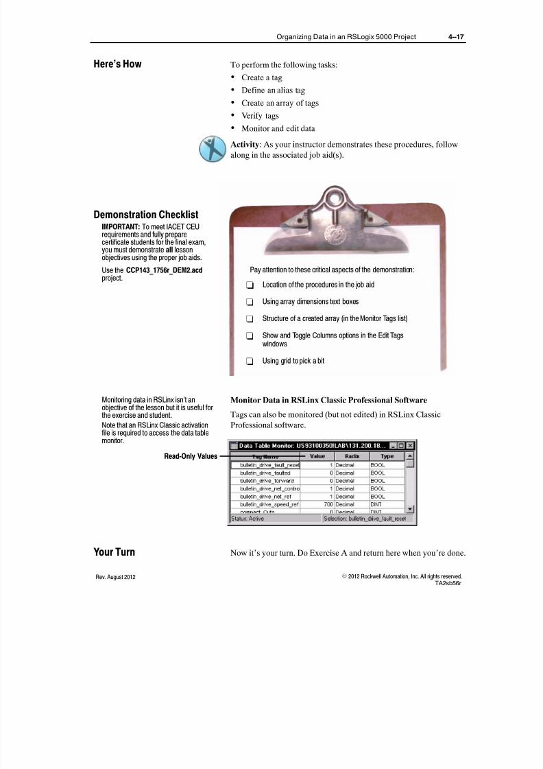
8/16/2019 Student Manual _ ABT-CCP-TSM143 _ RSLogix 5000, Level 3 _ Project Development.pdf
http://slidepdf.com/reader/full/student-manual-abt-ccp-tsm143-rslogix-5000-level-3-project-developmentpdf 89/375
4--17Organizing Data in an RSLogix 5000 Project
E 2012 Rockwell Automation, Inc. All rights reserved.Rev. August 2012TA2sb56r
To perform the following tasks:
Create a tag
Define an alias tag
Create an array of tags
Verify tags
Monitor and edit data
Activity: As your instructor demonstrates these procedures, follow
along in the associated job aid(s).
- Location of the procedures in the job aid
- Using array dimensions text boxes
- Structure of a created array (in the Monitor Tags list)
- Show and Toggle Columns options in the Edit Tagswindows
- Using grid to pick a bit
Pay attention to these critical aspects of the demonstration:
Monitor Data in RSLinx Classic Professional Software
Tags can also be monitored (but not edited) in RSLinx Classic
Professional software.
Read-Only Values
Now it’s your turn. Do Exercise A and return here when you’re done.
Here’s How
IMPORTANT: To meet IACET CEU
requirements and fully preparecertificate students for the final exam,you must demonstrate all lessonobjectives using the proper job aids.
Use the CCP143_1756r_DEM2.acdproject.
Demonstration Checklist
Monitoring data in RSLinx isn’t anobjective of the lesson but it is useful forthe exercise and student.
Note that an RSLinx Classic activationfile is required to access the data tablemonitor.
Your Turn

8/16/2019 Student Manual _ ABT-CCP-TSM143 _ RSLogix 5000, Level 3 _ Project Development.pdf
http://slidepdf.com/reader/full/student-manual-abt-ccp-tsm143-rslogix-5000-level-3-project-developmentpdf 90/375
4--18 Organizing Data in an RSLogix 5000 Project
E 2012 Rockwell Automation, Inc. All rights reserved. Rev. August 2012TA2sb56r
Data Access Control
The data access properties of a tag is used to control how people and
programs access the tag at run-time:
Use External Access to control how an external application, such
as an HMI, historian, or OPC data server, can access a tag:-- Arrays -- Top level only; UDTs -- by member
-- Possible values are:
-- Read/Write: External applications can both read and
modify the tag’s value
-- Read Only: External applications can read the tag’s value,
but not modify it
-- None: External applications can neither read nor write the
tag’s value
Use Constant to control how controller logic can access a tag:
-- When this attribute is set, the tag’s value cannot be changedprogrammatically
Data Access Control Selections are shown in the following graphic:
Data AccessControl Selections
Tags Window
User-DefinedData Type
Data Access Control Benefits
These options give you a way to protect data from being accidentally
or intentionally written to. They can also speed-up HMI creation by
reducing the number of tags that are visible while browsing the
controller from the HMI development environment.
Now it’s your turn. Do Exercise B.
Mention that External Access Control
does not apply to Module Defined tagsor aliases to them.
Mention that if a tag’s external access isset to None, the tag will not show up inother application browsers.Note that if a tag is set to Constant anda program instruction tries to write avalue to the tag, this would appear as anerror when verifying the project.
Your Turn

8/16/2019 Student Manual _ ABT-CCP-TSM143 _ RSLogix 5000, Level 3 _ Project Development.pdf
http://slidepdf.com/reader/full/student-manual-abt-ccp-tsm143-rslogix-5000-level-3-project-developmentpdf 91/375
4--19Exercise: Organizing Data in an RSLogix 5000 Project
E 2012 Rockwell Automation, Inc. All rights reserved.Rev. August 2012TA2e56r
Exercise: Organizing Data in anRSLogix 5000 Project
In this exercise, you will practice the following tasks: Creating a tag
Defining an alias tag
Creating an array of tags
Verifying tags
Monitoring and editing data
Context:
Sample code to test your production line has been developed. This
code was written before your hardware installation. The hard-wired
addresses were not known when the code was created. You now needto create base and alias tags and an array of tags so that the code will
function properly.
When you see underlined text, refer to the related procedure or
information in your job aid.
Directions:
1. Open the TA2_1756r_A1.acd file.
2. Review your project and verify the tags referenced in the
MainRoutine of the Line_1 program have not been created.
3. Create a new tag with the following properties:
Name: Stop_Motor
Type: Base
Data Type: BOOL
Scope: Program (Line_1)
4. Create a new alias tag with the following properties:
Name: Start_Motor
Type: Alias
Alias For: Local:2:I.Data.0
Scope: Program (Line_1)
5. Create a new alias tag with the following properties:
Name: Motor_On
Type: Alias
Alias For: Local:0:O.Data.0
Scope: Program (Line_1)
Exercise A

8/16/2019 Student Manual _ ABT-CCP-TSM143 _ RSLogix 5000, Level 3 _ Project Development.pdf
http://slidepdf.com/reader/full/student-manual-abt-ccp-tsm143-rslogix-5000-level-3-project-developmentpdf 92/375
4--20 Exercise: Organizing Data in an RSLogix 5000 Project
E 2012 Rockwell Automation, Inc. All rights reserved. Rev. August 2012TA2e56r
6. Create a new tag with the following properties:
Name: Motor_Time
Type: Base
Data Type: TIMER
Scope: Program (Line_1)
7. Within the Program Tags monitor, enter 10,000 for the
Motor_Time.PRE member of the Motor_Time tag.
8. Create a new alias tag with the following properties:
Name: Motor_Speed
Type: Alias
Alias For: Local:8:I.Ch0Data
Scope: Program (Line_1)
9. Create a new alias tag with the following properties:
Name: Speed_Out
Type: Alias
Alias For: Local:7:O.Ch0Data
Scope: Program (Line_1)
10. Create a single-dimension array that will be used to store the
system date and time. This array requires a separate element for
the system year, month, day, hour, minute, seconds, and
microseconds. Configure the array with the following properties:
Name: ClockTime
Type: Base
Data Type: DINT
Array Dimension 0: 7 elements
Scope: Controller
External Access: Read only
11. Download your project to the controller in slot 1 of your
workstation.
12. Place the controller in Run or Remote Run mode.
13. How could the individual members of this UDT be set so they
would not be accessible from any other application?

8/16/2019 Student Manual _ ABT-CCP-TSM143 _ RSLogix 5000, Level 3 _ Project Development.pdf
http://slidepdf.com/reader/full/student-manual-abt-ccp-tsm143-rslogix-5000-level-3-project-developmentpdf 93/375
4--21Exercise: Organizing Data in an RSLogix 5000 Project
E 2012 Rockwell Automation, Inc. All rights reserved.Rev. August 2012TA2e56r
14. Verify you properly created and aliased your tags by performing
the following actions:
A. Press DI0 and observe DO0 indicator light turn on.
B. Adjust pot AI0 and confirm potentiometer AO0 updates in
value while the motor is enabled.C. Confirm that after ten seconds indicator DO0 turns off.
D. Monitor the ClockTime array and verify the tag is populating
with system date and time information.
The system date and time may not be current.
15. Go offline and close your project.
Turn to the Answers section.
In this exercise, you will practice setting a tag’s external access
option, and verify the setting.
Context:
You have created and organized a project file for your production
lines. You now want to protect certain tags from outside access.
When you see underlined text, refer to the related procedure or
information in your job aid.
Directions:
1. Open the TA2_1756r_B1.acd file.
2. Download your project to the controller in slot 1.
3. Make sure your processor is in Run mode.
4. Monitor the ClockTime tag in RSLinx software and make sure
some of the data is changing.
5. Return to the RSLogix 5000 software and go offline.
6. In the Controller tags, set the ClockTime tag’s external access to
None.
7. Download your project to the controller in slot 1.
8. Is the ClockTime tag visible in RSLinx software?
Turn to the Answers section.
"Tip
How Did You Do?
Exercise B
How Did You Do?

8/16/2019 Student Manual _ ABT-CCP-TSM143 _ RSLogix 5000, Level 3 _ Project Development.pdf
http://slidepdf.com/reader/full/student-manual-abt-ccp-tsm143-rslogix-5000-level-3-project-developmentpdf 94/375
4--22 Exercise: Organizing Data in an RSLogix 5000 Project
E 2012 Rockwell Automation, Inc. All rights reserved. Rev. August 2012TA2e56r
Exercise A
3. Your Stop_Motor tag should have the following properties:
4. Your Start_Motor tag should have the following properties:
Answers

8/16/2019 Student Manual _ ABT-CCP-TSM143 _ RSLogix 5000, Level 3 _ Project Development.pdf
http://slidepdf.com/reader/full/student-manual-abt-ccp-tsm143-rslogix-5000-level-3-project-developmentpdf 95/375
4--23Exercise: Organizing Data in an RSLogix 5000 Project
E 2012 Rockwell Automation, Inc. All rights reserved.Rev. August 2012TA2e56r
5. Your Motor_On tag should have the following properties:
6. Your Motor_Time tag should have the following properties:
7. Your Motor_Time tag should be configured similar to the
following example:

8/16/2019 Student Manual _ ABT-CCP-TSM143 _ RSLogix 5000, Level 3 _ Project Development.pdf
http://slidepdf.com/reader/full/student-manual-abt-ccp-tsm143-rslogix-5000-level-3-project-developmentpdf 96/375
4--24 Exercise: Organizing Data in an RSLogix 5000 Project
E 2012 Rockwell Automation, Inc. All rights reserved. Rev. August 2012TA2e56r
8. Your Motor_Speed tag should have the following properties:
9. Your Speed_Out tag should have the following properties:
10. Your ClockTime tag should have the following properties:

8/16/2019 Student Manual _ ABT-CCP-TSM143 _ RSLogix 5000, Level 3 _ Project Development.pdf
http://slidepdf.com/reader/full/student-manual-abt-ccp-tsm143-rslogix-5000-level-3-project-developmentpdf 97/375
4--25Exercise: Organizing Data in an RSLogix 5000 Project
E 2012 Rockwell Automation, Inc. All rights reserved.Rev. August 2012TA2e56r
13. Set the external access to none.
14.
D. Your ClockTime tag should contain data in each member of
the array like the following example:
Exercise B
6. After setting the ClockTime tag’s external access to None, yourscreen should appear similar to the following:
8. No, the ClockTime tag is not visible. Your screen should appear
similar to the following:

8/16/2019 Student Manual _ ABT-CCP-TSM143 _ RSLogix 5000, Level 3 _ Project Development.pdf
http://slidepdf.com/reader/full/student-manual-abt-ccp-tsm143-rslogix-5000-level-3-project-developmentpdf 98/375
4--26 Exercise: Organizing Data in an RSLogix 5000 Project
E 2012 Rockwell Automation, Inc. All rights reserved. Rev. August 2012TA2e56r

8/16/2019 Student Manual _ ABT-CCP-TSM143 _ RSLogix 5000, Level 3 _ Project Development.pdf
http://slidepdf.com/reader/full/student-manual-abt-ccp-tsm143-rslogix-5000-level-3-project-developmentpdf 99/375
Lesson 5
E 2012 Rockwell Automation, Inc. All rights reserved.Rev. August 2012UDTsb56r
Creating a User-Defined Data Typein an RSLogix 5000 Project
After completing this lesson, you should be able to:
Create a user-defined data type
Export and import user-defined data types
When You Will Do This
As you develop your logic, you will typically take advantage of
user--defined data types to organize your data.
Creating a User-Defined Data Type
Some predefined data types, such as a TIMER, are structures of
several different data types:
Members of aTIMER Data Type
MixedDataTypes
Data Type
What You Will Learn
Before You Begin
Add that in RSLogix 5000 software,timers have some additional bits.
Note that in a PLC-5 controller, T4:5 hasits memory defined using the TIMERtemplate.

8/16/2019 Student Manual _ ABT-CCP-TSM143 _ RSLogix 5000, Level 3 _ Project Development.pdf
http://slidepdf.com/reader/full/student-manual-abt-ccp-tsm143-rslogix-5000-level-3-project-developmentpdf 100/375
5--2 Creating a User-Defined Data Type in an RSLogix 5000 Project
E 2012 Rockwell Automation, Inc. All rights reserved. Rev. August 2012UDTsb56r
User-Defined Data Type: A structure created by a user to group
data in an application.
Member: One defined data type within the structure.
Example: User-Defined Data TypeThere are several identical tanks in a plant. Each tank stores data
for the following values:
Temperature
Steam Valve State
Level
Time over Temperature
To store this data, a user-defined data type can be created. The
data type is a template for storing the information:
Members ofTank Structure
Size
ExternalAccessSettings
A tag for each tank can be created using this user-defined data
type.
Review: An element is one part of anarray.
A member is one part of a data type.
Chalk Talk: Before showing the nextslide, have the students help you makea list of the members that might go intothe user-defined data type for the tankexample. Have the students select thedata type of each member.
Add that this is a more efficient use ofmemory than creating a single BOOL forthe steam valve, as the single BOOL would use a DINT (32 bits) by itself.
Provide other examples, includingexamples of recipe parameters andstorage data types.
Note that creating an array is easier thancreating 20 individual tags.

8/16/2019 Student Manual _ ABT-CCP-TSM143 _ RSLogix 5000, Level 3 _ Project Development.pdf
http://slidepdf.com/reader/full/student-manual-abt-ccp-tsm143-rslogix-5000-level-3-project-developmentpdf 101/375
5--3Creating a User-Defined Data Type in an RSLogix 5000 Project
E 2012 Rockwell Automation, Inc. All rights reserved.Rev. August 2012UDTsb56r
Example: Arrays and User-Defined Data Types
If there are 25 tanks (5 rows of 5), a programmer can make an
array of tags that uses a user-defined data type:
Tank [0,0] Total Array = [5,5]
One Specific Element = Tank[1,3]
User-Defined Data Type ParametersTo create a user-defined data type, you must define the following
parameters for each member:
A name of up to a maximum of 40 characters
A display style
A description (optional)
One of the following data types:
-- Any pre-defined data type
-- Another user-defined data type
-- Single-dimension array of any pre-defined data types
-- Single-dimension array of any user-defined data types
The memory required by a user-defined data type depends on the
number of members, the data type for each member, and how the
members are organized.
User-Defined Data Type Addressing
Just as you addressed TIMER members in other projects (T4.EN or
T4.TT), you can address members of a user-defined structure using
the following addressing structure:
Tag.Member
Examples: User-Defined Data Type Addressing
SystemTimer.Pre
WaterTank.Level
Input_Location.Load_Info.Height
Note that in this scenario, theuser-defined data type is created first,and then the array of tags is created.
Stress that arrays embedded within auser-defined data type can only haveone dimension.
Note that memory size is updated aftereach member is added and accepted inthe software’s Edit Data Type dialog box.
Chalk Talk: On the board, write thefollowing data types in order: BOOL,DINT, and then a BOOL. Discuss howthis structure would take more memorythan the DINT followed by both BOOLs.
Add some additional examples.
Note that this is similar to how youaddress TIMER members in otherprojects (T4.EN or T4.TT).
State that the delimiter is a period.
Point out that the last example containsa structure (Load_Info) that is embeddedin the user-defined data type.

8/16/2019 Student Manual _ ABT-CCP-TSM143 _ RSLogix 5000, Level 3 _ Project Development.pdf
http://slidepdf.com/reader/full/student-manual-abt-ccp-tsm143-rslogix-5000-level-3-project-developmentpdf 102/375
5--4 Creating a User-Defined Data Type in an RSLogix 5000 Project
E 2012 Rockwell Automation, Inc. All rights reserved. Rev. August 2012UDTsb56r
Exporting and Importing User-Defined Data Types
Exporting and importing allows you to have more flexibility in your
programming and creates a user-defined data that:
Is easy to deploy
Creates reusable programming code
When you export a user-defined data type to an .L5X file, the file
contains the definition and any references to the project.
Export a UDT
using a .L5X File
Importing a user-defined data type allows you to perform several
edits in one operation.
When you import a user-defined data type, you can:
Import offline or online (including Remote Run mode)
Import into the same project or different one
Create a new user-defined data type
Update an existing user-defined data type
Import a UDTinto the same or
new project
Obtaincollisioninformation
Specify finalname

8/16/2019 Student Manual _ ABT-CCP-TSM143 _ RSLogix 5000, Level 3 _ Project Development.pdf
http://slidepdf.com/reader/full/student-manual-abt-ccp-tsm143-rslogix-5000-level-3-project-developmentpdf 103/375
5--5Creating a User-Defined Data Type in an RSLogix 5000 Project
E 2012 Rockwell Automation, Inc. All rights reserved.Rev. August 2012UDTsb56r
To perform the following tasks:
Create a user-defined data type
Export and import user-defined data types
Activity: As your instructor demonstrates these procedures, follow
along in the associated job aid(s).
- Location of the procedures in the job aid
- Location of the procedures in the Start Pages
- Difference between a user--defined data type and anarray
- Overwriting a user--defined data type with a newerversion
Pay attention to these critical aspects of the demonstration:
Here’s How
IMPORTANT: To meet IACET CEUrequirements and fully preparecertificate students for the final exam,you must demonstrate all lessonobjectives using the proper job aids.
Use the steps below to help guide youduring the demonstration:
Open the Start Pages and use thefollowing tools to demonstrate each task:
S How Do I" Tags, Data Types &Other Data" Create aUser-Defined Type
S What’s New" Import Online -Programs, Routine and Instructions
S If the Start Pages are unavailable orif students prefer, use theCCP143_1756r_DEM2.acd project.
Demonstration Checklist

8/16/2019 Student Manual _ ABT-CCP-TSM143 _ RSLogix 5000, Level 3 _ Project Development.pdf
http://slidepdf.com/reader/full/student-manual-abt-ccp-tsm143-rslogix-5000-level-3-project-developmentpdf 104/375
5--6 Creating a User-Defined Data Type in an RSLogix 5000 Project
E 2012 Rockwell Automation, Inc. All rights reserved. Rev. August 2012UDTsb56r

8/16/2019 Student Manual _ ABT-CCP-TSM143 _ RSLogix 5000, Level 3 _ Project Development.pdf
http://slidepdf.com/reader/full/student-manual-abt-ccp-tsm143-rslogix-5000-level-3-project-developmentpdf 105/375
5--7Exercise: Creating a User-Defined Data Type in an RSLogix 5000 Project
E 2012 Rockwell Automation, Inc. All rights reserved.Rev. August 2012UDTe56r
Exercise: Creating a User-DefinedData Type in an RSLogix 5000Project
In this exercise, you will practice the following tasks:
Create a user-defined data type
Export and import user-defined data types
Context:
You have just created and organized a project file for your line 1
production line. You are now ready to develop code for a second,
identical, production line. Your application requires that you store
each production line’s output information in user-defined tags.
When you see underlined text, refer to the related procedure or
information in your job aid.
Directions:
1. Open the UDT_1756r_A1.acd file.
2. Create a UDT named Motor_Status with the following
members:
Name Data Type
Active BOOL
Fault BOOL ProcessTime DINT
MotorSpeed REAL
3. Create a new tag with the following properties:
Name: Line_1
Type: Base
Data Type: Motor_Status
Scope: Controller
4. Open MainRoutine within the Line_1 program.
5. Modify rung 4 so that member Line_1.Active is the operand of the OTE instruction.
6. Modify rung 5 so that member Line_1.ProcessTime is the
Destination operand of the Move instruction.
7. Modify rung 6 so that member Line_1.MotorSpeed is the
Destination operand of the Move instruction.
Exercise A

8/16/2019 Student Manual _ ABT-CCP-TSM143 _ RSLogix 5000, Level 3 _ Project Development.pdf
http://slidepdf.com/reader/full/student-manual-abt-ccp-tsm143-rslogix-5000-level-3-project-developmentpdf 106/375
5--8 Exercise: Creating a User-Defined Data Type in an RSLogix 5000 Project
E 2012 Rockwell Automation, Inc. All rights reserved. Rev. August 2012UDTe56r
8. Create a new tag with the following properties:
Name: Line_2
Type: Base
Data Type: Motor_Status
Scope: Controller
9. Open MainRoutine within the Line_2 program.
10. Modify rung 4 so that member Line_2.Active is the operand of
the OTE instruction.
11. Modify rung 5 so that member Line_2.ProcessTime is the
Destination operand of the Move instruction.
12. Modify rung 6 so that member Line_2.MotorSpeed is the
Destination operand of the Move instruction.
13. Download your project to the controller in slot 1 of your
workstation.
14. Place the controller in Run or Remote Run mode.
15. Verify you properly created your UDT tags by monitoring them
and confirming they update in value when Lines 1 and 2 are
operating.
16. Export the Motor_Status user-defined data type project
component.
17. Go offline.
18. Open the UDT_1756r_A2.acd file.
19. Import the Motor_Status user-defined data type project
component into the UDT_1756r_A2.acd project.
20. From the Import Collision dialog box, click Collision Details.
21. What information changed in the imported UDT?
22. Click Close.23. Overwrite the existing Motor_Status UDT and keep the same
final name.
24. Click OK .

8/16/2019 Student Manual _ ABT-CCP-TSM143 _ RSLogix 5000, Level 3 _ Project Development.pdf
http://slidepdf.com/reader/full/student-manual-abt-ccp-tsm143-rslogix-5000-level-3-project-developmentpdf 107/375
5--9Exercise: Creating a User-Defined Data Type in an RSLogix 5000 Project
E 2012 Rockwell Automation, Inc. All rights reserved.Rev. August 2012UDTe56r
25. Create a new tag with the following properties:
Name: Line_3
Type: Base
Data Type: Motor_Status
Scope: Controller
26. Open MainRoutine within the Line_3 program.
27. Modify rung 4 so that member Line_3.Active is the operand of
the OTE instruction.
28. Modify rung 5 so that member Line_3.ProcessTime is the
Destination operand of the Move instruction.
29. Modify rung 6 so that member Line_3.MotorSpeed is the
Destination operand of the Move instruction.
30. Download your project to the controller in slot 1 of your
workstation.
31. Place the controller in Run or Remote Run mode.
32. Verify you properly created your UDT tags by monitoring them
and confirming they update in value when Line 3 is operating.
33. Go offline and close your projects.
Turn to the Answers section.How Did You Do?

8/16/2019 Student Manual _ ABT-CCP-TSM143 _ RSLogix 5000, Level 3 _ Project Development.pdf
http://slidepdf.com/reader/full/student-manual-abt-ccp-tsm143-rslogix-5000-level-3-project-developmentpdf 108/375
5--10 Exercise: Creating a User-Defined Data Type in an RSLogix 5000 Project
E 2012 Rockwell Automation, Inc. All rights reserved. Rev. August 2012UDTe56r
Exercise A
2. Your Motor_Status UDT should look similar to the following
example:
7. Rungs 4--6 of the MainRoutine in the Line_1 program should
now look similar to the following example:
Answers

8/16/2019 Student Manual _ ABT-CCP-TSM143 _ RSLogix 5000, Level 3 _ Project Development.pdf
http://slidepdf.com/reader/full/student-manual-abt-ccp-tsm143-rslogix-5000-level-3-project-developmentpdf 109/375
5--11Exercise: Creating a User-Defined Data Type in an RSLogix 5000 Project
E 2012 Rockwell Automation, Inc. All rights reserved.Rev. August 2012UDTe56r
12. Rungs 4--6 of the MainRoutine in the Line_2 program should
now look similar to the following example:
21. The data type size and the structure changed.
23. You should have configured the imported UDT as follows:

8/16/2019 Student Manual _ ABT-CCP-TSM143 _ RSLogix 5000, Level 3 _ Project Development.pdf
http://slidepdf.com/reader/full/student-manual-abt-ccp-tsm143-rslogix-5000-level-3-project-developmentpdf 110/375
5--12 Exercise: Creating a User-Defined Data Type in an RSLogix 5000 Project
E 2012 Rockwell Automation, Inc. All rights reserved. Rev. August 2012UDTe56r
29. Rungs 4--6 of the MainRoutine in the Line_3 program should
now look similar to the following example:

8/16/2019 Student Manual _ ABT-CCP-TSM143 _ RSLogix 5000, Level 3 _ Project Development.pdf
http://slidepdf.com/reader/full/student-manual-abt-ccp-tsm143-rslogix-5000-level-3-project-developmentpdf 111/375
Lesson 6
E 2012 Rockwell Automation, Inc. All rights reserved.Rev. August 2012EN2sb56r
Entering, Editing, and VerifyingLadder Logic in an RSLogix 5000Project
After completing this lesson, you should be able to:
Enter and edit ladder Logic using ASCII mnemonics
Configure ladder logic quick keys
Copy and reuse ladder logic components
Verify a project or a project component (online)
When You Will Do This
Once you have laid out your task and program structure and defined
your data types, you can begin to develop your ladder logic.
Entering and Editing Ladder Logic Components
The RSLogix series of software offers the ability to enter or edit
ladder logic using the following basic methods:
Dragging method
Right-click/Insert key
The RSLogix series of software also offers faster methods for more
proficient programmers:
ASCII mnemonic editing
Quick keys
Note that this lesson briefly reviewssome concepts from the prerequisitecourse before presenting moreadvanced concepts such as Quick Keys.Tailor this lesson as needed.
What You Will LearnPoll the students to see how many haveexperience using a Window’s-basedprogramming software from their job, orpre-requisite classes.
Pace this lesson based on the generalexperience level of your class.
Describe which method you personallyfind to be fastest and/or easiest whenentering ladder logic.
Before You Begin
Review the first two methods if needed.Students should be familiar with these.

8/16/2019 Student Manual _ ABT-CCP-TSM143 _ RSLogix 5000, Level 3 _ Project Development.pdf
http://slidepdf.com/reader/full/student-manual-abt-ccp-tsm143-rslogix-5000-level-3-project-developmentpdf 112/375
6--2 Entering, Editing, and Verifying Ladder Logic in an RSLogix 5000 Project
E 2012 Rockwell Automation, Inc. All rights reserved. Rev. August 2012EN2sb56r
ASCII Mnemonic Editing
ASCII mnemonics are text codes that represent instructions and
ladder logic elements:
ASCII TextEntry Line
GraphicalLadderLogic
In the graphic, note the following items:
The mnemonics are entered, followed by the tag to be operated
on or a “?” or a space.
Start and end points for branches can also be entered:
-- BST (Branch start)
-- NXB (Next Branch)
-- BND (Branch End)
Configuring Ladder Logic Quick Keys
To quickly enter instructions and other ladder logic elements using
single keyboard keys, assign quick keys:
Quick keys for several common instructions including XIC, XIO,
and OTE are already assigned. Quick keys must be enabled to be used.
Copying and Reusing Ladder Logic Components
If ladder logic contains program-scoped tags, the ladder logic can be
easily copied and reused in different programs without changing the
tag names.
State that ASCII stands for the AmericanStandards Code for InformationExchange.
Read each mnemonic in the graphic andshow the corresponding graphicalelement.
Note that unlike RSLogix 5 and 500software, in RSLogix 5000 the ASCII lineis not highlighted by default andtherefore more difficult to accidentallyerase.
Point out that Quick Keys are enabled inthe Options for the Ladder Editor. Thisstep is included in the procedure in theProcedures Guide.
Describe examples of real applications,such as auto production lines, wherecommon machine cells are repeated.

8/16/2019 Student Manual _ ABT-CCP-TSM143 _ RSLogix 5000, Level 3 _ Project Development.pdf
http://slidepdf.com/reader/full/student-manual-abt-ccp-tsm143-rslogix-5000-level-3-project-developmentpdf 113/375
6--3Entering, Editing, and Verifying Ladder Logic in an RSLogix 5000 Project
E 2012 Rockwell Automation, Inc. All rights reserved.Rev. August 2012EN2sb56r
Example: Copied Ladder Logic
Because the programs are local, the same ladder logic and the
tags (e.g., Station_Timer) can be copied to all programs.
SameProgram_Scoped
Tag Name
SameProgram_Scoped
Tag Name
Different Program
Easy Copy and Paste
The tags within the program are commonly aliastags for different I/O points.
Remember that controller-scoped tags are sharedby all programs. Be careful when accessing thesame controller-scoped tag from differentroutines.

8/16/2019 Student Manual _ ABT-CCP-TSM143 _ RSLogix 5000, Level 3 _ Project Development.pdf
http://slidepdf.com/reader/full/student-manual-abt-ccp-tsm143-rslogix-5000-level-3-project-developmentpdf 114/375
6--4 Entering, Editing, and Verifying Ladder Logic in an RSLogix 5000 Project
E 2012 Rockwell Automation, Inc. All rights reserved. Rev. August 2012EN2sb56r
Other Short-Cuts
These additional methods will also make you a more efficient
programmer:
RSLogix 5000 software also offers the ability to open a second
instance of the software:
-- This allows you to easily copy and paste ladder logic between
two open files.
For ladder logic and structured text, you can save instruction
defaults:
-- These defaults are saved to the computer and apply to all
projects opened on the computer.
Verifying a Project or a Project Component Online
Modifying code online can help you quickly make changes without
stopping production.
Online Safety Warning
When editing ladder logic online, keep the following warning in
mind:
Use extreme caution when entering or editingladder logic or data, forcing values, or making otherchanges online that will affect the control of devices. Mistakes can cause unintended machine
motion or loss of process control, possibly injuringpersonnel and damaging equipment. Beforeperforming procedures online, complete these safetyprecautions:
Determine if changes must be made online.
Verify that your company permits online
entering and editing.
Assess how machinery will respond to changes.
Check proposed changes for accuracy.
Notify all personnel of the changes.
Verify that you are online to the correct
controller.
Because changes in any online mode can affectmachine and process control, before enteringladder logic, verify the current communicationsmode using the Online toolbar.
State that up to four instances of thesoftware can be opened at one time.
Note that you can also copy from onefile, close the file, open a different file,and then paste into the other file. Thecopied information is maintainedon the clipboard.
Describe any real-world situations thatyou are aware of in which online editingcaused extensive damage in a plant.
? Define offline and online?
Answer: Offline means that theworkstation (computer) is displaying acopy of the project stored in thecomputer memory only. Online meansthat the workstation (computer) isdisplaying and changing copy of theproject stored in the controller memory.
Add that the Online graphic is animatedin any online mode.
Also note that the left and right powerrails are illuminated in green in theonline mode to indicate that the ladderlogic is being executed.

8/16/2019 Student Manual _ ABT-CCP-TSM143 _ RSLogix 5000, Level 3 _ Project Development.pdf
http://slidepdf.com/reader/full/student-manual-abt-ccp-tsm143-rslogix-5000-level-3-project-developmentpdf 115/375
6--5Entering, Editing, and Verifying Ladder Logic in an RSLogix 5000 Project
E 2012 Rockwell Automation, Inc. All rights reserved.Rev. August 2012EN2sb56r
Performing Online Ladder Logic Edits
Editing ladder logic elements online requires different steps in
different modes:
When editing in
this mode . . .
You must perform the
following actions . . . Description . . .
Online in the Remote
Program mode
Start edits
Routine(s) edits exist only in the
computer. Necessary when changing
an existing rung, but not necessary to
add a new rung.
Verify edits
The project is examined for errors.
Verification can be done separately or
automatically if you skip to the Accept
edits step.
Accept edits The revised routine(s) are transferred
to the controller.
Online in the Remote
Run mode
Start edits
Routine(s) edits exist only in the
computer. Necessary when changing
an existing rung, but not necessary to
add a new rung.
Verify edits
The project is examined for errors.
Verification can be done separately or
automatically if you skip to the Accept
edits step.
Accept edits
The revised routine(s) are transferred
to the controller but the previous
program continues to execute.
Test edits
The revised routine(s) executes,
controlling the physical outputs, but the
previous program still exists in the
controller. You can return to theprevious program using Untest edits.
Assemble edits
The previous routine(s) language is
discarded and the revised program
continues executing.
Online verification buttons can be used to complete this process:
Cancel Pending Rung Edit
Single-Rung Options Program-Level Options
Finalize Edits Option
Verify Open Routine VerifyController
Standard Toolbar
Online Edit Toolbar
Use tooltips to identify the buttons.
State that the additional online steps are
another reason that online editing isslower and more difficult. The extrasteps are in place for user safety.
Tell students that the Verify edits stepcan be considered optional since theverification process will automaticallytake place with the Accept edits step.
State that “accept” puts the change intothe controller memory.
Important: Stress the differencebetween controller Remote Test mode(outputs set according to Program modestate) and the Test edits step in Verify,
Accept, Test, Assemble (outputsscanned and set using the program).Program mode state is set in the outputmodule configuration.
If students are interested, review thenames of all of the buttons during thedemonstration using the Tooltips.
"Tip

8/16/2019 Student Manual _ ABT-CCP-TSM143 _ RSLogix 5000, Level 3 _ Project Development.pdf
http://slidepdf.com/reader/full/student-manual-abt-ccp-tsm143-rslogix-5000-level-3-project-developmentpdf 116/375
6--6 Entering, Editing, and Verifying Ladder Logic in an RSLogix 5000 Project
E 2012 Rockwell Automation, Inc. All rights reserved. Rev. August 2012EN2sb56r
When verifying, the software looks for the following errors:
Improper instruction placement
Improper or incomplete addressing
Tags with an invalid data type for the instruction (mismatches)
Improper tag creation
Empty rungs
Shorted branches (reported in error tab as a warning)
Duplicate destructive bits (reported in error tab as a warning)
The duplicate destructive bit option looks forinstructions that modify the same bit. Thisincludes instructions such as OTE, ONS, OSF,and OSR instructions in ladder logic. This optionis enabled by default.
Presence of Always False Instruction (AFI) (reported in error tab
as a warning)
Presence of forces (reported in error tab as a warning)
Auto Rung Verification: An option that can be enabled to
automatically verify a rung.
Errors found in the verification process are displayed on the Errors
tab of the Output window:
Double-Click toGo to the Error orPress F4
Finalize Edits Option
The Finalize Edits option allows you to complete online edits in one
step.
For equipment and personnel safety, the fullsequence of steps (verify, accept, test, assemble)should be used as it requires the programmers tocheck the steps and test them before assemblingthem in the controller. The Finalize Edits optionshould be reserved for changes that will not impactsafety.
For the invalid data type error, clarifythat a tag of the DINT data type cannotbe used in an XIC bit instruction unless itis specified to the bit level (e.g., DINT.0and not just DINT).
Point out that this option can be enabledusing ToolsOptions.
Mention that this is known as “duplicateOTE detection” in PLC/SLC processors.
Note that this also includes bits used inother languages, such as OREFs inFBD, bits in transitions in SFCs, and bit
assignments in ST.
Note that this is an option foundin the ToolsOptions dialog box.
Point out some benefits of this option:
S Fewer steps required to go fromchange to running code
S Reduces system startup time byeliminating delays
Compare these benefits to some of theinherit risks.

8/16/2019 Student Manual _ ABT-CCP-TSM143 _ RSLogix 5000, Level 3 _ Project Development.pdf
http://slidepdf.com/reader/full/student-manual-abt-ccp-tsm143-rslogix-5000-level-3-project-developmentpdf 117/375
6--7Entering, Editing, and Verifying Ladder Logic in an RSLogix 5000 Project
E 2012 Rockwell Automation, Inc. All rights reserved.Rev. August 2012EN2sb56r
Edit Zone Markers
When you start editing online, a duplicate rung is displayed:
Edit Rung
Original Rung(Active in Controller)
Rung numbers after the edit are temporarily
changed while the edit rung is being modified.
During the editing and verifying process edit zone markers indicate
the type of edit that is being performed:
Once the edit in Remote Run mode is acceptedinto the controller memory, the markers change touppercase letters.
The following table summarizes the zone markers and their
meanings:
Zone Marker Description
Lowercase
e Rung of ladder logic that is currently edited within
the computer RAM
i Rung of ladder logic that is to be inserted
r Rung of ladder logic that is to be replaced
Uppercase (in
controller
memory)
I Rung of ladder logic that will be inserted
R Rung of ladder logic that is going to be replaced by
the rung directly above it
D Rung of ladder logic that is marked for deletion
Poll the students to see if they are awareof online editing policies in their owncompanies.
Mention that an asterisk “:” on anyinstruction, tab, etc., indicates that theelement has been edited but not yetaccepted.
Note that these markers are the sameas the edit markers in RSLogix 5 and500 software.
Point out that for reference, thisinformation is in the Procedures GuideGlossary under the term “Edit Zones.”
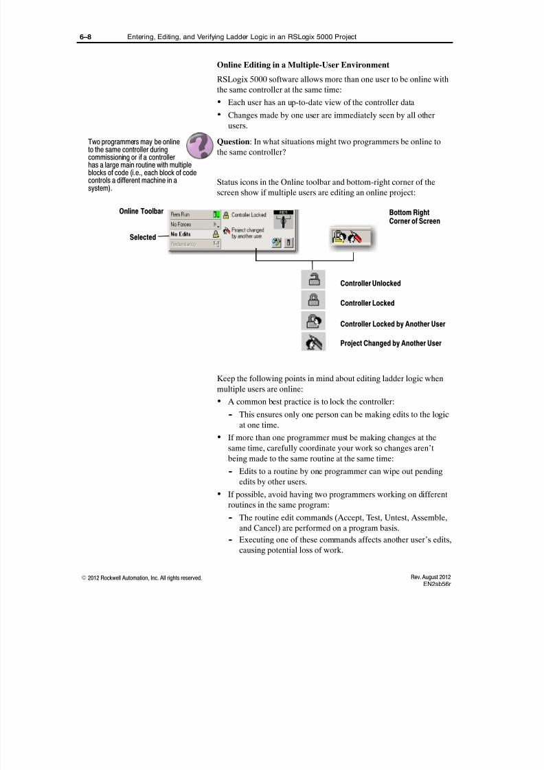
8/16/2019 Student Manual _ ABT-CCP-TSM143 _ RSLogix 5000, Level 3 _ Project Development.pdf
http://slidepdf.com/reader/full/student-manual-abt-ccp-tsm143-rslogix-5000-level-3-project-developmentpdf 118/375
6--8 Entering, Editing, and Verifying Ladder Logic in an RSLogix 5000 Project
E 2012 Rockwell Automation, Inc. All rights reserved. Rev. August 2012EN2sb56r
Online Editing in a Multiple-User Environment
RSLogix 5000 software allows more than one user to be online with
the same controller at the same time:
Each user has an up-to-date view of the controller data
Changes made by one user are immediately seen by all otherusers.
Question: In what situations might two programmers be online to
the same controller?
Status icons in the Online toolbar and bottom-right corner of the
screen show if multiple users are editing an online project:
Controller Locked
Controller Unlocked
Controller Locked by Another User
Project Changed by Another User
Selected
Bottom RightCorner of Screen
Online Toolbar
Keep the following points in mind about editing ladder logic when
multiple users are online:
A common best practice is to lock the controller:
-- This ensures only one person can be making edits to the logic
at one time.
If more than one programmer must be making changes at the
same time, carefully coordinate your work so changes aren’t
being made to the same routine at the same time:
-- Edits to a routine by one programmer can wipe out pendingedits by other users.
If possible, avoid having two programmers working on different
routines in the same program:
-- The routine edit commands (Accept, Test, Untest, Assemble,
and Cancel) are performed on a program basis.
-- Executing one of these commands affects another user’s edits,
causing potential loss of work.
Two programmers may be onlineto the same controller duringcommissioning or if a controllerhas a large main routine with multipleblocks of code (i.e., each block of codecontrols a different machine in asystem).

8/16/2019 Student Manual _ ABT-CCP-TSM143 _ RSLogix 5000, Level 3 _ Project Development.pdf
http://slidepdf.com/reader/full/student-manual-abt-ccp-tsm143-rslogix-5000-level-3-project-developmentpdf 119/375
6--9Entering, Editing, and Verifying Ladder Logic in an RSLogix 5000 Project
E 2012 Rockwell Automation, Inc. All rights reserved.Rev. August 2012EN2sb56r
To enter ladder logic by performing the following tasks:
Enter and edit ladder Logic using ASCII mnemonics
Configure ladder logic quick keys
Copy and reuse ladder logic components
Verify a project or a project component (online)
Activity: As your instructor demonstrates these procedures, follow
along in the associated job aid(s).
- Location of the procedures in the job aid
- Entering logic using the ASCII text editor
- Online verification buttons
- Locking the controller
Pay attention to these critical aspects of the demonstration:
Here’s How
IMPORTANT: To meet IACET CEUrequirements and fully preparecertificate students for the final exam,
you must demonstrate all lessonobjectives using the proper job aids.
Use the CCP143_1756r_DEM2.acdproject during the demonstration:
" To copy and reuse rungs,instructions, and branches, refer tothe Copying and Reusing ProjectComponents procedure.
Demonstration Checklist

8/16/2019 Student Manual _ ABT-CCP-TSM143 _ RSLogix 5000, Level 3 _ Project Development.pdf
http://slidepdf.com/reader/full/student-manual-abt-ccp-tsm143-rslogix-5000-level-3-project-developmentpdf 120/375
6--10 Entering, Editing, and Verifying Ladder Logic in an RSLogix 5000 Project
E 2012 Rockwell Automation, Inc. All rights reserved. Rev. August 2012EN2sb56r

8/16/2019 Student Manual _ ABT-CCP-TSM143 _ RSLogix 5000, Level 3 _ Project Development.pdf
http://slidepdf.com/reader/full/student-manual-abt-ccp-tsm143-rslogix-5000-level-3-project-developmentpdf 121/375
6--11Exercise: Entering, Editing, and Verifying Ladder Logic in an RSLogix 5000 Project
E 2012 Rockwell Automation, Inc. All rights reserved.Rev. August 2012EN2e56r
Exercise: Entering, Editing, and Verifying Ladder Logic in anRSLogix 5000 Project
In this exercise, you will practice entering, editing, and verifying
ladder logic in an RSLogix 5000 project.
Context:
You have been asked to add the ladder logic that will be used to
control the sequential portion of your application to an existing
project.
When you see underlined text, refer to the related procedure or
information in your job aid.
Directions:
1. Open the EN2_1756r_A1.acd file.
2. Download the project and then change the controller to Remote
Run mode.
3. Lock the controller to prevent other users from making online
changes to your project.
4. Open SecondaryRoutine and perform the following actions:
A. Using any method you choose, create the following ladder
logic:
If the value from AI0 is greater than 500, turn on DO0.
B. Assign the existing AI0 and DO0 tags to the logic
components.
C. Verify the rung (online).
D. Test the operation by setting analog input 0 (AI0) to a value
over 500.
E. Check that digital output 0 (DO0) turns on. If not, return andmodify your work.
Exercise A

8/16/2019 Student Manual _ ABT-CCP-TSM143 _ RSLogix 5000, Level 3 _ Project Development.pdf
http://slidepdf.com/reader/full/student-manual-abt-ccp-tsm143-rslogix-5000-level-3-project-developmentpdf 122/375
6--12 Exercise: Entering, Editing, and Verifying Ladder Logic in an RSLogix 5000 Project
E 2012 Rockwell Automation, Inc. All rights reserved. Rev. August 2012EN2e56r
F. Use the ASCII mnemonic editing method to enter the
following rung:
G. What does your ASCII text entry line look like for this rung?
(What syntax did you use?)
H. Save and accept the edits and test for proper operation of this
rung.
I. Test the operation by setting analog input 0 (AI0) to a value
between 100 and 200.
J. Check that digital output 0 (DO1) turns on. If not, return and
modify your work.
K. Once your work is correct, turn analog input 0 all the way to
the left to shut off the light.
L. Copy the rung you created in step 4. A. and reuse it to
program the following logic, modifying the rung as
necessary:
If the value from AI0 exceeds 700, turn on DO2.
M. Save the edits.
N. Test the operation by setting analog input 0 (AI0) to a value
over 700.
O. Check that digital output 2 (DO2) turns on. If not, return and
modify your work.
P. Enable the quick keys.

8/16/2019 Student Manual _ ABT-CCP-TSM143 _ RSLogix 5000, Level 3 _ Project Development.pdf
http://slidepdf.com/reader/full/student-manual-abt-ccp-tsm143-rslogix-5000-level-3-project-developmentpdf 123/375
6--13Exercise: Entering, Editing, and Verifying Ladder Logic in an RSLogix 5000 Project
E 2012 Rockwell Automation, Inc. All rights reserved.Rev. August 2012EN2e56r
Q. Configure the F5 key to be the RUNG (Start of Rung -- End
of Rung) command.
R. Using the quick key method, create the following logic and
necessary tags:
If DO0 has been on for three seconds, turn on DO3. If DO0is turned off, DO3 turns off as well.
S. Save and accept the edits and test for proper operation of
your rung.
T. Are any of these cases where you could use the Finalize Edits
option? Why or why not?
5. When you are finished editing the program, unlock the controller.
Turn to the Answers section.How Did You Do?

8/16/2019 Student Manual _ ABT-CCP-TSM143 _ RSLogix 5000, Level 3 _ Project Development.pdf
http://slidepdf.com/reader/full/student-manual-abt-ccp-tsm143-rslogix-5000-level-3-project-developmentpdf 124/375
6--14 Exercise: Entering, Editing, and Verifying Ladder Logic in an RSLogix 5000 Project
E 2012 Rockwell Automation, Inc. All rights reserved. Rev. August 2012EN2e56r
Exercise A
4.
A. The rung should look similar to the following example:
G. BST LIM 100 AI0 200 NXB EQU AI0 300 BND OTE DO1
L. The rung should look similar to the following example:
P. To enable the quick keys, from the Tools menu, perform the
following actions:
-- Select Options Ladder Editor.
-- Select the Enable Quick Key check box.
-- Select the Show Quick Key Configuration check box.
Answers

8/16/2019 Student Manual _ ABT-CCP-TSM143 _ RSLogix 5000, Level 3 _ Project Development.pdf
http://slidepdf.com/reader/full/student-manual-abt-ccp-tsm143-rslogix-5000-level-3-project-developmentpdf 125/375
6--15Exercise: Entering, Editing, and Verifying Ladder Logic in an RSLogix 5000 Project
E 2012 Rockwell Automation, Inc. All rights reserved.Rev. August 2012EN2e56r
Q. To assign F5 as the SOR command, perform the following
actions:
-- On the Workstation Options Ladder Editor window, click
the Configure button.
-- Scroll to F5 and then double-click _Free.
-- From the drop-down list, select Rung.
R. The rungs should look similar to the following example:
T. The Finalize Edits option should only be used when there is
no safety concern. If this indicator light is not a safety-related
indicator, the Finalize Edits option could be used.

8/16/2019 Student Manual _ ABT-CCP-TSM143 _ RSLogix 5000, Level 3 _ Project Development.pdf
http://slidepdf.com/reader/full/student-manual-abt-ccp-tsm143-rslogix-5000-level-3-project-developmentpdf 126/375
6--16 Exercise: Entering, Editing, and Verifying Ladder Logic in an RSLogix 5000 Project
E 2012 Rockwell Automation, Inc. All rights reserved. Rev. August 2012EN2e56r

8/16/2019 Student Manual _ ABT-CCP-TSM143 _ RSLogix 5000, Level 3 _ Project Development.pdf
http://slidepdf.com/reader/full/student-manual-abt-ccp-tsm143-rslogix-5000-level-3-project-developmentpdf 127/375
Lesson 7
E 2012 Rockwell Automation, Inc. All rights reserved.Rev. August 2012IO2sb56r
Communicating with a Local1756-I/O Module
After completing this lesson, you should be able to manually add a
1756-I/O module to an I/O configuration.
When You Will Do This
You can add your I/O modules to your project before, during, or after
you develop your application logic. At some point though, you have
to add the I/O modules so you can link your logic to specific devices.
Reference: RSLogix 5000 and Logix5000 Procedures Guide
1. Find the Adding a Local or Remote 1756--I/O Module to an I/O
Configuration procedure in your procedures guide.
2. Briefly read the Get Ready steps.
Question: What does the term local I/O mean? Remote I/O?
Question: When do you usually add I/O modules to your projects?
Question: Are the modules usually installed at that point? Do youusually have access to them?
Electronic Keying
Before you add an I/O module, plan your electronic keying:
Electronic Keyingand Revision Level
What You Will Learn
In this lesson you’ll focus onadding local modules.
Point out that in this lesson you’llmanually add the modules.
Before You Begin

8/16/2019 Student Manual _ ABT-CCP-TSM143 _ RSLogix 5000, Level 3 _ Project Development.pdf
http://slidepdf.com/reader/full/student-manual-abt-ccp-tsm143-rslogix-5000-level-3-project-developmentpdf 128/375
7--2 Communicating with a Local 1756-I/O Module
E 2012 Rockwell Automation, Inc. All rights reserved. Rev. August 2012IO2sb56r
The electronic keying feature:
Automatically compares the expected module (as shown in the
I/O Configuration tree) to the physical module before I/O
communications begin
Helps prevent communications to a module that does not match
the type and revision expected
Determines if and how an electronic keying check is performed
Typically, three keying options are available:
Exact Match
Compatible Keying
Disable Keying
The compatible keying option is the default selection.
Keying Attributes
Electronic keying is based on these attributes:
Vendor
Product Type
Product Code
Major Revision
Minor Revision
Example: Exact Match Keying Prevents Communication
Module Configuration
Catalog Number = 1756-IB16D
Vendor = Allen-Bradley
Product Type = Digital Input Module
Major Revision = 3
Minor Revision = 1
XPhysical Module
Catalog Number = 1756-IB16D
Vendor = Allen-Bradley
Product Type = Digital Input Module
Major Revision = 3
Minor Revision = 2
Communication is Prevented
If you have already presented theTroubleshooting Logix5000 Analog I/O Module Problems lesson, the discussionon electronic keying, keying attributes,keying examples, and disabled keyingcan be skipped.
"Tip

8/16/2019 Student Manual _ ABT-CCP-TSM143 _ RSLogix 5000, Level 3 _ Project Development.pdf
http://slidepdf.com/reader/full/student-manual-abt-ccp-tsm143-rslogix-5000-level-3-project-developmentpdf 129/375
7--3Communicating with a Local 1756-I/O Module
E 2012 Rockwell Automation, Inc. All rights reserved.Rev. August 2012IO2sb56r
Example: Compatible Keying Prevents Communication
Module Configuration
Catalog Number = 1756-IB16D
Vendor = Allen-Bradley
Product Type = Digital Input Module
Major Revision = 3
Minor Revision = 3
XPhysical Module
Catalog Number = 1756-IB16D
Vendor = Allen-Bradley
Product Type = Digital Input Module
Major Revision = 3
Minor Revision = 2
Communication is Prevented
Example: Compatible Keying Allows Communication
Module Configuration
Catalog Number = 1756-IB16D
Vendor = Allen-Bradley
Product Type = Digital Input Module
Major Revision = 2
Minor Revision = 1
Physical Module
Catalog Number = 1756-IB16D
Vendor = Allen-Bradley
Product Type = Digital Input Module
Major Revision = 3
Minor Revision = 2
Communication is Allowed

8/16/2019 Student Manual _ ABT-CCP-TSM143 _ RSLogix 5000, Level 3 _ Project Development.pdf
http://slidepdf.com/reader/full/student-manual-abt-ccp-tsm143-rslogix-5000-level-3-project-developmentpdf 130/375
7--4 Communicating with a Local 1756-I/O Module
E 2012 Rockwell Automation, Inc. All rights reserved. Rev. August 2012IO2sb56r
Disabled Keying
With Disabled Keying, I/O communication may occur with a module
other than the type specified in the I/O Configuration tree with
unpredictable results.
We generally do not recommend using Disabled Keying.
Be extremely cautious when using DisabledKeying; if used incorrectly, this option can lead topersonal injury or death, property damage, oreconomic loss.
Asynchronous I/O Update Review
In Logix5000 controllers, I/O values update asynchronously with the
execution of code:
1. Input modules multicast their data to the backplane at the RPI rate
set in the modules.
2. The code is scanned and the output tags are updated immediately
after the execution of each output instruction.
3. Values are sent to the output modules at the RPI rate and at the
end of each task.
The automatic output processing that occurs at the end of a task can
be disabled in the properties of the task.
Digital Module Multicasting Rates
The multicasting of digital I/O data is affected by the rates selected
during module configuration:
RPI (Requested Packet Interval)
COS (Change of State)
RPI (Requested Packet Interval)
The RPI controls the following actions:
Specifies the time that elapses before the module multicasts the
current data in the on-board memory:
-- 200 microseconds (.2 ms) -- 750 ms
Point out that this is different from othercontrollers that have an input scan, thena program scan (code), and then anoutput scan within the operating cycle.
"Tip
Note that these values must be set inthe initial configuration but can beadjusted at any time.

8/16/2019 Student Manual _ ABT-CCP-TSM143 _ RSLogix 5000, Level 3 _ Project Development.pdf
http://slidepdf.com/reader/full/student-manual-abt-ccp-tsm143-rslogix-5000-level-3-project-developmentpdf 131/375
7--5Communicating with a Local 1756-I/O Module
E 2012 Rockwell Automation, Inc. All rights reserved.Rev. August 2012IO2sb56r
COS (Change of State)
When the COS option is enabled for digital I/O, data transfer occurs
whenever a specified terminal changes state (transitions from on to
off or off to on):
All data is multicast whenever one point changes state.
An RPI for digital I/O must be specified whetheror not the COS option is enabled. Data will bemulticast at the RPI rate whether or not a changeof state occurs.
Example: RPI and COS
Rung100
Rung250
Rung400
Tag is set or cleared in controllerPhysical Device Data isreceived by the input card
Optional
RPI Rate
RPI Rate
COS
Single Scan
Analog Module Multicasting Rates
The multicasting of analog data is affected by the rates selectedduring module configuration:
RPI -- This parameter works in the same manner as it does for a
digital module
RTS -- (Real Time Sampling Rate)
To clarify, state that COS multicastsmodule data on any change of state andRPI multicasts module data at aspecified time.
Point out that the input data is changingwithin the scan of the logic.
Note that analog module multicastingrates are different from digital modulesthat multicast based on RPI or COSparameters.
Note that RTS is actually set on adifferent screen, but is discussed nowwith RPI.

8/16/2019 Student Manual _ ABT-CCP-TSM143 _ RSLogix 5000, Level 3 _ Project Development.pdf
http://slidepdf.com/reader/full/student-manual-abt-ccp-tsm143-rslogix-5000-level-3-project-developmentpdf 132/375
7--6 Communicating with a Local 1756-I/O Module
E 2012 Rockwell Automation, Inc. All rights reserved. Rev. August 2012IO2sb56r
RTS (Real Time Sampling Rate)
The RTS instructs a module to perform the following operations:
Scan all of the input channels and store the data in the on-board
memory
Multicast the updated channel data and other status data to thebackplane of the local chassis
RPI multicasts the current contents of the on-board memory. RTS
scans the inputs prior to multicasting.
Output States
For output modules, output states during specific situations can be
set on the Configuration tab:
Output States DuringProgram Mode
Output States DuringFault Mode
Output State DuringCommunication Failurein Program Mode
Output States are Set Per Point
Operators and other personnel should be aware of the configured
output states for these situations:
Program Mode: Sets the physical output devices to either on,
off, or hold during specific situations:
-- Program or Remote Program mode
-- Remote Test mode
-- During a major recoverabl e fault
Fault Mode: Sets the physical output devices to either on, off, or
hold during a major non-recoverable fault.
"Tip
Example: An application that includes ahot oven might set a fan output to onduring Program, Test, or Fault mode.

8/16/2019 Student Manual _ ABT-CCP-TSM143 _ RSLogix 5000, Level 3 _ Project Development.pdf
http://slidepdf.com/reader/full/student-manual-abt-ccp-tsm143-rslogix-5000-level-3-project-developmentpdf 133/375
7--7Communicating with a Local 1756-I/O Module
E 2012 Rockwell Automation, Inc. All rights reserved.Rev. August 2012IO2sb56r
Diagnostics
On the Configuration screen of the wizard, the following other
parameters must be defined:
Diagnostic Features
I/O Points
Depending on the module, 1756 digital and analog diagnostic I/O
modules have the following diagnostic features:
Open Wire Detection: Open wire detection senses removed or
disconnected field wiring on an input module:
A leakage resistor must be placed across the contacts of an input
device.
The modules must detect minimum leakage current or a
point-level fault is sent to the controller.
Field Power Loss Detection: When field power to a module is lost,
a point-level fault is sent to the controller.
No Load Detection: Senses the absence of field wiring or a missing
load from each output point in the off state only.
Field Side Output Verification: Indicates that the code changes are
accurately represented on the power side of a switching device (i.e.,
the output is on when it is commanded to be on).
Pulse Test: Briefly sends a signal that verifies the output without
energizing the load.
? How are diagnostic modules
identified in the part number?
Answer: The part number has a “D” asthe suffix, e.g., 1756-IB16D.
Note that the pulse test is typicallyperformed during commissioning ortroubleshooting.

8/16/2019 Student Manual _ ABT-CCP-TSM143 _ RSLogix 5000, Level 3 _ Project Development.pdf
http://slidepdf.com/reader/full/student-manual-abt-ccp-tsm143-rslogix-5000-level-3-project-developmentpdf 134/375
7--8 Communicating with a Local 1756-I/O Module
E 2012 Rockwell Automation, Inc. All rights reserved. Rev. August 2012IO2sb56r
Point-Level Electronic Fusing: To prevent too much current from
flowing through a module, certain digital modules have internal
electronic fusing. The fuses are cleared when one of the following
actions occurs:
A message instruction in the software resets the fuse.
A power cycle resets the fuse.
Diagnostic Latching
If any of the diagnostic faults are detected, the following events
occur:
The fault data is multicast to all controllers.
The I/O module LED displays a fault.
A fault bit is latched and can be examined in the tags list.
Even if the cause of an error has been cleared, the fault will remain
set until one of the following actions occurs:
The fault bit is manually reset in the I/O Module Properties dialog
box.
A message instruction in a ladder logic routine resets the latch.
A power cycle resets the output module.
You cannot enter a “0” into the I/O fault tag toreset it.
Turn off the diagnostics for I/O points that willnot be wired. Otherwise, the LED fault lights onthe module will be active for unused I/O points,possibly confusing maintenance personnel who donot know that the points are unused.
Mention that fault data can be monitoredin controller tags for each module. Tocreate a status window, collect fault datain a user-defined structure.
Add that latching can help you seewhere a fault occurred even if the causeof the fault has already been cleared(e.g., if the fault occurred and clearedovernight).
Note that diagnostic modules require themost configuration. The workstationmodules are diagnostic. This will givestudents the most practice. All othermodules are just subsets.
Note that resetting the module manuallyis done by individual points. There is no“reset all points” option.
For a standard course, note that the CIPmessage instruction that resets thediagnostics will be presented in theConfiguring a Message in anRSLogix 5000 Project lesson.
If the Diagnostic Latching parameter inthe configuration is not set, the fault bitwill clear when the source problem is
removed.

8/16/2019 Student Manual _ ABT-CCP-TSM143 _ RSLogix 5000, Level 3 _ Project Development.pdf
http://slidepdf.com/reader/full/student-manual-abt-ccp-tsm143-rslogix-5000-level-3-project-developmentpdf 135/375
7--9Communicating with a Local 1756-I/O Module
E 2012 Rockwell Automation, Inc. All rights reserved.Rev. August 2012IO2sb56r
To plan your electronic keying decisions for the module.
Reference: RSLogix 5000 and Logix5000 Procedures Guide
1. Make sure you are still at the Adding a Local or Remote
1756--I/O Module to an I/O Configuration procedure in yourprocedures guide.
2. Find the Manually Add an I/O Module section of the procedure.
3. Briefly read through the decision table for planning your
electronic keying decision.
Activity: Who’s got the lowest rev?
You have decided to use compatible keying in your project. Consider
the rest of the I/O modules in your classroom as possible
replacements. Determine the lowest revision level for each module:
1. Find the I/O wiring diagrams in the back of this manual.
2. Go to your workstation and open RSLinx software.
3. Browse to the backplane of your workstation.
4. Right--click the first module in the chassis and click Device
Properties.
5. Write the revision level for the module on its wiring diagram.
6. Repeat steps 4. and 5. for the rest of the I/O modules in the
chassis.
7. Compare your results with the rest of the class and determine the
lowest revision for each catalog number of module. Write that
number on the module’s wiring diagram, circle it, and plan to use
it in the exercise at the end of this lesson.
Result: When you are done, you should have a decision on which
revision level to use for each of your I/O modules.
Here’s How
Give students several situations.Have them use the decision tableto determine which keying optionto use.

8/16/2019 Student Manual _ ABT-CCP-TSM143 _ RSLogix 5000, Level 3 _ Project Development.pdf
http://slidepdf.com/reader/full/student-manual-abt-ccp-tsm143-rslogix-5000-level-3-project-developmentpdf 136/375
7--10 Communicating with a Local 1756-I/O Module
E 2012 Rockwell Automation, Inc. All rights reserved. Rev. August 2012IO2sb56r
To manually add a 1756-I/O module to an I/O configuration.
Reference: RSLogix 5000 and Logix5000 Procedures Guide
Talk your instructor through the steps in your procedures guide while
he or she demonstrates them.
- Where to clear diagnostics for unused points
- Where to set analog scaling and alarm values
- Where to set clamping limits
- How to confirm communication is OK after you downloadthe project
- Where to find tags for point data, channel data, pointfaults, and alarms
- Where to reset latched diagnostics
Pay attention to these critical aspects of the demonstration:
Here’s How
IMPORTANT: To meet IACETCEU requirements and fullyprepare certificate students forthe final exam, you must
demonstrate all lesson objectivesusing the proper job aids.
To demonstrate:
1. Open theCCP143_1756r_DEM3.acd project.
2. Have students talk you throughadding a digital module.
3. Have student talk you throughadding an analog input module.
4. Have student talk you throughadding an analog output module.

8/16/2019 Student Manual _ ABT-CCP-TSM143 _ RSLogix 5000, Level 3 _ Project Development.pdf
http://slidepdf.com/reader/full/student-manual-abt-ccp-tsm143-rslogix-5000-level-3-project-developmentpdf 137/375
7--11Exercise: Communicating with a Local 1756-I/O Module
E 2012 Rockwell Automation, Inc. All rights reserved.Rev. August 2012IO2e56r
Exercise: Communicating with aLocal 1756-I/O Module
In this exercise, you will practice adding and configuring local
1756-I/O modules to the I/O Configuration of an RSLogix 5000
project.
Directions:
1. Review the partial I/O list below for your application:
Device Tag (Alias) Scope Slot Chan Signal Min / Off Max / On
Part Present
Photoeye Part_Sensor IO2_1756r_A1 2 12 24 VDC Sink No Part Part
Press and StakePressure
Transmitter
CH0_Analog_Input Conveyor 8 0 0--10 VDC 0.0 100.0
Press and Stake
Pressure Indicator CH0_Analog_Meter Conveyor 7 0 0--10 VDC 0.0 100.0
Weld Pressure
Transmitter CH1_Analog_Input Conveyor 8 1 0--10 VDC 0.0 1000.0
Weld Pressure
Indicator CH1_Analog_Meter Conveyor 7 1 0--10 VDC 0.0 1000.0
Conveyor Motor
Starter Conveyor Conveyor 0 1
24 VDC
SourceStart
Command
Conveyor Start
Pushbutton Start Conveyor 2 0 24 VDC Sink Start
Conveyor Stop
Pushbutton Stop Conveyor 2 8 24 VDC Sink Stop
Press Actuator Station_Output Station_1_Press 0 3 24 VDC
SourcePress
Command
Stake Actuator Station_Output Station_2_Stake 0 4 24 VDC
SourceStake
Command
2. Review the partial alarm list below for your application:
Device Alarm (Alias tag) Scope Slot Chan Signal Trip
Part Present Photoeye Part_Sensor_PointFlt Conveyor 2 12 24 VDC Sink Point Fault
Conveyor Start Pushbutton Start_PointFlt Conveyor 2 0 24 VDC Sink Point Fault
Conveyor Stop Pushbutton Stop_PointFlt Conveyor 2 8 24 VDC Sink Point Fault
Conveyor Motor Starter Conveyor_PointFlt Conveyor 0 1 24 VDC Source Point Fault
Press and Stake Pressure
Transmitter Alarm_High Station_1_Press 8 0 0--10 VDC >60
Press and Stake Pressure
Transmitter Alarm_Low Station_1_Press 8 0 0--10 VDC <40
Weld Pressure Indicator Alarm_High Station_2_Weld 8 1 0--10 VDC >600
Weld Pressure Indicator Alarm_Low Station_2_Weld 8 1 0--10 VDC <400
Exercise A

8/16/2019 Student Manual _ ABT-CCP-TSM143 _ RSLogix 5000, Level 3 _ Project Development.pdf
http://slidepdf.com/reader/full/student-manual-abt-ccp-tsm143-rslogix-5000-level-3-project-developmentpdf 138/375
7--12 Exercise: Communicating with a Local 1756-I/O Module
E 2012 Rockwell Automation, Inc. All rights reserved. Rev. August 2012IO2e56r
3. Open the IO2_1756r_A1.acd file.
4. Add these modules to your project’s I/O Configuration. Use the
I/O list, alarm list, wiring diagrams, and your class notes for any
additional information you need:
Slot Suggested module name
- 0 Assembly_Digital_Outputs
- 2 System_Digital_Inputs
- 7 Assembly_Pressure_Meters
- 8 Assembly_Pressure_Sensors
5. Convert these tags to aliases for correct data:
- CH0_Analog_Input
- CH1_Analog_Meter
- CH1_Analog_Input
- CH0_Analog_Meter
6. Convert the tags on the alarm list to aliases for the correct fault or
alarm bits.
7. Save your project and download it to the controller.

8/16/2019 Student Manual _ ABT-CCP-TSM143 _ RSLogix 5000, Level 3 _ Project Development.pdf
http://slidepdf.com/reader/full/student-manual-abt-ccp-tsm143-rslogix-5000-level-3-project-developmentpdf 139/375
7--13Exercise: Communicating with a Local 1756-I/O Module
E 2012 Rockwell Automation, Inc. All rights reserved.Rev. August 2012IO2e56r
8. Test the application and verify that it meets the requirements
below. Correct any problems you find:
Requirement Test / verification method
- No I/O module faults. Visually check the controller and I/O Configuration folder.
- No point--level faults for any unused I/O points. Visually check the front of each digital I/O module.
- CH0_Analog_Input shows the range of values. Monitor the tag in logic and confirm that its minimum and
maximum values match the I/O list specification.
- CH0_Analog_Meter shows the range of values. Monitor the tag in logic and confirm that its minimum and
maximum values match the I/O list specification.
- CH1_Analog_Input shows the range of values. Monitor the tag in logic and confirm that its minimum and
maximum values match the I/O list specification.
- CH1_Analog_Meter shows the range of values. Monitor the tag in logic and confirm that its minimum and
maximum values match the I/O list specification.
- High and low alarms for Press and Stake Pressure Transmitter
trip on specified limits.
Monitor the alarm bits in logic and confirm they turn on at the
specified limits.
- High and low alarms for Weld Pressure Transmitter trip on
specified limits.
Monitor the alarm bits in logic and confirm they turn on at the
specified limits.
- Conveyor_Flt bit turns on for any point fault of the conveyor
equipment.
A. Remove the terminal block of the digital output module andconfirm the Conveyor_Flt bit turns on.
B. Replace the terminal block.
C. Reset any latched diagnostic bits.
D. Remove the terminal block of the digital input module andconfirm the Conveyor_Flt bit turns on.
E. Replace the terminal block.
F. Reset any latched diagnostic bits.
Turn to the Answers section.How Did You Do?

8/16/2019 Student Manual _ ABT-CCP-TSM143 _ RSLogix 5000, Level 3 _ Project Development.pdf
http://slidepdf.com/reader/full/student-manual-abt-ccp-tsm143-rslogix-5000-level-3-project-developmentpdf 140/375
7--14 Exercise: Communicating with a Local 1756-I/O Module
E 2012 Rockwell Automation, Inc. All rights reserved. Rev. August 2012IO2e56r
Exercise A
4. The complete I/O configuration for the should look like this:
Only these points need diagnostics:
Only points 0 to 5 are wired todevices. Faults for points 6 to 15are not set. Otherwise, faults will
be indicated on the moduleLEDs.
Answers

8/16/2019 Student Manual _ ABT-CCP-TSM143 _ RSLogix 5000, Level 3 _ Project Development.pdf
http://slidepdf.com/reader/full/student-manual-abt-ccp-tsm143-rslogix-5000-level-3-project-developmentpdf 141/375
7--15Exercise: Communicating with a Local 1756-I/O Module
E 2012 Rockwell Automation, Inc. All rights reserved.Rev. August 2012IO2e56r
You should have configured the analog outputs like this:

8/16/2019 Student Manual _ ABT-CCP-TSM143 _ RSLogix 5000, Level 3 _ Project Development.pdf
http://slidepdf.com/reader/full/student-manual-abt-ccp-tsm143-rslogix-5000-level-3-project-developmentpdf 142/375
7--16 Exercise: Communicating with a Local 1756-I/O Module
E 2012 Rockwell Automation, Inc. All rights reserved. Rev. August 2012IO2e56r
You should have configured the analog inputs like this:

8/16/2019 Student Manual _ ABT-CCP-TSM143 _ RSLogix 5000, Level 3 _ Project Development.pdf
http://slidepdf.com/reader/full/student-manual-abt-ccp-tsm143-rslogix-5000-level-3-project-developmentpdf 143/375
7--17Exercise: Communicating with a Local 1756-I/O Module
E 2012 Rockwell Automation, Inc. All rights reserved.Rev. August 2012IO2e56r
5. Your analog aliases should look like this:
6. Your alarm aliases should look like this:

8/16/2019 Student Manual _ ABT-CCP-TSM143 _ RSLogix 5000, Level 3 _ Project Development.pdf
http://slidepdf.com/reader/full/student-manual-abt-ccp-tsm143-rslogix-5000-level-3-project-developmentpdf 144/375
7--18 Exercise: Communicating with a Local 1756-I/O Module
E 2012 Rockwell Automation, Inc. All rights reserved. Rev. August 2012IO2e56r

8/16/2019 Student Manual _ ABT-CCP-TSM143 _ RSLogix 5000, Level 3 _ Project Development.pdf
http://slidepdf.com/reader/full/student-manual-abt-ccp-tsm143-rslogix-5000-level-3-project-developmentpdf 145/375
Lesson 8
E 2012 Rockwell Automation, Inc. All rights reserved.Rev. August 2012PC3sb56r
Configuring a Logix5000 Controllerto Produce and Consume Data
After completing this lesson, you should be able configure a
Logix5000 controller to produce and consume data by performing
the following tasks:
Configure a produced tag
Add a controller to an I/O configuration
Configure a consumed tag
Set RPI limits for a produced/consumed tag
When You Will Do This
Use produced and consumed tags when you want to share data
between controllers.
Scheduled Data
Scheduled Data: Information that is sent across a control-level
network, such as ControlNet or EtherNet/IP, on a regular basis. This
data has the following characteristics:
Is time critical, such as I/O status and control interlocking data
Has top priority in information exchange Occurs in the same time frame during every data transmission
interval
Can be any of the following:
-- Data from an I/O module
-- Peer-to-peer interlocking data of controllers
To control I/O or produce and consume tags in aLogix5000 ControlNet application, data must bescheduled.
What You Will LearnNote that in the lesson, data will beproduced and consumed over thebackplane. While this might not be ascommon as producing and consumingthem over a network, it will allowstudents to practice sharing data beforegoing into the details of the ControlNetor EtherNet/IP network.
Add that a separate lesson is availablefor sharing data between controllersover a ControlNet or EtherNet/IPnetwork.
Before You Begin
?What type of data would be
considered time-critical for yourapplication?
Note that sharing unscheduled data witha MSG instruction is presented in aseparate lesson.

8/16/2019 Student Manual _ ABT-CCP-TSM143 _ RSLogix 5000, Level 3 _ Project Development.pdf
http://slidepdf.com/reader/full/student-manual-abt-ccp-tsm143-rslogix-5000-level-3-project-developmentpdf 146/375
8--2 Configuring a Logix5000 Controller to Produce and Consume Data
E 2012 Rockwell Automation, Inc. All rights reserved. Rev. August 2012PC3sb56r
Produced and Consumed Tags
Produced Tag: Scheduled data (controller-scoped tag) that is
published (multicast) by a controller and available to one or more
other controllers:
Total
Consumed Tag: A tag whose value comes from a remote controller.The local controller is the consumer, and the remote controller is the
producer. Consumed tags are always at controller scope.
Produced and Consumed Tag Requirements
Data that meets the following requirements can be shared by
controllers without using messages:
Tag that is 32 bits or larger (e.g., DINT, REAL, TIMER,
COUNTER, etc.), an array of these data types, or user-defined
data type Data that is less than or equal to 500 bytes
In the graphic, point out that the Totaltag is available to any other controller onthe backplane.
Note that the tag is still multicast. Toreach two controllers, it does not have tobe passed to one (like a message) thenbe passed to another.
Note that these are the 32-bit datatypes.
Add that 500 bytes equals 125 DINTs or
250 INTs.

8/16/2019 Student Manual _ ABT-CCP-TSM143 _ RSLogix 5000, Level 3 _ Project Development.pdf
http://slidepdf.com/reader/full/student-manual-abt-ccp-tsm143-rslogix-5000-level-3-project-developmentpdf 147/375
8--3Configuring a Logix5000 Controller to Produce and Consume Data
E 2012 Rockwell Automation, Inc. All rights reserved.Rev. August 2012PC3sb56r
Configuring a Produced Tag
In the Tag Properties dialog box, you can configure a tag to be
produced:
Produce Option
Data AccessOptions
Highest PossibleNumber of
Consumers
AdvancedSettings
Remind students that this is the tagbeing “sent”.

8/16/2019 Student Manual _ ABT-CCP-TSM143 _ RSLogix 5000, Level 3 _ Project Development.pdf
http://slidepdf.com/reader/full/student-manual-abt-ccp-tsm143-rslogix-5000-level-3-project-developmentpdf 148/375
8--4 Configuring a Logix5000 Controller to Produce and Consume Data
E 2012 Rockwell Automation, Inc. All rights reserved. Rev. August 2012PC3sb56r
Adding a Controller to an I/O Configuration
To share data, a path is created by adding the producing controller to
the I/O configuration of the consuming controller and defining the
following parameters:
Name of the producing controller Slot number
Revision (major and minor):
-- Electronic keying is compatible.
Optional:
-- Description
-- Major fault option
-- Inhibit option
Local Controllers
Configuring a Consumed Tag
A controller can only consume a single tag once.Setting up more than one consumed tag in thesame controller results in unpredictablecontroller-to-controller communications.
If a consumed tag connection faults, all other tagsbeing consumed from the producing controller
will also stop receiving data.
Note that this is the name of thecontroller and not the project (ifdifferent).
Note that the I/O Configuration identifiesif the tag is being produced locally orover a network (and which network).
Add that the consumed tag can becreated or it can be an existing tag thatis modified.

8/16/2019 Student Manual _ ABT-CCP-TSM143 _ RSLogix 5000, Level 3 _ Project Development.pdf
http://slidepdf.com/reader/full/student-manual-abt-ccp-tsm143-rslogix-5000-level-3-project-developmentpdf 149/375
8--5Configuring a Logix5000 Controller to Produce and Consume Data
E 2012 Rockwell Automation, Inc. All rights reserved.Rev. August 2012PC3sb56r
A consumed tag is also defined in the Tag Properties dialog box:
Consumed Option
Name of the Consumed Tag
Source Controller(as Named in the I/O
Configuration)
Exact Name of the ProducedTag in the Producing Controller
The Amount of TimeBetween Updates of theData
In the graphic, point out thatthe RPI is per tag and notcontroller.
Mention that you must be offline oronline in Program mode tochange the RPI.
Mention that RPI in relation
to the ControlNet network will bedetailed in adifferent lesson.

8/16/2019 Student Manual _ ABT-CCP-TSM143 _ RSLogix 5000, Level 3 _ Project Development.pdf
http://slidepdf.com/reader/full/student-manual-abt-ccp-tsm143-rslogix-5000-level-3-project-developmentpdf 150/375
8--6 Configuring a Logix5000 Controller to Produce and Consume Data
E 2012 Rockwell Automation, Inc. All rights reserved. Rev. August 2012PC3sb56r
Tag Names
The Remote Data (source tag name) must be exactly the same as the
produced tag name in the producing controller.
For accuracy, the source project should be opened and the tag namesshould be copied:
Producer
Consumer
Same
If a user-defined structure is produced, there mustbe a structure with the identical size and layout inthe consuming controller. To ensure accuracy,copy the structures between projects.
DINT
DINT
BOOL
TIMER
TIMER
BOOL
DINT
DINT
Data
DINT
DINT
BOOL
TIMER
DINT
DINT
BOOL
TIMER
Data
Producer Consumer
Producer Consumer
Point out that this is not the consumedtag name.
"Tip
Note that consumed tag names do notrequire naming conventions through thesoftware. However, your plant may optto use naming conventions to maketroubleshooting easier.
Emphasize that if structures are thesame size but different layout, data fromthe first member in structure A (e.g., aREAL) will incorrectly transfer to the firstmember in the other structure B (e.g., aDINT).

8/16/2019 Student Manual _ ABT-CCP-TSM143 _ RSLogix 5000, Level 3 _ Project Development.pdf
http://slidepdf.com/reader/full/student-manual-abt-ccp-tsm143-rslogix-5000-level-3-project-developmentpdf 151/375
8--7Configuring a Logix5000 Controller to Produce and Consume Data
E 2012 Rockwell Automation, Inc. All rights reserved.Rev. August 2012PC3sb56r
Produced and Consumed Arrays
BOOL, SINT, and INT arrays can be indirectly produced and
consumed by performing the following actions:
Create a user-defined data type containing a single member:
-- Make the single member an array of the desired type
Copy this user-defined data type to both controllers
Produce and consume tags of this data type
In addition, you can produce/consume an array of INTs to/from a
PLC-5C controller over a ControlNet network by performing the
following actions:
Define a user-defined data type with two members:
-- Name the first member Status and assign it a DINT data type
-- Make the second member an array of INTs
Produced Tag Optimization
The number (and not size) of consumed tags is totaled and counted
against the number of connections a system can support.
To limit the number of connections used, considergrouping data into an array or a user-defined datatype and producing only that array or structure.
A produced or consumed tag cannot be greaterthan 500 bytes (250 INTs or 125 DINTs).
Note that a separate lesson reviews thenumber of connections consumed byproduced and consumed tags.

8/16/2019 Student Manual _ ABT-CCP-TSM143 _ RSLogix 5000, Level 3 _ Project Development.pdf
http://slidepdf.com/reader/full/student-manual-abt-ccp-tsm143-rslogix-5000-level-3-project-developmentpdf 152/375
8--8 Configuring a Logix5000 Controller to Produce and Consume Data
E 2012 Rockwell Automation, Inc. All rights reserved. Rev. August 2012PC3sb56r
Produce/Consume Tag RPI Limits Check
If someone types a wrong RPI value for a consumed tag, it could
overload the network and halt production. To prevent this, you can:
Define a range of acceptable RPI values for each connection.
Define a default RPI value for out-of-range RPIs:
Set Min and MaxRPI Range
Set Default RPI
Produced Tag Values
=Consumer RPI of 2msis out of range. Consumer RPI wouldget set to the defaultvalue of 10ms.
Tell the students that when the RPIrequest from a consumer isout-of-range, an automatic negotiationwill allow the consumer to connect to theproducer by using the default RPI valueconfigured for the produced tag.
RPI negotiation status will be reported tothe user via the Consumed TagConnection dialog.
Minimum, Maximum andDefault values can be modifiedOffline only.

8/16/2019 Student Manual _ ABT-CCP-TSM143 _ RSLogix 5000, Level 3 _ Project Development.pdf
http://slidepdf.com/reader/full/student-manual-abt-ccp-tsm143-rslogix-5000-level-3-project-developmentpdf 153/375
8--9Configuring a Logix5000 Controller to Produce and Consume Data
E 2012 Rockwell Automation, Inc. All rights reserved.Rev. August 2012PC3sb56r
Configure the consuming controller to use the default RPI:
Advanced Tab
Enable RPINegotiation Here

8/16/2019 Student Manual _ ABT-CCP-TSM143 _ RSLogix 5000, Level 3 _ Project Development.pdf
http://slidepdf.com/reader/full/student-manual-abt-ccp-tsm143-rslogix-5000-level-3-project-developmentpdf 154/375
8--10 Configuring a Logix5000 Controller to Produce and Consume Data
E 2012 Rockwell Automation, Inc. All rights reserved. Rev. August 2012PC3sb56r
To configure a Logix5000 controller to share data across the
backplane by performing the following tasks:
Configure a produced tag
Add a controller to an I/O configuration
Configure a consumed tag Set RPI limits for a produced/consumed tag
Activity: As your instructor demonstrates these procedures, follow
along in the associated job aid(s).
- Location of the procedures in the job aid
- Produced check box in the Edit Tags window
- Produced For default (2)
- Values in both controllers when the produced valuechanges
- Tags filter to show produced or consumed tags only
Pay attention to these critical aspects of the demonstration:
Here’s How
IMPORTANT: To meet IACET CEU
requirements and fully preparecertificate students for the final exam,you must demonstrate all lessonobjectives using the proper job aids.
Use the CCP143_1756r_DEM4.acdproject during the demonstration.
Use the CCP143_1756r_DEM5.acd fileto download to the controller in slot 3.
Demonstration Checklist

8/16/2019 Student Manual _ ABT-CCP-TSM143 _ RSLogix 5000, Level 3 _ Project Development.pdf
http://slidepdf.com/reader/full/student-manual-abt-ccp-tsm143-rslogix-5000-level-3-project-developmentpdf 155/375
8--11Exercise: Configuring a Logix5000 Controller to Produce and Consume Data
E 2012 Rockwell Automation, Inc. All rights reserved.Rev. August 2012PC3e56r
Exercise: Configuring a Logix5000Controller to Produce andConsume Data
In this exercise, you will practice configuring Logix5000 controllers
to produce and consume data across the backplane.
Context:
You have programmed the complete projects for the controller in slot
1 and the controller in slot 3. To exchange interlocking data between
the controllers, you must configure the controllers to produce and
consume data across the backplane.
Tank level information must be produced from the controller in slot1 and consumed by the controller in slot 3:
Producer Consumer
When you see underlined text, refer to the related procedure or
information in your job aid.
Directions:
1. Open the PC3_1756r_A1.acd file.
2. What scope must tags be in order to be produced or consumed?
Exercise A

8/16/2019 Student Manual _ ABT-CCP-TSM143 _ RSLogix 5000, Level 3 _ Project Development.pdf
http://slidepdf.com/reader/full/student-manual-abt-ccp-tsm143-rslogix-5000-level-3-project-developmentpdf 156/375
8--12 Exercise: Configuring a Logix5000 Controller to Produce and Consume Data
E 2012 Rockwell Automation, Inc. All rights reserved. Rev. August 2012PC3e56r
3. Which data types can be produced?
4. Create a new tag with the following properties:
Name: Tank_Level
Type: Produced
Connection: 4 Consumers
Data Type: DINT
Set tag to allow Unicast Consumer Connections
5. Verify the project and correct any errors.
6. Save the project.
7. Download the project to the controller in slot 1.
8. Place the controller in the Remote Run mode.
9. Minimize RSLogix 5000 software.
10. Open a second instance of RSLogix 5000 software.
11. Open the PC3_1756r_A2.acd file.
12. To configure the consumed tag, perform the following actions:
A. Create a path by adding the producing controller in slot 1 to
the I/O configuration of the project (name the controller
Producing_Controller.)
B. Create a tag named Slot1_Tank_Level with the following
properties:
-- Select the appropriate data type to consume the data from the
Tank_Level tag in the slot 1 controller.
-- Configure the Slot1_Tank_Level tag to consume the data
from the Tank_Level tag in the slot 1 controller.
-- The consumed tag data must be received by the controller in
slot 3 every 2 ms.
13. Download the project to the controller in slot 3.
14. Place the controller in the Remote Run mode.

8/16/2019 Student Manual _ ABT-CCP-TSM143 _ RSLogix 5000, Level 3 _ Project Development.pdf
http://slidepdf.com/reader/full/student-manual-abt-ccp-tsm143-rslogix-5000-level-3-project-developmentpdf 157/375
8--13Exercise: Configuring a Logix5000 Controller to Produce and Consume Data
E 2012 Rockwell Automation, Inc. All rights reserved.Rev. August 2012PC3e56r
15. Verify that the data from the controller in slot 1 is being
consumed by the controller in slot 3 by performing the following:
Open the Controller Tags editor for the project in slot 1 and
enter a value of 300 for the Tank_Level tag.
Confirm that 300 is now the value of the Slot1_Tank_Level
tag in the slot 3 project.
16. Go offline and close both projects.
Turn to the Answers section.
In this exercise, you will practice configuring Logix5000 controllers
to produce and consume data from a user-define data type across the
backplane.
Context:
To exchange interlocking data between the controllers, you must
configure the controllers to produce and consume UDT data across
the backplane.
When you see underlined text, refer to the related procedure or
information in your job aid.
Directions:
1. Open the PC3_1756r_B1.acd file.
2. Configure the Controller_Status tag to be produced for 2
consumers.
3. Verify the project and correct any errors.
4. Save the project.
5. Download the project to the controller in slot 1.
6. Place the controller in Remote Run mode.
7. Minimize RSLogix 5000 software.
8. Open a second instance of RSLogix 5000 software.
9. Open the PC3_1756r_B2.acd file
How Did You Do?
Exercise B

8/16/2019 Student Manual _ ABT-CCP-TSM143 _ RSLogix 5000, Level 3 _ Project Development.pdf
http://slidepdf.com/reader/full/student-manual-abt-ccp-tsm143-rslogix-5000-level-3-project-developmentpdf 158/375
8--14 Exercise: Configuring a Logix5000 Controller to Produce and Consume Data
E 2012 Rockwell Automation, Inc. All rights reserved. Rev. August 2012PC3e56r
10. To configure the consumed tag, perform the following actions:
Create a path by adding the producing controller in slot 1 to
the I/O configuration of the project.
Copy the UDT from the producing controller and paste it into
the consuming controller.
Create a new tag named Slot1_Controller_Status that will
consume the data from the Controller_Status tag in the slot 1
controller.
Controller_Status is a tag that uses a user-defined data type. To be
shared correctly, the UDT in the consuming controller must be set up
in the same order as the UDT in the producing controller.
11. Download the project to the controller in slot 3.
12. Place the controller in the Remote Run mode.
13. Monitor the consumed tag.
14. Verify that the data from the controller in slot 1 is being
consumed by the controller in slot 3.
Turn to the Answers section.
"Tip
How Did You Do?

8/16/2019 Student Manual _ ABT-CCP-TSM143 _ RSLogix 5000, Level 3 _ Project Development.pdf
http://slidepdf.com/reader/full/student-manual-abt-ccp-tsm143-rslogix-5000-level-3-project-developmentpdf 159/375
8--15Exercise: Configuring a Logix5000 Controller to Produce and Consume Data
E 2012 Rockwell Automation, Inc. All rights reserved.Rev. August 2012PC3e56r

8/16/2019 Student Manual _ ABT-CCP-TSM143 _ RSLogix 5000, Level 3 _ Project Development.pdf
http://slidepdf.com/reader/full/student-manual-abt-ccp-tsm143-rslogix-5000-level-3-project-developmentpdf 160/375
8--16 Exercise: Configuring a Logix5000 Controller to Produce and Consume Data
E 2012 Rockwell Automation, Inc. All rights reserved. Rev. August 2012PC3e56r
Exercise A
2. Tags must be controller-scoped to be produced or consumed.
3. Data types that can be produced would include REAL, DINT,
and user-defined data types.
4. The following configurations are required for the Tank_Level
tag:
12.
A. The following is an example of how the I/O Configuration
should look in the slot 3 controller:
Answers

8/16/2019 Student Manual _ ABT-CCP-TSM143 _ RSLogix 5000, Level 3 _ Project Development.pdf
http://slidepdf.com/reader/full/student-manual-abt-ccp-tsm143-rslogix-5000-level-3-project-developmentpdf 161/375
8--17Exercise: Configuring a Logix5000 Controller to Produce and Consume Data
E 2012 Rockwell Automation, Inc. All rights reserved.Rev. August 2012PC3e56r
B. The following configurations are required for the
Slot1_Tank_Level tag in the slot 3 controller project:
Data Type in the Consumedtag must match Data Type in
the Produced tag.
The tag name here must match
the name of the produced tagin the Producing Controller.

8/16/2019 Student Manual _ ABT-CCP-TSM143 _ RSLogix 5000, Level 3 _ Project Development.pdf
http://slidepdf.com/reader/full/student-manual-abt-ccp-tsm143-rslogix-5000-level-3-project-developmentpdf 162/375
8--18 Exercise: Configuring a Logix5000 Controller to Produce and Consume Data
E 2012 Rockwell Automation, Inc. All rights reserved. Rev. August 2012PC3e56r
Exercise B
2. The following configurations are required for the
Controller_Status tag:
10. You should first copy the Status UDT from the producing
controller’s project into the consuming controller’s project:

8/16/2019 Student Manual _ ABT-CCP-TSM143 _ RSLogix 5000, Level 3 _ Project Development.pdf
http://slidepdf.com/reader/full/student-manual-abt-ccp-tsm143-rslogix-5000-level-3-project-developmentpdf 163/375
8--19Exercise: Configuring a Logix5000 Controller to Produce and Consume Data
E 2012 Rockwell Automation, Inc. All rights reserved.Rev. August 2012PC3e56r
The following configurations are required for the
Slot1_Controller_Status tag in the slot 3 controller project:
Data Type in the Consumedtag must match Data Type in
the Produced tag.
The tag name here must matchthe name of the produced tag
in the Producing Controller.

8/16/2019 Student Manual _ ABT-CCP-TSM143 _ RSLogix 5000, Level 3 _ Project Development.pdf
http://slidepdf.com/reader/full/student-manual-abt-ccp-tsm143-rslogix-5000-level-3-project-developmentpdf 164/375
8--20 Exercise: Configuring a Logix5000 Controller to Produce and Consume Data
E 2012 Rockwell Automation, Inc. All rights reserved. Rev. August 2012PC3e56r

8/16/2019 Student Manual _ ABT-CCP-TSM143 _ RSLogix 5000, Level 3 _ Project Development.pdf
http://slidepdf.com/reader/full/student-manual-abt-ccp-tsm143-rslogix-5000-level-3-project-developmentpdf 165/375
Lesson 9
E 2012 Rockwell Automation, Inc. All rights reserved.Rev. August 2012ENTsb56r
Configuring Logix5000 Controllersto Share Data over an EtherNet/IPNetwork
After completing this lesson, you should be able to:
Add an EtherNet/IP module to an I/O configuration
Add a controller to an I/O configuration
When You Will Do This
Use the procedures in this lesson when you have to pass interlock
data between controllers over an EtherNet/IP network.
EtherNet/IP Network Overview
Ethernet Network: A high speed, information network designed
primarily for communications between computers and peripheral
devices:
Is widely accepted and has become the “defacto” standard for
information networks
Can be used with a wide range of devices available from many
different vendors
Was widely used in office networks for decades and now is usedon the plant floor as well
Allows data to be easily exchanged between the plant floor and
office networks
EtherNet/IP (Industrial Protocol) Network : An Ethernet network
that uses CIP (Common Industrial Protocol) at the application layer
of the OSI model, enabling interconnectivity with other networks
that use CIP at the application layer.
CIP (Common Industrial Protocol): The application layer of the
OSI (open system interconnection) model that enables I/O control
over an EtherNet/IP network. This layer also bridges EtherNet/IP
devices with devices on networks such as ControlNet and DeviceNet
that also use CIP at the application layer.
What You Will LearnImportant: If this lesson is part of anational school and you are usingControlNet for remote data sharing, thislesson can be skipped.
Before You Begin
? Who owns or controls EtherNet/IP?
Answer: Technically, no one owns it;however, EtherNet/IP is a trademark ofControlNet International under licenseby ODVA (Open DeviceNet Vendor
Association).

8/16/2019 Student Manual _ ABT-CCP-TSM143 _ RSLogix 5000, Level 3 _ Project Development.pdf
http://slidepdf.com/reader/full/student-manual-abt-ccp-tsm143-rslogix-5000-level-3-project-developmentpdf 166/375
9--2 Configuring Logix5000 Controllers to Share Data over an EtherNet/IP Network
E 2012 Rockwell Automation, Inc. All rights reserved. Rev. August 2012ENTsb56r
Overview of IP Addresses
IP (Internet Protocol) Address: A user-defined software address
assigned to a device on an Ethernet network that identifies the
network and the node. An IP address is a 32-bit address that is
normally grouped into 4 bytes for ease of communication andunderstanding (e.g., 10.88.244.130).
MAC (Media Access Control) Address: A static address that is
factory-assigned to an Ethernet and/or EtherNet/IP device. This
address is a unique 6-byte address -- each digit is a hex number -- that
is embedded in the circuitry of every device that is on an EtherNet/IP
network:
MAC Address (also referred toas a module’s Ethernet address)
IP addresses are easy-to-use and remember notations for the user to
employ in communication networks:
Devices use their hardware addresses to communicate with each
other.
Each device converts its hardware address to an IP address before
it transmits a message on the network.
As devices communicate with each other, they store information
in their memory that identifies a hardware device with its IPaddress.
Ethernet networks support many different types of protocols,
including TCP/IP:
TCP/IP is not limited to an EtherNet/IP network.
EtherNet/IP addresses are used to communicate between devices
on different protocols.
The different protocols that devices use to communicate on are
transparent to the user at the network layer of the OSI model.
Let the students know that their will be abrief discussion on private IP addresseslater in this lesson.
Tell the students that every Rockwell Automation/Allen-BradleyEthernet/EtherNet/IP product has a MACaddress in the form00:00:BC:XX:XX:XX.
Inform the students that a device’s MACaddress is also referred to as thedevice’s Hardware Address or Ethernet Address.
?How many possible Ethernet
devices/components can Rockwell Automation manufacture?
Answer: 166 (=16,777,216).

8/16/2019 Student Manual _ ABT-CCP-TSM143 _ RSLogix 5000, Level 3 _ Project Development.pdf
http://slidepdf.com/reader/full/student-manual-abt-ccp-tsm143-rslogix-5000-level-3-project-developmentpdf 167/375
9--3Configuring Logix5000 Controllers to Share Data over an EtherNet/IP Network
E 2012 Rockwell Automation, Inc. All rights reserved.Rev. August 2012ENTsb56r
Private IP Addresses
There are a finite number of IP addresses that have been designated
as private IP addresses. The private IP addresses prohibit message
traffic from being routed to the Internet thereby avoiding conflicts
that would otherwise arise whenever two or more enterprises used
the same IP address:
Class Private IP Addresses
A 10.0.0.0 -- 10.255.255.255
B 172.16.0.0 -- 172.31.255.255
C 192.168.0.0 -- 192.168.255.255
The advantages of using private IP addresses include:
Readily available for anyone to use at anytime (i.e., you do not
need to register these addresses or obtain approval from an
Internet registry prior to implementing them)
Simultaneous usage by multiple companies thereby allowingusers to create their own private network
Easily expandable number of networks and end devices a user can
employ (thereby addressing the concern of having an insufficient
number of IP addresses)
Subnets and Subnet Masks
Subnet Mask: An address that enables distinction between networks
by “masking” IP address bits that denote the same network and
“exposing” bits that denote different networks: Networks are often divided up into smaller units called subnets.
Network administrators create subnets as a management tool:
-- Routes packets to the appropriate subnetwork based on IP
addresses
-- Easier to monitor the health of the entire network
-- Minimizes effort required to troubleshoot and isolate problems
-- Capable of isolating users based on:
-- Geography
-- Departments
-- Media protocols-- Communication needs (e.g., plant floor I/O vs office
email).
Plant environment communications benefit when plant floor
communications operate on a separate subnet from the office
communications:
-- Accommodates timeliness of operations
-- Enhances system maintenance and upgrade options
-- Adds levels of security.
Inform students that they should obtain alist of available private IP addressesfrom their IT department beforerandomly using one. The ability to reusean IP number extends between differententerprises but not necessarily within asubnet.
Inform the students that they will beshown how to identify if two devices areon the same network later in this lesson.
This section may confuse your students.Network administrators are often
stymied by this topic.If pressed for additional information,refer them to the Internet. Entering theterms subnet or subnet mask into theirfavorite search engine will reward themwith a plethora of information. Thesearch results will provide thembackground information, subnetcalculators, and web and classroomlearning opportunities.

8/16/2019 Student Manual _ ABT-CCP-TSM143 _ RSLogix 5000, Level 3 _ Project Development.pdf
http://slidepdf.com/reader/full/student-manual-abt-ccp-tsm143-rslogix-5000-level-3-project-developmentpdf 168/375
9--4 Configuring Logix5000 Controllers to Share Data over an EtherNet/IP Network
E 2012 Rockwell Automation, Inc. All rights reserved. Rev. August 2012ENTsb56r
Subnet masks allow for two devices to determine whether or not they
exist on the same subnet:
If two devices are on the same subnet, they are able to
communicate directly with one another.
If two devices are on different subnets, the data must first be sent
to a router before the targeted device receives the data sent by the
source device.
How a Subnet Mask Operates
A subnet mask, like an IP address, is a 32-bit address that is
normally grouped into 4 bytes for ease of communication and
understanding:
Binary Equivalent: 1 1 1 1 1 1 1 1 . 1 1 1 1 1 1 1 1 . x x x x x x x x . x x x x x x x x
Typical Subnet Mask
2 5 5 . 2 5 5 . X X X . X X X
Consecutive “1’s” Represent Network Portion of IP Address
A subnet mask uses the “1’s” to do a bit-by-bit comparison of two IP
addresses to see if the devices associated with the IP address are on
the same subnet:
As long as the IP address bits match each other (independent of
the subnet mask value) whenever there is a corresponding “1” in
the subnet mask, the devices are on the same subnet.
If the network portions:
-- Match up, the devices communicate directly with each other.
-- Don’t match up, they are on separate networks and then
communicate through a router (commonly referred to as a
gateway).
Example
Compare the EtherNet/IP addresses of two devices and determine
if they are on the same subnet:
EtherNet/IP Address: 165.88.73.129EtherNet/IP Address: 165.88.74.187Subnet Mask: 255.255.240.0
? How would using subnets on a plant
floor assist your company’s operations?
Answer: Subnets would make itpossible to isolate different plant flooroperations (e.g., welding, milling) fromeach other and from the
office/administrative systems. Thisallows one operation to be shut downwithout directly impacting the wholeplant. Subnets will reduce the risk ofsecurity threats (e.g., Trojan horseattacks).
? How many of you have ever
programmed an MVM instruction? Howdoes it work?
Inform the students that a subnet maskoperates in a manner similar to an MVMinstruction; hopefully they will be able totranslate some of that familiarity whenidentifying if two IP addresses are on thesame subnet.

8/16/2019 Student Manual _ ABT-CCP-TSM143 _ RSLogix 5000, Level 3 _ Project Development.pdf
http://slidepdf.com/reader/full/student-manual-abt-ccp-tsm143-rslogix-5000-level-3-project-developmentpdf 169/375
9--5Configuring Logix5000 Controllers to Share Data over an EtherNet/IP Network
E 2012 Rockwell Automation, Inc. All rights reserved.Rev. August 2012ENTsb56r
Converting these decimal values to their binary equivalent yields:
EtherNet/IP Address: 1 0 1 0 0 1 0 1 . 0 1 0 1 1 0 0 0 . 0 1 0 0 1 0 0 1 . 1 0 0 0 0 0 0 1
EtherNet/IP Address: 1 0 1 0 0 1 0 1 . 0 1 0 1 1 0 0 0 . 0 1 0 0 1 0 1 0 . 1 0 1 1 1 0 1 1
Subnet Mask: 1 1 1 1 1 1 1 1 . 1 1 1 1 1 1 1 1 . 1 1 1 1 0 0 0 0 . 0 0 0 0 0 0 0 0
Corresponding bits matcheach other; therefore,these two devices are onthe same subnet.
Compare the same two EtherNet/IP addresses of two devices
using a different subnet mask and determine if they are on the
same subnet:
EtherNet/IP Address: 165.88.73.129EtherNet/IP Address: 165.88.74.187Subnet Mask: 255.255.255.0
Converting these decimal values to their binary equivalent yields:
EtherNet/IP Address: 1 0 1 0 0 1 0 1 . 0 1 0 1 1 0 0 0 . 0 1 0 0 1 0 0 1 . 1 0 0 0 0 0 0 1
EtherNet/IP Address: 1 0 1 0 0 1 0 1 . 0 1 0 1 1 0 0 0 . 0 1 0 0 1 0 1 0 . 1 0 1 1 1 0 1 1
Subnet Mask: 1 1 1 1 1 1 1 1 . 1 1 1 1 1 1 1 1 . 1 1 1 1 1 1 1 1 . 0 0 0 0 0 0 0 0
Corresponding bits do not match each other; therefore,these two devices are not on the same subnet.
As demonstrated by these examples, it is possible to expand (or
contract) the network environment by changing the subnet masks
associated with the devices on a network.
Gateways
Gateways: Nodes on a network that act as entrance and exit portals
between external networks:
Data packets being shared between internal and external devices
must pass-through at least one gateway in establishing
communications.
Gateways often act as a firewall and protect the resources of a
private network from users from other networks.
Gateways may have more than one IP address associated with
them -- one for internal users and one for external users.
? What are some reasons you may
want to expand your network? Contractit?
Answer: Isolate devices, processes,and enhance security. Limiting thenumber of subnets you have increasesthe likelihood that two devices can
communicate directly with each other.This may reduce the number of routersyou must purchase, maintain, andmonitor.Gateways are glorified routers thatcontrol the flow of data between externalnetworks and an enterprise’s internalnetwork.

8/16/2019 Student Manual _ ABT-CCP-TSM143 _ RSLogix 5000, Level 3 _ Project Development.pdf
http://slidepdf.com/reader/full/student-manual-abt-ccp-tsm143-rslogix-5000-level-3-project-developmentpdf 170/375
9--6 Configuring Logix5000 Controllers to Share Data over an EtherNet/IP Network
E 2012 Rockwell Automation, Inc. All rights reserved. Rev. August 2012ENTsb56r
Default Gateway: The router (gateway) to which all remote packets
must be sent in order to be routed to their final destination (i.e., if
two devices are not on the same network, the packet will be sent to
the gateway).
Gateway Address: The IP address of a device’s default gateway.
Configuration Overview and Software Interfaces
To share data across an EtherNet/IP network, it is necessary to
complete the following procedures:
1. Create the required produced tag.
2. In the controller that is consuming the data, perform the following
actions:
A. Add the local EtherNet/IP module to the I/O configuration.
B. Add the remote EtherNet/IP module to the I/O configuration.
C. Add the producing controller to the I/O configuration.
D. Create the required consumed tags.
Adding an EtherNet/IP Module and Controller to an I/O
Configuration
The following graphic is an example of a remote EtherNet/IP module
and remote controller added to an I/O configuration in
RSLogix 5000 software:
Local EtherNet/IP Module
Remote (Producing) Controller
Remote EtherNet/IP Module
Produced and Consumed Tags
Data that is shared over an EtherNet/IP network must be transferred
using produced tags and received (stored) in consumed tags.
Note that this section is a generalintroduction to the flow of configurationprocedures. The step-by-step detailsand software demonstrations will bepresented in the Here’s How section. Ifthis lesson is part of a national school,add that remote I/O will be discussed ina different lesson.
Encourage students to ask anyremaining questions from theConfiguring a Logix5000 Controller toProduce and Consume Data lesson.
Note that the controller was also addedto the project to share data whenproducing and consuming tags acrossthe backplane. However, the controller isnow added under the remote ENBT.
Add that it is not necessary or evenpossible to add the controller running theproject to the configuration.
Note that the produced and consumedtags are created just as they werecreated for transfers over the backplane.

8/16/2019 Student Manual _ ABT-CCP-TSM143 _ RSLogix 5000, Level 3 _ Project Development.pdf
http://slidepdf.com/reader/full/student-manual-abt-ccp-tsm143-rslogix-5000-level-3-project-developmentpdf 171/375
9--7Configuring Logix5000 Controllers to Share Data over an EtherNet/IP Network
E 2012 Rockwell Automation, Inc. All rights reserved.Rev. August 2012ENTsb56r
To perform the following tasks:
Add an EtherNet/IP module to an I/O configuration
Add a controller to an I/O configuration
Activity: As your instructor demonstrates these procedures, follow
along in the associated job aid(s).
- Location of the procedures in the job aid
- Parent--child relationship of the EtherNet/IP and thecontroller that you add to the I/O configuration
- Produced and consumed tags that you create
Pay attention to these critical aspects of the demonstration:
Here’s How
IMPORTANT: To meet IACET CEUrequirements and fully preparecertificate students for the final exam,you must demonstrate all lessonobjectives using the proper job aids.
Use the steps below to help guide youduring the demonstration:
Be sure to use theCCP143_1756R_DEM6.acd file andCCP143_1756R_DEM7.acd file. Whendemonstrating the listed procedures, besure to point out the following items:
Demonstration Checklist

8/16/2019 Student Manual _ ABT-CCP-TSM143 _ RSLogix 5000, Level 3 _ Project Development.pdf
http://slidepdf.com/reader/full/student-manual-abt-ccp-tsm143-rslogix-5000-level-3-project-developmentpdf 172/375
9--8 Configuring Logix5000 Controllers to Share Data over an EtherNet/IP Network
E 2012 Rockwell Automation, Inc. All rights reserved. Rev. August 2012ENTsb56r

8/16/2019 Student Manual _ ABT-CCP-TSM143 _ RSLogix 5000, Level 3 _ Project Development.pdf
http://slidepdf.com/reader/full/student-manual-abt-ccp-tsm143-rslogix-5000-level-3-project-developmentpdf 173/375
9--9Exercise: Configuring Logix5000 Controllers to Share Data over an EtherNet/IP Network
E 2012 Rockwell Automation, Inc. All rights reserved.Rev. August 2012ENTe56r
Exercise: Configuring Logix5000Controllers to Share Data over anEtherNet/IP Network
In this exercise, you will practice configuring a local Logix5000
controller to share data with a remote Logix5000 controller over an
EtherNet/IP network.
Context:
You have finished programming and testing a complete project for a
production line. To increase productivity, the plant has set up a
second production line. The second production line needs to receive
(consume) the Pressure data from the first assembly line over an
EtherNet/IP network.
EtherNet/IP Network
Production Line 1 Production Line 2
Produced Consumed
In this exercise, you will share data with the other workstation on
your EtherNet/IP network. One controller will produce data and the
other will consume the data.
When you see underlined text, refer to the related procedure or
information in your job aid.
Directions:
1. Open the ENT_1756r_A1.acd file (the producer controller.)
2. Create a user-defined data type called Station_Data that will
store the following information from the local controller:
Member Data type Description
AI0 REAL Analog Input channel 0
AI1 REAL Analog Input channel 1
DI DINT Digital Inputs
Exercise A

8/16/2019 Student Manual _ ABT-CCP-TSM143 _ RSLogix 5000, Level 3 _ Project Development.pdf
http://slidepdf.com/reader/full/student-manual-abt-ccp-tsm143-rslogix-5000-level-3-project-developmentpdf 174/375
9--10 Exercise: Configuring Logix5000 Controllers to Share Data over an EtherNet/IP Network
E 2012 Rockwell Automation, Inc. All rights reserved. Rev. August 2012ENTe56r
3. Create a controller scoped tag called Local_Station_Data with
the following properties:
Uses the Station_Data data type
Produced for 1 controller
4. Enter ladder logic to copy your analog channel 0 data and channel1 data as well as your discrete input data to the respective
members of the Local_Station_Data tag.
5. Verify the project, correct any errors, and download the project to
the local controller in slot 1.
6. Place the controller in slot 1 in Remote Run mode.
7. Open the ENT_1756r_A2.acd file (the consumer controller.)
This project will be downloaded to the controller in slot 3 of the
remote workstation after you have completed the configuration.
8. Add the following modules to the I/O configuration (review
workstation configuration for appropriate IP addresses):
A. Add the local (relative to the project’s controller)
EtherNet/IP module to the I/O configuration.
B. Nested under the local EtherNet/IP module, add the remote
EtherNet/IP module to the I/O configuration.
C. Nested under the remote EtherNet/IP module, add the
controller in slot 1 of the remote workstation to the I/O
configuration and call it Producer_Controller.
9. Copy the Station_Data UDT from the ENT_1756r_A1 projectfile into the ENT_1756r_A2 project file.
10. Consume the Local_Station_Data tag from the
Producer_Controller by performing the following actions:
Create a controller scoped tag called Remote_Station_Data
that uses the Station_Data data type.
Configure Remote_Station_Data as a consumed tag with a
rate of 100 ms.
11. Enter ladder logic to copy the Remote_Station_Data tag to your
analog channel 0 and analog channel 1 outputs.
12. Write the logic so that each of the green buttons pushed on your
workstation will light the corresponding light on the remote
workstation.
13. Verify the project, correct any errors, and download the project to
the remote consumer controller in slot 3.
"Tip

8/16/2019 Student Manual _ ABT-CCP-TSM143 _ RSLogix 5000, Level 3 _ Project Development.pdf
http://slidepdf.com/reader/full/student-manual-abt-ccp-tsm143-rslogix-5000-level-3-project-developmentpdf 175/375
9--11Exercise: Configuring Logix5000 Controllers to Share Data over an EtherNet/IP Network
E 2012 Rockwell Automation, Inc. All rights reserved.Rev. August 2012ENTe56r
14. To verify that each production line is correctly configured to
share data, complete the following actions:
A. Verify that moving your analog channel 0 to the middle
position moves the analog channel 0 meter on the remote
workstation to its middle position.
B. Verify that moving your analog channel 1 to the middle
position moves the analog channel 1 meter on the remote
workstation to its middle position.
C. Verify that pushing the first four discrete buttons on your
workstation light the corresponding lights on the remote
workstation.
Turn to the Answers section.How Did You Do?

8/16/2019 Student Manual _ ABT-CCP-TSM143 _ RSLogix 5000, Level 3 _ Project Development.pdf
http://slidepdf.com/reader/full/student-manual-abt-ccp-tsm143-rslogix-5000-level-3-project-developmentpdf 176/375
9--12 Exercise: Configuring Logix5000 Controllers to Share Data over an EtherNet/IP Network
E 2012 Rockwell Automation, Inc. All rights reserved. Rev. August 2012ENTe56r
Exercise A
2. The user-defined data type should look similar to the following
example:
3. The tag created should look similar to the following example:
Answers

8/16/2019 Student Manual _ ABT-CCP-TSM143 _ RSLogix 5000, Level 3 _ Project Development.pdf
http://slidepdf.com/reader/full/student-manual-abt-ccp-tsm143-rslogix-5000-level-3-project-developmentpdf 177/375
9--13Exercise: Configuring Logix5000 Controllers to Share Data over an EtherNet/IP Network
E 2012 Rockwell Automation, Inc. All rights reserved.Rev. August 2012ENTe56r
4. Your ladder logic should look similar to the following example:
8. The I/O configuration should look similar to the following
example:
9. The Station_Data UDT should now be found in the
EN2_1756r_A2 project:

8/16/2019 Student Manual _ ABT-CCP-TSM143 _ RSLogix 5000, Level 3 _ Project Development.pdf
http://slidepdf.com/reader/full/student-manual-abt-ccp-tsm143-rslogix-5000-level-3-project-developmentpdf 178/375
9--14 Exercise: Configuring Logix5000 Controllers to Share Data over an EtherNet/IP Network
E 2012 Rockwell Automation, Inc. All rights reserved. Rev. August 2012ENTe56r
10. The consumed tag should look similar to the following
example:
11. Your ladder logic should look similar to the following example:

8/16/2019 Student Manual _ ABT-CCP-TSM143 _ RSLogix 5000, Level 3 _ Project Development.pdf
http://slidepdf.com/reader/full/student-manual-abt-ccp-tsm143-rslogix-5000-level-3-project-developmentpdf 179/375
9--15Exercise: Configuring Logix5000 Controllers to Share Data over an EtherNet/IP Network
E 2012 Rockwell Automation, Inc. All rights reserved.Rev. August 2012ENTe56r
12. Your ladder logic should look similar to the following example:

8/16/2019 Student Manual _ ABT-CCP-TSM143 _ RSLogix 5000, Level 3 _ Project Development.pdf
http://slidepdf.com/reader/full/student-manual-abt-ccp-tsm143-rslogix-5000-level-3-project-developmentpdf 180/375
9--16 Exercise: Configuring Logix5000 Controllers to Share Data over an EtherNet/IP Network
E 2012 Rockwell Automation, Inc. All rights reserved. Rev. August 2012ENTe56r

8/16/2019 Student Manual _ ABT-CCP-TSM143 _ RSLogix 5000, Level 3 _ Project Development.pdf
http://slidepdf.com/reader/full/student-manual-abt-ccp-tsm143-rslogix-5000-level-3-project-developmentpdf 181/375
Lesson 10
E 2012 Rockwell Automation, Inc. All rights reserved.Rev. August 2012RI2sb56r
Communicating with a 1756-I/OModule over an EtherNet/IPNetwork
After completing this lesson, you should be able to add a remote
1756-I/O module to an I/O configuration for communication over an
EtherNet/IP network.
When You Will Do This
Just like with local modules, you can add remote I/O modules at any
point in your development process.
Reference: RSLogix 5000 and Logix5000 Procedures Guide
1. Find the Adding a Local or Remote 1756--I/O Module to an I/O
Configuration procedure in your procedures guide.
2. Briefly read the Get Ready steps.
Effect of RPI on EtherNet/IP Communication
Reference: Logix5000 Controllers Design Considerations,
1756--RM094
1. Go to the Communication with I/O chapter.
2. Go to the Guidelines to Specify an RPI Rate for I/O Modules
section.
3. Notice the guideline on how RPI affects change--of--state
communication over an EtherNet/IP network.
Example: Effect of RPI on EtherNet/IP Communication
If a digital input module uses an RPI = 100 ms, the
EtherNet/IP module sends module data immediately on receiving it
if another data packet was not sent within the last 25 ms.
What You Will Learn
Have students find theirprocedures guide and use it forthe steps below. Give them a fewminutes to read the proceduresguide.
Point out that in this lesson you’llmanually add remote modules.
Before You Begin
Have students find the manualand use it for the steps below.
Give them a few minutes to readthe guidelines.
Point out that this also applies to theRTS of an analog module.

8/16/2019 Student Manual _ ABT-CCP-TSM143 _ RSLogix 5000, Level 3 _ Project Development.pdf
http://slidepdf.com/reader/full/student-manual-abt-ccp-tsm143-rslogix-5000-level-3-project-developmentpdf 182/375
10--2 Communicating with a 1756-I/O Module over an EtherNet/IP Network
E 2012 Rockwell Automation, Inc. All rights reserved. Rev. August 2012RI2sb56r
Communications Formats
Reference: Logix5000 Controllers Design Considerations,
1756--RM094
1. Go to the Communication Formats for I/O Modules section.2. Briefly read the benefits and considerations of direct and
rack--optimized connections.
Question: Which type of connection uses more network resources?
Question: What is the advantage of a rack--optimized connection?
Question: Which type of connection do you need to use if you want
diagnostic data from a module?
To decide which rack connection setting to use.
Reference: Logix5000 Controllers Design Considerations,
1756--RM094
1. Go to the Guidelines to Manage I/O Connections section.
2. Briefly look over the I/O Connection Guidelines.
Example: No Rack Connection
Suppose you have a remote 17--slot chassis with these modules:
1 EtherNet/IP module
15 analog input or output modules
1 digital input module
In this case, set the remote EtherNet/IP module’s Rack Connection
setting to None. Choose a direct connection format when you
configure each I/O module.
Give students a few minutes toread the benefits andconsiderations of each, and thenask the questions.
Point out that you can still havedirect connections with moduleseven if the chassis has arack--optimized connection.
Here’s How
Give students a few minutes toread the guidelines.

8/16/2019 Student Manual _ ABT-CCP-TSM143 _ RSLogix 5000, Level 3 _ Project Development.pdf
http://slidepdf.com/reader/full/student-manual-abt-ccp-tsm143-rslogix-5000-level-3-project-developmentpdf 183/375
10--3Communicating with a 1756-I/O Module over an EtherNet/IP Network
E 2012 Rockwell Automation, Inc. All rights reserved.Rev. August 2012RI2sb56r
Example: Rack--optimized Connection
Suppose you have a remote 10--slot chassis with these modules:
1 EtherNet/IP module
1 analog input module
1 fused output module 5 non--diagnostic digital input modules
2 non--fused digital output modules
In this case, set the remote EtherNet/IP module’s Rack Connection
setting to Rack Optimization. Choose a direct connection format for
each analog and fused output module. Choose a rack--optimized
format for the rest of the modules.
Activity: For each situation below, decide which rack connection
setting to use and check the appropriate box:
Situation
Rack Connection setting
None Rack
Optimization
A. Remote 10--slot chassis with:
1 EtherNet/IP module 2 analog input modules 6 diagnostic digital input modules 2 non--fused diagnostic output modules
B. Remote 13--slot chassis with:
1 EtherNet/IP module 2 analog input modules 7 non--diagnostic digital input modules 3 non--fused diagnostic output modules
C. Remote 13--slot chassis with:
2 EtherNet/IP modules 6 non--diagnostic digital input modules 3 non--fused diagnostic output modules 2 empty slots for future expansion
Have each student do this ontheir own. Then go over theanswers as a group.
None
Rack Optimization
Rack Optimization

8/16/2019 Student Manual _ ABT-CCP-TSM143 _ RSLogix 5000, Level 3 _ Project Development.pdf
http://slidepdf.com/reader/full/student-manual-abt-ccp-tsm143-rslogix-5000-level-3-project-developmentpdf 184/375
10--4 Communicating with a 1756-I/O Module over an EtherNet/IP Network
E 2012 Rockwell Automation, Inc. All rights reserved. Rev. August 2012RI2sb56r
To manually add a remote 1756-I/O module to an I/O configuration
for communication over an EtherNet/IP network.
Reference: RSLogix 5000 and Logix5000 Procedures Guide
Talk your instructor through the steps in your procedures guide whilehe or she demonstrates them.
- Tag names of the data for the remote module
- Rack Connection setting of the remote EtherNet/IPmodule if you want a rack--optimized connection
- You must be offline to change the Rack Connectionsetting of the remote EtherNet/IP module.
- The software automatically creates alias tags for thepacket of rack optimization data.
Pay attention to these critical aspects of the demonstration:
Here’s How
IMPORTANT: To meet IACETCEU requirements and fullyprepare certificate students for
the final exam, you mustdemonstrate all lesson objectivesusing the proper job aids.
To demonstrate:
1. Continue with either theCCP143_1756R_DEM6.acd file orCCP143_1756R_DEM7.acd project.
2. Have students talk you throughadding a remote module using adirect connection.
3. Have students talk you throughadding a remote module using arack optimization connection.

8/16/2019 Student Manual _ ABT-CCP-TSM143 _ RSLogix 5000, Level 3 _ Project Development.pdf
http://slidepdf.com/reader/full/student-manual-abt-ccp-tsm143-rslogix-5000-level-3-project-developmentpdf 185/375
10--5Exercise: Communicating with a 1756-I/O Module over an EtherNet/IP Network
E 2012 Rockwell Automation, Inc. All rights reserved.Rev. August 2012RI2e56r
Exercise: Communicating with a1756-I/O Module over anEtherNet/IP Network
In this exercise, you will practice configuring a Logix5000 controller
to communicate with a 1756-remote I/O module over an EtherNet/IP
network.
Context:
You have programmed a complete project. As a safety feature for
plant personnel, you want to program an output light to be on when
the production line is active. Because you have used your available
I/O points in the local chassis, you must add a remote chassis to
accommodate the additional I/O requirements. You are now ready to
configure the controller to communicate with the 1756-remote I/O
module over an Ethernet I/P network.
The setup of the remote output is shown in the following graphic:
Ethernet I/P NetworkLocal
ChassisRemoteChassis
ProductionLine Active
When you see underlined text, refer to the related procedure or
information in your job aid.
Directions:
1. Download the Blank.acd file to the controller in slot 3.
2. Open the RI2_1756r_A1.acd file.
3. Add the local and remote EtherNet/IP modules to the project I/Oconfiguration (review your workstation configuration for the
appropriate IP address.)
4. Add and configure the remote output module in slot 4.
5. Add the local input module that is in slot 2 to your I/O
configuration. You will also be owning this module.
Exercise A

8/16/2019 Student Manual _ ABT-CCP-TSM143 _ RSLogix 5000, Level 3 _ Project Development.pdf
http://slidepdf.com/reader/full/student-manual-abt-ccp-tsm143-rslogix-5000-level-3-project-developmentpdf 186/375
10--6 Exercise: Communicating with a 1756-I/O Module over an EtherNet/IP Network
E 2012 Rockwell Automation, Inc. All rights reserved. Rev. August 2012RI2e56r
6. Make a new tag, DI12, an alias tag for bit 12 of the local digital
input card in slot 2.
7. Make a new tag, DO11, an alias tag for bit 11 of the the remote
digital output card in slot 4
8. Enter the following ladder logic in your MainRoutine:
9. Download the project to the controller in slot 1 of the
local chassis.
10. Test the project and verify that you have correctly configured the
remote I/O by performing the following actions:
A. Start the conveyor by energizing workstation label DI12.
B. Verify that the remote I/O light DO11 on the other
workstation is on.
C. Turn off DI12 and verify that the remote I/O light on the
other workstation is off.
D. When the project functions correctly, go offline.
Turn to the Answers section.How Did You Do?

8/16/2019 Student Manual _ ABT-CCP-TSM143 _ RSLogix 5000, Level 3 _ Project Development.pdf
http://slidepdf.com/reader/full/student-manual-abt-ccp-tsm143-rslogix-5000-level-3-project-developmentpdf 187/375
10--7Exercise: Communicating with a 1756-I/O Module over an EtherNet/IP Network
E 2012 Rockwell Automation, Inc. All rights reserved.Rev. August 2012RI2e56r

8/16/2019 Student Manual _ ABT-CCP-TSM143 _ RSLogix 5000, Level 3 _ Project Development.pdf
http://slidepdf.com/reader/full/student-manual-abt-ccp-tsm143-rslogix-5000-level-3-project-developmentpdf 188/375
10--8 Exercise: Communicating with a 1756-I/O Module over an EtherNet/IP Network
E 2012 Rockwell Automation, Inc. All rights reserved. Rev. August 2012RI2e56r
Exercise A
3. Your main configuration screen for the local EtherNet/IP
module in slot 6 should look similar to the example (The
module’s IP address will vary depending on your workstation
setup.):
The remote EtherNet/IP module is added to the I/O
Configuration by right-clicking the Ethernet network icon
displayed below the local EtherNet/IP module:
(Continued)
Answers

8/16/2019 Student Manual _ ABT-CCP-TSM143 _ RSLogix 5000, Level 3 _ Project Development.pdf
http://slidepdf.com/reader/full/student-manual-abt-ccp-tsm143-rslogix-5000-level-3-project-developmentpdf 189/375
10--9Exercise: Communicating with a 1756-I/O Module over an EtherNet/IP Network
E 2012 Rockwell Automation, Inc. All rights reserved.Rev. August 2012RI2e56r
Your main configuration screen for the remote EtherNet/IP
module in slot 6 should look similar to the example (The
module’s IP address will vary depending on your workstation
setup.):
4. Add the remote output module by right-clicking the backplane
displayed beneath the remote EtherNet/IP module:
Your main configuration screen for the remote output module in
slot 4 should look similar to the example:

8/16/2019 Student Manual _ ABT-CCP-TSM143 _ RSLogix 5000, Level 3 _ Project Development.pdf
http://slidepdf.com/reader/full/student-manual-abt-ccp-tsm143-rslogix-5000-level-3-project-developmentpdf 190/375
10--10 Exercise: Communicating with a 1756-I/O Module over an EtherNet/IP Network
E 2012 Rockwell Automation, Inc. All rights reserved. Rev. August 2012RI2e56r
5. Your main configuration screen for the local input module in
slot 2 should look similar to the example:
Your completed I/O Configuration within the Controller
Organizer should look similar to the following:

8/16/2019 Student Manual _ ABT-CCP-TSM143 _ RSLogix 5000, Level 3 _ Project Development.pdf
http://slidepdf.com/reader/full/student-manual-abt-ccp-tsm143-rslogix-5000-level-3-project-developmentpdf 191/375
Lesson 11
E 2012 Rockwell Automation, Inc. All rights reserved.Rev. August 2012EVTsb56r
Creating an Event Task in anRSLogix 5000 Project
After completing this lesson, you should be able to create an event
task in an RSLogix 5000 project.
When You Will Do This
Use an event task when you have logic you want to execute
whenever a specific condition occurs.
Task Type Review
A task triggers the execution of its scheduled programs. The
following table outlines the type of tasks that are available:
Task Type Usage Icon
Continuous A task that runs continuously but can be interrupted by
periodic or event tasks.
Periodic A task that executes regularly at a user-specified rate.
When called, it will interrupt any lower priority tasks.
Event
A task that is triggered only when a specific event
occurs. When called, it will interrupt any lower priority
tasks.
What You Will Learn
Before You Begin
If students are familiar with othercontrollers, relate the event task to a PII(PLC) or DII (SLC) task.

8/16/2019 Student Manual _ ABT-CCP-TSM143 _ RSLogix 5000, Level 3 _ Project Development.pdf
http://slidepdf.com/reader/full/student-manual-abt-ccp-tsm143-rslogix-5000-level-3-project-developmentpdf 192/375
11--2 Creating an Event Task in an RSLogix 5000 Project
E 2012 Rockwell Automation, Inc. All rights reserved. Rev. August 2012EVTsb56r
Event Task
An event task is a task that performs a certain function only when
triggered by a specified event:
Each task is assigned a trigger.
Each task is assigned a priority level. When triggered, the eventtask interrupts any lower priority tasks (other event, continuous,
or periodic tasks).
Once initiated, all programs assigned to the event task are
executed or scanned once from top to bottom.
Upon completion, control returns to the task that was interrupted,
at the point in which it was interrupted.
Benefits
Event tasks offer the following benefits:
Improve performance and reduce costs because tasks executeonly when needed
Reduce the amount of code a controller must scan on a regular
basis
Free up CPU resources for other operations
Provide faster throughput and improved loop-closure times,
which translate to higher production output
Like a continuous or periodic task, event tasks require at least one
program and one routine.
Event Task Use
Event tasks are selected for processes that should only run when
needed, typically on an infrequent basis.
Perform an operation when a part is rejected
Execute a process when a certain count or time is achieved
Note that the fastest or shortest task willnot necessarily be the highest priority.
In the graphic, point out that an eventtask icon has a forward arrow becausethe task executes once based on acertain conditional event.
Also, note that like a continuous task orperiodic task, an event task containsprograms, tags, and routines.
Note that event tasks can provide analternate, more effective way ofbalancing the need for high-speedprocessing with CPU performance.
"Tip

8/16/2019 Student Manual _ ABT-CCP-TSM143 _ RSLogix 5000, Level 3 _ Project Development.pdf
http://slidepdf.com/reader/full/student-manual-abt-ccp-tsm143-rslogix-5000-level-3-project-developmentpdf 193/375
11--3Creating an Event Task in an RSLogix 5000 Project
E 2012 Rockwell Automation, Inc. All rights reserved.Rev. August 2012EVTsb56r
Example: Project Organization
In this example, the event task is triggered only when the packing
tape is low:
Event Task
Event Task Properties
The properties for each event task determine when the task is
executed:
Enables the Task
Specific Data for Triggerssuch as Consumed Tag
Data Arrival or 1756 ModuleInput State Change
Timeout Value
All other properties are the sameas those for periodic tasks.
Note that this project takes advantage ofsome of the Logix5000 organizationalelements.
In the graphic, point out that the triggeroption is where the user chooses howthe event task will be enabled. Tellstudents that this means event tasks willonly execute if the required trigger hasoccurred.

8/16/2019 Student Manual _ ABT-CCP-TSM143 _ RSLogix 5000, Level 3 _ Project Development.pdf
http://slidepdf.com/reader/full/student-manual-abt-ccp-tsm143-rslogix-5000-level-3-project-developmentpdf 194/375
11--4 Creating an Event Task in an RSLogix 5000 Project
E 2012 Rockwell Automation, Inc. All rights reserved. Rev. August 2012EVTsb56r
Trigger
The following triggers can initiate an event task:
To triggers an event task when . . . Select this trigger type . . .
A consumed tag changed value or its sequencecount just changed Consumed Data State Change
COS input data on an input module has changed or
its sequence count changed Module Input Data State Change
An event instruction goes trueEVENT instruction only
" This code specifies the task totrigger. It is programmed outsideof the event task.
The motion planner executed Motion Group Execution
The high speed registration input 1 on the motion
card or drive has fired trapping the current axis
position
Axis Registration 1
The high speed registration input 2 on the motion
card or drive has fired trapping the current axisposition
Axis Registration 2
The axis has crossed the assigned watch position.
A watch point is a software-based position that
serves as the trigger for the event
Axis Watch
The triggers that are supported depend on thecontroller type.
Consumed TagBecause a controller produces and consumes data asynchronous to
the execution of its control program, the program may begin
processing with a mixture of old and new data.
Event tasks provide a way to synchronize data exchange to ensure
that a consuming controller receives all of the data before processing
begins:
After the producing controller loads the data into its produced tag,
the controller initiates an IOT (immediate output) instruction.
The consuming controller simply configures an event task to look
for the trigger via the consumed tag.
Note that the Motion Group Executionevent task permits a specializedalgorithm to be synchronized with themotion group processing. Since theplanner is always a higher priority thanthe event task, this event always occurswhen the planner is complete. Thisallows you to use specialized controlalgorithms to override the normal motionloop processing.
Note that a physical device determines
the location and triggers AxisRegistration tasks on the off-to-ontransition of these inputs.
Multiple controllers can simultaneouslyconsume the same produced tag.
This technique lets you use smaller,more modular controllers in flexiblemanufacturing cells. You can reconfigurethe cells while avoiding theinterlock-wiring issues that wouldotherwise exist.

8/16/2019 Student Manual _ ABT-CCP-TSM143 _ RSLogix 5000, Level 3 _ Project Development.pdf
http://slidepdf.com/reader/full/student-manual-abt-ccp-tsm143-rslogix-5000-level-3-project-developmentpdf 195/375
11--5Creating an Event Task in an RSLogix 5000 Project
E 2012 Rockwell Automation, Inc. All rights reserved.Rev. August 2012EVTsb56r
This technique provides the following advantages:
Automates the data detection processing for the consumer
Eliminates complex handshaking code
Improves the transfer rate
Coordinates the operations of multiple controllers in a distributed
system
Initiates code in the distributed controllers (consumers) based on
an event in a master controller (producer):
-- Eliminates data change detection overhead
-- Simplifies programming
Module Input Data State Change
Certain 1756 input modules support module input state change.
Refer to your module documentation for details.
Upon receipt of the information from a module, the controller
initiates the event task and executes the application code:
Saves valuable execution time by avoiding the need for the
controller to poll the inputs and perform COS (change-of-state)
detection
Captures and processes multiple events without additional CPU
overhead
1756 Local and Remote Options
Remote input modules can be used to trigger an event: Input modules used to initiate an event task are generally in the
same chassis as the controller that needs to respond to the event.
Input modules can be placed in a remote chassis connected via a
ControlNet or EtherNet/IP network. The associated
communications module connecting the remote I/O must support
input events.
Each network adds additional delays.
Quick-Response Events
Quick-Response Event: The delay between the input change and
the control of an output must be minimized:
Controls an output based on receipt of an input
Isolates code to ensure that execution is not impacted by long
continuous task scan times
Works for applications such as material handling, packaging,
gluing
? For digital modules, what is the
difference between RPI and COS?
The RPI sends data at a pre-configuredrate. COS sends data from adigital input when the modulehas detected that changeshave occurred (off-to-on, on-to-off, orboth). When any point configured forCOS changes state, the modulemulticasts its data for all points.
?For analog modules, what is the
difference between RPI and RTS?
RTS (Real Time Sample Rate)specifies when an analogmodule scans its channels andmulticasts data.
Example: Module input data statechange is valuable for applications suchas packaging and material handling,where detection of a package by aninput sensor must be processed quicklyto drive an output solenoid to manipulateor divert product.
"Tip
Poll the class to find out who is usingremote I/O in their application.
Point out that for many applications, thebenefit of reducing the CPU loadingoverrides the need for speed.
Example: A packaging line requires alabel each time a product is detected.Because of the speed with whichproduct moves by the labeler, an eventtask is the only way to guarantee thatevery load is detected and labeled.

8/16/2019 Student Manual _ ABT-CCP-TSM143 _ RSLogix 5000, Level 3 _ Project Development.pdf
http://slidepdf.com/reader/full/student-manual-abt-ccp-tsm143-rslogix-5000-level-3-project-developmentpdf 196/375
11--6 Creating an Event Task in an RSLogix 5000 Project
E 2012 Rockwell Automation, Inc. All rights reserved. Rev. August 2012EVTsb56r
Short-Duration Input Events
Short-Duration Input Event: An input whose duration is shorter
than the normal scan of the controller but the event does not occur
very often.
For short-duration input events, an event task performs thefollowing:
Executes an operation based on a short-duration (pulsed) input
Ensures capture of inputs that turn on and off faster than the
continuous task scan time
Works for applications such as encoder inputs, position sensing,
proximity devices
Synchronized-Execution Event
Synchronized-Execution Event: Typically used with analog data,
where the arrival of new data triggers an operation: Each analog module has its own internal sample period for
converting analog input signals to digital floating values.
An asynchronous loop can exist between the receipt of new input
values and the execution of the code for the loop.
This discrepancy means that PID calculationsexecute with stale data, which could result incalculation errors.
With an event task, you can synchronize the PID calculation to the
arrival of flow transmitter data to avoid this potential error.
Throughput depends on module type, inputvoltage, module temperature, filter and responsetime settings, backplane size and loading, andcontroller type.
Single Bit Triggers
A task can be triggered on a single bit change even when the task
configuration level is for the entire input module:
1. Access the Change of State options for the input module.
2. Select only the bit transition you want to trigger the event. By
default all transitions are enabled.
3. If there is more than one transition you want to monitor, use code
in the event task to find out what changed.
With a short-duration event, the inputcould change state once and thenchange back again faster than thenormal scan of the continuous orperiodic task.
Example: In a bottling line, a sensordetects an improperly capped bottle thatmust be rejected. Because of the highspeed of the line, an event task is theonly way to detect the reject andrespond to it.
Example: Synchronized-execution
event tasks work for applications suchas packaging, process loops, drivecontrol loops

8/16/2019 Student Manual _ ABT-CCP-TSM143 _ RSLogix 5000, Level 3 _ Project Development.pdf
http://slidepdf.com/reader/full/student-manual-abt-ccp-tsm143-rslogix-5000-level-3-project-developmentpdf 197/375
11--7Creating an Event Task in an RSLogix 5000 Project
E 2012 Rockwell Automation, Inc. All rights reserved.Rev. August 2012EVTsb56r
Change of State options are found on the Configuration tab of the
Module Properties dialog box:
Sends DataWhen the
InputChanges
from Off toOn and On
to Off
Module Input Data State Change -- Design Considerations
The following checklist will help you efficiently use input triggers:
- Limit the number of other modules that are in the same chassisas the event module and controller. Additional modulesincrease the potential for backplane delays.
- For digital inputs, restrict the triggering input to a single pointon the module. Disable COS for the other points. When youenable COS, all inputs on the module trigger a single event,increasing the chance of a task overlap.
- In general, set the priority of your event task as the highestpriority.
- Increasing the number of event tasks increases the load on theCPU, increasing the chance of a task overlap.
- Choose modules with the best current response times.
Automatic Output Processing
To reduce task overhead, verify the disable automatic output
processing . . . option is selected and use an IOT instruction in a
routine.
At the time of printing, the modules withthe best response times are1756-IB32/B digital module and1756-IF4FXOF2F analog module.
Review the wording of this option.Selecting it will actually disable (notenable) automatic output processing.

8/16/2019 Student Manual _ ABT-CCP-TSM143 _ RSLogix 5000, Level 3 _ Project Development.pdf
http://slidepdf.com/reader/full/student-manual-abt-ccp-tsm143-rslogix-5000-level-3-project-developmentpdf 198/375
11--8 Creating an Event Task in an RSLogix 5000 Project
E 2012 Rockwell Automation, Inc. All rights reserved. Rev. August 2012EVTsb56r
Priority
Each periodic and event task in a controller has a priority level that
determines which task executes when multiple tasks are triggered:
Priorities are assigned by the user.
There are 15 levels of priority, with 1 being the highest priorityand 15 being the lowest:
-- A task with a higher priority will execute first (i.e., 1 before 3)
Task priorities are relative:
-- If there are only three tasks, priorities of 6, 7, and 8 will
function the same as priorities of 1, 2, and 3.
Although no priority level is assigned, the motion task is always
the highest priority.
Although no priority level is assigned, the continuous task is
always one priority level lower than all other tasks:
Highest Priority
Lowest Priority
Motion Task
Trend
Event or Periodic Task - Priority 1 . . .
Event or Periodic Task - Priority 5 . . .
Event or Periodic Task - Priority 10 . . .
Event or Periodic Task - Priority 15 . . .
Continuous Task
If you already covered this topic in thePeriodic Task lesson, briefly review ithere.
Clarify that the lower number (1) givesthe task a higher priority or importance.
Note that the fastest or shortest task willnot necessarily be the highest priority.
Clarify that this means the continuoustask automatically has the lowest priority.
A user cannot configure the priority for acontinuous task.
Point out that periodic and event tasksuse the same priority scale/levels.Therefore, whichever task has thehighest priority executes first, regardlessof the task type.

8/16/2019 Student Manual _ ABT-CCP-TSM143 _ RSLogix 5000, Level 3 _ Project Development.pdf
http://slidepdf.com/reader/full/student-manual-abt-ccp-tsm143-rslogix-5000-level-3-project-developmentpdf 199/375
11--9Creating an Event Task in an RSLogix 5000 Project
E 2012 Rockwell Automation, Inc. All rights reserved.Rev. August 2012EVTsb56r
Scan Time Values
When executing, the software displays the maximum scan time and
the last scan time in milliseconds for the selected task in the Task
properties dialog box:
Online Properties
Length of Execution
Event Task Timeout
Setting this option will trigger a task within a specified period of
time if the required event does not occur:
This timer is reset and started when the task is completed.
This is not the same as a periodic task.
Event Instructions
The following instructions impact event tasks:
IOT (Immediate Output)
UID/UIE (User Interrupt Disable/Enable)
CPS (Copy Synchronize)
If you already covered this topic in thePeriodic Task lesson, briefly review ithere.
These instructions are explained on thefollowing pages. For more detailedinformation on how these instructions
impact event tasks, see the online Help.

8/16/2019 Student Manual _ ABT-CCP-TSM143 _ RSLogix 5000, Level 3 _ Project Development.pdf
http://slidepdf.com/reader/full/student-manual-abt-ccp-tsm143-rslogix-5000-level-3-project-developmentpdf 200/375
11--10 Creating an Event Task in an RSLogix 5000 Project
E 2012 Rockwell Automation, Inc. All rights reserved. Rev. August 2012EVTsb56r
IOT Instruction
An IOT instruction causes a value to be sent immediately, thus
improving response latency:
Can operate on a produced tag or an output module tag
Causes value to be sent, thus improving response latency Avoids having to wait for another RPI to initiate an output update
On a produced tag, permits you to trigger a task in the consuming
controller:
Triggers the Task in the
Consumer
UID/UIE Instructions
These instructions work together to prevent a small number of
critical rungs from being interrupted by other tasks:
UID instruction prevents higher-priority tasks from interrupting
the current task but does not disable execution of a fault routine
or the Controller Fault Handler.
UIE instruction enables other tasks to interrupt the current task:

8/16/2019 Student Manual _ ABT-CCP-TSM143 _ RSLogix 5000, Level 3 _ Project Development.pdf
http://slidepdf.com/reader/full/student-manual-abt-ccp-tsm143-rslogix-5000-level-3-project-developmentpdf 201/375
11--11Creating an Event Task in an RSLogix 5000 Project
E 2012 Rockwell Automation, Inc. All rights reserved.Rev. August 2012EVTsb56r
CPS Instruction
The CPS instruction copies the value(s) in the Source to the values in
the Destination:
Performs double buffering of values and manages interrupts/event
tasks:
-- Operation cannot be interrupted by another task.
Reduces the need for application handshaking
Avoids mixture of old/new data
This instruction is considered part of theFile/Misc. group of instructions. It can befound on the File tab of the LanguageElements toolbar.

8/16/2019 Student Manual _ ABT-CCP-TSM143 _ RSLogix 5000, Level 3 _ Project Development.pdf
http://slidepdf.com/reader/full/student-manual-abt-ccp-tsm143-rslogix-5000-level-3-project-developmentpdf 202/375
11--12 Creating an Event Task in an RSLogix 5000 Project
E 2012 Rockwell Automation, Inc. All rights reserved. Rev. August 2012EVTsb56r
To create an event task.
Activity: As your instructor demonstrates this procedure, follow
along in the associated job aid(s).
- Location of the procedure in the job aid
- Trigger for the event task
- Timeout option
- Automatic output processing option
Pay attention to these critical aspects of the demonstration:
Here’s How
IMPORTANT: To meet IACET CEUrequirements and fully preparecertificate students for the final exam,you must demonstrate all lessonobjectives using the proper job aids.
Use the CCP143_1756r_DEM2.acdproject during the demonstration.
Demonstration Checklist

8/16/2019 Student Manual _ ABT-CCP-TSM143 _ RSLogix 5000, Level 3 _ Project Development.pdf
http://slidepdf.com/reader/full/student-manual-abt-ccp-tsm143-rslogix-5000-level-3-project-developmentpdf 203/375
11--13Exercise: Creating an Event Task in an RSLogix 5000 Project
E 2012 Rockwell Automation, Inc. All rights reserved.Rev. August 2012EVTe56r
Exercise: Creating an Event Task inan RSLogix 5000 Project
In this exercise, you will practice the basic steps for creating an
event task.
When you see underlined text, refer to the related procedure or
information in your job aid.
Directions:
1. Open the EVT_1756r_A1.acd project.
2. Create a new Event task with the following properties:
Name: Alarms Trigger: EVENT Instruction Only
Priority: 5
Watchdog: 100 ms
3. Add the unscheduled Alarm_Control program to your new
Event task’s program schedule.
4. Open the MainRoutine within the MainProgram of the
Continuous task.
5. Create a rung of ladder that will momentarily trigger execution of
the Alarms Event task when DI12 (Local:2:I.Data.12,
program-scoped tag) is enabled.
6. Save your project.
7. Verify you correctly configured your Event task by performing
the following:
A. Download the project to the controller in slot 1.
B. Change the controller operating mode to Remote Run.
C. Toggle selector switch DI12 and confirm the output lights on
your workstation begin to flash.
8. Close your project.
Turn to the Answers section.
Exercise A
How Did You Do?

8/16/2019 Student Manual _ ABT-CCP-TSM143 _ RSLogix 5000, Level 3 _ Project Development.pdf
http://slidepdf.com/reader/full/student-manual-abt-ccp-tsm143-rslogix-5000-level-3-project-developmentpdf 204/375
11--14 Exercise: Creating an Event Task in an RSLogix 5000 Project
E 2012 Rockwell Automation, Inc. All rights reserved. Rev. August 2012EVTe56r
In this exercise, you will practice creating an event task.
Context:
The width of the roll of tape used in the palletizing station is
measured by an optical sensor. Two alarms must be generated for the
operator when the tape is below a certain width. On the standard
workstation, these inputs and outputs appear as shown:
DI12 DI13 DI14 DI15
Active Only When Tape is Low
When on (right), DI15 indicates that
the tape is low.
When you see underlined text, refer to the related procedure or
information in your job aid.
Directions:
1. Open the EVT_1756r_B1.acd project.
2. Download this project to the controller in slot 1.
3. Change the controller operating mode to Remote Run.
4. Minimize the project.
The assembly stations are now running.
5. Open the EVT_1756r_B2.acd project.
6. Configure the local input module to enable change of state (COS)
for bit 15 when it transitions from off to on.
7. Create a new event task named Tape_Low that will trigger when
DI15 (Local:2:I.Data.15) is turned on:
Configure the new task’s trigger to be data state change fromthe local input module Local:2:I.
The existing periodic task has a priority level of 5. Your new
event task is more critical than the Clean_Conveyor task.
Configure the tasks priority to meet this requirement.
Exercise B
"Tip

8/16/2019 Student Manual _ ABT-CCP-TSM143 _ RSLogix 5000, Level 3 _ Project Development.pdf
http://slidepdf.com/reader/full/student-manual-abt-ccp-tsm143-rslogix-5000-level-3-project-developmentpdf 205/375
11--15Exercise: Creating an Event Task in an RSLogix 5000 Project
E 2012 Rockwell Automation, Inc. All rights reserved.Rev. August 2012EVTe56r
8. In the space below, list your tasks from highest priority to lowest
priority according to the values assigned:
So far, this is a simple application with only a few short tasks and
little task overhead.
9. In the event task, create a new program named
Low_Tape_Alarms.
10. Create a ladder diagram routine named Alarm_Control within
the program.11. Assign Alarm_Control as the main routine of the
Low_Tape_Alarms program.
12. Make the controller-scoped tag Alarm_1 an alias for
Local:4:O.Data.10.
13. Make the controller-scoped tag Alarm_2 an alias for
Local:4:O.Data.11.
14. Enter the ladder logic to enable two alarm lights when the task is
active: Alarm_1 and Alarm_2. Put these on an unconditional
rung.
15. Save your project.
Before performing Step 16., turn the bottom rowof inputs (selector switches) off (to the left).
16. Check the operation of this event task by performing the
following steps:
Two outputs (DO10 and DO11) should turn on as a visual indication
that the event occurred and the task was scanned. The task should bescanned only when the tape is low (DI15 = 1).
A. Download your file to the controller in slot 3.
B. Change the controller operating mode to Remote Run.
C. On the workstation, start your conveyor by pressing the start
button (workstation label DI0).
"Tip
"Tip

8/16/2019 Student Manual _ ABT-CCP-TSM143 _ RSLogix 5000, Level 3 _ Project Development.pdf
http://slidepdf.com/reader/full/student-manual-abt-ccp-tsm143-rslogix-5000-level-3-project-developmentpdf 206/375
11--16 Exercise: Creating an Event Task in an RSLogix 5000 Project
E 2012 Rockwell Automation, Inc. All rights reserved. Rev. August 2012EVTe56r
D. A low tape measurement has not yet been indicated. Did
outputs DO10 and DO11 turn on?
E. Enable any of the other pushbuttons or switches (exceptDI15).
F. Did DO10 and DO11 turn on?
G. To indicate that the width of the tape is now low, set DI15 to
the right.
H. Did DO10 and DO11 turn on?
Turn to the Answers section.
In this exercise, you will practice creating an event task and
configuring an event instruction.
Context:
According to the functional specification, a task is required that will
inform the operator when a high percentage (3%) of the total partshas been rejected. On the standard workstation, these inputs and
outputs appear as shown:
Reject Alarm (Flashes OnlyWhen Percentage ofRejected Parts is Greaterthan or Equal to 3)
When you see underlined text, refer to the related procedure or
information in your job aid.
Directions:
1. Open the EVT_1756r_C1.acd project.
2. Download this project to the controller in slot 1.
3. Change the controller operating mode to Remote Run.
How Did You Do?
Exercise C

8/16/2019 Student Manual _ ABT-CCP-TSM143 _ RSLogix 5000, Level 3 _ Project Development.pdf
http://slidepdf.com/reader/full/student-manual-abt-ccp-tsm143-rslogix-5000-level-3-project-developmentpdf 207/375
11--17Exercise: Creating an Event Task in an RSLogix 5000 Project
E 2012 Rockwell Automation, Inc. All rights reserved.Rev. August 2012EVTe56r
The assembly stations are now running.
4. Minimize the project.
5. Open the EVT_1756r_C2.acd project.
6. Open MainRoutine of the Station_4_Quality program in theQuality task. Look over rung 4. This is the rung that evaluates the
percent of rejected parts.
Contains thepercent ofrejects created.
7. Create a new event task named Reject_Percent that is triggered
by an Event instruction. This task is higher priority than the
periodic task.
8. Create a program in the task that will group the data and code
related to the reject alarms. Name the program Reject_Alarms.
9. Create and assign a main routine named Alarm_Control.
10. Enter ladder logic that will enable the alarm light DO6
(Local:4:O:Data.6) when the task is scanned. If you have time,
make the alarm light flash.
11. Turn off DI12, DI13, DI14, and DI15 on the workstation.
12. After the task is set up, enter the code necessary to enable the task
when the Percent_Rejected tag value is greater than or equal to
3. Enter this logic in the Station_4_Quality MainRoutine, rung
5.
13. Download this project to the controller in slot 3.
14. Set both analog inputs to 0 in order to create poor quality parts.
15. Change the controller operating mode to Remote Run.
16. On the workstation, start your conveyor by pressing the startbutton (DI0).
17. To introduce a new part into the system, toggle the part sensor
switch (DI12) from left to right and then back to left.
You will see the first assembly station, Press, is active (DO3).
"Tip

8/16/2019 Student Manual _ ABT-CCP-TSM143 _ RSLogix 5000, Level 3 _ Project Development.pdf
http://slidepdf.com/reader/full/student-manual-abt-ccp-tsm143-rslogix-5000-level-3-project-developmentpdf 208/375
11--18 Exercise: Creating an Event Task in an RSLogix 5000 Project
E 2012 Rockwell Automation, Inc. All rights reserved. Rev. August 2012EVTe56r
18. When the station light (DO3) is off, toggle the part sensor switch
from left to right and then back to left.
Now there are two parts moving down the conveyor. You will see
two stations, Press and Stake active (DO3 and DO4).
19. When both station lights are off, toggle the part sensor switch(DI12) from left to right and then back to left.
Now you will see all three assembly stations Press, Stake, and
Weld, activate.
When the first part has reached station four it will be evaluated for
quality. A part will be rejected if the pressure values are out of range
(40% to 60% is acceptable).
20. Monitor the ladder logic that you entered to enable the event task.
This ladder logic should be in the main routine of the
Station_4_Quality program in the Quality task.
As soon as the Parts_Rejected value is greater than or equal to 3,
the reject light will be enabled/flashing.
21. Continue to toggle selector switch DI12 as the Press, Stake, and
Weld lights go off until the reject light (DO6) is flashing or on.
22. Go offline with the controller and close the project.
Turn to the Answers section.
"Tip
"Tip
"Tip
How Did You Do?

8/16/2019 Student Manual _ ABT-CCP-TSM143 _ RSLogix 5000, Level 3 _ Project Development.pdf
http://slidepdf.com/reader/full/student-manual-abt-ccp-tsm143-rslogix-5000-level-3-project-developmentpdf 209/375
11--19Exercise: Creating an Event Task in an RSLogix 5000 Project
E 2012 Rockwell Automation, Inc. All rights reserved.Rev. August 2012EVTe56r

8/16/2019 Student Manual _ ABT-CCP-TSM143 _ RSLogix 5000, Level 3 _ Project Development.pdf
http://slidepdf.com/reader/full/student-manual-abt-ccp-tsm143-rslogix-5000-level-3-project-developmentpdf 210/375
11--20 Exercise: Creating an Event Task in an RSLogix 5000 Project
E 2012 Rockwell Automation, Inc. All rights reserved. Rev. August 2012EVTe56r
Exercise A
2. Your task should contain the following information:
3. Your Alarms task program schedule should now look similar to
the following:
5. Your rung of logic should look similar to the following
example:
Answers

8/16/2019 Student Manual _ ABT-CCP-TSM143 _ RSLogix 5000, Level 3 _ Project Development.pdf
http://slidepdf.com/reader/full/student-manual-abt-ccp-tsm143-rslogix-5000-level-3-project-developmentpdf 211/375
11--21Exercise: Creating an Event Task in an RSLogix 5000 Project
E 2012 Rockwell Automation, Inc. All rights reserved.Rev. August 2012EVTe56r
Exercise B
6. Your Enable Change of State options should look like the
following example:
Sends Data When theDI15 Changes from Off toOn.
7. Your task should contain the following information:
The input module isidentified.
This task is more importantthan the others; therefore, ithas a lower priority number.
The task takes approximately45 ms to execute, so thewatchdog timer value is set to 100ms.

8/16/2019 Student Manual _ ABT-CCP-TSM143 _ RSLogix 5000, Level 3 _ Project Development.pdf
http://slidepdf.com/reader/full/student-manual-abt-ccp-tsm143-rslogix-5000-level-3-project-developmentpdf 212/375
11--22 Exercise: Creating an Event Task in an RSLogix 5000 Project
E 2012 Rockwell Automation, Inc. All rights reserved. Rev. August 2012EVTe56r
8. The tasks have the following priorities:
Tape_Low is the most important task. It should have a
priority value of 4 or less.
The Clean_Conveyors task has a priority value of 5.
The Continuous task automatically has the lowest priority.
9. Your program should contain the following information:
10. Your routine should contain the following information:
15. The logic you created should look similar to the following:

8/16/2019 Student Manual _ ABT-CCP-TSM143 _ RSLogix 5000, Level 3 _ Project Development.pdf
http://slidepdf.com/reader/full/student-manual-abt-ccp-tsm143-rslogix-5000-level-3-project-developmentpdf 213/375
11--23Exercise: Creating an Event Task in an RSLogix 5000 Project
E 2012 Rockwell Automation, Inc. All rights reserved.Rev. August 2012EVTe56r
16.
D. No, outputs DO10 and DO11 did not turn on.
F. No, outputs DO10 and DO11 did not turn on.
H. Yes, outputs DO10 and DO11 did turn on.
Exercise C
7. Your task should contain the following information:
With this trigger,there is no tag
required.
8. Your program should contain the following information:

8/16/2019 Student Manual _ ABT-CCP-TSM143 _ RSLogix 5000, Level 3 _ Project Development.pdf
http://slidepdf.com/reader/full/student-manual-abt-ccp-tsm143-rslogix-5000-level-3-project-developmentpdf 214/375
11--24 Exercise: Creating an Event Task in an RSLogix 5000 Project
E 2012 Rockwell Automation, Inc. All rights reserved. Rev. August 2012EVTe56r
9. Your routine should contain the following information:
Any routine type could be used.
10. The following ladder logic will flash the alarm light when the
task is enabled. To simply turn the alarm light on without
flashing it, program rung 1 only, without the input instruction:
"Tip

8/16/2019 Student Manual _ ABT-CCP-TSM143 _ RSLogix 5000, Level 3 _ Project Development.pdf
http://slidepdf.com/reader/full/student-manual-abt-ccp-tsm143-rslogix-5000-level-3-project-developmentpdf 215/375
11--25Exercise: Creating an Event Task in an RSLogix 5000 Project
E 2012 Rockwell Automation, Inc. All rights reserved.Rev. August 2012EVTe56r
12. The following code will enable the task when the
Percent_Rejected value is more than (or equal to) 3:
Static Value Program ControlInstruction

8/16/2019 Student Manual _ ABT-CCP-TSM143 _ RSLogix 5000, Level 3 _ Project Development.pdf
http://slidepdf.com/reader/full/student-manual-abt-ccp-tsm143-rslogix-5000-level-3-project-developmentpdf 216/375
11--26 Exercise: Creating an Event Task in an RSLogix 5000 Project
E 2012 Rockwell Automation, Inc. All rights reserved. Rev. August 2012EVTe56r

8/16/2019 Student Manual _ ABT-CCP-TSM143 _ RSLogix 5000, Level 3 _ Project Development.pdf
http://slidepdf.com/reader/full/student-manual-abt-ccp-tsm143-rslogix-5000-level-3-project-developmentpdf 217/375
Lesson 12
E 2012 Rockwell Automation, Inc. All rights reserved.Rev. August 2012GS2sb56r
Retrieving and Setting Logix5000Controller Status Values withGSV/SSV Instructions
After completing this lesson, you should be able to:
Retrieve and set a controller status value using GSV (Get System
Value) and SSV (Set System Value) instructions
Assign a fault routine
When You Will Do This
With Logix5000 controllers, you use GSV and SSV instructions to
access controller status values.
Monitoring Controller System Data
Unlike other controllers, a Logix5000 controller does not constantly
monitor controller system data and update status files.
A Logix5000 controller stores controller system data in structures
called objects.
Objects are monitored and changed using specific ladder logic and
structured text instructions: GSV (Get System Value) Instruction: An instruction used to
monitor specific controller system data.
SSV (Set System Value) Instruction: An instruction used to set
specific controller system data.
Use the GSV/SSV instructions carefully. Changesto objects storing controller system data or based oncontroller system data can cause unintendedcontroller operation that may injure personnel anddamage equipment.
What You Will Learn
Poll students to see how many of themare familiar with PLC-5 or SLC 500
status files.
Before You Begin
Poll students to see how many of themare familiar with PLC-5 or SLC 500status files.
Add that by removing the status files, thecontroller can perform more efficientlybecause it does not have to updatestatus files when it is not required.
Point out that these instructions are notavailable in function block diagram orsequential function chart languages.
Mention that by default, the GSV andSSV instructions are part of theInput/Output tab on the RSLogix 5000Instruction toolbar.

8/16/2019 Student Manual _ ABT-CCP-TSM143 _ RSLogix 5000, Level 3 _ Project Development.pdf
http://slidepdf.com/reader/full/student-manual-abt-ccp-tsm143-rslogix-5000-level-3-project-developmentpdf 218/375
12--2 Retrieving and Setting Logix5000 Controller Status Values with GSV/SSV Instructions
E 2012 Rockwell Automation, Inc. All rights reserved. Rev. August 2012GS2sb56r
GSV/SSV Parameters
GSV/SSV instructions operate on the values for these parameters:
Class
Instance
Attribute
Source (SSV) or destination (GSV)
Class
The class is the category or type of object that is accessed:
Category
Instance
If more than one project component relates to the class selected, an
instance must be selected:
Specific Instance NameSpecific Component
Select “THIS” to identify the current task,program, or routine. The instruction can then beeasily reused.
Attribute
The attribute is the particular property or value that is retrieved or
set:
Property to Monitor
To clarify, state that the object class isthe general category, the instance nameis the specific occurrence, and theattribute is the specific piece of data.
Note that the source and destination are
similar to the source and destination in aMOV instruction.
Show students examples of objectclasses in the Online Help.
Note that this is one reason that namingI/O modules with a descriptive name(using purpose or location, for example)is beneficial.
? How would the “This” option help
programmers work more efficiently?
Answer: The same code can be copiedto another task, program, or routine andstill function properly without further edit.
Note that not all attributes are able to beretrieved and set.

8/16/2019 Student Manual _ ABT-CCP-TSM143 _ RSLogix 5000, Level 3 _ Project Development.pdf
http://slidepdf.com/reader/full/student-manual-abt-ccp-tsm143-rslogix-5000-level-3-project-developmentpdf 219/375
12--3Retrieving and Setting Logix5000 Controller Status Values with GSV/SSV Instructions
E 2012 Rockwell Automation, Inc. All rights reserved.Rev. August 2012GS2sb56r
Source or Destination
A source contains values that will be set by an SSV instruction. A
destination stores the values that are retrieved by a GSV instruction:
Storage Tag for Value
The destination tag data type must match the sizeand layout of the source as specified in the Helpsystem.
If the tag is a user-defined data type or an array of data, select the correct member of the user-defineddata type or element of the array:
The first member ofthe tag (Year) mustbe selected.
User-Defined Data Type Based on DataStructure in the Help System
Add that the layouts of the requiredsource or destination data types aredetailed in the documentation referenceguide and in the online Help system.

8/16/2019 Student Manual _ ABT-CCP-TSM143 _ RSLogix 5000, Level 3 _ Project Development.pdf
http://slidepdf.com/reader/full/student-manual-abt-ccp-tsm143-rslogix-5000-level-3-project-developmentpdf 220/375
12--4 Retrieving and Setting Logix5000 Controller Status Values with GSV/SSV Instructions
E 2012 Rockwell Automation, Inc. All rights reserved. Rev. August 2012GS2sb56r
Example: GSV Instruction
GSV instructions can be used to retrieve information about
program scan time:
User-DefinedData Type
Tag
This example shows how to retrieve status information from aprogram class. The specified program is named “DISCRETE”:
One GSV instruction retrieves the value of the last scan time.
The other GSV instruction retrieves the value of the max scan
time.
Both instructions place the data in different members of a
user-defined structure named Discrete_Info.
In the example instructions, point out theCIP object class and the CIP objectname and then the attribute name. Notethat these instructions are notconditioned.

8/16/2019 Student Manual _ ABT-CCP-TSM143 _ RSLogix 5000, Level 3 _ Project Development.pdf
http://slidepdf.com/reader/full/student-manual-abt-ccp-tsm143-rslogix-5000-level-3-project-developmentpdf 221/375
12--5Retrieving and Setting Logix5000 Controller Status Values with GSV/SSV Instructions
E 2012 Rockwell Automation, Inc. All rights reserved.Rev. August 2012GS2sb56r
Example: SSV Instruction
The following is an example of an SSV instruction:
In this example, an SSV instruction is used to enable or disable a
program.
Based on the value moved into the Discrete_Progr_Flag tag, the
appropriate value is placed in the disable flag attribute of the
program named “DISCRETE.”
Status Flags
Controller status and arithmetic status flags can also be examined for
specific data.
Most controller configuration and status values are accessed using
the GSV and SSV instructions. There is also a set of status and
arithmetic flags that can be accessed directly in relay instruction
operands.
These flags are not base tags and you cannotcreate alias tags for them.
Add that this method can also be usedto enable or disable an I/O module,which is similar to inhibiting bits within aPLC-5 controller.
In the example instructions, point out theobject class and the object name andthen the attribute name.
Stress that most controller values areaccessed using GSV and SSVinstructions.
Note that flags are not base tags.Programmers will never see or createalias tags for them.

8/16/2019 Student Manual _ ABT-CCP-TSM143 _ RSLogix 5000, Level 3 _ Project Development.pdf
http://slidepdf.com/reader/full/student-manual-abt-ccp-tsm143-rslogix-5000-level-3-project-developmentpdf 222/375
12--6 Retrieving and Setting Logix5000 Controller Status Values with GSV/SSV Instructions
E 2012 Rockwell Automation, Inc. All rights reserved. Rev. August 2012GS2sb56r
Controller Status Flags
Limited controller status can be examined using the following
controller status flags:
This status flag . . . Is set after the . . .
First scan S:FS First normal scan of the routines in the current program
Minor fault S:MINOR Generation of an instruction-execution minor fault by program
execution
Arithmetic Status Flags
Arithmetic status flags can be used to view the results of an
arithmetic operation:
This status flag . . . Is set when the . . .
Overflow S:V
Value being stored cannot fit into the destination because it is
either greater than the maximum value or less than the
minimum value for the destination
Zero S:Z Instruction’s destination value is zero [0]
Sign S:N Instruction’s destination value is negative
Carry S:C Instruction generated a carry
Fault Types
The controller detects three main categories of faults:
Non-recoverable major fault
Recoverable major fault
Minor fault
Add that for on-the-job reference, thestatus flags are listed in thedocumentation reference guide.
Mention that a non-recoverable fault isoften called a hardware fault.

8/16/2019 Student Manual _ ABT-CCP-TSM143 _ RSLogix 5000, Level 3 _ Project Development.pdf
http://slidepdf.com/reader/full/student-manual-abt-ccp-tsm143-rslogix-5000-level-3-project-developmentpdf 223/375
12--7Retrieving and Setting Logix5000 Controller Status Values with GSV/SSV Instructions
E 2012 Rockwell Automation, Inc. All rights reserved.Rev. August 2012GS2sb56r
Non-Recoverable Major Fault
Non-Recoverable Major Fault: A fault within the controller that is
severe enough to shut it down.
The following changes take place in the system: Outputs change to the Fault Mode state set in the I/O
configuration.
The controller clears the project from its memory.
Depending on your controller and firmware, the controller OK
LED turns flashing red or solid red.
The word “Faulted” is displayed in the Online toolbar.
Flashing Red
(Solid in Some Controllers)
Recoverable Major Fault
Recoverable Major Fault: A fault that is severe enough to shut
down the controller if the condition is not cleared.
A recoverable major fault can be of two categories:
Instruction execution
Other errors:
-- Power loss
-- Loss of critical I/O
-- Array subscript errors
Mention that a non-recoverable fault isoften called a hardware fault.
Note that students should have a basicunderstanding of digital I/O configurationfrom the fundamentals course orequivalent experience. More in-depthinformation is available in theTroubleshooting Discrete I/O Moduleslesson.
Mention in controllers with olderfirmware (version 13 or earlier), anon-recoverable fault is indicatedby a solid red OK LED.
Note that the major fault types andcodes and the minor fault types andcodes can be found in the Help systemand the appendices of the ProceduresGuide.

8/16/2019 Student Manual _ ABT-CCP-TSM143 _ RSLogix 5000, Level 3 _ Project Development.pdf
http://slidepdf.com/reader/full/student-manual-abt-ccp-tsm143-rslogix-5000-level-3-project-developmentpdf 224/375
12--8 Retrieving and Setting Logix5000 Controller Status Values with GSV/SSV Instructions
E 2012 Rockwell Automation, Inc. All rights reserved. Rev. August 2012GS2sb56r
Recoverable Major Fault Processing: Level 1
When a recoverable major fault first occurs, the following changes
take place in the system:
A major fault bit is set in the controller.
Any user-programmed fault routines are executed:-- Program-level fault routine
-- Controller-fault handler
Fault Routine
Each program can have its own fault routine:
The controller executes the program’s fault routine when an
instruction-related fault occurs.
If a fault is cleared, the routine continues executing at the
instruction immediately after the one that caused the fault:
-- The controller does not enter Fault mode.
A fault routine normally contains logic to identify a fault and
sometimes clear it:
Fault Routine Icon
Elements 0 to 1: 64-Bit Timestamp
Element 2: Fault Type (Lower 16 Bits) and Code (Upper 16 Bits)
Elements 3 to 10: Fault-DependentInformation
Fault Routine Code
Controller Fault Handler
Each project contains a Controller Fault Handler folder. A
programmer may add one optional program to it.
A controller fault handler executes in the following situations:
When a recoverable major fault is not related to an instruction
When a program fault routine does not exist or could not clear an
instruction-related fault
Tell students that the fault routine iscreated in the program and assigned.
Additionally, a GSV instruction can beused to retrieve the fault code and storeit in a tag.
Remind students that non-instructionlevel faults include I/O faults, task
watchdog faults, etc.
Add that for non-instruction faults, noprogram fault routines are called.
? How do you access another routine
from the main routine?
Answer: Program a JSR instruction tocall the specified routine (subroutine)from the main routine.

8/16/2019 Student Manual _ ABT-CCP-TSM143 _ RSLogix 5000, Level 3 _ Project Development.pdf
http://slidepdf.com/reader/full/student-manual-abt-ccp-tsm143-rslogix-5000-level-3-project-developmentpdf 225/375
12--9Retrieving and Setting Logix5000 Controller Status Values with GSV/SSV Instructions
E 2012 Rockwell Automation, Inc. All rights reserved.Rev. August 2012GS2sb56r
At minimum, a main routine must be created and assigned:
Program
Main Routine
Subroutine
Recoverable Major Fault Processing: Level 2
If the controller fault handler does not exist or cannot clear the
recoverable major fault, the controller enters Fault mode and shuts
down:
Outputs change to the configured output state for Program mode.
The controller OK LED flashes red.
The word “Faulted” is displayed in the Online toolbar:
Logix5563
Flashing Red
Note that the programming languageworks in the same manner as theprogramming in a fault routine.

8/16/2019 Student Manual _ ABT-CCP-TSM143 _ RSLogix 5000, Level 3 _ Project Development.pdf
http://slidepdf.com/reader/full/student-manual-abt-ccp-tsm143-rslogix-5000-level-3-project-developmentpdf 226/375
12--10 Retrieving and Setting Logix5000 Controller Status Values with GSV/SSV Instructions
E 2012 Rockwell Automation, Inc. All rights reserved. Rev. August 2012GS2sb56r
Multiple Recoverable Major Faults
With multitasking capabilities, a controller can handle as many as 32
simultaneous recoverable major faults.
If multiple recoverable major faults are reported, the following
actions take place: The controller processes the faults in the order that they occur.
If any of the faults are not cleared by the controller fault handler,
the controller goes into Fault mode:
-- The fault that was not cleared and up to two additional faults
are logged.
-- This information can be viewed via the Major Faults tab in the
controller properties.
If over 32 major faults occur at the same time, the controller goes
into Fault mode:
-- The first three major faults are logged into the controller faultlog.
If a watchdog fault occurs a second time in the same logic scan,
the controller enters Fault mode, whether or not the controller
fault handler clears the fault.
Common Major Faults
Common major faults include:
Required I/O connection has failed
Array subscript is too big
A timer has a negative preset or accumulated value
Task watchdog timer has expired
Others
Minor Fault
Minor Fault: A fault that is not severe enough to shut down the
controller:
Low battery
Serial port problems
Remind students that the faultinformation is displayed on the MajorFaults tab of the Controller Propertiesdialog box.
Remind students that a watchdog faultoccurs if the sum of the execution timesfor all programs in a task is greater thanthe watchdog value.

8/16/2019 Student Manual _ ABT-CCP-TSM143 _ RSLogix 5000, Level 3 _ Project Development.pdf
http://slidepdf.com/reader/full/student-manual-abt-ccp-tsm143-rslogix-5000-level-3-project-developmentpdf 227/375
12--11Retrieving and Setting Logix5000 Controller Status Values with GSV/SSV Instructions
E 2012 Rockwell Automation, Inc. All rights reserved.Rev. August 2012GS2sb56r
With a minor fault, the following changes take place in the system:
The program scan and normal I/O control continues.
The controller OK LED remains solid green.
A minor fault bit is set.
Logix5563
Solid Green
NormalOperating
State
A minor fault may only be detected if programming language is written to monitor it orif you monitor the Minor Faults tab in theController properties.
A minor fault does not affect application
operation. However, clearing a minor fault mayimprove scan time.

8/16/2019 Student Manual _ ABT-CCP-TSM143 _ RSLogix 5000, Level 3 _ Project Development.pdf
http://slidepdf.com/reader/full/student-manual-abt-ccp-tsm143-rslogix-5000-level-3-project-developmentpdf 228/375
12--12 Retrieving and Setting Logix5000 Controller Status Values with GSV/SSV Instructions
E 2012 Rockwell Automation, Inc. All rights reserved. Rev. August 2012GS2sb56r
To perform the following tasks:
Retrieve and set a controller status value using GSV and SSV
instructions
Assign a fault routine
Activity: As your instructor demonstrates these procedures, followalong in the associated job aid(s).
- Location of the procedures in the job aid
- Object and Attribute information found in the Helpsystem
- Fault Routine Assignment drop-down list
Pay attention to these critical aspects of the demonstration:
Here’s How
IMPORTANT: To meet IACET CEUrequirements and fully preparecertificate students for the final exam,you must demonstrate all lessonobjectives using the proper job aids.
Use the CCP143_1756r_DEM2.acdproject during the demonstration.
Demonstration Checklist

8/16/2019 Student Manual _ ABT-CCP-TSM143 _ RSLogix 5000, Level 3 _ Project Development.pdf
http://slidepdf.com/reader/full/student-manual-abt-ccp-tsm143-rslogix-5000-level-3-project-developmentpdf 229/375
12--13Exercise: Retrieving and Setting Logix5000 Controller Status Values with GSV/SSV Instructions
E 2012 Rockwell Automation, Inc. All rights reserved.Rev. August 2012GS2e56r
Exercise: Retrieving and SettingLogix5000 Controller Status Valueswith GSV/SSV Instructions
In this exercise, you will practice retrieving controller status data.
Context:
You have completed and tested your project. You would like to test
your fault routine to verify it works correctly. For troubleshooting
purposes, you want to retrieve the maximum scan time for each
program in the project.
When you see underlined text, refer to the related procedure or
information in your job aid.
Directions:
1. Open the GS2_1756r_A1.acd file.
2. Download your project to the controller in slot 1.
3. Place the controller in Remote Run mode.
4. The controller has faulted because the logic in rung 3 of the Main
routine of the Conveyor program is attempting to place a value in
an element of an array that does not exist. Clear the fault from
within the Controller Properties dialog box.
5. Assign the Conveyor_Fault routine as the fault routine of the
Conveyor program.
6. Place the controller in Remote Run mode and verify the fault has
been corrected.
7. What instruction could be used to retrieve the maximum scan
time of a program?
8. In the MainRoutine of the Conveyor program, create the ladderlogic required to retrieve the maximum scan time for the
Conveyor program. Store this information in an existing program
tag named Max_Scan_Time.
Search Help for the MAXSCANTIME attribute for help configuring
your logic.
Exercise A
"Tip

8/16/2019 Student Manual _ ABT-CCP-TSM143 _ RSLogix 5000, Level 3 _ Project Development.pdf
http://slidepdf.com/reader/full/student-manual-abt-ccp-tsm143-rslogix-5000-level-3-project-developmentpdf 230/375
12--14 Exercise: Retrieving and Setting Logix5000 Controller Status Values with GSV/SSV Instructions
E 2012 Rockwell Automation, Inc. All rights reserved. Rev. August 2012GS2e56r
9. Modify your ladder logic so that the rung could be copied to any
program and still retrieve the max scan time without additional
modification.
10. Copy the Max_Scan_Time tag and the ladder logic into the main
routines of the other three programs.
11. Verify and save your project.
12. To test your work, verify that a scan time is recorded in each of
the four ladder logic instructions.
Turn to the Answers section.
In this exercise, you will practice retrieving controller status data and
store this information in a user-defined data type.
Context:
Using the project in the controller in slot 3, you want to record shift
numbers based on controller status data. You are now ready to
retrieve the current controller wall clock value.
When you see underlined text, refer to the related procedure or
information in your job aid.
Directions:
1. Open the GS2_1756r_B1.acd file.2. Based on the WallClockTime Date/Time information in the Help
system, create a user-defined data type called DateTime that will
store the current wall clock time.
3. Create a tag called Wall_Clock that uses the DateTime data type
that you just created.
4. Open the MainRoutine of the Shift_Calculation program in the
Periodic Task.
5. Draft the ladder diagram required to retrieve the current clock
time from the controller and store it in the Wall_Clock tag.
Be sure to select the correct member in the Wall_Clock tag.
6. In the Shift_Calculation program tags, create a new DINT tag
called Shift_Number.
How Did You Do?
Exercise B
"Tip

8/16/2019 Student Manual _ ABT-CCP-TSM143 _ RSLogix 5000, Level 3 _ Project Development.pdf
http://slidepdf.com/reader/full/student-manual-abt-ccp-tsm143-rslogix-5000-level-3-project-developmentpdf 231/375
12--15Exercise: Retrieving and Setting Logix5000 Controller Status Values with GSV/SSV Instructions
E 2012 Rockwell Automation, Inc. All rights reserved.Rev. August 2012GS2e56r
Shift times are calculated using the following parameters. 24-hour
times are used:
If the time is Between (Limited to). . . The Shift Number Is . . .
7 14:59 1
15 22:59 223 6:59 3
7. In the Shift_Calculation MainRoutine, enter the logic required to
move the correct shift number into the Shift_Number tag based
on the current Wall_Clock.Hour time.
8. Save your project.
9. Download your project to the controller in slot 3.
10. Place the controller in the Remote Run mode.
11. Verify that the current shift is correctly calculated in the ladderlogic.
12. Monitor the Wall_Clock tag to see the values changing for all
members of the structure.
Turn to the Answers section.
In this exercise, you will practice retrieving controller status data and
assigning a fault routine.
Context:
You must program a fault routine that will capture a controller’s
major fault record and clear the fault record. You must develop logic
that faults the controller to test the fault routine.
When you see underlined text, refer to the related procedure or
information in your job aid.
Directions:
1. Open the GS2_1756r_C1.acd file.2. Create a user-defined data type named MajorFaultRecord with
the following elements:
Name Data Type
TimeLow DINT
TimeHigh DINT
Type INT
Code INT
Info DINT[8]
"Tip
How Did You Do?
Exercise C

8/16/2019 Student Manual _ ABT-CCP-TSM143 _ RSLogix 5000, Level 3 _ Project Development.pdf
http://slidepdf.com/reader/full/student-manual-abt-ccp-tsm143-rslogix-5000-level-3-project-developmentpdf 232/375
12--16 Exercise: Retrieving and Setting Logix5000 Controller Status Values with GSV/SSV Instructions
E 2012 Rockwell Automation, Inc. All rights reserved. Rev. August 2012GS2e56r
3. Create two new controller-scoped tags using the
MajorFaultRecord data type:
Capture
Clear
4. In the Controller Fault Handler folder within the ControllerOrganizer create a new program name ProgramFaults.
5. Create a new routine within ProgramFaults named
Capture_Clear_Faults.
6. Assign Capture_Clear_Faults as the main routine of the
ProgramFaults program.
7. Open the Capture_Clear_Faults routine.
8. Add a GSV instruction that will store the MajorFaultRecord of
any program that calls this fault handler routine in the
Capture.TimeLow tag.9. Add a SSV instruction that will use the Clear.TimeLow tag to
clear the MajorFaultRecord of any program that calls this fault
handler routine.
10. Configure the existing Clear_Fault tag as an enabling condition
for the SSV instruction.
11. Open the MainRoutine in the MainProgram of the MainTask .
12. Add the following logic to the MainRoutine:
This logic will generate a controller fault by placing an invalid valueinto the Timer tag preset when selector switch 12 is enabled.
13. Verify your project.
14. Download to the controller in slot 1 and place your controller in
Remote Run.
"Tip

8/16/2019 Student Manual _ ABT-CCP-TSM143 _ RSLogix 5000, Level 3 _ Project Development.pdf
http://slidepdf.com/reader/full/student-manual-abt-ccp-tsm143-rslogix-5000-level-3-project-developmentpdf 233/375
12--17Exercise: Retrieving and Setting Logix5000 Controller Status Values with GSV/SSV Instructions
E 2012 Rockwell Automation, Inc. All rights reserved.Rev. August 2012GS2e56r
15. Verify the project is working correctly by performing the
following:
A. Enable selector switch DI12.
B. Verify the controller faults.
C. Monitor the Capture tag and confirm it is populated with data
from the MajorFaultRecord.
D. Access Controller Properties and clear the fault.
E. Enable selector switch DI13.
F. Place the controller in Remote Run mode.
G. Confirm the controller does not enter a faulted state.
H. Go offline and close your project.
Turn to the Answers section.How Did You Do?

8/16/2019 Student Manual _ ABT-CCP-TSM143 _ RSLogix 5000, Level 3 _ Project Development.pdf
http://slidepdf.com/reader/full/student-manual-abt-ccp-tsm143-rslogix-5000-level-3-project-developmentpdf 234/375
12--18 Exercise: Retrieving and Setting Logix5000 Controller Status Values with GSV/SSV Instructions
E 2012 Rockwell Automation, Inc. All rights reserved. Rev. August 2012GS2e56r
Exercise A
4. The fault can be cleared by selecting the Clear Majors button
from within the Controller Properties dialog box:
5. Assign the Conveyor_Fault routine from the Configuration tab
within the Program Properties dialog box:
7. The Get System Value (GSV) instruction retrieves controller
system data including the maximum scan time for a program.
Answers

8/16/2019 Student Manual _ ABT-CCP-TSM143 _ RSLogix 5000, Level 3 _ Project Development.pdf
http://slidepdf.com/reader/full/student-manual-abt-ccp-tsm143-rslogix-5000-level-3-project-developmentpdf 235/375
12--19Exercise: Retrieving and Setting Logix5000 Controller Status Values with GSV/SSV Instructions
E 2012 Rockwell Automation, Inc. All rights reserved.Rev. August 2012GS2e56r
8. Based on the memory structure of the MaxScanTime attribute, a
program-scoped DINT tag was created in the Conveyor
program and the following ladder logic was programmed:
9. Because the “THIS” instance name was used, the ladder logic
could easily be copied to the three machine stations.
Exercise B
2. The following user-defined data type was created to store the
date/time information in a readable form:
Help System Information:
The data type must be the same order as thedate/time information or data will be storedincorrectly.

8/16/2019 Student Manual _ ABT-CCP-TSM143 _ RSLogix 5000, Level 3 _ Project Development.pdf
http://slidepdf.com/reader/full/student-manual-abt-ccp-tsm143-rslogix-5000-level-3-project-developmentpdf 236/375
12--20 Exercise: Retrieving and Setting Logix5000 Controller Status Values with GSV/SSV Instructions
E 2012 Rockwell Automation, Inc. All rights reserved. Rev. August 2012GS2e56r
3. A tag named Wall_Clock (of the DateTime data type) was
created to store the retrieved wall clock values:
5. The following ladder logic was entered to retrieve the date/time
information and set the shift number:
This is a tag of auser-defined
data type namedDateTime.
The first element of theaddress (Year) must beselected.

8/16/2019 Student Manual _ ABT-CCP-TSM143 _ RSLogix 5000, Level 3 _ Project Development.pdf
http://slidepdf.com/reader/full/student-manual-abt-ccp-tsm143-rslogix-5000-level-3-project-developmentpdf 237/375
12--21Exercise: Retrieving and Setting Logix5000 Controller Status Values with GSV/SSV Instructions
E 2012 Rockwell Automation, Inc. All rights reserved.Rev. August 2012GS2e56r
7. The following logic could be used to move the correct shift
number into the Shift_Number tag based on the current
Wall_Clock.Hour time:
Time Between 7 and 14:59
Time Between 15 and 22:59
Time Between 23 and 6:59

8/16/2019 Student Manual _ ABT-CCP-TSM143 _ RSLogix 5000, Level 3 _ Project Development.pdf
http://slidepdf.com/reader/full/student-manual-abt-ccp-tsm143-rslogix-5000-level-3-project-developmentpdf 238/375
12--22 Exercise: Retrieving and Setting Logix5000 Controller Status Values with GSV/SSV Instructions
E 2012 Rockwell Automation, Inc. All rights reserved. Rev. August 2012GS2e56r
Exercise C
2. The structure of your MajorFaultRecord data type should be
configured similar to the following:
3. You should have added the following controller-scoped tags:
6. Your Controller Fault Handler folder should now look similar to
the following:
8. Your GSV instruction should be configured similar to the
following:
Use the first memberof the Capture tag

8/16/2019 Student Manual _ ABT-CCP-TSM143 _ RSLogix 5000, Level 3 _ Project Development.pdf
http://slidepdf.com/reader/full/student-manual-abt-ccp-tsm143-rslogix-5000-level-3-project-developmentpdf 239/375
12--23Exercise: Retrieving and Setting Logix5000 Controller Status Values with GSV/SSV Instructions
E 2012 Rockwell Automation, Inc. All rights reserved.Rev. August 2012GS2e56r
9. Your SSV instruction should be configured similar to the
following:
10. The rung you placed the SSV instruction on should now look
similar to the following:

8/16/2019 Student Manual _ ABT-CCP-TSM143 _ RSLogix 5000, Level 3 _ Project Development.pdf
http://slidepdf.com/reader/full/student-manual-abt-ccp-tsm143-rslogix-5000-level-3-project-developmentpdf 240/375
12--24 Exercise: Retrieving and Setting Logix5000 Controller Status Values with GSV/SSV Instructions
E 2012 Rockwell Automation, Inc. All rights reserved. Rev. August 2012GS2e56r

8/16/2019 Student Manual _ ABT-CCP-TSM143 _ RSLogix 5000, Level 3 _ Project Development.pdf
http://slidepdf.com/reader/full/student-manual-abt-ccp-tsm143-rslogix-5000-level-3-project-developmentpdf 241/375
Lesson 13
E 2012 Rockwell Automation, Inc. All rights reserved.Rev. August 2012BTDsb56r
Programming a BTD Instruction inan RSLogix 5000 Project
After completing this lesson, you should be able to program a Bit
Field Distribute (BTD) instruction in an RSLogix 5000 project.
When You Will Do This
Sometimes groups of bits within a value have a specific meaning. A
BTD instruction lets you extract those bits so they are easier to use.
BTD (Bit Field Distribute) Instruction
A BTD instruction copies specified bits from the Source, shifts the
bits to the appropriate position, and writes the bits into the
destination (Dest).
When enabled, a BTD instruction copies a group of bits in the
following manner:
The group of bits is identified by the Source value bit (lowest bit
number of the group) and the length (number of bits to copy).
The destination (Dest) bit identifies the lowest bit number to start
with in the destination (Dest).
The Source value remains unchanged.
What You Will Learn
Before You Begin
Mention that if the length of the bit fieldextends beyond the destination (Dest),the instruction does not save the extrabits. Any extra bits do not wrap to thenext word but instead are dropped.

8/16/2019 Student Manual _ ABT-CCP-TSM143 _ RSLogix 5000, Level 3 _ Project Development.pdf
http://slidepdf.com/reader/full/student-manual-abt-ccp-tsm143-rslogix-5000-level-3-project-developmentpdf 242/375
13--2 Programming a BTD Instruction in an RSLogix 5000 Project
E 2012 Rockwell Automation, Inc. All rights reserved. Rev. August 2012BTDsb56r
The following example copies 6 bits to a different location in the
same tag:
value_1Before BTDInstruction
Source BitDestination (Dest) Bit
value_1After BTD
InstructionThe shaded boxes show the bits that changed in value_1.
AFTER MOVE:

8/16/2019 Student Manual _ ABT-CCP-TSM143 _ RSLogix 5000, Level 3 _ Project Development.pdf
http://slidepdf.com/reader/full/student-manual-abt-ccp-tsm143-rslogix-5000-level-3-project-developmentpdf 243/375
13--3Programming a BTD Instruction in an RSLogix 5000 Project
E 2012 Rockwell Automation, Inc. All rights reserved.Rev. August 2012BTDsb56r
To program a BTD instruction.
BTD Instruction
This example gets status information about an I/O module and uses aBTD instruction to make the information easier to use:
1.
5.
4.
3.
2.
1. The GSV instruction gets status information about some part of
the system.
2. In this example, the GSV instruction gets the status of the I/O
module in slot 2 of the workstation.
3. Bits 12 to 15 give the status of the module.
4. The BTD instruction extracts bits 12 to 15 and stores them in a
separate tag.
5. It is now a lot easier to use the status information. If the value is
not 4, there is a problem.
Here’s How
Example
To show why you are using bits 12 to 15:
1. Click the GSV instruction.
2. Press F1.
3. Scroll through the help and click theGSV/SSV Objects link. It is near theend of the Description section.
4. Click the MODULE link.
Remove the I/O module from thechassis and point out the change in thestatus value.

8/16/2019 Student Manual _ ABT-CCP-TSM143 _ RSLogix 5000, Level 3 _ Project Development.pdf
http://slidepdf.com/reader/full/student-manual-abt-ccp-tsm143-rslogix-5000-level-3-project-developmentpdf 244/375
13--4 Programming a BTD Instruction in an RSLogix 5000 Project
E 2012 Rockwell Automation, Inc. All rights reserved. Rev. August 2012BTDsb56r
- Which side of the bit pattern is the first bit
- At what number the source or destination bit starts
Pay attention to these critical aspects of the demonstration:
Now it’s your turn. Complete Exercise A.
IMPORTANT: To meet IACET CEU
requirements and fully preparecertificate students for the final exam,you must demonstrate all lessonobjectives using the proper job aids.
Use the BTD_1756R_DEM1.acd file foryour demonstration.
After you demonstrate, ask each keypoint as a question and have thestudents tell you what they noticed.
Demonstration Checklist
Your Turn

8/16/2019 Student Manual _ ABT-CCP-TSM143 _ RSLogix 5000, Level 3 _ Project Development.pdf
http://slidepdf.com/reader/full/student-manual-abt-ccp-tsm143-rslogix-5000-level-3-project-developmentpdf 245/375
13--5Exercise: Programming a BTD Instruction in an RSLogix 5000 Project
E 2012 Rockwell Automation, Inc. All rights reserved.Rev. August 2012BTDe56r
Exercise: Programming a BTDInstruction in an RSLogix 5000Project
Practice programming a Bit Field Distribute (BTD) instruction.
Context:
Suppose you need to know the physical position of the controller’s
keyswitch. You already have a GSV instruction that gets the status
attribute for the controller. You want to make it easier to read the
position of the keyswitch.
Status Attribute for the Controller
The status attribute for the controller provides the following
information. You want only the keyswitch position.
Bits Bit Pattern Meaning
Bits 3--0 Reserved
Bits 7--4 0000 reserved
0001 flash update in progress
0010 reserved
0011 reserved
0100 flash is bad
0101 faulted
0110 run
0111 program
Bits 11--8 0001 recoverable minor fault
0010 unrecoverable minor fault
0100 recoverable major fault
1000 unrecoverable major fault
Bits 13--12 01 keyswitch in run
10 keyswitch in program
11 keyswitch in remote
Bits 15--14 01 controller is changing modes
10 debug mode if controller is in Run
mode
When you see underlined text, refer to the related procedure or
information in your job aid.
Exercise A

8/16/2019 Student Manual _ ABT-CCP-TSM143 _ RSLogix 5000, Level 3 _ Project Development.pdf
http://slidepdf.com/reader/full/student-manual-abt-ccp-tsm143-rslogix-5000-level-3-project-developmentpdf 246/375
13--6 Exercise: Programming a BTD Instruction in an RSLogix 5000 Project
E 2012 Rockwell Automation, Inc. All rights reserved. Rev. August 2012BTDe56r
Directions:
1. Open the BTD_1756R_A1.acd project file.
2. Open MainRoutine.
The MainRoutine has a GSV instruction that retrieves the Status
attribute of the controller. The instruction stores the value in the
Controller_Status tag.
3. Extract the bits for the keyswitch position from the
Controller_Status tag and put them in their own tag. The
Controller_Status tag is an INT data type so create an INT tag to
store the keyswitch bits.
4. Download the project to slot 1 of your workstation.
5. Put the controller in Run mode.
6. Change the position of the keyswitch and check your work:
If you turn the keyswitch to . . . The status value should be . . .
RUN 1
REM 3
7. Save the project.
8. Go offline.
Turn to the Answers section.How Did You Do?

8/16/2019 Student Manual _ ABT-CCP-TSM143 _ RSLogix 5000, Level 3 _ Project Development.pdf
http://slidepdf.com/reader/full/student-manual-abt-ccp-tsm143-rslogix-5000-level-3-project-developmentpdf 247/375
13--7Exercise: Programming a BTD Instruction in an RSLogix 5000 Project
E 2012 Rockwell Automation, Inc. All rights reserved.Rev. August 2012BTDe56r

8/16/2019 Student Manual _ ABT-CCP-TSM143 _ RSLogix 5000, Level 3 _ Project Development.pdf
http://slidepdf.com/reader/full/student-manual-abt-ccp-tsm143-rslogix-5000-level-3-project-developmentpdf 248/375
13--8 Exercise: Programming a BTD Instruction in an RSLogix 5000 Project
E 2012 Rockwell Automation, Inc. All rights reserved. Rev. August 2012BTDe56r
Exercise A
3. The following graphic shows how to set up the BTD
instruction:
The GSV instruction that retrieves the Status attribute of the
controller and stores it in the Controller_Status tag.
The BTD instruction copies bits 12 and 13 (length = 2) of the
Controller_Status tag. It puts them in bits 0 and 1 of the
Keyswitch_Position tag.
Answers
Rung 0
Rung 1

8/16/2019 Student Manual _ ABT-CCP-TSM143 _ RSLogix 5000, Level 3 _ Project Development.pdf
http://slidepdf.com/reader/full/student-manual-abt-ccp-tsm143-rslogix-5000-level-3-project-developmentpdf 249/375
Lesson 14
E 2012 Rockwell Automation, Inc. All rights reserved.Rev. August 2012MS2sb56r
Configuring a Logix5000 Message
After completing this lesson, you should be able to:
Configure a message (read, write, and CIP generic)
Create and enter a numeric communications path
When You Will Do This
Here are some situations when you may need to use a Message
(MSG) instruction:
Send data to other Logix5000 controllers
Send data to PLC-5 and SLC 500 processors
Reset faulted 1756-I/O modules
Unscheduled Data
Unscheduled Data: Non-deterministic information that is not time
critical. This type of data has the following characteristics:
Transmits after all scheduled data has been sent
Can be any of the following:
-- Connection establishment
-- Programming data (uploads and downloads)
-- Ladder-initiated, peer-to-peer messaging data (MSGinstruction)
Messages to Logix5000 Controllers
A message is unscheduled data that is exchanged over a
communications network. When using a message to send data to or
from a Logix5000 controller, keep in mind the following rules:
Both the source and destination tags must be controller-scoped.
The source and destination tags cannot be Axis, Message, or
Motion_Group tags. Array elements and structure members cannot be specified:
-- Use an alias tag to send these types of data.
A portion of an array cannot be transferred:
-- Send the entire array using the array name, or send one
element of an array using an alias tag.
What You Will Learn
Remind students how this is differentthan the data they sent earlier across aControlNet network. Stress thedifference between produced andconsumed tags (scheduled with RPI)and messages (unscheduled).
Poll students to find out if they haveprogrammed messages for any othertypes of controllers.
Before You BeginRemind students that deterministic datais data that arrives at the same timeinterval.
Stress that scheduled data, such ascontrol and I/O data, is given highestpriority on the ControlNet network. Otherinformation, such as programming orupload and download operations, doesnot interfere with the transport of controland I/O data.
? How is scheduled data sent?
Answer: Using produced and consumedtags (locally and over a Controlnetwork).
Note that PLC-5 and SLC 500
controllers require Integer data.

8/16/2019 Student Manual _ ABT-CCP-TSM143 _ RSLogix 5000, Level 3 _ Project Development.pdf
http://slidepdf.com/reader/full/student-manual-abt-ccp-tsm143-rslogix-5000-level-3-project-developmentpdf 250/375
14--2 Configuring a Logix5000 Message
E 2012 Rockwell Automation, Inc. All rights reserved. Rev. August 2012MS2sb56r
Messages to Other Controllers
A Logix5000 controller can also send a message to communicate
with the following controllers:
A PLC-5 controller
An SLC 500 controller
A PLC-3 controller
A PLC-2 controller
Configuring a Message
To configure a message to any controller or module, the following
items must be completed in this order:
1. Add the destination controller to the I/O configuration (optional).
2. Create a controller-scoped tag of the message data type.
3. Along with any ladder logic conditions, program a message
(MSG) instruction with the new tag as the message control tag.
4. Configure the MSG instruction.
The flow of the configuration process is shown in the following
graphic:
2. Create a Tag of theMessage Data Type
3. Program anMSG Instruction
4. Configure theMSG Instruction
1. Add the Destination Controller
Remind students that in othercontrollers, the data file is alreadycreated. In this controller, you mustdefine the memory area with a tag.
In the graphic, point out that theMessage tag is the main operand in theMSG instruction.

8/16/2019 Student Manual _ ABT-CCP-TSM143 _ RSLogix 5000, Level 3 _ Project Development.pdf
http://slidepdf.com/reader/full/student-manual-abt-ccp-tsm143-rslogix-5000-level-3-project-developmentpdf 251/375
14--3Configuring a Logix5000 Message
E 2012 Rockwell Automation, Inc. All rights reserved.Rev. August 2012MS2sb56r
To continuously enable a message, condition the message with an
XIO instruction that examines the message control word enable bit:
Read, Write, and Block Transfer Parameters
The following is an example of a configuration screen for a read
message:
To configure a read, write, or block transfer message, the following
parameters must be configured:
Source Element: The tag or logical address currently containingthe data to be transferred:
-- For a read message type, the source element is the address of
the data you want to read in the target device. Use the
addressing syntax of the target device.
-- For a write message type, the source tag is the tag of the data
in the Logix5000 controller that you want to send to the target
device.
Number of Elements: The number of elements to be transferred.
The number of elements you read/write depends on the type of
data you are using.
Destination Element: The tag or logical address to which the
data will be transferred:
-- For a read message type, the destination tag is the tag in the
Logix5000 controller where the data being read from the
target device will be stored.
-- For a write message type, the destination element is the
address in the other device (remote device) where the data will
be written.
Mention that complete demonstrationincluding how to select the values usedin the dialog box will be presented in theHere’s How demonstration.
Note that the message is continuous aslong as the task is active and the routineis enabled.
Add that when using a message for faultfinding, use a pushbutton to enable therung. This will allow the entire messagecode to be displayed.
Note that RSLogix 5000, version 10 andhigher, provides many enhancements forsharing data with SLC 500 controllers.
Note that a read instruction helpsidentify the source of the data. Writes donot identify the destination.
Example: The tag timer1 is one elementthat consists of one timer structure.

8/16/2019 Student Manual _ ABT-CCP-TSM143 _ RSLogix 5000, Level 3 _ Project Development.pdf
http://slidepdf.com/reader/full/student-manual-abt-ccp-tsm143-rslogix-5000-level-3-project-developmentpdf 252/375
14--4 Configuring a Logix5000 Message
E 2012 Rockwell Automation, Inc. All rights reserved. Rev. August 2012MS2sb56r
Cache Connections: A bit that instructs the controller to
maintain or close the connection after a message has executed:
-- Because initiating a message increases scan time, for a
continuous message, enable the cache bit.
-- For a message that is infrequently sent, disable the cache bit.
Path:
-- Select a module or port in the I/O configuration using the
Browse feature.
-- If the module is not available in the network tree, create and
enter a numeric path.
Creating and Entering a Numeric Communications Path
The numeric path rules are provided in the Glossary of the
Procedures Guide. Turn to the Glossary and review the rules now.
A combination of module name and numeric paths can be used:
1, ENET_Module, 2, 130.151.138.104, 1, 3
Module Name
Numeric Communications Path
Programmatic reconfiguration of the communications path, node
address, parameters, and source/destination permits one message to
target multiple devices, reducing the number of messages in a
project.
CIP Generic Message Parameters
A CIP generic message is used to:
Transfer a block of data between Logix5000 controllers
Send configuration data from a Logix5000 controller to an I/O
module:
-- Perform a pulse test on a digital output module
-- Reset electronic fuses on a digital output module
-- Reset latched diagnostics on a digital input or output module
-- Reset latched status on an analog module
Perform a device reset or Device Who operation
Perform custom operations
Note that entering a numeric path isincluded in the Procedures Guide. Adetailed example is also included.
Review the path rules in the ProceduresGuide.
Point out the following in the address:
S 1 represents the path out thebackplane of the controller.
S ENET_Module is the name of theselected module.
S 2 represents the Ethernetport.
S The IP address is the IP address ofthe destination module.
S 1 represents the path from thedestination module to the controlleracross the backplane.
S 3 represents the slot number of thedestination controller.
"Tip
"Tip
Note that a CIP message can sendconfiguration information to a modulethat can be conditioned by an operatorinput.

8/16/2019 Student Manual _ ABT-CCP-TSM143 _ RSLogix 5000, Level 3 _ Project Development.pdf
http://slidepdf.com/reader/full/student-manual-abt-ccp-tsm143-rslogix-5000-level-3-project-developmentpdf 253/375
14--5Configuring a Logix5000 Message
E 2012 Rockwell Automation, Inc. All rights reserved.Rev. August 2012MS2sb56r
The following is an example of a configuration screen for a CIP
generic message:
To configure a CIP generic message, the following parameters must
be defined: Service Type: The type of service to be performed on the module
(e.g., resetting latched diagnostics or performing a pulse test).
Depending on the service, some of the following Hex codes may
be required:
-- Service code: Category of service to be performed.
-- Class: The I/O module type.
-- Instance: Message type ID.
-- Attribute: The attribute to be reset (such as latched status on
an analog module).
Source Element: The tag or logical address currently containing
the data to be transferred.
Source Length: The number of elements to be transferred.
Destination: The tag or logical address to which the data will be
transferred.
Additional information on Service Type can be found in the
Procedures Guide.
Message Execution
While online, message errors can be identified in RSLogixt 5000
software:
A message that is not received will not have the .DN bit set.
Error codes can be found in the configuration dialog box:
-- Enhanced message debug tools identify which module
generated the run-time error code.
Note that a hex code for the Servicetype is not always required as ofRSLogix 5000 software, version 10.
Note that these names were changed tomatch the Class, Instance, and AttributeNames of DeviceNet objects (forDeviceNet explicit messaging).
Mention that logical address refers to anaddress in a controller other than aLogix5000 controller.
Point out that with RSLogix 5000software, version 10 or higher,programmatic bumpless reconfigurationof an I/O module allows you toreconfigure I/O module settings withoutresetting the outputs, providing bettercontrol of I/O.
"Tip
Have the students open theDocumentation Reference Guide.
Review the MSG bits and their functions.Point out the information on MSG errorcodes.
Note that the enhanced message debugtools also provide error codes thatreduce ambiguity in error messages.

8/16/2019 Student Manual _ ABT-CCP-TSM143 _ RSLogix 5000, Level 3 _ Project Development.pdf
http://slidepdf.com/reader/full/student-manual-abt-ccp-tsm143-rslogix-5000-level-3-project-developmentpdf 254/375
14--6 Configuring a Logix5000 Message
E 2012 Rockwell Automation, Inc. All rights reserved. Rev. August 2012MS2sb56r
To perform the following tasks:
Configure a message (read, write, and CIP generic)
Create and enter a numeric communications path
Activity: As your instructor demonstrates these procedures, follow
along in the associated job aid(s).
- Location of the procedures in the job aid
- How to open the Message Configuration dialog box
- Cache Connections option
Pay attention to these critical aspects of the demonstration:
Here’s How
IMPORTANT: To meet IACET CEUrequirements and fully preparecertificate students for the final exam,you must demonstrate all lessonobjectives using the proper job aids.
Use the CCP143_1756r_DEM2.acdproject during the demonstration.
Demonstration Checklist

8/16/2019 Student Manual _ ABT-CCP-TSM143 _ RSLogix 5000, Level 3 _ Project Development.pdf
http://slidepdf.com/reader/full/student-manual-abt-ccp-tsm143-rslogix-5000-level-3-project-developmentpdf 255/375
14--7Exercise: Configuring a Logix5000 Message
E 2012 Rockwell Automation, Inc. All rights reserved.Rev. August 2012MS2e56r
Exercise: Configuring a Logix5000Message
In this exercise, you will practice configuring a message that is sent
from one Logix5000 controller to another Logix5000 controller.
Context:
You are part of a team that programmed a Logix5000 compressor
assembly line. This line is running successfully; therefore, you have
set up an identical production line. These lines are connected by a
network. To keep track of daily production, you want the master
controller to read the production total from the other line. You are
now ready to send a message from a Logix5000 controller to another
Logix5000 controller.
The plant setup is shown in the following graphic:
Network
Remote Line
Local Line
When you see underlined text, refer to the related procedure or
information in your job aid.
Directions:
1. Open the MS2_1756r_A2.acd file.
2. Download the project to the controller in slot 3 of the remote
workstation.
3. Place the controller in Remote Run mode.
4. Open the MS2_1756r_A1.acd file.
Exercise A

8/16/2019 Student Manual _ ABT-CCP-TSM143 _ RSLogix 5000, Level 3 _ Project Development.pdf
http://slidepdf.com/reader/full/student-manual-abt-ccp-tsm143-rslogix-5000-level-3-project-developmentpdf 256/375
14--8 Exercise: Configuring a Logix5000 Message
E 2012 Rockwell Automation, Inc. All rights reserved. Rev. August 2012MS2e56r
5. To select the controller in the communication path in the message
configuration, add the controller in slot 3 of the remote
workstation to the I/O configuration of the project:
Add a local communications module (the CNB or ENBT) to
the I/O Configuration
Add the remote communications module
Add the remote controller in slot 3, name it
Remote_Controller.
6. In the Conveyor program, create a ladder diagram routine named
Count_Total.
7. In the Conveyor program Main Routine, program a JSR
instruction to access the Count_Total routine.
8. At what scope must a message control tag be created?
9. Create a message control tag for the message execution called
Count_Message.
10. In the Count_Total routine, write ladder logic that enables a
message instruction when DI7 is pressed.
Create a tag named Read_Remote_Total and make it an alias for
DI7.
11. Configure the message instruction as follows:
The message uses the Count_Message message control tag.
The message type is CIP Data Table Read.
When DI7 is pressed, the message reads the value of
Count_Passed.ACC from the controller in slot 3 of the
remote station.
The timer value (Count_Passed.ACC) is a DINT.
The message stores the value in a new tag called
Count_Passed_Line_2.
Be sure that you have created the Count_Passed_Line_2 tag in your
application.
12. Identify the communication path in the communications
configuration of the MSG instruction.
13. Save the project.
14. Download the project to the controller in slot 1.
15. Change the controller operating mode to Remote Run.
"Tip
"Tip
"Tip

8/16/2019 Student Manual _ ABT-CCP-TSM143 _ RSLogix 5000, Level 3 _ Project Development.pdf
http://slidepdf.com/reader/full/student-manual-abt-ccp-tsm143-rslogix-5000-level-3-project-developmentpdf 257/375
14--9Exercise: Configuring a Logix5000 Message
E 2012 Rockwell Automation, Inc. All rights reserved.Rev. August 2012MS2e56r
16. Test your system by performing the following actions and placing
a check in each completed box:
- Press DI7.
- Monitor the Count_Passed_Line_2 tag.
- Record the value: _____________________ - At the other production line (workstation) create one or
more new parts.
To create a new part, toggle DI12 from the left then to the right.
- Press DI7 on the remote workstation and verify that thevalue of the Count_Passed_Line_2 tag increases.
- Using the other production line, create 1 more new part.
- Press DI7 again and verify that the value of theCount_Passed_Line_2 tag increases again.
Turn to the Answers section.
In this exercise, you will practice configuring a CIP Generic
message.
When you see underlined text, refer to the related procedure or
information in your job aid.
Context:
During operation, you want the controller to monitor the part sensor
input for an open-wire condition. If an open-wire condition exists,
you want the controller to turn on an alarm light. When the condition
is cleared, you want the operator to unlatch the module fault bits
using a reset pushbutton.
Directions:
1. Open the MS2_1756r_B1.acd file.
2. Verify the project and correct any errors.
3. Create a control tag for the message execution called
Part_Sensor_Reset_Message.
"Tip
How Did You Do?
Exercise B

8/16/2019 Student Manual _ ABT-CCP-TSM143 _ RSLogix 5000, Level 3 _ Project Development.pdf
http://slidepdf.com/reader/full/student-manual-abt-ccp-tsm143-rslogix-5000-level-3-project-developmentpdf 258/375
14--10 Exercise: Configuring a Logix5000 Message
E 2012 Rockwell Automation, Inc. All rights reserved. Rev. August 2012MS2e56r
4. In the I/O Diagnostics routine in the Common program, enter
the following ladder logic (the tags have already been created):
5. Make the Part_Sensor_Fault tag an alias tag for an open wire
fault on the part sensor (bit 12 of the input card in slot 2).
6. Read the ladder logic to gain an understanding of its purpose.
A. If the Part Sensor device has an open-wire fault, a pilot lightis illuminated.
B. If the operator pushes the reset button, a message is sent to
reset the module and turn off the light.
7. Create a controller-scoped tag named Part_Fault_Source of
DINT data type.
8. Modify the value of Part_Fault_Source tag so that each bit
within the tag has a value of 1.
Entering a value of --1 in the Part_Fault_Source tag will set each bit
to a value of 1.
9. Configure the message to reset the input module in slot 2.
Message Type: CIP Generic
Service Type: Reset Latched Diagnostics (O)
Source Element: Part_Fault_Source
Communications Path: Input module in slot 2
For help, go to the Reset Latched Diagnostics on a Digital Module
procedure within online Help.
10. Download the project to the controller in slot 3 and then place the
controller in the Remote Run mode.
11. To test the application, perform the following actions:
A. To simulate the open-wire fault for the part sensor, unlock
the module wiring arm on the input module in slot two and
then remove the wiring arm.
B. Verify that the operator alarm (DO7) is on.
"Tip
"Tip

8/16/2019 Student Manual _ ABT-CCP-TSM143 _ RSLogix 5000, Level 3 _ Project Development.pdf
http://slidepdf.com/reader/full/student-manual-abt-ccp-tsm143-rslogix-5000-level-3-project-developmentpdf 259/375
14--11Exercise: Configuring a Logix5000 Message
E 2012 Rockwell Automation, Inc. All rights reserved.Rev. August 2012MS2e56r
C. Verify that the diagnostic fault lights for the module are on
and that the fault tags each contain a 1.
D. Replace the wiring arm.
E. Acknowledge the alarm and reset the module by pressing
pushbutton DI6.
F. Verify that the module LEDs and the alarm light are reset.
G. Go offline.
Turn to the Answers section.How Did You Do?

8/16/2019 Student Manual _ ABT-CCP-TSM143 _ RSLogix 5000, Level 3 _ Project Development.pdf
http://slidepdf.com/reader/full/student-manual-abt-ccp-tsm143-rslogix-5000-level-3-project-developmentpdf 260/375
14--12 Exercise: Configuring a Logix5000 Message
E 2012 Rockwell Automation, Inc. All rights reserved. Rev. August 2012MS2e56r
Exercise A
5. The I/O configuration for an EtherNet/IP network should
appear as follows:
Message Source
Local Comm Module
Remote Comm Module
7. Your JSR instruction should be configured similar to the
following example:
8. The message execution tag must be controller-scoped.
10. The ladder logic that initiates the messages should appear as
follows:
New Tag of the MESSAGE Data Type
Answers

8/16/2019 Student Manual _ ABT-CCP-TSM143 _ RSLogix 5000, Level 3 _ Project Development.pdf
http://slidepdf.com/reader/full/student-manual-abt-ccp-tsm143-rslogix-5000-level-3-project-developmentpdf 261/375
14--13Exercise: Configuring a Logix5000 Message
E 2012 Rockwell Automation, Inc. All rights reserved.Rev. August 2012MS2e56r
11. The Configuration tab should appear as follows:
Count_Passed_Line_2 is a new tag that must be created.
The Communication tab should appear as follows:

8/16/2019 Student Manual _ ABT-CCP-TSM143 _ RSLogix 5000, Level 3 _ Project Development.pdf
http://slidepdf.com/reader/full/student-manual-abt-ccp-tsm143-rslogix-5000-level-3-project-developmentpdf 262/375
14--14 Exercise: Configuring a Logix5000 Message
E 2012 Rockwell Automation, Inc. All rights reserved. Rev. August 2012MS2e56r
Exercise B
If your project is not functioning correctly, verify that you have
completed the following actions:
- Created a controller-scoped tag of the message type for the
message instruction- Made the Part_Sensor_Fault tag an alias tag for
Local:2:I.OpenWire.12
- Created a source tag (DINT) with each reset value bit set to 1
- Created the ladder logic in the routine and configured theMSG instruction
- Selected the input module in the Communications tab
The following alias tags and configurations were completed:
Alias for anOpen-Wire Faulton the Part
Sensor
Controller-Scoped Message Control TagInput Module Selected onthe Communications Tab

8/16/2019 Student Manual _ ABT-CCP-TSM143 _ RSLogix 5000, Level 3 _ Project Development.pdf
http://slidepdf.com/reader/full/student-manual-abt-ccp-tsm143-rslogix-5000-level-3-project-developmentpdf 263/375
Lesson 15
E 2012 Rockwell Automation, Inc. All rights reserved.Rev. August 2012 AOILsb56r
Developing an Add-On Instructionin Ladder Diagram
After completing this lesson, you should be able to:
Plan the parameters of an add-on instruction
Decide if you need an EnableInFalse routine
Create an add-on instruction
Use an add-on instruction in a routine
Monitor the values and logic of an add-on instruction
Export and import an add-on instruction
Use RSLogix 5000 software to learn more. Go to Help > Learning
Center > What’s New.
When You Will Do This
Use add-on instructions to save development time by making your
code more modular, re-usable, and easy to use:
Encapsulate your most commonly used logic as instructions,
similar to the controller’s built-in instructions
Re-use the instructions in any of your projects
Monitor an instruction and see its logic as it executes, even when
you use the instruction multiple times in a project
Add-On Instructions
Add-On Instruction: An instruction that you build from the built-in
instructions in the controller. An add-on instruction:
Is similar to a subroutine
Lets you encapsulate a routine of logic and use it as an instruction
What You Will LearnMention that you can also protect anadd-on instruction so that people can’tchange its logic and local data. Or youcan hide the logic and local datacompletely. Protecting an add-oninstruction is outside the scope of thislesson.
"Tip
Explain that add-on instructions aresimilar to subroutines. Point out theadvantages and tradeoffs of add-oninstructions as you go along.
Before You Begin

8/16/2019 Student Manual _ ABT-CCP-TSM143 _ RSLogix 5000, Level 3 _ Project Development.pdf
http://slidepdf.com/reader/full/student-manual-abt-ccp-tsm143-rslogix-5000-level-3-project-developmentpdf 264/375
15--2 Developing an Add-On Instruction in Ladder Diagram
E 2012 Rockwell Automation, Inc. All rights reserved. Rev. August 2012 AOILsb56r
Example of an Add-On Instruction
This add-on instruction checks for jammed product at the entry gate
of a conveyor:
The instruction reads the state of a photoeye at the
entrance of a conveyor.
If the photoeye is on too long, it means that productis jammed. When that happens, the instruction turnson the Jammed bit.
When you execute the add-on instruction, it executes its logic:
The Detect_Jam instruction executesthis logic.
Explain that an add-on instructionexecutes similar to a subroutine. Yougive it inputs, execute some code, andget outputs.

8/16/2019 Student Manual _ ABT-CCP-TSM143 _ RSLogix 5000, Level 3 _ Project Development.pdf
http://slidepdf.com/reader/full/student-manual-abt-ccp-tsm143-rslogix-5000-level-3-project-developmentpdf 265/375
15--3Developing an Add-On Instruction in Ladder Diagram
E 2012 Rockwell Automation, Inc. All rights reserved.Rev. August 2012 AOILsb56r
An Add-On Instruction Uses a Definition
Add-on instructions are global in nature. You first create a definition
for the instruction. Then you enter instances of it into any of your
programs:
This is the definition for the instruction.It’s the template for each instance. These are instances of the instruction.
Point out that with a subroutine youneed a copy of it in each program thatuses the subroutine.

8/16/2019 Student Manual _ ABT-CCP-TSM143 _ RSLogix 5000, Level 3 _ Project Development.pdf
http://slidepdf.com/reader/full/student-manual-abt-ccp-tsm143-rslogix-5000-level-3-project-developmentpdf 266/375
15--4 Developing an Add-On Instruction in Ladder Diagram
E 2012 Rockwell Automation, Inc. All rights reserved. Rev. August 2012 AOILsb56r
Key Parts of the Definition of an Add-On Instruction
The definition of an add-on instruction contains parameters, local
tags, and logic:
Parameters and local tags are the data that the instruction uses.
Logic is the code that theinstruction uses. It’scomprised of one routine.

8/16/2019 Student Manual _ ABT-CCP-TSM143 _ RSLogix 5000, Level 3 _ Project Development.pdf
http://slidepdf.com/reader/full/student-manual-abt-ccp-tsm143-rslogix-5000-level-3-project-developmentpdf 267/375
15--5Developing an Add-On Instruction in Ladder Diagram
E 2012 Rockwell Automation, Inc. All rights reserved.Rev. August 2012 AOILsb56r
Parameters
When you create an add-on instruction, you set up parameters for the
instruction:
Parameter: A value or values that you give to an add-on instruction
or get back from it. Parameters create the interface to the code of the
instruction.
Here are some examples:
Configuration values such as set points and timer presets
Commands such as start, stop, and reset
Input values from devices
Output values for devices
Status and health values such as done or faulted
Parameters reduce programming time and complexity.
Local Tags
When you create an add-on instruction, you can also set up local
tags:

8/16/2019 Student Manual _ ABT-CCP-TSM143 _ RSLogix 5000, Level 3 _ Project Development.pdf
http://slidepdf.com/reader/full/student-manual-abt-ccp-tsm143-rslogix-5000-level-3-project-developmentpdf 268/375
15--6 Developing an Add-On Instruction in Ladder Diagram
E 2012 Rockwell Automation, Inc. All rights reserved. Rev. August 2012 AOILsb56r
Local Tag: An intermediate or storage value that an add-on
instruction uses as it executes. It is a value that you don’t need to see
or use outside of the instruction.
Here are some examples of local tags:
Timers and counters Storage arrays
Bits that store the sum of several input conditions
Results of intermediate calculations
You can Alias a Local tag (or one of its members) to an input or
output parameter. In this way, the local tag can be easily
monitored/ modified outside of the AOI.
Routine “Type” Control Editable in AOI Definition
You can change the programming language of the Logic routine after
you develop the instruction. Keep in mind that changing thelanguage deletes the existing routine and replaces it with an empty
routine in the new language. This is helpful if you want to develop
several AOIs with similar interfaces but different languages for the
logic.
You can change the language type through the General tab of the
AOI:
Compare this to a subroutine. Asubroutine may show you more datathan you really need to see. This makesit more difficult to monitor andtroubleshoot.

8/16/2019 Student Manual _ ABT-CCP-TSM143 _ RSLogix 5000, Level 3 _ Project Development.pdf
http://slidepdf.com/reader/full/student-manual-abt-ccp-tsm143-rslogix-5000-level-3-project-developmentpdf 269/375
15--7Developing an Add-On Instruction in Ladder Diagram
E 2012 Rockwell Automation, Inc. All rights reserved.Rev. August 2012 AOILsb56r
Changes to the Definition
If you change the definition, it ripples through all the instances of the
instruction in your project:
Suppose you add a parameter to thedefinition.
It ripples through each instance of the instruction.
In version 17 and earlier, if you change a defaultvalue for a parameter or local tag, it doesn’tchange existing instances of the instruction. Theykeep their current values.
Starting with version 18, you can choose to sendchanges you make to default values of a definition
to all its instances in the project.

8/16/2019 Student Manual _ ABT-CCP-TSM143 _ RSLogix 5000, Level 3 _ Project Development.pdf
http://slidepdf.com/reader/full/student-manual-abt-ccp-tsm143-rslogix-5000-level-3-project-developmentpdf 270/375
15--8 Developing an Add-On Instruction in Ladder Diagram
E 2012 Rockwell Automation, Inc. All rights reserved. Rev. August 2012 AOILsb56r
Change the default values within the Local Tags tab:
Add-On Instruction Design Considerations
When a rung of ladder logic contains an add-on instruction, the
following actions occur during each scan:
Data for each input parameter is passed to the instruction.
If the rung-in condition is true, the instruction’s Logic routine is
executed.
If the rung-in condition is false, the instruction’s Logic routine is
skipped.
Version 18 improves the false scan times of AOIs that aren’t using an
EnableInFalse routine. See Knowledgebase ID #53903 for ways toimprove the false scan time if you need to use an EnableInFalse
routine.
Mention that default value changes canalso be done in:
S Context menu(Controller Organizer only)
S Data Monitor
S Logic Editor
S Watch Pane
"Tip? What happens to logic in a
subroutine if the JSR rung is False?Answer: Logic is not scanned andvalues in the subroutine remainunchanged.
Tell students the same thing wouldhappen if an AOI’s rung-in condition isFalse. So if actions need to occur (likeresetting a timer or counter, unlatching abit,) when the rung goes False you couldadd an EnableInFalse routine.

8/16/2019 Student Manual _ ABT-CCP-TSM143 _ RSLogix 5000, Level 3 _ Project Development.pdf
http://slidepdf.com/reader/full/student-manual-abt-ccp-tsm143-rslogix-5000-level-3-project-developmentpdf 271/375
15--9Developing an Add-On Instruction in Ladder Diagram
E 2012 Rockwell Automation, Inc. All rights reserved.Rev. August 2012 AOILsb56r
To plan the parameters of an add-on instruction:
Activity: As your instructor demonstrates this procedure, follow
along in the associated job aid(s).
Planning the Parameters of an Add-On Instruction
Suppose you want an instruction that checks for jammed product and
looks like this:
Here are the parameters and local tags for the instruction:
Value Use? Required? Visible?
D. State of the photoeye that detects the product Output parameter
Input parameter
Local tag
E. How long to let the photoeye stay on before the instruction flags a jam. Youwant to be able to configure this value.
Output parameter
Input parameter
Local tag
F. Flag that there is a jam. You want to see this and use it in your applicationcode. Output parameter
Input parameter
Local tag
G. Timer that times how long the photoeye is on. You really don’t care aboutthe accumulated value. Output parameter
Input parameter
Local tag
Now it’s your turn. Do Exercise A and return here when you’re done.
Here’s HowKeep the visuals open.
Example
Relate this to a real system. It couldhave many gates, all of which use thesame logic to detect a jam.
Your TurnTell the students to stay at their deskand do the exercise. They don’t needthe workstation for it. Review theanswers when they’re done. Thencontinue with the lesson.

8/16/2019 Student Manual _ ABT-CCP-TSM143 _ RSLogix 5000, Level 3 _ Project Development.pdf
http://slidepdf.com/reader/full/student-manual-abt-ccp-tsm143-rslogix-5000-level-3-project-developmentpdf 272/375
15--10 Developing an Add-On Instruction in Ladder Diagram
E 2012 Rockwell Automation, Inc. All rights reserved. Rev. August 2012 AOILsb56r
After you plan the parameters for an add-on instruction, you have to
make these decisions about its logic:
Language for the Logic routine
Organization of the Logic routine
Optional scan mode routines
Language for the Logic Routine of the Instruction
You can program the Logic routine of an add-on instruction in any of
these languages:
Ladder diagram
Function block diagram
Structured text
You can use the instruction in any language, regardless of which
language you use for the Logic routine.
Organization of the Logic Routine
You can’t call subroutines within an add-on instruction. You can
organize the logic of an add-on instruction in two ways:
Put all the logic in one routine
Nest smaller add-on instructions within a larger add-on
instruction
Here’s an example of nested instructions:
Main Instruction ThatControls a Conveyor
Sub-Activities, Suchas Starting the Motor
and Watching for Jams
Before You Begin
If the students ask, tell them that there’sno defined limit to the levels of nestedinstructions. It seems to be around 62instructions deep. They’ll get a majorfault, stack overflow, if they go too deep.

8/16/2019 Student Manual _ ABT-CCP-TSM143 _ RSLogix 5000, Level 3 _ Project Development.pdf
http://slidepdf.com/reader/full/student-manual-abt-ccp-tsm143-rslogix-5000-level-3-project-developmentpdf 273/375
15--11Developing an Add-On Instruction in Ladder Diagram
E 2012 Rockwell Automation, Inc. All rights reserved.Rev. August 2012 AOILsb56r
Optional Scan Mode Routines
The controller executes the Logic routine of an add-on instruction
like this:
When this happens . . . The controller . . . Notes
1. Controller goes to Run mode. Prescans the Logic routine
As a general rule, prescan executes instructions as if all
conditions are false.
Some instructions don’t follow the general rule. See the
documentation for the instruction.
2. EnableIn parameter of the add-on
instruction is true Executes the Logic routine
EnableIn is true in these situations:
Ladder diagram — when the rung conditions are true.Function block diagram — True by default.Structured text — Always true.
3. EnableIn parameter of the add-on
instruction is false
Doesn’t execute or stops executing
the Logic routine
EnableIn is false in these situations:
Ladder diagram — when the rung conditions are false.Function block diagram — when you write a zero to the
EnableIn parameter.Structured text — Never. EnableIn is always true.
4. The last scan of a step of an SFC
that’s configured for automatic reset Postscans the Logic routine
As a general rule, postscan executes instructions as if all
conditions are false.
Some instructions don’t follow the general rule. See the
documentation for the instruction.
You can add routines to an add-on instruction that take additional
actions during various scan situations:
The add-on instruction’s Prescan routine executes onetime after the main program prescan. It executesaccording to its logic conditions.
The Postscan routine executes one time after the mainprogram postscan. It executes according to its logicconditions.
The EnableInFalse routine executes when conditionsare false.
? What happens to logic in a
subroutine if the JSR rung is False?Answer: Logic is not scanned andvalues in the subroutine remainunchanged.
Tell students the same thing wouldhappen if an AOI’s rung--in condition isFalse. So if actions need to occur (likeresetting a timer or counter, unlatching abit,) when the rung goes False you couldadd an EnableInFalse routine.

8/16/2019 Student Manual _ ABT-CCP-TSM143 _ RSLogix 5000, Level 3 _ Project Development.pdf
http://slidepdf.com/reader/full/student-manual-abt-ccp-tsm143-rslogix-5000-level-3-project-developmentpdf 274/375
15--12 Developing an Add-On Instruction in Ladder Diagram
E 2012 Rockwell Automation, Inc. All rights reserved. Rev. August 2012 AOILsb56r
To decide if you need an EnableInFalse routine:
Ask this question:
Do you need to clear datyes
a or do other reset actions when rung conditions are false?
Yes — Use an EnableInFalse routine.
No — You don’t need an EnableInFalse routine.
Deciding If You Need an EnableInFalse Routine
Suppose your add-on instruction uses a non-retentive timer, like this:
And suppose you want to reset the timer when Conveyor_Running is
off. In that case, use an EnableInFalse routine to reset the timer.
Now it’s your turn. Do Exercise B and return here when you’re done.
Here’s HowKeep the visuals open. Present thedecision. Then apply it to the example.
Example
Your TurnTell the students to stay at their deskand do the exercise. They don’t needthe workstation for it. Review theanswers when they’re done. Thencontinue with the lesson.

8/16/2019 Student Manual _ ABT-CCP-TSM143 _ RSLogix 5000, Level 3 _ Project Development.pdf
http://slidepdf.com/reader/full/student-manual-abt-ccp-tsm143-rslogix-5000-level-3-project-developmentpdf 275/375
15--13Developing an Add-On Instruction in Ladder Diagram
E 2012 Rockwell Automation, Inc. All rights reserved.Rev. August 2012 AOILsb56r
Once you have your general design, it’s time to create and test the
definition. To do that, you’ll need to be familiar with:
Accessing parameters via logic
Editing the instruction
Exporting and importing
Accessing Parameters via Logic
When you define the parameters, RSLogix 5000 software puts them
into an add-on-defined data type. Use that data type as the first tag
(main operand) in each instruction:
To access a parameter via logic, use this address format:
Add-On-Defined_Tag.Parameter
For example, use this address to read the value of the jammed bit:
Before You Begin
Point out that this is similar to accessingthe data of a timer or counter.

8/16/2019 Student Manual _ ABT-CCP-TSM143 _ RSLogix 5000, Level 3 _ Project Development.pdf
http://slidepdf.com/reader/full/student-manual-abt-ccp-tsm143-rslogix-5000-level-3-project-developmentpdf 276/375
15--14 Developing an Add-On Instruction in Ladder Diagram
E 2012 Rockwell Automation, Inc. All rights reserved. Rev. August 2012 AOILsb56r
Editing an Add-On Instruction
If you need to change the logic of an add-on instruction, you must go
offline and edit the definition. You can’t :
Edit the logic of an add-on instruction while online
Edit just a single instance of the instruction
Exporting and Importing an Add-On Instruction
You can export an add-on instruction to an .l5x file or import an
instruction into a project via an .l5x file:
Export
Import
When you import an add-on instruction, it changesany existing instances of the instruction in your
project. Before you import an instruction, identifythe changes. After you import the instruction, checkthat each instance of the instruction executescorrectly.
Beginning with version 17 of RSLogix 5000, you can import a new
add-on instruction while online to a running controller.
Point out that this is one advantage ofsubroutines over add-on instructions.
You can edit a subroutine online.
Compare this to a subroutine. You canexport a subroutine only if you wrote it inladder diagram.
"Tip

8/16/2019 Student Manual _ ABT-CCP-TSM143 _ RSLogix 5000, Level 3 _ Project Development.pdf
http://slidepdf.com/reader/full/student-manual-abt-ccp-tsm143-rslogix-5000-level-3-project-developmentpdf 277/375
15--15Developing an Add-On Instruction in Ladder Diagram
E 2012 Rockwell Automation, Inc. All rights reserved.Rev. August 2012 AOILsb56r
Online Safety Warning
When performing any tasks online, keep the following warning in
mind:
Use extreme caution when entering or editingladder logic or data, forcing values, or making otherchanges online that will affect the control of devices. Mistakes can cause unintended machinemotion or loss of process control, possibly injuringpersonnel and damaging equipment. Beforeperforming procedures online, complete these safetyprecautions:
Determine if changes must be made online.
Verify that your company permits online entering
and editing.
Assess how machinery will respond to changes.
Check proposed changes for accuracy.
Notify all personnel of the changes.
Verify that you are online to the correct controller.
Because changes in any online mode can affectmachine and process control, before importingadd-on instructions, verify the currentcommunications mode using the Online toolbar.
Describe any real-world situations thatyou are aware of in which online editingcaused extensive damage in a plant.
? Define offline and online?
Answer: Offline means that theworkstation (computer) is displaying acopy of the project stored in thecomputer memory only. Online meansthat the workstation (computer) isdisplaying and changing copy of theproject stored in the controller memory.
Also note that the left and right powerrails are illuminated in the Run andRemote Run modes to indicate that theladder logic is active in the controller.
Add that the Online graphic is animated
in any online mode.

8/16/2019 Student Manual _ ABT-CCP-TSM143 _ RSLogix 5000, Level 3 _ Project Development.pdf
http://slidepdf.com/reader/full/student-manual-abt-ccp-tsm143-rslogix-5000-level-3-project-developmentpdf 278/375
15--16 Developing an Add-On Instruction in Ladder Diagram
E 2012 Rockwell Automation, Inc. All rights reserved. Rev. August 2012 AOILsb56r
Referenced Add--On Instructions and User-Defined Data Types
You have to decide how to handle Referenced Add- OnInstructions and User- Defined Data Types.
Example: When Not To Include Referenced Add-On Instructions
and User-Defined Data Types
Suppose you have three add-on instructions that nest a fourth
add-on instruction inside them. And suppose you want to change
the nested add-on instruction. You’ll only have to change it once
if you don’t include it in the export file. Otherwise, you have to
change it in each instruction that uses it.
To create an add-on instruction:
Activity: As your instructor demonstrates this procedure, follow
along in the associated job aid(s).
You’ve already done the first part of this procedure when you
planned the parameters for the instruction.
Here’s HowIMPORTANT: To meet IACETCEU requirements and fullyprepare certificate students forthe final exam, you mustdemonstrate all lesson objectivesusing the proper
job aids.
Use AOIL_1756R_DEM1.acd forthe rest of the demonstration.
The project already has theworkstation tags that you need.
"Tip

8/16/2019 Student Manual _ ABT-CCP-TSM143 _ RSLogix 5000, Level 3 _ Project Development.pdf
http://slidepdf.com/reader/full/student-manual-abt-ccp-tsm143-rslogix-5000-level-3-project-developmentpdf 279/375
15--17Developing an Add-On Instruction in Ladder Diagram
E 2012 Rockwell Automation, Inc. All rights reserved.Rev. August 2012 AOILsb56r
Creating an Add-On Instruction
This example builds an add-on instruction that checks for jammed
product at the entry gate of a conveyor:
The instruction turns on its Jammed bit if the photoeye at the gate
is on for too long. You’ll be able to set how long to wait before signaling a jam.
Enter the General Properties
Example

8/16/2019 Student Manual _ ABT-CCP-TSM143 _ RSLogix 5000, Level 3 _ Project Development.pdf
http://slidepdf.com/reader/full/student-manual-abt-ccp-tsm143-rslogix-5000-level-3-project-developmentpdf 280/375
15--18 Developing an Add-On Instruction in Ladder Diagram
E 2012 Rockwell Automation, Inc. All rights reserved. Rev. August 2012 AOILsb56r
Enter the Definition Logic
Create the Parameters and Local Tags
Input Parameter
BOOL
Required
Input Parameter
DINT
Not Required
Not Visible
Local Tag
Output Parameter
BOOL
Not Required
Visible
You can copy this logic from theDetect_Jam_Routine in theUnscheduled Programs folder.
When you’re done, click the Help tab ofthe definition and show the finishedinstruction.

8/16/2019 Student Manual _ ABT-CCP-TSM143 _ RSLogix 5000, Level 3 _ Project Development.pdf
http://slidepdf.com/reader/full/student-manual-abt-ccp-tsm143-rslogix-5000-level-3-project-developmentpdf 281/375
15--19Developing an Add-On Instruction in Ladder Diagram
E 2012 Rockwell Automation, Inc. All rights reserved.Rev. August 2012 AOILsb56r
Looking for Previously Developed Add-On Instructions
You can look for previously developed Add-On Instructions that may
fit your applications within the Rockwell website.
Search the Sample Code Library(samplecode.rockwellautomation.com)
Fill in the following:
Product Family
Product
Technologies
Example of Search Result
Example
If you have time, show the Video“Faceplate/Add--On Instruction Sets” tothe class.

8/16/2019 Student Manual _ ABT-CCP-TSM143 _ RSLogix 5000, Level 3 _ Project Development.pdf
http://slidepdf.com/reader/full/student-manual-abt-ccp-tsm143-rslogix-5000-level-3-project-developmentpdf 282/375
15--20 Developing an Add-On Instruction in Ladder Diagram
E 2012 Rockwell Automation, Inc. All rights reserved. Rev. August 2012 AOILsb56r
To perform the following tasks:
Use an add-on instruction in a routine
Monitor the values of an add-on instruction
Monitor the logic of an add-on instruction
Activity: As your instructor demonstrates these procedures, followalong in the associated job aid(s).
Using the Detect_Jam Instruction
In this example, the Detect_Jam instruction continually checks for
jammed product at Gate_DI12.
If PE_DI12 = on for > 10 s, then Gate_DI12.Jammed = on.
If Gate_DI12.Jammed = on, then light DO2 = on.
To perform the following tasks:
Export an add-on instruction
Import an add-on instruction
Activity: As your instructor demonstrates these procedures, follow
along in the associated job aid(s).
Here’s How Add the example below to the project.Then use the maintained switched onthe workstation to simulate a jam. Makesure to show the instruction’s logic as itexecutes.
Example
Point out that you’re seeing the data forthis instance. This would be moredifficult if this were a subroutine withmultiple calls to it. The data may beconstantly changing to reflect each call.
Here’s HowIMPORTANT: To meet IACETCEU requirements and fullyprepare certificate students for
the final exam, you mustdemonstrate all lesson objectivesusing the proper job aids.
Use the steps below to help guideyou during the demonstration:
1. Export the instruction.
2. Create a new project.
3. Import the instruction into theproject.

8/16/2019 Student Manual _ ABT-CCP-TSM143 _ RSLogix 5000, Level 3 _ Project Development.pdf
http://slidepdf.com/reader/full/student-manual-abt-ccp-tsm143-rslogix-5000-level-3-project-developmentpdf 283/375
15--21Exercise: Developing an Add-On Instruction in Ladder Diagram
E 2012 Rockwell Automation, Inc. All rights reserved.Rev. August 2012 AOILe56r
Exercise: Developing an Add-OnInstruction in Ladder Diagram
In this exercise, you will practice planning the parameters for an
add-on instruction that starts and stops a motor.
Context:
You want an instruction that starts and stops a single-speed motor
like a seal-in start/stop circuit. You want it to look like this:
Pushbutton that stops the motor
Contact for the motor
Pushbutton that starts the motor
Fault bit for the motor
You also want the option to do the following actions based on the
application:
Jog the motor
Set a fault if the auxiliary contact of the motor doesn’t open or
close within a specified time
Directions:
For each of the values in the following table, check whether you’ll
use it as an input parameter, output parameter, or local tag. Also
check if it will be required or visible. Use the context information to
help you decide.
Exercise A

8/16/2019 Student Manual _ ABT-CCP-TSM143 _ RSLogix 5000, Level 3 _ Project Development.pdf
http://slidepdf.com/reader/full/student-manual-abt-ccp-tsm143-rslogix-5000-level-3-project-developmentpdf 284/375
15--22 Exercise: Developing an Add-On Instruction in Ladder Diagram
E 2012 Rockwell Automation, Inc. All rights reserved. Rev. August 2012 AOILe56r
Value Use? Required? Visible?
A. State of the pushbutton that starts the motor Output parameter
Input parameter
Local tag
B. State of the pushbutton that stops the motor Output parameter
Input parameter
Local tag
C. State of the pushbutton that jogs the motor. You want the option to use a jog pushbutton or not use one based on the application. Output parameter
Input parameter
Local tag
D. Bit that stores the combined status of the start and stop inputs. Theinstruction uses this bit and the jog input to determine whether to run themotor.
Output parameter
Input parameter
Local tag
E. Bit that signals the motor to start
Output parameter
Input parameter
Local tag
F. State of the motor’s auxiliary contact. It signals the instruction that themotor is running. You want the option to use the auxiliary contact or notbased on the application.
Output parameter
Input parameter
Local tag
G. Timeout value in milliseconds to wait for the auxiliary contact to open orclose. The instruction signals a fault if the contact doesn’t open or closewithin this time. You’ll use the auxiliary contact for some applications butnot others. You also want to be able to set the timeout value based on theapplication.
Output parameter
Input parameter
Local tag
H. Bit that tells the instruction that you’re using the auxiliary contact of themotor. You don’t want to have to set this bit. You’ll set up the instruction’s
logic to control this bit based on whether or not there’s a timeout value.
Output parameter
Input parameter
Local tag
I. Fault bit that shows you that the auxiliary contact timed out and the motordidn’t start or stop as commanded Output parameter
Input parameter
Local tag
J. Timer that creates a timeout for the auxiliary contact. You can easily writecode to move the timeout value from above into the timer’s preset value. Output parameter
Input parameter
Local tag
K. Bit that you’ll turn on to clear the fault bit. You want to option to use it or not. Output parameter
Input parameter
Local tag
Turn to the Answers section.How Did You Do?

8/16/2019 Student Manual _ ABT-CCP-TSM143 _ RSLogix 5000, Level 3 _ Project Development.pdf
http://slidepdf.com/reader/full/student-manual-abt-ccp-tsm143-rslogix-5000-level-3-project-developmentpdf 285/375
15--23Exercise: Developing an Add-On Instruction in Ladder Diagram
E 2012 Rockwell Automation, Inc. All rights reserved.Rev. August 2012 AOILe56r
In this exercise, you will practice deciding if an add-on instruction
needs an EnableInFalse routine.
Directions:
For the situations below, decide if you need an EnableInFalse routine
for the add-on instruction.
1. You plan to execute the instruction all the time and won’t use any
input conditions to disable it, like this:
Do you need an EnableInFalse routine?
- Yes
- No
2. The instruction controls a motor. You plan to execute the
instruction conditionally, like this:
Do you need an EnableInFalse routine?
- Yes
- No
Turn to the Answers section.
Exercise B
How Did You Do?

8/16/2019 Student Manual _ ABT-CCP-TSM143 _ RSLogix 5000, Level 3 _ Project Development.pdf
http://slidepdf.com/reader/full/student-manual-abt-ccp-tsm143-rslogix-5000-level-3-project-developmentpdf 286/375
15--24 Exercise: Developing an Add-On Instruction in Ladder Diagram
E 2012 Rockwell Automation, Inc. All rights reserved. Rev. August 2012 AOILe56r
In this exercise, you will practice creating and using an add-on
instruction.
Context:
In Exercise A, you made some decisions about the parameters for a
motor starter instruction. Now develop the instruction in
RSLogix 5000 software and verify that it works correctly.
When you see underlined text, refer to the related procedure or
information in your job aid.
Directions:
1. Open the AOIL_1756R_C1.acd project file.
2. Create the definition for the add-on instruction:
Property ValueName Motor_Starter
Description Starts and stops a motor
Type Ladder diagram
Open Logic Routine Yes
Open Definition Yes
3. Open the Start_Stop_Motor_Routine in the unscheduled
programs folder:
4. Copy all the rungs from the Start_Stop_Motor_Routine and paste
them into the Logic routine of the Motor_Starter instruction.
Exercise C

8/16/2019 Student Manual _ ABT-CCP-TSM143 _ RSLogix 5000, Level 3 _ Project Development.pdf
http://slidepdf.com/reader/full/student-manual-abt-ccp-tsm143-rslogix-5000-level-3-project-developmentpdf 287/375
15--25Exercise: Developing an Add-On Instruction in Ladder Diagram
E 2012 Rockwell Automation, Inc. All rights reserved.Rev. August 2012 AOILe56r
The Logic routine of the Motor_Starter instruction should look
like this:
5. Create these parameters and local tags for the Motor_Starter
instruction:
Name Usage Alias for Data type Description
Stop Input parameter BOOL Enter the tag that gives the stop command for the motor.
Start Input parameter BOOL Enter the tag that gives the start command for the motor.
Jog Input parameter BOOL Jog command for the motor. To jog the motor, turn on this bit.
To stop the jog, turn off this bit. AuxContact Input parameter BOOL
Auxiliary contact of the motor. Make sure you set the
FaultTime. Otherwise, this input doesn’t do anything.
ClearFault Input parameter BOOL To clear the fault of the motor, turn on this bit.
Out Output parameter BOOL Output command to the motor starter. If on, the motor starts. If
off, the motor stops.
Fault Output parameter BOOL If on, the motor didn’t start or stop.
Fault_Time Input parameter Fault_Timer.PRE DINT Enter the time (ms) to wait for the auxiliary contact to open or
close. The Fault bit turns on when that time is up.
RunCommand Local tag BOOL
CheckAuxContact Local tag BOOL
FaultTimer Local tag TIMER

8/16/2019 Student Manual _ ABT-CCP-TSM143 _ RSLogix 5000, Level 3 _ Project Development.pdf
http://slidepdf.com/reader/full/student-manual-abt-ccp-tsm143-rslogix-5000-level-3-project-developmentpdf 288/375
15--26 Exercise: Developing an Add-On Instruction in Ladder Diagram
E 2012 Rockwell Automation, Inc. All rights reserved. Rev. August 2012 AOILe56r
6. Click the Help tab of the instruction’s definition to see how the
instruction looks.
It should look like this:
7. Verify the routine and correct any errors.
8. Enter an instance of the Motor_Starter instruction into the
MainRoutine of the MainProgram:
Create this tag. Use the Motor_Starterdata type.
Assign these tags. They’re alreadycreated for you.
Where this tag . . . Is tied to this workstation device . . . And simulates . . .
DI12_Stop Switch DI12 Stop pushbutton for the motor
DI0_Start Pushbutton DI0 Start pushbutton for the motor
DO1_Motor Light DO1 Motor
9. Save the project.
10. Download the project to the controller in slot 1 of your
workstation.
11. Put the controller in Run mode.

8/16/2019 Student Manual _ ABT-CCP-TSM143 _ RSLogix 5000, Level 3 _ Project Development.pdf
http://slidepdf.com/reader/full/student-manual-abt-ccp-tsm143-rslogix-5000-level-3-project-developmentpdf 289/375
15--27Exercise: Developing an Add-On Instruction in Ladder Diagram
E 2012 Rockwell Automation, Inc. All rights reserved.Rev. August 2012 AOILe56r
12. Test the operation of Motor_Starter_01:
Do this . . . And check that this happens . . .
A. Turn on DI12 Nothing. This simulates the normally closed
position of the stop pushbutton.
B. Press DI0 DO1 turns on — the motor starts.
C. Turn off DI12 DO1 turns off — the motor stops.
D. Turn on DI12 Nothing. This simulates the normally closed
position of the stop pushbutton.
13. Add a rung of logic that lets Motor_Starter_01 read the state of
DI13_Aux_Contact. This simulates using the auxiliary contact of
the motor.
14. Add a rung of logic that turns on DO2_Fault if the fault bit of
Motor_Starter_01 turns on.
15. Set the Fault_Time parameter of Motor_Starter_01 to 1000 ms.
Make sure you set the Fault_Time for thisinstance of the instruction. Don’t change thedefinition.
16. Test that Motor_Starter_01 sets it’s fault bit if the auxiliary
contact of the motor doesn’t close:
Do this . . . And check that this happens . . .
A. Make sure DI12 is on. Nothing. This simulates the normally closed position of the stop pushbutton.
B. Press DI0 and then immediately turn on DI13. DO1 turns on — the motor starts.
C. Turn off DI12 and then immediately turn off DI13. DO1 turns off — the motor stops.
D. Turn on DI12. Nothing. This simulates the normally closed position of the stop pushbutton.
E. Press DI0 but leave DI13 turned off.DO1 turns on — the motor gets the command to start.DO2 turns on — the motor didn’t start.DO1 turns back off — the instruction clears the start command.
F. Go to the properties of Motor_Starter_01 and clearthe Fault bit.
DO2 turns off.
Turn to the Answers section.
In this exercise, you will practice exporting and importing an add-on
instruction.
Context:
In Exercise C, you made made an add-on instruction that controls a
motor. Now export the instruction and import it into another project.
When you see underlined text, refer to the related procedure or
information in your job aid.
How Did You Do?
Exercise D

8/16/2019 Student Manual _ ABT-CCP-TSM143 _ RSLogix 5000, Level 3 _ Project Development.pdf
http://slidepdf.com/reader/full/student-manual-abt-ccp-tsm143-rslogix-5000-level-3-project-developmentpdf 290/375
15--28 Exercise: Developing an Add-On Instruction in Ladder Diagram
E 2012 Rockwell Automation, Inc. All rights reserved. Rev. August 2012 AOILe56r
Directions:
1. Export the Motor_Starter instruction.
2. Close the RSLogix project but leave RSLogix 5000 software
open.
3. Open the AOIL_1756R_D2.acd project file.
4. Import the Motor_Starter instruction.
Turn to the Answers section.How Did You Do?

8/16/2019 Student Manual _ ABT-CCP-TSM143 _ RSLogix 5000, Level 3 _ Project Development.pdf
http://slidepdf.com/reader/full/student-manual-abt-ccp-tsm143-rslogix-5000-level-3-project-developmentpdf 291/375
15--29Exercise: Developing an Add-On Instruction in Ladder Diagram
E 2012 Rockwell Automation, Inc. All rights reserved.Rev. August 2012 AOILe56r

8/16/2019 Student Manual _ ABT-CCP-TSM143 _ RSLogix 5000, Level 3 _ Project Development.pdf
http://slidepdf.com/reader/full/student-manual-abt-ccp-tsm143-rslogix-5000-level-3-project-developmentpdf 292/375
15--30 Exercise: Developing an Add-On Instruction in Ladder Diagram
E 2012 Rockwell Automation, Inc. All rights reserved. Rev. August 2012 AOILe56r
Exercise A
Value Use? Required? Visible? Reason
A. State of thepushbutton that
starts the motor
Output parameter
Input parameter
Local tag
It’s an input parameter because you pass this value
into the instruction. Make it required so you can
assign the tag for the pushbutton directly to theparameter. All required parameters are also visible.
B. State of thepushbutton thatstops the motor
Output parameter
Input parameter
Local tag
It’s an input parameter because you pass this value
into the instruction. Make it required so you can
assign the tag for the pushbutton directly to the
parameter. All required parameters are also visible.
C. State of thepushbutton that jogsthe motor
Output parameter
Input parameter
Local tag
It’s an input parameter because you pass this value
into the instruction. It’s not required or visible
because you want the option to use it or not based
on the application.
D. Bit that stores thecombined status ofthe start and stop
inputs.
Output parameter
Input parameter
Local tag
This is a storage bit that the instruction’s logic sets
based on other parameters. Make it a local tag
since you don’t need to access it.
E. Bit that signals themotor to start Output parameter
Input parameter
Local tag
It’s an output parameter because the instruction
returns this value based on input conditions. Make
it required so you can assign the tag for the motor
directly to the parameter.
F. State of the motor’sauxiliary contact. Output parameter
Input parameter
Local tag
It’s an input parameter because you pass this value
into the instruction. It’s not required or visible
because you want the option to use it or not based
on the application.
G. Timeout value inmilliseconds to waitfor the auxiliarycontact to open orclose.
Output parameter
Input parameter
Local tag
It’s an input parameter because you want to be
able to set the timeout value based on the
application.
H. Bit that tells theinstruction thatyou’re using theauxiliary contact ofthe motor.
Output parameter
Input parameter
Local tag
It’s an internal storage bit. There’s no need to
access it.
I. Fault bit that showsyou that the auxiliarycontact timed out
Output parameter
Input parameter
Local tag
The instruction returns this value. It’s visible but not
required because you only want to see its state on
the instruction. You don’t want to have to assign it
to a tag.
J. Timer that creates atimeout for theauxiliary contact
Output parameter
Input parameter
Local tag
There’s no need to access the timer.
K. Bit that you’ll turn onto clear the fault bit Output parameter
Input parameter
Local tag
You want to be able to see it, but you also don’t
want to have to use it.
Answers

8/16/2019 Student Manual _ ABT-CCP-TSM143 _ RSLogix 5000, Level 3 _ Project Development.pdf
http://slidepdf.com/reader/full/student-manual-abt-ccp-tsm143-rslogix-5000-level-3-project-developmentpdf 293/375
15--31Exercise: Developing an Add-On Instruction in Ladder Diagram
E 2012 Rockwell Automation, Inc. All rights reserved.Rev. August 2012 AOILe56r
Exercise B
1. No, you don’t need an EnableInFalse routine. The Logic routine
will execute all the time since the rung condition will always be
true.
2. Yes, you need the EnableInFalse routine if you use inputconditions to make the rung false. In that case, use the
EnableInFalse routine to reset outputs. Otherwise, the motor
could be left running even when the rung goes false.
Exercise C
2. The New Add-On Instruction dialog box should look like this:

8/16/2019 Student Manual _ ABT-CCP-TSM143 _ RSLogix 5000, Level 3 _ Project Development.pdf
http://slidepdf.com/reader/full/student-manual-abt-ccp-tsm143-rslogix-5000-level-3-project-developmentpdf 294/375
15--32 Exercise: Developing an Add-On Instruction in Ladder Diagram
E 2012 Rockwell Automation, Inc. All rights reserved. Rev. August 2012 AOILe56r
5. The Motor_Starter parameters should look like this:
The local tags of the Motor_Starter instruction should look like
this:
13. The logic must write the value of DI13_Aux_Contact to the
AuxContact parameter of Motor_Starter_01:

8/16/2019 Student Manual _ ABT-CCP-TSM143 _ RSLogix 5000, Level 3 _ Project Development.pdf
http://slidepdf.com/reader/full/student-manual-abt-ccp-tsm143-rslogix-5000-level-3-project-developmentpdf 295/375
15--33Exercise: Developing an Add-On Instruction in Ladder Diagram
E 2012 Rockwell Automation, Inc. All rights reserved.Rev. August 2012 AOILe56r
14. The logic must read the value of Motor_Starter_01.Fault:
15. Open the properties for Motor_Starter_01 and enter 1000 into
Fault_Time:
Exercise D
4. The Add-On Instructions folder should look like this:

8/16/2019 Student Manual _ ABT-CCP-TSM143 _ RSLogix 5000, Level 3 _ Project Development.pdf
http://slidepdf.com/reader/full/student-manual-abt-ccp-tsm143-rslogix-5000-level-3-project-developmentpdf 296/375
15--34 Exercise: Developing an Add-On Instruction in Ladder Diagram
E 2012 Rockwell Automation, Inc. All rights reserved. Rev. August 2012 AOILe56r

8/16/2019 Student Manual _ ABT-CCP-TSM143 _ RSLogix 5000, Level 3 _ Project Development.pdf
http://slidepdf.com/reader/full/student-manual-abt-ccp-tsm143-rslogix-5000-level-3-project-developmentpdf 297/375
Lesson 16
E 2012 Rockwell Automation, Inc. All rights reserved.Rev. August 2012FI2sb56r
Managing RSLogix 5000 ProjectFiles
After completing this lesson, you should be able to manage
RSLogix 5000 project files by performing the following tasks:
Export a .acd project file
Import a .l5k text file
Import a .l5x XML file
When You Will Do This
Export an RSLogix 5000 project file when you want to back it up or
save it for future use. Once you export it , you have to import it touse it again.
File Storage
RSLogix 5000 projects can be stored using the following file
formats:
.acd -- a standard file format
.l5k -- an exported text file
.l5x -- an exported XML file
In any format, the entire project, including tags, documentation,
ladder logic, etc. is contained in a single file.
What You Will Learn
Before You Begin
"Tip

8/16/2019 Student Manual _ ABT-CCP-TSM143 _ RSLogix 5000, Level 3 _ Project Development.pdf
http://slidepdf.com/reader/full/student-manual-abt-ccp-tsm143-rslogix-5000-level-3-project-developmentpdf 298/375
16--2 Managing RSLogix 5000 Project Files
E 2012 Rockwell Automation, Inc. All rights reserved. Rev. August 2012FI2sb56r
Exporting a .acd Project File
Using a Windowsr “save” procedure, a project is stored as a .acd
file:
Save Bottling.acd
Because RSLogix 5000 projects contain tagnames, the .acd files can be large.
You cannot directly save a .acd file to a disk:
If you attempt to do so, you will receive anerror message indicating insufficient space on
the disk, regardless of the size of the project
file.
To save to a disk, a project file must be saved
to the hard drive and then copied to a disk.
Using the Windows “Save As” procedure, a .acd file can be exported
as a .l5k file, or text representation of the data for an entire project:
Export(Save As)
Bottling.acd Bottling.l5k - Export File
Original File Is Maintained
A .l5k project file is much smaller than a .acd file.
A .acd file can also be exported as a .l5x file, or XML-tagged code
of the data for an entire project:
Export(Save As)
Bottling.acd Bottling.l5x - XML File
Original File Is Maintained
Add that some other software packagesdivide the components of a singleproject into separate files. In eitherformat, the entire project, including tags,documentation, ladder logic, etc. iscontained in a single file.
Mention that saving is just a standardWindows saving procedure. Otherstandard windows procedures, such ascopying files, can be found in anappendix in the Procedures Guide.
Add that you should not open a projectfrom a floppy disk or CD-ROM. By
default, the software will attempt to savethe file back to the disk, which will notwork.
When copying files from a CD-ROM,they will be marked “Read-Only”. Tomake the files useable, you must firstcopy them to the hard drive or network.Then you must clear the Read Onlycheck box in the file properties.
Note that in RSLogix 5000 software,version 10, the export process wasoptimized to reduce the amount of timerequired to perform a “Save As ”
operation. Programs that contain alarge quantity of tags with commentsshould have a significant decrease in thetime required for exporting.
Note that the original .acd file is stillmaintained as a separate file.
Note that the .l5k file is close insize to a file that is compressedusing the WinZip utility.
Mention that when importing, if a file withthe same name already exists, you willoverwrite it.
"Tip
Mention that .l5x files can also be usedto import and export project componentssuch as routines, programs, phases,add-on instructions, and UDTs.

8/16/2019 Student Manual _ ABT-CCP-TSM143 _ RSLogix 5000, Level 3 _ Project Development.pdf
http://slidepdf.com/reader/full/student-manual-abt-ccp-tsm143-rslogix-5000-level-3-project-developmentpdf 299/375
16--3Managing RSLogix 5000 Project Files
E 2012 Rockwell Automation, Inc. All rights reserved.Rev. August 2012FI2sb56r
Importing a .l5k Text File
To be used, a .l5k file must be imported. The original .l5k file will
remain and a separate .acd project file will be created:
Import(Open)
Bottling.acd - Import FileBottling.l5k
(Original File Is Maintained)
Although you can change the extension of aproject file through Windows Explorer, this is notrecommended. To convert a file, use theimport/export functions.
The required Import/Export version forRSLogix 5000 version 19 is 2.10. This versioncan be modified and saved in older text files:
Import/Export Version
RSLogix 5000 Software Version

8/16/2019 Student Manual _ ABT-CCP-TSM143 _ RSLogix 5000, Level 3 _ Project Development.pdf
http://slidepdf.com/reader/full/student-manual-abt-ccp-tsm143-rslogix-5000-level-3-project-developmentpdf 300/375
16--4 Managing RSLogix 5000 Project Files
E 2012 Rockwell Automation, Inc. All rights reserved. Rev. August 2012FI2sb56r
Importing a .l5x XML File
To be used, a .l5x file must be imported. The original .l5x file will
remain and a separate .acd project file will be created:
Import(Open)
Bottling.acd - Import FileBottling.l5x
(Original File Is Maintained)
The .l5x file contains the project file in XML format, as shown in the
following graphic:
XML project files can only be imported intoprojects created with RSLogix 5000 version 17 orabove.
The .l5x file allows users to manipulate the application source using
text editing tools; build tools to auto-generate projects; and extract or
merge code fragments to build new projects.
"TipIf students are familiar withadd-on instructions, mentionthat starting with v.16, add-oninstructions could be imported/exportedusing .l5x files.

8/16/2019 Student Manual _ ABT-CCP-TSM143 _ RSLogix 5000, Level 3 _ Project Development.pdf
http://slidepdf.com/reader/full/student-manual-abt-ccp-tsm143-rslogix-5000-level-3-project-developmentpdf 301/375
16--5Managing RSLogix 5000 Project Files
E 2012 Rockwell Automation, Inc. All rights reserved.Rev. August 2012FI2sb56r
Multiple Backup Files
By default, the software automatically saves incremental backup
project (.acd) files:
A backup file is created each time a “Save” operation is selected.
The quantity of files is configurable.
The default is 3.
Files are stored in the same location as the original.
Compare ToolThis tool allows you to perform project-to-project comparisons:
Project structure
Tags and user-defined data types
Programming logic
Data values (optional)
This tool can only be used for .acd files created in version 10 or later.
The report can be saved as an HTML file or XML file.
Call out the benefits of this feature:
S Allows you to back out of unwanted
changes by moving to an earlier fileS Reduces likelihood of lost work from
disk or file corruption
"Tip
Note that the Compare tool must beinstalled and launched separately fromthe main software. It is available on theRSLogix 5000 software CD-ROM(version 12 or later).
Add that the report can be saved as anHTML file or XML file.
"Tip
"Tip

8/16/2019 Student Manual _ ABT-CCP-TSM143 _ RSLogix 5000, Level 3 _ Project Development.pdf
http://slidepdf.com/reader/full/student-manual-abt-ccp-tsm143-rslogix-5000-level-3-project-developmentpdf 302/375
16--6 Managing RSLogix 5000 Project Files
E 2012 Rockwell Automation, Inc. All rights reserved. Rev. August 2012FI2sb56r
To manage RSLogix 5000 project files by performing the following
tasks:
Export a .acd project file
Import a .l5k text file
Activity: As your instructor demonstrates these procedures, followalong in the associated job aid(s).
- Location of the procedures in the job aid
- Directory where the export and import files can be found
- Files of Type drop down list
- How to examine files sizes using Windows Explorer
Pay attention to these critical aspects of the demonstration:
Here’s How
IMPORTANT: To meet IACET CEUrequirements and fully preparecertificate students for the final exam,you must demonstrate all lessonobjectives using the proper job aids.
Use the CCP143_1756r_DEM2.acdproject during the demonstration.
Demonstration Checklist

8/16/2019 Student Manual _ ABT-CCP-TSM143 _ RSLogix 5000, Level 3 _ Project Development.pdf
http://slidepdf.com/reader/full/student-manual-abt-ccp-tsm143-rslogix-5000-level-3-project-developmentpdf 303/375
16--7Exercise: Managing RSLogix 5000 Project Files
E 2012 Rockwell Automation, Inc. All rights reserved.Rev. August 2012FI2e56r
Exercise: Managing RSLogix 5000Project Files
In this exercise, you will practice managing RSLogix 5000 project
files.
Context:
You need to save and store a copy of an original HVAC file for
future reference.
When you see underlined text, refer to the related procedure or
information in your job aid.
Directions:
1. Open the FI2_1756r_A1.acd file.
2. Examine some of the file to become familiar with its contents.
3. Export the project file as a .l5k file.
4. Export the project as a .l5x file.
Save the project using the same name. Save it in the default project
directory.
5. Open Windowsr Explorer.
6. Locate the RSLogix 5000 software default project directory.
7. From the View drop-down list or using the toolbar icon shown
below, select Details so that the file sizes and dates of the projects
are displayed.
8. Under the Size column, compare the sizes of the FI2_1756R_A1
standard file (.acd) the text file (.l5k), and the XML file (.l5x).
Exercise A
"Tip

8/16/2019 Student Manual _ ABT-CCP-TSM143 _ RSLogix 5000, Level 3 _ Project Development.pdf
http://slidepdf.com/reader/full/student-manual-abt-ccp-tsm143-rslogix-5000-level-3-project-developmentpdf 304/375
16--8 Exercise: Managing RSLogix 5000 Project Files
E 2012 Rockwell Automation, Inc. All rights reserved. Rev. August 2012FI2e56r
9. What are the file sizes?
10. From Windows Explorer, open the .l5k file.
11. In the text file, list the following elements:
A. RSLogix 5000 software version:
B. Import/Export version:
C. Major revision:
D. Minor revision:
E. Chassis size:
12. How would you find the elements listed in Step 11. using the .acd
file?
13. Which file would be easier for you to modify?
14. Close the file.
15. Open a new instance of RSLogix 5000 and import the .l5k file.

8/16/2019 Student Manual _ ABT-CCP-TSM143 _ RSLogix 5000, Level 3 _ Project Development.pdf
http://slidepdf.com/reader/full/student-manual-abt-ccp-tsm143-rslogix-5000-level-3-project-developmentpdf 305/375
16--9Exercise: Managing RSLogix 5000 Project Files
E 2012 Rockwell Automation, Inc. All rights reserved.Rev. August 2012FI2e56r
16. Open the .l5x file to see how its structure is different from the .l5k
text file.
17. Open a new instance of RSLogix 5000 and import the .l5x file.
Turn to the Answers section.How Did You Do?

8/16/2019 Student Manual _ ABT-CCP-TSM143 _ RSLogix 5000, Level 3 _ Project Development.pdf
http://slidepdf.com/reader/full/student-manual-abt-ccp-tsm143-rslogix-5000-level-3-project-developmentpdf 306/375
16--10 Exercise: Managing RSLogix 5000 Project Files
E 2012 Rockwell Automation, Inc. All rights reserved. Rev. August 2012FI2e56r
Exercise A
9. The approximate size of the .acd file is 400KB. The
approximate size of the .l5k file is 20KB. The approximate size
of the .l5x file is 65KB.
11. The text file uses this format:
Import/Export Version
RSLogix 5000 Software Version
Major Revision
Major RevisionMinor Revision
Chassis Size
12. Using the .acd file, you can find the RSLogix 5000 software
version from the Help menu. The Major revision, minor
revision, and chassis size information can be accessed using the
Controller Properties feature. The import/export version is not
viewable from the .acd file.
13. For some, RSLogix 5000 .acd files may be easier to modify
because of the graphical nature. For others, text files may be
easier to modify. XML files can offer more flexibility when
reusing code. Remember that text files and XML files cannot be
downloaded directly to a controller.
Answers

8/16/2019 Student Manual _ ABT-CCP-TSM143 _ RSLogix 5000, Level 3 _ Project Development.pdf
http://slidepdf.com/reader/full/student-manual-abt-ccp-tsm143-rslogix-5000-level-3-project-developmentpdf 307/375
Lesson 17
E 2012 Rockwell Automation, Inc. All rights reserved.Rev. August 2012CO2sb56r
Allocating Connections in aLogix5000 System
After completing this lesson, you should be able to allocate
communications connections in a Logix5000 system by performing
the following actions:
Determine the number of connections used by a Logix5000
controller
Conserve the number of connections used by a Logix5000
controller
Check connections in RSLogix 5000 with the Task Monitor tool
When You Will Do This
Depending on the size of your system, you may need to consider
how you allocate connections to stay within limits.
Connections
A connection is an established communications link between two
devices or components in a Logix5000 system. Connections may
take many forms, including the following:
Controller to I/O (local or remote)
Controller to communications modules
Produced tag controller to consumed tag controller
Message source controller to message destination
Connection Limits
Reference: Logix5000 Controllers Design Considerations,
1756--RM094
1. Go to the Logix5000 Controller Resources chapter.
2. Go to the Controller Connections section.
3. Briefly read the tables on connection limits for controllers and
communication modules.
What You Will Learn
Before You Begin
Clarify that a connection is a completedcommunications link and not a physicalconnection on a network.
Have students find the manualand use it for the steps below.Give them a few minutes to lookthrough the tables.

8/16/2019 Student Manual _ ABT-CCP-TSM143 _ RSLogix 5000, Level 3 _ Project Development.pdf
http://slidepdf.com/reader/full/student-manual-abt-ccp-tsm143-rslogix-5000-level-3-project-developmentpdf 308/375
17--2 Allocating Connections in a Logix5000 System
E 2012 Rockwell Automation, Inc. All rights reserved. Rev. August 2012CO2sb56r
Conserving Connections by Grouping Produced Data
To minimize the number of produced tags and therefore the number
of connections, data can be grouped into an array or a user-defined
structure and then produced.
The array or user-defined structure must be lessthan 500 bytes.
Example: Connection Requirements for Tags vs. an Array
Producing 5 individual tags for two consumers each requires 15
connections, as shown in the following table:
Source Tags Produced Tags Connections
Height (Dint) Height 3 (1 tag plus 2 consumers)
Width (Dint) Width 3Weight (Real) Weight 3
W_Flag (Dint) W_Flag 3
L_Flag (Dint) L_Flag 3
15 connections
Producing 1 user-defined data type requires only 3 connections,
as shown in the following table:
Load_Info User-Defined Data Type
Source Tags Produced Tag Connections
Height (Dint)
Load_Info (user-defined
data type made of source
tags)
3 (1 tag plus 2 consumers)
Width (Dint)
Weight (Real)
W_Flag (Dint)
L_Flag (Dint)
3 connections
When reviewing the table, note if theproducer used 250 produced andconsumed connections, there would beno room for I/O modules.
? What is an array?
Answer: A numerically indexedsequence of tags, for example,Size[3,5].
? What is a user-defined structure?Answer: A data type (similar to a timer)made of members different data types.The user-defined data type is alsoreferred to as a user-defined structure.
? Could you make an array within this
data type?
Answer: Yes. You can embed aone-dimensional array of certain datatypes (such as Dint) within auser-defined data type. Here you could
make an array of four Dints for theHeight, Width, W_Flag, and L_Flag.

8/16/2019 Student Manual _ ABT-CCP-TSM143 _ RSLogix 5000, Level 3 _ Project Development.pdf
http://slidepdf.com/reader/full/student-manual-abt-ccp-tsm143-rslogix-5000-level-3-project-developmentpdf 309/375
17--3 Allocating Connections in a Logix5000 System
E 2012 Rockwell Automation, Inc. All rights reserved.Rev. August 2012CO2sb56r
Message Connections
Some types of messages always require a connection. Other
messages (such as a CIP messages) maintain the connection based on
the configuration of the cache bit:
Clear the cache bit for infrequent messages. This closes theconnection when not in use and frees it for other operations.
Set the cache bit for continuous messages.
ContinuousConnection
To determine the number of connections used by a Logix5000
controller.
Reference: Logix5000 Controllers Design Considerations,
1756--RM094
1. Go to the Determine Total Connection Requirements section.
2. Briefly read the tables for local and remote connection tallies.
3. Use the tables to tally the connections for an example system
your instructor gives you.
Note that the cache bit is set or clearedin the Message Configuration dialogbox, which is accessed through theellipses button in the MSG instruction.
Note that opening a new connection foreach message execution increasesexecution time.
Here’s HowIMPORTANT: To meet IACETCEU requirements and fullyprepare certificate students forthe final exam, you must
demonstrate all lesson objectivesusing the proper job aids.
To demonstrate, tally the connections foran example system this way:
1. Describe a device and its quantityand have the students determine theconnection type and total connectionfrom the tables.
2. Continue giving them examples ofdevices and quantities until you’vetallied the connections for yourexample system.
3. Count the tallies to determine thetotal connections fro the system.

8/16/2019 Student Manual _ ABT-CCP-TSM143 _ RSLogix 5000, Level 3 _ Project Development.pdf
http://slidepdf.com/reader/full/student-manual-abt-ccp-tsm143-rslogix-5000-level-3-project-developmentpdf 310/375
17--4 Allocating Connections in a Logix5000 System
E 2012 Rockwell Automation, Inc. All rights reserved. Rev. August 2012CO2sb56r
To check connections in RSLogix 5000 with the Task Monitor tool.Here’s How
IMPORTANT: To meet IACET CEUrequirements and fully preparecertificate students for the final exam,you must demonstrate all lessonobjectives using the proper job aids.
Use the steps below to help guide youduring the demonstration:
1. From the tools menu selectLogix5000 Task Monitor.
2. Under Communications selectMonitor.
3. From the RSWho screen selectthe processor you want to monitor.
4. From the Logix5000 task MonitorScreen select the Networking Tab.

8/16/2019 Student Manual _ ABT-CCP-TSM143 _ RSLogix 5000, Level 3 _ Project Development.pdf
http://slidepdf.com/reader/full/student-manual-abt-ccp-tsm143-rslogix-5000-level-3-project-developmentpdf 311/375
17--5Exercise: Allocating Connections in a Logix5000 System
E 2012 Rockwell Automation, Inc. All rights reserved.Rev. August 2012CO2e56r
Exercise: Allocating Connectionsin a Logix5000 System
In this group exercise, you will practice allocating connections used
by a Logix5000 controller.
You have just completed a basic project. You now need to determine
the number of connections used by the controller in slot 1.
Refer to the CO2_1756r_A1.acd file and the following key points:
There are 4 local modules and 1 remote I/O module.
There is 1 local and 1 remote ControlNet communication module.
There are 2 produced tags:
-- Initialize System (produced for 1 local and 1 remotecontroller)
-- Station_Data_For_Quality (produced for 1 local controller)
There is 1 consumed tag: Stations_Off_Quality.
There are 2 messages (1 Data Table Read and 1 CIP Generic).
Directions:
1. Tally the connections for the controller.
2. Producing 6 individuals tags for two consumers each requires 18
connections. How could the number of connections be reduced to
3?
3. Using direct connections, 2 connections are used to communicate
with 2 remote 1756 digital I/O modules and 1 remote ControlNet
communication module. If the communication format was
changed to Rack optimization, how many connections would be
established?
Turn to the Answers section.
Exercise A
How Did You Do?

8/16/2019 Student Manual _ ABT-CCP-TSM143 _ RSLogix 5000, Level 3 _ Project Development.pdf
http://slidepdf.com/reader/full/student-manual-abt-ccp-tsm143-rslogix-5000-level-3-project-developmentpdf 312/375
17--6 Exercise: Allocating Connections in a Logix5000 System
E 2012 Rockwell Automation, Inc. All rights reserved. Rev. August 2012CO2e56r
Exercise A
1. Your answer should be similar to the following example:
Connection Type Device Quantity Connections per
Module
Total
Connections
Local I/O module (direct connections) 4 1 4
SERCOS Motion module 0 3 0
Local ControlNet communication module 1 0 0
Local EtherNet/IP communication module 0 0 0
Local DeviceNet communication module 0 2 0
Local DH+/Remote I/O communication module 0 1 0
Local DH--485 communication module 0 1 0
RSLogix 5000 software access to controller 1 1 1
Remote ControlNet communication module 1 0 0
Remote EtherNet/IP communication module 0 0 0
Other remote communication adapter 0 1 0
Remote I/O modules (direct connections) 1 1 1
Produced tags -- -- --
Produced tag and first consumer 2 2 4
Each additional consumer 1 1 1
Consumed tags 1 1 1
Connected message (CIP Data Table Read/Write and DH+) 2 1 2
Block-transfer message 0 1 0
14
2. Grouping the data into an array or user-defined data type would
reduce the number of connections to 3 (1 tag plus 2 consumers).
3. Rack optimization would consolidate the connections into asingle connection. Data would be sent at one rate specified by
the ControlNet module.
Answers

8/16/2019 Student Manual _ ABT-CCP-TSM143 _ RSLogix 5000, Level 3 _ Project Development.pdf
http://slidepdf.com/reader/full/student-manual-abt-ccp-tsm143-rslogix-5000-level-3-project-developmentpdf 313/375
Lesson 18
E 2012 Rockwell Automation, Inc. All rights reserved.Rev. August 2012INPsb56r
Integrated Practice — Developingan RSLogix 5000 Project
After completing this lesson, you should be able to:
Modify the default task, program, and routine
Add a local 1756-I/O module to an I/O configuration
Create a tag in the Edit Tags list
Define alias tags
Draft simple ladder logic
Enter and edit ladder logic components
Verify a project
Select and change a controller’s operating mode
Download a project to a Logix5000t controller
Create an event task
Copy and reuse ladder components
Modify a communications path
Create a communications path
Configure a controller to produce and consume data
What You Will Learn

8/16/2019 Student Manual _ ABT-CCP-TSM143 _ RSLogix 5000, Level 3 _ Project Development.pdf
http://slidepdf.com/reader/full/student-manual-abt-ccp-tsm143-rslogix-5000-level-3-project-developmentpdf 314/375
18--2 Integrated Practice — Developing an RSLogix 5000 Project
E 2012 Rockwell Automation, Inc. All rights reserved. Rev. August 2012INPsb56r

8/16/2019 Student Manual _ ABT-CCP-TSM143 _ RSLogix 5000, Level 3 _ Project Development.pdf
http://slidepdf.com/reader/full/student-manual-abt-ccp-tsm143-rslogix-5000-level-3-project-developmentpdf 315/375
18--3Exercise: Integrated Practice — Developing an RSLogix 5000 Project
E 2012 Rockwell Automation, Inc. All rights reserved.Rev. August 2012INPe56r
Exercise: Integrated Practice — Developing an RSLogix 5000Project
In this exercise, you will practice skills used in developing an
RSLogix 5000 project.
Context:
You have completed and tested the basic project for Line_A. Now
you have been asked to duplicate this logic for Line_B.
When you see underlined text, refer to the related procedure or
information in your job aid.
Directions:
1. Open the INP_1756r_A1.acd file.
If you are using a ControlNet network, open the INP_1756r_A3.acd
file.
2. Add an analog output module to slot 7 of the I/O configuration.
The following table outlines the parameters for the module:
Catalog
Number Channel
Scaling Alarms Limits
High Signal High Eng.High High High
ClampHigh
Low Signal Low Eng.Low Low
ClampLow Low
OF6VI(0--10V)
0
10.0 10.0--
10--
0.0 0.0--
--10--
1
10.0 10.0--
10--
0.0 0.0
--
--10--
3. Modify the configuration of the local and remote communication
modules within the I/O Configuration to match the configuration
of your workstations.
4. From within the tag editor of the Line_A program, create a
program-scoped tag named Meter. This tag should be an alias for
the channel 0 analog output data.
Exercise A
"Tip

8/16/2019 Student Manual _ ABT-CCP-TSM143 _ RSLogix 5000, Level 3 _ Project Development.pdf
http://slidepdf.com/reader/full/student-manual-abt-ccp-tsm143-rslogix-5000-level-3-project-developmentpdf 316/375
18--4 Exercise: Integrated Practice — Developing an RSLogix 5000 Project
E 2012 Rockwell Automation, Inc. All rights reserved. Rev. August 2012INPe56r
5. Draft ladder logic in the Process_Order routine that will move
the accumulated value of the Order_Counter tag into the new
Meter tag.
6. Edit the XIO instruction in rung 3 of the Process_Order routine
and change it to an XIC instruction.
7. Create a Line_B program.
8. Copy the program-scoped tags from the Line_A program and
paste them into the Line_B program.
9. Copy the routines from the Line_A program and paste them into
the Line_B program.
10. Configure the MainRoutine as the main routine in the Line_B
program.
11. For these slot 1 program-scoped tags, re-assign the alias
information to the correct I/O points based on the following chart:
Routine Name Tag Name LineA I/O Point
(Line_A Program)
LineB I/O Point
(Line_B Program)
Read_Order Read_Order Local :2:I.Data.0 Local :2:I.Data.4
Process_Order Apply_Paint Local:0:O.Data.3 Local:0:O.Data.4
Process_Order Meter Local:7.O.Ch0Data Local:7.O.Ch1Data
Process_Order Order_In_Progress Local:0:O.Data.0 Local:0:O.Data.1
Process_Order Process_Order Local:2:I.Data.1 Local:2:I.Data.5
Process_Order Shrink_Wrap Local:4.O.Data.6 Local:4.O.Data.7

8/16/2019 Student Manual _ ABT-CCP-TSM143 _ RSLogix 5000, Level 3 _ Project Development.pdf
http://slidepdf.com/reader/full/student-manual-abt-ccp-tsm143-rslogix-5000-level-3-project-developmentpdf 317/375
18--5Exercise: Integrated Practice — Developing an RSLogix 5000 Project
E 2012 Rockwell Automation, Inc. All rights reserved.Rev. August 2012INPe56r
Devices on the standard workstation are arranged and wired in the
following manner:
DI0
DI4
DO0
DO1
DI1DO3
DI5DO4
DI2DO6
DI6DO7
Analog Input
Analog Input
Analog Meter
Analog Meter
AO0
AO1
AI0
AI1
Label Description Slot I/O Tag I/O Tag for Alternate Wiring
Digital Inputs DI4 Digital Input 4 2 Local:2:I.Data.4DI5 Digital Input 5 2 Local:2:I.Data.5
Digital Outputs
DO1 Digital Output 1 0 Local:0:O.Data.1
DO4 Digital Output 4 0 Local:0:O.Data.4
DO7 Digital Output 7 4 Local:4:O.Data.7
Analog Outputs AO1 Analog Output 1 7 Local:7:O.Ch1Data
This chart lists controller-scoped base tags (no alias information) in
the slot 1 controller:
Program Name Routine Name Tag Name
Line_A Read_Order MSG_Read_LineALine_B Read_Order MSG_Read_LineB
Line_A Read_Order Order_QuantityA
Line_B Read_Order Order_QuantityB
12. Cross-reference the MSG_Read_LineA tag and go to the rung
within the Line_B program that uses this tag.
13. Modify the message instruction on the rung you identified in the
previous step by performing the following:
Configure the control tag MSG_Read_LineB as the message
control tag for this instruction.
Configure the message type to be a CIP Data Table Read.
Configure Order_QuantityB as the Source and Destination
Element for the message instruction.
Configure the communication path to point to the controller in
slot 3 of the remote workstation.
14. Within the same rung as the message instruction, make the
Order_QuantityB tag the source tag for the move instruction.
"Tip
"Tip

8/16/2019 Student Manual _ ABT-CCP-TSM143 _ RSLogix 5000, Level 3 _ Project Development.pdf
http://slidepdf.com/reader/full/student-manual-abt-ccp-tsm143-rslogix-5000-level-3-project-developmentpdf 318/375
18--6 Exercise: Integrated Practice — Developing an RSLogix 5000 Project
E 2012 Rockwell Automation, Inc. All rights reserved. Rev. August 2012INPe56r
15. Within the same rung as the message instruction, change the
operand of the XIC instruction that utilizes the
MSG_Read_LineA.DN tag to the MSG_Read_LineB.DN tag.
16. Cross-reference the MSG_Read_LineA tag and go to the rung
within the Line_A program that utilizes this tag.
17. Modify the communications path of the MSG_Read_LineA
message control tag to point to the remote controller in slot 3
18. Verify your changes and correct any errors.
19. Download the project to the controller in slot 1.
20. Place the controller in Remote Run mode.
If you are using ControlNet, you may need to reschedule the
network.
21. Open another instance of RSLogix 5000 software.22. Import the INP_1756r_A2.l5k file.
23. Create the Order_QuantityB tag and make it an alias for AI1.
24. Save your work and download the INP_1756r_A2.acd file to the
controller in slot 3 of the remote workstation.
25. To test your work, verify that the Line_A program of the project
functions as follows:
B
C, H
D
E
Analog Input
Analog Input
Analog Meter
Analog Meter
F A
G RemoteWorkstation
A. Set the potentiometer in the remote workstation to the desired
order quantity (the range is 0 to 10).
B. Push the Read Order button (DI0) of the local workstation.
C. The Order_In_Progress (DO0) light in the local workstation
should now be on.
D. Push the Process_Order button (DI1) in the local
workstation.
"Tip

8/16/2019 Student Manual _ ABT-CCP-TSM143 _ RSLogix 5000, Level 3 _ Project Development.pdf
http://slidepdf.com/reader/full/student-manual-abt-ccp-tsm143-rslogix-5000-level-3-project-developmentpdf 319/375
18--7Exercise: Integrated Practice — Developing an RSLogix 5000 Project
E 2012 Rockwell Automation, Inc. All rights reserved.Rev. August 2012INPe56r
E. The Apply_Paint light (DO3) should go on and off the
number of times you have requested from the
Order_Quantity potentiometer in the remote workstation.
F. Each time a part is painted, the Meter should increment.
G. When all parts have been painted, the Shrink_Wrap light(DO6) should go on for two seconds.
H. Once the Shrink_Wrap has been applied, the
Order_In_Progress (DO0) light should turn off.
26. To test your work, verify that the Line_B program of the project
functions as follows:
BC, H DE Analog Input
Analog Input
Analog Meter
Analog Meter
F A
G
RemoteWorkstation
A. Set the potentiometer in the remote workstation to the desired
order quantity (the range is 0 to 10).
B. With the controller in slot 3 of the remote workstation pulled
out of the chassis, push the Read_Order button (DI4) of the
local workstation. Explain why the Order_In_Progress light
in the local workstation does not go on:
C. Now insert the controller back into slot 3 and push the
Read_Order button again. The Order_In_Progress light
should now be on.
You may need to re-download the INP_1756r_A2.acd file to the
controller in slot 3 if the project was lost while the controller was
removed. If this is the case, press Read_Order button (DI4) again.
D. Push the Process_Order button (DI5).
"Tip

8/16/2019 Student Manual _ ABT-CCP-TSM143 _ RSLogix 5000, Level 3 _ Project Development.pdf
http://slidepdf.com/reader/full/student-manual-abt-ccp-tsm143-rslogix-5000-level-3-project-developmentpdf 320/375
18--8 Exercise: Integrated Practice — Developing an RSLogix 5000 Project
E 2012 Rockwell Automation, Inc. All rights reserved. Rev. August 2012INPe56r
E. The Apply_Paint light should go on and off the number of
times you have requested from the Order_Quantity
potentiometer in the remote workstation.
F. Each time a part is painted, the Meter should increment.
G. When all parts have been painted, the Shrink_Wrap lightshould go on for two seconds.
H. Once the Shrink_Wrap has been applied, the
Order_In_Progress (DO0) light should turn off.
27. The shrink wrap roll must be measured continuously so that if it
is low, it can be re-filled immediately. A photoeye (at DI8) is in
place to detect sufficient width on the roll. If this sensor goes on,
the event task must be triggered. Configure this new event task
named Refill_Shrink_Wrap in the slot 1 controller.
Continue using the existing INP_1756r_A1.acd or INP_1756r_A3
file.
28. When the event task executes, it must increment a tag that tracks
the number of times the event task has executed. This tag is called
Event_Task_Count. Program the necessary logic for this in the
MainRoutine inside the MainProgram of the Event task you
created.
29. Produce the Event_Task_Count tag from the slot 1 controller,
and consume it from the slot 3 controller.
Turn to the Answers section.
"Tip
How Did You Do?

8/16/2019 Student Manual _ ABT-CCP-TSM143 _ RSLogix 5000, Level 3 _ Project Development.pdf
http://slidepdf.com/reader/full/student-manual-abt-ccp-tsm143-rslogix-5000-level-3-project-developmentpdf 321/375
18--9Exercise: Integrated Practice — Developing an RSLogix 5000 Project
E 2012 Rockwell Automation, Inc. All rights reserved.Rev. August 2012INPe56r

8/16/2019 Student Manual _ ABT-CCP-TSM143 _ RSLogix 5000, Level 3 _ Project Development.pdf
http://slidepdf.com/reader/full/student-manual-abt-ccp-tsm143-rslogix-5000-level-3-project-developmentpdf 322/375
18--10 Exercise: Integrated Practice — Developing an RSLogix 5000 Project
E 2012 Rockwell Automation, Inc. All rights reserved. Rev. August 2012INPe56r
Exercise A
2. The main configuration screens for the analog module are
shown in the following graphics:
(Continued)
Answers

8/16/2019 Student Manual _ ABT-CCP-TSM143 _ RSLogix 5000, Level 3 _ Project Development.pdf
http://slidepdf.com/reader/full/student-manual-abt-ccp-tsm143-rslogix-5000-level-3-project-developmentpdf 323/375
18--11Exercise: Integrated Practice — Developing an RSLogix 5000 Project
E 2012 Rockwell Automation, Inc. All rights reserved.Rev. August 2012INPe56r

8/16/2019 Student Manual _ ABT-CCP-TSM143 _ RSLogix 5000, Level 3 _ Project Development.pdf
http://slidepdf.com/reader/full/student-manual-abt-ccp-tsm143-rslogix-5000-level-3-project-developmentpdf 324/375
18--12 Exercise: Integrated Practice — Developing an RSLogix 5000 Project
E 2012 Rockwell Automation, Inc. All rights reserved. Rev. August 2012INPe56r
4. The tag properties for Meter should look like the following
example:
5. The following ladder logic was entered to move the
accumulator value into the Meter tag:

8/16/2019 Student Manual _ ABT-CCP-TSM143 _ RSLogix 5000, Level 3 _ Project Development.pdf
http://slidepdf.com/reader/full/student-manual-abt-ccp-tsm143-rslogix-5000-level-3-project-developmentpdf 325/375
18--13Exercise: Integrated Practice — Developing an RSLogix 5000 Project
E 2012 Rockwell Automation, Inc. All rights reserved.Rev. August 2012INPe56r
6. The rung should look similar to the following example:
9. The Tasks folder within the Controller Organizer should like
similar to the example below:
10. MainRoutine should now be the main routine for the Line_B
program:

8/16/2019 Student Manual _ ABT-CCP-TSM143 _ RSLogix 5000, Level 3 _ Project Development.pdf
http://slidepdf.com/reader/full/student-manual-abt-ccp-tsm143-rslogix-5000-level-3-project-developmentpdf 326/375
18--14 Exercise: Integrated Practice — Developing an RSLogix 5000 Project
E 2012 Rockwell Automation, Inc. All rights reserved. Rev. August 2012INPe56r
11. Your Line_B Program Tags editor should now look similar to
the following:
12. You should find the MSG_Read_LineA tag located on rung 0
of the Read_Order routine within the Line_B program:
13. Your message instruction should now have MSG_Read_LineB
as the message control tag:
(Continued)

8/16/2019 Student Manual _ ABT-CCP-TSM143 _ RSLogix 5000, Level 3 _ Project Development.pdf
http://slidepdf.com/reader/full/student-manual-abt-ccp-tsm143-rslogix-5000-level-3-project-developmentpdf 327/375
18--15Exercise: Integrated Practice — Developing an RSLogix 5000 Project
E 2012 Rockwell Automation, Inc. All rights reserved.Rev. August 2012INPe56r
Your message instruction configuration should look similar to
the following:

8/16/2019 Student Manual _ ABT-CCP-TSM143 _ RSLogix 5000, Level 3 _ Project Development.pdf
http://slidepdf.com/reader/full/student-manual-abt-ccp-tsm143-rslogix-5000-level-3-project-developmentpdf 328/375
18--16 Exercise: Integrated Practice — Developing an RSLogix 5000 Project
E 2012 Rockwell Automation, Inc. All rights reserved. Rev. August 2012INPe56r
15. The rung with the message instruction in the Line_B program
should be configured similar to the following:
17. Your MSG_Read_LineA tag should be configured as follows:
23. Your Order_QuantityB tag should be configured similar to the
following:

8/16/2019 Student Manual _ ABT-CCP-TSM143 _ RSLogix 5000, Level 3 _ Project Development.pdf
http://slidepdf.com/reader/full/student-manual-abt-ccp-tsm143-rslogix-5000-level-3-project-developmentpdf 329/375
18--17Exercise: Integrated Practice — Developing an RSLogix 5000 Project
E 2012 Rockwell Automation, Inc. All rights reserved.Rev. August 2012INPe56r
26.
B. The Order_In_Progress light will not come on if the
controller in slot 3 is removed because the logic tests for the
done bit of a message instruction to that controller in slot 3.
If the controller is not there, the done bit will not go high.
27. The following examples show the event task configuration and
the Shrink_Wrap_Low tag alias information:
28. Your ladder logic should be similar to the example below:

8/16/2019 Student Manual _ ABT-CCP-TSM143 _ RSLogix 5000, Level 3 _ Project Development.pdf
http://slidepdf.com/reader/full/student-manual-abt-ccp-tsm143-rslogix-5000-level-3-project-developmentpdf 330/375
18--18 Exercise: Integrated Practice — Developing an RSLogix 5000 Project
E 2012 Rockwell Automation, Inc. All rights reserved. Rev. August 2012INPe56r
29. The following example shows the produced tag in the slot 1
controller:
The following example shows the slot 3 I/O configuration for
an EtherNet/IP network:
(Continued)

8/16/2019 Student Manual _ ABT-CCP-TSM143 _ RSLogix 5000, Level 3 _ Project Development.pdf
http://slidepdf.com/reader/full/student-manual-abt-ccp-tsm143-rslogix-5000-level-3-project-developmentpdf 331/375
18--19Exercise: Integrated Practice — Developing an RSLogix 5000 Project
E 2012 Rockwell Automation, Inc. All rights reserved.Rev. August 2012INPe56r
The following example shows the slot 3 I/O configuration for a
ControlNet network:
Your ControlNet node numbers may vary based on network
configuration.
The following example shows the consumed tag in the slot 3
controller:
"Tip

8/16/2019 Student Manual _ ABT-CCP-TSM143 _ RSLogix 5000, Level 3 _ Project Development.pdf
http://slidepdf.com/reader/full/student-manual-abt-ccp-tsm143-rslogix-5000-level-3-project-developmentpdf 332/375
18--20 Exercise: Integrated Practice — Developing an RSLogix 5000 Project
E 2012 Rockwell Automation, Inc. All rights reserved. Rev. August 2012INPe56r

8/16/2019 Student Manual _ ABT-CCP-TSM143 _ RSLogix 5000, Level 3 _ Project Development.pdf
http://slidepdf.com/reader/full/student-manual-abt-ccp-tsm143-rslogix-5000-level-3-project-developmentpdf 333/375
Optional Lesson 19
E 2012 Rockwell Automation, Inc. All rights reserved.Rev. August 2012CN2sb56r
Configuring Logix5000 Controllersto Share Data over a ControlNetNetwork
After completing this lesson, you should be able to:
Add a ControlNet communication module to an I/O configuration
Add a controller to an I/O configuration
Schedule a new ControlNet network
When You Will Do This
Use the procedures in this lesson when you have to pass interlock
data between controllers over an ControlNet network.
Key Terms
The following terms are defined as they relate to a ControlNet
network in a Logix5000 system:
Determinism: The ability to reliably predict when data will be
delivered.
Repeatability: Transfer times that are constant and unaffected by
devices connecting to or leaving the network.
Producer/Consumer Model: A communications network model in
which nodes on a network can simultaneously receive the same data
from a single source.
ControlNet Network: A communications network used for
transmitting time-critical and non-time critical data on the same link.
ControlNet Nodes
The physical ControlNet network in a Logix5000 system can contain
the following nodes:
A 1784-KTCX15 or 1784-PCIC(S) card to access the network
from a desktop computer
A 1784-PCC (PCMCIA) card to access the network from a laptop
computer
A configured ControlNet module in a Logix5000 chassis
ControlNet-compatible devices
What You Will LearnImportant: If this lesson is part of anational school and you are usingEtherNet/IP for remote data sharing, thislesson can be skipped.
Stress that ControlNet and EtherNet/IPare two Logix5000 networks designed toshare data between multiple controllersin remote chassis or between acontroller and I/O in remote chassis.
Note that 1756-remote I/O will beintroduced in a separate lesson.
Before You Begin
Remind students that the ControlNetnetwork is the technology of thebackplane in a network.
Note that the 1784-PCICS card is usedfor computers with faster processingspeeds.
If you do not have these cards availablebut there is a Logix5000 system on thenetwork with an EtherNet/IP card, youcan use EtherNet/IP as a bridge to theControlNet network when working withRSNetWorx for ControlNet software.
In the graphic, review the devices on theControlNet network. Cite specificexamples.

8/16/2019 Student Manual _ ABT-CCP-TSM143 _ RSLogix 5000, Level 3 _ Project Development.pdf
http://slidepdf.com/reader/full/student-manual-abt-ccp-tsm143-rslogix-5000-level-3-project-developmentpdf 334/375
19--2 Configuring Logix5000 Controllers to Share Data over a ControlNet Network
E 2012 Rockwell Automation, Inc. All rights reserved. Rev. August 2012CN2sb56r
Common nodes that are connected to a ControlNet network using a
cable system are shown in the following graphic:
VersaViewOperator Interface
Computer
PLC-5/40C Controller
ControlNet Network
ControlLogix System ControlLogix System
ControlLogix System
CompactLogixSystem
Over a ControlNet network, a Logix5000 controller can share data
with the following controllers:
Another Logix5000 controller (remote)
A CompactLogix controller
A PLC-5C processor
An SLC 500 processor
There can be up to 99 nodes on a ControlNet network. Nodes on a
ControlNet network must meet the following requirements:
Nodes must be in the range of 1 to 99.
Node numbers cannot be duplicated.
Node zero is invalid.
Lowest keeper-capable node number (the keeper) in the system
receives information from RSNetWorx for ControlNet software:
-- The keeper is not a master.
-- The keeper only grants access to the network.
-- The keeper maintains the ControlNet schedule.

8/16/2019 Student Manual _ ABT-CCP-TSM143 _ RSLogix 5000, Level 3 _ Project Development.pdf
http://slidepdf.com/reader/full/student-manual-abt-ccp-tsm143-rslogix-5000-level-3-project-developmentpdf 335/375
19--3Configuring Logix5000 Controllers to Share Data over a ControlNet Network
E 2012 Rockwell Automation, Inc. All rights reserved.Rev. August 2012CN2sb56r
Cable System
Nodes on the ControlNet network must be connected using a
ControlNet cable system. The following graphic is an example of a
ControlNet cable system and some of its components:
Trunk CableSectionSegment Connectors
Terminator
Repeater
Tap
Node
This cable system contains the following basic components:
Taps with no minimum spacing requirements
Cable connectors
Trunk cable:
-- RG-6 coax cable or special-use cable
-- 1000 m with 2 devices and 250 m with 48 devices-- Each tap subtracts 16.3 m from allowable segment length
-- Flexible topology including bus, tree, and/or star
Terminators
Repeaters, depending on the design
Up to 99 nodes can be connected on a ControlNetnetwork. 48 nodes can exist on one segment; after48, a repeater must be used.
Cable system design and installation is extremelyimportant. Most complications with ControlNetnetworks can be linked to the network installation.
The cable system is used for permanent nodes. An RJ45 port is
available to connect a computer to the ControlNet module without
breaking a connection or adding a new node to the cable system.
Point out each component of theControlNet cable system connectingworkstations in the classroom. If youhave a repeater, show it to the students.
Note that the components of theControlNet network are carefullyselected by the network designers toaccommodate the current (and future)needs of the network. Exceeding thelength of cable or the number of tapsmay cause degradation of the signal andeventual failure.
Note that repeaters do not just amplifythe signals, they recreate them (andtherefore add some latency). Repeaterscan be purchased to createcoax-to-coax, coax-to-fiber, orfiber-to-fiber links.
Note that ControlNet is a provennetwork. Most problems occur in theinstallation or configuration.
"TipShow the front of a ControlNetmodule. Point out the channel A and Bconnectors and the RJ45 port.

8/16/2019 Student Manual _ ABT-CCP-TSM143 _ RSLogix 5000, Level 3 _ Project Development.pdf
http://slidepdf.com/reader/full/student-manual-abt-ccp-tsm143-rslogix-5000-level-3-project-developmentpdf 336/375
19--4 Configuring Logix5000 Controllers to Share Data over a ControlNet Network
E 2012 Rockwell Automation, Inc. All rights reserved. Rev. August 2012CN2sb56r
For more information on the ControlNet cabling system, refer to the
ControlNet Coax Cable System Planning and Installation Manual.
Network Services
The ControlNet network’s function is to transmit the following two
types of information on the same link:
Scheduled (time-critical data)
Unscheduled (non-time critical data)
Scheduled Service
Data that is sent across a network on a regular basis is transmitted as
scheduled data. This data has the following characteristics:
Is time critical, such as I/O status and control interlocking data
Has top priority in information exchange Occurs in the same time frame during every data transmission
interval
Can be any of the following:
-- Data from an I/O module
-- Peer-to-peer interlocking data of controllers
Components that have an associated RPI (Requested Packet Interval)
send data as scheduled data.
To control I/O or produce and consume tags in a
Logix5000 application, scheduled data is required.
Unscheduled Service
Non-deterministic data that is not time critical is transmitted as
unscheduled data. This type of data has the following characteristics:
Transmits after all scheduled data has been sent
Can be any of the following:
-- Connection establishment
-- Ladder-initiated, peer-to-peer messaging data (using a
Message instruction)-- Programming data (uploads and downloads)
"Tip
Note that this document is part of theLogix5000 Documentation ReferenceGuide.
?What type of data would be
considered time critical for your
application?
"Tip
Stress that scheduled data, such ascontrol and I/O data, is given highestpriority on the ControlNet network. Otherinformation, such as programming orupload and download operations, doesnot interfere with the transport of controland I/O data.

8/16/2019 Student Manual _ ABT-CCP-TSM143 _ RSLogix 5000, Level 3 _ Project Development.pdf
http://slidepdf.com/reader/full/student-manual-abt-ccp-tsm143-rslogix-5000-level-3-project-developmentpdf 337/375
19--5Configuring Logix5000 Controllers to Share Data over a ControlNet Network
E 2012 Rockwell Automation, Inc. All rights reserved.Rev. August 2012CN2sb56r
Information Exchange on the ControlNet Network
The following graphic shows the transfer of information over the
ControlNet network using the Producer/Consumer model:
EstablishConnection
Communication CloseConnection
A producer sends amessage to the targetconsumer by using anetwork address.
If the node needsthe data, messagesare then consumed.
The connection isclosed.
The following statements describe information exchange on the
ControlNet network:
Data sent by a producer will contain a numeric identifier called aCID (Connection ID):
-- This ID is created automatically when a ControlNet node is
connected to the network.
Nodes that have been configured to recognize a particular CID
consume the data.
Access to the network is controlled by a time-slice algorithm.
Network Parameters
To schedule the network for information exchange, values for thefollowing network parameters must be selected:
NUT
SMAX (Scheduled Maximum node)
UMAX (Unscheduled Maximum node)
Media Redundancy
NUT (Network Update Time)
The NUT is the repeatable base time at which the network transmits
data (scheduled, unscheduled, and maintenance data). The NUT has
the following characteristics: A configuration of 2 to 100 milliseconds is possible for the NUT.
The value of the NUT includes peer-to-peer, digital, and analog
data.
Data cannot be transferred faster than the NUT.
Note that this is an overview of the datatransfer process. Details will be givenlater in the lesson.
Clarify that this is a ControlNet dataexchange not a message (MSG)instruction.
Note that the node number is part of theCID. The source and destinationinformation is encoded in the CID.
Chalk Talk: To help students learn themany acronyms in this lesson, keep arunning list on the end of the board.
After learning a new acronym, have thestudents supply short descriptions todefine the new acronym.
Note that this section serves as anintroduction to the parameters. Enteringthese parameters using RSNetWorx forControlNet software will be presentedlater in this lesson.
Add the term NUT to the acronym list onthe board. Ask the students for a shortdefinition.
Note that the NUT represents theaspects of determinism and repeatabilitythat set the ControlNet network apartfrom other networks.
Add the term NUI to the acronym list onthe board. Ask the studentsfor a short definition.

8/16/2019 Student Manual _ ABT-CCP-TSM143 _ RSLogix 5000, Level 3 _ Project Development.pdf
http://slidepdf.com/reader/full/student-manual-abt-ccp-tsm143-rslogix-5000-level-3-project-developmentpdf 338/375
19--6 Configuring Logix5000 Controllers to Share Data over a ControlNet Network
E 2012 Rockwell Automation, Inc. All rights reserved. Rev. August 2012CN2sb56r
One occurrence of the NUT is referred to as a NUI (Network Update
Interval).
Example: NUT
The priority of data transfer is shown in the following graphic:
NUT
. . . . . .
ScheduledOperations
UnscheduledOperations
Maintenance Update(Guardband)
With the given guidelines in mind, the graphic illustrates that:
Scheduled data is transmitted first, followed by unscheduled
data and then maintenance data.
When the NUT has occurred, the transmissions start over.
SMAX (Scheduled Maximum Node)
The SMAX is the maximum node number (1 to 99) that can transmit
and receive data during the scheduled portion of the NUT. Keep in
mind the following guidelines when determining the SMAX value:
Nodes at or below the maximum scheduled node transmit every
NUT in the same sequential order (i.e., 1, 2, 3, then 1, 2, 3 . . .).
All nodes sending time-critical data should be at or below the
SMAX.
Each node falling under SMAX can transmit up to 510 bytes of
data during its turn:
-- More than 500 bytes can be sent by one node. However, only
500 bytes can be transferred at one slot time.-- The bandwidth in this portion of the NUT is reserved and
configured in advance to support real-time data transfer.
-- The boundary for the scheduled portion of the NUT will move
depending on the use of bandwidth.
Slot time is the calculated time a node will wait for a missing
address before taking its turn to transmit:
-- Slot time is based on the physical attributes of the network
including the cable length and the number of repeaters.
"Tip
? What will happen during the second
NUI shown?
Answer: Data will be transmitted againin priority order.
Note that the maintenance updateincludes diagnostics andcommunications.
Add the term SMAX to the acronym liston the board. Ask the students for ashort definition.
Mention that it is inefficient to schedule acomputer. Instead, assign computersyour highest node numbers.
State that for an efficient network, nodenumbers should be assignedsequentially starting at 1. The maximumscheduled node should be set to thehighest number node that will need totransmit scheduled data.
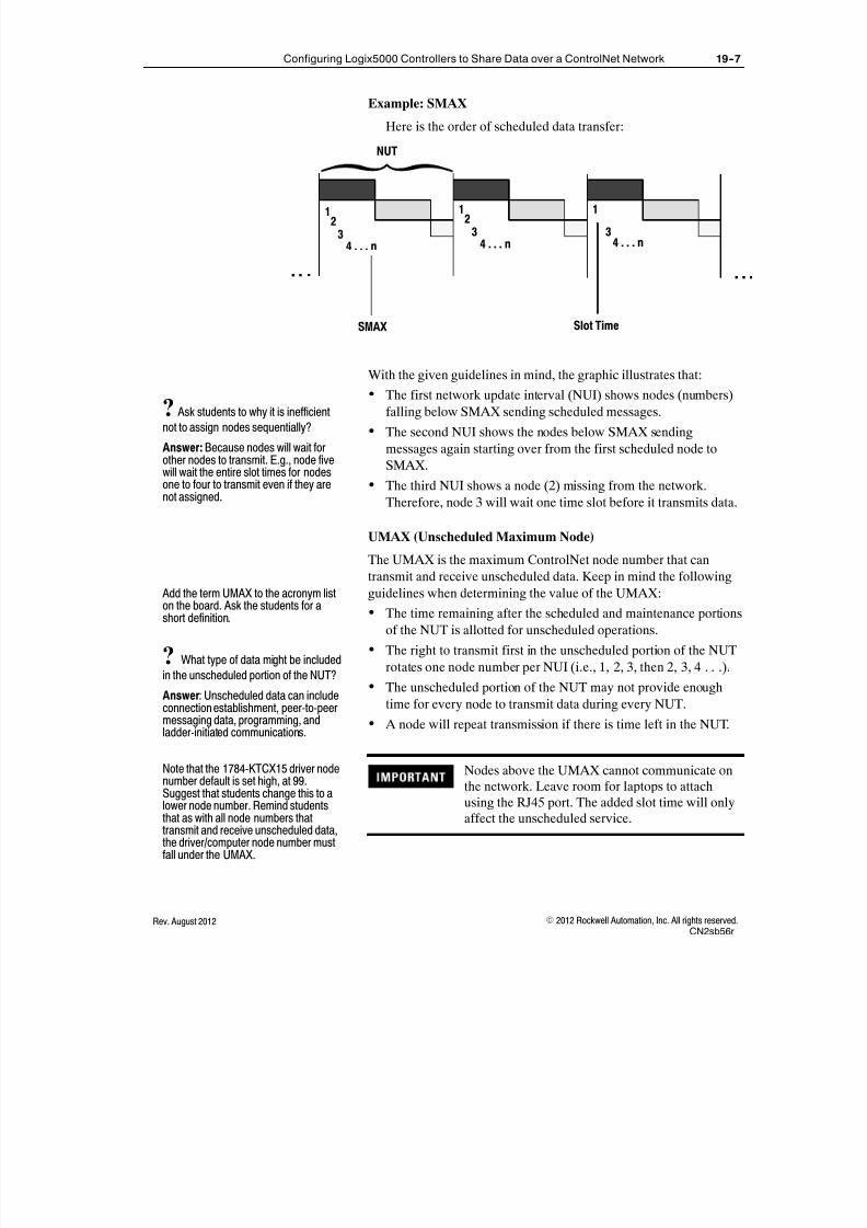
8/16/2019 Student Manual _ ABT-CCP-TSM143 _ RSLogix 5000, Level 3 _ Project Development.pdf
http://slidepdf.com/reader/full/student-manual-abt-ccp-tsm143-rslogix-5000-level-3-project-developmentpdf 339/375
19--7Configuring Logix5000 Controllers to Share Data over a ControlNet Network
E 2012 Rockwell Automation, Inc. All rights reserved.Rev. August 2012CN2sb56r
Example: SMAX
Here is the order of scheduled data transfer:
NUT
. . . . . .
1
Slot TimeSMAX
23
4 . . . n
12
34 . . . n
1
34 . . . n
With the given guidelines in mind, the graphic illustrates that: The first network update interval (NUI) shows nodes (numbers)
falling below SMAX sending scheduled messages.
The second NUI shows the nodes below SMAX sending
messages again starting over from the first scheduled node to
SMAX.
The third NUI shows a node (2) missing from the network.
Therefore, node 3 will wait one time slot before it transmits data.
UMAX (Unscheduled Maximum Node)
The UMAX is the maximum ControlNet node number that cantransmit and receive unscheduled data. Keep in mind the following
guidelines when determining the value of the UMAX:
The time remaining after the scheduled and maintenance portions
of the NUT is allotted for unscheduled operations.
The right to transmit first in the unscheduled portion of the NUT
rotates one node number per NUI (i.e., 1, 2, 3, then 2, 3, 4 . . .).
The unscheduled portion of the NUT may not provide enough
time for every node to transmit data during every NUT.
A node will repeat transmission if there is time left in the NUT.
Nodes above the UMAX cannot communicate onthe network. Leave room for laptops to attachusing the RJ45 port. The added slot time will onlyaffect the unscheduled service.
? Ask students to why it is inefficient
not to assign nodes sequentially?
Answer: Because nodes will wait forother nodes to transmit. E.g., node fivewill wait the entire slot times for nodesone to four to transmit even if they arenot assigned.
Add the term UMAX to the acronym liston the board. Ask the students for ashort definition.
? What type of data might be included
in the unscheduled portion of the NUT?
Answer: Unscheduled data can includeconnection establishment, peer-to-peermessaging data, programming, andladder-initiated communications.
Note that the 1784-KTCX15 driver nodenumber default is set high, at 99.Suggest that students change this to alower node number. Remind studentsthat as with all node numbers thattransmit and receive unscheduled data,the driver/computer node number mustfall under the UMAX.

8/16/2019 Student Manual _ ABT-CCP-TSM143 _ RSLogix 5000, Level 3 _ Project Development.pdf
http://slidepdf.com/reader/full/student-manual-abt-ccp-tsm143-rslogix-5000-level-3-project-developmentpdf 340/375
19--8 Configuring Logix5000 Controllers to Share Data over a ControlNet Network
E 2012 Rockwell Automation, Inc. All rights reserved. Rev. August 2012CN2sb56r
Time-critical data must not be included in theunscheduled portion of the NUT, as it may nothave the opportunity to be sent every NUT.
Example: UMAX
Here is the rotating order of unscheduled data transfer:
NUT
. . . . . .
7
UMAX
89
89
1011
1011
12
12
3
9
With the given guidelines in mind, the graphic illustrates that:
The opportunity to transmit is passed on a rotating basis.
In the third NUI, UMAX is reached. The remaining
unscheduled time is now available to additional nodes on a
sequential basis starting with node 1.
An unscheduled message can transmit only 500bytes per slot time. If the message is more than500 bytes, the data will resume transmission on itsnext turn.
The same node can transmit both scheduled andunscheduled data. For example, the controllermight produce a tag (scheduled) and send amessage (unscheduled).
Media Redundancy
The network must be configured for one of the following media
redundancy options:
A only, for one cable system using channel A
B only, for one cable system using channel B
A and B, for redundant media
? If UMAX was reached in the second
NUI, which node would transmitunscheduled data first in thethird NUI?
Answer: Node 1.
In the graphic, point out thatif time remains after theUMAX is reached, theremaining time starts overwith node one (scheduled
nodes).
Point out in the graphic that node 7transmits first in the first NUI, node 8transmits first in the second NUI, andnode 9 transmits first in the third NUI.
Note that to send data over 500 bytes inchunks, frame numbers are assigned tothe data.
Add that all nodes on a network must bethe same. That is, one node cannot beset for channel A and another node setfor channel B.

8/16/2019 Student Manual _ ABT-CCP-TSM143 _ RSLogix 5000, Level 3 _ Project Development.pdf
http://slidepdf.com/reader/full/student-manual-abt-ccp-tsm143-rslogix-5000-level-3-project-developmentpdf 341/375
19--9Configuring Logix5000 Controllers to Share Data over a ControlNet Network
E 2012 Rockwell Automation, Inc. All rights reserved.Rev. August 2012CN2sb56r
To ensure optimization of data transfer, anaccurate representation of the media used on thenetwork should be defined in RSNetWorx forControlNet software.
Update Intervals
The configured or requested node transmit time may be different
than the actual transmit time, as described in the following intervals:
RPI (Requested Packet Interval)
API (Actual Packet Interval)
RPI (Requested Packet Interval)
The RPI is a user-specified rate that is supplied when an I/O module
or ControlNet module is configured. The RPI defines how long themodule will wait before multicasting its data.
When determining the value of the RPI to enter in the I/O
configuration, note the following:
Each node may have different requirements for sending data
within the NUT.
It is inefficient to send all data at the same rate.
A node can support more than one rate depending on the data
being sent.
RPI must be greater than or equal to the NUT.
API (Actual Packet Interval)
The API is the actual resulting interval. It can be described as
follows:
This rate is based on the NUT and is less than or equal to the RPI.
This rate supports values that are binary multiples (1, 2, 4, 8, 16,
32, 64, 128) of the NUT.
ControlNet networks will always meet or beat the RPI:
-- If the RPI is 20 ms and the nut is 8 ms, the API will be 16 ms
(faster) because it cannot release at 20 ms.
Add the term RPI to the acronym list on
the board. Ask the students for a shortdefinition.
Clarify that the RPI tells the moduleswhen to multicast its data.
Add the term API to the acronym list onthe white board. Ask the students for ashort definition.

8/16/2019 Student Manual _ ABT-CCP-TSM143 _ RSLogix 5000, Level 3 _ Project Development.pdf
http://slidepdf.com/reader/full/student-manual-abt-ccp-tsm143-rslogix-5000-level-3-project-developmentpdf 342/375
19--10 Configuring Logix5000 Controllers to Share Data over a ControlNet Network
E 2012 Rockwell Automation, Inc. All rights reserved. Rev. August 2012CN2sb56r
Example: RPI and API
The requested transmit time versus the actual transmit time is
illustrated in the following graphic:
NUT = 2 ms
RPI for discrete data = 10 ms API for discrete data = 8 ms
Data Data
Interval 1 Interval 2 Interval 3 Interval 4 Interval 5
2 ms 2 ms 2 ms 2 ms 2 ms
The example illustrates the following points:
Discrete data has an RPI of ten milliseconds. The software generates an API of eight milliseconds (eight is
the closest binary multiple that is less than ten).
The data is sent every four NUTs.
Configuration Overview and Software Interfaces
To schedule the ControlNet network in order to share data, it is
necessary to complete the following procedures:
1. Create the required produced tag.
2. In the controller that is consuming the data, perform the followingactions:
A. Add the local ControlNet module to the I/O configuration.
B. Add the remote ControlNet module to the I/O configuration.
C. Add the producing controller to the I/O configuration.
D. Create the required consumed tags.
3. Schedule the ControlNet network.
After reviewing the graphic and thecorresponding statements, ask thestudents to determine the API for thefollowing RPI rates:
1. 100 ms Answer: 64 ms2. 31 ms Answer: 16 ms
3. 2 ms Answer: 2 ms
After reviewing RPI and API, test thestudents’ understanding of the first halfof the lesson, including the following keyconcepts:
S Producer/Consumer model
S NUT, SMAX, UMAX, RPI, and API
Having a good understanding of theparameters of the ControlNet network is
required to begin examining the softwareinterfaces and configuration steps.
Break: Note that the introduction of theControlNet network concepts ends here.This is a good place to take a shortbreak if necessary.
Note that this section is a generalintroduction to the flow of configurationprocedures. The step-by-step detailsand software demonstrations will bepresented in the Here’s How section. If
this lesson is part of a national school,add that remote I/O will be discussed ina different lesson.
Encourage students to ask anyremaining questions from theConfiguring a Logix5000 Controller toProduce and Consume Data lesson.
Note that the connection will be madethrough a ControlNet or Ethernetnetwork.

8/16/2019 Student Manual _ ABT-CCP-TSM143 _ RSLogix 5000, Level 3 _ Project Development.pdf
http://slidepdf.com/reader/full/student-manual-abt-ccp-tsm143-rslogix-5000-level-3-project-developmentpdf 343/375
19--11Configuring Logix5000 Controllers to Share Data over a ControlNet Network
E 2012 Rockwell Automation, Inc. All rights reserved.Rev. August 2012CN2sb56r
Adding a ControlNet Module and Controller to an I/O
Configuration
The following graphic is an example of a remote ControlNet module
and remote controller added to an I/O configuration in
RSLogix 5000 software:
Local ControlNet Module
Remote (Producing) Controller
Remote ControlNet Module
Produced and Consumed Tags
Data that is shared over a ControlNet network must be transferred
using produced tags and received (stored) in consumed tags.
As with I/O modules, when configuring consumed
tags, select an RPI that is greater than the NUT.
Scheduling a New ControlNet Network
RSNetWorx for ControlNet software schedules a network and
connects the local controller to any controllers or I/O modules in a
remote chassis by performing the following actions:
Create a graphical representation of your network configuration
and configure the parameters that define your network.
Analyze all of the intended traffic for the network and then
determine if the requested amount of traffic is possible. Display the current percentage of capacity as well as the
percentage of capacity that added traffic will cause:
-- The user can then decide whether to adjust the requested
traffic or schedule it.
Download to network.
Note that the controller was also addedto the project to share data whenproducing and consuming tags acrossthe backplane. However, the controller isnow added under the remote CNB.
In the graphic, point out that the remotemodule is node 2.
Add that it is not necessary or evenpossible to add the controller running theproject to the configuration.
Note that the produced and consumedtags are created just as they werecreated for transfers over the backplane.

8/16/2019 Student Manual _ ABT-CCP-TSM143 _ RSLogix 5000, Level 3 _ Project Development.pdf
http://slidepdf.com/reader/full/student-manual-abt-ccp-tsm143-rslogix-5000-level-3-project-developmentpdf 344/375
19--12 Configuring Logix5000 Controllers to Share Data over a ControlNet Network
E 2012 Rockwell Automation, Inc. All rights reserved. Rev. August 2012CN2sb56r
To read the connected nodes on the network and build a network
diagram, an online connection must be established using RSNetWorx
for ControlNet software:
NetworkDiagram
Online Option
Online BandwidthPercentages
Enable EditsOption
The online Average Scheduled Bandwidthpercentage should not exceed 50% or 60%.
Point out that the procedure forscheduling a ControlNet network isdetailed in the Procedures Guide. Notethat the steps will be demonstrated inthe Here’s How section.

8/16/2019 Student Manual _ ABT-CCP-TSM143 _ RSLogix 5000, Level 3 _ Project Development.pdf
http://slidepdf.com/reader/full/student-manual-abt-ccp-tsm143-rslogix-5000-level-3-project-developmentpdf 345/375
19--13Configuring Logix5000 Controllers to Share Data over a ControlNet Network
E 2012 Rockwell Automation, Inc. All rights reserved.Rev. August 2012CN2sb56r
After going online, the NUT, SMAX, UMAX, and redundancy
parameters are configured in RSNetWorx for ControlNet software:
Current OnlineValues
PendingChanges
Each time an additional device is added to ascheduled network or an RPI value is changed, theControlNet network must be rescheduled.
A controller must be in Program mode to bescheduled.
RSNetWorx software communicates with the controller through
RSLinx Classic software.
Using the values in the Pending side ofthe graphic, review the following terms:
S NUT -- Data updates every 5 ms.
S SMAX -- Up to 9 controllers or otherscheduled devices.
S UMAX -- Up to 24 programming orother nonscheduled devices.
Note that the ControlNet schedulinginformation is saved in a .xcconfiguration file.
? What other main function
requires RSLinx Classic software?
Answer: Drivers are configured inRSLinx Classic software.
"Tip

8/16/2019 Student Manual _ ABT-CCP-TSM143 _ RSLogix 5000, Level 3 _ Project Development.pdf
http://slidepdf.com/reader/full/student-manual-abt-ccp-tsm143-rslogix-5000-level-3-project-developmentpdf 346/375
19--14 Configuring Logix5000 Controllers to Share Data over a ControlNet Network
E 2012 Rockwell Automation, Inc. All rights reserved. Rev. August 2012CN2sb56r
To configure a local Logix5000 controller to share data with a
remote Logix5000 controller over a ControlNet network by
performing the following tasks:
Add a ControlNet module to an I/O configuration
Add a controller to an I/O configuration
Schedule a new ControlNet network
Activity: As your instructor demonstrates these procedures, follow
along in the associated job aid(s).
- Location of the procedures in the job aid
- Parent--child relationship of the ControlNet and thecontroller that you add to the I/O configuration
- Produced and consumed tags that you create
- Number of scheduled (SMAX) and the number ofunscheduled (UMAX) nodes
- Values of the ControlNet network after it is configured
Pay attention to these critical aspects of the demonstration:
Here’s How
IMPORTANT: To meet IACET CEUrequirements and fully preparecertificate students for the final exam,you must demonstrate all lessonobjectives using the proper job aids.
Be sure to use theCCP143_1756R_DEM6.acd file andCCP143_1756R_DEM7.acd file.
Demonstration Checklist

8/16/2019 Student Manual _ ABT-CCP-TSM143 _ RSLogix 5000, Level 3 _ Project Development.pdf
http://slidepdf.com/reader/full/student-manual-abt-ccp-tsm143-rslogix-5000-level-3-project-developmentpdf 347/375
19--15Exercise: Configuring Logix5000 Controllers to Share Data over a ControlNet Network
E 2012 Rockwell Automation, Inc. All rights reserved.Rev. August 2012CN2e56r
Exercise: Configuring Logix5000Controllers to Share Data over aControlNet Network
In this exercise, you will practice configuring a local Logix5000
controller to share data with a remote Logix5000 controller over a
ControlNett network.
Context:
You have finished programming and testing a complete project for a
production line. To increase productivity, the plant has set up a
second production line. The second production line needs to receive
(consume) the Pressure data from the first assembly line over a
ControlNet network.
ControlNet Network
Production Line 1 Production Line 2
Produced Consumed
When you see underlined text, refer to the related procedure or
information in your job aid.
In this exercise, you will share data with the other workstation on
your ControlNet network. Node 1 will produce data and node 2 will
consume the data.
Directions:
1. Open the CN2_1756r_A1.acd file (the producer controller.)
2. Create a user-defined data type called Station_Data that will
store the following information from the local controller:
Member Data type Description
AI0 REAL Analog Input channel 0
AI1 REAL Analog Input channel 1
DI DINT Digital Inputs
Exercise A

8/16/2019 Student Manual _ ABT-CCP-TSM143 _ RSLogix 5000, Level 3 _ Project Development.pdf
http://slidepdf.com/reader/full/student-manual-abt-ccp-tsm143-rslogix-5000-level-3-project-developmentpdf 348/375
19--16 Exercise: Configuring Logix5000 Controllers to Share Data over a ControlNet Network
E 2012 Rockwell Automation, Inc. All rights reserved. Rev. August 2012CN2e56r
3. Create a controller scoped tag called Local_Station_Data with
the following properties:
Uses the Station_Data data type
Produced for 1 controller
4. Enter ladder logic to copy your analog channel 0 data and channel1 data as well as your discrete input data to the respective
members of the Local_Station_Data tag.
5. Verify the project, correct any errors, and download the project to
your local controller in slot 1.
6. Place the controller in slot 1 in Remote Run mode.
7. Open the CN2_1756r_A2.acd file (the consumer controller.)
This project will be downloaded to the controller in slot 3 of the
remote workstation after you have completed the configuration.
8. Add the following modules to the I/O configuration (review
workstation configuration for appropriate node addresses):
A. Add the local (relative to the project’s controller) ControlNet
module to the I/O configuration.
B. Nested under the local ControlNet module, add the remote
ControlNet module to the I/O configuration.
C. Nested under the remote ControlNet module, add the
controller in slot 1 of the remote workstation to the I/O
configuration and call it Remote_Controller.
9. Copy the Station_Data UDT from producer and paste it to theconsumer.
10. Consume the Local_Station_Data tag from the
Remote_Controller by performing the following actions:
Create a controller scoped tag called Remote_Station_Data
that uses the Station_Data data type.
Configure Remote_Station_Data as a consumed tag with a
rate of 100 ms.
11. Enter ladder logic to copy the Remote_Station_Data tag to your
analog channel 0 and analog channel 1 outputs.
12. Write the logic so that each of the green buttons pushed on your
workstation will light the corresponding light on the remote
workstation.
13. Verify the project, correct any errors, and download the project to
the remote consumer controller in slot 3.
"Tip

8/16/2019 Student Manual _ ABT-CCP-TSM143 _ RSLogix 5000, Level 3 _ Project Development.pdf
http://slidepdf.com/reader/full/student-manual-abt-ccp-tsm143-rslogix-5000-level-3-project-developmentpdf 349/375
19--17Exercise: Configuring Logix5000 Controllers to Share Data over a ControlNet Network
E 2012 Rockwell Automation, Inc. All rights reserved.Rev. August 2012CN2e56r
Do not schedule the ControlNet network untilboth lines have downloaded the ladder logic.
14. When both production lines are ready, take turns scheduling the
ControlNet network.15. To verify that each production line is correctly configured to
share data, complete the following actions:
A. Verify that moving your analog channel 0 to the middle
position moves the analog channel 0 meter on the remote
workstation to its middle position.
B. Verify that moving your analog channel 1 to the middle
position moves the analog channel 1 meter on the remote
workstation to its middle position.
C. Verify that pushing the first four discrete buttons on your
workstation light the corresponding lights on the remote
workstation.
Turn to the Answers section.How Did You Do?

8/16/2019 Student Manual _ ABT-CCP-TSM143 _ RSLogix 5000, Level 3 _ Project Development.pdf
http://slidepdf.com/reader/full/student-manual-abt-ccp-tsm143-rslogix-5000-level-3-project-developmentpdf 350/375
19--18 Exercise: Configuring Logix5000 Controllers to Share Data over a ControlNet Network
E 2012 Rockwell Automation, Inc. All rights reserved. Rev. August 2012CN2e56r
Exercise A
2. The user-defined data type should look similar to the following
example:
3. The tag created should look similar to the following example:
Answers

8/16/2019 Student Manual _ ABT-CCP-TSM143 _ RSLogix 5000, Level 3 _ Project Development.pdf
http://slidepdf.com/reader/full/student-manual-abt-ccp-tsm143-rslogix-5000-level-3-project-developmentpdf 351/375
19--19Exercise: Configuring Logix5000 Controllers to Share Data over a ControlNet Network
E 2012 Rockwell Automation, Inc. All rights reserved.Rev. August 2012CN2e56r
4. Your ladder logic should look similar to the following example:
8. The I/O configuration should look similar to the following
example:
The node addresses ofyour ControlNet
modules will vary basedon your setup
The slot 1 controller
9. The Station_Data UDT should now be found in the
CN2_1756r_A2 project:

8/16/2019 Student Manual _ ABT-CCP-TSM143 _ RSLogix 5000, Level 3 _ Project Development.pdf
http://slidepdf.com/reader/full/student-manual-abt-ccp-tsm143-rslogix-5000-level-3-project-developmentpdf 352/375
19--20 Exercise: Configuring Logix5000 Controllers to Share Data over a ControlNet Network
E 2012 Rockwell Automation, Inc. All rights reserved. Rev. August 2012CN2e56r
10. The consumed tag should look similar to the following
example:
11. Your ladder logic should look similar to the following example:

8/16/2019 Student Manual _ ABT-CCP-TSM143 _ RSLogix 5000, Level 3 _ Project Development.pdf
http://slidepdf.com/reader/full/student-manual-abt-ccp-tsm143-rslogix-5000-level-3-project-developmentpdf 353/375
19--21Exercise: Configuring Logix5000 Controllers to Share Data over a ControlNet Network
E 2012 Rockwell Automation, Inc. All rights reserved.Rev. August 2012CN2e56r
12. Your ladder logic should look similar to the following example:

8/16/2019 Student Manual _ ABT-CCP-TSM143 _ RSLogix 5000, Level 3 _ Project Development.pdf
http://slidepdf.com/reader/full/student-manual-abt-ccp-tsm143-rslogix-5000-level-3-project-developmentpdf 354/375
19--22 Exercise: Configuring Logix5000 Controllers to Share Data over a ControlNet Network
E 2012 Rockwell Automation, Inc. All rights reserved. Rev. August 2012CN2e56r

8/16/2019 Student Manual _ ABT-CCP-TSM143 _ RSLogix 5000, Level 3 _ Project Development.pdf
http://slidepdf.com/reader/full/student-manual-abt-ccp-tsm143-rslogix-5000-level-3-project-developmentpdf 355/375
Optional Lesson 20
E 2012 Rockwell Automation, Inc. All rights reserved.Rev. August 2012RC2sb56r
Communicating with a 1756-I/OModule Over a ControlNet Network
After completing this lesson, you should be able to:
Add a remote 1756-I/O module to an I/O configuration
Reschedule an existing ControlNett network
When You Will Do This
RSLogix 5000 software lets you add your I/O configuration to the
project before, during, or after you develop your application logic.
Do this task when:
Your I/O modules are connected to the controller by a ControlNet
network, and
Your system is installed or you have drawings and specifications
that outline to location and configuration of your I/O modules
ControlNet Remote I/O
Configuring remote I/O using a ControlNet network requires the
following tasks to be performed:
1. Add the local and remote ControlNet module to an I/O
configuration.
2. Add a remote 1756-I/O module to an I/O configuration.
3. Schedule the ControlNet network.
Here is a summary of when the data updates:
For this remote module If data is multicast in the same
chassis If data Is transferred across a ControlNet network
Digital Input
RPI and COS values define when the
module multicasts data within its own
chassis.
The RPI only determines when the owner controller receives the data
over the network.
" The timing may not coincide with the exact value of the RPI;however, the owner-controller will receive data at least as often as
the RPI.
Digital Output N/A An output receives data from the owner-controller only at the RPI rate.
Analog Input
The RPI and RTS rates define when the
module multicasts data within its own
chassis.
The RPI only determines when the owner- controller receives the data
over the network.
Analog Output N/A An output receives data from the owner-controller only at the RPI rate.
What You Will LearnNote that in the prerequisite ControlNetlesson , students learned to schedule aControlNet network. In this lesson,students will practice rescheduling anexisting network, a common andimportant task.
Before You Begin
In the standard school, note that theControlNet network was previouslyscheduled. This lesson will provide anopportunity to reschedule the network --a common and important action.

8/16/2019 Student Manual _ ABT-CCP-TSM143 _ RSLogix 5000, Level 3 _ Project Development.pdf
http://slidepdf.com/reader/full/student-manual-abt-ccp-tsm143-rslogix-5000-level-3-project-developmentpdf 356/375
20--2 Communicating with a 1756-I/O Module Over a ControlNet Network
E 2012 Rockwell Automation, Inc. All rights reserved. Rev. August 2012RC2sb56r
To perform the following tasks:
Add a remote 1756-I/O module to an I/O configuration
Reschedule an existing ControlNet network
Activity: As your instructor demonstrates these procedures, follow
along in the associated job aid(s).
- Location of the procedures in the job aid
- Parent-child relationship with the ControlNet module andthe remote modules
- Module configuration, including the multicasting rates
- Resulting module tags
Pay attention to these critical aspects of the demonstration:
Here’s How
IMPORTANT: To meet IACET CEUrequirements and fully preparecertificate students for the final exam,you must demonstrate all lessonobjectives using the proper job aids.
Continue with the RSLogix 5000 projectyou used for sharing data over aControlNet network.
Note that if you saved the demonstrationfile from the Configuring Logix5000Controllers to Share Data over aControlNet Network lesson, it is notrequired to configure the remote I/Omodule.
Demonstration Checklist

8/16/2019 Student Manual _ ABT-CCP-TSM143 _ RSLogix 5000, Level 3 _ Project Development.pdf
http://slidepdf.com/reader/full/student-manual-abt-ccp-tsm143-rslogix-5000-level-3-project-developmentpdf 357/375
20--3Exercise: Communicating with a 1756-I/O Module Over a ControlNet Network
E 2012 Rockwell Automation, Inc. All rights reserved.Rev. August 2012RC2e56r
Exercise: Communicating with a1756-I/O Module Over a ControlNetNetwork
In this exercise, you will practice configuring a Logix5000 controller
to communicate with a 1756-remote I/O module and reschedule the
ControlNet network.
Context:
You have programmed a complete project. As a safety feature for
plant personnel, you want to program an output light to be on when
the production line is active. Because you have used your available
I/O points in the local chassis, you must add a remote chassis to
accommodate the additional I/O requirements. You are now ready to
configure the controller to communicate with the 1756-remote I/O
module.
The setup of the remote output is shown in the following graphic:
ControlNet NetworkLocal
ChassisRemoteChassis
ProductionLine ActiveProduction Line
In this exercise, you will share data with another workstation on a
ControlNet network. Your workstation will be the local chassis. The
other workstation will be the remote chassis.
When you see underlined text, refer to the related procedure or
information in your job aid.
Directions:
1. Download the Blank.acd file to the controller in slot 3.
2. Open the RC2_1756r_A1.acd file.
3. Add the local and remote ControlNet modules to the project I/O
configuration.
4. Add and configure the remote output module in slot 4. You will
be owning this module, which is located in the remote chassis.
Exercise A
"Tip

8/16/2019 Student Manual _ ABT-CCP-TSM143 _ RSLogix 5000, Level 3 _ Project Development.pdf
http://slidepdf.com/reader/full/student-manual-abt-ccp-tsm143-rslogix-5000-level-3-project-developmentpdf 358/375
20--4 Exercise: Communicating with a 1756-I/O Module Over a ControlNet Network
E 2012 Rockwell Automation, Inc. All rights reserved. Rev. August 2012RC2e56r
5. Add the local input module that is in slot 2 to your I/O
configuration. You will also be owning this module.
6. Make a new tag, DI12, an alias tag for bit 12 of the local digital
input card in slot 2.
7. Make a new tag, DO11, an an alias tag for bit 11 of the remotedigital output card in slot 4.
8. Enter the following ladder logic in your MainRoutine:
9. Download the project to the controller in slot 1 of the
local chassis.
Do not reschedule the ControlNet network untilthe projects have been downloaded to both thelocal and remote controllers.
10. When both lines are ready, reschedule the ControlNet network.
11. Test the project and verify that you have correctly configured the
remote I/O by performing the following actions:
A. Start the conveyor by energizing DI12.
B. Verify that the remote I/O light DO11 on the other
workstation is on.
C. Turn off DI12 and verify that the remote I/O light on the
other workstation is off.
D. When the project functions correctly, go offline.
Turn to the Answers section.How Did You Do?

8/16/2019 Student Manual _ ABT-CCP-TSM143 _ RSLogix 5000, Level 3 _ Project Development.pdf
http://slidepdf.com/reader/full/student-manual-abt-ccp-tsm143-rslogix-5000-level-3-project-developmentpdf 359/375
20--5Exercise: Communicating with a 1756-I/O Module Over a ControlNet Network
E 2012 Rockwell Automation, Inc. All rights reserved.Rev. August 2012RC2e56r

8/16/2019 Student Manual _ ABT-CCP-TSM143 _ RSLogix 5000, Level 3 _ Project Development.pdf
http://slidepdf.com/reader/full/student-manual-abt-ccp-tsm143-rslogix-5000-level-3-project-developmentpdf 360/375
20--6 Exercise: Communicating with a 1756-I/O Module Over a ControlNet Network
E 2012 Rockwell Automation, Inc. All rights reserved. Rev. August 2012RC2e56r
Exercise A
3. Your main configuration screen for the local ControlNet module
in slot 5 should look similar to the example (The ControlNet
node number will vary depending on your workstation setup.):
The remote ControlNet module is added to the I/O
Configuration by right-clicking the ControlNet network icon
displayed below the local ControlNet module:
Answers

8/16/2019 Student Manual _ ABT-CCP-TSM143 _ RSLogix 5000, Level 3 _ Project Development.pdf
http://slidepdf.com/reader/full/student-manual-abt-ccp-tsm143-rslogix-5000-level-3-project-developmentpdf 361/375
20--7Exercise: Communicating with a 1756-I/O Module Over a ControlNet Network
E 2012 Rockwell Automation, Inc. All rights reserved.Rev. August 2012RC2e56r
Your main configuration screen for the remote ControlNet
module in slot 5 should look similar to the example (The
ControlNet node address will vary depending on your
workstation setup.):
4. Add the remote output module by right-clicking the backplane
displayed beneath the remote ControlNet module:

8/16/2019 Student Manual _ ABT-CCP-TSM143 _ RSLogix 5000, Level 3 _ Project Development.pdf
http://slidepdf.com/reader/full/student-manual-abt-ccp-tsm143-rslogix-5000-level-3-project-developmentpdf 362/375
20--8 Exercise: Communicating with a 1756-I/O Module Over a ControlNet Network
E 2012 Rockwell Automation, Inc. All rights reserved. Rev. August 2012RC2e56r
Your main configuration screen for the remote output module in
slot 4 should look similar to the example:
5. Your main configuration screen for the local input module inslot 2 should look similar to the example:
(Continued)
Your completed I/O Configuration within the Controller
Organizer should look similar to the following:

8/16/2019 Student Manual _ ABT-CCP-TSM143 _ RSLogix 5000, Level 3 _ Project Development.pdf
http://slidepdf.com/reader/full/student-manual-abt-ccp-tsm143-rslogix-5000-level-3-project-developmentpdf 363/375
20--9Exercise: Communicating with a 1756-I/O Module Over a ControlNet Network
E 2012 Rockwell Automation, Inc. All rights reserved.Rev. August 2012RC2e56r
10. If you did not receive the appropriate system response after
rescheduling the ControlNet network, verify that you have
completed the following actions:
- Set the SMAX to be equal to the highest number node thatcan use scheduled time on the network
- Set the UMAX to be equal to the highest number node thatcan use unscheduled time on the network
- Reschedule the network if any changes were made after thefirst rescheduling

8/16/2019 Student Manual _ ABT-CCP-TSM143 _ RSLogix 5000, Level 3 _ Project Development.pdf
http://slidepdf.com/reader/full/student-manual-abt-ccp-tsm143-rslogix-5000-level-3-project-developmentpdf 364/375
20--10 Exercise: Communicating with a 1756-I/O Module Over a ControlNet Network
E 2012 Rockwell Automation, Inc. All rights reserved. Rev. August 2012RC2e56r

8/16/2019 Student Manual _ ABT-CCP-TSM143 _ RSLogix 5000, Level 3 _ Project Development.pdf
http://slidepdf.com/reader/full/student-manual-abt-ccp-tsm143-rslogix-5000-level-3-project-developmentpdf 365/375
Appendix A
E 2012 Rockwell Automation, Inc. All rights reserved.Rev. August 2012WDAa56r
I/O Wiring Diagrams For TheAssembly Application
Slot 0 - 1756-OB16D Digital Output Module
WORKSTATIONDEVICE LABEL
- GREEN PILOT LIGHTG
A
R
- AMBER PILOT LIGHT
- RED PILOT LIGHT
1 DO0GOUT-02
4
6
8
10
12
14
16
18
20
22
24
26
28
30
32
34
36
+DC-0
+DC-0
+DC-0
+DC-0+DC-0
+DC-0
+DC-0
GND-0
+DC-1
+DC-1
+DC-1
+DC-1
+DC-1
+DC-1
+DC-1GND-1
GND-1
Not Used
B L A C K
B L A C K
RED
RED
24VDC
3
9
OUT-1
OUT-4
G
R
DO1
DO4
7 OUT-3
A
DO3
11 OUT-5 DO5
OUT-2 DO2
5 R
A
APPLICATIONOUTPUT
CONVEYOR
STATION OUTPUT (WELD)
STATION OUTPUT (STAKE)
STATION OUTPUT (PRESS)

8/16/2019 Student Manual _ ABT-CCP-TSM143 _ RSLogix 5000, Level 3 _ Project Development.pdf
http://slidepdf.com/reader/full/student-manual-abt-ccp-tsm143-rslogix-5000-level-3-project-developmentpdf 366/375
A--2 I/O Wiring Diagrams For The Assembly Application
E 2012 Rockwell Automation, Inc. All rights reserved. Rev. August 2012WDAa56r
Slot 2 - 1756-IB16D Digital Input Module
- SELECTOR SWITCH
DI4
DI5
1
9
11
DI0IN-0
IN-4
2
4
6
8
10
12
14
16
18
20
22
24
26
28
30
32
34
36
GND-0
GND-0
GND-0
GND-0
GND-1
GND-1
GND-1
GND-1
GND-2
GND-2
GND-2
GND-2
GND-3
GND-3
GND-3
GND-3
GND-3
NOT USED
B L A C K
BLACK
- NORMALLY OPEN PUSHBUTTON
BLACK
BLACK
15
13
21
23
17
19
27
25
33
35
29
31
NOT USED
NOT USED
IN-5
IN-6
IN-7
IN-8
IN-9
IN-10
IN-11
IN-12
IN-15
DI7
DI9
DI10DI11
DI6
DI8
DI15
DI12
LABELWORKSTATION
DEVICE
3 DI1
IN-1
5 DI2
IN-2
7 DI3
IN-3
IN-14 DI14
IN-13 DI13
+24VDCAPPLICATIONOUTPUT
START
PART SENSOR
STOP
READ REMOTE TOTAL
PART SENSOR FAULT RESET

8/16/2019 Student Manual _ ABT-CCP-TSM143 _ RSLogix 5000, Level 3 _ Project Development.pdf
http://slidepdf.com/reader/full/student-manual-abt-ccp-tsm143-rslogix-5000-level-3-project-developmentpdf 367/375
A--3I/O Wiring Diagrams For The Assembly Application
E 2012 Rockwell Automation, Inc. All rights reserved.Rev. August 2012WDAa56r
Slot 4 - 1756-OB16D Digital Output Module
DO7
DO9
DO10
DO11
- GREEN PILOT LIGHTG
A
R
- AMBER PILOT LIGHT
- RED PILOT LIGHT
G
A
R
13
19
21
15
17
DO6
DO8
G
A
R
OUT-6
OUT-7
OUT-8
OUT-9
OUT-10
OUT-11
2
4
6
8
10
12
14
16
18
20
22
24
26
28
30
32
34
36
+DC-0
+DC-0+DC-0
+DC-0
+DC-0
+DC-0
+DC-0
GND-0
+DC-1
+DC-1
+DC-1
+DC-1
+DC-1
+DC-1
+DC-1
GND-1
GND-1
NOT USED
B L A C K
B
L A C K
RED
RED
+24VDC
23
LABELWORKSTATIONDEVICE
APPLICATIONOUTPUT
PART SENSOR FAULT INDICATOR
STATION OUTPUT (REJECT)
STATION OUTPUT (PALLETIZE)
LINE ACTIVE

8/16/2019 Student Manual _ ABT-CCP-TSM143 _ RSLogix 5000, Level 3 _ Project Development.pdf
http://slidepdf.com/reader/full/student-manual-abt-ccp-tsm143-rslogix-5000-level-3-project-developmentpdf 368/375
A--4 I/O Wiring Diagrams For The Assembly Application
E 2012 Rockwell Automation, Inc. All rights reserved. Rev. August 2012WDAa56r
Slot 7 - 1756-OF6VI Analog Output Module
NOT USED3
1
9
11
5
7
2
4
6
8
10
12
14
16
18
20
15
13
17
19
OUT-0
RTN-0
OUT-2
NOT USED
RTN-2
OUT-4
RTN-4
NOT USED
NOT USED
NOT USED
OUT-1
RTN-1
OUT-3
NOT USED
RTN-3
OUT-5
RTN-5
NOT USED
NOT USED
WORKSTATIONDEVICE
AO1 (Channel 1)
WORKSTATIONDEVICE
AO0Return
AO1Return
AO0 (Channel 0)

8/16/2019 Student Manual _ ABT-CCP-TSM143 _ RSLogix 5000, Level 3 _ Project Development.pdf
http://slidepdf.com/reader/full/student-manual-abt-ccp-tsm143-rslogix-5000-level-3-project-developmentpdf 369/375
A--5I/O Wiring Diagrams For The Assembly Application
E 2012 Rockwell Automation, Inc. All rights reserved.Rev. August 2012WDAa56r
Slot 8 - 1756-IF6I Analog Input Module
IN-0/I
AI0(Channel 0)
3
1
9
11
5
7
2
4
6
8
10
12
14
16
18
20
15
13
17
19
IN-0/V
RET-0
IN-2/V
IN-2/I
RET-2
IN-4/V
RET-4
NOT USED
IN-4/I
IN-1/I
IN-1/V
RET-1
IN-3/V
IN-3/I
RET-3
IN-5/V
RET-5
NOT USED
IN-5/I
WORKSTATION
DEVICE
AI1Return
AI1(Channel 1)
AI0Return
WORKSTATION
DEVICE
+10VDC+10VDC

8/16/2019 Student Manual _ ABT-CCP-TSM143 _ RSLogix 5000, Level 3 _ Project Development.pdf
http://slidepdf.com/reader/full/student-manual-abt-ccp-tsm143-rslogix-5000-level-3-project-developmentpdf 370/375
A--6 I/O Wiring Diagrams For The Assembly Application
E 2012 Rockwell Automation, Inc. All rights reserved. Rev. August 2012WDAa56r

8/16/2019 Student Manual _ ABT-CCP-TSM143 _ RSLogix 5000, Level 3 _ Project Development.pdf
http://slidepdf.com/reader/full/student-manual-abt-ccp-tsm143-rslogix-5000-level-3-project-developmentpdf 371/375
Appendix B
E 2012 Rockwell Automation, Inc. All rights reserved.Rev. August 2012WI3a56r
ControlLogix Workstation I/ODevice Assignments
The following standard ControlLogix workstation inputs and outputs
are used in this course (Local I/O tags are listed on the next page):
D I 0
D I 1
D I 3
D I 4
D I 1 1
D I 1 3
D I 7
D I 6
D I 1 0
D I 1 2
D I 5
D I 9
D I 8
D I 1 4
D I 1 5
D O 0
D O 1
D O 2
D O 3
D O 4
D O 5
D O 7
D O 8
D O 9
D O 1 0
D O 1 1
I n p u t s R u n L e f t t o R i g h t ( A l l W i r e d t o S
l o t 2 )
O u t p u t s ( 0 -
5 i n S l o t 0 )
D I 2
D O 6
C h 0 0 A n a l o g
M e t e r I n p u t
C h 0 1 A n a l o g
M e t e r I n p u t
C h 0 0 A n
a l o g
M e t e r O u
t p u t
C h 0 1 A
n a l o g
M e t e r O
u t p u t
O u t p u t s ( 6 -
1 1 i n S
l o t 4 )

8/16/2019 Student Manual _ ABT-CCP-TSM143 _ RSLogix 5000, Level 3 _ Project Development.pdf
http://slidepdf.com/reader/full/student-manual-abt-ccp-tsm143-rslogix-5000-level-3-project-developmentpdf 372/375
B--2 ControlLogix Workstation I/O Device Assignments
E 2012 Rockwell Automation, Inc. All rights reserved. Rev. August 2012WI3a56r
The devices used in the workstation have the following I/O base
tags:
Module Workstation Device I/O Base Tag
Digital Inputwired to Slot 2
DI0 Local:2:I.Data.0
DI1 Local:2:I.Data.1DI2 Local:2:I.Data.2
DI3 Local:2:I.Data.3
DI4 Local:2:I.Data.4
DI5 Local:2:I.Data.5
DI6 Local:2:I.Data.6
DI7 Local:2:I.Data.7
DI8 Local:2:I.Data.8
DI9 Local:2:I.Data.9
DI10 Local:2:I.Data.10
DI11 Local:2:I.Data.11
DI12 Local:2:I.Data.12
DI13 Local:2:I.Data.13
DI14 Local:2:I.Data.14
DI15 Local:2:I.Data.15
Digital Outputwired to Slot 0
D00 Local:0.O.Data.0
D01 Local:0.O.Data.1
D02 Local:0.O.Data.2
D03 Local:0.O.Data.3
D04 Local:0.O.Data.4
D05 Local:0.O.Data.5
Digital Outputwired to Slot 4
D06 Local:4:O.Data.6
D07 Local:4:O.Data.7
D08 Local:4:O.Data.8
D09 Local:4:O.Data.9
D010 Local:4:O.Data.10
D011 Local:4:O.Data.11
Local I/O Tags

8/16/2019 Student Manual _ ABT-CCP-TSM143 _ RSLogix 5000, Level 3 _ Project Development.pdf
http://slidepdf.com/reader/full/student-manual-abt-ccp-tsm143-rslogix-5000-level-3-project-developmentpdf 373/375
Appendix C
E 2012 Rockwell Automation, Inc. All rights reserved.Rev. August 2012NO3a56r
Node Assignments
If you are in an environment with multiple workstations on a
ControlNet or EtherNet/IP network, ask your network specialist to
supply the following information:
Workstation
Number
EtherNet or EtherNet/IP
Network ControlNet Network
1756-ENBT IP Address
1756-CNB
or
1756-CN2
Node
Address*
1784-PCICS
Card Node
Address
1784-PCC
Card Node
Address
1784-KTCX15 Interface
Card
1
2
3
4
5
6
7
8
9
10

8/16/2019 Student Manual _ ABT-CCP-TSM143 _ RSLogix 5000, Level 3 _ Project Development.pdf
http://slidepdf.com/reader/full/student-manual-abt-ccp-tsm143-rslogix-5000-level-3-project-developmentpdf 374/375
C--2 Node Assignments
E 2012 Rockwell Automation, Inc. All rights reserved. Rev. August 2012NO3a56r

8/16/2019 Student Manual _ ABT-CCP-TSM143 _ RSLogix 5000, Level 3 _ Project Development.pdf
http://slidepdf.com/reader/full/student-manual-abt-ccp-tsm143-rslogix-5000-level-3-project-developmentpdf 375/375
The following are trademarks of Rockwell Automation, Inc.:
1336 FORCE 1336 IMPACT
1336 PLUS CompactLogix
ControlBus ControlLogix
Data Highway Plus DH+
DriveTools FactoryTalk
Flex FlexLogix
Logix5000 Logix5550
PanelBuilder PanelView
PLC-5 PHOTOSWITCH
PowerFlex RediSTATION
RSLinx RSLogix
RSView RSNetWorx
SCANPort SLC
SoftLogix Ultra
EtherNet/IP and ControlNet are trademarks of ControlNet International Ltd.
DeviceNet is a trademark of the Open DeviceNet Vendor Association, Inc. (ODVA).
The following are registered trademarks of Microsoft Corporation:
MS-DOS PowerPoint
Windows Windows NT
IBM is a registered trademark of International Business Machines Corporation.
Pentium is a registered trademark of Intel Corporation.
All other trademarks are the property of their respective holders and are hereby acknowledged.