Embed Size (px)
Citation preview

STREET DESIGN AND ACCESS CONTROL
Technical Design Manual #4
January 2014


City of Chandler Street Design and Access Control January 2014 TDM #4
TECHNICAL DESIGN MANUAL NUMBER 4
CHANDLER POLICIES AND GUIDELINES FOR
STREET DESIGN AND ACCESS CONTROL
TABLE OF CONTENTS
Page
I. Policy 1
II. Definitions 2
III. Design Standards 4
3.1 General Considerations 4
3.2 Standard Specifications and Details 4
3.3 Horizontal Alignment 5
3.4 Vertical Alignment 9
3.5 Raised Barrier Median Design 9
3.6 Miscellaneous Geometric Standard 9
3.7 Deceleration Lanes and Bus Bays Design 14
3.8 Bus Bays or Pullouts, Bus Stops and Bus Shelter 17
3.9 Drainage Structures 18
3.10 Arterial Street Lane Widths 19
3.11 Cluster Development with Private Shared Driveway 19
IV. Pavement Structural Design Standards 22
4.1 Flexible Pavement 22
4.2 Rigid Pavement 22
4.3 Decorative Pavement 22
4.4 Miscellaneous Pavement Standards 22
V. Miscellaneous Street Standards 23
5.1 Traffic Control Devices and Street Name Signs 23
5.2 Partial Street and Half-Street Standards 25
5.3 Phasing Requirements 26
5.4 Private Streets and Private Shared Driveways 26
5.5 Streetlights 26
5.6 Traffic Calming Devices 27
VI. Plan Requirements 28
VII. Access Control Policies and Guidelines 29
7.1 General Considerations 29
7.2 Definitions 30
7.3 Access Locations Along Arterial Streets 30
7.4 Planning and Design for Intersections 32
7.5 Access Driveway Location 33
7.6 Access Driveway Design 34

City of Chandler Street Design and Access Control January 2014 TDM #4
LIST OF TABLES
Page
Table 1 - Subgrade Compaction Requirements for Curbs,
Gutters, and Sidewalks 5
Table 2 - Summary of Design Standards 6
Table 3 - Horizontal Alignment Taper Requirements 7
Table 4 - Minimum Curb Return Radii Requirements 10
Table 5 - Minimum Width Requirements for Private Streets 26
Table 6 - Minimum Stopping Sight Distances 33
Table 7 - Recommended Driveway Dimensions Along Arterial
and Collector Streets 35
LIST OF FIGURES
Page
Figure 1 - Bubbles for Streets 8
Figure 2 - Design Aid for Major Intersection Cross-section 11
Figure 3 - Median Bullnose Location at Intersection 12
Figure 4 - Median Bullnose at Driveway Entrance 13
Figure 5 - Area Triangle 15
Figure 6 - Minimum Turning Radii 16
Figure 11 - Railroad Markings 24
Figure 12 - Driveway Spacing Along Arterial and
Collector Streets 37
Figure 13 - Cluster Configuration Options 21

City of Chandler 1 Street Design and Access Control January 2014 TDM #4
SECTION I
I. POLICY
All streets within, and adjacent to developments shall be improved to City Standards. The
developer is responsible for all costs associated with the required improvements.
Functional classifications for principal arterials and major or minor arterial streets are contained
in the City’s currently effective Transportation Plan. Functional classifications for other streets
shall be determined by the Transportation and Development Director or his designee. Minimum
required rights-of-way widths shall be in accordance with the City Code.
A traffic analysis by a traffic consultant is required for proposed developments determined by the
Transportation and Development Director or his designee to have a large impact on the street
system. The required elements of the traffic analysis are contained in the Policy on Traffic
Impact Assessments for Project Development (Section 7.1.2). The developer is responsible for
the costs of the analysis as well as the costs for implementing the recommendations of the
analysis.

City of Chandler 2 Street Design and Access Control January 2014 TDM #4
SECTION II
II. DEFINITIONS
For the purposes of this manual, the following definitions are used:
Alley: A public thoroughfare that affords only a secondary means of access to abutting property.
(a) Major alley: Serves multifamily residential, commercial, and industrial areas.
(b) Minor alley: Serves single-family residential areas.
Developer: The individual, firm, corporation, partnership, association, syndicate, trust, or other
legal entity that files the application and initiates proceedings for the development and/or
subdivision of land in accordance with the City Code and said developer need not be the owner
of record of said land.
Easement: A grant by the owner for the use of specified land by the public, a corporation, or
persons, for specific uses and purposes and so designated and recorded in the county recorder's
office.
Median: A raised or flush area designed to separate and control vehicular movement.
Pedestrian Way: A public walk dedicated entirely through a block from street to street and/or
providing access to a school, park, recreation area or shopping center.
Right-of-Way: Any land which by deed, conveyance, agreement, easement, dedication, usage,
zoning condition, process of law or other means is reserved for or dedicated to the general public
for street, highway, alley, public utility, or pedestrian walkway purposes and accepted by the
City.
Street: Any existing or proposed street, avenue, boulevard, road, bridge, viaduct, or easement for
public vehicular access or a street shown in a plat duly filed and recorded in the county recorder's
office. A street includes all land within the street right-of-way whether improved or unimproved
and includes such improvements as pavement, shoulders, curbs, gutters, sidewalks, parking
spaces, bridges, viaducts and traffic-control devices.
1) Agrarian street: A street typically located within an agricultural, AG-1 zoning, or
large lot residential district.
2) Arterial street: A major street of exceptional continuity that is intended to carry
the greater portion of through traffic from one area of the City to another and is
generally positioned at one mile intervals. Major and minor arterials are
designated in the current City Transportation Plan.
3) Collector street: A street designed with the primary purpose of collecting and
distributing traffic, to and from, arterial streets.

City of Chandler 3 Street Design and Access Control January 2014 TDM #4
a) Industrial collector: A collector street serving commercial, industrial or other
land uses expected to generate high traffic volumes or substantial heavy truck
traffic.
b) Residential collector: A collector street serving predominantly residential land
uses.
4) Local street: Typically, a street of limited continuity with the primary purpose of
serving only those lots, which are adjacent.
5) Cul-de-sac: A short local street having but one end open for vehicular traffic, the
opposite end being terminated with a permanent turnaround.
6) Private street: A street not owned or maintained by the City.
7) Public street: A street owned and maintained by the City.
8) Driveways:
a) Commercial driveway: Access for retail, office, high density residential or
government/community service building.
b) Industrial driveway: Access for large industrial, office park, mixed use, or
warehouse developments which may also accommodate heavy truck
movements.
c) Residential driveway: Access to single family residence from local or
collector street only. Access from an arterial street is not allowed in the
city.
d) Private shared driveway: driveway serving more than one lot.
e) Parking lot access way: Access to and circulation among parking areas
within an integral apartment or townhouse complex.

City of Chandler 4 Street Design and Access Control January 2014 TDM #4
SECTION III
III. DESIGN STANDARDS
3.1 General Considerations
The design standards presented within this manual should be treated as minimum standards. The
American Association of State Highway and Transportation Officials (AASHTO) has published
several design standard policies. Should a conflict between this manual and an AASHTO policy
occur, the City’s standards or policies shall apply.
All traffic control signs and pavement markings shall be in accordance with the Manual on
Uniform Traffic Control Devices (MUTCD) prepared by the U.S. Department of Transportation
and the City of Chandler's Standard Details. All traffic control materials used shall conform to
Arizona Department of Transportation Standard Drawings and Specifications (ADOT) unless
otherwise noted.
The City Engineer may promulgate additions or revisions to the standards as needs arise.
3.2 Standard Specifications and Details
The City has adopted Maricopa Association of Governments (MAG) Standard Specifications and
Standard Details. Several of those have been modified, as shown in the City’s Standard Details
and Specifications. MAG specifications and details shall be used except where corresponding
specifications or details have been adopted by the City.
Sub-grade relative compaction requirements for curbs, gutters and sidewalks are presented in
Table 1. These shall be used in place of Section 301.3 of the MAG Standard Specifications.

City of Chandler 5 Street Design and Access Control January 2014 TDM #4
TABLE 1
SUBGRADE COMPACTION REQUIREMENTS FOR CURBS, GUTTERS,
AND SIDEWALKS
SWELL, % COMPACTION, %
0 to 1.5 Minimum of 85
Greater than 1.5 Minimum of 80, Maximum of 90
Note: The swell percentage is determined by placing a sample compacted,
remolded, at 2 to 3 percent below the optimum moisture content, Standard Proctor
Test, in a consolodometer apparatus and applying a 100 psf surcharge. The
sample is then saturated and swell values are determined.
Right-of-way width and required improvements for each street classification are found in the City
Standard Details. Newly constructed and reconstructed arterial streets are to be designed to
accommodate on-street bike lanes, except where the necessary street width is not feasible
because of right-of-way or existing development constraints. Bike lanes are to be marked on
collector streets selected by City staff in consultation with the developer or neighborhood
representatives.
A brief summary of the City's design standards is shown in Table 2. Each of the design
standards is discussed in greater detail in the following sections.
3.3 Horizontal Alignment
The minimum horizontal centerline radii shown in Table 2 are for normally crowned streets. The
use of super-elevation to reduce the minimum horizontal centerline radii is prohibited on all
streets except arterials. Super-elevation may be used on arterial streets upon approval of the
Transportation and Development Director or his designee, providing the street cross-slope does
not exceed 4.0%. The City reserves the right to modify the design speeds shown in Table 2 for
arterial and collector streets when justified by special circumstances where overall safety is not
compromised.
For special cases where the minimum tangent lengths shown in Table 2 cannot be achieved, the
Transportation and Development Director or his designee may approve reduced requirements
providing that sight distance and overall safety are not compromised. In general, intersection
tangents will not be required where the radii for both streets are 400 feet or greater.
All street intersections with arterials or major collectors shall be at 90 degrees. All other street
intersections shall not vary from 90 degrees by more than ±15 degrees.
Horizontal curves are not required when the necessary alignment change can be accomplished
with a taper. Taper requirements are given in Table 3. Please note that these taper requirements
also apply when narrowing the improved street width, and may apply to widened sections if
traffic lanes are being offset.

City of Chandler 6 Street Design and Access Control January 2014 TDM #4
TABLE 2
SUMMARY OF DESIGN STANDARDS
STREET TYPE
ITEM
MAJOR &
MINOR
ARTERIAL
COLLECTOR
LOCAL
Design Speed (mph) 55 40 25
Minimum Horizontal
Centerline Radius (ft)
1,800
700 (with
driveways)
400 minimum
(no driveways)
250 (with
driveways)
150 minimum
(no driveways)
Minimum Tangent Length
at Intersections (ft)
(Measured from the intersection center line )*
550
300
150
Cross-Slope (%) 2.5-3.0 2.0-3.0 2.0-3.0
Maximum Longitudinal Slope
Change Not Requiring a
Vertical Curve (%)
1.0
2.0
2.0
Stopping Sight Distance (ft)
Height of eye 3.5 ft., and
Object height 6 in.
550
325
150
Minimum Vertical Curve
Length, Crest (ft)
A=Algebraic Difference in Grades (%)
220 x A
80 x A
20 x A
Minimum Vertical Curve
Length, Sag (ft)
A=Algebraic Difference in Grades (%)
130 x A
70 x A
30 x A
*Not required on a local or collector street approach with a centerline radius 400 feet or more.

City of Chandler 7 Street Design and Access Control January 2014 TDM #4
TABLE 3
HORIZONTAL ALIGNMENT TAPER REQUIREMENTS
For Redirection of Through Lanes:
For Speeds 45 MPH L = S x W
For Speeds 40 MPH L = WS2
60
For Entry Into Turn Bays:
L = S x W
3
L = Taper Distance in Feet
S = Speed Limit in Miles Per Hour
W = Offset Distance in Feet
Minimum Length of L = 100 Feet
Length "L" Should be Extended as Required by Sight Distance Conditions
Desirable cross-street intersection spacing along arterial streets is at quarter-mile intervals.
Intermediate intersections may be located a minimum of one-eighth mile from the nearest major
intersection with a maximum of five intersections permitted per mile of arterial street. Desirable
minimum distances between cross-street intersections are 125' along local streets, 250' along
collector streets with no raised median, and 400' along collector streets with a raised median.
The maximum allowable block length is 1,200 feet and, generally, the maximum allowable
length of cul-de-sac is 400 feet, measured from the intersection of the right-of-way lines at the
throat to the extreme end of the bulb. Generally, "dog-leg" type cul-de-sacs are discouraged.
Bubbles are normally constructed at all two-legged intersections on local streets, see Figure 1.
City of Chandler 8 Street Design and Access Control January 2014 TDM #4
44.5' R 50' R
50' R
44.5' R55' R
50.5' R
FIGURE 1 - BUBBLES FOR STREETS

City of Chandler 9 Street Design and Access Control January 2014 TDM #4
3.4 Vertical Alignment
Variances to the slope requirements shown in Table 2 may be approved by the Transportation
and Development Director or his designee if the following conditions are met:
1) The variance must be justified on an engineering basis,
2) No alternatives are available,
3) Safety is not compromised,
4) Drainage problems will not be created, and
5) The variance benefits the City.
The minimum vertical curve lengths shown in Table 2 are preferred values. The Transportation
and Development Director or his designee may approve shorter lengths if justified by a detailed
analysis and if safety is not compromised.
A design aid for street cross-slopes at intersections along arterial streets and along major
collector streets is presented in Figure 2. This figure should be treated as a conceptual guideline,
not an absolute requirement. The objective of this design aid is to provide for the smooth flow of
traffic through intersections. The street longitudinal and cross slope requirements shown in
Table 2 do not apply within the intersection, except for the maximum longitudinal slope change
not requiring a vertical curve. However, positive drainage must still be achieved.
3.5 Raised Barrier Median Design
Raised barrier median ends shall be located as shown in Figures 3 and 4. A typical median end
design is shown in City Standard Detail C-225. Median terminations are to be semicircular
unless otherwise justified. Median breaks shall generally be constructed at one-quarter and one-
half mile spacings from major intersections. All other median breaks must be justified by a
traffic study and approved in writing by the City Transportation Engineer.
Raised medians are to be installed on all new arterial streets. Flush medians may be installed on
arterial reconstruction projects where flush medians currently exist, with approval of the
Transportation and Development Director or his designee.
When designing raised or flush medians, the left turn bays are to be constructed at their ultimate
locations.
3.6 Miscellaneous Geometric Standards
1. Curb return radii requirements are given in Table 4.

City of Chandler 10 Street Design and Access Control January 2014 TDM #4
TABLE 4
MINIMUM CURB RETURN RADII REQUIREMENTS
Type of Intersection
Minimum Radii
(Face-Of-Curb), ft.
Arterial - All, and all intersections within industrial
developments.
30
Collector - Collector, Collector - Local 25
All Others 20

City of Chandler 11 Street Design and Access Control January 2014 TDM #4
2.5%
2.0%
1.5%
1.0%
0.5%
0.5%
0.5%
1.0%
1.5%
2.0%
2.5%
50' (TYP.)
2.5
%
2.0
%
1.5
%
1.0
%
0.5
%
0.5
%
0.5
%
1.0
%
1.5
%
2.0
%
2.5
%
FIGURE 2 - DESIGN AID FOR MAJOR INTERSECTION CROSS-SECTION

City of Chandler 12 Street Design and Access Control January 2014 TDM #4
END OF BULLNOSE IS EVENWITH THE BEGINNING OFTHE CURB RETURNS
FIGURE 3 - MEDIAN BULLNOSE LOCATION AT INTERSECTION

City of Chandler 13 Street Design and Access Control January 2014 TDM #4
Note:
"D" = 100' minimum median opening for driveways
Driveway width
20'
"D"
20'
used by WB-50 vehicles on regular basis.
FIGURE 4 - MEDIAN BULLNOSE AT DRIVEWAY ENTRANCE

City of Chandler 14 Street Design and Access Control January 2014 TDM #4
2. Corner sight distance requirements at intersections are given on City Standard Details
C-246 and C-247. An additional requirement from the Zoning Code, known as the "
triangle area", is shown in Figure 5. There is an additional engineering requirement
for traffic control device visibility noted on Figure 5.
3. No obstructions of any type over 18 inches high, including landscaping, are allowed
within 1 foot of the back-of-curb. Streetlight poles, utility poles, and similar
obstructions are not allowed within 1 foot of a sidewalk. Streetlight poles are not
allowed within 2.5 feet of the back-of-curb. Utility poles and similar obstructions are
not allowed within 5.5 feet of the back-of-curb. Utility poles and similar obstructions
may be located as close as 2.5 feet from back of curb when adjacent to deceleration
lanes, parking lanes, right turn lanes or bus bays. All dimensions above refer to face-
of-pole.
4. Minimum turning radii requirements for temporary turnarounds and access roads,
including on-site parking and driving areas for commercial, industrial or multi-family
residential sites, are given in Figure 6. When constructing a temporary turnaround
the configuration, such as a hammerhead or bulb, is flexible.
5. The Fire Department requires all developments and all sub-areas within a
development to be served by two independent access routes. One of these routes may
be designed or controlled for use by emergency vehicles only.
3.7 Deceleration Lanes and Bus Bay Design
Left turn deceleration lanes are required on all arterial street approaches to cross-street or major
driveways where left turn movements are permitted. Design guidelines for left turn deceleration
lanes on arterial streets with a median are presented in City Standard Details C-225, C-226 and
C-227. On arterial streets without a median (roadways not yet upgraded to City standards),
temporary widening shall be constructed to accommodate a left turn lane and through lane
redirection tapers as shown in City Standard Detail C-229.
Conditions requiring right turn deceleration lanes are described in Sections 7.4.2 and 7.6.2 of this
manual. Right turn deceleration lanes shall conform with City Standard Detail C-231. If
additional right-of-way is required above the normal right-of-way requirement in order to
construct a deceleration lane or the sidewalk associated with a deceleration lane, it is the
developer’s responsibility to provide it. Normally, the right-of-way required will extend a
minimum of 4 feet back of the sidewalk.

City of Chandler 15 Street Design and Access Control January 2014 TDM #4
Ground cover, flowers, and granite less than 2'
Notes:
(mature) in height and/or trees with branchesnot less than 6' above ground in this area.
Trees shall not be spaced less than 8' apart.
See Standard Detail No. C-246 for sight distancerequired at driveways and intersections forwhich side street approach is controlled bystop sign.
TRIANGLE AREA
R/W 30'
30'
R/W
FIGURE 5 - AREA TRIANGLE

City of Chandler 16 Street Design and Access Control January 2014 TDM #4
16'
R - 42'T
8.5'
4'
8'
25'
FIGURE 6 - MINIMUM TURNING RADII FOR TEMPORARY TURN-AROUND, AND FOR
ON-SITE ROADWAYS PROVIDING EMERGENCY VEHICLE ACCESS.

City of Chandler 17 Street Design and Access Control January 2014 TDM #4
3.8 Bus Bays or Pullouts, Bus Stops and Bus Shelters
1. Location of Bus Bay or Pullouts.
A. All Bus pullout locations must have prior written approved of the City’s
Transportation Engineer and must be consistent with the City’s Transit Plan.
B. Bus pullouts will generally be placed at one mile intervals along arterial streets with
existing or planned bus routes, adjusted as necessary to ensure that boarding and de-
boarding will be convenient for service to abutting land uses. Additional bus
pullouts, if warranted, may be spaced at one-half mile intervals, but in no case spaced
less than one-quarter mile apart.
C. Generally bus pullouts should be installed only at signalized intersections.
D. Bus pullouts should be located at the far side of street intersections (on departures
from the intersection) and within two hundred feet (200’) of signalized intersections.
E. Bus pullouts should not be installed at mid-block locations.
F. Bus pullouts may be integrated with right-turn deceleration lanes. The integrated
design will provide a constant lane cross-slope with no valley gutter existing or
constructed between the through travel lanes and the combination bus bay/
deceleration lane.
G. Bus pullouts should be located at route transfer points and layover locations at the end
of bus routes.
H. Bus pullouts should be located at stops with high peak period passenger boardings, or
at stops with a high proportion of wheelchair or bicycle boardings.
I. Right-of-way impacts and utility relocations should be avoided or minimized when
determining bus pullout locations.
J. Bus pullout locations will be prioritized and programmed in the City’s Capital
Improvements Program based on the following criteria: average daily traffic volumes,
street lane capacity, frequency of bus service and average number of passenger
boardings.
K. The City will require dedication of right-of-way from new developments along
existing and planned transit routes for construction of bus pullouts and associated
shelter pads.
2. Design and Construction of Bus Pullouts
A. Bus Pullouts shall be constructed of concrete and designed in accordance with City of
Chandler Standard Details and Specifications C-230 when not integrated with a
deceleration lane and with C-231 when integrated with a deceleration lane.

City of Chandler 18 Street Design and Access Control January 2014 TDM #4
B. Bus pullouts should be incorporated into the design and construction of larger arterial
street and intersection improvement projects to reduce costs.
C. All bus pullouts should include a concrete pad of sufficient dimensions located
behind the adjacent sidewalk to accommodate a passenger shelter, bench, trash
receptacle and advertising/information kiosk.
3. Design and Construction of Bus Stops and Bus Shelters
A. Advertising at bus stops located on arterial streets in nonresidential areas should be
permitted to offset the costs of installing and maintaining passenger shelters and
associated fixtures.
B. Advertising revenues will be used to offset fixed-route transit operating costs.
C All new passenger shelters should be lighted or located in proximity to an existing
streetlight.
D. Where irrigation is available, landscaping and shade trees should be provided in
proximity to the shelter pad to increase shade to the passenger waiting area.
E. The design of developer installed bus shelters and associated fixtures require prior
written approval of the City’s Transportation Manager before instruction. Shelter
ownership, long-term maintenance responsibilities, and replacement cost due to
damage are primary considerations.
F. All new bus stops shall meet the accessibility requirements set forth under the
Americans with Disabilities Act (ADA).
4. Location of Bus Shelters
A. Bus shelters should only be installed along streets served by a transit route.
3.9 Drainage Structures
Valley gutters are not allowed to cross major collector or arterial streets under any
circumstances.
Eight-foot valley gutters are to be used for drainage crossing minor collectors and local streets
respectively where there is no stop control for through traffic. Three-foot valley gutters are to be
used where there is stop control for through traffic. See C.O.C. Std. Detail C-233.
Curb opening inlet type catch basins are preferred over combination inlet opening type catch
basins. That is not to say that combination inlet type catch basins are not allowed, they just have
a higher maintenance cost due to the presence of the grate opening.
The installation of scuppers is required when utilizing roadside retention basins, see City

City of Chandler 19 Street Design and Access Control January 2014 TDM #4
Standard Detail C-500.
Storm drains are normally installed whenever the 10-year design storm flows cannot be contained within the top-of-curbs. However, the installation of 7-inch vertical curb instead of the standard 6-inch vertical curb may eliminate the need for storm drains. The use of 7-inch vertical curb requires special approval of the Transportation and Development Director or his designee and may only be installed on short sections of street near the drainage inlets.
3.10 Arterial Street Lane Widths
All newly constructed or reconstructed arterial streets shall be marked with bike lanes. Arterial
street bike lanes shall generally be five feet wide, not including any part of an adjacent gutter
pan. Vehicle lane widths on a six-lane arterial street shall be 12 feet for lanes next to the median
and next to the bike lanes, and 11 feet for the center through lane in each direction of flow. See
C.O.C. Standard Detail C-619.
For remarking of existing arterial streets, lane widths are as follows:
A two-way left turn lane shall be at least 10 feet wide, 10.5 feet preferred.
A vehicle through lane shall be at least 10.5 feet wide, 11 feet preferred.
A vehicle through lane next to a median curb or bike lane shall be at least 11 feet wide, 12
feet preferred.
A bike lane shall be at least four feet wide, but the bike lane shall be increased to a width
of five feet where possible with the preferred vehicle lane widths listed above. Gutter
pans shall not be included in the measurement of bike lane widths.
Along existing arterial streets too narrow to provide bike lanes, the outside lane will be made as
wide as possible by using the minimum vehicle lane widths described above for the center and
inside lanes.
3.11 Cluster Development with Private Shared Driveway
Cluster developments with a private shared driveway shall adhere to the configuration options
shown in Figure 13 and the requirements and notes shown below.
Private Street and Drive Requirements
1. See COC Standard Detail C-214 for private driveway specifications. Minimum width
is 24'.
2. See COC TDM #4, Section V, for private street width requirements, parking
allowances and right-of-way widths.
3. See COC TDM #4, Section IV, for pavement structural design requirements.
4. Driveway entrance per MAG Standard Detail 250. Additional sidewalk easement may
be required.

City of Chandler 20 Street Design and Access Control January 2014 TDM #4
General Requirements
1. Solid waste collection will be picked up only on private or public streets in a designated area.
For private street widths less than 29', an additional (off street) designated area will be
required.
Utility Requirements
1. Standard water, sewer and electric locations are shown on COC Standard Detail C-214.
2. Separate easements or P.U.E.'s are required for water meters, fire hydrants, transformers,
street lights, utility pedestals, etc.
3. All dry utilities shall be joint trenched within the 24' P.U.E.
4. Some type of private street lights are to be provided.
5. Water shall be 6" minimum on a private drive.
6. GPS coordinates shall be provided for all bends in water and sewer service lines.
Planning and Platting Requirements
1. The 6-pack cluster options shown are the standard approved lot configurations. Other
configurations may be approved by the Transportation & Development Director or designee.
2. Each private driveway shall be designated as a tract and responsibility dedicated
appropriately.
3. Easements required over private driveway (tract) shall be dedicated appropriately in this
order:
A. Water & Sewer Easement (to City of Chandler).
B. Public Utility Easement
C. Cross Access Easement
D. Drainage Easement
Fire Department Requirements
1. No parking will be permitted on private driveway. Visitor parking must be provided in
designated areas.
2. See COC FD-112 for fire lane signage and parking restrictions on a private street.
3. Private driveway shall have a turnaround (hammer head) as shown on Cluster Option 1 or
when Cluster Option 2 depth exceeds 150'. This supersedes FD-141 requirements.

City of Chandler 21 Street Design and Access Control January 2014 TDM #4
FIGURE 13 – CLUSTER CONFIGURATION OPTIONS

City of Chandler 22 Street Design and Access Control January 2014 TDM #4
SECTION IV
IV. PAVEMENT STRUCTURAL DESIGN STANDARDS
4.1 Flexible Pavement
City Standard Details C-203 through C-222 for street cross-sections also include notes referring
to the appropriate City Standard Detail for asphaltic pavement thickness and the appropriate
MAG Standards for material requirements.
4.2 Rigid Pavement
Rigid pavements, such as portland cement concrete, are generally not used for City streets. If
rigid pavements are used, each design must be approved by the Transportation and Development
Director or his designee on an individual basis.
4.3 Decorative Pavement
The use of decorative concrete must be approved by the Transportation and Development
Director or his designee. Red or gray color tones shall be used, with stamped patterns similar to
patterns specified for paving blocks (City Standard Details C-236 through C-238). Decorative
concrete will not be placed in arterial through lanes. When approved, it shall be constructed in
accordance with MAG Standard Specifications Sections 340 and 725 (Class A concrete) with a
minimum thickness of 8 inches. If the concrete is not placed monolithically, the surface course
shall be placed within 4 hours of the base course with a minimum thickness of 1-1/2 inches and
finished in accordance with manufacturer's recommendations.
The use of interlocking paving blocks must be approved by the Transportation and Development
Director or his designee. When approved, they shall be installed in accordance with City
Standard Details C-236 through C-238. In addition a minimum of 25 paving blocks of the type
installed must be deposited free of charge at the City's maintenance yard for future City
maintenance operations.
4.4 Miscellaneous Pavement Standards
For cases where the full depth of base course cannot be constructed due to insufficient cover over
existing facilities, the City reserves the authority to approve equivalent alternate designs if
justified.
The minimum pavement cross-sectional requirement for temporary turnarounds, which are
constructed at project phase lines, is 6 inches of aggregate base course over 6 inches of subgrade;
see MAG Standard Specifications Sections 301, 310 and 702. If the temporary turnaround is
constructed at a project boundary, a surface course of 2 inches of asphaltic concrete is required in
addition to the base and subgrade noted above; see MAG Standard Specifications Sections 321
and 710, without lime. Temporary pavement cross-sections shall consist of 2 inches of asphaltic concrete over 6 inches of aggregate base course over 6 inches of subgrade, see the same MAG Standard Specifications
Sections noted above.

City of Chandler 23 Street Design and Access Control January 2014 TDM #4
SECTION V
V. MISCELLANEOUS STREET STANDARDS
5.1 Traffic Control Devices and Street Name Signs
If new development requires the relocation of existing traffic signals, the developer is responsible
for the redesign and all costs associated with reconstruction. The redesign must be submitted to
the City for approval prior to relocation.
Yield signs may be placed at intersections with no acceleration lane where the safe entry speed is
greater than 10 MPH. All yield sign use and placement shall be by the approval of the
Transportation and Development Director or his designee.
All signs must be manufactured of “ASTM D-4956-04 Type IV Sheeting” which will be attached
to the standard signage aluminum plates. Sign imaging shall be in compliance with the reflective
sheeting manufactures matched component system. Sign imaging shall consist of an acrylic
based electronic cuttable film or silk screened using inks (depending on the quantity of signage)
with standard highway colors.
Barricades, MAG Standard Detail 130 Type "B", are required at all dead end streets and street
stub-outs, except cul-de-sacs. An end of road marker (18"x18"), MUTCD OM4-3
(retroreflective red diamond panel), spaced on 5 foot center along the barricade are required. A
turn-around area is also required (see Sections 3.6 of this manual).
Deceleration and right-turn lanes are signed and striped in accordance with Detail C-620 of the
Standard Details and Specifications Document.
Speed limit signs, MUTCD R2-1, are installed on all local and collector streets at approximately
100 to 200 feet from arterial intersections. Speed limit sign locations on arterial streets are shown
in Detail C-621 of the Standard Details and Specification Document. The posted speed limit for
local streets is 25 mph. The posted speed limit for collector and arterial streets is determined by
the City Transportation Engineer, based upon individual circumstances. No parking signs,
MUTCD R8-3a, are 24” x 24” on arterials and 18” x 18” on all other streets.
Arterial and collector signage and striping standards are shown on Detail C-600 through Detail
C-623. Reflective markers are required on all arterial streets. On collector streets reflective
markers are required only along street sections with unusual conditions, such as: intersection
approaches where through lanes converge after the end of a median or left turn lane. Where
conditions require use of reflective markers, the markers are to be installed from a point 500 feet
or more in advance of the conditions to a point 500 feet or more beyond the conditions.
Pavement markers shall be prismatic reflectors only.
Typical median signage is shown on Detail C-600 of the Standard Details and Specifications.
Typical railroad crossing signage and striping is shown on Figure 11.

City of Chandler 24 Street Design and Access Control January 2014 TDM #4
W1
0-1
10
'
2'
6'
20'
SE
E A
DV
AN
CE
WA
RN
ING
VA
RIA
BLE
2'
8'
GA
TE
ST
OP
LIN
E 1
5' B
AC
KF
RO
M F
IRS
T T
RA
CK
WH
EN
GA
TE
IS
NO
T P
RE
SE
NT
2'
25
'2
5'
NO
TE
S:
ALL
RA
ILR
OA
D P
AV
EM
EN
T M
AR
KIN
GS
SH
ALL
BE
ALK
YD
TH
ER
MO
PLA
ST
IC O
R P
AV
EM
EN
T
MA
RK
ING
TA
PE
UN
LE
SS
OT
HE
RW
ISE
SP
EC
IFIE
D B
Y T
HE
CIT
Y E
NG
INE
ER
.
EN
TIR
E I
NS
TA
LLA
TIO
N T
O C
ON
FO
RM
WIT
H
TH
E G
UID
EL
INE
S P
RE
SE
NT
ED
IN
TH
E M
AN
UA
L
ON
UN
IFO
RM
TR
AF
FIC
CO
NT
RO
L D
EV
ICE
S.
AD
VA
NC
E W
AR
NIN
G
PO
ST
ED
SP
EE
DD
IST
AN
CE
25
MP
H
30
MP
H
35
MP
H
40
MP
H
45
MP
H
50
MP
H
25
0'
32
5'
40
0'
47
5'
55
0'
62
5'
RR
8'
MU
TC
D W
10-1
2' B
AC
K O
F C
UR
B/S
IDE
WA
LK
7'
16"
FIGURE 11 – RAILROAD MARKINGS

City of Chandler 25 Street Design and Access Control January 2014 TDM #4
Non-arterial intersections, and lower classification street intersections with arterials, are normally
stop controlled. Sufficient sign bases are required at all intersections for the installation of stop
signs and street name signs.
The street name signs will be installed by the City after payment of the prevailing fees by the
developer. This is the only case where the City will perform any work associated with a
development.
Signal conduit, 4-inch diameter schedule 40 PVC with detectable mule tape and with ADOT No.
7 pull boxes, is installed at all legs of arterial intersections where median breaks are present,
including arterial-arterial intersections. See ADOT Standard Detail T.S. 1-4 for No. 7 pullbox.
All signal interconnect infrastructure shall be “fiber friendly” regardless of the material installed.
Interconnect conduit shall be 4-inch conduit with three 1- ¼ inch innerducts colored red, orange,
and black. All unused innerduct shall have 2500-lb detectable mule tape installed with
detectable members spliced across pullboxes, creating a continuous detectable run. ADOT
standard #9 pullboxes shall be installed at all arterial/arterial intersections, or as designated by
Traffic Engineering staff. ADOT standard #7 pullboxes with extension shall be installed at ¼
mile intervals, or as designated by Traffic Engineering staff. All conduits shall enter pullboxes
with 45 degree sweeps with no less than a 36-inch bend radius. Every effort shall be made to
minimize variations in the conduit profile (i.e. bends, vertical & horizontal shifts, etc.)
5.2 Partial Street and Half-Street Standards
Generally, a developer is required to construct the full street cross-section for the streets internal
to the development and a portion of the streets surrounding the development. For half street
designs other than local streets, a 24 feet width from face of curb and a striping plan are required.
For half street designs of collector and arterial streets, the plans should show the preliminary
grades for the future opposite curb line. The partial street construction standards for the
surrounding streets are as follows:
Local street: 24.5 feet to back of curb plus sidewalk on the side of the street adjacent to the
development. Streetlights are also required.
Collector street without median: Same standards as previously noted for a local street, except in
the case of an industrial collector the width required is 32.5 feet to back-of-curb.
Collector street with median: The entire one-half of the street adjacent to the development plus a
full median and one opposing lane. Full median improvements include curb, landscaping,
irrigation and streetlights.
Arterial street: The entire one-half of the street adjacent to the development plus a full median
and one opposing lane. Full median improvements include curb, landscaping, irrigation and
streetlights. The developer may be required to construct additional improvements on the
opposite side of the street centerline if deemed necessary by the Transportation and Development
Director or his designee. This includes, but is not limited to, extension of driveways on the
opposite side of the roadway to meet the half-street improvements. Temporary asphalt (2” AC
on 6” ABC may be used).

City of Chandler 26 Street Design and Access Control January 2014 TDM #4
All streets: Pavement tapers shall be constructed to provide transitions between newly
constructed and existing roadway sections, as deemed necessary by the Transportation and
Development Director or his designee. If right-of-way not on the developer's property is needed
to construct the required street improvements, it is the developer's responsibility to provide it.
5.3 Phasing Requirements
Each successive phase of a development must satisfy all of the requirements given within this
manual. In addition, all arterial street improvement requirements must be satisfied with the first
phase. In the case of large developments, the City reserves the right to require satisfaction of
collector street improvement requirements with the first phase.
5.4 Private Streets and Private Shared Driveways
Private streets are subject to all of the requirements for public streets except for the minimum
allowable widths shown in Table 5. Continuous through streets cannot be comprised of both
public and private roadway sections.
TABLE 5
MINIMUM WIDTH REQUIREMENTS FOR PRIVATE STREETS
Parking Condition
Back-Of-Curb To
Back-Of-Curb Width (ft) *
Private Street
Right-Of-Way
Width (Ft)
No Parking 25 33
Parking on One Side 29 37
Parking on Both Sides 35 43
* Dimensions shown are for rolled or ribbon curb, vertical curb shall be measured from Face-of-
Curb to Face-of-Curb.
Street name signs, City Standard Detail C-605, shall be installed at all private street intersections.
The City shall install street name signs provided by the developers.
Cluster developments with private shared driveway access shall adhere to requirements shown in
Section 3.11.
5.5 Streetlights
Streetlights shall be positioned a minimum of one foot back of the sidewalk or a minimum of 2.5
feet from the back of curb to the face of pole. Streetlight poles may be placed in the median
where the median width is sufficient to maintain a minimum distance of 3-feet or more from the
back of curb to the face of pole.

City of Chandler 27 Street Design and Access Control January 2014 TDM #4
5.6 Traffic Calming Devices
Traffic calming devices are required along all newly constructed local streets with single-family
residential frontage on straight or nearly straight segments over 600 feet in length. Typical traffic
calming devices are speed humps (City Standard Detail C-234), traffic circles, raised crosswalks,
chicanes, and chokers . Traffic calming devices should be spaced about 300 to 500 feet apart and
should generally be at least 200 feet away from a stop-controlled intersection or right-angle turn
in the roadway. Contact Traffic Engineering at 480-782-3454 to suggest and approve traffic
calming options.

City of Chandler 28 Street Design and Access Control January 2014 TDM #4
SECTION VI
VI. PLAN REQUIREMENTS
All off-site construction plans, except landscaping, shall be prepared and signed by a professional
engineer who is qualified and registered by the State of Arizona to practice in the particular field
of competency required by the type of improvements. Landscaping plans shall be prepared by a
landscape architect that is qualified and registered by the State of Arizona.
Plans shall be submitted on 24" x 36" sheets. The plans shall be drawn to an engineering scale.
Architectural scales are not allowed, including landscaping plans.
There are no specific engineering scale requirements, but one inch equal to 20 feet and one inch
equal to 40 feet are the preferred horizontal scales. The vertical scale, when profile is required,
need not differ from the horizontal scale by a precise factor of 10. Water, sewer, and paving
plans for non-arterial streets may all be shown on the same plan sheets if a horizontal scale no
smaller than one inch equal to 40 feet is used. Arterial street plans must always be prepared at a
horizontal scale of one inch equal to 20 feet. Separate plan sheets must be shown for:
paving plans
signs, pavement markings (with streetlights as a background layer)
street lighting
landscaping, and
water and sewer plans
Requirements for street lighting are given in the City's Streetlight Design Manual.
All landscaping within arterial street rights-of-way must be reviewed and approved by the Public
Works Landscape Architect. All plant material must comply with the Arizona Department of
Water Resources approved “Low-Water” list. Refer to the City’s Guidelines for Landscaping
and Irrigation of Rights-of-Way, Retention Basins and Park Development for additional
information.
All elevations shown on the plans shall be referenced to a benchmark on the City datum unless
otherwise approved by the City Engineer.
Additional plan requirements are given in the pavement and street light plans checklists. The
checklists are to be included with paving and/or street light plans with each submittal for City
review. The most current versions of the City's general, paving, and street light plan notes, and
pavement and street light checklists, are available at the Development Services Counter, 215 East
Buffalo Street.

City of Chandler 29 Street Design and Access Control January 2014 TDM #4
SECTION VII
VII. ACCESS CONTROL POLICIES AND GUIDELINES
7.1 General Considerations
These guidelines are to be used in the planning, design and approval of access to the arterial
street system. The arterial street system is as defined in the Chandler Transportation Study and
generally consists of all section-line roadways within the City of Chandler.
The primary function of the arterial street system is to provide mobility for intra- and inter-city
travel. Access to abutting land is secondary to providing a high level of mobility and safety.
7.1.1 Planning Review Process
A traffic impact study is required when the size of the development exceeds the following:
Retail 80,000 sq. ft.
Office 150,000 sq. ft.
Residential – single family 300 units
Residential – multi-family or apartment 500 units
Industrial 200,000 sq. ft.
Where a development does not fall into any of the above categories, a traffic impact study is
required when the number of trips generated by the development exceeds 300 trip ends in any
one peak hour.
Traffic studies will also be required for any access proposals, which do not substantially comply
with these guidelines, or as directed by the City Transportation Engineer. The scope of work
for the Traffic Impact Study may be obtained from the Traffic Engineering Office at (480) 782-
3454. The cost of traffic analyses as well as the cost for implementing recommendations shall be
the responsibility of the access requestor.
7.1.2 Traffic Impact Assessments
All traffic reports shall contain, as a minimum, the following information:
1. A summary table listing each type of land use, the units involved, the trip rates used (daily
as well as peak period), and the resultant trip generation.
2. A site plan that shows proposed accesses, on-site circulation and the location within the site
of each land use.
3. A.M. and P.M. peak hour traffic turning movements estimated for site accesses at buildout
of the site, in combination with non-site traffic volumes.
4. Traffic operational analyses for the proposed accesses, for A.M. and P.M. peak hours.

City of Chandler 30 Street Design and Access Control January 2014 TDM #4
The following additional elements may be required for large developments:
5. A.M. and P.M. peak hour traffic turning movements projected for arterial-arterial and
arterial-collector intersections up to one mile from the site.
6. Traffic operational analyses (intersection levels of service and progression analyses) along
arterial streets up to one mile from the site.
Intersection level of service "C" shall be the design objective. If level of service "E" or "F" is
estimated by the Study, then alternative means of attaining level of service "D" shall be analyzed
and included as part of the study. Generally, the design year will be approximately 15 to 20
years following construction. The base volumes for non-site traffic shall be the interim
development forecast available from the Chandler Transportation Plan.
Traffic consultants are invited to discuss projects with the Transportation and Development
Director or his designee prior to study start. Doing so will provide an opportunity to resolve any
differences of opinion on traffic study requirements.
7.2 Definitions
The following terms are used throughout the Guidelines:
Major intersection: The intersection of any principal arterial (freeway or expressway) major
or minor arterial with any major or minor arterial. These intersections are typically found at
the section corners as the section-line roadways intersect. The intersection of two principal
arterials normally requires an interchange.
Intermediate intersection: The intersection of any collector or local street or major driveway
with any major or minor arterial functioning as the through roadway.
Major generator: Any development (commercial, industrial, residential or mixed use) which
generates more than 5,000 trips per week day.
Major driveway: Any driveway which intersects a major or minor arterial and serves the main
parking area of a major generator, with all movements permitted.
Minor driveway: Any non-major driveway which provides access to a major or minor
arterial. The access can be full, i.e., all movements permitted, or with certain movements
restricted.
7.3 Access Locations Along Arterial Streets
General access to the arterial network is provided by intersections with collector and local
roadways and by major and minor driveways to developments. The spacing of access
intersections will vary between the arterial functional classes, according to the level of land
access which may be allowed.

City of Chandler 31 Street Design and Access Control January 2014 TDM #4
7.3.1 Access Spacing - Principal Arterials
Principal arterials are being designed with grade-separated crossings of section-line arterial
streets within Chandler. Direct land access to principal arterials is not permitted, although
frontage roads with direct land access are planned for some locations.
7.3.2 Access Spacing - Arterial Streets
Arterial streets intersect at-grade with each section-line arterial.
Intermediate intersections with collector and local roadways and major driveways should be
limited to a maximum of five per mile. Intermediate intersections may be located a minimum of
one-eighth mile from the nearest major intersection. Desirable intersection spacing is at quarter-
mile intervals. Intersections should be located at consistent intervals to allow for two-way
traffic-signal progression.
Direct land access should be controlled, and new residential developments shall not front an
arterial street. Right-in, right-out access points may be allowed based on travel demand.
Minimum distances between access points are discussed in Section 7.5.
7.3.3 Traffic Signal Locations
Traffic signals will be located at each major intersection (arterial street intersections with other
arterial streets or ramps accessing principal arterials) upon satisfaction of warrants contained in
the current edition of the Manual on Uniform Traffic Control Devices.
Intermediate intersections may be equipped with traffic signals depending upon satisfaction of
warrants. Warrants must be used in conjunction with professional judgment based on experience
and consideration of related factors.
Traffic signals should be located where timings of successive signals may be coordinated to
allow progression in both directions of movement. Signal spacing must be on consistent intervals
along an arterial to allow two-way progression. Two-way progression is not mandatory but is
highly desirable.
Traffic signal locations between major intersections should be kept to a maximum of three
installations, ordinarily at the half- and quarter-mile points. Slight shifts from quarter-mile signal
spacing locations are permissible depending upon a review of storage length requirements and
traffic progression impacts. (Shifts of up to 50 feet in either direction from the quarter-mile
spacing point do not require analysis.) Upon satisfaction of warrants for installation of a traffic
signal, a semi-actuated traffic signal may be considered at an intermediate intersection or major
driveway located at other than quarter-mile spacing. City approval or denial will be based on
review of a traffic impact assessment report evaluating effects of the proposed median opening
and signal on provision of sufficient taper and storage lengths for turn lanes, and on progression
of through traffic along the arterial street.

City of Chandler 32 Street Design and Access Control January 2014 TDM #4
7.4 Planning and Design for Intersections
7.4.1 Allowable Intersection Types
Design types permitted for major intersections on arterial streets are as follows:
Basic crossing with four legs.
T-intersection with three legs.
Roundabouts
No five- or six-leg intersections.
7.4.2 Provision of Turn Lanes
Left turn and right turn lanes shall be provided on all approaches to major (arterial-arterial)
intersections. Left turn lanes shall be provided on all approaches to intermediate intersections,
and right turn lanes shall be provided where warranted by projected traffic demands (per Section
7.6.2) at arterial-collector and arterial-local intersections. In addition, sufficient right-of-way for
three through lanes, two left turn lanes, and a right turn lane on each approach shall be provided
at all major arterial/major arterial intersections as shown in City Standard Detail C-223.
Where turn lanes are constructed, length of storage lanes shall be a minimum of 100 feet. Turn
lane lengths at intersections for which traffic signals may be warranted shall be designed to
accommodate 15 to 20-year traffic demands with less than a 5-percent probability of overflow
during peak flow periods. Lane transition/taper should be determined based on the arterial design
speed (see Table 3 and C.O.C. Std. Detail C-231) but shall be a minimum of 100 feet. In most
cases, it is preferable to provide more turn-lane storage rather than longer taper lengths.
Where the demand warrants and cross-sectional widths are available on both the intersecting
streets, dual right-turn and/or left-turn lanes can be incorporated.
7.4.3 Provision of Medians
All arterial streets within the City will be provided with medians. Raised medians shall be
installed on all new arterial streets, and will be constructed with curbs and landscaping. Flush
medians may be installed on arterial reconstruction projects where flush medians currently exist,
with approval of the Transportation and Development Director or his designee. Flush medians
will be continuous paved medians marked in accordance with the current edition of the Manual
on Uniform Control Devices.
Collector streets will generally be constructed with flush medians. Flush medians allow for two-
way left-turn lanes and should be incorporated as a minimum design treatment on all streets of
four lanes or more.
7.4.4 Provision of Median Breaks
Median breaks will be provided at all intermediate intersections as identified in Section 7.3.2.
Breaks should not be planned unless adequate geometrics are available; i.e., sufficient storage/

City of Chandler 33 Street Design and Access Control January 2014 TDM #4
deceleration length, lane width, etc. Median breaks in addition to the quarter-mile and half-mile
points will be considered within the first quarter-mile from the major intersections. These breaks
should be located at the eighth-mile point (660 feet) from the major intersection. Median breaks
will not be allowed in medians of less than 14 feet in width. Left-turn bays should always be
protected by the median.
7.4.5 Intersection Sight Distance
Stopping sight distance is the minimum sight distance allowable for all intersection approaches.
Minimum stopping sight distances are shown in Table 7 for flat terrain. Roadways on grade will
increase or decrease these distances, and in such cases, references such as the American
Association of State Highway Official policies and guidelines for roadway design should be
consulted.
TABLE 6
Minimum Stopping Sight Distances
Design Speed Distance (Feet)
25 150
40 325
55 550
Three types of movements for traffic entering a major street from a minor side street or driveway
result in three different sets of sight distance requirements:
1. Right turns from the minor street onto the major street
2. Left turns from the minor street onto the major street
3. Left turns into the intersection or access point from the major street
Sight-distance requirements for entering arterial or collector streets are shown on City Standard
Detail C-246. Heights of buildings, walls, landscaping and other similar obstructions should be
restricted within the sight triangles. Sight distance is measured from a driver’s eye height of 3.5
feet to an approaching target 4.25 feet high.
Along local or collector streets with residential frontage where motorists can expect frequent
conflicts with vehicles entering or exiting driveways, a minimum sight distance of 200 feet is
required, as illustrated in City Standard Details C-247 and C-248. As explained above for
arterial and collector streets, heights of obstructions should be restricted within the sight triangles
to provide a clear field of vision from a driver’s eye height of 3.5 feet to an approaching target
4.25 feet high.
7.5 Access Driveway Location
7.5.1 Number of Access Points
City of Chandler 34 Street Design and Access Control January 2014 TDM #4
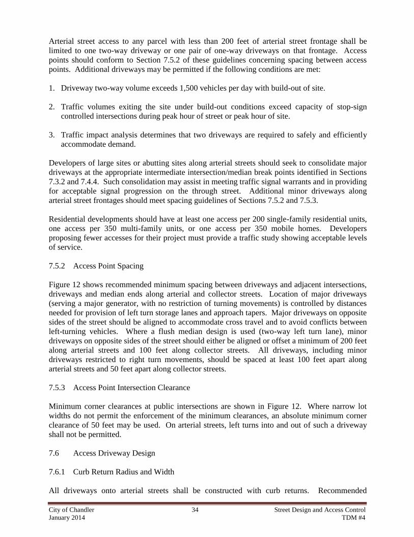
Arterial street access to any parcel with less than 200 feet of arterial street frontage shall be
limited to one two-way driveway or one pair of one-way driveways on that frontage. Access
points should conform to Section 7.5.2 of these guidelines concerning spacing between access
points. Additional driveways may be permitted if the following conditions are met:
1. Driveway two-way volume exceeds 1,500 vehicles per day with build-out of site.
2. Traffic volumes exiting the site under build-out conditions exceed capacity of stop-sign
controlled intersections during peak hour of street or peak hour of site.
3. Traffic impact analysis determines that two driveways are required to safely and efficiently
accommodate demand.
Developers of large sites or abutting sites along arterial streets should seek to consolidate major
driveways at the appropriate intermediate intersection/median break points identified in Sections
7.3.2 and 7.4.4. Such consolidation may assist in meeting traffic signal warrants and in providing
for acceptable signal progression on the through street. Additional minor driveways along
arterial street frontages should meet spacing guidelines of Sections 7.5.2 and 7.5.3.
Residential developments should have at least one access per 200 single-family residential units,
one access per 350 multi-family units, or one access per 350 mobile homes. Developers
proposing fewer accesses for their project must provide a traffic study showing acceptable levels
of service.
7.5.2 Access Point Spacing
Figure 12 shows recommended minimum spacing between driveways and adjacent intersections,
driveways and median ends along arterial and collector streets. Location of major driveways
(serving a major generator, with no restriction of turning movements) is controlled by distances
needed for provision of left turn storage lanes and approach tapers. Major driveways on opposite
sides of the street should be aligned to accommodate cross travel and to avoid conflicts between
left-turning vehicles. Where a flush median design is used (two-way left turn lane), minor
driveways on opposite sides of the street should either be aligned or offset a minimum of 200 feet
along arterial streets and 100 feet along collector streets. All driveways, including minor
driveways restricted to right turn movements, should be spaced at least 100 feet apart along
arterial streets and 50 feet apart along collector streets.
7.5.3 Access Point Intersection Clearance
Minimum corner clearances at public intersections are shown in Figure 12. Where narrow lot
widths do not permit the enforcement of the minimum clearances, an absolute minimum corner
clearance of 50 feet may be used. On arterial streets, left turns into and out of such a driveway
shall not be permitted.
7.6 Access Driveway Design
7.6.1 Curb Return Radius and Width
All driveways onto arterial streets shall be constructed with curb returns. Recommended

City of Chandler 35 Street Design and Access Control January 2014 TDM #4
dimensions are shown in Table 7.
TABLE 7
Recommended Driveway Dimensions Along Arterial And Collector Streets (F/C)
Arterial Street Collector Street
Parameter MF Res. Comm. Indus. MF Res. Comm. Indus.
Min. Width (1-way)
Min. Width (2-way)
Max. Width
Min. Corner Radius
Max. Corner Radius
16'
24’
30'
20'
20'
16'
24'
40'
20'
25'
16'
24'
40'
25'
30'
16'
24’
30'
NA
NA
16'
24'
40'
20'
25'
16'
24'
40'
25'
30'
Note: Abbreviations are MF RES. for Multi-Family Residential, Comm. for Commercial and
Indus. for Industrial land uses. Single family residences are not allowed direct access to arterial
streets. See Section 3.7 on page 14.
Where high pedestrian traffic is expected (e.g., in the central business district or close to a high
school, auditorium or library), a maximum width of 30 feet is desirable. Where large truck
movements are expected on a regular basis (5 or more trips per day), the corner radius and
driveway lane width should be designed to accommodate the truck turning path without
encroachment on the arterial street parallel traffic lane or the driveway opposing traffic lane.
7.6.2 Right Turn Deceleration Lanes
A right turn deceleration lane shall be provided at cross streets and driveways when
projected right turns into the site exceed 40 vehicles for a typical peak hour.
Where successive driveways warranting provision of right turn deceleration lanes are less than 400 feet apart (nearest edge to nearest edge), a continuous right turn lane rather than separate right turn lanes shall be constructed. Where a driveway warranting provision of a
right turn deceleration lane is located less than 450 feet in advance of an arterial cross street, a continuous right turn lane rather than separate right turn lanes shall be constructed.
The minimum right turn/deceleration lane length is 100 feet. (Also see Section 3.7 on page 14 and C.O.C. Std. Detail C-231.) The design of a continuous right-turn deceleration lane should not continue through a full-access intersection or driveway entrance (median break).
The City Transportation Engineer on a case-by-case basis may waive the right turn deceleration
lane requirement.
7.6.3 Access Drive Storage Space

City of Chandler 36 Street Design and Access Control January 2014 TDM #4
On-site geometrics are especially critical at drive-through facilities such as banks, fast-food restaurants and car washes. Sufficient stacking space should be provided to prevent blockage of arterial street access and egress. Where information about peak arrival rates and service times is not available, the preferred storage length in advance of a menu board or service bay is 150 feet (100 feet minimum).
Along an access drive from which left turns may be made onto an arterial street, cross-aisles must
be located at least 80 from the arterial street (right-of-way line to nearest edge of driveway). A
larger setback may be required where traffic impact studies indicate greater than a five-percent
probability of driveway blockage during the peak hour of a typical weekday.

City of Chandler 37 Street Design and Access Control January 2014 TDM #4
IS N
OT
AN
AR
TE
RIA
L S
TR
EE
T)
AL
ON
G A
RT
ER
IAL S
TR
EE
T
Cross Street
Minor Driveway
25
0' *
Minor Driveway
Minor Driveway
75
'
RA
ISE
D M
ED
IAN
15
0'
50
'
Minor Driveway
15
0' *
Minor Driveway
Minor Driveway
75
'RA
ISE
D M
ED
IAN
Minor Driveway
Cross Street
AL
ON
G C
OL
LE
CT
OR
ST
RE
ET
Major DrivewayMinor Driveway
Minor Driveway
10
0'
35
0' *
Co
rne
r cle
ara
nce
ma
y b
e r
ed
uce
d t
o a
min
imu
m o
f 1
00
' o
n a
pp
roa
ch
to
an
in
ters
ectio
n w
ith
no
po
ten
tia
l fo
r tr
aff
ic s
ign
al in
sta
llatio
n f
or
min
or
drive
wa
ys r
estr
icte
d t
o r
igh
t tu
rn m
ove
me
nts
on
ly.
* **C
orn
er
cle
ara
nce
sh
ou
ld b
e in
cre
ase
d t
o a
min
imu
m o
f 2
50
' w
he
red
rive
wa
y t
raff
ic v
olu
me
wa
rra
nts
a r
igh
t tu
rn la
ne
on
de
pa
rtu
re f
rom
inte
rse
ctio
n.
20
0'
45
0' *
15
0' **
10
0'
Minor Driveway
Major DrivewayMinor Driveway
FL
US
H M
ED
IAN
(35
0' IF
TH
E C
RO
SS
ST
RE
ET
FIGURE 12 - DRIVEWAY SPACING ALONG ARTERIAL AND COLLECTOR STREETS