Embed Size (px)
Citation preview
STIH)
STIHL Series 4140 powerhea d 19 99 -0 8
1. Introduction 1
2. Safety precautions 2
3. Specifications 3
3.1 Engine 33.2 Ignition system 33.3 Tightening torques 4
4. Cylinder and piston 5
4.1 Removal 54.2 Installation 64.3 Piston rings 7
5. Crankshaft / ball bearings 7
5.1 Oil seals 9
6 Leakage test 10
6.1 Preparations 106.2 Pressure test 116.3 Vacuum test 12
7. Ignition system 12
7.1 Ignition module 137.1.1 Ignition timing 137.1.2 Removal and
installation 137.2 Flywheel / fan wheel 14
8. Rewind starter 15
8.1 General 158.2 Starter cup 15
9. Special servicing tools 16
10. Service aids 17
11. Special accessories for the user 17
The "basic engine 4140" is used todrive a number of power tools:FS 45, 46, 55; FC 55; BG 45, 55, 65, 85; SH 55, 85; HS 45; HL 45.
Servicing procedures for specificmachine components are described in the handbook "Machine components 4140".
There are separate handbooks for servicing procedures for standardized parts and assemblies that are installed in several STIHL power tool models ("Standard Repairs, Trouble-shooting", "Carburetors"). Reference is made to these handbooks in the appropriatechapters in this manual.
You should make use of the illustrated parts lists while carryingout repair work. They show the installed positions of the individualcomponents and assemblies.
Refer to the latest edition of the relevant parts list to check the partnumbers of any replacement partsneeded. Parts lists on microficheand CD-ROM are always more upto date than printed lists.
A fault in the machine may haveseveral causes. To help locatethe fault, consult the trouble-shooting charts for all assembliesin the "Standard Repairs, Troubleshooting" handbook.
Contents 1. Introduction
Basic engine 4140 1

Refer to the "Technical information" bulletins for engineering changes which have been introduced since publication of this service manual.Technical information bulletinsalso supplement the parts list untila revised edition is issued.
Special servicing tools mentionedin the descriptions are listed in thelast chapter of this manual. Usethe part numbers to identify thetools in the "STIHL Special Tools"manual. The manual lists all special servicing tools currentlyavailable from STIHL.
Symbols are included in the textand pictures for greater clarity.The meanings are as follows:
In the descriptions:
• = Action to be taken as shown in the illustration (above the text)
- = Action to be taken that is not shown in the illustration (above the text)
In the illustrations:
= Pointer
= Direction of movement
Service manuals and all technicalinformation bulletins describing engineering changes are intendedexclusively for the use of STIHLservicing dealers. They must notbe passed on to third parties.
Servicing and repairs of powertools with shaft (FS, FC, HL) aremade considerably easier if themachine is mounted on assemblystand (2) 5910 890 3100 with theaid of clamp (1) 5910 890 8800.
Secure the clamp to the assemblystand with two washers and twoM8 nuts. The complete unit canthen be swivelled to the best position for the ongoing repair,thus leaving both hands free.
Always use original STIHL replacement parts.They can be identified by theSTIHL part number, the � logo and the STIHL parts symbol �. The symbol may appear alone onsmall parts.
If the machine is started up in thecourse of repairs or maintenancework, observe all local and specificnational safety regulations, as wellas the safety precautions and warnings in the owner’s manual.
Petrol is a highly inflammable fueland can be explosive in certainconditions.
Improper handling may result inburns or other serious injuries.
Warning! Do not smoke or bringany fire or flame near the fuel. Allwork with fuel must be performedoutdoors only. Spilled fuel mustbe wiped away immediately.
2. Safety precautions
VA
232R
A00
12
1
2 Basic engine 4140

3.1 Engine STIHL single-cylinder two-stroke engine with special impregnated cylinder bore
Displacement: 27.2 cm3 Bore: 34 mmStroke: 30 mmEngine power to ISO 8893 0.75 kW (1 HP)at 7000 rpm:Max. permissible engine speed without cutting tool (cut-off speed): 9500 + 800 rpmIdle speed: 2800 + 300 rpmBearings: Crankshaft supported in
heavy-duty deep-groove ball bearings, needle cages on small and big ends
Piston pin diameter: 8 mmClutch: Centrifugal clutch without liningsClutch engages at: 3800 rpmCrankcase leakage testat gauge pressure: pü = 0.5 bar (5 kPa)under vacuum: pu = 0.5 bar (5 kPa)
3.2 Ignition system Type: Electronic magneto ignition (breakerless) with integral trigger unit
Air gap: 0.15 ... 0.45 mmSpark plug (suppressed): Bosch WSR 6F
NGK BPMR 7 AChampion RCJ 6Y
Electrode gap: 0.5 mm
3. Specifications
Basic engine 4140 3

DG and P (Plastoform) screws are used in polymer and lightmetal components. These screws form a perma-nent thread when they are installed for the first time. They can be removed and installed as often as necessarywithout impairing the strength of the screwed assembly, provided the specified tightening torque is observed.For this reason it is essential to use a torque wrench.
Fastener Thread size For component Tightening torque Remarks(Nm)
Spline screw IS-DG5x60 Engine pan / crankcase / cylinder 9,0 2)Spline screw IS-DG5x60 Muffler / cylinder 9,0 2)
M8 Starter cup 17,0M14x1,25 Spark plug 20,0
Spline screw IS-DG4x20 Ignition module / cylinder 4,5 2)
Proceed as follows to fit a DG or P screw in an existing thread:
– Place the DG or P screw in the hole and turn it counterclockwise until it drops down slightly.– Tighten the screw clockwise to the specified torque.
This procedure ensures that the screw engages properly in the existing thread and does not form a new threadand weaken the assembly.
Note: Power screwdriver speed settings for polymer: Plastoform screws max. 600 rpm DG screws max. 500 rpm
Important! Do not confuse screws with and without underhead locking teeth.
1) With locking teeth2) Without locking teeth
3.3 Tightening torques
4 Basic engine 4140

Always check and, if necessary, repair the fuel system, carburetor,air filter and ignition system beforelooking for faults on the engine.
Troubleshooting chart – see "Standard Repairs, Troubleshooting" handbook.
- Remove housing parts, muffler,ignition module and spacer flange – see handbook "Components, Basic Engine 4140".
- Unscrew the spark plug.
• Fit jaws (1) 0000 893 3700 withNo. 2 profile on puller (2) 5910 890 4400.
• Fit screw bush (3) 1108 8934500 on spindle.
• To ensure that the crankcaseand engine pan do not comeapart when the cylinder is removed, hold both parts together with the puller.
• Unscrew cylinder base screws.
- Clamp puller in a vice.
- Pull cylinder off piston.
- Inspect cylinder and replace it ifnecessary.
- If a new cylinder has to be installed, always fit the matchingpiston as well. New cylindersare only available with piston.
- Remove cylinder gasket.
- Take snap ring (B8x0.7) out ofgroove on starter cup side.
Note: The hookless snap ring onthe flywheel side remains in thegroove.
• Drive piston pin out of piston witha 7 mm drift.
Note: If the piston pin is stuck,tap the end of the drift lightly witha hammer if necessary. Hold thepiston steady during this process,so that jolts are not transmitted tothe connecting rod.
- Remove piston from connectingrod.
- Inspect needle cage and replacecrankshaft if necessary, see 5.1.
Note: One (FS 45) or two (FS 45, 55) piston ring(s) is/areused depending on the model inquestion.
- Inspect piston rings and replaceif necessary, see 4.3.
4. Cylinder and piston4.1 Removal
VA
232R
A11
5
VA
232R
A11
7
VA
232R
A11
4
VA
232R
A11
6
VA
232R
A11
8
13
1
2
Basic engine 4140 5

Thoroughly clean gasket seatingsurface.
- Lubricate needle cage in connecting rod with oil.
• To simplify assembly, heat the piston and slip it over the connecting rod.
• Installed position of piston:1 = Marking = exhaust side2 = Flywheel
• Fit the piston pin in position and use assembly drift (1) 1114 893 4700 to push it as faras possible against the hooklesssnap ring (the pin slides homeeasily if the piston is hot).
- Fit snap ring (B8x0.7) so that itsgap is on the vertical axis of thepiston (pointing up or down).
• Fit new cylinder gasket.
• Lubricate piston and piston ringswith oil. Rest piston (1) on wooden assembly block (2) 1108 893 4800.
Note: One (FS 45) or two (FS 45, 55) piston ring(s) is/areused depending on the model inquestion.
• Position the piston rings so thatthe radii at the ring gap meet atthe fixing pin in the piston groovewhen the rings are compressed.
• Use clamping strap (1) 0000 893 2600 to compress piston ring around piston.
- Check that piston rings are correctly positioned.
- Lubricate inside of cylinder withoil and line it up in its subsequentposition when installed. The piston rings may break if this point is disregarded.
VA
232R
A12
0
1
4.2 Installation
VA
1
232R
A11
9
2
VA
232R
A12
2
1
2
VA
232R
A12
1
VA
232R
A12
4
1
VA
232R
A12
3
6 Basic engine 4140
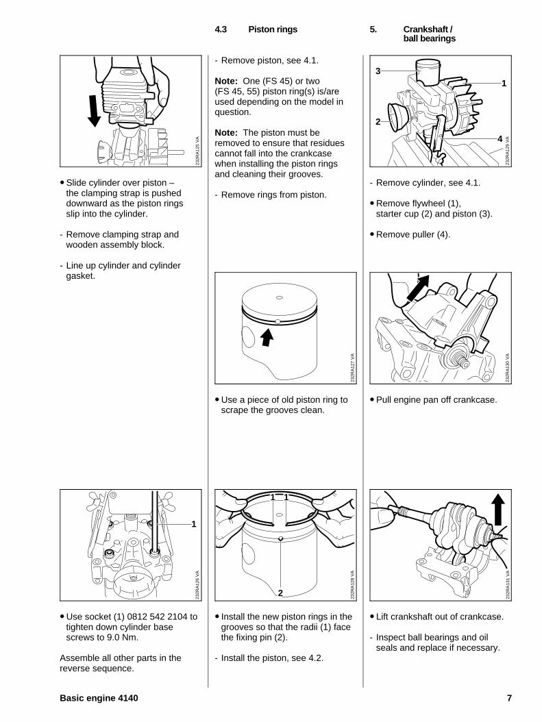
• Slide cylinder over piston – the clamping strap is pusheddownward as the piston ringsslip into the cylinder.
- Remove clamping strap and wooden assembly block.
- Line up cylinder and cylinder gasket.
• Use socket (1) 0812 542 2104 totighten down cylinder basescrews to 9.0 Nm.
Assemble all other parts in the reverse sequence.
- Remove piston, see 4.1.
Note: One (FS 45) or two (FS 45, 55) piston ring(s) is/areused depending on the model inquestion.
Note: The piston must be removed to ensure that residuescannot fall into the crankcasewhen installing the piston ringsand cleaning their grooves.
- Remove rings from piston.
• Use a piece of old piston ring toscrape the grooves clean.
• Install the new piston rings in thegrooves so that the radii (1) facethe fixing pin (2).
- Install the piston, see 4.2.
- Remove cylinder, see 4.1.
• Remove flywheel (1), starter cup (2) and piston (3).
• Remove puller (4).
• Pull engine pan off crankcase.
• Lift crankshaft out of crankcase.
- Inspect ball bearings and oil seals and replace if necessary.
4.3 Piston rings 5. Crankshaft /ball bearings
VA
232R
A13
0
VA
232R
A12
7
VA
232R
A12
9
2
1
4
3
VA
232R
A12
5
VA
232R
A13
1
VA
232R
A12
8
2
1 1
VA
232R
A12
6
1
Basic engine 4140 7
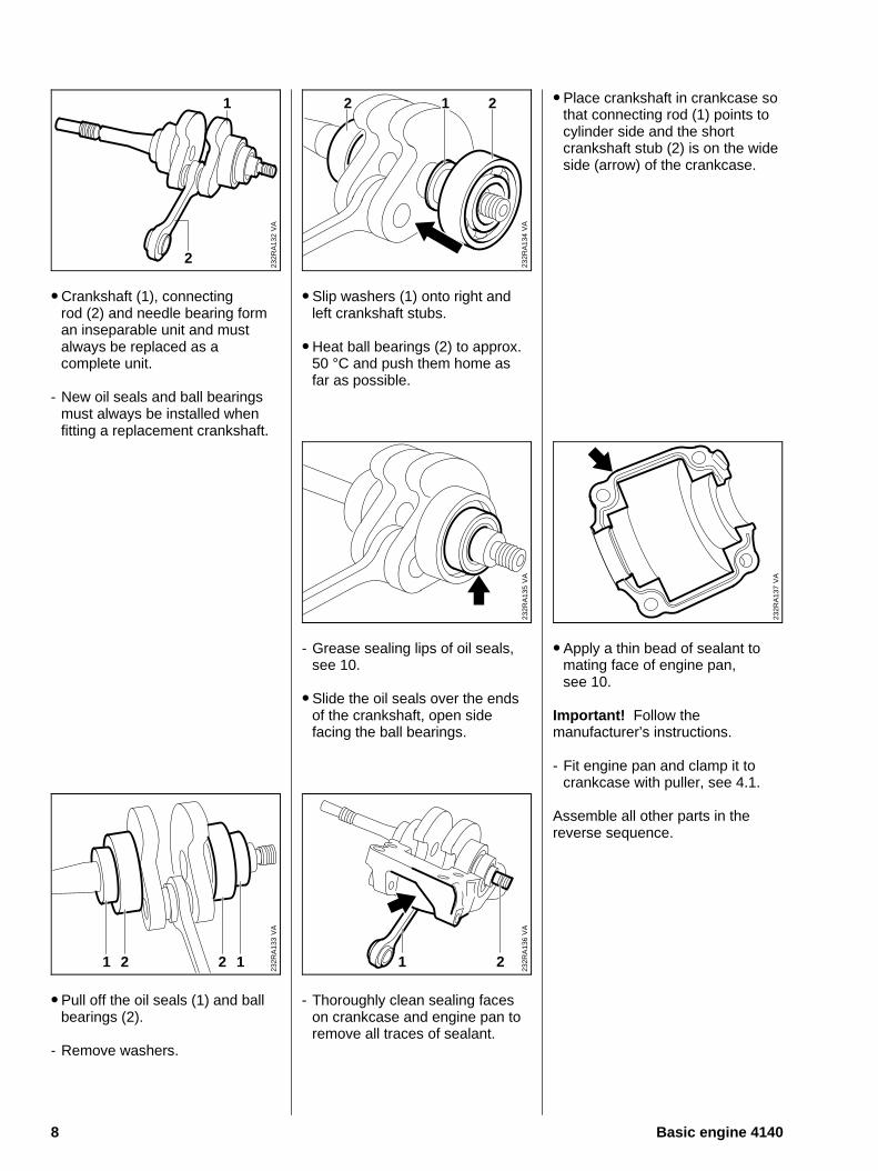
• Crankshaft (1), connecting rod (2) and needle bearing forman inseparable unit and must always be replaced as a complete unit.
- New oil seals and ball bearingsmust always be installed when fitting a replacement crankshaft.
• Pull off the oil seals (1) and ballbearings (2).
- Remove washers.
• Slip washers (1) onto right andleft crankshaft stubs.
• Heat ball bearings (2) to approx.50 °C and push them home asfar as possible.
- Grease sealing lips of oil seals,see 10.
• Slide the oil seals over the endsof the crankshaft, open side facing the ball bearings.
- Thoroughly clean sealing faceson crankcase and engine pan toremove all traces of sealant.
• Place crankshaft in crankcase sothat connecting rod (1) points tocylinder side and the shortcrankshaft stub (2) is on the wideside (arrow) of the crankcase.
• Apply a thin bead of sealant tomating face of engine pan, see 10.
Important! Follow the manufacturer’s instructions.
- Fit engine pan and clamp it tocrankcase with puller, see 4.1.
Assemble all other parts in the reverse sequence.
VA
232R
A13
7
VA
232R
A13
5V
A23
2RA
134
22 1
VA
232R
A13
2
1
2
VA
232R
A13
6
1 2
VA
232R
A13
3
21 12
8 Basic engine 4140
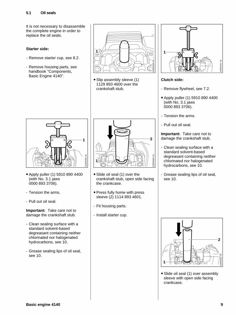
It is not necessary to disassemblethe complete engine in order to replace the oil seals.
Starter side:
- Remove starter cup, see 8.2.
- Remove housing parts, seehandbook "Components, Basic Engine 4140".
• Apply puller (1) 5910 890 4400(with No. 3.1 jaws 0000 893 3706).
- Tension the arms.
- Pull out oil seal.
Important: Take care not to damage the crankshaft stub.
- Clean sealing surface with astandard solvent-based degreasant containing neitherchlorinated nor halogenated hydrocarbons, see 10.
- Grease sealing lips of oil seal,see 10.
• Slip assembly sleeve (1) 1129 893 4600 over the crankshaft stub.
• Slide oil seal (1) over the crankshaft stub, open side facingthe crankcase.
• Press fully home with press sleeve (2) 1114 893 4601.
- Fit housing parts.
- Install starter cup.
Clutch side:
- Remove flywheel, see 7.2.
• Apply puller (1) 5910 890 4400(with No. 3.1 jaws 0000 893 3706).
- Tension the arms.
- Pull out oil seal.
Important: Take care not to damage the crankshaft stub.
- Clean sealing surface with astandard solvent-based degreasant containing neitherchlorinated nor halogenated hydrocarbons, see 10.
- Grease sealing lips of oil seal,see 10.
• Slide oil seal (1) over assemblysleeve with open side facingcrankcase.
5.1 Oil seals
VA
232R
A04
0
2
1
VA
232R
A03
8
1
VA
232R
A04
1
1
VA
232R
A03
9
1
VA
232R
A04
2
2
1
Basic engine 4140 9

• Press fully home with press sleeve (2) 1120 893 2400.
- Fit flywheel.
Leaks are usually caused by defective oil seals or gaskets andcracks in castings of the spacerflange. Such faults allow supplementary air to enter the engine and thus upset the fuel-airmixture.
This makes adjustment of the prescribed idle speed difficult, ifnot impossible.
Moreover, the transition from idlespeed to part or full throttle is notsmooth.
The crankcase can be checkedthoroughly for leaks with the carburetor and crankcase testerand the vacuum pump.
- Remove shroud, carburetor andstarter cover, see handbook "Machine components, 4140".
- Set piston to top dead centre(T.D.C.). This can be checkedthrough the inlet port.
- Check that the spark plug is properly tightened down.
• Fit a new gasket on spacer flange.
• Fit test flange (1) 1128 850 4200.
Fit nuts (2) and tighten down to3.5 Nm.
6. Leakage test 6.1 Preparations
VA
232R
A03
2V
A23
2RA
033
1
22
10 Basic engine 4140
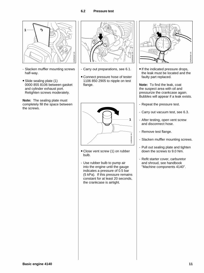
- Slacken muffler mounting screwshalf-way.
• Slide sealing plate (1) 0000 855 8106 between gasketand cylinder exhaust port. Retighten screws moderately.
Note: The sealing plate must completely fill the space betweenthe screws.
- Carry out preparations, see 6.1.
• Connect pressure hose of tester1106 850 2905 to nipple on testflange.
• Close vent screw (1) on rubberbulb.
- Use rubber bulb to pump air into the engine until the gauge indicates a pressure of 0.5 bar (5 kPa). If this pressure remainsconstant for at least 20 seconds,the crankcase is airtight.
• If the indicated pressure drops,the leak must be located and thefaulty part replaced.
Note: To find the leak, coat the suspect area with oil and pressurize the crankcase again.Bubbles will appear if a leak exists.
- Repeat the pressure test.
- Carry out vacuum test, see 6.3.
- After testing, open vent screwand disconnect hose.
- Remove test flange.
- Slacken muffler mounting screws.
- Pull out sealing plate and tightendown the screws to 9.0 Nm.
- Refit starter cover, carburetorand shroud, see handbook "Machine components 4140".
6.2 Pressure test
VA
232R
A03
5
VA
232R
A03
4
1
VA
143R
A04
6
1
232R
A03
6
0
0,2
0,4 0,6
0,8
1,0
VA
Basic engine 4140 11

Oil seals tend to fail when subjected to a vacuum, i.e. thesealing lip lifts away from thecrankshaft during the piston’s induction stroke because there is no internal counterpressure.
An additional test can be carriedout with the vacuum pump to detect this kind of fault.
- Carry out preparations, see 6.1.
• Connect suction hose of vacuumpump 0000 850 3501 to nippleon test flange.
• Close vent screw (1) on pump cylinder.
• Operate lever (2) until the gauge (3) shows a vacuum of0.5 bar (5 kPa).
Note: If the vacuum reading remains constant or rises to nomore than 0.3 bar (3 kPa) within20 seconds, it may be assumedthat the oil seals are in good condition. However, if the pressure continuesto rise (reduced vacuum in thecrankcase), the oil seals must bereplaced.
- After testing, open vent screwand disconnect hose.
- Remove test flange.
- Slacken muffler mounting screws.
- Pull out sealing plate and tightendown the screws to 9.0 Nm.
- Refit carburetor and shroud, see handbook "Machine components 4140".
Warning! Exercise extreme caution when carrying out maintenance and repair work ortroubleshooting on the ignition system. The high voltages whichoccur can cause serious or evenfatal accidents!
Troubleshooting on the ignition system should always begin withthe spark plug. See "Standard Repairs, Troubleshooting" handbook.
Note: The electronic (breakerless) ignition system basically consists of an ignition module (1) and flywheel (2).
6.3 Vacuum test 7. Ignition system
VA
232R
A03
5V
A23
2RA
037
1
2
3
VA
232R
A04
3
2
1
12 Basic engine 4140

The ignition module accommo-dates all the components requiredto control ignition timing.
There are two electrical connections on the coil body:
A. The high-voltage output (1)with ignition lead (2)
B. The connector tag (3) for the short-circuit wire
Accurate testing of the ignition module is only possible with sophisticated test equipment. Forthis reason, it is only necessary tocarry out a spark test in the workshop. A new ignition modulemust be installed if an ignitionspark is not obtained (after checking that wiring and stopswitch are in good condition).
Ignition timing is not adjustable.
Since there is no mechanical wearin these systems, ignition timingcannot get out of adjustment.However, an internal fault in thecircuit can alter the switching pointin such a way that a spark test willstill show the system to be in orderalthough timing is outside the permissible tolerance. This will impair engine starting and runningbehaviour. - Remove shroud or relevant
housing part, see handbook "Machine components 4140".
• Disconnect short-circuit wire (1)and ground wire (2) from ignitionmodule.
- Pull boot off spark plug.
• Undo screws.
- Remove ignition module.
7.1 Ignition module 7.1.1 Ignition timing 7.1.2 Removal and installation
VA
232R
A00
5
2
1
VA
232R
A04
4
3
2
1
VA
232R
A04
5
Basic engine 4140 13

Note: The ignition lead is moulded to the ignition module.
- Place ignition module in positionand insert screws, but do nottighten them down yet.
• Secure connector tag (1) for ground wire with upper screw.
• Slide setting gauge (2) 1127 890 6400 between arms of ignition module and flywheelmagnet poles.
- Press ignition module againstsetting gauge and tighten downthe mounting screws to a torqueof 4.5 Nm.
Assemble all other parts in the reverse sequence.
Removing the flywheel:
- Remove clutch, see handbook "Components, Basic Engine 4140".
• Lightly tap the end of the crankshaft stub with a rubbermallet to free the flywheel.
- Pull off the flywheel.
Note: There must not be anycracks or other signs of damage visible in the flywheel (1) and magnet poles (2), otherwise theflywheel must be replaced.
Installing the flywheel:
Important: Degrease the stub ofthe crankshaft and bore of theflywheel hub with a standard commercial solvent-based degreasant containing neither chlorinated nor halogenated hydrocarbons, see 10.
- Fit flywheel.
Note: Check position of slot.
- Install clutch, see handbook "Components, Basic engine 4140".
- Pull locking strip out of cylinder.
- Fit spark plug and torque downto 20 Nm.
• If the spark plug comes with a separate terminal nut, alwayscheck that the nut is securelytightened down on the threadand retighten if necessary.
- Fit boot on spark plug.
7.2 Flywheel / fan wheel
VA
232R
A04
6
2
1
232R
A04
7V
A
VA
250R
A00
8
VA
232R
A04
8
1
2
14 Basic engine 4140

If the action of the starter rope becomes very stiff and the rope rewinds very slowly or incompletely, it may be assumedthat the starter mechanism is in order but plugged with dirt. Atvery low outside temperatures, thelubricating oil on the rewind springmay thicken and cause the springwindings to stick together. Thishas a detrimental effect on the function of the starter mechanism.In such a case, it is sufficient to apply a few drops of paraffin (kerosine) to the rewind spring.
Then carefully pull out the starterrope several times and allow it torewind until its normal smooth action is restored.
If clogged with dirt or pitch, the entire starter mechanism, including the rewind spring, mustbe removed and disassembled.Take particular care when removing the spring.
Wash all parts in paraffin or whitespirit.
Lubricate the rewind spring andstarter post with STIHL special lubricant, see 10, before installing.
- Remove starter cover, see handbook "Components, Basic Engine 4140".
- Unscrew spark plug.
• Fit locking strip (1) 4221 893 5900.
• Unscrew starter cup.
• Fit starter cup and torque downto 17.0 Nm.
Install all other parts in the reversesequence.
8. Rewind starter8.1 General 8.2 Starter cup
VA
232R
A06
5V
A23
2RA
064
1
VA
232R
A06
6
Basic engine 4140 15
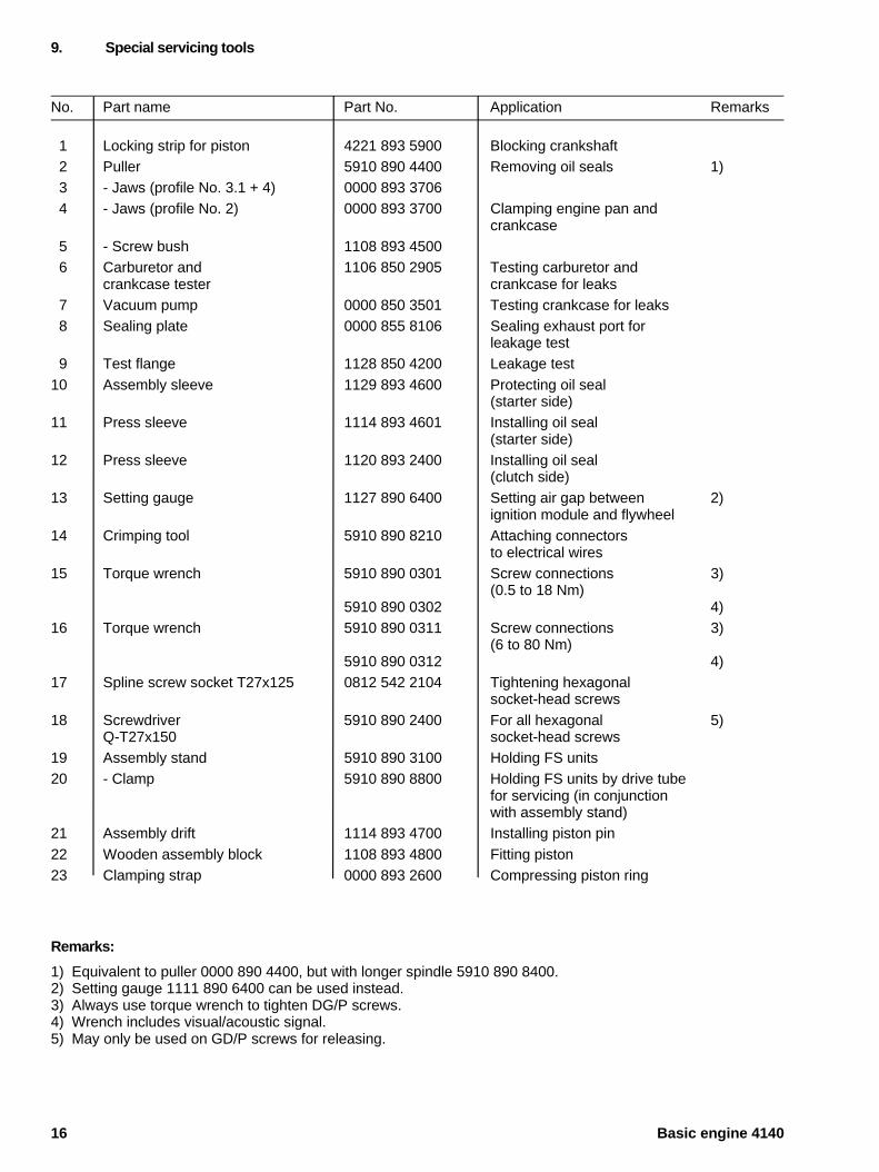
No. Part name Part No. Application Remarks
1 Locking strip for piston 4221 893 5900 Blocking crankshaft 2 Puller 5910 890 4400 Removing oil seals 1) 3 - Jaws (profile No. 3.1 + 4) 0000 893 3706 4 - Jaws (profile No. 2) 0000 893 3700 Clamping engine pan and
crankcase 5 - Screw bush 1108 893 4500 6 Carburetor and 1106 850 2905 Testing carburetor and
crankcase tester crankcase for leaks 7 Vacuum pump 0000 850 3501 Testing crankcase for leaks 8 Sealing plate 0000 855 8106 Sealing exhaust port for
leakage test 9 Test flange 1128 850 4200 Leakage test10 Assembly sleeve 1129 893 4600 Protecting oil seal
(starter side)11 Press sleeve 1114 893 4601 Installing oil seal
(starter side)12 Press sleeve 1120 893 2400 Installing oil seal
(clutch side)13 Setting gauge 1127 890 6400 Setting air gap between 2)
ignition module and flywheel14 Crimping tool 5910 890 8210 Attaching connectors
to electrical wires15 Torque wrench 5910 890 0301 Screw connections 3)
(0.5 to 18 Nm)5910 890 0302 4)
16 Torque wrench 5910 890 0311 Screw connections 3)(6 to 80 Nm)
5910 890 0312 4)17 Spline screw socket T27x125 0812 542 2104 Tightening hexagonal
socket-head screws18 Screwdriver 5910 890 2400 For all hexagonal 5)
Q-T27x150 socket-head screws19 Assembly stand 5910 890 3100 Holding FS units20 - Clamp 5910 890 8800 Holding FS units by drive tube
for servicing (in conjunction with assembly stand)
21 Assembly drift 1114 893 4700 Installing piston pin22 Wooden assembly block 1108 893 4800 Fitting piston23 Clamping strap 0000 893 2600 Compressing piston ring
Remarks:
1) Equivalent to puller 0000 890 4400, but with longer spindle 5910 890 8400.2) Setting gauge 1111 890 6400 can be used instead.3) Always use torque wrench to tighten DG/P screws.4) Wrench includes visual/acoustic signal.5) May only be used on GD/P screws for releasing.
9. Special servicing tools
16 Basic engine 4140
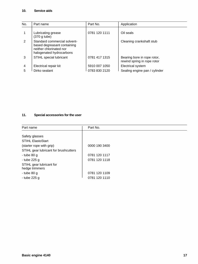
No. Part name Part No. Application
1 Lubricating grease 0781 120 1111 Oil seals(370 g tube)
2 Standard commercial solvent- Cleaning crankshaft stubbased degreasant containing neither chlorinated nor halogenated hydrocarbons
3 STIHL special lubricant 0781 417 1315 Bearing bore in rope rotor, rewind spring in rope rotor
4 Electrical repair kit 5910 007 1050 Electrical system 5 Dirko sealant 0783 830 2120 Sealing engine pan / cylinder
11. Special accessories for the user
Part name Part No.
Safety glassesSTIHL ElastoStart (starter rope with grip) 0000 190 3400STIHL gear lubricant for brushcutters- tube 80 g 0781 120 1117- tube 225 g 0781 120 1118STIHL gear lubricant for hedge trimmers- tube 80 g 0781 120 1109- tube 225 g 0781 120 1110
10. Service aids
Basic engine 4140 17

englisch / english
0455 931 0123 M12. H9. Sä. Printed in Germany


![STIHL FS 38, 45, 45 C, 45 L, (UVDW]WHLOOLVWH 6SDUH 3DUWV ...€¦ · stihl fs 38, 45, 45 c, 45 l, 46, 46 c (4140) (uvdw]whloolvwh 6sduh 3duwv /lvw /lvwh ghv slÙfhv $1'5($6 67,+](https://img.dokumen.tips/doc/110x75/5f7f884b9cc1ca3be32707d7/stihl-fs-38-45-45-c-45-l-uvdwwhloolvwh-6sduh-3duwv-stihl-fs-38-45-45.jpg)