Embed Size (px)
Citation preview

STANDARD SPECIFICATION – ROADWORKS
DoI REFERENCE TEXT – October 2016
Page 0
2017 standard specification
for roadworks
miscellaneous provisions ■ provision for traffic ■
clearing grubbing and rehabilitation ■ earthworks ■
conformance testing ■ pavements and shoulders ■
stabilisation ■ spray sealing ■ dense graded asphalt ■
slurry surfacing ■ miscellaneous concrete works ■
drainage works ■ protection works ■
road furniture and traffic control devices ■ pavement marking ■
landscape ■ ducting and conduits ■ traffic control signals ■
traffic counting stations ■ street lighting ■
directional boring ■ measurement and payment ■
referenced australian standards ■ other referenced authorities and documents ■
acts regulations and codes ■ civil standard drawings for roadworks ■
nt climate zones table ■
this document specifies the general standards of materials and workmanship required by the department
for construction of civil road network assets

This page deliberately left blank

STANDARD SPECIFICATION FOR ROADWORKS
NTG REFERENCE TEXT – DECEMBER 2016
Page 1
PO Box 61
Palmerston NT 0831
ABOUT THIS SPECIFICATION
This document was prepared by the Department of Infrastructure, Planning and Logistics (DIPL) and specifies the general standards of materials and workmanship required by the Department for roadworks. It brings together standard terminology and methods for roadworks work across all regions of the Northern Territory.
This document is designed to be used as a reference document for roadworks projects. It is to be read in conjunction with the Project Specific Requirements section of the Request for Tender document and the Drawings, if any. The Standards quoted are current as of September 2016.
The text has been edited to specify only the types of roadworks performed by the Department and is applicable to all regions of the Northern Territory. The text has been developed through consultation with Departmental officers with extensive experience in civil works in the Northern Territory.
This Standard Specification will remain unchanged until an updated version is published.
This specification is also available electronically in PDF from the Department’s Specification Services website: https://infrastructure.nt.gov.au/specification-services/technical-specifications/roads .
Louise McCormick
General Manager Transport and Civil Services
December 2016

STANDARD SPECIFICATION FOR ROADWORKS
NTG REFERENCE TEXT – DECEMBER 2016
Page 2
INFORMATION
For further information regarding this Standard Specification contact:-
Manager Specification Services
Department of Infrastructure, Planning and Logistics
PO Box 61
Palmerston NT 0831
Telephone: (08) 8946 5021
Email: [email protected]
Third edition - December 2016

STANDARD SPECIFICATION FOR ROADWORKS
NTG REFERENCE TEXT – DECEMBER 2016
Page 3
STANDARD SPECIFICATION FOR ROADWORKS
2017
REFERENCE TEXT
REFERENCE
Read this Standard Specification in conjunction with the Project Specific Requirements and Drawings, if any. Only those parts of the Standard Specification which refer to the works being carried out apply in addition to those items listed in the Schedule of Rates which is attached to the Response Schedules for the particular Contract. This document may be used as a blanket reference specification referring generally to the standards of materials and workmanship required by the Department for roadworks.
PROJECT SPECIFIC REQUIREMENTS
The selection of specific items or materials for the works being carried out are those items listed in the Schedule of Rates in the Response Schedules for the particular Contract and any items specified in the Project Specific Requirements section of the Request for Tender document. Any additional work or any changes to the reference specification will be specified in the Project Specific Requirements section.
PRECEDENCE
Any provision in the Request for Tender or on the project drawings shall override any conflicting provision in this Standard Specification.
HOLD AND WITNESS POINTS
These apply whether Project Control or Quality Assurance is included in the project or not. Refer to the definitions of Hold Points and Witness Points in the Miscellaneous Provisions section of this Standard Specification. Tables of Hold and Witness Points are available via https://infrastructure.nt.gov.au/specification-services/technical-specifications/roads .
SITE COPY
Retain a copy of this document on site for the duration of the works.
COPYRIGHT
This Standard Specification is based on the Department’s Roadworks Master Specification. This document is copyright protected and the property of the Government of the Northern Territory and must not be retained, copied, or used without authority.
ISSN 2203-4188 Print edition
ISSN 2204-8936 On-line edition

STANDARD SPECIFICATION FOR ROADWORKS
NTG REFERENCE TEXT – DECEMBER 2016
Page 4
This page deliberately left blank.

STANDARD SPECIFICATION FOR ROADWORKS
NTG REFERENCE TEXT – DECEMBER 2016
Page 5
STANDARD SPECIFICATION FOR ROADWORKS
2017
REFERENCE TEXT
CONTENTS
1. MISCELLANEOUS PROVISIONS ......................................................................................................... 7
2. PROVISION FOR TRAFFIC ................................................................................................................ 14
3. CLEARING, GRUBBING AND REHABILITIATION ............................................................................. 25
4. EARTHWORKS ................................................................................................................................... 27
5. CONFORMANCE TESTING................................................................................................................ 33
6. PAVEMENTS AND SHOULDERS ...................................................................................................... 47
7. STABILISATION .................................................................................................................................. 52
8. SPRAY SEALING ................................................................................................................................ 56
9. DENSE GRADED ASPHALT............................................................................................................... 69
10 SLURRY SURFACING ........................................................................................................................ 79
11 MISCELLANEOUS CONCRETE ......................................................................................................... 83
12 DRAINAGE WORKS ........................................................................................................................... 87
13 PROTECTION WORKS ....................................................................................................................... 92
14 ROAD FURNITURE AND TRAFFIC CONTROL DEVICES ................................................................ 97
15 PAVEMENT MARKING ..................................................................................................................... 104
16 LANDSCAPE ..................................................................................................................................... 110
17 DUCTING AND CONDUITS .............................................................................................................. 121
18 TRAFFIC CONTROL SIGNALS AND INTELLIGENT TRANSPORT SYSTEMS .............................. 122
19 TRAFFIC COUNTING STATIONS .................................................................................................... 125
20 STREET LIGHTING ........................................................................................................................... 128
21 DIRECTIONAL BORING ................................................................................................................... 131
22 PROTECTIVE COATINGS ................................................................................................................ 132
23 MEASUREMENT AND PAYMENT .................................................................................................... 147
24 REFERENCED AUSTRALIAN STANDARDS ................................................................................... 157
25 OTHER REFERENCED AUTHORITIES AND DOCUMENTS .......................................................... 166
26 ACTS, REGULATIONS AND CODES ............................................................................................... 168
27 CIVIL STANDARD DRAWINGS FOR ROADWORKS ...................................................................... 169
28 NORTHERN TERRITORY CLIMATE ZONES TABLE ...................................................................... 180

STANDARD SPECIFICATION FOR ROADWORKS
NTG REFERENCE TEXT – DECEMBER 2016
Page 6
This page deliberately left blank.

MISCELLANEOUS PROVISIONS
STANDARD SPECIFICATION FOR ROADWORKS
NTG REFERENCE TEXT – DECEMBER 2016
Page 7
1. MISCELLANEOUS PROVISIONS
STANDARDS 1.1
Conform to the following Standards, Acts and Publications unless specified otherwise:
AS 1100(set) Technical drawing AS 1348 Road and traffic engineering -
Glossary of terms AS 1742 Manual of uniform traffic control
devices Set AS 2187.1 Explosives - Storage, transport
and use - Storage AS 2187.2 Explosives - Storage, transport
and use - Use of explosives
NTMTM NT Materials Testing Manual
NTCP NT Codes of Practice
NTTM NT Test Methods
Aboriginal Land Rights (NT) Act Mining Titles Act and Mining Management Act Workplace Health and Safety (National Uniform Legislation) Act and Regulations Dangerous Goods Act and Regulations Railways of Australia (ROA) Code - Installation of Other Parties Services and Pipelines Within Railway Boundaries The Water Act The Energy Pipelines Act (NT Gas) ACMA Australian Communications Media Authority - any Standards, Acts, controls specifically required. Refer to ACMA directly. Standard Specification for Environmental Management, DIPL publication
Standards in Conflict 1.1.1
Where conflict arises between a referenced standard and particular clauses of this specification this specification prevails.
Overseas Standards 1.1.2
Where no Australian Standard exists standards published by the British Standards Institute (BSI) or the American Society for Testing Materials are referenced.
Currency of Standards 1.1.3
Use Standards, and their amendments, current 3 months before the date for the close of tenders except where different editions and/or amendments are required by statutory authorities, including, but not limited to, NATA and the National Construction Code including the Building Code of Australia.
DEFINITIONS 1.2The terms used in this specification are in accordance with the definitions laid down in AS 1348 unless specified otherwise in the Definitions clauses. DRY DENSITY RATIO: The percentage ratio of the field dry density of a material to the modified maximum dry density of
that material. This property is also termed Relative Compaction. EXTRACTION AREA: An excavation outside the formation limits for obtaining fill, gravel, rock and rubble. Also known as Borrow Pit. HOLD POINT: Obtain the Superintendent’s written approval for that particular part of the works.
PSRs
Project Specific Requirements:
- appear in RFT and refer to this document which is the Technical Specification for the project which is the subject of the RFT,
- detail what selections have been made where selections need to be made
- may include amendments to specified requirements published in this Standard Specification to tailor the specification to suit the project which is the subject of the RFT.
RFT: Request for Tender. Technical specifications and conditions applicable to an RFT are equally applicable to an RFQ (Request for Quotation). SHALL: Indicates a mandatory requirement unless the context clearly indicates otherwise. WITNESS POINT: Give the Superintendent sufficient prior notice, in writing, of an action so that that part of the works may be inspected.
THE CONDITIONS OF TENDER AND 1.3CONDITIONS OF CONTRACT
The Conditions of Tender and the Conditions of Contract contain additional requirements which apply to works carried out under any contract awarded by NT Government, including any works carried out using this specification.
ENVIRONMENTAL MANAGEMENT 1.4
The Standard Specification for Environmental Management applies for all construction and demolition work for building and civil works carried out by or on behalf of the Northern Territory Government. The Standard Specification for Environmental Management takes precedence over this specification. A copy of that document is available at: https://infrastructure.nt.gov.au/specification-services/technical-specifications/environmental-management .
ESTABLISHMENT 1.5
General 1.5.1
Allow in the tender for establishment on site, including, but not necessarily limited to, the following:

MISCELLANEOUS PROVISIONS
STANDARD SPECIFICATION FOR ROADWORKS
NTG REFERENCE TEXT – DECEMBER 2016
Page 8
MOBILISATION: Transportation and establishment on site, of all the requirements to complete the work. DEMOBILISATION: Removal and transportation from site of all temporary and construction facilities and equipment. Restoration of the site, on Practical Completion of the works, compatible with environs. ONGOING COSTS: All indirect costs associated with the contract. Provide, on request, details substantiating the amount shown in the Schedule of Rates.
PROJECT SPECIFIC REQUIREMENTS 1.6
Comply with all provisions in PROJECT SPECIFIC REQUIREMENTS (PSRs) in the Request For Tender (RFT) or on the project drawings. Any conflicts must be advised in writing to the Superintendent for clarification.
CAMP SITE/COMPOUND/WORKSHOP 1.7– HOLD POINT
Hold Point - Obtain written permission from the owner or lessee of the land.
Pay all costs associated with the use of the site(s).
Maintain all facilities in good condition.
Remove all facilities, unless otherwise agreed in writing with owner or lessee of land, and restore the site to a clean and tidy condition upon completion of the works.
Assume all responsibility for any current and consequential damage caused to the site as a result of occupation.
TIME LIMIT FOR ATTENDANCE 1.8
Unless specified otherwise, the works must be attended within the following time limits:
Generally the work must be attended within 3 working days of notification.
For urgent call outs within and outside of normal working hours the Contractor must be mobilised within 2 hours of notification.
For priority works, which involve health, safety and security, the Contractor must be mobilised within 6 working hours of notification.
EXTRACTION AREAS AND WATER 1.9SOURCES
Extraction Areas Locations 1.9.1
Extraction areas will be allowed provided that all the clearances and approvals listed in the Approvals For Extraction Areas clause in the Standard Specification For Environmental Management are obtained. Extraction areas are not be permitted within 125 metres of the road centreline.
Administration 1.9.2
Take responsibility for locating, selecting, operating and rehabilitating all extraction areas and water sources.
Crushing or Screening – Witness point 1.9.3
The crushing or screening plant to be used on the project subject to this contract must be certified as fit for use by a competent person. The certification of fitness for use must have been issued not more than one year prior to the date of the scheduled completion of the works plus one calendar month. A competent person is defined in the NT Work Safe Bulletin 09.01.16 Competent Persons for Inspection and Maintenance of Plant.
Comply with the guidance provided in the Safe Work Australia Code of Practice Managing Risks of Plant in the Workplace.
Witness Point – Provide documentary evidence of the certification that the plant is fit for use issued by a competent person. Provide documentary evidence of that person’s skills and qualifications which indicate their competence as defined in the NT Work Safe Bulletin cited above. This evidence is to be provided within 2 weeks of the award of the contract.
Operation of Extraction Areas 1.9.4
ACCESS
Construct only one access road to each pit.
Confine all transport operations to the access road.
Provide and maintain adequate road drainage.
EXTRACTION
Strip 100 mm minimum depth top layer throughout the area of operation.
Stockpile stripped material clear of drainage courses to a maximum height of 2 m.
Ensure that side slopes of sand or gravel are not steeper than one vertical to two horizontal at any time when the excavation is unattended.
Remove or bury by-products of the excavation operations unless otherwise required.
LIMIT OF EXCAVATION
Not within 6 m of any fence line or utility service.
Not within sight of road traffic.
Not within 125 m of any road or railway centre line.
Not within 25 m of a water course.
Maximum area: 1 ha. Align the long side with the contour.
Maximum width: 50 m.
Maximum depth: 2 m.
Leave natural vegetation strips 25 m width between pits.
Stockpile cleared vegetation and subsequently spread over the surface of the extraction area.
MISCELLANEOUS PROVISIONS
STANDARD SPECIFICATION FOR ROADWORKS
NTG REFERENCE TEXT – DECEMBER 2016
Page 9
Existing pits within 125 m of a public road may be used provided:
No significant revegetation exists.
Extension proceeds away from the road.
Site is rehabilitated after use.
Rehabilitation of Extraction Areas 1.9.5
Progressively rehabilitate extraction areas.
Backfill all test pits.
Respread unused material and rip 0.5 m deep at 3 m spacing along the contours.
Remove all rubbish and debris.
Replace stockpiled topsoil and cleared vegetation uniformly over the extraction area.
Batter walls at three horizontal to one vertical where excavation is less than 1 m depth, and six horizontal to one vertical where depth exceeds 1 m.
Rehabilitate any access road constructed for the project.
Stream Sites 1.9.6
Contact Department of Environment and Natural Resources (DENR) prior to conducting any work in a stream site.
EXCAVATION LIMITS
Not within 200 m upstream or downstream of any road structure, pipeline or gauging station.
Not in a manner liable to cause erosion or further disturbance to the watercourse.
Not within 15 m of the trunk of a tree and not under the branches of any tree.
CONDITIONS
Leave sizeable islands to ensure groupings of trees that will withstand stream bed erosion.
Maximum batter slope: Two horizontal to one vertical.
Inspection 1.9.7
Allow authorised personnel from DENR to enter the site at any time.
Records 1.9.8
Provide the following details on completion:
List of areas used.
Chainages of area along the public road.
Direction and length of haul road.
Approximate volume of material removed from
each site.
Provide suitable forms for such records to the Superintendent.
EXPLOSIVES – HOLD POINT 1.10
Provide evidence of the following requirements of NT WorkSafe:
Licence to carry and store explosives.
Vehicle licensed to carry explosives.
Shot Firer’s Certificate.
Inspect and record the condition of all structures and services subject to possible effect by use of explosives before and after blasting operations.
Hold Point - Obtain approval from Superintendent before commencing blasting operations.
PLANT AND EQUIPMENT 1.11
Geo-spatial data 1.11.1
If Geo-spatial data is provided by the Principal it is for information only. The data must not be relied on as being accurate. The data must not be uploaded to plant or equipment.
Specification Reference 1.11.2
Refer to the Northern Territory Government Standard Specification for Environmental Management and to the RFT.
General 1.11.3
Do not clean spray bars or other contaminated equipment on the work site.
Clean plant and equipment in a location and in a manner which prevents pollution of the surrounding environment.
Clean plant and equipment before it is brought on to the site and immediately before it leaves the site to make it pest and weed free.
Plant and equipment is to be inspected and maintained as necessary during the course of the works. Emissions and fluid leaks are to be minimized by ensuring plant and equipment are well maintained, in good repair and in good working order.
Mobile Plant Machinery - Broadband 1.11.4Alarm
Standards
AS 4742: Machine-mounted forward and reverse audible warning alarm (withdrawn)
ISO 9533: Earth-moving machinery - Machine-mounted audible travel alarms and forward horns - Test methods and performance criteria
Definitions
Broadband alarm: Pulsed acoustic signal that comprises a range of frequencies and sometimes referred to as quacker, woosher, non-tonal reversing beepers or white sound.
Broadband/White-Sound Alarm 1.11.5Requirement:
Broadband Alarms (White Sound) must be fitted to all construction vehicles and mobile plant before commencement of works.
Ensure that installation and operations of the alarm/warning systems are sufficient before commencement of works, including, but not limited to:
- All alarms clearly audible above the noise level of the machinery or vehicles.

MISCELLANEOUS PROVISIONS
STANDARD SPECIFICATION FOR ROADWORKS
NTG REFERENCE TEXT – DECEMBER 2016
Page 10
- Alarms are automatically activated when reverse gear is selected in the vehicle to which it is fitted, or when the machine to which the alarm is fitted is switched on and is in use.
- Directional nature of the broadband alarm is appropriate for works.
SAFETY 1.12
Comply with the Work Health and Safety (National Uniform Legislation) Act and Regulations and any applicable Codes of Practice.
Work Health and Safety Management 1.12.1Plan - Hold Point
Hold Point - If the Act requires it, provide a Work Health and Safety Management Plan within 14 calendar days of award of the contract. Do not commence works until the Superintendent has advised that the Work Health and Safety Management Plan may be used.
Comply with the Work Health and Safety (National Uniform Legislation) Act and Regulations and any applicable Codes of Practice.
A person with control of a construction project, irrespective of monetary value of the contract, where five or more persons are working, or are likely to be working simultaneously on a construction site must ensure that:
- a site-specific Work Health and Safety Management Plan is prepared before the work commences; and
- The plan is monitored, maintained and kept up to date during the course of the work.
The person with control of the construction project must ensure that the Work Health and Safety Management Plan includes, but is not limited to:
- a statement of responsibilities, listing the names, positions and responsibilities of all persons who will have specific responsibilities on the site for Work Health and Safety;
- the detail of arrangements for ensuring compliance with the Work Health and Safety induction training requirements of this national standard;
- the detail of arrangements for the co-ordination of health and safety issues of persons engaged to undertake construction work;
- the detail of arrangements for managing Work Health and Safety incidents when they occur, including the identities of and contact details of all persons who will be available to prevent, prepare for, respond to and manage recovery from such incidents;
- any site safety rules, with the detail of arrangements for ensuring that all persons at the site, whether employees, contractors,
suppliers or visitors, are informed of the rules;
- the hazard identification, risk assessment and risk control information for all work activities assessed as having safety risks; and
The safe work method statements for all high-risk construction work.
Safety Officer – Witness Point 1.12.2
Witness Point - Appoint a Safety Officer and notify the Superintendent of the officer’s name.
Ensure the Safety Officer is capable and available at all times as required by the Standards.
The Superintendent retains the right to revoke the appointment of the Safety Officer at any time, and direct that another person be appointed.
Safety Practice 1.12.3
Provide safety equipment, protective clothing and devices and first aid facilities.
Ensure that employees are instructed concerning hazards and how to avoid injury.
Observe good safety practices throughout the Contract.
Safety Helmets 1.12.4
Adhere to the requirements of the Construction Safety Act.
FENCING AND SHORING OF OPEN 1.13EXCAVATIONS
Design, construct and maintain the excavation and shoring in a safe and satisfactory condition.
Support trenches in saturated or unstable ground with close timbered shoring or similar.
WORK ON RAILWAY SITES – HOLD 1.14POINT
Comply with Work Health and Safety (N.U.L) Act and Regulations.
Carry out work within railway sites to the approval of the owner and accredited operator of the railway.
The Contractor must comply with all requirements, conditions and directions of the owners and accredited operators of the Railway pursuant to the Northern Territory Rail Safety Act, when carrying out work under the Contract within 100 metres of the Railway obtain any approvals or licences required for such work.
Comply with the terms of any current existing interface agreement for work within the railway sites.
Provide documentation detailing all interfaces between the works under the Contract and the Railway or Railway land. The Contractor must fully comply with the terms of the plan.
The contractor indemnifies in the Principal in respect of any claim made by or liability to any person arising out of:
MISCELLANEOUS PROVISIONS
STANDARD SPECIFICATION FOR ROADWORKS
NTG REFERENCE TEXT – DECEMBER 2016
Page 11
- The performance of work on, over or near the Railway, and
- The procurement or utilisation of a Railway track possession or track isolation (including any postponement, improper use or delay in relinquishing them).
Give 14 days written notice to the owner and operator of intent to commence work and provide a work plan showing safe working conditions for the site.
Hold Point - Do not commence work until the work plan has been approved by the owner and operator of the rail system.
If work is required to be carried out within 3 metres of the actual rail line, this work must be co-ordinated through the Superintendent.
WORK IN THE VICINITY OF TRAFFIC 1.15COUNTING STATIONS – HOLD POINT
Hold Point - Prior to commencing any excavation, boring of holes, blasting, rock breaking, soil compaction or similar activity in the vicinity of traffic counter station detector loops, obtain the location of the cables from the Department, Transport Planning Division, Data Contracts Officer and pay all fees.
Follow all directions and instructions issued by the Transport Planning Division in relation to work in the vicinity of such cables.
PROJECT NOTICE BOARDS 1.16
Supply, erect and maintain Project Notice Boards, at locations nominated by the Superintendent and in accordance with ROAD FURNITURE AND TRAFFIC CONTROL DEVICES, within 2 weeks of establishment on site.
Refer to PROJECT SPECIFIC REQUIREMENTS SECTION in the RFT for specific Project Noticeboard details and requirements.
LEVEL CHECKING 1.17Check levels of subgrade and final surface at 25 m intervals. Check levels at centre line and to edges of pavement. Check levels of intersections and parking areas at appropriate intervals. Check levels using an independent and competent surveyor who is eligible for membership of the Institution of Surveyors Australia or the Institution of Engineering and Mining Surveyors Australia.
Survey Pegs
Install temporary survey pegs along the extent of the works.
The survey pegs are to be installed in close proximity to the edges of the formation but still provide clearance for plant and equipment to be used without damaging or moving the survey pegs.
The survey pegs must be installed in pairs, one on each side of the pavement, positioned and marked to have the same chainage.
The survey pegs are to be spaced at 100m intervals longitudinally along the works
Individual survey pegs are to be tied with high visibility flagging tape.
The survey pegs are to be marked with the design relative level of the finished pavement and the chainage at which each survey peg is located. This information must be clearly legible throughout the duration of works.
The finished pavement design levels are at points in the centre of the pavement for pavements with equal numbers of traffic lanes in each direction of travel.
The finished pavement design levels are at points in the centre of 2 adjacent lanes which have opposite directions of travel for pavements with unequal numbers of traffic lanes in each direction of travel.
Any survey pegs which are damaged must be repaired or replaced and reinstated in their correct positions as soon as practicable.
Any survey pegs moved but not damaged must be reinstated in their correct positions as soon as practicable.
LEVEL AUDITING 1.18The Superintendent may choose to audit any level survey submitted to show conformance with the specified tolerances. Provide an experienced survey assistant when requested by the Superintendent to assist in audit checking.
CONTROL STATION CHECK SURVEY – 1.19WITNESS POINT
Refer to the RFT Preliminary Clause SURVEYS AND SETTING OUT. Witness Point - Where results exceed the quoted tolerance notify the Superintendent and obtain directions.
CYCLE AND PEDESTRIAN SHARED 1.20PATHS
For concrete shared use paths provide 100mm minimum thick concrete to AS 1379 N25 with reinforcing mesh SL62 placed centrally. Mesh material to AS/NZS 4671, installation to AS 2870.
All relevant design principles contained in AUSTROADS must be integrated in the design of cycle ways, pathways and associated infrastructure (Austroads Guide to Road Design Part 6A: Pedestrian and Cyclist Paths). Refer to Design drawings (if any) and conform to local Council requirements.

MISCELLANEOUS PROVISIONS
STANDARD SPECIFICATION FOR ROADWORKS
NTG REFERENCE TEXT – DECEMBER 2016
Page 12
AS CONSTRUCTED INFORMATION - 1.21WITNESS POINT
Hard copies of documents are no longer required. Electronic copies in Microsoft Word, Microsoft Excel, pdf, .dwg or .dgn, or as specified, are required.
Document all changes to and variations of the design as the work proceeds.
Provide amended versions of the information and drawings which reflect the as built conditions.
Provide PDF copies of drawings in A3 size format and provide the drawings in CAD format in AutoCad or Microstation. Provide copies of text information in A4 portrait format in Microsoft Word, and/or PDF format. Provide tables and schedules in Microsoft Excel and/or PDF. Standard: To AS 1100(set) Technical drawing.
Where the drawings are to be reduced, the annotation character heights shall be selected so that the annotation character heights as reproduced are not less than 1.8 mm. Resolution to be a minimum of 600 dpi.
Provide the amended information and drawings to the Superintendent progressively as the work proceeds, with or before the claim for the variation which led to the need to amend the information and drawings to accurately reflect the as built condition.
Witness Point - Before the work commences provide a proposed procedure for recording and submitting the amended drawings.
Use an independent surveyor who is eligible for membership of the Institution of Surveyors Australia or the Institution of Engineering and Mining Surveyors Australia to record the changes and variations.
DIVING WORK 1.22
General 1.22.1
Comply with the Work Health and Safety (NUL) Act and Regulations.
Comply with ADAS Operation Manual or DRDC (formerly DCIEM) Diving Manual or NOAA Diving Manual.
Standards 1.22.2
AS/NZS 2299 Occupational diving operations AS/NZS 2299.1 Standard operational practice AS/NZS 2299.2 Scientific diving AS 2815 Training and certification of occupational divers AS 2815.1 Occupational SCUBA diver – Standard AS/NZS 2815.2 Surface supplied diving to 30 m AS 2815.3 Air diving to 50 m AS 2815.4 Bell diving AS/NZS 2815.5 Dive supervisor
Definitions 1.22.3ADAS Australian Diver Accreditation Scheme
DRDC Defence Research and Development Canada NOAA National Oceanic and Atmospheric Administration (USA) WHS (NUL) Work Health and Safety (National Uniform Legislation) Act, Regulations and applicable NT and Federal Codes of Practice
Diver Qualifications 1.22.4
Provide evidence of competency for all personnel undertaking diving work (general occupational diving or high risk diving as applicable). Minimum competencies required are the competencies required by ADAS deemed by ADAS to be appropriate for the works to be undertaken. Refer to the AS 2815 (set).
Dive Safety Log 1.22.5
Maintain and provide Dive Safety Log (in accordance with Regulation 180, of the WHS(NUL) Regulations). To be provided for review on request and at completion of works. Refer to AS 2299 (set).
Dive Plan 1.22.6
Submit a Dive Plan (in accordance with Regulation 178, of the WHS (NUL) Regulations). To be submitted after contract award and at least 14 days prior to commencement of diving works. Refer to AS 2299 (set).
The Dive Plan is to include:
- the method of carrying out the diving work to which it relates;
- the tasks and duties of each person involved in the dive;
- the diving equipment, breathing gases and procedures to be used in the dive;
- as applicable, dive times, bottom times and decompression profiles;
- hazards relating to the dive and measures to be implemented in the control of risks associated with those hazards;
- emergency procedures.
Crocodile Hazard Management 1.22.7
Provide a Crocodile Hazard Management Plan where diving work is to occur in waters known to have, or suspected of having, crocodiles. The plan can include, but not be limited to;
- Having spotters at water level and on a bridge
- Minimizing movement of vessels once diving work commences to reduce risk of attracting crocodiles
- Establishing a communication plan and having a communications system or methodology in place so that all parties conducting the activity can communicate with each other
Dive Cage 1.22.8
Diving work in waters known to have, or suspected of having, crocodiles is to be carried out by divers who are protected by a dive cage.

MISCELLANEOUS PROVISIONS
STANDARD SPECIFICATION FOR ROADWORKS
NTG REFERENCE TEXT – DECEMBER 2016
Page 13
This dive cage should be engineered for the task and can be mounted to either a service barge or other watercraft or lowered from a bridge, depending on the task environment.
Crocodile Net 1.22.9
If a crocodile net is the only viable option provide details of the construction of the net and its support systems and provide details of the risk management plan which will be in place during use of the net.
Response if a crocodile is spotted 1.22.10
Ensure or personnel move to a safe place.
Contact the Crocodile Management Unit of the Parks and Wildlife Service
- Darwin All hours 0419 822 859 or 0401 118 776 or Office hours 8999 4691
- Katherine All hours 0407 958 405 or Office hours 8973 8849
If safe and practical to do so, monitor the movement of the crocodile(s) so that the personnel from the Crocodile Management Unit can be told of the crocodiles last known location.
TIME ALLOWED FOR ASSESSMENT 1.23OF SUBMITTED DOCUMENTS
This clause is related to documents which are to be submitted by the Contractor to the Superintendent for assessment and/or acceptance and/or approval and/or appraisal.
The documents subject to this clause include, but are not limited to:
- Traffic Management Plan
- Inspection and Test Plans
- Project Control Plan
- Quality Assurance Plan
- Work Health and Safety Plan
- Indigenous Development Plan
- Contractor’s Environmental Management
Plan which incorporates
- Erosion and Sediment Control
Plan
- Acid Sulphate Soils Management
Plan
- Weed Management Plan
- Asbestos Management Plan
The Superintendent will provide a response in respect to the submitted documents to the Contractor within a reasonable time. The length of time considered reasonable will depend on the complexity of the documents, the amount of information in the documents and the workload of the DoI personnel who will assess the documents. The length of time considered reasonable can be negotiated between the Contractor and the Superintendent. Any such negotiated time must be fair to both parties.
If the documents are rejected, not accepted, not approved or returned for modification, the Superintendent will have an additional reasonable time period to assess the amended documents.
The time taken by the Superintendent to assess submitted documents or to assess re-submitted documents and to respond to the Contractor will not be accepted as a reason for the Contractor to claim an extension of time nor to claim a variation for costs related to the preparation of, or modification to, documents to be submitted or re-submitted.
These time frames do not apply in emergency situations where faster responses are appropriate.
Resubmitted documents must be sent with the changes made clearly marked. Changes should only be made to the plans to the extent required by the Superintendent. Any changes not explicitly requested by the Superintendent but made in the resubmitted plans must be clearly visible in the document and the reasons for making the changes must be explained in a separate document or the covering email. Changes not made obvious and not explained or made obvious but not explained will not be accepted under the contract whether this is advised to the Contractor or not. Changes which were not requested but are made obvious and which are explained will be assessed during the re-assessment process.
Plans required in respect to works in specialised facilities such as health care facilities and secure facilities will be subject to responses in time frames to be negotiated.
OTHER REQUIREMENTS 1.24Refer to Project Specific Requirements in the RFT.

PROVISION FOR TRAFFIC
STANDARD SPECIFICATION FOR ROADWORKS
NTG REFERENCE TEXT – DECEMBER 2016
Page 14
2. PROVISION FOR TRAFFIC
GENERAL 2.1
Minimise obstruction and inconvenience to the public.
Ensure public safety is accommodated at all work sites.
A traffic escort vehicle is required for all resealing works.
Assume responsibility for the safe conduct of traffic through, past or around the works, 24 hours a day, from possession of the site to completion of all works, defects liability period (if any) and handover.
Comply with the Acts, Regulations, Codes and Guidelines applicable to the works. Comply with the requirements of Authorities which have jurisdiction over the works or the sites of the works.
Comply with the Work Health and Safety (NUL) Act and Regulations.
STANDARDS 2.2
Conform to the current editions of the following Standards and Publications unless specified otherwise:
AS 1742.3 Manual of uniform traffic control devices - Traffic control devices for works on roads.
AS 1742.9 Manual of uniform traffic control devices – Bicycle facilities
AS 1742.10 Manual of uniform traffic control devices – Pedestrian control and protection
AS/NZS 1906.1 Retroreflective materials
AS/NZS 3845.1 Road safety barrier systems
AS 4191 Portable traffic signals
AS/NZSSS ISO 31000 Risk management
NTTM NT Test Methods.
NTMTM NT Materials Testing Manual.
AUSTROADS Guide to Road Design
AUSTROADS Guide to Bridge Technology
NT WorkSafe All Relevant Bulletins
DEFINITIONS 2.3Long term Applies when traffic guidance is required to operate for more than one shift, irrespective of whether it is day or night. Short term Applies when work is started and completed in one shift and the road is returned to normal conditions by the end of that shift. Traffic Controller The person responsible for the control of traffic on public roads utilising a stop-slow bat.
WORKZONE TRAFFIC MANAGEMENT 2.4
Traffic Management Personnel 2.4.1
All personnel engaged in the works must have a current valid NT Construction Induction White Card, or equivalent qualification recognised by WorkSafe NT. Evidence must be available on site in the form of a card.
Only persons qualified in nationally accredited units of competency in WorkZone Traffic Management can be utilised for traffic management at worksites. The four levels of accreditation are:
− Workzone Traffic Supervisor (WZ3)
− Workzone Traffic Controller (WZ2)
− Workzone Traffic Management Plan Designer (WZ1)
− Escort mobile road marking operations (WZ 4)
The Superintendent may grant approval for the use of a “Trainee Traffic Controller” within the work site. Such approval will only be considered after submission of a written request. A Trainee Traffic Controller cannot commence work until such approval has been granted and received in writing.
Trainee Traffic Controller 2.4.2
A Trainee Traffic Controller must meet all of the following criteria:
− be an employee of the Traffic Control Provider,
− hold a valid current Australian motor vehicle driver’s licence,
− be registered with a Northern Territory Registered Training Organisation (NT RTO) to undertake the RII09 Resources and Infrastructure Industry Training Package unit of competency “RIIWHS205D Control Traffic with a STOP/SLOW Bat” (or the replacement unit of competency if and when applicable),
− only work under the direct supervision of a Controller (WZ2) ,
− have commenced training to become a qualified Controller (WZ2) and complete all assessments of competency within 8 weeks of registration.
The direct supervision of a Trainee Traffic Controller is defined as the constant personal oversight of the work by a Workzone Traffic Controller (WZ2).
WorkZone Traffic Controller (WZ2) 2.4.3
The following prerequisites must be met to enable NT accreditation as a Traffic Controller (WZ2):
− hold a valid current Australian motor vehicle driver’s licence, and either

PROVISION FOR TRAFFIC
STANDARD SPECIFICATION FOR ROADWORKS
NTG REFERENCE TEXT – DECEMBER 2016
Page 15
− successful completion of the RII09 Resources and Infrastructure Industry Training Package unit of competency “RIIWHS205D Control Traffic with a STOP/SLOW Bat” (or the replacement unit of competency if and when applicable) training course through an Northern Territory Registered Training Organisation, or
− successful completion of the RII09 Resources and Infrastructure Industry Training Package unit of competency “RIIWHS205D Control Traffic with a STOP/SLOW Bat” (or the replacement unit of competency if and when applicable) training course through a Registered Training Organisation from another State or Territory AND successfully completed a bridging course through a Northern Territory Registered Training Organisation in the above unit of competency.
WorkZone Traffic Supervisor (WZ3) 2.4.4
The following prerequisites must be met to enable NT accreditation as a Traffic Supervisor (WZ3):
− hold a valid current Australian motor vehicle driver’s licence, and either
− successful completion of the RII09 Resources and Infrastructure Industry Training Package unit of competency “RIIWHS302D Implement Traffic Management Plan” (or the replacement unit of competency if and when applicable) training course through an Northern Territory Registered Training Organisation, or
− successful completion of the RII09 Resources and Infrastructure Industry Training Package unit of competency “RIIWHS302D Implement Traffic Management Plan” (or the replacement unit of competency if and when applicable) training course through a Registered Training Organisation from another State or Territory AND successfully completed a bridging course through a Northern Territory Registered Training Organisation in the above unit of competency.
WorkZone Traffic Management Plan 2.4.5Designer (WZ1)
The following prerequisites must be met to enable NT accreditation as a Traffic Management Plan Designer (WZ1):
− hold a valid current Australian motor vehicle driver’s licence, and either
− successful completion of RII09 Resources and Infrastructure Industry Training Package unit of competency “RIICWD503D Prepare Workzone Traffic Management Plans” (or the replacement unit of competency if and when
applicable) training course through an Northern Territory Registered Training Organisation, or
- successful completion of the RII09 Resources and Infrastructure Industry Training Package unit of competency “RIICWD503D Prepare Workzone Traffic Management Plans” (or the replacement unit of competency if and when applicable) training course through a Registered Training Organisation from another State or Territory AND successfully completed a bridging course through a Northern Territory Registered Training Organisation in the above unit of competency.
Escort Mobile Road Marking 2.4.6Operations (WZ 4)
The following pre requisites must be met to enable Northern Territory accreditation as an Escort mobile road marking operations (WZ 4):
− hold a valid current Australian motor vehicle
− driver’s licence, and either − successful completion of the RII09
Resources and Infrastructure Industry Training Package unit of competency “RIICRM201D Escort mobile road marking operations” (or the replacement unit of competency if and when applicable) training course through a Northern Territory Registered Training Organisation, or
− successful completion of the RII09 Resources and Infrastructure Industry Training Package unit of competency “RIICRM201D Escort mobile road marking operations” (or the replacement unit of competency if and when applicable) training course through a Registered Training Organisation from another State or Territory AND successfully completed a bridging course through a Northern Territory Registered Training Organisation in the above unit of competency.
Traffic Escort Vehicle – Resealing 2.4.7Works
Provide a traffic escort vehicle for all work sites where resealing works are undertaken under the contract. The vehicle must have, as a minimum, one rotating beacon light. The escort vehicle is to be the lead vehicle for traffic permitted to pass through the work site at the direction of the traffic control personnel. The escort vehicle is to control the speed of the traffic to ensure safety of road works personnel. The driver of the escort vehicle is to have adequate skills and knowledge to be able to maintain safety of the public and of the roadworks personnel.

PROVISION FOR TRAFFIC
STANDARD SPECIFICATION FOR ROADWORKS
NTG REFERENCE TEXT – DECEMBER 2016
Page 16
NT Accreditation in WorkZone Traffic 2.4.8Management
NT accreditation is provided by the following process:
− Completion of training course (or courses) as outlined above,
− Obtain WorkZone Traffic Management ID Card from NT Motor Vehicle Registry.
TRAFFIC MANAGEMENT PLAN 2.5(TMP)
Standard: To AS 1742.3 Traffic control for works on roads.
Provide a Traffic Management Plan and Generic Traffic Control Diagrams of a complex and noncomplex nature per activity as required for the scheduled works.
Traffic Management Plan – Hold 2.5.1Point
Hold Point – Submit the Traffic Management Plan, with the Traffic Control Diagrams prior to commencing the works.
The Traffic Management Plan (TMP) is required to be designed by a Northern Territory accredited Traffic Management Plan Designer. Include the details of the TMP Designer’s name, accreditation number and date of expiry of accreditation on the TMP.
Design the TMP in conformance with the requirements of AS 1742 – ‘Manual of uniform traffic control devices Part 3: Traffic control devices for works on roads’. Produce the plan by electronic means and submit electronically to the Superintendent.
Include sufficient details on the TMP to explain the potential hazards, the assessed risks and the proposed treatments for the proposed work activities and work site which may include some or all of the following:
Project Information 2.5.2
− Purpose and Scope
− Project Location
− Site Constraints/Impacts
− Traffic Management Objectives and Strategies
− Principal for the Works; Principal Contractor/Design Consultant including contact details
− Responsibilities including role responsibility and authority of key personnel, management hierarchy including site representatives and contact details of the responsible personnel
− Prior approvals (if any) granted by the Road Authority with relevant reference number.
Works on Roads 2.5.3
− Project scope inclusive of works to be undertaken, staging of works, duration of works (work hours)
− Existing Traffic and Speed environment
− Roles and Responsibilities
− Traffic Management Responsibility Hierarchy
− Project Representatives
− Traffic Management Administration
Statutory Requirements 2.5.4
− Work Health and Safety (NUL) Act and Regulations
− Provide details on the TMP of responsibilities and authorities of all key personnel on the project including project manager, line managers (site engineers, supervisors etc.), contractors and workers, safety personnel and traffic management personnel
− Requirements of personal protective equipment, plant and equipment
− Procedures for incidents or accidents
Monitoring and Measurement 2.5.5
− Site Inspections and Record Keeping
− TMP Auditing
− Public Feedback
− References
Management Review 2.5.6
− TMP Review and Improvement
− Variations to Standards and Plans
− Attention to hazards for non-motorised road users
Planning 2.5.7
− Risk Identification and Assessment – Critical element to identify and assess foreseeable potential hazards associated with the work activities and work site
− Legal and Other Requirements – Confirmation of use of up-to-date information and legislation
− Traffic Assessment (Vehicular Traffic) − Volume and Composition − Existing and Proposed Speed Zones − Intersection Capacity − Existing Parking Facilities − High Wide Loads − Public Transport Special Events and Other Works Non-motorised Road Users − Cyclists and Pedestrians − People with Disabilities − School Crossings

PROVISION FOR TRAFFIC
STANDARD SPECIFICATION FOR ROADWORKS
NTG REFERENCE TEXT – DECEMBER 2016
Page 17
Site Assessment − Access to Adjoining Properties − Environmental Conditions − Impact on Adjoining Road Network Works Programming − Work Sequence − Night Works − Emergency Planning − Consultation and Communication Approvals − Road, Utility and Service Authorities − Public Notification − Notification to Other Agencies
Implementation 2.5.8
− Hazard Identification, Risk Assessment and Control
− Traffic Control Diagrams − Traffic Control Devices − Signs − Pavement Markings − Variable Message Signs − Delineation − Temporary Speed Zones − Emergency Arrangements − Site Access − Communicating TMP Requirements
Submission Of Traffic Control 2.5.9Diagrams
Provide specific or generic Traffic Control Diagrams (TCD) per activity as required and/or as specified.
Where a traffic management situation is not covered by a generic TCD, submit the specific TCD to the Superintendent 5 working days prior to undertaking the required works.
Submitted Traffic Control Diagrams shall in turn, become generic.
For Urgent Works, advise of the generic TCD or submit the specific TCD within 2 working days.
Provide amended TCDs, which incorporate changes which have been appraised by the Superintendent on site, within two working days of the appraisal of the change
AUDITS OF WORK SITE TRAFFIC 2.6MANAGEMENT
Appropriately qualified and experienced Auditing Officers from the Department’s Road Projects group may perform random audits of traffic management at work sites as part of their daily routine duties. The Auditing Officer will hold current NT accreditation as a Traffic Management Plan Designer. Project Officers may collect information on behalf of, and for forwarding to, the Auditor.
Audits undertaken will include verification of:
− The Traffic Management Plan held on site
− The Traffic Control Diagram(s) held on site
− Traffic control devices established in accordance with the Traffic Control Diagram
− The correctness and currency of accreditation of all personnel associated with traffic management at the work site.
Where the Auditing Officer deems modifications to Traffic Management are required for reasons of public safety or safety on the work site, an Instruction to Contractor (ITC) will be issued requesting immediate correction. If modifications are deemed necessary but not urgent, corrections are to be made at the earliest practicable opportunity.
Non Compliance 2.6.1
Where personnel associated with traffic management at work sites are found not to have current accreditation to an appropriate level in WorkZone Traffic Management, the Superintendent may direct the Contractor to cease work, make the site safe, and withdraw plant, equipment and personnel from the road reserve.
WORK IN RURAL AREAS – HOLD POINT 2.7
Hold Point - Undertake work during daylight hours only unless approval is given by the Superintendent for special circumstances.
WORK IN BUILT UP AREAS 2.8
Working Times – Hold Point 2.8.1
Program work, provide and install traffic management devices/controllers, equipment, materials etc., accordingly so that traffic flows are not impeded during the following hours, from Monday to Friday, excluding Public Holidays:
Table 2.1– Restricted Work Hours In Built Up Areas
0700 hours to 0900 hours.
1530 hours to 1730 hours.
This table is only an example of peak traffic periods in urban areas.
Hold Point - Obtain Superintendent’s approval if proposing to work inside these hours.
Remove or cover signs or devices as appropriate to stop confusion during these hours. Further restrictions may apply should the Department deem it appropriate to do so. Concessions to work within these hours may be approved by the Superintendent, should the need arise and the officer deems it necessary.
Do not operate construction vehicles used in conjunction with the proposed works, either SV plated or vehicles in excess of 19 m on public roads during peak traffic times (see above, working times) or in any way impede peak traffic

PROVISION FOR TRAFFIC
STANDARD SPECIFICATION FOR ROADWORKS
NTG REFERENCE TEXT – DECEMBER 2016
Page 18
flow during these times. Vehicles in excess of 19 m in length are only permitted to travel on roads designated for road trains unless an appropriate permit from the Motor Vehicle Registry has been obtained in advance of using such routes.
Traffic Lanes 2.8.2
Maintain at least 2 lanes (one in each direction) open to traffic at all times unless permitted otherwise on duplicated roads and maintain at least one lane open on two lane roads with appropriate traffic control in place accordingly. Obtain the written permission of the Superintendent if it is necessary to fully close a road.
Program works so that the closure of turning lanes is minimised.
Obtain prior written approval from the relevant Local Government or Council if traffic is to be detoured onto their road network or the proposed works affects their network/assets accordingly.
Provide a copy of all relevant approvals with the traffic management plan.
WARNING DEVICES 2.9
Take care when placing warning signs, work signs, traffic management devices, or plant and equipment within the road reserve to ensure that these do not interfere with or restrict sight lines, particularly at intersections and ensure that the devices are not obscured by trees or other objects.
Ensure that road work signs reflect the current conditions of the site. Remove or cover signs such as T1-5 (worker symbolic), temporary speed reductions and the like, when not appropriate, such as when no persons are on site. Refer to AS 1742 for guidance on the appropriate use of these signs.
Works in Progress Signs 2.9.1
For proposed works which are expected to be in progress for greater than 14 days, display signs, sized 1200 x 900mm with 100mm high black Helvetica medium lettering on a white background displaying the following details:
− The nature of the works.
− The start and end date of the works.
− The Contractor’s business name.
− The Contractor’s business phone number.
− The Contractor’s after hours phone number.
− The name of the Traffic Management Plan supervisor.
Display these signs prominently at the extremities of all works in progress and in addition to the work signs requirement. The signs remain the property of the Contractor.
Multi Panel Signs 2.9.2
The use of multi panel sign configuration for “Traffic Controller Symbolic” & “Prepare to Stop” being mounted on one multi sign frame shall conform to AS 1742.3.
The use of the “Prepare to Stop” sign is mandatory in conjunction with the symbolic traffic controller sign where traffic are required to stop at the controllers position, therefore the Department approves making this the exception to the “No multi sign rule”.
These signs must be on the one frame either side by side or one above the other. The individual signs are to be 900 mm x 600 mm minimum each when used stand alone, but may be reduced in size on a multi panel sign frame provided that the legend and / or symbol size are not reduced.
The Department will allow a multi panel sign frame for this use only in accordance with the directions herein and those contained within AS 1742.3.
Mount signs on Oz Spike posts or similar, or set in concrete in accordance with the requirement for permanent speed sign installation.
NT SPECIFIC REQUIREMENTS FOR 2.10ROAD WORK SIGNS
Sign erection 2.10.1
Refer to the Definitions clause.
Refer to Table 2.2 – Sign erection requirements
Ensure that signs are clean, free of damage and comprise of a minimum of Class 1 retroreflective material in accordance with AS/NZS 1906.1.
Duplicate all temporary work signs (place on both sides of roads within the work site) on all multilane work sites, irrespective of the duration of the works, unless there is insufficient room available to do so, such as the median width being not sufficient to accommodate the signs. Where necessary, seek direction from the Superintendent where this condition cannot be complied width.
Advance warning signs 2.10.2
In urban areas T1-1 (road work ahead) signs and T2-16/17 (end road work) signs at short term work sites are not mandatory, however, they may be used if deemed appropriate. Use these signs at all long term or rural work sites.
Star pickets & fence droppers 2.10.3
Do not use star pickets for support of road work signs, bunting, flagging, fencing, etc within 9 metres of the trafficked path. Issues of sign, bunting, flagging, fencing, etc. stability can be addressed by prudent use of properly manufactured sign legs, sand bags, Oz spike posts and or fence droppers.
PROVISION FOR TRAFFIC
STANDARD SPECIFICATION FOR ROADWORKS
NTG REFERENCE TEXT – DECEMBER 2016
Page 19
Do not use star pickets or any other non frangible items such as steel drums, for delineation or any other purposes within 9 metres of the edge of the trafficked lanes. Bollards, cones and flagging are appropriate alternatives.
Fence droppers may be used as sign supports or legs and bunting or flagging supports on the condition that that the droppers are securely embedded into the ground and the sign, bunting or flagging is sufficiently secured to the droppers. Maintain a prudent use of end caps to
ensure the minimisation of any hazards to workers and the public and the specified sign heights can be achieved.
Star pickets may be used for fencing support within the work site, provided appropriate action is taken to reduce any associated hazard for workers within the site and they are not within 9 metres of the travelled path of motorists.
Non-Standard signs – Hold Point 2.10.4
Obtain specific approval from the Superintendent before using signs not included in AS 1742.3.
Variable message signs (VMS) 2.10.5
Where major disruptions or changes to the traffic part are likely to occur, provide electronic variable message signs in the following situations a minimum of 2 days before any changes occur, where changed conditions and or delays are to be experienced by the general public, particularly peak hour traffic;
− At all approaches to intersections,
− At approaches to detours and / or,
− At approaches to major works alterations.
Erect variable message signs on all approaches 7 days before “turn on” of new traffic signals.
Assume full responsibility for the safe location of the variable message signs.
Use electronic variable message signs capable of displaying a minimum text size as specified in AS 1742.3 and containing at least 3 lines with a minimum of 8 characters per line.
The Superintendent may provide details of the messages to be displayed and the locations of the variable message signs.
Do not, under any circumstances, use variable message signs for private advertising, within the NT Government road reserve or visible from the NT Government road reserve without the written approval of the Superintendent.
Multi Message Signs 2.10.6
Do not use multi message signs. Stand-alone signs must be used.
Work Zone Speed Limits - Mandatory 2.10.7
Where work zone speed limits are being proposed to be changed, the proposed temporary speed limits must be approved by the Superintendent prior to implementation of the proposed speed limits.
Erect speed limit signs in accordance with clause 2.10.1 Sign erection.
All Traffic Management Practitioners must record in their Daily Diaries time, date and location of each approach, of speed limit installations and removals for legal purposes. Retain these diaries for a minimum of 12 months from completion of the works if there were no reportable incidents at the site of the works. If there was an incident, retain the logs until informed that they can be destroyed. Provide copies of the diaries on request.
Table 2.2 – Sign erection requirements
Long term rural areas:
Place all signs a minimum 1m lateral clearance from the travelled path and a minimum of 1.5m from the lower edge of the sign to the ground.
Long term urban areas:
Place all signs a minimum of 2.2m from the lower edge of the sign to the ground in locations where they could be obscured by parked vehicles, vegetation or trees or may interfere with pedestrian routes. On traffic islands or medians the heights for signs shall conform to the “short term all areas” where it is deemed appropriate and only if they are not obscured by parked vehicles and if they do not interfere with pedestrian routes.
Short term all areas:
Display all signs prominently and place a minimum of 200 mm from the lower edge of the sign to the ground, except regulatory signs such as speed, no parking signs etc, which shall be mounted a minimum of 1.5m from the lower edge of the sign to the ground. Place all signs a minimum of 2.2m from the lower edge of the sign to the ground where they could be obscured by parked vehicles, vegetation or trees or may interfere with pedestrian routes.
PROVISION FOR TRAFFIC
STANDARD SPECIFICATION FOR ROADWORKS
NTG REFERENCE TEXT – DECEMBER 2016
Page 20
Temporary Speed Limits – Hold Point 2.10.8
Hold Point - Submit temporary speed limit authorisation applications to alter speed limits to the Superintendent, 2 working days prior to the implementation of temporary speed limits, for approval under the Control of Roads Act.
Place repeater speed limit signs along the road, which has a temporary speed limit imposed, after all intersections with other roads within the speed limited area.
Design the Traffic Management Plans so that speed limits lower than the following minimums are not required;
Table 2.3 – Target Lowest Speed Limits
Application Target speed limit not lower than
Urban or built up areas. 40 km/h
Bridge works, when restricting traffic to one lane and only in conjunction with a stop-traffic situation. A safety barrier conforming to the relevant Test Level in accordance with AS/NZS 3845.1 shall also be used.
40 km/h
All other rural works. 60 km/h unless site conditions warrant a lower speed limit.
Road Safety Barriers 2.10.9
Design, install and maintain all road safety barriers used within the NT Government’s road reserve in accordance with AS 1742.3, AS/NZS 3845.1 and any other relevant and current Australian Standard associated with the works being proposed.
Failure to meet the requirements of the relevant and current standards may result in the project being suspended by the Department or other relevant authorities, such as NT Work Safe, without cost to that authority until the project meets the required safety standards.
EXCAVATIONS, STOCKPILES AND 2.11GRADIENTS WITHIN WORK ZONES AND CLEAR ZONES
NT WorkSafe Guideline in Relation to 2.11.1Excavations
Provide shoring to all trenching or excavations which are deeper than 1.5 metres and where a person is required to enter unless an engineer certifies that shoring is not required. Provide a copy of the Engineer’s certification on request.
Comply with the provisions of the Code of Practice for Excavation Works available from Safe Work Australia. Comply with the NT Work Safe Codes of Practice and Safe Work Australia Codes of Practice applicable to the works.
Requirements for excavations, 2.11.2stockpiles or other gradients
Comply with the following Departmental requirements for excavations, stockpiles or other level change greater than 150 mm in addition to Appendix D of AS 1742.3: 2009 Protection and delineation at excavation works.
Implement the minimum protection requirements in accordance with AS 1742.3 during each work day, however, if any excavations, stockpiles or other steps in level change greater than 150mm are to be left in place longer than one work shift or are left unattended for any period of time, during any day, overnight or weekend and adequate clearance in accordance with AS 1742.3 is not available, protect them by prudent use of approved road safety barriers, backfilling, covering and or removing from site accordingly.
TEMPORARY PAVEMENT MARKING 2.12
Where new pavement surfacing or existing pavement resurfacing is being undertaken, install temporary raised reflective pavement markers at the end of each day and prior to the loss of daylight at 24 m maximum spacing.
If so instructed by the Superintendent, temporary line marking at the end of each day may also be required until completion of the works when the permanent line marking is reinstated.
Only use temporary raised reflective pavement markers that conform to AS 1742.3, Section 3.9.
For long term road construction works where sealed detours merge into existing sealed pavements, or where sealed side roads merge into sealed detours, line mark transition areas in accordance with the standard drawing for Line Marking CS 1520 and in accordance with AS 1742, including the setting out of arrows, letters, numerals and chevrons.
Removal of Temporary Line marking 2.12.1
All line removal works must be carried out in such a manner as to not endanger the health, safety or amenity of employees, road users or the general public.
Carry out removal of markings in such a manner as to minimise damage to pavement surfaces.
Obliterate markings so as they are no longer recognisable as marking. When arrows, letters or figures are to be removed, the removal pattern must be in the shape of a rectangle or square to minimise confusion to the motorist,
PROVISION FOR TRAFFIC
STANDARD SPECIFICATION FOR ROADWORKS
NTG REFERENCE TEXT – DECEMBER 2016
Page 21
particularly in wet weather and poor lighting conditions.
The removed marking and the material and the material used to remove the marking must be contained, collected and disposed of in an environmentally acceptable manner. Refer to DLP Road Network Technical Directive RNDTD08-01 Removal of Line Marking.
TRAFFIC CONTROL - WITNESS 2.13POINT
Modify the Traffic Management Plan during the works to suit site conditions if required or requested by the nominated Departmental Contact Officer.
Witness Point - The Superintendent must appraise all changes to the TMPs and TCDs prior to implementation of any changes, unless there is an urgent need for amendments to mitigate hazards. In situations where immediate hazard mitigation is necessary the changes may be implemented and the Superintendent advised of the changes as soon as practicable thereafter.
If an incident occurs within, adjacent to, on approach to or departure from the work site, make a photographic record of the traffic control devices, site conditions, placement of plant and equipment etc., as soon as practical after the event. Advise the Superintendent of the incident as soon as possible.
Only permit single lane operation of two way traffic when traffic is directed by accredited WZTM controllers and signs or portable traffic signals etc. are employed, dependant on the site conditions and after obtaining the appropriate approvals.
Organise Police control as required, or as requested by the Northern Territory Police should the need arise.
SIDE TRACKS FOR DETOURS 2.14
Refer to PROJECT SPECIFIC REQUIREMENTS in the RFT for requirements.
Construction 2.14.1
Provide side tracks for detours when it is impractical to provide for traffic on the existing road system. Design and construct side tracks to conform to AGRD Austroads Guide to Road Design and the following minimum standards:
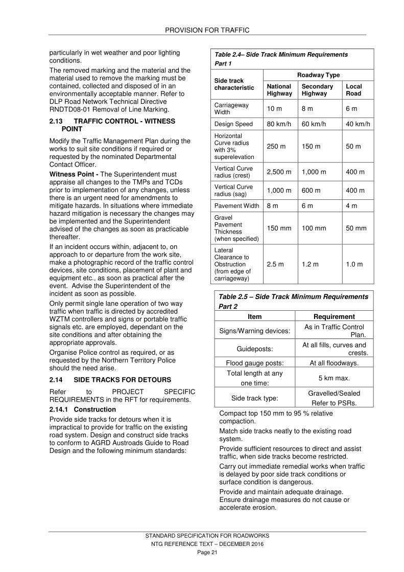
Table 2.4– Side Track Minimum Requirements
Part 1
Side track characteristic
Roadway Type
National Highway
Secondary Highway
Local Road
Carriageway Width
10 m 8 m 6 m
Design Speed 80 km/h 60 km/h 40 km/h
Horizontal Curve radius with 3% superelevation
250 m 150 m 50 m
Vertical Curve radius (crest)
2,500 m 1,000 m 400 m
Vertical Curve radius (sag)
1,000 m 600 m 400 m
Pavement Width 8 m 6 m 4 m
Gravel Pavement Thickness (when specified)
150 mm 100 mm 50 mm
Lateral Clearance to Obstruction (from edge of carriageway)
2.5 m 1.2 m 1.0 m
Table 2.5 – Side Track Minimum Requirements
Part 2
Item Requirement
Signs/Warning devices: As in Traffic Control
Plan.
Guideposts: At all fills, curves and
crests.
Flood gauge posts: At all floodways.
Total length at any
one time: 5 km max.
Side track type: Gravelled/Sealed
Refer to PSRs.
Compact top 150 mm to 95 % relative compaction.
Match side tracks neatly to the existing road system.
Provide sufficient resources to direct and assist traffic, when side tracks become restricted.
Carry out immediate remedial works when traffic is delayed by poor side track conditions or surface condition is dangerous.
Provide and maintain adequate drainage. Ensure drainage measures do not cause or accelerate erosion.

PROVISION FOR TRAFFIC
STANDARD SPECIFICATION FOR ROADWORKS
NTG REFERENCE TEXT – DECEMBER 2016
Page 22
Maintenance 2.14.2
Maintain the existing road network, and all side tracks, in use by the public.
Prevent dust nuisance by water spraying at regular intervals to keep surface moist.
Do not use waste oil as a dust suppressant.
Remove debris and rubbish.
Maintain road signs and guide posts in a clean state.
Table 2.6 – Side Track Maintenance Requirements
Surface type
Maintenance required
Sealed Surfaces:
Patch and repair all surfaces. Grade and roll shoulders.
Unsealed Surfaces:
Regrade and roll to maintain a comfortable riding quality at design speed.
ACCESS TO ADJACENT 2.15PROPERTIES AND SIDE ROADS
Maintain access to adjacent properties and side roads at all times to a level appropriate for the type and frequency of traffic.
Provide and erect proposed and approved signs detailing alternative access, only after approval from the Superintendent is obtained.
Ensure adequate access is maintained for pedestrians and cyclists as required, including delineated access if existing paths are being closed as part of the works.
TEMPORARY PEDESTRIAN ACCESS 2.16
Conform to: AS 1742.9 and AS 1742.10.
Maintain access for pedestrians, cyclists and persons with disabilities passing through and around the work site. Where existing paths are to be demolished or will become inaccessible or modified due construction works, provide temporary access to a standard not less than the pre-existing or pre-construction standard.
Temporary access must;
− Be clearly delineated and have adequate width and height clearance.
− Be smooth, free draining and free of obstructions and loose material.
− Provide clear guidance where paths change direction.
− Be illuminated by temporary lighting in urban areas to assist path users where existing street lighting has been removed or affected by the works.
− Be arranged so that path users are clearly visible to vehicle drivers and plant operators at road crossing points.
TEMPORARY BRIDGING – HOLD 2.17POINT
Design and construct any temporary bridging in accordance with the Austroads Guide to Bridge Technology.
Hold Point - Obtain written approval from the Regional Manager, Road Projects prior to commencement of any such works.
Ensure all environmental approvals have been obtained prior to the commencement of the works.
Hold Point - Provide copies of approvals obtained by Contractor to the Superintendent prior to the commencement of the works.
Provide and erect signage, fencing, road safety barriers and or guard railing etc. to prevent accidental access to the feature being bridged.
CONTRACTOR'S PLANT AND 2.18EQUIPMENT - HOLD POINT
Provide public traffic right of way at all times unless traffic control is in use.
Keep parking and materials storage clear of trafficked areas and clear zones in accordance with applicable AUSTROADS guides.
Do not leave equipment or tools unattended as a hazard to the public.
Hold Point - On roads carrying significant traffic, floodlight the road and area within 50 m of the site when working at night, if approved by the Superintendent, to a ground level luminance of 10 lux minimum.
Mobile Plant - Broadband Alarm 2.18.1
Standards
AS 4742: Machine-mounted forward and reverse audible warning alarm (withdrawn)
ISO 9533: Earth-moving machinery - Machine-mounted audible travel alarms and forward horns - Test methods and performance criteria
Definitions
Broadband alarm: Pulsed acoustic signal that comprises a range of frequencies and sometimes referred to as quacker, woosher, non-tonal reversing beepers or white sound.
Broadband/White-Sound Alarm Requirement:
Provide all construction vehicles and mobile plant fitted with Broadband Alarms (White Sound) before commencement of works.
Ensure that installation and proper operations of the alarm/warning system is sufficient before

PROVISION FOR TRAFFIC
STANDARD SPECIFICATION FOR ROADWORKS
NTG REFERENCE TEXT – DECEMBER 2016
Page 23
commencement of works including but not limited to:
- All alarms clearly audible above the noise level of the machinery or vehicle.
- Automatically activated when reverse gear is selected.
- Directional nature of the broadband alarm is appropriate for works.
Rotating Beacons on Plant 2.18.2
Provide beacons or other vehicle mounted warning devices on the highest point of the cabin roof or superstructure of all plant and equipment and in accordance with clause 3.12 ‘Vehicle mounted signs and devices’ of AS 1742.3 where these are being used within the road reserve. Fit beacons with globes rated at a minimum of 75 watts. Do not use strobe lights.
Ensure that the light is operational whenever the plant or equipment is working on, or within 9 metres of, the roadway.
Ensure that the light is visible from all approaches and not obscured by exhaust stacks, back hoe arms etc., or are covered in dust.
Protect the lights from damage by scrub etc.
ROAD WORK ZONE LENGTH 2.19
Conform to the requirements of AS 1742.3.
TRAFFIC SIGNAL AND COUNT 2.20STATIONS
Traffic Signals 2.20.1
Prior to commencement of the works and for the duration of the works clear the work and co-ordinate with the Department’s Traffic Section for the appropriate region.
This includes all works within the trafficked lanes;
− 150 m prior to the stop line
− 50 m past the stop line
− that affects the normal daily traffic flow at the intersection or for road reserve or median excavations greater than 150 mm
− within the area defined by the traffic signal poles and associated pits
− between the traffic signal poles and associated traffic signal control cabinet
Traffic Count Stations 2.20.2
Count Stations have in-pavement detection systems installed and cutting off or closing traffic lanes can have an impact on their operation.
Prior to the commencement of work within the trafficked lanes within 50 m of traffic signals or within 20 m of a count station controller, clear the work and co-ordinate for the duration of the
works with the Department’s Traffic Section for the appropriate region.
A map of count station locations is available from Department’s Transport Infrastructure Planning Division, contact 8924 7531, or from the Annual Traffic count reports at: https://transport.nt.gov.au/publications .
PORTABLE TRAFFIC SIGNALS 2.21
Use portable traffic signals conforming to the requirements of AS 1742.3 and AS 4191. Complete the portable traffic signal authorisation form (available from the Department’s Traffic section) to seek formal approval from the Superintendent to use the proposed portable traffic signals and the proposed time settings.
Portable traffic signals are for short-term traffic control applications only. Where traffic signal control is being proposed for periods greater than 2 months in a single location, consider the installation of temporary traffic signals.
For the area under the control of portable traffic signals, limit the lengths to no more than 1150 m. Use the time settings in the Time Settings clause as a guide for red time clearance and maximum green times. Frequently observe the prevailing traffic conditions and vehicle speeds and amend the times for the site as appropriate. Submit the changes to the Superintendent as soon as practicable thereafter.
Temporary Speed Limits – Hold Point 2.21.1
Impose a controlled area speed limit not exceeding 80 km/h if the portable traffic signals would otherwise be in a higher speed limit zone.
Hold Point - Work zone speed limits require approval from the Superintendent prior to implementation.
Sight Distance 2.21.2
Maintain a sight distance on the approach to portable traffic signals of not less than 150 metres. If this cannot be achieved, use appropriate advance warning signage to advise road users in advance of the sight line obstruction of the impending traffic signals ahead.
In cases where queuing traffic is extending past the advance warning signage, install further advance warning signs and speed zone signs further in advance, to prevent collisions at the end of the queue awaiting a green light. Avoid excessive traffic queuing by use of, and adjustment of, appropriate time settings on the portable traffic signals whenever possible.

PROVISION FOR TRAFFIC
STANDARD SPECIFICATION FOR ROADWORKS
NTG REFERENCE TEXT – DECEMBER 2016
Page 24
Time Settings 2.21.3
Table 2.7– General Time Settings
Mode All Red
Min. Green
Max. Green
Amber
Manual: M F M S
Fixed time:
S F S S
Vehicle Actuated:
S F S S
F: Fixed at 15 seconds.
M: Set the manual control switch each cycle.
S: Needs to be selected and preset by operator for each site.
Table 2.8 – Amber Time
Approach Speed Amber Time
Below 70 km/h
Above 70 km/h
4 seconds
5 seconds
RESTORATION 2.22
Upon completion of works:
− Remove all temporary warning signage and other traffic control devices.
− Remove all temporary works and reinstate the areas to their original state, including the removal and disposal of seal and dragging windrows and debris back across the side track carriageway.
− Stabilize all areas impacted by the works to prevent erosion.
− Where applicable reseed with local native grasses and trees and shrubs.
− Comply with the requirements of the Environmental Approvals and Clearances issued by DIPL and DENR, Environment Heritage and the Arts Division, Environmental Assessment and Policy Section, for the project.
− Reinstate permanent traffic control devices temporarily removed during the works.
Other Requirements 2.23
(If applicable) Refer to PROJECT SPECIFIC REQUIREMENTS in the Request for Tender.
Table 2.9 - Red and Green Times
All Red Period (Sec’s)
Max. Green Period (Sec’s)
Distance Between Stop Lines at traffic Signals (m) – Clearance speed 20 km/h
Distance Between Stop Lines at traffic Signals (m) – Clearance speed 40 km/h
2 30 0-30 0-50
5 35 34-45 50-90
10 35 45-75 90-150
15 40 75-105 150-210
20 40 105-135 210-270
25 45 135-165 270-330
30 45 165-195 330-390
40 50 195-250 390-500
50 50 250-310 500-620
60 60 310-365 620-730
70 70 365-415 730-830
80 80 415-465 830-930
90 90 465-525 930-1050
100 100 525-575 1050-1150
CLEARING, GRUBBING AND REHABILITATION
STANDARD SPECIFICATION FOR ROADWORKS
NTG REFERENCE TEXT – DECEMBER 2016
Page 25
3. CLEARING, GRUBBING AND REHABILITIATION
GENERAL 3.1
SPECIFICATION REFERENCE; Refer to the Standard Specification for Environmental Management and to the RFT.
BURNING; Do not light fires or burn any demolished material or vegetation either on or off the site.
CLEARING 3.2
DEMOLITION; Remove fencing, buildings, kerbing, debris, drainage structures, old road surfaces and other structures as required.
REMOVAL; Except for materials to be salvaged and retained by the Superintendent take possession of demolished materials and remove them from the site.
SALVAGED ITEMS; A list of items to be salvaged is included in PROJECT SPECIFIC REQUIREMENTS in the RFT
EXTENT; Clear the site only to the extent shown on the drawings and specified in this section.
ACCESS; Allow 3 metre wide cleared access ways around proposed culverts, gravel pits and stockpiles.
EXCESS CLEARING; Where excess clearing has taken place beyond that specified or shown on the drawings pay compensation for the damage and rehabilitate the areas in accordance with the Reinstatement clause.
COMPENSATION; Pay compensation (To be charged as a negative variation to the Contract) for excess clearing at the rate of $5 per square metre.
TREES TO BE RETAINED 3.3
Retain selected trees shown on the drawings or as directed.
PROTECTION; Protect from damage trees which are required to be retained. Do not remove topsoil from the areas within the dripline of the trees and keep the area free of construction equipment and materials.
DAMAGE; If a tree, which is marked to be retained, is damaged and repair work is considered impractical, or is attempted and fails, remove the tree and the root system, if so directed. Replace the tree with a tree of the same species and similar condition and size or pay compensation.
Compensation for damage to existing vegetation shall be borne by the Contractor as a negative variation to the Contract and determined as follows:
Tree valuation rate: $10 per cm. of tree circumference at a height 1 m above the ground.
Maximum valuation: $2500 per tree
Minimum valuation: $250 per tree
MULCHING 3.4
Mulch all cleared vegetative matter in mechanical brush chippers to a maximum size of 100 mm as the clearing work proceeds. Do not stockpile cleared material for later mulching.
STUMPS; Stumps and other material unsuitable for mulching may be buried in disused gravel pits during rehabilitation of the pits.
GRASSES; Do not mulch grass clods, roots or other components containing viable propagules. This material may be buried in disused gravel pits.
STOCKPILES; Stockpile mulched material on the site at a maximum height of 2 m for use during reinstatement work.
URBAN AREAS; Stockpile mulch on the site for reuse and deliver surplus mulch as directed by the Superintendent (within 10 km of the site) for use in local landscaping projects.
RURAL AREAS; Stockpile mulch on the site for reuse and power blow surplus mulch into the adjacent natural vegetated areas adjacent to the works.
STRIPPING OF TOP LAYER 3.5
EXTENT; Strip the top layer of natural material to a depth of 100 mm, for the full formation width.
Stockpile stripped material at sites within 1 km of the point of origin. Stockpile heights not to exceed 2.0 m.
Spread stripped material on areas to be landscaped and/or on road batters, following completion of earthworks.
TREATMENT OF EXISTING SEALED 3.6SURFACE
Rip the existing sealed surface.
Conform to the following:
Table 3.1– Treatment of Existing Sealed Surface
Specified Cover Over Existing Seal
Maximum Seal Fragment Size
Fill depth 500 mm or greater
1 m2.
Fill depth less than 500 mm
Remove seal from site.
Pavement resheeting only
Remove seal from site and replace with similar volume of pavement.

CLEARING, GRUBBING AND REHABILITATION
STANDARD SPECIFICATION FOR ROADWORKS
NTG REFERENCE TEXT – DECEMBER 2016
Page 26
SCARIFYING OF EXISTING ROADS 3.7
Remove seal from site. Alternatively, demolished seal may be buried in table drains if approved by the Superintendent. Provide 200 mm cover to buried material.
Scarify, both longitudinally and laterally, for the full width of the formation by ripping to a depth of 250 mm resulting in a maximum size of demolished seal of 100 mm.
Tyne spacing to be 500 mm maximum.
GRUBBING 3.8
Grub out and remove from the site all vegetation to a depth of 200 mm below subgrade surface in cut and 200 mm below natural surface under fills.
Fill grub holes and other excavations as required with standard fill material compacted to the density of the surrounding soil.
REINSTATEMENT 3.9
Reinstate any clearing undertaken during the contract to rehabilitate the area back consistent with its untouched surrounds. This includes seeding, planting, watering and other measures necessary to rehabilitate the area.
MULCH; Spread mulched material over the rehabilitated area, including batters and verges, to a uniform cover of 50 mm thickness.
DETOURS; Where detours are specified in PROVISION FOR TRAFFIC, or otherwise agreed to, rehabilitate the detour areas in accordance with the requirements of this section.
CLEANING UP 3.10
Remove all excess fill, rubble and other debris from the site. Dispose of the materials using a legal method.
OTHER REQUIREMENTS 3.11
(If applicable) Refer to PROJECT SPECIFIC REQUIREMENTS in the Request for Tender.
EARTHWORKS
STANDARD SPECIFICATION FOR ROADWORKS
NTG REFERENCE TEXT – DECEMBER 2016
Page 27
4. EARTHWORKS
STANDARDS 4.1
Conform to the following Standard and Publication unless specified otherwise:
AS 1289 (set) Methods of testing soils for engineering purposes.
NTMTM NT Materials Testing Manual. NTTM NT Test Methods
DEFINITIONS 4.2
CARRIAGEWAY:
That portion of a road for the use of vehicles including shoulders and auxiliary lanes.
FORMATION WIDTH:
Width of cut or fill including table drain(s), and out to the points of any batters.
OFFLET DRAIN:
Also described as a Table Drain Offlet. Provides relief at regular intervals of run off concentration in Table Drain. Drains water from Table Drain away from formation for dispersal into catchments.
SUBGRADE:
Top 150 mm of material below subgrade surface unless specified differently in RFT or on drawings.
SUBGRADE SURFACE:
The prepared surface immediately beneath the pavement and shoulder layers.
Also extends under footpaths, kerb and gutter, and surface structures.
SURFACE FORMATION:
The formation of a road from material generally cut from the table drains.
UNPAVED AREAS:
Those areas within the road reserve boundary which are not part of the road pavement, including any medians not paved, batters and table drains and blocks, but excluding footpaths and vehicle access strips.
UNSUITABLE MATERIAL
Any material that does not conform to the properties specified for the replacement materials to be used. If properties of the replacement materials to be used are not specified, then UNSUITABLE MATERIALS are materials which do not conform to the properties specified for standard fill.
EARTHWORKS IN CUT 4.3
Description 4.3.1
Operations necessary for excavation, irrespective of the type of material and subsurface conditions, including:
- working cuttings so that material meeting standard fill requirements is used for the subgrade;
- disposal of excess excavated material;
- compaction of material below the subgrade surface; and
- shaping and trimming of formation within cuttings.
Excess Material – Hold Point 4.3.2
Haul and dump and spread excess material:
− Not less than 125 metres from the new road centre line.
− To spoil dump sites specified. Clear site of organic material/topsoil prior to stockpiling material.
− Spread excess material and sheet with topsoil.
Refer to PROJECT SPECIFIC REQUIREMENTS in the RFT.
Dumped material remains the property of the Principal.
Ensure dumps will not dam surface water and streams or damage the works or other property.
Ensure dumping is not in streams.
Haul, dump and spread the materials in legally acceptable locations using legal methods.
Comply with AAPA clearances.
Comply with Environmental Management approvals, including within the road reserve.
Hold Point - Obtain approval from Superintendent prior to hauling, dumping and spreading excess material.
Rock in Subgrade – Hold Point 4.3.3
Hold point - Obtain agreement from the Superintendent to the extent of the excavation.
Excavate rock encountered in the subgrade.
Avoid forming pockets of shattered material below the level of the excavation.
Remove all loose material.
Trim the excavation to shed water.
Replace excavated material with select fill compacted to 95% relative compaction.
Unsuitable Material Below Subgrade 4.3.4Surface other than Rock – Hold Point
Hold point - Obtain directions from the Superintendent before works commence.
Excavate subgrade material which does not conform to the properties of standard fill as specified.
Dry out material with excessive moisture content to achieve a moisture content which permits specified compaction.
Replace excavated material with standard fill compacted to 95% relative compaction.

EARTHWORKS
STANDARD SPECIFICATION FOR ROADWORKS
NTG REFERENCE TEXT – DECEMBER 2016
Page 28
Floodways: Replace unsuitable material with material conforming with the following:
Angular or broken rock, free from organic matter and lumps of clay, complying with Table 4.1 – Grading - Suitable Fill Material Properties.
Table 4.1 – Grading - Suitable Fill Material Properties
Maximum size: 100 mm.
Plasticity Index: 10 maximum.
Linear Shrinkage 5.0 maximum.
AS Sieve (Mm) Percentage Passing
75.0 40 - 100
19.0 15 - 50
2.36 0 - 25
Blasting and Overbreak 4.3.5
Ensure blasting is not excessive. There will be no payment for overbreak beyond the limits of excavation specified.
Stability of Works, Rock Cuttings 4.3.6
Remove all loose material and rock which has been rendered unstable.
EARTHWORKS IN FILL 4.4
Description 4.4.1
Earthworks in fill includes winning, hauling, placing and compacting material on all prepared areas including holes, pits and other depressions.
Preparation Prior to Filling 4.4.2
Subsequent to stripping of topsoil, apply a minimum of three passes with maximum mass compaction equipment.
Benching 4.4.3
Cut a bench at the toe of the lower side batter when natural surface inclines at steeper than eight horizontal to one vertical.
Ensure the bench slopes downwards towards the centre line of the road and is 3 metres wide to provide a sound key for the toe of the fill.
Terrace the existing surface where side slopes are steeper than three horizontal to one vertical to provide a key for the fill.
Unsuitable Material Beneath Fill – Hold 4.4.4point
Hold point - Obtain directions from the Superintendent before works commence.
Remove unsuitable foundation material as directed before the fill is placed.
Replace excavated material with standard fill compacted to 95% relative compaction.
Construction Methods 4.4.5
Fill by either the "Compacted Layer", "Rocky Material" or "Rock Fill" method.
Mix to a homogeneous material before compacting.
Select appropriate method(s).
COMPACTED LAYER METHOD
Use where material generally does not contain cobbles, boulders or broken rock.
- Deposit and spread the material in uniform level layers to a maximum thickness of 250 mm loose measurement for the full width of fill.
- Compact each layer to the specified compaction (refer Table 5.12 – Dry Density Ratios for Conformance) before placing the next layer.
- Use standard fill for the subgrade.
ROCKY MATERIAL METHOD
Use where material contains some cobbles and boulders (maximum size 600 mm) with sufficient fines for the work to be free of voids.
- Break up rocks bridging between adjacent material to prevent cavities being formed.
- Maximum rock dimension: 600 mm or one-half the height of fill at the section where the rock is placed.
- Spread material in layers approximately equal to the maximum rock size.
- Work the rocky material in each layer until it is firm and unyielding.
- Construct to the bottom of the subgrade layer.
ROCKFILL METHOD
Use where material is predominantly cobbles or boulders with insufficient fines to fill voids.
- Place and work the material until interlock is achieved.
- Advance the fill by full width construction. Side dumping shall not be undertaken. The construction face shall be concave, with the shoulder face well in advance of the centre, except when filling in swamps or soft material when the advancing face ends shall be convex.
- Rock Dimensions.
Maximum vertical dimension: one-third of the height of fill being placed.
Maximum horizontal dimension: one-half of the height of the fill being placed.
- Construct to 300 mm below the bottom of the subgrade layer. Within 300 mm of the bottom of the subgrade layer use the Compacted Layer Method or Rocky Material Method, with a maximum particle size of 150 mm.

EARTHWORKS
STANDARD SPECIFICATION FOR ROADWORKS
NTG REFERENCE TEXT – DECEMBER 2016
Page 29
FILL MATERIAL 4.5
Fill material properties specified below are typical requirements. Refer to PROJECT SPECIFIC REQUIREMENTS in the RFT for any variations to these requirements.
General Fill 4.5.1
Use the best locally available material.
Use fill material, whether cut or borrow, that is free of organic matter and has a minimum soaked CBR at 95% MMDD of 20%, to AS 1289, and a plasticity index between 2% and 15%.
Standard Fill 4.5.2
Conform to the following properties:
Table 4.2 – Standard Fill Properties
CBR 4 day soaked at 95% MMDD to AS 1289:
Minimum 20
Maximum Particle Size: 100mm
Plasticity Index: 2%-15%
Select Fill 4.5.3
Select fill shall be comprised of gravel, decomposed rock or broken rock, free from organic matter and lumps of clay.
Conform to the following Grading and Properties:
Table 4.3 – Grading – Select Fill
AS Sieve (mm) % Passing
(Dry Weight)
75.00 100
9.50 30 - 100
2.36 15 - 65
0.075 5 - 25
Table 4.4 – Select Fill Properties
CBR, 4 day soaked at 95% MMDD to AS 1289:
30 minimum.
Plasticity Index: 2 - 15% maximum.
Linear Shrinkage: 2 - 6%.
Sand Clay Fill 4.5.4
Sand clay (clayey sand) may be used as an alternative to Select Fill.
Conform to the following Properties and Grading:
Table 4.5 – Sand Clay Fill Properties
CBR: 4 day soaked and 95% MMDD to AS 1289:
30 minimum
Plasticity Index 15% maximum
Linear Shrinkage 1 - 8%
Table 4.6 – Grading – Sand Clay Fill
As Sieve (Mm) % Passing (Dry
Weight)
4.75 80 - 100
2.36 60 - 100
0.425 30 - 60
0.075 14 - 28
PREPARATION AND MAINTENANCE 4.6OF SUBGRADE SURFACE
Trim surface to the compliance tolerances specified free of depressions and free draining.
Maintain and repair any damage to the prepared surface prior to placing further material.
EARTHWORKS FOR DRAINAGE 4.7
Comply with the requirements of the Standard Specification for Environmental Management.
Stream Diversions 4.7.1
Excavate stream diversions as shown on the drawings.
Fill existing watercourses as shown on the drawings.
Divert streams temporarily where it is necessary for the construction of the work.
Ensure that existing waterways are not filled, altered, or diverted except where specified.
Levees 4.7.2
Construct using standard fill with a Plasticity Index of;
- 6% minimum for areas north of a line connecting Birrindudu – Dunmarra – Wollogorang.
- 3% minimum for areas on or south of a line connecting Birrindudu – Dunmarra - Wollogorang
Compact in layers not exceeding 150 mm compacted thickness.
Construct in locations, and to dimensions shown on the drawings.
Table Drains 4.7.3
Construct to the dimensions shown on the drawings.
Grade to prevent ponding of water.
Discharge into culverts, offlet drains or watercourses.
Table Drain Offlets 4.7.4
Divert table drains into offlet drains at intervals not exceeding 150 m or as otherwise specified in PROJECT SPECIFIC REQUIREMENTS in the RFT.
EARTHWORKS
STANDARD SPECIFICATION FOR ROADWORKS
NTG REFERENCE TEXT – DECEMBER 2016
Page 30
Ensure the capacity of the offlet is not less than the capacity of the table drain, and is of similar cross section.
Align and grade offlet so that the water drains away without scour and damage to disperse as sheet flow or into natural watercourses.
Table Drain Blocks 4.7.5
Block table drains at offlets.
Construct blocks from standard fill conforming to the following requirements:
Plasticity Index:
- 6% minimum for areas north of a line connecting Birrindudu – Dunmarra – Wollogorang.
- 3% minimum for areas on or south of a line connecting Birrindudu – Dunmarra - Wollogorang
Length: To extend from edge of shoulder to top of outer table drain batter.
Width: 3 metre minimum measured parallel to the road centre line.
Height: To edge of shoulders.
Compaction: Layers not exceeding 150 mm compacted thickness.
Catch Drains 4.7.6
Construct catch drains prior to earthworks in cut.
Depth: 500 mm (minimum) into solid ground.
Gradients: Ensure free flow, prevent ponding of water, prevent scour.
Outlets: As terrain permits construct at frequent intervals to reduce scour. Construct a block on continuous grades to divert water into culverts or drains.
Offset: 2 m (minimum) and 4 m (maximum) beyond the edge of the cutting.
Divert the drain neatly around large rocks and trees.
WIDENING OF EXISTING FORMATION 4.8
Cut back the existing formation and pavement as shown on the drawings by not less than 150 mm on each edge to sound densely compacted material to form a uniform edge (curved or straight where applicable).
Construct the widening by cutting and filling as specified.
TRIM AND COMPACT UNPAVED 4.9AREAS
Shape, grade and compact as specified.
See Table 5.6.2 - Test Frequencies for Soils - Part 3 of 3.
SURFACE FORMATION 4.10
General 4.10.1
Form the road generally with material cut from the table drains, in accordance with the typical cross section.
Mix to a homogeneous material before compacting.
Allow for construction to the specified height above natural surface, either by local widening of table drains or importation of standard fill.
Pastoral Access Roads 4.10.2
For in situ pavement materials comply with the following:
CBR 4 day soaked at 95% MMDD to AS 1289: 30 minimum.
Maximum particle size: 37.5 mm.
Plasticity Index: 4 - 12%.
Alternatively sheet the in situ material with 150 mm imported material complying with the above, compacted to 95% relative compaction.
BATTER PROTECTION BY GRASSING 4.11
Fill batters to have a surface layer 100 mm minimum thickness of stripped material, which is additional to the specified cross section.
Grassing 4.11.1
Refer to PROJECT SPECIFIC REQUIREMENTS in the RFT for extent of batters to be treated.
Seed Mixture and Fertiliser 4.11.2
Provide certified seed complying with the requirements in the LANDSCAPE Section.
Fertiliser to comply with Table 16.3 - Fertilisers in LANDSCAPE.
Refer to PROJECT SPECIFIC REQUIREMENTS in the RFT for application rate.
Grass Seed Application Technique 4.11.3
Conform to the LANDSCAPE Section.
Fabric protection to be used for all slopes steeper than 3:1. Fabric protection may consist of using jute mesh or equivalent in conjunction with hydromulching or the use of matting.
Smooth batters.
Form drains to control stormwater and prevent erosion until batter is grassed.
Place "top layer" soil from clearing operations over the batters to a depth of 50 mm.
Apply seed mixture, fertiliser, and protection. Establish grass and keep damp by watering until flowering stage is reached.

EARTHWORKS
STANDARD SPECIFICATION FOR ROADWORKS
NTG REFERENCE TEXT – DECEMBER 2016
Page 31
Repair any erosion.
Reseed areas until establishment is achieved.
Acceptance 4.11.4
The minimum quality of grassing required for acceptance is;
- Establishment shall be uniform.
- Coverage rate: 98% minimum of total area.
BRIDGE FOUNDATIONS 4.12
Conditions 4.12.1
The data shown on the drawings as to the character and depths of the various strata are approximate only, and no warranty, expressed or implied, is given by the Principal that the same or similar materials will be encountered during the progress of work.
Tenderers are advised to inspect copies of the bore logs and the original core samples.
Superintendent will advise where original samples are available for inspection.
Excavation – Hold point 4.12.2
GENERAL
The extent of foundations is specified by dimension and reduced level.
Excavate to the required lines and levels.
Dispose of excess material in accordance with clause 4.3.2 Excess Material – Hold Point in 4.3 Earthworks In Cut.
PREPARATION
Inspect and record the condition of all structures and services in the adjacent area prior to using pile drivers.
Hold point - Obtain Superintendent’s agreement with inspection record of current conditions.
Cut foundation to a firm surface either stepped or roughened, as directed.
Remove loose material.
Hold point - Obtain the Superintendent’s approval for the foundation surface before placing the blinding concrete.
Place a 50 mm thick layer of blinding concrete.
COFFER-DAMS SHORING AND SHEETING
Design any coffer-dams required for the execution of the works.
Construct coffer-dams to adequate height and depth and as waterproof as necessary for proper performance.
Provide adequate clearance for:
- construction of forms;
- inspection of interiors; and
- pumping from outside the forms.
Remove shoring and sheeting from inside the excavation.
Remove coffer-dams, sheeting and the like from the site when no longer required.
Do not damage the finished structure or disturb adjacent in situ material.
Remove obstructions from waterways.
Backfilling 4.12.3
Backfill the excavation up to natural surface level with excavated material or select fill.
The excavated material may be used for backfill provided it is free of wood, other organic and other extraneous or deleterious material.
Mix to a homogeneous material before compacting.
Place in horizontal layers not exceeding 150 mm compacted thickness.
Compact to the density ratio specified in Table 5.12 – Dry Density Ratios for Conformance in CONFORMANCE TESTING.
Compact using equipment that will not damage the bridge substructure.
FILL ADJACENT TO BRIDGE 4.13STRUCTURES
GENERAL
Fill includes preparation of the fill area, supply, placing and compacting fill, drainage layers and piping, disposal of unsuitable material and trimming and protection of batters.
Place select fill against structures after 14 days from date of casting or after test results confirm 70% of characteristic concrete strength achieved.
Avoid unbalanced loading on structures.
Do not operate mechanically driven vibrating rollers exceeding 1 tonne within 3 metres of the structures.
ABUTMENTS AND WINGWALLS
Prepare the area as specified.
Compact select fill in horizontal layers not exceeding 150 mm compacted thickness in areas adjacent to abutments and wing walls extending horizontally a distance equal to two times the height of the adjacent structure, or as specified.
Prevent water from ponding behind abutments and wing walls.
Provide weep holes and drain pipes as specified.
COMPACTION 4.14
Mix to a homogeneous material and compact with no compaction planes and free of cracking to conform to the Dry Density Ratios specified in Table 5.12 – Dry Density Ratios for Conformance in CONFORMANCE TESTING and to 4.15 Conformance.

EARTHWORKS
STANDARD SPECIFICATION FOR ROADWORKS
NTG REFERENCE TEXT – DECEMBER 2016
Page 32
CONFORMANCE 4.15
Existing Surface Levels – Witness 4.15.1Point
Witness point - Obtain inspections of any disputed existing surface levels with the Superintendent prior to any stripping or earthworks operations.
Quantities are based on the existing surface levels prior to the stripping of the top layer.
Allow for suitable material to replace the stripped layer (Cut and Fill) in the items for EARTHWORKS.
Tolerances 4.15.2
Finish earthworks to a smooth compacted and uniform surface within the following limits:
Formation Width: Not less than specified.
Subgrade Surface: Maximum 25 mm below and not above specified level.
Subgrade Width: Not less than specified. Extend 150 mm minimum beyond the back of kerb.
Batter: Not steeper than the specified slope.
Maximum variation at any point from specified plane of batter shall be 150 mm in earth and 300 mm in rock.
Unpaved Areas/ Table Drain Invert:
Maximum 75 mm above or below specified level free of depressions capable of ponding water. Maximum 40 mm adjacent to kerbs.
Proof Rolling – Witness Point – Hold 4.15.3point
Proof roll all areas and obtain satisfactory results before ordering conformance testing of those areas.
Hold point - Submit a proof rolling procedure to the Superintendent for approval including the proposed method of preparing the areas and the extent of proof rolling.
Witness point - Give the Superintendent not less than 24 hours notice of the location and commencement time for the proof rolling.
Plant Requirements; use plant in proof rolling procedures that comply with the following requirements:
Static smooth wheeled rollers with a mass of not less than 12 tonnes and a load intensity under either the front or rear wheels of not less than 6 tonnes per metre width of wheel. Pneumatic tyred plant with a mass of not less than 20 tonnes and with a ground contact pressure under either the front or rear wheels of not less
than 450 kPa per tyre and a ground contact area of not less than .035 sq.m. per tyre.
Check areas for level tolerance and layer thickness before proof rolling.
Proof roll each layer immediately following completion of compaction. If proof rolling is carried out at a later time, water the surface and roll with the test roller prior to commencement of proof rolling.
Compliance; the proof rolling requirements are deemed to comply when an area withstands proof rolling without visible deformation or springing.
Remedial work; remove and reconstruct areas that deform or break up.
Conformance Testing – Hold point 4.15.4
Ordering procedures; refer to CONFORMANCE TESTING for testing requirements and test ordering procedures.
General Fill
Conformance testing will be carried out on each layer of fill.
Subgrade
Subgrade surface will be tested only when it is within level tolerance and conforms to proof rolling.
Check subgrade surface levels prior to testing.
Hold point – Obtain the Superintendent’s approval of subgrade conformance prior to placing further material.
OTHER REQUIREMENTS 4.16
Refer to PROJECT SPECIFIC REQUIREMENTS in the RFT.
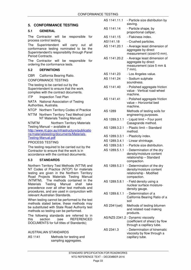
CONFORMANCE TESTING
STANDARD SPECIFICATION FOR ROADWORKS
NTG REFERENCE TEXT – DECEMBER 2016
Page 33
5. CONFORMANCE TESTING
GENERAL 5.1
The Contractor will be responsible for process control testing.
The Superintendent will carry out all conformance testing nominated to be the Superintendent's responsibility through Panel Period Contracts.
The Contractor will be responsible for ordering the conformance tests.
DEFINITIONS 5.2
CBR California Bearing Ratio.
CONFORMANCE TESTING
The testing to be carried out by the Superintendent to ensure that the work complies with the contract documents.
ITP Inspection Test Plan
NATA National Association of Testing Authorities, Australia.
NTCP Northern Territory Codes of Practice
NTTM Northern Territory Test Method (and NT Materials Testing Manual)
NTMTM Northern Territory Materials Testing Manual – available at http://www.nt.gov.au/infrastructure/publications/materialstesting/documents/Materials-Testing-Manual.pdf
PROCESS TESTING
The testing required to be carried out by the Contractor to ensure that the work is in accordance with the contract documents.
STANDARDS 5.3
Northern Territory Test Methods (NTTM) and NT Codes of Practice (NTCP) for materials testing are given in the Northern Territory Road Projects Materials Testing Manual (NTMTM). The methods contained in the Materials Testing Manual shall take precedence over all other test methods and procedures, and are used in conjunction with relevant Australian Standards.
When testing cannot be performed to the test methods stated below, these methods may be substituted with State Road Authority test methods so testing can be performed.
The following standards are referred to in this section (see REFERENCED DOCUMENTS for full titles of Standards);
AUSTRALIAN STANDARDS
AS 1141 Methods for testing and sampling aggregates.
AS 1141.11.1 - Particle size distribution by sieving.
AS 1141.14 - Particle shape, by proportional calliper.
AS 1141.15 - Flakiness index.
AS1141.18 - Crushed particles.
AS 1141.20.1 - Average least dimension of aggregate by direct measurement (size≥10 mm).
AS 1141.20.2 - Average least dimension of aggregate by direct measurement (size 5 mm & 7 mm).
AS 1141.23 - Los Angeles value.
AS 1141.24 - Sodium sulphate soundness.
AS 1141.40 - Polished aggregate friction value - Vertical road-wheel machine.
AS 1141.41 - Polished aggregate friction value – Horizontal bed machine.
AS 1289 Methods of testing soils for engineering purposes.
AS 1289.3.1.1 - Liquid limit – Four point Casagrande method.
AS 1289.3.2.1 - Plastic limit – Standard method.
AS 1289.3.3.1 - Plasticity index.
AS 1289.3.4.1 - Linear shrinkage.
AS 1289.3.6.1 - Particle size distribution.
AS 1289.5.1.1 - Determination of the dry density/moisture content relationship – Standard compaction.
AS 1289.5.2.1 - Determination of the dry density/moisture content relationship - Modified compaction.
AS 1289.5.8.1 - Field density using a nuclear surface moisture-density gauge.
AS 1289.6.1.1 - Determination of a California Bearing Ratio of a soil
AS 2341(set) Methods of testing bitumen and related road making products.
AS/NZS 2341.2 - Dynamic viscosity (coefficient of shear) by flow through a capillary tube.
AS 2341.3 - Determination of kinematic viscosity by flow through a capillary tube.
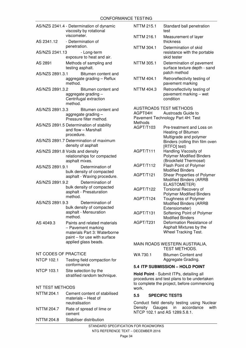
CONFORMANCE TESTING
STANDARD SPECIFICATION FOR ROADWORKS
NTG REFERENCE TEXT – DECEMBER 2016
Page 34
AS/NZS 2341.4 - Determination of dynamic viscosity by rotational viscometer.
AS 2341.12 - Determination of penetration.
AS/NZS 2341.13 - Long-term exposure to heat and air.
AS 2891 Methods of sampling and testing asphalt.
AS/NZS 2891.3.1 Bitumen content and aggregate grading – Reflux method.
AS/NZS 2891.3.2 Bitumen content and aggregate grading – Centrifugal extraction method.
AS/NZS 2891.3.3 Bitumen content and aggregate grading – Pressure filter method.
AS/NZS 2891.5 Determination of stability and flow – Marshall procedure.
AS/NZS 2891.7 Determination of maximum density of asphalt
AS/NZS 2891.8 Voids and density relationships for compacted asphalt mixes.
AS/NZS 2891.9.1 Determination of bulk density of compacted asphalt - Waxing procedure.
AS/NZS 2891.9.2 Determination of bulk density of compacted asphalt - Presaturation method.
AS/NZS 2891.9.3 Determination of bulk density of compacted asphalt - Mensuration method.
AS 4049.3 Paints and related materials – Pavement marking materials Part 3: Waterborne paint – for use with surface applied glass beads.
NT CODES OF PRACTICE
NTCP 102.1 Testing field compaction for conformance
NTCP 103.1 Site selection by the stratified random technique.
NT TEST METHODS
NTTM 204.1 Cement content of stabilised materials – Heat of neutralisation
NTTM 204.7 Rate of spread of lime or cement
NTTM 204.8 Stabiliser distribution
NTTM 215.1 Standard ball penetration test
NTTM 216.1 Measurement of layer thickness
NTTM 304.1 Determination of skid resistance with the portable skid tester
NTTM 305.1 Determination of pavement surface texture depth - sand patch method
NTTM 404.1 Retroreflectivity testing of pavement marking
NTTM 404.3 Retroreflectivity testing of pavement marking – wet condition
AUSTROADS TEST METHODS AGPT04H Austroads Guide to Pavement Technology Part 4H: Test Methods AGPT/T103 Pre-treatment and Loss on
Heating of Bitumen Multigrade and polymer Binders (rolling thin film oven [RTFO] test)
AGPT/T111 Handling Viscosity of Polymer Modified Binders (Brookfield Thermosel)
AGPT/T112 Flash Point of Polymer Modified Binders
AGPT/T121 Shear Properties of Polymer Modified Binders (ARRB ELASTOMETER)
AGPT/T122 Torsional Recovery of Polymer Modified Binders
AGPT/T124 Toughness of Polymer Modified Binders (ARRB Extensiometer)
AGPT/T131 Softening Point of Polymer Modified Binders
AGPT/T231 Deformation Resistance of Asphalt Mixtures by the Wheel Tracking Test.
MAIN ROADS WESTERN AUSTRALIA, TEST METHODS.
WA 730.1 Bitumen Content and Aggregate Grading.
ITP SUBMISSION – HOLD POINT 5.4
Hold Point - Submit ITPs, detailing all procedures and test plans to be undertaken to complete the project, before commencing work.
SPECIFIC TESTS 5.5
Conduct field density testing using Nuclear Density Gauges in accordance with NTCP 102.1 and AS 1289.5.8.1.

CONFORMANCE TESTING
STANDARD SPECIFICATION FOR ROADWORKS
NTG REFERENCE TEXT – DECEMBER 2016
Page 35
Conduct CBR moulding using a compaction hammer conforming with the requirements of AS 1289.5.1.1 or AS 1289.5.2.1.
Where tests are required that are not included in the manual use the appropriate Australian Standard.
PANEL PERIOD CONTRACTORS 5.6
The Principal has in place Panel Period Contracts with NATA accredited testing companies. The Superintendent will provide a list of the Panel Period Contractors to be used for conformance testing on this contract when the contract is awarded. The Superintendent reserves the right to use other NATA accredited laboratories when panel contractors are unable to carry out specific tests.
ORDERING TESTING 5.7
When required, in accordance with the contract documents, order the conformance testing in writing directly from the Panel Period Contractors. Order all testing using the Department’s Test Request Form. Include on the order the following information:
- Lot boundaries including start and finish chainages, length and width
- Type of layer
- Type of tests required
- Date and time when lot will be ready for testing
Start with the first Contractor on the list and rotate in sequence for each set of tests. Do not bypass any Panel Period Contractor on the list unless that Panel Period Contractor provides a written explanation that he is unable to carry out the required testing to the time frames listed in the Table “Testing and Reporting Completion Times”. In this instance, the written explanation must be provided to the Superintendent at the same time as the order for testing. Panel Period Contractors that are unable to carry out the required testing will be placed at the end of the rotation sequence.
Conformance Testing 5.7.1
The Superintendent will pay for all conformance testing directly to the Panel Period Contractor selected to perform the conformance tests required under this contract and nominated as the Superintendent’s responsibility.
If any tests fail to meet specification, all retesting costs will be a negative variation to
the contract. Failures in bitumen tests refer to Superintendent.
When testing has been ordered and the site is not ready for testing at the time specified by the Contractor, the Contractor will bear the cost of time and travel incurred by the Panel Period Contractor and the Superintendent, where applicable.
Process Testing 5.7.2
The Contractor is responsible for the ordering up and payment for all process tests carried out.
NOTICE OF TESTING – WITNESS 5.8POINT
Give the Panel Period Contractor written notice in advance of each stage of the works requiring conformance testing, including re-testing.
Witness point - Provide the Superintendent with a copy of the order for testing simultaneously with the order being sent to the Panel Period Contractor.
Any communication with the Panel Period Contractors, other than the ordering of testing or inquiring on the timing of test results, must be forwarded through the Superintendent.
Provide the Superintendent with the results of process control testing as identified in the relevant ITP with all requests for conformance testing.
Witness point - Notify the Superintendent prior to any rework of failed lots.
TABLES - TEST FREQUENCIES, 5.9COMPLIANCE TESTING
Test frequencies as per tables;
Table 5.1 – Test Frequencies for Bitumen Spray Sealing Table 5.2 – Asphalt Testing Frequencies - During Works Table 5.3 – Asphalt Testing Frequencies – After Works Completion Table 5.4 – Number of Cores per Lot Table 5.5 - Test Frequencies For Soils – Part 1 of Table 5.6 - Test Frequencies For Soils – Part 2 of Table 5.6.2 - Test Frequencies For Soils - Part 3 of 3 Table 5.7 - Test Frequencies for Aggregates and Pavement Surfaces, Table 5.8 - Sampling Frequencies For Fresh Concrete and Table 5.9 - MMDD Curing Times
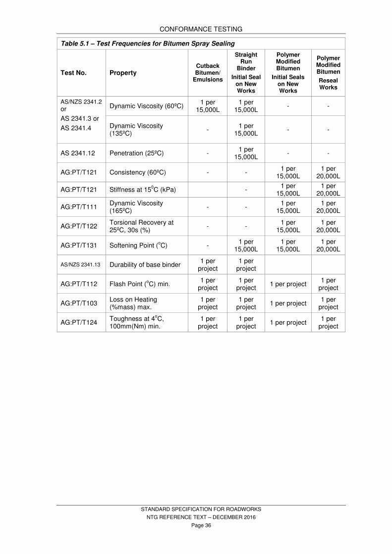
CONFORMANCE TESTING
STANDARD SPECIFICATION FOR ROADWORKS
NTG REFERENCE TEXT – DECEMBER 2016
Page 36
Table 5.1 – Test Frequencies for Bitumen Spray Sealing
Test No. Property Cutback Bitumen/
Emulsions
Straight Run
Binder
Initial Seal on New Works
Polymer Modified Bitumen
Initial Seals on New Works
Polymer Modified Bitumen
Reseal Works
AS/NZS 2341.2 or
AS 2341.3 or
AS 2341.4
Dynamic Viscosity (60ºC) 1 per
15,000L 1 per
15,000L - -
Dynamic Viscosity (135ºC)
- 1 per
15,000L - -
AS 2341.12 Penetration (25ºC) - 1 per
15,000L - -
AG:PT/T121 Consistency (60ºC) - - 1 per
15,000L 1 per
20,000L
AG:PT/T121 Stiffness at 150C (kPa) -
1 per 15,000L
1 per 20,000L
AG:PT/T111 Dynamic Viscosity (165ºC)
- - 1 per
15,000L 1 per
20,000L
AG:PT/T122 Torsional Recovery at 25ºC, 30s (%)
- - 1 per
15,000L 1 per
20,000L
AG:PT/T131 Softening Point (oC) -
1 per 15,000L
1 per 15,000L
1 per 20,000L
AS/NZS 2341.13 Durability of base binder 1 per
project 1 per
project
AG:PT/T112 Flash Point (oC) min.
1 per project
1 per project
1 per project 1 per
project
AG:PT/T103 Loss on Heating (%mass) max.
1 per project
1 per project
1 per project 1 per
project
AG:PT/T124 Toughness at 4
oC,
100mm(Nm) min. 1 per
project 1 per
project 1 per project
1 per project
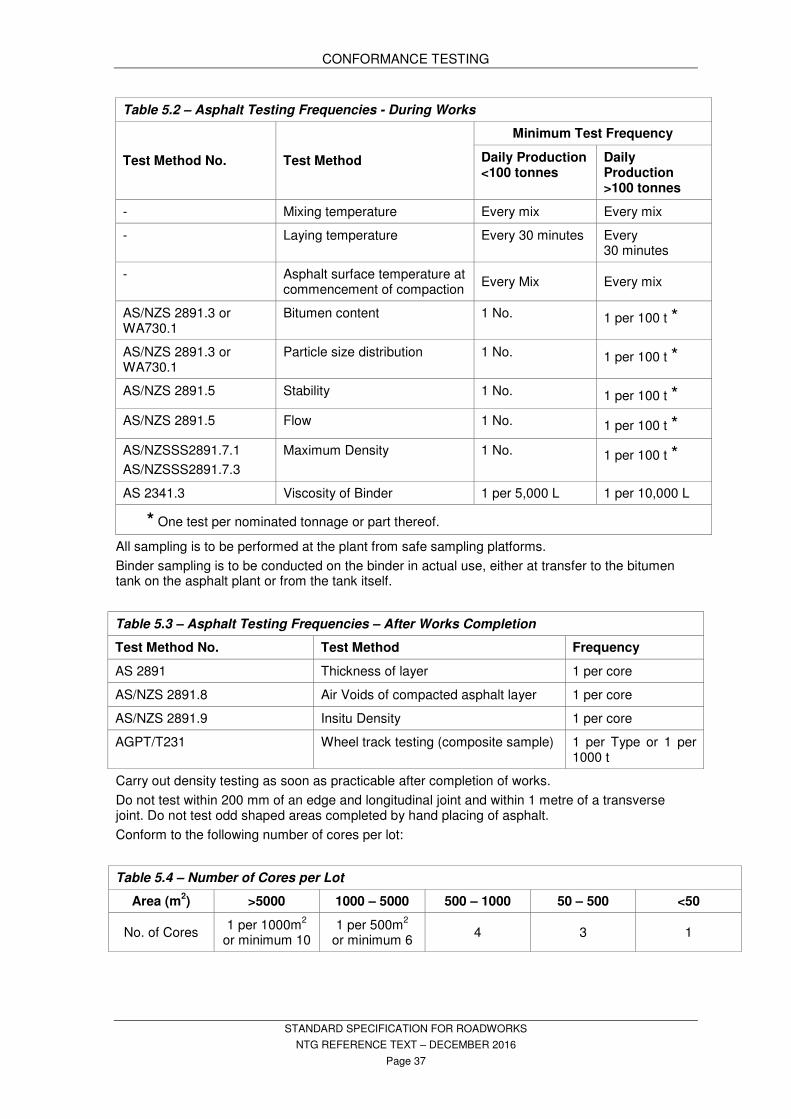
CONFORMANCE TESTING
STANDARD SPECIFICATION FOR ROADWORKS
NTG REFERENCE TEXT – DECEMBER 2016
Page 37
Table 5.2 – Asphalt Testing Frequencies - During Works
Test Method No. Test Method
Minimum Test Frequency
Daily Production <100 tonnes
Daily Production >100 tonnes
- Mixing temperature Every mix Every mix
- Laying temperature Every 30 minutes Every 30 minutes
- Asphalt surface temperature at commencement of compaction
Every Mix Every mix
AS/NZS 2891.3 or WA730.1
Bitumen content 1 No. 1 per 100 t *
AS/NZS 2891.3 or WA730.1
Particle size distribution 1 No. 1 per 100 t *
AS/NZS 2891.5 Stability 1 No. 1 per 100 t *
AS/NZS 2891.5 Flow 1 No. 1 per 100 t *
AS/NZSSS2891.7.1
AS/NZSSS2891.7.3
Maximum Density 1 No. 1 per 100 t *
AS 2341.3 Viscosity of Binder 1 per 5,000 L 1 per 10,000 L
* One test per nominated tonnage or part thereof.
All sampling is to be performed at the plant from safe sampling platforms.
Binder sampling is to be conducted on the binder in actual use, either at transfer to the bitumen tank on the asphalt plant or from the tank itself.
Table 5.3 – Asphalt Testing Frequencies – After Works Completion
Test Method No. Test Method Frequency
AS 2891 Thickness of layer 1 per core
AS/NZS 2891.8 Air Voids of compacted asphalt layer 1 per core
AS/NZS 2891.9 Insitu Density 1 per core
AGPT/T231 Wheel track testing (composite sample) 1 per Type or 1 per 1000 t
Carry out density testing as soon as practicable after completion of works.
Do not test within 200 mm of an edge and longitudinal joint and within 1 metre of a transverse joint. Do not test odd shaped areas completed by hand placing of asphalt.
Conform to the following number of cores per lot:
Table 5.4 – Number of Cores per Lot
Area (m2) >5000 1000 – 5000 500 – 1000 50 – 500 <50
No. of Cores 1 per 1000m
2
or minimum 10 1 per 500m
2
or minimum 6 4 3 1
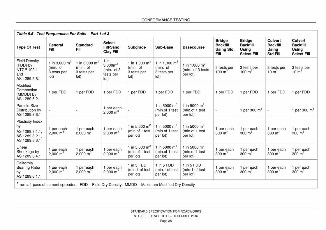
CONFORMANCE TESTING
STANDARD SPECIFICATION FOR ROADWORKS
NTG REFERENCE TEXT – DECEMBER 2016
Page 38
Table 5.5 - Test Frequencies For Soils – Part 1 of 3
Type Of Test General Fill
Standard Fill
Select Fill/Sand Clay Fill
Subgrade Sub-Base Basecourse
Bridge Backfill Using Std. Fill
Bridge Backfill Using Select Fill
Culvert Backfill Using Std.Fill
Culvert Backfill Using Select Fill
Field Density (FDD) by NTCP 102.1 and AS 1289.5.8.1
1 in 3,000 m2
(min. of 3 tests per lot)
1 in 3,000 m2
(min. of 3 tests per lot)
1 in 3,000m
2
(min. of 3 tests per lot)
1 in 1,000 m2
(min. of 3 tests per lot)
1 in 1,000 m2
(min. of 3 tests per lot)
1 in 1,000 m2
(min. of 3 tests per lot)
3 tests per 100 m
3
3 tests per 100 m
3
3 tests per 10 m
3
3 tests per 10 m
3
Modified Compaction (MMDD) by AS 1289.5.2.1
1 per FDD 1 per FDD 1 per FDD 1 per FDD 1 per FDD 1 per FDD 1 per FDD 1 per FDD 1 per FDD 1 per FDD
Particle Size Distribution by AS 1289.3.6.1
- - 1 per each 2,000 m
3
- 1 in 5000 m
2
(min.of 1 test per lot)
1 in 5000 m2
(min.of 1 test per lot)
- 1 per 300 m3 - 1 per 300 m
3
Plasticity Index by
AS 1289.3.1.1, AS 1289.3.2.1, AS 1289.3.3.1
1 per each 2,000 m
3
1 per each 2,000 m
3
1 per each 2,000 m
3
1 in 5,000 m2
(min.of 1 test per lot)
1 in 5000 m2
(min.of 1 test per lot)
1 in 5000 m2
(min.of 1 test per lot)
1 per each 300 m
3
1 per each 300 m
3
1 per each 300 m
3
1 per each 300 m
3
Linear Shrinkage by AS 1289.3.4.1
1 per each 2,000 m
3
1 per each 2,000 m
3
1 per each 2,000 m
3
1 in 5,000 m2
(min.of 1 test per lot)
1 in 5000 m2
(min.of 1 test per lot)
1 in 5000 m2
(min.of 1 test per lot)
1 per each 300 m
3
1 per each 300 m
3
1 per each 300 m
3
1 per each 300 m
3
California Bearing Ratio by AS 1289.6.1.1
1 per each 2,000 m
3
1 per each 2,000 m
3
1 per each 2,000 m
3
1 in 5 FDD (min.1 of test per lot)
1 in 5 FDD (min.1 of test per lot)
1 in 5 FDD (min.1 of test per lot)
1 per each 300 m
3
1 per each 300 m
3
1 per each 300 m
3
1 per each 300 m
3
* run = 1 pass of cement spreader; FDD – Field Dry Density; MMDD – Maximum Modified Dry Density

CONFORMANCE TESTING
STANDARD SPECIFICATION FOR ROADWORKS
NTG REFERENCE TEXT – DECEMBER 2016
Page 39
Table 5.6 - Test Frequencies For Soils – Part 2 of 3
Type Of Test Subgrade Sub-Base Basecourse
Pavement Layer Thickness by NTTM 216.1 - 1 per FDD 1 per FDD
Ball Embedment by NTTM 215.1 - - 1 in 5,000 m2
Pavement Degree of Saturation
prior to Sealing by AS 1289
- - 1 in 5,000 m2
Stabiliser Spread Rate by NTTM 204.7 1 per run * 1 per run 1 per run
Stabiliser Content by NTTM 204.1 1 per 1000m2 with a min. of 3
tests 1 per 1000m
2 with a min. of 3
tests 1 per 1000m
2 with a min. of 3 tests
Stabiliser Distribution by NTTM 204.8 1 per 1000m2 with a min. of 3
tests 1 per 1000m
2 with a min. of 3
tests 1 per 1000m
2 with a min. of 3 tests
Soluble Salt Content of Construct. Water - - 1 per water source
* run = 1 pass of cement spreader; FDD – Field Dry Density; MMDD – Maximum Modified Dry Density
Table 5.6.2 - Test Frequencies for Soils - Part 3 of 3
Type of Test Unpaved areas (including unpaved medians, batters, table drains and blocks)
Field Density (FDD) by NTCP 102.1 and AS 1289.5.8.1
1 for every 100 lineal metres or part thereof
Modified Compaction (MMDD) by AS 1289.5.2.1
1 per each 3 FDD tests
Plasticity Index by AS 1289.3.1.1, AS 1289.3.2.1, AS 1289.3.3.1
For Table Drain blocks only - 1 per each 3 blocks
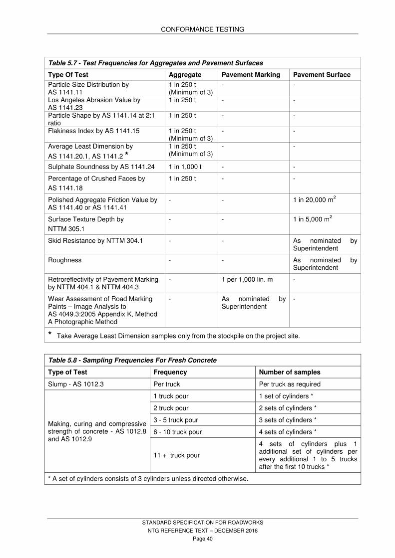
CONFORMANCE TESTING
STANDARD SPECIFICATION FOR ROADWORKS
NTG REFERENCE TEXT – DECEMBER 2016
Page 40
Table 5.7 - Test Frequencies for Aggregates and Pavement Surfaces
Type Of Test Aggregate Pavement Marking Pavement Surface
Particle Size Distribution by AS 1141.11
1 in 250 t (Minimum of 3)
- -
Los Angeles Abrasion Value by AS 1141.23
1 in 250 t - -
Particle Shape by AS 1141.14 at 2:1 ratio
1 in 250 t - -
Flakiness Index by AS 1141.15 1 in 250 t (Minimum of 3)
- -
Average Least Dimension by
AS 1141.20.1, AS 1141.2 *
1 in 250 t (Minimum of 3)
- -
Sulphate Soundness by AS 1141.24 1 in 1,000 t - -
Percentage of Crushed Faces by
AS 1141.18
1 in 250 t - -
Polished Aggregate Friction Value by AS 1141.40 or AS 1141.41
- - 1 in 20,000 m2
Surface Texture Depth by
NTTM 305.1
- - 1 in 5,000 m2
Skid Resistance by NTTM 304.1 - - As nominated by Superintendent
Roughness - - As nominated by Superintendent
Retroreflectivity of Pavement Marking by NTTM 404.1 & NTTM 404.3
- 1 per 1,000 lin. m -
Wear Assessment of Road Marking Paints – Image Analysis to AS 4049.3:2005 Appendix K, Method A Photographic Method
- As nominated by Superintendent
-
* Take Average Least Dimension samples only from the stockpile on the project site.
Table 5.8 - Sampling Frequencies For Fresh Concrete
Type of Test Frequency Number of samples
Slump - AS 1012.3 Per truck Per truck as required
Making, curing and compressive strength of concrete - AS 1012.8 and AS 1012.9
1 truck pour 1 set of cylinders *
2 truck pour 2 sets of cylinders *
3 - 5 truck pour 3 sets of cylinders *
6 - 10 truck pour 4 sets of cylinders *
11 + truck pour
4 sets of cylinders plus 1 additional set of cylinders per every additional 1 to 5 trucks after the first 10 trucks *
* A set of cylinders consists of 3 cylinders unless directed otherwise.

CONFORMANCE TESTING
STANDARD SPECIFICATION FOR ROADWORKS
NTG REFERENCE TEXT – DECEMBER 2016
Page 41
Table 5.9 - MMDD Curing Times
Material Type Plasticity Index (PI) (AS 1289.3)
Field Moisture Content (FMC)
Curing time – minimum
Non plastic Sand PI < 2 Any 2 hours Non Plastic Gravels Absorbent stone
PI < 2 FMC < 2% MC, below OMC
6 hours
Low Plasticity Gravel and Sands
PI up to 10 FMC < 2% MC, below OMC
6 hours
Medium Plasticity Gravel and Sands
PI 10 to 20 FMC < 1% MC, below OMC
12 hours
Heavy clays 20 + FMC < 2% MC, below OMC
24 hours up to 7 days
MC - Moisture Content; FMC – Field Moisture Content; OMC – Optimum Moisture Content; MMDD – Maximum Modified Dry Density Irrespective of FMC all materials must be cured for a minimum of 2 hours, after preparation. Check and report sub-base and basecourse thickness to nearest 5 mm at each modified compaction test sample site.
CONFORMANCE TESTING RESULTS 5.10
The Panel Period Contractor will provide interim and NATA endorsed test results to the Contractor within the following scheduled times (in working days – Monday to Friday) from the time of ordering the tests. The interim test results will comprise of final, completed test results and are not preliminary estimates. Interim test results may not be NATA endorsed.
For work in remote areas increase the testing and reporting completion times by a minimum of 2 days.
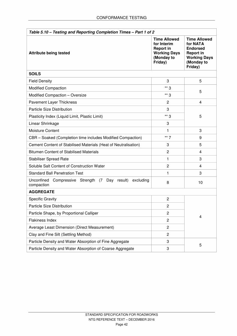
CONFORMANCE TESTING
STANDARD SPECIFICATION FOR ROADWORKS
NTG REFERENCE TEXT – DECEMBER 2016
Page 42
Table 5.10 – Testing and Reporting Completion Times – Part 1 of 2
Attribute being tested
Time Allowed for Interim Report in Working Days (Monday to Friday)
Time Allowed for NATA Endorsed Report in Working Days (Monday to Friday)
SOILS
Field Density 3 5
Modified Compaction ** 3 5
Modified Compaction – Oversize ** 3
Pavement Layer Thickness 2 4
Particle Size Distribution 3
5 Plasticity Index (Liquid Limit, Plastic Limit) ** 3
Linear Shrinkage 3
Moisture Content 1 3
CBR – Soaked (Completion time includes Modified Compaction) ** 7 9
Cement Content of Stabilised Materials (Heat of Neutralisation) 3 5
Bitumen Content of Stabilised Materials 2 4
Stabiliser Spread Rate 1 3
Soluble Salt Content of Construction Water 2 4
Standard Ball Penetration Test 1 3
Unconfined Compressive Strength (7 Day result) excluding compaction
8 10
AGGREGATE
Specific Gravity 2
4
Particle Size Distribution 2
Particle Shape, by Proportional Calliper 2
Flakiness Index 2
Average Least Dimension (Direct Measurement) 2
Clay and Fine Silt (Settling Method) 2
Particle Density and Water Absorption of Fine Aggregate 3 5
Particle Density and Water Absorption of Coarse Aggregate 3
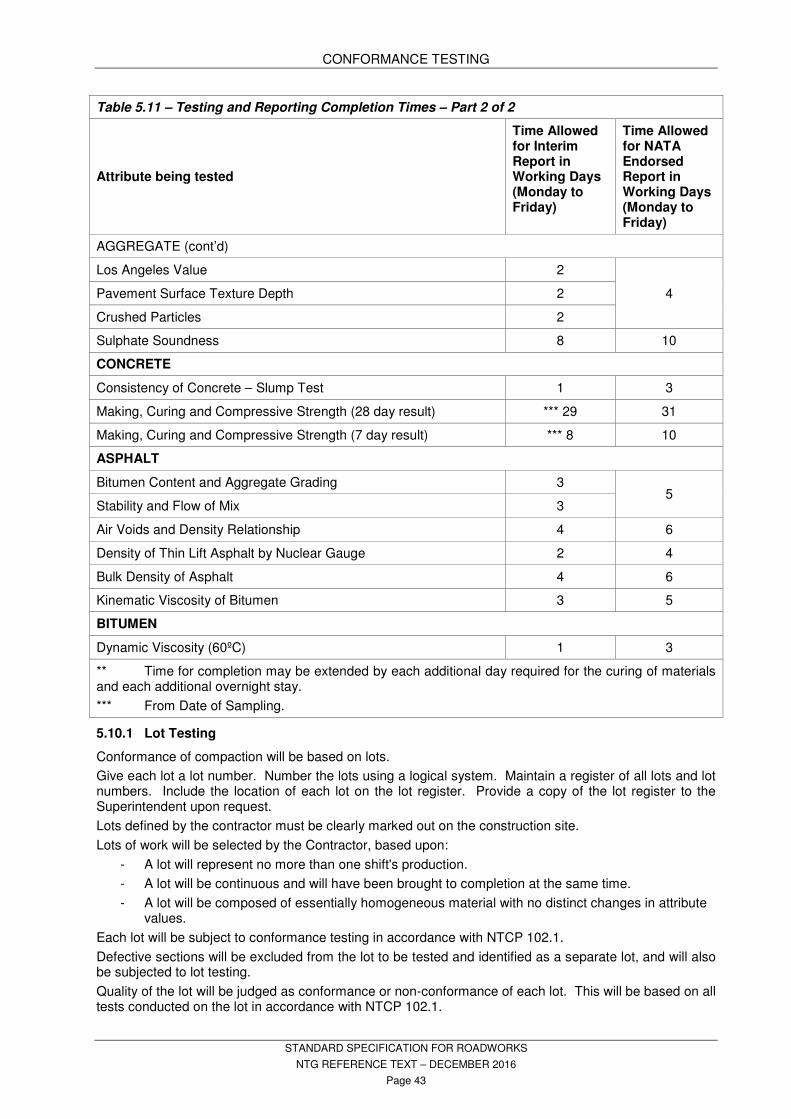
CONFORMANCE TESTING
STANDARD SPECIFICATION FOR ROADWORKS
NTG REFERENCE TEXT – DECEMBER 2016
Page 43
Table 5.11 – Testing and Reporting Completion Times – Part 2 of 2
Attribute being tested
Time Allowed for Interim Report in Working Days (Monday to Friday)
Time Allowed for NATA Endorsed Report in Working Days (Monday to Friday)
AGGREGATE (cont’d)
Los Angeles Value 2
4 Pavement Surface Texture Depth 2
Crushed Particles 2
Sulphate Soundness 8 10
CONCRETE
Consistency of Concrete – Slump Test 1 3
Making, Curing and Compressive Strength (28 day result) *** 29 31
Making, Curing and Compressive Strength (7 day result) *** 8 10
ASPHALT
Bitumen Content and Aggregate Grading 3 5
Stability and Flow of Mix 3
Air Voids and Density Relationship 4 6
Density of Thin Lift Asphalt by Nuclear Gauge 2 4
Bulk Density of Asphalt 4 6
Kinematic Viscosity of Bitumen 3 5
BITUMEN
Dynamic Viscosity (60ºC) 1 3
** Time for completion may be extended by each additional day required for the curing of materials and each additional overnight stay.
*** From Date of Sampling.
Lot Testing 5.10.1
Conformance of compaction will be based on lots.
Give each lot a lot number. Number the lots using a logical system. Maintain a register of all lots and lot numbers. Include the location of each lot on the lot register. Provide a copy of the lot register to the Superintendent upon request.
Lots defined by the contractor must be clearly marked out on the construction site.
Lots of work will be selected by the Contractor, based upon:
- A lot will represent no more than one shift's production.
- A lot will be continuous and will have been brought to completion at the same time.
- A lot will be composed of essentially homogeneous material with no distinct changes in attribute values.
Each lot will be subject to conformance testing in accordance with NTCP 102.1.
Defective sections will be excluded from the lot to be tested and identified as a separate lot, and will also be subjected to lot testing.
Quality of the lot will be judged as conformance or non-conformance of each lot. This will be based on all tests conducted on the lot in accordance with NTCP 102.1.

CONFORMANCE TESTING
STANDARD SPECIFICATION FOR ROADWORKS
NTG REFERENCE TEXT – DECEMBER 2016
Page 44
Conformance of materials is based on samples from the finished works.
When lots fail to satisfy the conformance criteria, reprocess the entire lot and resubmit for retesting.
Should the lot under consideration be subdivided then each subdivision will be classed as a lot and each subdivided lot will be subject to lot testing.
Non-conforming lots which are subdivided after testing will be treated as separate lots and each and every subdivided lot will be retested.
Conformance of Compaction of Soils 5.10.2
Density test locations will be selected by the laboratory on a stratified random basis in accordance with NTCP 103.1.
In situ density is expressed as a percentage of the Maximum Modified Dry Density. One Modified Dry Density test for each in situ density test will apply.
In situ density will be determined and reported in accordance with NTCP 102.1 and relevant Australian Standards.
A minimum of three tests will apply to each and every lot.
The Mean Dry Density Ratio (R) is calculated as follows:
n
xR
i∑=
xi = an individual test result
n = the number of results in the lot.
The Characteristic Mean Dry Density Ratio (Rc) is calculated as follows:
skRRc ∗−=
where:
R = the mean dry density ratio for the lot
k = the multiplier in Table 5.13 – Multiplier Values for Soils.
s = the standard deviation.
The Standard Deviation (s) is calculated as follows:
( )
( )1
2
−
−=∑
n
Rxs
i
where:
xi = an individual test result
R = the mean of n results
N = the number of test results in the lot.
When less than six tests are used to determine conformance of a lot the Mean Dry Density Ratios in Table 5.12 – Dry Density Ratios for Conformance, Column A apply.
When six or more tests are used to determine conformance of a lot the Characteristic Mean Dry Density Ratios in Table 5.12 – Dry Density Ratios for Conformance, Column B, apply.
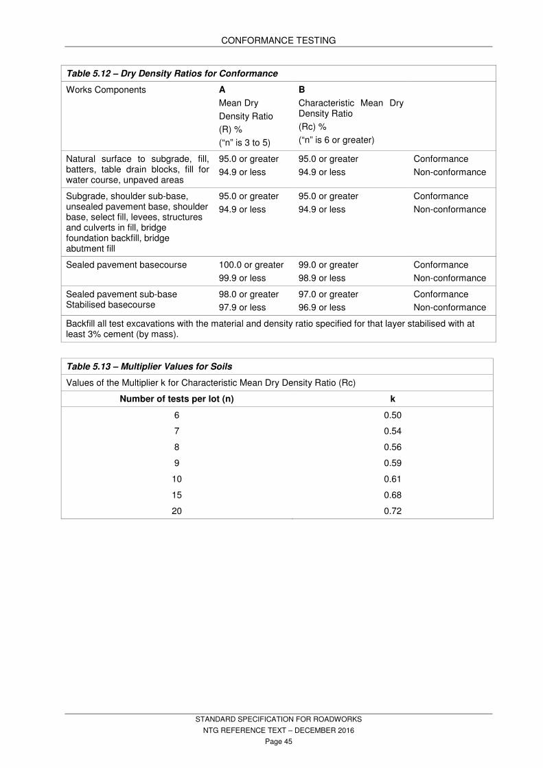
CONFORMANCE TESTING
STANDARD SPECIFICATION FOR ROADWORKS
NTG REFERENCE TEXT – DECEMBER 2016
Page 45
Table 5.12 – Dry Density Ratios for Conformance
Works Components A
Mean Dry
Density Ratio
(R) %
(“n” is 3 to 5)
B
Characteristic Mean Dry Density Ratio
(Rc) %
(“n” is 6 or greater)
Natural surface to subgrade, fill, batters, table drain blocks, fill for water course, unpaved areas
95.0 or greater
94.9 or less
95.0 or greater
94.9 or less
Conformance
Non-conformance
Subgrade, shoulder sub-base, unsealed pavement base, shoulder base, select fill, levees, structures and culverts in fill, bridge foundation backfill, bridge abutment fill
95.0 or greater
94.9 or less
95.0 or greater
94.9 or less
Conformance
Non-conformance
Sealed pavement basecourse 100.0 or greater
99.9 or less
99.0 or greater
98.9 or less
Conformance
Non-conformance
Sealed pavement sub-base Stabilised basecourse
98.0 or greater
97.9 or less
97.0 or greater
96.9 or less
Conformance
Non-conformance
Backfill all test excavations with the material and density ratio specified for that layer stabilised with at least 3% cement (by mass).
Table 5.13 – Multiplier Values for Soils
Values of the Multiplier k for Characteristic Mean Dry Density Ratio (Rc)
Number of tests per lot (n) k
6 0.50
7 0.54
8 0.56
9 0.59
10 0.61
15 0.68
20 0.72
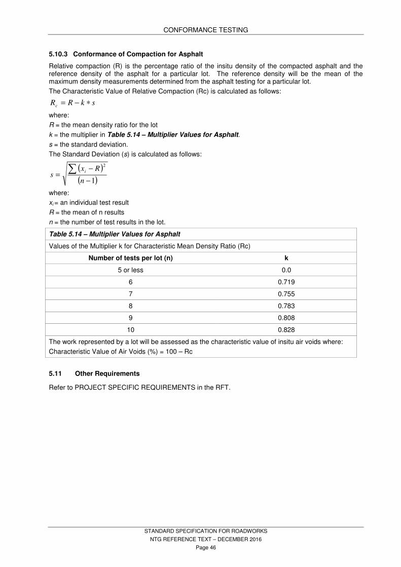
CONFORMANCE TESTING
STANDARD SPECIFICATION FOR ROADWORKS
NTG REFERENCE TEXT – DECEMBER 2016
Page 46
Conformance of Compaction for Asphalt 5.10.3
Relative compaction (R) is the percentage ratio of the insitu density of the compacted asphalt and the reference density of the asphalt for a particular lot. The reference density will be the mean of the maximum density measurements determined from the asphalt testing for a particular lot.
The Characteristic Value of Relative Compaction (Rc) is calculated as follows:
skRRc ∗−=
where:
R = the mean density ratio for the lot
k = the multiplier in Table 5.14 – Multiplier Values for Asphalt.
s = the standard deviation.
The Standard Deviation (s) is calculated as follows:
( )
( )1
2
−
−=∑
n
Rxs
i
where:
xi = an individual test result
R = the mean of n results
n = the number of test results in the lot.
Table 5.14 – Multiplier Values for Asphalt
Values of the Multiplier k for Characteristic Mean Density Ratio (Rc)
Number of tests per lot (n) k
5 or less 0.0
6 0.719
7 0.755
8 0.783
9 0.808
10 0.828
The work represented by a lot will be assessed as the characteristic value of insitu air voids where:
Characteristic Value of Air Voids (%) = 100 – Rc
Other Requirements 5.11
Refer to PROJECT SPECIFIC REQUIREMENTS in the RFT.

PAVEMENTS AND SHOULDERS
STANDARD SPECIFICATION FOR ROADWORKS
NTG REFERENCE TEXT – DECEMBER 2016
Page 47
6. PAVEMENTS AND SHOULDERS
6.1 STANDARDS
Conform to the following Standards and Publication unless specified otherwise:
AS 1141 Methods for sampling and testing aggregates.
AS 1289 Methods of testing soils for engineering purposes.
NTMTM NT Materials Testing Manual. NTTM NT Test Methods
6.2 DEFINITIONS
BASE (BASE COURSE):
That upper-most layer of constructed material immediately above the subgrade or sub-base and below the pavement surface (sealed or unsealed) extending for the full width of the pavement and shoulder.
IRI
International Roughness Index.
PAVEMENT:
That portion of a road constructed for the structural support of, and to form the running surface, for traffic.
The pavement structure refers to the pavement layers, in combination, above the subgrade surface, to support the traffic loadings. May be sealed or unsealed. Excludes the shoulders.
SHOULDER:
That layer of material immediately above the sub-base or subgrade and adjacent to the pavement. May be sealed or unsealed.
SUB-BASE:
One or more layers of material placed over the subgrade and below the basecourse extending for the full width of the pavement and shoulder.
6.3 MATERIAL PROPERTIES
6.3.1 Natural Gravel
Obtain natural gravel from sources of naturally occurring deposits.
Produce required properties by crushing, screening, mixing or other processes necessary.
Ensure particles are tough, durable and of a tightly binding nature free of organic or other deleterious materials.
Conform to Table 6.1 - Natural Gravel Particle Sizes and Table 6.2 - Natural Gravel Properties in the finished condition.
Table 6.1 - Natural Gravel Particle Sizes
AS Sieve (mm) Percentage Passing
Type 1 Type 2 Type 3 Type 4
75.0 100 - - 100
37.5 80-100 100 - 80-100
19.0 50-80 70-100 100 60-100
9.5 35-65 50-80 70-100 50-95
4.75 25-50 35-65 50-80 40-80
2.36 15-40 25-50 35-65 30-65
0.425 7-20 10-30 15-35 20-50
0.075 3-13 4-16 6-20 5-25
Refer to PROJECT SPECIFIC REQUIREMENTS in the RFT for requirements.
Generally Type 2 or Type 3 for Base (Sealed/Unsealed), Type 1, Type 2, Type 3 or Type 4 for Sub-base, and Type 3 for Shoulder Material.
6.3.2 Fine Crushed Rock
Manufacture from hard rock quarry operations by crushing clean, hard, durable rock free from natural gravel, clay, loam or other deleterious substances.
Conform to Table 6.3 – Fine Crushed Rock Particle Sizes and Table 6.4 – Fine Crushed Rock Properties in the finished condition.
Refer to PROJECT SPECIFIC REQUIREMENTS in the RFT

PAVEMENTS AND SHOULDERS
STANDARD SPECIFICATION FOR ROADWORKS
NTG REFERENCE TEXT – DECEMBER 2016
Page 48
Table 6.2 - Natural Gravel Properties
Attribute
Application
Northern Area - Sealed base
Southern Area – Sealed Base*
Unsealed Base And Shoulder Material
Sub-Base
Liquid Limit (LL) 25% max 30% 35% max
30% max
Plasticity Index (PI)
1-6% 1 - 10% 4 – 12 % 1-10%
Linear Shrinkage (LS)
0-3% 0 - 6% 2 – 8 % 0-6%
PI x % passing 0.425 mm Sieve
180 max 300 max 400 max 400 max
California Bearing Ratio (CBR)
4 day soaked (AS 1289)
80 min 80 min 50 min 30 min
at a relative density of
100% MMDD 100% MMDD 95% MMDD 95% MMDD
(Highest CBR value to be reported)
Los Angeles Abrasion (LAA) Loss
50 max 60 max 60 max 50 max
*Note: Southern Area- Sealed Base* applies to south of a line connecting Birrindudu - Dunmarra - Wollogorang.
Table 6.4 – Fine Crushed Rock Properties
Liquid Limit (LL) 25% max.
Plasticity Index (PI) 1 - 6%
Linear Shrinkage (LS)
3% max.
Dust Ratio (DR)
(% passing 0.075 mm)/(% passing 0.425 mm) x 100
25 - 50
CBR, 4 day soaked at 100% MMDD at 2.5 mm penetration (AS 1289)
100 min.
Los Angeles Abrasion (LAA)Loss:
coarse grained rock
fine grained rock
35% max.
25% max.
PI x % passing 0.425 mm sieve 180 max.
6.3.3 Blends of Natural Gravel and Fine Crushed Rock
Not permitted in urban areas for sealed pavements.
Conform to Table 6.1 - Natural Gravel Particle Sizes and Table 6.2 - Natural Gravel Properties in the finished condition.
Use for heavily trafficked situations and where material is available.
Refer to PROJECT SPECIFIC REQUIREMENTS in the RFT.
6.3.4 Sand Clay
Comply with this clause when sand clay forms an integral part of the pavement and/or shoulder design.
Table 6.3 – Fine Crushed Rock Particle Sizes
AS Sieve (mm) Percentage Passing
37.5 100
19.0 90 - 100
13.2 75 - 90
9.5 60 - 80
4.75 38 - 60
2.36 25 - 45
0.425 12 - 26
0.075 6 - 14
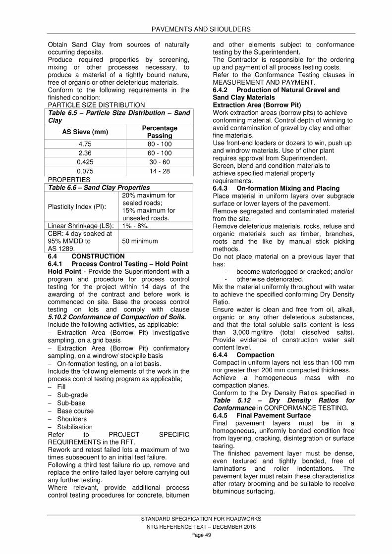
PAVEMENTS AND SHOULDERS
STANDARD SPECIFICATION FOR ROADWORKS
NTG REFERENCE TEXT – DECEMBER 2016
Page 49
Obtain Sand Clay from sources of naturally occurring deposits. Produce required properties by screening, mixing or other processes necessary, to produce a material of a tightly bound nature, free of organic or other deleterious materials. Conform to the following requirements in the finished condition: PARTICLE SIZE DISTRIBUTION Table 6.5 – Particle Size Distribution – Sand Clay
AS Sieve (mm) Percentage
Passing
4.75 80 - 100
2.36 60 - 100
0.425 30 - 60
0.075 14 - 28
PROPERTIES Table 6.6 – Sand Clay Properties
Plasticity Index (PI):
20% maximum for sealed roads; 15% maximum for unsealed roads.
Linear Shrinkage (LS): 1% - 8%. CBR: 4 day soaked at 95% MMDD to AS 1289.
50 minimum
6.4 CONSTRUCTION 6.4.1 Process Control Testing – Hold Point Hold Point - Provide the Superintendent with a program and procedure for process control testing for the project within 14 days of the awarding of the contract and before work is commenced on site. Base the process control testing on lots and comply with clause 5.10.2 Conformance of Compaction of Soils. Include the following activities, as applicable: − Extraction Area (Borrow Pit) investigative sampling, on a grid basis − Extraction Area (Borrow Pit) confirmatory sampling, on a windrow/ stockpile basis − On-formation testing, on a lot basis. Include the following elements of the work in the process control testing program as applicable; − Fill − Sub-grade − Sub-base − Base course − Shoulders − Stabilisation Refer to PROJECT SPECIFIC REQUIREMENTS in the RFT. Rework and retest failed lots a maximum of two times subsequent to an initial test failure. Following a third test failure rip up, remove and replace the entire failed layer before carrying out any further testing. Where relevant, provide additional process control testing procedures for concrete, bitumen
and other elements subject to conformance testing by the Superintendent. The Contractor is responsible for the ordering up and payment of all process testing costs. Refer to the Conformance Testing clauses in MEASUREMENT AND PAYMENT. 6.4.2 Production of Natural Gravel and Sand Clay Materials Extraction Area (Borrow Pit) Work extraction areas (borrow pits) to achieve conforming material. Control depth of winning to avoid contamination of gravel by clay and other fine materials. Use front-end loaders or dozers to win, push up and windrow materials. Use of other plant requires approval from Superintendent. Screen, blend and condition materials to achieve specified material property requirements. 6.4.3 On-formation Mixing and Placing Place material in uniform layers over subgrade surface or lower layers of the pavement. Remove segregated and contaminated material from the site. Remove deleterious materials, rocks, refuse and organic materials such as timber, branches, roots and the like by manual stick picking methods. Do not place material on a previous layer that has:
- become waterlogged or cracked; and/or - otherwise deteriorated.
Mix the material uniformly throughout with water to achieve the specified conforming Dry Density Ratio. Ensure water is clean and free from oil, alkali, organic or any other deleterious substances, and that the total soluble salts content is less than 3,000 mg/litre (total dissolved salts). Provide evidence of construction water salt content level. 6.4.4 Compaction Compact in uniform layers not less than 100 mm nor greater than 200 mm compacted thickness. Achieve a homogeneous mass with no compaction planes. Conform to the Dry Density Ratios specified in Table 5.12 – Dry Density Ratios for Conformance in CONFORMANCE TESTING. 6.4.5 Final Pavement Surface Final pavement layers must be in a homogeneous, uniformly bonded condition free from layering, cracking, disintegration or surface tearing. The finished pavement layer must be dense, even textured and tightly bonded, free of laminations and roller indentations. The pavement layer must retain these characteristics after rotary brooming and be suitable to receive bituminous surfacing.

PAVEMENTS AND SHOULDERS
STANDARD SPECIFICATION FOR ROADWORKS
NTG REFERENCE TEXT – DECEMBER 2016
Page 50
Allow the top 75 mm of the pavement layer to dry back to a Moisture Ratio (Rm) equal or less than 65% for FCR and 70% for natural gravel.
Moisture Ratio (Rm) is defined as follows:
Rm = (100 x wf)
wr
where:
Rm = Moisture Ratio, in percent
wf = field moisture content, in percent
wr = adjusted optimum moisture content, in percent.
The Superintendent will carry out all testing to determine the Moisture Ratio. Remove sticks and any loose material. Ensure surface is free of cracking. Do not introduce new material to the surface after final compaction. Where pavement thickness is 200 mm or greater, scarify to not less than 100 mm depth and recompact where finish not achieved. Where pavement thickness is less than 200 mm scarify and recompact to full depth where finish not achieved. 6.5 RECONSTRUCTION AND REHABILITATION OF EXISTING PAVEMENTS 6.5.1 Widening Saw cut back the existing pavement by not less than 150 mm width on each edge to sound material. Excavate boxing for widening to the required depth below finished surface. Construct subgrade as specified in EARTHWORKS. Construct pavement and shoulder as specified. 6.5.2 Strengthening by Granular Overlay on Existing Pavement This clause is not applicable to pavements which are not sealed. Saw cut across existing pavement at each end of work. Cut shall be vertical and at least 100 mm deep to allow smooth transition to new work. If sealed, remove seal from existing pavement. Scarify local high spots to 75 mm below finished surface. Construct a strengthening layer over the full width of the existing pavement and shoulder and the widening as specified. 6.5.3 Strengthening by Granular Overlay on Re-worked Existing Sealed Pavement This clause is not applicable to pavements which are not sealed. Saw cut across existing pavement at each end of work. Cut shall be vertical and at least 100 mm deep to allow smooth transition to new work.
Cut and/or add top-up gravel where required to achieve levels and gradelines. Wet mix existing seal into existing base layer, with pulveriser-mixing plant, to nominal depth specified. Moisture condition and compact re-worked existing pavement to the Dry Density Ratios specified in Table 5.12 – Dry Density Ratios for Conformance in CONFORMANCE TESTING for sub-base requirements. Construct a new strengthening basecourse layer over the full width of the re-worked pavement and shoulder, and any widening, to thickness specified. Moisture condition and compact pavement to the Dry Density Ratios specified in Table 5.12 – Dry Density Ratios for Conformance in CONFORMANCE TESTING for sealed base course requirements. 6.6 SUPPLY TO STOCKPILE Comply with the following stockpile requirements;
- Clear the site. - Ensure the area is free draining. - Spread and compact a 75 mm thick
layer of sub-base gravel to 95% relative compaction.
- Trim stockpile to a uniform shape for ease of measurement.
6.7 CONFORMANCE 6.7.1 Tolerances
Refer MISCELLANEOUS PROVISIONS, 1.17 Level Checking and 1.18 Level Auditing.
Table 6.7 - Final Surfaces Tolerances
Final surfaces shall conform to the following:
Level: Kerbed or Asphalt:
0 mm to +10 mm.
Level: Otherwise: -20 mm to +20 mm.
Straight Edge Deviation:
maximum 5 mm in 3 m.
Compacted Thickness:
not less than specified.
Width: not less than specified.
Sub-base Surface Level:
not higher than specified.
Surface Roughness at 80 km/h:
IRI 2.4 maximum.
6.7.2 Proof Rolling – Hold Point – Witness Point
Proof roll all areas and obtain satisfactory results before ordering conformance testing of those areas.
Hold point - Submit a proof rolling procedure to the Superintendent for approval including the method of preparing an area and the extent of proof rolling.

PAVEMENTS AND SHOULDERS
STANDARD SPECIFICATION FOR ROADWORKS
NTG REFERENCE TEXT – DECEMBER 2016
Page 51
Witness point - Give the Superintendent not less than 24 hours notice of the location and commencement time for the proof rolling.
Plant Requirements; use plant in proof rolling procedures that comply with the following requirements:
- Static smooth wheeled rollers with a mass of not less than 12 tonnes and a load intensity under either the front or rear wheels of not less than 6 tonnes per metre width of wheel.
- Pneumatic tyred plant with a mass of not less than 20 tonnes and with a ground contact pressure under either the front or rear wheels of not less than 450 kPa per tyre and a ground contact area of not less than .035 m2 per tyre.
Check areas for level tolerance and layer thickness before proof rolling.
Proof roll each layer immediately following completion of compaction. If proof rolling is carried out at a later time, water the surface and roll with the test roller prior to commencement of proof rolling.
Compliance; the proof rolling requirements are deemed to comply when an area withstands proof rolling without visible deformation or springing.
Remedial work; remove and reconstruct areas that deform or break up.
6.7.3 Conformance Testing – Hold Point Ordering procedures; refer to the CONFORMANCE TESTING section for testing requirements and test ordering procedures.
Only the finished compacted base, sub-base and shoulder conforming to proof rolling, level tolerance and layer thickness will be tested.
Pavements and shoulders will be considered as separate lots.
Hold point – Obtain the Superintendent’s approval for pavement conformance prior to any surfacing work.
Backfill and compact all test holes with cement stabilised quality material which is the same as the layer being tested.
6.7.4 Ride Quality Surface Roughness (IRI) to be less than 2.4.
Ride quality requirements represent an absolute upper limit and all field values to be less than value specified.
Lotting and averaging out of field values not permitted.
Rectify all areas where Surface Roughness exceeds specified level.
Exclusions are listed below in the Exclusions to specified roughness limits clause.
Surface roughness testing is to be carried out as directed by the Superintendent. When lots fail to
meet the conformance criteria, rejection of the lot or payment adjustments will be applied. Refer to Table 23.3 - Rate of Payment Adjustments in MEASUREMENT AND PAYMENT, Rate of Payment Adjustment clause.
6.7.5 Roughness testing sequence Data must be collected in the sequence shown in the table within 5 days of completion of testing of the relevant pavement layer.
Ensure that; the pavement is free of loose material and debris when testing is done, for unbound granular bases, measurements must be undertaken prior to sweeping of the pavement, and free water is not present on the pavement when testing is undertaken.
Table - Testing sequence for pavement type Pavement type Testing sequence
Spray seal on granular base
Before application of spray seal and after completion of the final wearing surface.
Asphalt Overlays and Thin Shape correcting Surfaces (thickness < 50 mm )
After all rehabilitation work is complete but before asphalt overlay has commenced. Also required on final wearing course.
Asphalt pavement (thickness 50 mm and over)
Prior to , and after, the application of the final wearing course.
6.7.6 Exclusions to specified roughness limits
Unless specified otherwise in the PROJECT SPECIFIC REQUIREMENTS (PSRs), the following areas are excluded from the requirement to achieve an IRI of less that 2.4:
- Roundabouts - Railway lines (35 m after the event) - Bridge joints (35 m after the event) - Intersections (stop bar to stop bar) - Inspection pit covers and related surface
defects within the wheel paths (15 m including the event)
- Side streets specified in the PSRs deemed to affect pavement ride quality (the width of the side street plus 30 m after the event)
- Surface defects related to existing culverts which are not part of the works under the Contract (width of culvert plus 30 m after the event), and
- Cattle grids. 6.8 OTHER REQUIREMENTS
Refer to PROJECT SPECIFIC REQUIREMENTS in THE RFT.
STABILISATION
STANDARD SPECIFICATION FOR ROADWORKS
NTG REFERENCE TEXT – DECEMBER 2016
Page 52
7. STABILISATION
7.1 STANDARDS
Conform to the following Standards and Publication unless specified otherwise:
AS 1141 Methods for sampling and testing aggregates.
AS 1160 Bitumen emulsions for construction and maintenance of pavements.
AS 1289 Method of testing soils for engineering purposes.
AS 1478.1 Chemical admixtures for use in concrete.
AS 1672.1 Limes and limestones - Limes for building.
AS 2157 Cutback bitumen. AS 3972 Portland and blended cements. NTMTM NT Materials Testing Manual. NTTM NT Test Methods
7.2 DEFINITIONS
OPTIMUM MOISTURE CONTENT:
The amount of water by mass, expressed as a percentage of the dry mass of the material, at which maximum modified dry density is obtained with the stabiliser added.
7.3 MATERIALS
7.3.1 Stabiliser
Lime: Calcium Hydroxide (Hydrated Lime/Slaked Lime) Ca(OH)2 or Calcium Oxide (Quicklime/Burnt Lime) CaO conforming to AS 1672.1.
Do not use dolomite limes ( CaMg(CO3)2 ). Do not use agricultural lime (Calcium Carbonate CaCO3).
Cement: Type GP or GB.
Supply and store stabilisers in a manner that protects against the weather and moisture.
7.3.2 Additives
Follow manufacturer's recommendations when using retarders and water reducing additives.
7.3.3 Water
Ensure water is clean and free from oil, alkali, organic matter and other deleterious substances, and that the total soluble salts content is less than 3,000 mg/litre (total dissolved salts).
For Southern Regions amend the maximum salt content as instructed by the Superintendent.
7.3.4 Curing Agent
Surface applied curing membrane other than the use of water to be either:
Bitumen emulsion ARS Grade 320.
or
Cut-back bitumen Class AMC 2 or AMC 3.
7.3.5 Materials to be Stabilised
Refer to PROJECT SPECIFIC REQUIREMENTS for details of materials to be stabilised.
7.4 IN SITU STABILISATION
7.4.1 Preliminary Trial
Preliminary trial only for projects greater than 1000 m
2 in treated area.
Locate trial section within the works area.
Carry out a preliminary trial of the proposed operation to determine:
- effectiveness of mechanical plant;
- passes necessary to achieve the specified mixing;
- optimum curing time between preliminary and final mixing (lime stabiliser only); and
- field moisture content and plant pattern to achieve final compaction.
- Carry out all necessary process control testing for this purpose.
Conform to Dry Density Ratios specified in Table 5.12 – Dry Density Ratios for Conformance in CONFORMANCE TESTING.
7.4.2 Preparation of Layer
Scarify existing pavement sections and new material, where necessary, full depth before spreading.
Tyne the surface lightly when quicklime is used.
Compact lightly to reveal irregularities in the spread material and to permit the stabilising equipment to traverse the area without excessive displacement of the surface.
Shape and trim the surface to the alignment, levels and cross-sections necessary to produce the final levels and compacted thickness.
7.4.3 Commencement and Continuity of Work
Complete full width stabilisation in one day.
Cease stabilising during the following conditions:
- Wet weather or if rain is likely to fall.
- Windy periods which could cause loss of stabiliser, or dust nuisance.
STABILISATION
STANDARD SPECIFICATION FOR ROADWORKS
NTG REFERENCE TEXT – DECEMBER 2016
Page 53
7.4.4 Spreading – Hold Point
Select spread rate to achieve an unconfined compressive strength of 1.5 to 2.0 MPa.
Calibrate and check spread rate prior to commencement.
Adopt the following rate for tender purposes:
Cement: 6 kg/m2.
Hydrated Lime: 8 kg/m2.
Hold point - Assess spread rate based upon test results of materials to be stabilised. Obtain the Superintendent's approval of the spread rate.
QUICKLIME
Water the spread material sufficiently to allow full slaking.
Avoid overwatering.
LIME SLURRY
Initial mixing in separate paddle mixer or similar.
Use mechanical sprayer with agitation to maintain a lime/water ratio within ±10% of initial ratio.
Lime/water ratio: Generally between 1:2 (i.e. 1 tonne per 2000 litres) and 1:0.8 (i.e. 1 tonne per 800 litres), measured by mass.
7.4.5 Mixing
Use plant capable of:
- mixing the stabiliser with the nominated material uniformly over the full depth to be stabilised; and
- adding water uniformly to the materials while mixing with application rate between 0 to 10% (by mass) of the material being mixed.
Resultant mix to be uniform in colour and free of lenses, pockets or clumps of stabiliser.
Pulverise clayey material until at least 90% passes 19 mm sieve.
Add water to the materials during mixing to achieve a moisture content suitable for compaction.
CEMENT STABILISATION
Commence compaction and finishing immediately following satisfactory mixing.
LIME STABILISATION
Shape the treated layer to the approximate section after satisfactory mixing and lightly compact.
Cure for a period of 24 to 72 hours.
Commence final mixing.
Add water during final mixing if necessary to achieve moisture content suitable for compaction.
Resultant mix to be uniform in colour and free of lenses, pockets or clumps of lime.
7.4.6 Compaction
Compact parallel to the centre line of the pavement and for the full depth of the stabilised layer.
Commence compaction at the lower edge of the pavement and work progressively towards the crown or the higher edge.
Allow for progressive and uniform overlap between passes.
Wet the surface lightly after compaction to reduce moisture loss and lay the dust when necessary.
CEMENT STABILISATION
Complete the compacting and finishing within two hours of adding water.
7.4.7 Finishing
Final surface shall be smooth, dense, closely knit, free from compaction planes and cracks and finished to the tolerances specified.
Filling or addition of material to the surface of the pavement to meet tolerance requirements will not be permitted.
Maintain the surface material at not less than its specified optimum moisture content during all finishing operations.
Reconstruct non-complying areas at no cost to the Principal.
7.4.8 Construction Joints
LONGITUDINAL JOINTS
Minimise longitudinal joints by stabilising the full width of traffic lanes or wider as one continuous operation.
Joints to be straight or follow road curvature as appropriate.
TRANSVERSE JOINTS
Form joints following any break in excess of two hours in the continuity of the stabilisation operations.
Cut the end of the material to a plane face at an angle not exceeding 45 degrees from the vertical.
Check the surface adjacent to the joint with a straight edge prior to recommencement and further cut back the joint as necessary to achieve surface tolerance.
7.4.9 Curing
Keep the finished surface damp (without leaching) until further construction or curing operations are carried out.
Alternatively cure by applying a bitumen emulsion or a bitumen primer as specified.
Apply the bituminous curing membrane as soon as possible after mixing and compaction but no
STABILISATION
STANDARD SPECIFICATION FOR ROADWORKS
NTG REFERENCE TEXT – DECEMBER 2016
Page 54
later than 24 hours after relative compaction results are available.
Application rate for bitumen emulsions to be 0.3 to 0.45 litres per square metre.
Maintain clear of vehicular traffic for four days.
7.5 PLANT MIX STABILISATION
7.5.1 Stabiliser Content – Hold Point
Refer to PROJECT SPECIFIC REQUIREMENTS in the RFT for cement content percentage rate to be used for tender purposes.
Hold point - Assess the cement content based upon test results of materials to be stabilised. Obtain the Superintendent's approval for the cement content.
7.5.2 Preliminary Trial
For projects over 1000m2 in treated area.
Locate trial section within the works area.
Carry out a preliminary trial of the proposed operation to determine:
- effectiveness of mechanical plant; and
- field moisture content and plant pattern to achieve final compaction.
Test stabilised material for conformance with Table 5.12 – Dry Density Ratios for Conformance in CONFORMANCE TESTING.
7.5.3 Commencement and Continuity of Work
Complete full width stabilisation of pavement in one day.
Do not stabilise during wet weather or if rain is likely to fall.
7.5.4 Care of Existing Surface
Avoid damage to existing surface on which the mix is placed.
Repair any damage.
7.5.5 Mixing
Mixing plant to be capable of maintaining the mix proportions.
Add cement and water to material to be stabilised and mix for a minimum period of 30 seconds.
Material to be uniform and without segregation.
BATCH MIXER
Scales used for weighing cement for batching plants will be used solely for that purpose.
Proportion the dry materials by mass.
CONTINUOUS MIXER
Proportion the dry materials by volume.
Use a continuous feeder which allows feed rate of different aggregate sizes to be adjusted separately.
7.5.6 Delivery
Minimise segregation during loading and unloading and discharge directly into the hoppers of paving machines without spillage.
Provide open trucks with tarpaulins.
7.5.7 Laying
PAVING MACHINE
Deposit and spread the pavement material in one operation using self-propelled mechanical tamper-spreader.
Lay material uniformly without segregation to produce a uniform surface texture and required thickness.
GRADER LAYING
To be used on minor work only. Spread the material in one layer not less than 75 mm nor more than 200 mm compacted thickness.
7.5.8 Compaction, Finishing, Construction Joints and Curing
Conform to the requirements specified for in situ stabilisation.
7.6 CONFORMANCE
7.6.1 Tolerances
For stabilised layers conform to the tolerances specified in the PAVEMENTS AND SHOULDERS section and with Table 7.1 – Stabilised Layers Conformance:
7.6.2 Testing – Hold Point
STABILISER APPLICATION RATE
The Contractor shall be responsible for checking the application rate.
Determine the stabiliser application rate in accordance with NTTM 204.7.

STABILISATION
STANDARD SPECIFICATION FOR ROADWORKS
NTG REFERENCE TEXT – DECEMBER 2016
Page 55
Table 7.1 – Stabilised Layers Conformance
Dry Density Ratio:
Refer Table 5.12 – Dry Density Ratios for Conformance IN THE CONFORMANCE TESTING Section.
Stabiliser Application Rate/Content
±10% of the designated value averaged for each lot
Stabiliser Distribution:
[i] Stabiliser content shall not vary by more than 0.5% absolute between top and bottom half of a layer at any location as determined in accordance with NTTM 204.8.
[ii] Stabiliser content shall not vary by more than ±0.5% from the designated value in any point.
Moisture Content during Compaction:
[i]
[ii]
±1.5% of moisture content determined at preliminary trial.
±1.5% of optimum moisture content.
[i] apply if a preliminary trial is carried out (i.e. total area over 1000m2)
[ii] apply if a preliminary trial is not carried out (i.e. areas under 1000m2)
Take samples for Liquid Limit, Plastic Limit, Linear Shrinkage, California Bearing Ratio from the unstabilised pavements.
Refer to CONFORMANCE TESTING for Test Frequencies.
Correct application deficiencies by the application of additional stabiliser and remixing if mixing has already commenced.
STABILISER CONTENT
The Superintendent will carry out conformance testing.
COMPACTION
The Superintendent will carry out conformance testing.
Check areas for level tolerance and layer thickness before testing.
Only the finished compacted pavement complying with level tolerance and layer thickness will be tested.
Dry Density Ratios will be determined 24 hours after final compaction.
Backfill test holes within 24 hours of testing with new stabilised material.
Hold point - Superintendent to approve conformance of stabilised layer prior to priming.
7.6.3 Rideability
Surface roughness testing will be carried out by the Superintendent at the discretion of the Superintendent.
7.7 OTHER REQUIREMENTS
Refer to PROJECT SPECIFIC REQUIREMENTS in the RFT.

SPRAY SEALING
STANDARD SPECIFICATION FOR ROADWORKS
NTG REFERENCE TEXT – DECEMBER 2016
Page 56
8. SPRAY SEALING
8.1 STANDARDS
Conform to the following Standards and Publications unless specified otherwise:
AS 1141 Methods for sampling and testing aggregates
AS 1141.14 - Particle shape, by proportional caliper
AS 1141.15 - Flakiness index AS 1141.18 - Crushed particles in coarse
aggregate derived from gravel AS 1141.20.1 - Average least dimension –
Direct measurement (nominal size 10 mm and greater)
AS 1141.20.2 - Average least dimension – Direct measurement (nominal sizes 5 mm and 7mm)
AS 1141.23 - Los Angeles value AS 1141.24 - Aggregate soundness –
Evaluation by exposure to sodium sulphate solution
AS 1141.25.1 - Degradation factor – Source rock
AS 1141.26 - Secondary minerals content in igneous rocks
AS 1141.29 - Accelerated soundness index by reflux
AS 1141.40 - Polished aggregate friction value – Vertical road wheel machine
AS 1141.41 - Polished aggregate friction value – Horizontal bed machine
AS 1141.50 - Resistance to stripping of cover aggregates from binders
AS 1160 Bituminous emulsions for the construction and maintenance of pavements
AS 1742.3 Manual of uniform traffic control devices – Traffic control for works on roads
AS 1906.3 Retroreflective materials and devices for road traffic control purposes – Raised pavement markers
AS 2008 Residual bitumen for pavements
AS 2106.2 Methods for the determination of the flash point of flammable liquids (closed cup) - Penksy Martens closed cup method
AS 2157 Cutback bitumen AS 2341 (set) Methods of testing bitumen and
related roadmaking products AS 2341.6 - Determination of density using
a hydrometer AS 2341.9 - Determination of water content
(Dean and Stark) AS/NZS 2341.13 - Long-term exposure to
heat and air
AS 2758.2 Aggregates and rock for engineering purposes - Aggregate for sprayed bituminous surfacing
AS 2809.5 Road tank vehicles for dangerous goods - Tankers for bitumen based products
AS 3568 Oils for reducing the viscosity of residual bitumen for pavements
AS 3706 Geotextiles – Methods of Test AS 3706.1 - General requirements,
sampling, conditioning, basic physical properties and statistical analysis
AS 3706.2 - Determination of tensile properties – Wide strip and grab method
AS 3706.3 - Determination of tearing strength – Trapezoidal method
NORTHERN TERRITORY TEST METHODS NTTM 215.1 Standard bell penetration test NTTM 304.1 Determination of skid resistance
with the portable skid tester AMERICAN SOCIETY FOR TESTING AND
MATERIALS ASTM D86 Standard Test Method for
Distillation of Petroleum Products at Atmospheric Pressure
ASTM D445 Standard Test Method for Kinematic Viscosity of Transparent and Opaque Liquids (and Calculation of Dynamic Viscosity)
ASTM D1298 Standard Test Method for Kinematic Viscosity of Transparent and Opaque Liquids (and Calculation of Dynamic Viscosity)
AUSTROADS AGPT04H-08 Austroads Guide to Pavement
Technology – Part 4H: Test Methods
AGPT04K-09 Guide to Pavement Technology – Part 4K: Seals
AGPT/T103 Pre-treatment and Loss on Heating of Bitumen Multigrade and polymer Binders (rolling thin film oven [RTFO] test)
AGPT/T108 Segregation of Polymer Modified Binders
AGPT/T109 Ease of Remixing of Polymer Modified Binders
AGPT/T111 Handling Viscosity of Polymer Modified Binders (Brookfield Thermosel)
AGPT/T112 Flash Point of Polymer Modified Binders

SPRAY SEALING
STANDARD SPECIFICATION FOR ROADWORKS
NTG REFERENCE TEXT – DECEMBER 2016
Page 57
AGPT/T121 Shear Properties of Polymer Modified Binders (ARRB ELASTOMETER)
AGPT/T122 Torsional Recovery of Polymer Modified Binders
AGPT/T131 Softening Point of Polymer Modified Binders
AGPT/T132 Compressive Limit of Polymer Modified Binders
AGPT/T142 Rubber content of digested crumb rubber binders - Trichlor bath method
AGPT/T190 Specification Framework for Polymer Modified Binders and Multigrade Bitumens
AP-C87-15 Austroads Glossary of Terms AP-G41-08 Bituminous Materials Sealing
Safety Guide AP-T68/06 Update of the Austroads
Sprayed Seal Design Method AP-T235-13 Guide to the Selection and Use
of Polymer Modified Binders and Multigrade Bitumens
AP-T236-13 Update of Double/Double Design for Austroads Sprayed Seal Design Methods
NT Weeds Management Act
8.2 DEFINITIONS
Reference should be made to AUSTROADS – AP-C87-15 Austroads Glossary of Terms to give definitions on all aspects of Bituminous Surfacing works where required.
ADHESION AGENT:
A substance used for the purpose of promoting the adhesion between binder and aggregate.
ASTM American Society For Testing And Materials
COARSE GRAINED AGGREGATE:
Where the average grain size of the constituent minerals is greater than 1mm. The average grain size is determined optically under a petrographic microscope or by calibrated hand lens.
CUTTER (Kerosene):
A light petroleum distillate added to bitumen to temporarily reduce its viscosity.
DEPARTMENT, THE / DIPL
Department of Infrastructure, Planning and Logistics.
FINE GRAINED AGGREGATE:
Where the average grain size of the constituent minerals is less than 1mm. The average grain size is determined optically under a petrographic microscope or by calibrated hand lens.
FLUX OIL:
A petroleum distillate added to bitumen to produce a long term reduction in its viscosity.
NATA
National Association of Testing Authorities
NTCP Northern Territory Code of Practice
NTMTM NT Materials Testing Manual – available at https://infrastructure.nt.gov.au/technical-information/materials-testing-manual
NTTM NT Test Method
PMB Polymer Modified Binder
PRECOATING MATERIAL:
A material used for pre-coating aggregate to promote adhesion of bitumen. Do not use Diesel.
PRIME:
An application of a Primer to a prepared base without cover aggregate to provide penetration of the surface temporary waterproofing and to obtain a bond between the pavement and the subsequent seal or asphalt. It is a preliminary treatment to a more permanent bituminous surface. No Diesel products.
PRIMERSEAL:
An application of primer binder with a fine cover aggregate to a prepared base to provide penetration of the surface and retain a light cover aggregate.
RESEAL: A seal applied to an existing sealed, asphalt or concrete surface.
SAMI: Strain Alleviating Membrane Interlayer
SEAL: A sprayed application of bituminous binder into which aggregate is incorporated. May include more than one application of binder and aggregate, and may include geotextile fabric.
8.3 SCOPE
Spray sealing treatments include:
Prime
Primerseal
Enrichments
Initial Seal or Reseal:
- With conventional bitumen, cutback bitumen or bitumen emulsion binder
- With modified binder
- Incorporating geotextile fabric reinforcement.
Spray sealing work consists of:
- Supply and delivery of materials.
- Storage and handling of raw materials.
- Precoating of aggregate.
- Preparation of pavement surfaces.
- Preparation of bituminous materials.
- Recording of spray sealing works.
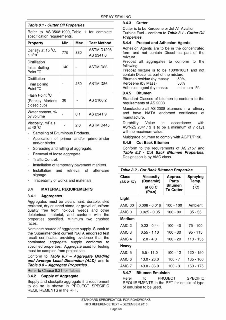
SPRAY SEALING
STANDARD SPECIFICATION FOR ROADWORKS
NTG REFERENCE TEXT – DECEMBER 2016
Page 58
- Sampling of Bituminous Products.
- Application of primer and/or primerbinder and/or binder.
- Spreading and rolling of aggregate.
- Removal of loose aggregate.
- Traffic Control.
- Installation of temporary pavement markers.
- Installation and retrieval of after-care signage.
- Traceability of works and materials.
8.4 MATERIAL REQUIREMENTS
8.4.1 Aggregates
Aggregates must be clean, hard, durable, skid resistant, dry crushed stone, or gravel of uniform quality free from noxious weeds and other deleterious material, and conform with the properties specified. Minimum two crushed faces.
Nominate source of aggregate supply. Submit to the Superintendent current NATA endorsed test result certificates providing evidence that the nominated aggregate supply conforms to specified properties. Aggregate used for testing must be sampled from project site.
Conform to Table 8.7 – Aggregate Grading and Average Least Dimension (ALD), and to Table 8.8 – Aggregate Properties.
Refer to Clause 8.21 for Tables
8.4.2 Supply of Aggregate
Supply and stockpile aggregate if a requirement to do so is shown in PROJECT SPECIFIC REQUIREMENTS in the RFT.
8.4.3 Cutter
Cutter is to be Kerosene or Jet A1 Aviation Turbine Fuel – conform to Table 8.1 - Cutter Oil Properties.
8.4.4 Precoat and Adhesion Agents
Adhesion Agents are to be in the concentrated form and not contain Diesel as part of the mixture. Precoat all aggregates to conform to the following: Precoat mixture is to be 100/0/100/1 and not contain Diesel as part of the mixture. Bitumen residue (by mass): 50%. Kerosene (by Mass) 50% Adhesion agent (by mass): minimum 1%
8.4.5 Bitumen
Standard Classes of bitumen to conform to the requirements of AS 2008.
Manufacture all AS 2008 bitumens in a refinery and have NATA endorsed certificates of manufacture.
Durability Value in accordance with AS/NZS 2341.13 is to be a minimum of 7 days with no maximum value.
Multigrade bitumen to comply with AGPT/T190.
8.4.6 Cut Back Bitumen
Conform to the requirements of AS 2157 and Table 8.2 - Cut Back Bitumen Properties. Designation is by AMC class.
8.4.7 Bitumen Emulsion
Refer to PROJECT SPECIFIC REQUIREMENTS in the RFT for details of type of emulsion to be used.
Table 8.1 - Cutter Oil Properties
Refer to AS 3568:1999, Table 1 for complete specification requirements.
Property Min. Max Test Method
Density at 15 oC,
km/m3 775 830
ASTM D1298
AS 2341.6
Distillation
Initial Boiling Point
oC
140 - ASTM D86
Distillation
Final Boiling Point
oC
- 280 ASTM D86
Flash Point oC
(Penksy -Martens closed cup)
38 - AS 2106.2
Water content, % by volume
- 0.1 AS 2341.9
Viscosity, mPa.s at 40
oC
- 2.0 ASTM D445
Table 8.2 - Cut Back Bitumen Properties
Class
(AS 2157)
Viscosity (Dynamic)
at 60°C
(Pa.s)
Approx. Parts
Bitumen To Cutter
Spraying Temp.
(°C)
Light
AMC 00 0.008 - 0.016 100 - 100 Ambient
AMC 0 0.025 - 0.05 100 - 80 35 - 55
Medium
AMC 2 0.22 - 0.44 100 - 40 75 - 100
AMC 3 0.55 - 1.10 100 - 30 95 - 115
AMC 4 2.0 - 4.0 100 - 20 110 - 135
Heavy
AMC 5 5.5 - 11.0 100 - 12 120 - 150
AMC 6 13.0 - 26.0 100 - 7 135 - 160
AMC 7 43.0 - 86.0 100 - 3 150 - 175
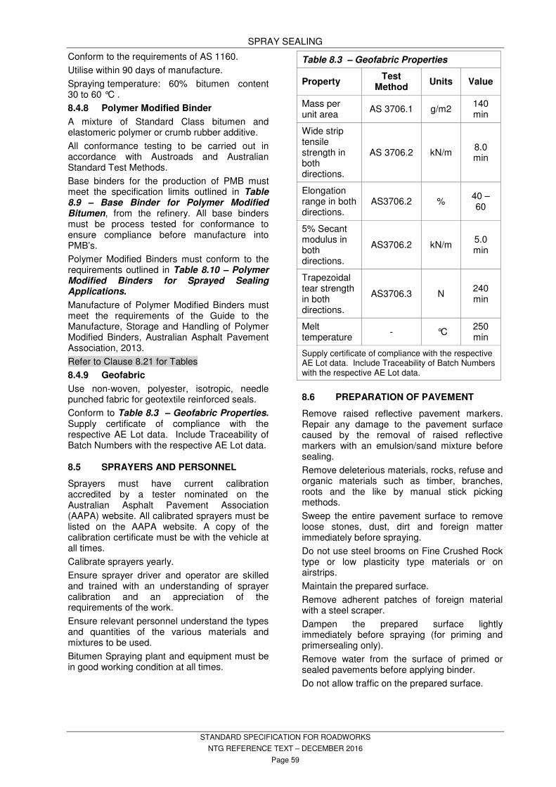
SPRAY SEALING
STANDARD SPECIFICATION FOR ROADWORKS
NTG REFERENCE TEXT – DECEMBER 2016
Page 59
Conform to the requirements of AS 1160.
Utilise within 90 days of manufacture.
Spraying temperature: 60% bitumen content 30 to 60 °C .
8.4.8 Polymer Modified Binder
A mixture of Standard Class bitumen and elastomeric polymer or crumb rubber additive.
All conformance testing to be carried out in accordance with Austroads and Australian Standard Test Methods.
Base binders for the production of PMB must meet the specification limits outlined in Table 8.9 – Base Binder for Polymer Modified Bitumen, from the refinery. All base binders must be process tested for conformance to ensure compliance before manufacture into PMB’s.
Polymer Modified Binders must conform to the requirements outlined in Table 8.10 – Polymer Modified Binders for Sprayed Sealing Applications.
Manufacture of Polymer Modified Binders must meet the requirements of the Guide to the Manufacture, Storage and Handling of Polymer Modified Binders, Australian Asphalt Pavement Association, 2013.
Refer to Clause 8.21 for Tables
8.4.9 Geofabric
Use non-woven, polyester, isotropic, needle punched fabric for geotextile reinforced seals.
Conform to Table 8.3 – Geofabric Properties. Supply certificate of compliance with the respective AE Lot data. Include Traceability of Batch Numbers with the respective AE Lot data.
8.5 SPRAYERS AND PERSONNEL
Sprayers must have current calibration accredited by a tester nominated on the Australian Asphalt Pavement Association (AAPA) website. All calibrated sprayers must be listed on the AAPA website. A copy of the calibration certificate must be with the vehicle at all times.
Calibrate sprayers yearly.
Ensure sprayer driver and operator are skilled and trained with an understanding of sprayer calibration and an appreciation of the requirements of the work.
Ensure relevant personnel understand the types and quantities of the various materials and mixtures to be used.
Bitumen Spraying plant and equipment must be in good working condition at all times.
Table 8.3 – Geofabric Properties
Property Test
Method Units Value
Mass per unit area
AS 3706.1 g/m2 140 min
Wide strip tensile strength in both directions.
AS 3706.2 kN/m 8.0 min
Elongation range in both directions.
AS3706.2 % 40 – 60
5% Secant modulus in both directions.
AS3706.2 kN/m 5.0 min
Trapezoidal tear strength in both directions.
AS3706.3 N 240 min
Melt temperature
- °C 250 min
Supply certificate of compliance with the respective AE Lot data. Include Traceability of Batch Numbers with the respective AE Lot data.
8.6 PREPARATION OF PAVEMENT
Remove raised reflective pavement markers. Repair any damage to the pavement surface caused by the removal of raised reflective markers with an emulsion/sand mixture before sealing.
Remove deleterious materials, rocks, refuse and organic materials such as timber, branches, roots and the like by manual stick picking methods.
Sweep the entire pavement surface to remove loose stones, dust, dirt and foreign matter immediately before spraying.
Do not use steel brooms on Fine Crushed Rock type or low plasticity type materials or on airstrips.
Maintain the prepared surface.
Remove adherent patches of foreign material with a steel scraper.
Dampen the prepared surface lightly immediately before spraying (for priming and primersealing only).
Remove water from the surface of primed or sealed pavements before applying binder.
Do not allow traffic on the prepared surface.
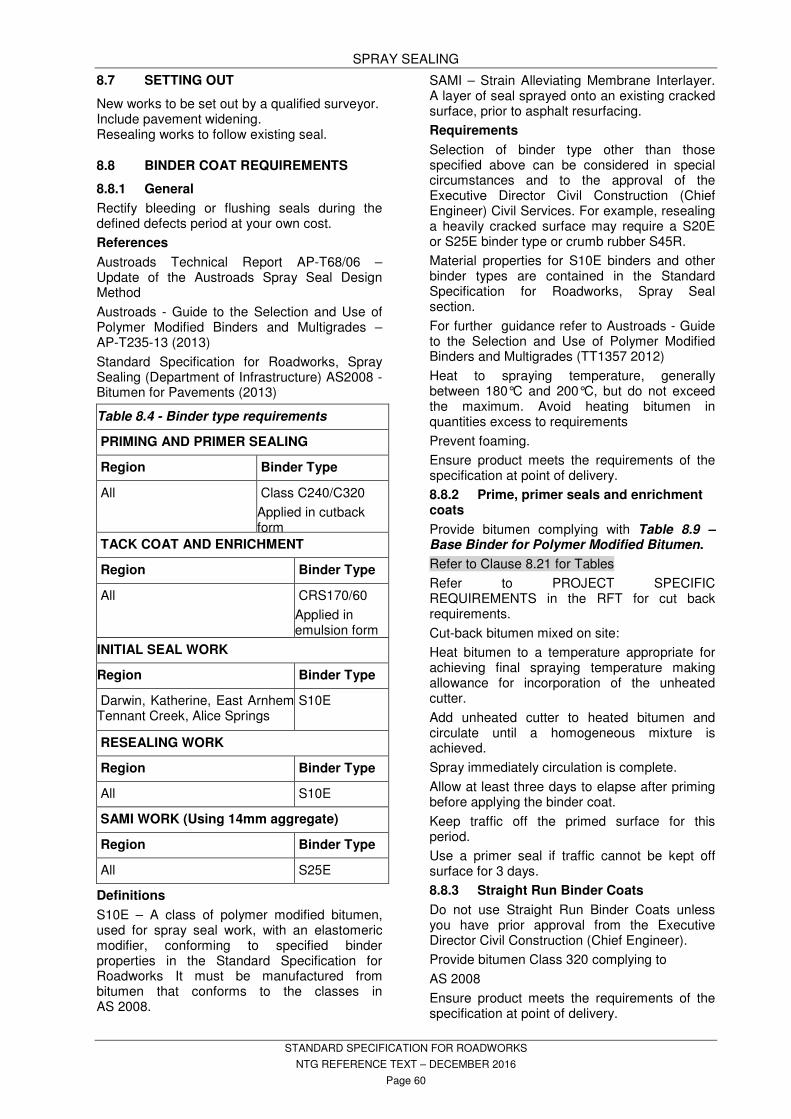
SPRAY SEALING
STANDARD SPECIFICATION FOR ROADWORKS
NTG REFERENCE TEXT – DECEMBER 2016
Page 60
8.7 SETTING OUT
New works to be set out by a qualified surveyor. Include pavement widening. Resealing works to follow existing seal.
8.8 BINDER COAT REQUIREMENTS
8.8.1 General
Rectify bleeding or flushing seals during the defined defects period at your own cost.
References
Austroads Technical Report AP-T68/06 – Update of the Austroads Spray Seal Design Method
Austroads - Guide to the Selection and Use of Polymer Modified Binders and Multigrades – AP-T235-13 (2013)
Standard Specification for Roadworks, Spray Sealing (Department of Infrastructure) AS2008 - Bitumen for Pavements (2013)
Table 8.4 - Binder type requirements
PRIMING AND PRIMER SEALING
Region Binder Type
All Class C240/C320
Applied in cutback form
TACK COAT AND ENRICHMENT
Region Binder Type
All CRS170/60
Applied in emulsion form
INITIAL SEAL WORK
Region Binder Type
Darwin, Katherine, East Arnhem Tennant Creek, Alice Springs
S10E
RESEALING WORK
Region Binder Type
All S10E
SAMI WORK (Using 14mm aggregate)
Region Binder Type
All S25E
Definitions
S10E – A class of polymer modified bitumen, used for spray seal work, with an elastomeric modifier, conforming to specified binder properties in the Standard Specification for Roadworks It must be manufactured from bitumen that conforms to the classes in AS 2008.
SAMI – Strain Alleviating Membrane Interlayer. A layer of seal sprayed onto an existing cracked surface, prior to asphalt resurfacing.
Requirements
Selection of binder type other than those specified above can be considered in special circumstances and to the approval of the Executive Director Civil Construction (Chief Engineer) Civil Services. For example, resealing a heavily cracked surface may require a S20E or S25E binder type or crumb rubber S45R.
Material properties for S10E binders and other binder types are contained in the Standard Specification for Roadworks, Spray Seal section.
For further guidance refer to Austroads - Guide to the Selection and Use of Polymer Modified Binders and Multigrades (TT1357 2012)
Heat to spraying temperature, generally between 180°C and 200°C, but do not exceed the maximum. Avoid heating bitumen in quantities excess to requirements
Prevent foaming.
Ensure product meets the requirements of the specification at point of delivery.
8.8.2 Prime, primer seals and enrichment coats
Provide bitumen complying with Table 8.9 – Base Binder for Polymer Modified Bitumen.
Refer to Clause 8.21 for Tables
Refer to PROJECT SPECIFIC REQUIREMENTS in the RFT for cut back requirements.
Cut-back bitumen mixed on site:
Heat bitumen to a temperature appropriate for achieving final spraying temperature making allowance for incorporation of the unheated cutter.
Add unheated cutter to heated bitumen and circulate until a homogeneous mixture is achieved.
Spray immediately circulation is complete.
Allow at least three days to elapse after priming before applying the binder coat.
Keep traffic off the primed surface for this period.
Use a primer seal if traffic cannot be kept off surface for 3 days.
8.8.3 Straight Run Binder Coats
Do not use Straight Run Binder Coats unless you have prior approval from the Executive Director Civil Construction (Chief Engineer).
Provide bitumen Class 320 complying to
AS 2008
Ensure product meets the requirements of the specification at point of delivery.
SPRAY SEALING
STANDARD SPECIFICATION FOR ROADWORKS
NTG REFERENCE TEXT – DECEMBER 2016
Page 61
8.8.4 Polymer Modified Binder Coats
Provide bitumen in conformance with Table 8.9 – Base Binder for Polymer Modified Bitumen blended with the required polymer as follows:
Prepare the product in a manufacturing or blending plant that complies with the Guide to the Manufacture, Storage and Handling of Polymer Modified Binders, Australian Asphalt Pavement Association, 2013.
Refer to Clause 8.21 for Tables
Refer to PROJECT SPECIFIC REQUIREMENTS in the RFT for Initial seal coat Class and Reseal coat Class.
Ensure product meets the requirements of the specification at point of delivery.
Store, mix, heat and spray the polymer modified binder as recommended by the polymer manufacturer.
Both coats of two coat seals shall contain polymer.
− Initial seal coat: Class S10E
− Reseal coat: Class S10E
8.8.5 Binder Coats, Tender Quantities
Refer to PROJECT SPECIFIC REQUIREMENTS in the RFT for spray rates used as a basis for calculating tender quantities.
8.9 SAMPLING OF BINDER
8.9.1 Test Request
Darwin Urban areas – Test requests are to be sent to the panel period contractor to witness sampling and arrange testing.
All other areas - the supplier is to sample and deliver the sample to Departmental staff within 48 hours.
8.9.2 Supply of Sampling Containers
Supply all sampling containers as required for sampling purposes.
- Sample containers are to be leak proof and having a capacity of not less than one litre.
- Sample containers must be clean, rust free and capable of receiving a product at high temperatures.
8.9.3 Definition of Sampling - A sample is three containers of product
collected at the same time from the same supply source.
- One sample container is for the Contractor’s analysis.
- Two sample containers are for the Department to analyse.
Note: Refer to the Superintendent for requirements if samples are non-conforming
8.9.4 Frequency of Samples
Refer to CONFORMANCE TESTING.
8.9.5 Collection of Samples – WITNESS POINT
Take samples prior to addition of adhesion agents.
Conformance test sampling is to be collected at point of delivery.
Ensure bulkers and road tankers have adequate sampling cocks installed so as samples can be taken on transfer from the bulker to the sprayer. Do not take bituminous samples from the spray wagon, except for prime samples.
Witness Point – Take samples from the point of delivery on transfer from the bulker to the sprayer or as directed. Where transfer is for works in the urban area or for small works ensure that conformance testing is ordered and samples are taken at the point of transfer from bulker to sprayer.
All sampling must be in accordance with Australian or Austroads standards. The supplier is to perform the sampling. Ensure staff carrying out sampling are competent in sampling methods.
Ensure sampling techniques do not allow contamination of the samples.
Where samples are not collected, 10% reduction adjustments (Table 23.1 – Payment Adjustments in MEASUREMENT AND PAYMENT) will apply to the total materials represented.
8.9.6 Sample Identification
Samples must be clearly identified with permanent marker on adhesive labels on each tin.
Mark samples with the following information on the container at the time of collection.
- Container number.
- Sample number.
- Date and time of sample taken.
- Designation or Classification of Materials.
- Sample Temperature.
- Tanker/Sprayer Identification Number.
- Name of Supplier.
- Road Name and number.
- Site Identification.
- Location and Chainage.
Reseals - Maintain an electronic register of all samples which includes the information listed above. Provide a copy of this register to the Superintendent on request.
8.9.7 Storage and Delivery of Samples
Store all samples taken to prevent accidental damage or contamination. Submit sample containers at the completion of each days spraying.

SPRAY SEALING
STANDARD SPECIFICATION FOR ROADWORKS
NTG REFERENCE TEXT – DECEMBER 2016
Page 62
8.10 STOCKPILE SITES
8.10.1 Stockpiles of materials
Stockpiles in urban areas are not permitted.
Urban areas for Darwin region is nominated as – North of Cox Peninsula Road (Stuart Highway), West of Trippe Road (Arnhem Highway) and the end of seal on Gunn Point Road.
Other urban areas are nominated as being within, and extending to, town boundaries.
Existing stockpile sites – clean to suit.
Provide a separate site for each aggregate size. Allow 15 metres between adjacent sites.
Ensure sites are well drained and on hard ground. Avoid contamination by dust.
Maintain access roads and stockpile sites.
Do not allow stockpiled aggregates to become wet due to rain. Cover all stockpiles with sheet plastic or similar material.
Avoid sites under trees, telephone lines, overhead transmission lines or where overhead clearance is less than 6 metres.
Clear all vegetation within the existing stockpile boundary only.
Remove from site any non-conforming aggregate.
For work in or close to regional centres, towns and urban areas (50 km), remove all unused aggregate from stockpile sites at conclusion of work.
For rural work, prepare unused aggregate into one neat and tidy stockpile, per aggregate size. Aggregate remaining in stockpiled areas becomes property of the Northern Territory Government at Practical Completion stage.
Neatly stockpile all waste materials from the screening process.
8.11 PRECOATING AGGREGATE
All aggregates used must be dry before precoating.
No precoat is required for SAMI and Emulsion seals, unless stated in the response schedules.
Apply a uniform film of precoating material to the all aggregate used for sealing purposes.
Aggregate which has been excessively precoated will be rejected.
Precoating is to take place at pre-approved site stockpile locations unless otherwise approved by the Superintendent.
All precoating must be performed with a powered shaking screen deck precoater, which removes dust, dirt and oversize materials and evenly applies precoat to the aggregate.
8.12 ADHESION AGENT
Adhesion agent must be used. Do not use diesel based adhesion agents.
Use 1% adhesion agent in the binder. Written Superintendent approval must be obtained for variation of this rate.
Circulate in binder for 20 minutes before spraying.
Provide the Superintendent a copy of the Safety Data Sheet information of the adhesion agent prior to its intended use.
8.13 SPRAYING – WITNESS POINT
Witness Point - Give the Superintendent 48 hours notice of intention to spray bitumen.
Store bitumen at lowest practical temperature and for the shortest possible duration.
Comply with Table 8.5 – Temperature Control Requirements for Polymer Modified Binders.
Seek approval to vary these requirements.
Remove bitumen from the site when temperature limits are exceeded.
8.13.1 Atmospheric Conditions
Commence spraying only when pavement temperature
- is in excess of 20 °C , or
- has been in excess of 15 °C for at least one hour.
For cutback work, commence spraying when pavement temperature is in excess of 10 °C .
For emulsion work, commence spraying when pavement temperature is in excess of 5 °C .
Cease spraying if rain threatens, or in windy or dusty conditions.
Table 8.5 – Temperature Control Requirements for Polymer Modified Binders
Property Straight Run Binder
Polymer Modified Binder
Temperature at point of spraying
175 to 185 °C 180 to 200 °C
Holding time at spraying temperature
7 days max, 2 days max.
Temperature for medium term storage
130 to 150 °C 140 to 160 °C
Holding time for medium term storage
30 days 7 to 10 days
SPRAY SEALING
STANDARD SPECIFICATION FOR ROADWORKS
NTG REFERENCE TEXT – DECEMBER 2016
Page 63
Protect the work in the event of a sudden change in weather by closing the affected section of road or by rigidly controlling traffic speed.
8.13.2 Preparing the Sprayer
Circulate the mixture.
Check the horizontal and vertical alignment and the cleanliness of the spraybar and its extensions.
Determine the appropriate number of nozzles for the width to be sprayed. Ensure the end nozzles fitted are EAN18W.
Check that the nozzles in use are symmetrical about the sprayer.
Check the alignment and setting of the nozzle to ensure that the fans of material from intermediate nozzles are parallel and at an angle of 30 deg. to the centre line of the spraybar. Ensure that the fans from the end nozzles are parallel to each other and at an angle of 45 degrees to the centre line of the spraybar.
Set the height of the spraybar so that the lower faces of the nozzles are 250 mm (or that specified on the calibration certificate) above the pavement when the sprayer is full.
Fit an end shield to the spraybar when necessary to prevent spraying material on the kerb, or to counter any wind effects which would compromise uniform spraying.
Position the guide rod to conform to the setting out and edges of spray. Check by making a dummy run.
8.13.3 Application Spray Rates – Hold Point
Application spray rates shall be determined by the Superintendent, using appropriate Austroads design methods.
For new seals and reseals, supply the following to the Superintendent, 3 working days prior to the planned commencement of sealing, to allow the spray rates to be calculated:
- Particle Size Distribution (1 per 250 tonne - minimum 3 tests)
- Average Least Dimension (ALD) (1 per 250 tonne - minimum 3 tests)
- Flakiness Index (FI) of the aggregate, (1 per 250 tonne - minimum 3 tests)
- Ball Penetration testing (for new seal work)
- Dryback results (for new seal work)
Refer to Conformance Testing for sampling requirements of aggregates.
Hold Point – Do not commence spraying until the spray rates are advised by the Superintendent.
Spray rates to be at 15°C adjusted in accordance with Table 23.2 – Bitumen Equivalent Volumes.
For primers, primer seals and polymer modified binders, the rate of application refers to the whole of the mixture, including all modifiers, cutback materials, combining oils and adhesion agents. For enrichments and emulsion seals, the rate of application refers to the whole of the mixture.
8.13.4 Preparation for Sprayer Run – Witness Point
Record the volume and temperature of the sprayer contents while it is on level ground.
Supply Sprayer Tank dips before and after each sprayer run.
Witness Point - Allow visual inspection when requested.
Determine the length of sprayer run from the available quantity in the sprayer and the application rate. Ensure the area to be sprayed is not greater than the area that can be covered by aggregate in the loaded trucks.
Start and finish each spray run on a protective strip of paper placed on the pavement. The paper to be wide enough to ensure the sprayed material is being discharged correctly over the full width of spray. Place sufficient protective paper to protect road fixtures.
Place paper on the pavement and masking around areas to be sprayed or wherever the sprayer is stationary on the road pavement.
Seal joins are only allowed where linemarking is to be placed. No joins are allowed in wheel paths.
Excess overspray and spills must be removed before sealing works proceed.
8.13.5 Installation of Temporary Pavement Markers
Temporary Pavement Markers to conform to AS 1906.3.
Spacings of temporary pavement markers to be in accordance with AS 1742.3 or as directed by the Superintendent.
8.13.6 Sprayer Run
Attain uniform spraying speed before spraying commences.
Avoid an excess or deficiency of material due to faulty overlap at longitudinal joints when spraying a road in half-widths.
Overlap to be 300 mm with an intermediate nozzle.
Do not use end nozzles on an overlap.
Make allowances for “Fog Spraying” when joining to existing seals.

SPRAY SEALING
STANDARD SPECIFICATION FOR ROADWORKS
NTG REFERENCE TEXT – DECEMBER 2016
Page 64
Cease spraying before the level of material in the tank falls to a level which reduces the full discharge of the pump.
Remove and dispose of all paper as per the Environmental Management Plan.
Clean off any sprayed material from road fixtures.
8.13.7 Hand Spraying
Plan work to minimise the requirement for the use of a hand sprayer.
Any strips of pavement not adequately covered with sprayed material to be sprayed later with the hand attachment.
8.14 APPLICATION OF GEOFABRIC – HOLD POINT
Hold Point - Submit details of proposed machinery and method of application.
Overlap longitudinal and transverse joints 150 mm minimum.
Place longitudinal joints in the fabric along lane boundaries within 100 mm of lane marker. Trim the fabric as required to achieve this.
Bond the fabric to the pavement with a tack coat sprayed 100 mm wider than the fabric and in accordance with the Superintendent’s directions for location. Use Standard Bitumen class C320 for the tack coat.
Place the fabric under tension when laying, using suitable machinery, ensuring that folds or creases do not occur. Use equipment to place fabric that does not cause undue migration of the underlying tack coat into the fabric.
Upon completion of placing of fabric and prior to application of the second/top binder coat, roll the fabric with minimum 4 passes of a pneumatic multi-wheel roller. Carry out rolling of the geofabric at a constant roller velocity with no acceleration or deceleration.
Use Standard Class C320 binder for the second / top binder coats.
8.15 APPLICATION OF AGGREGATE – HOLD POINT
Load aggregate into appropriate aggregate spreading trucks using an approved loader which does not contaminate the aggregate with dust, dirt and oversize stone while applying pre-coat.
Hold Point – Obtain approval from the Superintendent for use of the proposed aggregate loader before commencing loading operations.
Apply aggregate to sprayed binder within:
- 10 minutes where the pavement temperature is 20°C or greater.
- 5 minutes where the pavement temperature is between 15 and 20 °C .
Polymer Modified Binders: Apply aggregate within 5 minutes irrespective of pavement temperature.
Apply aggregate to emulsion coat before the emulsion breaks.
Use “cut off plates” on spreader boxes to ensure that the correct widths are covered in aggregate, without overlap.
In trafficked areas, apply both coats of a two coat seal on the same day. Where not trafficked apply the second coat on the following day.
8.15.1 Aggregate Spread Rates
Spread the aggregate evenly and uniformly over the sprayed surface at a rate complying with Table 8.6 – Aggregate Spread Rates.
Use a mechanical spreader, manual spreader boxes are not to be used.
Rerun or hand cover bare or insufficiently covered areas after the first spreading.
Remove all excess aggregate.
8.15.2 Rolling Rate
Roll the treated surface with self-propelled rubber tyred rollers with a minimum tyre pressure of 600 kPa and a minimum wheel load of 1 tonne.
Roller speed on the first pass to be between 5 and 10km/h, with subsequent passes between 15 and 25 km/h.
Conform to the following:
- Entire area to receive one roller pass immediately after covering.
- 75% of rolling within 1 hour of covering.
- 100% of rolling within 2 hours of covering.
Minimum Rolling Rate: 1 roller hour per 2,000 litres of binder.
Ensure a uniform distribution of aggregate. Drag broom to distribute surplus aggregate but do not dislodge embedded aggregate. Drag broom before 50% of rolling is complete. Drag brooms are not to be rotary brooms.
For two coat treatments, double the specified rolling rate if the second coat is to be applied immediately or the surface is not to be trafficked.
Roll in daylight hours only.
Sweep all loose aggregate from the carriageway at completion of rolling.
Ensure aggregate on the final surface is uniformly distributed and firmly held by the binder.
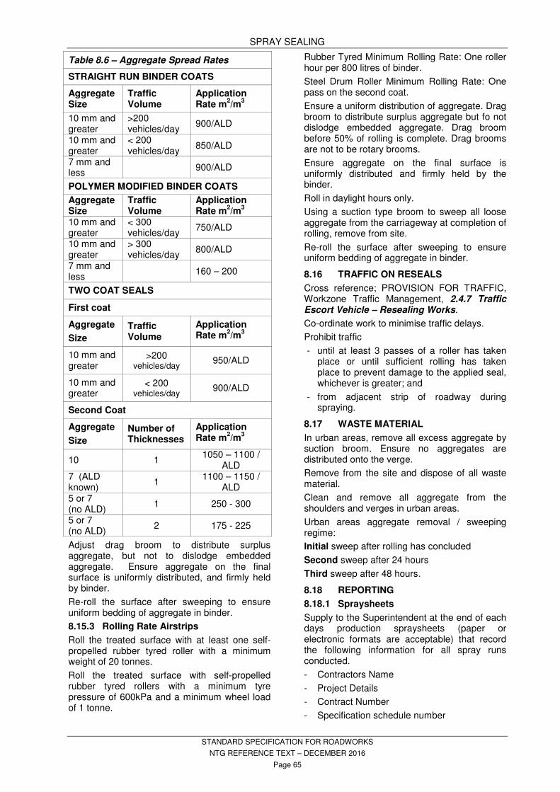
SPRAY SEALING
STANDARD SPECIFICATION FOR ROADWORKS
NTG REFERENCE TEXT – DECEMBER 2016
Page 65
Table 8.6 – Aggregate Spread Rates
STRAIGHT RUN BINDER COATS
Aggregate Size
Traffic Volume
Application Rate m
2/m
3
10 mm and greater
>200 vehicles/day
900/ALD
10 mm and greater
< 200 vehicles/day
850/ALD
7 mm and less
900/ALD
POLYMER MODIFIED BINDER COATS
Aggregate Size
Traffic Volume
Application Rate m
2/m
3
10 mm and greater
< 300 vehicles/day
750/ALD
10 mm and greater
> 300 vehicles/day
800/ALD
7 mm and less
160 – 200
TWO COAT SEALS
First coat
Aggregate
Size
Traffic Volume
Application Rate m
2/m
3
10 mm and greater
>200 vehicles/day
950/ALD
10 mm and greater
< 200 vehicles/day
900/ALD
Second Coat
Aggregate
Size
Number of Thicknesses
Application Rate m
2/m
3
10 1 1050 – 1100 /
ALD 7 (ALD known)
1 1100 – 1150 /
ALD 5 or 7 (no ALD)
1 250 - 300
5 or 7 (no ALD)
2 175 - 225
Adjust drag broom to distribute surplus aggregate, but not to dislodge embedded aggregate. Ensure aggregate on the final surface is uniformly distributed, and firmly held by binder.
Re-roll the surface after sweeping to ensure uniform bedding of aggregate in binder.
8.15.3 Rolling Rate Airstrips
Roll the treated surface with at least one self-propelled rubber tyred roller with a minimum weight of 20 tonnes.
Roll the treated surface with self-propelled rubber tyred rollers with a minimum tyre pressure of 600kPa and a minimum wheel load of 1 tonne.
Rubber Tyred Minimum Rolling Rate: One roller hour per 800 litres of binder.
Steel Drum Roller Minimum Rolling Rate: One pass on the second coat.
Ensure a uniform distribution of aggregate. Drag broom to distribute surplus aggregate but fo not dislodge embedded aggregate. Drag broom before 50% of rolling is complete. Drag brooms are not to be rotary brooms.
Ensure aggregate on the final surface is uniformly distributed and firmly held by the binder.
Roll in daylight hours only.
Using a suction type broom to sweep all loose aggregate from the carriageway at completion of rolling, remove from site.
Re-roll the surface after sweeping to ensure uniform bedding of aggregate in binder.
8.16 TRAFFIC ON RESEALS
Cross reference; PROVISION FOR TRAFFIC, Workzone Traffic Management, 2.4.7 Traffic Escort Vehicle – Resealing Works.
Co-ordinate work to minimise traffic delays.
Prohibit traffic
- until at least 3 passes of a roller has taken place or until sufficient rolling has taken place to prevent damage to the applied seal, whichever is greater; and
- from adjacent strip of roadway during spraying.
8.17 WASTE MATERIAL
In urban areas, remove all excess aggregate by suction broom. Ensure no aggregates are distributed onto the verge.
Remove from the site and dispose of all waste material.
Clean and remove all aggregate from the shoulders and verges in urban areas.
Urban areas aggregate removal / sweeping regime:
Initial sweep after rolling has concluded
Second sweep after 24 hours
Third sweep after 48 hours.
8.18 REPORTING
8.18.1 Spraysheets
Supply to the Superintendent at the end of each days production spraysheets (paper or electronic formats are acceptable) that record the following information for all spray runs conducted.
- Contractors Name
- Project Details
- Contract Number
- Specification schedule number

SPRAY SEALING
STANDARD SPECIFICATION FOR ROADWORKS
NTG REFERENCE TEXT – DECEMBER 2016
Page 66
- Road Name
- Product Type Sprayed
- Precoat type used, Precoat litres / m3
- Aggregate supplier, Aggregate Type, Aggregate size
- Run number, Start Time of spray run
- Pavement Temperature, Ambient Temperature
- Start Chainage of spray run – actual km of road
- End chainage of spray run – actual km of road
- Total Length, Width of spray run
- Total area of spray run
- Temperature of product at spraying
- Start Dip, End Dip
- Total sprayed hot, Correction factor, Total sprayed cold
- Application rate cold
- Ordered application rate
- Percent of application rate ordered
- Number of rollers used
- Bitumen sample number
- Signature of contractor representative
- Signature section for client representative
8.19 CONFORMANCE - TOLERANCES
Final surfaces shall conform to the following:
Aggregates are to conform to Table 8.8 – Aggregate Properties.
Refer to Clause 8.21 for Tables
Skid Resistance determined by NTTM 304.1.
Skid resistance testing may be carried out by the Superintendent.
Final surfaces with non-conforming skid resistance will be rejected.
Rectify non-conforming work by methods approved by the Superintendent. Rectification work be at the Contractor’s expense, including the cost of testing.
Remove from the site binder which has been overheated or has deteriorated or become contaminated prior to its application to the road.
Spray rates applied at less than 95% or more than 105% of the rate indicated in the procedure will be rectified by resurfacing at the contractors expense inclusive of all materials.
8.20 ADJUSTMENT TO VOLUMES FOR SPRAY RATES
This includes the prime coat, enrichment coat, emulsion coat, primerseal and seal coats.
Refer to MEASURMENT AND PAYMENT for schedules of adjustments.
8.21 TABLES
Table 8.7 – Aggregate Grading and Average Least Dimension (ALD)
Sieve Size (mm)
% Passing (Dry Mass)
Nominal Size of Aggregate
20 mm 16 mm 14 mm 10 mm 7 mm 5 mm
26.5 100
19.0 85 - 100 100
16.0 - 80 - 100 100
13.2 0 - 15 0 – 20 85 - 100 100
9.5 0 - 5 0 – 2 0 - 15 85 - 100 100
6.7 0 - 2 0 - 5 0 - 15 85 - 100 100
4.75 0 - 2 0 - 5 0 - 15 85 - 100
2.36 0 - 2 0 - 5 0 - 15
1.18 0 - 2 0 - 5
Min. ALD (1) 12.0mm 9.5mm 8.0mm 5.5mm 3.5mm 2.5mm
Note: (1). Test Methods AS 1141.20.1, AS 1141.20.2 - Direct Measurement.

SPRAY SEALING
STANDARD SPECIFICATION FOR ROADWORKS
NTG REFERENCE TEXT – DECEMBER 2016
Page 67
Table 8.8 – Aggregate Properties
Aggregate Property
Traffic Count (AADT: Two Lanes)
Less Than 300 VPD
300 to 6,000 VPD
More Than 6,000 VPD
AS 1141.14 Misshapen Particles: Calliper Ratio 2:1 25% maximum 15% maximum 12% maximum
AS 1141.15 Flakiness Index 35 maximum 30 maximum 25 maximum
AS 1141.23 Los Angeles Abrasion (LAA):
- Fine Grained Aggregate 30% maximum 25% maximum 20% maximum
- Coarse Grained Aggregate 40% maximum 35% maximum 30% maximum
AS 1141.24 Sulphate Soundness 15% maximum 12% maximum 10% maximum
AS 1141.40/41 Polished Aggregate Friction Value 40 minimum 40 minimum 45 minimum
AADT - Annual Average Daily Traffic; VPD - Vehicles Per Day AS 1141.18 - Crushed particles in coarse aggregate derived from gravel. Ensure 80% minimum by
mass are classified as crushed particles. AS 1141.25.1 - Degradation factor – Source rock (Washington Degradation Test). Igneous rocks shall
have a minimum value of 50. AS 1141.26 - Secondary minerals content in igneous rocks shall not exceed 25%. AS 1141.29 - Accelerated soundness index by reflux. Igneous rocks shall have a minimum value of 94. AS 1141.50 - Resistance to stripping of cover aggregates from binders. The maximum stripping value of
precoated aggregate (precoat shall contain 1% adhesion agent.) shall be 10%.
Table 8.9 – Base Binder for Polymer Modified Bitumen
Property Specification limit
minimum
Specification limit
maximum
Viscosity at 60oC, Pa.s 140 380
Viscosity at 135oC, Pa.s 0.25 0.65
Penetration at 25oC (100g, 5s),pu (pu unit is
0.1mm) 40
Flashpoint oC 250 N/A
Matter Insoluble in toluene, percent mass N/A 1.0
Short Term effect of heat and air
(Rolling Thin film Oven Test)
Viscosity of residue at 60oC as a
percentage of original
N/A
300
Long term effect of Heat and air, days 7
Density at 15oC, t/m
3 TBR
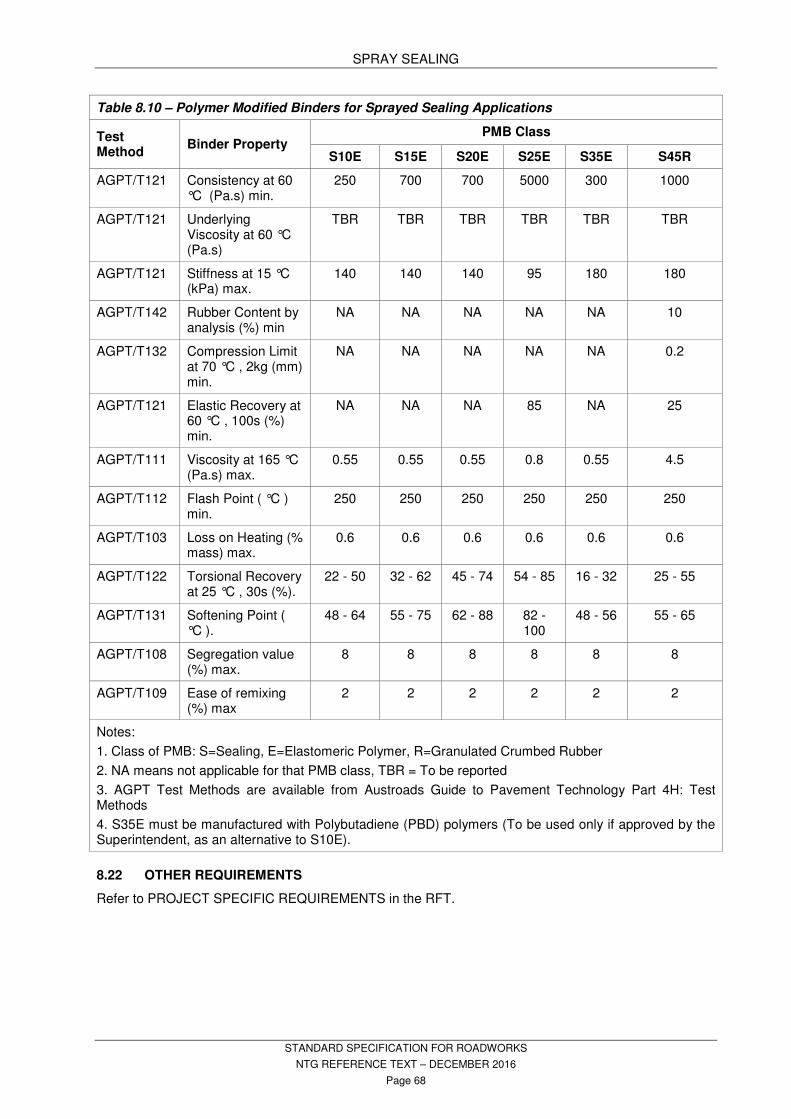
SPRAY SEALING
STANDARD SPECIFICATION FOR ROADWORKS
NTG REFERENCE TEXT – DECEMBER 2016
Page 68
Table 8.10 – Polymer Modified Binders for Sprayed Sealing Applications
Test Method
Binder Property PMB Class
S10E S15E S20E S25E S35E S45R
AGPT/T121 Consistency at 60 °C (Pa.s) min.
250 700 700 5000 300 1000
AGPT/T121 Underlying Viscosity at 60 °C (Pa.s)
TBR TBR TBR TBR TBR TBR
AGPT/T121 Stiffness at 15 °C (kPa) max.
140 140 140 95 180 180
AGPT/T142 Rubber Content by analysis (%) min
NA NA NA NA NA 10
AGPT/T132 Compression Limit at 70 °C , 2kg (mm) min.
NA NA NA NA NA 0.2
AGPT/T121 Elastic Recovery at 60 °C , 100s (%) min.
NA NA NA 85 NA 25
AGPT/T111 Viscosity at 165 °C (Pa.s) max.
0.55 0.55 0.55 0.8 0.55 4.5
AGPT/T112 Flash Point ( °C ) min.
250 250 250 250 250 250
AGPT/T103 Loss on Heating (% mass) max.
0.6 0.6 0.6 0.6 0.6 0.6
AGPT/T122 Torsional Recovery at 25 °C , 30s (%).
22 - 50 32 - 62 45 - 74 54 - 85 16 - 32 25 - 55
AGPT/T131 Softening Point ( °C ).
48 - 64 55 - 75 62 - 88 82 - 100
48 - 56 55 - 65
AGPT/T108 Segregation value (%) max.
8 8 8 8 8 8
AGPT/T109 Ease of remixing (%) max
2 2 2 2 2 2
Notes:
1. Class of PMB: S=Sealing, E=Elastomeric Polymer, R=Granulated Crumbed Rubber
2. NA means not applicable for that PMB class, TBR = To be reported
3. AGPT Test Methods are available from Austroads Guide to Pavement Technology Part 4H: Test Methods
4. S35E must be manufactured with Polybutadiene (PBD) polymers (To be used only if approved by the Superintendent, as an alternative to S10E).
8.22 OTHER REQUIREMENTS
Refer to PROJECT SPECIFIC REQUIREMENTS in the RFT.

DENSE GRADED ASPHALT
STANDARD SPECIFICATION FOR ROADWORKS
NTG REFERENCE TEXT – DECEMBER 2016
Page 69
9. DENSE GRADED ASPHALT
9.1 CONTRACTORS RESPONSIBILITIES
The Contractor is responsible for the production and placing of the registered and approved design mix in accordance with the technical requirements of this specification.
The Contractor must undertake conformance testing in accordance with CONFORMANCE TESTING and maintain a record of test results in accordance with the Contractor’s Quality System.
9.2 STANDARDS
Conform to the following Standards and Publications unless specified otherwise:
AS 1141 (set) Methods for sampling and testing aggregate.
AS 1160 Bituminous emulsion for the construction and maintenance of pavements.
AS 2008 Bitumen for pavements.
AS 2150 Hot mix asphalt – a guide to good practice.
AS 2157 Cut back bitumen.
AS 2758 (set) Aggregates and rock for engineering purposes.
AS 2891 (set) Methods of sampling and testing asphalt.
AUSTRALIAN ASPHALT PAVEMENT ASSOCIATION (AAPA)
Guide to the manufacture, storage and handling of polymer modified binders (Available via http://www.aapa.asn.au/documents/item/308 ) Advisory Note 7 Guide to the manufacture, storage and handling of binders for spray sealing (and hot mix asphalt) (available via http://www.aapa.asn.au/technology-and-publications/advisory-notes )
AUSTROADS
AGPT04B Austroads Guide to Pavement Technology Part 4B Asphalt
AGPT04H Austroads Guide to Pavement Technology Part 4H: Test Methods
AGPT/T103 Pre-treatment and Loss on Heating of Bitumen Multigrade and polymer Binders (rolling thin film oven [RTFO] test)
AGPT/T111 Handling Viscosity of Polymer Modified Binders (Brookfield Thermosel)
AGPT/T112 Flash Point of Polymer Modified Binders
AGPT/T121 Shear Properties of Polymer Modified Binders (ARRB ELASTOMETER)
AGPT/T122 Torsional Recovery of Polymer Modified Binders
AGPT/T131 Softening Point of Polymer Modified Binders
AGPT/T190 Austroads Framework Specification for Polymer Modified Binders and Multigrade Bitumen
NT PUBLICATIONS
NTCP 103.1 Site selection by the stratified random technique
NTCP 107.1 Ride Quality
NTMTM Northern Territory Materials Testing Manual – available at
https://infrastructure.nt.gov.au/technical-information
NTTM Northern Territory Test Method
OTHER PUBLICATIONS
MRWA Main Roads Western Australia, Test Methods
9.3 DEFINITIONS
COARSE GRAINED AGGREGATE:
Where the average grain size of the constituent minerals is greater than 5 mm. The average grain size is determined optically under a petrographic microscope.
FINE GRAINED AGGREGATE:
Where the average grain size of the constituent minerals is less than 5 mm. The average grain size is determined optically under a petrographic microscope.
IRI International Roughness Index (IRIqc)
JOB MIX:
Adjusted blend composition of registered mix design based on production trial.
NTCP Northern Territory Code of Practice
NTMTM Northern Territory Materials Testing Manual – available via https://infrastructure.nt.gov.au/technical-information
NTTM Northern Territory Test Method
RAP Reclaimed Asphalt Pavement
REGISTERED MIX DESIGN:
An asphalt mix which has been placed on the Department’s Asphalt Mix Design Register and approved for use by the Superintendent.
VLD Vehicles per lane per day
DENSE GRADED ASPHALT
STANDARD SPECIFICATION FOR ROADWORKS
NTG REFERENCE TEXT – DECEMBER 2016
Page 70
WARM MIX ASPHALT:
Warm Mix Asphalt (WMA)” is asphalt that contains a warm mix additive, or utilises a warm mix process, that has the ability to reduce the mixing and compaction temperature requirements below the typical temperatures used for that application.
9.4 TRAFFIC CATEGORIES
Unless specified otherwise, the traffic categories shown in Table 9.1 - Mix Type and Binder Type for Traffic Categories and the mix types shown in Table 9.2 - Mix type designations shall be used to determine the required mix design level and binder type.
Refer to Clause 9.13 for Tables
Urban areas are defined as follows:
− Darwin region urban area is nominated as North of Cox Peninsular Road (Stuart Highway), west of Trippe Road (Arnhem Highway) and the end of seal on Gunn Point Road
− Katherine, Tennant Creek and Alice Springs urban areas are defined as the areas within the respective town boundaries.
9.5 MATERIALS
9.5.1 Coarse Aggregates
Coarse aggregates must consist of crushed stone, with a minimum of 3 crushed faces, which is clean, hard, of high strength, angular, which has adequate skid resistance, which is durable and free from laminated particles, clay and other aggregations of fine material, soil, organic matter and any other deleterious material. Coarse aggregate must not fracture under compaction equipment or deteriorate rapidly. Coarse aggregate materials must conform to the requirements of Table 9.3 - Properties - Coarse Aggregates:
Refer to Clause 9.13 for Tables
9.5.2 Fine Aggregates
Fine aggregates must consist of clean, hard, sharp, washed, durable natural sand and/or material manufactured from crushed stone of uniform quality free from clay and other aggregations of fine material, soil, organic matter and any other deleterious material.
Where crushed fine materials are from sources other than the source of the coarse material used in the asphalt mix, the parent rock must meet all requirements listed in Table 9.3 - Properties - Coarse Aggregates.
Fine aggregates must meet the requirements of Table 9.4 - Properties - Fine Aggregate.
Refer to Clause 9.13 for Tables
9.5.3 Mineral Filler
Filler must consist of mineral material consisting of natural or crushed mineral materials, hydrated lime or cement with a particle size less than 0.075 mm.
Filler must be dry, free from lumps, clay, organic material or any other deleterious material, and complies in all respects with the requirements of AS 2150.
9.5.4 Bituminous Binder - Witness Point
Refined bitumen must be Class 320, conforming to the requirements of AS 2008.
Polymer Modified Binders (PMB) must comply to the requirements of Austroads Framework Specification for Polymer Modified Binders and Multigrade Bitumen, AGPT/T190. Properties of PMB grades referred to in this specification are outlined in Error! Reference source not found..
Refer to Clause 9.13 for Tables
Bitumen handling and storage must be in accordance with AAPA Guide to the manufacture, storage and handling of polymer modified binders and with AAPA Advisory Note 7 Guide to the manufacture, storage and handling of binders for spray sealing (and hot mix asphalt).
Witness Point - Demonstrate that the binder used for asphalt manufacture has been handled according to these requirements.
9.5.5 Bitumen Emulsion
A rapid setting bitumen emulsion, conforming to requirements of AS 1160 when applied as a tack coat.
9.5.6 Additives
Additives such as bitumen adhesion agents, hydrated lime and the like may be proposed to be used in the mix, provided that full details of the type of additive are provided. The material must be nominated and shown as part of the mix design in accordance with the Asphalt Mix Design clause.
9.5.6 Reclaimed Asphalt Pavement (RAP)
Crush and screen RAP from milling or excavation of existing asphalt pavements. It must be well graded, free flowing and have a consistent grading and bitumen content. The nominal size of the RAP material must not be greater than the maximum size of the manufactured asphalt material to which it is being added.
RAP material must not contain tar binder and must be free of contaminants such as unbound granular base material, concrete, clay, soil, organic matter or any other deleterious material.
Processed RAP material must be placed in separate stockpiles prior to use. Where RAP material has been stockpiled for some time and

DENSE GRADED ASPHALT
STANDARD SPECIFICATION FOR ROADWORKS
NTG REFERENCE TEXT – DECEMBER 2016
Page 71
is no longer in a free-flowing condition, reprocessing must be undertaken to ensure that the material is free flowing at the time of incorporation into the manufacturing of new asphalt materials.
RAP addition in manufactured asphalt must not exceed:
- 15% by mass in base layers; and
- 10% by mass in the wearing coarse.
9.6 ASPHALT MIX DESIGN
9.6.1 Mix Type and Design Traffic Category
Refer to PROJECT SPECIFIC REQUIREMENTS in the RFT for mix type and design traffic category requirements.
9.6.2 Design Mix Requirements – Hold Point
All asphalt mixes proposed for use on Northern Territory Government (NTG) works shall be registered in accordance with the Department’s Code of Practice for Registration of Asphalt Mix Designs.
Hold Point - Asphalt materials must not be used until the mix has been registered and the Superintendent approves the mix for use.
Approval of a registered asphalt mix for use under the Contract does not relieve the contractor from employing suitable manufacturing and handling techniques to ensure performance of the mix. The Contractor must also satisfy all contractual obligations in regards to rectification of defects.
The manufacturer must notify the Superintendent of any proposed changes to the components or proportions of components used in the registered mix.
Hold Point - Where it is proposed to change the source grading or nature of the components or binders, new mix designs must be carried out in accordance with Department’s Code of Practice for Registration of Asphalt Mix Designs.
Registration of mix designs must be renewed every 2 years from the date of acceptance.
If a registered mix has unsatisfactory handling or field performance, the Contractor or Superintendent may request the mix be de-registered.
9.7 SURFACE PREPARATION
9.7.1 New Construction – Witness Point
Witness Point - Give the Superintendent not less than 24 hours notice of the location and scheduled commencement time of surface preparation works for each work program.
The contractor must prepare existing surfaces to ensure that asphalt construction can be completed in accordance with the requirements of this specification. The Contractor must:
- ensure that the surface has been adequately prepared so that the specified asphalt material density can be achieved. If the Contractor suspects that the base layer is inadequate for asphalt construction the Contractor must inform the Superintendent;
- ensure that the surface has been adequately prepared to achieve shape and level requirements where required;
- ensure that the exposed granular base layer is tightly bound and free from vegetation and other foreign matter;
- ensure there are no laminations or false pavements within the exposed surface;
- remove all foreign matter by sweeping or other means; and
- ensure that exposed granular layers have sufficiently dried back to the requirements of the Final Pavement Surface clause in PAVEMENTS AND SHOULDERS prior to the application of the bituminous spray primer seal.
The Contractor must apply a bituminous spray seal prime coat to the exposed granular surface as specified in. SPRAY SEALING.
Refer to PROJECT SPECIFIC REQUIREMENTS for details of the bituminous seal.
Prior to laying base or wearing surface asphalt all depressions greater than 25 mm must be filled with an asphalt correction course layer. Minimum asphalt layer thicknesses must be observed during this procedure.
9.7.2 Resurfacing of Existing Bitumen and Concrete Surfaces
All vegetation and loose and extraneous matter must be removed prior to the application of bituminous resurfacing materials.
Depressions greater than 25 mm must be filled with an asphalt correction course layer. Minimum asphalt layer thicknesses must be observed during this procedure.
9.7.3 Cold Planing
Unless otherwise specified or directed by the Superintendent, cold planing shall be carried out in such a manner as to leave a uniform surface parallel with the specified ultimate finished surface of the pavement.
All loose materials must be removed from the planed surface prior to placing asphalt.
DENSE GRADED ASPHALT
STANDARD SPECIFICATION FOR ROADWORKS
NTG REFERENCE TEXT – DECEMBER 2016
Page 72
Exposed granular materials must be watered, re-compacted to form a tight and hard surface and, where specified, must be primed or resurfaced with a 7 mm emulsion bituminous seal prior to pacing asphalt. The bituminous seal must be supplied and applied in accordance with SPRAY SEALING.
Temporary Works
Where the cold planed surface is to be opened to traffic, the surface must be cleaned of all loose material and both transverse and longitudinal ramps must be installed in accordance with the Temporary Ramps sub-clause in the Spreading clause in this work section or other means to provide for the safe passage of traffic.
Hold Point -This work must be approved by the Superintendent before the section is opened to traffic.
All temporary ramping materials and/or other measures must be removed prior to placing new asphalt.
Shape and Roughness
Where surface shape of an existing pavement is corrected by cold planing, the application of the resurfacing asphalt layer is considered to be new work. For the purposes of measuring ride quality, the asphalt surfacing following correction of surface shape by cold planing will be designated as new work and roughness limits specified in Error! Reference source not found. must be achieved.
Refer to PROJECT SPECIFIC REQUIREMENTS in the RFT for designated areas of cold planing excluded as new work.
9.7.4 Tack Coat
Apply a fine spray of bitumen emulsion lightly and evenly over the whole of the area to be covered with asphalt.
The pavement must be dry and dust free before any application of tack coat.
Apply tack coat by spray bar fitted to mechanical sprayer. Hand spray only in areas where it is impractical to use a spray bar.
Protective splash boards or spray skirts must be used to eliminate over spray beyond the surface where tack coat is being applied.
Application rate of Residual Binder must be between 0.1 – 0.2 litres/square metre unless otherwise directed by the Superintendent.
Allow the tack coat to ‘break' before laying the asphalt.
Clean and tack coat existing surfaces against which new work is to be laid.
Re-apply Tack coat where damaged by construction traffic or weather.
9.8 MIXING
Asphalt materials must be manufactured in a plant capable of consistently producing asphalt that complies with the approved registered mix design. The asphalt material must meet manufacturing temperature requirements out lined in Table 9.6 – Acceptable Temperature Ranges by Materials.
Refer to Clause 9.13 for Tables
9.8.1 Asphalt Material Storage
Asphalt may be stored in hot storage facilities for a period not exceeding 24 hours from the time of manufacture.
9.9 TRANSPORT AND SUPPLY
9.9.1 Transport
Asphalt materials must be transported by trucks with clean trays which permit seamless discharge of the asphalt material to the receiving hopper. All transport vehicles must be free from oil leaks.
The asphalt material must be covered with suitable tarps to reduce the rate of cooling during transport.
Delivery trucks must be fitted with adjustable tailgate(s) to allow control of the mix during discharge into the receiving hopper.
All delivery dockets must provide information that can trace each load to the manufacturing cycle and also point of placement.
Delivery dockets must record:
- Unique Docket Number
- Time of Departure
- Temperature at point of discharge from the manufacturing plant
- Product Type and Bitumen Type
- Mass of Materials – Individual load tonnage and cumulative tonnage
9.9.2 Rate of Supply
The frequency of asphalt material deliveries must be planned to achieve a uniform rate which is in line with the capacity of spreading and compaction processes.
Rate of delivery must allow continuous placing of the asphalt material having regard to;
- the number of haulage vehicles available; and
- the haulage distance to the work site.
Cooling must be minimised by prompt delivery and placement of the asphalt material at the site.

DENSE GRADED ASPHALT
STANDARD SPECIFICATION FOR ROADWORKS
NTG REFERENCE TEXT – DECEMBER 2016
Page 73
9.10 SPREADING
9.10.1 General - Witness Point
Witness Point - Give at least 24 hours notice before commencement of asphalt material spreading.
The asphalt material must be laid at a uniform thickness to the tolerances listed in Error! Reference source not found. The paving operation must be one continuous operation where practical. Where a break in paving occurs due to a planned stop or prolonged delay period a transverse joint must be constructed.
Asphalt that has cooled below acceptable initial rolling temperature(s) must be removed from site and replaced prior to initial rolling.
Asphalt must not be laid when rain is imminent. Paving must cease during heavy or continuous rain, or in wet conditions where the material will not adhere or key to existing surfaces.
Remove from site all rain affected and/or temperature depleted materials.
9.10.2 Mechanical Spreading
The spreading machine must have a capacity of placing not less than 250 tonnes of asphalt material per hour.
Paving machines must be self-propelled and equipped and operated with an electronic levelling apparatus.
Where limited quantities of asphalt are required, or the area to be paved is restricted or of limited width, such as footpaths or parking areas, other spreaders approved by the Superintendent may be used.
9.10.3 Hand Spreading
Hand spreading will be permitted only in locations where spreading with a paving machine is impractical. Hand work may be used to correct localised depressions and/or irregularities.
Spreading of excess material over newly placed asphalt during joint matching is not permitted. All excess material must be removed and discarded from the site. Broadcasting of asphalt over the mat is not permitted at any time.
9.10.4 Laying Pattern - Witness Point
Work must be completed as one continuous operation where practical.
Witness Point - Provide a construction program and paving plan at least 7 working days prior to commencement of works. Paving plans must be confirmed prior to the commencement of each shift.
9.10.5 Construction Joints
Paving plans must detail the construction processes and procedures. Use processes and procedures which minimise longitudinal and transverse construction joints. Longitudinal
joints must be located within the lane line of the pavement or the traffic sump line. Longitudinal joints must not be located under wheel paths.
Construction joints must be minimised within intersections and the braking zones in approaches and acceleration zones of intersections.
Longitudinal joints must be laterally off-set by 100 mm and transverse joints by 500 mm when paving multiple layers.
During paving overlap each adjoining lane by at least 25 mm to form an even transverse surface. Proud asphalt material must be raked back immediately to form a ridge along the top of the joint. Where excess material remains in place, this material must be removed from the joint area prior to compaction rolling. Following rolling the resultant joint must be smooth and of similar texture to the pavement in general.
9.10.6 Transverse Joints
Form transverse joints by cutting with a purpose-built asphalt cut off wheel or diamond saw to form a vertical face. All waste asphalt is to be removed from site.
When constructing transverse joints, ensure that the joint and the approaches to the joint do not deviate more than 5 mm under a 3 metre straight edge. Cut back existing pavement to a true level surface with no deviation. Cut back must be a minimum of 200 mm or be sufficient in length to match existing pavement levels and to also maintain cross falls.
Exposed joint faces must be treated with bitumen emulsion tack coat prior to placing asphalt against them.
Transverse Match of Overlay to Existing Pavement:
Saw cut existing asphalt pavement 20 mm depth along the match line of joint.
Remove taper wedge of existing asphalt pavement along the overlay side of match joint.
Feather the asphalt overlay down to the existing pavement to achieve a maximum slope of 1 in 10 and for the full width of the pavement.
Ensure depth of overlay above existing pavement in taper wedge area is not less than 20 mm.
9.10.7 Longitudinal Joints
All longitudinal joints must be parallel to and follow the shape of the road alignment unless directed otherwise by the Superintendent. Edges must not remain unsupported unless directed otherwise by the Superintendent. Unsupported edges must be cut back at least 75 mm if adjacent runs are not paved within the time taken to cool below acceptable paving

DENSE GRADED ASPHALT
STANDARD SPECIFICATION FOR ROADWORKS
NTG REFERENCE TEXT – DECEMBER 2016
Page 74
temperatures. All unsupported edges left over-night must be cut back prior to paving adjacent runs.
All open faces must be treated with bitumen emulsion tack coat prior to paving.
9.10.8 Temporary Ramps
Provide compacted asphalt ramps measuring a maximum 1% grade relative to existing surrounding pavement grades, where transverse joints are left overnight under traffic.
Longitudinal Ramps must be a minimum of 300 mm wide under traffic, and must be visually monitored at all times for the period the ramps are in use.
All costs relating to temporary works must be included in the Contractors cost proposal and will be deemed to have been included in the contract price. No additional payment will be made for temporary works.
9.11 COMPACTION
9.11.1 Compaction Generally
All plant and equipment used for the execution of the works must be free of oil and fuel leaks.
Compaction methodology must be used so that rollers do not stop on the hot new asphalt surface.
Defer rolling if excessive displacement of the asphalt occurs but only until the asphalt has cooled sufficiently to permit rolling to continue.
9.11.2 Compaction Temperatures - Witness Point
Compaction must be completed prior to cooling of the asphalt material below temperatures at which point the material may be damaged by rolling or at the point at which densification ceases.
Witness Point - The Contractor must advise the Superintendent of temperature limits relating to compaction.
9.11.3 Initial Rolling
Initial breakdown rolling must commence immediately following asphalt placement behind the spreader using a steel wheeled roller. Initial rolling must not result in adverse displacement or cracking.
Steel wheeled rollers must be fitted with adjustable scrapers and the drums must be kept moist with water to prevent the mix from sticking to the drums.
9.11.4 Intermediate Rolling
Self-propelled pneumatic tyred rollers with the same tyre pressure in all compacting tyres must be used for intermediate rolling. Rollers must be fitted with water lubricant systems that stop the asphalt sticking to the rubber tyres. Do not use detergents or other chemicals for lubrication. Sand may be spread on the new asphalt to
prevent the asphalt sticking to the tyres. Rolling must be completed during applicable material temperatures.
9.11.5 Final Rolling
A static steel wheeled roller must be used during final rolling. This procedure must remove all roller marks from the surface to ensure a smooth even surface.
9.11.6 Joint Compaction
All joints and free edges must be constructed and compacted to obtain acceptable surface texture.
Rolling of unsupported edges must not result in shape loss and/or excessive lateral displacement.
Finished joints must obtain a smooth even surface which does not exceed 5 mm deviation under a 3 m straight edge.
9.11.7 Hand Tampers
Compact asphalt materials by vibratory plates or hand tampers in locations inaccessible to rollers. Finish hand tamped surfaces to a smooth even surface conforming with machine finished areas.
All free edges not laterally supported are to be pushed up with a heavy hand rake and tamped, to form a firm and cohesive edge of not less that 60
o slope prior to rolling the free edge or
applying the adjacent paving run.
9.12 CONFORMANCE
9.12.1 Conformance Testing
The Contractor must undertake internal process control testing.
The Superintendent will carry out all conformance testing of materials and completed pavement properties through the Conformance Testing Panel Period Contract.
Bitumen used in the Asphalt production shall be tested in accordance with SPRAY SEALING and CONFORMANCE TESTING.
The Contractor must formally request conformance testing using the “Conformance Test Request” form not less than 2 working days prior to sampling and/or testing taking place.
Surface roughness testing will be carried out at the discretion of the Superintendent.
When lots fail to satisfy the conformance criteria, payment adjustments or rejection of the lot shall be in accordance with Table 23.3 – Rate of Payment Adjustments in MEASUREMENT AND PAYMENT, 23.9.4 Rate of Payment Adjustments.
9.12.2 Process Testing
Provide test reports for all process testing performed on the works when requested by the Superintendent to provide the reports.

DENSE GRADED ASPHALT
STANDARD SPECIFICATION FOR ROADWORKS
NTG REFERENCE TEXT – DECEMBER 2016
Page 75
9.12.3 Finished Pavement Properties
The works must conform to the requirements listed in Error! Reference source not found., and Error! Reference source not found..
Refer to Clause 9.13 for Tables
9.12.4 Conformance on Asphalt Production
Conform to the variation limits to the approved Job Mix Design shown in Table 9.9 - Variation Limits To The Approved Job Mix Design
Refer to Clause 9.13 for Tables
9.12.5 Conformance Sampling and Testing Frequencies
The Superintendent will undertake conformance sampling of asphalt materials taken from trucks at the mixing plant and finished asphalt pavement in accordance with the requirements of CONFORMANCE TESTING.
9.12.6 Asphalt Compaction
The contractor must provide details of work lots to Superintendent, including:
- map of lot location(s) relative to land marks including direction;
- lot numbers; and
- lot register. Work lots must:
- consist of no more than one shift’s production;
- be continuous; and
- consist of homogeneous material without distinct changes in characteristic properties.
Each lot will be subject to conformance testing including:
- asphalt material testing;
- in-situ compaction;
- level compliance where appropriate:
- roughness; and
- visual assessment.
When lots fail to satisfy the conformance criteria, payment adjustments or rejection of the lot will be in accordance with the Rate of Payment Adjustments clause in MEASUREMENT AND PAYMENT.
Should the lot under consideration be subdivided then each sub-lot will be subjected to separate testing.
Non-conforming lots, which are subdivided must be retested individually following subdivision.
Core sample locations will be selected by the laboratory on a stratified random basis in accordance with NTCP 103.1. Supply copies of the completed stratified random selection with each compaction report.
Carry out density testing as soon as practicable after completion of works. The work represented by a lot will be assessed as the characteristic value of in-situ air voids where the Characteristic Value of Air Voids is calculated in accordance with CONFORMANCE TESTING.
Conform to Table 9.10 - Characteristic Value of Air Voids.
The Conformance Of Compaction clause only applies for asphalt thickness greater than or equal to 30 mm.

DENSE GRADED ASPHALT
STANDARD SPECIFICATION FOR ROADWORKS
NTG REFERENCE TEXT – DECEMBER 2016
Page 76
9.13 TABLES
Table 9.2 – Mix type designation
Mix Type 1 2 3 4 5 6
Aggregate size (mm)
7 10 14 20 14
(A15E) 10
(Car Park)
Table 9.3 - Properties - Coarse Aggregates
Item Acceptance Criteria Test Method
Proportion of misshapen particles 15% max. at 2:1 calliper ratio AS 1141.14
Los Angeles Abrasion 35% maximum loss AS 1141.23
PAFV 45 minimum AS 1141.41 & AS 1141.42
Wet Strength 150 kN minimum AS 1141.22
Wet/Dry Strength Variation 35% maximum AS 1141.22
Dry Density Report AS 1141.6.1
SSD Density Report AS 1141.6.1
Water Absorption Maximum 2.5% AS 1141.6.1
Table 9.4 - Properties - Fine Aggregates
Item Acceptance Criteria Test Method
Soundness ≤12% weighted loss AS 1141.24
Dry Density Report AS 1141.5
SSD Density Report AS 1141.5
Water Absorption (crushed materials) 3.0% maximum AS 1141.5
Water Absorption (Quartz Sands) 1.5% maximum AS 1141.5
Table 9.1 – Mix Type and Binder Type for Traffic Categories
Traffic Category Mix Type Application Binder Type
Light 1 & 2 Cycle paths and pedestrian traffic Class 320 or S10E
Medium 2, 3 & 6 Car parking and low volume Traffic and Car Parks – (less than 300 VLD)
Class 320 or S10E
Heavy 5 All Urban Roads and Intersections and Industrial Estates
A15E
All 4 Structural Layers A15E

DENSE GRADED ASPHALT
STANDARD SPECIFICATION FOR ROADWORKS
NTG REFERENCE TEXT – DECEMBER 2016
Page 77
Table 9.5 – Polymer Modified Binders For Asphalt Applications
Test Method Binder Property Class
S10E A15E
AGPT/T111 Viscosity at 165oC (Pa.s) max. 0.55 0.9
AGPT/T122 Torsional recovery at 25oC, 30 s (%) 22–50 55–80
AGPT/T131 Softening point (oC) 48–64 82–105
AGPT/T121 Consistency at 60oC (Pa.s) min. 250 5000
AGPT/T121 Stiffness at 25oC (kPa) max. na 30
AGPT/T121 Stiffness at 15oC (kPa) max. 140 na
AGPT/T112 Flash point (oC) min. 250 250
AGPT/T103 Loss on heating (% mass) max. 0.6 0.6
Table 9.6 – Acceptable Temperature Ranges by Materials
Material Minimum Manufacturing Temperature (°C)
Maximum Manufacturing Temperature (°C)
Class 320 Bitumen 150 170
S10E PMB 150 175
A15E PMB 160 175
Asphalt at discharge from asphalt mixing plant
135 * 170
* Minimum of 130 °C when produced as warm mix asphalt
Table 9.7 – Finished Pavement Properties
Finish pavement surfaces smooth, dense, true to shape and to the following tolerances;
Thickness: Average not less than specified.
Surface levels: Maximum deviation from design level 0 to +10 mm
Surface roughness (NTCP 107.1): 2 IRI – mean value of lot for new works 2.5 IRI – mean value of lot for resurfacing work.
Table 9.8 – Surface Shape Requirements
Layer
Deviation Below 3m Straight Edge (mm)
Freeways and Highways with High Speed Traffic
Heavy and Very Heavy Traffic Roads
Medium and Light Traffic Roads
Parallel to Centreline
Transverse to
Centreline
Parallel to Centreline
Transverse to
Centreline
Parallel to Centreline
Transverse to
Centreline
Wearing Course
3 5 5 7 7 10
Intermediate and Base
6 10 8 12 12 16

DENSE GRADED ASPHALT
STANDARD SPECIFICATION FOR ROADWORKS
NTG REFERENCE TEXT – DECEMBER 2016
Page 78
Table 9.8 - Characteristic Value of Air Voids
Reduction Level Light Traffic Medium Traffic Heavy Traffic
Conformance 3.0 – 8.0 3.0 – 8.0 3.0 – 7.0
Reduction Level 1 8.1 – 9.0 8.1 – 9.0 7.1 – 8.0
Reduction Level 2 9.1 – 10.0 9.1 – 10.0 8.1 – 9.0
Reduction Level 3 > 10.1 and < 3.0 > 10.1 and < 3.0 > 9.1 and < 3.0
9.14 OTHER REQUIREMENTS
Refer to PROJECT SPECIFIC REQUIREMENTS in the RFT.
Table 9.9 - Variation Limits To The Approved Job Mix Design
Grading:
AS SIEVE (mm) % PASSING (by mass)
4.75 or larger + or - 7
2.36 + or - 5
1.18 to 0.30 + or - 4
0.15 + or - 3
0.075 + or - 2
Bitumen Content: Maximum variation 0.3% by mass to the Approved Job Mix Design:
Maximum Density: Maximum variation 5% by mass to the Approved Job Mix Design

SLURRY SURFACING
STANDARD SPECIFICATION FOR ROADWORKS
NTG REFERENCE TEXT – DECEMBER 2016
Page 79
10 SLURRY SURFACING
10.1 GENERAL
This section specifies the materials, equipment and procedures for slurry surfacing of existing sealed surfaces.
10.2 STANDARDS
Conform to the following Standards and publications unless specified otherwise.
AS 1160 Bituminous emulsions for the construction and maintenance of pavements.
AS 1289.3.3.1 Methods for testing soils for engineering purposes – Calculation of the plasticity index of a soil.
AS 1289.3.7.1 Methods for testing soil for engineering purposes – Determination of the sand equivalent of a soil using a power operated shaker.
AUSTROADS AGPT/T272 Determination of Abrasion Loss
of Bitumen Slurry (Wet track abrasion test)
INTERNATIONAL SLURRY SURFACING ASSOCIATION (ISSA) TB 114 Test method for wet stripping of
cured slurry surfacing mixtures.
10.3 COMMENCEMENT OF WORK – WITNESS POINT
Witness point - Give the Superintendent at least 7 days notice of the date and time of the commencement of work.
10.4 TRAFFIC CONTROL
Refer to PROVISION FOR TRAFFIC.
Take all necessary steps to ensure:
- The safety of traffic during the progress of the work until completion of the final operation or curing, whichever is the latter.
- That traffic does not damage the work on newly treated sections of pavement.
10.5 MATERIALS
10.5.1 Binder – Hold Point
Use bitumen emulsion binder complying with AS 1160.
Hold point - Additives to improve the workability of the mix, or to accelerate or retard setting of the mix may be used with the approval of the Superintendent.
10.5.2 Aggregates
Use mineral aggregate consisting of crushed stone, clean, sharp, angular sand and mineral filler combined to meet the grading as specified in 10.7 Mix Requirements and as set out in Table 10.1 - Standard Mixes.
Use clean aggregate free from vegetable matter, oversize stone and other deleterious substances.
Use combined aggregate and mineral filler having a sand equivalent value of not less than 45 when tested in accordance with AS 1289.3.7.1. and a plasticity index less than 5 when tested in accordance with AS 1289.3.3.1.
10.5.3 Water
Use only potable water and free from harmful soluble impurities.
10.5.4 Mineral Filler
Use an approved mineral product having a minimum of 85% passing a 0.075 mm sieve, thoroughly dry and free from lumps, organic matter and clay particles.
10.5.5 Samples
Supply at any time when requested, sufficient quantities of sample material used or to be used in the work.
Allow the Superintendent to take such samples at any time and provide facilities and any assistance required for this purpose.
10.5.6 Stockpiles
Provide a separate site for each aggregate size and allow 15 metres between adjacent sites.
Ensure sites are well drained and on hard ground. Avoid contamination by dust.
Maintain access roads and stockpile sites.
Avoid sites under trees, telephone lines, overhead transmission lines or where overhead clearance is less than 6 metres.
Clear all vegetation to 5m beyond stockpile boundary.
Construct gravel foundation for stockpiles with 100 mm compacted thickness. Trim and compact to 95% relative compaction in accordance with PAVEMENTS AND SHOULDERS.
Construct stockpiles at least 1 metre high and batter sides 1 vertical to 1.5 horizontal and trim neatly to facilitate measurement.
Remove from site any non-conforming aggregate.
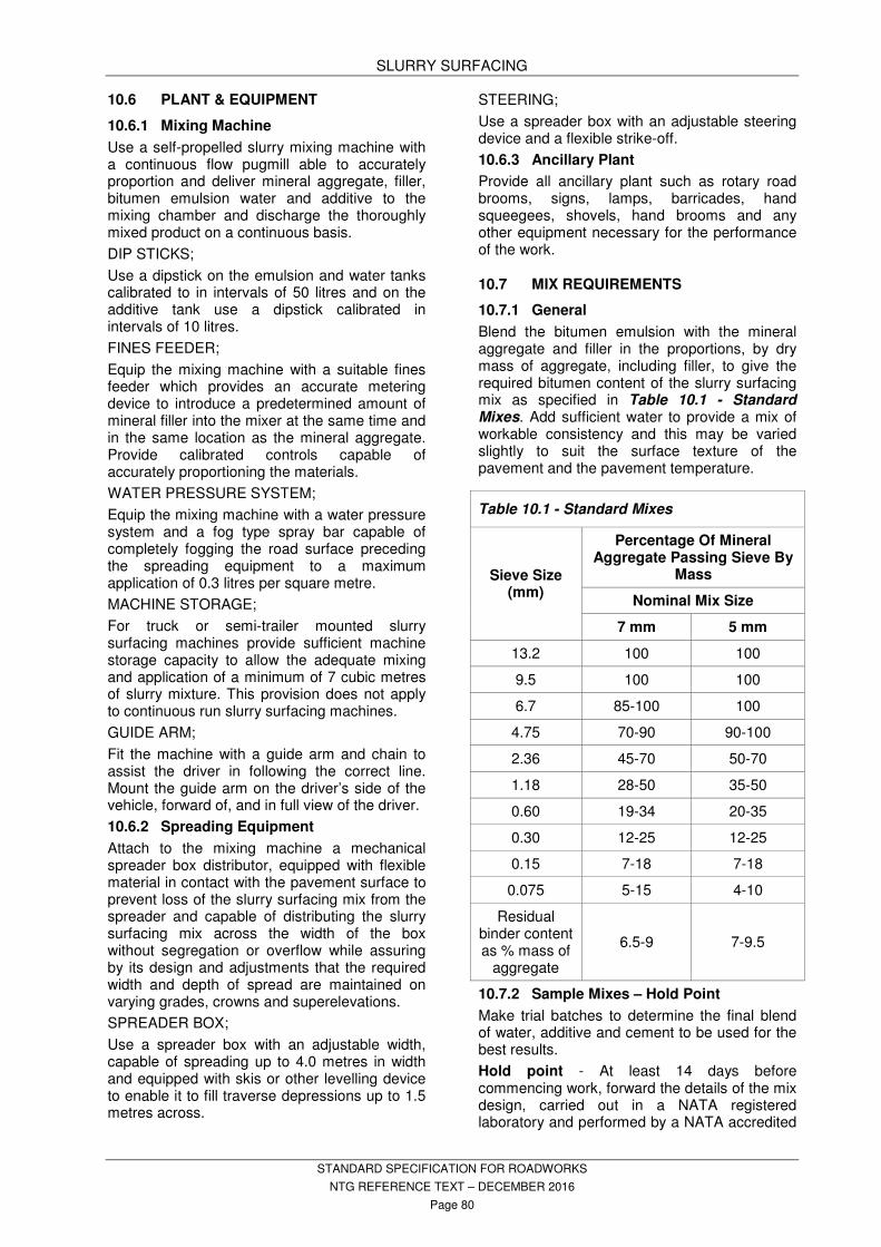
SLURRY SURFACING
STANDARD SPECIFICATION FOR ROADWORKS
NTG REFERENCE TEXT – DECEMBER 2016
Page 80
10.6 PLANT & EQUIPMENT
10.6.1 Mixing Machine
Use a self-propelled slurry mixing machine with a continuous flow pugmill able to accurately proportion and deliver mineral aggregate, filler, bitumen emulsion water and additive to the mixing chamber and discharge the thoroughly mixed product on a continuous basis.
DIP STICKS;
Use a dipstick on the emulsion and water tanks calibrated to in intervals of 50 litres and on the additive tank use a dipstick calibrated in intervals of 10 litres.
FINES FEEDER;
Equip the mixing machine with a suitable fines feeder which provides an accurate metering device to introduce a predetermined amount of mineral filler into the mixer at the same time and in the same location as the mineral aggregate. Provide calibrated controls capable of accurately proportioning the materials.
WATER PRESSURE SYSTEM;
Equip the mixing machine with a water pressure system and a fog type spray bar capable of completely fogging the road surface preceding the spreading equipment to a maximum application of 0.3 litres per square metre.
MACHINE STORAGE;
For truck or semi-trailer mounted slurry surfacing machines provide sufficient machine storage capacity to allow the adequate mixing and application of a minimum of 7 cubic metres of slurry mixture. This provision does not apply to continuous run slurry surfacing machines.
GUIDE ARM;
Fit the machine with a guide arm and chain to assist the driver in following the correct line. Mount the guide arm on the driver’s side of the vehicle, forward of, and in full view of the driver.
10.6.2 Spreading Equipment
Attach to the mixing machine a mechanical spreader box distributor, equipped with flexible material in contact with the pavement surface to prevent loss of the slurry surfacing mix from the spreader and capable of distributing the slurry surfacing mix across the width of the box without segregation or overflow while assuring by its design and adjustments that the required width and depth of spread are maintained on varying grades, crowns and superelevations.
SPREADER BOX;
Use a spreader box with an adjustable width, capable of spreading up to 4.0 metres in width and equipped with skis or other levelling device to enable it to fill traverse depressions up to 1.5 metres across.
STEERING;
Use a spreader box with an adjustable steering device and a flexible strike-off.
10.6.3 Ancillary Plant
Provide all ancillary plant such as rotary road brooms, signs, lamps, barricades, hand squeegees, shovels, hand brooms and any other equipment necessary for the performance of the work.
10.7 MIX REQUIREMENTS
10.7.1 General
Blend the bitumen emulsion with the mineral aggregate and filler in the proportions, by dry mass of aggregate, including filler, to give the required bitumen content of the slurry surfacing mix as specified in Table 10.1 - Standard Mixes. Add sufficient water to provide a mix of workable consistency and this may be varied slightly to suit the surface texture of the pavement and the pavement temperature.
10.7.2 Sample Mixes – Hold Point
Make trial batches to determine the final blend of water, additive and cement to be used for the best results.
Hold point - At least 14 days before commencing work, forward the details of the mix design, carried out in a NATA registered laboratory and performed by a NATA accredited
Table 10.1 - Standard Mixes
Sieve Size (mm)
Percentage Of Mineral Aggregate Passing Sieve By
Mass
Nominal Mix Size
7 mm 5 mm
13.2 100 100
9.5 100 100
6.7 85-100 100
4.75 70-90 90-100
2.36 45-70 50-70
1.18 28-50 35-50
0.60 19-34 20-35
0.30 12-25 12-25
0.15 7-18 7-18
0.075 5-15 4-10
Residual binder content as % mass of
aggregate
6.5-9 7-9.5

SLURRY SURFACING
STANDARD SPECIFICATION FOR ROADWORKS
NTG REFERENCE TEXT – DECEMBER 2016
Page 81
technician, to the Superintendent for endorsement. Once the mix design is endorsed by the Superintendent it becomes the specified job mix.
10.7.3 Departures from the Job Mix – Table
The following table provides the maximum mean departures from the job mix for any day’s work.
If the mix gradings and binder content depart from the job mix by more than any of the maxima shown in the table, halt production until the mix is corrected.
10.8 PREPARATION AND SET OUT
10.8.1 Sweeping Pavement – Hold Point
Immediately prior to any application of slurry surfacing mix, sweep the pavement as necessary to ensure that the surface is free of loose material, stones, dirt, dust and foreign matter by the use of a mechanically operated rotary road broom, unless otherwise authorised by the Superintendent. Carry out additional sweeping necessary to obtain a satisfactory clean surface by hand using stiff brass or similar brooms.
PREVIOUSLY SEALED AREAS;
Prior to the application of slurry surfacing mix adjoining previously sealed areas, sweep the edges of the previously sealed areas to remove loose material for at least 150 mm from the edge.
FOREIGN MATERIAL;
Remove adherent patches of foreign material from the surface of the road by steel scraper or other suitable methods. Do not remove any large deposits of foreign material that cannot be removed by reasonable use of the mechanical broom, steel scrapers or other suitable methods. Report the existence of any such deposits to the
Superintendent prior to the commencement of spreading.
Hold point - Do not commence spreading of the slurry surfacing mix until the prepared pavement has been endorsed by the Superintendent.
SET OUT;
Unless following a satisfactory edge line or centre line place pavement marks on the surface at intervals of not more than 8 metres for the slurry surfacing machine to follow, while mixing and spreading.
10.9 APPLICATION
Deposit the slurry surfacing mix at the optimum consistency into the spreading box and add nothing more to it. Ensure that the mixing time is sufficient to produce a complete and uniform coating of the aggregate and direct the mixture into the moving spreader box at a sufficient rate to maintain an ample supply across the full width of the strike-off squeegee at all times.
SLURRY BUILD UP; If required, squirt minor amounts of water into the corners of the spreader box to overcome temporary buildup of slurry surfacing mixture. This has no detrimental effect on the performance of the slurry.
END OF RUN;
Square off the end of each run at the point where feathering commenced ( ie. that point where there is insufficient material in the spreader box to maintain the full width of spread). Alternatively, the successive run may be lapped, but by no more than 100mm, if it can be demonstrated that no loss of riding surface or fattiness will result.
INACCESSABLE AREAS;
Use suitable hand squeegees to spread the mix in areas inaccessible to the machine.
JOINTS;
Make longitudinal joints coincide with lane or centreline markings. Provide suitable width spreading equipment to produce a minimum number of longitudinal joints throughout the work. Half passes and odd width passes may be used where necessary for shape correction but must not be used as the last pass of any paved area. Do not allow excessive build up or unsightly appearance on longitudinal or traverse joints.
KERBS AND SHOULDERS;
Take care to ensure straight lines along kerbs and shoulders and do not allow run off on those areas.
Table 10.2 - Maximum Mean Departures From The Job Mix
Sieve Size In mm
% By Mass
Aggregate 6.7 7
4.75 7
2.36 5
1.18 5
0.60 4
0.30 4
0.15 3
0.075 2
Bitumen Content + 1.0 - 0.5

SLURRY SURFACING
STANDARD SPECIFICATION FOR ROADWORKS
NTG REFERENCE TEXT – DECEMBER 2016
Page 82
TEMPERATURE;
If the pavement temperature exceeds 40 degrees C., immediately prior to the application of the slurry surfacing mix thoroughly wet the surface of the pavement and all crack faces with water. Ensure that all surfaces are uniformly damp and no free water is present on the surface or in the cracks when the slurry surfacing mix is applied.
DAMAGED WORK;
Replace slurry surfacing damaged by unexpected rain after spreading.
10.10 TESTING
MATERIALS TESTING;
Sampling of the mixed material will be requested randomly by the Superintendent during each days production.
The sample material will be tested by the Principal’s NATA accredited testing laboratory contractor using accredited NATA technicians and test results will be provided to the Contractor.
EXCESS AGGREGATE LOSS;
Should the Superintendent identify excess aggregate loss from the surface after the slurry has fully cured, and the mix proportions are within the specified limits, suspend work until tests are taken and the problems rectified.
- Wet stripping test; ISSA TB 114 (minimum 90% coating) to assess the system’s coating compatibility with the aggregate source.
- Wet track abrasion test; by AGPT/T272, SST 04 (maximum 800g/m2 loss). If the wet track abrasion re-test value exceeds 800g/m2, halt production until the mix design is corrected and endorsed by the Superintendent.
10.11 SURPLUS, WASTE AND DEFECTIVE MATERIALS
Remove from the work prior to its application to the road any bitumen emulsion which has deteriorated or become contaminated in any way. Bear the cost of replacing any such emulsion for use in the works.
SURPLUS MATERIALS;
Remove surplus materials in stockpiles and elsewhere from the job at the completion of the work.
WASTE;
Dispose of waste aggregate, bitumen emulsion, empty containers or other materials remaining after completion of the work in an acceptable manner and leave the work site in a neat and tidy condition.
10.12 MAINTENANCE
Maintain the completed work in a satisfactory condition for a period of one month after completion of the whole of the work. Maintenance is limited to work which results from failures attributable to the operations of the Contractor.
10.13 RECORDS – WITNESS POINT
Record the particulars of the slurry surfacing work, as required by the Superintendent, on the Department’s standard “Daily Record Sheet – Spray Surfacing”. Record the details of aggregate, added filler, emulsion and additive used together with the length and width of run immediately each run is completed.
Witness point - Forward the original copy of the slurry surfacing Daily Record Sheet to the Superintendent daily.
10.14 OTHER REQUIREMENTS
Refer to PROJECT SPECIFIC REQUIREMENTS in the RFT.

MISCELLANEOUS CONCRETE
STANDARD SPECIFICATION FOR ROADWORKS
NTG REFERENCE TEXT – DECEMBER 2016
Page 83
11 MISCELLANEOUS CONCRETE
11.1 STANDARDS
Conform to the following Standards and Publication unless specified otherwise:
AS 1012 Methods of testing concrete AS 1141 Methods for sampling and
testing aggregates AS 1289 Methods of testing soils for
engineering purposes AS 1379 Specification and supply of
concrete AS 1478.1 Chemical admixtures for
concrete AS 2349 Method of sampling portland
and blended cements AS 2350(set) Methods of testing portland and
blended cements AS 2758.1 Aggregates and rock for
engineering purposes - Concrete aggregates
AS 2876 Concrete kerbs and channels (gutters) - Manually or machine placed
AS 3600 Concrete structures AS 3610 Formwork for concrete AS 3972 General purpose and blended
cements AS/NZS 4671 Steel reinforcing materials NTMTM NT Materials Testing Manual NTTM NT Test Methods
11.2 GENERAL
This section specifies miscellaneous minor concrete works and does not apply to buildings or bridges. It is for incidental Concrete Works. It should not be used for concrete pavements. Concrete pavements require a specific "one off" specification developed as required.
CROSS REFERENCE
Refer to CONFORMANCE TESTING for sampling frequencies for fresh concrete.
11.3 MATERIALS
Provide manufacturer's test certificates for quality of cement, aggregate and reinforcement.
11.3.1 Cement
Type GP or GB to AS 3972.
Store cement in watertight containers or shelters until used.
Do not mix or store special cement with normal Portland cement.
11.3.2 Fine Aggregate
Clean, hard, tough, durable, uncoated grains, homogeneous in quality, free from clay, dirt and organic material.
11.3.3 Coarse Aggregate
Clean, hard, durable, crushed stone or gravel, free from clay, dirt and organic material.
11.3.4 Water
Clean and free from oil, alkali, organic or other deleterious substances.
11.3.5 Chemical Admixtures - Hold Point
Hold Point - Do not use admixtures without obtaining prior written approval from the Superintendent.
Admixtures and their use must conform to AS 1478.1.
Where two or more chemical admixtures are proposed for incorporation into a concrete mix, their compatibility must be certified by the manufacturers.
Store admixtures in accordance with the manufacturer’s recommendations.
11.3.6 Reinforcement – Hold Point
Standard: To AS/NZS 4671
Supply, cut, bend and fix steel reinforcement as specified.
Secure reinforcement and bar supports to prevent displacement during construction and concrete placement.
Hold point - Do not place concrete until the reinforcement has been inspected by the Superintendent.
11.3.7 Recycled Crushed Glass (RCG)
Clean, hard, durable RCG free from clay, dirt and organic material. Source the material from glass food and beverage containers, drinking glasses, and window (or flat) glass and plain ceramic. Do not use glass from hazardous waste containers, reinforced and laminated glass, light bulbs, fluorescent tubes and cathode ray tubes. The source glass must be free of debris and contaminants such as paper and cardboard, plastic, fabrics, residues from original contents and toxins.
Use RCG conforming to Specifications for Recycled Crushed Glass as an Engineering Material Section 9 available at
https://infrastructure.nt.gov.au/specification-services/technical-specifications

MISCELLANEOUS CONCRETE
STANDARD SPECIFICATION FOR ROADWORKS
NTG REFERENCE TEXT – DECEMBER 2016
Page 84
11.4 CONCRETE
11.4.1 Ready-mix Concrete
Refer to PROJECT SPECIFIC REQUIREMENTS in the RFT for special requirements.
Supply concrete with the following properties unless specified otherwise:
Compressive strength N25
Aggregate size, generally 20 mm
Aggregate size, machine extruded kerbs and gutters
10 mm
Slump 80 mm, + or - 15 mm
Conduct slump testing on site for each and every truck.
11.4.2 Job-mixed Concrete
Use Project Assessment in accordance with AS 3600.
The Contractor will be responsible for sampling and testing.
Provide Project Assessment reports that encompass the period of concrete works. Not required where insignificant structures and volumes and/or remote locations are involved.
Refer to PROJECT SPECIFIC REQUIREMENTS in the RFT for special requirements.
Provide concrete with properties as specified for ready-mix concrete.
Determine the quantities of materials to be used by mass or by equivalent dry loose volume.
Provide and maintain gauges for measurement of the materials.
11.4.3 Addition of Admixtures
Refer to Clause 11.3.5 Chemical Admixtures - Hold Point
Chemical admixtures may only be added subsequent to slump test compliance confirmation. A further slump test post admixture addition may also be required.
Where Superintendent approval has been granted for the addition of superplasticisers at the plant prior to dispatch of concrete, a slump test of each batch must be performed and recorded by a NATA accredited testing laboratory prior to the addition of the superplasticiser. The slump test report shall record the time of the addition of the superplasticiser, amount of superplasticiser added and product identification.
Do not add chemical admixtures unless the exact amount required is measured using a
regularly maintained and calibrated device of the required accuracy.
Make allowance for the reversion time of superplasticisers. Delay the addition of superplasticisers as long as practicable before the concrete is discharged from the mixer.
Agitate concrete for at least 5 minutes following the addition of superplasticiser before dispensing.
11.5 FOUNDATIONS
Provide a foundation compacted to 90% relative density within 150 mm of the base of concrete.
11.6 CONSTRUCTION
11.6.1 Kerbs and Gutters
Construct kerbs and gutters as integral units.
11.6.2 Formwork – Witness Point
Design and construct forms so that they are mortar tight and can be removed without damaging the concrete.
Build forms true to line and braced in a substantial and non-yielding manner.
Witness point - Do not place concrete until the formwork has been inspected by the Superintendent.
11.6.3 Placing of Concrete – Witness Point – Hold Point
Witness point - Give the Superintendent sufficient notice so that inspection may be made before and during pouring concrete. Hold point - Provide verification that all constituent materials, formwork, falsework, reinforcement, and environmental conditions comply with all requirements. Do not cast any concrete without that verification. Do not place concrete if the temperature of the concrete exceeds 35°C, or if the ambient air temperature exceeds 40°C . Place and compact concrete within the following time after the addition of the mixing water to the mix:
Place concrete in a continuous operation between construction joints so that the face of the concrete is in a plastic state when succeeding concrete is placed against it.
Table 11.1 - Maximum Time To Place Concrete After Mixing
Concrete Temperature At Time Of Placing
Maximum Time (minutes)
25 °C to 28 °C 75
28 °C to 32 °C 60
32 °C to 35 °C 45

MISCELLANEOUS CONCRETE
STANDARD SPECIFICATION FOR ROADWORKS
NTG REFERENCE TEXT – DECEMBER 2016
Page 85
Do not allow concrete to free-fall from a height greater than 1.5 metres.
Place all concrete in dry weather unless otherwise approved.
For each truck of premixed concrete provide an identification certificate on delivery listing the information required by AS 1379 and any other particular requirements for special class concrete.
11.6.4 Jointing
CONSTRUCTION JOINTS
Roughen and clean face of hardened concrete before placing fresh concrete against it. Remove soft material, foreign matter and laitance. Thoroughly moisten the joint surface.
EXPANSION/CONTRACTION JOINTS
Joints to be 10 mm wide over full length and filled with a bitumen impregnated fibrous filler.
Provide vertical transverse expansion / contraction joints as follows:
Footpaths: 6 m spacing maximum.
At junctions with other concrete structures
Inverts: 15 m spacing maximum.
All other works: As shown on the drawings.
TOOLED JOINTS
Provide tooled joints as follows:
Transverse vertical grooves 20 mm depth minimum.
Joints at right angles to outer edge of concrete works.
Footpaths: 2 m spacing maximum.
Kerbs/Inverts: 3 m spacing maximum.
All other works: As shown on the drawings.
11.6.5 Surface Finishes
Finish surfaces to a smooth and even colour.
Remove free surface water during final screeding of unformed surfaces.
Round off exposed edges and corners.
Protect exposed surfaces from rain until final set has occurred.
Smooth tumbled RCG used as an exposed aggregate surface finish.
Conform to Table 11.3 – Concrete Finishes.
11.6.6 Curing
Protect and cure all exposed surfaces immediately after the concrete has taken its initial set.
Maintain all surfaces, including those within loosened formwork, in a moist condition by:
- flooding;
- continuous spraying with water; or
- other methods approved by the Superintendent.
Prevent staining during the curing process of all concrete surfaces that will be visible in the completed works. Continuously maintain the protection and curing of each element for the minimum time specified by AS 3600 to provide the concrete with durability corresponding to the specified exposure classification. Do not use curing compounds in lieu of moist curing unless approved.
11.6.7 Backfilling
Backfill areas around the concrete with Select Fill or as otherwise specified. Refer to EARTHWORKS section. Compact the backfilling in layers not exceeding 150 mm compacted thickness. Reinstate damaged grassed areas with topsoil and grass seed.
11.7 RAIN DAMAGE Remove and replace rain damaged concrete.
11.8 EXISTING SERVICES – HOLD POINT
Hold point - Obtain the Superintendent's approval before altering the line or level of existing services. Place an expansion joint between concrete works and service.
11.9 CONFORMANCE Refer to DRAINAGE WORKS for culvert structures and pits. Conform to the following: Table 11.2 - Tolerances - Misc. Concrete Aspect measured Tolerance
Finished level + or -15 mm from the specified level
Invert level + or -5 mm from the specified level
Straight edge deviation of surface
3 mm max. in 3 m - 6 mm max. in 15 m
Alignment + or -10 mm from the specified alignment
Chainage at vehicle crossing
+ or -150 mm
Width of vehicle crossing
+ or -25 mm
11.10 DEFECTIVE CONCRETE AND MATERIALS
Concrete which is not placed, cured or finished as specified, does not have the specified strength or other specified properties, is not sound, dense, durable or crack-free will be considered defective.

MISCELLANEOUS CONCRETE
STANDARD SPECIFICATION FOR ROADWORKS
NTG REFERENCE TEXT – DECEMBER 2016
Page 86
Bear all cost and delays resulting from the rejection of concrete and subsequent rectification.
Remove the concrete to a point agreed with the Superintendent at which a visually and structurally acceptable construction joint can be made, and the defective element rebuilt.
Repair defective surface finishes if approved by the Superintendent. Approval will not be given if the defective area is too extensive or the techniques proposed are not adequate to ensure a visually acceptable and durable repair.
11.11 OTHER REQUIREMENTS
Refer to PROJECT SPECIFIC REQUIREMENTS in the RFT.
Table 11.3 – Concrete Finishes
Type Description Application
S1 Left rough to give key but not honeycombed or porous
Surfaces to be rendered.
S2 Wood float As specified.
S3 Steel trowel without polish Internal surfaces subject to foot traffic. Kerb and gutter.
S4 Wood float and broomed finish - broom finish - broom across direction of traffic
Surfaces subject to vehicular traffic.
S6 Steel float followed by moist hair broom Surfaces subject to foot traffic.
F1 Remove mortar fins, etc., repair minor blow holes by bagging where approved or rub down with Carborundum stone
Formed surfaces exposed to view.
F2 Off forms -
F3 Exposed RCG
Application of RCG to be hand spread once application of the exposed mix has been bull floated.
RCG to be measured 1000 grams per square meter, or as otherwise specified by the Superintendent.
Colour and size of RCG to be specified by Superintendent.

DRAINAGE WORKS
STANDARD SPECIFICATION FOR ROADWORKS
NTG REFERENCE TEXT – DECEMBER 2016
Page 87
12 DRAINAGE WORKS
12.1 STANDARDS
Conform to the following Standards and Publications unless specified otherwise:
AS 1012(set) Methods of testing concrete. AS 1141(set) Methods for sampling and
testing aggregates. AS 1289(set) Methods of testing soil for
engineering purposes. AS 1379 Specification and supply of
concrete. AS 1478.1 Chemical admixtures for
concrete. AS 1597(set) Precast reinforced concrete box
culverts. AS/NZS 2041 (set) Buried corrugated metal
structures. AS 2349 Method of sampling portland
and blended cements. AS 2350 Methods of testing portland and
blended cements. AS 2439 Perforated plastics drainage
and effluent pipe and fittings. AS 2758.1 Aggregates and rock for
engineering purposes - Concrete aggregates.
AS 3600 Concrete structures. AS 3610 Formwork for concrete. AS 3706(set) Geotextiles - Methods of test. AS/NZS 3725 Design for installation of buried
concrete pipes. AS 3972 Portland and blended cements. AS/NZS 4058 Precast concrete pipes
(pressure and non-pressure). AS/NZS 4671 Steel reinforcing materials AS 5100.5 Bridge Design - Concrete NTMTM NT Materials Testing Manual. NTTM NT Test Methods AUSTROADS AGBT Set Guide to Bridge Technology. ARRB Specifications for Recycled Crushed Glass as an Engineering Material WorkSafe Australia Excavation Work Code of Practice
12.2 DEFINITIONS
CULVERT:
An underground pipe, box or arch constructed in an embankment or trench.
CULVERT SKEW ANGLE:
The angle between a line drawn perpendicular or radial to the road centre line and the centre line of the culvert.
CULVERT CHAINAGE:
The chainage measured along the road centre line at its intersection with the culvert centre line.
LARGE BOX CULVERTS:
Precast box culverts and link slabs having spans greater than 1200 mm, heights greater than 1200 mm or fill heights exceeding 1600 mm.
RECYCLED CRUSHED GLASS (RCG):
RCG conforming to Specifications for Recycled Crushed Glass as an Engineering Material Section 9. A copy is available at https://infrastructure.nt.gov.au/specification-services/technical-specifications .
TOM(S)
Devices used to hold pipe culverts in place during backfilling of trenches.
Also;
Horizontal device(s), such as timbers, metal struts, hydraulic spreaders, etc, spanning across an excavation for holding soldiers (vertical timbers) or walings (horizontal timbers) in place against the sides of trenches before and during trench backfilling.
UNSUITABLE MATERIAL
Any material that does not conform to the properties specified for the replacement materials to be used. If properties of the replacement materials to be used are not specified, then UNSUITABLE MATERIALS are materials which do not conform to the properties specified for standard fill.
12.3 GENERAL
This section applies to the construction of precast concrete pipe culverts not exceeding 1950 mm nominal diameter, precast concrete box culverts and other drainage items.
12.4 CLEARING
Clear the site as specified in the CLEARING, GRUBBING AND REHABILITATION Section.
12.5 MATERIALS
Conformance testing will be the responsibility of the Contractor.
Ensure that all pipes and box culverts are indelibly marked with a Standards Australia conformance stamp.
Pipes and box culverts not stamped shall be removed from site at the Contractor's expense.
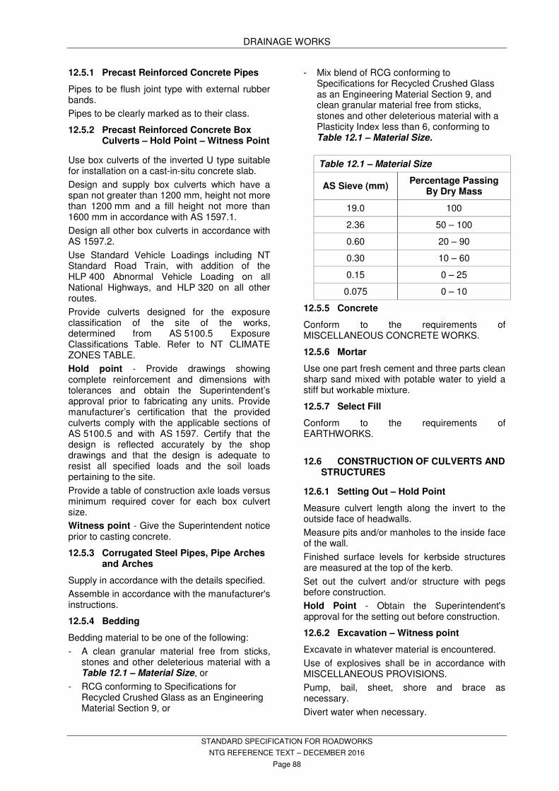
DRAINAGE WORKS
STANDARD SPECIFICATION FOR ROADWORKS
NTG REFERENCE TEXT – DECEMBER 2016
Page 88
12.5.1 Precast Reinforced Concrete Pipes
Pipes to be flush joint type with external rubber bands.
Pipes to be clearly marked as to their class.
12.5.2 Precast Reinforced Concrete Box Culverts – Hold Point – Witness Point
Use box culverts of the inverted U type suitable for installation on a cast-in-situ concrete slab.
Design and supply box culverts which have a span not greater than 1200 mm, height not more than 1200 mm and a fill height not more than 1600 mm in accordance with AS 1597.1.
Design all other box culverts in accordance with AS 1597.2.
Use Standard Vehicle Loadings including NT Standard Road Train, with addition of the HLP 400 Abnormal Vehicle Loading on all National Highways, and HLP 320 on all other routes.
Provide culverts designed for the exposure classification of the site of the works, determined from AS 5100.5 Exposure Classifications Table. Refer to NT CLIMATE ZONES TABLE.
Hold point - Provide drawings showing complete reinforcement and dimensions with tolerances and obtain the Superintendent’s approval prior to fabricating any units. Provide manufacturer’s certification that the provided culverts comply with the applicable sections of AS 5100.5 and with AS 1597. Certify that the design is reflected accurately by the shop drawings and that the design is adequate to resist all specified loads and the soil loads pertaining to the site.
Provide a table of construction axle loads versus minimum required cover for each box culvert size.
Witness point - Give the Superintendent notice prior to casting concrete.
12.5.3 Corrugated Steel Pipes, Pipe Arches and Arches
Supply in accordance with the details specified.
Assemble in accordance with the manufacturer's instructions.
12.5.4 Bedding
Bedding material to be one of the following:
- A clean granular material free from sticks, stones and other deleterious material with a Table 12.1 – Material Size, or
- RCG conforming to Specifications for Recycled Crushed Glass as an Engineering Material Section 9, or
- Mix blend of RCG conforming to Specifications for Recycled Crushed Glass as an Engineering Material Section 9, and clean granular material free from sticks, stones and other deleterious material with a Plasticity Index less than 6, conforming to Table 12.1 – Material Size.
12.5.5 Concrete
Conform to the requirements of MISCELLANEOUS CONCRETE WORKS.
12.5.6 Mortar
Use one part fresh cement and three parts clean sharp sand mixed with potable water to yield a stiff but workable mixture.
12.5.7 Select Fill
Conform to the requirements of EARTHWORKS.
12.6 CONSTRUCTION OF CULVERTS AND STRUCTURES
12.6.1 Setting Out – Hold Point
Measure culvert length along the invert to the outside face of headwalls.
Measure pits and/or manholes to the inside face of the wall.
Finished surface levels for kerbside structures are measured at the top of the kerb.
Set out the culvert and/or structure with pegs before construction.
Hold Point - Obtain the Superintendent's approval for the setting out before construction.
12.6.2 Excavation – Witness point
Excavate in whatever material is encountered.
Use of explosives shall be in accordance with MISCELLANEOUS PROVISIONS.
Pump, bail, sheet, shore and brace as necessary.
Divert water when necessary.
Table 12.1 – Material Size
AS Sieve (mm) Percentage Passing
By Dry Mass
19.0 100
2.36 50 – 100
0.60 20 – 90
0.30 10 – 60
0.15 0 – 25
0.075 0 – 10
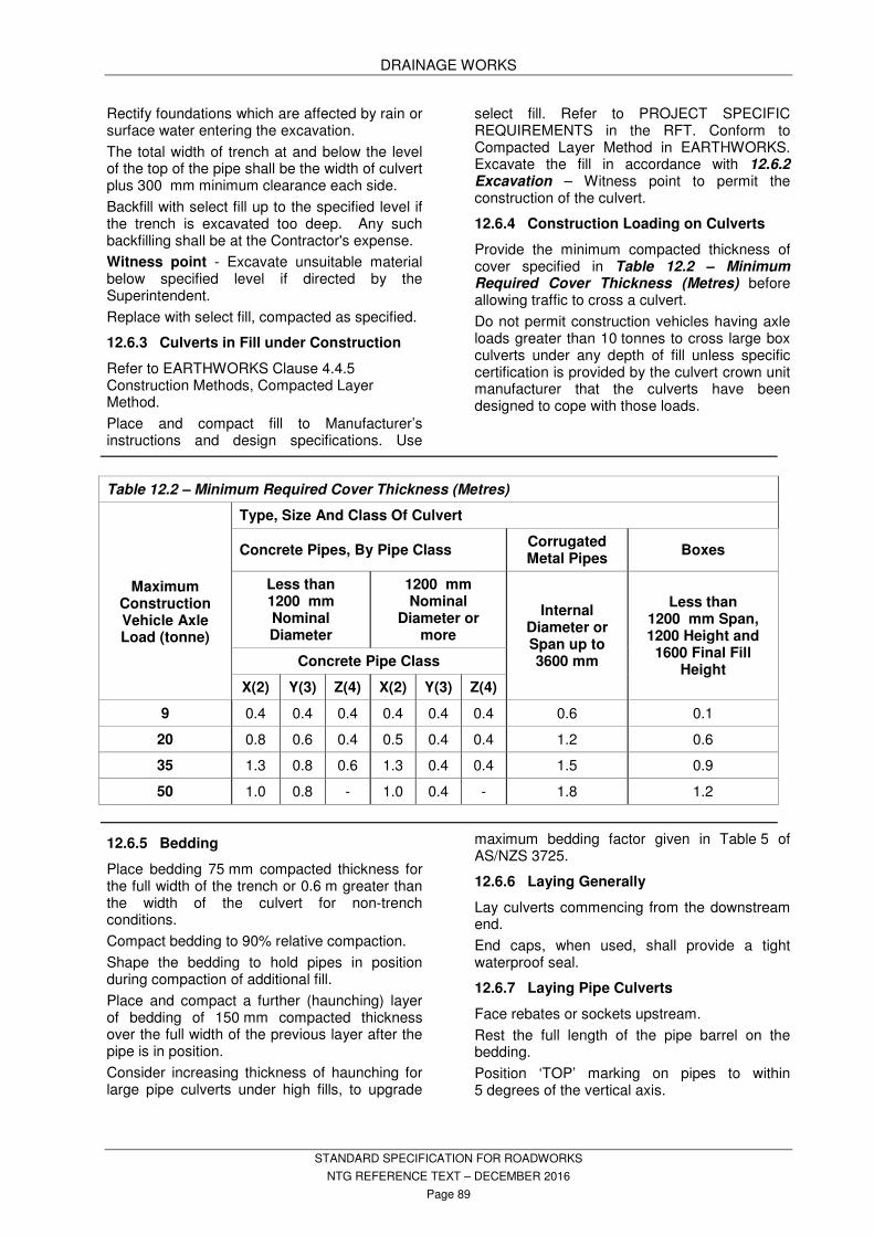
DRAINAGE WORKS
STANDARD SPECIFICATION FOR ROADWORKS
NTG REFERENCE TEXT – DECEMBER 2016
Page 89
Rectify foundations which are affected by rain or surface water entering the excavation.
The total width of trench at and below the level of the top of the pipe shall be the width of culvert plus 300 mm minimum clearance each side.
Backfill with select fill up to the specified level if the trench is excavated too deep. Any such backfilling shall be at the Contractor's expense.
Witness point - Excavate unsuitable material below specified level if directed by the Superintendent.
Replace with select fill, compacted as specified.
12.6.3 Culverts in Fill under Construction
Refer to EARTHWORKS Clause 4.4.5 Construction Methods, Compacted Layer Method.
Place and compact fill to Manufacturer’s instructions and design specifications. Use
select fill. Refer to PROJECT SPECIFIC REQUIREMENTS in the RFT. Conform to Compacted Layer Method in EARTHWORKS. Excavate the fill in accordance with 12.6.2 Excavation – Witness point to permit the construction of the culvert.
12.6.4 Construction Loading on Culverts
Provide the minimum compacted thickness of cover specified in Table 12.2 – Minimum Required Cover Thickness (Metres) before allowing traffic to cross a culvert.
Do not permit construction vehicles having axle loads greater than 10 tonnes to cross large box culverts under any depth of fill unless specific certification is provided by the culvert crown unit manufacturer that the culverts have been designed to cope with those loads.
12.6.5 Bedding
Place bedding 75 mm compacted thickness for the full width of the trench or 0.6 m greater than the width of the culvert for non-trench conditions.
Compact bedding to 90% relative compaction.
Shape the bedding to hold pipes in position during compaction of additional fill.
Place and compact a further (haunching) layer of bedding of 150 mm compacted thickness over the full width of the previous layer after the pipe is in position.
Consider increasing thickness of haunching for large pipe culverts under high fills, to upgrade
maximum bedding factor given in Table 5 of AS/NZS 3725.
12.6.6 Laying Generally
Lay culverts commencing from the downstream end.
End caps, when used, shall provide a tight waterproof seal.
12.6.7 Laying Pipe Culverts
Face rebates or sockets upstream.
Rest the full length of the pipe barrel on the bedding.
Position ‘TOP’ marking on pipes to within 5 degrees of the vertical axis.
Table 12.2 – Minimum Required Cover Thickness (Metres)
Maximum Construction Vehicle Axle Load (tonne)
Type, Size And Class Of Culvert
Concrete Pipes, By Pipe Class Corrugated Metal Pipes
Boxes
Less than 1200 mm Nominal Diameter
1200 mm Nominal
Diameter or more
Internal Diameter or Span up to 3600 mm
Less than 1200 mm Span, 1200 Height and 1600 Final Fill
Height Concrete Pipe Class
X(2) Y(3) Z(4) X(2) Y(3) Z(4)
9 0.4 0.4 0.4 0.4 0.4 0.4 0.6 0.1
20 0.8 0.6 0.4 0.5 0.4 0.4 1.2 0.6
35 1.3 0.8 0.6 1.3 0.4 0.4 1.5 0.9
50 1.0 0.8 - 1.0 0.4 - 1.8 1.2

DRAINAGE WORKS
STANDARD SPECIFICATION FOR ROADWORKS
NTG REFERENCE TEXT – DECEMBER 2016
Page 90
Fill all joints with stiff mortar firmly rammed into openings. Remove excess mortar from barrel of culvert. Apply external rubber bands.
Brace pipes of 1200 mm diameter and greater with toms until the completion of the embankment and pavement. The toms shall bear against a sill along the invert and a cap against the crown of the pipe. Provide toms opposite every pipe joint.
Cast collars and blocks in one operation. Restrain the culvert prior to constructing the collars or blocks by partially backfilling with bedding around the barrel of the culvert to one-half of the pipe diameter.
12.6.8 Laying Box Culverts
Lay precast box culverts on a cast-in-situ reinforced concrete base slab.
Ensure concrete base slab exceeds external width of box culverts as shown on the typical details.
Butt box culverts firmly together.
Cut away lifting hooks and seal over the affected area with an approved epoxy resin.
Fill all joints with a stiff mortar firmly rammed into the openings. Remove excess mortar from the barrel of the culvert and apply external joint seals, Densopol HT60 or equivalent, 150 mm wide.
12.6.9 Connection to Existing Systems – Witness Point
Repair all cut openings and make watertight.
Demolish existing headwalls to make way for the extension of the culvert.
Clean out new work and existing work affected by the new work.
Witness Point – Advise superintendent within two days when clean out is completed
12.6.10 Backfill – Witness Point – Hold Point
Witness point - Notify the Superintendent before backfilling where holes or fissures occur in rock trenches.
Hold point - Do not place backfill against any in-situ concrete structure until the concrete has attained 80% characteristic strength and approval has been given.
Place backfill in layers not exceeding 150 mm compacted thickness.
Ensure the maximum difference in height of backfill on each side of a culvert is 300 mm.
Backfill around the culvert for the full width of the trench, and for a minimum 300 mm above the top of the culvert, or to subgrade surface if less, with select fill.
Backfill the remainder of the trench with standard fill.
Stabilise all backfill with 2% cement by mass and compact to 95% relative compaction.
Produce a uniform mix. Complete compaction within one hour of adding mixing water.
Use compaction equipment which will not damage the culvert and in-situ structures.
Carry out conformance testing using the Department’s Panel Period Contractors for Testing.
Stabilise top 150 mm of backfill, for a distance of 1 m adjacent to culvert headwalls and wing walls, so as to be erosion - resistant.
Remove surplus material from the site.
Reinstate to subgrade level trenches cut through pavements and other construction by backfilling the trench with stabilised select fill compacted to 95% relative compaction.
Construct base/sub-base layers of the pavement in accordance with PAVEMENTS AND SHOULDERS.
Reinstate surface.
Reinstate trenches cut outside of pavements and other construction by backfilling with standard fill compacted to 90% relative compaction.
12.7 INLET AND OUTLET STRUCTURES AND MAINTENANCE HOLES
Construct in accordance with the specifications.
Compact foundations to 95% relative compaction to a depth of 150 mm minimum.
Replace unsuitable material as specified in 12.6.2 Excavation
12.8 INLET AND OUTLET CHANNELS – WITNESS POINT
Excavate the inlet and outlet of all culverts to facilitate the flow of water.
Conform to the following:
Bed width: Minimum 150 mm greater than overall width of culvert.
Side batters: 45 degrees maximum to horizontal.
Bed grade: 0.5% in the direction of flow for a minimum distance of 50 metres.
Clean out new work and existing work affected by the new work.
Witness point – Advise superintendent within two days when clean out is completed.

DRAINAGE WORKS
STANDARD SPECIFICATION FOR ROADWORKS
NTG REFERENCE TEXT – DECEMBER 2016
Page 91
12.9 OPEN UNLINED DRAINS
Excavate and dispose of all excess material as specified in EARTHWORKS.
Trim drains to form neat levees.
Compact levees to 95% relative compaction.
Allow natural surface runoff.
12.10 REMOVAL OF EXISTING CULVERTS AND DRAINAGE STRUCTURES
Demolish and remove from the site, as specified, existing culverts and drainage structures.
12.11 SUBSOIL DRAINS 12.11.1 Excavation
Excavate below the top of required depth of cover to drainage devices (pipe or other) to a minimum depth equal to the outside diameter of the pipe or height of other device, plus 75 mm.
Line the trench with geotextile fabric. Refer to PROTECTION WORKS.
Place a bedding layer of 50 mm of filter material in the trench and compact with a vibrating plate or similar.
12.11.2 Filter Material
Shall be a hard durable stone having a Los Angeles Abrasion Loss not greater than 35%.
Conform to the grading specified by the manufacturer of the subsoil pipe. If manufacturer's grading not supplied, conform to Table 12.3 – Filter Material Grading.
12.11.3 Geotextile Fabric
Conform to the requirements of 13.3 Geotextile Fabrics in PROTECTION WORKS.
12.11.4 Subsoil Drain Pipe
Use 100 mm diameter Class 400.
Use compatible couplings and fittings.
Connect solid wall pipe to the subsoil drain pipe for the disposal of collected water.
12.11.5 Laying and Backfilling – Hold Point
Fit the upper end of pipelines with inspection openings and caps supported in a concrete collar.
Hold point - Obtain Superintendent's approval of the pipe installation before backfilling.
Place filter material around the barrel of the pipe and to a height of 200 mm above the pipe.
Compact with a vibrating plate compactor or similar.
Place and compact remaining layers of the filter in layers not exceeding 300 mm.
Prevent contamination of the filter.
Place and compact basecourse gravel, as specified in PAVEMENTS AND SHOULDERS in the top 300 mm of trench.
Place the material in two equal layers compacted to 95% relative compaction.
Where trench excavated through pavement compact upper layer of base course gravel to 100% relative compaction and reinstate surface.
Backfill above solid wall pipes as specified in 12.6.10 Backfill – Witness Point – Hold Point
12.11.6 End Walls – Witness Point
Construct end walls at the outlet of subsoil drains as specified.
Secure 19 mm galvanised wire mesh over the opening.
Mark end walls with guide posts.
Clean out new work and existing work affected by the new work.
Witness Point – Advise Superintendent within two days when clean out is completed.
12.12 CONFORMANCE
Conform to Table 12.4 - Drainage Works Tolerances.
Table 12.4 - Drainage Works Tolerances
Property/dimension Tolerance
Invert level and grade line
No ponding of water.
Open unlined drains + or - 50 mm.
Culverts or lined drains
+ or - 20 mm
Plan position + or - 200 mm.
Culverts parallel to kerbs
+ or - 50 mm.
Concrete structure dimension
+ or - 5 mm.
Concrete thickness: Not less than specified.
Subsoil drain slope 25 mm maximum sag in 8 m.
12.13 OTHER REQUIREMENTS
Refer to PROJECT SPECIFIC REQUIREMENTS in the RFT.
Table 12.3 – Filter Material Grading
AS Sieve (mm) Percentage Passing
37.50 100
19.00 90 – 100
9.50 65 – 85
4.75 45 – 65
0.60 0 – 5
PROTECTION WORKS
STANDARD SPECIFICATION FOR ROADWORKS
NTG REFERENCE TEXT – DECEMBER 2016
Page 92
13 PROTECTION WORKS
13.1 STANDARDS
Conform to the following Standards and Publication unless specified otherwise:
AS 1012 Methods of testing concrete. AS 1141(set) Methods of sampling and
testing aggregates. AS 1141.25.1 Degradation factor – Source
rock (Washington Degradation Test).
AS 1141.26 Secondary minerals content in basic igneous rocks
AS 1141.29 Accelerated soundness index by reflux. Basic igneous rocks
AS 1289(set) Methods of testing soils for engineering purposes.
AS 1725(set) Chain link fabric fencing. AS 2001.2.3.2 Methods of test for textiles –
Method 2.3.2: Physical tests – Determination of maximum force using the grab method.
AS 2423 Coated steel wire fencing products for terrestrial, aquatic and general use.
AS 2758.1 Aggregates and rock for engineering purposes - Concrete aggregates.
AS 3706(set) Geotextiles - Methods of test. AS 3972 General purpose and blended
cements. AS 4133(set) Methods of testing rocks for
engineering purposes. AS/NZS 4671 Steel reinforcing materials AS/NZS 4680 Hot dip galvanized (zinc)
coatings on fabricated ferrous articles.
NTMTM NT Materials Testing Manual. NTTM NT Test Methods
13.2 FOUNDATIONS
Excavate, fill and trim the site to the required shape prior to commencing the protection works.
Compact the top 150 mm of earthworks, on which protection works are to be laid to 90% maximum dry density ratio (modified).
13.3 GEOTEXTILE FABRICS 13.3.1 General
Supply and lay non-woven polypropylene or polyester geotextile fabric, consisting of long chain synthetic polymers composed of at least 95% by mass of polyolefins or polyesters. The geotextile filaments must be rot-proof, chemically stable and must have low water absorbency. Filaments must resist delamination and maintain their dimensional stability in the geotextile.
Non-woven geotextiles must have filaments bonded by needle punching, heat or chemical bonding processes.
Woven geotextiles must have filaments interlaced in two sets, mutually at right angles. One set must be parallel to the longitudinal direction of the geotextile.
Geotextiles must be free of any flaws which may have an adverse effect on the physical and mechanical properties of the geotextile.
Geotextiles must be stabilised against ultra-violet radiation such that, when tested in accordance with AS 3706.11, must have a retained strength of at least 50% after 500 hours of exposure.
13.3.2 Storage, Packaging and Handling
Geotextiles must be stored under protective cover or wrapped with a waterproof, opaque UV protective sheeting to avoid damage prior to installation.
Geotextiles must not be stored directly on the ground or in any manner in which they may be affected adversely by heat, water or soil. The method of storage must be in accordance with recommendations by the manufacturer.
The protected geotextile rolls must be clearly labelled showing manufacturer, type of geotextile, and batch identification number.
Handle rolls with forklifts or similar, using dedicated slings, free of sharp hooks or tongs. Rolls that are dropped, dragged or pushed around on the ground will be rejected.
13.3.3 Delivery and Product Certification
Geotextile must be delivered to site at least 5 days prior to commencement of installation.
Provide a Certificate of Compliance that the geotextile complies with all the requirements as specified, together with test results reported on NATA endorsed test documents. The certificate must not be more than 12 months old.
The Certificate of Compliance to include: quality control documentation for the relevant batch/lots, physical properties sheet, and manufacturer’s letter of certification stating compliance.
13.3.4 Construction
Prepare smooth surfaces for placement of the geotextile, free of sharp objects, large rocks and protruding vegetation.
Place geotextiles just ahead of the advancing face of construction work, with a maximum of 48 hours of placement prior to covering.
Repair punctures and tears.
Where used in trenches or other drainage configurations, place the geotextile to the shape of the prepared surface, folding and overlapping

PROTECTION WORKS
STANDARD SPECIFICATION FOR ROADWORKS
NTG REFERENCE TEXT – DECEMBER 2016
Page 93
where required. Fully envelope drainage materials in trenches.
Unless specified elsewhere in the contract, the overlap must be minimum 300 mm. Overlap to be minimum 500 mm where large ground deformations are expected. Sewing may be permitted provided the seam strength exceeds the parent material grab strength.
Direct travel of machinery over geotextile not permitted.
Where required, conform to the following initial layer of material thicknesses:
Table 13.1 - Minimum Initial Layer Thickness (mm)
Nominal Maximum Particle Size D85 of
Initial Fill Layer (mm)
Minimum Initial Layer Thickness (mm)
< 150 300
150 - 300 400
300 - 500 500
Rock armour placed directly on geotextiles must be placed with a drop height of less than 1.5m, and placed in a such a manner so as not to damage, puncture or tear the geotextile.
Obtain Superintendent approval for use of vibratory compaction methods on the initial layer.
13.3.5 Geotextile Grades
Unless specified elsewhere in the contract, use: non-woven, Strength Grade B.
All strength grades, where specified, based on a Characteristic Values (Q), to conform to the table:
Table 13.2 – Geotextile Strength Grade Properties
Geo textile
Strength Grade
Elong-ation
(1)
Grade Strength
(2) (N)
Tear (2)
(N)
G Rating
(2)
A >30%
<30%
500
800
180
300
900
1350
B >30%
<30%
700
1100
250
400
1350
2000
C >30%
<30%
900
1400
350
500
2000
3000
D >30%
<30%
1200
1900
450
700
3000
4500
E >30% 1600 650 4500
Notes:
(1) % Elongation corresponding to max CBR burst strength as per AS 3706.4. Generally <30% for wovens, >30% for non-wovens.
(2) Property value is 80th percentile
characteristic value (mean strength – 0.83 x standard deviation), as per relevant AS test.
Filtration properties relevant to each grade to be certified as part of 13.3.3 Delivery and Product Certification requirements.
13.3.6 Conformance Testing
Where project requirement is less than 15,000 m
2, sampling and testing is not required.
Provide samples to independent, NATA accredited testing laboratory when project exceeds 15,000 m
2, to the following test
frequencies:
Table 13.3 – Test Frequencies
Description Units Test
Method Test
Frequency
Tensile Strength
kN/m AS 3706.2 1 per
15,000 m2
Tear Strength
N AS 3706.3 1 per
15,000 m2
CBR Burst Strength
N AS 3706.4 1 per
15,000 m2
Grade Tensile Strength
N AS 2001.2
.3.2 1 per
15,000 m2
Flow Rate l/m2/s AS 3706.9 1 per
90,000 m2
Samples to be 15 m2 in size, cut across full
width of the roll, not within 2 m of the end of a roll.
13.4 ROCK PROPERTIES
The rock properties specified in this clause apply to the rock, stone, aggregate and boulders specified in the following clauses in this section;
− Stone Pitching
− Dumped Rock
− Quarter Tonne Dumped Rock
− Rubble
− Gabion Rock
− Reno Mattresses
REQUIREMENTS; Clean, dry, durable crushed stone of uniform quality, free from declared weeds and their seeds, vegetable matter and other deleterious materials.
Particles must have at least 2 crushed faces and comply with the following standards;
AS 1141.25.1 Degradation factor – Source rock (Washington Degradation
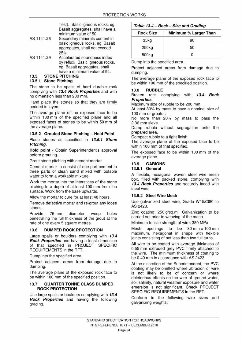
PROTECTION WORKS
STANDARD SPECIFICATION FOR ROADWORKS
NTG REFERENCE TEXT – DECEMBER 2016
Page 94
Test). Basic igneous rocks, eg. Basalt aggregates, shall have a minimum value of 50.
AS 1141.26 Secondary minerals content in basic igneous rocks, eg. Basalt aggregates, shall not exceed
25%. AS 1141.29 Accelerated soundness index
by reflux. Basic igneous rocks, eg. Basalt aggregates, shall have a minimum value of 94.
13.5 STONE PITCHING 13.5.1 Stone Pitching
The stone to be spalls of hard durable rock complying with 13.4 Rock Properties and with no dimension less than 200 mm.
Hand place the stones so that they are firmly bedded in layers.
The average plane of the exposed face to be within 100 mm of the specified plane and all exposed faces of stones to be within 50 mm of the average plane.
13.5.2 Grouted Stone Pitching – Hold Point
Place stones as specified in 13.5.1 Stone Pitching.
Hold point - Obtain Superintendent's approval before grouting.
Grout stone pitching with cement mortar.
Cement mortar to consist of one part cement to three parts of clean sand mixed with potable water to form a workable mixture.
Work the mortar into the interstices of the stone pitching to a depth of at least 100 mm from the surface. Work from the base upwards.
Allow the mortar to cure for at least 48 hours.
Remove defective mortar and re-grout any loose stones.
Provide 75 mm diameter weep holes penetrating the full thickness of the grout at the rate of one every 5 square metres.
13.6 DUMPED ROCK PROTECTION
Large spalls or boulders complying with 13.4 Rock Properties and having a least dimension of that specified in PROJECT SPECIFIC REQUIREMENTS in the RFT.
Dump into the specified area.
Protect adjacent areas from damage due to dumping.
The average plane of the exposed rock face to be within 100 mm of the specified position.
13.7 QUARTER TONNE CLASS DUMPED ROCK PROTECTION
Use large spalls or boulders complying with 13.4 Rock Properties and having the following grading.
Table 13.4 – Rock – Size and Grading
Rock Size Minimum % Larger Than
35kg 90
250kg 50
500kg 0
Dump into the specified area.
Protect adjacent areas from damage due to dumping.
The average plane of the exposed rock face to be within 100 mm of the specified position.
13.8 RUBBLE Broken rock complying with 13.4 Rock Properties. Maximum size of rubble to be 200 mm. At least 30% by mass to have a nominal size of 100 mm or greater. No more than 20% by mass to pass the 2.36 mm sieve. Dump rubble without segregation onto the prepared area. Compact rubble to a tight finish. The average plane of the exposed face to be within 100 mm of that specified.
The exposed face to be within 100 mm of the average plane.
13.9 GABIONS 13.9.1 General
A flexible, hexagonal woven steel wire mesh box, filled with packed stone, complying with 13.4 Rock Properties and securely laced with steel wire.
13.9.2 Steel Wire Mesh
Use galvanized steel wire, Grade W15Z380 to AS 2423.
Zinc coating; 250 g/sq.m Galvanization to be carried out prior to weaving of the mesh.
Minimum tensile strength of wire: 380 MPa
Mesh openings to be 80 mm x 100 mm maximum, hexagonal in shape with flexible joints consisting of not less than two full turns.
All wire to be coated with average thickness of 0.55 mm extruded grey PVC firmly attached to the wire. The minimum thickness of coating to be 0.40 mm in accordance with AS 2423.
At the discretion of the Superintendent, the PVC coating may be omitted where abrasion of wire is not likely to be of concern or where deleterious effects on the wire of ground water, soil salinity, natural weather exposure and water emersion is not significant. Check PROJECT SPECIFIC REQUIREMENTS in the RFT.
Conform to the following wire sizes and galvanizing weights:
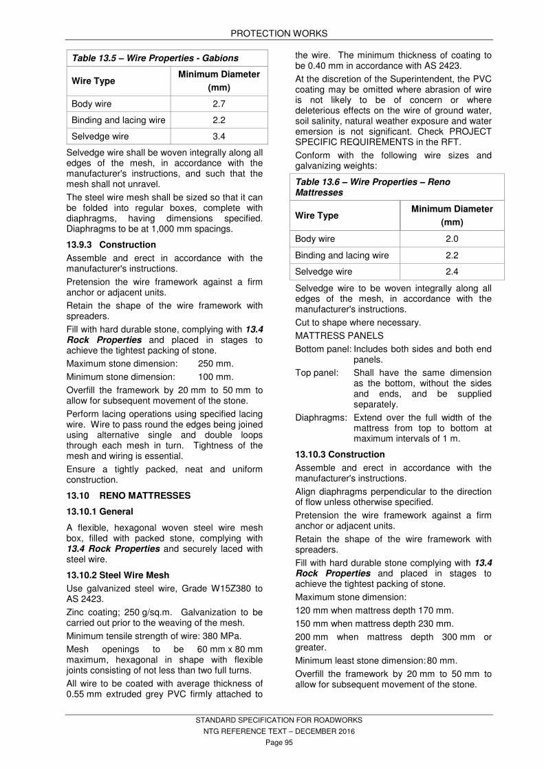
PROTECTION WORKS
STANDARD SPECIFICATION FOR ROADWORKS
NTG REFERENCE TEXT – DECEMBER 2016
Page 95
Table 13.5 – Wire Properties - Gabions
Wire Type Minimum Diameter
(mm)
Body wire 2.7
Binding and lacing wire 2.2
Selvedge wire 3.4
Selvedge wire shall be woven integrally along all edges of the mesh, in accordance with the manufacturer's instructions, and such that the mesh shall not unravel.
The steel wire mesh shall be sized so that it can be folded into regular boxes, complete with diaphragms, having dimensions specified. Diaphragms to be at 1,000 mm spacings.
13.9.3 Construction
Assemble and erect in accordance with the manufacturer's instructions.
Pretension the wire framework against a firm anchor or adjacent units.
Retain the shape of the wire framework with spreaders.
Fill with hard durable stone, complying with 13.4 Rock Properties and placed in stages to achieve the tightest packing of stone.
Maximum stone dimension: 250 mm.
Minimum stone dimension: 100 mm.
Overfill the framework by 20 mm to 50 mm to allow for subsequent movement of the stone.
Perform lacing operations using specified lacing wire. Wire to pass round the edges being joined using alternative single and double loops through each mesh in turn. Tightness of the mesh and wiring is essential.
Ensure a tightly packed, neat and uniform construction.
13.10 RENO MATTRESSES
13.10.1 General
A flexible, hexagonal woven steel wire mesh box, filled with packed stone, complying with 13.4 Rock Properties and securely laced with steel wire.
13.10.2 Steel Wire Mesh
Use galvanized steel wire, Grade W15Z380 to AS 2423.
Zinc coating; 250 g/sq.m. Galvanization to be carried out prior to the weaving of the mesh.
Minimum tensile strength of wire: 380 MPa.
Mesh openings to be 60 mm x 80 mm maximum, hexagonal in shape with flexible joints consisting of not less than two full turns.
All wire to be coated with average thickness of 0.55 mm extruded grey PVC firmly attached to
the wire. The minimum thickness of coating to be 0.40 mm in accordance with AS 2423.
At the discretion of the Superintendent, the PVC coating may be omitted where abrasion of wire is not likely to be of concern or where deleterious effects on the wire of ground water, soil salinity, natural weather exposure and water emersion is not significant. Check PROJECT SPECIFIC REQUIREMENTS in the RFT.
Conform with the following wire sizes and galvanizing weights:
Table 13.6 – Wire Properties – Reno Mattresses
Wire Type Minimum Diameter
(mm)
Body wire 2.0
Binding and lacing wire 2.2
Selvedge wire 2.4
Selvedge wire to be woven integrally along all edges of the mesh, in accordance with the manufacturer's instructions.
Cut to shape where necessary.
MATTRESS PANELS
Bottom panel: Includes both sides and both end panels.
Top panel: Shall have the same dimension as the bottom, without the sides and ends, and be supplied separately.
Diaphragms: Extend over the full width of the mattress from top to bottom at maximum intervals of 1 m.
13.10.3 Construction
Assemble and erect in accordance with the manufacturer's instructions.
Align diaphragms perpendicular to the direction of flow unless otherwise specified.
Pretension the wire framework against a firm anchor or adjacent units.
Retain the shape of the wire framework with spreaders.
Fill with hard durable stone complying with 13.4 Rock Properties and placed in stages to achieve the tightest packing of stone.
Maximum stone dimension:
120 mm when mattress depth 170 mm.
150 mm when mattress depth 230 mm.
200 mm when mattress depth 300 mm or greater.
Minimum least stone dimension: 80 mm.
Overfill the framework by 20 mm to 50 mm to allow for subsequent movement of the stone.

PROTECTION WORKS
STANDARD SPECIFICATION FOR ROADWORKS
NTG REFERENCE TEXT – DECEMBER 2016
Page 96
Perform lacing operations using specified lacing wire. Wire to pass round the edges being joined using alternative single and double loops through each mesh in turn. Tightness of the mesh and wiring is essential.
Last panel on downstream side, or at base of slope, shall be a whole unit (i.e. not cut).
Ensure a tightly packed, neat and uniform construction.
13.11 REVETMENT MATTRESSES
13.11.1 General
A nylon fabric material filled with mortar with filter points for the relief of hydrostatic uplift pressure.
Conform to the manufacturer's instructions.
13.11.2 Materials
Mortar mix proportions:
Table 13.7 – Mortar Mix Proportions – Revetment Mattresses
Cement Type GP
or GB
Fine Sand
Coarse Sand
Water
1 (500kg) 1.2
(600kg) 2.2
(1,100kg) 450 l/m
3
Adjust fine sand/coarse sand proportions if required to provide workable mix.
13.11.3 Construction
Toe-in to provide cut-off walls minimum 300 mm deep and width not less than maximum thickness of mattress.
Lay, cut and stitch mattress on prepared surface. Make allowance for take up of fabric resulting from filling mattress with mortar.
All stitching and seams to be neat in appearance and strength to withstand filling pressure.
Ensure mattress is anchored prior to mortar pumping to prevent creep during placement of mortar.
Provide openings in fabric at a maximum of one every 50 sq.m for placement of mortar. Opening to match size of pumping hose.
Make good openings on completion of mortar pumping.
All areas of mattress to be hard filled with mortar with smooth surface.
Do not permit any loading on the mattress until one hour after mortar pumping has been completed.
Remove spilt mortar from surface of mattress by hand only. Do not use water to wash spilt mortar.
Make good any defective areas.
13.12 EMBANKMENT PROTECTION - CONCRETE
Construct embankment protection from concrete reinforced with a single layer of centrally located SL62 mesh.
Overlap the mesh by 200 mm at joints.
Make construction joints in the vertical plane, at 2 m maximum spacing.
Continue reinforcement mesh across construction joints.
Where margins are required, construct the embankment protection and the margins as an integral unit.
Where there are adjacent protection works, construct the toe of the embankment protection and the adjacent protection work as an integral unit.
Drainage holes to be 75 mm diameter penetrating the full thickness of the protection works. Install the drainage holes at 3 m intervals just above the toe.
Install additional rows of drainage holes parallel to the first, and at 3 m intervals and spacings, where the scope of work requires it.
The exposed surface to be within 50 mm of the specified position.
13.13 MARGINS
Construct margins with reinforced concrete. Conforming to the requirements of MISCELLANEOUS CONCRETE WORKS.
Make construction joints at 3 m maximum spacing.
Form the top 75 mm of the vertical face nearer the pavement, and any exposed outer face, true to line and level.
Wood float and broom finish the upper surface of the margin. Finish flush with the top of the pavement.
Where adjacent pavement is sealed, overlap the bituminous seal on the margins by not less than 100 mm.
TOLERANCES
Width: Not less than specified.
Level: + or – 10 mm of top of adjacent pavement.
13.14 OTHER REQUIREMENTS
Refer to PROJECT SPECIFIC REQUIREMENTS in the RFT.

ROAD FURNITURE AND TRAFFIC CONTROL DEVICES
STANDARD SPECIFICATION FOR ROADWORKS
NTG REFERENCE TEXT – DECEMBER 2016
Page 97
14 ROAD FURNITURE AND TRAFFIC CONTROL DEVICES
14.1 STANDARDS
Conform to the following Standards and Publication unless specified otherwise:
AS 1012(set) Methods of testing concrete AS 1074 Steel tubes and tubulars for
ordinary services AS/NZS 1111(set) ISO metric hexagon
commercial bolts and screws Set
AS/NZS 1112(set) ISO metric hexagon nuts, Including thin nuts, slotted nuts and castle nuts Set
AS 1273 Unplasticised PVC (UPVC) downpipe and fittings for rainwater
AS 1397 Steel sheet and strip hot dipped zinc coated or aluminium/zinc coated
AS/NZS 1554(set) Structural steel welding (Set) AS/NZS 1594 Hot rolled steel flat products AS 1604.1 Specification for preservative
treatment – Sawn and round timber
AS 1722 Pipe threads of whitworth form
AS 1725(set) Chain link fabric fencing AS/NZS 1734 Aluminium and aluminium
alloys - Flat sheet, coiled sheet and plate
AS 1742(set) Manual of uniform traffic control devices
AS 1743 Road signs – Specifications AS 1744 Standard alphabet for road
signs AS/NZS 1906.1 Retroreflective materials and
devices for road traffic control purposes – Retroreflective sheeting
AS 2423 Coated steel wire fencing products for terrestrial, aquatic and general use
AS/NZS 3750.9 Paints for steel structures - Organic zinc-rich primer
AS/NZS 3845.1 Road safety barrier systems and devices - Road safety barrier systems
AS/NZS 4680 Hot dip galvanized (zinc) coatings on fabricated ferrous articles
APAS 1441/1 Permanent graffiti barrier, clear, exterior
APAS 1442/1 Temporary graffiti barrier, clear, exterior
APAS 1443 Graffiti Remover
14.2 DEFINITIONS CS and C(S): Civil Standard drawing. Use the
latest version unless specified otherwise.
GRAFFITI: The name for images or
lettering scratched, scrawled, painted or marked
in any manner on property.
LONGITUDINAL LINES: Any line which
runs parallel to the road centre line, e.g. broken
line, edge line, separation line, barrier line.
OTHER MARKINGS: All diagonal lines,
chevron markings and messages on the
pavement, including symbols, words, numerals,
arrows and kerb markings.
TRAFFIC CONTROL DEVICE: Any sign, signal, pavement marking or other installation placed or erected for the purpose of regulating, warning, guiding or providing for the safety of road users. It does not include temporary warning devices and control measures erected only for the construction period. TRANSVERSE MARKINGS: Any line which
is at right angles to the centre line of the road,
e.g. stop line, hold line, pedestrian cross walk
14.3 FENCING
14.3.1 General
Clearing fence lines includes the removal of trees, shrubs, vegetable matter and debris. Grub out all roots that interfere with the placement of posts.
Erect fences so that the line of the tops of the posts is uniform.
Adjust the position of posts to compensate for the irregularities of the ground.
Provide gates where specified and across existing access tracks or roads.
14.3.2 Existing Fences
Install a post at the intersection of new fence with existing fence and fix the wiring of both fences to that post.
Complete the necessary sections of new fencing before removing or opening a boundary or internal fence.
Obtain the owners agreement to the proposed fence removal and advise the owner or occupier in writing of the date the fence will be removed.
Erect gates or grids at fence openings as specified.
14.3.3 Materials
Barbed wire: 1.57 mm diameter minimum, high tensile.
Plain wire: 2.50 mm diameter minimum, high tensile.
Wire mesh: Galvanized 3.15 mm diameter x 50 mm chain mesh.
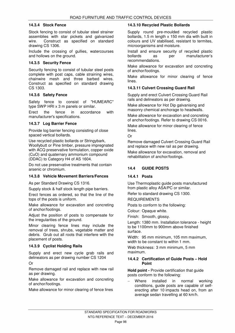
ROAD FURNITURE AND TRAFFIC CONTROL DEVICES
STANDARD SPECIFICATION FOR ROADWORKS
NTG REFERENCE TEXT – DECEMBER 2016
Page 98
14.3.4 Stock Fence
Stock fencing to consist of tubular steel strainer assemblies with star pickets and galvanized wire. Construct as specified on standard drawing CS 1306.
Include the crossing of gullies, watercourses and hollows on the ground.
14.3.5 Security Fence
Security fencing to consist of tubular steel posts complete with post caps, cable straining wires, chainwire mesh and three barbed wires. Construct as specified on standard drawing CS 1303.
14.3.6 Safety Fence
Safety fence to consist of "HUMEARC" type SWP HRI x 3 m panels or similar.
Erect the fence in accordance with manufacturer's specifications.
14.3.7 Log Barrier Fence
Provide log barrier fencing consisting of close spaced vertical bollards.
Use recycled plastic bollards or Stringybark, Woollybutt or Pine timber, pressure impregnated with ACQ preservative formulation, copper oxide (CuO) and quaternary ammonium compound (DDAC) to Category H4 of AS 1604.
Do not use preservative treatments that contain arsenic or chromium.
14.3.8 Vehicle Movement Barriers/Fences
As per Standard Drawing CS 1316.
Supply stock & half stock length pipe barriers.
Erect fences as ordered, so that the line of the tops of the posts is uniform.
Make allowance for excavation and concreting of anchor/footings.
Adjust the position of posts to compensate for the irregularities of the ground.
Minor clearing fence lines may include the removal of trees, shrubs, vegetable matter and debris. Grub out all roots that interfere with the placement of posts.
14.3.9 Cyclist Holding Rails
Supply and erect new cycle grab rails and delineators as per drawing number CS 1204
Or
Remove damaged rail and replace with new rail as per drawing.
Make allowance for excavation and concreting of anchor/footings.
Make allowance for minor clearing of fence lines
14.3.10 Recycled Plastic Bollards
Supply round pre-moulded recycled plastic bollards, 1.5 m length x 150 mm dia with built in colours and UV stabilised, resistant to termites, microorganisms and moisture.
Install and ensure security of recycled plastic bollards as per manufacturer’s recommendations.
Make allowance for excavation and concreting of anchor/footings.
Make allowance for minor clearing of fence lines.
14.3.11 Culvert Crossing Guard Rail
Supply and erect Culvert Crossing Guard Rail rails and delineators as per drawing.
Make allowance for Hot Dip galvanising and masonry chemical anchorage to headwalls.
Make allowance for excavation and concreting of anchor/footings. Refer to drawing CS 0016.
Make allowance for minor clearing of fence lines.
Or
Remove damaged Culvert Crossing Guard Rail and replace with new rail as per drawing.
Make allowance for excavation, removal and rehabilitation of anchor/footings.
14.4 GUIDE POSTS
14.4.1 Posts
Use Thermoplastic guide posts manufactured from plastic alloy ASA/PC or similar.
Refer to standard drawing CS 1300.
REQUIREMENTS
Posts to conform to the following:
Colour: Opaque white.
Finish: Smooth, glossy.
Length: 1380 mm. Installation tolerance - height to be 1100mm to 900mm above finished surface.
Width: 95 mm minimum, 105 mm maximum, width to be constant to within 1 mm.
Web thickness: 3 mm minimum, 5 mm maximum.
14.4.2 Certification of Guide Posts – Hold Point
Hold point - Provide certification that guide posts conform to the following:
− Where installed in normal working conditions, guide posts are capable of self-erecting after 10 impacts head on, from an average sedan travelling at 60 km/h.

ROAD FURNITURE AND TRAFFIC CONTROL DEVICES
STANDARD SPECIFICATION FOR ROADWORKS
NTG REFERENCE TEXT – DECEMBER 2016
Page 99
− After 2,000 hours of exposure in an Atlas Weatherometer the guide posts do not change colour by more than 10 points on a Delta E colour chart.
− The guide post material has a minimum Vicat softening point of 120ºC.
− Physical testing as specified.
− Resistant to termites.
14.4.3 Guide Post Characteristics – Hold Point
Provide guide posts which have the following:
− An anti-withdrawal device which will prevent the guide post from being withdrawn without dislodgement of the compacted backfill. Anti-withdrawal devices must be engaged on each and every guide post prior to installation of guide posts.
− Legible and indelible markings similar to those used to mark or uPVC sewer and water pipes, in letters no less than 5 mm high, showing month and year of manufacture and located approximately 400 mm from the top of the post. Stick-on labels are not permitted.
− Legible and indelible marking 380 mm from the bottom of the guide post, to indicate depth for installation. Stick-on labels are not permitted.
Hold point - Provide a sample guide post from each batch purchased for this contract for approval before installing any guide posts.
14.4.4 Delineators
RECTANGULAR RETROREFLECTORS
To be of Class 1A retroreflective material.
Size to be 200 mm x 50 mm for red delineators; and for white delineators. Area minimum 100 cm
2 (10,000 mm
2).
DISCRETE DEVICE TYPE RETROREFLECTORS
Maximum projected face area for red delineator devices and white delineator devices to be 100 cm
2 (10,000 mm
2). Minimum length of
shortest projected dimension to be 60 mm.
14.4.5 Installation
Attach one red and one white delineator to each guide post, 50 mm from the top of the post.
The red delineator to be attached to the convex side of curved guide posts where applicable.
Attach any discrete device type retroreflectors required as specified.
Red delineators to be on the left and white delineators to be on the right when viewed in the direction of travel.
14.5 ROAD SIGNS
14.5.1 General
This subsection specifies the manufacture, supply, delivery and erection of road signs.
14.5.2 Materials – Hold Point
NON-REFLECTIVE MATERIALS
In accordance with AS 1743.
REFLECTIVE MATERIAL
Use high intensity Class 1 standard in accordance with AS/NZS 1906.1 for all signs, including temporary signs, and hazard markers with the exception that all black legends are to be non-reflective.
BLANKS
Use aluminium marine grade alloy designation 5052 - H38. Thickness 1.6 mm.
Steel sheets may only be used for temporary signs.
MANUFACTURE
Chemically clean aluminium blanks before painting or bonding of reflective material.
Stamp the month and year of manufacture and the symbol DIPL on the backs of all signs.
POSTS
Post sizes to conform to Table 14.3 – Roadside Signs – Mounting Selection – Part 1 of 2 at 14.9 - Tables unless specified otherwise. See PROJECT SPECIFIC REQUIREMENTS in the RFT.
Posts to be medium grade galvanized pipe with plain ends and constructed from a single length of pipe. Cap each post with a galvanized cap. Do not use “Ingal” posts.
Standard; to AS 1074.
ANTI-GRAFFITI COATING
Hold Point – Obtain Superintendent’s approval for the use of anti-graffiti film or coating products. Apply anti-graffiti products only to the new road signs specified by the Superintendent.
14.5.3 Supply and Delivery
Supply all brackets, bolts, nuts and bracings.
Fix bracings to the signs prior to delivery.
14.5.4 Location
Signs to be located clear of vegetation and be clearly visible under headlight illumination.
LATERAL PLACEMENT
Lateral placement to be measured to the edge of the sign nearest the road. Lateral placement to be as follows: Unkerbed roads: 2 to 4 m clear from the edge of the traffic lane, and 600 mm minimum clear from the outer edge of the road shoulder.
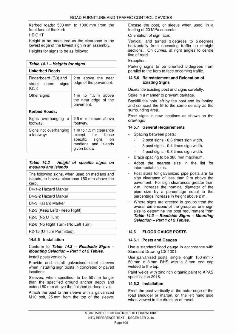
ROAD FURNITURE AND TRAFFIC CONTROL DEVICES
STANDARD SPECIFICATION FOR ROADWORKS
NTG REFERENCE TEXT – DECEMBER 2016
Page 100
Kerbed roads: 500 mm to 1000 mm from the front face of the kerb.
HEIGHT
Height to be measured as the clearance to the lowest edge of the lowest sign in an assembly.
Heights for signs to be as follows:
Table 14.1 – Heights for signs
Unkerbed Roads
Fingerboard (G3) and
street name signs (G5):
2 m above the near edge of the pavement.
Other signs: 1 m to 1.5 m above the near edge of the pavement.
Kerbed Roads:
Signs overhanging a footway:
2.5 m minimum above footway.
Signs not overhanging a footway:
1 m to 1.5 m clearance except for those specific signs on medians and islands given below.
Table 14.2 – Height of specific signs on medians and islands
The following signs, when used on medians and islands, to have a clearance 150 mm above the kerb:
D4-1-2 Hazard Marker
D4-2-2 Hazard Marker
D4-3 Hazard Marker
R2-3 (Keep Left) (Keep Right)
R2-5 (No U Turn)
R2-6 (No Right Turn) (No Left Turn)
R2-15 (U Turn Permitted).
14.5.5 Installation
Conform to Table 14.3 – Roadside Signs – Mounting Selection – Part 1 of 2 Tables.
Install posts vertically.
Provide and install galvanised steel sleeves when installing sign posts in concreted or paved locations.
Sleeves, when specified, to be 50 mm longer than the specified ground anchor depth and extend 50 mm above the finished surface level.
Attach the post to the sleeve with a galvanized M10 bolt, 25 mm from the top of the sleeve.
Encase the post, or sleeve when used, in a footing of 20 MPa concrete.
Orientation of sign face:
Vertical, and turned 3 degrees to 5 degrees horizontally from oncoming traffic on straight sections. On curves, at right angles to centre line of road.
Exception:
Parking signs to be oriented 5 degrees from parallel to the kerb to face oncoming traffic.
14.5.6 Reinstatement and Relocation of Existing Signs
Dismantle existing post and signs carefully.
Store in a manner to prevent damage.
Backfill the hole left by the post and its footing and compact the fill to the same density as the surrounding area.
Erect signs in new locations as shown on the drawings.
14.5.7 General Requirements
- Spacing between posts:
- 2 post signs - 0.6 times sign width.
- 3 post signs - 0.4 times sign width.
- 4 post signs - 0.3 times sign width.
- Brace spacing to be 380 mm maximum.
- Adopt the nearest size in the list for intermediate sizes.
- Post sizes for galvanized pipe posts are for sign clearance of less than 2 m above the pavement. For sign clearances greater than 2 m, increase the nominal diameter of the pipe size by a percentage equal to the percentage increase in height above 2 m.
- Where signs are erected in groups treat the overall dimensions of the group as one sign size to determine the post requirement from Table 14.3 – Roadside Signs – Mounting Selection – Part 1 of 2 Tables.
14.6 FLOOD GAUGE POSTS
14.6.1 Posts and Gauges
Use a standard flood gauge in accordance with Standard Drawing CS 1301.
Use galvanized posts, single length 150 mm x 50 mm x 3 mm RHS with a 3 mm end cap welded to the top.
Paint welds with zinc rich organic paint to APAS specification 2916.
14.6.2 Installation
Erect the post vertically at the outer edge of the road shoulder or margin, on the left hand side when viewed in the direction of travel.

ROAD FURNITURE AND TRAFFIC CONTROL DEVICES
STANDARD SPECIFICATION FOR ROADWORKS
NTG REFERENCE TEXT – DECEMBER 2016
Page 101
Install a concrete anchor, of 20 MPa concrete, with a depth of 650 mm and a diameter of 300 mm.
Cast a suitable galvanized sleeve, 650 mm in length, in the anchor so that the sleeve extends 50 mm above the finished surface level.
Attach post to sleeve with a galvanized M10 bolt 25 mm from the top of the sleeve.
Secure gauge to post with No 10 galvanized Tek screws or 4 mm blind pop rivets at 300 mm centres staggered alternately each side.
Position gauge zero to comply with lowest spot on floodway along the centre line.
14.7 CATTLE GRIDS
Construct grids to the details shown on the drawings. Refer to standard drawings CS 1306, CS 1313, CS 1314 & CS 1315. Place the grid centre line on the centre line of the road pavement. The grid grade and levels to conform to the grade and levels of the adjacent road pavement. Place and compact select fill behind the abutments of the grid, up to the base of the pavement. Reinstate pavement layers with base material. Reinstate surface. Tighten all hold down bolts as specified. Paint the portion of guardrails above ground with one coat zinc phosphate primer and two coats of white alkyd paint. Fix width markers with epoxy adhesive to each guardrail. Construct strainer post assemblies as specified. Fix the stock fence to the strainer assembly. Supply and install a gate in the fencing adjacent to the grid as specified. Refer to standard drawings CS 1306 and CS 1317.
14.8 STEEL BEAM GUARDRAIL
14.8.1 Materials
Refer to CS 1310. Refer to CIVIL STANDARD DRAWINGS.
RAILS
Use W-beam guardrail to AS/NZS 3845.1 of nominal 300 mm width formed from HA 350 steel to AS/NZS 1594.
Rails to be capable of withstanding a cold bend of 180 deg. around a diameter 2.5 times its own thickness without cracking.
Base metal thickness to be 2.7 mm minimum.
TERMINAL SECTIONS
Form from HA 350 steel having the same properties and thickness as the rails.
POSTS
Fabricate posts and block outs from steel channel section in accordance with standard drawings.
BOLTS AND NUTS
Shape bolt shoulders and holes in rail elements to prevent the bolts from turning.
Length of bolts to be sufficient to extend 6 mm to 12 mm beyond the nuts.
GALVANIZING
Galvanize all components by hot dip galvanizing, after fabrication, to AS/NZS 4680.
Where the galvanising on guard rail or associated fittings has been damaged, the coating shall be repaired by regalvanising or by painting with a minimum of two coats of a zinc-rich inorganic paint in accordance with AS/NZS 3750.9 and one coat of aluminium paint.
COMPLIANCE
Marking of materials - To: AS/NZS 1594
Each coil or shipping unit shall be clearly and durably marked or tagged to indicate the following:
(a) Steel grade designation.
(b) Dimensions.
(c) Name or registered trade name or mark of the manufacturer.
(d) Batch identification.
If the marked portion of the material is subsequently removed then these markings are to be transferred to each remaining portion of the material.
Traceability of components - To: AS/NZS 3845 Part 1
(a) All steel rails, posts and other critical components shall be permanently marked in lettering at least 10 mm high with the name of System Manufacturer, the date and month of manufacture the grade of steel and base metal thickness (BMT) to allow the product to be traced.
(b) Where plastic components make up a key element of the system, they shall be permanently marked clearly indicating the month and year of manufacture in a location that can be easily inspected.
(c) Bolts shall be marked in accordance with AS 1111.1 or AS/NZS 1252.
Certificate(s) of compliance - To: AS/NZS 1594
Provide certificate(s) of compliance from the manufacturer that the steel used in the manufacture of the steel beam guardrails is of structural grade HA 350.
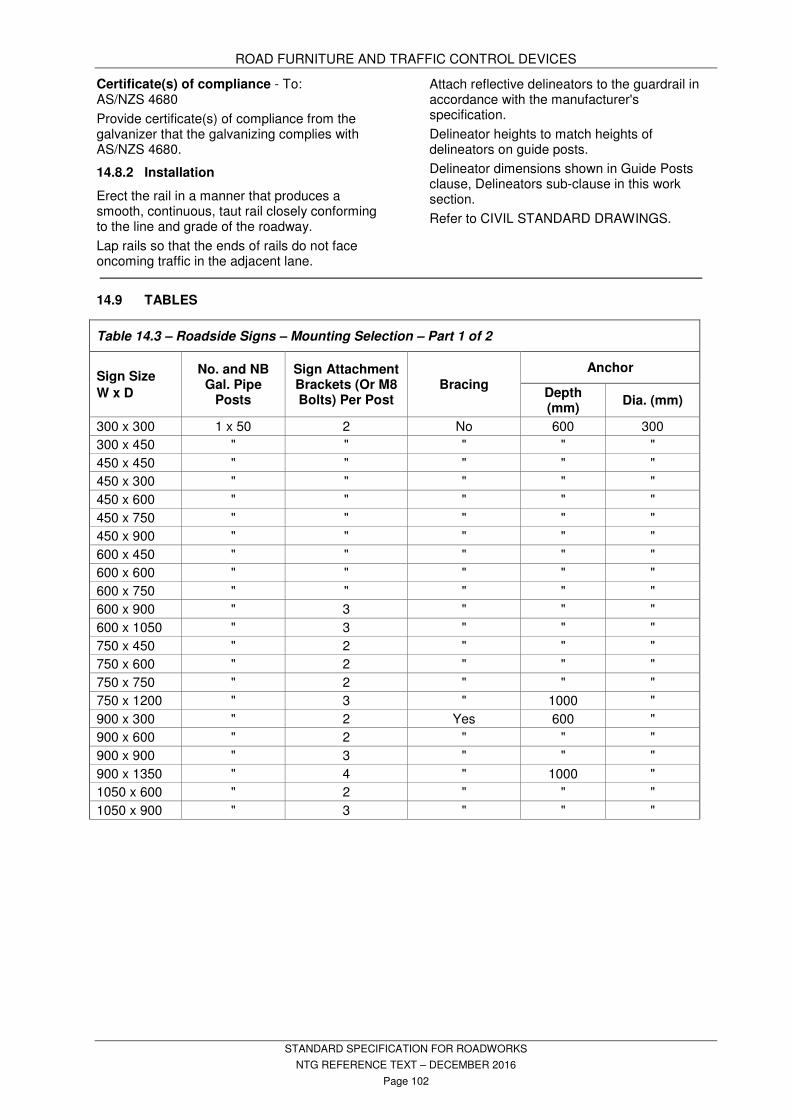
ROAD FURNITURE AND TRAFFIC CONTROL DEVICES
STANDARD SPECIFICATION FOR ROADWORKS
NTG REFERENCE TEXT – DECEMBER 2016
Page 102
Certificate(s) of compliance - To: AS/NZS 4680
Provide certificate(s) of compliance from the galvanizer that the galvanizing complies with AS/NZS 4680.
14.8.2 Installation
Erect the rail in a manner that produces a smooth, continuous, taut rail closely conforming to the line and grade of the roadway.
Lap rails so that the ends of rails do not face oncoming traffic in the adjacent lane.
Attach reflective delineators to the guardrail in accordance with the manufacturer's specification.
Delineator heights to match heights of delineators on guide posts.
Delineator dimensions shown in Guide Posts clause, Delineators sub-clause in this work section.
Refer to CIVIL STANDARD DRAWINGS.
14.9 TABLES
Table 14.3 – Roadside Signs – Mounting Selection – Part 1 of 2
Sign Size
W x D
No. and NB Gal. Pipe
Posts
Sign Attachment Brackets (Or M8 Bolts) Per Post
Bracing
Anchor
Depth (mm)
Dia. (mm)
300 x 300 1 x 50 2 No 600 300
300 x 450 " " " " "
450 x 450 " " " " "
450 x 300 " " " " "
450 x 600 " " " " "
450 x 750 " " " " "
450 x 900 " " " " "
600 x 450 " " " " "
600 x 600 " " " " "
600 x 750 " " " " "
600 x 900 " 3 " " "
600 x 1050 " 3 " " "
750 x 450 " 2 " " "
750 x 600 " 2 " " "
750 x 750 " 2 " " "
750 x 1200 " 3 " 1000 "
900 x 300 " 2 Yes 600 "
900 x 600 " 2 " " "
900 x 900 " 3 " " "
900 x 1350 " 4 " 1000 "
1050 x 600 " 2 " " "
1050 x 900 " 3 " " "

ROAD FURNITURE AND TRAFFIC CONTROL DEVICES
STANDARD SPECIFICATION FOR ROADWORKS
NTG REFERENCE TEXT – DECEMBER 2016
Page 103
Table 14.4 – Roadside Signs – Mounting Selection – Part 2 of 2
Sign Size W x D
No. and NB Gal. Pipe
Posts
Sign Attachment Brackets (Or M8 Bolts) Per Post
Bracing Anchor
Depth (mm)
Dia. (mm)
1200 x 600 2 x 50 2 Yes 600 300
1800 x 600 2 x 50 2 " 1000 "
1800 x 1200 2 x 80 4 " " "
2400 x 1200 2 x 80 4 " 1200 450
2400 x 1800 2 x 100 5 " " "
3000 x 600 2 x 50 2 " 1000 300
3000 x 1200 2 x 80 4 " 1200 450
3000 x 1800 2 x 100 5 " 1500 "
3700 x 600 2 x 80 2 " 1000 300
3700 x 1200 3 x 80 4 " 1200 450
3700 x 1800 3 x 100 5 " 1500 "
3700 x 2400 4 x 100 7 " 1500 "
4300 x 600 2 x 80 2 " 1000 300
4300 x 1200 3 x 80 4 " 1200 450
4300 x 1800 3 x 100 5 " 1500 "
4900 x 600 3 x 80 2 " 1000 300
4900 x 1200 3 x 100 4 " 1200 450
4900 x 1800 3 x 100 5 " 1500 "
5500 x 600 3 x 80 2 " 1000 300
5500 x 1200 3 x 100 4 " 1200 450
5500 x 1800 4 x 100 5 " 1500 "
6100 x 600 3 x 80 2 " 1000 300
6100 x 1200 3 x 100 4 " 1200 450
6100 x 1800 4 x 100 5 " 1500 "
14.10 OTHER REQUIREMENTS
Refer to PROJECT SPECIFIC REQUIREMENTS in the RFT.
PAVEMENT MARKING
STANDARD SPECIFICATION FOR ROADWORKS
NTG REFERENCE TEXT – DECEMBER 2016
Page 104
15 PAVEMENT MARKING
15.1 GENERAL
This section specifies the materials, testing and standards of workmanship for marking of pavements with road marking paint and/or thermoplastic material, including glass beads.
15.2 STANDARDS
Conform to the following Standards and Publication unless specified otherwise:
AS/NZS 1580(set) Paints and related materials - Methods of test
AS/NZS 1580.205.4 - Application properties - Airless spraying
AS 1742(set) Manual of uniform traffic control devices
AS 1744 Standard alphabets for road signs
AS 1906(set) Retroreflective materials and devices for road traffic control purposes
AS/NZS 1906.1 Retroreflective sheeting AS/NZS 2009 Glass beads for road
marking materials AS/NZS 2310 Glossary of paint and
painting terms AS/NZS 2311(set) Guide to the painting of
buildings AS/NZS 2433 Plastics - Method for
exposure to ultraviolet lamps AS 2700 Colour standards for general
purposes AS 3730(set) Guide to properties of paints
for buildings AS/NZS 3750.22 Paints for steel structures –
Full gloss enamel – Solvent-borne
AS 4049.2 Paints and related materials -Thermoplastic pavement marking materials - For use with surface applied glass beads
AS 4049.3 Paints and related materials - Pavement marking materials - Waterborne paint - For use with surface applied glass beads
APAS 0041/4 Road marking paint, thermoplastic
APAS 0041/5 Road marking paint, water borne
APAS 0042 Glass beads for pavement marking paint
NTMTM NT Materials Testing Manual NTTM NT Test Methods
15.3 DEFINITIONS
ATLM
Audio Tactile Line Marking
APAS
Australian Paint Approvals Scheme
CS & C(S)
Civil Standard drawings. Use the most recent version.
LONGLIFE MATERIALS
Generally thermoplastic, cold applied plastic or pliant polymer materials, with life spans between 2 to 5 times that of waterborne paint.
LONGITUDINAL LINES:
Any line which runs parallel to the road centre line, e.g. broken line, edge line, separation line, barrier line.
NTTM
NT Test Methods, found in NT Materials Testing Manual.
OTHER MARKINGS:
All diagonal lines, chevron markings and messages on the pavement, including symbols, words, numerals, arrows and kerb markings.
PCCP
Painting Contractors Certification Program.
RETROREFLECTIVITY
The reflectivity provided by glass beads expressed as minicandela per lux per square metre (mcd/lux/m
2) as measured by a
reflectometer approved by the Superintendent.
TRAFFIC CONTROL DEVICE:
Any sign, signal, pavement marking or other installation placed or erected for the purpose of regulating, warning, guiding or providing for the safety of road users. It does not include temporary warning devices and control measures erected only for the construction period.
TRANSVERSE MARKINGS:
Any line which is at right angles to the centre line of the road, e.g. stop line, hold line, pedestrian cross walk.
15.4 CONTRACTOR ACCREDITATION
All pavement marking work must be carried out by a contractor accredited to the Painting Contractor Certification Program (PCCP) in a class or category applicable to the work. The PCCP is administered by the CSIRO. Information regarding the PCCP can be obtained at http://www.apas.gov.au/pccp/ .

PAVEMENT MARKING
STANDARD SPECIFICATION FOR ROADWORKS
NTG REFERENCE TEXT – DECEMBER 2016
Page 105
15.5 ROAD MARKING PAINT – WITNESS POINT
Road marking paint: Approved water based white road marking paint conforming to APAS 0041/5 and suitable for application by spray equipment in accordance with Test Method AS/NZS 1580.205.4 to asphalt and bituminous seal road surfaces and for use with Intermix drop-on spherical glass beads.
Australian Paint Approvals Scheme (APAS) Specifications: For paint types identified by an APAS specification code, conform to the specification represented by that code.
Witness Point - Submit a Certificate of Compliance in respect to the paint complying with the relevant Australian Standards or APAS specification.
15.6 THERMOPLASTIC MATERIALS
Thermoplastic road marking material must consist of aggregate, pigment, binder, glass beads and extenders, capable of being softened by heating and hardened by cooling.
Thermoplastic road marking materials must comply with AS 4049.2.
15.6.1 Audio Tactile Markings
Thermoplastic used for audio tactile pavement markings must comply with AS 4049.2 but modified as follows:
− Softening Point: When determined in accordance with AS 2341.18 the softening point shall be not less than 95 °C.
− Cold Flow: When determined in accordance with AS 4049.2 Appendix I – Determination of flow resistance - the cold flow shall be no more than 5% at 40 °C.
− Skid Resistance: When tested in accordance with AS 4049.2 Appendix K – Field tests for thermoplastic pavement marking material – and Appendix L – Field determination of skid resistance (wet pendulum method) - at any time up to 3,000,000 vehicle passes, the skid resistance value of beaded unprofiled base material must be not less than 50.
− Retro-reflectivity: Mix glass beads to AS/NZS 2009 Type C into the thermoplastic material at a rate of not less than 30% by mass prior to application.
15.7 COLD APPLIED PLASTIC MATERIALS
15.7.1 Standards
AS 4049.2 Paints and related materials—Pavement marking materials - Part 2:
Thermoplastic pavement marking materials—For use with surface applied glass beads
AS 4049.4 Paints and related materials—Pavement marking materials – Part 4: High performance pavement marking systems
AP-S0041/3 Pavement marking materials – cold applied plastic
AP-S0042 Glass beads for use in pavement marking paints
15.7.2 Materials – Witness Point
Generally: A two part Poly Methyl Methacrylate resin based pavement marking material that complies with the requirements for colour, luminance and bead content of AS 4049.2, and which complies with AS 4049.4, sprayed or screeded onto the pavement, containing pre-mixed glass beads, with additional drop-on beads being added during application, conforming with the following requirements of AS 4049.2: Clause 5.1 – Colour, Clause 5.2 - Luminance and Clause 7 - Field Testing. The material shall have a maximum no-pick-up time of 60 minutes.
Witness Point - Provide evidence that all proprietary products such as epoxy or plastic products have demonstrated satisfactory field performance for a period of at least three years.
15.7.3 Application – Witness Point
Application is to be in accordance with the Manufacturer’s Specification.
Witness Point - Provide evidence that it has been applied in accordance with the Manufacturer’s instructions.
The area to be marked is to be dry and free of dirt, gravel, oil and other loose or foreign material to ensure the best possible adhesion of new material. Remove existing paint or other material which is flaking or chipped. Cleaning may be carried out by brooming, blowing or washing.
Use a tack coat or primer material for surface or other conditions requiring it in accordance with the Manufacturer’s Specification.
Apply by spraying, screeding, trowelling or extrusion methods, including application of glass beads and anti-skid material, in a single uniform layer.
For longitudinal lines and transverse markings, apply material at a rate to achieve a minimum final thickness of 2.5 mm ± 0.5 mm for application by screeding, trowelling or extrusion methods. Glass beads are to be Class C (intermix 20 to 30 % by mass) and Class D. As well as the “mixed in” glass beads additional Class D beads shall be uniformly applied to the surface of thermoplastic at the rate of 0.40

PAVEMENT MARKING
STANDARD SPECIFICATION FOR ROADWORKS
NTG REFERENCE TEXT – DECEMBER 2016
Page 106
kg/m2 as part of the application process and before the material has commenced to set.
The marking produced shall be uniform in texture, width and thickness and the surface substantially free from blisters, streaks, lumps and other defects.
Remove any occurrence of overspray and gun dribble.
15.7.4 Setting out
The location of all pavement markings on new surfaces, including reflective raised pavement markers, shall be set out by spotting with paint or other approved method prior to application of the markings.
The location of all pavement markings over existing markings shall match the existing except where directed otherwise.
For continuous thermoplastic pavement marking, 50 mm drainage gaps shall be provided, at a maximum spacing of 6m +1m, to allow adequate drainage of the pavement surface. Nominate in the Contract Management Plan the method of identifying the location and spacing for these gaps.
15.8 GLASS BEADS – WITNESS POINT
Use Type C (Intermix) glass beads conforming to AS/NZS 2009 and APAS specification 0042 with the exception of size, and conforming to the size distribution requirements in Table 15.1 – Glass Beads Size Distribution.
Witness Point - Submit a Certificate of Compliance in respect to the glass beads complying with the relevant Australian Standard and APAS specification.
Table 15.1 – Glass Beads Size Distribution
Sieve Size (Microns)
% Retained % Passing
1180 0 – 3 97 – 100
850 5 – 20 80 - 95
425 65 – 95 5 – 35
Pan 0 - 10 -
15.9 SETTING OUT
New work: Set out line marking to the line pattern specified in accordance with the standard drawing for line marking, CS 1520 and in accordance with AS 1742 including the setting out of arrows, letters, numerals and chevrons.
Remarking: Remark along the line of the existing line marking and to the tolerances specified for new work.
15.10 APPLICATION – WITNESS POINT
Equipment: Apply the marking materials using a self-propelled mobile sprayer, hand sprayer, hand painting or hand screeding as directed by the Superintendent.
Witness Point - Obtain approval from the Superintendent for the type of equipment to be used for applying pavement marking materials.
Witness Point - Produce documented evidence to show that the spraying equipment has been calibrated in accordance with NTTM 405.1.
Maximum application speed for Intermix glass beads is 12 km/h.
Apply glass beads by low pressure or delivered by gravity dispenser.
The application rates specified for glass beads are the amounts that are retained in the painted surface after 3 weeks of trafficking.
Produce markings free from ghosting and raggedness on the sides and ends and parallel with the general alignment of the carriageway with the lines level, uniform and free from streaks.
Substrate: Ensure that the road surface is free from dirt, loose detritus, mud and other extraneous matter, and is dry before and after painting operations.
15.10.1 Longitudinal Application
Apply paint evenly to the road surface at the specified film thicknesses (Tolerance + 0.05 mm) and not more than five seconds after spraying apply the intermix glass beads. Ensure that the loss in glass beads after three weeks traffic does not exceed ten per cent of total applied.
On all work, apply one coat of paint and glass beads to the road in the direction of traffic flow, where possible.
For remarking, apply one coat of paint and glass beads to the surface in the direction of traffic flow, where possible.

PAVEMENT MARKING
STANDARD SPECIFICATION FOR ROADWORKS
NTG REFERENCE TEXT – DECEMBER 2016
Page 107
Table 15.2 – Application Rates – Road Markings
Material Longitudinal
Markings
Transverse and Other
Markings
Water borne Paint dry film thickness (excluding surface applied beads)
> 0.250 mm > 0.250 mm
Water borne Paint wet film thickness (excluding surface applied beads)
> 0.400 mm > 0.400 mm
Surface applied glass beads
(rate retained in the paint surface)
Intermix glass beads
> 300g/m2
Intermix glass beads
> 300g/m2
Thermoplastic cold film thickness > 1.5 mm 3.0 mm + 1.0 mm
Surface applied glass beads
(rate retained in the painted surface)
Intermix glass beads
> 300g/m2
Intermix glass beads
> 300g/m2
15.10.2 Transverse and Other Marking Applications
Apply paint evenly to the road surface to the specified film thickness and immediately after apply an even application of ‘drop-on’ glass beads at the specified rates.
15.11 TOLERANCE
Ensure the distance between the centre line of the marking and the centre line of the set out mark is less than 30 mm. The apparent line of the markings is a smooth continuous alignment when viewed in the direction of the line. Permitted tolerance for the length, width and spacing of all pavement markings: +/- 10 mm.
15.12 WORKMANSHIP – HOLD POINT
Set out markings so that they are straight, with smooth even curves where necessary. Remove any marking material beyond the defined marking leaving a neat and smooth marking on the pavement.
Hold Point - Remove defective marking by sand blasting, or other approved methods, make good the surface in a manner approved by the Superintendent.
Protect all applications from traffic until the binder has hardened sufficiently to retain the glass beads.
Reinstate pavement markings that are damaged by traffic during paint drying time and remove all tyre pickup marks.
15.13 FIELD TESTING
Wet film thickness: Check the thickness of the wet film applied to the road pavement by the method of procedure for Operation of Wet Film Thickness Comb (NTTM 401.1).
Glass bead application: Check the application rate of glass beads to the surface of the marked line by the method of Field Procedure for Measurement of the Rate of Application of Spherical Glass Beads (NTTM 402.1).
Wear assessment limits: The degree of wear is defined as the area of pavement marking remaining after a period of time, relative to the initial area of the pavement marking.
Degree of wear: At the Superintendent’s discretion determine the degree of wear using Image Analysis in accordance with AS 4049.3 Appendix K, Method A, Photographic Method.
Wear limits for pavement marking: 95% intact area after six months.
Remark pavement marking that does not conform to the specified limits at the Contractor’s expense including the costs of all testing.
15.14 RESEALING CONTRACTS
Conform to the requirements set out in this section and to the following requirements for resealing work including enrichments, spray sealing, rejuvenation and emulsion coats.
15.14.1 Panel Contractors
The Principal has in place a Panel Contract with approved line marking companies.
The selection of the Panel Contractors for particular contracts is made on a rotating basis and the Superintendent will advise of the name and contact details of the Panel Contractor to be used on this contract.
The Principal will pay the Panel Contractor direct for the pavement marking work.

PAVEMENT MARKING
STANDARD SPECIFICATION FOR ROADWORKS
NTG REFERENCE TEXT – DECEMBER 2016
Page 108
15.14.2 Co-ordination of Pavement Marking Work
The Contractor is responsible for co-ordination of the pavement marking work.
Make all arrangements necessary with the pavement marking Panel Contractor to meet the following requirements:
- For urban work, complete the pavement marking within two days of resealing work.
- For rural work, complete the pavement marking within four days of resealing work.
Retain all traffic control and warning devices necessary until pavement marking is completed.
Record all localities and extent of pavement marking to reinstate to existing arrangements. Provide this information to the panel contract line marker and co-ordinate all pavement marking works.
15.15 AUDIO TACTILE LINE MARKING (ATLM)
15.15.1 Site Preparation
Immediately prior to marking application, remove all extraneous or loose material from areas where the thermoplastic material is to be applied. Prepare and prime areas as
recommended by the manufacturer to ensure satisfactory adhesion of thermoplastic material.
15.15.2 Application
Apply ATLM directly on to the road surface on existing painted edge lines or centre double barrier lines.
Apply markings within the tolerances specified in Table 15.3- Audio Tactile Line Marking Tolerances. The height of the thermoplastic raised ribs is measured from the planed surface formed by the tops of the aggregate.
15.15.3 Retro-reflectivity
Apply glass beads in accordance with AS 2009 Type B immediately to the surface of the molten thermoplastic material. The minimum rate to be retained on the thermoplastic material is 200 g/m
2.
When tested in accordance with AS 4049.2 Appendix K - Field tests for thermoplastic pavement marking material – and Appendix M – Determination of retroreflectivity , marking must achieve a minimum level of reflectivity of 350 mcd/lux/m
2 at time of application.
Table 15.3- Audio Tactile Line Marking Tolerances
Aspect Dimension Tolerance (mm)
Height of raised rib 8mm +2mm or -1mm
Spacing of raised rib 250mm ± 10mm
Length of raised rib 50mm ± 2mm
Slope of raised rib 45 degrees ± 10 degrees
Width of raised rib (edge line). As shown on project drawings. Otherwise 100mm
± 2mm
Width of raised rib (centre barrier line) 80mm ± 2mm
15.16 RAISED RETROREFLECTIVE PAVEMENT MARKERS (RRPMS)
15.16.1 Materials
Use STIMSONITE 953 markers fixed to the road surface as recommended by the manufacturer of the marker. Use adhesives as recommended by the manufacturer. Use adhesives within the time recommended by the adhesive manufacturer.
15.16.2 Pavement Preparation
Ensure each RRPM site is free of dirt, oil, grease, paint and any other material which
would affect the bond of adhesive to the pavement. Abrasive blast, chip, or burn pavements that cannot be cleaned by sweeping. Check the moisture content of the surface immediately before application by the polyethylene film moisture test. Do not place markers if the film moisture test indicates the presence of moisture.
15.16.3 Placing Markers
Place markers in accordance with the manufacturer's directions. Use marker types as follows: - Centre line: White, two way reflectors.
PAVEMENT MARKING
STANDARD SPECIFICATION FOR ROADWORKS
NTG REFERENCE TEXT – DECEMBER 2016
Page 109
- Lane line: White, one way reflectors. - Left edge line: Red, one way reflectors. - Right edge line adjacent to medians on
dual carriageway: Red, one way reflectors. - Chevron areas:. Yellow, one way reflectors
or yellow, two way reflectors. - Roads: Yellow, one way reflectors. Place the reflectors to face the oncoming traffic. Do not obscure the reflective faces by adhesive. Ensure that the surface finish is smooth. Discard markers which are not positioned correctly within the time recommended by the manufacturer for use of the adhesive. Remove adhesive from the road surface. Do not place markers over joints in concrete pavement. For reseal works where the existing seal has excess binder, or where Gilsabind is used: - Clean the road surface to expose the
aggregate prior to installation of RRPMs. - Protect the RRPMs from traffic until the
adhesive is fully set. - Locate the RRPMs to the outside of edge
lines.
15.17 REMOVAL OF EXISTING MARKINGS – HOLD POINT
Hold Point – Obtain approval from the Superintendent on the method used for line marking removal. Removal of pavement marking must not adversely affect the integrity of the road surface. When arrows, letters or figures are to be removed or temporarily blacked out, the removal pattern must be in the shape of a rectangle or square to minimise confusion to the motorist, particularly in wet weather or poor lighting conditions. Remove all materials and debris from removal operations and dispose at an authorised disposal site. Repair any surface defect caused by the removal process at no additional cost to the Principal.. The following methods may be considered and will be dependent on the type of surface, extent and application.
15.17.1 Machine Grinding
This method may be considered for use on smaller removal jobs where surface finish is not a concern. Can be used on most asphalt and concrete surfaces.
15.17.2 Sandblasting
Sandblasting is the preferred method for marking removal on asphalt and concrete surfaces. Use a skirt or guard around the blaster to minimise the spraying of material away from the immediate work area. Remove waste material before it can be transported by rain, wind or traffic. This will
generally require the use of a vacuum attachment operating concurrently with the blasting operation or alternative method approved by the Superintendent.
15.17.3 Sealing
Spray sealing is the preferred method for sprayed seal surfaces. Conform to specification requirements covered under SPRAY SEALING FOR MAINTENANCE in the Standard Specification for Road Maintenance.
15.17.4 Paint Blackout
Paint blackout may be considered as a temporary measure only as markings retain a high reflection and possess low skid resistance.
15.17.5 Other Methods
Other methods such as water blasting, heat lance or paint stripping may also be considered by the Superintendent.
15.17.6 Raised Reflective Pavement Marker Removal
Where required, remove raised pavement markers by breaking the bond between the adhesive, the road surface and the base of the raised pavement marker.
Repair all divots caused by the removal of raised pavement markers with hot melt adhesive or epoxy adhesive to the level of the surrounding pavement.
15.18 OTHER REQUIREMENTS
Refer to PROJECT SPECIFIC REQUIREMENTS in the RFT.

LANDSCAPE
STANDARD SPECIFICATION FOR ROADWORKS
NTG REFERENCE TEXT – DECEMBER 2016
Page 110
16 LANDSCAPE
16.1 STANDARDS
Conform to the following Publications unless specified otherwise:
AS/NZS 3500 Plumbing and drainage AS 4373 Pruning of amenity trees AS 4419 Soils for landscaping and
garden use. AS 4454 Composts, soil conditioners and
mulches Specification Reference Refer to the Northern Territory Government Standard Specification for Environmental Management and to the RFT. Defects liability period for landscape works is to be a minimum of 13 weeks from practical completion of the entirety of the works under the contract, or the same as the defects liability period for the entirety of the works if that period of time is longer or finishes later. Refer to PROJECT SPECIFIC REQUIREMENTS in the RFT.
16.2 DEFINITIONS
CERTIFIED SEED:
Seed by record of origin, purity, and strain and conforming in character to the parent stock.
EXOTIC PLANTS:
Any plants not native to Australia.
FINE TILTH:
The friable soil resulting from cultivation.
GERMINATION PERCENTAGE:
The proportion of pure seed germinating in a fixed time under standard laboratory conditions.
MULCH:
Stable material spread as a surface treatment to reduce soil erosion, water loss, and weed invasion.
NATIVE PLANTS:
Plants that are natural to Australia.
NPK RATIO:
The ratio of Nitrogen (N), Phosphorus (P), and Potassium (K) in a fertiliser compound.
ROOT BALL:
The finely bound fibrous root and soil removed intact from the container with the plant.
SHALL:
The term ‘shall’ is indicative of a mandatory requirement unless the context clearly indicates otherwise.
SOIL BINDING AGENT:
Material which stabilises and conditions soil and aids moisture retention.
16.3 MATERIALS
16.3.1 Trees, Shrubs and Ground Covers
Provide trees, shrubs and ground covers which have the following characteristics:
- Trunks/stems to be sturdy and well hardened.
- A well developed vigorous root system.
- A minimum of three months in their container.
- Be sound, healthy, vigorous, and free from insect pests, plant diseases, sun scalds, fresh abrasions of the bark, or other disfigurements.
16.3.2 Grass
Seed shall be covered by an appropriately numbered seed analysis report or certificate cross referenced to the number on the seed sacks.
Seed shall be used only if its report or certificate has been issued within the previous six months.
Seed used shall be true to label.
Seed shall have minimum germination of 80%.
Seed shall comply with the following purity characteristics:
- Clean seed, minimum 94% by weight.
- Weed seed, maximum 0.2% by weight.
- Other crop seed, maximum 0.8% by weight.
- Inert matter, maximum 5.0% by weight.
- Shall not contain any Hyptis Sauveolens, Sida Acuta, Sida Cordifolia.
Seed mixes shall conform to Table 16.2 – Seed Mixes located in 16.9 Tables.
16.3.3 Fertiliser
Fertilisers shall be stored in waterproof sealed bags under shelter away from water and direct sunlight.
Fertilisers shall conform to Table 16.3 - Fertilisers located in 16.9 Tables..
16.3.4 Imported Soils - Hold Point - Witness Point
Imported topsoil shall conform generally to AS 4419 and the following requirements:
- Be free draining.
- Be red-brown or black sandy loam.
- Contain no grass or weed growth.
- Maximum stone size of 50 mm.
LANDSCAPE
STANDARD SPECIFICATION FOR ROADWORKS
NTG REFERENCE TEXT – DECEMBER 2016
Page 111
Hold Point - Advise the name of the proposed supplier. Do not order soils without Superintendent’s approval of the supplier.
Witness Point - Provide a 5kg sample of topsoil proposed for the works. Do not order soils without Superintendent’s approval of the sample. Provide copies of delivery dockets for the topsoil delivered to site for the works.
16.3.5 Insecticide
Use Fipronil for termite control.
Insecticide shall be used strictly in accordance with the manufacturer’s instructions.
16.3.6 Mulch - Hold Point - Witness Point
ORGANIC
- Shall be stable, free from impurity, and be sufficiently heavy to prevent dispersal by wind.
- Shall be shredded bark, wood chips, hay or similar.
- Wood chips shall be a maximum size of 50 mm, inert, and shall be free of resinous toxins and termites.
- Shall conform generally to AS 4454.
Hold Point - Advise the name of the proposed supplier. Do not order mulch without Superintendent’s approval of the supplier.
Witness Point - Provide a 5kg sample of mulch proposed for the works. Do not order mulch without Superintendent’s approval of the sample. Provide copies of delivery dockets for the mulch delivered to site for the works.
INORGANIC
- Shall be washed and screened lateritic gravel or brick chips with particle sizes in the range 6 mm minimum to 25 mm maximum.
16.4 SITE PREPARATION
16.4.1 Setting Out
The Contractor shall be responsible for accurately setting out the works in accordance with the drawings.
In particular, trees shall not be planted:
- within 30 m of the end of a central median for trees, or 10 m for shrubs;
- within 5 m of a road light pole;
- within 1.5 m of a fire hydrant; or
- where their location will ultimately obscure traffic signs, signals, or other essential roadside features.
16.4.2 Protection of Existing Vegetation
Ensure all trees, shrubs, and other vegetation to be retained within the limits of work are not
damaged, and the conditions hereunder are conformed to.
Protect vegetation prior to commencing construction work in the vicinity of that vegetation.
Do not place or dump any chemical type materials including oil, paint, bituminous products, fuels, and cement/concrete near the vegetation - even for short periods. Prevent windblown chemical type materials, such as cement, from affecting vegetation.
Do not stockpile bulk materials - such as spoil from excavation, boulders, cleared vegetation - under or near vegetation. Ensure such spoil is never placed against trunks, even for short periods.
Do not remove topsoil from within the dripline (i.e. canopy area) of vegetation unless essential to the works. For any excavation within the dripline keep open as short a period as possible, and use excavation methods that preserve the root system intact and undamaged.
Cut roots only where it is absolutely necessary. When cutting roots use a means which does not disturb the remaining root system.
Backfill excavation around tree roots with material of at least comparable quality to that excavated. Consolidate backfill and do not backfill around trunks above the original level. Thoroughly water backfilling.
Avoid damage to overhead limbs by machinery. Only remove the minimum amount required if limbs must be removed to allow machinery to work.
Where branches are to be removed, cut them back to the branch collar.
Compensation for damage to existing vegetation shall be borne by the Contractor and determined as follows:
Trees (including palms and cycads)
- Valuation rate of $10 per centimetre of trunk circumference at a height of 1 metre above the ground level, within the following limits:
Minimum valuation: $250 per tree.
Maximum valuation: $2,500 per tree.
Shrubs
- Valuation rate of $8 per centimetre of trunk circumference at a height of 1 metre above the ground level.
16.4.3 Earthworks
Remove from site all unwanted vegetation. Backfill and regrade over areas where trees have been removed.
Regrade all areas of excavation to ensure all finished surface levels are free draining.
LANDSCAPE
STANDARD SPECIFICATION FOR ROADWORKS
NTG REFERENCE TEXT – DECEMBER 2016
Page 112
Excavate or fill to lines and levels shown on the drawings.
Fill placed on areas to be landscaped shall be free from inorganic, deleterious material and stones greater than 100 mm nominal size.
Compact fill sufficiently to ensure initial settlement and provide a firm base.
Clear all subgrade surfaces of stones exceeding 100 mm diameter and rubbish, weeds and roots.
No excavation shall be allowed within 1.5 m of the canopy area of an existing tree.
16.4.4 Topsoil
Excavate and stockpile material which is suitable for reuse as topsoil.
Imported topsoil shall be as specified in 16.3.4 Imported Soils.
Stockpile topsoil in a free draining area in stockpiles not exceeding 2.0 m in height.
Ensure stockpiles are properly maintained.
16.5 PLANTING
16.5.1 Setting Out of Holes – Hold Point
Accurately set out the locations for trees/shrubs to be planted in accordance with the drawings.
Hold point - Obtain approval of the set out from the Superintendent before commencing any planting.
16.5.2 Preparation and Treatment of Holes
Identify all cable and services locations prior to excavating any holes.
Prepare holes initially in accordance with Table 16.4 – Initial Hole Preparation Chart located in 16.9 Tables.
Remove excess excavated material, rubbish and cut vegetation from site.
Excavate planting holes by mechanical/manual means.
Size of planting holes shall be twice the diameter and twice the depth of the plant container, unless shown otherwise on the drawings.
Break up glazed sides of holes.
Treat planting holes in hard, dense material prior to planting by
- placing 1 kg Gypsum or Claybreaker around the sides and bottom of the hole; and
- filling hole with water and allowing to drain.
Treat holes with Fipronil in accordance with manufacturer's instructions prior to planting.
16.5.3 Supply of Plants
Place an order with an approved nursery for the supply of all plants required to complete the
works within seven days of acceptance of tender.
Ensure that a minimum of five or 5%, whichever is the greater number, additional plants of each species nominated is available if necessary for replacement purposes.
Remove immediately from the site all dead, dying or diseased plants and replace with new plants of the same species.
16.5.4 Treatment of Plants
Do not use chemicals on site.
Containerised plantings shall be well watered prior to despatch from the nursery and shall remain in the containers until required for planting.
Protect all plants during transportation, against excessive sunlight, wind and drought.
Trees and shrubs which are not immediately planted shall be stood upright on level ground, protected and maintained in good condition by the Contractor.
Replace immediately all plantings which have become damaged, missing or fallen below the specified standard.
Drive any tree stakes required into the ground before planting so as not to damage the root ball.
Check regularly for any termite/insect attack or fungal infestation. Carry out eradication by use of sprayed insecticide or fungicide in accordance with the manufacturer's instruction.
16.5.5 Planting of Trees, Shrubs and Ground Cover
Planting shall take place only in conditions where temperature range is below 32 °C.
Maintain the integrity of the plant root zone and the surrounding earth mould.
Place fertiliser in the hole adjacent to, but not in contact with, the root zone of the plant. Fertiliser shall be in accordance with Table 16.3 - Fertilisers located in 16.9 Tables. Application rates in accordance with Table 16.5 - Fertiliser Application Rates located in 16.9 Tables.
16.5.6 Backfilling
Backfill material shall be in accordance with Table 16.4 – Initial Hole Preparation Chart located in 16.9 Tables.
Backfill the hole so that the plant is contained firmly in the ground in a vertical position.
Backfill the hole to finish surface level and dish to retain water.
Work surface fertiliser into top 50 mm of backfill. Fertiliser shall be in accordance with Table 16.3 - Fertilisers located in 16.9 Tables. Application
LANDSCAPE
STANDARD SPECIFICATION FOR ROADWORKS
NTG REFERENCE TEXT – DECEMBER 2016
Page 113
rates in accordance with Table 16.5 - Fertiliser Application Rates located in 16.9 Tables.
Water backfill material immediately after surface fertilisation to ensure no air voids or loose material surround the plant root zone.
16.5.7 Watering and Maintenance
Maintain each planting area in a moist condition to promote healthy growth.
Weed and prune as required to maintain plants in a healthy condition.
16.5.8 Mulching
Supply mulch as specified that is free from weeds, seeds, sticks, stones, insects, diseases and other deleterious matter.
Provide, where specified, organic mulch in a 100 mm thick compacted layer for a 500 mm radius from the main stem.
Ensure a gap of 50 mm is retained between the main stem and the mulch.
16.6 GRASSING
16.6.1 Ground Preparation Bring the area to a fine tilth. Conform to the prescribed finished levels prior to the placement of grass seed.
Remove all stones over 50 mm diameter, debris and deleterious material.
Backfill with topsoil all voids created by the removal of obstructions and deleterious material.
Provide loose depth of topsoil to achieve a minimum topsoil thickness of 100 mm after natural settlement.
Compact the topsoil lightly to minimise subsidence.
Placement and spreading of topsoil shall not take place during periods of heavy rain.
Protect the area to prevent further compacting and trafficking once topsoiling is complete.
Take preventative measures to control erosion and siltation and restore/replace any portion which erodes, silts up or is otherwise damaged.
Apply fertiliser in accordance with Table 16.3 - Fertilisers located in 16.9 Tables with application rates in accordance with Table 16.5 - Fertiliser Application Rates located in 16.9 Tables., as a minimum, to the finished topsoiled surface and lightly work into the soil. The fertiliser may be applied simultaneously with the grass seed.
16.6.2 Supply Supply fresh seeds conforming to 16.3.2 Grass.
Seed mixes shall conform to Table 16.2 – Seed Mixes located in 16.9 Tables.
16.6.3 Application
Refer to Table 16.5 - Fertiliser Application Rates.
Apply seed uniformly by mechanical means. Hand distribution shall only be in areas inaccessible to machinery.
16.6.4 Reseeding
Reseed areas that fail to germinate and propagate after 28 days.
Bring areas requiring reseeding to a fine tilth by hand raking only.
Grass seed application to be in accordance with Table 16.2 – Seed Mixes.
16.6.5 Irrigation
Water seeded areas as often as is required to keep the ground moist.
16.6.6 Establishment
Maintain grassed area free of all weeds and insects.
Ensure grass has and maintains complete uniform coverage with active growth.
16.6.7 Mowing
Mow the grass as follows:
- First cut when height reaches 150 mm.
- Further cuts to maintain grass height in range 50 - 100 mm.
16.7 IRRIGATION
16.7.1 Irrigation System - Hold Point
General
Standard: To AS/NZS 3500.1
Place a high priority on avoiding surface runoff when selecting system components. Use low trajectory sprinklers where possible. Select components to keep the sprinkler precipitation rate below the infiltration rate of the soil and/or use repeat cycles to allow water to soak into the root zones.
Where possible, separate station/zones for irrigation at the top and bottom of sloped areas.
Materials Pipework upstream of control valves: Use uPVC class 12.
Pipework downstream of control valves: Use uPVC class 9 or high density polyethylene.
Performance Coverage ( mm of water over area to be watered): 50 mm per week during the establishment period and then progressively hardening off the local conditions. Ensure that final water usage is such that plant health and vigour is maintained without wastage of water.

LANDSCAPE
STANDARD SPECIFICATION FOR ROADWORKS
NTG REFERENCE TEXT – DECEMBER 2016
Page 114
Backflow
Fit a backflow prevention device; To AS/NZS 3500.1 and as required to meet the approval of PowerWater.
Pressure regulating valves
Provide a pressure regulating valve at the take-
off point which is adjustable between 100 and
700 kPa. Install an 800 mm filter sized to suit the flow immediately upstream from the pressure regulating valve, and provide gate valves upstream from the filter and downstream from the pressure regulating valve. Mount the assembly in an accessible position in a valve box or access pit as required.
Table 16.1 – Irrigation Schedule
Irrigation Schedule: Fittings and attachments include but are not limited to those scheduled below for specific locations or fixtures:
Location Item Requirement
At points shown on drawings External hose cocks Type To AS/NZS 3500 (set)
Size 20 mm
As on approved design plan Sprinkler Type Gear driven
As on approved design plan Automatic valve
Type Solenoid operated
Size Maximum pressure loss 20 kPa
As shown on drawings Quick coupling valve Type Polypropylene
Size 25 mm
As required to achieve uniform coverage
Microsprays Type No moving parts
At each plant Drippers Type Turbulent flow
At each plant Bubblers Type Adjustable from
0 - 10 litres per minute.
Irrigation Controller
Use electric solenoid valves wired to an irrigation controller.
In the Darwin Region, the irrigation controller is to be compatible with a “Toro Irrinet” irrigation telemetry system. At the completion of the defects liability period, liaise with the Department’s landscape maintenance contractor to have the irrigation system handed over and included into the telemetry control system.
Mount the controller in a weatherproof lockable cabinet.
The controller installation is to include the following features:
- Variable timer for each station with a range from 1 minute to not less than 30 minutes.
- Manual cycle and individual station operation.
- Manual on-off operation of irrigation without loss of program.
- 240 V input and 24 V output capable of operating 2 control valves simultaneously.
- 24 hour battery program backup.
- Power surge protection.
Electrical connection: Connect to a 240 V supply and provide an isolating switch at the controller.
Automatic control valves: 24 V solenoid actuated hydraulic valves with flow control and a maximum operating pressure rating of at least 1 MPa. Provide valves able to be serviced without removal from the line. Install a gate valve of the same size immediately upstream from each automatic control valve. House both valves in a valve box with high impact plastic cover at finished ground level.
Control wires: Connect the automatic valves to the controller with building wire laid in sealed conduits, with the mainline where possible. Lay intertwined for their full length without joints except within valve boxes. Use waterproof connections. Provide expansion loops at each solenoid lead or joint.
Hold Point - Backfill trenches only after inspection and approval of wiring. Minimum size active 1.5 mm
2.
Minimum size common 2.5 mm2 laid in closed
loop.

LANDSCAPE
STANDARD SPECIFICATION FOR ROADWORKS
NTG REFERENCE TEXT – DECEMBER 2016
Page 115
Sprinkler Heads
Provide heads which maintain a preset arc of throw, adjustable for radius, during watering operations and which are vandal-resistant.
Pop-up type heads: Heads designed to rise out of their housings under supply pressure to a minimum "pop-up" height of 50 mm.
Risers
Mount all in-ground heads on reticulated risers. Mount above ground on fixed risers.
Micro irrigation system
Polyethylene irrigation pipe: To AS 2698 Class IRRIG with barbed fittings of similar pressure rating fastened with ratchet type clamps. Lay pipe on finished ground surface under planting bed mulch and anchor at minimum 1.5 m intervals with U-shaped stakes. Connect micro-tube laterals with proprietary push in or screw in fittings.
Microsprays: Mount microsprays on stakes 300 mm above ground and connect to the pipework with microtubes.
Drippers: Use drippers which are turbulent flow types, easily dismantled for cleaning. Connect directly into the pipework or with microtubes.
Micro irrigation valve box: Use micro irrigation valve boxes which are of high impact plastic with snap lock covers at finished ground level, each housing a stop cock, filter (200 mm for microsprays, 100 mm for drippers), pressure reducing valve (170 kPa outlet pressure) and automatic control valve.
Refer to Table 16.1 – Irrigation Schedule
16.7.2 Design plans – Hold Point
Hold Point - Submit drawings to Superintendent for approval indicating design proposals showing all pipework, sprinklers, valves and control systems.
16.7.3 Setting Out
Mark out the positions of the irrigation lines prior to excavation and:
- ensure completed surface levels are in accordance with the design plans; and
- obtain the location of existing services from the relevant authorities and identify on the ground prior to excavation.
16.7.4 Excavation
Excavate in accordance with AS/NZS 3500.1
Excavate to the lines, levels and grades as required for irrigation trenches. Trench depths and widths as required by AS/NZS 3500.1
Liaise with relevant authorities to locate existing services.
Excavate within one metre from existing underground services by hand only.
Damage to existing services and vegetation to be rectified at Contractor's expense.
The Contractor shall be deemed to have allowed for the cost of performing the required excavations in whatever material may be encountered, and no extra payment shall be paid for excavation in rock.
Cut back roots encountered in trenches to not less than 600 mm clear of the pipework. Remove such other obstructions including stumps, boulders and the like which may, in the opinion of the Superintendent, interfere with the pipework.
At road crossings, provide under road boring at right angles to the road centre line, by an approved specialist subcontractor. Place all pipeline beneath roadways in heavy duty conduit casing. Refer to DIRECTIONAL BORING.
Stockpile topsoil on site.
16.7.5 Installation
Install pipework in straight lines and uniform grades. Keep the number of joints to a minimum.
Install conduits and pipes having grade or class identification marking so that the marking is visible for inspection.
Lay all pipework under paths, paving or slabs in conduits.
Install according to irrigation design specifications.
Obtain approval from PowerWater before connecting to water supply system.
Install all pressurised pipework, fittings and other fixtures to existing water supply system as well as Class 12 UPVC and above pipework by a qualified plumber licensed in the Northern Territory.
Provide 50 mm thick compacted bedding of clean granular sand free from stones and other debris over the total width of all excavations.
Clean all surfaces of UPVC joints with an approved cleaning fluid prior to jointing.
Solvent weld all UPVC joints, unless otherwise specified.
Flush all pipework prior to the attachment of sprinklers, drip emitters and the capping of pipeline ends.
Install and connect all fixtures shown on the design plans in a neat, waterproof manner and in accordance with the manufacturer's instructions.
LANDSCAPE
STANDARD SPECIFICATION FOR ROADWORKS
NTG REFERENCE TEXT – DECEMBER 2016
Page 116
Install all 240 volt electrical work by a qualified electrician licensed in the Northern Territory. All wiring and jointing shall use PowerWater approved materials. Join 240 V electrical wiring with a waterproof jointing kit.
Place all solenoid valve wiring beside the appropriate pipework in the conduit. Size conduit to allow free movement of wiring and draw wire.
Run all electrical wire in continuous lengths between the controller and valve. Ensure the wire is not kinked.
Ensure adequate length of wire is available at valves during installation to enable future replacement of valves.
16.7.6 Water Source
Liaise with PowerWater as the Department’s service liaison consultant in relation to water supply requirements associated with this contract.
Carry out the excavation necessary to locate and expose the connection point. On completion, reinstate surfaces and elements which have been disturbed such as kerbs, footpaths and nature strips.
Obtain approval from PowerWater before connecting to the water supply system.
16.7.7 Testing – Hold Point
Check pipe joints, valve seats, tap washers, strainers and other elements for leaks. Repair or replace if damaged, and retest.
Provide all equipment necessary for testing.
All joints and connections are to remain visible during the test.
Measure pressure at the lowest section of pipework being tested.
Pressure minimum of 800 kPa shall be maintained for a minimum period of two hours in all pressure pipework and fittings up to and including the solenoid valves, except in spray, drip, and micro sprinklers.
Repair and retest all leaks prior to acceptance.
Hold point - Obtain Superintendent's approval to proceed with backfilling other than spot filling to prevent movement of pipework during pressure testing.
16.7.8 Backfilling
Generally: Backfill trenches as soon as possible after approval of laid and bedded service.
Provide clean granular sand cover around the pipe and to a compacted thickness of 100 mm above the pipe.
Compact the sand with a vibrating plate or similar.
Place and compact select fill conforming to PAVEMENTS AND SHOULDERS to 100 mm below existing surface. Compact to density of surrounding material.
Place 100 mm of topsoil over select fill and treat similar to existing surface.
Remove all surplus material from site.
Ensure the surface of all backfilling does not pond water.
Remedy any surface settlement due to backfilling during the maintenance period.
16.7.9 Telemetric Control Station Details
Telemetric operated Irrigation control stations shall be constructed to comply with the following requirements. Refer to drawing R09-3124. Refer to CIVIL STANDARD DRAWINGS FOR ROADWORKS.
MATERIALS:
Mounting post
- 3600 mm (length) x 75 mm square hollow section (SHS) of 3 mm gauge steel, sealed at both ends with welded steel plates.
- It shall have two horizontal metal brackets, 300 mm x 60 mm x 3 mm gauge, welded to it in the positions specified on the design drawings for mounting a control box. When constructed it shall be hot dip galvanized.
Lockable stainless steel control cabinet
- 600 mm (height) x 400 mm (width) x 200 mm (depth)
- The lock shall be incorporated into the design and the box shall be of sturdy ‘vandal-proof’ construction.
Stainless steel whip aerial
RF Industries model CD 28-41-70.
Irrigation controller
Must be compatible with Motorola IRRInet
Radio
Motorola Model GP328
Frequency - one of either of the following frequencies, depending on the location of the irrigation system within the Greater Darwin area (details of which can be obtained from the Superintendent).
- Area A – 150.825 MHz
- Area B – 155.425 MHz
Solar panel
Must have sufficient capacity to maintain the charge in the batteries of the control station equipment
INSTALLATION: - Position the control station in the location
specified in the design drawings.
LANDSCAPE
STANDARD SPECIFICATION FOR ROADWORKS
NTG REFERENCE TEXT – DECEMBER 2016
Page 117
- Position the post 600 mm into a concrete footing. The footing shall have minimum dimensions of 350 mm diameter x 650 mm deep. The post must be vertical.
- Affix the control box securely to the mounting brackets - The base of the box shall be 1350 mm
above the ground - Use 4 x 316 stainless steel bolts with
round heads to prevent theft - Bolt head must be on the outside of the
box with the nuts inside - Control equipment will be affixed securely to
the inside of the box and arranged neatly for ease of operation.
- Cabling - cabling shall be run internally through the
mounting post - Flexible conduit shall be inserted in the
entry and exit points to prevent chafing - Conduits will be joined with a
weatherproof seal - Conduit shall be used between the post
and the control box to provide weather proofing.
- Aerial shall be mounted vertically on top of the post.
- Solar panel - Mount on top of the post - Mount at an angle of 11 degrees to the
horizontal with the cells facing north.
16.7.10 As Constructed Drawings - Hold Point
All changes and variations to the design shall be recorded during construction, particularly items that are covered or become inaccessible.
Provide hardcopies of the amended information and drawings progressively as the work proceeds, with or before the variation which led to the need to amend the information and drawings to accurately reflect the as built condition.
Hold Point - Provide As Constructed drawings of the irrigation system in electronic CAD format (AutoCad or Microstation) to the Superintendent within two weeks of practical completion. Drawings are to show as installed locations of all pipework, fittings, sprinklers, control valves, controllers, wiring, accessories etc.
16.8 ESTABLISHMENT PERIOD - Keep the site neat and tidy at all times. - Ensure the irrigation system is maintained
and performs in accordance with the design plans. The operating schedule is to be adjusted to suit wet/dry season conditions. Prevent excessive watering.
- Keep the root ball of all plants moist at all times.
- Keep all plants and grass in a healthy actively growing state.
- Keep the whole site weed free. - Repair eroded areas and re-establish to
maintain the design. - Replace all damaged, dying or dead plants
within 10 working days. - Maintain all plantings free from insects, pests
and diseases. - Fertilise all plantings and grass in
accordance with Table 16.3 - Fertilisers and Table 16.5 - Fertiliser Application Rates, ensuring to work any fertilizer into the soil around the base and dripline of the plant to prevent runoff.
- Ensure mulch is maintained at the specified levels.
- Ensure all stakes and ties remain secured with adjust ties to suit plant growth. Replace broken stakes and ties immediately.
- Prune trees and shrubs as required, or as directed by the Superintendent, to encourage dense bushy growth; use only qualified personnel.
- Prune established trees for a 3 m clearance where high profile machinery will be required to use the area regularly.
- Remove all branches sweeping the ground. - Remove all pruning within 2 m of the ground
to within 10 mm of the main stem. - Keep ground cover plants free of dead
vegetation. - Mow grass when grass height exceeds
100 mm and in accordance with the clause titled Mowing.
- Remove grass cuttings from site. - Trim neatly all edges of grassed areas at the
same time as mowing. - Keep all stormwater drains clean of debris
and silt to allow unrestricted flow of stormwater run-off.
- Remove termite mounds and treat the specific site with Fipronil.
- Use all insecticides and fungicides for the control of termites/insects and other infestations in accordance with the manufacturer's instruction.
16.8.1 Establishment Period Records
- Maintain accurate current records of all maintenance work during the establishment period, including; the number of employees on site and the work conducted.
- Unscheduled audits may be conducted by the Superintendent throughout the 13 week period.
Records shall be presented upon request.

LANDSCAPE
STANDARD SPECIFICATION FOR ROADWORKS
NTG REFERENCE TEXT – DECEMBER 2016
Page 118
16.9 TABLES
Table 16.2 – Seed Mixes
Water Regime
General Latitude
Seed Type Percentage By Weight
Mixture Application Rate
Irrigated areas All
Cynadon dactylon
(Couch) 30
Minimum 100 kg per hectare Paspalum notatum pensicola 35
Paspalum notatum argentina 35
Dry grassland areas
North of Adelaide River
Paspalum notatum pensicola 20 Minimum 100 kg per hectare Paspalum notatum argentina 80
Adelaide River to Katherine
Paspalum notatum pensicola 20
Minimum 50 kg per hectare
Bothriochloa petusa 10
Cynadon dactylon 20
Chloris Gayana 30
Urochloa mosambicensis
(Sabi Grass) 20
Katherine to Mataranka
Paspalum notatum pensicola 20
Minimum 50 kg per hectare
Bothriochloa petusa 10
Chloris Gayana 30
Urochloa mosambicensis
(Sabi Grass) 20
Urochloa mosambicensis 20
Cenchus Setiger
(Birdwood Grass) 20
Table 16.3 - Fertilisers
Use General Plant Category Where Used Component Requirements
Planting
Native Surface "TROPIGRO Native Plant Feed Mix" or similar
Exotic Surface "TROPIGRO Exotic Planting and Feeding Mix" or similar
Native and/or Exotic Hole Granular or Tablet Slow Release (6 month minimum) 20:10:10 NPK ratio
Feeding All existing plants Surface As for Planting - Surface
Grassing All seeding, both new and existing
Surface Fast Release 15:7:7 NPK ratio Trace Elements
Do not use fertiliser with Grevillia and Banksia plant varieties.

LANDSCAPE
STANDARD SPECIFICATION FOR ROADWORKS
NTG REFERENCE TEXT – DECEMBER 2016
Page 119
Table 16.4 – Initial Hole Preparation Chart
Land Categories And Soil Characteristics
Marine Sediments
Soil And Gravel (depth greater than 600 mm)
Shallow Soils
Surface Rock (soil depth overlaying rock less than 600 mm)
Visual appearance
Grey and brown muds, silts and clays: occasionally pale beach sands
Usually red, yellow and brown sandy loams to sandy clay loams with varying amounts of ironstone gravel; occasionally siltstone and quartz gravel
Soil material similar to Category 2, overlaying laterite on
siltstone*
Very little or no soil; extensive areas out of cropping laterite
on siltstone*
Operational Steps
Initial Rock Break
- - - Rip and rock break.
Initial Excavation
Hole size dependent upon species and area
Excavate to 600 mm.
Excavate hole till machine rejection (commonly bed rock layer).
Excavate hole to 600 mm minimum.
Secondary Rock Break
- - Rock break bottom to a depth of 1200 mm.
Rock break bottom further 600 mm down.
Secondary - Excavate rocks. Excavate rocks greater than 150 mm.
Excavate rocks greater than 150 mm.
Excavation Hole Backfilling
In situ excavated material
If excavated soil has less than 30% gravel, then no additive is required.
Backfill with imported topsoil.
Backfill with imported topsoil.
If excavated soil hAS 30 to 70% gravel, then a 50% mixture with imported topsoil is required. If excavated soil has greater than 70% gravel, then backfill of imported topsoil is required.
NOTE
If existing soil is free draining or humic, then it may be substituted for imported topsoil.
* Laterite - rough textured rock, reddish brown in colour, with orange and yellow mottles
(splotches of colour), contains ironstone gravels and pores.
* Siltstone - relatively smooth textured, white, reddish and yellowish layered rock, often with
mottles. No ironstone gravel and pores.

LANDSCAPE
STANDARD SPECIFICATION FOR ROADWORKS
NTG REFERENCE TEXT – DECEMBER 2016
Page 120
Table 16.5 - Fertiliser Application Rates
Plant Type,
Use,
Planting Method
Size of container or plant Application Rate per
container or per plant
Native,
Planting
Surface
Tube stock
150 mm container
200 mm container
250 mm container
300 mm container
20 litre bag
10 g
30 g
80 g
100 g
150 g
300 g
Exotic,
Planting,
Surface
Plant height:
0.5 m
1.0 m
2.0 m
100 g
200 g
300 g
Native and/or Exotic,
Planting,
Hole
Ground covers and shrubs 10 cm tall
Ground covers and shrubs 20 cm tall
10 g
20 g
Plants to 1 m
Plants to 2 m
Plants to 3 - 4 m
40 g
80 g
120 g
Advanced trees and palms 2 m -
Advanced trees and palms 3 m -
Advanced trees and palms 4 m -
200 g
300 g
400 g
These rates apply to both granular compound and equivalent products.
Native,
Feeding,
Hole and/or surface
Ground covers:
up to 300 mm wide
300 - 600 mm wide
600 - 900 mm wide
900 - 1000 mm wide
Thereafter
30 g
50 g
75 g
100 g
100 g per metre
Shrubs:
up to 300 mm high/wide
300 - 600 mm high/wide
600 - 900 mm high/wide
900 - 1000 mm high/wide
Thereafter
50 g
75 g
100 g
150 g
200 g/metre of height or width
Trees 200 g/metre of height
Exotic,
Feeding,
Hole and/or surface
Plants 250 g/metre of plant height
16.10 OTHER REQUIREMENTS
Refer to PROJECT SPECIFIC REQUIREMENTS in the RFT.

DUCTING AND CONDUITS
STANDARD SPECIFICATION FOR ROADWORKS
NTG REFERENCE TEXT – DECEMBER 2016
Page 121
17 DUCTING AND CONDUITS
17.1 STANDARDS
Conform to the following Standards and Publication unless specified otherwise, and with the requirements of the PowerWater Corporation, and Telstra Australia: AS 1345 Identification of the contents of
pipes, conduits and ducts. AS/NZS 2053 Conduits and fittings for
electrical installations. AS/NZS 3500 Plumbing and drainage NTMTM NT Materials Testing Manual. NTTM NT Test Methods
17.2 SUPPLY AND INSTALLATION
In kerbed areas terminate duct crossings 500 mm behind kerbs unless specified otherwise. In areas of no kerbing, terminate duct crossings clear of the pavement as specified. Excavate trench to a width appropriate for the ducting and which allows compaction of the backfill to be readily undertaken. Provide the specified minimum cover required by the relevant authority but not less than 750 mm. Locate ducts to avoid other services. Lay at right angles to the road centre line and with straight lines and grades unless specified otherwise. Minimum fall to be 1% to the lower side of the road. Lay ducting on 50 mm thick sand bedding. Install 4 mm galvanised draw wires in all conduits. One draw wire to remain in place in conduit. Cap all conduits with standard UPVC caps. Place marker tape from each end of the conduit to the surface. Backfill the trench with select fill to subgrade level and compact to 95% relative compaction. Where trench excavated through pavement, backfill above subgrade level with base gravel, as specified in PAVEMENTS AND SHOULDERS, compacted to 100% relative compaction. Reinstate the surface.
17.3 MARKINGS
In kerbed areas, mark kerbs with a letter to identify the type of ducts which pass under them as follows: Electrical: ‘E’. Telstra: ‘T’. Water: ‘W’. Height of letter: 50 mm. Width of letter: 30 mm. Stamp the letter into new kerb after the concrete has taken its initial set and before final set.
In existing kerbed areas, mark existing kerb with an aluminium plate containing the identification letters as specified. Place a star picket 1300 mm long, painted white and set 300 mm into the ground directly over each end of the conduit. Attach an identification letter in red paint on a 50 mm x 30 mm aluminium plate fastened securely to the picket.
17.4 CONDUIT MARKERS
Erect 600 mm x 600 mm signs at locations specified to highlight the existence of conduits. Sign legend to be: "Service Conduits Laid. Opening of Road Surface Prohibited."
17.5 ELECTRICAL DUCTING (‘E’)
Ducting conduit shall be heavy duty uPVC coloured light orange and solvent cement jointed. Lay a copper earth strap (3 mm x 25 mm) in a continuous strip along the bottom of each trench. Supply and install orange PVC cable marker tape over the ducts as specified. Liaise with PowerWater regarding the installation of the ducts.
17.6 WATER DUCTING (‘W’)
Ducting conduit to be heavy duty PVC, 100 mm diameter, coloured white and solvent cement jointed. Lay conduits two to a trench opposite each alternate lot boundary. Service each lot by a separate conduit. Liaise with PowerWater regarding the installation of the ducts.
17.7 TELSTRA DUCTING (‘T’)
Telstra Australia will excavate for, supply, install and backfill over all Telstra ducting. Liaise with Telstra and give minimum 14 days notice prior to the need for ducting to be installed. The locations of Telstra ducts are shown on the drawings or will be indicated by Telstra personnel. 17.8 OTHER REQUIREMENTS
Refer to PROJECT SPECIFIC REQUIREMENTS in the RFT.

TRAFFIC CONTROL SIGNALS AND INTELLIGENT TRANSPORT SYSTEMS
STANDARD SPECIFICATION FOR ROADWORKS
NTG REFERENCE TEXT – DECEMBER 2016
Page 122
18 TRAFFIC CONTROL SIGNALS AND INTELLIGENT TRANSPORT SYSTEMS
18.1 STANDARDS
Conform to the following Standards and Publication unless specified otherwise:
Cited standards:
AS/NZS 2276 Cables for traffic signal installations (set)
AS/NZS 2276.1 - Multicore power cables AS/NZS 2276.2 - Feeder cable for vehicle
detectors AS/NZS 2276.3 - Loop cables for vehicle
detectors AS 2353 Pedestrian push button
assemblies BS 381C-637 Medium sea grey CS 1501 Standard drawing signal details
pole foundation CS 1502 Standard drawing signal details
mast arm foundation CS 1503 Standard drawing signal details
controller foundation
Other relevant standards:
AS/NZS 1163 Structural steel hollow sections AS 1231 Aluminium and aluminium alloys
- Anodized coatings for architectural applications
AS/NZS 1477 PVC pipes and fittings for pressure applications
AS/NZS 1554 Structural steel welding Set AS/NZS 1594 Hot rolled steel flat products AS 1742(set) Manual of uniform traffic control
devices AS 1743 Road signs – Specifications AS/NZS 2053 Conduits and fittings for
electrical installations (set) AS 2144 Traffic signal lanterns AS 2339 Traffic signal posts and
attachments AS 2700 Colour standards for general
purposes (Set) AS 2703 Vehicle loop detector sensors AS 2979 Traffic signal mast arms AS/NZS 3000 Electrical installations (known
as the Australian/New Zealand Wiring Rules)
AS/NZS 3100 Approval and test specification - General requirements for electrical equipment
AS/NZS 3191 Electric flexible cords AS/NZS 3678 Structural steel - Hot-rolled
plates, floorplates and slabs AS/NZS 3679.1 Structural steel - Hot rolled bars
and sections
AS/NZS 4680 Hot dip galvanized (zinc) coatings on fabricated ferrous articles
AS/NZS 5000.1 Electrical cables – Polymeric insulated – For working voltage up to and including 0.6/1 (1.2)kV
AS/NZS 61558 Safety of power transformers, power supplies, reactors and similar products – General requirements and test (set)
18.2 CONCRETE
Refer to MISCELLANEOUS CONCRETE for concrete footings and the reinstatement of concrete footways.
18.3 GENERAL EQUIPMENT AND INSTALLATION
18.3.1 Safety
Provide for the safety of vehicle and pedestrian traffic as specified in PROVISION FOR TRAFFIC.
Enforce safety precautions with regard to power cables.
18.3.2 Lightning Strikes and Power Surges
Supply and install a 25A surge reduction filter.
Connect in a series configuration with the primary 240 V AC power supply prior to the main circuit breaker, as recommended by manufacturer.
18.3.3 Pedestals and Supports
Use galvanized posts and fittings. Provide posts in one continuous length without joints.
All welds to be continuous and carried out prior to galvanizing.
Construct footings as specified. Refer to standard drawings CS 1501 and CS 1502.
Reinstate footways once footing concrete has cured and pedestals and/or mast arms are installed.
Provide 450 x 450 x 50 lean mix concrete support collar around pedestals. Box out where pedestals are in concrete islands or footways.
18.3.4 Vehicle Signal Lanterns
Position lantern assemblies (including cowls, louvres and target boards) so that:
- no part is within 300 mm of the line of the kerb face;
- the top of the assembly is 4.0 metres above the pavement level;
- any arrow aspects are located to the left or right side (as appropriate) of the associated round aspects; and
- they are as specified.
Provide a rectangular target board for all lantern assemblies.

TRAFFIC CONTROL SIGNALS AND INTELLIGENT TRANSPORT SYSTEMS
STANDARD SPECIFICATION FOR ROADWORKS
NTG REFERENCE TEXT – DECEMBER 2016
Page 123
Blank out the unused aspect positions of target boards with a material of similar colour and finish to the target board.
Signal lantern doors to be capable of opening through 90 degrees without having to alter the adjustment of any signal lantern.
Signal Lanterns to be NT Standard LED Type by Aldridge Traffic Systems Pty. Ltd., or a similar product approved by Superintendent before installation.
Maintain the vehicle signal lanterns with a cover of suitable heavy duty material immediately after erection of the signal lantern and prior to commissioning.
Attach the temporary covers neatly so that they remain in place during all weather conditions.
Provide an inspection hole in the cover, to allow for testing of lantern wiring with covers in place.
18.3.5 Pedestrian Signal Lanterns
Use lanterns with 200 mm diameter lens.
Use symbolic displays.
Position lantern so that
- no part is within 300 mm of the line of the kerb face;
- centre of green lens is 2.2 m above the footway; and
- the signal is clearly visible from the opposite side of the carriageway.
Signal lantern doors to be capable of opening through 90 degrees without having to alter the adjustment of any signal lantern.
Pedestrian Signal Lanterns to be NT Standard LED Type by Aldridge Traffic Systems Pty. Ltd., or a similar product approved by Superintendent before installation.
18.3.6 Traffic Signal Controller
Locate the controller as specified.
Mount the controller on a concrete foundation block as specified. Refer to standard drawing CS 1503.
Arrange and connect power to the controller, and supply and provide additional plant, equipment or work required by the PowerWater Corporation.
Transport and install the controller in accordance with the manufacturer's specifications.
Supply and install an earth stake.
Test and commission the completed installation.
18.3.7 Painting
Finish colours for:
- lantern assemblies including backing plates to be matt black; and
- terminal assembly finial caps and controller housing to be medium sea grey
(BS 381C-637; Hex #899194; CMYK 7:2:0:42).
18.4 TRAFFIC SIGNAL CABLING - HOLD POINT
Hold Point - Submit documentation of proposed cable layout for approval prior to commencing installation of cabling.
18.4.1 Multicore Connecting Cable
Cable used shall be 51 core multicore as per AS/NZS 2276.1 and shall have a polyamide jacket termite sheath installed
Terminate the cabling of signal lanterns and multicore cable in each associated terminal assembly.
18.4.2 Loop Detector Feeder Cables
Cable used shall be as per AS/NZS 2276.2 and shall have a polyamide jacket termite sheath installed.
Install and connect feeder cables from detector loops to detector sensors units located in the controller housing.
Feeder cables to be Telcon - type B3102 CS/NJ/PVC or equivalent.
Feeder cables to be indelibly marked with the loop detector number at each end.
18.4.3 Loop Cable for Vehicle Detectors
Cable used shall be as per AS/NZS 2276.3
Cable will be V90 HT, 30/0.25.
Supply and install the cable for the loop in a saw cut in the pavement surface.
Clean the saw cut of debris and sharp edges before installing the cable.
Twist loop feeder cable one turn every 200 mm between each loop and junction in the detector pit.
Backfill around the loop cables with polymer modified bituminous emulsion filler.
House cables in conduits where they pass under kerbs. Refer to standard drawing CS 1507.
18.4.4 Power Supply Cable
Supply and Install 2x 1C 25 mm2 Cu
XLP/Nj/PVC cable or PowerWater approved equivalent.
PowerWater to approve cable type and connection details
Provide connection of the PowerWater cable to controller.
Provide Notice of Intent to PowerWater for un-metered connection
18.4.5 Cable Conduit
Terminate the ends of conduits at pits 25 mm - 75 mm inside the pit.
TRAFFIC CONTROL SIGNALS AND INTELLIGENT TRANSPORT SYSTEMS
STANDARD SPECIFICATION FOR ROADWORKS
NTG REFERENCE TEXT – DECEMBER 2016
Page 124
Provide a draw wire in each conduit at completing of wiring.
Provide a residual length of at least one metre of draw wire in junction pits.
Install conduits in accordance with the DUCTING AND CONDUITS Section, with the exception that the copper earth strap to be deleted.
18.4.6 Conduit Junction Pit
Provide conduit junction pits and covers to house conduit ends, and 1.5 metres of residual cable for each cable in the pit.
Place conduit junction pits on 100 mm thick coarse gravel bed.
Conduits shall have minimum 100 mm clearance from coarse gravel bed.
Drill neat holes for the entry of cable conduits not greater than 10 mm larger than the outside diameter of the conduit.
Install pits so that lids are level with the adjacent finished surface and backfill in accordance with the DUCTING AND CONDUITS Section.
18.4.7 Detector Pits
Provide detector pits to house joints in loop detector feeder cable.
Pits to be HR Products Model No. 1420 or similar.
Bed the pits on 75 mm thickness of compacted sand.
Backfill in accordance with the DUCTING AND CONDUITS Section.
18.4.8 Inspections – Witness Point
Witness point - Give 24 hours notice to the Superintendent for inspection of excavations for pedestals, bases and conduits.
18.5 PEDESTRIAN PUSH BUTTON ASSEMBLIES
Pedestrian push button assemblies to be NT Standard LED Type by Aldridge Traffic Systems Pty. Ltd., or a similar product with prior approval by Superintendent. Refer to standard drawing CS 1505 and CS 1506.
Install pedestrian push buttons onto pedestal and mast arms as specified.
18.6 AUDIO-TACTILE TRAFFIC SIGNAL EQUIPMENT
18.6.1 General
Provide equipment additional to the provisions of AS 2353 to generate audio and tactile signals at stations.
Audio-tactile driver to be NT Standard LED Type by Aldridge Traffic Systems Pty. Ltd., or a similar product with prior approval by Superintendent.
18.7 SCATS FACILITIES
18.7.1 Communications Isolation Pillar
Supply and install pillar including foundation and mounting facilities as specified. Refer to standard drawing CS 1504.
18.7.2 Connections Between Controller and Communications Isolation Pillar
Supply and install Class 12 white PVC conduit with 300 mm radius bends and draw wire.
Supply and install Telcon type P3102 CS/NJ/PVC cable or equivalent.
Complete all connections between intersection controller and communications isolation pillar.
18.7.3 Connection to Telstra Pit from Communications Isolation Pillar – Hold Point
Supply and install Class 12 white PVC conduit with 300 mm radius bends and draw wires.
Connection into Telstra point of entry shall be undertaken under Telstra supervision and as per Telstra requirements.
Provision and connection of Telstra cable from Telstra pit to the isolation pillar is the responsibility of Telstra.
Hold Point - Provide documentary evidence that the installation is approved by Telstra.
18.8 DOCUMENTS AND PLANS – HOLD POINT
Hold Point - Submit to the Superintendent one complete set of CAD as Constructed Drawings and completed Cable Layout and Connection Chart before the issue of the Certificate of Practical Completion.
18.9 CHECKING AND TESTING – WITNESS POINT
Witness Point - Give 24 hours notice for checking and testing signal controller, cabling and lanterns.
18.10 OTHER REQUIREMENTS
Refer to PROJECT SPECIFIC REQUIREMENTS in the RFT.

TRAFFIC COUNTING STATIONS
STANDARD SPECIFICATION FOR ROADWORKS
NTG REFERENCE TEXT – DECEMBER 2016
Page 125
19 TRAFFIC COUNTING STATIONS
19.1 STANDARDS
Conform to the following Standards and Publication unless specified otherwise:
Cited standard drawings:
CS 1501 Standard drawing signal details pole foundation
CS 1502 Standard drawing signal details mast arm foundation
CS 1503 Standard drawing signal details controller foundation
CS 1550 Standard traffic counting station post mounted detector loop and pit details
CS 1551 Standard traffic counting station post mounted detector loop layout
CS 1552 Standard traffic counting station post mounted piezo tube layout
CS 1554 Standard traffic counting station post mounted cabinet wiring diagram
CS 1555 Standard traffic counting station post mounted post assembly
Relevant Australian Standards:
AS 1012 Methods of testing concrete. AS 1160 Bitumen emulsions for the
construction and maintenance of pavements.
AS/NZS 1252 High strength steel bolts with associated nuts and washers for structural engineering.
AS 1397 Steel sheet and strip - Hot dipped zinc coated or aluminium/zinc coated.
AS/NZS 2053 Conduits and fittings for electrical installations.
AS/NZS 2276 Cables for traffic signal installations.
AS 2700 Colour standards for general purposes.
AS 2703 Vehicle loop detector sensors. AS/NZS 3000 Electrical installations (known
as the Australian/New Zealand Wiring Rules).
AS/NZS 3191 Electric flexible cords. AS 3600 Concrete structures. AS/NZS 4671 Steel reinforcing materials AS/NZS 5000.1 Electric cables – Polymetric
insulated – For working voltages up to and including 0.6/1 (1.2) kV
NTMTM NT Materials Testing Manual. NTTM NT Test Methods
19.2 CABINETS
Cabinets will be provided by the Principal.
Install as specified. Refer to standard drawing CS 1554.
Cabinets to open away from and aligned square to the road.
19.2.1 Terminal Blocks
Provide two terminal blocks for the termination of loop detector feeder cables similar to Clipsal 543.
Mount the terminal blocks on the front edge of the cabinet lower shelf.
Supply two copies of drawing showing labelled loop layout and terminal blocks.
19.2.2 Switchboard for Solar Power Site
Provide and connect a 10 amp on-off switch with the up position as off and clear marks for on and off.
Provide a four terminal strip similar to Clipsal 543.
Mount and connect voltage regulator as specified. Refer to standard drawing CS 1554.
Clearly label terminal strip '+' and '-'.
Wire solar panel to terminal strip via switch and regulator.
Mount the switch regulator and terminal strip on a non-hygroscopic, non-inflammable base 6 mm Bramite or similar.
Separate the switch and strip a minimum of 100 mm.
19.3 CABLING
Provide detector loop cable of 30/025 V105 type or similar.
Twist loop feeder cable one turn every 20 cm between each loop and junction in the detector pit.
Provide loop detector feeder cable of Telcon B3102 CS/NJ/PVC type or similar.
Provide Piezo detector feeder cable of 75 ohm co-axial cable type RG59.
Provide solar power feed cable of 30/025 V105 type or similar, red and black.
Join cables by soldering.
Insulate and seal against ingress of water by using mastic filled heatshrink Sigmaform SST 12-04 or similar.
Ensure heatshrink covers at least 25 mm of insulation beyond the join.
19.4 CONDUIT
Provide and lay 50 mm HD PVC conduit and one P20 white PVC conduit as specified.
Allow 25 mm clearance between adjacent conduits.
Provide sand cover minimum 100 mm above conduit.
Provide electrical marker tape 150 mm below natural surface in conduit trenches.
TRAFFIC COUNTING STATIONS
STANDARD SPECIFICATION FOR ROADWORKS
NTG REFERENCE TEXT – DECEMBER 2016
Page 126
Terminate the conduits 25 mm inside detector pit, and 100 mm above natural surface within pole assembly as specified. Refer to standard drawing CS 1550 and CS 1553
Ensure minimum cover of 450 mm over conduits.
19.5 POLE ASSEMBLY
The pole assembly including solar panel will be provided by the Principal.
Provide opening in solar panel backing plate to allow passage of wires inside the post as specified. Refer to standard drawing CS 1555.
19.6 INSTALLATION - GENERAL
Installation shall include the following civil works:
- Excavation.
- Backfilling.
- Reinstatement.
- Thrust boring.
Provide for the safety of traffic in accordance with PROVISION FOR TRAFFIC.
19.6.1 Excavation
Excavate roadways to a maximum of 100 mm wide.
Saw cut excavations through paved footways.
Cut excavation vertically.
Provide bridging of excavations to maintain vehicular access at all times.
19.6.2 Backfilling
Backfill all excavations.
Remove all rubbish and foreign material from the excavation prior to backfilling.
Backfill with select fill and compact to 95% relative compaction, in accordance with EARTHWORKS. 19.6.3 Concrete Foundation for Pole
Assembly
Compact the bottom of excavation prior to pouring foundation.
Align rag bolts to ensure cabinet is square to the road.
Use Class N20 concrete for the foundation.
Reinstate by compacting surrounding soil to match existing.
19.6.4 Detector Pits
Provide pits for detector terminations as specified. Refer to standard drawing CS 1551 and CS 1550.
19.7 INSTALLATION – VEHICLE DETECTION
19.7.1 Detector Loop - Witness Point
Install cable for loop in saw cut in pavement surface.
Minimum depth of cut to be 30 mm, except in zone where axle sensors are to be fitted when minimum depth of cut to be 80 mm as specified.
Width of cut to be 6 mm (+ or - 2 mm).
Provide diagonal cut across each right angled corner as specified.
Provide additional cut from one side of loop to detector pit.
Clean the cuts with compressed air.
Install one loop comprising four turns per cut as specified.
Press the cable to the bottom of the cut using a piece of softwood or similar material.
Ensure the insulation of the cable is not damaged.
Backfill around the cable to the pavement surface with polymer modified bituminous emulsion. Backfilling to be undertaken immediately after laying the cable and prior to allowing vehicular traffic. Remove all loose material from the opening immediately prior to backfilling.
Ensure minimum cover of backfill of 20 mm over top of cable, except where axle sensors are to be fitted where minimum cover of filling compound to be 70 mm over top of cable.
Remove excess compound from road surface.
House loop wires in conduit between road and detector pit.
Install and connect loop detector feeder cable between each loop and terminal block in the cabinet.
Ensure one metre of cable is available in the cabinet.
Terminate each loop detector feeder cable to a terminating block.
Witness Point - Provide 24 hours notice to the Superintendent prior to installation of vehicle detector loops. Refer to standard drawings CS 1551 and CS 1552.
19.7.2 Piezo Axle Sensors
Axle sensors and guides will be supplied by the Principal.
AXLE SENSOR GUIDE INSTALLATION
Refer to standard drawing CS 1552.
Cut two slots across the carriageway 60 mm wide (+ or - 2 mm) 50 mm deep (+ 5 mm) with centres of each slot 1.0 m (+ or - 5 mm) apart.
Cut feeder cable slots from the centre line of each slot to the carriageway edge 6 mm wide (+ or - 2 mm) and 25 mm (+ 5 mm) deep.
Prevent ingress of adhesive during installation by covering guide ends, securing screw holes and area between the guide and feeder cable slots with plasticine or similar material.
Cover upper surface of the guides with masking tape or other material to prevent ingress of adhesive.
Insert ten 65 mm square by 10 mm thick foam polystyrene packing pieces into each slot.
TRAFFIC COUNTING STATIONS
STANDARD SPECIFICATION FOR ROADWORKS
NTG REFERENCE TEXT – DECEMBER 2016
Page 127
Place guides temporarily into slots pressing down until top of guide is flush with road surface.
Remove the guides after polystyrene has deformed leaving the compressed polystyrene in the slots.
Fill the slot to a depth of 20 mm with "Hermetite" epoxy resin or "Epirez 214" or similar.
If the carriageway surface is not level, this may be performed in stages.
Fit the guide into the slot with securing screws downstream of the traffic flow.
Push the guide down to allow the epoxy to flow up the sides of the slot.
Remove excess epoxy from the guide or road surface before it hardens.
Fill any gaps with epoxy.
Place weights on guide to hold it in proper position during curing process.
Install countersunk 'dynabolt' fixings in base of guide after curing is complete.
Space the fixing 0.25 m from each end and 0.5 m spacing along the guide.
Drill 10 mm hole through base of guide and 100 mm into road pavement for each fixing.
Countersink and clear each hole.
Pour epoxy into holes and insert 100 x 10 mm 'dynabolt' fixings.
Retighten the dynabolts after the epoxy has hardened.
Tighten the batten fixing after epoxy has hardened.
AXLE SENSOR INSTALLATION
Do not flex the Piezo detectors about the x axis shown on drawing CS 1552.
Do not remove Piezo detector after installation.
Remove plasticine or similar from guide ends and securing screw holes.
Undo securing screws sufficient to clear the inside of the guide slot.
Clean the guide slot of all foreign material.
Wipe each sensor with liquid soap to ease the sensor into the slot.
Insert sensor tapered side down.
Tap sensor into slot with large faced rubber mallet starting from both ends working to the middle.
Tighten securing screws after sensor has been firmly inserted into slot.
House sensor "tails" in conduit between carriageway and detector pit.
Install and connect Piezo detector feeder cable between each sensor tail and terminal block in the cabinet.
Ensure one metre of cable is available in cabinet.
Fill all cable slots flush with carriageway surface using a polymer modified bituminous emulsion filler.
Remove excess compound from carriageway surface.
19.8 SOLAR POWER SUPPLY
Provide stand off sleeves 16 mm LD electrical conduit or similar.
Mount the solar panel on the sleeves in the tray.
Provide 50 mm clearance from the back of the solar panel to the mounting plate.
Use stainless steel metal thread screws to secure solar panel to mounting plate.
Provide electrical wiring from the solar panel to the cabinet consisting of two wires, one red and one black. Wires to be protected using 16 mm flexible conduit and adaptors between solar panel junction box and solar panel tray.
Wires to be supported to minimise loading on terminals.
Run the wires internal of the post and enter the cabinet through the access hole provided.
Seal the access hole with silicon sealant.
Erect solar panel facing north.
19.9 TESTING AND INSPECTION
19.9.1 General – Witness Point
Witness Point - Test the installation in the presence of the Superintendent.
19.9.2 Detector Loops
Ensure detector loops and loop feeder cables have a minimum insulation resistance of 200 Mohm between the conductors and earth.
19.9.3 Inspection – Witness Point
Witness point - Provide 24 hours notice to the Superintendent for inspection of excavations for foundations and conduits.
19.10 OTHER REQUIREMENTS
Refer to PROJECT SPECIFIC REQUIREMENTS in the RFT.

STREET LIGHTING
STANDARD SPECIFICATION FOR ROADWORKS
NTG REFERENCE TEXT – DECEMBER 2016
Page 128
20 STREET LIGHTING
20.1 OUTLINE DESCRIPTION
Supply, install, test and commission new street lighting as specified herein and as shown on the drawings.
Modify and replace existing street lighting as specified herein and as shown on the drawings.
20.2 CROSS REFERENCES
Refer to the following sections:
- EARTHWORKS for excavation and trenching.
- MISCELLANEOUS CONCRETE WORKS for pole footings.
20.3 STANDARDS
Conform to the following Standards and Publications unless specified otherwise:
AS/NZS 1158.1.1 Lighting for roads and public places (Category V) lighting – Performance and design requirements.
AS/NZS 1158.1.3 Road lighting – Vehicular traffic (Category V) Lighting – Guide to design, installation, operation and maintenance.
AS 1742.3 Manual of uniform traffic control devices – Traffic control devices for use on roads.
AS/NZS 3000 Electrical Installations - Australian/New Zealand Wiring Rules.
PowerWater Corporation
Power Networks Design and Construction Guidelines.
PowerWater Corporation Power Supply Volumes, Volume 3, Street Lighting Manual.
20.4 MATERIALS
Columns
Requirement: Provide columns in accordance with PowerWater Corporation Street Lighting Manual Volume 3, standard drawings, to suit the individual street lighting design requirements.
Erection: Upon erection ensure columns stand vertically, in all directions, under final loading conditions
Foundations and Ragbolt Assemblies
Construct column concrete footings and ragbolt assemblies in accordance with the Power Water Corporation Street Lighting Manual – Volume 3.
Terrain Category:
Columns footings and ragbolt assemblies shall be suitable for the terrain category cyclonic conditions of the area in which they are to be installed.
Luminaires
Provide street light luminaires of the types specified on the drawings.
Install lamps in all luminaires to the sizes and types specified on the drawings.
Control Equipment
Control Panels: Control luminaires via time switch controllers located in nominated substations in underground areas or in distribution pillars or pole mounted control panels in overhead areas.
Control Packs: Provide control switch pack in the base of each pole
In each control pack provide a terminal strip for terminating the active, neutral and earthing conductors, and an automatic circuit breaker.
Size each termination on the terminal strip to readily accommodate three street lighting conductors without undue bunching.
Protect the street lighting cables with a 10 Amp single pole miniature DIN type automatic circuit breaker with a rated interrupting capacity of 9 kA at 240V AC symmetrical.
20.5 EXCAVATION – WITNESS POINT
General
Excavate for footings and trenches as shown on the drawings.
Column footings
Vertically excavate all column footing holes.
Excavate footing holes 150 mm greater than the maximum dimension of the footing. Avoid larger than necessary excavations.
Where necessary carry out pumping to remove ground, storm and /or surface water.
If for any reason, the final hole is larger than required backfill with concrete to the undisturbed soil.
In areas where unrippable rock is encountered, and the use of explosives becomes necessary, the depth of excavation may be reduced, subject to acceptance by the Superintendent.
Advise the Superintendent immediately rock is encountered.
Trenches
Nominal trench width: 300 mm.
Nominal trench depth: 1000 mm.
Witness point – Notify the Superintendent when trench excavation is complete and before backfilling has commenced.

STREET LIGHTING
STANDARD SPECIFICATION FOR ROADWORKS
NTG REFERENCE TEXT – DECEMBER 2016
Page 129
Existing Services
Excavate with care when crossing existing underground services. Increase the trench depth to provide a minimum of 150 mm clearance between the lowest part of the service and the first layer of marking tape.
Ramp the trench back from the obstruction.
20.6 FOOTINGS Concrete
Supply and place concrete in accordance with MISCELLANEOUS CONCRETE WORKS.
20.7 BACKFILLING Material
Backfill with select fill as specified in EARTHWORKS.
Bedding sand: Clean washed river sand.
Provide samples of bedding sand and select fill if requested by the Superintendent.
Cable Installation
Carry out backfilling of the trenches in accordance with the following:
- All underground power cables to be enclosed in suitably sized heavy duty orange uPVC underground conduit
- Cover the bottom of the trench with a 50 mm tamped sand bed.
- Lay conduits and earth conductor on the sand bed.
- Top up with sand to form a layer 150 mm minimum over cables.
- Lay the first marker tape.
- Complete the backfilling of the trench with a second marker tape at a depth of 300 mm below finished ground level.
Cable Marker Tapes
Lay two cable marker tape strips as follows:
Strip 1: Directly on top of the 150 mm sand layer covering the conduit.
Strip 2: 300 mm below the finished ground level.
Lay marker tapes with a 600 mm minimum overlap at joins.
Placing Backfill
Place backfill in 150 mm maximum layers and compact to 95% MMDD (Maximum Modified Dry Density).
20.8 INSTALLATION OF LIGHT COLUMNS
Install light columns, outreaches, lanterns and fittings in accordance with the PowerWater Corporation standard drawings.
20.9 CONNECTION
Connect service cables between new street lighting poles in accordance with the design drawings.
Arrange with PowerWater to connect the new street lighting installation to the existing PowerWater Corporation network and pay all associated costs.
20.10 EXISTING STREET LIGHTING
20.10.1 Disconnection and Removal
Make safe, disconnect and remove existing wiring.
Dismantle existing street lighting installations, taking care to avoid damage to items during dismantling operations and transport.
Deliver the salvaged materials to a storage shed to be nominated by the Superintendent
Excavate and remove from the site all traces of abandoned concrete footings, hold down bolts and cabling.
20.10.2 Temporary Lighting – Hold Point
Provide temporary lighting in accordance with PowerWater Corporation standards at intersections during periods of construction if existing street lighting is removed before new street lighting is installed.
Provide temporary lighting to Category V3 of AS/NZS 1158.1.1 and AS/NZS 1158.1.3.
Hold point – Submit plans of the proposed temporary street lighting to the Superintendent for approval prior to removal of existing street lights.
20.11 TESTING AND COMMISSIONING
TESTING: Measure and record in Megohms the insulation resistance between each conductor and earth.
Check continuity of each cable installed.
Check correct phasings of all active cables of the low voltage distribution system.
Check polarity at each street lighting column to ensure that neutral and active cables are not inadvertently interchanged. Incorrect polarity at a street lighting column would result in a live column.
COMMISSIONING: After all the above test results are found satisfactory, arrange for Power Water Corporation to carry out the commissioning work to live up the newly installed low voltage distribution system.
20.12 REINSTATEMENT
Reinstate any damage to roads, footpaths, verges, drainage structures and vehicle driveways to their original condition.

STREET LIGHTING
STANDARD SPECIFICATION FOR ROADWORKS
NTG REFERENCE TEXT – DECEMBER 2016
Page 130
20.13 OTHER REQUIREMENTS
Refer to PROJECT SPECIFIC REQUIREMENTS in the RFT.

DIRECTIONAL BORING
STANDARD SPECIFICATION FOR ROADWORKS
NTG REFERENCE TEXT – DECEMBER 2016
Page 131
21 DIRECTIONAL BORING
21.1 GENERAL
This section specifies the installation of piping beneath trafficked surfaces, buildings or other nominated areas without trenching, disruption to traffic or subsidence.
21.2 STANDARDS
Conform to the following Standard unless specified otherwise:
AS 1579 Arc welded steel pipes and fittings for water and waste water.
21.3 PROPOSED METHOD – HOLD POINT
Hold point – Submit details of the proposed method of thrust boring not less than 14 days prior to commencement of construction using that method. Include details of proposed filling of cavities. No disruption or excavation of the surface is to take place over the length nominated.
21.3.1 Directional Boring With Pipe Casing
Keep dimensions of jacking pits to the minimum necessary.
Use pipe jacking equipment inspected and approved by the WorkSafe.
Use a welded mild steel pipe casing manufactured in accordance with AS 1579 and of sufficient strength to withstand the forces generated irrespective of the nature of sub-surface material encountered.
Ensure the inside diameter of the casing is 50 mm greater than the maximum outside diameter of the pipe joints, skids, cradle runners or other protrusions related to pipe insertion.
21.3.2 Directional Boring Without Pipe Casing
Thrust bore the hole cleanly without projections to a diameter at least 50 mm greater than the maximum outside diameter of the pipe joints, skids or other protrusions related to pipe insertion.
Use plastic skids extending the whole length of the pipe apart from joints to ensure the pipe is at least 10 mm clear of the hole perimeter. Insert the pipe so that the joints are neither stressed nor pulled apart.
21.3.3 Testing
Reference: Refer to the appropriate clause in the Hydraulics Section of the specification for pressure testing of pipes.
21.3.4 Filling of Cavities
Pressure Pipes
Carry out grouting of the pipe/casing cavity with pumped cementitious grout (Class 10 MPa) containing an appropriate plasticising agent. Pipe to be full of water under a pressure equal to normal expected operating pressure.
Non-pressure Pipes
Fill cavities with Type 1 bedding material thoroughly watered in.
Type 1 bedding: Granular material free of clay, dust, fines, salt or organic matter complying with either of the following gradings:
Table 21.1 - Granular Bedding Material Gradings
Sieve Size
Percentage Passing By Weight
Type 1a Type 1b
9.5 mm 100 -
6.75 mm 100 90 – 100
2.36 mm 100 75 – 100
1.18 mm 95 – 100 45 – 95
600 um 80 – 100 20 – 80
300 um 40 – 80 5 – 40
150 um 0 – 6 0 – 6
75 um 0 – 6 0 - 6
Linear shrinkage of materials passing a 425 um sieve to be less than 2.5%.
21.4 OTHER REQUIREMENTS
Refer to PROJECT SPECIFIC REQUIREMENTS in the RFT.
PROTECTIVE COATINGS
STANDARD SPECIFICATION FOR ROADWORKS
NTG REFERENCE TEXT – DECEMBER 2016
Page 132
22 PROTECTIVE COATINGS
Refer to PROJECT SPECIFIC REQUIREMENTS (PSRs) in the RFT/RFQ.
22.1 Codes, Standards and Legislation
All materials and work shall comply with the latest issue of the relevant codes and standards.
When conflict arises between the requirements in the manufacturer’s data sheets or recommendations and the specification, the highest standard shall be adopted as directed by the Superintendent.
22.2 Protective Coatings - Hold Point
Hold Point: Surface Preparation: To AS 1627.
Remove loose millscale, rust, oil, grease, dirt, globules of weld metal, weld slag and other foreign matter.
Priming: Apply the primer coat to the structural steel before delivery to the site and protect from damage during handling and transport.
Hold Point: Complete and submit Site testing of protective coatings: To AS 3894.10 and AS 3894.11 and AS 3894.12
Refer to PROJECT SPECIFIC REQUIREMENTS section of Request for Tender document.
Single pack zinc phosphate
Thoroughly wire brush steelwork to AS 1627.2 and prime with one coat of single pack zinc phosphate to APAS specification 0162/1 with a dry film thickness of 40 microns.
Epoxy zinc phosphate
Blast clean to the recommendations of AS 1627.4 to grade Sa of AS 1627.9 and prime with one coat of epoxy zinc phosphate to APAS specification 2971with a dry film thickness of 45 microns.
Inorganic zinc silicate
Blast clean to recommendations of AS 1627.4 to grade Sa of AS 1627.9 and prime with one coat of inorganic zinc silicate to APAS specification 2908 with a dry film thickness of 75 microns.
Site work: After erection, repair any damage to the shop coating and apply the coating, if any, omitted at site connections.
Time delay: Prime the steel surface as soon as possible after surface preparation and prior to any deterioration of the surface. If the surface is contaminated or rust bloomed, repeat the surface preparation before applying the primer.
22.3 Protective Coating Specifications – Systems and Approved Products
Refer to: 15.8 TABLES - PROTECTIVE COATING SPECIFICATIONS - SYSTEMS AND APPROVED PRODUCTS.
If inorganic zinc silicates are required, they will be specified in the PROJECT SPECIFIC REQUIREMENTS.
22.4 Contractor’s Responsibilities - Witness Point
Applicators must be PCCP accredited in the category appropriate to the works.
Witness point: Provide documentary evidence of PCCP accreditation before commencing protective coatings work.
Provide all protective coating materials, abrasives, labour, supervision, equipment and materials required to complete all work as specified.
Submit:
- written details of plant and equipment to be used for the work,
- written details of experience in similar projects,
- ITPs (Inspection & Test Plans) detailing all procedures and test plans to be undertaken to complete the project.
- Details of Environmental Policy. Contractor must present details of procedures to protect the environment.
- Details of warranties outlining the responsibilities of the Coating Manufacturer and the Contractors period of warranty.
22.5 Pre-job Meeting
Attend a pre job meeting with the Superintendent and the coating applicator, to review this specification and the coating contractors ITPs. Any variation proposed shall be discussed at this meeting. No variation shall be allowed unless agreed at this meeting and formally signed off.
22.6 Standard of Workmanship
Follow the protective coating manufacturer’s instructions pertaining to mixing, application, drying time etc. Produce a satisfactory end result acceptable to the superintendent.
Compliance with the protective coating manufacturer’s instructions shall not absolve the Contractor of responsibility to rectify unacceptable work. Perform all work in a safe and workmanlike manner.
All phases of the work shall be available for observation by a representative of the coatings manufacturer as well as by the Superintendent or their appointed Inspector.
Use personnel experienced in their particular field to carry out all work on surface preparation, protective coatings application and inspection.
The Superintendent may require the Contractor to produce proof of the tradesmen’s qualifications.
22.7 Abbreviations
ACA Australasian Corrosion Association
DFT Dry Film Thickness
EPA Environment Protection Authority
EPG Emergency Procedure Guide to AS 1678

PROTECTIVE COATINGS
STANDARD SPECIFICATION FOR ROADWORKS
NTG REFERENCE TEXT – DECEMBER 2016
Page 133
ICorr Institute of Corrosion, UK
ITPs Inspection and Testing Plans
JSA Job Safety Analysis
NACE National Association of Corrosion Engineers, USA
NCR Non-Conformance Report
PCCP Painting Contractors Certification Program
ppm Parts per million
QA Quality Assurance
SDS Safety Data Sheets – formerly known as Material Safety Data Sheets
SWMS Safe Work Method Statement
TDS Total Dissolved Solids
22.8 Safety
Comply with Work Health and Safety Legislation, Regulations, Codes of Practices, Policies and Procedures applicable to the works at all times during the execution of the works.
Abrasive blasting and protective coatings application must include safety precautions necessitated by the presence of air-hydrocarbon mixtures or other flammable materials.
Thinners, Solvents And Coating Material Safety
All thinners, solvents, primers and coating materials shall be regarded as hazardous materials and their use and storage shall comply with AS 1940, the coating manufacturer’s recommendations and Dangerous Goods Regulations. All caution notices on the product containers and material labels shall be strictly observed.
The SDS for all chemicals, including paints and solvents, used and stored on site must be registered with the site manager prior to the product arriving on site.
A copy of the SDS and the applicable Emergency Procedure Guide (EPG) as per AS 1678 must accompany all chemicals during transport.
Keep SDS for all paints as reference.
22.9 Traffic Management
Comply with the Traffic Management requirements in the Provision for Traffic section of the NTG’s Standard Specification for Road Maintenance.
Obtain a Permit to Work in a Road Reserve and comply with any conditions imposed in the Permit.
Provide a Traffic Management Plan that caters for vehicular traffic. Include provisions in the Traffic Management Plan for pedestrians, cyclists and water transport if pedestrians, cyclists or water craft might be affected by the works.
22.10 Barriers
Install barriers and warning signs for fire hazards, dust, abrasive blasting operations, dangerous fumes and the like, during blasting and coating activities.
Protect adjacent areas and equipment from abrasive blasting grit, water, and detritus and overspray by the erection of screens, hoardings, or drop sheets.
Remove all materials used to mask areas requiring protection during blasting and painting operations upon completion.
22.11 Equipment
Use equipment including, but not necessarily limited to, ladders, scaffold, compressors and electrical and pneumatic equipment conforming to the requirements in force by the appropriate statutory Acts, regulations and by-laws. Maintain and use this equipment in strict accordance with any safety regulations or requirements pertaining to them.
Do not use ladders as work platforms.
All equipment including dust collectors, air compressors, lifting devices etc. shall conform to the relevant Standards for safety and performance.
Use air supply hoses and couplings of the anti-static type which are safety wired.
Note: Compliance to site safety instructions will be in addition to regulatory requirements.
22.12 Personal Air Supply
Where personal breathing equipment is used, the operator’s hood or headgear shall be ventilated by clean, cool, oil free air served through a regulator filter. Air supply must be of respiratory quality.
22.13 Equipment – Witness Point
Use compressors used for blasting, cleaning and spray painting which have oil and moisture separators with properly maintained filters in the airlines. Perform oil carry-over tests prior to the start of blasting and coating application and on a weekly basis thereafter. Record the results.
Witness Point – Give notice so that this test may be witnessed by the Superintendent or their nominated representative.
22.14 Environmental Conditions
Comply with coating manufacturers’ specifications, particularly with reference to ambient environmental conditions, such as temperature, relative humidity and substrate temperature, prevailing at the location where surface preparation and coating system application is to take place.
Provide copies of Environmental Test Reports to AS 3894, Parts 10, 11, and 12.
Provide Reports to Parts 13 and 14 for structural steel.
Consider the movements of the tide or work to be conducted on components located in tidal waters.
22.15 Surface Preparation
Remove all substrate surface defects including weld spatter, slag, burrs, fins, sharp edges and corrosion product.
Remove all surface contaminants such as oil, grease and dirt in accordance with AS 1627.1 using
PROTECTIVE COATINGS
STANDARD SPECIFICATION FOR ROADWORKS
NTG REFERENCE TEXT – DECEMBER 2016
Page 134
a suitable solvent, oil emulsifier, alkaline degreaser or other approved product.
Assess compatibility and substrate and inter-coat adhesion between the original and new coating systems during maintenance activities by coating a test patch and assessing compatibility and adhesion by ASTM D5064.
Plan and execute all works so as to minimize the possibility of pollution of the Site and adjoining areas from chemicals, dangerous goods and potential contaminants such as dust from abrasive blasting.
22.16 Preparation of Surfaces Prior to Blast Cleaning
Permanent welds shall be smooth and shall merge evenly with joining surfaces.
All edges, including drilled or punched holes shall be de-burred and rounded where practical to a minimum of 2 mm radius.
22.17 Abrasive Blasting - Hold Point
Abrasives shall conform to AS 1627.4 and shall be free from oil, grease, and moisture. The abrasive shall contain no more than 50 ppm soluble salts (TDS) and free from greater than 100 ppm lead.
Do not use silica sand and other potentially silica containing materials. Do not use zinc or copper slag.
Abrasive shall be capable of providing the specified profile.
Do not carry out abrasive blasting if:
- The relative humidity is above 85%.
- The metal temperature is less than 3ºC above the dew point.
Blow down blasted surfaces with clean, dry compressed air, or vacuumed, or wiped free of dust and spent abrasive media, before any coatings are applied.
Hold Point - At the completion of the final blast and prior to coating application, the surface profile of each item shall be measured according to Method A, Profile Replicating Tape, of AS 3894.5. Provide documentary confirmation that the surface is suitable for the application of the specified coatings. This shall be identified as a Hold Point in the contractor’s ITP.
22.18 Spot and Whip Abrasive Blasting
Use spot blasting of localised corrosion or coating breakdown to provide a profile suitable for the coating system being applied during maintenance coating activities.
Feather the perimeter of the spot blasted area over a 50 mm width from where the original coating system is sound.
Whip blast the generally sound coating surface after spot blasting to provide an adequate key for the coating system being applied.
Where whip blasting is not possible, gloss on sound coating may be removed by power tool or hand sanding.
22.19 Alternate Surface Protection – Hold Point
Hold Point - Do not use forms of surface preparation other than abrasive blasting, such as bristle blaster, needle guns, power tool cleaning and hand tool cleaning, without written permission from the Superintendent. Alternate methods of surface preparation must be included in the Contractor’s ITP.
High Pressure Water Jetting and Washing - Low pressure water washing operates at pressures up to 35 MPa (up to 5000 psi).Used to remove loose millscale, rust, paint chalking and soluble salts.
For effective high pressure water washing 35 MPa to 70 MPa (5000 to 10 000 psi).
Used to remove light to moderate rust scale, concrete splashes, severe marine fouling and loose coatings.
High pressure water jetting operates at 70 MPa to 210 MPa (10 000 to 30 000 psi).
Used to remove some rust, intact paints and contaminants.
Ultra high pressure water jetting, equipment needs to operate above 210 MPa (30 000 psi).
Used to remove rust and coatings and to prepare steel to a cleanliness level close to near white metal.
Alternate methods of surface preparation must be included in the Contractor’s ITP.
To avoid flash rusting final rinse should employ the use of demineralised water.
22.20 Application of Protective Coatings Atmospheric Conditions
The atmospheric conditions which prevail during the application of coatings shall be such that the surface being coated is completely free of moisture.
DO NOT APPLY COATINGS IF:
- The ambient temperature is below 5ºC, unless otherwise permitted by the material supplier’s data sheet or
- The relative humidity is above 85% or
- The metal temperature is less than 3ºC above the dew point or
- The ambient temperature is above 35ºC, unless otherwise permitted by the material supplier’s data sheet or
- Any combination of the above.
Record the ambient conditions both before and at the completion of each day's coating and at three hourly intervals during coating. Submit this information with other daily records specified. Refer to Contractor Records in INSPECTION AND TESTING.

PROTECTIVE COATINGS
STANDARD SPECIFICATION FOR ROADWORKS
NTG REFERENCE TEXT – DECEMBER 2016
Page 135
22.21 Coating – Witness Point – Hold Point
Witness Point – Provide copies of specifications for application of protective coatings from the manufacturers of the products used. Provide copies of manufacturers’ product technical data sheets for all products used.
Have all coating materials delivered to the factory, workshop or site in the manufacturers’ original containers with the labels intact and seals unbroken.
All materials which have been stored for longer than the specified shelf life or exposed to conditions outside the permissible storage conditions shall be discarded and replaced.
Stored, mix, thin, apply and use all paints strictly in accordance with the coating manufacturers’ recommendations.
Hold Point - Provide coating manufacturers’ written approval for use before using any other additives (eg promoters, accelerators etc).
Do not mix or use coating materials which have livered, gelled or otherwise deteriorated.
Do not exceed the pot life of catalysed materials corresponding to the working temperature. When the pot life limit is reached, the spray pot shall be emptied, remaining material discarded, the equipment cleaned, material line shall be emptied and flushed out with nominated solvent/cleaner, and new material mixed and catalysed.
22.22 Thinners
Use only thinners and dilutents from the same manufacturer as the specified coating for that coating. Use these only at the rate recommended by the coating manufacturer for the specific application.
22.23 Stripe Coating
Stripe coat all metal with edges (100 mm either side of the weld or edge), where practical, prior to applying the remainder of the protective coating.
Apply the stripe coating by brush or spray. Use the specified coating materials. Ensure the correct DFT for each coat is achieved.
22.24 Multiple Coats
Where multiple coats of paint of the same type are specified, each successive coat of paint shall show, where possible, a distinguishable difference in colour to the one over which it is applied.
Comply with coating manufacturer's recommended recoating times for the ambient conditions and temperatures prevailing at the time of coating. If this cannot be achieved and the recoat period is exceeded submit a Non Conformance Report and Corrective Action Report.
22.25 Alternate Coating – Hold Point
Hold Point - Do not use coating materials other than specified, without written permission from the Superintendent. Alternate coating materials must be included in the Contractor’s ITP.
22.26 Coating Defects – Hold Point – Witness Point
Adhesion of coatings shall be sound throughout. All coatings shall be free of sagging, pinholes, dry overspray and other defects.
Hold Point - Any requirements for the repair of protective coatings shall be identified as a Hold Point in the contractor's ITP.
Marking of defective areas shall be made using a marker compatible with the coating over which it is applied. Crayons and paint pens shall not be used.
Witness Point - This compatibility between marker and coating is to be confirmed by the coating manufacturer. Provide written evidence of this compatibility if requested by the Superintendent.
Sand, or whip blast, and recoat surfaces contaminated by embedded dust to the specified DFT using the full system selected. If the defects cannot be rectified through the above means, then the Contractor is required to submit a Non Conformance Report and a Corrective Action Report.
22.27 Transition and Erection Damage and Field Weld Margins
Spot abrasive blast all coating damaged during transit and erection, including field weld margins, such that it is thoroughly cleaned. Restore the area according to the coating manufacturer's recommendations with a material compatible with, and providing at least the same performance as, the parent coating.
22.28 Surfaces Not to be Coated
Do not blast or coat the following surfaces and materials unless specifically directed by the Superintendent:
- Stainless Steel
- Other surfaces nominated by the Superintendent.
22.29 Surfaces Not to be Coated
All work performed may be subject to inspection by the Superintendent or a nominated representative.
Ensure all necessary inspections are carried out.
22.30 Quality Assurance and Traceability
The Superintendent will give preference to Protective Coating System manufacturers and applicators certified to ISO 9000 Series or equivalent, or holding approval from the Paint Contractors' Certification Program (Class 4).
22.31 Inspection Test Plans (ITPs), Job Safety Analysis (JSAs) and Safe Work Method Statements (SWMS) – Hold Point
Hold Point – Provide ITPs, JSAs, a SWMS and other quality control procedures and documents to be used during protective coating systems application. These must be approved prior to commencement of work.

PROTECTIVE COATINGS
STANDARD SPECIFICATION FOR ROADWORKS
NTG REFERENCE TEXT – DECEMBER 2016
Page 136
22.32 Contractor Records – Witness Point - Hold Point
Maintain written records of the work so that complete traceability of all work and materials provided under this Specification is maintained. Use the relevant sections of AS 3894.10, AS 3894.11 & AS 3894.12 QA report forms as a basis of this record keeping format for all protective coating work under this contract. Use AS 3894.13 and AS 3894.14, in addition to the preceding Australian Standards, for structural steel work coated under this contract.
Witness Point - Maintain these reports on a daily basis. Submit them to the Superintendent when requested, or, if not specifically requested, at least weekly.
Hold Point - Provide copies of all NCRs (Non Conformance Reports) immediately they are completed or received. The NCRs must detail the non-conformance and be accompanied by a Corrective Action Report (CAR) which is to detail the action proposed to be undertaken to rectify the non-conformance.
22.33 Film Thickness – Hold Point – Witness Point
The film thickness is the minimum average dry film thickness, with an exception criteria as defined in
AS 3894.3, including primer coats specified in the painting system.
Hold Point - Final acceptance of each increment of work will not be made until the dry film thickness meets or exceeds the specified thickness. Regardless of the number of coats specified, additional coats shall be applied as may be necessary to achieve the specified thickness, at the contractor's expense.
Witness Point - Provide and operate wet film and dry film thickness gauges of approved types to ensure the correct thickness of each coat and the full system is achieved. Provide details of the gauges proposed for use.
Use an electronic thickness gauge to determine the total dry film thickness on metallic substrates.
Calibrate the gauges in accordance with AS 3894.3 (dry film thickness) or AS/NZS 1580.108.1 (wet film thickness).
22.34 Inspector – Hold Point
Appoint an inspector of coatings, qualified or certified under ACA, NACE, or ICorr, for inspection and testing of substrate preparation and protective coating systems applied under this contract.
Hold Point – Provide the name and qualifications of the inspector prior to commencement of work.
All work may be subject to inspection by the Superintendent. This shall not relieve the Contractor of his own Quality Assurance/Quality Control responsibilities.
22.35 Handling of Finish Coated Items
Handle with care all metalwork that has been coated to preserve the coating in the best practicable condition.
Do not handle coated metalwork until the coating has dried hard.
Use web slings or slings covered with a rubber hose or similar soft material for the handling of finish coated items.
Protect finish coated items with soft material such as cloth, carpet or rubber sheeting on areas of contact (eg. wooden supports and holding down chains or slings) during transport and storage.
Repair and make good any damage to finish coated items.
Items with any damage caused by insufficient care are to have the entire coating removed and be recoated in accordance with this specification at the Contractor’s expense.
22.36 Other requirements
Refer to PROJECT SPECIFIC REQUIREMENTS section of the RFT.
NOTE: Coating systems are to be compatible with level of surface preparation available or proposed.
NTCZ Northern Territory Climate Zone – Refer to NT CLIMATE ZONES TABLE.

PROTECTIVE COATINGS
STANDARD SPECIFICATION FOR ROADWORKS
NTG REFERENCE TEXT – DECEMBER 2016
Page 137
22.37 Tables – Protective Coating Specifications – Systems and Approved Products
ARID REGIONS: Corrosivity Category C2 Low
Areas south of, and including, Tennant Creek. (NTCZ01)
INLAND REGIONS: Corrosivity Category C3 Medium
Areas north of Tennant Creek and south of, and including, Katherine and areas more than 50 km
from the coast or tidal estuaries. (NTCZ02)
COASTAL / TROPICAL: Corrosivity Category C5-M Very High and T (Inland Tropical)
Areas north of Katherine and areas up to 50 km from the coast or tidal estuaries. (NTCZ03 & NTCZ04)
TABLE - PROTECTIVE COATING SPECIFICATION # PS1
General
Coating Specification for Steel – Arid Regions Corrosivity Category C2 Low
Areas
Coating system for Steel where Abrasive Blasting cannot be undertaken.
Typical Exposure: Atmospheric exposure for arid regions including areas of Alice Springs, Tennant Creek and
all central Australian locations. Areas south of, and including, Tennant Creek. (NTCZ01)
Surface Preparation
Surfaces to be clean, free of oil and grease and all contaminants and salts. All loose and flaking coating to be
removed. All edges to be feathered back to a sound tightly adhered surface. All corrosion to be removed by
power or hand tool cleaning to AS 1627.2 and AS 1627.9 class St 3 standard.
Protective Coating System as per AS/NZS 2312
1st
Coat DFT
in
µm
Int’l
Paints
Dulux Jotun PPG
Industries
Hempel Wattyl
Epoxy Mastic 100-150
Interplus 1180
Durebild STE Jotamastic
90 Amerlock
400 Hempadur
Quattro 17634 Epinamel DTM 985
Optional 2nd
Coat
Finish Coat
Polyurethane 75
Interthane 990
Weathermax HBR
Hardtop Flexi
Amershield Hempathane
HS 55610 Poly U750
Total DFT in µm
175-
225
Notes:
Apply all coatings in strict accordance with the manufacturers’ technical data sheets.
Provide coatings manufacturers’ recommendations prior to commencing work.
The coating systems in these tables form part of, and should be read in conjunction with, the other clauses in this work section.

PROTECTIVE COATINGS
STANDARD SPECIFICATION FOR ROADWORKS
NTG REFERENCE TEXT – DECEMBER 2016
Page 138
TABLE - PROTECTIVE COATING SPECIFICATION # PS2
General
Coating Specification for Steel – Arid Regions Corrosivity Category C2 Low
Areas
Coating system for Steel where Abrasive Blasting can be undertaken.
Typical Exposure: Atmospheric exposure for arid regions including areas of Alice Springs, Tennant Creek
and all central Australian locations. Areas south of, and including, Tennant Creek. (NTCZ01)
Surface Preparation
Surfaces to be clean, free of oil and grease and all contaminants and salts
Abrasive blast to AS 1627.4 & AS 1627.9 Sa 2 1/2, near white metal with angular surface profile 40 – 75
microns.
Protective Coating System as per AS/NZS 2312
1st
Coat DFT
in
µm
Int’l
Paints
Dulux Jotun PPG
Industries
Hempel Wattyl
Zinc Rich
Epoxy Primer
75 Interzinc 52 Zincanode
402
Barrier
Plus
Sigmazinc
471
Hempadur
Zinc 17360
Galvit
EP100
2nd
Coat
Finish Coat
Polyurethane
75 Interthane
990
Weathermax
HBR
Hardtop
Flexi
Amershield Hempathane
HS 55610
Poly
U750
Total DFT in µm
150
Notes:
Apply all coatings in strict accordance with the manufacturers’ technical data sheets.
Provide coatings manufacturers’ recommendations prior to commencing work.
The coating systems in these tables form part of, and should be read in conjunction with, the other clauses in this work section.

PROTECTIVE COATINGS
STANDARD SPECIFICATION FOR ROADWORKS
NTG REFERENCE TEXT – DECEMBER 2016
Page 139
TABLE - PROTECTIVE COATING SPECIFICATION # PS3
General
Coating Specification for Steel – Inland Regions Corrosivity Category C3 Medium
Areas
Coating system for Steel where Abrasive Blasting cannot be undertaken.
Typical Exposure: Atmospheric exposure for inland regions including Katherine and other inland regions.
Areas north of Tennant Creek and south of, and including, Katherine and areas more than 50 km from
the coast or tidal estuaries. (NTCZ02)
Surface Preparation
Surfaces to be clean, free of oil and grease and all contaminants and salts. All loose and flaking coating
to be removed. All edges to be feathered back to a sound tightly adhered surface. All corrosion to be
removed by power or hand tool cleaning to AS 1627.2 and AS 1627.9 class St 3 standard.
Protective Coating System as per AS/NZS 2312
1st
Coat
DFT
in
µm
Int’l
Paints Dulux Jotun
PPG
Industries Hempel Wattyl
Epoxy Mastic 75-
100
Interplus
356
Durebild
STE
Jotamastic
90
Amerlock
400
Hempadur
Quattro
17364
Epinamel
DTS 680
2nd
Coat
Intermediate
Epoxy Mastic
75-100
Interplus 356
Durebild STE
Jotamastic 90
Amerlock 400
Hempadur Quattro 17364
Epinamel DTS 680
Optional Top Coat
Finish Coat
Polyurethane 75
Interthane 990
Weathermax HBR
Hardtop Flexi
Amershield Hempathane HS 55610
Poly U 750
Total DFT in µm
225-
275
Notes:
Apply all coatings in strict accordance with the manufacturers’ technical data sheets.
Provide coatings manufacturers’ recommendations prior to commencing work.
The coating systems in these tables form part of, and should be read in conjunction with, the other clauses in this work section.

PROTECTIVE COATINGS
STANDARD SPECIFICATION FOR ROADWORKS
NTG REFERENCE TEXT – DECEMBER 2016
Page 140
TABLE - PROTECTIVE COATING SPECIFICATION # PS4
General
Coating Specification for Steel – Inland Regions Corrosivity Category C3 Medium
Areas
Coating system for Steel where Abrasive Blasting can be undertaken.
Typical Exposure: Atmospheric exposure for inland regions including Katherine and other inland regions.
Areas north of Tennant Creek and south of, and including, Katherine and areas more than 50 km from
the coast or tidal estuaries. (NTCZ02)
Surface Preparation
Surfaces to be clean, free of oil and grease and all contaminants and salts. Abrasive blast to AS 1627.4
& AS 1627.9 Sa 2 1/2, near white metal with angular surface profile 40 – 75 microns.
Protective Coating System as per AS/NZS 2312
1st
Coat DFT
in
µm
Int’l
Paints
Dulux Jotun PPG
Industries
Hempel Wattyl
PRIMER
Zinc Rich Epoxy
50-75
Interzinc 52
Zincanode 402
Barrier Plus
Sigmazinc 471
Hempadur Zinc 17360
Epinamel PR360ZPS
2nd
Coat
Intermediate
High Build Epoxy
100-150
Interplus 1180
Duremax GPE
Jotacote Universal
Amerlock 400
Hempadur Quattro 17364
Epinamel DTM 985
Optional Top Coat
Finish Coat
Polyurethane
75 Interthane 990
Weathermax HBR
Hardtop Flexi
Amershield Hempathane HS 55610
Poly U750
Total DFT in µm
225-
300
Notes:
Apply all coatings in strict accordance with the manufacturers’ technical data sheets.
Provide coatings manufacturers’ recommendations prior to commencing work.
The coating systems in these tables form part of, and should be read in conjunction with, the other clauses in this work section.

PROTECTIVE COATINGS
STANDARD SPECIFICATION FOR ROADWORKS
NTG REFERENCE TEXT – DECEMBER 2016
Page 141
TABLE - PROTECTIVE COATING SPECIFICATION # PS5
General
Coating Specification for Steel – Coastal Regions Corrosivity Category C5M Very High and T (Inland Tropical)
Areas
Coating system for Steel where Abrasive Blasting cannot be undertaken.
Typical Exposure: Atmospheric exposure for coastal regions including Darwin and other coastal
establishments. Areas north of Katherine and areas up to 50 km from the coast or tidal estuaries.
(NTCZ03 & NTCZ04)
Surface Preparation
Surfaces to be clean, free of oil and grease and all contaminants and salts. All loose and flaking coating to be removed. All edges to be feathered back to a sound tightly adhered surface. All corrosion to be removed by power or hand tool cleaning to AS 1627.2 and AS 1627.9 class St 3 standard.
Protective Coating System as per AS/NZS 2312
1st
Coat DFT
in
µm
Int’l
Paints
Dulux Jotun PPG
Industries
Hempel Wattyl
Epoxy Mastic MIO
125-150
Interplus 356
Durebild STE MIO
Jotacote 605 MIO
Amerlock 400 MIO
Hempadur Mastic 45881
Epinamel DTM 985 MIO
2nd
Coat
Intermediate
High Build Epoxy
100-150
Interplus 1180
Duremax GPE
Jotacote Universal
Amerlock 400
Hempadur Quattro 17364
Epinamel DTM 985
Optional Top Coat
Finish Coat
Polyurethane
75 Interthane 990
Weathermax HBR
Hardtop Flexi
Amershield Hempathane HS 55610
Poly U750
Total DFT in µm
325-
375
Notes:
Apply all coatings in strict accordance with the manufacturers’ technical data sheets.
Provide coatings manufacturers’ recommendations prior to commencing work.
The coating systems in these tables form part of, and should be read in conjunction with, the other clauses in this work section.

PROTECTIVE COATINGS
STANDARD SPECIFICATION FOR ROADWORKS
NTG REFERENCE TEXT – DECEMBER 2016
Page 142
TABLE - PROTECTIVE COATING SPECIFICATION # PS6
General
Coating Specification for Steel – Coastal Regions Corrosivity Category C5M Very High and T (Inland Tropical)
Areas
Coating system for Steel where Abrasive Blasting can be undertaken.
Typical Exposure: Atmospheric exposure for coastal regions including Darwin and other coastal
establishments. Areas north of Katherine and areas up to 50 km from the coast or tidal estuaries.
(NTCZ03 & NTCZ04)
Surface Preparation
Surfaces to be clean, free of oil and grease and all contaminants and salts. Abrasive blast to AS 1627.4 & AS 1627.9 Sa 2 1/2, near white metal with angular surface profile 40 – 75 microns.
Protective Coating System as per AS/NZS 2312
1st
Coat DFT
in
µm
Int’l
Paints
Dulux Jotun PPG
Industries
Hempel Wattyl
PRIMER
Zinc Rich Epoxy
50-75
Interzinc 52
Zincanode 402
Barrier Plus
Sigmazinc 471
Hempadur Zinc 17360
Galvit EP100
2nd
Coat
Intermediate
High Build MIO Epoxy
150-200
Interplus 1180
Duremax GPE MIO
Penguard Express MIO
Amerlock 400 MIO
Hempadur Mastic 45881
Epinamel DTM 985 MIO
Optional Top Coat
Finish Coat
Polyurethane
75 Interthane 990
Weathermax HBR
Hardtop Flexi
Amershield Hempathane HS 55610
Poly U 750
Total DFT in µm
275-
350
Notes:
Apply all coatings in strict accordance with the manufacturers’ technical data sheets.
Provide coatings manufacturers’ recommendations prior to commencing work.
The coating systems in these tables form part of, and should be read in conjunction with, the other clauses in this work section.

PROTECTIVE COATINGS
STANDARD SPECIFICATION FOR ROADWORKS
NTG REFERENCE TEXT – DECEMBER 2016
Page 143
TABLE - PROTECTIVE COATING SPECIFICATION # PS7
General
Existing Hot Dipped Galvanised Steel Subject to Severe - Atmospheric Exposure – New and Maintenance
Areas
Coating system for galvanized steel.
Surface Preparation
Surfaces to be clean, free of oil and grease, salts and all other contaminants.
Abrasive Sweep (brush) blast to AS 1627.4 Appendix ‘D’ to achieve an angular surface profile using garnet to 25-40 microns. Rust affected areas to be spot blasted to AS 167.4 & AS 1627.9 Sa 2 ½ with an angular surface profile of 40-75 microns.
Protective Coating System as per AS/NZS 2312
1st Coat DFT in
µm Int’l
Paints
Dulux Jotun PPG Industries
Hempel Wattyl
Primer
Zinc Phosphate Epoxy Primer
50 - 75 Intergard 251
Durepon P14
Pengard Special Grey
Sigmacover 280LT
Hempadur 15590
Epinamel PR 250
2nd
Coat
Finish Coat
High Build Epoxy
300 - 350
Interzone 505GF
Durebild STE GF
Jotamastic 87 GF
Sigmashield 825 LT (Amerlock 2K Glass Flake)
Hempadur Multi-Strength 45540
Epinamel DTM 985
Total DFT
In µm
350 - 475
Allowance should be made for the galvanizing approximately 85 microns.
Notes:
Apply all coatings in strict accordance with the manufacturers’ technical data sheets.
Provide coatings manufacturers’ recommendations prior to commencing work.
The coating systems in these tables form part of, and should be read in conjunction with, the other clauses in this work section.

PROTECTIVE COATINGS
STANDARD SPECIFICATION FOR ROADWORKS
NTG REFERENCE TEXT – DECEMBER 2016
Page 144
TABLE - PROTECTIVE COATING SPECIFICATION # PS8
General
Repair specification for wharf structures, steel piling, ship loading facilities, oil spill clean up equipment and plant piping operating at <40°C.
Areas
Marine environment : onshore and offshore
Surface Preparation
Abrasive blast clean to remove all previous coatings and corrosion products. Bevel all edges.
Surface shall be high pressure water blasted at a minimum pressure of 3,000 psi then tested to ensure free from soluble salts (see Clause 6).
Abrasive blast clean to AS 1627 Class 2.5 Surface profile 30-60µm
Protective Coating System as per AS/NZS 2312
Protective Coating – PS8.1 Steel with light to minimal pitting
1st Coat DFT in µ
Int’l
Paints
Dulux Jotun PPG Hempel Wattyl
High build epoxy
200-250 Interzone 954
Durebild STE Glass Flake
Marathon 500
Sigmashield 880
Hempadur Quattro 17634
Epinamel DTM 985
2nd Coat
High build epoxy
200-250 Interzone 954
Durebild STE Glass Flake
Marathon 500
Sigmashield 880
Hempadur Quattro 17634
Epinamel DTM 985
Total DFT 400-500
Protective Coating System as per AS/NZS 2312
Protective Coating – PS8.2 Heavily pitted steel
1st Coat DFT in µ
Int’l
Paints
Dulux Jotun PPG Hempel Wattyl
High build epoxy
450-500 Interzone 954
Durebild STE Glass Flake
Marathon 500
Sigmashield 880
Hempadur Quattro 17634
Epinamel DTM 985
2nd Coat
High build epoxy
450-5000
Interzone 954
Durebild STE Glass Flake
Marathon 500
Sigmashield 880
Hempadur Quattro 17634
Epinamel DTM 985
Total DFT 900-1000
Notes:
Apply all coatings in strict accordance with the manufacturers’ technical data sheets.
Provide coatings manufacturers’ recommendations prior to commencing work.
The coating systems in these tables form part of, and should be read in conjunction with, the other clauses in this work section.

PROTECTIVE COATINGS
STANDARD SPECIFICATION FOR ROADWORKS
NTG REFERENCE TEXT – DECEMBER 2016
Page 145
TABLE - PROTECTIVE COATING SPECIFICATION # PS9
General
Ultra high build epoxy for coating new piles, and other surfaces in underwater or splash zone environment.
Areas
Underwater & splash zone
Surface Preparation
Abrasive blast clean to remove all corrosion products and/or previous coatings. Bevel all edges.
Surface shall be high pressure water blasted at a minimum pressure of 3,000 psi then tested to ensure free from soluble salts (see Clause 6).
Abrasive blast clean to AS 1627 Class 2.5 75-100µm (angular profile)
Protective Coating System as per AS/NZS 2312
1st Coat DFT in µ
Int’l
Paints
Dulux Jotun PPG Hempel Wattyl
Primer Holding Primer (if required)
30-50 Interline 982
Luxepoxy 66
N/A Sigmacover 280LT
Hempadur 15590
Epinamel PR 250 (thinned)
2nd
Coat
Ultra High Build Epoxy
1000-1500 Interzone 485
Luxepoxy UHB
Jotacote UHB
Sigmashield 880
Hempadur Multi Strength 45540 (2 coats of 500 um)
Epinamel UHB 1000
Total DFT 1030 - 1550
Notes:
Apply all coatings in strict accordance with the manufacturers’ technical data sheets.
Provide coatings manufacturers’ recommendations prior to commencing work.
The coating systems in these tables form part of, and should be read in conjunction with, the other clauses in this work section.

PROTECTIVE COATINGS
STANDARD SPECIFICATION FOR ROADWORKS
NTG REFERENCE TEXT – DECEMBER 2016
Page 146
TABLE - PROTECTIVE COATING SPECIFICATION # PS10
General
Repair coating for cylindrical piling using petrolatum tape system, for use in very exposed sites and harsh environments.
Areas
Very exposed sites and harsh environments.
Surface Preparation
Remove all loose rust, original coating, marine growth etc, by scraping, chipping, water blast cleaning or ship’s hull scrubber.
Close examination, after preparation, to ensure thoroughly clean surface without growth, sharp or protruding edges.
System
Primer: Denso Seashield Primer (or equal approved)
Tape: Denso Seashield Tape (or equal approved)
Overlap of 55%
Outer Cover: Denso Seashield 2000 FD Outer Cover (or equal approved)
fixing with 316 stainless bolts
Note: Inspection points as per Denso Seashield published instructions.
Notes:
Apply all coatings in strict accordance with the manufacturers’ technical data sheets.
Provide coatings manufacturers’ recommendations prior to commencing work.
The coating systems in these tables form part of, and should be read in conjunction with, the other clauses in this work section.
MEASUREMENT AND PAYMENT
STANDARD SPECIFICATION FOR ROADWORKS
NTG REFERENCE TEXT – DECEMBER 2016
Page 147
23 MEASUREMENT AND PAYMENT
The following Measurement and Payment clauses refer to the specification sections of the same name, however, the clause numbers do not match the section numbers of the same title.
23.1 MISCELLANEOUS PROVISIONS
23.1.1 Environmental Management Generally
Not measured separately
Include the cost of environmental management in the rates for the applicable items.
23.1.2 Environmental Management Plan
Measured as an item.
23.1.3 Cleaning of Vehicles and Plant
Measured by number cleaned.
Vehicles and plant items are priced separately.
23.1.4 Establishment
The sum for establishment not to exceed 30 per cent of the Tender Sum.
Mobilisation:
Measured as an item. Not to exceed 10 per cent of the Tender Sum.
Payment when the Contractor established on site.
Demobilisation:
Measured as an item.
Payment when demobilisation complete.
Ongoing costs:
Measured as an item.
Payment progressively during the contract in proportion to the value of complying work.
23.1.5 Project Notice Boards
Measured by number erected.
23.1.6 As Constructed Information
Include the cost for providing as constructed information and drawings in the negotiated costs for the variation associated with the amendment to the design which led to the need to amend the information and drawings to accurately reflect the as built condition.
23.1.7 Level Checking
Measured in kilometres for the layer under consideration.
23.1.8 Control Station Check Survey
Measured as an item.
23.2 PROVISION FOR TRAFFIC
23.2.1 Traffic Management Plan
Include in Provision for Traffic. Include TCDs.
23.2.2 Provision for Traffic
Measured as an item.
Includes TMP and TCDs.
Includes detours, temporary connections, access to adjacent properties, traffic guidance, traffic control devices, temporary bridging, warning devices, maintenance and restoration.
Includes variable message.
Payment will be made progressively in proportion to the value of work carried out.
23.2.3 Gravelling of Detours
Measured in square metres for the specified gravel thickness and width.
Make allowance for supply, delivery, and compaction of material.
23.2.4 Sealing of Detours
Measured in square metres for the specified width.
Make allowance for the removal and disposal of seal and restoration work.
23.3 CLEARING GRUBBING AND REHABILITATION
Measured as an item.
Includes removing vegetation stripping and stockpiling, top soil respreading, removal of un-recoverable fencing, drainage structures , old road surfaces and other obstacles.
Make allowance for stripping, stockpiling and respreading of the top layer.
Make allowance for replacement of stripped layer.
23.3.1 Treatment of Existing Sealed Surface
Not measured separately.
23.3.2 Scarifying of Existing Roads
Measured in linear metres.
23.3.3 Mulching
Measured as an item.
Make allowance for mulching demolished vegetation, burying stumps, roots and grasses, stockpiling mulched material, spreading mulch and removing excess mulched
23.4 EARTHWORKS
Measurements are based on natural surface levels prior to stripping.
23.4.1 Earthworks in Cut
Measured in in-situ cubic metres.
Volume includes Table Drains.

MEASUREMENT AND PAYMENT
STANDARD SPECIFICATION FOR ROADWORKS
NTG REFERENCE TEXT – DECEMBER 2016
Page 148
23.4.2 Rock in Subgrade
Measured in in-situ cubic metres.
Payment only for works directed by the Superintendent.
Payment for excavation will be at a rate to be agreed and payment for filling is at the rate for Select Fill.
23.4.3 Unsuitable Material Below Subgrade Surface other than Rock
Measured in in-situ cubic metres.
Payment only for works directed by the Superintendent.
Payment for excavation is at the rate for Earthworks in Cut and payment for filling is at the rate for Earthworks in Fill.
23.4.4 Earthworks in Fill
Measured in compacted cubic metres.
Make allowance for volumes affected by Clearing and Grubbing.
23.4.5 Unsuitable Material Beneath Fill
Measured in in-situ cubic metres.
Payment only for works directed by the Superintendent.
Payment for excavation is at the rate for Earthworks in Cut and payment for filling is at the rate for Earthworks in Fill.
23.4.6 Select Fill
Measured in compacted cubic metres.
Payment at a rate to be agreed.
23.4.7 Sand Clay Fill
Measured in compacted cubic metres.
23.4.8 Preparation and Maintenance of Subgrade Surface
Measured in square metres.
23.4.9 Stream Diversions
Measured in in-situ cubic metres for cut and compacted cubic metres for fill.
Temporary work is not measured.
23.4.10 Levees
Measured in compacted cubic metres.
Temporary work is not measured.
23.4.11 Table Drain Offlets
Measured by number.
23.4.12 Table Drain Blocks
Measured by number.
23.4.13 Catch Drains
Measured in linear metres.
23.4.14 Widening of Existing Formation
Measured in linear metres.
23.4.15 Trim and Compact Unpaved Areas
Measured in square metres.
23.4.16 Surface Formation
Measured in linear metres.
Allow for imported material.
23.4.17 Batter Protection by Grassing
Measured in square metres.
23.4.18 Bridge Foundation Excavation
Measured in in-situ cubic metres.
The quantity measured shall be determined by multiplying the dimensioned area of the structure footing by the distance from natural surface to foundation level.
Make allowance for coffer-dams, shoring and sheeting, pumping.
Make allowance for excavation beyond measured limits for formwork, shoring and sheeting, pumping, etc.
23.4.19 Bridge Foundation Blinding
Measured in square metres.
23.4.20 Bridge Foundation Backfilling
Measured in compacted cubic metres.
Make allowance for backfill beyond measured limits.
23.4.21 Fill Adjacent to Bridge Structures
Measured in compacted cubic metres.
23.5 CONFORMANCE TESTING
23.5.1 Conformance Testing
The Superintendent will pay for all conformance testing directly to the Panel Period Contractor selected to perform the conformance tests required under this contract and nominated as the Superintendent’s responsibility.
If the tests fail the cost of the failed tests will be a negative variation to the contract.
When testing has been ordered and the site is not ready for testing at the time specified by the Contractor, the Contractor will bear the cost of time and travel incurred by the Panel Period Contractor and the Superintendent, where applicable.
Where bituminous products are “Non Conforming”, Refer to the Superintendent for requirements if samples are non-conforming.
23.5.2 Process Testing
The Contractor is responsible for the ordering up and payment for all process tests carried out.
This is not measured separately.
Include the cost of process testing under the relevant items in the Schedule of Rates.

MEASUREMENT AND PAYMENT
STANDARD SPECIFICATION FOR ROADWORKS
NTG REFERENCE TEXT – DECEMBER 2016
Page 149
23.6 PAVEMENT AND SHOULDERS
Measured in square metres for each specified thickness and material.
Make allowance for pavement or shoulder materials outside the carriageway width not included in measurement.
23.6.1 Reconstruction of Existing Pavements
Measured in linear metres.
Make allowance for variation in pavement thickness and deformation of existing pavement.
23.6.2 Supply to Stockpile
Measured in cubic metres in the stockpile.
23.7 STABILIZATION
23.7.1 Supply and Spread Stabilising Agent
Measured in tonnes.
Determined by multiplying the application rate of cement indicated in the procedure by the area to be treated.
Make allowance for tolerances.
23.7.2 Supply Stabilising Agent
Measured in tonnes.
Determined by multiplying the cement content indicated in the procedure by the dry mass of the plant-mix ordered for stabilisation.
The dry mass is determined by multiplying the plant-mix measured by 98% of the maximum modified dry density.
Make allowance for tolerances.
23.7.3 Supply Materials to be Stabilised
Measured in square metres for each specified thickness.
23.7.4 Mixing, Trimming and Curing
Measured in square metres for each specified thickness.
23.7.5 Plant- Mix
Measured in cubic metres.
Determined by multiplying the specified area by the specified compacted depth.
Make allowance for all materials to be stabilised.
Make allowance for curing.
23.8 SPRAY SEALING
23.8.1 Calculation Accuracy
All calculations regarding payment to be to an accuracy of the nearest whole number.
23.8.2 Preparation of Pavement
Measured in square metres of the prepared area.
23.8.3 Prime Coat Enrichment Coat, Emulsion Coat, Primer Seal and Seal Coats
Measured in litres at 15 °C. Adjust volumes using Table 23.2 – Bitumen Equivalent Volumes.
Payment calculated for each spray run. Quantity sprayed is determined by dipping the sprayer tank for each spray run.
Allow for the temperature of the mixture in determining the actual application rate.
The designated volume is determined from the area sprayed and the rate of application indicated in the procedure for such area at 15 °C. Multipliers for reducing the volume of hot bitumen to the equivalent volume at 15 °C are contained in Table 23.2 – Bitumen Equivalent Volumes.
For primers, enrichment coats, primer seals, polymer modified binder or emulsion seals the rate of application refers to the whole of the mixture.
Allow for adhesion agent in the rate for polymer modified binder.
Tapers are exempt from adjustment tables.
Adjustment to payment for the sprayed volume when the spray application rates equal or exceed 1.0 L/m
2:
(i) Application 90% to 95% of the designated volume:
Payment for the sprayed volume less one-half the difference between the sprayed volume and 95% of the designated volume.
(Example: Application = 92% of designated volume.
Pay for (92% - 0.5 x (95% - 92%)) = 90.5% of designated volume.)
(ii) Application 95% to 105% of the designated volume:
Payment for the sprayed volume.
(iii) Application 105% to 115% of the designated volume:
Payment for 105% of the designated volume.
The Contractor must rectify bleeding or flushing seals during the defined defects period where binder application rates were applied at > than 105% of the designated volume.
(iv) Application less than 90% or more than 115% of the designated volume will be rejected. Rectify by methods approved by the Superintendent, at the Contractor’s expense.

MEASUREMENT AND PAYMENT
STANDARD SPECIFICATION FOR ROADWORKS
NTG REFERENCE TEXT – DECEMBER 2016
Page 150
Adjustment to payment for the sprayed volume when spray application rates below 1.0 L/m
2:
(v) Application plus 0.1 L/m2 and minus
0.1 L/m2 of the designated spray rate:
Payment for the sprayed volume.
(vi) Application rates varying more than 0.1 L/m
2 of the designated spray rate
will result in work being rejected. Rectification will be at the Contractor’s expense by respraying or by other
methods approved by the Superintendent.
Payment will be made for the designated volume upon satisfactory rectification of the rejected area at no extra expense to the Principal.
Adjustment to payment for seal coat items (binder, additive, precoat, aggregate) is in accordance with Table 23.1 – Payment Adjustments.
Table 23.1 – Payment Adjustments
Viscosity (at 60 °C Pa.s) of AS 2008 Class 320 Bitumen Component Of The Binder
Reduction In Payment of Seal Coat Items
Under 260 10% reduction for ea. 10 Pa.s (or part thereof) below 260.
260 – 380 Nil.
Over 380 10% reduction for each 10 Pa.s (or part thereof) over 380.
Where samples not are not collected 10% reduction to rate per litre
Polymer Modified Binders Reduction In Seal Coat Items
Torsional Recovery 1 – 3% less than specified 2% reduction to rate per litre
Torsional Recovery 4 – 6% less than specified 10% reduction to rate per litre
Torsional Recovery over 6% less than specified 20% reduction to rate per litre
Softening Point 0 – 2 deg. C less than specified 5% Reduction to rate per litre
Softening Point 2.1 – 5 deg. C less than specified 15% Reduction to rate per litre
Softening Point 5.1 – 10 deg. C less than specified 20% Reduction to rate per litre
Softening Point <10.1 deg. C less than specified *Rejected (see note below)
Note: * Rejected - Reseal with materials and methods approved by the Superintendent. Costs incurred from reseal work will be at the Contractor’s expense.
Note: Adjustments are only applied to materials represented by the test sample.
Note: (1) Denotes level of adjustment.
23.8.4 Payment Adjustment Applied to Sub-Contractors
Where:
(a) a payment adjustment is applied against the Contractor under the Contract; and
(b) the Contractor then applies that adjustment to the sub-contractor that carried out the Works the subject of the payment adjustment,
the Contractor will provide the sub-contractor with a copy of the document/s from the Principal that evidence the payment adjustment applied to the Contractor.
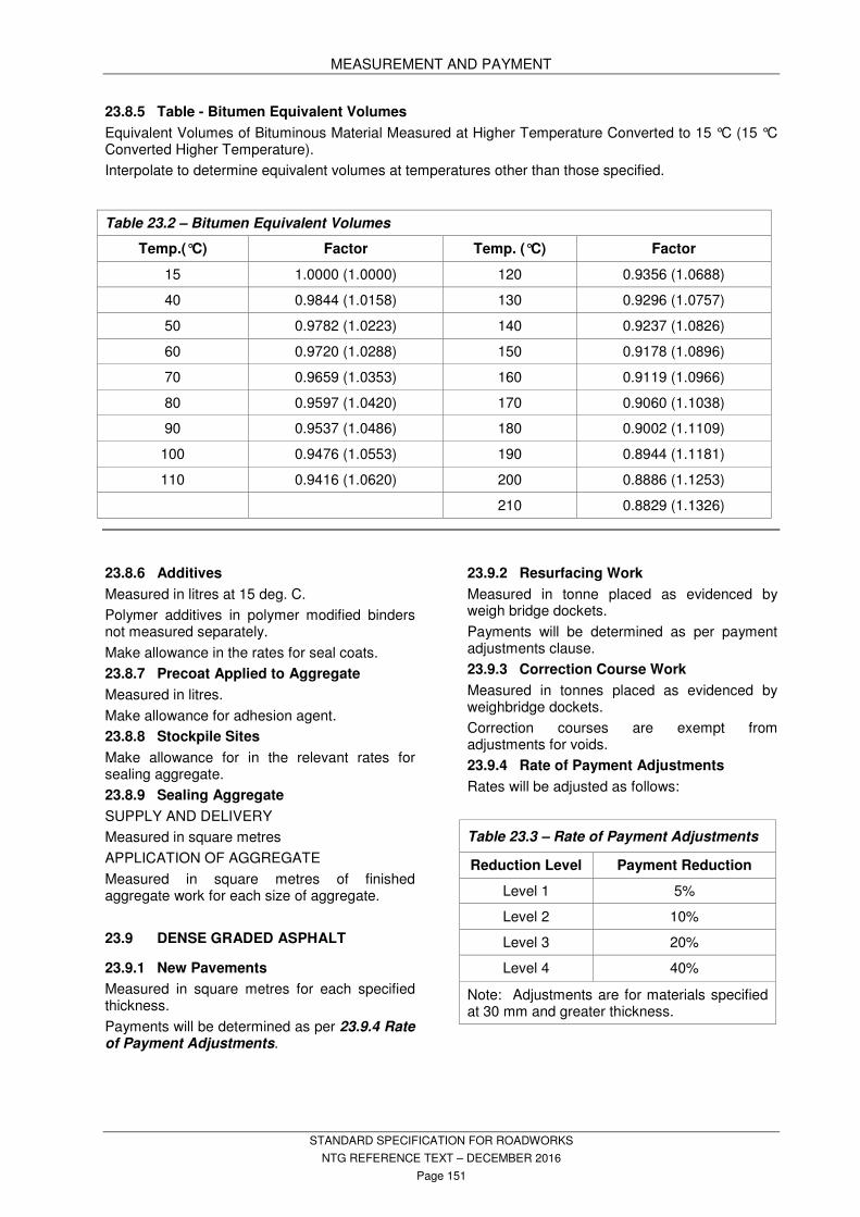
MEASUREMENT AND PAYMENT
STANDARD SPECIFICATION FOR ROADWORKS
NTG REFERENCE TEXT – DECEMBER 2016
Page 151
23.8.5 Table - Bitumen Equivalent Volumes
Equivalent Volumes of Bituminous Material Measured at Higher Temperature Converted to 15 °C (15 °C Converted Higher Temperature).
Interpolate to determine equivalent volumes at temperatures other than those specified.
23.8.6 Additives
Measured in litres at 15 deg. C.
Polymer additives in polymer modified binders not measured separately.
Make allowance in the rates for seal coats.
23.8.7 Precoat Applied to Aggregate
Measured in litres.
Make allowance for adhesion agent.
23.8.8 Stockpile Sites
Make allowance for in the relevant rates for sealing aggregate.
23.8.9 Sealing Aggregate
SUPPLY AND DELIVERY
Measured in square metres
APPLICATION OF AGGREGATE
Measured in square metres of finished aggregate work for each size of aggregate.
23.9 DENSE GRADED ASPHALT
23.9.1 New Pavements
Measured in square metres for each specified thickness.
Payments will be determined as per 23.9.4 Rate of Payment Adjustments.
23.9.2 Resurfacing Work
Measured in tonne placed as evidenced by weigh bridge dockets.
Payments will be determined as per payment adjustments clause.
23.9.3 Correction Course Work
Measured in tonnes placed as evidenced by weighbridge dockets.
Correction courses are exempt from adjustments for voids.
23.9.4 Rate of Payment Adjustments
Rates will be adjusted as follows:
Table 23.3 – Rate of Payment Adjustments
Reduction Level Payment Reduction
Level 1 5%
Level 2 10%
Level 3 20%
Level 4 40%
Note: Adjustments are for materials specified at 30 mm and greater thickness.
Table 23.2 – Bitumen Equivalent Volumes
Temp.(°C) Factor Temp. (°C) Factor
15 1.0000 (1.0000) 120 0.9356 (1.0688)
40 0.9844 (1.0158) 130 0.9296 (1.0757)
50 0.9782 (1.0223) 140 0.9237 (1.0826)
60 0.9720 (1.0288) 150 0.9178 (1.0896)
70 0.9659 (1.0353) 160 0.9119 (1.0966)
80 0.9597 (1.0420) 170 0.9060 (1.1038)
90 0.9537 (1.0486) 180 0.9002 (1.1109)
100 0.9476 (1.0553) 190 0.8944 (1.1181)
110 0.9416 (1.0620) 200 0.8886 (1.1253)
210 0.8829 (1.1326)

MEASUREMENT AND PAYMENT
STANDARD SPECIFICATION FOR ROADWORKS
NTG REFERENCE TEXT – DECEMBER 2016
Page 152
Table 23.4 - Bitumen Conformance - Class 320 Bitumen
Viscosity (at 60 °C Pa.s) of AS 2008 Class 320 Bitumen Component of the Binder
Payment Reduction (red’n)
Under 260 (Pa.s) 5% red’n for each 10 Pa.s (or part thereof) less than 260
260 – 380 (Pa.s) Nil.
Over 380 (Pa.s) 5% red’n for each 10 Pa.s (or part thereof) over 380.
Table 23.5 - Bitumen Conformance - Polymer Modified Binder (A15E)
Polymer Modified Binders A15E Payment Reduction*
Consistency (60oC Pas) 4500 - 4999 5% reduction to m2 rate ($) of lot
Consistency (60oC Pas) 4000 - 4449 10% Reduction to m2 rate ($) of lot
Consistency (60oC Pas) 4000 - 3000 20% Reduction to m2 rate ($) of lot
Consistency (60oC Pas) less than - 3000 Remove and Replace
Torsional Recovery (25oC,30s,%)1% – 5% less than specified 5% reduction to m2 rate ($) of lot
Torsional Recovery (25oC,30s,%) 6% – 10% less than specified 10% reduction to m2 rate ($) of lot
Torsional Recovery (25oC,30s,%) over 10% less than specified 20% reduction to m2 rate ($) of lot
Softening Point 0 – 5 oC less than specified 5% Reduction to m2 rate ($) of lot
Softening Point 5.1 – 10 oC less than specified 10% Reduction to m2 rate ($) of lot
Softening Point 10.1 – 15 oC less than specified 20% Reduction to m2 rate ($) of lot
Softening Point more than 15.1 – 20.0 oC less than specified 30% Reduction to m2 rate ($) of lot
Softening Point more than 20.1 oC less than specified Remove and Replace
* Payment reduction shall only apply to the test property providing highest level of non conformance
23.9.5 Rideability
Table 23.6 – Payment adjustments related to IRI over specified IRI (per lot)
Increase in specified max
IRI (per lot)
%Adjustment to the m2 rate of the lot
0.01 – 0.10 2%
0.11 – 0.20 4%
0.21 – 0.30 6%
0.31 – 0.40 8%
0.41 – 0.50 10%
0.51 – 0.60 12%
0.61 – 0.70 14%
0.71 – 0.80 16%
>0.80 Remove & Replace/Rectify
23.9.6 Progress Claims
Contractor may claim up to three-quarters of the contract rate when works are physically completed on site with balance of payment following conformance test results.
23.9.7 Payment Adjustment Applied to Sub-Contractors
Where:
(a) a payment adjustment is applied against the Contractor under the Contract; and
(b) the Contractor then applies that adjustment to the sub-contractor that carried out the Works the subject of the payment adjustment,
The Contractor will provide the sub-contractor with a copy of the document/s from the Principal as evidence that the payment adjustment applied to the Contractor.
MEASUREMENT AND PAYMENT
STANDARD SPECIFICATION FOR ROADWORKS
NTG REFERENCE TEXT – DECEMBER 2016
Page 153
23.10 SLURRY SURFACING
Payment will be made at the tendered rates for the actual quantity of accepted slurry surfacing mix spread.
Measurement;
- Slurry surfacing laid per m2 @ average
9 mm thickness, including surface preparation and supply and laying of slurry surfacing mix.
- Slurry correction volume per m2.
23.11 MISCELLANEOUS CONCRETE
Make allowance for excavation, bedding and backfilling in the following items.
23.11.1 Footpaths
Measured in linear metres for each type.
23.11.2 Vehicle Crossings and Access Strips
Measured in square metres for each type.
Make allowance for reinforcement.
23.11.3 Kerbs and Gutters
Measured in linear metres for each type (any drainage structures/crossings excluded from measured lengths.)
23.11.4 Inverts
Measured in linear metres.
23.11.5 Wheelchair Crossings
Measured by number.
23.11.6 Traffic Island and Median Infill
Measured in square metres.
23.12 DRAINAGE WORKS
23.12.1 Excavation in Trenching
Measured in in-situ cubic metres for the specified range of depths to invert.
The length of the trench shall be measured between the outside face of headwalls or between the centre of pits.
The width of the trench shall be the outside width of the culvert plus 300 mm on each side.
The depth of the trench is the average of the depths to invert measured at the structure at each end of the section.
The depth to invert is the lesser of the depth below natural surface and the depth below finished surface level. In the case of kerbside structures, the finished surface level is measured at the top of kerb.
Make allowance for shoring, bedding, inlet and outlet structures and irregularities in the natural surface where applicable.
23.12.2 Supply, Load, Transport, Bed, Lay and Backfill Culverts
Measured in linear metres along the invert of the culvert as the distance between the outside face of headwalls or other structures for the type and size scheduled.
Multiple barrel culverts are measured as the single distance between the outside face of headwalls or other structures.
Excavation is measured separately.
23.12.3 Excavate, Supply, Load, Transport, Bed, Lay and Backfill Culverts
Measured in linear metres along the invert of the culvert between the outside face of headwalls/inside face of pits or other structures for the type and size scheduled.
Multiple barrel culverts are measured as the single distance between the outside face of headwalls or other structures.
Make allowance for RC floor slabs for precast box culverts.
23.12.4 Concrete Headwalls, Maintenance Holes and Other Structures
Measured in cubic metres.
Measured by number.
23.12.5 Collar Joints, Bandage Joints, Anchor Blocks and End Caps
Measured by number.
Make allowance for splay ends.
23.12.6 Inlet and Outlet Channels
Measured in in-situ cubic metres.
Not measured separately for culvert waterways less than 2 square metres in cross-sectional area and channels less than 50 metres long.
23.12.7 Open Unlined Drains
Measured in in situ cubic metres.
23.12.8 Subsoil Drains
Measured in linear metres.
Make allowance for blocks, headwalls, filter material, geotextiles, and connection to existing drainage system.
23.12.9 Demolish and Remove Existing Drainage Structures
Measured as an item.
Make allowance for backfilling.
23.13 PROTECTION WORKS
23.13.1 Geotextile Fabric
Measured in square metres of completed area.
Make allowance for supply and placement.
Make allowance for laps and folds.
23.13.2 Stone Pitching
Measured in square metres of the face area.

MEASUREMENT AND PAYMENT
STANDARD SPECIFICATION FOR ROADWORKS
NTG REFERENCE TEXT – DECEMBER 2016
Page 154
23.13.3 Grouted Stone Pitching
Measured in square metres of the face area.
Make allowance for weep holes.
23.13.4 Dumped Rock Protection
Measured in cubic metres.
23.13.5 Rubble
Measured in cubic metres.
23.13.6 Gabions
Measured in cubic metres.
Includes the excavation, steel wire mesh box and the stone filling.
23.13.7 Reno Mattresses
Measured in square metres.
Includes the excavation, steel wire mesh box and the stone filling.
23.13.8 Revetment Mattresses
Measured in square metres.
23.13.9 Embankment Protection - Concrete
Measured in square metres of the face area.
Make allowance for weep holes.
23.13.10 Margins
Measured in linear metres.
Make allowance for reinforcement.
23.14 ROAD FURNITURE AND TRAFFIC CONTROL DEVICES
23.14.1 Fencing
Measured in linear metres.
Make allowance for gates which are not measured separately.
Make allowance for clearing of fence lines which is not measured separately.
23.14.2 Guide Posts
Measured by number.
Make allowance for delineators.
23.14.3 Road Signs, Supply and Install
Measured by number of each sign type or classification.
23.14.4 Reinstate/Relocate Existing Road Signs
Measured by number.
23.14.5 Flood Gauge Posts
Measured by number.
Make allowance for gauge.
23.14.6 Cattle Grids
Size 10 m or 12.4 m, with or without concrete approach.
Measured by number.
Make allowance for gate in adjacent fence.
23.14.7 Steel Beam Guardrail
Measured from centre to centre of end posts in linear metres.
Make allowance for terminals, delineators and fittings.
23.15 PAVEMENT MARKING
23.15.1 Pavement Marking – New Work
The following are measured in linear metres for type of painted line, inclusive of unpainted gaps:
- Continuity line - (single broken).
- Unbroken lane line - (single continuous).
- Broken lane line or separation line - (single).
- Barrier lines both directions - (double continuous longitudinal lines).
- Barrier lines one direction - (double longitudinal lines broken on one side, continuous on the other).
- Edge line - (single continuous).
- No Standing Any Time - (yellow single continuous).
All other markings measured as an item.
Make allowance for the specified spherical glass beads with all markings.
Removal of existing pavement markings measured as an item.
23.15.2 Pavement Marking – Resealing Contracts
The Superintendent will pay for all pavement marking work directly to the Panel Contractor selected to perform the pavement marking work under this contract.
Measurement of completed pavement marking will be done jointly with the reseal contractor, the panel contract linemarker and the Superintendent.
Recording of localities and extent of pavement marking work, including set out prior to line marking activities are measured as an item.
Include all activities required to co-ordinate the pavement marking work.
23.15.3 Raised Retroreflective Pavement Markers
Measured by number for each type.
23.16 LANDSCAPE
23.16.1 Site Preparation
Measured as an item.
Make allowance for any filling and levelling required.
23.16.2 Topsoil
Measured in square metres.
Make allowance for any supply required, and spreading.

MEASUREMENT AND PAYMENT
STANDARD SPECIFICATION FOR ROADWORKS
NTG REFERENCE TEXT – DECEMBER 2016
Page 155
23.16.3 Trees, Shrubs and Ground Covers
Measured by number of each type of genus and species.
Make allowance for supply of plants, mulch, fertilisers, excavation of planting holes, and planting.
23.16.4 Irrigation
Measured as an item.
Make allowance for any design requirements, cost of approvals and connection to the water supply, cost of testing, and provision of as constructed drawings.
23.16.5 Grassing
Measured in square metres.
Make allowance for reseeding.
23.16.6 Watering
Measured as an item.
Note that cost of water will be borne by the Superintendent.
23.17 DUCTING AND CONDUITS
23.17.1 Electrical Ducting
Measured in linear metres.
Make allowance for excavation and backfilling trenches, marker tapes, draw wires and kerb markers.
23.17.2 Water Ducting
Measured in linear metres.
Make allowance for excavation and backfilling trenches, marker tapes, draw wires and kerb markers.
23.17.3 Conduit Markers
Measured by number.
23.18 TRAFFIC CONTROL SIGNALS
23.18.1 Supply and Install Pedestals and Footings
Measured by number.
23.18.2 Supply and Install Highmast Pedestals and Footings
Measured by number.
23.18.3 Supply and Install Non-standard Pedestals and Footings
Measured by number.
23.18.4 Supply and Install Vehicle and Pedestrian Signal Lanterns
Measured by number.
Make allowance for terminal assembly, target boards, cowls and louvres, and all ancillary items.
23.18.5 Install and Commission Controller
Measured as an item.
Make allowance for all ancillary items such as surge reduction filter and earth stake.
23.18.6 Supply, Install and Test Multicore Connecting Cable
Measured in linear metres.
23.18.7 Supply, Install and Test Detector Loop Feeder Cables
Measured in linear metres.
23.18.8 Supply and Install Detector Loops
Measured by number.
23.18.9 Provision of Power Connection
Measured as an item.
23.18.10 Supply and Install Conduits
Measured in linear metres.
Make allowance for draw wires, end caps, and ancillary items.
23.18.11 Supply and Install Conduit Junction Pits
Measured by number.
23.18.12 Supply and Install Detector Pits
Measured by number.
23.18.13 Supply and Install Pedestrian Push Button and Audio-tactile Assemblies
Measured by number.
23.18.14 Supply and Install Communications Isolation Pillar
Measured as an item.
23.18.15 Documents and Plans
Measured as an item.
23.18.16 Provision of Communications Line
Measured by number.
23.19 TRAFFIC COUNTING STATIONS
23.19.1 Install Cabinet
Measured as an item.
Make allowance for supply and installation of terminal blocks and switchboard.
Make allowance for drawing of labelled loop layout and terminal blocks.
23.19.2 Construction of Pole Foundation
Measured as an item.
Make allowance for excavation, reinforcement and rag bolts.
23.19.3 Supply and Install Vehicle Loop Detectors
Measured by number.
Make allowance for cutting, install cable, junction boxes and detector feeder cables.

MEASUREMENT AND PAYMENT
STANDARD SPECIFICATION FOR ROADWORKS
NTG REFERENCE TEXT – DECEMBER 2016
Page 156
23.19.4 Install Piezo Axle Sensors
Measured by number.
Make allowance for supply and installation of feeder cables.
23.19.5 Install Pole Assembly
Measured as an item.
Make allowance for installation of solar power supply.
23.19.6 Supply and Install Conduits
Measured by length.
Make allowance for excavation, ducting, reinstatement and connections.
23.20 STREET LIGHTING
23.20.1 Install Light Columns
Measured by number.
Make allowance for installation of street lighting columns including the following:
- trenching and installation of cables including marker tape and backfilling;
- supply and installation of footings and hold down bolts;
- installation of distribution pillars;
- connections; and
- testing and commissioning.
23.20.2 Supply and Install Conduits
Measured in metres.
Make allowance for draw wires, end caps and ancillary items.
Cable installation is paid for in the “Install Light Columns” item.
23.20.3 Removal of Existing Street Lighting
Measured by number.
Make allowance for removal of existing footings and the delivery of the salvaged materials to the specified location.
23.20.4 Provision of Temporary Lighting
Measured as an item.
Make allowance for temporary lighting and additional work required by PowerWater.
23.20.5 Connection of Power
Measured as an item.
Make allowance for fees and charges and additional work required by PowerWater.
23.21 DIRECTIONAL (THRUST) BORING
23.21.1 Directional Boring With Pipe Casing
Measured in linear metres.
Includes supply of pipe casing and filling of cavities.
23.21.2 Directional Boring Without Pipe Casing
Measured in linear metres.
Includes filling of cavities
23.22 OTHER REQUIREMENTS
Refer to PROJECT SPECIFIC REQUIREMENTS in the RFT.
.

REFERENCED DOCUMENTS
STANDARD SPECIFICATION FOR ROADWORKS
NTG REFERENCE TEXT – DECEMBER 2016
Page 157
24 REFERENCED AUSTRALIAN STANDARDS
Referenced Australian Standards
Use Standards, and their amendments, current 3 months before the date for the close of tenders except where different editions and/or amendments are required by statutory authorities, including, but not limited to, NATA and the National Construction Code including the Building Code of Australia.
Dates entered like this (R2013) indicate that a Standard was reviewed and re-issued unaltered in the year cited in the parentheses.
Entries in Times New Roman italics indicate Standards not cited in this document but which may be useful references.
AS 1012 (set) - Methods of testing concrete
AS 1012.3.1 2014 - Determination of properties related to the consistency of concrete -
Slump Test
AS 1012.8.1 2014 - Method for making and curing concrete - Compression and indirect
tensile test specimens
AS 1012.9 2014 - Compressive strength tests - Concrete, grout and mortar
specimens
AS 1074 1989 Steel tubes and tubulars for ordinary services
AS 1100 (set) - Technical drawing
AS 1111 (set) 2015 ISO metric hexagon commercial bolts and screws - Product Grade C
AS 1112 (set) 2015 ISO metric hexagon nuts
AS 1141 (set) - Methods for sampling and testing aggregates
AS 1141.0 1999 - List of Methods
AS 1141.1 2015 - Definitions
AS 1141.2 2015 - Basic testing equipment
AS 1141.3.1 2012 - Sampling - Aggregates
AS 1141.11.1 2009 - Particle size distribution – Sieving method (Includes Amdt 1:2011,
Amdt 2:2016)
AS 1141.14 2007 - Particle shape, by proportional caliper
AS 1141.15 1999 - Flakiness index
AS 1141.18 1996 - Crushed particles in coarse aggregate derived from gravel
AS 1141.20.1 2000 (R2013)
- Average least dimension - Direct measurement (nominal size 10 mm and greater)
AS 1141.20.2 2000 (R2013)
- Average least dimension – Direct measurement (nominal size 7 mm and 5mm)
AS 1141.20.3 2000 (R2013)
- Average least dimension – Calculation (nomograph).
AS 1141.23 2009 - Los Angeles value
AS 1141.24 2013 - Aggregate soundness – Evaluation by exposure to sodium
sulphate solution
AS 1141.25.1 2003 (R2013)
- Degradation factor – Source rock
AS 1141.26 2008 - Secondary minerals content in igneous rocks
AS 1141.29 2014 - Accelerated soundness index by reflux
AS 1141.40 1999 - Polished aggregate friction value - Vertical road-wheel machine
AS 1141.41 1999 - Polished aggregate friction value – Horizontal bed machine
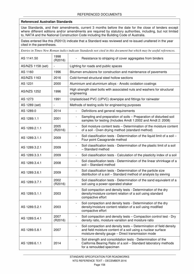
REFERENCED DOCUMENTS
STANDARD SPECIFICATION FOR ROADWORKS
NTG REFERENCE TEXT – DECEMBER 2016
Page 158
Referenced Australian Standards
Use Standards, and their amendments, current 3 months before the date for the close of tenders except where different editions and/or amendments are required by statutory authorities, including, but not limited to, NATA and the National Construction Code including the Building Code of Australia.
Dates entered like this (R2013) indicate that a Standard was reviewed and re-issued unaltered in the year cited in the parentheses.
Entries in Times New Roman italics indicate Standards not cited in this document but which may be useful references.
AS 1141.50 1998 (R2016)
- Resistance to stripping of cover aggregates from binders
AS/NZS 1158 (set) - Lighting for roads and public spaces
AS 1160 1996 Bitumen emulsions for construction and maintenance of pavements
AS/NZS 1163 2016 Cold-formed structural steel hollow sections
AS 1231 2000 Aluminium and aluminium alloys - Anodic oxidation coatings
AS/NZS 1252 1996 High strength steel bolts with associated nuts and washers for structural engineering
AS 1273 1991 Unplasticised PVC (UPVC) downpipe and fittings for rainwater
AS 1289 (set) - Methods of testing soils for engineering purposes
AS 1289.0 2014 - Definitions and general requirements
AS 1289.1.1 2001 - Sampling and preparation of soils – Preparation of disturbed soil
samples for testing (Includes Amdt 1:2002 and Amdt 2: 2008)
AS 1289.2.1.1 2005 (R2016)
- Soil moisture content tests – Determination of the moisture content of a soil - Oven drying method (standard method)
AS 1289.3.1.1 2009 - Soil classification tests - Determination of the liquid limit of a soil –
Four point Casagrande method
AS 1289.3.2.1 2009 - Soil classification tests - Determination of the plastic limit of a soil
– Standard method
AS 1289.3.3.1 2009 - Soil classification tests - Calculation of the plasticity index of a soil
AS 1289.3.4.1 2008 - Soil classification tests - Determination of the linear shrinkage of a
soil – Standard method
AS 1289.3.6.1 2009 - Soil classification tests - Determination of the particle size
distribution of a soil – Standard method of analysis by sieving
AS 1289.3.7.1 2002 (R2016)
- Soil classification tests - Determination of the sand equivalent of a soil using a power-operated shaker
AS 1289.5.1.1 2003 - Soil compaction and density tests - Determination of the dry
density/moisture content relation of a soil using standard compactive effort
AS 1289.5.2.1 2003 - Soil compaction and density tests - Determination of the dry
density/moisture content relation of a soil using modified compactive effort
AS 1289.5.4.1 2007 (R2016)
- Soil compaction and density tests – Compaction control test - Dry density ratio, moisture variation and moisture ratio
AS 1289.5.8.1 2007 - Soil compaction and density tests – Determination of field density
and field moisture content of a soil using a nuclear surface moisture-density gauge – Direct transmission mode
AS 1289.6.1.1 2014 - Soil strength and consolidation tests - Determination of the
California Bearing Ratio of a soil – Standard laboratory methods for a remoulded specimen

REFERENCED DOCUMENTS
STANDARD SPECIFICATION FOR ROADWORKS
NTG REFERENCE TEXT – DECEMBER 2016
Page 159
Referenced Australian Standards
Use Standards, and their amendments, current 3 months before the date for the close of tenders except where different editions and/or amendments are required by statutory authorities, including, but not limited to, NATA and the National Construction Code including the Building Code of Australia.
Dates entered like this (R2013) indicate that a Standard was reviewed and re-issued unaltered in the year cited in the parentheses.
Entries in Times New Roman italics indicate Standards not cited in this document but which may be useful references.
AS 1289.7.1.1 2003 Methods of testing soils for engineering purposes - Soil reactivity tests -
Determination of the shrinkage index of a soil
AS 1289.7.1.2 1998
(R2013)
Methods of testing soils for engineering purposes - Soil reactivity tests -
Determination of the shrinkage index of a soil - Loaded shrinkage index
AS 1289.7.1.3 1998
(R2013)
Methods of testing soils for engineering purposes - Soil reactivity tests -
Determination of the shrinkage index of a soil - Core shrinkage index
AS 1345 1995 Identification of the contents of pipes, conduits and ducts
AS 1348 2002 Road and traffic engineering - Glossary of terms (available withdrawn)
AS 1379 2007 Specification and supply of concrete (Includes Amdt 1: 2009, Amdt 2: 2015 & Supp 1: 2009)
AS 1397 2011 Continuous hot-dip metallic coated steel sheet and strip - Coatings of zinc and zinc alloyed with aluminium and magnesium (Includes Amdt 1:2012)
AS/NZS 1477 2006 PVC pipes and fittings for pressure applications (Includes Amdt 1:2009)
AS 1478.1 2000 Chemical admixtures for concrete, mortar and grout – Admixtures for concrete
AS/NZS 1554 (set) - Structural steel welding
AS 1579 2001 Arc-welded steel pipes and fittings for water and waste-water
AS 1580 (set) - Paints and related materials – Methods of test
AS/NZS 1580.108.1 1994 - Determination of dry film thickness on metallic substrates – Non-
destructive methods
AS/NZS 1580.205.4 1998 (R2013)
- Application properties – Airless spraying
AS/NZS 1594 2002 Hot rolled steel flat products
AS 1597 (set) - Precast reinforced concrete box culverts
AS 1597.1 2010 - Small culverts (not exceeding 1200 mm span and 1200 mm
height)
AS 1597.2 2013 - Large culverts (exceeding 1200 mm span or 1200 mm height and
up to and including 4200 mm span and 4200 mm height)
AS 1604.1 2012 Specification for preservative treatment – Sawn and round timber
AS 1627 (set) - Metal finishing - Preparation and pretreatment of surfaces
AS 1627.1 2003 - removal of oil, grease and related contamination
AS 1627.2 2002 - Power tool cleaning
AS 1627.4 2005 - Abrasive blast cleaning of steel
AS 1627.9 2002 - Pictorial surface preparation standards for painting steel surfaces
AS 1672.1 1997 (R2016)
Limes and limestones – Limes for building
AS 1678 (set) - Emergency procedure guide – Transport
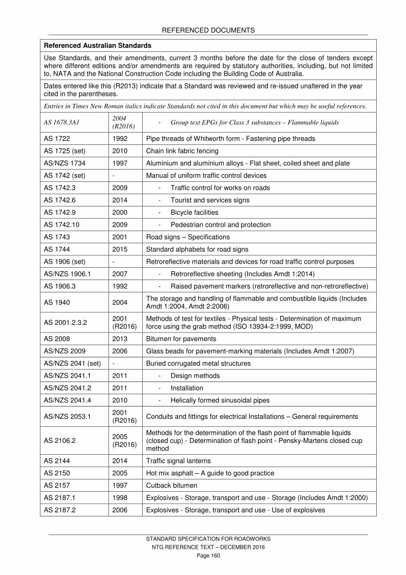
REFERENCED DOCUMENTS
STANDARD SPECIFICATION FOR ROADWORKS
NTG REFERENCE TEXT – DECEMBER 2016
Page 160
Referenced Australian Standards
Use Standards, and their amendments, current 3 months before the date for the close of tenders except where different editions and/or amendments are required by statutory authorities, including, but not limited to, NATA and the National Construction Code including the Building Code of Australia.
Dates entered like this (R2013) indicate that a Standard was reviewed and re-issued unaltered in the year cited in the parentheses.
Entries in Times New Roman italics indicate Standards not cited in this document but which may be useful references.
AS 1678.3A1 2004
(R2016) - Group text EPGs for Class 3 substances – Flammable liquids
AS 1722 1992 Pipe threads of Whitworth form - Fastening pipe threads
AS 1725 (set) 2010 Chain link fabric fencing
AS/NZS 1734 1997 Aluminium and aluminium alloys - Flat sheet, coiled sheet and plate
AS 1742 (set) - Manual of uniform traffic control devices
AS 1742.3 2009 - Traffic control for works on roads
AS 1742.6 2014 - Tourist and services signs
AS 1742.9 2000 - Bicycle facilities
AS 1742.10 2009 - Pedestrian control and protection
AS 1743 2001 Road signs – Specifications
AS 1744 2015 Standard alphabets for road signs
AS 1906 (set) - Retroreflective materials and devices for road traffic control purposes
AS/NZS 1906.1 2007 - Retroreflective sheeting (Includes Amdt 1:2014)
AS 1906.3 1992 - Raised pavement markers (retroreflective and non-retroreflective)
AS 1940 2004 The storage and handling of flammable and combustible liquids (Includes Amdt 1:2004, Amdt 2:2006)
AS 2001.2.3.2 2001 (R2016)
Methods of test for textiles - Physical tests - Determination of maximum force using the grab method (ISO 13934-2:1999, MOD)
AS 2008 2013 Bitumen for pavements
AS/NZS 2009 2006 Glass beads for pavement-marking materials (Includes Amdt 1:2007)
AS/NZS 2041 (set) - Buried corrugated metal structures
AS/NZS 2041.1 2011 - Design methods
AS/NZS 2041.2 2011 - Installation
AS/NZS 2041.4 2010 - Helically formed sinusoidal pipes
AS/NZS 2053.1 2001 (R2016)
Conduits and fittings for electrical Installations – General requirements
AS 2106.2 2005 (R2016)
Methods for the determination of the flash point of flammable liquids (closed cup) - Determination of flash point - Pensky-Martens closed cup method
AS 2144 2014 Traffic signal lanterns
AS 2150 2005 Hot mix asphalt – A guide to good practice
AS 2157 1997 Cutback bitumen
AS 2187.1 1998 Explosives - Storage, transport and use - Storage (Includes Amdt 1:2000)
AS 2187.2 2006 Explosives - Storage, transport and use - Use of explosives
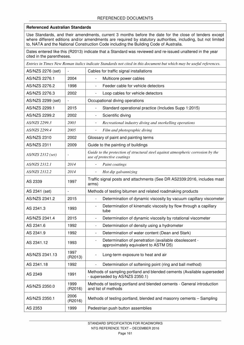
REFERENCED DOCUMENTS
STANDARD SPECIFICATION FOR ROADWORKS
NTG REFERENCE TEXT – DECEMBER 2016
Page 161
Referenced Australian Standards
Use Standards, and their amendments, current 3 months before the date for the close of tenders except where different editions and/or amendments are required by statutory authorities, including, but not limited to, NATA and the National Construction Code including the Building Code of Australia.
Dates entered like this (R2013) indicate that a Standard was reviewed and re-issued unaltered in the year cited in the parentheses.
Entries in Times New Roman italics indicate Standards not cited in this document but which may be useful references.
AS/NZS 2276 (set) - Cables for traffic signal installations
AS/NZS 2276.1 2004 - Multicore power cables
AS/NZS 2276.2 1998 - Feeder cable for vehicle detectors
AS/NZS 2276.3 2002 - Loop cables for vehicle detectors
AS/NZS 2299 (set) - Occupational diving operations
AS/NZS 2299.1 2015 - Standard operational practice (Includes Supp 1:2015)
AS/NZS 2299.2 2002 - Scientific diving
AS/NZS 2299.3 2003 - Recreational industry diving and snorkelling operations
AS/NZS 2299.4 2005 - Film and photographic diving
AS/NZS 2310 2002 Glossary of paint and painting terms
AS/NZS 2311 2009 Guide to the painting of buildings
AS/NZS 2312 (set) - Guide to the protection of structural steel against atmospheric corrosion by the
use of protective coatings
AS/NZS 2312.1 2014 - Paint coatings
AS/NZS 2312.2 2014 - Hot dip galvannizing
AS 2339 1997 Traffic signal posts and attachments (See DR AS2339:2016, includes mast arms)
AS 2341 (set) - Methods of testing bitumen and related roadmaking products
AS/NZS 2341.2 2015 - Determination of dynamic viscosity by vacuum capillary viscometer
AS 2341.3 1993 - Determination of kinematic viscosity by flow through a capillary
tube
AS/NZS 2341.4 2015 - Determination of dynamic viscosity by rotational viscometer
AS 2341.6 1992 - Determination of density using a hydrometer
AS 2341.9 1992 - Determination of water content (Dean and Stark)
AS 2341.12 1993 - Determination of penetration (available obsolescent -
approximately equivalent to ASTM D5)
AS/NZS 2341.13 1997 (R2013)
- Long-term exposure to heat and air
AS 2341.18 1992 - Determination of softening point (ring and ball method)
AS 2349 1991 Methods of sampling portland and blended cements (Available superseded - superseded by AS/NZS 2350.1)
AS/NZS 2350.0 1999 (R2016)
Methods of testing portland and blended cements - General introduction and list of methods
AS/NZS 2350.1 2006 (R2016)
Methods of testing portland, blended and masonry cements – Sampling
AS 2353 1999 Pedestrian push button assemblies

REFERENCED DOCUMENTS
STANDARD SPECIFICATION FOR ROADWORKS
NTG REFERENCE TEXT – DECEMBER 2016
Page 162
Referenced Australian Standards
Use Standards, and their amendments, current 3 months before the date for the close of tenders except where different editions and/or amendments are required by statutory authorities, including, but not limited to, NATA and the National Construction Code including the Building Code of Australia.
Dates entered like this (R2013) indicate that a Standard was reviewed and re-issued unaltered in the year cited in the parentheses.
Entries in Times New Roman italics indicate Standards not cited in this document but which may be useful references.
AS 2423 2002 Coated steel wire fencing products for terrestrial, aquatic and general use
AS/NZS 2433 1994 Plastics - Method for exposure to ultraviolet lamps
AS 2439.1 2007 Perforated plastics drainage and effluent pipe and fittings - Perforated drainage pipe and associated fittings
AS 2698 (set) - Plastics pipes and fittings for irrigation and rural applications
AS 2698.2 2000 - Polyethylene rural pipe
AS 2698.3 1990 - Mechanical joint fittings for use with polyethylene micro-irrigation
pipes
AS 2700 (set) 2011 Colour Standards for general purposes
AS 2703 2008 Vehicle loop detector sensors
AS 2758 (set) Aggregates and rock for engineering purposes
AS 2758.1 2014 - Concrete aggregates
AS 2758.2 2009 - Aggregate for sprayed bituminous surfacing
AS 2758.5 2009 - Coarse asphalt aggregates
AS 2809.5 2001 Road tank vehicles for dangerous goods - Tankers for bitumen based products
AS 2815 (set) - Training and certification of occupational divers
AS 2815.1 2008 - Occupational SCUBA diver - Standard
AS/NZS 2815.2 2013 - Surface supplied diving to 30 m
AS 2815.3 1992 - Air diving to 50 m
AS 2815.4 1992 - Bell diving
AS/NZS 2815.5 2013 - Dive supervisor
AS 2865 2009 Confined Spaces
AS 2870 2011 Residential slabs and footings
AS 2876 2000 Concrete kerbs and channels (gutters) - Manually or machine placed (Available withdrawn)
AS 2891 (set) - Methods of sampling and testing asphalt
AS/NZS 2891.1.1 2013 - Sampling – Loose asphalt
AS 2891.1.2 2008 - Sampling – Coring method
AS 2891.1.3 2008 - Sampling – Asphalt from slabs
AS/NZS 2891.3.1 2013 - Binder content and aggregate grading – Reflux method
AS/NZS 2891.3.2 2013 - Binder content and aggregate grading – Centrifugal extraction
method
AS/NZS 2891.3.3 2013 - Binder content and aggregate grading – Pressure filter method

REFERENCED DOCUMENTS
STANDARD SPECIFICATION FOR ROADWORKS
NTG REFERENCE TEXT – DECEMBER 2016
Page 163
Referenced Australian Standards
Use Standards, and their amendments, current 3 months before the date for the close of tenders except where different editions and/or amendments are required by statutory authorities, including, but not limited to, NATA and the National Construction Code including the Building Code of Australia.
Dates entered like this (R2013) indicate that a Standard was reviewed and re-issued unaltered in the year cited in the parentheses.
Entries in Times New Roman italics indicate Standards not cited in this document but which may be useful references.
AS/NZS 2891.5 2015 - Compaction of asphalt by Marshall method and determination of
stability and flow – Marshall procedure
AS/NZS 2891.7.1 2015 - Determination of maximum density of asphalt – Water
displacement method
AS/NZS 2891.7.3 2014 - Determination of maximum density of asphalt – Methylated spirits
displacement
AS/NZS 2891.8 2014 - Voids and volumetric properties of compacted asphalt mixes
AS/NZS 2891.9.1 2014 - Determination of bulk density of compacted asphalt – Waxing
procedure
AS/NZS 2891.9.2 2014 - Determination of bulk density of compacted asphalt –
Presaturation method
AS/NZS 2891.9.3 2014 - Determination of bulk density of compacted asphalt – Mensuration
method
AS 2979 1998 Traffic signal mast arms
AS/NZS 3000 2007 Electrical installations (known as the Australian/New Zealand Wiring Rules) (Includes Amdt 1:2009 and Amdt 2:2012)
AS/NZS 3100 2009 Approval and test specification - General requirements for electrical equipment (Includes Amdt 1:2010, Amdt 2:2012, Amdt 3:2014, Amdt 4:2015)
AS/NZS 3191 2008 Electric flexible cords
AS/NZS 3500 (set) - Plumbing and drainage
AS/NZS 3500.1 2015 - Water services
AS 3568 1999 Oils for reducing the viscosity of residual bitumen for pavements
AS 3600 2009 Concrete structures (Includes Amdt 1:2010, Amdt 2:2013, Supp 1:2014)
AS 3610.1 2010 Formwork for concrete – Documentation and surface finish
AS/NZS 3661.1 1993 Slip resistance of pedestrian surfaces - Requirements (Available superseded.
Superseded by AS/NZS 4586:1999 and AS/NZS 4663 2002)
AS/NZS 3661.2 1994 Slip resistance of pedestrian surfaces – Guide to the reduction of slip hazards
AS/NZS 3678 2016 Structural steel - Hot rolled plates, floorplates and slabs
AS/NZS 3679.1 2016 Structural steel - Hot rolled bars and sections
AS 3706 (set) - Geotextiles – Methods of test
AS 3706.1 2012 - General requirements, sampling, conditioning, basic physical
properties and statistical analysis
AS 3706.2 2012 - Determination of tensile properties – Wide strip and grab method
AS 3706.3 2012 - Determination of tearing strength – Trapezoidal method
AS 3706.4 2012 - Determination of bursting strength – California bearing ratio (CBR)
– Plunger method
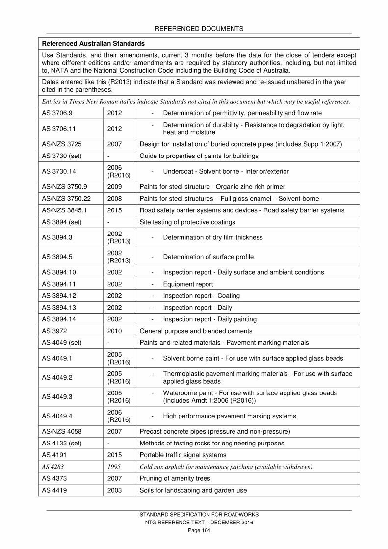
REFERENCED DOCUMENTS
STANDARD SPECIFICATION FOR ROADWORKS
NTG REFERENCE TEXT – DECEMBER 2016
Page 164
Referenced Australian Standards
Use Standards, and their amendments, current 3 months before the date for the close of tenders except where different editions and/or amendments are required by statutory authorities, including, but not limited to, NATA and the National Construction Code including the Building Code of Australia.
Dates entered like this (R2013) indicate that a Standard was reviewed and re-issued unaltered in the year cited in the parentheses.
Entries in Times New Roman italics indicate Standards not cited in this document but which may be useful references.
AS 3706.9 2012 - Determination of permittivity, permeability and flow rate
AS 3706.11 2012 - Determination of durability - Resistance to degradation by light,
heat and moisture
AS/NZS 3725 2007 Design for installation of buried concrete pipes (includes Supp 1:2007)
AS 3730 (set) - Guide to properties of paints for buildings
AS 3730.14 2006 (R2016)
- Undercoat - Solvent borne - Interior/exterior
AS/NZS 3750.9 2009 Paints for steel structure - Organic zinc-rich primer
AS/NZS 3750.22 2008 Paints for steel structures – Full gloss enamel – Solvent-borne
AS/NZS 3845.1 2015 Road safety barrier systems and devices - Road safety barrier systems
AS 3894 (set) - Site testing of protective coatings
AS 3894.3 2002 (R2013)
- Determination of dry film thickness
AS 3894.5 2002 (R2013)
- Determination of surface profile
AS 3894.10 2002 - Inspection report - Daily surface and ambient conditions
AS 3894.11 2002 - Equipment report
AS 3894.12 2002 - Inspection report - Coating
AS 3894.13 2002 - Inspection report - Daily
AS 3894.14 2002 - Inspection report - Daily painting
AS 3972 2010 General purpose and blended cements
AS 4049 (set) - Paints and related materials - Pavement marking materials
AS 4049.1 2005 (R2016)
- Solvent borne paint - For use with surface applied glass beads
AS 4049.2 2005 (R2016)
- Thermoplastic pavement marking materials - For use with surface applied glass beads
AS 4049.3 2005 (R2016)
- Waterborne paint - For use with surface applied glass beads (Includes Amdt 1:2006 (R2016))
AS 4049.4 2006 (R2016)
- High performance pavement marking systems
AS/NZS 4058 2007 Precast concrete pipes (pressure and non-pressure)
AS 4133 (set) - Methods of testing rocks for engineering purposes
AS 4191 2015 Portable traffic signal systems
AS 4283 1995 Cold mix asphalt for maintenance patching (available withdrawn)
AS 4373 2007 Pruning of amenity trees
AS 4419 2003 Soils for landscaping and garden use

REFERENCED DOCUMENTS
STANDARD SPECIFICATION FOR ROADWORKS
NTG REFERENCE TEXT – DECEMBER 2016
Page 165
Referenced Australian Standards
Use Standards, and their amendments, current 3 months before the date for the close of tenders except where different editions and/or amendments are required by statutory authorities, including, but not limited to, NATA and the National Construction Code including the Building Code of Australia.
Dates entered like this (R2013) indicate that a Standard was reviewed and re-issued unaltered in the year cited in the parentheses.
Entries in Times New Roman italics indicate Standards not cited in this document but which may be useful references.
AS 4454 2012 Composts, soil conditioners and mulches (Includes Amdt 1:2012)
AS/NZS 4586 1999 Slip resistance classification of new pedestrian surface materials
AS/NZS 4663 2002 Slip resistance measurement of existing pedestrian surfaces
AS/NZS 4671 2001 Steel reinforcing materials (Includes Amdt 1:2003)
AS/NZS 4680 2006 Hot-dip galvanized (zinc) coatings on fabricated ferrous articles
AS 4742 2003 Earth-moving machinery - Machine-mounted forward and reverse audible
warning alarm - Sound test method (withdrawn)(See ISO 9533:1989)
AS/NZS 5000.1 2005 Electric cables – Polymetric insulated – For working voltages up to and including 0.6/1 (1.2) kV (Includes Amdt 1:2006)
AS 5100.5 2004 Bridge design - Concrete (Includes Amdt 1:2010, Amdt 2:2010, Supp 1:2008)
AS/NZS ISO 9000 2016 Quality management systems - Fundamentals and vocabulary
AS/NZS ISO 31000 2009 Risk Management – Principles and guidelines
AS/NZS 61558 (set) - Safety of power transformers, power supplies, reactors and similar products for supply voltages up to 1 100 V
AS/NZS 61558.2.4 2009 - Particular requirements for isolating transformers for general use
(IEC 61558-2-4: Ed 2, SDT) (Includes Amdt 1:2012)
AS/NZS 61558.2.6 2009 - Particular requirements for safety isolating transformers for
general use (IEC 61558-2-6: Ed 2, MOD) (Includes Amdt 1:2012)
ISO 9533 2010 Earth-moving machinery - Machine-mounted audible travel alarms and forward horns - Test methods and performance criteria

REFERENCED DOCUMENTS
STANDARD SPECIFICATION FOR ROADWORKS
NTG REFERENCE TEXT – DECEMBER 2016
Page 166
25 OTHER REFERENCED AUTHORITIES AND DOCUMENTS
Other Referenced Authorities and Documents
AAPA Australian Asphalt Pavement Association
APAS Australian Paint Approval Scheme
APAS AP-S0041/3 Pavement marking materials – cold applied plastic
APAS AP-S0042 Glass beads for use in pavement marking paints
APVMA Australian Pesticides and Veterinary Medicines Authority
AGBT Austroads Guide to Bridge Technology
AGPT Austroads Guide to Pavement Technology
AGPT04B-14 - Part 4B Asphalt
AGPT04H-08 - Part 4H: Test Methods
AGPT04K-09 - Part 4K: Seals
AGPT-T Austroads Guide to Pavement Technology - Test methods
AGPT-T103-06 - Pre-treatment and Loss on Heating of Bitumen Multigrade and polymer
Binders (rolling thin film oven [RTFO] test)
AGPT-T108-06 - Segregation of Polymer Modified Binders
AGPT-T109-06 - Ease of Remixing of Polymer Modified Binders
AGPT-T111-06 - Handling Viscosity of Polymer Modified Binders (Brookfield Thermosel)
AGPT-T112-06 - Flash Point of Polymer Modified Binders
AGPT-T121-14 - Shear Properties of Polymer Modified Binders (ARRB ELASTOMETER)
AGPT-T122-06 - Torsional Recovery of Polymer Modified Binders
AGPT-T124-16 - Force Ratio of Polymer Modified Binders (ARRB Extensiometer)
AGPT-T131-06 - Softening Point of Polymer Modified Binders
AGPT-T132-06 - Compressive Limit of Polymer Modified Binders
AGPT-T142-06 - Rubber content of digested crumb rubber binders - Trichlor bath method
AGPT-T190-14 - Specification Framework for Polymer Modified Binders and Multigrade
Bitumens
AGPT-T231-06 - Deformation Resistance of Asphalt Mixtures by the Wheel Tracking Test.
AGPT-T272-05 - Determination of Abrasion Loss of Bitumen Slurry (Wet track abrasion test)
AGRD Austroads Guide to Road Design
AP-C87-15 Austroads Glossary of Terms
AP-G41-15 Bituminous Materials Safety Guide
AP-T68-06 Update of Austroads Sprayed Seal Design Method
AP-T235-13 Guide to the Selection and Use of Polymer Modified Binders and Multigrade Bitumens
AP-T236-13 Update of Double/Double Design for Austroads Sprayed Seal Design Methods
ASTM American Society for Testing and Materials
ASTM D86 - Standard Test Method for Distillation of Petroleum Products at Atmospheric
Pressure
ASTM D445 - Standard Test Method for Kinematic Viscosity of Transparent and Opaque
Liquids (and Calculation of Dynamic Viscosity)
ASTM D1298 - Standard Test Method for Kinematic Viscosity of Transparent and Opaque
Liquids (and Calculation of Dynamic Viscosity)
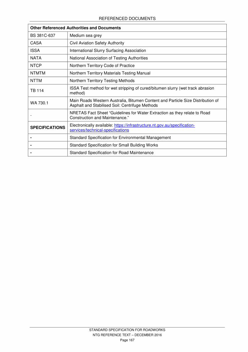
REFERENCED DOCUMENTS
STANDARD SPECIFICATION FOR ROADWORKS
NTG REFERENCE TEXT – DECEMBER 2016
Page 167
Other Referenced Authorities and Documents
BS 381C-637 Medium sea grey
CASA Civil Aviation Safety Authority
ISSA International Slurry Surfacing Association
NATA National Association of Testing Authorities
NTCP Northern Territory Code of Practice
NTMTM Northern Territory Materials Testing Manual
NTTM Northern Territory Testing Methods
TB 114 ISSA Test method for wet stripping of cured/bitumen slurry (wet track abrasion method)
WA 730.1 Main Roads Western Australia, Bitumen Content and Particle Size Distribution of Asphalt and Stabilised Soil: Centrifuge Methods
- NRETAS Fact Sheet “Guidelines for Water Extraction as they relate to Road Construction and Maintenance.”
SPECIFICATIONS Electronically available: https://infrastructure.nt.gov.au/specification-services/technical-specifications
- Standard Specification for Environmental Management
- Standard Specification for Small Building Works
- Standard Specification for Road Maintenance

REFERENCED DOCUMENTS
STANDARD SPECIFICATION FOR ROADWORKS
NTG REFERENCE TEXT – DECEMBER 2016
Page 168
26 ACTS, REGULATIONS AND CODES
Acts, Regulations and Codes applicable to the works and authorities with jurisdiction over the works include, but are not limited to;
ACTS & REGULATIONS Aboriginal Sacred Sites Act Bushfires Act Control of Roads Act Dangerous Goods Act and Regulations Environment Protection and Biodiversity Conservation Act Environmental Assessment Act Environmental Offences and Penalties Act Environment Protection and Biodiversity Conservation Act Fair Work Act 2009 Food Act 2004 Heritage Conservation Act NT Building Act and Regulations NT Planning Act and Regulations Poisons and Dangerous Drugs Act and Regulations Public Health (General Sanitation, Mosquito Prevention, Rat Exclusion and Prevention) Regulations Soil Conservation and Land Utilisation Act Territory Parks and Wildlife Act Territory Parks and Wildlife Conservation Act Traffic Act and Regulations Waste Management and Pollution Control Act Water Act Weeds Management Act Work Health and Safety Act and Regulations CODES AND GUIDELINES Building Code of Australia (BCA) CASA Directives CASA Manual of Standards NT Code of Practice for Small On-site Sewage and Sullage Treatment Systems and the Disposal or Re-use of Sewage Effluent. NT Deemed to Comply Manual NT Health and Safety Guidelines for Commercial Kitchens AUTHORITIES Aboriginal Areas Protection Authority (AAPA) Development Consent Authority of the NT (DCA) NT Department of Health NT Department of Environment and Natural Resources (DENR) NT Fire and Rescue Service (NTFRS) NT WorkSafe PowerWater Corporation of the NT (PWC) Requirements of the engaged Building Certifier Requirements of the Local Municipal or Shire Councils

REFERENCED DOCUMENTS
STANDARD SPECIFICATION FOR ROADWORKS
NTG REFERENCE TEXT – DECEMBER 2016
Page 169
27 CIVIL STANDARD DRAWINGS FOR ROADWORKS
Civil Standard Drawings for Roadworks
Note: Use the most recently issued versions of drawings.
CS 0016 Cross Section – Shared Path Railing at Culvert Crossing
CS 0601 Northern Territory Regions Map
CS 0602 Road Network – Darwin Region
CS 0603 Road Network – East Arnhem Region
CS 0604 Road Network – Katherine Region
CS 0605 Road Network – Tennant Creek Region
CS 0606 Road Network – Alice Springs Region – West
CS 0607 Road Network – Alice Springs - East
CS 1203 Standard Kerb Profiles
CS 1204 Cyclists’ Hold Rail
CS 1300 Flexible Guide Posts
CS 1301 Flood Gauge Posts
CS 1303 Standard Security Fence
CS 1306 Stock Fence Design and Details
CS 1310 Steel Beam Guard Rail
CS 1311 Standard Typical Approach Guardrail at Bridges
CS 1312 Standard Approach Guardrail Details for Single Lane Bridges
CS 1313 Standard Cattle Grid Plan and Sections with Approach Slab
CS 1314 Standard Cattle Grid Plan and Sections without Approach Slab
CS 1315 Standard Cattle Grid Details
CS 1316 Vehicle Movement Barriers
CS 1317 Standard Stock Fence Swinging Floodgate for Stream Crossings
CS 1500 Signal Details - Ducting
CS 1501 Signal Details - Pole Foundation
CS 1502 Signal Details - Mast Arm Foundation
CS 1503 Signal Details - Controller Foundation
CS 1504 Signal Details - Communication Isolation Pillar
CS 1505 Signal Detail Lantern Mounting Details
CS 1506 Pedestrian Push Button
CS 1507 Signal Detail Detector Installation
CS 1520 Line Marking
CS 1521 Chevrons and RRPM’s
CS 1550 Standard Traffic Counting Station Post Mounted Detector Loop and Pit Details
CS 1551 Standard Traffic Counting Station Post Mounted Detector Loop Layout
CS 1552 Standard Traffic Counting Station Post Mounted Piezo Tube Layout
CS 1553 Standard Traffic Counting Station Post Mounted Foundation Details
CS 1554 Standard Traffic Control Station Post Mounted Cabinet Wiring Details

REFERENCED DOCUMENTS
STANDARD SPECIFICATION FOR ROADWORKS
NTG REFERENCE TEXT – DECEMBER 2016
Page 170
Civil Standard Drawings for Roadworks
Note: Use the most recently issued versions of drawings.
CS 1555 Standard Traffic Counting Station Post Mounted Post Assembly
CS 1556 standard traffic counting station post mounted traffic cabinet details
CS 1557 Traffic Signal Advanced Warning Sign
CS 2100 8.0m Gravel Pavement Resurfacing - Typical Cross Section
CS 2101 Shoulder Maintenance Works - Gravel Pavement – Typical Cross Section B
CS 2102 Shoulder Maintenance on Various Width Sealed Pavement - Typical Cross Section
CS 2103 Shoulder Maintenance on Various Width Sealed Pavement - Typical Cross Section D
CS 2104 Road Maintenance Works 9m Gravel Pavement - Typical Cross Section
CS 2105 Road Maintenance Works 10m Gravel Pavement - Typical Floodway Cross Section
CS 2106 Road Maintenance Works 7m Sealed Pavement - Typical Floodway Cross Section G
CS 2107 Road Maintenance Works 9m Sealed Pavement - Typical Floodway Cross Section
CS 2108 Standard Specification 10m Carriageway with 8.0m seal – Typical Cross Section J
CS 2109 Standard Drawing 10.0m Carriageway with 8.0m seal – Typical Cross Section
B95-2284 (RU3A) Crow Guard Lid for 200L Drum
R09-3124 Irrigation - Telemetry Control Station Detail
Civil Standard Drawings Available: https://infrastructure.nt.gov.au/specification-services/standard-drawings

REFERENCED DOCUMENTS
STANDARD SPECIFICATION FOR ROADWORKS
NTG REFERENCE TEXT – DECEMBER 2016
Page 171

REFERENCED DOCUMENTS
STANDARD SPECIFICATION FOR ROADWORKS
NTG REFERENCE TEXT – DECEMBER 2016
Page 172

REFERENCED DOCUMENTS
STANDARD SPECIFICATION FOR ROADWORKS
NTG REFERENCE TEXT – DECEMBER 2016
Page 173
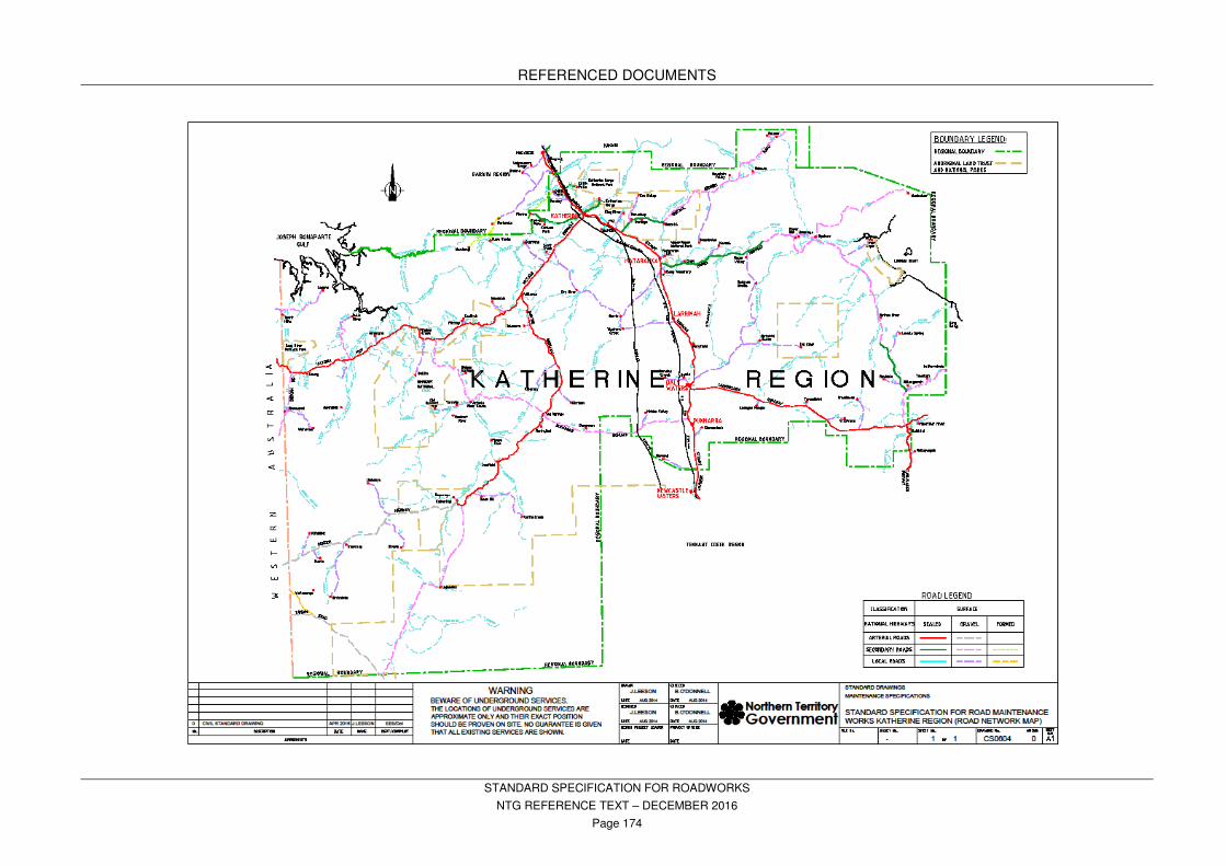
REFERENCED DOCUMENTS
STANDARD SPECIFICATION FOR ROADWORKS
NTG REFERENCE TEXT – DECEMBER 2016
Page 174
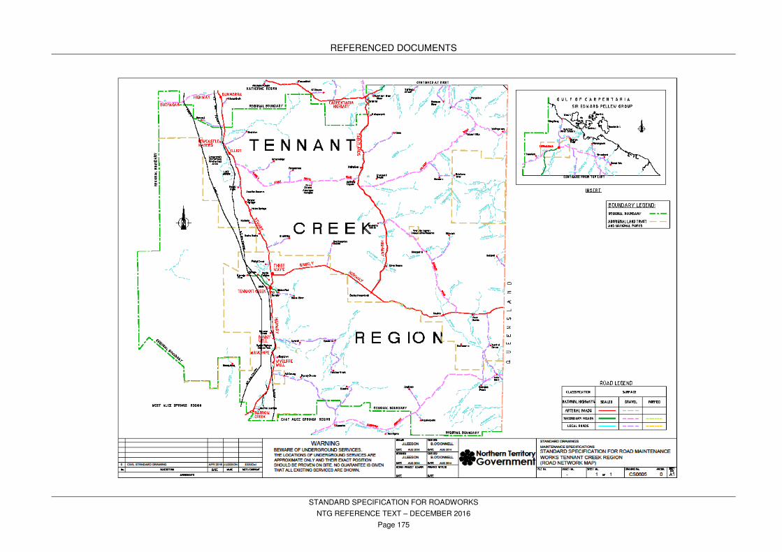
REFERENCED DOCUMENTS
STANDARD SPECIFICATION FOR ROADWORKS
NTG REFERENCE TEXT – DECEMBER 2016
Page 175

REFERENCED DOCUMENTS
STANDARD SPECIFICATION FOR ROADWORKS
NTG REFERENCE TEXT – DECEMBER 2016
Page 176

REFERENCED DOCUMENTS
STANDARD SPECIFICATION FOR ROADWORKS
NTG REFERENCE TEXT – DECEMBER 2016
Page 177

REFERENCED DOCUMENTS
STANDARD SPECIFICATION FOR ROADWORKS
NTG REFERENCE TEXT – DECEMBER 2016
Page 178

REFERENCED DOCUMENTS
STANDARD SPECIFICATION FOR ROADWORKS
NTG REFERENCE TEXT – DECEMBER 2016
Page 179

REFERENCED DOCUMENTS
STANDARD SPECIFICATION FOR ROADWORKS
NTG REFERENCE TEXT – DECEMBER 2016
Page 180
28 NORTHERN TERRITORY CLIMATE ZONES TABLE