Embed Size (px)
Citation preview

SCS USER GUIDE TB-9097
EM Aware Monitor
Installation, Operation and Maintenance (£)�
Figure 1. SCS 770066 EM Aware Monitor with standard antenna
Figure 2. SCS 770066 EM Aware Monitor with ionizer antenna
Description
The SCS 770066 EM Aware Monitor monitors three key parameters that keep you aware of critical symptoms of ESD problems: ESD events, change in static voltage field, and ionizer performance*. The thresholds for these parameters are fully adjustable. The monitor is constructed of an aluminum enclosure, LCD display, control joystick, remote antenna, relay terminal and Ethernet connectivity.
ESD events generate electromagnetic radiation. The stronger the ESD event, the stronger the electromagnetic radiation. The EM Aware Monitor is a miniature radio receiver tuned to detect and measure the unique waveform generated by an ESD event.
The EM Aware Monitor meets the Continuous Monitor requirements of ANSI/ESD S20.20 in accordance with ESD TR1 .0-01 and ANSI/ESD STM3.1. It meets the recommendations of ESD Handbook ESD TR20.20 which includes "if the products that are being produced are of such value that knowledge of a continuous, reliable ground is needed, and then continuous monitoring should be considered or even required".
*The ionizer must have a balance (offset voltage) of±40 V or better.
United States of America
The EM Aware Monitor and its accessories are available as the following item numbers:
Item Description
770066 EM Aware Monitor
CTC111-6FT Antenna, Room Temperature, 6 ft.
CTC118-6FT Antenna, High Temperature, 6 ft.
770064 Power Adapter, 100-240 VAC Input, 7.5 VDC 1.5 A Output, All Plugs
770055 SMP Software
II Static Management Program
The SCS 770066 EM Aware Monitor is compatible with SCS Static Management Program (SMP). SMP continuously monitors your ESD process control system throughout all stages of manufacturing. SMP captures data from SCS workstation, equipment and ESD event continuous monitors and provides a real-time picture of critical manufacturing processes. All activity is stored into a database for on-going quality control purposes. SMP allows you to pinpoint areas of concern and prevent ESD events. Quantifiable data allows you to see trends, become more proactive and prove the efficiency of your ESD process control system.
SMP is sold separately. Click here to learn more.
Packaging 1 EM Aware Monitor 1 CTC111-6FT Antenna with 6 ft. Cable 1 Interchangeable Ionizer Antenna 1 Monitor Ground Cord (Green and Yellow) 2 Ring Magnets 1 Ring Terminal 2 Screw, Flat Head, 4-40 x 3/8" 1 Screw, Pan-Head, 6-32 x 1/4" 1 Star Washer 1 Power Adapter, 7.5 VDC, with interchangeable plugs
(North America, UK/Asia, Europe, China) 1 Certificate of Calibration
TB-9097 Page 1 of 19 May 2019 © 2019 DESCO INDUSTR ES INC Employee OWned
Test Equipment Depot - 800.517.8431 - 99 Washington Street Melrose, MA 02176 - TestEquipmentDepot.com

Features and Components
A B C D E
F G
Figure 3. EM Aware Monitor features and components
A. Relay Terminal: Integrates with electronic tools,lights, buzzers, etc.
B. Antenna Input: Connect to the antenna using theincluded cable.
C. LCD Display: Displays measurements and settings.
D. Joystick: Toggles displayed measurements andmonitor settings.
E. Power Jack: Connect the included 7.5 VDC poweradapter here.
F. Ground Terminal: Common ground point for themonitor.
G. Ethernet Jack: Provides network communicationbetween the EM Aware Monitor and Static ManagementProgram {SMP).
Installation
Hardware Setup 1. Remove the monitor and antenna from the carton.
2. Determine the installation location of the remoteantenna. For optimal performance, position theremote antenna as close as practically possibleto the anticipated source of ESD activity. Use themounting tabs on the remote antenna to properlysecure it to the desired location.
3. If the remote antenna is to be used to monitor anionizer, replace the standard metal antenna ontop of of the remote's enclosure with the includedionizer antenna. The antennas may be screwed onand off. The ionizer antenna utilizes its increasedsurface area to capture more ions for measurement.
Figure 4. Replacing the standard antenna with the ionizer antenna
4. Connect the anntena's cable to the EM AwareMonitor without bending it.
5. Determine the mounting location of the monitor. Itsdisplay should be visible to the operator. Use thetwo 4-40 threaded holes at the back of its enclosureand the included ring magnets and 4-40 threadedscrews if desired.
I
I I
I I
I �---+----+----+----
I I
I I
I
I
1.60"
Figure 5. Mounting hole locations on the back of the EM Aware Monitor
6. Secure one end of the included ground cord tothe ground terminal located on the right-side ofthe monitor. Attach the other end of the cord to aground point. The face plate screw of a groundedAC wall outlet may provide a convenient connectionpoint.
7. Connect an Ethernet cable to the Ethernet jacklocated on the right-side of the monitor. Verify thatthe cable is properly connected to a network.
TB-9097 Page 2 of 19 © 2019 DESCO INDUSTR ES INC Employee OWned
8. Connect the power adapter to the power jacklocated on the right-side of the monitor. Route thewire from the power adapter to a nearby AC outletand plug it into the outlet. Make sure the voltageand frequency match those listed on the powersupply. The monitor is now powered.
Antenna
Figure 6. Stand-a/one setup for the EM Aware Monitor
Relay Terminal The EM Aware Monitor features one optical relay terminal that can be integrated with electronic tools, lights, buzzers, etc. The relay opens when the monitor enters an alarm condition, and it remains closed otherwise. Alarm conditions include ESD events and exceeded static voltage and ionizer balance thresholds.
Figure 7. Relay terminal pin-out
Parameter Rating
Peak Blocking Voltage 400 VP
Load Current 140 mArms
/ mAoc
On-Resistance (max) 22 ohms
TB-9097 Page 3 of 19 @ 2019 DESCO INDUSTR ES INC
Employee Owned
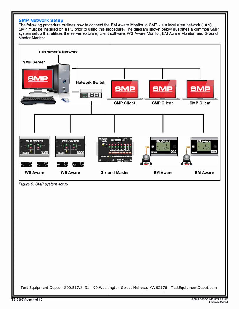
SMP Network Setup The following procedure outlines how to connect the EM Aware Monitor to SMP via a local area network (LAN). SMP must be installed on a PC prior to using this procedure. The diagram shown below illustrates a common SMP system setup that utilizes the server software, client software, WS Aware Monitor, EM Aware Monitor, and Ground Master Monitor.
Customer's Network
SMP Server I
Network Switch
, WSAwara •
I - ·-·• • I
• •·-·-·• . . .... .
-----·
_.. ...... .
-==.!. �
..... ���
WSAware
, WSAwara •
I - -·•. I • ·-·-·• . . ·-·
o. ......... �-·
-==..!. �
"WllllltW" � ��
WSAware
Figure 8. SMP system setup
SMP ----
SMP Client
Ground Master
• SMP ----
SMP Client
EM Aware
TB-9097 Page 4 of 19
.. SMP ----
SMP Client
EM Aware
@ 2019 DESCO INDUSTR ES INC
Employee Owned
Test Equipment Depot - 800.517.8431 - 99 Washington Street Melrose, MA 02176 - TestEquipmentDepot.com

DYNAMIC IP PROCEDURE
1. Verify that the Ethernet cable is securely connected to your network and EM Aware Monitor. The LEDs on theEthernet port will illuminate when a connection to the network is established.
2. Open SCS SMP Server Monitor.
s
-
�
::iMP
scs A
SCS SMP Admin
SCS SMP Client
!dMP SCS SMP Plan Editor
;;;_!Y'___!:! SCS SMP Server Monitor
3. The SMP Server icon will appear in the Windows taskbar.
SMP Server
version 2.0.6
S r,,1 PSe r•/er·M c n ito r
3:37 PM
2017-03-08
4. Click the SMP Server icon located on the Windows taskbar. The SMP Server menu will appear. Click the Startbutton to start SMP Server.
Ill SMP Server
version 2.0.6
Server status: Inactive•
Devices O , Act ive O 1,--
C-o_n_n_e_ct_ i _o_n_s.-.. -,
Close SMP Server Monitor
TB-9097 Page 5 of 19 © 2019 DESCO INDUSTR ES INC Employee OWned

5. A message will appear and display "Starting SMP Server. .. " Click the SMP Server icon located in the Windowstaskbar.
SMP Server
Starting SMP Server ...
s r, .. 1 PSer,:erM C 17 ito r
6. SMP Server will now indicate Active server status.
3:47 PM 2017-03-08
■SIMP Server
vers ion 2.0.6
I Server status: Active• I Device5 0 , Active O I Connections. ..
Close SMP Server Monitor
7. SMP Server will search and find the EM Aware Monitor on the network. The Device and Active counts willincrease to 1.
TB-9097 Page 6 of 19
■ SMP Server
ve,rsion 2.0.6
Server status: Active•
I Devices 1 , Active 1 I .-1 C _o_n_ n _e _c-tio_n_s.-.--,. I
�ose SMP Server Mani�
© 2019 DESCO INDUSTR ES INC Employee OWned

8. Open SCS SMP Admin.
s
II
�
OiMP
�
�
scs
SCS SMP Admin
SCS SMP Client
SCS SMP Plan Editor
SCS SMP Server Monitor
9. The window for SMP Server Admin will appear. "1 unassigned" is representative of the EM Aware Monitor thatwas just found by SMP Server. Click the Add New Building button.
II SMP Server Admin v.2.0.6
SMP Server local � ,_. �
SMP Server local
TB-9097 Page 7 of 19
Server local
buildings:O floors: 0 lines: 0 devices: 0 assigned. 1 unassigned
Buildings
D X
�hange S4'rver
login
�rver Qpbons
Ill I! Add t;(•w BuildiQg]
I ,•mail Notifocations I
I ConR4'ctions Status I
© 2019 DESCO INDUSTR ES INC Employee OWned
Test Equipment Depot - 800.517.8431 - 99 Washington Street Melrose, MA 02176 - TestEquipmentDepot.com

10. Enter a building name, and then click the OK button.
Add building to server local
Building name: !926 JR Industrial Drive
OK Cancel
11. The building name will appear on the navigation pane in SMP Server Admin.
1:1 SMP Server Admin v.2.0.6
SMP Server local � � �
" SMP Server local 926 JR Industrial Drive
&. r
Server local
buildings: 1 floors: 0 lin6:0 devices: 0 assigned, 1 unassigned
Buildings 926 JR Industrial Drive
12. Click on the building name in the navigation pane, and then click the Add New Floor button.
1:1 SMP Server Admin v.2.0.6
SMP Server local �
" SMP Server local • Ptiilhl@M!tftil•fflt 111111111
TB-9097 Page 8 of 19
&. r
Building 926 JR Industrial Drive
floor s: 0 lines: 0 devices: 0
Floors
D X
l;hange Server
1ogin
�rver Qp!lons
J.[sers
I i:•mail Notifications I
I Connections :itatus I
D X
I Bename Building (
I Qelete Building I
Add t::tew Floor I
© 2019 DESCO INDUSTR ES INC Employee OWned

13. Enter a floor name, and then click the OK button.
Ill Add floor to building 926 JR Industrial Drive
Floor name: '"'!L.1c.;;..;;;.bo;:;.;.r..;;.at;.;;o_.ry'--______________ _,
OK Cancel
14. The floor name will appear on the navigation pane in SMP Server Admin.
1:1 SMP Server Admin v.2.0.6
SMP Server local � � �
" SMP Server local " 926 JR Industrial Drive
Laborato,y
Building 926 JR Industrial Drive
floors: 1 lines: 0 d�ices:O
Floors Laborato,y
15. Click on the floor name in the navigation pane, and then click the Add New Line button.
1:1 SMP Seiver Admin v.2.0.6
SMP Server local �
" SMP Server local " 926 JR Industrial 0
111 ™
TB-9097 Page 9 of 19
Floor Laboratory
building 926 JR lndustnal Drive
lines: 0 d�ices:O
IJnes
D X
I Bename Building I
I Qelete Building I
[. Add_!
16. Enter a line name, and then click the OK button.
Add line to floor Laboratory
Line name: I PCB Assembly
OK Cancel
17. The line name will appear on the navigation pane in SMP Server Admin.
1:1 SMP Server Admin v.2.0.6
SMP Server local � � �
" SMP Server local " 926 JR Industrial Drive
" laboratory PCB Assembly
&. r
Floor Laboratory
building 926 JR Industrial Drive
lines: 1 devices: 0
Lines
a
D X
I Bename Floor I
Qelete Floor I
Edit flan I
._IPC_B_A_s_se_m_bl�y ___________________ �i rename � I Add Hew line I
18. Click on the line name in the navigation pane, and then click the Attachable Devices arrow located at thebottom of the window.
Im SMP Server Admin v.2.0.6
SMP Server local �
-' SMP Seiver local " 926 JR Industrial Drive
" laboroto� 1;;.1494,,me
TB-9097 Page 10 of 19
Line PCB Assembly
building 926 JR Industrial Drive floor �
devices: 0
Attached De111ces: Device Model Serial
D X
I Bename Line I
Delete Line I
© 2019 DESCO INDUSTR ES INC
Employee OWned

19. The serial number for the EM Aware Monitor will appear. Click attach.
Ill SMP StfVor Admin v.2.0.6
SMP Server local � -4> ,- 8 r j Cl A SMP Server local
Line PCB Assembly A 926 JR Industrial Drive
A laborat0fY PCB Assembly building 926 JR lndustnal Drive
floor laboratory
devices: 0
Attached Devices:
Device Model Serial
0 Attachable Devices:
Name Model Serial
[E4100400AAAA) EM Aware E4100400AAAA
20. The EM Aware Monitor will attach to the selected line.
11!1 SMP Server Admin v.2.0.6
SMP Server local � � ,- 8 C: A SMP Server local Line PCB Assembly
A 926 JR Industrial Drive A laboratory
PCB Assembly building 926 JR jndystri•I Drjye floor laboratory
devices: 1
Attached Devices:
De-vie� Model Senal
[E4100400AAAAJ EM Aware E4100400AMA
0 Attachable Devices:
Name Model Serial
TB-9097 Page 11 of 19
- D X
I Rename Line I
I Delete line I
f - D X
I Rename Line ! I .Q.elete Line I
rename detach
© 2019 DESCO INDUSTR ES INC Employee OWned
Test Equipment Depot - 800.517.8431 - 99 Washington Street Melrose, MA 02176 - TestEquipmentDepot.com

21. Open SCS SMP Client.
s
II scs
� SCS SMP Admin
OiMP SCS SMP Client
� SCS SMP Plan Editor
� SCS SMP Server Monitor
22. Verify that the EM Aware Monitor was added to the appropriate building, floor and line.
II SMP Device Monitoring v.2.0.6
Line:
Device
�.EMAware
TB-9097 Page 12 of 19
I
& Find device: ..__ _____ __,
Balance
Voltage
Static
Voltage
□ X
Alarms
order by: � �
© 2019 DESCO INDUSTR ES INC Employee OWned

Operation
WARNING: Never apply or discharge voltage directly to the EM Aware Monitor's metal remote antenna as this may cause significant damage to the EM Aware Monitor.
Controlling the EM Aware Monitor The EM Aware Monitor is controlled using a 5-position joystick located to the right of its display. The joystick can be toggled left, right, up, and down and pushed inward.
The EM Aware Monitor will default to the ESD Event display upon completion of its boot-up sequence. Toggle the joystick down to advance the display to the next channel, and toggle the joystick up to return to the previous channel. See Figure 9.
Push down and hold the joystick for 3 seconds to enter the displayed settings.
ESD Event
Static Voltage Field
Ionization Balance & Decay*
Sound On/Off
Smart Coefficient
- - -
... 18 I I U I :'v
...... . ...
♦
18 -280
•••••• Ufl •
♦ I 'J I.L
l/.8 1....... .
♦ m
5nd On
t -
lll ll ll 5[F
... "'
*Static voltage range must be set to 12.5 for this function screen to appear.
Figure 9. Cycling through the modes on the display
ESD Event Channel
REF . ESD Event -
n· Counting Mode
ESD Level �
Bar Graph
ESD ...... Threshold Mar1<er
..
-
18 I IU I
• • Let . �
Figure 10. ESD Event channel
MAX
� -PEAK
ESD Counter
• y
ESD Event Peaks
REF: Indicator appears during ESD event threshold setup.
ESD Event Counting Mode: Denotes that ESD event counting is active
ESD Level Bar Graph: Displays the current ESD level.
ESD Threshold Marker: Marks the ESD event threshold on the ESD level bar graph .
MAX: Indicates the maximum magnitude of ESD event within the last second duration.
PEAK: Indicates that the noise filter is enabled. If "PEAK" is not displayed, the noise filter is disabled.
ESD Counter: Counts the number of events over the set threshold. The maximum number is 1999 and resets to O once this limit is exceeded.
ESD Event Peaks: Voltage level that is received by the antenna which is a result of an ESD event near the antenna. It is measured in dBµV.
ESD Event Settings 1. Toggle the joystick until the ESD Event channel is
displayed (see Figure 10).
2. To reset the ESD counter to zero, push down thejoystick momentarily.
3. To change the ESD threshold, push down and holdthe joystick until "ESD" is displayed. The "REF"indicator will appear on the top-left corner of thedisplay to indicate that the ESD threshold value canbe modified. Toggle the joystick left to decreasethe threshold. Toggle the joystick right to increasethe threshold. Hold the joystick in either direction toquickly increment the value.
TB-9097 Page 13 of 19 © 2019 DESCO INDUSTR ES INC Employee OWned
1111
E5d I Ill I
I ....
Ill
•
I V
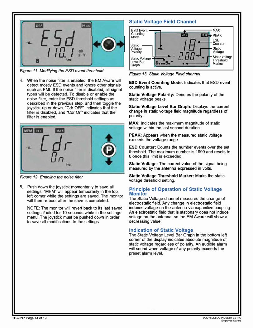
Figure 11. Modifying the ESD event threshold
4. When the noise filter is enabled, the EM Aware willdetect mostly ESD events and ignore other signalssuch as EMI. If the noise filter is disabled, all signaltypes will be detected. To disable or enable thenoise filter, enter the ESD threshold settings asdescribed in the previous step, and then toggle thejoystick up or down. "Cdr OFF" indicates that thefilter is disabled, and "Cdr On" indicates that thefilter is enabled.
=- -
...... [d,-on
Figure 12. Enabling the noise filter
5. Push down the joystick momentarily to save allsettings. "MEM" will appear temporarily in the topleft comer while the settings are saved. The monitorwill then re-boot after the save is completed.
NOTE: The monitor will revert back to its last savedsettings if idled for 10 seconds while in the settingsmenu. The joystick must be pushed down in orderto save all modifications to the settings.
Static Voltage Field Channel
Static Voltage Polarity
Static Voltage .... __ Level Bar Graph 11 ■■■l■un ·--------
Figure 13. Static Voltage Field channel
ESD Event Counting Mode: Indicates that ESD event counting is active.
Static Voltage Polarity: Denotes the polarity of the static voltage peaks.
Static Voltage Level Bar Graph: Displays the current change in static voltage field magnitude regardless of polarity.
MAX: Indicates the maximum magnitude of static voltage within the last second duration.
PEAK: Appears when the measured static voltage exceeds the voltage range.
ESD Counter: Counts the number events over the set threshold. The maximum number is 1999 and resets to 0 once this limit is exceeded.
Static Voltage: The current value of the signal being measured by the antenna expressed in volts.
Static Voltage Threshold Marker: Marks the static voltage threshold setting.
Principle of Operation of Static Voltage Monitor The Static Voltage channel measures the change of electrostatic field. Any change in electrostatic field induces voltage on the antenna via capacitive coupling. An electrostatic field that is stationary does not induce voltage on the antenna, so the EM Aware will show a decreasing value.
Indication of Static Voltage The Static Voltage Level Bar Graph in the bottom left corner of the display indicates absolute magnitude of static voltage regardless of polarity. An audible alarm will sound when voltage of any polarity exceeds the preset alarm level.
TB-9097 Page 14 of 19 © 2019 DESCO INDUSTR ES INC Employee OWned

Static Voltage Settings 1. Toggle the joystick until the Static Voltage channel
is displayed (Figure 13).
2. To reset the ESD counter to zero, push down thejoystick momentarily.
3. To change the voltage range and thresholds, pushdown and hold the joystick until "REF" is displayedon the top-left comer. "REF" indicates that thesettings can be modified.
4. Toggle the joystick up or down to scroll through thevoltage range options (12.5, 100,250,500, 1000volts). Select the 12.5 volt range to enable theionization balance function if desired.
5. Toggle the joystick left to decrease the threshold.Toggle the joystick right to increase the threshold.Hold the joystick in either direction to quicklyincrement the value.
6. Push down the joystick momentarily to save allsettings. "MEM" will appear temporarily in the topleft comer while the settings are saved. The monitorwill then re-boot after the save is completed.
NOTE: The monitor will revert back to its last savedsettings if idled for 10 seconds while in the settingsmenu. The joystick must be pushed down in orderto save all modifications to the settings.
Ionization Balance and Decay Channel
Ionization -....!i,i==,------
J.:
-� .. IonizationBalance Balance Polarity , , J 2 Decay_____ f. :r •Decay TimeMeasurement .�in Progress * -
U 8 1 • Ionization
Ionization -,_ Balance Balance Level I _ti .: Threshold Bar Graph ••• ••• • Marker
Figure 14. Balance and Decay Mode channel
Ionization Balance Polarity: Indicates the polarity of the ionizer's balance (offset voltage).
Decay Measurement in Progress: Appears when the decay time is being measured.
Ionization Balance Level Bar Graph: Indicates the balance (offset voltage) levels.
Ionization Balance: Displays the ionizer's balance ( offset voltage).
Decay Time: Displays the amount of seconds to decay a static charge. "1--.--" will display if the decay time exceeds 16 seconds.
Ionization Balance Threshold Marker: Marks the balance (offset voltage) threshold setting.
NOTE: The EM Aware Monitor is compatible with steady-state DC critical environment ionizers only. The ionizer must have a balance ( offset voltage) of ±40V or better.
Ionization Balance and Decay Settings NOTE: These settings cannot be changed unless the static voltage range is set to 12.5 volts. See "Static Voltage Settings" on page 15.
1. Toggle the joystick until the Ionization Balance andDecay channel is displayed (Figure 14).
2. Push down the joystick momentarily to manuallymeasure the ionizer's balance (offset voltage) anddecay time. The *- symbols will appear while themeasurements are being taken. The balance (upperrow) and decay time (lower row) will update atthe end of the tests. Balance and decay time areautomatically measured every three minutes. Staticvoltage monitoring becomes idle when balance anddecay tests are performed. ESD event monitoringoperates normally.
3. To change the voltage range and thresholds, pushdown and hold the joystick until "REF" is displayedon the top-left comer. "REF" indicates that thesettings can be modified. The value in the top rowindicates the current balance threshold, and thevalue in the bottom row indicates the decay timethreshold.
4. Toggle the joystick down to decrease the decaytime threshold. Toggle the joystick up to increasethe decay time threshold. Hold the joystick in eitherdirection to quickly increment the value.
dE [ .............. Decay Label
3. D ◄::-- Decay Time Threshold (seconds)
Figure 15. Decay time threshold settings
5. Toggle the joystick left to decrease the balancethreshold. Toggle the joystick right to increasethe balance threshold. Hold the joystick in eitherdirection to quickly increment the value.
TB-9097 Page 15 of 19 © 2019 DESCO INDUSTR ES INC Employee OWned

-Balance
lO w Threshold
bRL Balance Label '"
•
Figure 16. Ionization balance screen
6. Push down the joystick momentarily to save allsettings. "MEM" will appear temporarily in the topleft comer while the settings are saved. The monitorwill then re-boot after the save is completed.
NOTE: The monitor will revert back to its last savedsettings if idled for 10 seconds while in the settingsmenu. The joystick must be pushed down in orderto save all modifications to the settings.
Audible Alarm Settings 1. Toggle the joystick until the Sound channel is
displayed.
5nd On
Figure 17. Sound On/Off screen
2. To change the audible alarm setting, push downand hold the joystick until the setting below "Snd"blinks.
5nd 'n �
-un-, '
Figure 18. Sound On/Off change screen
3. Toggle the joystick left or right to disable or enablethe audible alarm.
4. Push down the joystick momentarily to save allsettings. "MEM" will appear temporarily in the topleft comer while the settings are saved. The monitorwill then re-boot after the save is completed.
Smart Coefficient (SCF) The Smart Coefficient (SCF) feature works in conjunction with the static voltage field channel. This feature is useful when an approximate voltage is desired, especially when the distance is not exact. For example, a known 1000 V static voltage source should show approximately 1000 V on the EM Aware Monitor when its antenna is 5 inches away from the static voltage source. This 1000 V approximation will change as the antenna is located further away from the static voltage source. It may show a value close to 600 V instead.
The Smart Coefficient function allows a correction factor to compensate for the variable distance. To bring the approximated voltage value back to 1000 V, the SCF value will have to be set to 1.66. Alternatively, if the antenna is moved closer, the monitor may show 1400 V. In this case, an SCF value of 0.71 will bring the reading back to 1000 V.
NOTE: All numbers referenced in the previous paragraph are for illustration purposes only. They should not be referenced for accuracy.
The Smart Coefficient has a default setting of 1.000, and it can be adjusted from 0.001 to 1.999. When adjusting the Smart Coefficient, it is important to have a known static voltage source as a reference for setting the SCF value. This voltage source may be a Pulse Generator, a Charged Plate Monitor (1 kV typically), or a Function Generator.
Smart Coefficient (SCF) Settings 1. Toggle the joystick until the Smart Coefficient
channel is displayed.
,nnn I.LJ LJ LJ
5[F
Figure 19. Smart Coefficient channel
2. To change the Smart Coefficient value, push downand hold the joystick until the value blinks and"REF" is displayed on the top-left corner. "REF"indicates that the settings can be modified.
TB-9097 Page 16 of 19 © 2019 DESCO INDUSTR ES INC Employee OWned

,. ,
-lll ll 0-, 5[F'
Figure 20. Setting the Smart Coefficient value
3. Toggle the joystick left to decrease the value.Toggle the joystick right to increase the value. Holdthe joystick in either direction to quickly incrementthe value.
4. Push down the joystick momentarily to save allsettings. "MEM" will appear temporarily in the topleft comer while the settings are saved. The monitorwill then re-boot after the save is completed.
NOTE: The monitor will automatically save the valueon the display if idled for 10 seconds while in thesettings menu.
Figure 21. Using the EM Aware Monitor with standard antenna inside of a pick-and-place machine
/\ / l
_¢mi
Figure 22. Using the EM Aware Monitor with ionizer antenna on a workbench with the SCS 770112 Ion Pro™
Overhead Ionizer
Figure 23. Using the EM Aware Monitor with ionizer antenna on an SMT conveyor with the SCS 963E Benchtop Air Ionizer
TB-9097 Page 17 of 19 © 2019 DESCO INDUSTR ES INC Employee OWned
Test Equipment Depot - 800.517.8431 - 99 Washington Street Melrose, MA 02176 - TestEquipmentDepot.com

Figure 24. Using the EM Aware Monitor with ionizer atenna inside of a pick-and-place machine with the SGS 960 Mini Air Ionizer
EM Aware Calculator Software
Use the EM Aware Calculator to estimate ESD event voltages. Simply enter the dBµV measurement from the EM Aware Monitor and the distance from the event source to the remote antenna. The EM Aware Calculator will provide an approximate voltage for the ESD event based on COM, HBM and MM models.
1. Use the link below to download the EM AwareCalculator Software.StaticControl.com/Downloads/EMAwareCalculator.zip
2. Extract the contents of the zip folder, and run"setup.exe". Follow the on-screen prompts to installthe software.
3. Run the EM Aware Calculator to estimate ESDevent voltages based off dBµV measurements fromthe EM Aware Monitor and distance settings.
,.,. EM Aware TNG Calculator V3.0.3
Model
Q Machine Model
.Artenna
0 Loeal
@ Remote Q HLman Body Model
@ Olarge Oeviee Model
Parameter
EM Aware linear voltage
0.001V
Distance
'
0.5 15
EM Aware LCD or SMP dBµV Vl!lue
'
Estimated true ESD voltage
4V
0 . .5 �nch) 1.27 (em)
60.0 (dllµV) LCD/SMP re11cing
1.00 (Vol) OATAQ readinQ
X
60.0 134.0
<i' 2015 Deseo lndusbies
Figure 25. EM Aware Calculator Software
TB-9097 Page 18 of 19 © 2019 DESCO INDUSTR ES INC Employee OWned

Maintenance
Cleaning Disconnect the power adapter from the device. Clean the EM Aware Monitor and its antenna using a dry brush or vacuum cleaner. Clean its contacts using a contact cleaner or brush, and tighten all connections. Do not reconnect the power adapter until cleaning is finished.
Repairs and Servicing There are no user-serviceable parts. Do not attempt to repair the EM Aware Monitor yourself. Contact an SCS sales representative or authorized distributor to request inspection and repair.
Calibration
Contact an SCS sales representative or authorized distributor to request product calibration if necessary.
Specifications
Power
Power Adapter 100-240 VAC50-60 Hz
ESD Event Monitor
Output: 7 .5 voe @ 1.5 A Output Plug Polarization: Center Positive Output Plug: 5.5 mm O.D. x 2.1 mm I.D. x 9.5 mm L
Measurement Magnitude ESD Event
ESD Event Default setting: 80 dBµV Threshold
Raw Input Signal 60 dBµV (~1mV) to 134 dBµV (~5.0 V)
Filtering Function ESD
Static Voltage Monitor
Measurement
Static Voltage Setting Range
Output
Static Voltage - Change of electrostatic field
12.5 V, 100 V, 250 V, 500 V, 1000 V, smart coefficient adjust
Ethernet
Ionizer Voltage and Decay Monitor
Compatible Ionizer Steady-State DC
Max. Decay Time 16 seconds** max, typical Reading
Max. Decay Test ±5 V Voltage
Connectivity
Input SMA Connector for Remote antenna
Outputs RJ45 connector for Ethernet output; 2-position terminal block for relay output
General
Alarm
Display
Dimensions (antenna not included)
Weight
Buzzer
LCD
3.17" W x 2.25" H x 1.26" D (81 mm W x 57 mm H x 32 mm D)
183 g
**The readings of ionization voltage and decay under identical conditions may not always correlate with a charged plate monitor. The EM Aware Monitor is not intended to replace regular testing of ionizers by a charged plate monitor.
Limited Warranty, Warranty Exclusions, Limit of
Liability and RMA Request Instructions
See the SCS Warranty -StaticControl. com/Limited-Warranty .aspx
TB-9097 Page 19 of 19 © 2019 DESCO INDUSTR ES INC Employee OWned
Test Equipment Depot - 800.517.8431 - 99 Washington Street Melrose, MA 02176 - TestEquipmentDepot.com