Embed Size (px)
Citation preview

SSP-8080
REMOTE PROGRAMMABLE POWER SUPPLY WITH
ETHERNET NETWORK CONNECTIVITY DC WAVE FORM GENERATOR
3 SELECTABLE VOLTAGE & CURRENT RANGES
USER MANUAL
Rev.4 2013/12 7673-8080-0004

CONTENTS 1. INTRODUCTION P.1 2. PRECAUTIONS P.2 3. SPECIFICATIONS P.3 4. INDICATORS AND CONTROLS P.4 ~ P.7 4.1 Front Panel Push Buttons and Volume Knob 4.2 LED Indicators 4.3 Back Panel 5. OPERATION PROCEDURES P.8 ~ P.10 5.1 Selecting the V I Range 5.2 Adjusting Output Voltage and Current 5.3 Setting the 3 Voltage & Current Recalls 5.4 ΔV/Δt Function 5.5 Func A/B/C and Wave Form Generator 6. UVL , UCL , DISP/CAL FUNCTIONS P.11 6.1 Adjusting the UVL (Upper Voltage Limit) and UCL (Upper Current Limit) 6.2 The DISP button --- changing the current display to watt display 6.3 The CAL button 7. REMOTE CONTROL FUNCTIONS P.11 ~ P.13 7.1 Activate the Remote Control Mode 7.2 Exit from the Remote Control Mode 7.3 Remote Control Terminal Allocations 7.4 Remote control methods and connections 8. REMOTE SENSING OPERATIONS P.13 9. OVER TEMPERATURE AND OVER VOLTAGE TRACKING PROTECTION P.13 10. PC INTERFACE AND REMOTE PROGRAMMING SOFTWARE P.14 ~ P.18 10.1 EXTERNAL TIMED PROGRAM 11. MORE OPERATION EXAMPLES P.19 ~ P.23 11.1 Examples of Func A/B/C and Wave Form Generator 11.2 In case calibration 12. SOFTWARE CONFIGURATION and NETWORK SETTING P.23 ~ P.31 12.1 PC and Ethernet module connection test 12.2 Configure PC 12.3 Configure PC’s IP address 13. APPENDICES P.32 ~ P.39 13.1 Look up table for voltage recalibation 13.2 Look up table for current recalibation 13.3 Command Sets
13.4 Operation Mode Description
13.5 List of default ports that are assigned by TCP and UDP 13.6 IPORT-1 module speed test result
P.1

1. INTRODUCTION This is a power supply for the R&D, burn-in-test, laboratory work with repetitive cyclic operation at different voltage, current and cycle time. It can be programmed, controlled by a stand alone PC or via the Ethernet remotely controlled, monitored and data logged. The DC ramp and wave form generator can either be panel set or by the supplied software with preview of final waveform. When use as a bench top power supply, the tuning of voltage and current is ever so precise in step 1Vor 0.1V and 0.1A or 0.01A. Furthermore it can also be fully remotely controlled without the PC as well.
P.2

2. PRECAUTIONS
Keep this manual in a safe place for quick reference at all times.
This manual contains important safety and operation instructions for correct use of the power supply. Read through the manual and pay special attention to
the markings and labels of this unit and equipment to be connected.
Pay special attention to these two types of notices used in this manual
WARNING : Failure to observe this warning may cause injury to persons and damage to power supply or connected equipment.
CAUTION : Failure to observe this warning may result in damage to equipment and
Improper functioning of the power supply.
WARNING : 1. Do not use this power supply near water. 2. Do not operate or touch this power supply with wet hands. 3. Do not open the casing of the power supply when it is connected to ac mains. 4. Refer all servicing to qualified service personnel only. 5. Before replacing the AC fuse find out and clear up the cause first. 6. Replace the AC fuse with the same type and rating as the original fuse.
CAUTION : 1. Use a grounded 3 pin AC source . 2. This unit is for indoor use only . 3. Do not operate or place this unit in a humid, dusty, in direct sunlight location or near any heat
source. 4. Before plugging into local AC mains, check with the rating label at the back of the unit. 5. Do not block any ventilation openings of the unit. 6. This unit must be used within the specified rating, regular excessive continuous over loading
may cause damage to the power supply. 7. The gauge size of input power cable must be at least 0.75mmsq and the total length of power
cable must not exceed 3m. 8. Input Fuse Recommended: T2AL250V (Time-Lag from 2A)
Operation environmental condition : 10-80% R.H. Altitude up to 2000m Installation category : CAT 2 Pollution degree : 2 Mains supply voltage fluctuation up to ±10% of the specified operating voltage.
P.3

3. SPECIFICATIONS
Input AC voltage range 100-240V AC
No load input current (230V) <=130mA
Full load input current (230V) <=0.5A
Input AC Frequency 47 ~ 63Hz
Efficiency(Output 16V/5A With Optimal Load) 80%
Power Factor >=0.9
Constant Voltage Characteristics
Load Regulation(0 ~ 100% ) <=20mV
Line Regulation (± 10%) <=4mV
Ripple & Noise (P-P) <=30mV
Output Voltage Range per Selection
0~16V / 5A Selection I 0 ~16.4V
0~27V / 3A Selection II
0 ~ 27.6V
0~36V / 2.2A Selection III
0 ~ 36.8V
Constant Current Characteristics
Load Regulation(0 ~ 100% ) <=10mA
Line Regulation(± 10% ) <=10mA
Output Current Range per Selection
0~16V / 5A Selection I 0 ~ 5.1A
0~27V / 3A Selection II
0 ~ 3.1A
0~36V / 2.2A Selection III
0 ~ 2.3A
Meter Accuracy
Voltmeter Accuracy Output V<=5V ±0.5% +5counts
Output V>5V ±0.5% +3counts
Ammeter Accuracy Output I<=2A ±0.5% +5counts
Output I>2A ±0.5% +3counts
Protection
Tracking Over Voltage Protection, Current Limiting Protection ( Short Circuit , Overload), Over Temperature Protection
CE Approvals LVD: EN 61010 EMC: EN 55011, 61000
Size (W * H * D) 53*136*330 mm
Weight Approx. 2.1 kg
User Adjustable UVL(Up Voltage Limit) , UCL(Up Current Limit) Yes
Remote Sensing Yes.
Remote Analog Control Interface Yes
Number of Quick Preset Recalls of frequent use V& I setting 3
Ramp Function Generators(RFG) Yes
Wave Form Generation Function Yes
Standard Communication Port USB 2.0
Optional interface accessory Ethernet control board (IPORT-1) factory pre-installed or user installable.
Provided Software Application Software ,USB Driver , Command Sets , Labview driver for Ethernet Interface

4. INDICATORS AND CONTROLS
P.5
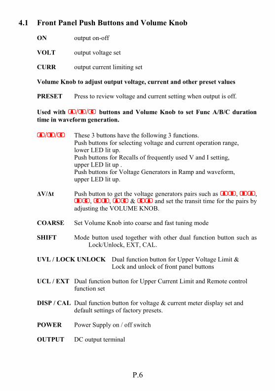
4.1 Front Panel Push Buttons and Volume Knob ON output on-off
VOLT output voltage set CURR output current limiting set
Volume Knob to adjust output voltage, current and other preset values PRESET Press to review voltage and current setting when output is off.
Used with // buttons and Volume Knob to set Func A/B/C duration
time in waveform generation.
// These 3 buttons have the following 3 functions.
Push buttons for selecting voltage and current operation range, lower LED lit up. Push buttons for Recalls of frequently used V and I setting, upper LED lit up . Push buttons for Voltage Generators in Ramp and waveform, upper LED lit up. ΔV/Δt Push button to get the voltage generators pairs such as , , , , & and set the transit time for the pairs by adjusting the VOLUME KNOB. COARSE Set Volume Knob into coarse and fast tuning mode
SHIFT Mode button used together with other dual function button such as Lock/Unlock, EXT, CAL. UVL / LOCK UNLOCK Dual function button for Upper Voltage Limit & Lock and unlock of front panel buttons UCL / EXT Dual function button for Upper Current Limit and Remote control function set DISP / CAL Dual function button for voltage & current meter display set and default settings of factory presets. POWER Power Supply on / off switch OUTPUT DC output terminal
P.6

4.2 LED Indicators Fault Over temperature protection or tracking OVP is triggered.
UVL Upper voltage limit protection at the output is triggered UCL Upper current limit protection at the output is triggered
EXT Power supply is under remote program control W Ampere meter becomes a Watt meter (Cal button) A Ampere meter CC Constant current mode CV Constant voltage mode
RMT / LOCK Panel control buttons lock up or PS in remote program mode 16V / 5A power supply V I range is selected at 16V , 5A 27V / 3A power supply V I range is selected at 27V , 3A 36V / 2.2A power supply V I range is selected at 36V , 2.2A
P.7

4.3 Back Panel
USB communication port Remote sensing terminals
DC output terminal which has same power rating as the front output
Selector Switch for USB and ETHERNET.
Switch up for USB ; Switch down for Ethernet .
Terminal for remote control of VI range, output on-off, V & I volume. (See section 7)
RJ45 communication port for Ethernet .
AC INPUT SOCKET
P.8

5. OPERATION PROCEDURES
5.1 Selecting the V I Range
First press and hold SHIFT button, then press the desired // button.
Note the respective lower VI range LED lights up to confirm the selected range. Changing the V I Range will change all the Recalls settings, output v to zero and the setting value of output I to the maximum value of the range.
5.2 Adjusting Output Voltage and Current 1. Push down the VOLT or CURR button. 2. Check its LED indicator before adjusting Volume Knob. For fast tune, press and hold the COARSE button and turn the VOLUME Knob. Voltage increases by 1.0V step and Current by 0.1A step in coarse tune. For fine tune, press and hold the PRESET button and turn the VOLUME Knob. Voltage increases by 0.1V step and Current by 0.01A step in fine tune .
Note : The power supply retains the final output values of the voltage, current and VI range setting even after it is switched off.
5.3 Setting the 3 Voltage & Current Recalls 3 frequently used output voltage and current limit values can be quickly accessed at
one touch of the buttons //.
Press to select any one of // button and note its LED indicator A, B, C.
Adjust the output V and I to the desired values using steps in procedures 5.2. Repeat for remaining the two Recalls . Note: All three recalls must be in the same V I Range (16V,5A ; 27V,3A ; 36V,2.2A) Changing the V I Range will erase all Recalls settings & output voltage to zero and the setting value of output I to the maximum value of the range.
5.4 ΔV/Δt Function There are 3 settable DC voltage generators , namely A, B, and C . ΔV a-b means from voltage level A to voltage level B. Δt a-b means time in seconds from voltage level A to level B, this transit time is adjustable from 0 to 20 seconds.
P.9

5.4.1. Presetting the DC generator voltage level There are 3 generator voltage levels that can be preset, namely A / B and C
First press to select // and note its LED, then adjust voltage as given in procedure 5.2.
5.4.2. Presetting the Δt There are 6 sets of available Δt short presses on the ΔV /Δt button will show the cyclic sequence of AB → BA → BC → CB → AC → CA → AB. We use the AB as an example Click the ΔV/Δt button until “A-b” appears on the lower LED display then hold the button, at the same time, turn the volume knob to set to desired transit time Δt say 5sec.
5.4.3. Generating the Ramp Up or Down DC output Ramp up generator example Set A = 5V B = 10V , Δt a-b = 5 seconds Now connect a suitable load to the output and turn on the output terminal by pushing the OUTPUT ON button and note the output LED indicator. Push Button note the output voltage of 5V and then push Button note output voltage rises to 10V in 5seconds showing a ramp up voltage, the output will stay at 10V level. Now pushing the Button now will generate a ramp down voltage from 10V to 5V in 5 seconds and stays at the 5V level. Note: The final output voltage level will be at the last voltage level generator.
5.5 Func A/B/C and Wave Form Generator The Func A/B/C sets how long (0 to 600sec) the voltage generator stays on at the specified output voltage level before going to other voltage level. To set the Func A/B/C , press and hold both the PRESET button and the button
//and at the same time turn the Vol. Knob to set the duration time period
(0 to 600 seconds)for the chosen voltage level.
P.10 P.11

To generate waveform, the Func A/B/C is used in conjunction with ΔV/Δt (the time from one voltage level to another voltage level) By using the above functions simultaneously, 3 reversible pair (AB & BA, BC & CB, AC & CA ) can be used to generate waveform . Example 1 : Pulse waveform with 3sec at 10V and 1sec at 5V . set A = 5V , set B = 10V set Func. A = 1 seconds by press & hold the PRESET button and button and at the same time, turn the volume knob. Func B = 3 seconds using the same procedure as above Set Δt a-b = 0 , Set Δt b-a = 0 Generating Wave Form To generate the waveform push buttons and at the same time . The waveform will repeat cyclically until either or button is pressed again .
Example 2 : Triangular wave form Set A = 5V , B = 10 V Set Δt a-b = 3 seconds , Set Δt b-a = 3 seconds Set Func. A = 3 seconds , Set Func. B = 3 seconds Note : The waveform generation can be operated via our remote programming software with preview of the waveform and data logging of the output in graphical presentation as well. See section 10.
This is a rather tricky operation, check the 2 LED carefully to see if both are lit up and one is flashing. The flashing will jump from one to the other, A to B, then B to A .
If the above does not happen, push both buttons and simultaneously again
until the above happens. The waveform will repeat cyclically until either or button is pressed again .
P.12

6. UVL , UCL , DISP/CAL FUNCTIONS
6.1 Adjusting the UVL (Upper Voltage Limit) and UCL (Upper Current Limit) When the voltage or current at the output terminal exceeds the set limiting values, the output will be cut off. These additional protection features are necessary for a power supply with such a wide ranges of voltage and current. Press and hold the UVL button, tune the VOLUME knob, the upper LED indicator shows the UVL voltage values. Press and hold the UCL button, tune the VOLUME knob, the lower LED shows the UCL current values.
6.2 The DISP button --- changing the current display to watt display Short press at the DISP button will change the lower LED display from Amp (red) reading to Watt (green) reading.
6.3 The CAL button The calibration function is initiated when the CAL button is pressed simultaneously with the SHIFT button. Do not perform this function unless calibration is required.
7. REMOTE CONTROL FUNCTIONS The remote control terminal at the back of the power supply can be used to control the Output on-off, voltage and current volume, and selection of VI range.
7.1 Activate the Remote Control Mode Press and hold the SHIFT button and at the same time press the EXT button. The green LED of EXT and the PMT/LOCK will light up indicating power supply is in Remote Control Mode. All the control buttons, and volume knob become inactive and locked except the SHIFT and EXT buttons.
7.2 Exit from the Remote Control Mode Keep SHIFT button pressed down, first press the Local/Lock button to release the Lock on the control buttons and volume knob. Press the SHIFT button + EXT button to exit from the Remote Control Mode. The green LED of the SHIFT and EXT will be off to confirm complete exit from the Remote Control Mode.
P.13

7.3 Remote Control Terminal Allocations Position of 10 insert slots Control Signal Scheme Control Signal Applications
1 OUT_EN Output On-Off Signal ON: no connection , isolated OFF: pin 4 connected to ground
2 SELECT 0 Selection of VI Ranges 16V/5A: PIN2,PIN3 and PIN 4 TO ground 27V/3A:PIN2 no connection, PIN3 to Pin 2 open Pin 3 to ground 36V/2.2A: Pin3 open
3 SELECT 1
4 DGND Control Signal Ground
5 2.5V reference voltage To resistor in remote control circuit
6 2.5V reference voltage To resistor in remote control circuit
7 CC CNT remote control for constant current
8 CV CNT remote control for constant voltage
9 AGND simulated ground signal
10
7.4 Remote control methods and connections Remote control for CC (constant current) current and CV (constant voltage) voltage adjustment can be performed by using the internal voltage source and external variable resistor. a. Output voltage control CV
b. Output current limiting control CC
P.14

Remote control for CC (constant current) current and CV (constant voltage) voltage adjustment can be performed by using an variable external of DC voltage source of 0 to 2.5 V. a. Output voltage control CV b. Output current limiting control CC
Remarks: PIN 5, PIN 6, PIN 7, PIN 8, PIN 9 are analog signal interface for remote control.
8. Remote Sensing Operation When the output current is large or long cable to load, there is a voltage drop across the connecting cable such that the voltage at load point is less than at the output terminal of the power supply. By making an extra connection from the remote sensing terminal SENSOR to the load point (Attention: do not reverse polarity) will make up for the load line voltage drop and make the voltage at the load point and output terminal the same. (Make sure to disconnect the wiring to remote sensing first before disconnecting the main output connection)
9. Over Temperature and Tracking Over Voltage Protections
When either the temperature inside the power supply exceeds a preset value or the output voltage is higher than adjusted values, the protection circuitry will be triggered and the output will be cut off. A Buzzer alarm and the FAULT led will be on at the same time. The set points of Tracking Over Voltage; For adjusted output voltage Va of less or equal to 10V, tracking OVP is set at Va+1 V. For adjusted output voltage Vb of more than 10V, tracking OVP is set at Vb X 1.1 V.
P.15

10. PC Interface and Remote Programming Software 1. Install the software by first insert the CD into CD Rom of your PC. 2. Locate and click the Setup file. 3. After completion of the installation of software then connect the SSP-8080 to the PC either via the USB Port or the RJ45 Port (with optional Ethernet card) checking the correct position of the USB / Ethernet Selector Switch. 4. Connect the output terminal of the SSP-8080 to a suitable load. 5. Start the application software of SSP-8080 on your PC, the following window dialog will appear.
Click and Select
“Single”
P.16

6. Press “Setting” tab. 7. V I Range Selection to choose. Data log Sampling Time at the drop down slot. PC interface for either USB or Ethernet as set at the SSP-8080. Enter the IP address if using the Ethernet connection.
P.17

Example of preview wave form
P.18 P.19

10.1 External Timed Program The unit can be externally programmed via a PC to run 20 steps each with a preset voltage, current limiting value and a preset time period of 1 second to 99 minutes. The timed program can be set to run from one cycle to infinite cycles. External Timed Program Window
P.20

Clear Table Delete all data in the Display Table and ready for new data entry. Run (Stop) To run and stop the Timed Program Running Cycle: Enter the number of desired running cycles here. The range of the number is 0-999. However the maximum cycles can be set to infinite when “0” cycle is entered. External Timed Program allows user set the output either ON or OFF by selecting the boxes in the last column. Output ON/OFF: 1. Output ON Ticked: Output is ON for that step 2. Output ON Un-ticked: Output is OFF for that step. Operation Procedure 1. Clear old data in the table, click [Clear Table]. 2. Enter data in the table using the 'Up Down Left Right' keys of your PC keyboard for new locations. 3. Data exceed the rated voltage and current will not be accepted. 4. Voltages exceed set UVL (Upper Voltage Limit) will not be accepted. 5. If retrieved or entered data exceed preset Upper or Lower Limit setting of voltage / current / time periods, the data will becomes red in colour and cannot be accepted . 6. When the running time period of any of the step is set at zero minute and zero second, this step becomes the terminating step and the cycle will end at that step. In the above example there are 4 steps each with 2 sec period, if step 3 is set to zero minute & second, the program only cycles around step1 and 2 and will not go to step 4. 7. Enter the number of desired running cycles. 8. click [Run] to run the External Time Program. External Timed Program allows user set the output either ON or OFF by selecting the boxes in the last column.
P.21

11. MORE OPERATION EXAMPLES 11.1 Examples of Func A/B/C and Wave Form Generator
Example 3 Irregular waveform Set A= 5V , B= 10 V Set Δt a-b = 1 second , Set Δt b-a = 2 seconds Set Func. A = 3 seconds , Set Func.B = 3 seconds Example 4 Irregular waveform Set A= 5V , B= 10 V Set Δt a-b = 2 second , Set Δt b-a = 2 seconds Set Func. A = 2 seconds , Set Func.B = 6 seconds Example 5 Irregular waveform Set A= 5V , B= 10 V Set Δt a-b = 2 second , Set Δt b-a = 0 seconds Set Func. A = 4 seconds , Set Func.B = 3 seconds Example 6 Irregular waveform Set A = 5V , B = 10 V Set Δt a-b = 4 second , Set Δt b-a = 4 seconds Set Func. A = 2 seconds , Set Func .B = 2 seconds
P.22
11.2 In – Case Recalibration This in-case recalibration is to reduce: 1. the difference between set value and the actual output value from the output terminal. (see section 11.2.2) Note: You only do section 11.2.2 when the difference is greater than 0.1V for voltage and 0.01A for current 2. the difference between set value and the LED Display value. (see section 7.3) Note: You only do section 11.3.3 when the difference is greater than 0.1V for voltage and 0.01A for current The calibration is divided to three sect (CALb0, CALb1,CALb2) or eliminating the nonlinear error for both voltage and current. The three calibration sects are partitioned according responding voltage and current value as follow. Voltage: CALb0 0=< Voltage<=16.4V CALb1 16.4<Voltage<=27.6V CALb2 27.6V< Voltage Current: CALb0 0=<Current<=0.3A CALb1 0.3A<Current<=4.8A CALb2 4.8A<Current
11.2.1 Recalibrating the Set Value and the Actual Output Value
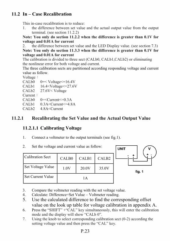
11.2.1.1 Calibrating Voltage 1. Connect a voltmeter to the output terminals (see fig.1). 2. Set the voltage and current value as follow:
Calibration Sect CALB0 CALB1 CALB2
Set Voltage Value 1.0V 20.0V 35.0V
Set Current Value 1A
3. Compare the voltmeter reading with the set voltage value. 4. Calculate: Difference=Set Value – Voltmeter reading.
5. Use the calculated difference to find the corresponding offset value on the look up table for voltage calibration in appendix A. 6. Press the “SHIFT” +“CAL” key simultaneously, this will enter the calibration mode and the display will show “CALb 0”. 7. Using the knob to select corresponding calibration sect (0-2) according the setting voltage value and then press the “CAL” key.
P.23

8. Using the knob to select “CAL D-A” and then press the “CAL” key to confirm. 9. Using the knob to select “d-AE” for voltage actual output calibration, and then press the “CAL” key. 10. The display will show “AdxE OFSt” (x:0-2) ,press the “CAL” key to confirm. 11. Input the offset value you find on the look up table by turning the knob and press “CAL” key to confirm.(The increase or decrease value for every step is 10 when press the “COARSE” key simultaneously while turning the knob.)
11.2.1.2 Calibrating Current 1. Prepare an ammeter and make sure it can measure up to 5.5A. 2. Connect the ammeter to the unit (see fig. 2). Set the voltage and current value as follow:
Calibration Sect CALB0 CALB1 CALB2
Set Current Value 0.2A 2.0A 5.0A
Set Voltage Value 15V
3. Compare the ammeter reading with the set current value. 4. Calculate: Difference=Set Value – ammeter reading. 5. Use the calculated difference to find the corresponding offset value on the look up table for current calibration in appendix B. 6. Press the “SHIFT” +“CAL” key simultaneously, this will enter the calibration mode and the display will show “CALb 0”. 7. Using the knob to select corresponding calibration sect (0-2) according the setting current value and then press the “CAL” key. 8. Using the knob to select “CAL D-A” and then press the “CAL” key to confirm. 9. Using the knob to select “d-AC” for current actual output calibration, and then press the “CAL” key. 10. The display will show “AdxC OFSt” (x:0-2) ,press the “CAL” key to confirm. 11. Input the offset value you find on the look up table by turning the knob and press “CAL” key to confirm.(The increase or decrease value for every step is 10 when press the “COARSE” key simultaneously while turning the knob)
P.24

11.2.2 Recalibrating the Actual Display and the LED Display Value
11.2.2.1 Calibrating Voltage 1. Connect the voltmeter to output terminals (see fig.1). Set voltage and current value as follow:
Calibration Sect CALB0 CALB1 CALB2
Set Voltage Value 1.0V 20.0V 35.0V
Set Current Value 1A
2. Compare the voltmeter reading with the LED voltage display value. 3. Calculate: Difference= Voltmeter reading - LED Voltage Display. 4. Use the calculated difference to find the corresponding offset value on the look up table for voltage calibration in appendix A. 5. Press the “SHIFT” +“CAL” key simultaneously, this will enter the calibration mode and the display will show “CALb 0”. 6. Using the knob to select corresponding calibration sect (0-2) according the setting voltage value and then press the “CAL” key. 7. Using the knob to select “CAL A-D” and then press the “CAL” key to confirm. 8. Using the knob to select “A-dE” for voltage LED display value calibration, and then press the “CAL” key. 9. The display will show “AdxE OFSt” (x:0-2) ,press the “CAL” key to confirm. 10. Input the offset value you find on the look up table by turning the knob and press “CAL” key to confirm.(The increase or decrease value for every step is 10 when press the “COARSE” key simultaneously while turning the knob.)
11.2.2.2 Calibrating Current 1. Prepare an ammeter and make sure it can measure up to 5.5A. 2. Connect the ammeter to the unit (see fig. 2).
Set the voltage and current value as follow:
Calibration Sect CALB0 CALB1 CALB2
Set Current Value 0.2A 2.0A 5.0A
Set Voltage Value 15V
3. Compare the ammeter reading with the LED current display value. 4. Calculate: Difference = Voltmeter reading - LED Current Display. 5. Use the calculated difference to find the corresponding offset value on the look up table for voltage calibration in appendix B.
P.25

6. Press the “SHIFT” +“CAL” key simultaneously, this will enter the calibration mode and the display will show “CALb 0”. 7. Using the knob to select corresponding calibration sect (0-2) according the current display value and then press the “CAL” key. 8. Using the knob to select “CAL A-D” and then press the “CAL” key to confirm. 9. Using the knob to select “A-d C” for current display value calibration, and then press the “CAL” key. 10. The display will show “AdxC OFSt” (x:0-2) ,press the “CAL” key to confirm. 11. Input the offset value you find on the look up table by turning the knob and press “CAL” key to confirm.(The increase or decrease value for every step is 10 when press the “COARSE” key simultaneously while turning the knob.)
12. Software Configuration and Network Setting 12.1 PC and Ethernet module connection test
The PC must be equipped with an Ethernet card and connected to the same network of the Power Supply. The Power Supply must also be equipped with an Ethernet card module as well. The Ethernet card module of the Power Supply has factory presets of: IP address: 192.168.0.178 and Subnet Mask 255.255.255.0 The Power Supply has to be switched on to connect with the PC properly. In order to be on the same local network, the PC and the power supply have to be assigned IP address as: 192.168.xx.yy and 192.168.xx.zz, where yy does
not equal zz. (1 < yy,zz < 255, exclusive) Please go to the relevant section of your Window Operating System for procedure in configuration and matching of the IP address.
12.2 Configure your PC’s IP address to 192.168.0.27 to match the client IP address of the Ethernet card module so that the PC and the Ethernet card are on the same network
P.26

Figure 12.1 : Control Panel
Figure 12.2 TCP/IP Properties : IP address panel
12.2.1 Windows98/Me Network Setting For Windows 98/Me, user should click from the taskbar “Start”, then “Settings” and “Control Panel”, then double click “Network” Icon. See the following figure. From the “Configuration” tab, please select “TCP/IP” and click “Properties”, which pops up another window. From the menu, choose “Specify an IP address” and insert IP address as 192.168.0.27 (factory setting of the Ethernet card module) and subnet mask as 255.255.255.0 Click “OK” afterwards, and then restart your computer to update the setup.
P.27

Figure 12.3: Local Area Connection Properties
Figure 12.4 : TCP/IP Setting
12.2.2 Windows2000/XP Network Setting The user should click “Control Panel” from the “Start Menu”, then open “Network and Internet Connections”, then from LAN Connections click “Properties”, see Figure 12.3
then click “Properties” from Internet Protocol (TCP/IP) to pop up the following window,
P.28

Figure 12.5 : Adding an IP address
Figure 12.6 : TCP/IP Properties window
and on the IP settings tab, type in the IP address of 192.168.0.xx, (1 < xx < 255, not inclusive), then click Add… as the figure shown below.
12.3 Configure PC’s IP address
To configure TCP/IP, click Start, click Control Panel, click Network Connections, right click the LAN network connection and click Properties. On the General tab (for the local area connection), or the Networking tab (for all other connections), click Internet Protocol (TCP/IP), and click Properties. Then configure your IP address as 192.168.0.xx, and click OK. Now the PC and the Ethernet card module are on the same network.
P.29

Figure 12.7
12.3.1 Power Supply’s Ethernet Card Internet Set Up
The Ethernet card has default IP 192.168.0.178 and default Target IP
192.168.0.55 for your connected PC. The default factory settings for reference For the Ethernet card to work with your PC, you must change the default Target
IP to your current PC’s IP.
P.30

12.3.2 CHANGING Target IP How to change the default Target IP of the Ethernet card to match the IP address of the PC. Procedure 1. Install and run the ZNetCom software. 2. You should get the following screen. 3. Connect the Ethernet(6) RJ45 com port to your PC com port and switch on the power supply. Make sure Selector (4) is in Ethernet position. 4. Click on Search to get to SSP-8080 power supply 5. Double click the selected power supply as shown in the below example (192.168.0.178) 6. Key in the default Password 88888 to get permission to change. 7. Change the default Target IP to your current PC’s IP. (192.168.0.XXX) as shown in the Network Settings section of the following template
P.31

8. Click Apply Change to save changes done.
12.3.3 To Change the Password 1. Key in default password 88888. 2. Select “Yes” in the Modify Password. 3. Key in new password to both New Password & Confirm New Password 4. Click Apply Change to save change done. Note: The maximum length of the password is 9 characters, usable characters are:
'a' ~ 'z', 'A' ~ 'Z', '0' ~ '9'.
P.32

12.3.4 Change IP of Ethernet card You are advised not to change the IP of Ethernet card unless you have the same IP in two Ethernet cards or the same IP is used by other network device. Note : Each IP is unique for one IP card within the same network. Do not use X.X.X.0 or X.X.X.255 1. Key in the default password 88888 or your own password to get permission to change. 2. Change the default IP in the IP Information section of Ethernet card to a new IP configuration. 3. Click “Apply Change” to save changes done.
12.3.5 COM Setting You are advised not to change the default COM Setting as shown below . However if there is a need , make sure the changed settings are compatible with the COM Port.
P.33
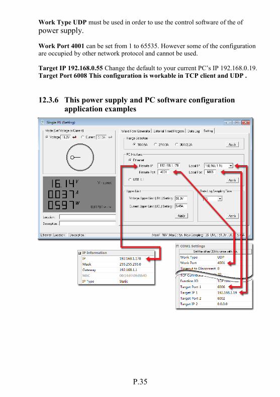
Work Type UDP must be used in order to use the control software of the of
power supply. Work Port 4001 can be set from 1 to 65535. However some of the configuration are occupied by other network protocol and cannot be used. Target IP 192.168.0.55 Change the default to your current PC’s IP 192.168.0.19. Target Port 6008 This configuration is workable in TCP client and UDP .
12.3.6 This power supply and PC software configuration application examples
P.34 P.35
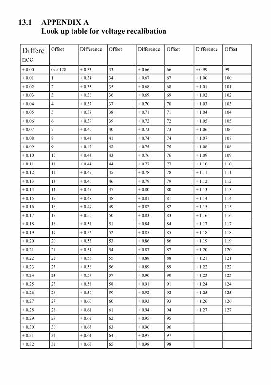
13.1 APPENDIX A Look up table for voltage recalibation
Difference
Offset Difference Offset Difference Offset Difference Offset
+ 0.00 0 or 128 + 0.33 33 + 0.66 66 + 0.99 99
+ 0.01 1 + 0.34 34 + 0.67 67 + 1.00 100
+ 0.02 2 + 0.35 35 + 0.68 68 + 1.01 101
+ 0.03 3 + 0.36 36 + 0.69 69 + 1.02 102
+ 0.04 4 + 0.37 37 + 0.70 70 + 1.03 103
+ 0.05 5 + 0.38 38 + 0.71 71 + 1.04 104
+ 0.06 6 + 0.39 39 + 0.72 72 + 1.05 105
+ 0.07 7 + 0.40 40 + 0.73 73 + 1.06 106
+ 0.08 8 + 0.41 41 + 0.74 74 + 1.07 107
+ 0.09 9 + 0.42 42 + 0.75 75 + 1.08 108
+ 0.10 10 + 0.43 43 + 0.76 76 + 1.09 109
+ 0.11 11 + 0.44 44 + 0.77 77 + 1.10 110
+ 0.12 12 + 0.45 45 + 0.78 78 + 1.11 111
+ 0.13 13 + 0.46 46 + 0.79 79 + 1.12 112
+ 0.14 14 + 0.47 47 + 0.80 80 + 1.13 113
+ 0.15 15 + 0.48 48 + 0.81 81 + 1.14 114
+ 0.16 16 + 0.49 49 + 0.82 82 + 1.15 115
+ 0.17 17 + 0.50 50 + 0.83 83 + 1.16 116
+ 0.18 18 + 0.51 51 + 0.84 84 + 1.17 117
+ 0.19 19 + 0.52 52 + 0.85 85 + 1.18 118
+ 0.20 20 + 0.53 53 + 0.86 86 + 1.19 119
+ 0.21 21 + 0.54 54 + 0.87 87 + 1.20 120
+ 0.22 22 + 0.55 55 + 0.88 88 + 1.21 121
+ 0.23 23 + 0.56 56 + 0.89 89 + 1.22 122
+ 0.24 24 + 0.57 57 + 0.90 90 + 1.23 123
+ 0.25 25 + 0.58 58 + 0.91 91 + 1.24 124
+ 0.26 26 + 0.59 59 + 0.92 92 + 1.25 125
+ 0.27 27 + 0.60 60 + 0.93 93 + 1.26 126
+ 0.28 28 + 0.61 61 + 0.94 94 + 1.27 127
+ 0.29 29 + 0.62 62 + 0.95 95
+ 0.30 30 + 0.63 63 + 0.96 96
+ 0.31 31 + 0.64 64 + 0.97 97
+ 0.32 32 + 0.65 65 + 0.98 98

APPENDIX A (Continued) Look up table for voltage recalibation (Continued)
Difference
Offset Difference Offset Difference Offset Difference Offset
- 0.01 129 - 0.34 162 - 0.67 195 - 1.00 228
- 0.02 130 - 0.35 163 - 0.68 196 - 1.01 229
- 0.03 131 - 0.36 164 - 0.69 197 - 1.02 230
- 0.04 132 - 0.37 165 - 0.70 198 - 1.03 231
- 0.05 133 - 0.38 166 - 0.71 199 - 1.04 232
- 0.06 134 - 0.39 167 - 0.72 200 - 1.05 233
- 0.07 135 - 0.40 168 - 0.73 201 - 1.06 234
- 0.08 136 - 0.41 169 - 0.74 202 - 1.07 235
- 0.09 137 - 0.42 170 - 0.75 203 - 1.08 236
- 0.10 138 - 0.43 171 - 0.76 204 - 1.09 237
- 0.11 139 - 0.44 172 - 0.77 205 - 1.10 238
- 0.12 140 - 0.45 173 - 0.78 206 - 1.11 239
- 0.13 141 - 0.46 174 - 0.79 207 - 1.12 240
- 0.14 142 - 0.47 175 - 0.80 208 - 1.13 241
- 0.15 143 - 0.48 176 - 0.81 209 - 1.14 242
- 0.16 144 - 0.49 177 - 0.82 210 - 1.15 243
- 0.17 145 - 0.50 178 - 0.83 211 - 1.16 244
- 0.18 146 - 0.51 179 - 0.84 212 - 1.17 245
- 0.19 147 - 0.52 180 - 0.85 213 - 1.18 246
- 0.20 148 - 0.53 181 - 0.86 214 - 1.19 247
- 0.21 149 - 0.54 182 - 0.87 215 - 1.20 248
- 0.22 150 - 0.55 183 - 0.88 216 - 1.21 249
- 0.23 151 - 0.56 184 - 0.89 217 - 1.22 250
- 0.24 152 - 0.57 185 - 0.90 218 - 1.23 251
- 0.25 153 - 0.58 186 - 0.91 219 - 1.24 252
- 0.26 154 - 0.59 187 - 0.92 220 - 1.25 253
- 0.27 155 - 0.60 188 - 0.93 221 - 1.26 254
- 0.28 156 - 0.61 189 - 0.94 222 - 1.27 255
- 0.29 157 - 0.62 190 - 0.95 223
- 0.30 158 - 0.63 191 - 0.96 224
- 0.31 159 - 0.64 192 - 0.97 225
- 0.32 160 - 0.65 193 - 0.98 226
- 0.33 161 - 0.66 194 - 0.99 227
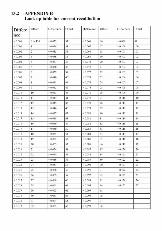
13.2 APPENDIX B Look up table for current recalibation
Difference
Offset Difference Offset Difference Offset Difference Offset
+ 0.000 0 or 128 + 0.033 33 + 0.066 66 + 0.099 99
+ 0.001 1 + 0.034 34 + 0.067 67 + 0.100 100
+ 0.002 2 + 0.035 35 + 0.068 68 + 0.101 101
+ 0.003 3 + 0.036 36 + 0.069 69 + 0.102 102
+ 0.004 4 + 0.037 37 + 0.070 70 + 0.103 103
+ 0.005 5 + 0.038 38 + 0.071 71 + 0.104 104
+ 0.006 6 + 0.039 39 + 0.072 72 + 0.105 105
+ 0.007 7 + 0.040 40 + 0.073 73 + 0.106 106
+ 0.008 8 + 0.041 41 + 0.074 74 + 0.107 107
+ 0.009 9 + 0.042 42 + 0.075 75 + 0.108 108
+ 0.010 10 + 0.043 43 + 0.076 76 + 0.109 109
+ 0.011 11 + 0.044 44 + 0.077 77 + 0.110 110
+ 0.012 12 + 0.045 45 + 0.078 78 + 0.111 111
+ 0.013 13 + 0.046 46 + 0.079 79 + 0.112 112
+ 0.014 14 + 0.047 47 + 0.080 80 + 0.113 113
+ 0.015 15 + 0.048 48 + 0.081 81 + 0.114 114
+ 0.016 16 + 0.049 49 + 0.082 82 + 0.115 115
+ 0.017 17 + 0.050 50 + 0.083 83 + 0.116 116
+ 0.018 18 + 0.051 51 + 0.084 84 + 0.117 117
+ 0.019 19 + 0.052 52 + 0.085 85 + 0.118 118
+ 0.020 20 + 0.053 53 + 0.086 86 + 0.119 119
+ 0.021 21 + 0.054 54 + 0.087 87 + 0.120 120
+ 0.022 22 + 0.055 55 + 0.088 88 + 0.121 121
+ 0.023 23 + 0.056 56 + 0.089 89 + 0.122 122
+ 0.024 24 + 0.057 57 + 0.090 90 + 0.123 123
+ 0.025 25 + 0.058 58 + 0.091 91 + 0.124 124
+ 0.026 26 + 0.059 59 + 0.092 92 + 0.125 125
+ 0.027 27 + 0.060 60 + 0.093 93 + 0.126 126
+ 0.028 28 + 0.061 61 + 0.094 94 + 0.127 127
+ 0.029 29 + 0.062 62 + 0.095 95
+ 0.030 30 + 0.063 63 + 0.096 96
+ 0.031 31 + 0.064 64 + 0.097 97
+ 0.032 32 + 0.065 65 + 0.098 98

APPENDIX B (Continued) Look up table for current recalibation (Continued)
- 0.015 143 - 0.048 176 - 0.081 209 - 0.114 242
- 0.016 144 - 0.049 177 - 0.082 210 - 0.115 243
- 0.017 145 - 0.050 178 - 0.083 211 - 0.116 244
- 0.018 146 - 0.051 179 - 0.084 212 - 0.117 245
- 0.019 147 - 0.052 180 - 0.085 213 - 0.118 246
- 0.020 148 - 0.053 181 - 0.086 214 - 0.119 247
- 0.021 149 - 0.054 182 - 0.087 215 - 0.120 248
- 0.022 150 - 0.055 183 - 0.088 216 - 0.121 249
- 0.023 151 - 0.056 184 - 0.089 217 - 0.122 250
- 0.024 152 - 0.057 185 - 0.090 218 - 0.123 251
- 0.025 153 - 0.058 186 - 0.091 219 - 0.124 252
- 0.026 154 - 0.059 187 - 0.092 220 - 0.125 253
- 0.027 155 - 0.060 188 - 0.093 221 - 0.126 254
- 0.028 156 - 0.061 189 - 0.094 222 - 0.127 255
- 0.029 157 - 0.062 190 - 0.095 223
- 0.030 158 - 0.063 191 - 0.096 224
- 0.031 159 - 0.064 192 - 0.097 225
- 0.032 160 - 0.065 193 - 0.098 226
- 0.033 161 - 0.066 194 - 0.099 227
P.39

13.3 APPENDIX C Command set of the SSP-8080
Command Code Description
SOUT <OFF> <CR> [OK] [CR]
Set Output On/Off
GOUT <CR> Output [?] [CR] [OK] [CR]
Get Output Status
GOVP <CR> Voltage [???] [CR] [OK] [CR]
Get UVL Setting Value
SETD Abc{0-2} Voltage{????} Current{????} <CR> [OK] [CR]
SET Voltage and Current
GOCP <CR> Current [???] [CR] [OK] [CR]
Get UCL Setting Value
SOVP Voltage {????} <CR> [OK] [CR]
Set UVL Value
SOCP Current [????]<CR> [OK] [CR]
Set UCL Value
GETD <CR> Voltage [????] Current [????] [0] [CR] [OK] [CR] Voltage [????] Current [????] [1] [CR] [OK] [CR]
Get Reading Volt & Current CV Mode CC Mode
GETS Abc {0-2} <CR> Voltage [????] Current [????] [CR] [OK] [CR]
Get Setting Volt & Current
VOLT Abc {0-2} Voltage {????}<CR> [OK] [CR]
SET Output Voltage Value
CURR Abc {0-2} Current {????}<CR> [OK] [CR]
SET Output Current Value
GABC <CR> ABC {0-2} [CR] [OK] [CR]
Get ABC Selection
SABC Abc {0-2} <CR> [OK] [CR]
Set ABC Selection
GCHA <CR> Range [0-2][CR] [OK] [CR]
Get Range Selection

SCHA Range {0-2} <CR> [OK] [CR]
Set Range Selection
SESS <CR> [OK] [CR]
Disable Keyboard
ENDS <CR> [OK] [CR]
Enable Keyboard
GDLT location {0-5}<CR> delta time [00-20] [CR] [OK] [CR]
Get Delta Time Setting Value
SDLT location {0-5} time {00-20} <CR> [OK] [CR]
Set Delta Time
GSWT location {0-2} <CR> sw time [000-600] [CR] [OK] [CR]
Get SW Time
SSWT location {0-2} time {000-600} <CR> [OK] [CR]
Set SW Time
RUNP first {0-2} end {0-2} <CR> [OK] [CR]
Run SW
STOP <CR> [OK] [CR]
Stop SW Running
GEEP location {0-3}<CR> location 00 [000-255] location 01 [000-255] . . . . location 15 {000-255} [CR] [OK] [CR]
Get EEPROM Data
SEEP location {0-3} location 00 {00-FF} location 01 {00-FF} . . . location 15 {00-FF} <CR> [OK] [CR]
Set EEPROM Data (Hex Data Format)
Note: Output [ON] on = 31h, [OFF] = 30h

13.4 APPENDIX D - Operation Mode Description
Working Mode Description
TCP Server TCP Client
When using TCP, connection must be established before transferring data. TCP Server waits for the client to connect, while TCP Client actively connects the destination IP and destination port. Two Ethernet card modules can therefore work to communicate with one being a TCP Server; while the second one should be setup as a TCP Client to receive and transmit.
UDP UDP mode does not setup the connection, so if UDP is used to transmit data, it only transmit and receive data from the specified destination IP and destination port. If there are more than one network components connected to the Ethernet card module, then the TCP should be first setup to establish the connection. Afterwards, the connection should be closed so that the other network components can connect the Ethernet card module. Note: Since UDP does not have the maximum packet limit, the Ethernet card module is set to have valid frame with a maximum of 560 bytes, the packet might be lost if more characters are used.
RealCOM RealCOM Mode is the virtual serial ports working mode.
Group Mode Group Mode is a working mode with multicast. Under group mode, the Ethernet card modules that have the same multicast ID and ports will share the network data, i.e. the Ethernet data from one module is received by others and changed to serial communication.
TCP Auto Mode TCP Auto mode is an automatic TCP working mode. If the serial ports have not received the data, the Ethernet card module will work as a server and listening to the working ports, waiting for the clients to connect. If the Ethernet card module can receive the data, then the Ethernet card module will automatically establish connection with destination IP and destination ports, and then transmit the data.

13.5 APPENDIX F List of default ports that are assigned by TCP and UDP Protocol Port
Reserved 0
TCP Port Service Multiplexer 1
Management Utility 2
ECHO 7
Reserved 9
Reserved 11
Reserved 13
Netstat 15
FTP 20
FTP 21
TELNET 23
SMTP 25
Printer 35
Time Server 37
Host Name Server 42
Reserved 43
Login Host Protocol (TACACS) 49
DNS 53
DHCP 67
DHCP 68
TFTP 69
Gopher 70
Finger 79
HTTP 80
Remote TELNET 107
SUN Remote Procedure Call 111
Network News Transfer Protocol 119
Network Time Protocol 123
SNMP 161
SNMPTRAP 162
IPX 213
Reserved 160-223
13.6 APPENDIX G - IPORT-1 module speed test result
Protocol Transmission
Direction Baud rate Description
TCP Serial to Ethernet <19200bps No delay
>38400bps Continuously sending 512 bytes with a period 230ms
Ethernet to Serial Free TCP has flow control, maximum baud rate 115200, speed was 10.6KB/s
UDP Serial to Ethernet <115200bps No delay
Ethernet to Serial 9600bps Continuously sending 512 bytes with a period >500ms
19200bps Continuously sending 512 bytes with a period >250ms
57600bps Continuously sending 512 bytes with a period >100ms
115200bps Continuously sending 512 bytes with a period >80ms