Embed Size (px)
Citation preview

FOR AMATEUR RADIO DESIGNERS AND BUILDERS
SPRING

E E C'TR.CM•TI C ]KrTS
Everybody who owns a shortwave receiver may already have tried to decode those mysterious morse messages...
Morse Decoder
Kit
$109.95 This decoder easily keeps up with the quickest signallers, and neatly" notes" everything on a display. You can Fosi y read all messages, even if you are not familiar with morse cif-all! Alphanumeric LC-di ay * 1 line of 16 characters * Power supphy: 2x7 to 8 VAC/150 mA or 9 -12VDC/100mA*PCE dimensions: 70x115mm.
K1771 FM Transmitter $16.95 K2032 Digital Panel
f flOàle» 0 — r 3
cs(4 r ke E 0.4ie•Etaa E
C2,
"ruit
TUNING
Mini FM transmitter (100-108 Ml-tz). Integrated e - amplifier ( sensitivity 5 mV I, to \Ake any t'pec miŒophor1e may be connected. Power supply: 9 -12 VDC
K2622 Antenna Amp
$39.95
Power sjppl. 5VDC, 250 mA I regulated) * Read out: -999 mV to + 99 mV, lmV resolution • Overload indication (positive and negafive) * Linearity 0.19,'D " Input impedanœ 100 mohm.
$15.95 K2651 LCD Panel $39.95
Do away with noisy signals! The K2622 gives you 22dB gain vvhere it's needed. DC supply direct or via the coax cable (50-75 Ohm imped-ancel, metal box induded.
ORDER INFORMATION
PAYMENT METHODS - Visa - Mastercard - Check
$5 00 Shipping charge per order. No COD.
This kit provides an easy-b-read display. Be-cause of the simple power supply require-ment and compadeze of the IC, Icon easily be incorperated into a variety of applioptions.
dl.Ei CALL: (303)-480-7544 r FAX : (303)-480-7552
1-800-453-2919 \\ MI Mail: Tapto Corporation IP—....11111031 2650 18th Street
Denver, CO 80211

• Contents •
Letters 4 Kit Review: OHR WM-1 QRP Wattmeter, George Franklin, WOAV 7 An Easy To Build 15 Watt Transmitter, Lew Smith N7KSB 9 New Products 15 Brand New MXM Transceiver 16 Some Tips On VFO Stability, Doug DeMaw W1FB 19 Neophyte Roundup 22 The W6EMT 10 Meter Receiver, Roy Gregson, W6EMT
Improved Neophyte Receiver, Wes Baden, K6EIL 25 23
Using Transistors and ICs, Bruce Williams, WA6IVC 28 20/20 Hindsight 30 TwoFer III Salvation Transmitter, John Christopher, NG'7D 32
Narrow Band Sweep For Signal Generators, John Pivnichny, N2DCH 38
Shack Shots 45 Classified Advertising 46
Photographic Credits: Front Cover, p. 25: K6EIL; p.7: Oak Hills Research; Inside back cover, p. 9: N7KSB; p. 19: WI FB; pp. 34, 35, 36, 37: NG7D; pp. 38, 39, 40, 42, 43: N2DCH; p. 45: W8MVN
hambrew COPYRIGHT 1994, Smoking Pencil & Co.
All Rights Reserved
FOR AMATEUR RADIO DESIGNERS AND BUILDERS
SPRING, 1994 • VOL 2, NO.2
Publisher George De Grazio, WFOK
Writers, Editors and Contributors:
George Franklin, WOAV; Bruce O. Williams, WA61VC; Doug DeMaw, W1FB; Lew Smith, N7KSB; Roy Gregson, W6EMT; Wes Baden, K6EIL; Dick Pattinson, VE7GC;
John Christopher, NG7D; John Pivrtichny, N2DCH; Ernie Helton, W8MVN
Ads & Subscriptions: 1-800-5-HAM RIG • Editorial Office: (303) 989-5642
Hambrew is published quarterly by Smoking Pencil & Co., Publishers, Offices at 13562 West
Dakota Ave., Lakewood, Colorado 80228. Application to Mail at Second-Class Postage Rates is Pending at Denver, Colorado. POSTMASTER: Send address changes to
Hambrew, P.O. Box 260083, Lakewood, CO 80226-0083. Hambrew is sold by subscription only.
$20 per year (domestic), $35 (foreign), $25 (Canada and Mexico) We welcome submission of articles, photos and manuscripts (S.A.S.E. for return)
1111111111 3
11111111110,1111 IIMIld11111.111fill11111111110,

• LETTERS •
From The Publisher
I think you will like this issue! We were
greatly pleased with the contributions last issue of all involved, of course our stalwart yeomen Larry Feick, NFOZ and Bill Mason, NOKEP, and most notably the input from Bruce Williams, WA6IVC and Fred Bonavita, W5QJM, both of whom enjoy no small stature in our hobby, and are widely published and recognized. We thank also Bill Todd, N7MFB, the NWQRP Club President, always a staunch backer of Hambrew, both in contributions and philosophical support We are grateful, Bill.
This issue debuts our first article from one who needs no introduction, having achieved a longstanding preeminence among builders who publish: Dong DeMaw, W1FB. We hope to spotlight future articles by Doug, who continues to inspire and influence both first-time and OT builders worldwide. We value his ongoing contributions to the hobby and this publication.
Bruce Williams continues his series on QRP Design and Construction with a valuable
and useful section on transistors and ICs. This series should appeal to those of us who devour information which relates to the practical side of the construction/design process. The Rig-O-Rama contest continues to draw
responses from readers, and we present two rigs in this issue, both interesting in design and purpose: Lew Smith, N7KSB debuts an unusual and interesting 5/15 watt 15 Meter rig in which you will find a fresh approach to oscillation. It is modifiable to other bands as well. John Cristopher, NG7D has offered a modified TwoFer transmitter for 40m which we like very much. He has much improved the design with not only a sidetone oscillator, but
a nifty variable power output control and a beefed-up final filter section. On a somber note: we regret to report the
passing of Wes Farnsworth, KEON11, who
became a silent key February 8, 1994. Wes
was with us at the nativity of Hambrew; he loved the magazine and the idea of its purpose.
He contributed to the first issue, and continued to provide ideas for future articles. His cheerful optimism and prolific outpouring of ideas and creativity in the face of his own personal medical situation give all who knew him an example of courage which we will carry for the rest of our lives. He will be missed. Elsewhere in Spring, '94: John Pivnichny,
N2DCH has a great article on adding narrow band sweep to your signal generator. Wes Baden, K6EIL, lays out a very nice-looking Improved Neophyte Receiver which is very impressive indeed (see page 26), and a designer in Washington state, Roy Gregson, W6EMT, shows us a keen 10 meter varactor-tuned receiver based loosely on the Neophyte
prototype. Roy will reappear in the Summer Issue with an 80 meter transmitter which has a VXO that has an extra-wide frequency-swing capability - interesting! As usual, we welcome our new subscribers - glad to have you with us and do keep spreading the good word! Dear Hambrew,
I was very pleased with my sample issue of "Hambrew" (Autumn, '93)... I'm a neophyte and would appreciate 1 or 2 articles in each issue aimed at Home Brewers at this level. I really feel that "Hambrew" can serve a particular segment of the hobbyist population very well. Keep up the good work & good luck! Morton Goodman New York, NY Thanks Morton! We try in each issue to
provide something for each level of experi-ence. And for the information of our regular subscribers, we do not provide sample or back issues on a speculative basis. We feel (and some subscribers have mentioned this) that it
devalues the investment made by our subscrib-ers. We value your importance to our sur-vival! And we welcome Morton to the fold!
4

Hambrew Magazine Dear George-
Received your ...first issue the other day. At first $20 for four issues seemed a little steep,
but on reflection and consideration it becomes apparent that your magazine is a bargain. Four concise contruction articles alone would work
out to $1.25 per article. But considering the many more construction articles it is indeed a bargain.
J.P. Isom, KA7KOI Halsey, OR
And we hope that we are getting better each issue, JP! This issue alone has more projects than any single one previously published by
us, and we work always for a higher "Q"!
Dear Hambrew
The last few weeks of Ramsey remodeling have been great. On the air, and on the work bench!
My larPst project was a TWO BAND RAMSEY 15/17 Meter Transmitter. This was so simple I'm waiting for the TRAIN WRECK! One socket has a 21.120 crystal and the other 18.090 MHz. The seven element 15 meter output filter takes care of harmonics above 21.4 MHz Can it really be this simple? Operating a Two Bander Ramsey is really a blast! The JAN crystals cover about 12 KHz
on 17, and 16 KHz on 15 meters. This is NOT like 30 or 40 M with only 3 or 4 KFlz of swing. This rig is a mal joy to build and operate!
Next I want to cover all of 15 meters, and that means crystal switching or a VFO. A new RF probe confirms power output of 1
watt for the 15 meter transmitter with 2SC1017, and the same for the 17 meter rig with a 2N3866 (NPN VHF/UHF AM).
The TO-39 2N3866 works very well when going for higher frequency bands like 15 and 17 meters. It replaces Q3 like the stock
transistor, and is fairly cheap. The TO-220
style transistor must be adapted to the board, and the BCE holes enlarged. If using this style,
cross the C and B legs; the printed side faces the rear of the board.
Another option is the NTE299 (Hambrew #1 Ramsey 30M). This is a TO-202 style transistor, and the three legs are set up CBE so
it's a better fit once you enlarge the holes on the board. It didn't have the power when asked to work on 15/17.
An overall winner is the 2N3866 at this stage of the game. And in this hobby if someone finds a cheaper and easier to get final for 15/17
meters we all win! This may also be better than the stock 2N3053 if you actually use your Ramsey QRP-20 on 20 meters, Hi Hi! My little Ramseys are tucked away in nice
Radio Shack metal cases with knobs now, and looking pretty good!
I've worked Hawaii, France, South & Central America, Antarctica, Hungary, The Bahamas,
Cuba and Alaska with my ONE watt Two Bander Ramsey! If you hear me on the air, you might notice a minor frequency variation. I'm
(lacking) $30,000 (to install) power poles and running on batteries. The battery voltage can change some if a cloud passes by and the solar array is eclipsed! Jim Hale, KJ5TF (Tired Fingers) Kingston, AR
(More Letters, Page 6)
Egg-On-Face Dept.
Yes, the Pipsqueak Xmtr, due to a rushed and late insertion into the Winter Issue, had some incorrect values and a missing
component The little guy is out of the hospital, and will be shown in the Summer Issue with a brand-new
working power amp and an adjustable power output of a heady 600mw!
Don't miss the new Pipsqueak X-1-Coming Soon in Hambrew!
5

(More Letters)
Sir. Just wanted to let U know I have seen a copy of your wonderful magazine. Unfortunately, I can't afford $20/yr for a quarterly publication! I know printing costs are high for any magazine at start-up. Just know that some of us out there would love to subscribe, if our pockets were deeper! Philip Corlis, KB70PD Coeur d'Alene, ID
Dear Philip:
Just a quick note to thank you for the nice QSL card and complimentary words about our magazine. I appreciate your comments!
You are absolutely right about the high costs ofp rinting a quality magazine, and the costs do not go down with longevity. I do get a fair share of comments about the cost of subscrip-tion, and we are inundated with requests for (free) sample copies. We did give away 3000 copies of our inaugural run, and we gave our paying subscribers a free issue to be equi-table. Naturally, ewe behave this way all the time, we will be known as the "great philan-thropists" of the ham publishing world, but it simply will not pay our bills. Unfortunately, our very high-quality printer does not give out sample press runs and sample expensive pa-per in 23" X 35" sheets. The post office does not give us sample shipping and postage, and the phone company does not give sample months of 800 number usage.
I know you understand all this, but it helps to get it off of my chest! As to the price of Hambrew...let's put it into perspective. The Spring Issue will have two transmitter sche-
matics, two receiver schematics and a circuit for adding an S meter to DC receivers, among other articles. What would be the price of each project plan? Less than a dollar. Add in free classifieds to subscribers, commercial or non-commercial, and you are getting some bang for the buck.
I have a copy of an amateur radio news maga-zine in front of me. It costs $2 per issue. It is 32 pages in length and has the equivalent of 16 pages of advertising. It is now down to 50% of actual informational content. There is one project outline for an antenna preamplifier. Conunercial classeeds are .80/word. It is printed on newsprint.
There are some great QRP Clubs out there (I'm a member of several) - and I enjoy getting their publications, which generally have no photographs and are not magazine-quality. For this, I am happy to pay $10/yr.- and I get a membership number.
Don't get me wrong, I have nothing against other magazines or QRPIRadio Clubs. I'm just trying to make a practical comparison. The cost of one Szechuan Chinese dinner, consisting of one plate of chicken in garlic sauce, one plate of Mongolian beef one large bowl of rice, two bowls ofs weet and sour soup, two eggrolls and a pot of tea costs $26 includ-ing a $2.50 tip. If it takes 26 minutes to enjoy the meal, that's $1/minute. Hambrew lasts a lot longer, but I must confess does not taste nearly as good (or so they tell me).
I know all of this doesn't make anyone's pock-ets deeper, but know that Hambrew is a real player: we are in it for the duration, God willing, and we will be around when you have the wherewithal to make the investment. Thanks again, Philip, for the card and comments, and thanks for hearing this litany of my concerns.
Back Issues of liamtbree: To keep your Hambrew collection complete, we still have a number of back issues
available. Our Inaugural Issue was Autumn, '93. We're told it's already a collector's item. Back issues are $6/each, mailed in an envelope via first class mail. Supplies are limited.
6

KIT REVIE W
Oak Hills Research QRP Wattmeter George Franklin, WOAV
4417 N. Elmwood Avenue, Kansas City, MO 64117
As an old-timer in the world of QRP operation, I have always had a bit of a problem in determining with any degree of accuracy the RF power output of a particular QRP rig. Oak
Hills Research has solved this prob-lem nicely and rather economically
with their excellent Model WM-1 QRP HF Wattmeter kit When I read the ad for the WM-1
in one of the ham mags, I had no reservations about ordering one, based on previous very satisfactory experiencewith the OHR 40M QRP CW transceiver kit. Dick, the main man at OHR, informed me that WM-l's were selling like the proverbial hotcakes, but that mine would be shipped in a week or so, pending arrival of the metal enclosures from his supplier. True to his word, the kit arrived promptly, in time for my QRP Show and Tell at the recent KC hamfest
The WM- 1 is not only a QRP wattmeter, but a forward/reflected (VSWR) meter as well,
with scales of 10W, 1W and 100mW! The attractive unit measures approximately 4 X 4
X 6 inches, with a large, easy-to-read panel meter and two switches on the front panel.
Two SO-239 jacks adorn the rear panel for connections to the transceiver and load.
The circuit consists of a directional coupler utilizing two prewound toroids plus two IC's. It is powered by an internal 9V transistor
battery which should last for many months, since the drain is only 1.2 mA.
Assembly is easy, straightforward and fun
for anyone who likes building kits. Calibra-tion is extremely simple, requiring only a few adjustments using a low-cost digital voltme-ter. After calibration of each scale is accom-plished, snipping a jumper readies the WM-1 for service. No accuracy specification is pro-vided, however comparison of the WM-1's
reading on quality two-way radio test equip-ment showed no meaningful discrepancies whatsoever in the HF range.
The assembly manual, while not quite up to "Heathkit standards", is entirely adequate. It includes basic component identification infor-
mation in addition to a parts list, component layout, PCB drawing (Continued on page 8)
7

(Continued from page 7)
Calibrating the OHR WM-1 is a snap! A digital voltmeter is required.
schematic diagram and other useful informa-tion. A simple Operation section is included, although the well-labeled front panel controls leave no doubts in that respect. The unit carries a one-year limited warranty, including the usual outstanding Oak Hills personal tech-nical support by phone (616) 796-0920. Once again, OHR has done an excellent job
in meeting QRPer's need for good, simple, low-cost equipment Their new Spirit QRP transceiver (see magazine ads or call Dick at OHR for further information) promises to be another QRP winner. • • •
WM-1 QRP Wattmeter: $89.95
Available from Oak Hills Research 20879 Madison Street Big Rapids, MI 49307 Orders: (800) 842-3748
We've Upgraded!
Notice a d«erence this issue? Henceforth, subscriber issues of Hambrew will be protected in plastic for the journey from here to you. We have applied for and are currently mailing via second class to provide faster and safer service to you. As articles increase, look for more pages in each issue - the long-term goal is to go
bimonthly - at the same price. We're growing, thanks to you!
8

Itg 0 ama
An Easy To Build 15 Watt Transmitter
Lew Smith, N7KSB 4176 N. Soldier Trail, Tucson, AZ 85749
Here is an easily constructed, low cost 15 watt transmitter that can be built first as a 15 meter novice rig and later modified for 15, 17 and 20 meter triband operation. A combina-tion of four inexpensive (just over $3 total) semiconductors results in a simple yet clean-sounding rig. Construction has been simpli-fied by eliminating the usual metal chassis, metal heat sinks, etched boards and toroid transformers.
The circuit (figure 1) uses a 74HC240 octal inverting buffer logic IC for both oscillator and driver functions. One of the eight invert-ers is used as a Colpitts crystal oscillator. The
other seven inverters are wired in parallel to operate as a driver for the final. The 74HC7A0 is operated somewhat above maximum rating to squeeze out as much power as possible.
The final is a low-cost IRF510 power MOSFET. It is driven fairly hard to obtain more output than expected from straight class
B operation.
The circuit in figure 1 uses a 15 meter (only) filter that transforms the 25 ohm MOSFET impedance to 50 ohms at the an-tenna terminal. A triband modification will be described later. A 7.5 volt regulator and a Darlington PNP
keying transistor complete the circuit. I chose to build all the circuitry on the top
surface of a 2" x 8" x 6" (H x W x D) box. This top surface is a 1/16" thick double-sided PCB that serves as a combination front panel, heat sink and ground plane. Fiberglass PCB mate-rial is rigid enough for the job, yet extremely easy to cut, drill and file.
The rest of the box is a combination of 1" x 2" wood and PCB material. I used wood for the right and left sides, and PCB for the rest. The top, bottom, front and rear sides are fas-tened to the wood using screws. By removing four top (Continued on page 10)
9

Continued from page 9)
ROTOR Fundamental \864.35 PF Mode xtal
0
C(a) C(b RI
330n I 33 9F 33PF 1 —
—
U2*
Figure 1
* Heat Sink (see text)
ç \ N7KSB 15 Meter
4/15 Watt Transmitter }
0.1
Cl, C4 150pF (mica) L2, L3, L4 6 Turns, 1/21ong, C2 620pF (mica) #14 to #18, 3/8" C3 300pF (mica) ID (see text) C(a), C(b) 33pF (ceramic) RFC1 25 Tunis, close-
05, C6 2.2/4F (tantalum) wound, #18 to #24 C7, 8,9 0.1/4F (ceramic) 3/8" ID (see text) C10 0.1µF (cer. disk) SlA, S1B 1 amp DPDT SW. Q1 TIP115 Ul 74HC240 (see text) Q2 IRF510 U2 LM317T
10
(Continued from page 10) side screws, the electronics can be removed for servicing. Aluminum foil should be glued to the inside and all mating wood surfaces to allow good shielding. Ground plane (or "ugly") construction is
recommended. RF leads, especially the MOSI-EI leads, should be kept short. Try to
drill the tuning capacitor and T/R switch holes 5" apart to allow enough room for all the RF components.
The 74HC240 is epoxied upsidedown to the main front panel PCB. This heatsitiks the part. Remember to mark pin one on the bottom before applying epoxy. Also note that IC pin numbers go clockwise when viewed from the bottom.
The other three semiconductors are heat sunk by using three 1" x 1" pieces of 1/16" PCB material as heatsink insulators. The 1" x 1" pieces are epoxied to the main PCB and then the metal tabs of the semiconductor packages soldered on top (see figure 2a).
Most parts are readily available from local
sources and/or mail order houses. However, the variable capacitor may require some shopping. Although a 35pF variable capacitor was used in this circuit, I have successfully used a 20pF and also a 70pF capacitor in similar designs. A plastic-foil style 70pF tuning capacitor cannibalized from a pocket AM radio will work well. If all else fails, use
a trimmer capacitor until something better is found.
Shield the variable capacitor and the crystal socket from the final amplifier by using a piece of PCB material. Since the rotor of the capacitor is ungrounded, a 1" or larger plastic knob should be used to minimize hand capacitance effects.
Full power operation requires a one amp 24 volt supply. The simple unregulated (but well filtered) 22 volt supply shown in figure 3 works well. For QRP work, a 12 to 14 volt supply will give an RF output of approximately 4 watts.
Upsidedown 74HC240 Epoxy to PCB Front Panel
IRF510, LM317T and TIP115 mounted on 3 separate 1" x 1"
Solder center lead to top of 1" x 1" PCB heatsink insulator 11. -
PCB heatsink insulators Solder to 1" x 1" PCB
Epoxy 1" x 1" PCB to Bfront panel
Figure 2a
The self-supporting ("airwound") coils are wound on a 3/8" mandrel ( a 3/8" rod, dowel or the chuck end of a 3/8" drill bit will do). An attempt should be made to mount adjacent coils at right angles to prevent unwanted coupling.
Debugging is straightforward if the 74HC240 is temporarily disconnected from
the LM317T. Also temporarily short the MOSFET gate to ground and solder a 10k resistor from the TIP115 collector to ground.
Now apply power (Continued on page 12)
11

(Continued from page 11) and check the LM317F output for roughly 7.5 volts. Check the TIP115 collector voltage: key up should be near zero and key down should be near the supply voltage. Also check to see if the T/R switch disconnects the receiver from the antenna in the transmit position. Now reconnect the 74HC240 and remove the gate short and the 10k resistor. Next, check out the oscillator. To prevent
MOSFEI damage, be careful not to key the transmitter until the oscillator is working. Check for reliable oscillator starting (decrease
Cb if necessary). Also watch for excessive frequency drift in the first 30 seconds (increase Ca if necessary).
Add a dummy load and check for key down output power. If a power meter or RF voltmeter
is not available, output can be estimated by calculating 2/3 of the input power. Expect
about 12 watts on 15 meters and , in the triband version, 18 watts on 20 meters when using the 22 volt supply shown in figure 3. Power is a very sensitive function of the
LM317T output voltage. If low regulator
voltage is causing a problem, it can be raised 1/2 volt by adding a 2.2k resistor in parallel with the 200 ohm resistor connected to the LM317T adjust and output pins. Other low output (or no output) problems
may require probing with an RF voltmeter to determine whether the MOSFET, the filter, the seven inverters or the T/R switch is at fault Once the transmitter has been debugged, it is ready to put on the air.(Continued next page)
IRF510 G ID S
TIP115 B C E
LM317T adjoutin
12

The tuning capacitor allows about an 11 kHz range on 15 meters. This can be increased to roughly 30 kHz by inserting a coil between the tuning capacitor and the crystal. Approximately 30 turns of #30 wire closewound on a 3/8" plastic rod are needed. The exact number of turns must be determined experimentally. If too many turns are used, frequency stability will become very poor. Triband (15, 17 and 20 meters) operation is
possible if the 25 to 50 ohm transformation feature is removed from the filter and performed with external coax networks as shown in figure 4. A separate coax network is needed for each band. In addition to transforming the output to
50 ohms, the 1/8 wavelength section attenuates the second harmonic by an additional 30dB. Note: Do not use the extra coax sections if
the transmitter has been built as a single band 15 meter rig using the values of C3 and C4 given in figure 1. Ten meter operation was tested but never
put on the air. The following ten meter circuit
values should work, but there may still be a
120V AC
18V, 2A Transformer
2A 8ndge
I10,000pF
22VDC
A Simple Power Supply Figure 3
L2 L3 L4
Change C3 and C4 as shown
few bugs to iron out Expect 5 to 10 watts of output.
Change these parts for 10 meters:
R1 change to a 22pF cap. Ca 22pF Cb 10pF Cl 75pF C2 470pF
C3 220pF C4 100pF L2, L3, LA: 5 turns, 3/8" ID, 1/2"
long The ground plane construction technique
makes it easy to add extra circuitry. I added a
meter and a spotting position on the T/R switch in one version of this transmitter.
This transmitter has been fun to build and operate. This rig and a groundplane antenna are all I need for good DXing. • • •
• See additional photographs on inside back cover of this issue.
Coax Transformation Network Lengths Values for both solid and (foam coax) given
Band 1/10 X 1/8 X
15m 37" (45") 46" (56")
17m 43" (52") 54" (65")
20m 56" (68") 70" (84")
Add these coax sections Open
500 to ant.
Modifications For Tri band Operation
13
Figure 4

QUALITY KITS FROM 624 5 Watt QRP Transceiver Kit
Superhet Single Signal Receive Crystal LadderFilter Smooth AGC Semi Break-In Keying 12 Volt DC Operation
Built in AudioFilter Sidetone Oscillator Full 5 WattOutput
• Available on 15, 17, 20, 30, 40, 80 or 160 Meters Complete kit with Pre-Punched, Painted and Si&screen-ed Ten Tec enclosure, 40 page Instruction Manual and all parts including wire and hardware $153.00
Also available as a Semi-kit, with all PC Board parts and controls. You supply your own custom enclosure.
$115.00 Shipping $4.00 Complete Kit, $3.00 Semikit
Curtis 8044ABM Keyer Kit
Based on the new Curtis 8044ABM Chip, this keyer is a great addition to any rig. The PC board is 2" x 2" and will fit nicely into most Ql2P rigs. Power can be supplied by a stan-dard 9 volt battery or from your rig's power supply. The kit includes all parts, PC board and the 8044ABM chip with data sheet.
8044ABM Keyer Kit 831.00
8044ABM Chip and Data Sheet $17.50
W7EL QKP Wattmeter This kit is based on the excellent de-sign described in February 1990 Q,ST. It uses a unique microstrip line on the PC board and is accurate to 450 Mhz. It measures both power and SWR in 3 ranges: 10, 1 and .1 watt. Our kit includes th PC board and parts, all switches and controls and the battery connector. We also have available an LMB minibox and a nice meter as options. The kit uses a 9 Volt battery for power.
Wattmeter Kit $36.00 With Minibox $45.00
With Minibox and meter S53.00
Mini Circuits SBL-1 SBL-3
TUF-1
Labs Mixers $6.00 $6.50
$6.50
Toroid Cores
T37-2 .30 T37-6 .38 T68-2 .50 T68-7 .60 FT37-43 .30 FT37-77 .45 FT50-43 .40 Small Type 43 Bead large Type 43 Bead Large Type 73 Bead
T50-2 T50-6 T68-6
.40
.45
.55
.10
.15
.18
All of our cores are made by Micrometals and Fairite, the same suppliers that Amidon
uses.
IC's
NE602 AN 1.65 LM386N 1.00 LF353N 1.00 LM358N .75 LM324N 1.00 NE555N .75
MC3362P 3.50 LM6321N 5.00
Specials
NE602AN 10 for $14.50 Postpaid
10 FT37-43 cores $2.25
10 T50-2 cores $2.25
10 T37-2 cores $2.25
Experimenter's Kit This kit includes a FAR Circuits Prototype PC Board from the Ql2P Notebook and the following parts:
5 150-2 cores 5 FT37-43 cores 1 T68-7 core 1 T68-6 core 6' #24 Magnet Wire 6' #26 Magnet Wire 2 MPF 102 FET
2N2222A Metal 5 2N3904 1 2N3866 and heat sink 10 .1 pF Monolythic Capacitors 10 .01pF Ceramic Capacitors 5 10pF Electrolytic Capacitors
Experimenter's Kit 813.00
• 624 Kits • 171 Springlake Drive Spartanburg, S.C. 29302
803-573-6677 Send 2 First Class Stamps for Catalog • VISA and MasterCard Welcome
14

• New Products • Environmentally-Safe Spray
Connector Cleaner and Preservative
CAIG introduces an environmentally-safe aerosol for its ProGold product. ProGold's active ingredients are formulated to clean,
lubricate and protect gold, base metals and other precious metal connector surfaces without
the need for carrier solvents for dilution or cleaning surfaces. The spray container provides short bursts of 100% concentrate of ProGold via a precision metered valve. ProGold is a non-abrasive/non-corrosive
formula that conditions gold connectors,
enhancing the conductivity characteristics to efficiently transmit electrical signals. ProGold coats the entire connector surface, providing superior protection from abrasion (insertion resistance) andwear, arcing and RFI, tarnishing and atmospheric contamination. Ideal for use on edge connectors, batteries,
interconnecting cables, plugs, sockets,
switches, relays and other metal surfaces, etc.
Caig Laboratories, Inc. 16744 West Bernardo Drive San Diego, CA 92127 Phone: 619-451-1799 Fax: 619-451-2799
New Software Aids Designing and Component Referencing
Computer Applications by Noel Sivertson and Mike Liddy of Gateway Electronics has developed two new computer programs that will be of interest to the electronic technician and hobbyist
The Electronic Technician's PC Assistant is a menu-driven program that will perform most of the tedious calculations associated with circuit design. It will solve AC and DC
circuit problems such as calculating voltage dividers and resonance. Select TIMERS from the menu, choose MONOSTABLE option,
enter pulse width desired, and your computer will calculate the resistor and capacitor values. It also displays the closest standard values for resistor and capacitor values and the pulse width for the standard value components. If
you select LOW PASS FILTERS and enter the CUT-OFF FREQUENCY, the program
will perform the calculations, displaying both
calculated and standard component values. Charts for copper wire and coax cable specs, common battery properties, screw dimensions and limited look-up tables for semiconductors and integrated circuits are also features. The Electronic Technician's Semiconduc-
tor and IC Finder is a database of over 15,000 transistor, diode and integrated circuit part
numbers. Enter the number of a part which you cannot identify, and the program will display a description of the part on the screen. For transistors and other semiconductors, specs such as VC, IC, hfe, etc. are shown. Searches
for parts by description or specs are also pos-sible: transistors, TTL's, etc. Available from Gateway Electronics in St
Louis, Denver and San Diego. The Electronic Tech's PC Assistant is $19.95 and the Elec-tronic Tech's Semiconductor & IC Finder is $39.95.
15

• New Products • Brand-New MXM Transceiver!
Yep! We've gone and went back-to-back with MXM reviews in two consecutive issues, but we really aren't trying to play favorites, although, well...we can't help but consider an MXM product as a favorite to operate, due to the good sensitivity and spot-on frequency stability of the receiver sections of these kits (wann-up drift lasted less than five minutes on our 20 meter unit). They are fun to operate, and one can appreciate this fact after using a less-than-MXM quality receiver. The fact is we wanted to scoop the monthly big-gun maga-zines on this new product, which can be tough to do since we are currently a quarterly.
The MXM Simple Transceiver is a double-conversion, dual filter CW monoband transceiver which is offered for 80, 40, 30 or
20 meter operation with electronic QSK. More
on that below. Caution! Do not let the name deceive.
The Simple Transceiver may be simple to the advanced designer, but it is not a beginner-level kit! It is to be built carefully, and some lab instruments are needed: an oscilloscope or a frequency counter capable of tracking a 4 MHz signal, and an RF signal generator (a 4 MHz oscillator may be used, constructed tem-porarily using a 4 MHz crystal supplied with the kit). Although the builder is ushered through the different stages of the kit, and each stage tested and known to function properly before proceeding to the next stage (this insures at least a general clue as to the location of a particular problem if the stage does not work), the new builder doubtless would feel a bit overwhelmed by the complexity of a trans-
Have a new product? Put it in Hambrew!
16

ceiver such as the MXM, though this is a compact (5 1/2" X 4" board) unit (see photo).
The RF section features a twin transistor TIR switch worth noting: in the RECEIVE mode, one transistor conducts to forward bias two diodes, routing the signal to the receiver;
in TRANSMIT mode the second TIR transis-tor is biased via a "detector" diode and, while
conducting, the transistor grounds the base of the first transistor, turning it off. The TIR chores are subject only to the energy provided in the TRANSMIT mode - instantaneously,
with no delay to adjust. An interesting con-figuration. No breaks or pops were heard from the changeover, and no signal loss on receive as can be the case with a twin diode/coil QSK circuit
An input filter is constructed in the famil-iar MXM fashion using a 10.7 MHz "can" with a capacitor in parallel, and the first mixer is the ever-useful NE602, configured as a double-balanced type. The oscillator, however, is an external (i.e., "off-chip") transistor-baqed one, generating a 4 MHz IF signal brought out of the chip, filtered through a crystal filter (band-width selectable by the builder) and sent on
along to the IF section.
The IF section is a fixed-tuned type pro-viding 455 KHz second IF oscillation, which is filtered and fed to the IF amp. Here's where something interesting happens. The AF gain for the receiver section is located here at the IF
amplifier, which is a variable attenuator chip. For a sidetone, the receiver detects the actual transmitted signal (which, we noticed, was without the distortion of an overwhelmed detector stage), thereby rendering a true indi-cation of the signal being transmitted.
The product detector is also an NE602 (there are four of these chips in the trans-
ceiver), operating at near 455 KHz. It will function for either CW or SSB signals. A pitch control is provided for installation on the panel, an air-variable capacitor which varies the oscillator frequency of the product detec-tor. It serves double duty by also moving the injected signal nearer or farther from the edges of the filter bandwidth. The signal is filtered and peaked near 700 Hz and fed to an LM380N8 audio amp.
The transmitter section uses a VFO signal which is mixed for a final output signal, tuned
17

through the main tuning capacitor to allow adjustment of the final frequency to be exactly the same as the input frequency, thereby tuning the transmitter to the received signal. The final is a 2SC799 NPN power
transistor., and is capable of two to three watts output Of course the signal is buffered into it
Now fcr the tough part, which is confessing that we had a glitch in construction which
stumped us completely. After construction of the IF section, it would not show any inkling of recognition of the generated 4 MHz test frequency. Again and again the schematic,
component values, polarities, circuit traces and instructions were pored over, the chips checked for power, the caps checked for
reliability. The audio amp remained dead. After much rumination and soul-searching, it was resolved to make a first-hand investigation of the MXM Guarantee: "If you can't get your Simple Transceiver to work, return it to us with $15, and we will make it work...". True to the guarantee, the kit was repaired the same day it arrived in Stnithville, Texas. There's no troubleshooter like the designer, tough though it can be at times to admit the necessity of help from a more knowledgeable source. But it is comforting for anyone to know that help is available, and one will not be stuck with a kit which stubbornly refuses to work. The problem? Overlooked on the troubleshooting because of the clear memory of carefully checking the correct lead to connect to the
stator of the pitch-control capacitor, the leads were, of course, backwards. Ah, Murphy. Operation of the Simple Transceiver is
truly simple once the tune-ups are completed. There are only three controls on the front panel. On - Off/Volume, Pitch/Filter and
Main Tuning. Signals received can be filtered razor-sharp with the Filter control, and the pitch of the sidetone can be set to a pleasing tone. The bandwidth of the main tuning control is approximately 100 KHz on our 20 meter version (who wants to send CW to SSB operators anyway?), and our power out is approximately 1.2 watts at 14 MHz into a
tuned Butternut vertical. Plenty of QRP zip for the 20 meter band. On the first evening of
operation, prior to alignment of the tuning dial, N6RA, Tom in San Francisco, California, bestowed a 559 RST on the signal from Colorado at a time when the band was not at its best Later, N7QKX/QRP/2 watts was worked during QSB conditions. Both sides initially
assigned RST 539 to one another, later Mert's signal boomed up to 569. One important note: This transceiver
performs best with a truly resonant antenna! As may be seen in the photo, there is ample
room in the project cabinet supplied by NUM with the kit for a keyer circuit and/or a 12V rechargeable battery which could be charged through a jack on the back panel, yielding a self-contained, power-packing transceiver for portable use. If space is of essence, a smaller cabinet could be provided by the builder. We are well pleased with this new
transceiver from MXM, and are looking forward to cranking it up whenever 20 is propagating.
Retail price: $129.95; $5 S & H Includes Board, components, project cabinet, two air variable capacitors MXM Industries Rt. I, Box I 56-C Smithville, Texas 78957 512-237-3906
Coming This Summer in Ham brew: • W6EMT's Super VXO 80 Meter Transmitter
• More Rig-O-Rama Goodies: The NG7D OneDer For 20 Meters
• More Test Equipment Schematics • The Pipsqueak Reborn With More "Poop"
18
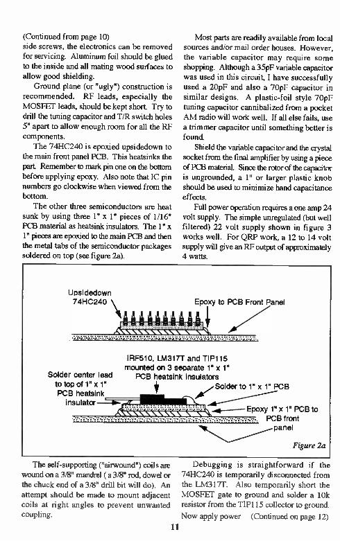
Some Tips On VFO Stability Doug DeMaw, W1FB
P.O. Box 250 Luther, MI 49656
VFOs continue to be an important part of the QRP person's amateur equipment,
but inexperienced builders are frequently troubled by long-term drift problems. A VFO that won't settle down and remain on fre-quency after 10 or 15 minutes is often worse than having no VFO at all. The malady is compundecl further if the person who is receiv-ing the unstable signal is using a receiver with
a 250- or 500-Hz CW filter. The drifter's signal can vanish from his receiver passband
quickly! This article offers some down-to-
earth procedures for minimizing short- and long-term drift
As RF current flows through the frequency-determining rapacitors in an oscillator, there is
a certain amount of internal heating that causes minute changes in the capacitance. To a lesser extent we observe the same phenomenon with
resistors in the critical parts of the oscillator circuit Therefore, it is prudent to use capaci-tors of fairly large geometry in the feedback
19
circuits (such as in a Colpitts oscillator). This minimizes the overall internal temperature change. I prefer 1/2-watt carbon resistors for the same reason. Capacitors of small geom-etry may be used in parallel to obtain the desired value, and this will increase the inter-nal area to reduce the effects of heating. NP zero (NPO) capacitors are probably the best choice for the VFO designer. I have found
that American made NPOs exceed the im-ported ones for stability. These capacitors maintain their values over a fairly wide range of temperature. Mouser Electronics in Texas is a supplier of NPO capacitors.
My second choice is the polystyrene capaci-tor, which has a slight negative temperature coefficient This can be advantageous when powdered-iron cores are used in the VFO tank circuit, since powdered iron has a positive drift characteristic. The polystyrene capacitors tend to compensate for this positive drift trait Fur-thermore, polystyrene capacitors have a high

Q, which is important in oscillator circuits. Silver mica capacitors are the least stable of the three types under discussion, especially in circuits that operate above, say, 3.5 MHz. No two equal value silver micas from a given
production batch seem to have the same tem-perature characteristics, according to tests I
have performed. Some were very stable, some had negative drift and some showed positive drift at 72 degrees F.
Variable Capacitors
Tuning capacitors with aluminum plates are temperature-sensitive and should be avoided. Try to find variable capacitors with plated brass or steel plates for your VFO. They should be double-bearing types (a bearing at each end of the rotor) so that the mechanical
stability is good. The capacitor should turn easily when grasping the shaft with your fin-gers, and the rotation should not be lumpy. Those units with ball-bearings are the best choice for VF0s.
Trimmer capacitors can be a source of fre-quency instability in a VFO. If you must use ceramic trimmers (avoid plastic or mica trim-mers), be certain they are of the NPO class. I prefer using miniature air-variable trimmers in my VF0s, if there is ample space for install-ing them. They should be mounted on the VFO PC board near the tuned circuit
Coils and Core Material
An ideal VFO would contain a rigid, high-Q, air-wound inductor. It would be enclosed in a proper shield and would be mechanically stable. Unfortunately, in this era of miniaturization, there are few builders who are willing to con-struct a fairly massive VFO. So, ferromag-netic cores are the rule rather than the excep-tion. Slug-tuned or toroidal coils are the favor-
ites of most of us. Choosing the right core material is perhaps the most important part of the design effort with respect to frequency stability.
Powdered-iron cores are the most stable ones to use. Avoid ferrite cores at all costs. The
wrong powdered-iron type will not only in-crease unwanted drift, but it can ruin the coil Q. No. 6 core material (yellow coding) is made from carbonyl C and is a good choice for
stability at HF. this material is used for toroids and slug-tuned forms. Amidon Associates presently has an even better tonaid core mate-rial (white coding), but my older catalogs do
not list this type, so I can't supply the part number. The photograph on page 18 shows a collec-tion of parts for a VFO I built The coil is slug-
tuned and is a J.W. Miller 43 series part The coil Q is high and the mechanical integrity of the slug screw and collet is excellent. The latter trait prevents drift from slug movement versus heat and vibration. The small PC-mount coil on the circuit board is in a noncriti-cal part of the circuit (buffer stage), so its quality is not related to drift The tuning capacitor is of the double bearing type, as mentioned earlier. A miniature air-variable trimmer can be seen at the left end of the PC board. Two large polystyrene capacitors are visible to the right of the trimmer. VFO circuits of this type are described in detail in WIFB's QRP Notebook (2nd. edition) and W1FB's Design Notebook. Both are available from the ARRL and PC boards for the VFOs are sold by FAR Circuits in Dundee, IL. If you use a toroid in your VFO tuned circuit, be sure to coat the winding with two layers of Polystyrene Q Dope. This will prevent the turns from moving during vibration or when the ambient temperature changes. Do not mount the toroid flat on the PC board. Rather, install it vertically and affix the bottom of it to the PC board with epoxy glue. If you can't obtain GC Polystyrene Q Dope, you may sub-
stitute Elmer's wood glue or the equivalent. I have found it to be very durable and it does not alter, the Q of the coil once it has dried.
Mechanical Tips
Do not use double-sided PC board for VF0s. The etched elements, in combination with the ground-plane side of the board, form unwanted
capacitors that are (Continued on page 22)
20

(Continued from page 21)
very unstable. Use only high quality glass-epoxy PC board material. Phenolic boards are not recommended for VF0s.
Enclose your VFO in a shield box and isolate the stages that follow the oscillator by install-ing a shield partition between them and the
oscillator part of the box. This will prevent heat from migrating to the critical oscillator components. Vent the portion of the box that contains the non-oscillator circuitry. Keep all component leads as short and direct as practi-cable.
Closing Comments
Short-term drift occurs during the first three minutes after VFO turn on. This is caused by heating of the transistor junction and initial
heating of the associated components. Long-term drift is the least desirable of the two conditions, and can last for hours with a poorly designed VFO. It should never exceed 30 minutes, and 100 Hz of drift is the maximum amount you should accept When checking
the drift of your VFO with a frequency meter, be sure to terminate the output of the VFO with a resistor that represents the characteristic load
it will look into when attached to your trans-mitter. Connect your frequency meter across this load resistor.
Avoid using varactors (tuning diodes) in place of air variable capacitors when you build a VFO. The junctions of tuning diodes un-dergo a significant change in internal tempera-ture during operation, and this causes prohibi-tive changes in the overall circuit capacitance.
• • •
Parts Placement Diagram: K6EIL Receiver (pg.27)
21

Neophyte Motogeime The Second Report In An Ongoing
Compilation Of Neophyte Information
The Neophyte was designed by John Dillon, WA3RNC of Lewistown, PA. A direct-conversion type receiver built around the Signetics NE602N mixer/oscillator IC, and
originally conceived for 80 or 40 meter operation, it previewed in the February, 1988 issue of QST, and stimulated much interest in the ham-builder community. Low noise, good sensitivity and lack of hum/microphonics, along with good frequency stability made it a contender to function on a communications level.
4
VE7GC Neophyte 'S' Meter Mod
Calibrating resistor
I
1
TH-_ U2 +
SW1 D1 e 6VDC
6
Ml: 250pA Meter
IF Cl 9 -I- 470mF J. 10V =
V
1 000
U2: Stock Neophyte LM386 Calibrating Resistor: Try 10k or 5k
The Dick Pattinson (VE7GC) S-Meter mod incorporates the addition of three elements: a 1000 resistor in the power line to the LM386 audio amp, a 250 microammeter and a variable calibrating resistor of, say 10k.Q. This would
indeed form a kind of signal strength meter and Dick notes the 1000 resistor acts as a form of AGC, as the current to the 386 is reduced on peaks. Dick says he has carried this further and applied this varying voltage to control the gain of an RF stage ahead of the Neophyte: this will appear in the Summer, '94 Issue of Hambrew!
22

The W6EMT 10 Meter Receiver Roy Gregson, W6EMT 13848 SE 10th., Bellevue, WA 98005
23

When the FCC authorized part of 10 meters to the Novices, a new Novice friend was in need of a 10 meter receiver for listening to code practice in the evenings. The "Neo-phyte" seemed a simple approach. Since this was intended to be a "one or',
ugly construction was used with excellent re-sults. Stability would be of major consider-ation in a receiver for 10 meters. The stability comes from series-connected polystyrene caps, an air-wound inductor (no toroids!), good volt-age regulation, heat treating in the oven and sticking everything down with Super Glue. The drift is such that after about 1.5 hours listening on one frequency, a slight retune may be required. The double-tuned front end was necessary
to keep the CB'ers out (at least those not on 10 meters). I used Mouser P/N 421F-123 IF cans, and removed the built-in cap on the bottom of the IF cans. It's only necessary to break the thin ceramic cap so there is no connection. The 10pF caps resonate the cans on 10 meters. The 22 and 330 pF caps couple the two tuned circuits together. Li is close air wound with #20 wire, .300
ID. I used a round wood pencil for a form. Don't space the turns. I formed the end wires for soldering in place, then soaked the entire coil with superglue to hold it together. When dry, scrape the enamel of the ends for solder-ing. I don't believe superglue fumes are good to breathe, so keep it off the soldering areas. This sure beats winding toroids! And no heating problems with the core material (air)! I used a trimmer cap with a brass screw as used for VHF. I don't know the part number (see notes). You could use trimmer pots on each side of the main tuning pot to set the band limits if desired. Arrange the oscillator ca-pacitors, the 100,680 and 56pFs to stack like "cordwood". Make the series connections, and arrange leads out of the stack to line up with their next connections. I can't honestly say that this is the "secret" to stability, but it did the job. The 10pF cap between pins 6 and 7 of the NE602 and the padder across Li are actu-ally two 22pF silver mica capacitors in parallel (11pF).
24
The audio section uses a 2N3904 for a preamp. An active filter from the ARRL Hand-book or the Variable Bandpass Filter from page 12 of the Autumn Issue of Hambrew would work great for CW selectivity. It can be switched in and out The popular LM386 AF amp rounds out the receiver.
When complete, alignment and calibration is accomplished using the station receiver. Since this is a direct conversion receiver, the
oscillator signal will be quite loud in the sta-tion receiver. If desired, adjust the tuning range of the main tuning pot with trimmer pots as suggested. Measure the pot resistance val-ues and solder in fixed resistors of the same values. Set the band edge with the trimmer capacitor. Connect an antenna, find a signal to peak T1 and T2, and be amazed at how well a simple receiver works. When complete, heat the receiver in your
oven at a low heat for a few hours. Low heat means after a quarter of an hour you can hold it in your hand even though it feels quite warm. With the "heat treatment" finished, re-
check alignment and glue down the "cordwood-stacked" capacitors and Li with superglue. When completely dry, check for final align-ment. My receiver tunes from 28.000 to 28.600
Khz. Sideband signals sound good for such a simple rig. For its original intention, this receiver does a good job and hears all but the very weakest signals when compared with the main rig. • •
Note: All parts are available from Dan's Small Parts and Kits, 1935 So. 3rd West #1, Missoula, MT 59801
Ed. Note: Harnbrew willfrature a construction article by Roy in the upcoming Summer, 1994 Issue - a great VXO 80 Meter Transmitter project. This VXO really swings - don't miss iLl

Improved Neophyte Receiver
Wes Baden, K6EIL 3914 Parkview Drive, Salt Lake City, UT 84124
WA3RNC's "Neophyte Re-ceiver" (February, 1988 QST, re-printed in QRP Classics) was imagi-natively designed and even elegant in its simplicity. However, the re-ceiver suffered from two flaws: low speaker volume and poor signal se-lectivity. Homebrewers such as Doug DeMaw, W1FB (11-88 Receiver Design Notes) quickly offered solu-tions to these problems by suggest-ing the inclusion of an AF preampli-fier and audio filter between the prod-uct detector and AF amplifier stages.
My NE602 receiver for 40 meters incor-porates an AF preamplifier and a bandpass audio filter. There now is no problem driving a 2 1/2 to 3 inch speaker to room-level volume. Also, selectivity is significantly improved.
The NE602AN product detector is fol-lowed by a low-noise 2N5089 AF preampli-fier. R6 sets stage gain and can be experi-mented with. C15 provides some high AF roll-off even before received signals reach the audio filter. The heart of the filter is a low-noise TL081 op amp. I have found out, by the way, that garden-variety 741 op amps do not work well in this circuit You will need to spend the extra money and get a TL081 or its equivalent (e.g., Mouser NTE857M).
See N1AL's "Active Filters" (July, 1980 QST, reprinted in QRP Classics) for a full description of the audio filter. R9 sets the bandpass center frequency (a value of 2.2k ohms equals 750 Hz). Increasing R9 to 4.7k ohms would drop the center frequency to approximately 500 Hz. It is important that C18 and C19 be good quality polystyrene capacitors, with 5 percent or less tolerance
(Mouser Me 23PW310 or equivalent). Match the capacitors closely if you can.
Selectivity of the "Neophyte Receiver" was 1 kHz at -3 dB and a full 7.5 kHz at -20dB. With the addition of the TL081 audio filter, selectivity in my receiver increases to 150 Hz at -3 dB and 850 Hz at -20dB. This is a noticeable improvement However, selectiv-ity will not rival that found in a $150 crystal filter (typically 850 Hz at -60dB). Q in my audio filter is a modest 5. The attenuation curve is not steep. Indeed, filter skirts fall off sharply below -20dB. In hindsight, I would cascade the audio filter, perhaps using a dual op amp, to improve selectivity even further.
The use of low-noise devices 2N5089 and TL081 makes for an extremely quiet re-ceiver. There is virtually no internal receiver noise during operation. R1 can be used to decrease external receiver noise so that sig-nals often can be listened to with little or no underlying hiss. The inherent sensitivity of the NE602AN is readily apparent In casual listening the first night that I built my receiver, I was able to hear CW signals from all conti-
25

26

nents except Africa. KF9GX at FAR Cir-
cuits designed the circuit board for my receiver. Etched and drilled boards are available at $6 ppd. from FAR Circuits, 18N640 Field Court, Dundee, IL 60118.
PARTS LIST Cl 70 pF min. cer. trimmer cap (Mouser ME 242-1270) C4, C5 270 pF NPO monolithic cer. cap. (Mouser ME 21RR627) C6, CS 120 pF NPO monolithic cer. cap. (Mouser ME 21RR612) C7 25 pF air variable cap. C9 10 pF NPO min. ceramic trimmer cap. (Mouser ME 242-2710) C18, C19 .01 uF 5% polystyrene cap. (Mouser ME 23PW310) Li T-50-2 toroid. Sec. 26 turns #26 enamelled wire, pri. 1 turn
#26 closewound over bottom of sec. L2 T-50-6 toroid: 22 turns #26 Q1 2N5089 Ul Signetics NE602AN U2 TL081 (Mouser NTF.R57M or equiv.) U3 LM386 Capacitors are miniature or monolithic unless indicated. Polarized capacitors are tantalum or electrolytic. All resistors are 1/4 watt Etching Pattern (Actual Size)
27
Parts placement diagram on page21

Amateur Radio QRP Design and Construction, Part II
Using Transistors and Integrated Circuits Bruce O. Williams, WA6IVC MXM Industries, Smithville, Texas 78957
Last month we discussed the identification of some of the more
common types of components we use in the design and construction of QRP equipment. That discussion was certainly not exhaustive, and we will refer to identification of com-ponents more in the future. This installment will discuss the use of transistors versus integrated circuits. Don't expect a lot of theoretical dis-cussion - the theoretical aspects of transistors are covered nicely in sev-
eral different tomes. I recommend the ARRL Handbook and any of several works written by Doug DeMaw, W1FB, also avail-able from ARRL.
Early Use of Transistors
The transistor was invented in the late 1940s, but didn't appear for use by hams and experimenters until the late 1950s or 60s. Why? Because they were not very good in terms of frequency capability, and they were horribly expensive! I can remember, in 1958, that the so-called experimenter's transistor (2N107) and the HEP series of transistors cost
more than a vacuum tube. The architects of history proclaimed that transistors would never
find a place in Amateur Radio, and the Ameri-can Amateur Radio Industry believed them! Fortunately the Japanese electronics industry either never heard THE WORD, or else they ignored it - they went right ahead and started using transistors, depending on the develop-ment of better and better transistors as time passed. They were eminently successful, as
Today, transistors offer many advantages for the QRP designer and builder - they are small, operate at low voltages, develop very little heat, and are very adaptable in circuits. They may be used in many different types of construction, such as printed-circuit boards, "dead-bug" assembly, and point-to-point wir-ing on perfboard.
What does this mean to us "fiddlers"? Well, for a few bucks we can lay in a supply of solid-state devices to allow us a wide latitude
of choice for out designs. Transistors are available at many parts houses for literally pennies. Digi-Key has a large line of transis-tors available, as does Danny Stevig (Dan's Small Parts and Kits). Prices vary from five
you all know, and as a result the U.S. lost its radio industry and its electronics capability. Today, there are transistors readily available
at reasonable prices to allow us to do anything we desire with low-cost solid state circuitry.
Transistors Today
28
cents each to anything you feel you want to spend. I recommend that your basic "junk box" should have at least a handful each of the general-purpose bipolar PNPs and NPNs. Bipolar transistors, such as 2N2222s (NPN), 2N3904s (NPN), 2N2907 (PNP) and 2N3906
(PNP) and countless other types are usually available in lots of five to fifteen for a dollar. Spend a couple of bucks and have them avail-able rather than having to make a trip to the Shack, where the price may be over a dollar each! Remember - a PNP type has the collector to the negative power supply pole, and the NPN uses the positive on the collector. You can remember this by looking at the diagram for the device - current flows in the direction of the arrow.
There are many uses for discrete compo-nents, to be sure. When you need an oscillator there is no substitute for a transistor. Field-effect transistors provide an easy way to get an oscillator cheap and fast. Put a few JFET transistors in your junk box. Try the MPF102 or 2N5486.
Again, the market provides us with the chance to get JI-Els at the price of bipolars. There is a different problem with dual-gate MOSFETs, however. Like most dual-gate MOSFETs, the old reliable 40673 is appar-ently out of production, but that may be con-sidered somewhat of a blessing by many de-signers. Its main application was as a mixer, but there are several better devices available now as integrated circuits (ICs). If you find a few 40673s, grab them! They may be useful at some time.
Integrated Circuits (ICs)
I once attempted to build a kit furnished
by a company that was based in Australia. It was a transceiver and the design was all dis-crete components. The audio output stage
took up about 4 square inches of board space, and had about 10 different transistors in it. Today, this entire stage could be replaced with an 8-pin DIP (dual-inline package) with only about 5 discrete components. (I never did get the thing to work!)
That's the beauty of ICs. They work very well and can replace several transistors and their associated discrete components. I don't like, and refuse to use the LM38b in any of its variations. It is noisy (death to a receiver), can oscillate at audio frequencies, and requires lots of attention to grounding. The LM380, either in the 14-pin configuration or the 8-pin con-figuration does a much quieter job if you can get by with 34 dB gain. If you need an audio device with more gain, or variable gain, I guess you might be stuck with the LM386. The problem with all, or almost all of the audio chips is that they are included in the design at maximum gain. Along with maxi-mum gain goes maximum internally gener-ated noise. This means that the device is pumping along generating maximum noise no matter what the level at the input
If someone would come up with an audio chip with electronically controlled gain, what a good thing that would be. Well, Signetics has done it! Their TDA7052A/AT is an 8-pin DIP with DC volume control. They are not widely available, but I cot my hands on a couple of samples. I'm still working on using them, and they show a lot of promise. Until they're widely available, however, we're stuck with the present selection.
Invest in a few audio amplifier chips for your junk box. It doesn't make much differ-ence which you use, but any of them will save you a lot of headaches in designing audio circuits. Try the 14-pin LM380 (2W), the 8-pin LM380N-8 (0.6W), the LM386, the LM394 (5W), or the LM389 (18-pin DIP with three general-purpose bipolar NPNs in the pack-age). I've been playing with the LM389 with
a view toward a one-chip transceiver. Try it! It only has about 250mW output, but that's enough for 'phones.
There are several other interesting 8-pin ICs for other applications. The Signetics NE602AN has been a favorite of designers for a long time. For every devotee of the 602,
there's at least one detractor. Most criticism of the 602 has been because of its "low dynamic range". This may be true in part, but properly used the 602 is a fine (Continued on page 44)
29

20/20 Hindsight Looking Back Into Past Issues • Updates & Elaborations
Fred Bonavita, W5QJM, pointed out that the capacitor values sidebar in the Winter, '94 Issue on page 12 lacked a value marking in one section. The values were in microfarads as below:
2n2 = .0022pF 102 = .001pF 472 = .0047pF
Fred also mentioned the lack of a value on the input (gain) pot in the Neophyte schematic. It is 10kS2:
Ti
Autumn, '94 Issue
With the passing of Wes Farnsworth, KEONH, we lost a good friend and fine mind.
During the final course of his illness he was unable to continue his series of articles on counterpoise and antennas. In his first article Wes asserted that the decoupling loop which he showed us would accomplish an isolation of the antenna from earth ground, and by doing so the antenna would be able to act more as a pure radiator, unaffected by surrounding objects which might detune it. Wes's claim in this regard has probably provoked more reactive response than anything we have published thus far, especially his comment that radials could be eliminated from a vertical antenna which has a decoupling loop attached. Some readers are already pursuing an investigation of this claim, in order to gain a greater understanding of the effect the decoupling loop has on the radiator in relation to it's surrounding objects and it's (Continued on page 30)
30
(Continued from page 29) angle of radiation. Certainly if the assertion is true, it has a major impact on how we think of counterpoise and how it can be applied to antennas which we construct. Experiment 1: NOKEP, Bill Mason's dipoles, constructed per directions of Wes
Farnsworth, did not lack a counterpoise in that the negative ("ground or "shield") side of the dipoles were retained (Hambrew, Autumn, '93). Experiment 2: Jane Wodening, KBOHPH: Zepp antenna described in Hambrew,
Winter, '94 Issue as constructed with decoupling loop per Wes's direction by Larry Feick (NFOZ) and Bill Mason. Result: Jane, who had not made a contact with her QRP station in over a year's time due to a ring of mountains around her cabin, achieved DX contacts on the first effort with the new antenna, and enjoyed stronger signal reception.
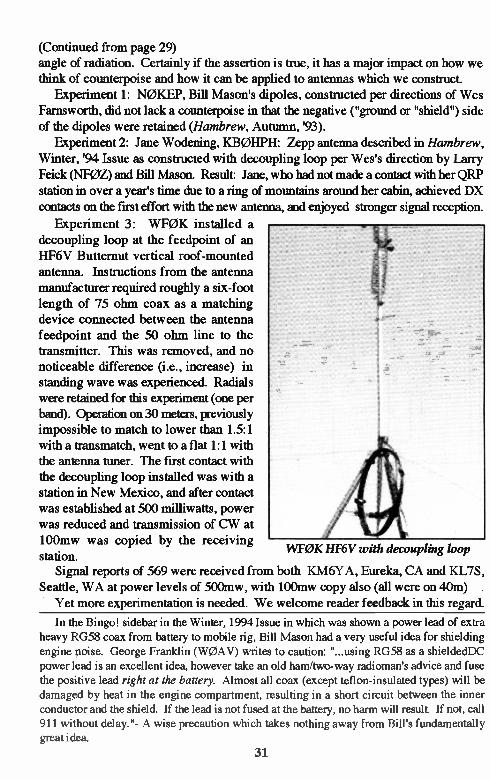
Experiment 3: WFOK installed a decoupling loop at the feedpoint of an HF6V Butternut vertical roof-mounted antenna. Instructions from the antenna manufacturer required roughly a six-foot length of 75 ohm coax as a matching device connected between the antenna feedpoint and the 50 ohm line to the transmitter. This was removed, and no noticeable difference (i.e., increase) in standing wave was experienced. Radials were retained for this experiment (one per band). Operation on 30 meters, previously impossible to match to lower than 1.5:1 with a transmatch, went to a flat 1:1 with the antenna tuner. The first contact with the decoupling loop installed was with a station in New Mexico, and after contact was established at 500 milliwatts, power was reduced and transmission of CW at 100mw was copied by the receiving station. WFOK HF6V with decoupling loop
Signal reports of 569 were received from both KM6YA, Eureka, CA and KL7S, Seattle, WA at power levels of 500mw, with 100mw copy also (all were on 40m) . Yet more experimentation is needed. We welcome reader feedback in this regard.
In the Bingo! sidebar in the Winter, 1994 Issue in which was shown a power lead of extra heavy RG58 coax from battery to mobile rig, Bill Mason had a very useful idea for shielding engine noise. George Franklin (W0AV) writes to caution: "...using RG58 as a shieldedDC power lead is an excellent idea, however take an old ham/two-way radioman's advice and fuse the positive lead right at the battery. Almost all coax (except teflon-insulated types) will be damaged by heat in the engine compartment, resulting in a short circuit between the inner conductor and the shield. If the lead is not fused at the battery, no harm will result If not, call 911 without delay."- A wise precaution which takes nothing away from Bill's fundamentally great idea.
31

The TwoFer III - Salvation
John P. Christopher, NG7D
The best way to describe the Two-Fer III-Salvation transmitter in one word: Slick! Hav-ing built several differently-designed Two Fer transmitters in past years, I have come up with a version that incorporates something missing from a lot of small QRP transmitter designs by
most home brewers: a sidetone oscillator cir-cuit The addition of a sidetone oscillator within the circuit will add flexibility to your QRP operating fun by allowing you to work split frequency operation on the band. That is, you remain on your crystal or VXO frequency
to transmit, but you can now QSY up or down the band on your receiver to copy contacted
stations if the need arises. Your contact zero
beats your signal in on his receiver, but he transmits on another frequency, for example
up the band 15 Khz, having you zero beat him in on your reePiver. It works, and can salvage
your QS0s from total disaster during periods of heavy QRM. The best feature is that this maneuver does not require two VFOs for suc-cess.
The Two-Fer III-Salvation transmitter is a 32

Component List: TwoFer HI Salvation
RI 1.5K 1/2 Watt Resistor Q1* R2 1K 1/2 Watt Resistor Q2 R3 10K 1/2 Watt Resistor Q3 R4 1.5K 1/2 Watt Resistor R5 1K 1/2 Watt Resistor Q4 R6 100K 1/2 Watt Resistor R7 470Q 1/2 Watt Resistor R8 2.2K 1/2 Watt Resistor VR1 R9 33Q 1/2 Watt Resistor VR2 R10 47Q 1/2 Watt Resistor
X1 Cl 0.1uF Ceramic Disc Cap 25v DC C3 .01uF Ceramic Disc Cap 25v DC C5 .022uF Mylar Cap 25v DC C6 .01uF Ceramic Disc Cap 25v DC C7 0.1uF Ceramic Disc Cap 25v DC C8 0.1uF Ceramic Disc Cap 25v DC C9 .01uF Ceramic Di sc Cap 25v DC C10 50-100 pF variable Tuning Cap C11 39pF Ceramic Disc Cap 25v DC C12 0.1uF Ceramic Disc Cap 25v DC C13 47pF Ceramic Disc Cap 25v DC C14 470pF Silver Mica Cap 500v DC C15 1000pF Silver Mica Cap 500v DC C16 470pF Silver Mica CaP 500v DC C17 10uF Electroldic Cap 25v DC C18 0.1uF Ceramic Disc Cap 25v DC
DI 1N914 switching diode D2 1N914 switching diode ZD1 1N4752(33V)lwattZenerDiode
Ul NE555 Timer Chip
TIP 30 PNP Switching Transistor MPF102 1-E1 Transistor 2N2222A NPN Transistor (Heat sink recommended)
2N3 553 NPN Power Transistor *( TO-5 Heat Sink required)
500 ohm potentiometer-RF Control 100K potentiometer-Side tone
HC6/U or HC33 Fundamental Crystal for 7 Mhz band. (7040 KC)
T FT50-61 Toroid Core Transformer Wind 25 turns #26 enamelled copper wire for the Primary points 1 and 2. Wind 5 turns #26
enamelled copper wire over center of primary winding, points 3 and 4, for
secondary winding.
RFC1 Ferrite Bead FB73-801: Wind 13 turns # 28 enamelled copper wire
through center of bead. RFC2 Ferrite Bead FB73-801: Wind 13 turns # 28 enamelled copper wire through
center of bead
Li T50-2 Toroid Core: Wind 45 turns #28 enamelled copper wire.
L2 T50-2 Toroid Core: Wind 14 turns #24 enamelled copper wire.
L3 T50-2 Toroid: Wind 14 turns #24 enamelled copper wire.
*TIP 41 may be substituted for Ql
Note: C2 and C4 were eliminated from this schematic and component list
33

The "Salvation", showing placement of controls and jacks
transistor-switched, Pierce Crystal VXO-con-trolled oscillator. The crystal oscillator is
activated whenever the transmitter is keyed to ground by Q1, or the spot switch is closed. The oscillator frequency can be varied by the use of a 50 to 100pF air-variable capacitor (VXO) within the oscillator circuit. The signal from the oscillator (Q2) is then
fed into a Driver/Amplifier stage (Q3), where the RF output may be adjusted with the use of the VR1 500 ohm pot It is important to note that it is a must to include the R10 resistor (47 ohm) from the emitter lead of Q3 to the VR1
pot for biasing. Without this resistance, Q3 will destroy itself upon key down. An imped-ance-matching toroidal transformer (Ti) is
included within this stage, increasing RF power output The signal is then amplified further by
being fed to a broadband class C RF amplifier stage at Q4. From here, the signal proceeds into a two-stage lowpass HF filter for har-monic suppression before transmission.
A QSK receiver input line is attached to the input of the lowpass filter stage to enable transceive operation with an external receiver.
With the transmitting antenna attached to the output of the lowpass filter, signals flow to the receiver connected to the QSK input line dur-
34
ing non-transmit periods. The QSK circuit consists of a capacitive/ inductive resonant circuit for 40 meters. Reversed switching diodes prevent damaging transmitted RF from entering the receiver front end.
The added sidetone oscillator and associ-ated stages are controlled and powered through a TIP 30 switching transistor. When powered by 12 to 13.8 volts DC and keyed to ground, the switching transistor opens with necessary volt-age to circuits, acting as a switch: key down =
ON, key up = OFF. VR2 is a 10k potentiometer that will allow adjustment of the audio output from the sidetone oscillator during transmis-
sions. This audio can be monitored by an 8 ohm speaker, a piezo speaker element (a pretty amazing device in itself) or headphones.
A 33 volt 1 watt zener diode is placed on the output of the final amplifier stage and ground to prevent excessive VSWR damage or volt-
age spikes to the final transistor, should a short circuit or open line condition on the antenna occur. The transmitter is capable of producing an average of 2 to 3 watts RF output, and is fed into a 50 ohm load at the antenna. It is advis-able, though, to keep the power to a 1.5 to 3
watt RF output maximum limit to protect the final transistor and to keep thermal heating of

the device to a minimum. VRI should be able to drop the output power into QRPp ranges for further fun and excitement, if you desire. The use of a TO-5 or similar heat sink will be required, as could be expected. FT-243-style fundamental quartz crystals
may be used with this transmitter. These are still pretty common for 40 and 80 meters, and are not difficult to obtain at Ham flea markets and crystal manufacturers. However, accord-ing to the ARRL Handbook and various ar-ticles written by Doug DeMaw, HC6/U-and HC33/U-type quartz fundamental crystals will provide better frequency shifting and stability with VXO control than the FT-243s. AT-cut HC6/U-types can shift from 5 to 15 Khz or more at 7 Mhz. In some circuit designs, they are known to shift as much as 45 Khz or more. Usually a swing this great will produce an unstable oscillator, which we do not want on the air. It is desirable then to shift the fre-quency a small amount to keep things stable within the oscillator, so a 3 to 5 Khz swing would be reasonable to have. Crystals nor-mally swing upward in frequency with VXO
control from my past experience, but some lowering from the crystal frequency could also be possible, so beware if you are working near band edges. Once you have a crystal of known fre-
quency accuracy, make a note of the shift that the VXO produces and use one or more crys-tals according to your needs. HC6/U-and HC33/U-types will more than likely have to be manufactured for you by a crystal manufac-turer, since these types are not very common on the surplus amateur radio market FT-243s are still fun to play with, and will suffice until better crystals with which to operate can be found. New crystals cost a few dollars, but they will give better performance and flexibil-ity in the long run. I picked the 40 meter amateur band for
which to design this transmitter for several reasons. First, there is more band activity per 24 hour period. I believe that 40 meters will net the QRP operator more QS0s per period than on any of the other amateur HF bands when averaged out in a years time, working stations during day and nighttime hours. There
NG7D selected label tape for control labels
35

The Two-Fer III Salvation: Neatly Laid Out!
always seems to be CW activity on 40 meters. Second, fundamental quartz crystal are more available for the 7 MHz band with FT-243 crystals often found by the box load at ham swap meets. Third, the less odd-valued com-
ponents required by the circuitry: most parts used on this transmitter design can be obtained
at any electronic parts shop or Radio Shack store. Since the circuit design presents no problems in construction, it is easy to bread-board on a piece of 6" x 4" perfboard, using point-to-point wiring techniques, a notable characteristic of a homebrewed project.
A side benefit of this transmitter design is
the fact that it is not limited to use only on the 40 meter band. This basic circuit can be
adapted for use on other amateur HF bands with simple conversion modifications to the Low Pass Filter Stage, the Receiver Input Line Stage, changing the fundamental crystal and some parts. That's it! The rest of the circuit
36
remains the same always and no further changes should be required. The modification process involves rewinding filter toroids and changing four capacitor values in the circuit The trans-mitter can be designed for use on 160 meters through 10 meters. RF output though, will vary as the frequency bands are increased upward in the spectrum. However for the Rig-0-Rama event, I have confined my design to
just the 40 meter monoband design, and will not present additional coil-winding data.
By the way, video cassette cases do make perfect enclosures for radio projects, espe-
cially if you own a Dremel hand tool. It drills and cuts through the plastic material just like
butter, if used properly. My radio-building tools aren't complete without one. So, fellow builders, has my project created
some interest and curiosity within you? Like all things in life, there is always room for
improvement, and my design is no exception.

Any further ideas on how to improve on it are always welcome. Get those soldering irons hot, mid those junk boxes for parts, get the parts orders in to the QRP parts suppliers and get ready for a true adventure in QRP building. 72 for now, and happy building De NG7D • • •
• Neophyte Roundup, Summer, '94 Issue: Adding a bandspread to the Neophyte •
RIG-0-RAMA! DEADLINE EXTENDED: JUNE 1, 1994
THE BEST ARTICLEJDESIGN FOR A MONOBAND TRANSMITTER EARNS
$200.00 AND COMPLEXITY DOES NOT NECESSARILY
MEAN IT'S A WINNER-A SIMPLE CIRCUIT COULD DO THE TRICK!
CERTIFICATES FOR ALL ENTRIES - AWARDS TO RUNNERS-UP POB 260083
Lakewood, CO 80226-0083
Decision of the judges is final. All submissions are subject to publication by Hambrew. Manuscripts returned if S.A.S.E. included. Void where prohibited by law.
Not void where not prohibited by law. Subject to whim. Have fun or don't bother!
37

Add Narrow Band Sweep To Your Signal Generator
John Pivnichny, N2DCH 3824 Pembrooke Lane, Vestal, NY 13850
Photo A: Frequency Sweep of 8 MHz Crystal Filter
A minor modification to practically any signal generator will let you look at frequency sweeps of your narrow band IF filters or trans-formers. Any oscilloscope will do for the dis-play, even my ancient Heathkit 0M-1, since the required bandwidth is under 100 kilohertz Photo A shows an actual sweep of my 8 MHz crystal filter described in reference [1].
Use A Varicap
You will need to add the circuit of figure 1 to your signal generator. The most important part is the voltage variable capacitor diode, VVC, which changes its capacitance as the voltage across it changes. When connected to
the oscillator tank of your signal generator, this capacitance change causes the frequency change needed to display a frequency sweep. If the sweep is kept narrow, then nonline,arities in the frequency vs voltage characteristic will be minor and can be neglected for amateur accu-racy. Inductor LI, a radio frequency choke, iso-
lates the if circuit from the control voltage. Potentiometer RI provides a sweep width con-trol. Resistors R2 and R3 set the steady state bias on the WC at 2 volts, so that a +/- 1 volt sweep signal will not drive the diode into conduction. I added all the components to the back
panel of my homebrew signal generator [2], as shown in Photo B. For other generators you
38

will have to locate the oscillator tank circuit and find a nearby point to mount the potientiometer and phono connector. The 40 pF coupling capacitor can be increased or decreased as necessary to set the maximum sweep width. With my generator, 40 pF pro-duces over 30 kHz sweep width.
Sweep Signal
Where does the sweep signal come from? To keep things easy, the sweep signal is taken
from a sweep output terminal on the oscillo-scope. On the Heathkit scope there is a 1 volt peak to peak 60 Hz sinewave available on the front panel near the vertical input This makes an ideal sweep source. Most scopes will have something similar, just make sure it's peak to peak amplitude is in the range of 1-2 volts and the frequency down below 100 Hz. The sweep signal is the same signal used to
move the spot horizontally across the face of
the scope. There is no problem syncing the trace since the signal frequency motion and spot motion occur together.
Detecting the Signal
Many older scopes have a greatest vertical sensitivity of about 0.1 volt per inch of vertical deflection. If you want to check out crystal filters, you don't want to put anywhere near a 0.5 volt signal through them (for a 5 inch display). The crystals can't take that kind of power. What's needed is additional amplifica-
tion. In addition, an if detector circuit is needed to convert the signal level into a dc voltage. The circuit of figure 2 does the job of
amplifier and detector. A single MC1350 IF amplifier gives a gain of 10-100 (20-40 dB) allowing you to put less than 10 milivolts through your crystal filter for a full screen vertical deflection. A full wave detector using germanium diodes doubles the output provid-ing another 6 dB gain. The circuit should be built up on a 2" x 2"
piece of single sided circuit board and mounted in a metal enclosure as shown in Photo C. A suggested parts placement and hole pattern is given in figure 3, however modifications are permitted as long as pins 3 and 7 of ICI are grounded directly to the foil ground plane.
The amplifier-detector can be tested simply by feeding a steady if signal into the input jack and reading the output voltage on any voltmeter. (Continued Next Page
Photo B: Component Installation of Signal Generator Back Plate
39

You should be able to vary the output voltage from zero to plus 1 volt de by adjusting the amplitude of the input rf signal.
Typical Setup For Crystal Filter Sweep
Figure 4 shows how to connect up the equipment to observe a frequency sweep. My
test bench is shown in Photo D. The center frequency of the sweep is set by adjusting the signal generator main tuning knob until a ver-
Photo C: Amplifier-Detector
tical blip appears. With this setup you will actually get two traces, one as the frequency is swept low to high, and another as the fre-quency sweep comes back down, following the 60 Hz sinewave sweep signal. The two vertical traces can be made to coincide (al-most) as shown in Photo E by adjustment of the phase control on the oscilloscope face. There are two ways to get rid of one of the
two traces. First, you can just advance the phase control to move one trace off to the right enough to move it off the screen. A second way
Photo D: Test Bench
40

is to use the oscilloscope sweep generator to move the spot across the scope face. Again shift the horizontal position so the second vertical blip is off to the right. The sweep generator will return the spot to the left hand
side rapidly, before another vertical blip oc-
curs. This is how the trace of Photo A was generated. There will be some distortion of the frequency axis with this method because the frequency is being swept with a sinewave and the spot with a sawtooth. But a sinewave is fairly linear in the central region and that is the
part of the sweep that should be used.
Two Filters
I was able to use this setup to verify the passbands of the two crystal filters (upper and lower sideband filters) described in reference [3]. Using the first technique (phase control) I moved one blip off to the right and took a photo. Then without touching any controls I
unplugged the lower sideband filter and
plugged in the upper sideband filter. Voila, there it is shifted to the right just as expected, and I took another exposure without advanc-ing the film. This double exposure photograph is shown in Photo F. A camera tripod is needed
for such a double exposure. Undoubtedly you can think of more things
to look at with this home shack capability. IF
transformers, IF null circuits, and adjustable bandwidth features are some that come to mind.
What's Next
The vertical scale on the oscilloscope dis-play is given in milivolts per inch. For some applications, especially crystal filters, a dB scale is more useful. What's needed is a log amplifier instead of the MC1350. Two possi-bilities are the NE604 and MC3356. Perhaps some amateur out there will try one or both of these and publish his results. How about it experimenters? Let's see what we can do with our amateur equipment. • • •
References 1. J. Pivnichny, N2DCH, "Switchable Bandwidth Crystal Filter", Ham Radio, February, 1990, pp 22-29 2. J. Pivnichny, N2DCH, "Calibrated Signal Generator", 73 Amateur Radio Today, July, 1992, pp. 26-30
3. J. Pivnichny, N2DCH, "Twin Crystal Ladder Filters", 73 Amateur Radio Today, January, 1993, pp. 32-35
See additional figures and photographs, continued page 42,43 All photos in this article by John Pivnichny, N2DCH
Figure I: Sweep Circuit
41

Figure 2: Amplffier - Detector Circuit
Photo F: Double-Exposure Showing Two Filters
42
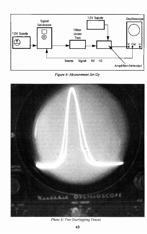
Figure 4: Measurement Set-Up
Photo E. Two Overlapping Traces
43

(Continued from page 29) little mixer chip. Used in a Hartley oscillator configuration, it provides a very low-cost solution to the mixer problem, and it is operable well up into the VHF part of the radio spectrum.
The 602 may seem like a pricey solution at about $2.50 each in small quantities, but it
does an awful lot of good things. Get a few! There's hope on the horizon, however. Signetics also makes the NE612AN - identical to the 602 except for 1 dB difference in conver-sion gain and at a price about two-thirds of the 602. I've tried them in all of my 602 circuits without finding any difference in performance. The next time I buy mixers, they will probably be 612s.
Intermediate frequency (IF) amplifiers for superhets is another area in which the use of ICs can save a lot of time and trouble. The MC1350 is readily available and not expen-sive. It is an 8-pin DIP with voltage-controlled gain. Many designers use it with AGC cir-cuitry to provide a steady level of gain through a receiver. It can be noisy, however. I prefer the MC3340, which is described as a "variable attenuator". Maximum gain through the stage is 13 to 18 dB, but it provides attenuation up to 80 dB below maximum gain to allow volume control through either a DC voltage or a vari-able resistor to ground from pin 2. The chip is quiet, and can be used in AGC circuits as well as an IF amplifier. These chips are rather expensive at about $1.60 in quantity. A good value, however.
Data
I've described several solid state devices that I'm familiar with. You will find that you need many references to allow you to pick and
choose which devices you may want to use. Always ask for supporting data when you buy
components. Try to find data and reference books in flea markets or hamfests. The shelfroom that they take is a small price for the convenience of having readily available data. My reference library contains several old ref-erence books - you never want to throw them out! Several manufacturers will provide refer-
ence material on all of their products without charge, although some of them ask a nominal fee for their books. Best bets? National Semiconductor's Linear Applications Hand-book, Signetics (Philips Semiconductors) Data
Handbook, and Motorola Linear Data Hand-book are all worth their weight in gold. There are many other sources also. The American Radio Relay League (ARRL) publishes sev-eral good reference books you need in your library. Write for a catalog to ARRL,
Newington, CT 06111. Digi-Key offers a catalog - write to Digi-Key, 701 Brooks Ave.
South, Thief River Falls, MN 56701-0677. Dan's Small Parts and Kits offers a catalog of reasonably priced parts: Dan's Small Parts and Kits, 1935 So. 3rd W. #1, Missoula, MT 59801.
Conclusion
Experiment! Try it! Find out if your idea works. Many of my commercial designs are the result of just messing around with circuits to see if they work or not. Don't be embar-rassed or frustrated if your experiments don't work. I have three large boxes full of failed experiments. I give the old boards to young upcoming hams who salvage the parts for their own junk boxes. I believe that it was Edison who said, in referring to his work on the incandescent bulb, that he discovered thou-sands of approaches that would not work - and only one that did! • • •
Bruce is the driving force behind MXIVI Indus-tries of Smithville, Texas, and is a designer of fine quality ham kits: transmitters, receivers and transceivers. His advice on designing and building comes from years ofp ractical experi-ence in the field. In the Summer, '94 Issue, Part III: Construction Techniques.
MOVING? Notify the Postal Service of your new address - don't
miss a single issue of Hambrewl
44

SHACK SNOTS
Here's a guy who knows how to homebrew - par excellence! Ernie Helton, W8MVN, of Franklin, Ohio provides us a glimpse
of an all h/b station, including power supply and tuner. In addition, Ernie has just built a station in a briefcase! There's one we'd also like to see...
Hearty congratulations on a beautiful station, Ernie!
45

CLASSIFIED ADS A Reader Service of Hambrew - No charge to subscribers to place one ham-
related ad per issue, limit 15 words, 25 cents per word thereafter. Commercial or non-commercial subscribers, no minimum. All ads must be related to amateur radio. Hambrew does not vouch for nor guarantee the reliability nor legitimacy of any item or company
represented herein. Deadlines: Sept.1 (Autumn), Dec.1 (Winter), March 1 (Spring) June 1 (Summer). We reserve the right to deny publication of any ad. Copy To:
PO Box 260083, Lakewood, CO 80226-0083. Sony, no phone orders on classified ads. Prepay only.
Wheel Antennas For UHF! 70 cm, 900 Mhz, 23 cm, 13 cm.: $39.95 each, any band! Easily stackable. Mag Wheels: Magnetically mounted versions of any of the above antennas only $59.95! Olde Antenna Lab, 4725 W. Quincy, Denver, CO 80236 (303) 798-5926 Future Issues of Hambrew will feature fol-lowup articles on Neophyte Receivers. If you built a Neophyte, we would like to include your lil' beauty! Please include a photo (b/w or color) along with any comments about mods, etc.. Send to Hambrew, PO Box 260083, Lake-wood, CO 80226-0083 J.W. Miller slug tuned ceramic inductors, used in the old QST homebrew projects. Very limited supply! SASE for list. Jeffrey Viola, 784 El tone Rd., Jackson, NJ 08527 CHASSIS AND CABINET KITS: #10 SASE 5120-H HARMONY GROVE RD., DOVER, PA 17315. 717-292-4901 EVENINGS I NEED 2SK19Y VET'S. These are for a R/S Communications receiver 460 Model. Any help will be appreciated. Need a copy of a schematic for a RCA Victor Model 97KG Su-perheterodyne. I will pay for any of the above items. Please send to Gordon Alexander, 1649 Newark, Aurora, Colorado 80010. 2N4416A FETs for sale. Prime/JAN devices in ESD pack 10/$6.00 PPD to KC5RT, 701 Oakridge, Liberty, MO 64068 For Sale: Collins RE Mechanical filters F-455-FA27-6810 2.7Kc at 455KHz PC Mount
Free 112 page catalog of electronic compo-nents, kits, test equipment, tools, books, much more. Ocean State Electronics, PO Box 1458 Westerly, RI 02891 - 401-596-3080 Builders! Hard-to-find ceramic rotary switches. Ideal for bandswitching, antenna tuners, etc. Four wafers with single pole, five positions on each. Limited supply. $5 post-paid. Limit one per person. Unfilled orders returned. Fred Bonavita, W5QJM, Box 2764, San Antonio, TX 78299-27M ELECTRONICS GRAB BAG! 500 PIECES OF NEW COMPONENTS: INDUCTORS, CAPACITORS, DIODES, RESISTORS. $5 POSTPAID. ALLTRONICS, 2300 ZANKER RD., SAN JOSE, CA 95131 Simple QRP Kits: Communications-Qual-ity Receivers, Transmitters, Guaranteed to work! SASE for catalog: MXM Industries, Rt 1, Box 156C, Smithville, TX 78957 (512) 237-3906 NEW NN1G MARK 11 CW SUPERHET TRANSCEIVER KIT. AVAIL FOR 80 ME-TERS, 40 METERS, 30 METERS AND 20 METERS PRICE $59.95 PLUS $3.75 SHIP-PING CK/MO. TO DAN'S SMALL PARTS AND KITS, 1935 SO 3RD WEST #1, MIS-SOULA, NIT. 59801. 1994 CATALOG: TWO STAMPS People are not falling all over themselves to become the Hambrew Contest Manager for the 1994 Hambrew Dash! Perhaps it's because
(not plug in). $27.50 ea., Postpaid. Henry there is no money in it! Only fame and fortune Mohr, 1005 W. Wyoming St, Allentown, PA and full price at restaurants! Have a database?
18103 You're the one! Volunteer Now! Let us know! 46

N7KSB 5/15 Watt Transmitter Additional photographs (Article on page 9)
N7KSB 5115 Watter
Completed transmitter shown next to homebrewed
case; interstage shield not shown
Comp ted transmitter showing interstage shield

OCEAN STATE ELECTRONICS QRP CW TRANSCEIVER KIT
• Covers 14.0 MHz to 14.1 MHz on 20M or cover 7.0MHz to 7.150 MHz on 40M • Available on 20M or 40M band • Superior superhet • Single signal receiver • CW crystal ladder filter • VFO tuning with vernier dial • RIT Weenier detent control • Very effective AGC • Selectable audio filter • Sidetone Oscillator • 2-3 watts of RF output • Semi break-in • 12VDC operation • Custom pre-painbd, punched & silkscreened cabaret • 100% complete kit with instuction. Nothing else to buy! • Measures (HWD) 2 1/4" x 6 1/4' 06' Weight 24 oz.
CIRP-20 20M VERSION $149.95
ORP-40 40M VERSION $149.95
MAKE CIRCUIT BOARDS THE NEW,
EASY WAY WITH TEC-200 FILM JUST 3 EASY STEPS: • Copy circuit pattern on TEC-200 film using any pain paper copier • Iron film on b copper dad board • Peel off Nm ancl etch Convenient 8 1/2 x 11 size With Complete Instructions
5 SHEETS $6.25 10 SHEETS $10.75 20 SHEETS $16.25
MAGNET WIRE Enamel coated solid copper. For winding coils, trandormers and toroids. Prices fa 1/4 lb. spools.
*14 3.85 #24 ..... 3.85 #34...... 4.80 #16 3.85 #26 3.95 #36 4.90 *18 3.85 *28 3.95 *38 5.25 *20 3.85 *30 4.00 #40 5.65 *22 3.85 *32 4.40
TOROIDS
IRON FERRITE T-25-2 40 FT37-43 60 T-25 -6 40 FT37-61 60 T-37-6 45 FT37-77 60 T-37-12 45 FT50-43 75 T-50-2 55 FT50-61 75 T-50-3 £5 FT50-77 75 T50-6 .55 FT82-43 1.00 T68-0 75 FT82-67 1.00 T68-2 75 FT82-68 1.00 168-6 75 FT114-61 2.15 T80-2 85 FT140-43 4.10 T200-2 4.00 FT240-61 8.00
WE STOCK A ¡COMPLETE LINE OF TOROIDS AND BEADS.
ID-DOPE Sdution of pure polystyrene in solvents. Dries fast and leaven a dear, protedive coating on toriods, coils and tansformers, with no or minimal effect on inductive values. May also be used as a .ment for molded or fabricated items made of polystyrene. (Bottle with Brush 2ff, oz. 59 mi) $3.75
DIGITAL CAPACITANCE/
INDUCTANCE METER DIGITAL LCR METER measures inductance,
capacitance and resistance. At Lasa An LCR meter eat
everyone can afford. Now you can measure coils, transformers,
chokes kom t pH to 200H. Capaeites from .1 pfd to 200 mfd and resistors from .1 ohms to
20 meg ohms. All in one handheld instrument
MODEL LCR-1801 ..$119.95
DELUX CODE KEY Adjustable, heavy duty brass base with ball bearing pivots. Designed for hard usage. 3/16' plated contacts. $11.75
SIGNETICS
NE602AN Balanced Mixer/OSC.
Popular IC among experimenters for DC and super-het receivers.
$2.49 ..... BUY 3 OR MORE ...$2.25
MINI-CIRCUITS SBL-1 DIODE RING MIXER
Double balance Mixer LO/RF - 1-500MHz RF DC 500 MHz
$6.75
VERNIER DIALS 1-1/2" Diameter 0-10 Marking $8.25 1-1/2' Diameter 0-100 Marking $9.25 2" Diameter (moo Marking $10.25
MINIATURE TOGGLE
SWITCHES 44 3A 125V Solder Terminals,
SPOT ON-ON $1.25 DPDT $1.50
COPPER CLAD
PC BOARDS One oz. copper, phenokc base.
r x 5" SINGLE 'SIDED ..... . $1.50 3 V.," x 6 14" DOUBLE SIDED $1.25
TO PLACE AN ORDER Call 1-800-866-6626
Ocean State Electronics,
6 Industrial Dr., P.O. Box 1458
Westerly, R.I. 02891
Mail in orders please include $4.50 shipping ALASKA & HAWAII $9.00 Minimum order $10.00 (before shipping) R. I. Residents add 7% Sales Tax
Local calls 596-3080
TRANSISTORS
RN2222A .10 2N2222A .32 2N3055 .69 2N3553 2.75 2N3866 1.05 2N3904 .10 2N3906 .10 2N4401 .13 2N4416 1.25 2N5179 .75 MPF102 .49 M RF475 6.75 M RF476 3.95 M RF477 12.50 40673 3.90 3N204 3.90
LINEAR IC'S
NE555 .35 NE564 MC1350P MC1496N LM 3177 7805 7812 7905 7912
1.75 1.09 .99 .79 .49 .49 .75 .75
MONOLITHIC
CERAMIC DISCS ONLY .1" LS.
.01µF
.047µF .25
.101.1F .28
.22tiF
.4711F
.2o
.4o
.so
DIODES
1N914 1N4148 1N34A 1N4001 1N4004 1N4007
.o4
.o4
.20
.10
.11
.14
CALL OR WRITE FOR OUR FREE 112 PAGE CATALOG 1-401-596-3080


![Notebook Neophyte to Whiteboard Warrior [d.school Pop-up Class, Oct 25 + Nov 1, 2014]](https://img.dokumen.tips/doc/110x75/55d57684bb61eb9f0d8b45df/notebook-neophyte-to-whiteboard-warrior-dschool-pop-up-class-oct-25-nov.jpg)