Embed Size (px)
Citation preview

August 2019
Sabine Pass LNG, L.P. Docket No. CP19-11-000
SPLNG Third Berth Expansion Project
Environmental Assessment
Cooperating Agencies:
Washington, DC 20426
Office of
Energy Projects

FEDERAL ENERGY REGULATORY COMMISSION WASHINGTON, DC 20426
OFFICE OF ENERGY PROJECTS
In Reply Refer To:
OEP/DG2E/Gas 2
Sabine Pass LNG, L.P.
Docket No. CP19-11-000
TO THE INTERESTED PARTIES:
The staff of the Federal Energy Regulatory Commission (FERC or Commission)
has prepared an environmental assessment (EA) for the Third Berth Expansion Project
(Project), proposed by Sabine Pass LNG, L.P. (hereby referred to as SPLNG) in the
above referenced docket. SPLNG requests authorization to construct and operate a third
marine berth at the existing Sabine Pass LNG Terminal in Cameron Parish, Louisiana.
The Project would also include the addition of piping, pipe racks, utilities, and other
infrastructure necessary to transport liquefied natural gas (LNG) to the third berth.
The EA assesses the potential environmental effects of the construction and
operation of the Project in accordance with the requirements of the National
Environmental Policy Act (NEPA). The FERC staff concludes that approval of the
Project, with appropriate mitigating measures, would not constitute a major federal action
significantly affecting the quality of the human environment.
The U.S. Army Corps of Engineers, U.S. Department of Energy, U.S. Department
of Transportation, U.S. Coast Guard, U.S. Fish and Wildlife Service, and the Louisiana
Department of Wildlife and Fisheries participated as cooperating agencies in the
preparation of the EA. Cooperating agencies have jurisdiction by law or special expertise
with respect to resources potentially affected by the proposal and participate in the NEPA
analysis.
The Project would consist of the following facilities in Cameron Parish, Louisiana:
• a new marine berth to be dredged adjacent and southeast of the two existing
marine berths along the Sabine Pass Channel;
• additional two tugs to the existing dedicated tug fleet;
• an LNG loading system consisting of a new platform, LNG loading and
cooldown lines, and LNG loading arms (two liquid, one vapor, and one hybrid
liquid/vapor);

• two new 30-inch-diameter loading lines are proposed to transfer LNG to the
Third Berth loading platform;
• an LNG spill collection system to provide spill protection for the new LNG
piping and equipment; and
• appurtenant facilities including, the customs/security building, analyzer
shelters, telecommunications systems, digital control systems upgrades,
security fencing, cathodic protection systems, elevated fire monitor towers, and
gangway with associated gangway hydraulic power unit and local control
panel.
The Commission mailed a copy of the Notice of Availability to federal, state, and local
government representatives and agencies; elected officials; environmental and public interest
groups; Native American tribes; potentially affected landowners and other interested
individuals and groups; and newspapers and libraries in the Project area. The EA is only
available in electronic format. It may be viewed and downloaded from the FERC’s website
(www.ferc.gov), on the Environmental Documents page
(https://www.ferc.gov/industries/gas/enviro/eis.asp). In addition, the EA may be accessed by
using the eLibrary link on the FERC’s website. Click on the eLibrary link
(https://www.ferc.gov/docs-filing/elibrary.asp), click on General Search, and enter the docket
number in the “Docket Number” field, excluding the last three digits (i.e. CP19-11). Be sure
you have selected an appropriate date range. For assistance, please contact FERC Online
Support at [email protected] or toll free at (866) 208-3676, or for TTY, contact
(202) 502-8659.
Any person wishing to comment on the EA may do so. Your comments should
focus on the EA’s disclosure and discussion of potential environmental effects,
reasonable alternatives, and measures to avoid or lessen environmental impacts. The
more specific your comments, the more useful they would be. To ensure that your
comments are properly recorded and considered prior to a Commission decision on the
proposal, it is important that the FERC receives your comments in Washington, DC on or
before 5:00 pm Eastern Time on September 23, 2019.
For your convenience, there are three methods you can use to submit your
comments to the Commission. The Commission encourages electronic filing of comments
and has staff available to assist you at (866) 208-3676 or [email protected].
Please carefully follow these instructions so that your comments are properly recorded.
(1) You can file your comments electronically using the eComment feature on
the Commission's website (www.ferc.gov) under the link to Documents and
Filings. This is an easy method for submitting brief, text-only comments
on a project;

(2) You can also file your comments electronically using the eFiling feature on
the Commission’s website (www.ferc.gov) under the link to Documents
and Filings. With eFiling, you can provide comments in a variety of
formats by attaching them as a file with your submission. New eFiling
users must first create an account by clicking on “eRegister.” You must
select the type of filing you are making. If you are filing a comment on a
particular project, please select “Comment on a Filing;” or
(3) You can file a paper copy of your comments by mailing them to the
following address. Be sure to reference the project docket number (CP19-
11-000) with your submission: Kimberly D. Bose, Secretary, Federal
Energy Regulatory Commission, 888 First Street NE, Room 1A,
Washington, DC 20426 NE, Room 1A, Washington, DC 20426.
Any person seeking to become a party to the proceeding must file a motion to
intervene pursuant to Rule 214 of the Commission’s Rules of Practice and Procedures
(18 CFR 385.214). Motions to intervene are more fully described at
http://www.ferc.gov/resources/guides/how-to/intervene.asp. Only intervenors have the
right to seek rehearing or judicial review of the Commission’s decision. The
Commission may grant affected landowners and others with environmental concerns
intervenor status upon showing good cause by stating that they have a clear and direct
interest in this proceeding which no other party can adequately represent. Simply filing
environmental comments will not give you intervenor status, but you do not need
intervenor status to have your comments considered.
Additional information about the Project is available from the Commission’s
Office of External Affairs, at (866) 208-FERC, or on the FERC website (www.ferc.gov)
using the eLibrary link. The eLibrary link also provides access to the texts of formal
documents issued by the Commission, such as orders, notices, and rulemakings.
In addition, the Commission offers a free service called eSubscription, which
allows you to keep track of all formal issuances and submittals in specific dockets. This
can reduce the amount of time you spend researching proceedings by automatically
providing you with notification of these filings, document summaries, and direct links to
the documents. Go to www.ferc.gov/docs-filing/esubscription.asp\

i
Table of Contents
SECTION A – PROPOSED ACTION ........................................................................................ 1
1.0 INTRODUCTION.......................................................................................................... 1
2.0 PURPOSE AND NEED ................................................................................................. 3
3.0 SCOPE OF THIS ENVIRONMENTAL ASSESSMENT .......................................... 3
4.0 COOPERATING AGENCIES ..................................................................................... 4
4.1 U.S. Army Corps of Engineers ......................................................................... 4
4.2 U.S. Department of Energy ............................................................................... 5
4.3 U.S. Department of Transportation ................................................................... 5
4.4 U.S. Coast Guard .............................................................................................. 6
4.5 U.S. Fish and Wildlife Service ......................................................................... 6
4.6 Louisiana Department of Wildlife and Fisheries .............................................. 7
5.0 PUBLIC REVIEW AND COMMENTS ...................................................................... 7
6.0 PROPOSED FACILITIES ............................................................................................ 8
6.1 Marine Facilities ............................................................................................... 8
6.2 LNG Transfer Lines ........................................................................................ 11
6.3 LNG Impoundments ....................................................................................... 11
6.4 Other Terminal Infrastructure ......................................................................... 12
6.4.1 Vapor Handling .......................................................................................... 12
6.4.2 Electrical System ........................................................................................ 12
6.4.3 Fire and Gas Detection Protection System ................................................. 12
7.0 NON-JURISDICTIONAL FACILITIES .................................................................. 13
8.0 CONSTRUCTION, OPERATION, AND MAINTENANCE PROCEDURES ...... 13
8.1 Temporary Construction Facilities ................................................................. 14
8.2 Marine Construction ....................................................................................... 15
8.2.1 Dredging and Dredge Material Placement ................................................. 16
8.3 Site Access and Traffic ................................................................................... 16
8.4 Sanitary Sewer Collection and Disposal ......................................................... 17
8.5 Operation and Maintenance ............................................................................ 17
8.5.1 Operation .................................................................................................... 17
8.5.2 Maintenance ............................................................................................... 18
9.0 LAND REQUIREMENTS .......................................................................................... 18

ii
9.1 Access Roads/Staging Areas........................................................................... 20
9.1.1 Access Roads .............................................................................................. 20
9.1.2 Staging Areas ............................................................................................. 21
10.0 PERMITS, APPROVALS, AND REGULATORY CONSULTATION ................. 21
SECTION B – ENVIRONMENTAL ANALYSIS ................................................................... 23
1.0 GEOLOGY ................................................................................................................... 23
1.1 Blasting ........................................................................................................... 24
1.2 Mineral Resources .......................................................................................... 24
1.2.1 Non-Fuel Minerals ..................................................................................... 24
1.2.2 Oil and Gas ................................................................................................. 24
1.3 Geologic and Other Natural Hazards .............................................................. 25
1.4 Paleontology ................................................................................................... 25
2.0 SOILS ............................................................................................................................ 25
2.1 Hydric Soils and Compaction ......................................................................... 27
2.2 Erosion and Revegetation ............................................................................... 28
2.3 Soil Contamination ......................................................................................... 28
2.4 Conclusion ...................................................................................................... 28
3.0 WATER RESOURCES AND WETLANDS ............................................................. 28
3.1 Groundwater ................................................................................................... 28
3.2 Surface Water.................................................................................................. 30
3.2.1 Dredging and Dredge Material Placement ................................................. 33
3.2.2 Stormwater Runoff ..................................................................................... 34
3.2.3 Water Use ................................................................................................... 35
3.2.4 Hydrostatic Testing .................................................................................... 36
3.2.5 Vessel Traffic ............................................................................................. 36
3.2.6 Conclusion .................................................................................................. 37
3.3 Wetlands ......................................................................................................... 37
4.0 VEGETATION, WILDLIFE, AND THREATENED AND ENDANGERED
SPECIES ....................................................................................................................... 39
4.1 Vegetation ....................................................................................................... 39
4.2 Wildlife and Aquatic Resources ..................................................................... 40
4.2.1 Terrestrial Wildlife ..................................................................................... 40
4.2.2 Aquatic Resources ...................................................................................... 42

iii
4.3 Essential Fish Habitat ..................................................................................... 52
4.4 Migratory Birds ............................................................................................... 54
4.5 Special Status, Threatened, and Endangered .................................................. 57
4.5.1 Federally Listed Species ............................................................................. 57
4.5.2 State-listed Species ..................................................................................... 70
4.5.3 Marine Mammals ....................................................................................... 70
5.0 CULTURAL RESOURCES ........................................................................................ 73
5.1 Survey Results and Consultation .................................................................... 73
5.2 Unanticipated Discovery Plan......................................................................... 77
5.3 Conclusion ...................................................................................................... 77
6.0 LAND USE, RECREATION, AND VISUAL RESOURCES .................................. 78
6.1 Land Use ......................................................................................................... 78
6.2 Existing Residences and Planned Development ............................................. 81
6.3 Recreation and Special Interest Areas ............................................................ 81
6.4 Contaminated or Hazardous Waste Sites ........................................................ 82
6.5 Coastal Zone Management ............................................................................. 82
6.6 Visual Resources ............................................................................................. 83
7.0 SOCIOECONOMICS.................................................................................................. 84
7.1 Population, Economy, and Employment ........................................................ 84
7.2 Housing ........................................................................................................... 87
7.2.1 Displacement of Residences and Businesses ............................................. 88
7.3 Public Services ................................................................................................ 88
7.4 Transportation and Traffic .............................................................................. 89
7.4.1 Land Transportation and Traffic ................................................................ 89
7.4.2 Marine Transportation and Traffic ............................................................. 90
7.5 Property Values ............................................................................................... 91
7.6 Tax Revenues .................................................................................................. 91
7.7 Environmental Justice ..................................................................................... 91
8.0 AIR QUALITY AND NOISE ..................................................................................... 95
8.1 Air Quality ...................................................................................................... 95
8.1.1 Regional Climate ........................................................................................ 95
8.1.2 Regulatory Requirements for Air Quality ................................................ 101
iv
8.1.3 Construction Emissions and Impacts ....................................................... 107
8.1.4 Operation Emissions Impacts and Mitigation .......................................... 111
8.2 Noise ............................................................................................................. 118
8.2.1 Existing Noise Conditions ........................................................................ 120
8.2.2 Construction Noise Impacts and Mitigation ............................................. 121
8.2.3 Ground-Borne Vibration .......................................................................... 126
8.2.4 Operational Noise Impacts and Mitigation .............................................. 127
9.0 RELIABILITY AND SAFETY ................................................................................ 130
9.1 LNG Safety ................................................................................................... 130
9.1.1 LNG Facility Reliability, Safety, and Security Regulatory Oversight ..... 130
9.1.2 USDOT PHMSA Siting Requirements and 49 CFR 193 Subpart B
Determination ........................................................................................... 132
9.1.3 Coast Guard Safety Regulatory Requirements and Letter of
Recommendation ...................................................................................... 134
9.1.4 LNG Facility Security Regulatory Requirements .................................... 137
9.1.5 FERC Engineering and Technical Review of the Preliminary Engineering
Designs ..................................................................................................... 139
9.1.6 Recommendations from FERC Preliminary Engineering and Technical
Review ...................................................................................................... 172
9.1.7 Conclusions on LNG Facility and LNG Marine Vessel Reliability and
Safety ........................................................................................................ 184
10.0 CUMULATIVE IMPACTS ...................................................................................... 184
10.1 Temporal and Geographic Distribution (Geographic Scope) ....................... 185
10.2 Projects and Activities Considered ............................................................... 186
10.3 Analysis of Cumulative Impacts ................................................................... 200
10.3.1 Geological Resources and Soils ............................................................... 200
10.3.2 Water Resources ....................................................................................... 201
10.3.3 Vegetation, Wildlife, and Aquatic Resources .......................................... 205
10.3.4 Socioeconomics ........................................................................................ 207
10.3.5 Land Use and Visual Resources ............................................................... 209
10.3.6 Recreation ................................................................................................. 210
10.3.7 Air and Noise Quality ............................................................................... 210
SECTION C – ALTERNATIVES ........................................................................................... 219
1.0 EVALUATION PROCESS ....................................................................................... 219
v
1.1 No-Action Alternative .................................................................................. 221
1.2 System Alternatives ...................................................................................... 221
1.3 Site Alternatives ............................................................................................ 221
1.3.1 Site 1 ......................................................................................................... 222
1.3.2 Site 2 ......................................................................................................... 224
1.3.3 Site 3 (Preferred Site) ............................................................................... 224
SECTION D – CONCLUSIONS AND RECOMMENDATIONS ........................................ 225
SECTION E – REFERENCES ................................................................................................ 242
SECTION F – LIST OF PREPARERS .................................................................................. 255

vi
List of Tables
Table A.5.0-1 Issues Identified During the Scoping Period ....................................................... 8
Table A.9.0-1 Land Requirements for the SPLNG Third Berth Expansion Project ................. 18
Table A.9.1-1 Proposed Access Roads for the SPLNG Third Berth Expansion Project .......... 20
Table A.9.1-2 Proposed Staging Areas for the SPLNG Third Berth Expansion Project .......... 21
Table A.10.0-1 Permits, Approvals, and Consultations for the SPLNG Third Berth Expansion
Project ................................................................................................................ 22
Table B.2.0-1 Summary of Soil Characteristics within the Project Site ................................... 26
Table B.3.2-1 Surface Waterbodies Affected by the SPLNG Third Berth Expansion Project .....
................................................................................................................... 33
Table B.3.3-1 Wetlands Impacted by the SPLNG Third Berth Expansion Project .................. 38
Table B.4.1-1 Vegetation Impacted by the SPLNG Third Berth Expansion Project................ 39
Table B.4.2-1 Habitats Affected by Construction and Operation of the SPLNG Third Berth
Expansion Project .............................................................................................. 42
Table B.4.2-2 Underwater Sound Thresholds for Fish ............................................................. 46
Table B.4.2-3 Calculated Distances to Underwater Noise Thresholds from Dredging and
Mitigated In-water Pile Driving ......................................................................... 47
Table B.4.3-1 Managed EFH Species Likely to Occur in the Project Area ............................. 53
Table B.4.4-1 Migratory Bird Species Potentially Occurring in SPLNG Third Berth Expansion
Project ................................................................................................................ 55
Table B.4.5-1 Federally Listed Species within the Project Area .............................................. 59
Table B.4.5-2 Underwater Sound Thresholds for Sea Turtles .................................................. 66
Table B.4.5-3 Calculated Distances to Underwater Noise Thresholds for Sea Turtles from
Dredging and Mitigated In-water Pile Driving .................................................. 66
Table B.4.5-4 Marine Mammals that Have Been Observed in the Gulf ................................... 71
Table B.4.5-5 Underwater Sound Thresholds for Marine Mammals ....................................... 72
Table B.4.5-6 Calculated Distances to Underwater Noise Thresholds for Marine Mammals
from Dredging and Mitigated In-water Pile Driving ......................................... 72
Table B.5.1-1 SPLNG’s Coordination with Federally Recognized Tribes............................... 74
Table B.5.1-2 Summary of SPLNG’s Cultural Resource Surveys and Consultations ............. 75
Table B.6.1-1 Detailed Summary of Land Use Affected by Project Construction and Operation
(acres) ................................................................................................................. 80
Table B.7.1-1 Existing population and Demographic Conditions ............................................ 84
Table B.7.1-2 Existing Income and Employment Conditions in the Project Area ................... 85
Table B.7.1-3 Summary of Estimated Peak Construction and Operational Workforce ........... 86
Table B.7.2-1 Temporary Housing Units Available in the Project Vicinity............................. 87
Table B.7.3-1 Public Service Data for the Project Vicinity ...................................................... 88
Table B.7.3-2 School Districts and School Enrollment in the Project Vicinity........................ 89
Table B.7.7-1 Minority Populations and Low-Income Population Information for the Census
Block Groups Within 2 Miles of the Project ..................................................... 93
Table B.8.1-1 Ambient Air Quality Standards ......................................................................... 98
Table B.8.1-2 Ambient Air Quality Concentrations in the Vicinity of the Project .................. 99

vii
Table B.8.1-3 Major Stationary Source/Prevention of Significant Deterioration (PSD)
Applicability Analysis – SPLNG Third Berth Project ..................................... 102
Table B.8.1-4 Annual Project Construction Emissions (tpy).................................................. 110
Table B.8.1-5 Annual Emissions (tpy) for Operation of Existing and Proposed SPLNG
Terminal Sources ............................................................................................. 112
Table B.8.1-6 Annual Emissions (tpy) for Marine Vessels Associated with Maneuvering and
Hoteling Operations ......................................................................................... 115
Table B.8.1-7 Annual Emissions (tpy) for Marine Vessels Associated with Transiting in State
Waters .............................................................................................................. 115
Table B.8.1-8 Summary of Air Quality Impact Analysis Results .......................................... 116
Table B.8.1-9 SPLNG Terminal, Expansion Project (Trains 5 and 6), and Third Berth
Combined Construction, Commissioning, and Operation Emissions (tpy) ..... 118
Table B.8.2-1 Baseline Sound Level Measurement Results at Noise Sensitive Areas near the
Project Site ....................................................................................................... 120
Table B.8.2-2 Pile Driving Activity Summary ....................................................................... 122
Table B.8.2-3 Daytime Construction Sound Level Impact Evaluation – Pile Driving ........... 124
Table B.8.2-4 Daytime Construction Sound Level Impact Evaluation –General Construction
and Dredging .................................................................................................... 124
Table B.8.2-5 Nighttime Construction Sound Level Impact Evaluation –Dredging Only ..... 125
Table B.8.2-6 Construction Sound Level Impact Evaluation – Overall Equivalent Day-Night
Levels ............................................................................................................... 125
Table B.8.2-7 Sound Level Impact Evaluation – Predicted Operations Noise at Noise Sensitive
Area ................................................................................................................. 128
Table B.8.2-8 Cumulative Sound Level Impact Evaluation – Marine Flare Contribution to
Operational Levels .......................................................................................... 130
Table B.10.2-1 Authorized, Planned, or Recently Completed Major Projects in the Vicinity of
the Project Considered for Cumulative Analysis ............................................. 188
Table B.10.3-1 Wetland Impacts for Other Projects Occurring within same Temporal and
Geographic Scope for Water Resources as the SPLNG Third Berth Expansion
Project .............................................................................................................. 204
Table B.10.3-2 Cumulative Sound Level Impact Evaluation for Construction of the Project and
the Sabine Pass Liquefaction Expansion Project (Train 6) ................................ 216
Table B.10.3-3 Cumulative Sound Level Impact Evaluation for Operation of the Project, Sabine
Pass Compression Project, and SPLNG Terminal Trains 1 - 6 ......................... 218
List of Figures
Figure A.6.1-1. Artist Rendition of SPLNG Third Berth Expansion Project ................................ 9
Figure A.6.1-2 Third Berth dredge area within the Sabine Pass Channel .................................. 10
Figure A.9.0-1 SPLNG Third Berth Expansion Project Land Requirements ............................ 19
Figure B.3.2-1 Third Berth Expansion Project Wetland and Waterbody Impact Map .............. 31
Figure B.3.2-2 Third Berth Expansion Project Wetland and Waterbody Impact Detail Map ... 32
Figure B.7.7-1 Third Berth Expansion Project General Location Map ..................................... 94

viii
Figure B.8.2-1 NSAs and Ambient Sound Measurement Locations ....................................... 121
Figure B.8.2-2 NSAs and Modeled Operational Noise Contours ............................................ 128
Figure B.9.1-1 Accidental Hazard Zones along LNG Marine Vessel Route ........................... 136
Figure B.9.1-2 Intentional Hazard Zones along LNG Marine Vessel Route ........................... 136
Figure B.10.2-1 Projects Evaluated for Cumulative Impact Analysis ....................................... 199
Figure C.1.3-1 SPLNG Third Berth Expansion Project Site Alternatives ............................... 223

ix
Technical Abbreviations and Acronyms
APE area of potential effect
API American Petroleum Institute
AQCR Air Quality Control Regions
ASCE American Society of Civil Engineers
ASME American Society of Mechanical Engineers
BACT Best Available Control Technology
BOG boil off gas
ºC degrees Celsius
CAA Clean Air Act
CAAA 1990 Clean Air Act Amendments
CEQ Council on Environmental Quality
CFR Code of Federal Regulations
CH4 methane
CMMS Computerized Maintenance Management System
CO carbon monoxide
CO2 carbon dioxide
CO2e CO2 equivalents
Coast Guard U.S. Coast Guard
COE U.S. Army Corp of Engineers
Commission Federal Energy Regulatory Commission
COTP Captain of the Port
CWA Clean Water Act
dB decibels
dBA A-weighted decibels
DHS U.S. Department of Homeland Security
DMPA dredged material placement area
DOD U.S. Department of Defense
DOE U.S. Department of Energy
DOE/FE U.S. Department of Energy’s Office of Fossil Energy
E2EM estuarine intertidal emergent
E2SS estuarine intertidal scrub-shrub
EA Environmental Assessment
EFH Essential Fish Habitat
EI Environmental Inspector
El elevation
EPA U.S. Environmental Protection Agency
ERP Emergency Response Plan
ESA Endangered Species Act
ESMP Erosion and Sediment Management Plan

x
FDCP Fugitive Dust Control Plan
FEED front-end engineering design
FERC Federal Energy Regulatory Commission
FTA Free Trade Agreement
FWS U.S. Fish and Wildlife Service
GHG greenhouse gas
GMD geomagnetic disturbance
GMFMC Gulf of Mexico Fishery Management Council
GWP global warming potential
HAP hazardous air pollutant
HGB Houston Galveston-Brazoria
HMB heat and material balances
HUC hydrologic unit code
HVAC heating, ventilation, and air conditioning
IBC International Building Code
ISA International Society for Automation
Ldn day-night equivalent sound level
Leq equivalent sound level
Lmax short-term maximum noise level
LAC Louisiana Administrative Code
LCI Lettis Consultants International, Inc.
LDEQ Louisiana Department of Environmental Quality
LDNR Louisiana Department of Natural Resources
LDWF Louisiana Department of Wildlife and Fisheries
LFL lower flammability limits
LNG liquefied natural gas
LNGC liquefied natural gas carrier
LOD Letter of Determination
LOR Letter of Recommendation
LPDES Louisiana Pollutant Discharge Elimination System
m3 cubic meters
m3/hour cubic meters per hour
MARPOL International Convention for the Prevention of Pollution from
Ships
MBTA Migratory Bird Treaty Act
MEOW maximum envelope of water
mg/l milligrams per liter
MOU Memorandum of Understanding
MOU-FWS Memorandum of Understanding with the U.S. Fish and Wildlife
Service

xi
mph miles per hour
MSA Magnuson-Stevens Fisheries Conservation and Management Act
MTPA metric tonnes per annum
MTSA Maritime Transportation Security Act
NAAQS National Ambient Air Quality Standards
NAVD 88 North American Vertical Datum of 1988
NEPA National Environmental Policy Act
NFPA National Fire Protection Association
NGA Natural Gas Act
NMFS National Marine Fisheries Service
N2O nitrous oxide
NOx oxides of nitrogen
NO2 nitrogen dioxide
NOAA National Oceanic and Atmospheric Administration
NOI Notice of Intent
NPS National Park Service
NSA noise sensitive areas
NSPS New Source Performance Standards
NSR New Source Review
O3 ozone
OEP Office of Energy Projects
P&ID piping and instrumentation diagram
PFD process flow diagram
PHMSA Pipeline and Hazardous Materials Safety Administration
Plan FERC Upland Erosion Control, Revegetation, and Maintenance
Plan
PM particulate matter
ppt parts per thousand
Procedures FERC Wetland and Waterbody Construction and Mitigation
Procedures
Project SPLNG Third Berth Expansion Project
PSD Prevention of Significant Deterioration
PTE potential to emit
RMP Risk Management Plan
RMS root mean-square sound pressure
Secretary Secretary of the Commission
SH State Highway
SHPO State Historic Preservation Officers
SIP State Implementation Plans
SIS safety instrumented systems
xii
SLOSH Sea, Lake, and Overland Surge from Hurricanes
SLR sea level rise
SNND Sabine Neches Navigation District
SNWW Sabine Neches Waterway
SO2 sulfur dioxide
SONRIS Strategic Online Natural Resources Information System
SOPEP Shipboard Oil Pollution Emergency Plan
SPC-SPCC Plan Spill Prevention and Control - Spill Prevention, Control, and
Countermeasures Plan
SPCC Plan Spill Prevention, Control, and Countermeasures Plan
SPLE Sabine Pass Liquefaction Expansion
SPLNG Sabine Pass LNG, L.P.
SSD slow speed diesel
SSURGO Soil Survey Geographic
TAP toxic air pollutant
TCEQ Texas Commission on Environmental Quality
Third Berth Third Marine Berth
T&E threatened and endangered
tpy tons per year
TSS total suspended solids
TWEI Tolunay-Wong Engineers, Inc.
TWIC Transportation Worker Identification Credential
μPa micro Pascal
µg/m3 microgram per cubic meter
USC United States Code
USDOT U.S. Department of Transportation
USDA U.S. Department of Agriculture
USGCRP U.S. Global Change Research Program
USGS U.S. Geological Survey
VOC volatile organic compound
WSA Waterway Suitability Assessment
y3 cubic yards

1
SECTION A – PROPOSED ACTION
1.0 INTRODUCTION
The staff of the Federal Energy Regulatory Commission (FERC or Commission) has
prepared this environmental assessment (EA) to assess the potential environmental impacts of
the construction and operation of an expansion of the existing Sabine Pass liquefied natural gas
(LNG) facility (SPLNG Terminal), located in Cameron Parish, Louisiana.1 Sabine Pass LNG,
L.P. (SPLNG) requests authorization to construct and operate a third marine berth (Third Berth)
and supporting facilities as part of the SPLNG Third Berth Expansion Project (Project). The
location and a general overview of the proposed facilities are provided on figure A.1.0-1.
The FERC is the lead federal agency responsible for authorizing the siting and
construction of onshore and near-shore LNG import or export facilities under the Natural Gas
Act (NGA) and is the lead federal agency for preparation of the EA. We2 prepared this EA in
compliance with the requirements of the National Environmental Policy Act (NEPA) (Title 40 of
the Code of Federal Regulations [CFR] Parts 1500-1508) and the Commission’s implementing
regulations under 18 CFR 380.
On October 29, 2018, SPLNG filed an application with the Commission in Docket No.
CP19-11-000 for authorization under Section 3 of the NGA and Part 157 of the Commission’s
regulations. The application requested authorization to construct and operate the Third Berth and
supporting facilities adjacent to the existing marine berths at the SPLNG Terminal. SPLNG also
proposes to increase LNG carriers (LNGCs) calling on the SPLNG Terminal from the currently
authorized 400 LNGCs to 580 LNGCs. On March 8, 2018, Commission staff approved SPLNG
to commence the pre-filing process under Docket No. PF18-3-000. During pre-filing,
Commission staff reviewed the Project prior to its formal application. The main purposes of pre-
filing are to encourage early involvement of interested stakeholders, facilitate interagency
cooperation, and identify and resolve environmental issues before an application is filed with
FERC.
1 Previous expansions of the SPLNG Terminal include the SPLNG Terminal Phase II Project (Docket No. CP05-
396-000), SPLNG Export Project (Docket Nos. CP04-47-000, CP05-396-001), Sabine Pass Liquefaction Project
(Docket No. CP11-72-000), Sabine Pass Liquefaction Project Modification (Docket No. CP13-2-000), Capacity
Increase Amendment (Docket No. CP14-12-000), and Sabine Pass Liquefaction Expansion Project (Docket No.
CP13-552). 2 The pronouns “we,” “us,” and “our” refers to environmental and engineering staff of the Office of Energy Projects.

2
Figure A.1.0-1 Third Berth Expansion Project General Location Map

3
2.0 PURPOSE AND NEED
The SPLNG Terminal currently has four LNG trains in service, with a fifth LNG train
currently under construction and expected to be completed in 2019. A sixth LNG train has been
authorized, but not yet constructed. The production capacity of each LNG train is about
5 million metric tonnes per annum (MTPA). Once all six LNG trains are completed, SPLNG
would have a total production capacity of about 30 MTPA. The SPLNG Terminal has five
storage tanks with nominal capacities of 160,000 cubic meters (m3) each.
The SPLNG Terminal, currently has a single marine basin with two vessel berths each
capable of accommodating LNGCs with capacities up to 266,000 m3 of LNG for both import and
export operations. SPLNG’s stated purpose of the project is to better accommodate the increased
number of LNGCs arriving at the SPLNG Terminal. The Third Berth would minimize delayed
cargoes due to maintenance dredging operations at the existing berths by allowing SPLNG to
load and berth LNGCs while the existing berth undergoes maintenance dredging. In addition,
the third berth would minimize delayed cargoes from adverse weather or other ship traffic delays
by allowing multiple ships to berth at the facility to wait for loading. The Third Berth would
also allow for LNG production optimization through removing bottlenecks associated with LNG
loading and marine constraints. The Third Berth would also allow SPLNG to accommodate an
additional 180 LNGCs annually, increasing its total to 580 LNGCs per year.
Under Section 3 of the NGA, the Commission considers all factors bearing on the public
interest as part of its decision to authorize natural gas facilities. Specifically, regarding whether
or not to authorize natural gas facilities used for importation or exportation, the Commission
shall authorize the proposal unless it finds that the proposed facilities would not be consistent
with the public interest. The Commission bases its decision on financing, rates, market demand,
gas supply, environmental impact, and other issues concerning a proposed project.
3.0 SCOPE OF THIS ENVIRONMENTAL ASSESSMENT
Our principal objectives in preparing this EA are to:
• identify and assess potential impacts on the natural and human environment that
would result from implementation of the proposed action;
• describe and evaluate reasonable alternatives to the proposed actions that would avoid
or minimize adverse effects on the environment;
• identify and recommend specific mitigation measures, as necessary, to minimize the
environmental impacts; and
• facilitate public involvement in identifying the significant environmental impacts.
The topics addressed in this EA include: geology; soils; groundwater; surface water;
wetlands; vegetation; wildlife and aquatic resources; special status species; land use, recreation,
special interest areas, and visual resources; socioeconomics (including transportation and traffic);
cultural resources; air quality and noise; reliability and safety; and cumulative impacts. The EA

4
describes the affected environment as it currently exists, discusses the environmental
consequences of the Project, and compares the Project’s potential impact with that of various
alternatives. The EA also presents our recommended mitigation measures.
The EA will be used by the Commission in its decision-making process to determine
whether to authorize SPLNG’s proposal. Approval would be granted if, after consideration of
both environmental and non-environmental issues, the Commission finds that the Project is in the
public convenience and necessity.
4.0 COOPERATING AGENCIES
The U.S. Army Corps of Engineers (COE), U.S. Department of Energy (DOE), U.S.
Department of Transportation (USDOT), U.S. Coast Guard (Coast Guard), U.S. Fish and
Wildlife Service (FWS), and Louisiana Department of Wildlife and Fisheries (LDWF)
participated as cooperating agencies in the preparation of the EA. Cooperating agencies have
jurisdiction by law or special expertise with respect to environmental impacts involved with a
proposal. The roles of the COE, DOE, USDOT, Coast Guard, FWS, and LDWF in the Project
review process are described below. The EA provides a basis for coordinated federal decision
making in a single document, avoiding duplication among federal agencies (or state agencies
with federal delegation authority) in the NEPA environmental review process. In addition to the
lead and cooperating agencies, other federal, state, and local agencies may use this EA in
approving or issuing permits for all or part of the Project. Federal, state, and local permits,
approvals, and consultations for the Project are discussed in section A.10.0.
4.1 U.S. Army Corps of Engineers
The COE has jurisdictional authority pursuant to Section 404 of the Clean Water Act
(CWA) (33 United States Code [USC] 1344), which governs the discharge of dredged or fill
material into waters of the U.S., and Section 10 of the Rivers and Harbors Act (33 USC 403),
which regulates any work or structures that potentially affect the navigable capacity of a
waterbody. Because the COE would need to evaluate and approve several aspects of the Project
and must comply with the requirements of NEPA before issuing permits under the above
statutes, it has elected to participate as a cooperating agency in the preparation of this EA. The
COE would adopt the EA in compliance with 40 CFR 1506.3 if, after an independent review of
the document, it concludes that the EA satisfies the COE’s comments and suggestions. The
Project is within the Galveston District of the COE. Staff from the Galveston District
participated in the NEPA review and will evaluate COE authorizations, as applicable.
The primary decisions to be addressed by the COE include:
• issuance of a Section 404 permit for impacts on waters of the U.S. associated with
construction and operation of the Project; and
• issuance of a Section 10 permit for construction activities within navigable waters of
the U.S. associated with the Project.

5
As an element of its review, the COE must consider whether a proposed action avoids,
minimizes, and compensates for impacts on existing aquatic resources, including wetlands, to
strive to achieve a goal of no overall net loss of values and functions. The COE must also
evaluate whether or not a project has “water dependency.” The COE would issue a Record of
Decision to formally document its decision on the proposed action, including Section 404(b)(1)
analysis and required environmental mitigation commitments.
4.2 U.S. Department of Energy
The DOE’s Office of Fossil Energy (DOE/FE) must meet its obligation under Section 3
of the NGA to authorize the import and/or export of natural gas, including LNG, unless it finds
that the proposed import or export is not consistent with the public interest. By law, under
Section 3(c) of the NGA, applications to export natural gas to countries with which the United
States has free trade agreements (FTA) that require national treatment for trade in natural gas are
deemed to be consistent with the public interest and the Secretary of Energy must grant
authorization without modification or delay. In the case of applications to export LNG to non-
FTA countries, Section 3(a) of the NGA requires DOE/FE to conduct a public interest review
and to grant authorizations unless the DOE/FE finds that the proposed exports would not be
consistent with the public interest. Additionally, NEPA requires the DOE/FE to consider the
environmental impacts of its decisions regarding applications to export natural gas to non-FTA
nations. In this regard, the DOE/FE has acted as a cooperating agency, with the FERC as the
lead agency, pursuant to the requirements of NEPA.
The DOE/FE has granted Sabine Pass Liquefaction, LLC, an affiliate of SPLNG,
multiple long-term, multi-contract authorizations to export natural gas from the SPLNG
Terminal. The SPLNG Third Berth Expansion Project would facilitate the exportation of
volumes previously authorized by the DOE/FE. SPLNG does not propose an increase in export
capacity as part of the Project; therefore, no additional DOE/FE authorization is required.
4.3 U.S. Department of Transportation
Under 49 USC 60101, the USDOT has prescribed the minimum federal safety standards
for LNG facilities. Those standards are codified in 49 CFR Part 193 Liquefied Natural Gas
Facilities: Federal Safety Standards and apply to the siting, design, construction, operation,
maintenance, and security of LNG facilities. The National Fire Protection Association (NFPA)
Standard 59A, Standard for the Production, Storage, and Handling of Liquefied Natural Gas
(2001 ed.), is incorporated into these requirements by reference, with regulatory preemption in
the event of conflict. In accordance with the 2004 Interagency Agreement, the USDOT
participates as a cooperating agency on the safety and security review of waterfront
import/export LNG facilities. The USDOT does not issue a permit or license, but, as a
cooperating agency, assists FERC staff in evaluating whether an applicant’s proposed siting
criteria meets the DOT requirement sin Part 193, Subpart B. On August 31, 2018, FERC and

6
USDOT signed a Memorandum of Understanding (MOU) to improve agency coordination on
LNG project reviews for FERC jurisdictional LNG facilities and eliminate duplicative efforts.3
Under the August 31, 2018 MOU, the USDOT would issue a Letter of Determination
(LOD) to FERC, which FERC would rely upon in determining whether a proposed LNG facility
would be capable of complying with the 49 CFR 193, Subpart B, regulatory requirements. The
LOD would provide the USDOT’s Pipeline and Hazardous Materials Safety Administration’s
(PHMSA) analysis and conclusions on the Subpart B regulatory requirements. The USDOT’s
conclusion on the siting and hazard analysis required by Part 193 would be based on preliminary
design information, which may be revised as the engineering design progresses to final design.
The USDOT issued the LOD for the Project on July 24, 2019.
4.4 U.S. Coast Guard
The Coast Guard is the principal federal agency responsible for maritime safety, security,
and environmental stewardship in U.S. ports and waterways. As such, the Coast Guard is the
federal agency responsible for assessing the suitability of the Project Waterways (defined as the
waterways that begin at the outer boundary of the navigable waters of the U.S.) for LNG marine
traffic. The Coast Guard exercises regulatory authority over LNG facilities that affect the safety
and security of port areas and navigable waterways under Executive Order 10173; the Magnuson
Act (50 USC 191); the Ports and Waterways Safety Act of 1972, as amended (33 USC 1221 et
seq.); and the Maritime Transportation Security Act (MTSA) of 2002 (46 USC 701). If the
Project is approved, constructed, and operated, the Coast Guard would continue to exercise
regulatory oversight of the safety and security of the SPLNG Terminal, including the proposed
Project facilities in compliance with 33 CFR 127.
As required by its regulations, the Coast Guard is responsible for issuing a Letter of
Recommendation (LOR) as to the suitability of the waterway for LNG marine traffic following a
Waterway Suitability Assessment (WSA). The process of preparing the LOR begins when an
applicant submits a Letter of Intent to the Captain of the Port (COTP). As required by
33 CFR 127.007, SPLNG submitted its Letter of Intent along with a preliminary WSA to the
Coast Guard in January 2018. In a letter dated May 21, 2019, the Coast Guard issued the LOR
for the Project, which stated that the Sabine Pass Channel is considered suitable for the increased
LNGC traffic associated with the Project in accordance with the guidance in the Coast Guard
Navigation and Vessel Inspection Circular 01-2011.
4.5 U.S. Fish and Wildlife Service
The FWS is responsible for ensuring compliance with the Endangered Species Act
(ESA). Section 7 of the ESA, as amended, states that any project authorized, funded, or
conducted by any federal agencies should not “…jeopardize the continued existence of any
endangered species or threatened species or result in the destruction or adverse modification of
3 https://www.ferc.gov/legal/mou/2018/FERC-PHMSA-MOU.pdf

7
habitat of such species which is determined…to be critical…” (16 USC 1536(a)(2)). The FWS
also reviews project plans and provides comments regarding protection of fish and wildlife
resources under the provisions of the Fish and Wildlife Coordination Act (16 USC 661 et
seq.). The FWS is also responsible for the implementation of the provisions of the Migratory
Bird Treaty Act (MBTA) (16 USC 703) and the Bald and Golden Eagle Protection Act
(16 USC 688).
The ultimate responsibility for compliance with Section 7 remains with the lead federal
agency (i.e., FERC for this Project). As the lead federal agency for the Project, FERC consulted
with the FWS, a cooperating agency, pursuant to Section 7 of the ESA to determine whether
federally listed endangered or threatened species or designated critical habitat under the FWS
jurisdiction are found in the vicinity of the Project, and to evaluate the proposed action’s
potential effects on those species or critical habitats. For the purposes of compliance with
Section 7 of the ESA, this EA serves as our Biological Assessment for the Project. Furthermore,
we are requesting concurrence from the FWS with our determinations of effect for the federally
listed species presented in this EA and further discussed in section B.4.0.
4.6 Louisiana Department of Wildlife and Fisheries
The LDWF is a state agency charged with the management, conservation, and promotion
of wise use of Louisiana’s renewable fish and wildlife resources and their supporting habitats.
The control and supervision of these resources are assigned to the LDWF in the Constitution of
the State of Louisiana of 1974, Article IX, Section 7 and in revised statutes under Title 36 and
Title 56.
5.0 PUBLIC REVIEW AND COMMENTS
On February 23, 2018, SPLNG filed a request to utilize our pre-filing process, and we
approved and initiated the pre-filing process on March 8, 2018, in Docket No. PF18-3-000. We
participated in one public open house sponsored by SPLNG near the Project site in Cameron
Parish, Louisiana on April 17, 2018, to explain our environmental review process to interested
stakeholders. FERC staff also participated in a site visit on that same day to examine the existing
facilities and the proposed site for the Third Berth and associated facilities.
On April 20, 2018, the Commission issued a Notice of Intent to Prepare an
Environmental Assessment for the Planned SPLNG Third Berth Expansion Project, Request for
Comments on Environmental Issues (NOI). The NOI was published in the Federal Register and
mailed to over 120 entities, including federal, state, and local government representatives and
agencies; elected officials; Native American tribes; environmental and public interest groups,
affected landowners, and other interested parties.4 Comments received during the scoping
process are part of the public record for the Project and are available for viewing on the FERC
4 The NOI was published in 83 Federal Register No. 18549 on April 27, 2018.

8
internet website (http://www.ferc.gov).5 Table A.5.0-1 summarizes the environmental issues
identified during the scoping process. Substantive environmental issues raised by commenters
are addressed in the applicable sections of the EA. Entities that commented on the NOI included
the LDWF, Choctaw Nation, and FWS. We received two comments, one from LDWF and one
from the Choctaw Nation after SPLNG filed its application on October 26, 2018.
Table A.5.0-1
Issues Identified During the Scoping Period
Issue Comments
EA Section(s)
Where Comments
are Addressed
Wetlands Impacts on marsh, including indirect impacts on
adjacent marsh.
B.3.3
Threatened, Endangered, and
Special-Status Species
Impacts on threatened and endangered species
including manatee, loggerhead and green sea turtles,
piping plover, and red knot.
B.4.5
Migratory Birds Impacts on colonial nesting birds and the black rail. B.4.4 and B.4.5
6.0 PROPOSED FACILITIES
SPLNG’s Third Berth Expansion Project would involve the installation of a new marine
berth and associated supporting facilities at the existing SPLNG Terminal. No new liquefaction
trains or LNG storage tanks are proposed as part of the Project.
6.1 Marine Facilities
The Third Berth would require a new berth pocket to be dredged from land adjacent and
southeast of the two existing marine berths along the Sabine Pass Channel. The Third Berth
would be dredged to a depth of minus 46 feet North American Vertical Datum of 1988
(NAVD 88) and would include rock revetment slope protection and an open cell bulkhead for
tug berths. The rock revetment slope protection would have a 3:1 slope and would form the
sides of the Third Berth and the maneuvering area. Portions of the Third Berth would be
protected using articulated block mats or other suitable means of stabilization. Figure A.6.1-1
depicts an artist’s rendering of the proposed Project facilities.
5 Using the “eLibrary” link, select “General Search” from the eLibrary menu and enter the docket number
excluding the last three digits in the “Docket Number” field (i.e., PF18-3 and/or CP19-11). Select an appropriate
date range.

9
Figure A.6.1-1. Artist Rendition of SPLNG Third Berth Expansion Project
Construction of the Third Berth would require the removal of approximately 3.6 million
cubic yards (y3) of dredge material. This material would be removed through a combination of
hydraulic and mechanical dredging, as further discussed in section A.8.2. The Project is
primarily located within Louisiana; however, a portion of the dredge area would cross the state
line into Texas (refer to figure A.6.1-2).

10
Figure A.6.1-2 Third Berth dredge area within the Sabine Pass Channel
Louisiana coastal use regulations require that dredged material in excess of 25,000 y3 be
put to beneficial use. In accordance with this requirement, SPLNG proposes to beneficially use
the estimated 3.6 million y3 of dredge material by placing it at the existing Louisiana Point
dredged material placement area (DMPA), 3.9 miles south of the Third Berth. Placement of
dredged material at the existing Louisiana Point DMPA would build up the eroding shoreline and
create marsh habitat.
The Third Berth would accommodate LNGCs with capacities up to 180,000 m3 and drafts
up to 40 feet. The berthing and mooring facilities would include four breasting and six mooring
dolphins, a fender system, quick release hooks, and associated monitoring systems. The
breasting dolphins would consist of reinforced concrete structures on steel piles and would be
equipped with fenders suitable to safely berth and moor the full range of ships being considered.
The breasting dolphins would also be equipped with mooring hooks with spring lines to provide

11
a greater flexibility in mooring various types of vessels. Access stairs and interconnecting
walkways would be provided to connect the breasting dolphins to the loading platform and to the
mooring dolphin. Six mooring dolphins would consist of reinforced concrete slabs supported on
steel piles. Mooring dolphins would be provided with interconnecting walkways with protective
handrails on the mooring line faces.
The existing construction dock (originally approved in FERC Docket No. CP04-47-000)
would be used to support the construction of the Project and accommodate delivery of piles and
concrete box girders for the marine super structure.
The LNG loading system would consist of a new platform, LNG loading and cooldown
lines, and LNG loading arms (two liquid, one vapor, and one hybrid liquid/vapor). The loading
arms would be designed with swivel joints to provide the required range of relative movement
between the ship and the shore connections. Each arm would be fitted with two powered
emergency release coupling valves to protect the arm. The valves would be fully closed before
the coupling clamp opens, to ensure there is minimal spillage in the case of movement of the ship
outside the normal operating envelope. Each arm would be operated by a hydraulic system with
a counterbalance weight, to reduce the deadweight of the arm on the shipside connection and to
reduce the power required to maneuver the arm into position. Only eight out of the 180
additional LNG carriers for the Project would require cool-down.
As part of the Project the number of LNGCs utilizing the SPLNG Terminal would
increase from the currently permitted 400 per year to 580 per year, for export and import. The
LNGCs would transit from the Gulf of Mexico and through the Sabine Pass Channel to the
SPLNG Terminal. SPLNG would also add two tugs to the existing dedicated tug fleet to
collectively serve the LNGCs calling at the expanded marine facility (two existing berths and the
Third Berth). The Third Berth would include two tug berth mooring areas for the additional tugs
when they are not in use.
6.2 LNG Transfer Lines
Two new 30-inch-diameter loading lines are proposed to transfer LNG to the Third Berth
loading platform and into the LNGCs. The two new 30-inch-diameter loading lines would
connect to tie-ins to the existing LNG loading lines and would be supported on a new piperack to
the pipeway trestle and connected to the loading arm manifold on the Third Berth loading
platform. The maximum LNG loading rate would be 12,000 cubic meters per hour (m3/hour) to
each ship, at approximately 15 pounds per square inch gauge at design flow.
6.3 LNG Impoundments
SPLNG would construct a new LNG spill collection system to provide spill protection for
the new LNG piping and equipment. The new LNG spill collection system would include
loading platform and associated pipeway containment curbing, and LNG spill collection swales.

12
There would be no buried utilities in the Project area, although there are three buried pipelines.
No relocation of buried utilities, including pipelines would be required.
6.4 Other Terminal Infrastructure
In addition to the facilities described above, the Project would also require the following
additional facilities and infrastructure:
• two new buildings, including the Jetty Marine Building and the Customs/Security
Building;
• telecommunications systems;
• digital control systems upgrades and integrations;
• new security fencing;
• cathodic protection system;
• tie-ins to the existing plant and instrument air system, potable water line, and nitrogen
system;
• elevated fire monitor tower; and
• gangway with associated hydraulic power unit and local control panel.
6.4.1 Vapor Handling
SPLNG would utilize the existing marine flare and boil off gas (BOG) compressors for
operation of the Third Berth without improvement or modifications. Ship return vapors
generated during ship loading at the Third Berth would be routed and connected to the existing
vapor return line. A tie-in to the existing BOG collection system would be required to transfer
ship return vapors from the Third Berth to the existing BOG handling system.
6.4.2 Electrical System
Electrical power required for the Third Berth would be provided by an essential power
feeder from existing switchgear in the existing substation A-110A. At the Jetty Marine Building,
incoming power would be stepped down with a dry type transformer. The Jetty Marine Building
would serve as a substation for the Third Berth. Power for equipment, lighting, and the
Customs/Security Building at the Third Berth would be provided by the Jetty Marine Building.
6.4.3 Fire and Gas Detection Protection System
The fire and gas detection and control system is a network of subsystems with monitoring
and hazard detection devices located throughout the SPLNG Terminal. These subsystems are in
areas where combustible and flammable liquids and gasses are stored and transported within the
SPLNG Terminal facilities. The current fire and gas detection system in place at the SPLNG
Terminal would be updated and integrated to cover the areas required by the Third Berth.

13
Firewater to the Third Berth would be supplied by connecting a new 14-inch-diameter
firewater line to the existing firewater system to create a firewater loop for the Third Berth. This
tie-in would provide firewater from the existing facility firewater pumps to the Third Berth and
no new firewater pumps would be required for the Project.
7.0 NON-JURISDICTIONAL FACILITIES
As part of its decision to approve facilities under Commission jurisdiction, the
Commission considers all factors bearing on the public convenience and necessity.
Occasionally, proposed projects have associated facilities that do not come under the jurisdiction
of FERC. These “non-jurisdictional” facilities may be integral to the needs of a project (e.g., a
new or expanded power plant at the end of a pipeline that is not under the jurisdiction of FERC)
or may be merely associated as minor, non-integral components of the jurisdictional facilities
that would be constructed and operated as part of a project. There are no non-jurisdictional
facilities proposed for the Project.
8.0 CONSTRUCTION, OPERATION, AND MAINTENANCE PROCEDURES
The Project facilities would be designed, constructed, tested, operated, and maintained in
accordance with the USDOT regulations at 49 CFR 193, Liquefied Natural Gas Facilities:
Federal Safety Standards, and the NFPA 59A, Standard for the Production, Storage, and
Handling of LNG (as incorporated by reference in 49 CFR 193.2013). Pending the receipt of all
necessary approvals and authorizations, SPLNG plans to begin construction of the Project in
2020 with an anticipated in-service date of December 2022. SPLNG adopted FERC staff’s
Upland Erosion Control, Revegetation, and Maintenance Plan (Plan) and Wetland and
Waterbody Construction and Mitigation Procedures (Procedures). SPLNG has not proposed any
deviations from our Plan and Procedures. SPLNG would also implement its Spill Prevention
and Control - Spill Prevention, Control, and Countermeasures Plan (SPC-SPCC Plan) during
operation and its Project-specific Spill Prevention, Control and Countermeasures Plan (SPCC
Plan) during construction to help ensure proper handling of lubricants, fuel, or other potentially
toxic materials and prevention of spills.
During construction, SPLNG would be represented on-site by a Chief Inspector, with
assistance from craft inspectors and an Environmental Inspector (EI), to ensure compliance with
mitigation measures, other applicable regulatory requirements, and Project specifications. All
Project inspectors would have access to the relevant compliance specifications and other
documents contained in the construction contracts. The EI’s duties would be fully consistent
with those contained in paragraph II.B (Responsibilities of the EI) of our Plan to ensure that the
environmental conditions associated with other permits or authorizations are satisfied. The EI
would have the authority to stop work or require other corrective actions to achieve
environmental compliance. In addition to monitoring compliance, the EI’s duties would include
training Project personnel about environmental requirements and reporting compliance status to
the contractors, SPLNG, FERC, and other agencies, as required.

14
SPLNG would include copies of all relevant environmental permits and approvals in the
construction bid packages and contracts to third-party contractors. Construction contractors
employed by SPLNG would be required to be familiar with all permits and licenses obtained for
the Project, and to comply with all federal, state, and local laws, ordinances, and regulations that
apply to construction of the Project, including restoration of areas temporarily disturbed during
construction. The contractors would be required to observe and abide by all provisions of any
other safety, design, and construction codes and regulations enacted or adopted by governmental
agencies with jurisdiction over the Project.
SPLNG would develop an environmental training program tailored to the construction of
the Project. The training program would be designed to ensure that:
• qualified environmental training personnel provide thorough and well-focused
training sessions regarding the environmental requirements applicable to the trainees’
activities;
• all individuals receive environmental training before they begin work;
• adequate training records are kept; and
• refresher training is provided, as needed to maintain high awareness of environmental
requirements.
FERC staff would conduct field and engineering inspections during construction. Other
federal and state agencies may also conduct oversight of inspection to the extent determined
necessary by the individual agency. After construction is completed, the FERC staff would
continue to conduct oversight inspection and monitoring during operation of the Project to
ensure successful restoration. Additionally, the FERC staff would conduct annual engineering
safety inspections of the Project operations.
The sections below describe the general procedures proposed by SPLNG for construction
and operation activities within the Project site including restoration and maintenance following
the completion of Project construction.
8.1 Temporary Construction Facilities
Geotechnical conditions within the Project site require all equipment and structures for
permanent facilities to be located on pile supported foundations.6 The main construction offices
for the Project would be located in areas previously improved and utilized during construction of
the SPLNG Terminal. To maintain control of the site, SPLNG would use these designated areas
to provide common office areas for all contractors. Parking areas (located within the staging
areas discussed in section A.9.0) would be within the SPLNG Terminal, but outside the secure
6 Geotechnical investigations at the site for the Project were performed by Tolunay-Wong Engineers, Inc. The
results of their investigations are reported in the Geotechnical Report Sabine Pass LNG Third Berth Expansion
Project, Cameron Parish, Louisiana in May 2018. A copy of the Geotechnical Report is available on the FERC
eLibrary under Accession No. 20181029-5210.

15
boundaries of the operational facility. No significant preparation work would be required for the
main construction offices and temporary facilities in these designated areas, except for portions
of Staging Area 5. Support/satellite offices, warehousing, lunchrooms, temporary access roads,
parking lots, and material laydown storage would be constructed as necessary within the
approved construction workspace.
SPLNG would place additional temporary facilities, primarily laydown areas and
support/satellite areas, in existing laydown areas within and adjacent to the SPLNG Terminal.
The permanent site grading for drainage would be directed to existing outfalls within the SPLNG
Terminal to assure proper drainage during construction and operation. The discharge would be
monitored to ensure they fall within the levels permitted under the Louisiana Pollutant Discharge
Elimination System (LPDES) permits. All stormwater removal from within the Project area
would be directed to the east of the SPLNG Terminal, to the roadside drainage ditch. In
addition, SPLNG would relocate an existing outfall (Outfall 001) to the southeastern perimeter of
the SPLNG Terminal. The stormwater would flow through Outfall 001 structure and directly
into the existing ditch that is part of the larger drainage system. Stormwater flow rates are not
anticipated to increase due to the relocation of Outfall 001 and stormwater discharge would only
indirectly drain into the Sabine Pass Channel. SPLNG would continue to adhere to best
management practices and employ proper erosion and sediment control devices in accordance
with a Project-specific Erosion and Sediment Management Plan (ESMP). Implementation of this
plan would prevent and minimize stormwater runoff from construction activities at the Project
site.
8.2 Marine Construction
SPLNG would utilize the existing construction dock (approved in Docket
No. CP04-47-000) to support the construction of the Project. The Third Berth would be dredged
to a depth of -46 feet NAVD 88. The hydraulically dredged material would be utilized to
develop the selected mitigation site. Excess dredged material would be deposited at an approved
DMPA.
Four breasting and six mooring structures would be constructed to provide flexibility and
safe mooring of the full range of design ships. Access points would include the roadway via the
trestle from land (access road 7) and the gangway via the LNGC from water.
The loading platform would be a single-level, pile-supported concrete platform having a
maximum nominal elevation of plus 25 feet NAVD 88. The surface of the jetty platform would
slope landward in order to drain away rainwater and potential LNG spills. Curbs would be
provided to serve as LNG spill containment and separate the LNG area from the remainder of the
platform surfaces. Handrails would also be provided where necessary to meet Occupational
Safety and Health Administration requirements at the perimeter of the jetty platform.
The Third Berth would require construction from land and water. The jetty approach
trestle with associated pipeway and roadway would be constructed from land. The open cell
bulkhead would be constructed from land as well. The loading platforms and dolphin structures
16
are marine based construction. All steel pilings would be coated with epoxy from a point 10 feet
below the mudline or groundline, to the soffit of the pile cap, and outfitted with induced current
cathodic protection.
Concrete piles would be used on land and steel pipe piles would be used in the Third
Berth. The steel pipe piles would be driven using a combination of vibratory and impact
hammer in steel leads employing crawler and barge mounted cranes. Driving templates would
be used where adequate to ensure proper position and alignment of the piles. Piles would either
be driven full length or spliced vertically in templates depending on ground conditions and final
pile length. Approximately 1,460 piles would be driven from land (i.e., onshore piperack,
bulkhead wall, and trestle) and approximately 116 piles would be driven in-water (i.e., loading
platform). SPLNG anticipates commencing onshore and offshore pile driving activities in
August 2020 for completion in June 2021.
8.2.1 Dredging and Dredge Material Placement
The maneuvering area and berthing area would be dredged roughly perpendicular to the
Sabine Pass Channel to a design dredge depth of -46 feet NAVD 88, the same depth as the
existing marine berth pocket. Over-dredged allowance for dredging the marine berth would be
up to an additional 2 feet. The width of the navigable area within the slip would be
approximately 2,268 feet at the entrance, decreasing to 1,521 feet about halfway into the slip and
to 607 feet at the end. The end of the slip would be approximately 3,042 feet from the near
bottom edge of the ship channel.
To minimize environmental impacts on the aquatic environment, SPLNG would dredge
the Third Berth primarily through the use of a cutter suction dredge, which would employ both
hydraulic and mechanical means. The rotating cutterhead would loosen and displace the material
to be dredged, and a suction pipe located directly behind the cutterhead creates a low-pressure
field that pulls the material and water into the suction pipe, forming a slurry. The slurry is then
pumped through the discharge pipe to the existing Louisiana Point DMPA. No dredged material
would be transported by barges to the disposal site. SPLNG would use a mechanical dredge for
slope dressing and other ancillary items to ensure that the side slopes appropriately cut to the
specified design grade, and for any bulk excavation that cannot be practically accessed with a
cutter suction dredge. The mechanically dredged material would be side cast back into the water
column to be captured by the cutter head dredge. The anticipated volume of hydraulically
dredged material is approximately 3.24 million y3 and the anticipated volume of mechanically
dredged material is approximately 360,000 y3. SPLNG anticipates that hydraulic dredging
would occur over 270 days, with mechanical dredging occurring concurrently for 210 days.
8.3 Site Access and Traffic
Construction traffic would access the site primarily via State Highway (SH) 82. Once at
the site, construction traffic would utilize the SPLNG Terminal main entrance road (Lighthouse
Road or access road 6), which parallels the eastern boundary of the property.
17
Material deliveries to the site would be via truck using the main entrance on Lighthouse
Road, and construction deliveries and personnel buses would be scheduled and timed
accordingly to prevent significant traffic delays. However, due to height and width restrictions at
the main entrance (see section A.9.1.1), large deliveries would enter the SPLNG Terminal from
SH 82 through access road 1 and access road 3 and would use access road 2 and access road 4 to
bypass the secured main entrance and perimeter fencing and merge onto Lighthouse Road.
Material delivery vehicles would not exceed the load capacity of either the public roads or the
SH 82 bridge. Heavy material delivery would occur via barge to the construction dock or
alternately by truck via SH 27 to SH 82 from Holly Beach, Louisiana.
8.4 Sanitary Sewer Collection and Disposal
A new package treatment system would be required to treat sanitary wastewater
generated from the new Jetty Marine Building and Customs/Security Building. Sanitary waste
from the Customs/Security Building would flow directly to the package treatment system and
sanitary waste from the Jetty Marine Building would be pumped via a lift station.
8.5 Operation and Maintenance
The Third Berth would be operated and maintained in accordance with applicable federal,
state, and local regulations and guidelines, including the requirements of the Coast Guard for
operations of the existing SPLNG Terminal. Operation safety is further discussed in
section B.9.0.
8.5.1 Operation
The SPLNG Terminal maintains existing protocols and procedures. Extensive training
would be provided for operational personnel to ensure that the facility personnel are familiar
with and understand the importance of adherence to safe procedures. These procedures would
address safe startup, shutdown, cool down, purging, etc., as well as routine operation and
monitoring.
During operation, LNGCs would enter Sabine Pass under the command of a local pilot.
The pilot would decide whether the current and wind conditions allow safe entry to the Sabine
Pass Channel. The pilot would direct the maneuvering of the LNGC in the berth area using
dedicated tugboats. The pilot would also direct the securing of the lines and return the command
back to the captain when the ship is secured.
The loading arms would be coupled to the ship by shore-side operators boarding the
vessel and remotely controlling the loading arms. Connecting the ship-to-shore cable of both
systems would connect the instrument control system of the ship to shore. This would create one
control system for the entire loading operation. SPLNG would test the emergency shutdown
system before loading can begin.

18
8.5.2 Maintenance
SPLNG would maintain the Project facilities in accordance with the maintenance
requirements of 33 CFR Part 127. The SPLNG Terminal maintenance staff would conduct
routine maintenance and minor overhauls. SPLNG would conduct major overhauls and other
major maintenance by soliciting the services of trained contract personnel to perform the
maintenance. All scheduled and unscheduled maintenance would be entered into a computerized
maintenance management system (CMMS). Appropriate personnel, by role including
operations, maintenance, and others would be trained on the use of CMMS. CMMS work orders
would then be distributed to the maintenance personnel for action.
Scheduled maintenance, such as preventive and predictive maintenance of equipment,
would be input into the system to automatically print out work orders either on a time basis or on
hours of operation, depending on the requirement. Scheduled maintenance would be performed
on safety and environmental equipment, instrumentation, and any other equipment that would
require maintenance on a routine basis. When a problem is detected that requires unscheduled
maintenance attention, the problem would be entered into the CMMS. If a problem requires
immediate attention, the appropriate person would be notified.
The Third Berth would require periodic maintenance dredging during operation to
remove deposited sediments. SPLNG estimates that maintenance dredging would be required
approximately once annually and would remove an anticipated 495,000 y3. Hydraulically
dredged sediments would be pumped via pipe to a selected mitigation site or approved DMPA in
accordance with all necessary permits and authorizations.
9.0 LAND REQUIREMENTS
The land requirements for the Project are presented in table A.9.0-1 and figure A.9.0-1.
A total of 375.2 acres would be utilized for construction of the Project with 171.6 acres
permanently impacted during operation. Approximately 90.3 acres would be impacted for
dredging of the third berth.
Table A.9.0-1
Land Requirements for the SPLNG Third Berth Expansion Project
Facility Total Construction Impacts
(acres) a
Permanent Operation Impacts (acres)
Third Berth 90.25 90.25
Staging Areas 272.48 80.16
Existing Access Roads (6) 11.24 0.00
New Access Roads (2) b 1.02 1.02
Outfall 001 0.21 0.13
Total 375.20 171.56 a Construction impacts are inclusive of operation impacts. b A portion of access road 7 would be elevated on the trestle within the Third Berth area. Acreages for this
portion of access road 7 have been accounted for as part of the acreage associated with the Third Berth.

19
Figure A.9.0-1 SPLNG Third Berth Expansion Project Land Requirements

20
9.1 Access Roads/Staging Areas
9.1.1 Access Roads
SPLNG would utilize eight access roads (access roads 1 through 8), as depicted on
figure A.9.0-1. Access roads 1 through 6 are existing roads within the SPLNG Terminal.
Access roads 7 and 8 would be new permanent roads required to access the Third Berth jetty
trestle and would be approximately 20 feet wide. A portion of access road 7 would be elevated
on the trestle and overlap with the area of the Third Berth. Impacts associated with this portion
of the road have been captured as part of the overall impacts associated with the Third Berth.
SPLNG’s proposed access roads for Project use are summarized in table A.9.1-1.
The main entrance to the SPLNG Terminal is a secured entrance under the jurisdiction of
the Coast Guard and Department of Homeland Security. This entrance is on the north side of
Lighthouse Road (access road 6), south of SH 82. This secure entrance has a height restriction
of 15 feet and a width limitation of 12 feet. SPLNG anticipates that many construction deliveries
required for the Project would exceed these dimensions and would not be able to safely enter the
SPLNG Terminal via access road 6. During construction, access road 6 would be used for some
construction deliveries as well as personnel vehicles. Large deliveries would enter the SPLNG
Terminal from SH 82 through access road 1 and access road 3 and would use access road 2 and
access road 4 to bypass the secured main entrance and perimeter fencing and merge onto access
road 6.
Table A.9.1-1
Proposed Access Roads for the SPLNG Third Berth Expansion Project
Access Road ID New or Existing Approximate Length
(feet) Approximate Width
(feet)
Access road 1 Existing 8,808 20
Access road 2 Existing 2,293 20
Access road 3 Existing 742 20
Access road 4 Existing 2,706 20
Access road 5 Existing 1,984 20
Access road 6 Existing 8,075 20
Access road 7 New (within existing SPLNG Terminal)
2,041 20
Access road 8 New (partially within
existing SPLNG Terminal) 473 20

21
9.1.2 Staging Areas
SPLNG would utilize previously approved, existing laydown areas for the Project (see
figure A.9.0-1). Staging areas proposed for the Project that do not require site improvements and
that were previously approved as permanent laydown include:
• staging areas 1 and 2 – approved in Docket Nos. CP11-72-000 and CP 13-2-000;
• staging area 3 – approved in Docket Nos. CP13-2-000 and CP13-552-000;
• staging area 4 – approved in Docket No. CP11-72-000; and
• staging area 6 – approved in Docket No. CP13-2-000.
Staging area 5 is currently stabilized with rock base for use as laydown and parking and
was approved under Docket No. CP13-2-000 as temporary workspace. SPLNG proposes to
maintain staging area 5 permanently as part of the Project. Table A.9.1-2 summarizes the
staging areas proposed for the Project.
Table A.9.1-2
Proposed Staging Areas for the SPLNG Third Berth Expansion Project
Staging Area ID New or Existing Previous FERC Approval Status
Acreage
Staging area 1 Existing Permanent 35.27
Staging area 2 Existing Permanent 15.48
Staging area 3 Existing Permanent 113.13
Staging area 4 Existing Permanent 15.79
Staging area 5 Existing/New Temporary 80.16
Staging area 6 Existing Permanent 12.65
Total 272.48
10.0 PERMITS, APPROVALS, AND REGULATORY CONSULTATION
Table A.10.0-1 lists the federal, state, and local regulatory agencies that have permit
approval authority or consultation requirements and the status of that review for portions of the
SPLNG Third Berth Expansion Project. SPLNG would be responsible for obtaining all
necessary permits, licenses, and approvals required for the SPLNG Third Berth Expansion
Project, regardless of whether or not they are listed in table A.10.0-1.

22
Table A.10.0-1
Permits, Approvals, and Consultations for the SPLNG Third Berth Expansion Project
Agency and Agency
Contact Permit/Approval/Consultation
Actual or Anticipated
Submittal Actual/Pending Issuance
FERC Authorization pursuant to
Section 3 of the Natural Gas Act
October 2018 Pending
FWS Section 7 Endangered Species
Act Consultation/Clearance;
Migratory Bird Consultation;
Fish and Wildlife Coordination
Act
Informal consultation
initiated February 2018
Pending
COE Clean Water Act Section 404
Permit
Submitted October 2018 1st Quarter 2020
Section 408 Authorization Submitted October 2018 1st Quarter 2020
Real Estate Easement Submitted October 2018 1st Quarter 2020
National Marine
Fisheries Service
(NMFS)
Essential Fish Habitat;
Endangered Species Act
Aquatic Threatened and
Endangered Species; Marine
Mammal Protection Act; Fish
and Wildlife Coordination Act
Consultation initiated
February 2018
1st Quarter 2020
Coast Guard Waterway Suitability
Assessment
Submitted January 2018 Letter of Recommendation
issued May 21, 2019
Louisiana Department
of Environmental
Quality
Water Quality Certification
under Section 401
Submitted October 2018 October 2019
Part 70 Operating and
Prevention of Significant
Deterioration Air Permit
revisions
Submitted October 2018 1st Quarter 2020
Louisiana Department
of Natural Resources
Coastal Use Permit Submitted October 2018 1st Quarter 2020
Louisiana State
Historic Preservation
Office
Section 106 of the National
Historic Preservation Act
Consultation initiated
February 2018
Additional information
provided October 2018 for
the Third Berth and
Mitigation Sites
Concurrence Issued March
27, 2018
Concurrence issued
January 9, 2019
Louisiana Department
of Wildlife and
Fisheries
Sensitive Species/Habitat
Consultation
Consultation initiated
February 2018
Ongoing
Louisiana State Land
Office
Land Use Agreement Submitted July 23, 2018 1st Quarter 2020
Texas Historical
Commission
Section 106 of the National
Historic Preservation Act
Submitted April 2, 2018 Pending
Texas Parks and
Wildlife Department
Sensitive Species/Habitat
Consultation
Consultation initiated April
2018
1st Quarter 2020

23
SECTION B – ENVIRONMENTAL ANALYSIS
In the following sections, we address the affected environment, general construction and
direct and indirect operational impacts, and proposed mitigation to minimize or avoid impacts for
each resource.
When considering the environmental consequences of the Project, the duration and
significance of any potential impacts are described below according to the following four levels:
temporary, short-term, long-term, and permanent. Temporary impacts generally occur during
construction, with the resources returning to pre-construction conditions almost immediately.
Short-term impacts could continue for up to three years following construction. Long-term
impacts would require more than three years to recover, but eventually would recover to pre-
construction conditions. Permanent impacts could occur because of activities that modify
resources to the extent that they may not return to pre-construction conditions during the life of
the Project, such as with the construction of an aboveground facility. An impact would be
considered significant if it would result in a substantial adverse change in the physical
environment. In the following sections, we address direct and indirect effects collectively, by
resource.
SPLNG, as part of its proposal, agreed to implement certain measures to reduce impacts
on environmental resources. We evaluated the proposed mitigation measures to determine
whether additional measures would be necessary to reduce impacts.
1.0 GEOLOGY
The Project is entirely within the West Gulf Coastal Plain section of the Coastal Plain
physiographic province. The Project is within a portion of the West Gulf Coastal Plain
characterized by a belt of Holocene Epoch coastal marshland known as the Chenier Plain (U.S.
Geological Survey [USGS], 2002).
The upper 65 feet to 75 feet of sediment in the Chenier Plain are comprised of Holocene
Epoch geologic materials, which generally consist of fluvial, tidal, and deltaic sediments that dip
gently toward the Gulf of Mexico (Tolunay-Wong Engineers, Inc. [TWEI], 2018). Sediments
from the Pleistocene Epoch (Deweyville Terrace and Beaumont formation) underlie Holocene
Epoch materials. The Deweyville Terrace is present at depths of about 65 feet to 90 feet below
the existing ground surface. The Beaumont formation underlies the Deweyville Terrace at
depths of about 85 feet to 200 feet below the surface. The Beaumont formation consists
predominantly of interbedded clay and silt; the Deweyville Terrace consists predominantly of
clay, with minor sand and gravel constituents.
The Chenier Plain is characterized by low lying marshes, which built out gulfward during
periods of high sediment supply, and ridges or cheniers, which represent relict beach fronts
formed by wave action during periods of low sediment supply. The cheniers are composed of
sand, silt, and shell, and support grass and scrub oak vegetation (Owen, 2008).

24
The southern portion of the Third Berth consists of dredged fill material comprised of
very soft clays and has a current grade elevation (El) of +2 feet to +3 feet. The northern portion
of the Third Berth was improved during previous activities at the site with fill material consisting
of fat clays and crushed limestone; up to 6 feet was deposited within the area to reach the current
grade El +6 feet to +9 feet (TWEI, 2018). The existing fill material was sourced from a supplier
whose products are required to comply with all applicable EPA/COE Evaluation of Dredged
Material Proposed for Discharge in Waters of the U.S. requirements with regard to control of
contaminants. SPLNG is not aware of any issues or problems pertaining to environmental
contaminants of the existing fill material.
Geotechnical investigations for the Project were performed by TWEI from June through
July 2017. Based on the field information and laboratory test data, the interpreted subsurface
stratigraphy typically consists of very soft to stiff clays (fat clays and organic clays) from
approximately El -60 feet to -80 feet, medium to very dense sands between approximately
El -70 feet to -100 feet, stiff to very stiff clays typically between El -90 feet and El -120 feet, and
very dense sands typically between El -120 feet to -190 feet. Observed substructures in the
recovered soil samples included slickensides, shell fragments, calcareous and ferrous nodules,
and sand seams and pockets, which are typically encountered in the Gulf Coast soils.
1.1 Blasting
Because of the thick sequence of unconsolidated deposits in the region; geotechnical
information; and analysis of parish soils data obtained from the Natural Resources Conservation
Service Soil Survey Geographic (SSURGO) soils database for shallow to bedrock soils (U.S.
Department of Agriculture [USDA], 2013), it is anticipated that blasting would not be necessary
for construction at the Third Berth site.
1.2 Mineral Resources
1.2.1 Non-Fuel Minerals
In 2015, salt was Louisiana’s leading non-fuel raw mineral (USGS, 2019). Louisiana’s
other principal non-fuel raw minerals include common clay, construction sand and gravel,
industrial sand and gravel, and crushed stone (USGS, 2019). The principal producing mineral
for Cameron Parish is salt; however, the nearest salt dome is approximately 14 miles east of the
proposed Project site and would not be impacted by the Project (Higginbotham, 1972). Based on
a review of the USGS Mineral Resources Data System and Louisiana Department of Natural
Resources (LDNR) Strategic Online Natural Resources Information System (SONRIS), there are
no active or historic mines within 0.25 mile of the SPLNG Terminal (USGS, 2011;
LDNR, 2018a).
1.2.2 Oil and Gas
Based on a review of the LDNR SONRIS database for oil and gas wells, there are two oil
and gas wells and one saltwater injection well within 0.25 mile of the proposed Project site

25
(LDNR, 2018a). The saltwater injection well is active and is approximately 570 feet west of the
north end of access road 1. The two oil and gas wells identified are plugged and abandoned.
One is approximately 185 feet east of the north end of access road 6, and the other is within the
southwest corner of staging area 1, south of access road 5. Both oil and gas wells are within
areas already developed for industrial use and no impacts on these wells are anticipated as a
result of the Project. No oil and gas wells in Texas are within 1 mile of the proposed Project site
(Railroad Commission of Texas, 2018).
Due to the distance of the Project site from active mineral extraction, as well as the
previous development of the Project site where oil and gas wells were identified through the
state-maintained databases, we conclude that the Project would not impact fuel and non-fuel
mineral resources.
1.3 Geologic and Other Natural Hazards
Section B.9.0 provides a discussion of the engineering review completed for the proposed
Project site, including safeguards built into the engineering design to reduce the risk of an
incident occurring and impacting the public and the results of a geotechnical and structural
design review. The discussion in section B.9.0 focuses on the resilience of the Project facilities
against natural hazards, including extreme geological, meteorological, and hydrological events,
such as earthquakes, tsunamis, seiches, hurricanes, tornadoes, floods, regional subsidence, sea
level rise, landslides, wildfires, volcanic activity, and geomagnetism.
1.4 Paleontology
The sediments in the Project area are of Pleistocene age (less than 2.6 million years old)
with the surficial sediments less than 10,000 years old (Holocene Epoch). These sediments were
formed from erosional deposition. These environments are typically not conducive to the
preservation of fossils, especially when compared to the marine environment. The geological
composition in Louisiana causes marine fossils to be relative uncommon in surface exposures
(Louisiana Geological Survey, 2002). Therefore, impacts on paleontological resources are not
anticipated.
2.0 SOILS
Soil characteristics at the Project site were identified and assessed using the available
Natural Resources Conservation Service SSURGO for Cameron Parish (USDA, 2013).
Additional information about Project soils was obtained from geotechnical investigations of the
Project area (TWEI, 2018) and the USDA Official Soil Series Descriptions (USDA, 2017).
There are three soil series within the Project area, as identified in table B.2.0-1. These
soils are generally classified as frequently flooded mucky clay with drainage classes ranging
from somewhat poorly drained to very poorly drained. A portion of the workspace required for
construction of the Third Berth is comprised of soils dredged from the Sabine Pass Channel. A
summary of soil attributes and impacts is provided in table B.2.0-1.

26
Table B.2.0-1
Summary of Soil Characteristics within the Project Site
Map Unit
(Map
Symbol)
Project Facility
Total
Acres a
Drainage
Class
Prime
Farmland b
Hydric Highly Erodible Land
Revegetation
Potential e Water (K Factor) c
Wind (WEI) d
Aquents,
frequently
flooded
(AN)
Existing Staging Areas
16.05
Very
poorly
drained
No Yes Not rated Not
rated Not rated
Staging Area 5 35.91
Access Roads
5.13
Creole
mucky clay
(CR)
Existing Staging Areas
0.41 Very
poorly
drained
No Yes 0.2 8 Poor
Access Roads
0.33
Udifluvents,
1 to 20
percent
slopes
(UD)
Third Berth
41.02
Somewhat
poorly
drained
No No Not rated Not
rated Not rated
Existing Staging Areas
175.86
Staging Area 5
44.25
Access Roads
6.80
Outfall 001
0.21
WEI = Wind Erodibility Index Source: USDA, 2017 a The remaining 49.23 acres of impacts would be in open water and would not impact soils. b Includes land that is designated as prime farmland, unique farmland, farmland of statewide importance, and
farmland of local importance. c Susceptibility of soils to erosion from water, is measured by the K Factor. The K Factor ranges from 0.02 to
0.69. The higher the K Factor, the more susceptible the soil is to erosion by water. d Susceptibility of soils to erosion by wind is measured by the Wind Erodibility Index. Soils with a Wind
Erodibility Index of 1 or 2, as ranked by SSURGO, are considered highly susceptible to wind erosion. e Revegetation potential was determined based on Land Capability Class (3 or greater is considered to have
poor revegetation potential), available water capacity (low water capacity is considered to have poor revegetation potential), and/or slopes (greater than 8 percent is considered to have poor revegetation potential).

27
The majority of the Project area consists of existing, permanently graveled areas; impacts
on native soils would be limited to the non-graveled portions of the Third Berth (impacts
associated with the portion of access road 7 that would be on an elevated trestle within the Third
Berth are accounted for in the acreage associated with the Third Berth) and staging area 5.
Within the Third Berth approximately 26.7 acres of native soils would be impacted as part of the
Project. While all of staging area 5 was previously authorized for use as a staging area for the
Sabine Pass Liquefaction Project Modification (Docket No. CP13-2-000), the previous
authorization was for temporary use. In addition, only a portion of staging area 5 has been
graveled for use on the Sabine Pass Liquefaction Project. As SPLNG intends to permanently
convert the entirety of staging area 5 to industrial use for the Project, we have considered
impacts on soils within the entirety of staging area 5 in this analysis.
Construction of the Project would require removal of soils (dredging) for the Third Berth.
Other fill materials would be brought via trucks to stabilize the area where permanent structures
are proposed. SPLNG intends to import approximately 92,350 cubic yards of rip-rap (with
23,350 cubic yards delivered via truck and 69,000 cubic yards delivered via barge), 8,300 cubic
yards of compacted gravel and crushed rock, and 1,300 cubic yards of concrete. To this date,
SPLNG has not selected a supplier for the Project fill material. SPLNG confirmed that the
selected supplier would follow the current EPA/COE Evaluation of Dredged Material Proposed
for Discharge in Waters of the U.S. requirements with regards to contaminants. SPLNG would
minimize the potential for imported fill to spread invasive species by monitoring the Project area
to identify invasive species. If invasive species are observed in the Project area, they would be
treated by removal and/or spraying with habitat-appropriate herbicide by a licensed professional.
2.1 Hydric Soils and Compaction
Hydric soils are formed under conditions of saturation, flooding, or ponding long enough
during the growing season to develop anaerobic conditions in the upper part. Soils that are
artificially drained or protected from flooding (e.g., by levees) are still considered hydric if the
soil in its undisturbed state would meet the definition of a hydric soil. Generally, hydric soils are
those soils that are poorly and very poorly drained (USDA, 2018a). About 121.2 acres
(37 percent) of the soils that would be affected by construction and operation of the Project (not
including those that are existing permanent graveled areas) are considered hydric. Hydric soils
are susceptible to rutting and compaction. SPLNG would minimize compaction with measures
contained in the FERC Plan and Procedures and its ESMP.
The majority of the Project area consists of existing, permanently graveled areas (existing
compaction); therefore, new permanent impacts from the Project are not anticipated in these
areas. New access roads and the remainder of staging area 5 would be surfaced with compacted
crushed rock during construction and paved with asphaltic concrete for use during operations.
Compaction of native soils and the addition of new impervious surfaces can affect overland flow
patterns and subsurface hydrology; however, these effects would be highly localized.

28
2.2 Erosion and Revegetation
None of the soils within the Project area are considered highly susceptible to erosion by
water or wind. However, to further minimize or avoid potential impacts due to soil erosion and
sedimentation, SPLNG would utilize erosion and sedimentation control methods described in the
FERC Plan and Procedures and its ESMP. During construction, the effectiveness of temporary
erosion and sediment control devices would be monitored by SPLNG’s EI until construction is
complete and permanent erosion control devices are installed, as necessary, to prevent erosion of
soils during operation.
All of the Project impacts on areas that are currently vegetated (Third Berth) or were
previously approved for temporary use (staging area 5) would be permanently converted to open
water or industrial use. Therefore, none of the Project areas would be allowed to revegetate.
Permanently impacted areas would be stabilized with surface cover, such as gravel, which would
also minimize the potential for erosion.
2.3 Soil Contamination
Based on a review of publicly available EPA data, no contaminated sites, including
Superfund sites, leaking underground storage tanks, or brownfield properties are within or
adjacent to the proposed Project area (EPA, 2018a; Louisiana Department of Environmental
Quality [LDEQ], 2015; 2017; LDNR, 2018a). If contaminated or suspect soils (e.g.,
hydrocarbon contamination) are identified during dredging operations, the applicable resource
agencies would be notified, and work in the area of the suspected contamination would be halted
until the type and extent of the contamination was determined. The type and extent of
contamination and local, state, and federal regulations would determine the appropriate
mitigation for these areas.
2.4 Conclusion
Based on adherence to measures contained in the FERC Plan and Procedures, we
conclude that impacts on soils due to construction and operation of the SPLNG Third Berth
Project would be permanent but not significant.
3.0 WATER RESOURCES AND WETLANDS
3.1 Groundwater
The Project would be underlain by the Coastal Lowlands aquifer system. This aquifer
system underlies most of the Gulf Coastal Plains, extending from southern Texas to the Florida
panhandle, and consists mostly of Miocene Epoch and younger unconsolidated deposits that lie
above and coastward of the Vicksburg-Jackson confining unit. The deposits extend to the land
surface and recharge occurs through infiltration of rainfall in outcrop areas. The Coastal
Lowlands aquifer system is one of the most extensively utilized aquifer systems in the southern
29
U.S., yielding large amounts of water for agricultural, commercial, industrial, and
public/domestic supplies (Renken, 1998).
The mapped hydrologic unit underlying the Project area is the Chicot aquifer, which is
bounded on the west by the Sabine River, on the south by the Gulf of Mexico, on the east by the
Atchafalaya River, and on the north by the Red River (EPA, 2001). The Chicot aquifer is the
principal source of fresh groundwater in the Project region. Additionally, this aquifer is
classified as an EPA-designated Sole Source Aquifer under Section 1424(e) of the Safe Drinking
Water Act (EPA, 2001). However, the southwestern portion of Cameron Parish, where the
Project facilities are located, does not contain fresh, potable groundwater within the confining
unit of the aquifer. The closest area overlaying fresh groundwater in proximity to the Project is
north of Sabine Lake, approximately 17.5 miles northeast of access road 1 (LDNR, 2018a).
A review of the LDNR SONRIS and information obtained from the LDEQ confirmed
there are no wellhead protection areas in the vicinity of the Project. Additionally, based on a
review of water well registration data from SONRIS, there are no groundwater withdrawal areas
within a 0.5-mile radius of the Project (LDNR, 2018a).
Due to the shallow nature of the perched groundwater table, construction of the Project
could affect groundwater, but any effects would be temporary, and flow patterns would return to
pre-construction conditions once activities cease. All water required for construction of the
Project would be obtained from an existing waterline at the SPLNG Terminal, which is supplied
by the City of Port Arthur. Port Arthur obtains water from surface waters; therefore, there would
be no impacts on groundwater resources as a result of water utilized for construction. All water
required for operation of the Project would be obtained from a different existing waterline at the
SPLNG Terminal that is supplied by Cameron Parish Water Works, District 10. The Cameron
Parish Water Works, District 10 obtains water from the Chicot aquifer. Although the Project
would result in a permanent increase in water use of approximately 21,600 gallons per day
during operations, this volume is minor compared with the 7.74 million gallons withdrawn daily
from the Chicot aquifer in Cameron Parish (Louisiana Groundwater Resources
Commission, 2012). Therefore, water use during operation would not result in a significant
impact on groundwater resources.
Based on a review of federal and state databases, there is no known groundwater
contamination in the immediate vicinity of Project areas (EPA, 2019a, 2018a; LDEQ, 2015,
2017). If contaminated groundwater is encountered during construction of the Project, SPLNG
would implement measures outlined in the Project-specific SPCC Plan.
An accidental spill of fuel or hazardous material during refueling or maintenance of
construction equipment could affect groundwater if not cleaned up appropriately. Soils impacted
from spills could continue to leach contaminants to groundwater long after the spill has occurred.
To minimize the risk of potential fuel or hazardous material spills, SPLNG would implement the
measures in its Project-specific SPCC Plan during construction and SPC-SPCC Plan during
operation, which include spill prevention measures, reporting protocols, mitigation measures,
and cleanup methods to reduce potential impacts should a spill occur.

30
3.2 Surface Water
The Project would be located within the Sabine Lake watershed (Hydrologic Unit Code
[HUC] 12040201), and would be constructed along the Sabine Pass, which is the southern-most
terminus of the Sabine-Neches Waterway. SPLNG conducted field surveys of the Project site
and identified two surface waterbodies that would be affected. The location and classification of
these waterbodies are depicted on figures B.3.2-1 and B.3.2-2. Impacts on these waterbodies are
presented in table B.3.2-1.

31
Figure B.3.2-1 Third Berth Expansion Project Wetland and Waterbody Impact Map

32
Figure B.3.2-2 Third Berth Expansion Project Wetland and Waterbody Impact Detail Map

33
Table B.3.2-1
Surface Waterbodies Affected by the SPLNG Third Berth Expansion Project
Facility Waterbody ID Waterbody Type a Construction Impacts
(acres) b Operation Impacts
(acres)
Third Birth SA101
(Sabine Pass) P 49.23 49.23
Outfall 001 SPI101 I 0.02 0.01
Project Totals 49.25 49.24
a P = perennial; I = intermittent b Construction impacts are inclusive of operation impacts. c A portion of access road 7 would be elevated on the trestle within the Third Birth; therefore, waterbody impacts associated with this access road are accounted for in the impacts presented for the Third Birth.
According to the 2016 Final Water Quality Inventory: Integrated Report generated by the
LDEQ and the 2014 Texas Integrated Report generated by the Texas Commission on
Environmental Quality (TCEQ), Sabine Pass is considered an impaired waterbody in accordance
with Section 303(d) of the CWA due to elevated levels of fecal coliform, bacteria, and PCB in
fish tissue (LDEQ, 2016; TCEQ, 2014). The LDEQ identifies the supported designated uses for
Sabine Pass as primary contact recreation, secondary contact recreation, fish and wildlife
propagation, and shellfish production, while the TCEQ identifies the supported designated uses
for Sabine Pass as recreation, aquatic life, and general uses. Oyster propagation is currently not
a supported designated use for Sabine Pass according to the LDEQ. No other 303(d) listed
waterbodies are present on the Project site (LDEQ, 2016; TCEQ, 2014). The proposed activities
associated with the proposed Project is not anticipated to contribute to the further impairment of
Sabine Pass by fecal coliform, bacteria, or PCBs.
A study by the National Oceanic and Atmospheric Administration (NOAA) assessed
sediment toxicity and chemical contamination in Sabine Lake and surrounding waterbodies,
including Sabine Pass. The study determined that toxicity of the sediments within this region
were not significantly different from controls, and that sediment quality in the Sabine Lake area
was not severely degraded (Long, 1999).
3.2.1 Dredging and Dredge Material Placement
As described in section A.6.1, construction of the Project would require a new berth
pocket to be dredged from land located adjacent and southeast of the two existing marine berths
at the SPLNG Terminal. Dredging activities would permanently alter the depth of Sabine Pass
within the footprint of the Third Birth to minus 46 feet NAVD 88. SPLNG estimates that a total
of approximately 3.6 million y3 of dredged material would be generated during construction of
the Project. During operations, it is anticipated that approximately 495,000 y3 of dredge material
would be removed from the Third Berth annually as part of ongoing maintenance dredging.
SPLNG conducted a dredge plume propagation analysis to assess potential turbidity
levels and the extent that suspended solids would travel during Project dredging. Based on the
results of this model, it is anticipated that a majority of the sediments that become suspended

34
during the dredging activities would settle within the dredging footprint as opposed to migrating
to adjacent areas. The observed mean total suspended solids (TSS) concentration from dredging
operations within Sabine Pass is anticipated to be less than 5 milligrams per liter (mg/l), and
approximately 60 mg/l in the vicinity of the dredging operation. Maximum TSS values of
140 mg/l would likely occur at the innermost part of the slip and would gradually decrease to 20
mg/l at the entrance to the Third Birth (Moffatt & Nichol, 2018). The concentration of
suspended sediments within both the Third Birth and Sabine Pass is anticipated to return to
background levels within 24 hours of completing the dredging activities. It is also anticipated
that any residual suspended sediments from the dredging activities would eventually be flushed
from the berth by tidal currents and shipping traffic. Therefore, dredging activities would only
result in temporary and minor impacts on surface water resources. In addition, SPLNG applied
for authorization from the COE to dredge and/or fill waters of the United States under Section
404 of the CWA and Section 10 of the Rivers and Harbors Act (see discussion in section B.3.3).
SPLNG would be required to implement the measures incorporated into the COE permit,
including any special requirements or procedures that may further minimize impacts on water
quality as a result of dredging.
SPLNG would dispose of dredged material in either an approved mitigation site or a
DMPA located southwest of the Third Birth (see section B.3.3). The material would be
transported to SPLNG’s proposed Louisiana Bayou Mitigation Area and Louisiana Point DMPA
via temporary discharge pipelines located within Sabine Pass. SPLNG would contain material
placed within the Louisiana Bayou Mitigation Area by proposed shoreline protection areas.
Turbidity within the shoreline protection areas would be temporarily elevated as material is
placed. Elevated turbidity levels would be contained and temporary until suspended sediment
settles. SPLNG modeled the dispersion and accumulation of sediments associated with the
disposal of material at the Louisiana Point DMPA. Based on the results of this model, it is
anticipated that the mean TSS concentrations would be close to background levels and ranged
from 200 to 2,000 mg/l near the Louisiana Point DMPA. TSS concentrations are anticipated to
reduce significantly once the placement of dredged material has been completed. However, the
sediment could be re-suspended due to the action of currents and waves, and subsequently
transported either offshore or downcoast of the Louisiana Point DMPA. SPLNG would be
required to adhere to all applicable permit conditions regarding placement of dredge material.
Impacts on water quality as a result of the placement of dredged material in the mitigation site
and DMPA would be temporary and minor.
3.2.2 Stormwater Runoff
Stormwater discharges from construction of the Project would be exempt from
stormwater permitting, which is consistent with EPA’s Policy Act of 2005, Final Rule:
Amendments to the Storm Water Regulations for Discharges Associated with Oil and Gas
Construction Activities (EPA, 2006); and as granted by Section 402(I)(2) of the CWA; 33 USC
§ 1342(l)(2). SPLNG would employ proper erosion and sediment control devices during
construction in accordance with a Project-specific ESMP as well as the FERC Plan and
Procedures. SPLNG would also implement measures outlined in the Project-specific SPCC Plan

35
to minimize spill-related impacts on stormwater during construction. Implementation of these
measures would prevent and minimize impacts on surface waterbodies as a result of stormwater
runoff.
Stormwater runoff from the existing SPLNG Terminal is managed onsite through a series
of surface water drainages and impoundments and is discharged via four LPDES permitted
stormwater outfalls. The Project would relocate Outfall 001 to cross under access road 6 on the
north side of the Third Berth. Stormwater from the SPLNG Terminal would flow through the
Outfall 001 structure and into an intermittent waterbody. Following the completion of
construction, SPLNG would implement measures in their ESMP such as best management
practices, facility inspections, and stormwater monitoring to avoid and minimize the release of
pollutants from the SPLNG Terminal via stormwater runoff. SPLNG would also adhere to all
requirements of the existing LPDES permit.
A LNG spill collection system would be installed for the collection of any spills or leaks
of LNG during operations. All containment areas would drain via trenches to an impoundment
basin for retention of spilled materials. The spill impoundment basin would be equipped with
water pumps for emptying the collected stormwater. In accordance with 49 CFR 193.2173
requirements, the stormwater removal system would have adequate capacity to remove water at a
rate equal to 25 percent of the maximum predictable collection rate from a storm of 10-year
frequency and one-hour duration. The basin water pumps would discharge the stormwater
collected in the spill impoundment basin to the clean stormwater drainage system. The proposed
LNG spill collection system would avoid the discharge of LNG to surface waters during
operations.
3.2.3 Water Use
The proposed Project is not within a source water protection area, and there are no public
water supply surface water intakes located within three miles of the Project (LDEQ, 2001;
Molieri, 2018).
An existing SPNLG Terminal waterline that is supplied by the City of Port Arthur would
be used as the source water for dust suppression and hydrostatic testing during construction. The
City of Port Arthur obtains water from surface waters such as the Neches River, the Lower
Neches Valley Authority Canal, the Terminal Reservoir, and the Port Arthur Reservoir. The
volume of water to be utilized for dust suppression and hydrostatic testing (40,000 gallons)
would be minimal and would not result in a significant impact on surface waters in the Project
area.
During operation of the Project, approximately 21,600 gallons per day of treated and
potable water supplies would be obtained from a second existing SPLNG Terminal waterline that
is supplied by the Cameron Parish Waterworks, District 10. The Cameron Parish Waterworks,
District 10 obtains water from the Chicot aquifer; therefore, the additional water utilized for
operations of the Project would not impact surface water resources.
36
The firewater system would utilize water from the existing firewater storage pond.
Precipitation is the main source of water for the storage pond, with back-up water during periods
of drought/necessity supplied from Cameron Parish Water Works, District 10. Therefore, the
proposed firewater system would not require the use of additional surface water resources.
3.2.4 Hydrostatic Testing
Prior to being placed into service, the firewater, wastewater/storm sewer lines, and
potable/utility waterlines would be hydrostatically tested to ensure their structural integrity. A
total of approximately 40,000 gallons of water would be used for hydrostatic testing. All water
would be obtained from the SPLNG Terminal’s existing waterline.
Hydrostatic test water would be discharged over an eight-month period to the existing
stormwater management system and not to existing surface waters. No chemicals would be
added to the hydrostatic test water before or after testing, and energy dissipation devices would
be used to control the flow rate in order to minimize erosion and scouring. The hydrostatic test
water discharge would be conducted in accordance with all federal and state rules, regulations,
and permits. Therefore, the discharge of hydrostatic test water would have no significant
impacts on the water quality of surface waterbodies.
3.2.5 Vessel Traffic
During operation of the Project, there would be an anticipated increase in marine vessel
traffic utilizing the SPLNG Terminal from the currently authorized 400 LNGCs per year up to
580 LNGCs per year. The proposed Third Birth would provide the necessary facilities for
mooring and loading the additional LNGCs. It is anticipated that the additional 180 LNGCs
arriving at the Third Birth would discharge ballast, and would intake and discharge cooling
water, while at berth. The discharge of ballast and cooling water could have potential impacts on
surface water quality, including changes in pH, salinity, and water temperature, as discussed
below. Permits and authorities covering the discharge of ballast water are described in section
B.4.2.2. The increased potential for spills is also discussed in section B.4.2.2.
Ballast Water
Ballast water discharged from LNGCs while at the marine berth would consist of open-
ocean water collected during ballast water exchange performed during transoceanic shipping (see
section B.4.2.2). The route travelled by LNGCs arriving at the Project and the location of the
open-ocean source of ballast water would vary depending on each carrier’s itinerary prior to
reaching the Third Birth. The Gulf of Mexico Fishery Management Council (GMFMC)
classifies the Sabine Lake estuary as a mixing zone, where saline Gulf waters mix with
freshwater inflows from Sabine Lake and its tributaries. The average mean salinity of the Sabine
Lake estuary is approximately six part per thousand (ppt) but can range from 0.5 to 25.0 ppt
(GMFMC, 1998). Open ocean seawater typically averages about 35 ppt (Science Daily, 2018).
Discharge of ballast water may result in a temporary increase in water salinity within the Third
Birth; however, the discharged water would quickly disperse and return to ambient levels.

37
Ballast water would not be anticipated to significantly impact water temperature or pH in
the marine berth. As ballast water is stored in the LNGC hull below the water line, ballast water
temperatures would be similar to ambient water temperatures. The pH of ballast water would
reflect the open-ocean conditions at the source of the last ballast water exchange prior to arriving
at the LNG terminal. The average pH of the oceans near the surface, within the range where
ballast water would be taken in by LNG carriers, is about 8.1 (Sciencing.com, 2018). The
average pH in Sabine Pass was measured at 8.2 (TCEQ, 2019); therefore, no impacts on pH are
anticipated as a result of the discharge of ballast water within the Third Birth.
Cooling Water
The LNGCs would re-circulate water to cool their engines while loading LNG at the
Third Birth. While at the berth, the LNGCs’ engines primarily run on generators, which do not
require the engine to be run at full power. Therefore, proportionately less cooling water would
be required during this type of operation than while the LNGC is under way. The cooling water
flow rate and volume of water required for cooling would vary depending on the time the vessel
is at berth and the type of vessel.
Cooling water discharge would be expected to have no effect on the salinity or pH of the
water since it would be withdrawn and discharged from the same sources in the Third Birth. The
heat exchange system on LNGCs is such that the water that passes through the vessel and is
discharged typically 3 degrees Celsius warmer than the intake water source (Caterpillar, 2012).
Due to the relatively small temperature differences and the relatively small volume of discharge
compared to the total water within Sabine Pass, any discharged cooling water that is warmer than
the ambient water would diminish shortly after the discharge. Therefore, impacts on water
quality as a result of cooling water intake and discharge would be intermittent and minor.
3.2.6 Conclusion
Construction and operation of the Project would temporarily decrease water quality
within the vicinity of the site as a result of dredging activities, stormwater runoff, and discharge
of hydrostatic test water. Impacts on surface waters and water quality associated with dredging
activities would be minimized through the implementation of measures outlined in the COE and
LDNR authorizations. Through the implementation of SPLNG’s ESMP and Project-specific
SPCC Plan, and our Procedures, potential impacts resulting from stormwater runoff or the
discharge of hydrostatic test water would be adequately minimized or avoided, and not
significant. In addition, impacts on water quality resulting from ballast and cooling water
discharge would be temporary and minor, only affecting a relatively small area in the vicinity of
the marine berth. Additional potential impacts from ballast and cooling water discharges are
included in section B.4.2.2.
3.3 Wetlands
Wetlands are areas that are inundated or saturated for a sufficient duration or frequency to
provide hydrologic and soil conditions conducive to a specialized assemblage of plant species.

38
Wetlands provide valuable natural services, including flood control, water filtration, wildlife
habitat, and outdoor recreational opportunities.
After reviewing FWS National Wetlands Inventory maps, SPLNG conducted field
surveys using methods set forth within the 1987 COE Wetland Delineation Manual and the
Regional Supplement (November 2010) to locate and delineate wetlands within the Project areas.
Each wetland identified during the delineation was described using the Cowardin classification
system (Cowardin et al., 1979).
SPLNG’s surveys identified one estuarine intertidal emergent (E2EM) wetland, one
estuarine intertidal scrub-shrub (E2SS) wetland, and three palustrine emergent wetlands within
the Project workspace. The locations of these wetlands are depicted on figures B.3.2-1 and
B.3.2-2. Wetlands impacted by the Project are listed in table B.3.3-1.
Table B.3.3-1
Wetlands Impacted by the SPLNG Third Berth Expansion Project
Facility Wetland ID Wetland
Classification a Construction Impacts
(acres) b Operation Impacts
(acres)
Third Birth c, d
WA101 E2EM 27.05 27.05
WA101 E2SS 0.61 0.61
Project Totals 27.66 27.66
N/A = Not Applicable; Project component would not impact wetlands.
a E2EM = estuarine intertidal emergent; E2SS = estuarine intertidal scrub-shrub b Construction impacts are inclusive of operation impacts. c Impacts on the palustrine emergent wetlands located within staging area 5 would be avoided during construction. d A portion of access road 7 would be elevated on the trestle within the Third Birth; therefore, wetland impacts associated with this access road are accounted for in the impacts presented for the Third Birth.
Two wetlands totaling about 27.7 acres would be permanently impacted by the
construction of the Third Birth. SPLNG would mitigate for the permanent loss of these two
wetlands through the purchase of mitigation credits from Louisiana’s In-Lieu Fee Program. In
addition, dredge material would be placed at the Louisiana Point DMPA to enhance and protect
the existing shoreline. The purchase of mitigation credits and the beneficial use of dredge
material would be completed by SPLNG in accordance with the COE and LDNR authorizations.
SPLNG would minimize impacts on wetlands located adjacent to the Project through the
implementation of the measures outlined in the FERC Procedures and SPLNG’s Project-specific
SPCC Plan. In a letter dated June 10, 2019, LDWF recommended that SPLNG install adequate
erosion and sediment control measures around Project areas that require land-based earthwork to
avoid sedimentation and other potential impacts on adjacent wetlands. SPLNG confirmed that
they would implement these measures. SPLNG would also utilize sediment controls, such as silt
fence, to avoid impacts on wetlands located within staging area 5. SPLNG stated that Project
activities associated with staging area 6 would not impact open water or wetlands.

39
Based on SPLNG’s plan to mitigate for the permanent loss of wetlands and the
implementation of our Procedures, the Project-specific SPCC Plan during construction, and SPC-
SPCC Plan during operation, we determine that construction and operation of the Project would
not have significant impacts on wetlands.
4.0 VEGETATION, WILDLIFE, AND THREATENED AND ENDANGERED
SPECIES
4.1 Vegetation
The proposed Project site is within the Southeastern Mixed Forest Province and the
Eastern Gulf Prairies and Marshes section. This section predominantly supports mid to tall grass
grasslands. Species consist of little bluestem (Schizachyrium scoparium), indiangrass
(Sorghastrum nutans), switchgrass (Panicum virgatum), big bluestem (Andropogon gerardi), and
occasional areas of live oak (Quercus virginiana). Poorly drained areas along the coast support
freshwater and saltwater marsh vegetation of sedges, rushes, saltgrass, and cordgrass. Natural
vegetation has been cleared on 40 percent of the Eastern Gulf Prairies and Marshes section for
agricultural crops (USDA, 2018b).
The Project area has been and continues to be significantly modified from its natural
condition, beginning in the 1940s when the COE constructed levees around the parcel to contain
dredge disposal. Staging area 5 was also cultivated for agricultural purposes prior to its use for a
project staging area (approved under Docket No. CP13-2-000 for the Sabine Pass Liquefaction
Project Modification). While aerial imagery of staging area 5 indicate that a portion of the site is
vegetated, SPLNG stated that the entirety of staging area 5 (with the exception of the three
palustrine emergent wetlands that would be avoided) would be developed for industrial use as
part of the Sabine Pass Liquefaction Project Modification (CP13-2-000) prior to the start of the
Third Berth Expansion Project. Construction and operation impacts on vegetation within the
Project site are presented in table B.4.1 and are further discussed below.
Table B.4.1-1
Vegetation Impacted by the SPLNG Third Berth Expansion Project
Facility Wetland Classification a Construction Impacts
(acres) b Operation Impacts
(acres)
Third Birth
E2EM 27.05 27.05
E2SS 0.61 0.61
Project Totals 27.66 27.66
N/A = Not Applicable; Project component would not impact wetlands.
a E2EM = estuarine intertidal emergent; E2SS = estuarine intertidal scrub-shrub b Construction impacts are inclusive of operation impacts.
The Third Berth would be constructed adjacent to the SPLNG Terminal’s existing marine
berth in an area delineated as industrial, E2EM, and E2SS wetland. The E2EM wetland is

40
comprised of an herbaceous layer of saline tolerant plants dominated by bulrushes
(Schoenoplectus spp.), saltgrass (Distichlis spicata), and saltwort (Batis maritima). E2SS
wetlands are dominated by Jesuit’s bark (Iva frutescens). Other shrub species noted in the area
include groundseltree (Baccharis halimifolia) and Chinese tallow (Triadica sebifera). No
submerged vegetation is present within the proposed Project footprint. Construction of the Third
Berth would result in the permanent conversion of industrial and estuarine habitats to open
water. As discussed in section B.3.3, SPLNG would be required to mitigate for permanent loss
of wetlands as part of its Section 404 permit. Therefore, it is anticipated that a comparable
amount of wetland vegetation would be created and/or enhanced through SPLNG’s required
wetland mitigation efforts.
Staging areas 1, 2, 3, 4, and 6 would not require site improvements as these staging areas
are existing and entirely within the SPLNG Terminal. Staging area 5 is a previously authorized
temporary workspace for the Sabine Pass Liquefaction Project Modification (CP13-2-000). The
western half of staging area 5 is currently stabilized with rock base for use as laydown and
parking. The eastern half of the staging area has been previously disturbed and is dominated by
herbaceous vegetation including little bluestem, switchgrass, and bulrushes (Typha spp.).
SPLNG was previously authorized to clear the entirety of staging area 5 for use on CP13-2-000;
however, as of the writing of this EA, the area has not been entirely cleared. SPLNG stated that
they anticipate clearing, grading, and graveling the area as part of the Sabine Pass Liquefaction
Project Modification and that it will be industrial prior to use on the Third Berth Expansion
Project.
Construction and operation of the Project would permanently remove vegetation within
the Project workspaces. The vegetated areas within the Third Berth would be dredged and
converted to open water. Due to the amount of vegetation that would be cleared for the Project,
the availability of similar vegetation within the region, and SPLNG’s proposed wetland
mitigation, we conclude that impacts on vegetation would be permanent and minor.
4.2 Wildlife and Aquatic Resources
4.2.1 Terrestrial Wildlife
The Southeastern Mixed Forest Province supports a diverse fauna composed of a mixture
of species common in neighboring biotic provinces. The Project would be within the Eastern
Gulf Prairies and Marshes section which supports large fauna of herbivores and carnivores that
include manatee (Sirenia), coyote (Canis latrans), and river otter (Lontra canadensis). Smaller
herbivores include swamp rabbit (Sylvilagus aquaticus), fulvous harvest mouse
(Reithrodontomys fulvescens), eastern wood rat (Neotoma floridana), and nutria (Myocastor
coypus). Common birds of freshwater marshes, lakes, ponds, and rivers include reddish egret
(Egretta rufescens), white-faced ibis (Plegadis chihi), white-fronted goose (Anser albifrons), and
olivaceous cormorant (Phalacrocorax brasilianus). Reptiles and amphibians include American
alligator (Alligator mississippiensis), Gulf coast salt marsh snake (Nerodia clarkia), Gulf coast
toad (Incilius valliceps), diamondback terrapin (Malaclemys terrapin), Mediterranean gecko
(Hemidactylus turcicus), and the Texas horned lizard (Phrynosoma cornutum) (USDA, 2018b).
41
Based on land use categories and vegetative characteristics, the Project area can be
characterized by four basic habitat types: open water, herbaceous upland, estuarine wetland, and
industrial; each of which, with the exception of industrial areas, may support a distinct
assemblage of wildlife species. Analysis of habitat types, rather than individual species,
provides an ecologically meaningful method of evaluating Project-related impacts to wildlife
resources. An overview of the wildlife resources in each of the habitat types within the Project-
area is provided below. Impacts on aquatic resources are further discussed in section B.4.2.2.
A wide variety of vertebrate species may utilize open water habitats at the Project site.
Non-fish vertebrates that may occur within open water habitat at the Project site include
American alligators (Alligator mississipiensis), marine turtles, river otters (Lontra canadensis),
nutria (Myocastor coypus), West Indian manatees (Trichechus manatus), bottlenose dolphins
(Tursiops truncatus), various duck species, herons, gulls, sandpipers, and other shore birds.
Estuarine wetlands (brackish marsh) are characterized by emergent, hydrophytic
vegetation that grows in mesohaline conditions, typically as a result of tidal flooding. These
wetlands support a diverse ecosystem that provides nutrients, cover, shelter, and water for a
variety of terrestrial and aquatic wildlife species, including waterfowl, wading birds, nesting
birds, raptors, mammals, reptiles, and amphibians. Approximately 735 species of birds, finfish,
amphibians, shellfish, reptiles, and mammals utilize this habitat (Bartlett, 2015).
The herbaceous uplands in the Project area are within staging area 5 and consist of
previously disturbed habitat adjacent to industrial activities. Wildlife typical of this habitat type
would include more human commensal species such as raccoons, as well as some generalist
species including garter snake, turkey vulture, and killdeer.
The primary impacts of construction and operation of the Project on wildlife resources
would be the permanent loss of wildlife habitat within the Project site and noise during
construction.
Impacts on wildlife from construction of the Project would include displacement, stress,
and direct mortality of some limited mobility species such as small mammals, amphibians, and
reptiles. Larger and more mobile species would likely relocate to nearby suitable habitat.
Construction noise impacts on wildlife would be greatest during pile driving activities, which are
expected to occur over 11 months.
The acreage of wildlife habitat lost due to the proposed Project (table 3.2-1) is not
expected to significantly impact the faunal resources of the area. Construction of the Third Berth
would result in loss of coastal marsh habitat, but SPLNG would beneficially use the
3.6 million y3 of dredge material to create a mitigation site resulting in the creation or
enhancement of similar areas of wildlife habitat. Additionally, the proposed Project site would
be fully encompassed by areas that provide similar and ample habitats for wildlife displaced
during and after construction of the proposed facilities. Wildlife habitat types that would be
impacted by the Project are presented in table B.4.2-1

42
Table B.4.2-1
Habitats Affected by Construction and Operation of the SPLNG Third Berth Expansion Project
Project Habitat Type1
Habitat Affected (acres)
Construction/
Temporary Operation/Permanent
Third Berth
Open Water (Perennial river) 49.23 49.23
Industrial 13.36 13.36
Estuarine Wetlands 27.66 27.66
Outfall 001
Industrial 0.20 0.12
Open Water (intermittent
stream) 0.01 0.01
Existing Staging
Areas Industrial 272.48 80.16
Existing Access
Roads (6) Industrial 11.24 0
Permanent
Access Roads a Industrial 1.02 1.02
Total 375.20 171.56 a A portion of Access Road 7 would be elevated on the trestle within the Third Berth. Acreages for this portion of
Access Road 7 have been accounted for as part of the acreages associated with the Third Berth.
To further minimize impacts on habitat and wildlife, SPLNG would implement the
measures outlined in our Plan and Procedures, their Project-specific SPCC Plan (construction),
SPC-SPCC Plan (operation), ESMP, and LDWF’s June 10, 2019 letter to FERC (as applicable)
during construction and operation.
Operation of Project facilities would involve frequent berthing of large ships and an
increase in large-vessel traffic in Sabine Pass Channel, but such activities are already common in
the vicinity of the proposed Project. Impacts on wildlife as a result of increased vessel traffic is
further discussed in sections B.4.2.2 and B.4.2.3.
SPLNG would also install new facilities and structures that would require proper lighting
for operations and safety purposes, including column-mounted lights, stanchion-mounted lights,
and pendant lights, as further discussed in section B.9.0. SPLNG has indicated that each light
would consist of instant re-strike high-pressure sodium lights with down-shields installed to
reduce upward illumination, light spill, and glare to minimize visual disturbances of the
surrounding wildlife and environment (including ships navigating the Sabine Pass Channel). As
the Project is an expansion of an existing industrial facility, the lighting necessary for the Project
would be an incremental addition to the overall light pollution in the area. Wildlife in the area
have likely either become acclimated to lighting at the SPLNG Terminal or would avoid it.
Therefore, we conclude that wildlife would not be significantly impacted by the additional
lighting associated with the Project.
4.2.2 Aquatic Resources
The Sabine Pass Channel and the adjacent estuarine wetlands within the Project site
support a variety of aquatic resources. Bottom sediments in the Sabine Pass Channel are fine

43
and consist of sand, silt and clay materials (COE, 2006). The water column is turbid, due to the
high sediment load of inflowing waters and disturbance of bottom sediments by wind-action and
vessel traffic. Maintenance dredging of the Sabine Pass Channel near the Project site is
completed on 3-year cycles and yields approximately 1.9 million y3 of material per cycle
(COE, 2011a). The GMFMC classifies the Sabine Lake estuary as a Mixing Zone (salinity of
0.5-25 ppt), where saline Gulf waters mix with freshwater inflows from Sabine Lake and its
tributaries, producing an annual average salinity of 6 ppt (GMFMC, 1998).
Aquatic fauna in the Sabine Basin has changed since the opening of the Sabine Pass
Channel, converting it from a freshwater system, similar to that which is currently present in the
upper Neches and Sabine Rivers, to a saline/brackish system typical of Galveston Bay and other
Texas estuaries (FWS, 2016). Despite on-going maintenance dredging and ship traffic, Sabine
Pass Channel supports a wide variety of shellfish and finfish species. Commercial finfish
harvest is insignificant in the area, but recreational fishing is an important industry, with
500,000 man-hours of recreational fishing estimated annually (Blackburn et al., 2001). Species
commonly targeted by anglers include spotted seatrout (Cynoscion nebulosus), flounder
(Paralichthys lethostigma), red drum (Sciaenops ocellatus), gafftopsail catfish (Bagre marinus),
sand seatrout (Cynoscion arenarius), sheepshead (Archosargus probatocephalus), southern
flounder (Paralichthys lethostigma), and black drum (Pogonias cromis). The annual value to the
Texas economy from sales of goods and services associated with recreational fishing in the
Sabine Lake estuary has been estimated at $42.3 million (Ropicki et. al., 2016; Green et al., 2002).
A few oyster reefs are found in the southern portion of Sabine Lake and Sabine Pass Channel
(GMFMC, 1998; COE, 2012), but molluscan shellfish harvesting is prohibited in the Sabine
Lake system by the Texas Department of Health (Texas Department of State Health Services,
2018). Louisiana has designated Sabine Lake as a “Public Oyster Area.” However, no
harvesting is currently allowed due to water quality issues, as further discussed in section B.3.2
(COE, 2012).
Estuarine species potentially occurring within the Project area include menhaden,
shrimps, crabs, and sciaenids. True-estuarine fishes, which inhabit estuaries throughout their
entire life, that are likely to occur within the Project area include killifishes (Fundulus spp.),
sheepshead minnow (Cyprinodon variegatus), mosquito fish (Gambusia affinis), inland
silverside (Menidia beryllina), striped mullet (Mugil cephalus), Atlantic croaker (Micropogonias
undulatus), spot (Leiostomus xanthurus), hardhead catfish (Arius felis), silver perch (Bairdiella
chrysoura), hogchoker (Trinectes maculatus), puffer (Sphoeroides parvus), and ladyfish (Elops
saurus). The estuarine organisms in the Project area provide an important food source for other,
non-estuarine dependent fishes, including coastal pelagic marine fishes and freshwater fishes
(Patillo et al., 1997).
Impacts on aquatic resources within the Project area would primarily occur as a result of
dredging and pile driving during construction and increased ship traffic during operation.
44
Dredging
The Project would dredge 3.6 million y3 of material for construction of the Third Berth.
Approximately 27.7 acres of estuarine wetlands, 13.4 acres of industrial land, and 49.2 acres of
existing open water habitat would be dredged for the Project. Dredged material would be
utilized to develop a selected mitigation site, as further discussed in section B.3.3.
Dredging of the Third Berth would be accomplished by the use of cutter suction dredges
that would employ both hydraulic and mechanical excavation. Although dredging itself may not
occur 24 hours per day, activities associated with dredging (repositioning the equipment,
maintenance, etc.) would occur 24 hours per day, seven days a week. Mechanical and hydraulic
dredging activities would overlap, with mechanical and hydraulic dredging anticipated to last
210 days 270 days, respectively.
Dredging activities would temporarily increase noise, turbidity, and sedimentation within
the water column, which could reduce light penetration and the corresponding primary
production of aquatic algae and phytoplankton. Increased turbidity and sedimentation could also
adversely affect fish eggs and juvenile fish survival, benthic community diversity and health,
foraging success, and suitability of spawning habitat. Further, sediments in the water column
could be deposited on nearby substrates, burying aquatic macroinvertebrates. Impacts on aquatic
resources due to increased turbidity and sedimentation would vary by species.
The results of modeling conducted by SPLNG indicate that turbidity in the area would
return to background levels within 24 hours inside the Third Berth and at the channel. Therefore,
approximately one day would be required for the plume material to be dispersed or settled. The
maximum sediment accumulation after 2 months of dredging estimated by the model is about
2.5 millimeters across the slip and channel entrance. It would be expected that any residual
sediments from dredging would eventually be flushed from the berth by tidal currents and
shipping traffic. However, due to the elevated turbidity levels as a result of continuous dredging
of the Third Berth for 270 days, we anticipate that the majority of more mobile species would
avoid the Project area until dredging is complete. Less mobile species, such as benthic
invertebrates that are not directly removed during dredging, could be killed through sediment
deposition outside of the Third Berth dredge area.
SPLNG performed acoustical modeling and analysis of potential underwater sound levels
due to hydraulic dredging. The underwater noise thresholds for injury and behavioral
disturbance for fish are the same as those described for pile driving in the following section.
Based on the estimates of underwater sound that would occur during dredging, behavioral
disturbance of fish would occur within 96 feet of the dredge and injury would occur within
89 feet (see table B.4.2-3).
Use of the cutter head dredge generally reduces turbidity when compared to other
dredging methods, thus minimizing the extent of increased turbidity in the Project area. Based
on existing conditions at the Project site, as well as the minimization and mitigation measures
proposed by SPLNG, impacts on aquatic resources as a result of dredging are not anticipated to
be significant.

45
Pile Driving
Although several different types of Project activities would produce underwater sound,
pile driving would generate the underwater sound levels with the greatest potential to result in
injury and/or behavioral disturbance of fish. Many other underwater noises are produced by
construction activities that increase ambient noise levels, but these are generally not harmful to
fish (underwater sound impacts on sea turtle and marine mammals are discussed in
sections B.4.5.1 and B.4.5.3, respectively). Different species in the same environment may
respond to noise differently, with effects ranging from physical to physiological to behavioral,
which may be evidenced by decreased auditory sensitivity, loss of hearing, behavioral changes
(primarily avoidance which can increase energy expenditure and thus reduce fitness), or by
masking acoustic cues that are important for evading predators or anthropogenic hazards (e.g.,
vessels, fishing equipment).
Potential impact thresholds for fish were determined using a spreadsheet that was
developed by National Marine Fisheries Service (NMFS) as a tool for assessing the potential
effect on fish exposed to elevated levels of underwater sound produced during pile driving
(Stadlar and Woodbury, 2009), as well as the California Department of Transportation’s
Technical Guidance for Assessment and Mitigation of the Hydroacoustic Effects of Pile Driving
on Fish (ICF Jones and Stokes, 2012). Together, these guidance documents establish pressure
thresholds for injury and behavioral disturbance for fish during pile driving activities. NMFS
uses 150 decibels (dB) referenced to 1 micro Pascal (re 1 μPa) as the threshold for behavioral
effects on fish species citing that noise levels in excess of 150 dB re 1 μPa can cause temporary
behavior changes (startle and stress) that could decrease a fish’s ability to avoid predators
(NMFS, 2018). Table B.4.2-2 identifies the underwater sound thresholds for the onset of injury
in fish.
Approximately 116 piles over an estimated 9-month period would be installed. Piles
would be installed for 10 hours per day, six days per week. Table B.8.2-2 presents a summary of
SPLNG’s expected pile driving schedule for the Project.
Marine piles would be driven by vibratory pile drivers and finished with impact pile
drivers and may use either land-based or floating pile-driving rigs. The intensity of the sound
pressure levels produced during pile driving depends on a variety of factors such as the type and
size of the pile, the substrate into which the pile is being driven, the depth of water, and the type
of pile driving equipment that is being used. In discussing the impacts of sound on aquatic
resources, it is important to note the difference in sound intensity in air versus water. Sound in
water and sound in air are both waves that move similarly and can be characterized the same
way; however, the differences in density and sound speed (the speed at which the sound wave
travels through the medium, in this case air or water) result in a different reference pressure in air
than in water.
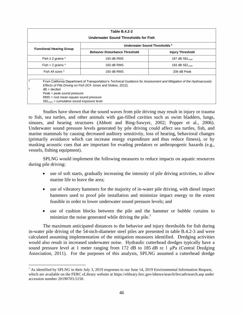
46
Table B.4.2-2
Underwater Sound Thresholds for Fish
Functional Hearing Group Underwater Sound Thresholds b
Behavior Disturbance Threshold Injury Threshold
Fish ≥ 2 grams a 150 dB RMS 187 dB SELcum
Fish < 2 grams a 150 dB RMS 183 dB SELcum
Fish All sizes a 150 dB RMS 206 dB Peak
____________________ a From California Department of Transportation’s Technical Guidance for Assessment and Mitigation of the Hydroacoustic
Effects of Pile Driving on Fish (ICF Jones and Stokes, 2012). b dB = decibel
Peak = peak sound pressure
RMS = root mean-square sound pressure
SELcum = cumulative sound exposure level
Studies have shown that the sound waves from pile driving may result in injury or trauma
to fish, sea turtles, and other animals with gas-filled cavities such as swim bladders, lungs,
sinuses, and hearing structures (Abbott and Bing-Sawyer, 2002; Popper et al., 2006).
Underwater sound pressure levels generated by pile driving could affect sea turtles, fish, and
marine mammals by causing decreased auditory sensitivity, loss of hearing, behavioral changes
(primarily avoidance which can increase energy expenditure and thus reduce fitness), or by
masking acoustic cues that are important for evading predators or anthropogenic hazards (e.g.,
vessels, fishing equipment).
SPLNG would implement the following measures to reduce impacts on aquatic resources
during pile driving:
• use of soft starts, gradually increasing the intensity of pile driving activities, to allow
marine life to leave the area;
• use of vibratory hammers for the majority of in-water pile driving, with diesel impact
hammers used to proof pile installation and minimize impact energy to the extent
feasible in order to lower underwater sound pressure levels; and
• use of cushion blocks between the pile and the hammer or bubble curtains to
minimize the noise generated while driving the pile.7
The maximum anticipated distances to the behavior and injury thresholds for fish during
in-water pile driving of the 54-inch-diameter steel piles are presented in table B.4.2-3 and were
calculated assuming implementation of the mitigation measures identified. Dredging activities
would also result in increased underwater noise. Hydraulic cutterhead dredges typically have a
sound pressure level at 1 meter ranging from 172 dB to 185 dB re 1 μPa (Central Dredging
Association, 2011). For the purposes of this analysis, SPLNG assumed a cutterhead dredge
7 As identified by SPLNG in their July 3, 2019 responses to our June 14, 2019 Environmental Information Request,
which are available on the FERC eLibrary website at https://elibrary.ferc.gov/idmws/search/fercadvsearch.asp under
accession number 20190703-5150.

47
would be operating in the soft substrates characteristic of the Project site, with an underwater
sound pressure level of 172 dB re 1 μPa at 1 meter.
Table B.4.2-3
Calculated Distances to Underwater Noise Thresholds from Dredging and Mitigated In-water Pile Driving
Activity Marine Fauna
Distance from Source in which Threshold would be Exceeded a
Injury due to Peak Pressure b
Injury due to Accumulated Sound Exposure (SELcum) c
Behavioral Disturbance
(RMS) d
Impact pile driving Fish ≥ 2 grams
13 feet 1,221 feet
7,065 feet Fish < 2 grams 1,522 feet
Vibratory pile driving Fish ≥ 2 grams
< 1 foot 127 feet
328 feet Fish < 2 grams 772 feet
Dredging Fish ≥ 2 grams
N/A 48 feet
96 feet Fish < 2 grams 89 feet
a Source NMFS, 2018 b Peak = peak sound pressure c SELcum = cumulative sound exposure level d RMS = root mean-square sound pressure
Based on the distances presented in table B.4.2-3, the in-water pile driving and dredging
could result in injury and behavior disturbance to fish species (and other aquatic species
including marine mammals) that remain in the Project area after the soft-starts. To ensure that
actual underwater noise from pile driving is not significantly greater than predicted noise and
that impacts on fish and other aquatic species is appropriately minimized, SPLNG committed to
perform underwater sound level measurements during the initial in-water test piling phase.
Sound levels would be measured at appropriate distances during the initial test piling to quantify
the underwater sound levels due to the pile driving. SPLNG would then compare the sound
levels used in the underwater noise evaluation to ensure that they are consistent with the
anticipated levels. SPLNG has not committed to providing the results of the underwater sound
levels measured during the initial test piling to FERC or the NMFS. Therefore, we recommend
that:
• Following the completion of the initial in-water test piling phase and prior to
initiating construction pile driving activities, SPLNG should file with the Secretary
of the Commission (Secretary), for review and approval of the Director of the Office
of Energy Projects (OEP), the results of its underwater sound level measurements
and any additional mitigation measures that it would implement to reduce noise to
predicted levels. The test results and any associated mitigation should also be filed
with the NMFS.
Through the implementation of the proposed mitigation measures as well as our
recommendation, we conclude that impacts on fish from pile driving would not be significant.
48
Spills
During construction and operation, hazardous materials resulting from spills or leaks
could have adverse impacts on aquatic resources. Impacts from hazardous materials would be
caused by either the physical nature of the material (e.g., physical contamination and smothering)
or by its chemical components (e.g., toxic effects and bioaccumulation). These impacts would
depend on the depth and volume of the spill, as well as the properties of the material spilled. To
prevent spills and leaks, SPLNG would implement its Project-specific SPCC Plan during
construction and SPC-SPCC Plan during operation, which outline potential sources of releases at
the site, measures to prevent a release, and initial responses in the event of a spill. Increased
vessel traffic during construction and operation of the Project would also result in an increased
potential for spills of hazardous materials; however, all ships are required to maintain a
Shipboard Oil Pollution Emergency Plan (SOPEP) to minimize impacts on aquatic resources.
Given the impact minimization and mitigation measures described above, we conclude that the
probability of a spill of hazardous materials is small and any resulting impacts on aquatic
resources would be temporary and not significant.
Hydrostatic Test Water
Hydrostatic testing for the project is proposed for firewater, wastewater/storm sewer lines
and potable/utility water lines. A total of approximately 40,000 gallons of water would be used
for hydrostatic testing. Water supplied by the SPLNG Terminal’s existing waterline would be
the source water used for dust suppression during construction.
Hydrostatic test water would be discharged over an eight-month period to the existing
stormwater management system and not to existing surface waters. No chemicals would be
added to the hydrostatic test water before or after testing, and the discharge would be tested for
total suspended solids, oil and grease, and pH prior to discharge in accordance with the LPDES
Hydrostatic Test Wastewater Discharge Permit requirements; therefore, no adverse impacts on
aquatic resources from hydrostatic testing would be anticipated.
Lighting
For safety and security purposes, the marine facilities at the Third Berth would require
additional lighting. To avoid attracting aquatic species that rely on light for movement and
feeding patterns, SPLNG would minimize over-water lighting to the extent necessary to carry out
marine operations. Lighting for the Third Berth would be similar to approved lighting currently
in place for the existing SPLNG Terminal marine berths and other marine facilities in the area.
Therefore, we conclude that impacts on aquatic resources from lighting would not be significant.
Vessel Traffic
Potential impacts on aquatic resources resulting from increased vessel traffic include
shoreline erosion and resuspension of sediments, ballast water discharges, cooling water
discharges, and increased noise levels.

49
Impacts on aquatic resources resulting from shoreline erosion and resuspension of
sediments would primarily be limited to increased turbidity. Impacts on aquatic resources from
increased turbidity would be similar to that discussed for dredging but would be on a smaller
scale. The wake from large vessels transiting the Sabine Pass Channel and the Third Berth could
also result in shoreline erosion. SPLNG would install rock revetment slope protection to prevent
erosion of the shoreline within the Third Berth. The increased potential for shoreline erosion
along the Sabine Pass Channel as LNGCs approach or depart the SPLNG Terminal would be
consistent with the existing ship traffic in the channel and the intended use of the Sabine Pass
Channel. The addition of 180 LNGCs per year would be an incremental increase in the overall
annual ship traffic within the Sabine Pass Channel. Additional information regarding marine
traffic is presented in section B.7.4.2.
Support vessels involved in the general construction activities would include tenders,
barges, and tugs. Typical levels for construction and maintenance ships range from 150 to
180 dB re 1 µPa root mean-square sound pressure (RMS) (Protection of the Marine Environment
of the North-East Atlantic, 2009). SPLNG expects that use of these vessels would be sporadic
with long periods of inactivity, similar to the existing water craft and activities in the channel.
The frequency of LNGCs would increase as a result of the Project and it is anticipated that more
mobile aquatic species would temporarily leave the area. Noise levels from the additional
LNGCs during operation would be consistent with the existing ship traffic calling on the SPLNG
Terminal. In general, underwater noise from construction support vessels and additional LNGCs
would not be expected to cause a significant impact on aquatic resources.
Ballast Water
The effects of ballast water discharges on ambient water quality parameters including
temperature, pH, dissolved oxygen, and salinity are described in section B.3.2.5. Ballast water is
stored below the ship’s hull; as a result, the temperature of the discharged water is not expected
to deviate substantially from ambient water temperature.
Operationally, the LNGCs would be discharging bulk ballast with only two pumps
running at a maximum discharge rate of 6,000 m3/hour (cubic meters per hour)
(1,585,205 gallons/hour). The time to discharge the complete ballast volume would be
approximately 15 hours and would be fully aligned with the loading of the LNGC for stability,
draft and trim purposes. Therefore, the average discharge rate would equate to approximately
4,100 m3/hour (1,083,223 gallons/hour). Ballast water discharges would mix with waters in the
Third Berth and then would be circulated into the waters of the Sabine Pass Channel through
natural river flows and tidal actions.
Ballast discharge could impact water quality, fish, and other aquatic organisms. The
general characteristics of the discharged ballast water would be very similar to that of the water
pumped aboard each LNGC during the mandatory ballast water exchange operation. The
location, weather, and existing tidal/current conditions where this ballast water exchange would
take place would determine the unique characteristics of the ballast seawater aboard each LNG
carrier upon its arrival at the marine berth. Discharge of ballast water could result in temporary
50
and localized changes in salinity, dissolved oxygen, and temperature which could have minor
impacts on aquatic species in the vicinity. Ballast discharge could also result in the introduction
of nonindigenous aquatic species which could also impact fish and other aquatic organisms.
Ballast water would be discharged near the bottom of the Third Berth where dissolved
oxygen levels are generally lower. Depending on the oxygen levels present in both the ballast
and ambient water at the time of discharge, aquatic resources present in the vicinity of the
discharge point could be exposed to dissolved oxygen levels considered unhealthy for aquatic
life. More mobile species such as fish would likely temporarily relocate from the area.
Whereas, less mobile species such as mollusks may experience increased stress or death if
dissolved oxygen levels were to remain low. Changes in salinity and temperature would
similarly be anticipated to return to background levels within proximity of the LNGC. Due to
the quantity of ballast water that would be discharged and the ability of most species to move
over short distances to more suitable conditions, we have determined that the impact of ballast
water on aquatic resources resulting from changes in dissolved oxygen levels, salinity, and
temperature would be localized and not significant.
A primary environmental concern regarding ballast water discharge is the potential for
the introduction of non-native species in the ecosystem. Ballast water may contain a diverse
assemblage of marine organisms that may be non-native to a vessel’s destination port. Non-
native species may threaten to outcompete and exclude native species, which may affect the
overall health of an ecosystem, cause algal blooms and hypoxic conditions, and/or affect all
trophic levels resulting in a decline in biodiversity.
The Coast Guard’s ballast water management regulations (33 CFR 151.2025 and
46 CFR 162) established a standard for the allowable concentration of living organisms in ships’
ballast water discharged into waters of the U.S. The Coast Guard also established engineering
requirements and an approval process for ballast water treatment systems installed on ships. All
ships calling on U.S. ports must either carry out open sea exchange of ballast water or ballast
water treatment, in addition to fouling and sediment management and document these activities
in the ship’s log book. In 2017, the International Convention for the Control and Management of
Ships’ Ballast Water and Sediments developed measures that must be implemented to minimize
the potential for introduction of non-native species through ballast water. These measures have
since been adopted by the International Maritime Organization and are required to be
implemented in all ships engaged in international trade. While the open sea exchange of ballast
water has been used in the past and reduces the potential for non-native species introductions,
on-board ballast water treatment systems are more effective at removing potential non-native
species from ballast water. There are two different standards that ships must meet. All new
ships must meet the “D-2” performance standard, which establishes the maximum number of
viable organisms allowed to be discharged in ballast water. Conformity with the D-2 standard
requires ships to utilize on-board ballast water treatment systems. Existing ships that do not
currently have on-board ballast water treatment systems must continue to, at a minimum,
conduct open sea exchanges of ballast water (“D-1” standard). Eventually, all ships will be
required to conform with the D-2 standard. The timetable for conformity with the D-2 standard

51
for existing ships is based on the date of the ship’s International Oil Pollution Prevention
Certificate renewal survey, which occurs every five years (International Maritime
Organization, 2017). Therefore, most ships calling on the Project, estimated to begin in 2023 at
the earliest, would be expected to have conformed to D-2 standards.
Ships are required to keep logs documenting their open water ballast exchanges or ballast
water treatment to comply with the Coast Guard’s regulations. With the implementation of these
mandatory practices required by the Coast Guard and the International Maritime Organization,
we conclude that impacts on aquatic resources as a result of the potential introduction of
non-native species through ballast water discharge would be negligible.
Cooling Water
While at the marine berth, ship cooling water would be withdrawn and discharged below
the water line on the sides of the ship through screened water ports, also known as “sea chests.”
Water intakes would result in the impingement and entrainment of small fish and
ichthyoplankton (fish larvae and eggs). While screens on the sea chests would minimize these
impacts, it is anticipated that most of the entrained or impinged organisms would not survive.
The Third Berth would be sized to accommodate LNGCs that range in capacity from
125,000 m3 to 180,000 m3. LNGCs calling at the SPLNG Terminal would include steam turbine,
dual fuel diesel electric propulsion, and M-type electronically controlled gas injection (MEGI)
type vessels. While at the berth, the LNGCs would not require engines to be run at full power.
Therefore, proportionately less cooling water would be required during loading than while the
LNGC is under way. During maneuvering and while berthed, cooling water would be circulated
through the LNGC at an average flow rate of 3,000 m3/hr (792,516 gallons/hr). The volume of
water discharged by LNGCs would be relatively small compared to the total volume of water
within the Third Berth. Approximately 60,000 m3 (15,850,323 gallons) of seawater would be
transferred at the Third Berth per vessel per visit, which would equal approximately 2.5 percent
of the total Third Berth volume.
Cooling water return temperatures can vary widely depending on the type of LNGC and
mode of operation. Cooling water discharged at the Project berth while in port-mode could
range from between 1.5 degrees Celsius (ºC) and 4.3 degrees C greater than ambient
temperatures (Caterpillar, 2007; 2011; 2012). However, cooling water discharges modeled for a
proposed LNG facility in Warrenton, Oregon, using a more conservative estimate for
temperature of discharge water (6 – 9 ºC above ambient) found that discharge water from
213,000 m3 capacity vessels raised the temperature of the receiving water by 0.3 ºC at a distance
of 4.2 to 5.6 meters from the discharge port. At 14 to 21 meters from the discharge port the
cooling water/receiving water mixture cooled to 0.14 ºC above ambient temperature. The mixing
time for the cooling water/receiving water mixture to achieve 0.14 ºC above ambient temperature
was approximately 15 to 30 seconds (Oregon LNG, 2008).
Due to the relatively small temperature differences and the relatively small volume of
discharge compared to the total water within the Sabine Pass Channel, any discharged cooling

52
water that is warmer than the ambient water would diminish shortly after discharge and would
not be anticipated to significantly impact aquatic resources.
4.3 Essential Fish Habitat
The Magnuson-Stevens Fisheries Conservation and Management Act (MSA) (Public
Law 94-265, as amended through October 11, 1996) was established, along with other goals, to
promote the protection of Essential Fish Habitat (EFH) during the review of projects to be
conducted under federal permits and licenses, or other authorities that affect or have the potential
to affect such habitat. EFH is defined in the MSA as those waters and substrates necessary to
fish for spawning, breeding, feeding, or growth to maturity. Federal agencies that authorize,
fund, or undertake activities that may adversely affect EFH must consult with NMFS.
Although absolute criteria have not been established for conducting EFH consultations,
NMFS recommends consolidated EFH consultations with interagency coordination procedures
required by other statutes, such as NEPA, the Fish and Wildlife Coordination Act, and the ESA,
to reduce duplication and improve efficiency (50 CFR 600.920(e)). Generally, the EFH
consultation process includes the following steps:
1. Notification – The action agency should clearly state the process being used for
EFH consultations (e.g., incorporating EFH consultation into an EA or EIS).
2. EFH Assessment – The action agency should prepare an EFH Assessment that
includes both identification of affected EFH and an assessment of impacts.
Specifically, the EFH Assessment should include:
• a description of the proposed action;
• an analysis of the effects (including cumulative effects) of the proposed action
on EFH, managed fish species, and major prey species;
• the federal agency’s views regarding the effects of the action on EFH; and
• proposed mitigation, if applicable.
3. EFH Conservation Recommendations – After reviewing the EFH Assessment,
NMFS should provide recommendations to the action agency regarding measures
that can be taken by that agency to conserve EFH.
4. Agency Response – Within 30 days of receiving the recommendations, the action
agency must respond to NMFS. The action agency may notify NMFS that a full
response to the conservation recommendations would be provided by a specified
completion date agreeable to all parties. The response must include a description
of measures proposed by the agency to avoid, mitigate, or offset the impact of the
activity on EFH. For any conservation recommendation that is not adopted, the
action agency must explain its reason to NMFS for not following the
recommendation.

53
Specific habitats include all estuarine water and substrate (mud, sand, shell and rock) and
all associated biological communities, such as sub-tidal vegetation (seagrasses and algae) and the
adjacent inter-tidal vegetation (marshes and mangroves). EFH represents areas of high economic
importance due to the dependence of recreational and commercial fisheries directly and
indirectly associated with these areas. Of the fish species considered by NMFS to potentially
occur within the Project area, EFH habitat for these species consists of tidally influenced waters
(estuarine water column) and tidally influenced marsh. SPLNG consulted with NMFS on
July 11, 2018 regarding species and life stages with EFH in the Project area. Table B.4.3-1
provides a list of managed EFH species in the Project area, habitat preference, and life stage
when they may be expected to occur.
Table B.4.3-1
Managed EFH Species Likely to Occur in the Project Area
Species Life Stage Habitat Type
Common Name Scientific Name Juvenile Adult
White shrimp Litopenaeus setiferus X Estuarine emergent wetlands, soft
bottom
Brown shrimp Farfantepenaeus
aztecus X
Estuarine emergent wetlands, soft
bottom
Gray snapper Lutjanus griseus X Estuarine emergent wetlands, soft
bottom
Lane snapper Lutjanus synagris X Soft bottom
Red drum Sciaenops ocellatus X X Estuarine emergent wetlands, soft
bottom
Spanish mackerel Scomberomorus
maculates X X
Estuarine emergent wetlands, soft
bottom
As described in section B.4.2.2, construction of the Project would result in temporary
increases in noise, turbidity, and sedimentation within the estuarine water column. Impacts on
managed species during construction and operation of the Project would be similar to those
described above for aquatic resources (see section B.4.2.2). Construction of the Project would
result in the permanent conversion of 26.8 acres existing estuarine emergent wetland EFH to soft
bottom EFH. In addition, 49.2 acres of existing soft bottom EFH (within the Sabine Pass
Channel) would be temporarily disturbed and deepened; however, following the completion of
the Project this area would continue to serve as soft bottom EFH. SPLNG would mitigate
impacts on estuarine emergent wetlands through beneficial use.
Dredging activities would result in the removal of the existing mud substrates, in turn
removing the existing benthic community. In addition, sediments resuspended in the water
column during dredging and other construction activities would be redeposited on nearby
substrates, potentially smothering immobile fish eggs and larvae as well as benthic invertebrates.
Dredging activities could also cause mortality of larval and juvenile shrimp as well as fish
species in the immediate vicinity of the cutterhead of the dredge. Impacts on soft bottom habitat
would be greatest if dredging occurs during a period of peak larval abundance in early spring or
summer. Increased turbidity associated with dredging would also impact the estuarine water

54
column, temporarily reducing habitat quality through localized increases in suspended sediment
and nutrient levels and decreases in dissolved oxygen. These impacts are anticipated to be short-
term but could have localized effects on movement and foraging of managed fish species within
the estuarine water column habitat.
Ship traffic associated with construction and operation of the Project could affect the
estuarine water column within the Sabine Pass Channel and the Third Berth. Impacts on water
quality may occur due to resuspension of suspended solids, discharge of ballast water, and intake
and discharge of cooling water. However, the Sabine Pass Channel was specifically created to
provide deep water access for maritime commerce and support high levels of deep draft ship
traffic. Therefore, impacts on the estuarine water column as a result of increased ship traffic are
not anticipated to be significant.
In addition to the initial dredging within the Third Berth, SPLNG would also conduct
periodic maintenance dredging of the maneuvering basin. SPLNG anticipates that maintenance
dredging would be necessary every year. Impacts on EFH as a result of maintenance dredging
would be similar to that discussed above for the initial dredging activities associated with the
Project and would not result in a change in EFH type. Therefore, impacts on EFH as a result of
maintenance dredging would not be significant.
4.4 Migratory Birds
Migratory birds follow broad routes called flyways between breeding grounds in the
north and wintering grounds in the tropical regions of Mexico, Central and South America, and
the Caribbean for the non-breeding season. Some species migrate from breeding areas in the
north to the Gulf Coast for the non-breeding season. The proposed Project site is on the border
of the Central Flyway and the Mississippi Flyway, an important pathway for migratory birds,
with many coastal and marine species using the coastlines of Louisiana and Texas during
migration (FWS, 2019). The vegetation communities within the Project area provide potential
habitat for a wide variety of migratory bird species including songbirds, waterbirds, and raptors.
Migratory birds are federally protected under the MBTA. The MBTA (16 USC 703-711) as
amended, implements protections for many native migratory game and non-game birds, with
exceptions for the control of species that cause damage to agricultural or other interests. The
MBTA prohibits the take of any migratory bird or their parts, nest, and eggs, where “take” means
to “pursue, hunt, shoot, wound, kill, trap, capture, or collect.” In addition to the MBTA, the Bald
and Golden Eagle Protection Act provides additional protection to bald and golden eagles. Bald
eagles could occur in the Project area year-round. While suitable foraging habitat is available in
and around the Project site, no suitable nesting habitat is present.
Executive Order 13186 requires all federal agencies undertaking activities that may
negatively affect migratory birds to take a prescribed set of actions to further implement the
MBTA, and directs federal agencies to develop a memorandum of understanding with the FWS
that promotes the conservation of migratory birds. FERC entered into a MOU with the FWS in
March 2011 (MOU-FWS). The focus of the MOU-FWS is on avoiding or minimizing adverse
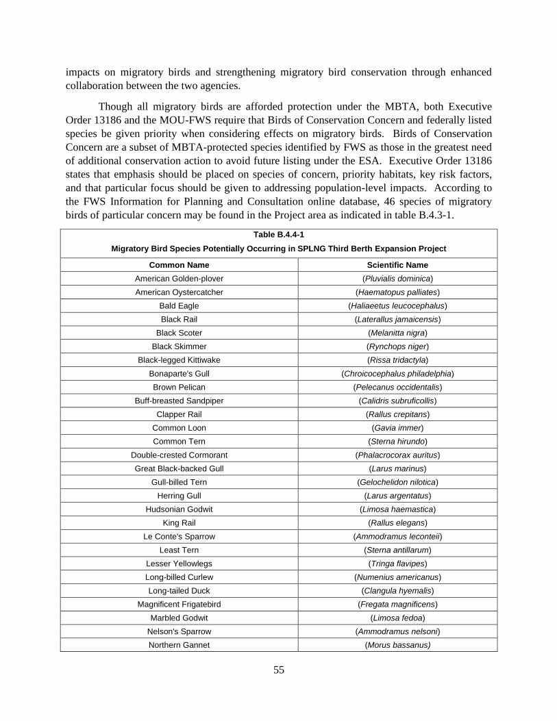
55
impacts on migratory birds and strengthening migratory bird conservation through enhanced
collaboration between the two agencies.
Though all migratory birds are afforded protection under the MBTA, both Executive
Order 13186 and the MOU-FWS require that Birds of Conservation Concern and federally listed
species be given priority when considering effects on migratory birds. Birds of Conservation
Concern are a subset of MBTA-protected species identified by FWS as those in the greatest need
of additional conservation action to avoid future listing under the ESA. Executive Order 13186
states that emphasis should be placed on species of concern, priority habitats, key risk factors,
and that particular focus should be given to addressing population-level impacts. According to
the FWS Information for Planning and Consultation online database, 46 species of migratory
birds of particular concern may be found in the Project area as indicated in table B.4.3-1.
Table B.4.4-1
Migratory Bird Species Potentially Occurring in SPLNG Third Berth Expansion Project
Common Name Scientific Name
American Golden-plover (Pluvialis dominica)
American Oystercatcher (Haematopus palliates)
Bald Eagle (Haliaeetus leucocephalus)
Black Rail (Laterallus jamaicensis)
Black Scoter (Melanitta nigra)
Black Skimmer (Rynchops niger)
Black-legged Kittiwake (Rissa tridactyla)
Bonaparte's Gull (Chroicocephalus philadelphia)
Brown Pelican (Pelecanus occidentalis)
Buff-breasted Sandpiper (Calidris subruficollis)
Clapper Rail (Rallus crepitans)
Common Loon (Gavia immer)
Common Tern (Sterna hirundo)
Double-crested Cormorant (Phalacrocorax auritus)
Great Black-backed Gull (Larus marinus)
Gull-billed Tern (Gelochelidon nilotica)
Herring Gull (Larus argentatus)
Hudsonian Godwit (Limosa haemastica)
King Rail (Rallus elegans)
Le Conte's Sparrow (Ammodramus leconteii)
Least Tern (Sterna antillarum)
Lesser Yellowlegs (Tringa flavipes)
Long-billed Curlew (Numenius americanus)
Long-tailed Duck (Clangula hyemalis)
Magnificent Frigatebird (Fregata magnificens)
Marbled Godwit (Limosa fedoa)
Nelson's Sparrow (Ammodramus nelsoni)
Northern Gannet (Morus bassanus)

56
Table B.4.4-1
Migratory Bird Species Potentially Occurring in SPLNG Third Berth Expansion Project
Common Name Scientific Name
Parasitic Jaeger (Stercorarius parasiticus)
Pomarine Jaeger (Stercorarius pomarinus)
Prothonotary Warbler (Protonotaria citrea)
Red-breasted Merganser (Mergus serrator)
Reddish Egret (Egretta rufescens)
Ring-billed Gull (Larus delawarensis)
Royal Tern (Thalasseus maximus)
Seaside Sparrow (Ammodramus maritimus)
Semipalmated Sandpiper (Calidris pusilla)
Short-billed Dowitcher (Limnodromus griseus)
Sprague's Pipit (Anthus spragueii)
Surf Scoter (Melanitta perspicillata)
Swallow-tailed Kite (Elanoides forficatus)
Whimbrel (Numenius phaeopus)
White-winged Scoter (Melanitta fusca)
Willet (Tringa semipalmata)
Wilson's Plover (Charadrius wilsonia)
Yellow Rail (Coturnicops noveboracensis)
Source: FWS, 2018a
Colonial waterbirds, a subset of migratory birds, generally share two common
characteristics: 1) they tend to gather in large assemblies, called colonies or rookeries, during the
nesting season; and 2) they obtain all or most of their food from the water (FWS, 2002).8 No
colonial waterbird rookeries have been identified in the Project area. In a letter dated May 15,
2018, the FWS recommended that SPLNG survey the Project area prior to commencing
construction activities to ensure that no rookeries are present. If rookeries are present in the
Project area, the FWS recommended that SPLNG maintain buffers around the rookeries ranging
from 650 feet to 1,000 feet, depending on the species and train Project personnel in the
identification of colonial nesting birds and their nests. We requested that SPLNG commit to
implementing the measures recommended by FWS. To date, SPLNG has not committed to
implementing these measures. Therefore, we recommend that:
• Prior to construction, SPLNG should file with the Secretary documentation of
correspondence with the FWS regarding the results of pre-construction rookery
surveys and measures that SPLNG would implement in the event that rookeries are
8 Colonial waterbirds demonstrate nest fidelity, meaning that they return to the same rookery year after
year. Rookeries are typically established in marshes or near the shores of ponds or streams. Although some colonial
waterbirds (e.g., least terns) will nest in developed areas, many waterbirds (e.g., great blue heron and great egrets)
are wary of human activity.

57
identified within the Project area, for review and written approval by the Director
of OEP.
Habitat for migratory birds exists within a wide range of conditions adjacent to the
SPLNG Terminal, including marsh, coastal areas, and woodlands; however, the Project would
impact only a small area of marsh habitat adjacent to the existing marine berth. Construction and
operation of the Third Berth would not be anticipated to affect migratory birds in the area due to
the relatively minor impacts on undisturbed terrestrial habitat. Previous comments from FWS
regarding impacts on migratory birds at the SPLNG Terminal expressed concerns with regard to
the effects of “lighting, communication, and/or flare towers associated with the operation of the
LNG terminal…” Lighting for the Third Berth would be consistent with the previously approved
lighting at the existing berth at the SPLNG Terminal, and no communications towers or
additional flares are proposed as part of the Project. Birds in the area have either become
acclimated to activities at the SPLNG Terminal or would avoid it. SPLNG correspondence with
FWS via email on June 21, 2018 concluded no suitable nesting habitat occurs in the Project area.
No issues have been identified with the proposed facilities and no additional mitigation has been
recommended. Therefore, we conclude that the Project would not result in significant impacts
on migratory birds.
4.5 Special Status, Threatened, and Endangered
Federal agencies are required under Section 7 of ESA, as amended, to ensure that any
actions authorized, funded, or carried out by the agency would not jeopardize the continued
existence of a federally listed endangered or threatened species, or result in the destruction or
adverse modification of the designated critical habitat of a federally listed species.
As the lead federal agency authorizing the Project, FERC is required to consult with the
FWS and/or NMFS, to determine whether federally listed threatened or endangered species or
designated critical habitat are found in the vicinity of the Project, and to evaluate the proposed
action’s potential effects on those species or critical habitats. In accordance with
Section 380.13(b) of FERC’s Order 603, however, the project sponsor is designated as FERC’s
non-federal representative for purposes of initial coordination and informal consultation with the
FWS and the NMFS. In compliance with ESA, SPLNG has been assisting FERC in meeting its
Section 7 obligations by conducting informal consultations with the FWS and NMFS about
species under their jurisdictions that would be potentially affected by the Projects. In addition,
SPLNG also consulted with TPWD, LDWF, and reviewed publicly available resources.
4.5.1 Federally Listed Species
Sixteen species are federally listed as threatened or endangered (T&E) with potential to
occur in the proposed Project area, including three birds, one fish, five marine reptiles, five
marine mammals, one shark, and one ray (see table B.3.4-1). Impacts on T&E species were
assessed for the Project site as well as the proposed placement of dredge material for mitigation
at the Louisiana Point DMPA. The listed fish species, the Gulf sturgeon, is not known to occur
west of the Mississippi River. As a result, we have determined that the Project would have no
58
effect on Gulf sturgeon and this species is not discussed further. In addition, the oceanic whitetip
shark would occur only along the LNGC transit routes. This species does not spend time at the
surface, minimizing the potential for vessel strikes. Therefore, we have determined that the
Project would have no effect on the oceanic whitetip shark and this species is not discussed
further.
SPLNG would utilize EIs during all phases of construction. The EIs would be trained to
identify T&E species. In addition, all construction staff would receive general environmental
training that would include awareness of the potential for T&E species thought to occur in the
area. If any T&E species were observed in the immediate Project area during active
construction, the EIs, along with the SPLNG environmental leads, would determine if there was
a need for any special avoidance or minimization measures. The EIs also have stop work
authority in the instance of T&E occurrence.
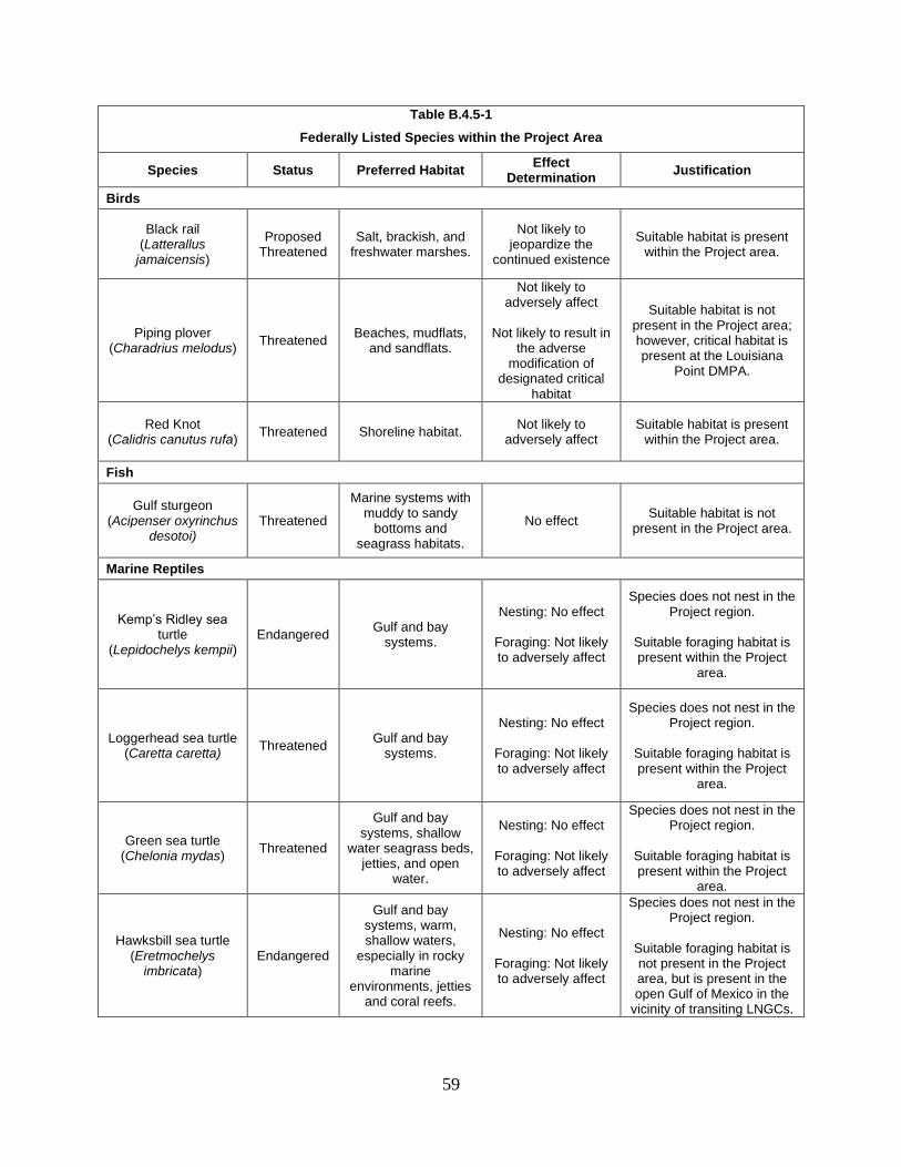
59
Table B.4.5-1
Federally Listed Species within the Project Area
Species Status Preferred Habitat Effect
Determination Justification
Birds
Black rail (Latterallus
jamaicensis)
Proposed Threatened
Salt, brackish, and freshwater marshes.
Not likely to jeopardize the
continued existence
Suitable habitat is present within the Project area.
Piping plover (Charadrius melodus)
Threatened Beaches, mudflats,
and sandflats.
Not likely to adversely affect
Not likely to result in
the adverse modification of
designated critical habitat
Suitable habitat is not present in the Project area; however, critical habitat is present at the Louisiana
Point DMPA.
Red Knot (Calidris canutus rufa)
Threatened Shoreline habitat. Not likely to
adversely affect Suitable habitat is present
within the Project area.
Fish
Gulf sturgeon (Acipenser oxyrinchus
desotoi) Threatened
Marine systems with muddy to sandy
bottoms and seagrass habitats.
No effect Suitable habitat is not
present in the Project area.
Marine Reptiles
Kemp’s Ridley sea turtle
(Lepidochelys kempii) Endangered
Gulf and bay systems.
Nesting: No effect
Foraging: Not likely to adversely affect
Species does not nest in the Project region.
Suitable foraging habitat is present within the Project
area.
Loggerhead sea turtle (Caretta caretta)
Threatened Gulf and bay
systems.
Nesting: No effect
Foraging: Not likely to adversely affect
Species does not nest in the Project region.
Suitable foraging habitat is present within the Project
area.
Green sea turtle (Chelonia mydas)
Threatened
Gulf and bay systems, shallow
water seagrass beds, jetties, and open
water.
Nesting: No effect
Foraging: Not likely to adversely affect
Species does not nest in the Project region.
Suitable foraging habitat is present within the Project
area.
Hawksbill sea turtle (Eretmochelys
imbricata) Endangered
Gulf and bay systems, warm, shallow waters,
especially in rocky marine
environments, jetties and coral reefs.
Nesting: No effect
Foraging: Not likely to adversely affect
Species does not nest in the Project region.
Suitable foraging habitat is not present in the Project area, but is present in the open Gulf of Mexico in the
vicinity of transiting LNGCs.

60
Table B.4.5-1
Federally Listed Species within the Project Area
Species Status Preferred Habitat Effect
Determination Justification
Leatherback sea turtle (Dermochelys
coriacea) Endangered
Gulf and bay systems.
Nesting: No effect
Foraging: Not likely to adversely affect
Species does not nest in the Project region.
Suitable foraging habitat is not present in the Project area, but is present in the open Gulf of Mexico in the
vicinity of transiting LNGCs.
Marine Mammals
West Indian manatee (Trichechus manatus)
Threatened
Occasional visitor to Texas/ Louisiana waters. Inhabits warm, shallow coastal waters, estuaries, bays,
rivers, and lakes.
Not likely to adversely affect
Suitable habitat is present within the Project area.
Fin Whale (Balaenoptera
physalus) Endangered
Deep waters of the continental shelf.
Not likely to adversely affect
Suitable habitat is not present in the Project area, but is present in the open
Gulf of Mexico in the vicinity of transiting LNGCs.
Sei Whale (Balaenoptera
borealis) Endangered
Deep waters of the continental shelf.
Not likely to adversely affect
Suitable habitat is not present in the Project area, but is present in the open
Gulf of Mexico in the vicinity of transiting LNGCs.
Sperm Whale (Physeter
macrocephalus) Endangered
Deep waters of the continental shelf.
Not likely to adversely affect
Suitable habitat is not present in the Project area, but is present in the open
Gulf of Mexico in the vicinity of transiting LNGCs.
Gulf of Mexico Bryde’s Whale (Balaenoptera
edeni)
Proposed Endangered
Deep waters of the continental shelf.
Not likely to adversely affect
Suitable habitat is not present in the Project area, but is present in the open
Gulf of Mexico in the vicinity of transiting LNGCs.
Sharks and Rays
Oceanic Whitetip Shark
(Carcharhinus longimanus)
Threatened
Tropical and subtropical open ocean with water
depths greater than 600 feet.
No effect
Species occurs within the Gulf of Mexico; however, it does not spend time at the
surface, minimizing the potential for vessel strikes.
Giant Manta Ray (Manata birostris)
Threatened
Tropical, subtropical, and temperate
oceanic waters near productive coastlines.
Not likely to adversely affect
Suitable habitat is not present in the Project area, but is present in the open
Gulf of Mexico in the vicinity of transiting LNGCs.

61
Table B.4.5-1
Federally Listed Species within the Project Area
Species Status Preferred Habitat Effect
Determination Justification
Source: FWS, 2018a; NMFS, 2019a; 2019b; 2019c; LDWF, 2018a; TPWD, 2018
Birds
Black Rail
The black rail was proposed for listing by the USFWS as a threatened species under the
ESA on October 9, 2018. One of four species of black rail, the eastern black rail lives in salt,
brackish, and freshwater marshes in as many as 36 states, in addition to multiple territories and
countries in Central and South America. Primary threats to the eastern black rail include habitat
loss due to continued alteration and loss of wetland habitats, land management practices that
result in fire suppression (or inappropriately timed fire application that may cause direct
mortalities), grazing, haying and mowing, and impounding of wetlands (FWS, 2018b). The
USFWS is proposing a rule under the ESAs Section 4(d) that would tailor protections for the
eastern black rail. These protections include prohibiting certain activities in known eastern black
rail habitat during critical time periods, such as nesting and brooding seasons, and post-breeding
flightless molt periods.
Suitable habitat for the black rail is present within affected estuarine wetlands. In
addition, FWS recommended that SPLNG conduct Project activities within black rail habitat
outside of the breeding and flightless molt periods (i.e., mid-March through September) to the
greatest extent possible. We requested that SPLNG commit to implementing the FWS
recommendations. To date, SPLNG has not committed to implementing these recommendations,
nor have they provided documentation of correspondence with the FWS regarding alternative
measures that could be implemented to minimize impacts on black rails. Therefore, we
recommend that:
• Prior to construction, SPLNG should file with the Secretary, for review and
written approval by the Director of OEP, measures that it would implement
to minimize impacts on the black rail. SPLNG should also file
documentation of correspondence with the FWS regarding these measures.
With the implementation of our recommendation, as well as SPLNG’s required
mitigation of wetlands (black rail habitat), we have determined that the Project is not likely to
jeopardize the continued existence of the black rail.
Red Knot
Red knots nests in the far north, well above the Arctic Circle and its winter range
includes shorelines around the world, south to Australia and southern South America. Outside of
breeding season, it is found primarily in intertidal, marine habitats, especially near coastal inlets,
estuaries, and bays. Its diet includes mollusks, insects, green vegetation, and seeds. In migration

62
and winter, the red knot feeds on small invertebrates that live in the mud of the intertidal zone,
especially small mollusks, marine worms, and crustaceans. On dry sand and its tundra breeding
grounds, the red knot forages by sight, picking items from the ground surface. On tidal flats, it
forages by probing the mud with its bill, finding food items by touch (National Audubon
Society, 2018a). The red knot is federally listed as threatened under the ESA. The red knot may
be found in the Project area during spring and fall migrations (April-May and September-
October), but it prefers shoreline habitats. No suitable habitat is present in the Project area;
however, suitable habitat is present within the Louisiana Point DMPA. As the dredge material
placed in the Louisiana Point DMPA would be utilized to create and enhance red knot habitat,
we have determined that the Project is not likely to adversely affect the red knot. No designated
critical habitat for the red knot would be impacted by the Project.
Piping Plover
The piping plover is listed as threatened. Shorebird hunting during the early 1900s
caused the first known major decline of piping plovers (Bent, 1929). Since then, loss or
modification of habitat resulting from commercial, residential, and recreational developments,
dune stabilization, damming and channelization of rivers (eliminating sandbars, encroachment of
vegetation, and altering water flows), and wetland drainage have further contributed to the
decline of the species. Additional threats include human disturbances through recreational use of
habitat, and predation of eggs. Piping plovers typically inhabit shorelines of oceans, rivers, and
inland lakes. Nest sites include sandy beaches, especially where scattered tufts of grass are
present; sandbars; causeways; bare areas on dredge-created and natural alluvial islands in rivers;
gravel pits along rivers; silty flats and salt-encrusted bare areas of sand, gravel, or pebbly mud on
interior alkali lakes and ponds. On the wintering grounds, these birds use beaches, mudflats,
sandflats, dunes, and off-shore spoil islands.
No suitable habitat is present in the Project area; however, suitable habitat is present
within the Louisiana Point DMPA. As the dredge material placed in the Louisiana Point DMPA
would be utilized to create and enhance red knot habitat, we have determined that the Project is
not likely to adversely affect the piping plover.
Designated critical habitat (wintering) for the piping plover is present at the Louisiana
Point DMPA. SPLNG consulted with FWS regarding the potential impacts of dredge material
placement on piping plover critical habitat on July 5, 2018. FWS indicated that the placement of
dredge material to create and/or enhance piping plover habitat was acceptable. Therefore, we
conclude that the Project would result in no adverse modification of designated critical habitat
for piping plovers.
Marine Reptiles
The FWS and NMFS share jurisdiction under the ESA for sea turtles; the FWS has
jurisdiction over sea turtles on land (terrestrial habitat) and the NMFS has jurisdiction over sea
turtles in marine and estuarine waters. Sea turtles are almost exclusively aquatic (occurring
within marine and estuarine waters), with terrestrial habitat use only occurring when adult
females come to shore to lay eggs.

63
Kemp’s Ridley Sea Turtle
Kemp’s Ridley sea turtles are federally listed as endangered. Although it does not nest in
Louisiana, the estuarine and offshore waters of Louisiana are considered important foraging
areas for this species and they have been documented in Sabine Lake (FWS, 2018c). During the
non-breeding season, Kemp’s Ridley sea turtles prefer warm bays, shallow coastal waters, tidal
rivers, estuaries, and seagrass beds (LDWF, 2018b) with substrates of sand and mud
(FWS, 2018c). Juvenile Kemp’s ridley sea turtles are generally found in Louisiana’s coastal
waters from May through October, whereas adults are common during the spring and summer
near the mouth of the Mississippi River. In the winter, Kemp’s ridley sea turtles typically move
offshore to deeper, warmer waters, but some of the deep-water channels and estuaries in
Louisiana might provide important thermal refuge (LDWF, 2018b). NMFS identified April and
May as months when Kemp’s ridley sea turtles are believed to be most abundant at the SPLNG
Terminal (NMFS, 2004).
Adults are primarily shallow-water benthic feeders that specialize on portunid crabs
(FWS, 2018c). Other food items include shrimp, snails, bivalves, sea urchins, jellyfish, sea stars,
fish, and occasionally marine plants (Pritchard and Marquez, 1973; Georgia Aquarium, 2018).
Juveniles typically feed on Sargassum species and associated infauna (FWS and NMFS, 1992).
Loggerhead Sea Turtle
The loggerhead sea turtle is federally listed as threatened. The loggerhead sea turtle
favors warm temperate and sub-tropical regions (NMFS and FWS, 1991a) and is widely
distributed in tropical and subtropical seas (Rebel, 1974; Ross, 1982). This species typically
occurs over the continental shelf, and in bays, estuaries, lagoons, creeks, and mouths of rivers,
but has been found as far as 500 miles offshore (NMFS and FWS, 1991a). In the continental
U.S., loggerhead sea turtles’ nest along the Atlantic coast from Florida to as far north as New
Jersey (Musick, 1979) and sporadically along the Gulf Coast (NMFS and FWS, 1991a). Nesting
occurs primarily on barrier islands adjacent to continental landmasses in warm-temperate and
sub-tropical waters (NMFS and FWS, 1991a). Nest sites are typically located on open sandy
beaches above the mean high tide and seaward of well-developed dunes.
Adults occupy a variety of habitats, ranging from turbid bays to clear waters of reefs,
whereas subadults occur mainly in nearshore and estuarine waters (NMFS and FWS, 1991a).
Hatchlings move directly to sea after hatching, and often float in masses of sargassum (NMFS
and FWS, 1991a). Loggerhead sea turtles’ diet consists of a wide variety of benthic and pelagic
food items. Crabs and mollusks make up the majority of the adult loggerhead’s diet, although
they will also feed opportunistically on dead fish (Rebel, 1974; Savannah River Ecology
Laboratory, 2018).
The probability of the loggerhead sea turtle nesting in the Project area would be very low
due to a lack of suitable nesting habitat (i.e., sandy beaches). Because loggerhead sea turtles are
known to occur in turbid bays, there is a moderate probability of this species occurring within the
Sabine Lake estuary and, more specifically, the Project site. In addition, loggerhead sea turtles
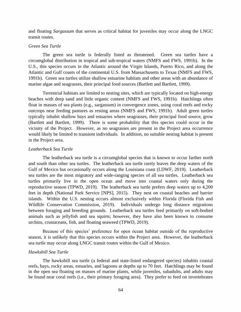
64
and floating Sargassum that serves as critical habitat for juveniles may occur along the LNGC
transit routes.
Green Sea Turtle
The green sea turtle is federally listed as threatened. Green sea turtles have a
circumglobal distribution in tropical and sub-tropical waters (NMFS and FWS, 1991b). In the
U.S., this species occurs in the Atlantic around the Virgin Islands, Puerto Rico, and along the
Atlantic and Gulf coasts of the continental U.S. from Massachusetts to Texas (NMFS and FWS,
1991b). Green sea turtles utilize shallow estuarine habitats and other areas with an abundance of
marine algae and seagrasses, their principal food sources (Bartlett and Bartlett, 1999).
Terrestrial habitats are limited to nesting sites, which are typically located on high-energy
beaches with deep sand and little organic content (NMFS and FWS, 1991b). Hatchlings often
float in masses of sea plants (e.g., sargassum) in convergence zones, using coral reefs and rocky
outcrops near feeding pastures as resting areas (NMFS and FWS, 1991b). Adult green turtles
typically inhabit shallow bays and estuaries where seagrasses, their principal food source, grow
(Bartlett and Bartlett, 1999). There is some probability that this species could occur in the
vicinity of the Project. However, as no seagrasses are present in the Project area occurrence
would likely be limited to transient individuals. In addition, no suitable nesting habitat is present
in the Project area.
Leatherback Sea Turtle
The leatherback sea turtle is a circumglobal species that is known to occur farther north
and south than other sea turtles. The leatherback sea turtle rarely leaves the deep waters of the
Gulf of Mexico but occasionally occurs along the Louisiana coast (LDWF, 2019). Leatherback
sea turtles are the most migratory and wide-ranging species of all sea turtles. Leatherback sea
turtles primarily live in the open ocean and move into coastal waters only during the
reproductive season (TPWD, 2019). The leatherback sea turtle prefers deep waters up to 4,200
feet in depth (National Park Service [NPS], 2015). They nest on coastal beaches and barrier
islands. Within the U.S. nesting occurs almost exclusively within Florida (Florida Fish and
Wildlife Conservation Commission, 2019). Individuals undergo long distance migrations
between foraging and breeding grounds. Leatherback sea turtles feed primarily on soft-bodied
animals such as jellyfish and sea squirts; however, they have also been known to consume
urchins, crustaceans, fish, and floating seaweed (TPWD, 2019).
Because of this species’ preference for open ocean habitat outside of the reproductive
season, it is unlikely that this species occurs within the Project area. However, the leatherback
sea turtle may occur along LNGC transit routes within the Gulf of Mexico.
Hawksbill Sea Turtle
The hawksbill sea turtle (a federal and state-listed endangered species) inhabits coastal
reefs, bays, rocky areas, estuaries, and lagoons at depths up to 70 feet. Hatchlings may be found
in the open sea floating on masses of marine plants, while juveniles, subadults, and adults may
be found near coral reefs (i.e., their primary foraging area). They prefer to feed on invertebrates

65
such as sponges, mollusks, and sea urchins, although they are omnivorous. Hawksbills come
ashore to nest and prefer undisturbed, deep sand beaches. Preferred beaches may range from
high-energy to small pocket beaches bounded by crevices of cliff walls with woody vegetation
near the waterline (NMFS, 2004; COE, 2003). The greatest threat to this population has been the
harvest of turtles to supply the tortoise shell market and stuffed turtle curios. It is also used to
manufacture leather, oil, perfume, and cosmetics.
Hawksbill sea turtles are circumtropical and occur in the tropical and subtropical areas of
the Atlantic, Pacific, and Indian Oceans. Nesting sites are known along the Yucatan Peninsula of
Mexico, the U.S. Virgin Islands, Puerto Rico, and the Florida Keys. This species is rarely seen
in Louisiana (LDWF, 2004). As such, Hawksbill sea turtles within the Project region, would
primarily be located along the LNGC transit routes.
Conclusion
Due to the potential presence of sea turtles within the Project area and along vessel transit
routes, the Project could directly affect sea turtles as a result of dredging, pile driving, and
LNGC and other marine vessel transit (e.g., construction barges and tugboats). Potential effects
from the Project would primarily be limited to impacts on green, Kemp’s ridley, and loggerhead
turtles because of their more common presence within coastal portions of the Gulf of Mexico.
Potential impacts on sea turtles and measures SPLNG would implement to avoid and minimize
these impacts are described below.
Although unlikely, sea turtles could be injured or killed during dredging activities
through contact with or entrainment in the dredge. The potential for injury of or mortality to sea
turtles as a result of dredging is primarily limited to hopper dredging, which entrain turtles and
other marine species because of the large suction tubes used to extract bottom sediments.
However, sea turtles easily avoid hydraulic cutterhead dredges due to the slow movement of the
dredge (COE, 2013). For this reason, the NMFS recommends the use of non-hopper dredges,
particularly during sea turtle nesting and hatching periods (COE, 2011b).
Another potential impact on sea turtles from dredging could be habitat degradation
through a temporary decrease in water quality during and immediately following dredging
activities. Dredging activities suspend sediments in the water column, creating increased total
suspended solids and turbidity, increased dissolved nutrient levels, and decreased dissolved
oxygen levels within the waters surrounding the dredging activity. The magnitude and spatial
extent of these water quality effects varies widely depending on site conditions (e.g., background
water and sediment quality, tidal exchange) and the dredging method used. Proposed use of a
hydraulic cutterhead dredge would minimize turbidity in the vicinity of the dredge activities
because the turbid water is siphoned into the temporary pipeline along with the substrate.
Installation of 116 in-water piles over 9 months would be necessary for construction of
the Third Berth. Underwater sound pressure levels generated by pile driving could affect sea
turtles by causing decreased auditory sensitivity; loss of hearing; behavioral changes such as
avoidance, which can increase energy expenditure, reducing overall fitness; or by masking
acoustic cues that are important for evading predators or anthropogenic hazards (e.g., vessels,

66
fishing equipment). NMFS has developed guidelines for determining sound pressure level
thresholds for sea turtles (NMFS, 2018). SPLNG utilized these guidelines to determine the
sound pressure level thresholds for sea turtles presented in table B.4.5-2. Avoidance behavior
has been observed in sea turtles in response to seismic signals at levels between 166 and 179 dB
(McCauley et al., 2000).
Table B.4.5-2
Underwater Sound Thresholds for Sea Turtles
Functional Hearing Group
Underwater Sound Thresholds a
Vibratory Pile Driving – Behavioral Disturbance b
Vibratory Pile Driving – Injury
Impact Pile Driving – Behavioral Disturbance b
Impact Pile Driving – Injury
Sea Turtles 166 dB RMS 180 dB RMS 166 dB RMS 180 dB RMS a Source: NMFS, 2018. b The root mean square exposure level is the square root of the average sound pressures over the duration of
a pulse and represents the effective pressure and intensity produced by a sound source.
Although sea turtles would be expected to largely avoid the Project area during pile
driving activities, the potential exists for sea turtles to be injured during the first several strikes of
the pile driving hammer. The distances at which the thresholds presented in table B.4.5-2 would
be expected to occur are presented in table B.4.5-3.
Table B.4.5-3
Calculated Distances to Underwater Noise Thresholds for Sea Turtles from Dredging and Mitigated In-water
Pile Driving
Activity Distance from Source in which Threshold would be Exceeded
Injury (RMS) Behavioral Disturbance (RMS)
Impact pile driving 71 feet 606 feet
Vibratory pile driving 3 feet 28 feet
Dredging 1 foot 8.2 feet
As presented in table B.4.5-3, injury to sea turtles during pile driving would occur within
71 feet and 3 feet for impact and vibratory pile driving, respectively, and within 1 foot during
dredging. These are relatively small impact radii, and it seems unlikely that sea turtles would be
this close to the pile driving activities, especially due to the movement of the tender vessels,
barges, and other activities associated with setting up and preparing for pile driving. However,
behavioral disturbances may occur up to 606 feet from impact pile drivers. SPLNG would
reduce impacts on sea turtles as well as other marine species from pile driving by implementing
the measures outlined in section B.4.2.2 for fish, including soft starts. The distances from pile
driving in which sound thresholds would be exceeded were calculated based on the use of
mitigation measures such as cushion blocks and bubble curtains. Therefore, we have included a
recommendation in section B.4.2.2 to ensure that actual underwater noise levels do not exceed
predicted levels.
Potential impacts on sea turtles resulting from increased vessel transit include injury or
mortality due to vessel strikes, and accidental leaks or spills of hazardous materials. During

67
construction and operation of the Project, barges, support vessels, and LNGCs would call on the
SPLNG Terminal, increasing ship traffic within the Sabine Pass Channel and Gulf of Mexico.
Increased marine traffic could result in collisions with sea turtles. However, SPLNG would
provide ship captains with the NMFS Southeast Region’s Vessel Strike Avoidance Measures and
Reporting for Mariners (2008). As discussed in section B.4.2.2, to minimize the potential for a
spill, leak, or accidental release of hazardous substances, each LNG carrier would maintain a
SOPEP to minimize impacts in the event of a petroleum release.
While sea turtles could occur within the Project area, they are more likely to occur near
Louisiana Point DMPA. SPLNG consulted with NMFS on September 25, 2018 regarding
minimization measures that should be implemented for placement of dredged material within the
Louisiana Point DMPA. NMFS confirmed that, due to the potential presence of Kemp’s ridley
sea turtles in the area during April and May, SPLNG would be required to adhere to a timing
restriction on the use of the DMPA. SPLNG confirmed that they would implement this measure
during dredging.
FERC requested that SPLNG commit to implementing the NMFS 2006 Sea Turtle and
Smalltooth Sawfish Construction Conditions during construction of the Project to further
minimize impacts on sea turtles. SPLNG has not committed to implementing these measures.
Therefore, we recommend that:
• During construction of the Project, SPLNG should implement the measures
outlined in the NMFS 2006 Sea Turtle and Smalltooth Sawfish Construction
Conditions.
As of the writing of this EA, consultations have not been completed with NMFS (see our
recommendation below). Based on the implementation of the mitigation measures outlined
above and our recommendations, we conclude that the Project is not likely to adversely affect sea
turtles in the marine environment. Further, as no suitable nesting habitat occurs in the Project
area and sea turtles are not known to nest in the Project area, we conclude that the Project would
have no effect on nesting sea turtles.
There is potential for vessels to divide floating Sargassum designated as critical habitat
for loggerhead sea turtles in the Gulf of Mexico (Designated Critical Habitat Unit LOGG-S-02).
However, these impacts would be temporary and the Sargassum habitat would continue to serve
as developmental and foraging habitat for loggerhead sea turtles. In addition, LNGC transit
could also result in the accidental release of hazardous materials to Sargassum habitat.
Implementation of the SOPEP would substantially reduce the potential for degradation of
designated critical habitat for loggerhead sea turtles. Therefore, we conclude that the Project
would result in no adverse modification of designated critical habitat for loggerhead sea turtles.
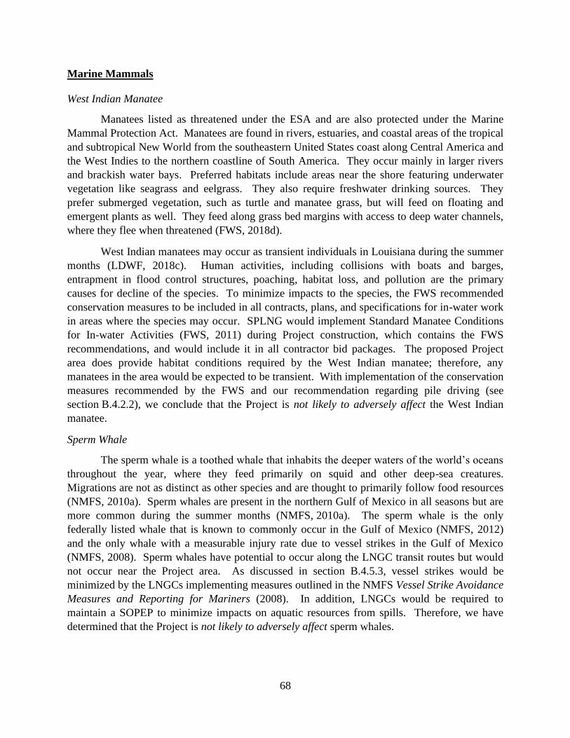
68
Marine Mammals
West Indian Manatee
Manatees listed as threatened under the ESA and are also protected under the Marine
Mammal Protection Act. Manatees are found in rivers, estuaries, and coastal areas of the tropical
and subtropical New World from the southeastern United States coast along Central America and
the West Indies to the northern coastline of South America. They occur mainly in larger rivers
and brackish water bays. Preferred habitats include areas near the shore featuring underwater
vegetation like seagrass and eelgrass. They also require freshwater drinking sources. They
prefer submerged vegetation, such as turtle and manatee grass, but will feed on floating and
emergent plants as well. They feed along grass bed margins with access to deep water channels,
where they flee when threatened (FWS, 2018d).
West Indian manatees may occur as transient individuals in Louisiana during the summer
months (LDWF, 2018c). Human activities, including collisions with boats and barges,
entrapment in flood control structures, poaching, habitat loss, and pollution are the primary
causes for decline of the species. To minimize impacts to the species, the FWS recommended
conservation measures to be included in all contracts, plans, and specifications for in-water work
in areas where the species may occur. SPLNG would implement Standard Manatee Conditions
for In-water Activities (FWS, 2011) during Project construction, which contains the FWS
recommendations, and would include it in all contractor bid packages. The proposed Project
area does provide habitat conditions required by the West Indian manatee; therefore, any
manatees in the area would be expected to be transient. With implementation of the conservation
measures recommended by the FWS and our recommendation regarding pile driving (see
section B.4.2.2), we conclude that the Project is not likely to adversely affect the West Indian
manatee.
Sperm Whale
The sperm whale is a toothed whale that inhabits the deeper waters of the world’s oceans
throughout the year, where they feed primarily on squid and other deep-sea creatures.
Migrations are not as distinct as other species and are thought to primarily follow food resources
(NMFS, 2010a). Sperm whales are present in the northern Gulf of Mexico in all seasons but are
more common during the summer months (NMFS, 2010a). The sperm whale is the only
federally listed whale that is known to commonly occur in the Gulf of Mexico (NMFS, 2012)
and the only whale with a measurable injury rate due to vessel strikes in the Gulf of Mexico
(NMFS, 2008). Sperm whales have potential to occur along the LNGC transit routes but would
not occur near the Project area. As discussed in section B.4.5.3, vessel strikes would be
minimized by the LNGCs implementing measures outlined in the NMFS Vessel Strike Avoidance
Measures and Reporting for Mariners (2008). In addition, LNGCs would be required to
maintain a SOPEP to minimize impacts on aquatic resources from spills. Therefore, we have
determined that the Project is not likely to adversely affect sperm whales.

69
Baleen Whales
Baleen whales, including the fin whale, sei whale, and the Gulf of Mexico Bryde’s whale
that was recently proposed for listing, are listed by NMFS as occurring within the southeast
region. These whales are not commonly found in the Gulf of Mexico but could occur within the
area during migrations or other movements (NMFS, 2012). Feeding is not expected in or around
the Gulf of Mexico as these species usually feed on zooplankton and small fish aggregations
during summer months in the northern Atlantic Ocean (NMFS, 2010b; 2011). Calving and
breeding grounds have not been identified for these species in the Gulf of Mexico. Impacts on
federally listed baleen whales would be minimized through the implementation of measures
similar to those discussed above for the sperm whale. Therefore, we have determined that the
Project is not likely to adversely affect federally listed baleen whales.
Rays
Giant Manta Ray
The giant manta ray was listed as threatened under the Endangered Species Act in 2018.
The giant manta ray occurs worldwide in tropical, subtropical, and temperate oceans. This
species is migratory and seasonally visits productive coastlines in oceanic island groups and near
offshore pinnacles and seamounts to feed on zooplankton and small fish (NMFS, 2019b). Giant
manta rays do not occur in the Sabine Pass Channel, but may be present in the Gulf of Mexico
along the LNGC transit routes. Impacts on giant manta rays would be minimized through the
implementation of measures similar to those discussed above for whales and sea turtles.
Therefore, we have determined that the Project is not likely to adversely affect federally listed
giant manta rays.
Conclusion
A variety of measures have been proposed by SPLNG that would minimize impacts on
federally listed species, including but not limited to, species-specific guidance from FWS and
NMFS, measures to minimize noise from pile driving, use of a cutterhead dredge, timing
restrictions, and implementation of NMFS-issued guidance that outlines collision avoidance
measures to be implemented in order to minimize impacts on marine mammals and sea turtles.
However, because consultations with the FWS and NMFS are ongoing, we recommend that:
• SPLNG should not begin construction activities until:
a. the FERC staff receives comments from the FWS and the NMFS regarding the
proposed action;
a. the FERC staff completes ESA consultation with the FWS and NMFS; and
b. SPLNG has received written notification from the Director of OEP that
construction or use of mitigation may begin.

70
4.5.2 State-listed Species
There are 11 state-listed T&E species identified by either TPWD or LDWF as potentially
occurring in the Project area, 8 of which are also federally listed and discussed in section B.4.5.1.
TPWD also lists the interior least tern and smalltooth sawfish that, while federally listed, do not
occur in the Project region and are not discussed further. In addition to the federally listed
species discussed above, LDWF and TPWD also lists the brown pelican as endangered.
Brown pelicans rely on marine predators such as sharks and dolphins, to force schools of
fish to the surface where they can be caught. They are sensitive to human disturbances and will
breed only in areas with enough food to support the breeding colony. Roosting and resting sites,
where brown pelicans can dry their feathers and rest without disturbance, also are important.
Brown pelicans’ nest in colonies in areas where risk of predation from land predators is low,
usually on isolated islands (Cornell Lab of Ornithology, 2018). They build large bulky nests on
the ground or on island cliffs or low trees, such as mangroves (National Audubon Society,
2018b).
Suitable nesting habitat is not present in the Project area. While brown pelicans may
forage along the Sabine Pass Channel and near the Louisiana Point DMPA, they would likely
avoid the areas during construction activities. As the Project would not result in the loss of
suitable nesting habitat or otherwise adversely impact brown pelicans, we have determined that
impacts on brown pelicans would not be significant.
4.5.3 Marine Mammals
SPLNG would conduct in-water pile driving of 116 piles over 9 months and dredging
over 9 months. In addition, the number of LNGCs utilizing the SPLNG Terminal would increase
from the permitted 400 per year up to 580 per year, for export and import combined. A number
of marine mammals are commonly observed in the Gulf of Mexico. Some species have a greater
affinity for coastal, inshore waters, while others are more commonly observed offshore in
deeper, pelagic waters. Species such as the northern right whale have been documented only
rarely in the Gulf of Mexico. Other species are also commonly observed in shipping channels in
Texas and Louisiana, the most common and prolific being the bottlenose dolphin. Marine
mammal movements and migrations are often related to both the physical and biological
attributes of the ocean, with animals avoiding extreme temperatures and following food sources.
The productivity of EFH also attracts higher trophic levels, such as marine mammals. Enacted in
October 21, 1972, the Marine Mammal Protection Act serves to protect all marine mammals,
both in coastal waters and on the high seas. Twenty-nine species of marine mammals, including
the West Indian manatee, have been observed in the Gulf of Mexico and are listed in
table B.4.5-4.
Bottlenose dolphins (Tursiops truncatus) are the most common marine mammal that
occurs throughout the inshore and nearshore waters of the Louisiana Gulf Coast. Bottlenose
dolphins could be affected by dredging and pile driving activities at the Project site.
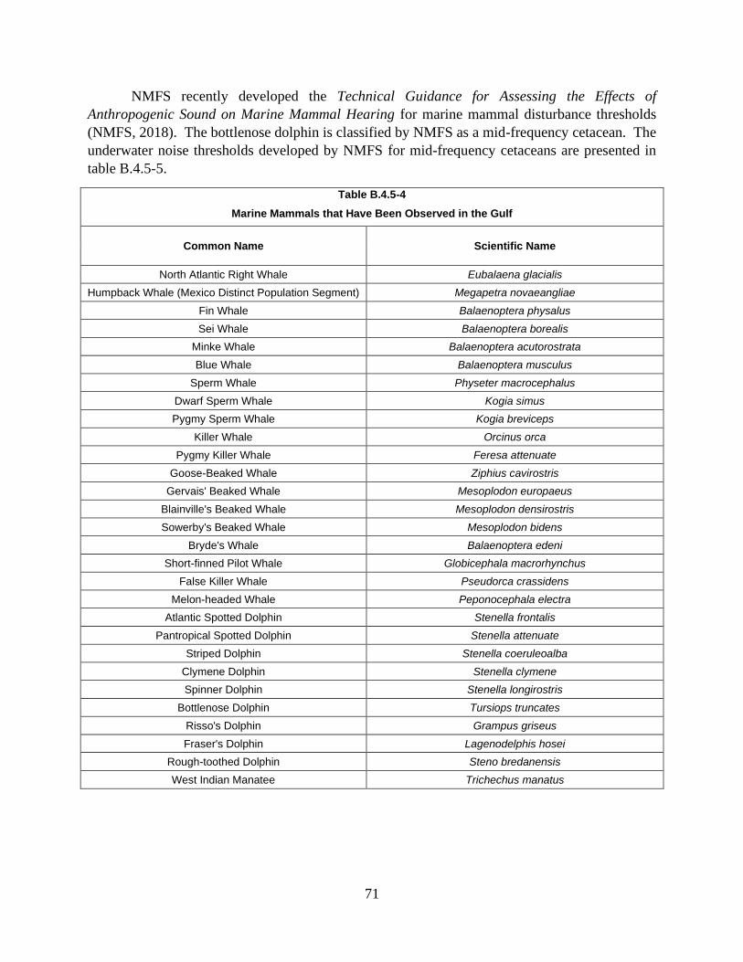
71
NMFS recently developed the Technical Guidance for Assessing the Effects of
Anthropogenic Sound on Marine Mammal Hearing for marine mammal disturbance thresholds
(NMFS, 2018). The bottlenose dolphin is classified by NMFS as a mid-frequency cetacean. The
underwater noise thresholds developed by NMFS for mid-frequency cetaceans are presented in
table B.4.5-5.
Table B.4.5-4
Marine Mammals that Have Been Observed in the Gulf
Common Name Scientific Name
North Atlantic Right Whale Eubalaena glacialis
Humpback Whale (Mexico Distinct Population Segment) Megapetra novaeangliae
Fin Whale Balaenoptera physalus
Sei Whale Balaenoptera borealis
Minke Whale Balaenoptera acutorostrata
Blue Whale Balaenoptera musculus
Sperm Whale Physeter macrocephalus
Dwarf Sperm Whale Kogia simus
Pygmy Sperm Whale Kogia breviceps
Killer Whale Orcinus orca
Pygmy Killer Whale Feresa attenuate
Goose-Beaked Whale Ziphius cavirostris
Gervais' Beaked Whale Mesoplodon europaeus
Blainville's Beaked Whale Mesoplodon densirostris
Sowerby's Beaked Whale Mesoplodon bidens
Bryde's Whale Balaenoptera edeni
Short-finned Pilot Whale Globicephala macrorhynchus
False Killer Whale Pseudorca crassidens
Melon-headed Whale Peponocephala electra
Atlantic Spotted Dolphin Stenella frontalis
Pantropical Spotted Dolphin Stenella attenuate
Striped Dolphin Stenella coeruleoalba
Clymene Dolphin Stenella clymene
Spinner Dolphin Stenella longirostris
Bottlenose Dolphin Tursiops truncates
Risso's Dolphin Grampus griseus
Fraser's Dolphin Lagenodelphis hosei
Rough-toothed Dolphin Steno bredanensis
West Indian Manatee Trichechus manatus

72
Table B.4.5-5
Underwater Sound Thresholds for Marine Mammals
Functional Hearing Group
Underwater Sound Thresholds b
Vibratory Pile Driving – Behavioral Disturbance a
Vibratory Pile Driving – Injury b,
c
Impact Pile Driving – Behavioral Disturbance a
Impact Pile Driving – Injury d, e
Marine Mammals (mid-frequency cetaceans)
Temporary Threshold Shift d
120 dB RMS 178 dB SELcum 224 dB Peak
160 dB RMS 170 dB SELcum
224 dB Peak
Marine Mammals (mid-frequency cetaceans)
Permanent Threshold Shift d 120 dB RMS
198 dB SELcum 230 dB Peak
160 dB RMS 185dB SELcum 230 dB Peak
a Source: NMFS, 2018. b The root mean square exposure level is the square root of the average sound pressures over the duration of
a pulse and represents the effective pressure and intensity produced by a sound source. c The cumulative sound exposure level is the energy accumulated over multiple strikes or continuous vibration
over a period of time. d Peak sound pressure level is the largest absolute value of instantaneous sound pressure. e The injury threshold is the general level for temporary or permanent threshold shift onset for mid-frequency
cetaceans as identified by NMFS (2016). Threshold shifts are influenced by the frequency of noise received and a cumulative sound exposure exceeding this level may not cause a threshold shift if outside the range of hearing.
SPLNG calculated the anticipated distances at which the thresholds presented in
table B.4.5-5 would be expected to occur. These distances are presented in table B.4.5-6 and
indicate that the thresholds would be exceeded at locations close to the pile driving activities,
even with the implementation of noise mitigation measures, such as bubble curtains or cushion
blocks.
Table B.4.5-6
Calculated Distances to Underwater Noise Thresholds for Marine Mammals from Dredging and Mitigated
In-water Pile Driving
Activity Distance from Source in which Threshold would be Exceeded
Permanent Injury Temporary Injury Behavioral Disturbance
Impact pile driving 80 feet 800 feet 1,522 feet
Vibratory pile driving 6 feet 127 feet 32,800 feet
Dredging < 0.1 feet 2 feet 9,606 feet
Based on the NMFS guidance (2016), thresholds for permanent and temporary injury to
marine mammals are anticipated to be exceeded within 80 feet and 800 feet of the in-water pile
driving activities, respectively. Behavioral thresholds would be exceeded for up to 6.2 miles
(i.e., 32,800 feet) from pile driving activities; therefore, an incidental take authorization from
NMFS may be required. During dredging activities, thresholds for permanent and temporary
injury to marine mammals are anticipated to be exceeded within 0.1 feet and 2 feet, respectively.
This indicates that injury from dredging noise is extremely unlikely. Behavioral thresholds for
dredging would be exceeded within 1.8 miles (i.e., 9,606 feet). Although bottlenose dolphins
would be expected to largely avoid the Project area during pile driving activities, the potential
exists for bottlenose dolphins to be injured during the first several strikes of the pile driving
hammer if they are in proximity to the pile-driving area.

73
SPLNG would reduce the potential for impacts on bottlenose dolphins during the first
several strikes of the pile driving hammer by using soft starts to the pile driving to ensure that
any dolphins have ample time to leave the injury radius before full pile driving commences. In
addition, we have included a recommendation in section B.4.2.2 to ensure that underwater noise
levels are not greater than predicted. However, the potential still exists for bottlenose dolphins
and other marine mammals to be injured during pile driving activities, and SPLNG has not
completed consultations with NMFS regarding pile driving activities. Therefore, we
recommend that:
• Prior to construction, SPLNG should file with the Secretary, for review and written
approval by the Director of OEP, mitigation measures to avoid or further minimize
take of marine mammals during in-water pile driving, developed in consultation
with NMFS.
Increased marine traffic could potentially affect marine mammals through vessel strikes
and spills of hazardous materials, as well as impacts related to the vessels’ usage of ballast and
cooling water. Impacts resulting from spills of hazardous materials and ballast and cooling water
exchanges would be similar to that discussed in section B.4.2.2 for fisheries resources.
Vessel traffic can result in strikes with marine species, which can cause mortality or
injury events, increased stress levels, or avoidance of the area by marine species. Due to their
preference for offshore waters and their relative rarity in Louisiana waters, the occurrence of
whales within the Project area would be limited to the portion of the LNGC transit route through
the Gulf of Mexico. In general, LNGCs move slowly and make more noise than other vessels,
allowing them to be more easily avoided by highly mobile wildlife. To minimize potential for
vessel strikes, LNGCs would adhere to the Vessel Strike Avoidance Measures and Reporting for
Mariners (2008). SPLNG would further minimize impacts on manatees through the
implementation of the FWS Standard Manatee Conditions for In-water Activities (2011) during
construction of the Project. Based on the implementation of the measures outlined above and our
recommendations, we conclude that the Project would not significantly impact marine mammals.
5.0 CULTURAL RESOURCES
Section 106 of the National Historic Preservation Act, as amended, requires FERC to
consider the effect of its undertakings on properties listed, or eligible for listing, on the National
Register of Historic Places, and to afford the Advisory Council on Historic Preservation an
opportunity to comment. SPLNG, as a non-federal party, is assisting us in meeting our
obligations under Section 106 of National Historic Preservation Act and implementing
regulations at 36 CFR 800.
5.1 Survey Results and Consultation
We sent copies of our NOI for the Project to a wide range of stakeholders, including the
Advisory Council on Historic Preservation, Louisiana Department Division of Archaeology,
Texas Historical Commission, and federally recognized Indian tribes (tribes) that may have an

74
interest in the Project area. The NOI stated that we use the NOI to initiate consultations with
State Historic Preservation Officers (SHPO)9 and to solicit their views and those of other
government agencies, interested tribes, and the public on the Projects’ potential effects on
historic properties.
The NOI was sent to 10 tribes, including the Coushatta Tribe of Louisiana, Caddo
Nation, Chitimacha Tribe, Alabama-Coushatta Tribe of Texas, Alabama-Quassarte Tribal Town,
the Choctaw Nation of Oklahoma, Jena Band of Choctaw Indians, Mississippi Band of Choctaw
Indians, and Tunica-Biloxi Indian Tribe. On May 31, 2018 in response to the NOI, the Choctaw
Nation of Oklahoma filed a letter with FERC stating that the Project is located within an area
that is of historic interest to the tribe and stated that they wish to exercise their right to enter into
government-to-government consultation with FERC. The Choctaw Nation of Oklahoma
requested additional information about the Project. SPLNG provided the requested information
on June 5, 2018. Following SPLNG’s filing of their Application with FERC, the Choctaw
Nation of Oklahoma filed an additional letter dated January 24, 2019 requesting the same
information that was previously provided by SPLNG.
In addition, SPLNG sent Project information to six tribes (Caddo Nation, Chitimacha
Tribe of Louisiana, Choctaw Nation of Oklahoma, Coushatta Tribe of Louisiana, Jena Band of
Choctaw Indians, and Tunica-Biloxi Indians of Louisiana). A summary of SPLNG’s
correspondence is provided in table B.5.1-1.
Table B.5.1-1
SPLNG’s Coordination with Federally Recognized Tribes
Native American Entity Date of Submittal Date of Response
Caddo Nation February 23, 2018
Original Project Introduction letter No response received
March 20, 2018
Follow-up phone call to initiate contact No response received
April 24, 2018
Revised Project Footprint Letter No response received
Chitimacha Tribe of Louisiana February 23, 2018
Original Project Introduction letter No response received
March 20, 2018
Follow-up phone call to initiate contact No response received
May 17, 2018
Sent Revised Project Footprint Letter No response received
Choctaw Nation of Oklahoma
NA
May 31, 2018
Additional information requested from FERC
9 In Louisiana and Texas, the SHPO is part of the Louisiana Division of Archaeology and Texas Historical
Commission, respectively.

75
Table B.5.1-1
SPLNG’s Coordination with Federally Recognized Tribes
Native American Entity Date of Submittal Date of Response
June 5, 2018 Requested information submitted No response received
Coushatta Tribe of Louisiana February 23, 2018
Original Project Introduction letter No response received
March 20, 2018
Follow-up phone call to initiate contact No response received
April 24, 2018
Revised Project Footprint Letter No response received
Jena Band of Choctaw Indians February 23, 2018
Original Project Introduction letter
April 4, 2018
No properties affected
March 20, 2018
Follow-up phone call to initiate contact No response received
April 24, 2018
Revised Project Footprint Letter No response received
Tunica-Biloxi Indians of Louisiana February 23, 2018-Original Project Introduction letter
No response received
March 20, 2018
Follow-up phone call to initiate contact No response received
April 24, 2018
Revised Project Footprint Letter No response received
SPLNG obtained concurrence from the Louisiana SHPO for previous Projects at the
SPLNG Terminal and surveys conducted adjacent to the SPLNG Terminal. Other concurrences
were requested and received for the use of additional areas within the previously surveyed
SPLNG Terminal. A summary of these investigations and concurrences, which include the areas
that would be affected by the Project, are summarized in table B.5.1-2.
Table B.5.1-2
Summary of SPLNG’s Cultural Resource Surveys and Consultations
Submittal Date of SHPO
Submittal Date of SHPO Concurrence
Corresponding FERC Docket
Number
Corresponding SPLNG Third Berth Expansion
Project Location
Request for Comments Regarding Dredge Material
Placement Plan April 5, 2004 April 29, 2004 CP04-47-000
Third Berth Area and other marine dredged
areas
Phase I Cultural Resources Survey for the Sabine Pass
Liquefied Natural Gas Terminal and Pipeline
Project, Cameron Parish, Louisiana
August 27, 2004 January 12,
2005 CP04-47-000
Existing access roads 1, 5, and 6, new permanent
access roads 7 and 8, Staging Areas 1, 2, 4,
and 6
Request for clearance for construction and operation
of the Phase II Project facilities
June 13, 2005 July 6, 2005 CP05-396-000 Portions of the Third
Berth Area adjacent to existing berth

76
Table B.5.1-2
Summary of SPLNG’s Cultural Resource Surveys and Consultations
Submittal Date of SHPO
Submittal Date of SHPO Concurrence
Corresponding FERC Docket
Number
Corresponding SPLNG Third Berth Expansion
Project Location
Request for clearance for construction and operation
of the Export facilities
September 29, 2008
November 18, 2008
CP04-47-001 & CP05-396-001
Discharge of ballast water for LNGCs
Request for clearance for construction and operation of the Liquefaction Project Facilities (Stage 1 and 2,
Liquefaction Trains 1 through 4)
June 17, 2010 July 2, 2010 CP11-72-000 A portion of staging area
3 and access roads 2 and 3
Phase 1 Cultural Resources Consult for the temporary
Workspace off of Light House Road
July 20, 2011 August 24,
2011 CP11-72-000 Staging area 5
Request for clearance for construction and operation
of the Liquefaction Expansion Project facilities
(Stage 3, Liquefaction Trains 5 and 6)
July 15, 2013 August 13,
2013 CP13-552-000
A portion of staging area 3, and access road 4
Request for clearance for road connection for the
Sabine Pass Liquefaction Project
November 18, 2013
November 21, 2013
CP11-72-000 CP13-2-000
A portion of access road 2
SPLNG Third Berth Expansion Project (LA)
February 23, 2018 March 27, 2018 PF18-3-000 Entire Third Berth Project
Area (all project components)
SPLNG Third Berth Expansion Project (TX)
April 2, 2018 April 30, 2018 PF18-3-000 Entire Third Berth Project
Area (all project components)
SPLNG Third Berth Expansion Project at the
Sabine Pass LNG Terminal – Outfall 001
July 26, 2018 August 27,
2018 PF18-3-000 Outfall 001
SPLNG Third Berth Expansion Project – New
Third Berth Area October 3, 2018
November 5, 2018
PF18-3-000 Revised Third Berth Area
Potential Wetland Mitigation Areas
November 14, 2018
January 9, 2019
CP19-11-000 Louisiana Point DMPA
SPLNG conducted cultural resources surveys and reviewed indirect effects on
aboveground resources within the project area of potential effect (APE). No traditional cultural
properties or properties of religious or cultural importance to Indian tribes have been identified in
the Project area. No archaeological or architectural sites have been identified in the direct APE.
The majority of the Project area was assessed in conjunction with the previously approved
projects at the SPLNG Terminal and the results have been reported to the SHPO for review.
SPLNG received concurrence from the Louisiana SHPO on March 27, 2018, agreeing that no
known historic properties would be affected. On July 26, 2018, SPLNG submitted an additional
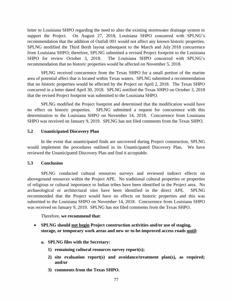
77
letter to Louisiana SHPO regarding the need to alter the existing stormwater drainage system to
support the Project. On August 27, 2018, Louisiana SHPO concurred with SPLNG’s
recommendation that the addition of Outfall 001 would not affect any known historic properties.
SPLNG modified the Third Berth layout subsequent to the March and July 2018 concurrence
from Louisiana SHPO; therefore, SPLNG submitted a revised Project footprint to the Louisiana
SHPO for review October 3, 2018. The Louisiana SHPO concurred with SPLNG’s
recommendation that no historic properties would be affected on November 5, 2018.
SPLNG received concurrence from the Texas SHPO for a small portion of the marine
area of potential affect that is located within Texas waters. SPLNG submitted a recommendation
that no historic properties would be affected by the Project on April 2, 2018. The Texas SHPO
concurred in a letter dated April 30, 2018. SPLNG notified the Texas SHPO on October 3, 2018
that the revised Project footprint was submitted to the Louisiana SHPO.
SPLNG modified the Project footprint and determined that the modification would have
no effect on historic properties. SPLNG submitted a request for concurrence with this
determination to the Louisiana SHPO on November 14, 2018. Concurrence from Louisiana
SHPO was received on January 9, 2019. SPLNG has not filed comments from the Texas SHPO.
5.2 Unanticipated Discovery Plan
In the event that unanticipated finds are uncovered during Project construction, SPLNG
would implement the procedures outlined in its Unanticipated Discovery Plan. We have
reviewed the Unanticipated Discovery Plan and find it acceptable.
5.3 Conclusion
SPLNG conducted cultural resources surveys and reviewed indirect effects on
aboveground resources within the Project APE. No traditional cultural properties or properties
of religious or cultural importance to Indian tribes have been identified in the Project area. No
archaeological or architectural sites have been identified in the direct APE. SPLNG
recommended that the Project would have no effects on historic properties and this was
submitted to the Louisiana SHPO on November 14, 2018. Concurrence from Louisiana SHPO
was received on January 9, 2019. SPLNG has not filed comments from the Texas SHPO.
Therefore, we recommend that:
• SPLNG should not begin Project construction activities and/or use of staging,
storage, or temporary work areas and new or to-be-improved access roads until:
a. SPLNG files with the Secretary:
1) remaining cultural resources survey report(s);
2) site evaluation report(s) and avoidance/treatment plan(s), as required;
and/or
3) comments from the Texas SHPO.
78
b. the Advisory Council on Historic Preservation is afforded an opportunity to
comment if historic properties would be adversely affected; and
c. the FERC staff reviews and the Director of OEP approves the cultural resources
reports and plans, and notifies SPLNG in writing that treatment
plans/mitigation measures (including archaeological data recovery) may be
implemented and/or construction may proceed.
All materials filed with the Commission containing location, character, and
ownership information about cultural resources must have the cover and any
relevant pages therein clearly labeled in bold lettering: “CUI//PRIV- DO NOT
RELEASE.”
6.0 LAND USE, RECREATION, AND VISUAL RESOURCES
6.1 Land Use
Land use classification was compiled from field surveys, USGS 7.5-quadrangle maps,
and high-quality aerial photographs. Land within the Project area is classified into the following
categories based on dominant land use and vegetative cover:
• Industrial/commercial: existing and approved facilities at the SPLNG Terminal and
existing paved roads;
• open water: unvegetated bodies of water including a perennial river and intermittent
stream; and
• wetland: mix of E2EM and E2SS.
Construction of the Third Berth would affect a total of about 375.2 acres of land, of
which 171.6 acres would be maintained for operation. All land within the SPLNG Terminal is
classified as either existing industrial/commercial land used for the existing and approved
facilities or open water and wetlands (Table 6.1-1). The southern portion of the Third Berth
would be located in an area that consists of dredged fill material comprised of very soft clays to
reach the current grade El +2 feet to +3 feet (NAVD 88). The northern portion of the proposed
Third Berth was previously improved with fill material consisting of fat clays and crushed
limestone to reach the current grade El +6 feet to +9 feet.
The majority of the SPLNG Terminal and overlapping Project areas are considered
industrial/commercial land use types. These areas are disturbed and are devoid of vegetation or
consist of impervious surfaces. Industrial land affected by construction and operation of the
Project would be limited to previously approved areas and existing permanent access roads. This
land is currently paved with impervious materials and the majority would remain as such during
and following construction; with the exception of impact areas for the proposed Third Berth;
which would be converted to open water.
The SPLNG Terminal is located on the eastern shore of Sabine Pass Channel, the
southern-most terminus of the Sabine-Neches Waterway. This waterway is a routinely

79
maintained/dredged ship channel with depths greater than -40 feet NAVD 88. Tidal exchange
between marine and estuarine systems occurs through the Sabine Pass Channel, which has been
extensively modified for navigational purposes. The Gulf Intracoastal Waterway enters the
Sabine-Port Arthur canal just south of Port Arthur, Texas, and exits via the Sabine River.
Bayous discharging into the Sabine-Neches canal and river system include Adams Bayou, Cow
Bayou, and Taylor Bayou. All of these bayous have been dredged along their lower reaches.
The open water land use category also includes an intermittent stream which provides
conveyance to stormwater discharges (Outfall 001).
Dredging for the proposed Third Berth would impact the Sabine Pass Channel and
adjacent E2EM and E2SS wetlands. Impacts would be permitted and mitigated under the terms
of the COE Section 404 Permit and Louisiana Coastal Use Permit. Impacts on shipping traffic
would be minimized through coordination with the Coast Guard. Section B.3.3 provides
additional information regarding the permanent conversion of wetlands to open water for the
proposed Third Berth.

80
Table B.6.1-1
Detailed Summary of Land Use Affected by Project Construction and Operation (acres)
Facility Indus./Comm. Open Water
e Wetland f Open Land Total
Construction
Third Berth 13.36 49.23 27.66 - 90.25
Outfall 001 0.20 0.01 - - 0.21
Staging Areas
Staging Area 1 35.27 - - - 35.27
Staging Area 2 15.48 - - - 15.48
Staging Area 3 113.13 - - - 113.13
Staging Area 4 15.79 - - - 15.79
Staging Area 5 a 80.16 - - - 80.16
Staging Area 6 12.65 - - - 12.55
Subtotal 272.48 - - - 272.48
Access Roads
Access Road 1 b 4.04 - - - 4.04
Access Road 2 b 1.04 - - - 1.04
Access Road 3 b 0.33 - - - 0.33
Access Roads 4 b 1.22 - - - 1.22
Access Road 5 b 0.91 - - - 0.91
Access Road 6 b 3.7 - - - 3.70
Access Road 7 c, d 0.80 - - - 0.80
Access Road 8 c 0.22 - - - 0.22
Subtotal 12.26 - - - 12.26
Construction Total 298.30 49.24 27.66 - 375.20
Operation
Third Berth 13.36 49.23 27.66 - 90.25
Outfall 001 0.12 0.01 - - 0.13
Staging Area 5 80.16 - - - 80.16
Access Road 7 c, d 0.80 - - - 0.80
Access Road 8 c 0.22 - - - 0.22
Operation Total 94.66 49.24 27.66 - 171.56
a Wetlands identified within Staging Area 5 would be avoided by Project construction. b Construction and operation acreages for existing access roads are based on a proposed 20-foot width. c Construction and operation acreages for new permanent access roads (Access Roads 7 and 8) are based
on a proposed 20-foot width. d A portion of Access Road 7 would be elevated on the trestle within the Third Berth. Acreages for this portion
of Access Road 7 have been accounted for as part of the acreages associated with the Third Berth. e Open water impacts include impacts to a perennial river and intermittent stream. f Wetland impacts include E2EM and E2SS.

81
6.2 Existing Residences and Planned Development
There are no residences within 50 feet of the SPLNG Terminal. The nearest residences
are 7,100 feet away, across the Sabine Pass Channel in Sabine Pass, Texas. SPLNG consulted
with Cameron Parish regarding planned residential or commercial developments that might be
affected by or occur within 0.25 mile of the SPLNG Terminal. No planned residential or
commercial developments were identified.
6.3 Recreation and Special Interest Areas
The proposed Project would not be located within 0.25 mile of landfills (LDEQ, 2018).
No national or state forests are within 0.25 mile of the proposed Project (USFS, 2018;
LDWF, 2018d, e, f). Likewise, the Project would not cross any state-owned lands (LDNR,
2018a). However, the State of Louisiana does own the water bottom within the Sabine Pass
Channel. SPLNG is working with the Louisiana State Land Office to amend its existing Water
Bottom Lease. SPLNG stated that it will file the 2nd Amendment to the Water Bottom Lease No.
566 once received from the Louisiana State Land Office.
Much of the coastal marsh in the immediate vicinity of the SPLNG Terminal is privately
owned and may be used for fishing, wildlife viewing, and other non-consumptive uses; as well as
for seasonal use for hunting. There are public boat ramps on both the Texas and Louisiana sides
of the SH 82 Sabine Pass Bridge. These are approximately 1.5 miles north of the LNG storage
tanks, as well as 0.5 mile south of the existing marine berth near the Sabine Pass Battleground
State Historic Park in Texas. These public boat ramps would not be affected by construction or
operation of the proposed Project at the SPLNG Terminal.
Currently, Natural Gas Pipeline of America, LLC (NGPL) and Port Arthur LNG/Port
Arthur Pipeline are also proposing to utilize Staging Area 2 and Duck Blind Road for proposed
projects (refer to section B.10.2 for additional information regarding these projects). SPLNG has
entered into a consent agreement with NGPL that would allow for surface lease with the
landowner and temporary use of specified areas within Staging Area 2.10 NGPL would use a
portion of Duck Blind Road during construction and NGPL would communicate and coordinate
with SPLNG on the delivery of equipment, material and other construction activities. Multiple
discussions were held with Port Arthur LNG and Port Arthur Pipeline during the first quarter of
2019. The Parties continue to work toward finalizing a binding agreement.
The Third Berth and turning basin would be constructed within and adjacent to a
federally maintained shipping channel. The SPLNG Terminal, including the loading berths, is a
secure site with restricted access. Recreational and commercial fishing activities are prohibited
within the secured footprint of the SPLNG Terminal facilities, of which the Third Berth and
turning basin would be included. The completed Third Berth would be a maintained industrial
shipping berth and would not provide optimum fisheries habitat. Construction of the Project
10 SPLNG currently leases the property from a private landowner.

82
would allow LNG vessel traffic to increase from 400 to 580 vessels per year which would
account for approximately a 0.25 percent increase in annual vessel traffic within the Sabine-
Neches Waterway (Sabine Neches Navigation District [SNND], 2018). However, this increase
in vessel traffic is not expected to significantly affect water quality or upstream/downstream
recreational fishing.
No State or National Parks are located within 0.25 mile of the proposed Project
(Louisiana Department of Culture, Recreation, and Tourism, 2018; NPS, 2018a). No nature
preserves protected by The Nature Conservancy (The Nature Conservancy, 2018) are located
within 0.25 mile of the proposed Project.
No registered natural landmarks are located within 0.25 mile of the proposed Project
(NPS, 2018b; NPS, 2018c) and no streams listed on the Nationwide Rivers Inventory would be
affected by the proposed Project (National Wild and Scenic Rivers System, 2018; NPS, 2018d).
The proposed Project would not affect or be within 0.25 mile of any trails designated
under the National Trails System or wilderness areas designated under the Wilderness Act
(NPS, 2018c; National Recreation Trails Program, 2013; University of Montana, 2018).
6.4 Contaminated or Hazardous Waste Sites
No hazardous waste sites or leaking underground storage tanks are located within 0.25
mile of the proposed Project (EPA, 2016; EPA, 2018b; LDEQ, 2018).
6.5 Coastal Zone Management
The Project is located within the Louisiana Coastal Zone and is subject to permitting
requirements pursuant to the Louisiana State and Local Coastal Resources Management Act and
in accordance with the federal Coastal Zone Management Act. The Louisiana Coastal Zone
boundary is established in Louisiana Revised Statutes Article 49, §214.24. The western and
eastern boundaries are the Louisiana borders with Texas and Mississippi, respectively. The
southern boundary is the state zone located approximately three miles offshore. The inland
boundary meanders from Texas to Mississippi and encompasses all of Cameron Parish. This
boundary is scientific-based, using a wide variety of parameters, including but not limited to,
tidal influence, sheet flow, soils, salinity, vegetation, fish and wildlife, topography, geology,
geography, economy and recreation (LDNR, 2018b).
The Coastal Zone Management Program is administered by the Office of Coastal
Management of the LDNR. The Project would be entirely located within the Louisiana Coastal
Zone boundary with the exception of existing Project areas located above the five-foot above
mean sea level contour. The LDNR, Office of Coastal Management is responsible for
permitting associated with activities occurring within the Louisiana Coastal Zone. The Project
application for Coastal Zone was placed on Public Notice on May 15, 2019, by the LDNR
Office of Coastal Management. To date, only one comment was received by the Louisiana
Department of Wildlife and Fisheries on May 22, 2019. On June 4, 2019, LDNR Office of
Coastal Management issued a letter requesting additional information on the mitigation

83
alternatives analysis. On June 12, 2019, SPLNG provided responses to the LDNR Office of
Coastal Management. SPLNG continues to consult with LDNR Office of Coastal Management
to obtain Coastal Use Permit. Therefore, SPLNG submitted a Joint Permit Application for a
Coastal Use Permit to the Office of Coastal Management in October 2018. The Commission
may not authorize construction until the Coastal Zone Management Act consistency
determination is rendered. Therefore, we recommend that:
• Prior to construction, SPLNG should file with the Secretary a copy of the
LDNR’s Coastal Zone Management Act consistency determination for the
Project.
6.6 Visual Resources
The existing SPLNG Terminal is located in an undeveloped part of Cameron Parish
where the nearest residences and schools with potential views of the SPLNG Terminal are
located over one mile away. Potential public viewpoints include public boat ramps on both sides
of the SH 82 bridge north of the SPLNG Terminal site, the community of Sabine Pass, the
Sabine Pass Battleground State Historical Park, the J.D. Murphree Wildlife Management Area,
and the Texas Point National Wildlife Refuge on the west side of Sabine Pass Channel. The
primary Project components that would have a visual impact on surrounding areas are the
proposed Third Berth LNG loading facilities. These new facilities would be installed adjacent to
the existing marine berth and would be similar in size and appearance.
The Project includes new facilities and structures that would require proper lighting for
operations and safety purposes. Each light would consist of instant re-strike high-pressure
sodium lights with down-shields installed to reduce upward illumination, light spill, and glare to
minimize visual disturbances of the surrounding wildlife and environment (including ships
navigating the Sabine Pass River Channel). During construction, light plants would provide
lighting during early hours and late hours of the work shifts, particularly during winter months.
SPLNG consulted with FWS and they indicated that the shoreline at the Third Berth
would not provide suitable habitat for nesting birds and therefore potential impacts on migratory
birds would be minimal.
Lighting for the Third Berth would be similar to approved lighting currently in place for
the existing SPLNG Terminal marine berth and other marine facilities in the area. Since the
Third Berth would provide minimal fisheries habitat, SPLNG does not anticipate that lighting
required for construction and operation of the Third Berth would significantly affect marine
resources in the area.
Construction and operation of the Project facilities would be visible or partially visible to
motorists using SH 82 which is part of the Creole Natural Trail All-American Road, a 180-mile
collection of highways near Lake Charles, Louisiana designated as a national scenic byway
(Federal Highway Administration, 2018). Construction and operation of the Project facilities
would also be visible or partially visible to boaters in the Sabine Pass Channel, and residents or
visitors in Sabine Pass, Texas and surrounding areas. Although the terrain is generally flat and

84
vegetation relatively low-profile, views of the SPLNG Terminal are intermittent to motorists on
SH 82, users of the boat ramps, and the community of Sabine Pass due to the configuration of the
roadways, existing vegetation, and other industrial development along the Texas shoreline of the
Sabine Pass Channel. Further, visual impact on the surrounding area during construction and
operation of the Project would be minimal since the new facilities would be viewed in
conjunction with the existing LNG tanks, marine berth, and facilities already in operation at the
SPLNG Terminal site. These existing facilities are now part of the visual environment such that
the addition of the Third Berth would have no appreciable effect on the aesthetics of the area.
7.0 SOCIOECONOMICS
Socioeconomics is an evaluation of the basic conditions (attributes and resources)
associated with the human environment, particularly the population and economic activity within
a region. Economic activity generally encompasses regional employment, personal income, and
revenues and expenditures. Impacts on the fundamental socioeconomic components can
influence other issues such as regional housing availability and provision of community services.
All data presented in this section represents the most current data available at the writing of this
EA.
This section addresses several different factors that could affect the quality of life and
economy in the area surrounding the Project where employees might live, shop, and use public
resources. These factors include public services such as fire, police, and medical facilities;
educational facilities; and environmental justice.
The socioeconomic analysis for the proposed Project examines data from Cameron Parish
and Jefferson County, as well as Port Arthur, Texas, where the majority of the Project workforce
is anticipated to reside during construction and operation.
7.1 Population, Economy, and Employment
Table B.7.1-1 provides a summary of current and projected populations of the affected
counties and Port Arthur, Texas.
Table B.7.1-1
Existing population and Demographic Conditions
Demographic Louisiana Cameron
Parish, LA Texas
Jefferson County, TX
Port Arthur, TX
2018 Population Estimate 4,659,978 6,968 28,701,845 255,001 55,498 (2017)
2018 Population Density (persons per square mile)
104.9 5.3 96.3 287.9 699.8
Population Change Since 2010 (percent)
2.8 1.5 14.1 1.1 UA
Projected Population Change from 2020 to 2030
(percent) 4.9 -7.2 13.4 1.0 -1.6
Source: U.S. Census Bureau, 2018; World Population Review, 2019; Blanchard, 2007; Potter and Hoque, 2014; Texas Demographic Center, 2019; Van Zandt, 2012.

85
Table B.7.1-1
Existing population and Demographic Conditions
Demographic Louisiana Cameron
Parish, LA Texas
Jefferson County, TX
Port Arthur, TX
UA = Data unavailable
While populations rose in both Cameron Parish and Jefferson County, the increase
between 2010 and 2018 were at slower rates than the States of Louisiana and Texas,
respectively. Populations in both states are expected to continue to increase, while populations
in Jefferson County and Cameron Parish are expected to either remain relatively stable or
decrease over the next decade (Blanchard, 2007; Potter and Hoque, 2014; Texas Demographic
Center, 2019). The city of Port Arthur, Texas, which is the closest large municipality to the
Project, had a population of 55,498 in 2017 (World Population Review, 2019). Similar to the
population trends exhibited by Jefferson County, the population of Port Arthur, Texas is
expected to remain stagnant over the next decade (Van Zandt, 2012).
Table B.7.1-2 presents income and employment conditions for Cameron Parish,
Louisiana and Jefferson County, Texas, as well as the major municipalities closest to the Project.
Table B.7.1-2 Existing Income and Employment Conditions in the Project Area
Income Characteristic Louisiana Cameron
Parish, LA Texas
Jefferson County, TX
Port Arthur, TX
2017 Estimate: Per Capita Income (dollars)
26,205 29,681 28,985 25,370 18,417
2017 Estimate: Population Below
Poverty Level (percent) 19.6 8.7 16.0 19.4 30.7
2017 Estimate: Civilian Labor Force
2,188,424 3,215 13,473,957 112,595 21,209
2017 Estimate: Unemployment Rate
(percent) 7.2 3.0 5.8 6.5 9.2
Major Industry EH&SS a EH&SS a EH&SS a EH&SS a Construction
Manufacturers’ Shipments, 2012 ($1000)
271,191,050 0 702,603,073 80,760,488 D b
Wholesale Trade Sales, 2012 ($1000)
86,300,969 29,928 1,129,150,714 2,450,990 D b
Retail Sales, 2012 ($1000)
61,396,364 28,323 356,116,376 3,968,309 865,822
Accommodation and Food Service Sales,
2012 ($1000) 11,697,949 1,364 54,480,811 485,461 86,422
Source: U.S. Census Bureau, 2018. a EH&SS = Education, health care, and social services b Suppressed to avoid disclosure of confidential information
Education, healthcare, and social services were the biggest industry in both Cameron
Parish and Jefferson County, while construction was the biggest industry in Port Arthur, Texas.
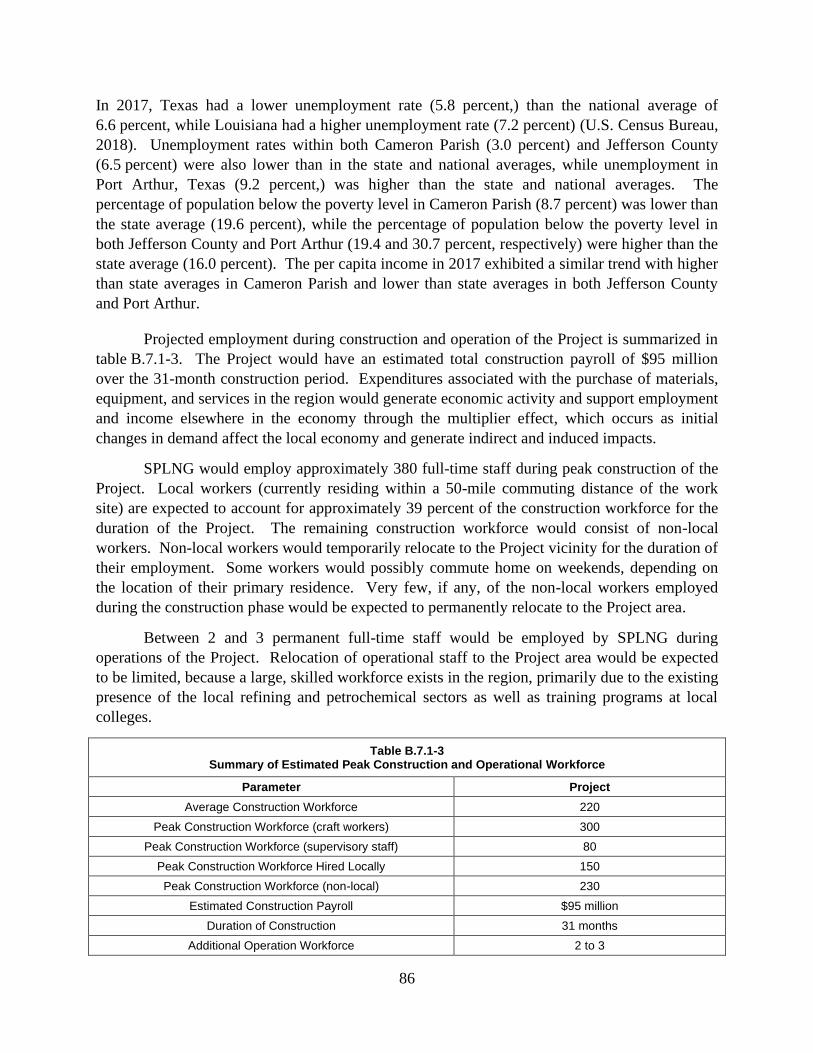
86
In 2017, Texas had a lower unemployment rate (5.8 percent,) than the national average of
6.6 percent, while Louisiana had a higher unemployment rate (7.2 percent) (U.S. Census Bureau,
2018). Unemployment rates within both Cameron Parish (3.0 percent) and Jefferson County
(6.5 percent) were also lower than in the state and national averages, while unemployment in
Port Arthur, Texas (9.2 percent,) was higher than the state and national averages. The
percentage of population below the poverty level in Cameron Parish (8.7 percent) was lower than
the state average (19.6 percent), while the percentage of population below the poverty level in
both Jefferson County and Port Arthur (19.4 and 30.7 percent, respectively) were higher than the
state average (16.0 percent). The per capita income in 2017 exhibited a similar trend with higher
than state averages in Cameron Parish and lower than state averages in both Jefferson County
and Port Arthur.
Projected employment during construction and operation of the Project is summarized in
table B.7.1-3. The Project would have an estimated total construction payroll of $95 million
over the 31-month construction period. Expenditures associated with the purchase of materials,
equipment, and services in the region would generate economic activity and support employment
and income elsewhere in the economy through the multiplier effect, which occurs as initial
changes in demand affect the local economy and generate indirect and induced impacts.
SPLNG would employ approximately 380 full-time staff during peak construction of the
Project. Local workers (currently residing within a 50-mile commuting distance of the work
site) are expected to account for approximately 39 percent of the construction workforce for the
duration of the Project. The remaining construction workforce would consist of non-local
workers. Non-local workers would temporarily relocate to the Project vicinity for the duration of
their employment. Some workers would possibly commute home on weekends, depending on
the location of their primary residence. Very few, if any, of the non-local workers employed
during the construction phase would be expected to permanently relocate to the Project area.
Between 2 and 3 permanent full-time staff would be employed by SPLNG during
operations of the Project. Relocation of operational staff to the Project area would be expected
to be limited, because a large, skilled workforce exists in the region, primarily due to the existing
presence of the local refining and petrochemical sectors as well as training programs at local
colleges.
Table B.7.1-3 Summary of Estimated Peak Construction and Operational Workforce
Parameter Project
Average Construction Workforce 220
Peak Construction Workforce (craft workers) 300
Peak Construction Workforce (supervisory staff) 80
Peak Construction Workforce Hired Locally 150
Peak Construction Workforce (non-local) 230
Estimated Construction Payroll $95 million
Duration of Construction 31 months
Additional Operation Workforce 2 to 3

87
7.2 Housing
Part of the construction workforce would be hired and/or contracted locally, and they
would likely commute to and from their homes to work each day. The remaining construction
workforce is assumed to permanently reside further than commuting distance from the Project
sites and would be expected to temporarily relocate to the Project vicinity for the duration of
their employment; possibly commuting home on weekends, depending on the location of their
primary residence.
Housing resources are summarized by county and nearby communities in table B.7.2-1.
These estimates suggest that rental housing would be available in Cameron Parish and Jefferson
County, with a substantial number of units available for rent in Port Arthur, Texas, which
would be located within commuting distance of the proposed Project. Additional units
classified for seasonal, recreational, or occasional use may also be available (table B.7.2-1).
Table B.7.2-1 Temporary Housing Units Available in the Project Vicinity
Demographic Louisiana Cameron
Parish, LA Texas
Jefferson County, TX
Port Arthur, TX
2017 Estimate: Number of
Vacant Housing Units
293,419 1,123 1,180,967 13,696 4,115
2017 Estimate: Rental Vacancy Rate (percent)
8.3 14.5 7.6 7.3 7.9
2010 Estimate: Number of
Vacant Housing Units for
Seasonal, Recreational, or Occasional Use
42,253 779 208,733 973 299
2017 Estimate: Number of
Renter Occupied Housing Units
600,183 272 3,579,373 35,839 8,918
2018 Number of Hotels/Motels
1,875 7 8,625 96 29
2018 Number of Campgrounds and RV Parks
342 17 619 47 30
Sources: U.S. Census Bureau, 2018; HotelMotels.info, 2018; Cameron Parish Tourist Commission, 2018; Yellow Pages, 2018; Roverpass, 2018
The vacant rental housing, motels/hotels, and RV parks in the Project vicinity would be
sufficient to accommodate the estimated peak non-local workforce during construction. Since
many workers are expected to room with each other to lower costs, and peak construction
months would be limited, the available housing is expected to be considerably more than needed.
Due to the number of non-local workers and the high availability of temporary housing, we

88
conclude that construction of the Project would have a minor, temporary impact on housing in
the affected area.
Operation of the Project would result in a limited number of non-local workers
permanently relocating to the affected area. However, even if all operation personnel were non-
local, an adequate number of housing units would be available. Therefore, we conclude that
operation of the Project would have a negligible, but permanent impact on the local housing
market.
7.2.1 Displacement of Residences and Businesses
The Project facilities would be primarily located within or immediately adjacent to
industrial land associated with the existing SPLNG Terminal, and there are no existing or
planned residential developments within 0.25 of the Project. Therefore, we conclude that
construction and operation of the Project would be not displace residences or businesses.
7.3 Public Services
This section describes the community and public services available within the affected
area, including schools, emergency response and medical facilities, and fire and police
departments. Construction of the Project could result in increased demand for public services.
Table B.7.3-1 provides a summary of local community services in the Project area.
Table B.7.3-1 Public Service Data for the Project Vicinity
Parish/County/City, State
Number of Public Schools
Number of Police
Departments
Number of Fire Departments (by type)
Number of Hospitals a
Number of Hospital Beds
Cameron Parish, LA 4 1 3 (Volunteer) 1 49
Jefferson County, TX 74 7 6 (Career) / 4 (Volunteer) 4 1,001
Port Arthur, TX 17 1 1 (Career) 2 456
Totals 95 9 7 (Career) / 7 (Volunteer) 7 1,506
Sources: Public School Review, 2018; USACops, 2018; Fire Department Directory, 2018; Louisiana Hospital Inform, 2018; American Hospital Directory: Texas, 2018
a Hospitals do not include rehabilitation, long-term, and psychiatric hospitals.
Health care demands during the Project construction phase would include emergency
medical services to treat injuries resulting from construction accidents such as slips, trips, and
falls. Medical facilities within the Project vicinity would be sufficient to absorb any increase in
demand by the temporary construction workforce, with minimal cost to the local governments.
The addition of 380 full-time workers during construction of the Project would have a negligible
effect on hospitals.
Construction-related demands on local agencies could include increased enforcement
activities associated with issuing permits for vehicle load and width limits, local police assistance
during construction at road crossings to facilitate traffic flow, and emergency medical services to
treat injuries resulting from construction accidents. We conclude that construction of the Project
would have only minor and temporary negative impacts on the local police and fire services.

89
The Project would be located within the Cameron Parish School District; however, it is
anticipated that a majority of construction workers with families would reside in Port Arthur,
Texas, which is located within the Port Arthur Independent School District. Table B.7.3-2 lists
the number of public schools and provides detailed information on the school districts and school
enrollment that would be within the Project vicinity. During the 2018-2019 school year, there
were 10,088 students enrolled in 20 schools located within the two school districts (Public
School Review, 2018).
Table B.7.3-2 School Districts and School Enrollment in the Project Vicinity
Parish/County/School District
Total in District Sub-Total by Grade
Number of Schools
School Enrollment
Grades Number of
Schools School
Enrollment
Cameron Parish, Louisiana
Cameron Parish School District 3 600 PK-12 3 600
Jefferson County, Texas
Port Arthur Independent School District
17 9,488
PK 1 429
PK-2 1 386
PK-5 6 4,114
3-5 1 359
6-8 2 1,581
6-12 2 516
9 1 608
9-12 1 NA
10-11 1 3
10-12 1 1,492
Totals 20 10,088 20 10,088
Source: Public School Review, 2018.
PK = Pre-Kindergarten
A small portion of non-local workers temporarily relocating to the Project area could be
accompanied by their families. The potential addition of a limited number of students in the
Project vicinity would not be expected to affect existing average student/teacher ratios in any one
location. The addition of about 380 full-time workers during construction and 2 to 3 workers
during operation of the Project would have a negligible effect on the local school systems,
because the local workers would be hired from the local/regional labor pool and a small number
of non-local workers would relocate with families.
7.4 Transportation and Traffic
7.4.1 Land Transportation and Traffic
Construction traffic would access the Project site primarily from the Port Arthur, Texas
area via SH 82. Once at the site, construction traffic would utilize the SPLNG Terminal main
entrance road (Lighthouse Road or access road 6), which parallels the eastern boundary of the

90
property. Material deliveries to the site would be via truck using the same access point as
construction traffic. Heavy material delivers to the site would be via barge to the on-site
construction dock, or via SH 27 to SH 82 from Holly Beach, Louisiana.
There would be an increase in heavy truck traffic and workforce traffic to the Project site
during construction. SPLNG estimates an average of 8 to 12 deliveries via truck per day during
construction, with a peak of 18 to 23 trips per day. A similar number of small, two-axle truck
deliveries would also be expected during construction. Heavy material delivery would be via
barge to the on-site construction dock, or via SH 27 to SH 82 from Holly Beach, Louisiana. It is
anticipated that the material delivery vehicles would not exceed the load capacity of either the
public roads or the SH 82 bridge. Workers would access the Project site via a combination of
personal vehicles and busses. SPLNG estimates an average of 20 to 30 personal vehicles and
four to eight busses would be used to access the site per day, with a peak of 60 to 80 personal
vehicles and 10 to 12 busses per day.
Based on available traffic count data, construction of the Project is not expected to
significantly impact traffic flow on SH 82, as the estimated peak volume of vehicles entering the
facility off of SH 82 represents a daily increase of approximately 7 percent. This is based on the
existing annual average daily traffic of 1,897 vehicles per day traveling the stretch of SH 82 near
the existing SPLNG Terminal (Louisiana Department of Transportation and
Development, 2018). The increase in traffic would be temporary and represents a relatively
small increase in existing traffic on the surrounding roadways.
Operation of the facility would require an increase of 2 to 3 permanent employees.
Assuming these workers would each commute to work in their own vehicles, the addition of
these vehicle trips per day would be equivalent to 0.1 percent of existing traffic volumes as
measured on SH 82 near the existing SPLNG Terminal. Therefore, the increase in traffic
associated with the operation of the Project would be minor and not significant.
7.4.2 Marine Transportation and Traffic
Barges would be utilized during construction to transport equipment and materials to the
existing construction dock located on-site, thus reducing the impact of material deliveries on the
area road networks. Barges would access the Project site via the Gulf Intracoastal Waterway and
the Sabine Pass and Port Arthur Ship Channels. SPLNG anticipates that the number and type of
barge deliveries that occur during construction would be as follows: four barges for sheet pile
material, two barges for trestle and mooring and breasting dolphins, 56 barges for stone and rip
rap, five barges for precast girders and planks, and three barges for construction cranes.
Assuming that barges are transported in pairs, approximately 35 voyages would be required to
deliver the listed materials for construction. The number of deliveries to the Project site that
would occur via barges is not expected to affect existing marine transportation patterns.
Operation of the Project would result in an anticipated increase in the maximum marine
vessel traffic from the currently-authorized 400 LNGCs per year up to 580 LNGCs per year. No
additional security vessels would be added to support the additional ship calls for the Project. In
lieu of a Project-specific transportation plan for marine traffic, SPLNG developed a preliminary

91
WSA, which addresses overall traffic patterns, waterway conditions, and safety and security
matters for the proposed LNGC traffic in conjunction with other existing and potential future
marine traffic. SPLNG submitted the WSA to the Coast Guard in January 2018 as part of a
request for a LOR confirming that the increase of up to 180 LNGCs per year would not
significantly impact the waterway. In a letter dated May 21, 2019, the Coast Guard issued the
LOR for the Project, which stated that the Sabine Pass Channel is considered suitable for the
increased LNGC traffic associated with the Project in accordance with the guidance in the Coast
Guard Navigation and Vessel Inspection Circular 01-2011.
For the additional 180 LNGCs, SPLNG would follow the current procedures and
regulations that are applicable to escort a LNGC calling at the existing Berths 1 and 2. For
inbound/outbound transit of each LNGC, the Coast Guard has delegated authority to the local
Sheriff’s department to complete any security escort activity. The Sheriff’s department would
provide the escort for the last 30 minutes of each LNGC transit inbound and the first 20 minutes
of each LNGC transit outbound. The security vessel would not escort the LNGC for the entire
duration of the transit inbound or outbound. Historical site experience has shown that these very
limited duration “security vessel escorts” for LNGC inbound/outbound transit activity would
occur about 80 percent of the time.
7.5 Property Values
Although property values could be affected by the construction and operation of the
Project, the exact impact on a regional level is unknown. Ultimately, a potential purchaser
would make an offer to purchase based on his or her own values, which may or may not take the
LNG terminal into account. Since the Project would result in the modification of an existing
facility, property values are not anticipated to be affected by the Project.
7.6 Tax Revenues
SPLNG estimates that the Project would bring an influx of jobs and tax money to the
Project area. Both the materials purchased during construction as well as the goods and services
purchased by construction staff would be subject to sales tax. Therefore, SPLNG anticipates that
the tax revenue generated during construction of the Project would be $13 million.
During operations, SPLNG anticipates that the purchase of equipment or materials would
be expected to generate approximately $15 million in sales tax. The estimated average annual
property taxes attributable to the operation of the Project for the subsequent twenty years
(i.e., year 11 through year 31) would be approximately $2 million per year.
7.7 Environmental Justice
For projects with major aboveground facilities, FERC regulations (18 CFR 380.12(g)(1))
direct us to consider the impacts on human health or the environment of the local populations,
including impacts that would be disproportionately high and adverse for minority and low-
income populations.

92
The EPA’s Environmental Justice Policies (which are directed, in part, by Executive
Order 12898: Federal Action to Address Environmental Justice in Minority Populations and
Low-Income Populations) focus on enhancing opportunities for residents to participate in
decision making. The EPA (2019b) states that Environmental Justice involves meaningful
involvement so that: “(1) potentially affected community residents have an appropriate
opportunity to participate in decisions about a proposed activity that would affect their
environment and/or health; (2) the public’s contributions can influence the regulatory agency’s
decision; (3) the concerns of all participants involved would be considered in the decision-
making process; and (4) the decision-makers seek out and facilitate the involvement of those
potentially affected.”
In accordance with the Executive Order 12898, all public documents and notices for the
Project were made readily available to the public during our review of the Project. SPLNG
notified the various landowners and stakeholders located in the vicinity of the Project and held
an open house on April 17, 2018 to provide information to interested parties. As discussed in
section A.5.0, FERC staff also conducted outreach efforts such as mailing the NOI to about
120 parties notifying them of the Project.
The Council on Environmental Quality (CEQ) also has called on federal agencies to
actively scrutinize a number of important issues with respect to environmental justice
(CEQ, 1997). As part of our NEPA review, we have evaluated potential environmental justice
impacts related to the Project taking into account the following:
• the racial and economic composition of affected communities;
• health-related issues that may amplify project effects on minority or low-income
individuals; and
• public participation strategies, including community or tribal participation in the
NEPA process (CEQ, 1997).
The EPA provides guidance on determining whether there is a minority or low-income
community to be addressed in a NEPA analysis. According to this guidance, minority
population issues must be addressed when they comprise over 50 percent of an affected area or
when the minority population percentage of the affected area is substantially greater than the
minority percentage in the larger area of the general population. According to USC 689(3), low-
income populations are defined as a geographic area represented by a census tract or equivalent
county division where the poverty rate is 20 percent or greater. Therefore, low-income
populations for this analysis were determined to be those with 20 percent or greater of the
population living below the poverty threshold or when the percent of the population in the
affected area living below the poverty threshold is substantially greater than the percent of the
population living below the poverty threshold in the larger area of the general population (e.g.,
county or parish).
In accordance with these guidelines, we prepared an environmental justice analysis for
the Project utilizing a three-step approach to conduct our review. These steps are:

93
• determine the existence of minority and low-income populations;
• determine if resource impacts are high and adverse; and
• determine if the impacts fall disproportionately on environmental justice populations.
To develop a more accurate understanding of the racial and ethnic characteristics of the
communities in the immediate vicinity of the Project facilities, data were used from census block
groups, as opposed to the larger geographic areas included in census tract and county level data.
The EPA’s Environmental Justice Screening and Mapping Tool was utilized, in part, to confirm
the presence of census block groups that contain minority and low-income populations
(EPA, 2018c). In this analysis, the minority and low-income population percentages in the
States of Texas and Louisiana and the Project-area counties were compared to the respective
percentages within the census block groups intersected by a 2.0-mile radius around the Project.
These census block groups comprised the affected community based on the potential
environmental impact.
Table B.7.7-1 and figure B.7.7-1 provide an overview of the racial composition and
economic characteristics of the population in the block groups within a 2-mile radius of the
Project.
Table B.7.7-1 Minority Populations and Low-Income Population Information for the Census Block Groups Within 2 Miles of
the Project
State / County / Census Tract Block Group
Total Population
White (%)
Hispanic or Latino
origin (of any race)
(%)
African American
(%)
Asian (%)
Some Other Race (%) a
Total Minority
Population (%)
Percent Below
Poverty Level
State of Louisiana
4,531,570 59.0 5.0 32.0 1.7 2.3 41.0 19.6
Cameron Parish 6,797 91.3 5.5 2.8 0.3 0.1 8.7 8.7
Census Tract 9702.01, Block
Group 2 119 94.1 0.0 0.0 1.7 4.2 5.9 10.1
State of Texas 27,419,612 42.8 38.9 11.7 4.5 2.1 57.2 16.0
Jefferson County
238,304 41.8 19.5 33.7 3.6 1.4 58.2 19.4
Census Tract 116, Block Group 1
1,076 87.2 7.7 5.0 0.0 0.1 12.8 10.0
Sources: U.S. Census Bureau, 2017 a The Other Race category is inclusive of census respondents identifying as American Indian and Alaska Native; Native Hawaiian and Other Pacific Islander; and/or Some Other Race. Bold values indicate a percentage that exceeds thresholds defined in text, and is an environmental justice population.

94
Figure B.7.7-1 Third Berth Expansion Project General Location Map

95
Neither of the two census block groups located within 2.0 miles of the Project have
minority populations greater than the general EPA guidance of 50 percent or poverty rates that
exceed 20 percent. Similarly, neither of the two census block groups were determined to have
minority populations or poverty rates that were significantly greater than the reference
communities. Construction and operation of the Project would have positive socioeconomic
impacts on the local communities by stimulating economic growth and employment and by
increasing the local tax base (see sections B.7.1 and B.7.6). Therefore, we have determined that
construction and operation of the Project would not have a disproportionate adverse impact on
environmental justice communities.
8.0 AIR QUALITY AND NOISE
8.1 Air Quality
Air quality would be affected by construction and operation of the Project. This section
addresses the construction- and operation-based emissions from the Project as well as applicable
regulatory requirements and projected impacts on air quality. The term air quality refers to the
relative concentrations of pollutants in the ambient air. The subsections below describe well-
established air quality concepts that are applied to characterize air quality and to determine the
significance of increases in air pollution. This includes metrics for specific air pollutants known
as criteria pollutants, in terms of ambient air quality standards, regional designations to manage
air quality known as Air Quality Control Regions (AQCR), and the ongoing monitoring of
ambient air pollutant concentrations under state and federal programs.
Combustion of fossil fuels, such as natural gas, produces criteria air pollutants, such as
nitrogen dioxide (NO2), carbon monoxide (CO), sulfur dioxide (SO2), and inhalable particulate
matter (PM2.5 and PM10). PM2.5 includes particles with an aerodynamic diameter less than or
equal to 2.5 micrometers, and PM10 includes particles with an aerodynamic diameter less than or
equal to 10 micrometers. Combustion of fossil fuels also produces volatile organic compounds
(VOCs), a large group of organic chemicals that have a high vapor pressure at room temperature;
and oxides of nitrogen (NOx). VOCs react with nitrogen oxides, typically on warm summer
days, to form ozone, which is another criteria air pollutant. Other byproducts of combustion are
greenhouse gases (GHGs) and hazardous air pollutants (HAPs). HAPs are chemicals known to
cause cancer and other serious health impacts.
Other pollutants, not produced by combustion, are fugitive dust and fugitive emissions.
Fugitive dust is a mix of PM2.5, PM10, and larger particles thrown up in to the atmosphere by
moving vehicles, construction equipment, earth movement, and/or wind erosion. Fugitive
emissions, in the context of this EA, would be fugitive emissions of methane and/or VOCs from
operational pipelines and aboveground facilities.
8.1.1 Regional Climate
The Project site is located on the flat Coastal Plain in the extreme southwestern corner of
Louisiana. Based on information and data for Port Arthur, Texas, the climate is a mixture of
tropical and temperate zone conditions. In general, the Sabine Pass area has very short, mild

96
winters and long, hot and humid summers, although sea breezes (from the Gulf of Mexico)
prevent the occurrence of extremely high temperatures. Climate data obtained from NOAA for
the period 1981 through 2010 show an annual average temperature of 69 °F. Daily average high
temperatures range from 62 °F during January to 92 °F during August. Daily average low
temperatures range from 43 °F in January to 74 °F during July and August. The record
minimum and maximum temperatures are 12 °F and 108 °F, respectively. High humidity is the
result of fairly evenly distributed rainfall and proximity to the Gulf of Mexico, resulting in an
annual average relative humidity of 79 percent.
Precipitation is fairly evenly distributed throughout the year, with the lowest amounts
falling during early-spring and the highest amounts falling during the summer. The annual
average precipitation amounts to approximately 60 inches, with a monthly maximum of
7.1 inches in June and a monthly minimum of 3.2 inches in April. Much of the precipitation
during the summer occurs in short duration thunderstorms. Tropical storms or hurricanes,
although infrequent, can also enhance the summer and autumn rainfall in this region.
The predominant wind direction for most of the year is southerly, with a shift to north-
northeasterly during the fall and winter. The annual average wind speed is approximately
8.5 miles per hour (mph), with the highest average monthly wind speeds occurring during late-
winter/spring. The prevailing southerly wind is further enhanced during spring and summer by
thermal winds which develop when the air over the heated land further inland from the coast is
warmer than the air over the relatively cooler waters of the Gulf of Mexico.
Existing Air Quality
The EPA has established National Ambient Air Quality Standards (NAAQS) for six
criteria pollutants: SO2, CO, ozone (O3), NO2, particulate matter (PM10 and PM2.5), and lead.
There are two classifications of NAAQS, primary and secondary standards. Primary standards
set limits the EPA believes are necessary to protect human health including sensitive populations
such as children, the elderly, and asthmatics. Secondary standards are set to protect public
welfare from detriments such as reduced visibility and damage to crops, vegetation, animals, and
buildings.
Individual state air quality standards cannot be less stringent than the NAAQS. The
federal NAAQS for criteria pollutants are the same as the state standards established by the
LDEQ as outlined in the Louisiana Administrative Code (LAC) 33:III.711.A and 711.B. The
federal/state ambient air quality standards are summarized in table B.8.1-1.
Air Quality Control Regions and Attainment Status
AQCRs are areas established for air quality planning purposes in which state
implementation plans (SIPs) describe how ambient air quality standards would be achieved and
maintained. AQCRs were established by the EPA and local agencies, in accordance with
Section 107 of the Clean Air Act (CAA) and its amendments, as a means to implement the CAA
and comply with the NAAQS through SIPs. The AQCRs are intrastate and interstate regions
such as large metropolitan areas where the improvement of the air quality in one portion of the

97
AQCR requires emission reductions throughout the AQCR. The entire Project site would be
located in the Southern Louisiana-Southeast Texas Interstate AQCR (No. 106). Likewise,
emissions from ship transit would impact the same AQCR.
An AQCR, or portion thereof, is designated based on compliance with the NAAQS.
AQCR designations fall under three general categories as follows: attainment (areas in
compliance with the NAAQS); nonattainment (areas not in compliance with the NAAQS); or
unclassifiable. AQCRs that were previously designated nonattainment but have since met the
requirements to be classified as attainment are classified as maintenance areas. The Southern
Louisiana-Southeast Texas Interstate AQCR is designated as unclassifiable and/or attainment for
all criteria pollutants per 40 CFR Part 81.

98
Table B.8.1-1
Ambient Air Quality Standards
Pollutant Averaging Period Primary
NAAQS
(µg/m3)
Secondary
NAAQS
(µg/m3)
PM10 24-hr a 150 150
PM2.5 Annual b 12 15
24-hr c 35 35
NO2 Annual d 100 100
1-hr e 188 (100 ppb) N/A
CO 8-hr f 10,000 N/A
1-hr f 40,000 N/A
Ozone g, h 8-hr i 137 (0.070 ppm) 137 (0.070 ppm)
Lead j Rolling 3-month average d 0.15 0.15
SO2 k
3-hr f N/A 1,300 (0.5 ppm)
1-hr l 196 (75 ppb) N/A
µg/m3 = micrograms per cubic meter
ppm = parts per million
ppb = parts per billion
a Not to be exceeded more than once pear year on average over three years. b 3-year average of annual mean PM2.5 concentrations. c 98th percentile of the 24-hr concentrations, averaged over three years. d Not to be exceeded. e 98th percentile of the 1-hr daily maximum concentrations, averaged over three years. f Not to be exceeded more than once per year. g Although EPA revoked the 1-hr ozone standard (235 µg/m3 or 0.12 ppm) in 2005 for all areas, some areas
(excluding the Project area) have continuing obligations to adhere to the standard. h Final rule for the current 8-hr ozone standard became effective December 28, 2015. Revocation of the
previous (2008) ozone standards and transitioning to the current (2015) standards would be addressed in
the implementation rule for the current standards. i Annual 4th-highest daily maximum 8-hr concentration, averaged over three years. j In areas designated nonattainment for the Pb standards prior to promulgation of the current (2008)
standards, and for which implmentation plans to attain or maintain the current (2008) standards have not
been submitted and approved, the previous standard (1.5 µg/m3 as a calendar quarter average) also
remains in effect. k The revoked 24-hr and annual average SO2 standards (365 µg/m3 and 80 µg/m3, respectively) remain in
effect in any area: 1) where it is not yet one year since the effective date of designation under the current
(2010) standards; and 2) for which an implementation plan providing for attainment of the current (2010)
standards has not been submitted and approved and which is designated nonattainment under the previous
SO2 standards or is not meeting the requirements of a SIP call under the previous SO2 standards (40 CFR
§50.4(3)). On April 9, 2019, the 24-hr and annual average SO2 standards will no longer be in effect for
Cameron Parish based on the 2010 SO2 NAAQS attainment/unclassifiable designation date for Cameron
Parish of April 9, 2018 (40 CFR §81.319). l 99th percentile of the 1-hr daily maximum concentrations, averaged over three years.
Transport of construction materials associated with the Project could occur within the
Houston Galveston--Brazoria (HGB) area, which is a “marginal” nonattainment area for the
2015 8-hour ozone NAAQS. Additionally, the HGB area is still classified as a “moderate”
nonattainment area for the 2008 8-hour ozone NAAQS and a “severe” nonattainment area for the
1997 8-hour ozone NAAQS. Transport of construction materials also could occur within the
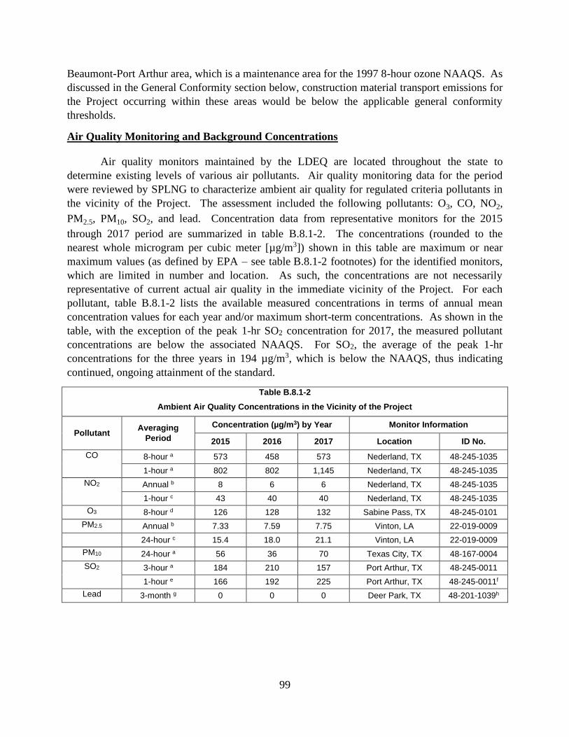
99
Beaumont-Port Arthur area, which is a maintenance area for the 1997 8-hour ozone NAAQS. As
discussed in the General Conformity section below, construction material transport emissions for
the Project occurring within these areas would be below the applicable general conformity
thresholds.
Air Quality Monitoring and Background Concentrations
Air quality monitors maintained by the LDEQ are located throughout the state to
determine existing levels of various air pollutants. Air quality monitoring data for the period
were reviewed by SPLNG to characterize ambient air quality for regulated criteria pollutants in
the vicinity of the Project. The assessment included the following pollutants: O3, CO, NO2,
PM2.5, PM10, SO2, and lead. Concentration data from representative monitors for the 2015
through 2017 period are summarized in table B.8.1-2. The concentrations (rounded to the
nearest whole microgram per cubic meter [µg/m3]) shown in this table are maximum or near
maximum values (as defined by EPA – see table B.8.1-2 footnotes) for the identified monitors,
which are limited in number and location. As such, the concentrations are not necessarily
representative of current actual air quality in the immediate vicinity of the Project. For each
pollutant, table B.8.1-2 lists the available measured concentrations in terms of annual mean
concentration values for each year and/or maximum short-term concentrations. As shown in the
table, with the exception of the peak 1-hr SO2 concentration for 2017, the measured pollutant
concentrations are below the associated NAAQS. For SO2, the average of the peak 1-hr
concentrations for the three years in 194 µg/m3, which is below the NAAQS, thus indicating
continued, ongoing attainment of the standard.
Table B.8.1-2
Ambient Air Quality Concentrations in the Vicinity of the Project
Pollutant Averaging
Period
Concentration (µg/m3) by Year Monitor Information
2015 2016 2017 Location ID No.
CO 8-hour a 573 458 573 Nederland, TX 48-245-1035
1-hour a 802 802 1,145 Nederland, TX 48-245-1035
NO2 Annual b 8 6 6 Nederland, TX 48-245-1035
1-hour c 43 40 40 Nederland, TX 48-245-1035
O3 8-hour d 126 128 132 Sabine Pass, TX 48-245-0101
PM2.5 Annual b 7.33 7.59 7.75 Vinton, LA 22-019-0009
24-hour c 15.4 18.0 21.1 Vinton, LA 22-019-0009
PM10 24-hour a 56 36 70 Texas City, TX 48-167-0004
SO2 3-hour a 184 210 157 Port Arthur, TX 48-245-0011
1-hour e 166 192 225 Port Arthur, TX 48-245-0011f
Lead 3-month g 0 0 0 Deer Park, TX 48-201-1039h

100
Table B.8.1-2
Ambient Air Quality Concentrations in the Vicinity of the Project
Pollutant Averaging
Period
Concentration (µg/m3) by Year Monitor Information
2015 2016 2017 Location ID No.
µg/m3 = micrograms per cubic meter a 2nd highest measurement recorded for each year. b Annual average measurement recorded for each year. c 98th percentile measurement recorded for each year. d 4th highest 8-hour average measurement recorded for each year. e 99th percentile measurement recorded for each year. f 2017 value based on Station No. 48-245-1071 (Port Arthur, TX) data because data from Station No. 48-245-
0011 is invalid g Maximum 3-month measurement recorded for each year. h 2017 value based on Station No. 22-033-0009 (Baton Rouge, LA) data because data from Station No. 48-
201-1039 is invalid
Greenhouse Gases
The EPA has defined air pollution to include the mix of six long-lived and directly
emitted GHGs (CO2, CH4, N2O, hydrofluorocarbons, perfluorocarbons, and sulfur hexafluoride).
The EPA found that the current and projected concentrations of these six GHGs in the
atmosphere threaten the public health and welfare of current and future generations through
climate change.
GHG, including carbon dioxide (CO2,) methane (CH4), nitrous oxide (N2O),
hydrofluorocarbons, and perfluorocarbons, are naturally occurring pollutants in the atmosphere
and products of human activities, including burning fossil fuels. These gases are the integral
components of the atmosphere’s greenhouse effect that warms the earth’s surface and moderate
day/night temperature variation. In general, the most abundant GHGs are water vapor, CO2,
CH4, N2O, and O3. GHG produced by fossil-fuel combustion are CO2, CH4, and N2O. GHGs are
non-toxic and non-hazardous at normal ambient concentrations. Increased levels of all GHG
since the industrial age are the primary cause of warming of the global climate system since the
1950s. Emissions of GHGs are typically expressed in terms of CO2 equivalents (CO2e).
As with any fossil fuel-fired project or activity, the Project would contribute to GHG
emissions. The principle GHGs that would be produced by the project are CO2, CH4, and N2O.
Emissions of GHGs are quantified and regulated in units of CO2e. The CO2e unit of measure
takes into account the global warming potential (GWP) of each GHG over a specified timeframe.
The GWP is a ratio relative to CO2 that is based on the particular GHG’s ability to absorb solar
radiation as well as its residence time within the atmosphere. Thus, CO2 has a GWP of 1, CH4
has a GWP of 25, and N2O has a GWP of 298 on a 100-year timescale (EPA, 2017c). To obtain
the CO2e quantity, the mass of the particular compound is multiplied by the corresponding GWP
and the product is the CO2e for that compound. The CO2e value for each of the GHG
compounds is summed to obtain the total CO2e GHG emissions.
The EPA has expanded its regulations to include the emission of GHGs from major
stationary sources under the Prevention of Significant Deterioration (PSD) program. The EPA’s

101
current rules require that a stationary source that is major for a non-GHG-regulated New Source
Review (NSR) pollutant must also evaluate GHG emissions permit prior to beginning
construction of a new or modified major source with mass-based GHG emissions equal to or
greater than 100,000 tons per year (tpy) and significant net emission increases in units of CO2e
equal to or greater than 75,000 tpy. There are no NAAQS or other significant impact thresholds
for GHGs.
8.1.2 Regulatory Requirements for Air Quality
The Project would be potentially subject to a variety of federal and state regulations
pertaining to the construction and operation of air emission sources. The CAA, 42 USC 7401 et
seq., as amended in 1977 and 1990, and 40 CFR Parts 50 through 99 are the basic federal statutes
and regulations governing air pollution in the U.S. The LDEQ has the primary jurisdiction over
air emissions produced by stationary sources associated with the Project. The LDEQ is
delegated by the EPA to implement federal air quality programs. The LDEQ’s air quality
regulations are codified in LAC Title 33, Part III, Chapters 1 through 59. New facilities are
required to obtain an air quality permit before initiating construction.
The following sections summarize the applicability of various federal and state
regulations.
New Source Review/Prevention of Significant Deterioration
Separate pre-construction review procedures for major new stationary sources of air
pollution and major modifications of major sources have been established for projects that are
proposed to be built in attainment areas versus nonattainment areas. The pre-construction permit
program for new or modified major sources located in attainment areas is known as the PSD
program. This review process is intended to keep new air emission sources from causing
existing air quality to deteriorate beyond acceptable levels codified in the federal regulations.
Construction of major new stationary sources in nonattainment areas must be reviewed in
accordance with the nonattainment NSR regulations, which contain stricter thresholds and
requirements. Because the SPLNG facilities are located within an attainment area for all criteria
pollutants, nonattainment NSR does not apply. Rather, the Project must be reviewed to
determine applicability with the PSD program.
The PSD rule defines a major stationary source as any source with a potential to emit
(PTE) 100 tpy or more of any criteria pollutant for source categories listed in 40 CFR
§52.21(b)(1)(i) or 250 tpy or more of any criteria pollutant for source categories that are not
listed. In addition, with respect to GHG, the major source threshold for CO2e is 100,000 tpy.
The SPLNG terminal is an existing major stationary source operating under PSD Permit No.
PSD-LA-703(M6), issued on September 20, 2017 by the LDEQ.
Any change to a major stationary source that qualifies as a major modification under PSD
rules (40 CFR §52.21 and LAC 33:III.509) is subject to PSD permitting. A major modification
is defined as any physical change or change in the method of operation of a major stationary
source that would result in a significant emissions increase of a regulated NSR pollutant, and a

102
significant net emissions increase of that pollutant from the major stationary source. Emission
increases are compared against significant emission increase thresholds (100 tpy for CO; 40 tpy
for NOx, VOC, and SO2 each; 25 tpy for total suspended particulate, 15 tpy for PM10, and 10 tpy
for directly-emitted PM2.5; 75,000 tpy for CO2e) to assess PSD applicability; increases less than
the thresholds do not trigger PSD review. The Project, as a modification to the existing SPLNG
Terminal, must be evaluated to determine if this modification qualifies as “major,” requiring
PSD review.
The Project would result in physical changes to the SPLNG terminal. In order to
determine if these physical changes trigger PSD review, SPLNG compared the baseline actual
emissions against the potential emissions for those emission sources affected by the Project (i.e.,
the existing Enclosed Ground Marine Flare and pipeline fugitives). “Baseline actual emissions”
are the recent (past) emissions for the sources that are proposed to be modified (due to increased
emissions in the case of the Third Berth Project). Potential emissions are the maximum (future)
emissions from the modified sources under the Project. As shown in table B.8.1-3, the proposed
emission rate changes (i.e., potential emissions minus baseline actual emissions) associated with
the Project would not exceed the significant emission increase thresholds. Therefore, PSD
review would not be triggered by the Project. A permit application air quality analysis
addressing the revised emissions was submitted to the LDEQ in October 2018.
Table B.8.1-3
Major Stationary Source/Prevention of Significant Deterioration (PSD) Applicability Analysis – SPLNG Third
Berth Project
Pollutant a
Baseline Actual Emission Rates for Third Berth Project
Sourcesb (tpy)
Potential Emissions for
Third Berth Project Sources
(tpy)
Emission Rate
Changec (tpy)
Major Source Modification Significant
Emission Threshold (tpy)
PSD Netting Triggered?
PM10 2.24 2.46 0.22 15 No
PM2.5 2.24 2.46 0.22 10 No
NOx 24.02 26.38 2.36 40 No
SO2 <0.01 <0.01 <0.01 40 No
CO 109.51 120.28 10.77 100 No
VOC 8.38 11.25 2.87 40 No
CO2e N/A d N/A d N/A d 75,000 No d
a Projected emissions of other NSR/PSD-regulated pollutants are small to negligible.
b Third Berth Project-affected sources (Enclosed Ground Marine Flare and pipeline fugitives) at the SPLNG Terminal authorized under LDEQ Part 70 Permit No. 0560-00214-V6
c Because the emission rate changes (or increases) are below the relevant significant emission thresholds for all pollutants, PSD review is not triggered.
d N/A = Not applicable; CO2e threshold is only applicable if the major source threshold for another criteria pollutant is exceeded.
The V Operating Permit
Title V of the CAA requires states to establish an air quality operating permit program.
The requirements of Title V are outlined in the federal regulations in 40 CFR Part 70 and in the

103
state regulations in LAC 33:III.507. The operating permits required by these regulations are
often referred to as Title V or Part 70 operating permits.
Major sources (i.e., sources with a PTE greater than a major source threshold level) are
required to obtain a Title V operating permit. Title V major source threshold levels are 100 tpy
for any regulated air pollutant (excluding any air pollutant regulated solely under Section 112 –
for HAPs – of the CAA); 10 tpy for an individual HAP; or 25 tpy for any combination of HAPs.
Additionally, facilities that have the potential to emit GHGs at a threshold level of 100,000 tpy
CO2e are also subject to Title V permitting requirements.
The SPLNG terminal is an existing major source subject to the Title V permitting
program, operating under Part 70 Permit No. 0560-00214-V6, issued by the LDEQ on September
20, 2017. SPLNG submitted an application to the LDEQ in October 2018 to modify the Part 70
permit for the Project.
New Source Performance Standards
New Source Performance Standards (NSPS) regulations (40 CFR Part 60) establish
pollutant emission limits and monitoring, reporting, and recordkeeping requirements for various
emission sources based on source type and size. These regulations apply to new, modified, or
reconstructed sources. No NSPS requirements were determined to be applicable to the Project-
affected sources (although SPLNG is required by their Part 70 and PSD permits to comply with
the NSPS general requirements under 40 CFR §60.18 as best available control technology
[BACT]).
National Emission Standards for Hazardous Air Pollutants
The National Emission Standards for Hazardous Air Pollutants codified in 40 CFR Parts
61 and 63 regulate HAP emissions. Part 61 was promulgated prior to the 1990 Clean Air Act
Amendments (CAAA) and regulates specific HAPs, such as asbestos, benzene, beryllium,
inorganic arsenic, mercury, radionuclides, and vinyl chloride.
The 1990 CAAA established a list of 189 HAPs, while directing EPA to publish
categories of major sources and area sources of these HAPs, for which emission standards were
to be promulgated according to a schedule outlined in the CAAA. These standards, also known
as the Maximum Achievable Control Technology standards, were promulgated under Part 63.
The 1990 CAAA defines a major source of HAPs as any source that has a PTE of 10 tpy for any
single HAP or 25 tpy for all HAPs in aggregate. Area sources are stationary sources that do not
exceed the thresholds for major source designation.
The SPLNG terminal is an existing major source of HAPs. No National Emission
Standards for Hazardous Air Pollutants requirements were determined to be applicable to the
Project-affected sources.
104
Greenhouse Gas Reporting Rule
Subpart W under 40 CFR Part 98, the Mandatory Greenhouse Gas Reporting Rule,
requires petroleum and natural gas systems that emit 25,000 metric tons or more of CO2e per
year to report annual emissions of GHG to the EPA. “LNG storage” and “LNG import and
export equipment” are industry segments specially included in the source category definition of
petroleum and natural gas systems. Equipment subject to reporting includes storage of LNG,
liquefaction of natural gas, and regasification of LNG.
Emissions of GHGs associated with the construction and operation of the Project were
calculated. In addition, GHG emissions were converted to total CO2e emissions based on the
GWP of each pollutant. Although the reporting rule does not apply to construction emissions,
construction emissions have been included in this document for accounting and disclosure
purposes. GHG emissions from operation of the Project would be included as part of the GHG
reporting for the SPLNG terminal.
Chemical Accident Prevention Provisions
The chemical accident prevention provisions, codified in 40 CFR Part 68, are federal
regulations designed to prevent the release of hazardous materials in the event of an accident and
minimize potential impacts if a release does occur. The regulations contain a list of substances
(including methane, propane, and ethylene) and threshold quantities for determining applicability
to stationary sources. If a stationary source stores, handles, or processes one or more substances
on this list in a quantity equal to or greater than specified in the regulation, the facility must
prepare and submit a risk management plan (RMP). An RMP is not required to be submitted to
the EPA until the chemicals are stored onsite at the facility.
If a facility does not have a listed substance on-site, or the quantity of a listed substance is
below the applicability threshold, the facility does not have to prepare an RMP. However, if
there is any regulated substance or other extremely hazardous substance onsite, the facility still
must comply with the requirements of the General Duty Clause in Section 112(r)(1) of the 1990
CAAA.
Stationary sources are defined in 40 CFR Part 68 as any buildings, structures, equipment,
installations, or substance-emitting stationary activities which belong to the same industrial
group, that are located on one or more contiguous properties, are under control of the same
person (or persons under common control), and are from which an accidental release may occur.
However, the definition also states that the term stationary source does not apply to
transportation, including storage incidental to transportation, of any regulated substance or any
other extremely hazardous substance. The term transportation includes transportation subject to
oversight or regulation under 49 CFR Parts 192, 193, or 195. Based on these definitions, the
Project facilities are subject to 49 CFR Part 193 and would not be required to prepare an RMP.

105
General Conformity
A general conformity analysis must be conducted by the lead federal agency if a federal
action would result in the generation of emissions that would exceed the general conformity
applicability threshold levels of the pollutants(s) for which an AQCR is in nonattainment.
According to Section 176(c)(1) of the CAA (40 CFR §51.853), a federal agency cannot approve
or support any activity that does not conform to an approved SIP. Conforming activities or
actions should not, through additional air pollutant emissions:
• cause or contribute to new violations of the NAAQS in any area;
• increase the frequency or severity of an existing violation of any NAAQS; or
• delay timely attainment of any NAAQS or interim emission reductions.
General Conformity assessments must be completed when the total direct and indirect
emissions of a planned project would equal or exceed the specified pollutant applicability
emission thresholds per year in each nonattainment area.
As previously discussed in section B.8.1.1, the Project facilities would be located in an
area currently designated by EPA as attainment of all NAAQS or unclassifiable for all criteria
pollutants. Operating emissions for these facilities would be located entirely within designated
unclassifiable/attainment areas for all criteria air pollutants and would be subject to evaluation
under the NSR permitting program, and these emissions are not subject to General Conformity
regulations. However, during the construction phase of the Project, barges carrying equipment
and materials would travel periodically through the Beaumont-Port Arthur and the HGB areas to
the SPLNG Terminal construction dock via the Gulf Intracoastal Waterway. (As discussed
earlier, the HGB area is a nonattainment area for the 8-hour ozone NAAQS and the Beaumont-
Port Arthur area is a maintenance area for the 8-hour ozone NAAQS). The construction barge
traffic emissions associated with travel in the HGB and Beaumont-Port Arthur ozone
nonattainment and maintenance areas are subject to evaluation under General Conformity
regulations.
The relevant general conformity pollutant thresholds for the HGB ozone nonattainment
area are 25 tpy of NOx and VOC (ozone precursors) for the portion of the Project construction-
related barge/tug emissions located in that nonattainment area (which is still classified as
“severe” for the 1997 8-hour ozone standard).
SPLNG estimated emissions from tug vessels that push the barges using EPA-sponsored
marine vessel emissions estimation guidance. The emissions were apportioned between the
HGB ozone nonattainment area, Beaumont-Port Arthur maintenance area, and the adjacent
unclassifiable/attainment areas based on the emissions generated during the time spent traveling
through each of these areas. SPLNG estimated that the total potential direct and indirect
emissions of NOx and VOC from the Project construction-related activity (i.e., construction
barge/tug travel in the HGB ozone nonattainment and Beaumont-Port Arthur maintenance areas)

106
for each year in the 2020 through 2022 period would be less than 1 tpy for each year;11 therefore,
a General Conformity Determination is not required for the Project.
State Air Quality Requirements
In addition to the federal regulations identified above, the LDEQ has its own air quality
regulations, codified in LAC Title 33, Part III, Chapters 1 through 59. The state requirements
potentially applicable to the Project are discussed below:
• LAC 33:III Chapter 5 – Permit Procedures. This chapter outlines the construction
and operating permit procedures for major and subject non-major sources of air
pollution in Louisiana. More information on the construction (NSR) and operating
(Title V) permitting for the Project specifically is found in earlier sections of this
document.
• LAC 33:III Chapter 9 – General Regulations on Control of Emissions and Emission
Standards. The SPLNG stationary emission sources are subject to the general
regulations outlined in in this chapter. As such, SPLNG is required to include the
emissions from these sources (including any additional emissions from the Project-
affected stationary sources) in an annual emission summary report and to submit
written reports of any “unauthorized discharges” of an air pollutant from these
sources.
• LAC 33:III Chapter 11 – Control of Emissions of Smoke. This chapter outlines
opacity limits for combustion units and flares, limitations on outdoor burning, and the
prohibition on visibility impairment on public roads. The existing Enclosed Ground
Marine Flare and Marine Flare No. 1 (the only Project sources subject to this
requirement) would continue to comply with the opacity limits and notification
requirement of this chapter.
• LAC 33:III Chapter 13 – Emission Standards for Particulate Matter. This chapter
applies to any operation, process, or activity from which PM is emitted, and requires
that all reasonable measures be taken to prevent generation of fugitive PM emissions.
The existing Enclosed Ground Marine Flare and Marine Flare No. 1 would continue
to comply with the opacity limits of this chapter.
• LAC 33:III Chapter 15 – Emission Standards for Sulfur Dioxide. This chapter applies
to existing or new sulfuric acid production units, existing or new sulfur recovery
plants, and all other single point sources that emit or have the potential to emit 5 tpy
or more of SO2. Because none of the Project-affected sources emit or have the
potential to emit 5 tpy of SO2, the requirements of this chapter would continue to not
be applicable.
11 SPLNG Third Berth Expansion Project Resource Report 9 – Air and Noise Quality (Table 9.2-8), Sabine Pass
LNG, L.P., October 2018, Docket No. CP19-11-000.
107
• LAC 33:III Chapter 21 – Control of Emissions of Organic Compounds. This chapter
regulates organic compound emissions from various sources; however, the only
Project sources subject to this chapter are fugitive components in VOC service. LAC
33:III.2111 requires that pumps and compressors handling VOC with a true vapor
pressure greater than 1.5 pounds per square inch absolute at handling conditions be
equipped with mechanical seals or other equivalent equipment approved by the
LDEQ. The affected Project fugitive components would be subject to and comply
with this requirement.
• LAC 33:III Chapter 29 – Odor Regulations. This chapter prohibits the discharge of
odorous substances that cause a nuisance at or beyond the property line. SPLNG
would continue to operate the terminal, including Project-affected sources, in a
manner that would not cause an odorous nuisance beyond the property line.
• LAC 33:III Chapter 51 – Comprehensive Toxic Air Pollutant Emission Control
Program. This chapter applies to a major source of any toxic air pollutant(s) (TAPs)
listed in LAC 33:III.5112, Table 51.2 or Table 51.3. A major source is defined as a
source that has the potential to emit, in the aggregate, 10 tpy or more of any
individual LDEQ-listed TAP, or 25 tpy or more of any combination of LDEQ-listed
TAPs. Emissions from the combustion of Group 1 virgin fossil fuels are exempt from
the requirements of this chapter, per LAC 33:III.5105.B. After excluding such
combustion emissions, the SPLNG Terminal is not a major source of HAPs and is not
subject to the requirements of this chapter. Emissions from Project-affected sources
would not change the non-applicable status of the SPLNG Terminal.
• LAC 33:III Chapter 56 – Prevention of Air Pollution Emergency Episodes. This
chapter requires the preparation of standby plans for the reduction of emissions
contributing to high pollution levels and to activate such plans when the LDEQ
declares an Air Pollution Alert, Air Pollution Warning, or Air Pollution Emergency.
SPLNG would continue to comply with these requirements.
• LAC 33:III Chapter 59 – Chemical Accident Prevention and Minimization of
Consequences. This chapter incorporates, by reference, 40 CFR Part 68 (Chemical
Accident Prevention Provisions). As discussed earlier, the SPLNG Terminal is
subject to 49 CFR Part 193; therefore, 40 CFR Part 68 and LAC 33:III Chapter 59 do
not apply. The Project would not change the non-applicable status of the SPLNG
Terminal.
8.1.3 Construction Emissions and Impacts
Construction Emissions and Impacts
Construction of the Project would result in short-term increases in emissions of some air
pollutants due to the use of equipment powered by diesel fuel or gasoline and the generation of

108
fugitive dust due to the disturbance of soil and other dust-generating activities. More
specifically, the construction activities that would generate air emissions include:
• site preparation (vegetation clearing, trenching, land contouring, foundation
preparation, etc.);
• construction/installation of Project facilities;
• operation of off-road construction equipment and trucks during construction;
• operation of marine vessels (e.g., equipment barges/tugs) during construction; and
• workers’ vehicles used for commuting to and from the construction site and delivery
trucks (i.e., on-road vehicles).
The total period of construction for the Project facilities is estimated by SPLNG to be
about 30 months.
Emission increases associated with the Project construction activities would have short-
term, localized impacts on air quality. These emissions are not subject to the air quality
permitting requirements that apply to emissions from operation of stationary sources associated
with the Project. It should be noted that there are no residential or sensitive populations within
1 mile of the Project site. Nevertheless, the construction-related emission rates are discussed in
this section as a means of identifying potential air quality concerns associated with the
construction phase of the Project and to assist in developing mitigation.
The amount of fugitive dust generated in an area under construction would depend on
numerous factors including:
• nature and intensity of the construction activity;
• speed, weight, and volume of vehicular traffic;
• size of area disturbed;
• amount of exposed soil and soil properties (silt and moisture content); and
• wind speed.
Fugitive dust would be produced primarily during site preparation activities, when the
Project area would be cleared of debris, leveled, and graded. Site preparation activities for the
Project would include land clearing, grading, filling, and placement of aggregate materials (e.g.,
for laydown areas and access roads). Site preparation activities would generate fugitive dust
from earthmoving and movement of construction equipment over unpaved surfaces and tailpipe
emissions from construction equipment and vehicle engines. Site preparation equipment would
include bulldozers, excavators, compactors, graders, and other mobile construction equipment.
On-road truck traffic (e.g., supply trucks) and worker commuter vehicles at the Project sites
would also generate fugitive dust from travel on paved and unpaved surfaces. SPLNG intends to
conduct periodic watering of construction areas and unpaved roads to reduce the generation of
fugitive dust.

109
The construction equipment and trucks/vehicles would be powered by internal
combustion engines that would generate PM10, PM2.5, SO2, NOx, VOC, and CO emissions.
These emissions would be generated by a variety of diesel-fueled (primarily) equipment,
including off-road sources (e.g., bulldozers, excavators), on-road sources (e.g., construction
worker vehicles, buses, miscellaneous trucks), and marine vessels (e.g., barges/tugs). Most of
the on-road vehicles would likely burn gasoline, although supply trucks and some worker pickup
trucks would burn ultra-low-sulfur diesel fuel.
A main component of Project construction would involve the dredging of a new berth
pocket located adjacent and southeast of the two existing SPLNG marine berths along the Sabine
Pass Channel. In conducting this work, emissions would be generated by a cutter suction dredge
and mechanical bucket dredger and various support vessels (e.g., tugboats, barges), as well as the
booster pump used to move dredge material, via floating pipeline, to the DMPA. Construction of
the Project would also include a new platform, LNG loading lines and cooldown lines, and LNG
loading arms, as well as buildings (and associated foundations) and a hydraulic gangway. No
new LNG storage tanks are proposed as part of the Project. Construction equipment to be used
for the Project would include cranes, forklifts, welders, manlifts, and generators (for various
duties, such as pumping, lighting, etc.).
Project construction materials would be delivered primarily by barge to the existing
construction dock at the SPLNG Terminal. SPLNG estimates that a total of approximately
70 marine deliveries over the construction period would be needed for construction materials
shipped from the Houston and New Orleans areas. Barge/tug operations would result in fuel
combustion emissions from diesel-fired engines.
SPLNG developed an inventory of off-road equipment and vehicles, on-road vehicles,
and expected activity levels (either hours of operation or miles travelled) based on the expected
duration of Project construction for the purposes of calculating emissions. The level of activity
for each piece of construction equipment was combined with the relevant EPA emission factors
(e.g., MOVES2014a model) to estimate the annual emissions. Fuel combustion emissions from
barges/tugs were calculated using engine sizes and loads, activity levels, and emission factors
based on EPA-sponsored marine vessel emissions estimation guidance.12 SO2 emission
estimates were based on the use of ultra-low-sulfur diesel fuel. Annual emissions for on-road
vehicles were calculated using MOVES2014a model emission factors and estimates of total
annual offsite and onsite travel distance for worker/commuter vehicles and construction material
delivery trucks. Fugitive dust emission estimates associated with land disturbance activities for
the Project were based on an estimate of total disturbed acreage and the use of emission factors
based on Western Governors’ Association-sponsored guidance,13 including an emission
reduction or control factor of 50 percent for application of dust suppressants (e.g., water).
12 EPA’s Current Methodologies in Preparing Mobile Source Port-Related Emission Inventories (Final Report),
April 2009. 13 Western Governors Association’s WRAP Fugitive Dust Handbook, September 7, 2006.

110
The total criteria air pollutant and GHG (as CO2e) emissions associated with
construction-related activities for the Project are summarized in table B.8.1-4. These totals
include fuel combustion emissions (from on-shore equipment and marine vessels) as well as
fugitive dust (i.e., particulate) emissions. The total PM10 and PM2.5 emissions shown
table B.8.1-4 are mainly the result of fugitive dust-generating activities, with most of the fugitive
dust emissions associated with land disturbance activities. Note that the estimated annual
construction emissions are based on the latest available information on Project schedule; and the
timing and magnitude of annual emissions could vary based on when construction activities
actually occur, which is dependent on business-related and other (e.g., regulatory) factors.
Table B.8.1-4
Annual Project Construction Emissions (tpy)
Year Pollutant
PM10 PM2.5 NOx CO SO2 VOC HAPs CO2e a
2020 337.5 95.0 1,286.3 154.5 2.2 49.8 2.0 29,563
2021 331.3 42.5 210.0 79.2 1.9 9.2 1.1 15,454
2022 345.2 36.6 68.8 47.3 3.0 3.1 0.8 7,634
Total Construction Period Emissions
1,014.0 174.1 1,565.1 281.1 7.1 62.1 3.9 52,651
a Metric tons
Emissions over the construction period would increase pollutant concentrations in the
vicinity of the Project. However, the effect on ambient air quality would vary with time due to
the intensity of activities during the construction period, the mobility of the sources, and the
variety of emission sources. There may be localized, temporary minor to moderate elevated
levels of fugitive dust and tailpipe emissions in the vicinity of construction areas during periods
of peak construction activity. In addition, there would be overlap of emissions from construction
activities for the Project and construction and commissioning activities for the last liquefaction
train (SPLNG Expansion Project Train 6) of the existing SPLNG Terminal. The potential impact
of the overlap of emissions from construction and operations are discussed in the Operations
Impacts Assessment section. Considering all of these factors, we determine that construction of
the Project would not have a long-term, permanent effect on air quality in the area.
During the concurrent construction periods, the higher emission levels could result in
greater impacts to air quality compared with that for the Project alone. These higher
concentrations would not be persistent due to the dynamic and fluctuating nature of construction
activities within a day, week, or month.
Construction Emissions Mitigation Measures
As discussed previously, fugitive dust accounts for the primary PM emissions during the
construction period for the Project. Therefore, fugitive dust controls would play an important
role in reducing potential effects on air quality in the Project area. Project construction activities
would be subject to LAC 33:III.1305, which requires that all reasonable precautions (including
application of dust suppressants) be taken to prevent fugitive dust generation.

111
In addition to the regulation-based precautions, SPLNG developed a Fugitive Dust
Control Plan (FDCP), committing to additional measures to reduce fugitive dust emissions.
FERC staff reviewed the FDCP and finds it acceptable. Measures outlined in the FDCP, include
the following:
• use of a dedicated water truck to apply water to most areas (access roads, construction
dock, staging and laydown areas, and designated parking areas) within the Project
boundary;
• ensure that dump trucks and other open-bodied trucks hauling soil or other dusty
materials to or from the Project site are covered;
• use of signage to direct construction vehicle traffic to designated roads;
• enforcement of a 15-mph speed limit on unsurfaced roads;
• use of gravel or larger rock at construction entrance and exit locations; and
• measures to clean paved roads upon mud or dirt track-out.
SPLNG would minimize vehicular exhaust and crankcase emissions from gasoline- and
diesel-fired engines by complying with applicable EPA mobile source emission performance
standards and by using equipment manufactured to meet these standards. Additionally, SPLNG
would be expected to implement the following work practices:
• Maintain construction equipment in accordance with manufacturers’
recommendations. Maintenance and tuning of all construction-related equipment
would be conducted in accordance with the original equipment manufacturers’
recommendations; and
• Minimize engine idling to the extent practicable. SPLNG would instruct Project
construction personnel to minimize the idle time of equipment to 5 minutes or less
when not in active use. SPLNG’s expectations concerning minimizing on-site idling
would be communicated to construction personnel during safety/environmental
training sessions and enforced by construction supervisors and inspectors. Also,
consistent with industry practice, unmanned equipment would be turned off and
would not be left idling.
8.1.4 Operation Emissions Impacts and Mitigation
Operating Air Emissions
Operation of the SPLNG Third Berth would result in additional air emissions from
increasing the emissions at existing marine flare and additional marine (e.g., LNGCs) traffic.
No new stationary emission sources have been proposed by SPLNG for the Project. Due
to the additional LNGCs calling at the Third Berth that would undergo the cool-down process,
the Project would result in an increase in potential annual emissions of criteria air pollutants,
GHGs, and HAPs from combustion of additional cool-down process gases in the currently-

112
permitted Enclosed Ground Marine Flare and its backup, Marine Flare No. 1. (Note that the
Marine Flare No. 1 would only be utilized when the Enclosed Ground Marine Flare is not
operational; therefore, emissions from the Marine Flare No. 1 would be equal to or less than the
emissions from the Enclosed Ground Marine Flare.) Also, potential fugitive VOC and GHG
emissions would increase due to the additional components (e.g., valves) associated with new
piping and other infrastructure to transport LNG to the Third Berth. These increased
operational-phase emissions would be permanent.
Table B.8.1-5 provides a summary of the total annual criteria air pollutant, GHG (as
CO2e), and HAP emission rates for routine operations of the SPLNG Terminal, including the
authorized emissions for Trains 1-6, proposed emissions modifications for Trains 1-6 of the
authorized SPLNG terminal, and proposed emissions for the Third Berth Project alone, including
associated marine vessels. In table B.8.1-5, the Third Berth Project emissions are composed of
the additional emissions from the existing Enclosed Ground Marine Flare and pipeline
components (fugitives) at the SPLNG Terminal once the Third Berth is in full operation. The
additional marine flare and fugitive emissions associated with the Third Berth Project would be
generated by the additional LNGCs undergoing cool-down. (Note that this analysis addresses the
additional 180 LNGCs per year associated with the Project; however, only 8 of these 180 ships
will undergo cool-down and emit to the Enclosed Ground Marine Flare.)
Table B.8.1-5
Annual Emissions (tpy) for Operation of Existing and Proposed SPLNG Terminal Sources
Emission Source
Pollutant
PM10 PM2.5 NOx CO SO2 VOC Total HAPs
CO2e a
SPLNG Terminal
Liquefaction Trains 1-6 (Authorized)b
187.42 187.40 6,185.40 5,213.92 38.24 334.18 10,797,256
Marine Vesselsc 17.19 16.05 342.65 302.37 92.26 31.26 40,945
Proposed Changes – Trains 1-6b
+0.44 +0.40 +324.09 +15.31 <+0.01 +8.05 -29,600
Third Berth Project
Additional Emissions from SPLNG Terminal
0.22 0.22 2.36 10.77 <0.01 1.78 5,587
Marine Vessels 11.8 11.1 235.4 294.2 72.3 48.6 40,362
Facility Total 217.1 215.2 7,089.9 5,836.6 202.8 423.8 83.21d 10,854,550

113
Table B.8.1-5
Annual Emissions (tpy) for Operation of Existing and Proposed SPLNG Terminal Sources
Emission Source
Pollutant
PM10 PM2.5 NOx CO SO2 VOC Total HAPs
CO2e a
a Metric tons per year b Resource Report 9, Appendix 9D: Title V Air Permit Significant Modification/Reconciliation and PSD Permit
Reconciliation Application, Table 1-5 (but excluding incremental contribution from Third Berth operation) (submitted to the Louisiana DEQ on October 29, 2018). The Louisiana DEQ application included information for two independent capital projects: 1) the new Third Berth Project, and 2) equipment additions and improvements to existing equipment for previously-permitted Trains 1-6. Some of the equipment changes for Trains 1-6 resulted in the proposed modifications to permitted emissions.
c Resource Report 9, Appendix 9A, Table 9.A.1.31. d Attachment 24a, Table 1 of SPLNG's Response to Comments, submitted to FERC on July 26, 2019.
During operation of the SPLNG Third Berth, LNGCs and supporting marine vessels
would routinely generate air emissions. The calculation assumptions/methodologies and
emission factors used by SPLNG to develop emission rates for the marine vessels are consistent
with those used for the existing SPLNG Terminal marine vessel operations.
The basis for estimating marine vessel emissions associated with the Project operation is
based on the post-Project SPLNG Terminal capacity (for all three berths combined) increasing
from 400 to 580 LNGCs per year. For the purposes of estimating emissions, SPLNG assumed
that 194 LNGs (580/3, rounded up to the next whole ship) would call at the Third Berth
annually.
Marine vessel emissions are quantified for operation in transit within state territorial
waters, for maneuvering to/from the pier, and for hoteling at the pier. LNGC transiting would
occur over a 6-hour time period for each ship call (three hours arriving and three hours
departing). LNGC maneuvering around the pier would occur over a 2-hour time period for each
ship call (1 hour arriving and 1 hour departing) with the assistance of four tugboats for part of
each hour. LNGCs also would employ bow thrusters (powered by auxiliary engines) to assist in
maneuvering around the pier. While the LNGC is docked at the pier, emissions would be
generated by carrier hoteling operations for an approximate representative time period of 20
hours. SPLNG analyzed emissions from the hoteling and maneuvering operations for the
LNGCs assuming that the power requirements would be met through use of either a steam
turbine, slow speed diesel (SSD) engine, or dual fuel diesel-electric engine. SPLNG estimated
LNGC maneuvering emissions assuming a representative main engine size/rating of 41,013
kilowatts. In addition to these power generation systems/combustion units, emissions from use
of a Gas Combustion Unit and auxiliary boilers on the LNGCs having such equipment were
accounted for by SPLNG. Emissions from the Gas Combustion Unit and auxiliary boilers could
be generated by LNGCs in transit to and maneuvering and hoteling at the Third Berth. The
analysis assumes primarily natural gas as fuel, although use of marine gas oil for maneuvering
operations with a SSD engine was also evaluated.
According to SPLNG, the Coast Guard has delegated authority for security escort of each
LNGC to the local Sheriff’s department. Based on historical site experience, the Sheriff’s
security vessel would escort the LNGCs about 80 percent of the time, and only for the last 30

114
minutes of each LNGC transit inbound and first 20 minutes of each LNGC transit outbound.
The security vessel utilized would be a pilot-type boat equipped with an engine rated at 300 hp.
Although SPLNG did not calculate security vessel emissions for the Project due to the small
vessel engine and limited vessel operation for each LNGC call, SPLNG demonstrated that the
maximum expected annual emissions would be no greater than 13 percent of the security vessel
emissions calculated in support of the Sabine Pass Expansion Project (due to conservative
assumptions made for the emission calculations for that project).
Under CFR 33.165.819, the Coast Guard has mandated that the Sabine Pass LNG
mooring basins are designated as fixed security zones whenever LNG carriers are moored
within them. The SNND has statutory responsibility and authority for waterway security in
Jefferson County under Chapters 49 and 60 of the Texas Water Code and serves as the local
government waterway security program manager. The mooring basin security zone would be
enforced by the Coast Guard under the CFR process and relies on ad hoc patrols by SNND
and/or local Coast Guard unit, on a risk-based basis. Initial discussions with the Coast Guard
COTP, is that, the CFR regulation would be updated to further include the coordinates of the
Third Berth mooring basin once operational. Expectations from both Coast Guard and SNND
are that the existing security processes would be implemented similarly for the Third Berth.
The SPLNG Facility Security Plan, which is required under the U.S. Marine Transportation Act
of 2002 would be updated as part of the Third Berth implementation plan and submitted and
agreed with the Coast Guard prior to the new berth placed into service.
SPLNG’s emission calculations for marine vessels are based on a representative set of
engine emission factors for each phase of vessel operation (i.e., transiting, maneuvering, and
hoteling). The sources of emission factors are: 1) EPA emissions estimation guidance
documents14; 2) engine manufacturer/vendor data for NOx emissions from natural gas-fired
LNGC engines; 3) International Convention for the Prevention of Pollution from Ships (or
MARPOL) Annex VI standards (Tiers I and II) for NOx emissions from diesel-fired LNGC
engines; and 4) EPA Tier 4 exhaust emissions standards (Category 1 engines) for NOx, PM, and
VOC emissions from tugboat engines. Per EPA guidance, low load adjustment factors are
applied to the emission factors for the LNGC operating scenarios with SSD engines. For marine
vessel operation on diesel or marine gas oil fuel, SPLNG’s SO2 emission calculations are based
on emission factors assuming use of fuel oil with a sulfur content of 0.1 percent, which is
consistent with the requirements of the MARPOL Annex VI standards for the North America
Emission Control Area.
Table B.8.1-6 presents a summary of the estimated annual criteria air pollutant and GHG
(as CO2e) emissions associated with 1) LNGCs and tugboats maneuvering to the pier; and 2)
LNGCs hoteling at the pier. According to SPLNG, no tugboats would be idling without shore
power (i.e., no fuel combustion in tugboat engines) while the LNGC is maneuvering and
hoteling. However, under this scenario, the tugboats would either be maneuvering to assist the
LNG carrier or docked and on shore power (i.e., no air emissions). Note that the emissions
14 EPA’s AP-42 – Compilation of Air Pollutant Emission Factors, Volume I: Stationary Point and Area Sources and
Current Methodologies in Preparing Mobile Source Port-Related Emission Inventories (Final Report), April 2009.

115
associated with tugboats maneuvering are already included in table B.8.1-6. SPLNG confirms
that the tugboats would meet the EPA Tier IV engine NOx emission standards and the required
NOx emissions standards of MARPOL Annex VI as required by the International Maritime
Organization. Table B.8.1-7 presents a summary of the estimated annual criteria air pollutant
and GHG (as CO2e) emissions for LNGCs transiting in state waters. The emissions presented in
Tables B.8.1-6 and B.8.1-7, which are not subject to consideration/review under the federal/state
air permitting programs for stationary sources, are based on 194 carrier calls per year.
Table B.8.1-6
Annual Emissions (tpy) for Marine Vessels Associated with Maneuvering and Hoteling Operations
Emission Source Pollutant
PM10 PM2.5 NOx CO SO2 VOC CO2e a
LNG Carriers b 0.88 0.88 77.76 113.84 14.45 34.47 13,154
Tugs 1.33 1.33 59.71 165.87 1.39 6.30 23,610
Total Emissions 2.2 2.2 137.5 279.7 15.8 40.8 36,764
a Metric tons per year b Emissions included for on-board Gas Combustion Unit and auxiliary boilers
Table B.8.1-7
Annual Emissions (tpy) for Marine Vessels Associated with Transiting in State Waters
Emission Source Pollutant
PM10 PM2.5 NOx CO SO2 VOC a CO2e b
LNG Carriers c 9.62 8.90 97.89 14.50 56.48 7.80 3,598
a Represents hydrocarbon emission rate (conservative) b Metric tons per year c Emissions included for on-board Gas Combustion Unit and auxiliary boilers
Operations Emissions Mitigation Measures
BACT was established for the flares and component fugitive sources in past permitting
actions (as recently as September 2017) for the SPLNG Terminal. The Project would continue to
use BACT in the operation of the Enclosed Ground Marine Flare and Marine Flare No. 1.
SPLNG would ensure the flares are operated with good combustion practices in continual
compliance with NSPS requirements (40 CFR §60.18), maintaining a flame when vent gas is
routed to the flares. Although BACT is not triggered for the Project, SPLNG would apply its
current VOC BACT requirements (use of mechanical seals or equivalent for substances with a
true vapor pressure of 1.5 psia or greater) and GHG BACT practices (application of leak
detection and repair program) to the component fugitive emissions associated with the Project.
The BACT-based emissions standards and operating practices are consistent with NSPS and
LDEQ standards and practices applicable to these emission sources.

116
Operations Impact Assessment
To provide a more thorough evaluation of the potential impacts on air quality in the
vicinity of the Project, SPLNG conducted a quantitative assessment of air emissions, including
marine vessel emissions, associated with operation of the Third Berth Project and the existing
SPLNG Terminal. This assessment used EPA- and/or LDEQ-recommended pollutant dispersion
modeling methods to predict off-site (i.e., ambient) concentrations in the vicinity of the Project
for comparison against applicable federal and state ambient air quality standards.
Although the Project is not subject to review under the PSD permitting program based on
the potential emissions increases, an air quality impact analysis was required by FERC. The
focus of the impact analysis was assessing compliance with the NAAQS. The air quality impacts
analysis was conducted by SPLNG per U.S. EPA and LDEQ modeling guidelines. In
conducting the air quality impact analysis to address FERC requirements, SPLNG built upon the
previous analysis conducted to satisfy LDEQ permitting/modeling requirements, addressing
emissions from on-shore stationary sources (including the existing SPLNG Terminal emission
sources) as well as LNGCs maneuvering to and hoteling at the pier and supporting marine vessel
(e.g., tugboats) activities. Because the Project would not be subject to PSD review, offsite
emission sources were not included in the modeling. Regarding modeled Project PM2.5
emissions, SPLNG utilized interpollutant offset ratios to account for secondary PM2.5 emissions
formation, which had been approved by the LDEQ for use in calculating secondary PM2.5
emissions formation for the existing SPLNG sources.
SPLNG’s accounting of marine vessel emissions in the impact analysis assumed
conservative operating scenarios for LNGCs and tug boats at Berth 1, Berth 2, and Berth 3 (i.e.,
the Third Berth). For a worst-case operating scenario for the three berths, SPLNG
conservatively assumed that three LNGCs would be operating simultaneously at the three berths,
with hoteling and maneuvering activities occurring within the same hour for all three carriers,
concurrent with two maneuvering tugboats at Berths 1 and 2 and two maneuvering tugboats at
Berth 3. SPLNG also examined a worst-case operating scenario for Berth 3 in particular,
conservatively assuming that four tugboats would be maneuvering during the same hour as a
hoteling carrier at that berth.
The results of the impact analysis, shown in table B.8.1-8, indicate that emissions
associated with the Project facilities, including stationary and marine sources, would be below
the NAAQS. Therefore, we conclude that construction and operation of the proposed Project
would not have a significant impact on air quality.
Table B.8.1-8
Summary of Air Quality Impact Analysis Results
Pollutant Averaging
Period
Model-Predicted Concentration
(µg/m3)
Background Concentration
(µg/m3) a
Total Concentration
(µg/m3)
NAAQS (µg/m3)
NO2 1-hour 151.0 35.7 186.7 188
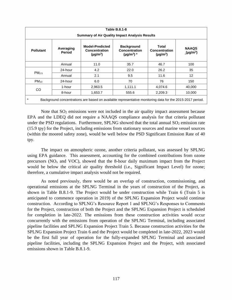
117
Table B.8.1-8
Summary of Air Quality Impact Analysis Results
Pollutant Averaging
Period
Model-Predicted Concentration
(µg/m3)
Background Concentration
(µg/m3) a
Total Concentration
(µg/m3)
NAAQS (µg/m3)
Annual 11.0 35.7 46.7 100
PM2.5 24-hour 4.2 22.0 26.2 35
Annual 2.1 9.5 11.6 12
PM10 24-hour 6.0 70 76 150
CO 1-hour 2,963.5 1,111.1 4,074.6 40,000
8-hour 1,653.7 555.6 2,209.3 10,000
a Background concentrations are based on available representative monitoring data for the 2015-2017 period.
Note that SO2 emissions were not included in the air quality impact assessment because
EPA and the LDEQ did not require a NAAQS compliance analysis for that criteria pollutant
under the PSD regulations. Furthermore, SPLNG showed that the total annual SO2 emission rate
(15.9 tpy) for the Project, including emissions from stationary sources and marine vessel sources
(within the moored safety zone), would be well below the PSD Significant Emission Rate of 40
tpy.
The impact on atmospheric ozone, another criteria pollutant, was assessed by SPLNG
using EPA guidance. This assessment, accounting for the combined contributions from ozone
precursors (NOx and VOC), showed that the 8-hour daily maximum impact from the Project
would be below the critical air quality threshold (i.e., Significant Impact Level) for ozone;
therefore, a cumulative impact analysis would not be required.
As noted previously, there would be an overlap of construction, commissioning, and
operational emissions at the SPLNG Terminal in the years of construction of the Project, as
shown in Table B.8.1-9. The Project would be under construction while Train 6 (Train 5 is
anticipated to commence operation in 2019) of the SPLNG Expansion Project would continue
construction. According to SPLNG’s Resource Report 1 and SPLNG’s Responses to Comments
for the Project, construction of both the Project and the SPLNG Expansion Project is scheduled
for completion in late-2022. The emissions from these construction activities would occur
concurrently with the emissions from operation of the SPLNG Terminal, including associated
pipeline facilities and SPLNG Expansion Project Train 5. Because construction activities for the
SPLNG Expansion Project Train 6 and the Project would be completed in late-2022, 2023 would
be the first full year of operation for the fully-expanded SPLNG Terminal and associated
pipeline facilities, including the SPLNG Expansion Project and the Project, with associated
emissions shown in Table B.8.1-9.

118
Table B.8.1-9
SPLNG Terminal, Expansion Project (Trains 5 and 6), and Third Berth Combined Construction,
Commissioning, and Operation Emissions (tpy)
Year
Pollutant
PM10 PM2.5 NOx CO SO2 VOC CO2ea Total HAPs
2020b 808 319 7,424 5,288 156 431 9,651,507 91
2021c 839 271 6,369 5,221 158 391 9,639,405 90
2022d 779 266 6,349 5,538 173 422 9,917,186 87
2023e 228 226 7,257 6,086 227 467 11,074,899 91
______________________
a Metric tons b 2020 construction emissions for SPLNG Expansion Project Train 6 and Third Berth Project from Table 1 of
Attachment 24a of SPLNG's Response to Comments, submitted to FERC on July 26, 2019, plus operation emissions for SPLNG associated pipeline facilities from Table 2 of Attachment 24a, plus operation emissions for SPLNG Terminal from Table 1 of Attachment 24a (excluding all Train 6 and Third Berth operation emissions).
c 2021 construction emissions for SPLNG Expansion Project Train 6 and Third Berth Project from Table 1 of Attachment 24a of SPLNG's Response to Comments, submitted to FERC on July 26, 2019, plus operation emissions for SPLNG associated pipeline facilities from Table 2 of Attachment 24a, plus operation emissions for SPLNG Terminal from Table 1 of Attachment 24a (excluding all Train 6 and Third Berth operation emissions).
d 2022 construction emissions for SPLNG Expansion Project Train 6 and Third Berth Project from Table 1 of Attachment 24a of SPLNG's Response to Comments, submitted to FERC on July 26, 2019, plus operation emissions for SPLNG associated pipeline facilities from Table 2 of Attachment 24a, plus operation emissions for SPLNG Terminal from Table 1 of Attachment 24a (including Train 6 and Third Berth operation emissions for part of the year).
e Operational emissions for complete SPLNG Terminal (including SPLNG Expansion Project and Third Berth Project) from Table 1 of Attachment 24a of SPLNG's Response to Comments, submitted to FERC on July
26, 2019, plus SPLNG associated pipeline facilities from Table 2 of Attachment 24a.
8.2 Noise
Construction and operation of the Project would affect the local acoustical environment.
The ambient sound level of a region is defined by the total noise generated within the specific
environment and comprises sounds from both natural and industrial sources. At any location,
both the magnitude and frequency of environmental noise may vary considerably throughout the
day and week, in part due to changing weather conditions and the impacts of seasonal vegetative
cover.
Two measurements used by some federal agencies to relate the time-varying quality of
environmental noise to its known effects on people are the equivalent sound level (Leq) and the
day-night equivalent sound level (Ldn). The Leq is a sound level containing the same sound
energy as the instantaneous sound levels measured over a specific time period. Noise levels are
perceived differently, depending on length of exposure and time of day. The Ldn takes into
account the duration and time the noise is encountered. Specifically, in the calculation of the
Ldn, late night to early morning (10:00 p.m. to 7:00 a.m.) noise exposures are penalized by 10
A-weighted decibels (dBA), to account for people’s greater sensitivity to sound during the

119
nighttime hours. The A-weighted scale is used because human hearing is less sensitive to low
and high frequencies than mid-range frequencies. For an essentially steady sound source that
operates continuously over a 24-hour period, the Ldn is 6.4 dBA above the measured Leq.
In 1974, the EPA published its Information on Levels of Environmental Noise
Requisite to Protect Public Health and Welfare with an Adequate Margin of Safety. This
document provides information for state and local governments to use in developing their own
ambient noise standards. The EPA has indicated that an Ldn of 55 dBA protects the public from
indoor and outdoor activity interference. SPLNG has adopted this criterion to evaluate the
potential noise impacts from the Project at noise-sensitive areas (NSAs) such as residences,
schools, or hospitals. Because of the 10 dBA nighttime penalty added when calculating the Ldn,
for a facility to meet the Ldn 55 dBA limit, it must be designed such that average noise levels
on a 24-hour basis do not exceed 48.6 dBA Leq at any NSA. In general, a person’s threshold
of perception for a change in loudness is about 3 dBA, whereas a 5 dBA change is clearly
noticeable, and a 10 dBA change is perceived as either twice or half as loud.
Cameron Parish has a local noise ordinance that states, “No person shall make, continue,
or cause to be made or continued any loud, unnecessary or excessive noise which unreasonably
interferes with the comfort and repose of others within the parish” (Cameron Parish Police
Jury, 1997). This is a qualitative ordinance and does not include quantitative sound level limits.
The FERC sound level criterion is considered adequate to prevent any unreasonable interference
with comfort or repose and, therefore, determined to be compatible with the Cameron Parish
noise ordinance. In addition, the Cameron Parish ordinance specifically prohibits construction
and demolition activities within 165 feet of any residential or noise sensitive area during certain
hours. There are no residences or other NSAs located within 165 feet of the Project; therefore,
this prohibition does not apply to the Project.
Chapter 34, Article V, Section 34-176 of the Port Arthur zoning code includes noise
limits and specifies limits of 57 dBA and 52 dBA for sound levels at residential properties during
the day and at night, respectively. However, Chapter 34, Article V, Section 34-183.(4) of the
ordinance includes the following exemption for construction noise during daytime hours:
Noise sources associated with demolition, construction, repair, remodeling or grading of
any real property construction activities are exempted provided that such activities do not take
place during nighttime hours.
SPLNG stated that no general construction activities or pile driving would occur during
the nighttime hours from 10:00 p.m. to 7:00 a.m., as defined in the ordinance.15 However,
SPLNG would conduct dredging activities during nighttime hours, although, SPLNG’s noise
analysis determined that dredging activities would not generate sound levels in excess of the Port
Arthur ordinance levels, as presented in table B.8.2-4 below.
15 As identified by SPLNG in their December 21, 2018 responses to our December 13, 2018 Environmental
Information Request, which are available on the FERC eLibrary website at
https://elibrary.ferc.gov/idmws/search/fercadvsearch.asp under accession number 20181221-5070.

120
8.2.1 Existing Noise Conditions
The proposed Project involves the expansion of the existing SPLNG Terminal, which is
located on the Sabine Pass Channel in Cameron Parish. The nearest NSAs to the proposed
Project site were identified, and a baseline noise survey was conducted at locations close to these
NSAs to determine the existing sound levels. The locations of these NSAs and the
corresponding sound measurement locations relative to the Project site are depicted in
figure B.8.2-1 below.
Table B.8.2-1
Baseline Sound Level Measurement Results at Noise Sensitive Areas near the Project Site
NSA
Distance from Third
Berth to NSA (feet)
Direction to NSA from
Third Berth
NSA Description
Duration HH:MM
Daytime Leq
(dBA) a
Nighttime Leq (dBA)
b
Ambient Ldn
(dBA)
Comments / Audible Noise Sources c
1 7,100 West
NE end of Tremont St,
residences in Sabine Pass,
Texas
24:00 51.2 49.1 55.9
Local and distant traffic, industrial
activity to the north, wind, and birds.
2 3,300 Southwest
Sabine Pass Battleground State Historic
Park
16:30 52.1 44.8 53.3
Local and distant traffic, landscaping
equipment, industrial activity to the
southeast, boating traffic, wind, water,
and birds.
3 13,000 Northwest Walter
Umphrey State Park
15:00 50.3 46.3 53.6
Traffic on State Highway 82, local
traffic, LNG operations, wind,
birds, and pedestrians.
a Daytime is considered as the time between 7:00 a.m. and 10:00 p.m. b Nighttime is considered from 10:00 p.m. until 7:00 a.m. the following day. c Sound level measurements recorded during a period of high winds were removed from the sound level
measurements presented herein.

121
Figure B.8.2-1 NSAs and Ambient Sound Measurement Locations
The baseline noise survey for the Project was conducted on April 18 and 19, 2018.
Audible existing sound sources included the equipment operating at the SPLNG Terminal,
industrial activity southeast, distant and local vehicular traffic, wind, and wildlife (primarily
birds). High winds were present during a certain period at two of the measurement sites, and the
associated sound level measurements during this high wind period were removed from the
calculations to provide a more conservative characterization of the existing acoustic
environment. The existing sound levels recorded at the measurement locations ranged from 53.3
to 55.9 dBA Ldn.
Table B.8.2-1 presents the distance and direction to the NSAs relative to the Third Berth,
as well as the measured daytime and nighttime sound levels (Leq, dBA) and the day-night
average sound levels (Ldn, dBA) at the nearby NSAs.
8.2.2 Construction Noise Impacts and Mitigation
Construction of the Project would result in short-term increases in sound levels, but due
to the temporary nature of construction noise, no long-term effects are anticipated. SPLNG
would generally use standard construction equipment for construction of the Project, and no
dynamic compaction is anticipated to be required for the Project. Pile driving activities would

122
occur during construction of the Project. The time period considered for the cumulative noise
criterion is the 10 hours of pile driving activity daily.
SPLNG stated that most construction would occur during a single 10-hour daytime shift
between the hours of 7:00 a.m. and 10:00 p.m., though dredging would take place on a 24-hour
basis. While exact start times are not known at this point in the project, it is likely that
construction would start between 7-9 a.m. and finish between 5-7 p.m. SPLNG stated that it is
unlikely that there would be significant general construction activity after 7 p.m. Emergencies or
other non-typical circumstances may necessitate limited nighttime work. The highest sound
levels during construction would be expected during the early earthmoving phase. According to
SPLNG, equipment that may be operating during this phase would include bulldozers, front end
loaders, dump trucks, generators, etc.
Airborne Noise Impacts
A portion of the total construction noise would originate from land-based activities.
Noise-generating equipment and activities during construction of the Project would primarily
result from pile driving, internal combustion engines associated with general construction
equipment, and dredging. The various types of construction activities proposed at the Project
site and the associated noise levels are described below. Noise levels from construction of the
Project were evaluated by SPLNG using sound levels from the Federal Highway
Administration’s Roadway Construction Noise Model version 1.1 (USDOT, 2008).
Tables B.8.2-3, B.8.2-4, and B.8.2-5 below present the predicted airborne noise impacts
associated with Project construction during daytime, nighttime, and overall (i.e., equivalent day-
night), respectively.
Pile-Driving
A summary of SPLNG’s proposed pile driving activities is presented in table B.8.2-2.
The peak pile driving period would be during Month 9, when up to three pile driving rigs may be
working simultaneously, and SPLNG’s noise model represented this worst-case pile driving
period. The rigs in the noise model were located on the edge of the pile driving work area
closest to the NSAs, and represent a worst-case, conservative pile driving work scenario.
Table B.8.2-2
Pile Driving Activity Summary
Area Pile Type Pile
Quantity Equipment Start Finish
Approx. Days
Piperack and trestle concrete piles (on-land)
14" concrete piles
42 1 rig M9 M9 30
PND Open Cell Bulkhead (on-land)
Sheet and anchor piles
1400 2 rigs M5 M9 150
Trestle Steel Pipe Piling (marine)
48" steel pipe piles
10 1 rig M10 M11 30
Marine Berth Steel Piling (marine)
54" steel pipe piles
106 1 barge rig M10 M18 270
M= month
Because pile driving is a short-term impulsive noise source, SPLNG’s analysis was
performed for both the daytime average sound level and the short-term maximum noise level
123
in dB (Lmax) from pile-driving. The Lmax represents the highest level for any given single pile
driving event while the Leq is the average due to pile driving over the course of the full work day.
For a diesel-driven impact hammer, the airborne Lmax sound level is 101 dBA at 50 feet,
based on measured values from the Highway Construction Noise Handbook published by the
Federal Highway Administration (USDOT, 2008). To estimate the long-term equivalent sound
level (the Leq), SPLNG applied a usage factor of 10 percent to the Lmax. The resulting long-term
sound power level is 126 dBA Leq.
Dredging
SPLNG would likely conduct dredging primarily using a conventional barge-mounted
hydraulic cutter suction dredge, with a diameter of approximately 30 inches. Some material
located close to the berth walls may be dredged using a mechanical bucket dredge. Dredging
would be conducted 24 hours per day for approximately 270 days. The primary noise sources
during dredging include the diesel-powered dredge with associated pumps as well as tugboats
and other support vessels used to position the dredge.
General Construction
The highest sound levels during construction are expected during the early earthmoving
phase. Equipment that may be operating during this phase would include bulldozers, front end
loaders, dump trucks, generators, etc. Based on the equipment usage predictions, a sound level
calculation was performed using sound levels from the Federal Highway Administration’s
Roadway Construction Noise Model version 1.1 (USDOT, 2008). Along with the land-based
equipment, barges, skiffs, and tugboats would be used in the construction effort. These vessels
would create airborne as well as underwater noise. According to SPLNG, the land-based
equipment would generate equivalent airborne sound power levels of approximately 131 dBA,
and the water-based vessels would generate airborne noise, with an expected total sound power
level of 133 dBA.
Impact Summary
SPLNG used a noise model to predict the airborne construction sound levels at nearby
NSAs. The results of those calculations are summarized in tables B.8.2-3, B.8.2-4, and B.8.2-5,
which present the predicted short-term sound levels at the NSAs during different construction
activities during daytime as well as the sound levels at the NSAs during nighttime dredging
activities. The model predicts that the sound levels due to daytime construction activity, for both
land and water-based equipment, would range from 43.4 to 59.9 dBA Leq at the NSAs, with the
highest levels at NSA 2.

124
Table B.8.2-3
Daytime Construction Sound Level Impact Evaluation – Pile Driving
NSA Distance to
NSA (feet)
Direction to
NSA
Measured
Daytime
Ambient Leq
(dBA)
Sound
Level, Leq,
of Pile
Driving
(dBA)
Combined Pile
Driving and
Daytime
Ambient Leq
(dBA)
Potential
Increase
Above
Ambient (dB)
Pile
Driving
Lmax
(dBA)
1 7,100 West 51.2 38.4 51.4 0.2 44.1
2 3,300 Southwest 52.1 54.6 56.5 4.4 60.1
3 13,000 Northwest 50.3 23.8 50.3 0.0 29.4
NOTE: Noise attributable to construction does not include use of noise mitigation measures.
Table B.8.2-4
Daytime Construction Sound Level Impact Evaluation –General Construction and Dredging
NSA
Distance
to NSA
(feet)
Direction
to NSA
Measured
Daytime
Ambient
Leq (dBA)
Sound
Level, Leq, of
General
Construction
(dBA)
Sound
Level,
Leq, of
Dredging
(dBA)
Combined
Construction
and
Dredging Leq
(dBA)
Combined
Construction
and
Dredging Ldn
(dBA)
Combined
Construction,
Dredging,
and Daytime
Ambient Leq
(dBA)
Potential
Increase
Above
Ambient Leq
(dBA)
1 7,100 West 51.2 50.4 29.6 50.4 47.0 53.8 2.6
2 3,300 Southwest 52.1 59.9 45.0 60.0 57.4 60.7 8.6
3 13,000 Northwest 50.3 43.4 20.1 43.4 39.8 51.1 0.8
NOTE: Noise attributable to construction does not include use of noise mitigation measures.
At NSA 2 (Sabine Pass Battleground State Historic Site), maximum impulse noises from
pile driving are likely to be clearly audible during daytime hours (pile driving would not occur at
night). At NSA 2, it is also likely that general construction noises would be intermittently
audible during daytime hours (these activities would not normally occur at night).
At NSAs 1 and 3, the sound from pile driving and general construction activities may be
intermittently audible during quiet ambient conditions, but these sounds would not be expected
to be a significant contributor.
Regarding table 8.2-3, during test piling for the Project, SPLNG would perform sound
level measurements to ensure the Lmax sound levels from pile driving activities do not exceed 10
dBA over the previously measured daytime ambient levels at each NSA. SPLNG’s sound level
measurements will quantify the actual Lmax sound levels during pile driving at locations close to
the test piling. SPLNG would update the noise model with the measured Lmax pile driving sound
levels, and the model would then be used to predict the measured pile driving Lmax levels at the
NSAs. If the predicted levels are found to be higher than 10 dBA over the previously measured
ambient daytime Leq, then SPLNG would perform short-term sound level measurements at NSA
2 during test piling to determine the actual Lmax levels due to pile driving. SPLNG personnel or
SPLNG’s subcontractors would attend the measurements and note the audible cause of each Lmax
event during the measurements so that extraneous environmental sources can be excluded.

125
Daytime dredging noises are expected to be below ambient sound levels at all three NSAs
and would only rarely be audible.
Table B.8.2-5 presents a summary of the predicted short-term sound levels at the NSAs
during dredging construction activities during nighttime hours.
Table B.8.2-5
Nighttime Construction Sound Level Impact Evaluation –Dredging Only
NSA Measured Ambient
Leq (dBA)
Sound Level, Leq, of
Dredging (dBA)
Combined All Activities Leq and
Ambient Leq (dBA)
Potential Increase
Above Ambient (dB)
1 49.1 29.6 49.1 0.0
2 44.8 45.0 47.9 3.1
3 46.3 20.1 46.3 0.0
Due to distance to the NSAs, dredging activities are not predicted to have any significant
impact on the sound levels at the NSAs, with predicted nighttime dredging sound levels
significantly lower than the existing ambient levels.
Table B.8.2-6 presents a summary of the predicted Ldn sound levels at the NSAs for all
combined construction activities during daytime and nighttime hours.
Table B.8.2-6
Construction Sound Level Impact Evaluation – Overall Equivalent Day-Night Levels
NSA Measured
Ambient Ldn
(dBA)
Daytime Sound Level, Leq of All
Activities Combined (dBA)
Nighttime Sound Level,
Leq, of Dredging (dBA)
Ldn of Combined Daytime and
Nighttime Activities
Combined Construction Ldn and Ambient Ldn
(dBA)
Potential Increase Above
Ambient (dB)
1 55.9 50.7 29.6 47.2 56.5 0.6
2 53.3 61.1 45.0 58.2 59.4 6.1
3 53.6 43.5 20.1 39.9 53.8 0.2
As presented in the tables above, the daytime and nighttime Leq for all construction
activities at NSAs 1 and 3 are below the daytime and nighttime ambient Leq at these NSAs. At
both NSAs 1 and 3, the combined Ldn for the all daytime and nighttime construction activities are
less than the measured ambient Ldn and are also below 55 Ldn. NSA 1 is the location of the
nearest residences to the Project site.
At NSA 2, the expected nighttime Leq from dredging is 0.2 dBA above the nighttime
ambient, and the expected daytime Leq from all construction activities is 9 dBA above the
daytime ambient Leq. The combined Ldn from all construction activities is 58.2 dBA at NSA 2.
Dredging, which is the only nighttime construction activity, would produce an Ldn of 51.4 dBA
(equivalent to an Leq of 45.0 dBA for 24 hours per day), which meets the FERC criterion of
55 Ldn for any nighttime construction activities.
Therefore, we have determined that the expected construction sound levels at NSA 2 are
acceptable for the following reasons:
• The dredging meets the FERC criterion for nighttime noises.

126
• There are no residences at NSA 2. The nearest residences to the Project site are at
NSA 1.
• NSA 2 is a park that is closed at night.
• Actual combined construction noises are expected to be lower than the calculated
levels, because the calculated levels assumed simultaneous worst-case locations and
activity levels for dredging, pile driving, and general construction activities. For
example, general construction activities are expected to peak early in the Project, and
pile driving activities are expected to peak during Month 9.
Underwater Noise Impacts
The Project would include several different construction activities that have the potential
to cause underwater noise impacts. Pile driving and dredging activities associated with the
Project have the greatest potential to result in increased underwater noise, which can adversely
impact aquatic resources. Underwater noise impacts are discussed in greater detail in
sections B.4.2.2, B.4.5.1, and B.4.5.3.
To ensure that the underwater sound levels generated during in-water pile driving would
be consistent with the anticipated sound levels, SPLNG proposes to perform underwater sound
level measurements during the initial in-water test piling phase. Sound levels would be
measured at appropriate distances during the initial test piling to quantify the underwater sound
levels due to the pile driving. These sound levels would be compared to the sound levels used in
the underwater noise evaluation to ensure that they are consistent with the levels used in the
initial analysis (see our recommendation in section B.4.2.2).
Construction Vessels
Support vessels involved in the general construction activities would include tenders,
barges, and tugs. Typical levels for construction and maintenance ships range from 150 –
180 dB re 1 µPa rms (Protection of the Marine Environment of the North-East Atlantic, 2009).
SPLNG expects that use of these vessels would be sporadic with long periods of inactivity,
similar to the existing water craft and activities in the channel. In general, underwater noise from
these construction support craft would not be expected to cause a significant construction noise
impact.
Construction Conclusion
With the implementation of the mitigation measures presented above and compliance
with our recommendations, we conclude that construction noise from the Project would not have
a significant impact on the acoustical environment at the nearby NSAs.
8.2.3 Ground-Borne Vibration
Impacts due to construction activities such as pile driving can generate ground-borne
vibration. High levels of vibration at close proximity can cause perceptible vibration or even
damage to structures. However, due to the distance from the Project to the NSAs, which is 2,700
feet away, and the type of equipment proposed for construction and operation of the Project,

127
SPLNG stated that there would be no detectable increase in vibration at the NSAs. Vibration
levels at the closest NSA would generate a peak particle velocity of 0.37 millimeters per second
at the closest NSA, which is approximately one third of the vibration necessary to be perceived
by humans. The installed operating equipment would consist of well-balanced rotating
equipment with small horsepower electric motor drives. There are no significant sources of
vibration. The loading process is a steady-state, continuous process with no impulsive or impact
events. Noise-induced vibration of structures is also not anticipated for operational noise due to
the low amplitude sound levels predicted by SPLNG for operations.
8.2.4 Operational Noise Impacts and Mitigation
Operation of the Project facilities has the potential to result in noise impacts at nearby
NSAs. SPLNG performed an acoustical analysis to estimate noise contributions from operation
of the Project at each of the nearest NSAs.
Third Berth Operations
The following noise-generating equipment was included in SPLNG’s operational noise
model for the Project:
• Impoundment Basin Pumps;
• Basin Sump Pumps;
• Sanitary Treatment Package Air Blower;
• Sanitary Treatment Package Pump;
• Gangway Hydraulic Power Unit;
• Loading Arm Hydraulic Power Unit; and
• Onboard Generator on the LNGC while at the Third Berth.
SPLNG developed a noise model using CadnaA, version 2018, build 161.4801 to
estimate noise contributions during operation of the Project. The software considers spreading
losses, ground and atmospheric effects, shielding from barriers and buildings, reflections from
surfaces, and other sound propagation properties based on the ISO 9613 standard.
Sound power levels for operational equipment were taken from the engineering
specifications for the Project. SPLNG stated that these levels would be noted in the equipment
specifications during the equipment requisition process to ensure that the purchased equipment
meets the Project sound level goals. No additional noise mitigation was identified by SPLNG for
any of the operations equipment.
While they are moored at the berth, it is typical for LNGCs to continuously operate
onboard generators. Almost all of the sound level energy from the generators is concentrated in
the 63 Hz octave band, with Panamax-sized modern cargo ships producing 68 dB at 1,500 feet.
SPLNG used these sound levels in the noise model as a typical contribution from the LNGC
generator.

128
Table B.8.2-7 provides a summary of the ambient sound levels, predicted operational
sound levels for the Project, and combined total sound levels at the nearby NSAs. As presented
below, the operational sound levels predicted for the Project are much lower than the ambient
sound levels and well below the FERC criterion of 55 dBA Ldn at the nearby NSAs.
Table B.8.2-7
Sound Level Impact Evaluation – Predicted Operations Noise at Noise Sensitive Areas
NSA Measured Ambient
Ldn (dBA)
Estimated Contribution of Project Operational Equipment,
Ldn (dBA)
Combined Project Ldn and Ambient Ldn (dBA)
Potential Increase Above
Ambient (dB)
1 55.9 37.3 56.0 0.1
2 53.3 43.1 53.7 0.4
3 53.6 32.5 53.6 0.0
The predicted operational sound level contribution for the Project are shown on
figure B.8.2-2 as lines of equal sound levels.
Figure B.8.2-2 NSAs and Modeled Operational Noise Contours
Based on the results provided by SPLNG, operation of the Project would comply with the
55 dBA Ldn criterion. The increases in ambient noise levels during operation of the Project are

129
less than 1 dBA at the nearby NSAs and would be considered imperceptible to most listeners.
Therefore, noise impacts associated with operation of the Project would not be significant.
LNGC Traffic
SPLNG proposes to increase the number of LNGCs calling on the SPLNG Terminal from
the currently authorized 400 LNGCs to 580 LNGCs. Anticipated sound levels are not significant
compared to the existing sound levels in the area and the sound level contribution of the other
Project equipment. As discussed above, the operation of the onboard generators has been
included in the operations noise model for the Project.
Airborne Noise
The Project operations would involve LNGC traffic to and from the new Third Berth.
LNGC transits are not expected to cause significant airborne sound level impacts at the NSAs.
Typical LNGCs have a sound power level of about 111 dBA while under way (Papua New
Guinea LNG Project, 2009). For a single LNGC passby along the expected approach path to the
Third Berth, sound levels from the tanker would be about 42 dBA Leq at NSA 2 and 30 dBA Leq
at NSA 1 during the closest approach. According to SPLNG, these levels would only last for the
duration of the closest approach in the transit, for typical operation no more than 10 to 15
minutes. The same type of LNGCs that utilize the existing SPLNG would utilize the Third
Berth, and although the frequency of LNGCs calling on the SPLNG Terminal would increase as
a result of the Project, an increase in sound level is not expected to occur.
Underwater Noise
Transit of LNGCs to and from the Third Berth would result in temporary increases in the
underwater sound levels. Typical large vessel shipping sound levels range from 180 to 190 dB
re 1 µPa rms at 1 meter (Protection of the Marine Environment of the North-East Atlantic, 2009).
At these levels, the vessels pose a risk for injury to mammals, fish, and sea turtles only in very
close proximity, which would be unlikely given the large size, displacement, and slow-moving
nature of LNGC compared to aquatic life. As the LNGC transits would be transitory, short term
impacts would occur only as the LNGCs move through the channel.
LNG Pumps
Sound generated by the LNGCs during the loading process would not contribute to
overall operational airborne or underwater sound level impacts since the pumps are completely
submerged in LNG and encased in the concrete LNG storage tanks.
Venting Noise
There Project facilities do not include any venting events or systems; therefore, noise
from venting was not been evaluated.
Marine Flare Noise
Operation of the Third Berth would require increased use of the marine flare due to the
additional loading operations associated with the Project. The marine flare is an enclosed ground
flare, with less noise impacts expected as compared to a typical elevated flare. The marine flare

130
is expected to operate for an additional 696 hours per year due to the Project. According to
SPLNG, the sound level contributions for the marine flare as a result of the Project would not
increase, rather the duration of use of the flare would increase with increased LNGC loading
operations resulting in a slight increase in long-term sound levels.
Table B.8.2-8 provides a noise assessment for marine flare operations from the Project
including a summary of the ambient sound levels; estimated sound levels for the marine flare
during Project operation; cumulative operational sound levels of Trains 1 through 6 and the
Project, including the marine flare; and combined total sound levels at the nearby NSAs. As
presented below, the operational sound levels predicted for the marine flare and the cumulative
operational sound levels for the Project, marine flare, and Trains 1 through 6 are below the
FERC criterion of 55 dBA Ldn at the nearby NSAs.
Table B.8.2-8
Cumulative Sound Level Impact Evaluation – Marine Flare Contribution to Operational Levels
NSA Measured Ambient (dBA Ldn)
Total Cumulative
Future, SPLNG
Trains 1 – 6 and Project (dBA Ldn)
Estimated Marine Flare
Sound Levels
(dBA Leq)
Estimated Overall Marine
Flare Sound Levels
(dBA Ldn)
Cumulative Future,
SPLNG Trains 1 – 6, Project,
and Marine Flare
(dBA Ldn)
Cumulative Future, SPLNG
Trains 1 – 6, Project, Marine
Flare, and Ambient (dBA Ldn)
Potential Increase Above
Ambient (dB)
1 55.9 49.1 47.6 46.6 51.1 56.6 0.7
2 53.3 47.8 50.3 49.3 51.6 55.2 1.9
3 53.6 49.5 42.8 41.8 50.2 54.2 0.6
Operations Conclusion
With the implementation of the mitigation measures presented above (i.e., purchase of
equipment with specifications which meet the Project sound level goals), we conclude that
operational noise from the Project would not have a significant impact on the acoustical
environment at the nearby NSAs.
9.0 RELIABILITY AND SAFETY
9.1 LNG Safety
9.1.1 LNG Facility Reliability, Safety, and Security Regulatory Oversight
LNG facilities handle flammable and sometimes toxic materials that can pose a risk to the
public if not properly managed. These risks are managed by the companies owning the facilities,
through selecting the site location and plant layout as well as through suitable design,
engineering, construction, and operation of the LNG facilities. Multiple federal agencies share
regulatory authority over the LNG facilities and the operator’s approach to risk management.
The safety, security, and reliability of the Third Berth Facilities would be regulated by the
USDOT PHMSA, the Coast Guard, and the FERC.
In February 2004, the USDOT PHMSA, the Coast Guard, and the FERC entered into an
Interagency Agreement to ensure greater coordination among these three agencies in addressing

131
the full range of safety and security issues at LNG terminals and LNG marine vessel operations,
and maximizing the exchange of information related to the safety and security aspects of the
LNG facilities and related marine operations. Under the Interagency Agreement, the FERC is
the lead federal agency responsible for the preparation of the analysis required under NEPA for
impacts associated with terminal construction and operation. The USDOT PHMSA and the
Coast Guard participate as cooperating agencies but remain responsible for enforcing their
regulations covering LNG facility siting, design, construction, operation, maintenance, and
security. All three agencies have some oversight and responsibility for the inspection and
compliance during the LNG facility’s operation.
The USDOT PHMSA establishes and has the authority to enforce the federal safety
standards for the location, design, installation, construction, inspection, testing, operation, and
maintenance of onshore LNG facilities under the Natural Gas Pipeline Safety Act (49 USC 1671
et seq.). The USDOT PHMSA’s LNG safety regulations are codified in 49 CFR 193, which
prescribes safety standards for LNG facilities used in the transportation of gas by pipeline that
are subject to federal pipeline safety laws (49 USC 60101 et seq.) and 49 CFR 192. On August
31, 2018, the USDOT PHMSA and the FERC signed an MOU regarding methods to improve
coordination throughout the LNG permit application process for FERC jurisdictional LNG
facilities. In the MOU, the USDOT PHMSA agreed to issue an LOD stating whether a proposed
LNG facility would be capable of complying with location criteria and wind force design
standards contained in Subpart B of Part 193. The Commission committed to rely upon the
USDOT PHMSA determination in conducting its review of whether the facilities would be
consistent with the public interest. The issuance of the LOD does not abrogate the USDOT
PHMSA’s continuing authority and responsibility over a proposed project’s compliance with
Part 193 during construction and future operation of the facility. The USDOT PHMSA’s
conclusion on the siting and hazard analysis required by Part 193 would be based on preliminary
design information which may be revised as the engineering design progresses to final design.
The USDOT PHMSA regulations also contain requirements for the design, construction,
installation, inspection, testing, operation, maintenance, qualifications and training of personnel,
fire protection, and security for LNG facilities, but the scope of their regulations exclude the
Project facilities per 49 CFR 193.2001 (b) (3)
The Coast Guard has authority over the safety and security of the Project facilities and
associated LNG marine vessel traffic. The Coast Guard regulations for waterfront facilities
handling LNG are codified in 33 CFR 105 and 33 CFR 127. As a cooperating agency, the Coast
Guard assists FERC staff in evaluating whether an applicant’s proposed waterway would be
suitable for LNG marine vessel traffic and whether the waterfront facilities handling LNG would
be operated in accordance with 33 CFR 105 and 33 CFR 127. If the Third Berth Facilities are
constructed and become operational, the Third Berth Facilities would be subject to the Coast
Guard inspection program to ensure compliance with the requirements of 33 CFR 105 and 33
CFR 127.
FERC has the authority to authorize, with or without conditions, or deny the siting and
construction of the Project facilities under the NGA and delegated authority from the DOE. The

132
FERC requires standard information to be submitted to perform safety and reliability engineering
reviews. FERC’s filing regulations are codified in 18 CFR §380.12 (m) and (o), and requires
each applicant to identify how its proposed design would comply with the USDOT PHMSA’s
siting requirements of 49 CFR 193, Subpart B. The level of detail necessary for this submittal
requires the applicant to perform substantial front-end engineering of the complete project. The
design information is required to be site-specific and developed to the extent that further detailed
design would not result in significant changes to the siting considerations, basis of design,
operating conditions, major equipment selections, equipment design conditions, or safety system
designs. As part of the review required for a FERC Order, we use this information from the
applicant to assess whether the proposed facilities would have a public safety impact and to
recommend additional mitigation measures to the Commission for incorporation as conditions in
the Order. If the Third Berth Facilities are approved, FERC staff would review material filed to
satisfy the conditions of the Order and conduct periodic inspections throughout construction and
operation.
In addition, the Energy Policy Act of 2005 requires the FERC to coordinate and consult
with the U.S. Department of Defense (DOD) on the siting, construction, expansion, and
operation of LNG terminals that would affect the military. On November 21, 2007, FERC and
the DOD (http://www.ferc.gov/legal/mou/mou-dod.pdf) entered into a MOU formalizing this
process. In accordance with MOU, FERC sent a letter to the DOD on December 6, 2018
requesting their comments on whether the planned Project could potentially have an impact on
the test, training, or operational activities of any active military installation. On February 15,
2019, the FERC received a response letter from the DOD Siting Clearinghouse stating that the
Project would have a minimal impact on military training and operations conducted in Cameron
Parish, Louisiana.
9.1.2 USDOT PHMSA Siting Requirements and 49 CFR 193 Subpart B
Determination
Siting LNG facilities, as defined in 49 CFR 193, with regard to ensuring that the
proposed site selection and location would not pose an unacceptable level or risk to public safety
is required by the USDOT PHMSA’s regulations in 49 CFR 193, Subpart B. The Commission’s
regulations under 18 CFR §380.12 (o) (14) require SPLNG to identify how the proposed design
complies with the siting requirements of 49 CFR 193, Subpart B. The scope of the USDOT’s
siting authority under 49 CFR 193 applies to LNG facilities used in the transportation of gas by
pipeline subject to the federal pipeline safety laws and 49 CFR 192.16
The regulations in 49 CFR 193, Subpart B require the establishment of an exclusion zone
surrounding an LNG facility in which an operator or government agency must exercise legal
control over the activities where specified levels of thermal radiation and flammable vapors may
16 49 CFR 193.2001 (b) (3), Scope of part, excludes any matter other than siting provisions pertaining to marine cargo transfer
systems between the LNG marine vessel and the last manifold (or in the absence of a manifold, the last valve) located
immediately before a storage tank.

133
occur in the event of a release for as long as the facility is in operation. Approved mathematical
models must be used to calculate the dimensions of these exclusion zones. The siting
requirements specified in NFPA 59A (2001), an industry consensus standard for LNG facilities,
are incorporated into 49 CFR 193, Subpart B by reference, with regulatory preemption in the
event of conflict. The following sections of 49 CFR 193, Subpart B specifically address siting
requirements:
• Section 193.2051, Scope, states that each LNG facility designed, replaced, relocated
or significantly altered after March 31, 2000, must be provided with siting
requirements in accordance with Subpart B and NFPA 59A (2001), which is
incorporated by reference in 49 CFR §193.2013, under Subpart A. In the event of a
conflict with NFPA 59A (2001), the regulatory requirements in 49 CFR 193 prevail.
• Section 193.2057, Thermal radiation protection, requires that each LNG container
and LNG transfer system have thermal exclusion zones in accordance with section
2.2.3.2 of NFPA 59A (2001).
• Section 193.2059, Flammable vapor-gas dispersion protection, requires that each
LNG container and LNG transfer system have a dispersion exclusion zone in
accordance with sections 2.2.3.3 and 2.2.3.4 of NFPA 59A (2001).
• Section 193.2067, Wind forces, requires the Project facilities must be designed for a
sustained wind velocity of not less than 150 mph unless the USDOT PHMSA
Administrator finds a lower wind speed is justified or the most critical combination of
wind velocity and duration for a 10,000-year mean return interval.
As stated in 49 CFR §193.2051, under Subpart B, LNG facilities must meet the siting
requirements of NFPA 59A (2001), Chapter 2, and include but may not be limited to:
• NFPA 59A (2001) section 2.1.1 (c) requires consideration of protection against forces
of nature.
• NFPA 59A (2001) section 2.1.1 (d) requires that other factors applicable to the
specific site that have a bearing on the safety of plant personnel and surrounding
public be considered, including an evaluation of potential incidents and safety
measures incorporated in the design or operation of the facility.
• NFPA 59A (2001) section 2.2.3.2 requires provisions to minimize the damaging
effects of fire from reaching beyond a property line, and requires provisions to
prevent a radiant heat flux level of 1,600 British thermal units per square foot per
hour (Btu/ft2-hr) from reaching beyond a property line that can be built upon. The
distance to this flux level is to be calculated with LNGFIRE3 or with models that
have been validated by experimental test data appropriate for the hazard to be
evaluated and that have been approved by the USDOT PHMSA.
• NFPA 59A (2001) section 2.2.3.4 requires provisions to minimize the possibility of
any flammable mixture of vapors from a design spill from reaching a property line
that can be built upon and that would result in a distinct hazard. Determination of the
distance that the flammable vapors extend is to be determined with DEGADIS or
134
approved alternative models that take into account physical factors influencing LNG
vapor dispersion.17
In sum, 49 CFR 193, Subpart B and NFPA 59A (2001), as incorporated by reference into
Part 193 require that flammable LNG vapors from design spills do not extend beyond areas in
which the operator or a government agency legally controls all activities. Furthermore,
consideration of other hazards which may affect the public or plant personnel must be evaluated
as prescribed in NFPA 59A (2001) section 2.1.1 (d).
Title 49 CFR 193, Subpart B and NFPA 59A (2001) also requires that radiant heats of
1,600 Btu/ft2-hr flux level from transfer areas do not extend beyond the plant property line onto a
property that can be built upon18.
In accordance with the August 31, 2018 MOU, the USDOT PHMSA issued an LOD to
FERC on the 49 CFR 193 Subpart B regulatory requirements.19 The LOD provides PHMSA’s
analysis and conclusions regarding 49 CFR 193 Subpart B regulatory requirements for the
Commission to consider in its decision to authorize, with or without modification or conditions,
or deny an application.
9.1.3 Coast Guard Safety Regulatory Requirements and Letter of
Recommendation
SPLNG Third Berth’s Waterway Suitability Assessment
The Sabine Pass LNG terminal has been receiving LNG shipments for import, re-export,
and export purposes since 2008, 2010, and 2016, respectively. Marine safety and vessel
maneuverability studies were submitted for the Sabine Pass terminal under FERC docket
numbers CP04-47-000 and affirmed in CP05-396-000. Also, in accordance with 33 CFR 127,
the Coast Guard previously indicated that a revised Letter of Recommendation regarding the
suitability of the waterway for the type and frequency of the Liquefaction and Liquefaction
Expansion Projects (docket numbers CP11-72-000 and CP13-552-000) would not be necessary
because it did not result in an increase in the size and/or frequency of the LNG marine traffic
from the initial waterway suitability assessment for the LNG import terminal facilities (i.e., a
maximum of 400 LNG carrier visits per year). On January 19, 2018, SPLNG submitted a Letter
of Intent to the COTP Marine Safety Office Port Arthur to notify the Coast Guard that it
proposed an expansion of the Sabine Pass Liquefied Natural Gas Terminal (SPLNG Terminal),
17 The USDOT has approved two additional models for the determination of vapor dispersion exclusion zones in accordance with
49 CFR 193.2059, under Subpart B: FLACS 9.1 Release 2 (Oct. 7, 2011) and PHAST-UDM Versions 6.6 and 6.7 (Oct. 7,
2011).
18 The 1,600 Btu/ft2-hr flux level is associated with producing pain in less than 15 seconds, first degree burns in 20 seconds,
second degree burns in approximately 30-40 seconds, 1 percent mortality in approximately 120 seconds, and 100 percent
mortality in approximately 400 seconds, assuming no shielding from the heat, and is typically the maximum allowable
intensity for emergency operations with appropriate clothing based on average 10 minute exposure. 19
The LOD is available on the FERC eLibrary at www.ferc.gov under accession number 20190725-3012.
135
including the addition of a third marine berth, and a resultant increase in LNG marine vessel
traffic. SPLNG submitted the Follow-on WSA to the Coast Guard on October 24, 2018.
LNG Marine Vessel Routes and Hazard Analysis
SPLNG proposes no changes to the liquefaction and storage facilities previously
authorized under the Liquefaction Project. However, the proposed Project would include the
addition of a new marine berth (Third Berth) and would subsequently increase the maximum
LNG marine vessel traffic from the currently-authorized 400 LNG marine vessels up to 580
LNG marine vessels per year. The LNG marine vessel route and the associated hazards would
remain largely unchanged and are described below.
A LNG marine vessel’s transit to and from the LNG terminal would travel along the
Sabine-Neches Ship Channel, which begins in the Gulf of Mexico approximately 20 statute miles
below the Louisiana coastline. The existing SPLNG Terminal and proposed location for the
SPLNG Third Berth Expansion Project is near Mile Point 7 along the Sabine Pass Channel.
Pilotage is compulsory for foreign vessels and U.S. marine vessels under registry in foreign trade
when in U.S. waters. All deep draft marine vessels currently entering the shared waterway
would employ a U.S. pilot. The National Vessel Movement Center in the U.S. would require a
96-hour advance notice of arrival for deep draft vessels calling on U.S. ports. The one-way
travel time for an LNG marine vessel between the sea buoy and the third berth facilities would
be no more than 3 hours for transits with transit speeds of up to approximately 11 to 18 knots
depending on the location, weather, sea state, and vessel traffic in the area and then gradually
slows down until it docks at the Sabine Pass terminal. During transit, vessels would be required
to maintain voice contact with controllers and check in on designated frequencies at established
way points.
NVIC 01-11 references the Zones of Concern for assisting in a risk assessment of the
waterway. As LNG marine vessels proceed along the intended track line, Hazard Zone 1 would
encompass the entire area between the jetties within the Sabine Pass Channel. There is one
private airstrip (Texas Menhaden Strip) and three private heliports located on the west side of the
Sabine Pass Channel. Hazard Zone 1 also includes a portion of SPLNG’s existing facility,
commercial businesses and properties, residences, a U.S. Coast Guard station, and the Sabine
Pass Lighthouse. Hazard Zone 2 includes a portion of SPLNG’s existing facility, commercial
businesses and properties, residences, and the Sabine Pass Port Authority. There are two private
heliports located within Hazard Zone 2. One heliport is located within Texas Point National
Wildlife Refuge and one heliport is located north of the proposed Project within the SPLNG
facility.
Hazard Zone 3 extends to the town of Sabine Pass, Texas and includes Sabine Pass
School (pre-K through grade 12), two churches, U.S. Post Office, a community center,
residences, commercial businesses and properties, and an RV park. All Hazard Zones include
portions of the Sabine Pass Battleground State Historical Park and Texas Point National Wildlife
Refuge. The areas impacted by the three different hazard zones are illustrated for both accidental
and intentional events in figures B.9.1-1 and B.9.1-2, respectively.

136
Figure B.9.1-1 Accidental Hazard Zones along LNG Marine Vessel Route
Figure B.9.1-2 Intentional Hazard Zones along LNG Marine Vessel Route

137
Coast Guard Letter of Recommendation and Analysis
In a letter dated May 21, 2019, the Coast Guard issued a LOR and LOR Analysis to the
FERC stating that the Sabine-Neches Waterway would be considered suitable for
accommodating the type and frequency of LNG marine traffic associated with this Project. As
part of its assessment of the safety and security aspects of this Project, the COTP Port Arthur
consulted a variety of stakeholders including the Area Maritime Security Committee, Sabine
Pilots Association, state and local government representatives, and local emergency response
groups. The LOR was based on full implementation of the strategies and risk management
measures identified by the Coast Guard to SPLNG in its WSA.
Although SPLNG has suggested mitigation measures for responsibly managing the
maritime safety and security risks associated with LNG marine traffic, the necessary vessel
traffic and/or facility control measures may change depending on changes in conditions along the
waterway. The Coast Guard regulations in 33 CFR 127 require that applicants annually review
WSAs until a facility begins operation. The annual review and report to the Coast Guard would
identify any changes in conditions, such as changes to the port environment, the LNG facility, or
the LNG marine vessel route, that would affect the suitability of the waterway for LNG marine
traffic.
The Coast Guard’s LOR is a recommendation, regarding the current status of the
waterway, to FERC, the lead agency responsible for siting the on-shore LNG facility. Neither
the Coast Guard nor FERC has authority to require waterway resources of anyone other than the
applicant under any statutory authority or under the Emergency Response Plan (ERP) or the Cost
Sharing Plan. As stated in the LOR, the Coast Guard would assess each transit on a case by case
basis to identify what, if any, safety and security measures would be necessary to safeguard the
public health and welfare, critical infrastructure and key resources, the port, the marine
environment, and the LNG marine vessel.
Under the Ports and Waterways Safety Act, the Magnuson Act, the MTSA, and the
Security and Accountability For Every Port Act, the COTP has the authority to prohibit LNG
transfer or LNG marine vessel movements within his or her area of responsibility if he or she
determines that such action is necessary to protect the waterway, port, or marine environment. If
this Project is approved and if appropriate resources are not in place prior to LNG marine vessel
movement along the waterway, then the COTP would consider at that time what, if any, vessel
traffic and/or facility control measures would be appropriate to adequately address navigational
safety and maritime security considerations.
9.1.4 LNG Facility Security Regulatory Requirements
The security requirements for the Third Berth Project Facilities are governed by 33 CFR
105 and 33 CFR 127. Title 33 CFR 105, as authorized by the MTSA, requires all terminal
owners and operators to submit a Facility Security Assessment and a Facility Security Plan to the
Coast Guard for review and approval before commencement of operations of proposed project
facilities. SPLNG would also be required to control and restrict access, patrol and monitor the

138
plant, detect unauthorized access, and respond to security threats or breaches under 33 CFR 105.
Some of the responsibilities of the applicant include, but are not limited to:
• designating a Facility Security Officer with a general knowledge of current security
threats and patterns, security assessment methodology, vessel and facility operations,
conditions, security measures, emergency preparedness, response, and contingency
plans, who would be responsible for implementing the Facility Security Assessment
and Facility Security Plan and performing an annual audit for the life of the Project;
• conducting a Facility Security Assessment to identify site vulnerabilities, possible
security threats and consequences of an attack, and facility protective measures;
developing a Facility Security Plan based on the Facility Security Assessment, with
procedures for: responding to transportation security incidents; notification and
coordination with federal, state, and local authorities; prevention of unauthorized
access; measures to prevent or deter entrance with dangerous substances or devices;
training; and evacuation;
• defining the security organizational structure with facility personnel with knowledge
or training in current security threats and patterns; recognition and detection of
dangerous substances and devices; recognition of characteristics and behavioral
patterns of persons who are likely to threaten security; techniques to circumvent
security measures; emergency procedures and contingency plans; operation, testing,
calibration, and maintenance of security equipment; and inspection, control,
monitoring, and screening techniques;
• implementing scalable security measures to provide increasing levels of security at
increasing maritime security levels for facility access control, restricted areas, cargo
handling, LNG marine vessel stores and bunkers, and monitoring; ensuring that the
Transportation Worker Identification Credential (TWIC) program is properly
implemented;
• ensuring coordination of shore leave for LNG marine vessel personnel or crew
change out as well as access through the facility for visitors to the LNG marine
vessel;
• conducting drills and exercises to test the proficiency of security and facility
personnel on a quarterly and annual basis; and
• reporting all breaches of security and transportation security incidents to the National
Response Center.
Title 33 CFR 127 has requirements for access controls, lighting, security systems,
security personnel, protective enclosures, communications, and emergency power. In addition,
an LNG facility regulated under 33 CFR 105 and 33 CFR 127 would be subject to the TWIC
Reader Requirements Rule issued by the Coast Guard on August 23, 2016. This rule requires
owners and operators of certain vessels and facilities regulated by the Coast Guard to conduct
electronic inspections of TWICs (e.g., readers with biometric fingerprint authentication) as an
access control measure. The final rule would also include recordkeeping requirements and
security plan amendments that would incorporate these TWIC requirements. The
implementation of the rule was first proposed to be in effect August 23, 2018. In a subsequent

139
notice issued on June 22, 2018, the Coast Guard indicated delaying the effective date for certain
facilities by 3 years, until August 23, 2021. On August 2, 2018, the President of the U.S. signed
into law the Transportation Worker Identification Credential Accountability Act of 2018
(H.R. 5729). This law prohibits the Coast Guard from implementing the rule requiring electronic
inspections of TWICs until after the U.S. Department of Homeland Security (DHS) has
submitted a report to the Congress. Although the implementation of this rule has been postponed
for certain facilities, the company may need to consider the rule when developing access control
and security plan provisions for the facility. If the Project is authorized, constructed, and
operated, compliance with the security requirements of 33 CFR 105 and 33 CFR 127 would be
subject to the respective Coast Guard inspection and enforcement programs.
SPLNG provided preliminary information on these security features and indicated
additional details would be completed in the final design. SPLNG would make some minor
modifications to their existing security features to accommodate the Project facilities. We
recommend in section B.9.1.6 that SPLNG file final design details on these security features, for
review and approval, that demonstrate lighting coverage adequately cover the perimeter of the
site and Third Berth facilities in accordance with SPLNG’s specification to meet American
Petroleum Institute (API) 540 and federal regulations, including in the interior and exterior of
buildings, and along paths/roads of access and egress; demonstrate camera coverage adequately
cover the Project facilities; demonstrate fencing would restrict and deter access to the Project
facilities; and provide vehicle barriers and design details at controlled access points adjacent to
the berth facility and Light House Road. Furthermore, in accordance with the February 2004
Interagency Agreement among the FERC, the USDOT PHMSA, and the Coast Guard, FERC
staff would collaborate with the Coast Guard and the USDOT on the Project’s security features.
9.1.5 FERC Engineering and Technical Review of the Preliminary Engineering
Designs
LNG Facility Historical Record
The operating history of the U.S. LNG industry has been free of safety-related incidents
resulting in adverse effects on the public or the environment with the exception of the October
20, 1944 failure at an LNG plant in Cleveland, Ohio. The 1944 incident in Cleveland led to a
fire that killed 128 people and injured 200 to 400 more people.20 The failure of the LNG storage
tank was due to the use of materials not suited for cryogenic temperatures. LNG migrated
through streets and into underground sewers due to inadequate spill impoundments at the site.
Current regulatory requirements ensure that proper materials suited for cryogenic temperatures
are used in the design and that spill impoundments are designed and constructed properly to
contain a spill at the site. To ensure that this potential hazard would be addressed for the
proposed Third Berth Facilities, we evaluated the preliminary and final specifications for suitable
20 For a description of the incident and the findings of the investigation, see “U.S. Bureau of Mines, Report on the Investigation
of the Fire at the Liquefaction, Storage, and Regasification Plant of the East Ohio Gas Co., Cleveland, Ohio, October 20,
1944,” dated February 1946.
140
materials of construction and for the design of spill containment systems that would properly
contain a spill at the site.
Another operational accident occurred in 1979 at the Cove Point LNG plant in Lusby,
Maryland. A pump electrical seal located on a submerged electrical motor LNG pump leaked
causing flammable gas vapors to enter an electrical conduit and settle in a confined space. When
a worker switched off a circuit breaker, the flammable gas ignited, causing severe damage to the
building and a worker fatality. With the participation of the FERC, lessons learned from the
1979 Cove Point accident led to changes in the national fire codes to better ensure that the
situation would not occur again. The proposed Project would not include any new submerged
LNG pumps, but could include other electrical pass through interfaces with LNG. Therefore, to
ensure that this potential hazard would be addressed for proposed facilities that may have
electrical seal interfaces, we recommend in section B.9.1.6 that SPLNG file, for review and
approval, the final design details of any electrical seal designs at the interface between
flammable fluids and the electrical conduit or wiring system, details of the electrical seal leak
detection system, and the details of a downstream physical break (i.e., air gap) in the electrical
conduit to prevent the migration of flammable vapors.
On January 19, 2004, a blast occurred at Sonatrach’s Skikda, Algeria LNG liquefaction
plant that killed 27 and injured 56 workers. No members of the public were injured. Findings of
the accident investigation suggested that a cold hydrocarbon leak occurred at Liquefaction Train
40 and was introduced into a high-pressure steam boiler by the combustion air fan. An explosion
developed inside the boiler firebox, which subsequently triggered a larger explosion of the
hydrocarbon vapors in the immediate vicinity. The resulting fire damaged the adjacent
liquefaction process and liquid petroleum gas separation equipment of Train 40, and spread to
Trains 20 and 30. Although Trains 10, 20, and 30 had been modernized in 1998 and 1999, Train
40 had been operating with its original equipment since start-up in 1981. While the Project
facilities would not include any combustion air intakes, there are heating and ventilation air
intakes that could lead to an ignition source in a confined area. Therefore, we evaluated the
preliminary design for mitigation of flammable vapor dispersion and ignition in buildings to
ensure they would be adequately covered by hazard detection equipment that could isolate and
deactivate any air intakes whose continued operation could add to or sustain an emergency. We
also recommend in section B.9.1.6 that SPLNG file, for review and approval, the final design
details of hazard detection equipment, including the location and elevation of all detection
equipment, instrument tag numbers, type and location, alarm indication locations, and shutdown
functions of the hazard detection equipment.
On March 31, 2014, a detonation occurred within a gas heater at Northwest Pipeline
Corporation’s LNG peak-shaving plant in Plymouth, Washington21. This internal detonation
subsequently caused the failure of pressurized equipment, resulting in high velocity projectiles.
The plant was immediately shut down, and emergency procedures were activated, which
21 For a description of the incident and the findings of the investigation, see Root Cause Failure Analysis, Plymouth LNG Plant
Incident Investigation under CP14-515.

141
included notifying local authorities and evacuating all plant personnel. No members of the
public were injured, but one worker was sent to the hospital for injuries. As a result of the
incident, the liquefaction trains and a compressor station located onsite were rendered
inoperable. Projectiles from the incident also damaged the control building that was located near
the pre-treatment facilities and penetrated the outer shell of one of the LNG storage tanks. All
damaged facilities were ultimately taken out of service for repair. The accident investigation
showed that an inadequate purge after maintenance activities resulted in a fuel-air mixture
remaining in the system. The fuel-air mixture auto-ignited during startup after it passed through
the gas heater at full operating pressure and temperature. The proposed Project facilities would
not include any heaters that could potentially heat up any fluids above their auto-ignition
temperatures, but the project would still need to follow proper purging practices. Therefore, we
recommend in section B.9.1.6 that SPLNG file any updates to the existing plan for purging, for
review and approval, which addresses the requirements of the American Gas Association
Purging Principles and Practice and provide justification if not using an inert or non-flammable
gas for purging. In evaluating such plans, we would assess whether the purging could be done
safely based on review of other plans and lessons learned from this and other past incidents. If a
plan proposes the use of flammable mediums for cleaning, dry-out, or other activities, we would
evaluate the plans against other recommended and generally accepted good engineering
practices, such as NFPA 56, Standard for Fire and Explosion Prevention during Cleaning and
Purging of Flammable Gas Piping Systems. We also recommend in section B.9.1.6 that SPLNG
provide, for review and approval, operating and maintenance plans, including safety procedures,
prior to commissioning. In evaluating such plans, we would assess whether the plans cover all
standard operations, including purging activities associated with startup and shutdown.
FERC Preliminary Engineering Review
FERC requires an applicant to provide safety, reliability, and engineering design
information as part of its application, including hazard identification studies and front-end
engineering design (FEED) information, for its proposed project. FERC staff evaluates this
information with a focus on potential hazards from within and nearby the site, including external
events, which may have the potential to cause damage or failure to the project facilities, and the
engineering design and safety and reliability concepts of the various protection layers to mitigate
the risks of potential hazards.
The primary concerns are those events that could lead to a hazardous release of sufficient
magnitude to create an offsite hazard or interruption of service. Further, the potential hazards are
dictated by the site location and the engineering details. In general, FERC staff considers an
acceptable design to include various layers of protection or safeguards to reduce the risk of a
potentially hazardous scenario from developing into an event that could impact the offsite public.
These layers of protection are generally independent of one another so that any one layer would
perform its function regardless of the initiating event or failure of any other protection layer.
Such design features and safeguards typically include:
• a facility design that prevents hazardous events, including the use of inherently safer
designs; suitable materials of construction; adequate design margins from operating

142
limits for process piping, process vessels, and storage tanks; adequate design for
wind, flood, seismic, and other outside hazards;
• control systems, including monitoring systems and process alarms, remotely-operated
control and isolation valves, and operating procedures to ensure that the facility stays
within the established operating and design limits;
• safety instrumented prevention systems, such as safety control valves and emergency
shutdown systems, to prevent a release if operating and design limits are exceeded;
• physical protection systems, such as appropriate electrical area classification; proper
equipment and building spacing; pressure relief valves; spill containment; and
cryogenic, overpressure, and fire structural protection, to prevent escalation to a more
severe event;
• site security measures for controlling access to the plant, including security
inspections and patrols, response procedures to any breach of security, and liaison
with local law enforcement officials; and
• onsite and offsite emergency response, including hazard detection and control
equipment, firewater systems, and coordination with local first responders, to mitigate
the consequences of a release and prevent it from escalating to an event that could
impact the public.
We believe the inclusion of such protection systems or safeguards in a plant design can
minimize the potential for an initiating event to develop into an incident that could impact the
safety of the offsite public. The review of the engineering designs for these layers of protection
is initiated in the application process and carried through to the next phase of the proposed
Project in final design if authorization is granted by the Commission.
The reliability of these layers of protection is informed by occurrence and likelihood of
root causes and the potential severity of consequences based on past incidents and validated
hazard modeling. As a result of the continuous engineering review, we recommend mitigation
measures and continuous oversight to the Commission for consideration to include as conditions
in the Order. If a facility is authorized and recommendations are adopted as conditions to the
Order, FERC staff would continue its engineering review through final design, construction,
commissioning, and operation.
Process Design
As part of our process engineering review, we evaluated the process flow diagrams
(PFDs), heat and material balances (HMBs), piping and instrumentation diagrams (P&IDs), and
other process engineering related information. The PFDs and HMBs provide the flow rates,
pressures, and temperatures that form the basis of design for other engineering documents,
including P&IDs, piping specifications, hazard analyses, and other pertinent engineering
information. We recommend in section B.9.1.6 that SPLNG provide final design PFDs, HMBs,
and P&IDs for review and approval. We also recommend that modifications to engineering
information be requested prior to the implementation of the modification and that a change log

143
be provided explaining the rationale for those changes. This would capture any other changes to
other engineering information as a result of the process simulations.
In developing the FEED, SPLNG conducted a process hazard analysis using the “What
If” methodology based on the Project’s process conditions (e.g., flow, temperature, pressure) and
the inventories and basis of the nature of the chemicals involved in the process. The process
hazard analysis examined the response of a process system to equipment failures, operator errors,
and off-normal process conditions and developed recommendations to address actionable risks.
The SPLNG Third Berth would be an expansion of the existing Sabine Pass LNG
terminal. The existing terminal including the LNG storage tanks, were previously approved,
constructed, and placed into operation under FERC docket numbers CP04-47-000, CP05-396-
000, CP11-72-000, and CP13-551-000. The Project would include the construction of a third
marine berth and associated piping, pipe racks, utilities and other infrastructure that would be
tied into the existing marine transfer lines. LNG stored within the existing LNG storage tanks
would be sent out via existing in-tank pumps through the previously authorized marine transfer
lines (FERC docket numbers CP04-47-001, CP05-396-001, etc.) that would connect to the
proposed third berth marine transfer line. The third berth marine transfer line then flow LNG
through the third berth marine transfer arms that would be connected to LNG marine vessels.
The Third Berth would load LNG marine vessels with a capacity of 125,000 to 180,000 cubic
meters for export. The LNG transferred to the LNG marine vessels would displace vapors from
the LNG marine vessels, which would be sent back to the LNG storage containers through new
vapor lines that would be tied into existing marine vapor lines. In addition to the displaced
vapors from the LNG marine vessel, low pressure BOG generated during ship loading would be
compressed into the previously authorized BOG system. Once loaded, the LNG marine vessels
would be disconnected and leave for export.
In addition, SPLNG Third Berth would tie into the existing utility supplies and associated
auxiliary equipment. The previously authorized auxiliary systems required for the operation of
the Project include instrument air, utility air, potable water, firewater, and nitrogen. The
electrical power for SPLNG Third Berth would be supplied from the existing onsite integrated
power plant which is generated by multiple gas turbine generators. Essential backup power
would be provided by existing diesel generators.
The failure of equipment could pose potential harm if not properly safeguarded through
the use of appropriate controls and operation. SPLNG would install process control valves and
instrumentation to safely operate and monitor the facilities. Alarms would have visual and
audible notification locally in the Third Berth Area and in the existing central control room to
warn operators that process conditions may be approaching design limits. SPLNG would
integrate the proposed control systems and human machine interfaces into the existing control
center and operator workstations at the previously authorized Terminal which meets the
International Society for Automation (ISA) Standards 5.3 and 5.5, and 60.1, 60.3, 60.4, and 60.6,
and other standards and recommended practices. We also recommend in section B.9.1.6 that
SPLNG update the existing alarm management program, for review and approval to ensure the

144
effectiveness of the alarms. FERC staff would evaluate the alarm management program against
recommended and generally accepted good engineering practices, such as ISA Standard 18.2.
Operators would have the capability to take action from the existing central control room
and a newly proposed Jetty Marine Building to mitigate an upset. The proposed Jetty Marine
Building would be located on the jetty dock and would provide accommodations for local unit
operators, which would include an operator workstation and electrical/telecoms rooms. SPLNG
would expand the existing operation procedures to encompass the new Project facilities after
completion of the final design; this timing is fully consistent with accepted industry practice. We
recommend in section B.9.1.6 that SPLNG file more information, for review and approval, on
the updates to the operating and maintenance procedures prior to commissioning, including
safety procedures, hot work procedures and permits, abnormal operating conditions procedures,
and personnel training prior to commissioning. In addition, we recommend in section B.9.1.6
that SPLNG tag and label instrumentation and valves, piping, and equipment and provide car-
seals/locks to address human factor considerations and improve facility safety and prevent
incidents.
In the event of a process deviation, emergency shutdown valves and instrumentation
would be installed to monitor, alarm, shut down, and isolate equipment and piping during
process upsets or emergency conditions. The existing central control building and newly
proposed Jetty Marine Building would have emergency shutdown capability for the Third Berth
Facilities. However, an emergency shutdown button would not be located within the loading
arm process area. Additionally, safety-instrumented systems would comply with ISA Standard
84.00.01 and other recommended and generally accepted good engineering practices. We
recommend in section B.9.1.6 that SPLNG file information, for review and approval, on the final
design, installation, and commissioning of instrumentation and emergency shutdown equipment
to ensure appropriate cause-and-effect alarm or shutdown logic and enhanced representation of
the emergency shutdown system in the plant control room and throughout the plant.
In addition, the process hazard analysis provided by SPLNG referenced a transient
analysis that was performed as a safeguard for marine transfer piping flows from sudden closure
of the emergency shutdown valves. However, it is not clear what the maximum loading rates
would be in the marine transfer piping and therefore the transient analysis might not represent a
worst-case hydraulic scenario. Therefore, we recommend in section B.9.1.6 that SPLNG file an
updated transient analysis, for review and approval, on the final design hydraulic conditions that
the marine transfer line could be subjected to during loading operations.
If the Project is authorized, constructed, and operated, SPLNG would finalize the details
of the design and install equipment in accordance with its design. We recommend in
section B.9.1.6 that SPLNG file all changes to their FEED for review and approval by FERC
staff. However, major modifications could require an amendment or new proceeding. We
recommend in section B.9.1.6 that Project facilities be subject to construction inspections and
that SPLNG provide, for review and approval, commissioning plans, procedures, and
commissioning demonstration tests that would verify the performance of equipment. In addition,
we recommend in section B.9.1.6 that SPLNG provide semi-annual reports that include

145
abnormal operating conditions and planned facility modifications. Furthermore, we recommend
in section B.9.1.6 that the Project facilities be subject to regular inspections throughout the life of
the facilities to verify that equipment is being properly maintained and to verify basis of design
conditions do not exceed the original basis of design.
Mechanical Design
The mechanical design of the facilities is essential in ensuring that hazardous fluids
remain contained in the equipment and piping. The mechanical design is driven by the design
codes and specifications that provide the design conditions and criteria, materials of construction,
material design thicknesses, reinforcement, welding requirements, heat treatment, assembly and
erection, non-destructive examination, testing, and inspection, based upon the basis of design,
including potential process conditions provided in the PFDs and HMBs and the potential stresses
induced by the internal pressures, temperatures, and other loads.
FERC regulations under 18 CFR 380.12(o)(7) requires applicants to provide engineering
studies on the design approach and 18 CFR 380.12(o)(12) requires applicants to identify all
codes and standards under which the plant would be designed. SPLNG provided codes and
standards for the design, fabrication, construction, and installation of piping and equipment and
specifications for the facility. The design specifies materials of construction and ratings suitable
for the pressure and temperature conditions of the process design.
Piping would be designed, fabricated, assembled, erected, inspected, examined, and
tested in accordance with the American Society of Mechanical Engineers (ASME) B31.3,
B36.10, and B36.19. Valves and fittings would be designed to standards and recommended
practices such as API 594, 598, 600, 602, 607, 608, and 609; ASME B16.5, B16.10, B16.20,
B16.25, and B16.34; and ISA 75.01.01, 75.08.01, 75.08.05, and 75.08.06. Among other
requirements, Title 33 CFR §127.101 requires the marine transfer area for LNG to meet NFPA
59A (1994) Chapter 6 and Section 8-2. NFPA 59A (1994) chapter 6 requires piping to adhere to
ASME B31.3 (1993) and valves to comply with ASME B31.5 (1992), ASME B31.8 (1992), or
API 6D (1991). If the Project is authorized, constructed, and operated, compliance with the
requirements of 33 CFR Part 127 would be subject to the Coast Guard inspection and
enforcement program.
Pressure safety relief valves would be installed to protect piping from an unexpected or
uncontrolled pressure excursion. The safety relief valves would be designed to handle process
upsets and thermal expansion, per NFPA 59A and ASME B31.3; and would be designed in
accordance with API 520, 521, 526, 527, and other recommended and generally accepted good
engineering practices. We recommend in section B.9.1.6 SPLNG provide final design
information on pressure relief devices, for review and approval, to ensure that the final sizing,
design, and installation of these components are adequate and in accordance with the standards
referenced and other recommended and generally accepted good engineering practices. NFPA
59A (1994) section 6-8 require thermal expansion relief valves in any section of a liquid or cold
vapor pipeline that can be isolated by valves set to discharge above the maximum pressure
normally expected but less than the rated test pressure of the line in protections. Coast Guard
regulations under 33 CFR §127.407 require the marine transfer system, including piping, hoses,
146
and loading arms to be pressure tested to 1.1 times the maximum allowable working pressure
(MAWP) for a minimum of 30 minutes, and for the operator to verify the set pressure of the
pressure relief valves after the system or valves are altered, repaired, after any increase in
MAWP, and at least once each calendar year for components not continuously kept at cryogenic
temperatures. If the Project is authorized, constructed, and operated, compliance with the
requirements of 33 CFR Part 127 would be subject to the Coast Guard inspection and
enforcement program.
Although many of the codes and standards were described or listed as ones the Project
would meet, SPLNG did not make reference to all codes and standards required by regulations
(e.g., NFPA 51B), or that are recommended and generally accepted good engineering practices
(e.g., API 603, ISA 75.19.01, etc.). Therefore, we recommend in section B.9.1.6 that SPLNG
provide, for review and approval, a summarized list of all referenced codes and standards and the
final specifications for all equipment.
If the Project is authorized, constructed, and operated, SPLNG would install equipment
and piping in accordance with its design and FERC staff would verify equipment and piping
specifications and documentation to ensure equipment is being installed based on approved
design. In addition, FERC staff would conduct construction inspections including reviewing
quality assurance and quality control plans to ensure construction work is being performed
according to proposed Project specifications, procedures, codes, and standards. We recommend
in section B.9.1.6 SPLNG provide semi-annual reports that include equipment malfunctions and
abnormal maintenance activities. In addition, we recommend in section B.9.1.6 that the Project
facilities be subject to inspections to verify that the equipment is being properly maintained
during the life of the facility.
Hazard Mitigation Design
If operational control of the facilities were lost and basic process controls and safety
instrumented systems (SIS) and emergency shutdown systems failed to maintain the Project
within the mechanical design limits of the piping and safety relief valves, a release could
potentially occur. Hazard mitigation systems would be installed to mitigate the risk of a release.
Coast Guard regulations under 33 CFR 127 have requirements for spill retention, spacing and
plant layout, ignition control, hazard detection, hazard control, passive protection, and firewater.
If authorized, constructed, and operated, the Project must comply with the requirements of 33
CFR 127 and would be subject to Coast Guard’s inspection and enforcement program.
In addition, FERC regulations under 18 CFR §380.12(o)(1) through (4) require applicants
to provide information on spill containment, spacing and plant layout, hazard detection, hazard
control, and firewater systems. In addition, 18 CFR §380.12(o)(7) requires applicants to provide
engineering studies on the design approach and 18 CFR §380.12(o)(12) requires applicants to
identify all codes and standards under which the plant would be designed. FERC staff evaluated
the proposed spill containment, plant layout and spacing, ignition controls, hazard detection,
emergency shutdown and depressurization systems, hazard detection, hazard control, structural

147
protection, firewater, and onsite and offsite emergency response to ensure they would provide
adequate protection of the Third Berth Facilities, as described more fully below.
SPLNG considered NFPA 59A provisions to conduct a fire protection evaluation,
however the fire protection evaluation submitted in the application was preliminary. Therefore,
we recommend in section B.9.1.6 that SPLNG provide a final fire protection evaluation for
review and approval, and to provide more information on the final design, installation, and
commissioning of spill containment, plant layout and spacing, ignition controls, hazard
detection, emergency shutdown and depressurization systems, hazard detection, hazard control,
structural protection, firewater, and onsite and offsite emergency response procedures.
Spill Containment
In the event of a liquid release, spill containment would be provided to minimize the
spread of the spill and reduce the subsequent consequences. Coast Guard regulations under 33
CFR §127.101(b) require the marine transfer area for LNG to meet NFPA 59A (1994) Section 2-
1.2, which requires site preparation include provisions for retention of spilled LNG, flammable
refrigerants, and flammable liquids within the plant property and for surface water drainage. If
authorized, constructed, and operated, the Project must comply with the requirements of 33 CFR
127 and would be subject to Coast Guard’s inspection and enforcement program. In addition,
FERC regulations under 18 CFR §380.12(o)(4) require applicants to provide information on spill
containment system. In addition, 18 CFR §380.12(o)(7) requires applicants to provide
engineering studies on the design approach and 18 CFR §380.12(o)(12) requires applicants to
identify all codes and standards under which the plant would be designed.
FERC staff evaluated whether all hazardous liquids are provided with spill containment
and whether the design capacity is based on the largest flow capacity from a single pipe for
10 minutes accounting for de-inventory or the liquid capacity of the largest vessel served,
whichever is greater. The spill containment system would consist of the existing impoundment
basin, which would serve the existing facility and the Project, as well as yet to be constructed
troughs and curbed areas that would serve the Project. In the event of a release, sloped areas at
the proposed marine jetty platform would direct a spill away from equipment and toward the
impoundment system consisting of a trench that would sit below the proposed marine transfer
line that drains into an existing impoundment basin previously approved, constructed, and placed
into operation under FERC docket number CP04-47-000. This arrangement would minimize the
dispersion of flammable vapors into confined, occupied, or public areas and minimize the
potential for heat from a fire to impact adjacent equipment, occupied buildings, or public areas if
ignition were to occur. SPLNG selected a LNG loading rate of 12,000 m3/hr to perform the
sizing spill analysis. However, the in-tank pump capacity as well as the maximum flow rates
achievable through the marine transfer lines would exceed this loading rate and should be limited
by SIL 2 or SIL 3 rated systems or equivalent. Therefore, FERC staff recommend in
section B.9.1.6 that SPLNG update the Basis of Design for Spill Containment systems to account
for the maximum flow rate hydraulically achievable at the Third Berth unless the flow rate is
limited by SIL 2 or SIL 3 rated systems or equivalent.

148
In addition, the spill containment volume of the existing impoundment basin would not
contain the maximum sizing spill volumes calculated by SPLNG. Therefore, FERC staff
recommend in section B.9.1.6 that SPLNG verify the usable impoundment basin volume and
limit the maximum flow rate at the Third Berth to a value which can be accommodated in the
existing impoundment basin or revise capacity of the existing impoundment system to contain
the 10-minute sizing spill. In addition, SPLNG provided 3D model diagrams of the proposed
piping to verify de-inventory volumes. However, these diagrams are not scaled drawings and do
not assist in determining how long the proposed piping lengths would be. Therefore, FERC staff
recommend in section B.9.1.6 provide a plot plan that shows exactly where the all tie-ins would
be (including main LNG loading line, cooldown line, BOG, etc.) and specify the length of the
piping.
FERC staff also could not assess whether sizing spills could overflow the trench heights
based on the details provided in the application and in responses to information requests.
SPLNG provided trench design details in the basis of design, spill containment drawings, and the
Hazard Analysis Report, but details on useable trench dimensions to verify the capacity and
performance were either inconsistent or missing. Furthermore, the trench information provided
in the Hazard Analysis Report would not accommodate the impoundment swale hydraulics
analysis provided in the application. Therefore, FERC staff recommend in section B.9.1.6 that
SPLNG provide the minimum and maximum trench height as well as the length of each section
of the trench system evaluated in its Impoundment Swale Hydraulics analysis and demonstrate
that the maximum sizing spill would be contained without overtopping each trench segment.
FERC staff also evaluated storm water removal systems to ensure impoundment volumes
would not be reduced through accumulations of rain water. In addition, FERC staff evaluated
whether there are provisions to ensure that hazardous fluids are not accidentally discharged
through the systems intended to remove rainwater. SPLNG indicated that low temperature
detection within the impoundment basin would trip the storm water removal pumps off but
SPLNG did not clarify if redundant automatic shutdown controls would be provided to prevent
pumping when LNG is present. Therefore, FERC staff recommend in section B.9.1.6 that
SPLNG should provide documentation demonstrating that the impoundment basin would have
redundant automatic shutdown controls to prevent the water removal pumps operating when
LNG is present.
In addition, SPLNG proposes to install curbing with normally closed storm water
removal valves in areas with significant hydrocarbon inventories such as the loading arms area.
However, FERC staff could not assess the curbing design due to insufficient information on the
significant hydrocarbon inventories spill volumes, locations of the curbed area, and dimensions
of the curbed areas. In addition, SPLNG did not adequately address how releases from the
marine areas would be prevented from entering the water and which release sizes would be
captured by the marine area spill collection system. Therefore, FERC staff recommend in
section B.9.1.6 that SPLNG confirm the significant hydrocarbon inventories would be provided
with a containment system and provide drawings and dimensions of each containment system.
The information should demonstrate how releases from the marine areas would be prevented

149
from entering the water and which size of releases would be captured by the marine area spill
collection system. In addition, it is unclear whether the use of normally closed valves instead of
storm water removal pumps would be provided with administrative or other controls to prevent
the inadvertent opening or failure to close. Therefore, FERC staff recommend in section B.9.1.6
that SPLNG provide documentation of consultation with the USDOT PHMSA on whether using
normally-closed valves as a storm water removal device on curbed areas would meet the
requirements of 49 CFR 193, and at least provide administrative (e.g. car seal or locked closed)
or other controls (e.g., dead man switch) to prevent the inadvertent opening or failure to close the
normally closed valves used to remove storm water from curbed areas.
If the Project is authorized, constructed, and operated, SPLNG would install spill
impoundments in accordance with its design and FERC staff would verify during construction
inspections that the spill containment system including dimensions, slopes of curbing and
trenches, and volumetric capacity matches final design information. In addition, we recommend
in section B.9.1.6 that the Project facilities be subject to regular inspections throughout the life of
the facility to verify that impoundments are being properly maintained.
Spacing and Plant Layout
Equipment would be spaced and laid out to minimize the likelihood of ignition and
cascading events. Coast Guard regulations under 33 CFR §127.105 require LNG impounding
spaced be located so that the heat flux from a fire over the impounding spaces does not cause
structural damage to an LNG vessel moored or berthed at the waterfront facility handling LNG
and that each LNG loading flange be located at least 300 meters (984.3 feet) from each bridge
crossing a navigable waterway ad each entrance to any tunnel under a navigable waterway
intended for the use of the general public or railways. If authorized, constructed, and operated,
the Project must comply with the requirements of 33 CFR 127 and would be subject to Coast
Guard’s inspection and enforcement program. In addition, FERC regulations under 18 CFR
380.12(o)(4) require applicants to provide information on spill containment system. In addition,
18 CFR 380.12(o)(7) requires applicants to provide engineering studies on the design approach
and 18 CFR 380.12(o)(12) requires applicants to identify all codes and standards under which
the plant would be designed. FERC staff evaluated the spacing to determine if there could be
cascading damage and to inform what fire protection measures may be necessary to reduce the
risk of cascading damage. If it was not practical for spacing to mitigate the potential for
cascading damage, FERC staff evaluated whether other mitigation measures were in place and
evaluated those systems in further detail, as discussed in subsequent sections. FERC staff
evaluated hazards associated with releases and whether any damage would result in cascading
damage.
To minimize the risk of cryogenic spills causing structural supports and equipment from
cooling below their minimum design metal temperature, SPLNG would have spill containment
systems surrounding areas of potential cryogenic releases. In addition, FERC staff recommend
in section B.9.1.6 SPLNG file drawings and specifications for structural passive protection
systems to protect equipment and supports that could be exposed to cryogenic releases.

150
To minimize risk for flammable vapor ingress into buildings and flammable vapors
reaching areas that could result in cascading damage from explosions, buildings would typically
be located away from major process piping. However, the Jetty Marine Building would be
within flammable dispersion distances from releases at the dock. SPLNG committed to
providing hazard detection devices at the air intakes of buildings that would isolate or shut down
any combustion or heating ventilation and air conditioning equipment whose continued operation
could add to or sustain an emergency. Details of these hazard detection systems would be
developed in final design. Therefore, we recommend in section B.9.1.6 that SPLNG conduct a
technical review of facility, for review and approval, identifying all combustion/ventilation air
intake equipment and the distances to any possible flammable gas release and demonstrates that
these areas are adequately covered by hazard detection devices and indicates how these devices
would isolate or shutdown any combustion or heating ventilation and air conditioning equipment
whose continued operation could add to or sustain an emergency. We also recommend in
section B.9.1.6 that Project facilities be subject to periodic inspections during construction to
verify flammable gas detection equipment is installed in heating, ventilation, and air condition
intakes of buildings at appropriate locations. In addition, we recommend in section B.9.1.6 that
Project facilities be subject to regular inspections throughout the life of the facilities to continue
to verify that flammable gas detection equipment installed in building air intakes function as
designed and are being maintained and calibrated.
To minimize the risk of pool and jet fires from causing cascading damage that could
exacerbate the initial hazard, SPLNG would utilize an existing impoundment whose location
would have minimal radiant heat impacts on most areas of the Project and existing terminal. To
mitigate jet fires, SPLNG would provide various safety measures such as fire-safe emergency
shutdown valves with fire resistant instrument and power cabling, fire and gas detectors, fire
proofing of the marine gangway tower, and fire monitors and hydrants. These measures would
mitigate or reduce the risk of some cascading events. However, there is no current provision to
mitigate the risk of cascading failures of the marine transfer piping along the piperack and details
of the proposed systems would be developed in final design. Therefore, we recommend in
section B.9.1.6 that SPLNG provide mitigation to prevent failure of the marine transfer piping in
the event of a jet fire and also the final design of these mitigation measures, for review and
approval, to demonstrate cascading events would be mitigated.
If the Project is authorized, SPLNG would finalize the plot plan, and we recommend in
section B.9.1.6 that SPLNG provide any changes for review and approval to ensure capacities
and setbacks are maintained. If the Project facilities are constructed, SPLNG would install
equipment in accordance with the spacing indicated on the plot plans. In addition, we
recommend in section B.9.1.6 that the Project facilities be subject to periodic inspections during
construction to verify equipment is installed in appropriate locations and the spacing is met in the
field. We also recommend in section B.9.1.6 that the Project facilities be subject to regular
inspections throughout the life of the facilities to verify that equipment setbacks from other
equipment and ignition sources are being maintained during operations.
151
Ignition Controls
In the event of a release, ignition controls would be in place to reduce the likelihood of
ignition. Coast Guard regulations under 33 CFR §127.101 require the marine transfer area to
meet NFPA 59A (1994) section 7-6 and 7-7 and Chapter 8, except 8-3, 8-5, and 8-7.2. NFPA
59A (1994) Section 7-6 requires electrical equipment and wiring to be installed in accordance
with NFPA 70 (1993) and within classified areas for hazardous locations. NFPA 59A (1994)
section 7-6 also requires process seals with certain requirements to be installed between a
flammable fluid system and electrical conduit or wiring system to prevent passage of flammable
fluids through the conduit, stranded conductors, and cables. NFPA 59A (1994) section 7-7
contains requirements for electrical grounding, bonding, stray and impressed currents, and
lightning protection. NFPA 59A (1994) section 8-4.3 prohibits vehicle traffic on the pier or dock
within 100 feet of the loading manifold while transfer operations are in progress, and NFPA 8-
7.1.3 requires sources of ignition, such as welding, flames, and unclassified equipment not be
permitted in loading or unloading areas while transfer is in progress. In addition, 33 CFR
127.113 require that the marine transfer area for LNG have warning signs that indicate no
visitors, no smoking, and no open lights; 33 CFR §127.315(g) require that the person in charge
of shoreside transfer operations eliminate all ignition sources in the marine transfer area for
LNG; and 33 CFR §127.405 requires welding be done in accordance with NFPA 51B (1994) and
NFPA 59A (1994) section 6-3.4. If authorized, constructed, and operated, the Project must
comply with the requirements of 33 CFR 127 and would be subject to Coast Guard’s inspection
and enforcement program.
In addition, FERC regulations under 18 CFR §380.12(o)(7) requires applicants to provide
engineering studies on the design approach and 18 CFR §380.12(o)(12) requires applicants to
identify all codes and standards under which the plant would be designed.
SPLNG’s plant areas would be designated with an appropriate hazardous electrical
classification and process seals commensurate with the risk of the hazardous fluids being
handled in accordance with NFPA 59A, 70, and 497 and API RP 500. Depending on the risk
level, these areas would either be unclassified or classified as Class 1 Division 1, or Class 1
Division 2. Electrical equipment located in these classified areas would be designed such that in
the event a flammable vapor is present, there would be a minimal risk of igniting the vapor. We
evaluated SPLNG’s electrical area classification drawings to determine whether SPLNG would
meet these electrical area classification requirements and good engineering practices in NFPA
59A, 70, 497, and API 500. In the application and responses to information requests, SPLNG
used API 500 to select electrical area classification designations for the proposed marine transfer
area. However, SPLNG selected a designation typically used for pipelines handling natural gas
in its gaseous state and may not be appropriate for liquid products such as LNG. Therefore, we
recommend in section B.9.1.6 that SPLNG justify the electrical area classification designations
for the marine transfer area by performing hazard modeling using the release rates specified in
NFPA 497 or modify the API RP 500 electrical area classification designations to be consistent
with LNG operations in the marine transfer area.

152
In addition, while the project has stated that buildings in the marine transfer area would
be unclassified. Therefore, FERC staff recommend in section B.9.1.6 that SPLNG provide
documentation demonstrating that the elevation of building located at the marine transfer area
would result in the building being unclassified. We also recommend that SPLNG provide
documentation demonstrating that the placement of heating, ventilation, and air conditioning
(HVAC) intakes are in a location such that they not ingest gas from design spills. In addition, to
prevent Project buildings air intakes and HVAC systems from ingesting flammable vapors that
would ignite, we also recommend in section B.9.1.6 that SPLNG file, for review and approval,
the final design details of hazard detection equipment, including the location and elevation of all
detection equipment, instrument tag numbers, type and location, alarm indication locations, and
shutdown functions of the hazard detection equipment. If the Project is authorized, SPLNG
would finalize the electrical area classification drawings and would describe changes made from
the FEED design. We recommend in section B.9.1.6 that SPLNG file the final design of the
electrical area classification drawings for review and approval.
If the Project facilities are constructed, SPLNG would install appropriately classed
electrical equipment, and we recommend in section B.9.1.6 that the Project facilities be subject
to periodic inspections during construction for FERC staff to spot check electrical equipment and
verify equipment is installed per classification and are properly bonded or grounded in
accordance with NFPA 70. In addition, we recommend in section B.9.1.6 that the Project
facilities be subject to regular inspections throughout the life of the facility to ensure electrical
equipment is maintained (e.g., bolts on explosion proof equipment properly installed and
maintained, panels provided with purge, etc.), and electrical equipment are appropriately
de-energized and locked out and tagged out when being serviced.
Hazard Detection, Emergency Shutdown, and Depressurization Systems
Hazard detection systems would be installed to detect cryogenic releases, flammable and
toxic vapors, and fires and allow operating personnel to shutdown operations and isolate a
release to minimize the consequences. Coast Guard regulations under 33 CFR §127.201 require
fixed sensors to meet NFPA 59A (1994) section 9-4, which requires areas that have a potential
for flammable gas concentrations, LNG or flammable refrigerant spills, and fire to be monitored
as appropriate and that the detection systems determined in Section 9-1.2 to be designed in
accordance with NFPA 72 (1993) or NFPA 1221 (1991), as applicable. However, sections 9-4
and 9-1.2 do not prescribe or provide guidance on how to determine which areas have potential
for these hazards or how they should be appropriately monitored. If authorized, constructed, and
operated, the Project must comply with the requirements of 33 CFR 127 and would be subject to
Coast Guard’s inspection and enforcement program.
In addition, FERC regulations under 18 CFR 380.12(o)(3) require applicants to provide
information on hazard detection system. In addition, 18 CFR 380.12(o)(7) requires applicants to
provide engineering studies on the design approach and 18 CFR 380.12(o)(12) requires
applicants to identify all codes and standards under which the plant would be designed.

153
SPLNG would install hazard detection systems to detect cryogenic spills, flammable
vapors, and fires. The hazard detection systems would alarm and notify personnel in the area
and control room to initiate an emergency shutdown or initiate appropriate procedures, and
would meet NFPA 72, ISA Standard 12.13, and other recommended and generally accepted good
engineering practices. Depressurization systems would not be installed because there are no
proposed pressure vessels that would be subject to BLEVE in the event of an external fire.
FERC staff evaluated the adequacy of the general hazard detection type, location, and
layout to ensure adequate coverage to detect cryogenic spills, flammable vapors, and fires near
potential release sources (i.e., sumps, trenches, flanges, and instrument and valve connections).
However, we noted that the marine transfer area did not have appropriate emergency shutdown
provisions. Title 33 CFR 127.205 requires each transfer system have a manual local shutdown
as well as fixed sensors that would trigger a shutdown after LNG concentrations exceeding 40
percent of the lower flammability limit. Therefore, we recommend in section B.9.1.6 that
SPLNG file documentation that demonstrates that the marine transfer area would have an
emergency shutdown system that can be activated manually and is activated automatically when
the fixed sensors measure gas concentrations exceeding 40 percent of the lower flammable limit.
In addition, we recommend in section B.9.1.6 that SPLNG file specifications, for review and
approval, of the final design of fire safety specifications, including hazard detection, hazard
control, and firewater systems.
SPLNG would also install an uninterruptible power supply battery rack in the Jetty
Control Building. However, SPLNG did not analyze hydrogen off gassing from the battery rack
area. Given the propensity of hydrogen to ignite and generate damaging overpressures, FERC
staff recommend in section B.9.1.6 that SPLNG file an analysis of the off gassing of hydrogen in
battery storage areas and demonstrate ventilation calculations limit concentrations below the
lower flammability limits (LFL) (e.g., 25 percent LFL) and that hydrogen detectors be installed
that alarm (e.g., 20 to 25 percent LFL) and initiate mitigative actions (e.g., 40 to
50 percent LFL).
Furthermore, we recommend in section B.9.1.6 that SPLNG provide additional
information, for review and approval, on the final design of all hazard detection systems (e.g.,
manufacturer and model, elevations, etc.) and hazard detection layout drawings. In addition,
FERC staff recommend in section B.9.1.6 that SPLNG provide, for review and approval, the
final design cause and effect matrices for process instrumentation, fire and gas detection system,
and emergency shutdown system.
If the Project is authorized and constructed, SPLNG would install hazard detectors
according to its final specifications and drawings, and we recommend in section B.9.1.6 that the
Project facilities be subject to periodic inspections during construction to verify hazard detectors
and emergency shutdown pushbuttons are appropriately installed per approved design and
functional based on cause and effect matrixes prior to introduction of hazardous fluids. In
addition, we recommend in section B.9.1.6 that the Project facilities be subject to regular
inspections throughout the life of the facility to verify hazard detector coverage and functionality
is being maintained and are not being bypassed without appropriate precautions.
154
Hazard Control
If ignition of flammable vapors occurred, hazard control devices would be installed to
extinguish or control incipient fires and releases. Coast Guard regulations under 33 CFR
§127.603 requires each marine transfer area for LNG to have portable extinguishers to meet
NFPA 59A (1994) section 9-6.1 and NFPA 10 (1994) Chapter 3. NFPA 59A (1994) section 9-
6.1 requires portable and wheeled fire extinguishers recommended by their manufacturer for gas
fires be available at strategic locations as determined in accordance with section 9-1.2 and that
they also be provided in accordance with NFPA 59A (1990). NFPA 10 (1990 and 1994) requires
fire extinguishers be provided based on maximum travel distances for various class fires. If
authorized, constructed, and operated, the Project must comply with the requirements of 33 CFR
127 and would be subject to Coast Guard’s inspection and enforcement program.
FERC regulations under 18 CFR §380.12(o)(2) require applicants to provide information
on hazard control systems, such as dry chemical systems. In addition, 18 CFR §380.12(o)(7)
requires applicants to provide engineering studies on the design approach and 18 CFR
§380.12(o)(12) requires applicants to identify all codes and standards under which the plant
would be designed.
SPLNG indicated they would meet NFPA 59A, 10, 12, 17, and 2001; API 2218 and
2510A; and other recommended and generally accepted good engineering practices. We
evaluated the adequacy of the number and availability of handheld, wheeled, and fixed fire
extinguishing devices throughout the site based on the FEED. FERC staff also generally
evaluated whether the spacing of the fire extinguishers meet NFPA 10 and agent type and
capacities meet NFPA 59A (2009 and later editions). The hazard control plans appear to meet
NFPA 10 travel distances to most components containing flammable or combustible fluids
(Class B) with 20 pounds (lb) hand-held fire extinguishers (30-50 feet) and 300-lb wheeled
extinguishers (100 feet). The agent storage capacities of 20 lb for hand-held (minimum 20 lb)
and 350 lb wheeled (minimum 125 lb) also appear to meet NFPA 59A requirements. SPLNG
would use dry chemical (ABC) for the 20 lb hand-held fire extinguishers and the 350 lb wheeled
fire extinguishers, while Purple K (potassium bicarbonate) for the 5400 lb fixed dry chemical
system. In addition, SPLNG committed to supplying the Jetty Marine building with handheld
extinguishers per NFPA 10 spacing requirements. The agent storage capacities for wheeled
(minimum 125 pounds [lb]) and for handheld extinguishers (minimum 20 lb) also appear to meet
NFPA 59A requirements. However, it is unclear if SPLNG’s selection of Class ABC dry
chemical extinguishers would utilize sodium bicarbonate which would not meet NFPA 59A
(2009 and later editions) or potassium bicarbonate which would meet NFPA 59A (2009 and later
editions). Therefore, we recommend in section B.9.1.6 that SPLNG specify the use of potassium
bicarbonate extinguishers in areas of LNG and the use of ABC extinguishers in areas of ordinary
combustibles. In addition, travel distances, installation heights, visibility, flow rate capacities,
and other requirements should be confirmed in final design and in the field where design details,
such as manufacturer, obstructions, and elevations, would be better known. Therefore, we
recommend in section B.9.1.6 that SPLNG provide the final design of these systems, for review
and approval, where details are yet to be determined (e.g., manufacturer and model, elevations,

155
flowrate, capacities, etc.) and where the final design could change as a result of these details or
other changes in the final design of the Project.
In addition, we evaluated whether clean agent systems would be installed in all
instrumentation buildings in accordance with NFPA 2001. In the application SPLNG stated that
clean agent systems would not be applicable to the Project. However, the marine jetty building
would house electrical and control equipment that may warrant a clean agent fire suppression
system. Therefore, we recommend in B.9.1.6 that SPLNG provide a clean agent system in
accordance with NFPA 2001 in buildings that house instrumentation and electrical equipment.
If the Project is authorized and constructed, SPLNG would install hazard control
equipment, and we recommend in section B.9.1.6 that the Project facilities be subject to periodic
inspections during construction to verify hazard control equipment is installed in the field and
functional prior to introduction of hazardous fluids. In addition, we recommend in
section B.9.1.6 that the Project facilities be subject to regular inspections throughout the life of
the facility to verify in the field that hazard control coverage and is being properly maintained
and inspected.
Passive Cryogenic and Fire Protection
If cryogenic releases or fires could not be mitigated from impacting facility components
to insignificant levels, passive protection (e.g., fireproofing structural steel, cryogenic protection,
etc.) should be provided to prevent failure of structural supports of equipment and pipe racks.
Coast Guard regulations under 33 CFR §127.103(b) require substructures, except
moorings and breasting dolphins, that support or are within 5 meters (16.4 feet) of any pipe or
equipment containing LNG or are within 15 meters (49.2 feet) of a loading flange be made of
concrete or steel and have a fire endurance of not less than two hours. In addition,
33 CFR §127.101 requires the marine transfer area for LNG to meet NFPA 59A (1994)
Chapter 6. NFPA 59A (1994) section 6-2.1.2 requires piping that can be exposed to the cold of a
LNG spill or heat of an ignited spill during an emergency where such exposure could result in a
failure of the piping that would significantly increase the emergency shall be made of materials
suitable in its normal operating temperature and extreme temperature that it might be subjected
to during the emergency, or protected by insulation or other means to delay failure due to such
extreme temperatures until corrective action may be taken by the operator, or capable of being
isolated and flow stopped in piping that would be expose only to the heat of an ignited spill
during the emergency. In addition, NFPA 59A (1994) section 6-2.1.3 requires piping insulation
used to mitigate fire exposure be made of materials that will not propagate fire in the installed
condition and shall maintain any properties necessary during emergency when exposed to fire,
heat, cold, or water, as applicable. NFPA 59A (1994) section 6-4.2 also requires pipe supports,
including any insulation systems used to support pipe whose stability is essential to plant safety,
to be resistant to or protected against fire exposure, escaping cold liquid, or both. Lastly, NFPA
59A (1994) section 6-3.2.4 requires gaskets include the consideration of exposure to fire and
section. However, NFPA 59A (1994) does not provide the criteria anywhere for determining if
piping, pipe supports, equipment, or structures are subject to cold liquid or fire exposures or the
level of protection needed to protect the pipe supports, equipment, or structures against such
exposures. If authorized, constructed, and operated, the Project must comply with the
156
requirements of 33 CFR 127 and would be subject to Coast Guard’s inspection and enforcement
program.
In addition, FERC regulations under 18 CFR §380.12(o)(7) requires applicants to provide
engineering studies on the design approach and 18 CFR §380.12(o)(12) requires applicants to
identify all codes and standards under which the plant would be designed.
FERC staff evaluated whether passive cryogenic and fire protection would be applied to
structural supports that could be exposed to cryogenic liquids or to radiant heats of 4,900 Btu/ft2-
hr or greater from fires with durations that could result in failures22 and that they are specified in
accordance with recommended and generally accepted good engineering practices, such as ISO
20088, API 2001, API 2010A, API 2218, ASCE/SFPE 29, ASTM E84, ASTM E2226, IEEE
1202, ISO 22899, NACE 0198, NFPA 58, NFPA 255, NFPA 290, OTI 95 634, UL 1709, and/or
UL 2080, with a cryogenic temperature and duration or fire protection rating of a commensurate
to the exposure.
To minimize the risk of cryogenic spills causing structural supports and equipment from
cooling below their minimum design metal temperature to a point of failure, SPLNG would
specify materials of construction that would not fail when exposed to a cryogenic release or
would coat or shield structural supports and equipment with materials that would be cryogenic
resistant. Therefore, we recommend in section B.9.1.6 that SPLNG file drawings and
specifications for the cryogenic structural protection and calculations or test results (e.g., ISO
20088) that demonstrate the effectiveness of the cryogenic structural protection.
SPLNG would generally direct LNG releases to curbed areas and remote impoundment
basins. Therefore, SPLNG concluded that passive fire protection at the proposed project would
not be necessary because there would be a lack of fire impacts to the proposed equipment.
However, NFPA 307 as well as 33 CFR §127.104 each have additional requirements related to
substructures at piers and wharves including selecting structures being made of concrete or steel
and having a fire endurance rating of not less than two hours. In addition, while pool fires may
not be a concern at the supports due to the spills being conveyed, there does not appear to be
appropriate protection from jet fires as the current design does not provide either active or
passive protection for portions of the marine transfer line. Therefore, we recommend in section
B.9.1.6 that SPLNG demonstrate that the design for the marine areas are consistent with the
requirements of NFPA 307 and 33 CFR §127.104.
It is unclear if the jetty marine building and other proposed buildings that would house
electrical, instrument, and control systems that would be used to activate emergency systems
would be designed to withstand a 20-minute fire exposure equivalent to UL 1709. Therefore, we
recommend in section B.9.1.6 that SPLNG provide documentation demonstrating that the marine
22 Pool fires from impoundments are generally mitigated through use of emergency shutdowns, depressurization systems,
structural fire protection, and firewater, while jet fires are primarily mitigated through the use of emergency shutdowns,
depressurization systems, and firewater with or without structural fire protection.

157
buildings which would house electrical, instrument, and control systems used to activate
emergency systems would be designed to withstand a 20-minute fire exposure to UL 1709.
If the Project is authorized and constructed, SPLNG would install structural cryogenic
and fire protection according to its design, and we recommend in section B.9.1.6 that the Project
facilities be subject to periodic inspections during construction to verify structural cryogenic and
fire protection is properly installed in the field as designed prior to introduction of hazardous
fluids. In addition, we recommend in section B.9.1.6 that the Project facilities be subject to
regular inspections throughout the life of the facility to continue to verify that passive protection
is being properly maintained.
Firewater Systems
Firewater systems would be installed to cool equipment and structures to prevent their
failure in the event of a fire. Coast Guard regulations under 33 CFR §127.601 and 33 CFR
§127.607 provides requirements for firewater systems in marine transfer areas. If authorized,
constructed, and operated, the Project must comply with the requirements of 33 CFR 127 and
would be subject to Coast Guard’s inspection and enforcement program.
In addition, FERC regulations under 18 CFR §380.12(o)(2) require applicants to provide
information on fire protection systems. In addition, 18 CFR §380.12(o)(7) requires applicants to
provide engineering studies on the design approach and 18 CFR §380.12(o)(12) requires
applicants to identify all codes and standards under which the plant would be designed.
FERC staff evaluated the adequacy of the general firewater system coverage and verified
the appropriateness of the associated firewater demands of those systems and worst-case fire
scenarios to verify the capabilities of the existing firewater system. Firewater systems at SPLNG
would be comprised of new and existing systems. However, no new monitors or hydrants are
proposed along the marine transfer piping. While the marine transfer piping would not be at risk
for pool fire exposure there is risk of jet fire exposure. It is a recommended and generally
accepted good engineering practice to have a means of cooling the piperack supports for the
marine transfer line in the event of a jet fire or else there is risk of failing the pipe rack and
having a higher consequence event occurring from a smaller event. NFPA 307 (2016 edition),
Standard for the Construction and Fire Protection of Marine Terminals, Piers, and Wharves,
recommends that hydrants and hose connections would be spaced 300 feet or less apart and 150
feet or less from the end of the marine transfer area. These distances are similar to the effective
reach or throw distance of many monitors and length and throw distances of hoses. We
recommend in section B.9.1.6 that SPLNG provide hydrants or monitors with throw distances to
reach along the entire marine transfer line and with flow rates based on design densities that can
absorb the radiant heat exposure from a jet fire. For reference, we estimate that SPLNG would
need a minimum water spray density of 0.30 gallons per minute per square foot, which includes a
0.05 gallons per minute per square foot wastage allowance as specified in NFPA 15 and API
2030, to absorb a 400 kilowatts per cubic meter radiant heat flux, which is representative of the
maximum expected mean surface emissive power of a LNG fire, and does not include other heat
transfer effects (i.e., convective heat transfer). In addition, we recommend in section B.9.1.6 that

158
SPLNG complete and document the firewater monitor and hydrant coverage test to verify that
actual coverage area from each monitor and hydrant meets or exceeds the final design coverage
area.
Three existing diesel firewater pumps and two booster pumps each with a capacity of
4,000 gallons per minute would provide cooling water for the Project. The firewater would be
supplied from an existing earthen pond with a capacity of 7 million gallons or more reserved for
firefighting. While the firewater demand case provided by the applicant is yet to be validated,
the capacity of the pond and firewater pumps would likely be sufficient to service the Project.
SPLNG proposes to install additional oscillating firewater monitors and firewater hydrants and
hoses for use during an emergency to cool the surface of piping and equipment exposed to heat
from a fire. These firewater systems would also be designed, tested, and maintained to meet
NFPA 24 and 25 requirements.
In addition, we recommend in section B.9.1.6 that SPLNG file additional information on
the final design of all the firewater systems, for review and approval, where details are yet to be
determined (e.g., manufacturer and model, nozzle types, etc.) and where the final design could
change as a result of these details or other changes in the final design of the Project. If the
Project is authorized and constructed, SPLNG would install the firewater system based on the
final specifications and drawings, and we recommend in section B.9.1.6 that the Project facilities
be subject to periodic inspections during construction and that companies provide results of
commissioning tests to verify the firewater systems are installed and functional as designed prior
to introduction of hazardous fluids.
Geotechnical and Structural Design
SPLNG provided geotechnical and structural design information for its facilities to
demonstrate the site preparation and foundation designs would be appropriate for the underlying
soil characteristics and to ensure the structural design of the Project facilities would be in
accordance with federal regulations, standards, and recommended and generally accepted good
engineering practices. The application focuses on the resilience of the Project facilities against
natural hazards, including extreme geological, meteorological, and hydrological events, such as
earthquakes, tsunamis, seiche, hurricanes, tornadoes, floods, rain, ice, snow, regional subsidence,
sea level rise, landslides, wildfires, volcanic activity, and geomagnetism.
Geotechnical Evaluation
The Coast Guard regulations do not have any explicit requirements for geotechnical
investigations. The USDOT PHMSA regulations under 49 CFR 193 are only applicable to the
siting of the Project facilities. The siting regulations under 49 CFR 193 Subpart B incorporate
by reference NFPA 59A (2001). NFPA 59A (2001), under Chapter 2 Plant Siting and Layout,
section 2.1.4 requires soil and general investigations of the site to determine the design basis for
the facility. However, no additional requirements are set out in 49 CFR 193 or NFPA 59A on
minimum requirements for evaluating existing soil site conditions or evaluating the adequacy of
the foundations. The Project’s compliance with 49 CFR 193 Subpart B would be covered in the
USDOT PHMSA’s LOD. If authorized, constructed, and operated, all LNG facilities, as defined

159
by 49 CFR 193 must comply with the requirements of 49 CFR 193 and would be subject to
USDOT PHMSA’s inspection and enforcement programs.
FERC regulations under 18 CFR §380.12(h)(3) require geotechnical investigations to be
provided. FERC staff evaluated the existing and proposed site conditions, geotechnical report,
and proposed foundations to ensure they are adequate for the Third Berth Facilities, as described
below.
The Third Berth would be located within the existing SPLNG Terminal property
boundary, which had a completed geotechnical review, including review of dredge material. The
site elevation ranges between 6 feet and 9 feet NAVD 88, and would average approximately
15 feet NAVD 88 if proposed fill is placed. The water channel bordering this proposed project
would be dredged to construct the berth and approach channel. Specifically, the maneuvering
area and berthing area would be dredged roughly perpendicular to the Sabine Pass Channel to a
depth of -46 feet NAVD 88. Excavated material produced by dredging would not be used as
landfill for the proposed project. Disposal of dredge material is discussed in section A.8.2.1.
The Third Berth Facilities are located just north of the existing Liquefaction Project along
the Sabine Pass Channel in Cameron Parish, Louisiana within the Coastal Prairie region of the
west Gulf Coastal Plain physiographic province (Bureau of Economic Geology, 1996). To
inform the “Final Geotechnical Report” for this proposed project TWEI reviewed previous
geotechnical investigations concerning soil conditions prepared for the Sabine Pass liquefaction
facility before it was constructed. These previous geotechnical investigations assessed soil
conditions before dredged hydraulic fill was placed. TWEI then obtained additional soil samples
at continuous 2-ft interval to 10-ft depth, 5-ft interval to 100-ft depth and thereafter typically at
10-ft interval to boring termination depths of 120- to 200-ft to investigate the ground conditions
post-dredge-fill. These samples indicated Holocene epoch sediments ranging from 0-75 feet
subsurface. The soil profile is predominantly soft to stiff clays with no or negligible organic
matter, sand inclusions, and occasional shell beds. All clay varieties near surface and deep
contain high water content. For example, a boring encountered nearly fully-saturated very soft
clay just below the surface. Furthermore, stiff clays near surface contained high moisture
contents fewer than 10 feet subsurface. Low permeability limits surface water infiltration, though
keeps existing in-situ water in place. Because of the high moisture content, clays identified by
TWEI have low shear strength and a propensity to deform under induced loads. Data do not
indicate the presence of rock within the top 200 feet sampled.
TWEI also performed laboratory and field tests including: 34 piezocone penetration tests;
moisture content, liquid limit, soil density, fine material analysis, particle size analysis, organic
content, unconsolidated triaxial compression, miniature vane, triaxial compression with pore
pressure, incremental consolidation, specific gravity, pH, soluble sulfate, chloride ion, and soil
electrical resistivity. TWEI did not always state how many samples and tests on them were
conducted, or to what extent the results were published in the Final Geotechnical Report.
However, the tests presented were sufficient in number to be considered statistically significant
to interpret the geotechnical conditions at the site.

160
Corrosion potential tests for pH, chloride, and sulfate ion concentrations and electrical
resistivity were performed on selected soil samples. TWEI presented results from 23 tests
conducted on 11 borings. Several chloride ion tests resulted in measurements greater than
2,000 mg/kg. For reference, the natural abundance of chlorine ions in the Earth’s crust is
approximately 500 ppm. Across all geographies, a rough average soil concentration is
approximately 100 ppm. The test results presented by TWEI indicate high chlorine ion
concentration, and a high potential for corrosion. Electrical resistivity tests were also performed
on a total of three samples across three borings. Similarly, the low electric resistivity
measurements (68, 84, and 157 ohm-cm) indicate that the soil has substantial potential to corrode
unprotected steel. TWEI provided sample test results for sulfate ion content levels in both soils
and water and were generally all under 3,000 pm, which pose minor risks to the corrosion of
concrete foundations. Finally, TWEI provided pH levels of samples collected that all ranged
from 4.5 to 6.75, meaning the soils are slightly to moderately acidic. These soil conditions may
increase corrosion rates on unprotected concrete and steel. TWEI makes no recommendations
about preventative and mitigation measures against soil corrosion, and SPLNG makes no
reference to prevention and mitigation measures in its application. Therefore, FERC staff
recommends in section B.9.1.6 that SPLNG develop a soil corrosion prevention and mitigation
plan to protect buried steel and concrete structures.
To investigate the groundwater conditions, TWEI collected test borings using the dry
auger method to measure free water-level. Upon encountering groundwater, TWEI monitored
water levels were for approximately 15 minutes. TWEI identified near-surface groundwater.
Groundwater is 4.5 feet subsurface at the N-S piperack, 6.5 feet subsurface at the Secondary
Road, 5.5 feet subsurface at the LNG Impoundment Basin, 6.0 feet subsurface at the E-W
piperack and 0.5 feet subsurface at the Access Trestle and 3rd Berth.
The results of SPLNG’s geotechnical investigation at the proposed Project site indicate
that subsurface conditions are suitable for the proposed Third Berth, if proposed site preparation,
foundation design, and construction methods are implemented in addition to the satisfaction of
proposed recommendations.
Structural and Natural Hazard Evaluation
The marine facilities would be subject to 33 CFR 127, which requires, if the waterfront
facility handling LNG is in a region subject to earthquakes, that the piers and wharves must be
designed to request earthquake forces. In addition, Coast Guard regulations under 33 CFR 127
incorporate by reference certain portions of NFPA 59A (1994) and American Society of Civil
Engineers (ASCE) 7-88, via NFPA 59A (1994). However, Coast Guard regulations do not
provide criteria for a region subject to earthquakes or the earthquake forces necessary to be
withstood and NFPA 59A (1994) sections referenced in 33 CFR 127 is for seismic design only
and is applicable to LNG containers, which would not be under 33 CFR 127. Also, 33 CFR 127
does not cover design of the marine facilities to withstand other natural hazards, such as winds,
floods, waves, etc. If authorized, constructed, and operated, the Project must comply with the
requirements of 33 CFR 127 and would be subject to Coast Guard’s inspection and enforcement
program.

161
The USDOT PHMSA regulations under 49 CFR 193, subpart B are applicable to the
siting of the Project facilities. The siting regulations under 49 CFR 193 Subpart B incorporate
by reference NFPA 59A (2001). NFPA 59A (2001), under Chapter 2 Plant Siting and Layout,
section 2.1.1(c) requires that SPLNG consider the plant site location in the design of the Project,
with respect to the proposed facilities being protected, within the limits of practicality, against
natural hazards, such as from the effects of flooding, storm surge, and seismic activities. While
compliance with 49 CFR 193 Subpart B would be covered in the USDOT PHMSA’s LOD the
LOD does not cover whether the facility is designed appropriately against these hazards, which
is a requirement of 49 CFR 193, Subpart C. Unlike other natural hazards, wind loads are
covered in 49 CFR 193, Subpart B and will be covered in the LOD. If authorized, constructed,
and operated, all LNG facilities, as defined by 49 CFR 193 must comply with the requirements
of 49 CFR 193 and would be subject to USDOT PHMSA’s inspection and enforcement
programs.
FERC regulations under 18 CFR 380.12 (m) requires applicants address the potential
hazard to the public from failure of facility components resulting from accidents or natural
catastrophes, evaluate how these events would affect reliability, and describe what design
features and procedures that would be used to reduce potential hazards.
SPLNG indicated that the facilities would be designed and constructed to the
requirements in the 2006 International Building Code (IBC) and ASCE 7-05 for seismic design.
These standards require various structural loads to be applied to the design of the facilities,
including live (i.e., dynamic) loads, dead (i.e., static) loads, and environmental loads. FERC
staff also evaluated potential engineering design to withstand impacts from natural hazards, such
as earthquakes, tsunamis, seiche, hurricanes, tornadoes, floods, rain, ice, snow, regional
subsidence, sea level rise, landslides, wildfires, volcanic activity, and geomagnetism. In
addition, we recommend in section B.9.1.6 that SPLNG file final design information (e.g.,
structural drawings, specifications, and calculations) and associated quality assurance and control
procedures with the documents stamped and sealed by the professional engineer of record. If the
Project is authorized and constructed, SPLNG would install equipment in accordance with its
final design.
Earthquakes, Tsunamis, and Seiche
Earthquakes and tsunamis often result from sudden slips along fractures in the earth’s
crust (i.e., faults) and the resultant ground motions caused by those movements, but can also be a
result of volcanic activity or other causes of vibration in the earth’s crust. The damage that could
occur as a result of ground motions is affected by the type/direction and severity of the fault
activity and the distance and type of soils the seismic waves must travel from the hypocenter (or
point below the epicenter where seismic activity occurs).
USDOT PHMSA regulations would not apply to the seismic design of the marine transfer
system. Coast Guard regulations under 33 CFR §127.101 requires marine transfer area piping to
meet NFPA 59A (1994) section 4-1.3. NFPA 59A (1994) section 4-1.3 require seismic loads to
be considered in the design based on the seismic potential and response spectra determined by a
162
site investigation that identifies surface faulting, materials underlying the site related to the
transmission of vibratory motion from bedrock through soil, the potential for soil liquefaction
and degradation, and determination of vertical and horizontal response spectra correlating the
acceleration, velocity, and displacement with the seismic characteristics of the soil and
dampening factors of the structural system in the range of anticipated natural periods of
vibration. If authorized, constructed, and operated, the Project must comply with the
requirements of 33 CFR 127 and would be subject to Coast Guard’s inspection and enforcement
program.
Similarly, FERC regulations under 18 CFR 380.12(h)(5) require evaluation of earthquake
hazards based on whether there is potential seismicity, surface faulting, or liquefaction.
Earthquakes and tsunamis have the potential to cause damage from shaking ground motion and
fault ruptures.
The USGS maintains a database containing information on surface and subsurface faults
and folds in the U.S. that are believed to be sources of earthquakes of greater than 6.0 magnitude
occurring during the past 1.6 million years (Quaternary Period).23 SPLNG Third Berth would
not be near such faults, which are primarily on the West Coast. However, in the Gulf Coastal
Plains, there are several hundred growth faults that are known or suspected to be active. Most of
these growth faults are located within the Houston-Galveston (Texas) area subsidence bowl, but
many others are known to exist from Brownsville, Texas to east of New Orleans, Louisiana.
Evidence of modern activity of these growth faults includes changes in elevation that can lead to
damage to pavement, buildings, and other structures. Subsidence has also been recorded
occurring naturally through fault movements and compaction/consolidation of Holocene
deposits. The site and surrounding areas are underlain by the middle to late Quaternary
Beaumont Formation.
To assess the potential impact from earthquakes and tsunamis, SPLNG evaluated historic
earthquakes along fault locations and their resultant ground motions. SPLNG engaged Lettis
Consultants International, Inc. (LCI) to perform a site-specific fault and seismic analysis for the
Project, involving field investigations and subsequent data evaluation. The site is located within
the Gulf Highly Extended Crust seismotectonic zone. There are no active faults in the site
region. However, because of the large magnitudes of past events (1811-1812) and relatively
high rate of activity, four faults in the New Madrid seismic zone and the Meers fault in
Oklahoma were included into the probabilistic seismic hazard analysis. SPLNG also engaged
LCI to produce a supplemental report for seismic, tsunami, and other geologic hazards for the
Project.
Growth faults have been mapped extensively in the subsurface of the Gulf coastal region,
in the Texas and Louisiana region, and in the vicinity of the Project site. From oldest to
youngest, onshore Texas growth fault zones are known as the Wilcox zone (Paleocene –
Eocene), Yegua zone (middle to late Eocene), Vicksburg zone (Oligocene) and Frio zone (late
23 USGS, Earthquake Hazards Program, Quaternary Fault and Fold Database of the United States,
https://earthquake.usgs.gov/hazards/qfaults/, accessed August 2018.

163
Oligocene). Growth faults in south Texas have been investigated as potential sources of
permanent ground deformation for new nuclear power plants proposed by South Texas Power
(2006) in Bay City. These studies have documented that the surface expression of movement on
onshore growth faults at depth is broad monoclonal warping with relief of a few feet expressed
over horizontal distances of a few hundreds of feet in Quaternary Beaumont Formation (350,000
to 100,000 years in age). Associated average movement rates across the faults typically are on
the order of 10-4 to 10-5 inches per year. The South Texas and Exelon studies indicate that
surface deformation associated with these faults produces very subtle topographic features that
require high resolution techniques to resolve, and may be below the detection limit of typical
boring techniques in the near subsurface. The project site lies within the zone of influence of the
Frio fault system, which is mapped in the subsurface as trending sub-parallel to and near the Gulf
coastline in southern Texas and southwestern Louisiana (Ewing, 1986).
Aside from settlement from structural loads, the ground elevation can suddenly sink or
gradually settle downward with little or no horizontal motion, caused by movements on surface
faults or by subsurface mining or pumping of oil, natural gas, or ground water, or in places where
fluid is expelled from underlying sediments. This phenomenon is known as subsidence.
Subsidence in the Gulf Coast region primarily results from groundwater extraction, oil and gas
extraction, and slumping along growth faults. There are no gas extractions or salt domes within
the vicinity of the Project and currently, no significant land subsidence has been documented at
or adjacent to the Project site. Subsidence rates near Sabine Pass have been recorded to be in the
range of thousandths to hundredths of feet per year (Shinkle and Dokka, 2004). SPLNG
estimates the total subsidence to range from 0.3 feet to 0.6 feet over the design life of the project.
While the presence of major tectonic faults and growth faults can require special
consideration, the presence or lack of major tectonic faults identified near the site does not define
whether earthquake ground motions can impact the site, because ground motions can be felt
large distances away from an earthquake hypocenter depending on a number of factors. Title 33
CFR §127.101 incorporates NFPA 59A (1994) Section 4-1.3 and Chapter 6, which require
piping systems conveying flammable liquids and flammable gases with service temperatures
below -20 degrees Fahrenheit, be designed for seismic ground motions as required by NFPA
59A (1994). Based on NFPA 59A (1994), SPLNG has indicated that the site will be designed
with the site-specific determinations of the MCE, DE, SSE, OBE, and ALE. Earthquakes with a
ground motion at the surface level with a 10 percent probability of being exceeded within 50
years (475 year mean return interval) are termed as the operating bases earthquake (OBE), while
earthquakes with a 2 percent probability of being exceeded within 50 years (2,475 year mean
return interval) are termed as the safe shutdown earthquake (SSE).
In addition, FERC staff recognizes SPLNG would also need to address hazardous fluid
piping with service temperatures at -20 degrees Fahrenheit and higher, and equipment other than
piping. We also recognize the current FERC regulations under 18 CFR 380.12(h)(5) continue to
incorporate National Bureau of Standards Information Report 84-2833. National Bureau of
Standards Information Report 84-2833 provides guidance on classifying stationary storage
containers and related safety equipment as Category I and classifying the remainder of the LNG
project structures, systems, and components as either Category II or Category III, but does not
provide specific guidance for the seismic design requirements for them. Absent any other
regulatory requirements, this guidance recommends that other LNG project structures classified
164
as Seismic Category II or Category III be seismically designed to satisfy the Design Earthquake
and seismic requirements of the ASCE 7-05 in order to demonstrate there is not a significant
impact on the safety of the public. ASCE 7-05 is recommended as it is a complete American
National Standards Institute consensus design standard, its seismic requirements are based
directly on the National Earthquake Hazards Reduction Program Recommended Provisions, and
it is referenced directly by the IBC. Having a link directly to the IBC and ASCE 7 is important
to accommodate seals by the engineer of record because the IBC is directly linked to state
professional licensing laws while the National Earthquake Hazards Reduction Program
Recommended Provisions are not.
The geotechnical investigations of the existing site performed by TWEI indicate the site
is classified as Site Class E24 based on a site average shear wave velocity (Vs) and the time-
averaged shear-wave velocity in the top 30 m (VS30) for the site is 283 feet per second
determined with ASCE 7-05 and IBC (2006) with design spectral response accelerations at short
periods (SDS) and at 1-second period (SD1) of 0.12 g and 0.11 g, respectively. FERC staff found
that the results of the site-specific study were more conservative than those obtained from the
publicly available ATC25 tool. Sites with soil conditions of this type would experience significant
amplifications of surface earthquake ground motions. However, due to the absence of a major
fault in proximity to the site and lower ground motions, the seismic risk to the site is considered
low. These ground motions are very low compared to other locations in the U.S. ASCE 7-05
also requires determination of the Seismic Design Category based on the Occupancy Category
(or Risk Category in ASCE 7-10 and 7-16) and severity of the earthquake design motion. The
Occupancy Category (or Risk Category) is based on the importance of the facility and the risk it
poses to the public.26 FERC staff has identified the Project as a Seismic Design Category B or C
based on the ground motions for the site and an Occupancy Category (or Risk Category) of III or
IV, this seismic design categorization would appear to be consistent with the IBC (2006) and
ASCE 7-05 (and ASCE 7-10). Based on the design ground motions for the site and the
importance of the facilities, the facility seismic design is assigned Seismic Design Category A in
accordance with ASCE 7-05. FERC staff agrees the SSE PGA, OBE PGA, and 5 percent
damped spectral design accelerations used by SPLNG are acceptable.
24 There are six different site classes in ASCE 7-05, A through F, that are representative of different soil conditions that impact
the ground motions and potential hazard ranging from Hard Rock (Site Class A), Rock (Site Class B), Very dense soil and soft
rock (Site Class C), Stiff Soil (Site Class D), Soft Clay Soil (Site Class E), to soils vulnerable to potential failure or collapse,
such as liquefiable soils, quick and highly sensitive clays, and collapsible weakly cemented soils (Site Class F).
25 Applied Technology Council, https://hazards.atcouncil.org, July 2019.
26 ASCE 7-05 defines Occupancy Categories I, II, III, and IV. Occupancy Category I represents facilities with a low hazard to
human life in even of failure, such as agricultural facilities; Occupancy Category III represents facilities with a substantial
hazard to human life in the event of failure or with a substantial economic impact or disruption of day to day civilian life in the
event of failure, such as buildings where more than 300 people aggregate, daycare facilities with facilities greater than 150,
schools with capacities greater than 250 for elementary and secondary and greater than 500 for colleges, health care facilities
with 50 or more patients, jails and detention facilities, power generating stations, water treatment facilities, telecommunication
centers, hazardous facilities that could impact public; Occupancy Category IV represents essential facilities, such as hospitals,
fire, rescue, and police stations, emergency shelters, power generating stations and utilities needed in an emergency, aviation
control towers, water storage and pump structures for fire suppression, national defense facilities, and hazardous facilities that
could substantially impact public; and Occupancy Category II represents all other facilities. ASCE 7-10 changed the term to
Risk Categories I, II, III, and IV with some modification.

165
Seismic events can also result in soil liquefaction in which saturated, non-cohesive soils
temporarily lose their strength/cohesion and liquefy (i.e., behave like viscous liquid) as a result
of increased pore pressure and reduced effective stress when subjected to dynamic forces such as
intense and prolonged ground shaking. Areas susceptible to liquefaction may include saturated
soils that are generally sandy or silty. Typically, these soils are located along rivers, streams,
lakes, and shorelines or in areas with shallow groundwater. Given the sites predominately clay
soils, the site is not susceptible to soil liquefaction, as clay soils generally do not reach zero
effective stress. While there is low chance for soil liquefaction, given the predominantly clay soil
types present, significant long-term settlement may be an issue. Therefore, we recommend in
section B.9.1.6 that SPLNG file final design information to confirm that SPLNG would
implement settlement monitoring system to measure uniform and differential settlement, and
report settlement values in semi-annual operational reports.
Seismic events in waterbodies can also cause tsunamis or seiche by sudden displacement
of the sea floors in the ocean or standing water. Tsunamis and seiche may also be generated
from volcanic eruptions or landslides. Tsunami wave action can cause extensive damage to
coastal regions and facilities. There is little evidence to suggest that the Gulf of Mexico is prone
to tsunami events, but the occurrence of a tsunami is possible. Two did occur in the Gulf of
Mexico in the early 20th century and had wave heights of 3 feet or less (USGS, 2014c), which is
not significantly higher than the average breaking wave height of 1.5 feet (Owen, 2008). No
earthquake-generating faults have been identified that are likely to produce tsunamis, despite
recorded seismic activity in the area. Based on the results of the ten Brink et al. (2009) study, the
probability of a landslide-generated tsunami affecting the Project area is considered extremely
low. With no observable tsunami of any consequence observed in historical times and the low
occurrence rate of landslides in the Gulf of Mexico that are sufficiently large to generate a
tsunami, the run-up for return period of 100 or 500 years is probably on the order of centimeters.
Based on modeling and limited historical data, it is estimated that tsunamis generated from
landslides would be significantly less than the hurricane design storm surge elevations discussed
below, so any tsunami hazard has been considered in design.
Hurricanes, Tornadoes, and other Meteorological Events
Hurricanes, tornadoes, and other meteorological events have the potential to cause
damage or failure of facilities due to high winds and floods, including failures from flying or
floating debris. To assess the potential impact from hurricanes, tornadoes, and other
meteorological events, SPLNG evaluated such events historically. The severity of these events
is often determined on the probability that they occur and are sometimes referred to as the
average number years that the event is expected to re-occur, or in terms of its mean
return/recurrence interval.
The Coast Guard regulations do not have any explicit requirements for designing the
marine transfer facilities to withstand wind. The USDOT PHMSA siting regulations under
Subpart B include wind forces requirements, including wind speed, in 49 CFR §193.2067. On
July 24, 2019 the USDOT PHMSA provided a LOD on the Project’s compliance with 49 CFR
193, Subpart B with regard to wind speed. This determination has been provided to the

166
Commission as further consideration to the Commission on its decision to authorize or deny the
Project.
FERC regulations under 18 CFR §380.12(m) requires applicants address the potential
hazard to the public from failure of facility components resulting from accidents or natural
catastrophes, evaluate how these events would affect reliability, and describe what design
features and procedures that would be used to reduce potential hazards. In addition, FERC
regulations under 18 CFR §380.12(o)(7) requires applicants to provide engineering studies on
the design approach and 18 CFR §380.12(o)(12) requires applicants to identify all codes and
standards under which the plant would be designed. Title 18 CFR §380.12(o)(14) also requires
an applicant to identify how each applicable requirement will comply with 49 CFR 193 and
NFPA 59A. FERC staff evaluated the existing and proposed site conditions, geotechnical report,
and proposed foundations to ensure they are adequate for the Third Berth Facilities. In addition,
FERC staff evaluated historical tropical storm, hurricane, and tornado tracks in the vicinity of the
Project facilities using data from the DHS Homeland Infrastructure Foundation-Level Data and
NOAA Historical Hurricane Tracker.27,28
SPLNG indicated that they would design their Project facilities to withstand a 150 mph
sustained wind speed equivalent to approximately a 183 mph 3-second gust wind speed using the
Durst Curve in ASCE 7-05 or using a 1.23 gust factor recommended for offshore winds at a
coastline in World Meteorological Organization, Guidelines for Converting between Various
Wind Averaging Periods in Tropical Cyclone Conditions. These wind speeds are equivalent to
approximately 12,000-year mean return interval or 0.42 percent probability of exceedance in a
50-year period for the site, based on whether ASCE 7-05 wind speed return period conversions.
The 183 mph 3-second gust equates to a strong Category 4 Hurricane using the Saffir-Simpson
scale (130-156 mph sustained winds, 166-195 mph 3-second gusts). Between 1900 and 2017,
there have been 33 tropical storms or hurricanes that have made landfall within 65 nautical miles
of the Project site. There were several hurricanes that were considered major (i.e., Category 3 or
higher): an Unnamed Hurricane in 1918 (Category 3 with sustained wind speeds of
approximately 121 mph); Hurricane Audrey in 1957 (Category 3 with sustained wind speeds of
approximately 127 mph); and Hurricane Rita in 2005 (Category 3 with sustained wind speeds of
approximately 133 mph). The proposed design wind speed would exceed the maximum wind
speed from these historical events.
In addition, as noted in the limitation of ASCE 7-05, tornadoes were not considered in
developing basic wind speed distributions. This leaves a potential gap in potential impacts from
tornadoes. Therefore, FERC staff evaluated the potential for tornadoes. Appendix C of ASCE
7-05 makes reference to American Nuclear Society 2.3 (1983 edition), Standard for Estimating
Tornado and Extreme Wind Characteristics at Nuclear Power Sites. This document has since
been revised in 2011 and reaffirmed in 2016 and is consistent with NUREG/CR-4461, Tornado
Climatology of the Contiguous U.S., Rev. 2 (Ramsdell and Rishel, 2007). These documents
27 DHS, Homeland Infrastructure Foundation-Level Data, https://hifld-geoplatform.opendata.arcgis.com/, August 2018.
28 NOAA, Historical Hurricane Tracker, https://coast.noaa.gov/hurricanes/, August 2018.
167
provide maps of a 100,000 mean year return period for tornadoes using 2-degree latitude and
longitude boxes in the region to estimate a tornado striking within 4,000 feet of an area. Figures
5-8 and 8-1 from NUREG/CR-4461 indicate a 100,000-year maximum tornado wind speeds
would be approximately 140 mph 3-second gusts for the Project site location, which is lower
than the design basis wind speed for the project. As a result, FERC staff believes the use of a 183
mph 3-second gust, is adequate for the facility. Later editions of ASCE 7 (ASCE 7-10 and ASCE
7-16) make reference to International Code Council 500, Standard for Design and Construction
of Storm Shelters, for 10,000-year tornadoes. However, the International Code Council 500
maps were conservatively developed based on tornadoes striking regions and indicate a 200 mph
3-second gust for a 10,000-year event, which is higher than the 140 mph 3-second gust in
American Nuclear Society 2.3 and NUREG/CR-4461. Since 1950, there were 3 historical
tornado events that had been recorded found within 10 nautical miles of the Project site
occurring in 1969 (EF-1), 1970 (EF-2), and 1972 (EF-1).29
ASCE 7 also recognizes the facility would be in a wind-borne debris region. Wind borne
debris has the potential to perforate piping and buildings if not properly designed to withstand
such impacts. The potential impact is dependent on the equivalent projectile wind speed,
characteristics of projectile, and methodology or model used to determine whether penetration or
perforation would occur. However, SPLNG has a hurricane preparedness and response plan that
would call for any loose equipment to be secured and, in certain circumstances, call for limited
holding operations that would prevent loading any LNG marine vessels and therefore the marine
transfer line would have minimal or no LNG in it.
In addition to high winds, hurricanes can result in storm surge that can flood a site.
FERC staff estimate the 500-year storm surge to be approximately 18 feet and 21-22 feet with
waves. Using maximum envelope of water (MEOW) storm surge inundation maps generated
from the Sea, Lake, and Overland Surge from Hurricanes (SLOSH) model developed by NOAA
National Hurricane Center, a 500-year event would equate to a weak Category 4 Hurricane.
FERC staff evaluated the storm surge against other sources using SLOSH maps that indicate a
similar upper range of 8-10 feet MEOW for Category 2 Hurricanes, and also indicated 13-16 feet
MEOW for Category 3 Hurricanes, 16-20 feet MEOW for Category 4 Hurricanes, and 20-25 feet
MEOW for Category 5 Hurricanes. Hurricanes that have come ashore near the terminal include
Hurricanes Ike (2008) and Rita (2005). Hurricane Ike came ashore at Galveston Island as a
strong Category 2 storm, with a storm surge of 15 to 20 feet. Hurricane Rita came ashore
between Sabine Pass, Texas, and Johnson’s Bayou, Louisiana, as a Category 3 storm, with a
storm surge of 10 to 15 feet along the southwestern coast of Louisiana. FERC staff also
reviewed expected sea level rise (SLR) for the project using the Sea-Level Change Curve
29 Tornados are rated by the Enhanced Fujita Scale, with EF-0 having wind speeds from 65 to 85 mph 3-second gust,
EF-1 ranging from 86 to 110 mph 3-second gust, EF-2 ranging from 111 to 135 mph 3-second gust, EF-3 ranging
from 136 to 165 mph 3-second gust, EF-4 ranging from 166 to 200 mph 3-second gust, and EF-5 having wind
speeds over 200 mph 3-second gust..
168
Calculator tool provided by the COE30 and found the projected SLR for the site to be 0.75 feet
for the proposed 20-year design life of the project
SPLNG established storm surge elevations for a 100-year and 500-year return period
event as 13.8 feet NAVD 88 and 18.2 feet NAVD 88, respectively, and indicated that an
elevation of 17.49 feet NAVD 88 would be used as the basis for storm surge design
considerations. SPLNG engaged LCI to estimate the future elevations of sea level at the Project
site for the design life of the project. LCI found that the regional sea level rise (RSL) should be
taken as 2.7 ft per century for the next 2 to 4 decades, which equates to roughly 0.54 feet to 1.08
feet over the design life of the project. It is noted though that the relative SLR is inclusive of the
effects of subsidence. Accordingly, SPLNG plans to have the LNG loading platform elevations
set at 25 ft NAVD 88. This height would be above the combined 500-year return period storm
surge, 500-year wave crest elevation, and relative SLR. Therefore, we conclude that the Third
Berth facilities would be adequately protected from flooding.
In addition to the potential for large waves flooding the site, smaller more frequent waves
may also impact the shoreline and erode it. The Texas and Louisiana Gulf Coast area is
experiencing the highest rates of coastal erosion and wetland loss in the U.S. (Ruple, 1993). The
average coastal erosion rate is 4.2 meters per year in Louisiana and 1.8 meters per year along the
northern Gulf of Mexico shoreline. However, the most serious erosion and land loss is occurring
in the eastern part of the coastal area, east of Atchafalaya Bay.
Landslides and Other Natural Hazards
Due to the low relief across the Project site, there is little likelihood that landslides or
slope movement at the site would be a realistic hazard. Landslides involve the downslope
movement of earth materials under force of gravity due to natural or human causes. The Project
area has low relief which reduces the possibility of landslides.
Volcanic activity is primarily a concern along plate boundaries on the West Coast and
Alaska and also Hawaii. Based on FERC staff review of maps from USGS31 and DHS32 of the
nearly 1,500 volcanoes with eruptions since the Holocene period (in the past 10,000 years), there
is no known active or historic volcanic activity within proximity of the site, with the closest
being over 700 miles away across the Gulf of Mexico in Los Atlixcos, Mexico.
Geomagnetic disturbances (GMDs) may occur due to solar flares or other natural events
with varying frequencies that can cause geomagnetically induced currents, which can disrupt the
operation of transformers and other electrical equipment. USGS20 provides a map of GMD
intensities with an estimated 100-year mean return interval.33 The map indicates the Project site
could experience GMD intensities of 70-100 nano-Tesla with a 100 year mean return interval.
30 COE, Sea-Level Change Curve Calculator, http://corpsmapu.usace.army.mil/rccinfo/slc/slcc_calc.html, July, 2019 31 USGS, U.S. Volcanoes and Current Activity Alerts, https://volcanoes.usgs.gov/index.html, accessed August 2018. 32 DHS, Homeland Infrastructure Foundation-Level Data (HIFLD), Natural Hazards, hifld-geoplatform.opendata.arcgis.com,
accessed August 2018. 33 USGS, Magnetic Anomaly Maps and Data for North America, https://mrdata.usgs.gov/magnetic/map-us.html#home, accessed
August 2018.

169
However, the Third Berth Facilities would be designed such that if a loss of power were to occur
the valves would move into a fail-safe position. In addition, the LNG terminal is an export
facility that does not serve any U.S. customers.
External Impacts
To assess the potential impact from external events, FERC staff conducted a series of
reviews to evaluate transportation routes, land use, and activities within the facility and
surrounding the Project site, and the safeguards in place to mitigate the risk from events, where
warranted. FERC staff assessed potential impacts from vehicles along external roads and rail,
impacts from aircraft operations to and from nearby airports and heliports, impacts from pipeline
failures from nearby pipelines, and impacts to and from adjacent facilities that handle hazardous
materials under EPA’s RMP regulations and power plants, including nuclear facilities under
Nuclear Regulatory Commission regulations. Specific mitigation of impacts from use of
external roadways, rail, helipads, airstrips, or pipelines are also considered as part of the
engineering review done in conjunction with the NEPA review.
Road
Coast Guard regulations under 33 CFR §127.101(e) require the marine transfer area for
LNG to meet NFPA 59A (1994) Section 8.4-4, which requires that pipelines be located on the
dock or pier so that they are not exposed to damage from vehicular traffic or other possible
causes of physical damage. Similarly, NFPA 59A (1994), Section 8.4-3, requires vehicular
traffic to be prohibited on the pier or dock within 100 feet of the loading and unloading manifold
while transfer operations are in progress. Suitable warning signs or barricades are also required
to indicate that transfer operations are in progress.
FERC staff reviewed whether any additional truck operations would be associated with
the Project and whether any existing roads would be located near the site to evaluate whether the
Project and any associated truck operations could increase the risk along the roadways and
subsequently to the public and whether any pre-existing unassociated vehicular traffic could
adversely increase the risk to the Project site and subsequently increase the risk to the public. No
additional trucks would be required to service the SPLNG Third Berth facilities, with the
exception of a nitrogen delivery truck for annual loading arm maintenance. Although no plans or
drawings were provided, SPLNG stated that guard rails, bollards, stop signs, speed limits, etc.
would be located internal to the SPLNG Third Berth facility to protect equipment containing
hazardous fluids and safety related equipment similarly to the protections at the existing
Terminal berths. We recommend in section B.9.1.6 that SPLNG provide final design
information, for review and approval, on internal road and vehicle protections, such as guard
rails, barriers, and bollards to protect transfer piping, etc. to ensure that they are located away
from roadway or protected from damage by vehicle movements.
The closest road would be Lighthouse Road to the eastern side of the Project site. The
marine transfer piping would be located approximately 450 feet from the road. The loading arms
would be located approximately 900 feet from the road. Due to the far distance of the Project
facilities from any publicly accessible roads and low risk of a vehicular incident occurring that

170
could directly impact the site and the proposed and recommended mitigation, we conclude the
Project would not pose a significant risk or a significant increase in risk to the public from
external impacts occurring on the road.
Rail
FERC staff also reviewed whether any rail operations would be associated with the
Project and whether any existing rail lines would be located near the site. The closest rail lines
are located approximately 8 miles northwest of the proposed Project site. Due to the far distance
of the closest rail, we conclude the Project would not pose a significant risk or a significant
increase in risk to the public from external impacts occurring on the rail line.
Air
FERC staff also reviewed whether any aircraft operations would be associated with the
Project and whether any existing aircraft operations would be located near the site. FERC staff
evaluated the risk of an aircraft impact from nearby airports. There is one on-site heliport
situated 0.5 miles north of the proposed SPLNG Third Berth, three airports located within 22
miles and three heliports located within 3 miles of the Project site as follows:
• One general aviation airport - Jack Brooks Regional Airport located approximately 15
miles northwest of the Project site.
• Two private airports - Texas Menhaden Strip located approximately 1.5 miles south,
which has been closed indefinitely and Chessen Airport located approximately
22 miles northeast of the Project site.
• Three private heliports - MFS Sabine Pass Heliport located approximately 1.5 miles
south, Arco Sabine Heliport located approximately 2 miles southeast and Tenneco
Shorebase Heliport located approximately 3 miles southeast of the Project site.
The USDOT Federal Aviation Administration regulations in 14 CFR 77 require SPLNG
to provide a notice to the USDOT Federal Aviation Administration of its proposed construction
if they exceed their notification requirements.34 However, SPLNG indicated that the Project’s
design would not include any structure over 200 feet NAVD88, and no hazards to air travel from
structures or LNG marine vessels on the waterway were anticipated. In addition, the marine
elevation drawings indicate structures would be less than the height that would trigger
notification for the one airport within 10,000 ft and there are no heliports within 5,000 ft aside
from the onsite heliport, which have been previously evaluated. In addition, given the relatively
few and far airports and helipads and small size and height of the Project facilities, the risk of an
accidental aircraft impact is insignificant. Therefore, we conclude that the Project would not pose
a significant risk or significant increase in risk to the public due to nearby aircraft operations.
34 Title 14 CFR §77.9 requires notice of any construction more than 200 feet above ground level, any construction
above a 100:1 distance to height ratio within 20,000 ft of a runway whose longest runway is more than 3,200 feet
in actual length (excludes heliports), any construction above a 50:1 distance to height ratio within 10,000 ft of a
runway whose longest runway is more than 3,200 feet in actual length (excludes heliports), and any construction
above a 25:1 distance to height ratio within 5,000 ft from any landing or takeoff area (including heliports).
171
Pipelines
FERC staff reviewed whether any pipeline operations would be associated with the
Project and whether any existing pipelines would be located near the site. For existing pipelines,
FERC staff identified two active buried hydrocarbon pipelines located within close proximity to
the Project site. These pipelines are all within established pipeline corridors, and no Third Berth
Facilities are situated on top of the buried pipelines. However, it is unclear if construction
equipment or new site access points would cross over the established pipeline corridors.
Therefore, we recommend in section B.9.1.6 that SPLNG mark the existing pipeline corridors
and provide calculations demonstrating that the loads over the existing pipelines would be
adequately distributed for temporary crossings during initial construction activities prior to initial
site preparation and for permanent crossings prior to construction of final design. Based on the
potential consequences from a pipeline incident, FERC staff concludes the Project would not
significantly increase the risk to the public beyond existing risk levels that would be present from
a pipeline leak or pipeline rupture worst-case event near the Project site.
Hazardous Material Facilities and Power Plants
FERC staff reviewed whether any EPA RMP regulated facilities handling hazardous
materials and power plants were located near the site to evaluate whether the facilities could
adversely increase the risk to the Project site and whether the Project site could increase the risk
to the EPA RMP facilities and power plants and subsequently increase the risk to the public. The
Golden Pass LNG Terminal is located approximately 3 miles northwest of the Project site.
Additionally, the proposed Project facilities would be adjacent to the existing Sabine Pass LNG
Terminal. The closest operating research and nuclear test reactor is located in College Station,
Texas, approximately 159 miles northwest from the site. The closest nuclear power plants,
South Texas Project Units 1 and 2, and Riverbend Nuclear Power Plant are located
approximately 147 miles southwest and 160 miles northeast of the site, respectively. Given the
distances and locations of the facilities relative to the populated areas of the neighboring
communities, FERC staff conclude the Project’s proximity to hazardous material facilities and
power plants would not pose a significant increase in risk to the public.
Onsite and Offsite Emergency Response Plans
As part of its application, SPLNG indicated that the Project would expand the current
SPLNG ERP to include the SPLNG Third Berth facilities. The emergency procedures would
continue to provide for the protection of personnel and the public as well as the prevention of
property damage that may occur as a result of incidents at the Project facilities. The facility
would also provide appropriate personnel protective equipment to enable operations personnel
and first responder access to the area.
In addition, we recommend in section B.9.1.6 that SPLNG provide, for review and
approval, an updated ERP prior to initial site preparation. We also recommend in section B.9.1.6
that SPLNG file three dimensional drawings, prior to construction of final design, for review and
approval, that demonstrate there is a sufficient number of access and egress locations. In
addition, we recommend in section B.9.1.6 that Project facilities be subject to regular inspections
172
throughout the life of the facility and would continue to require companies to file updates to the
ERP.
9.1.6 Recommendations from FERC Preliminary Engineering and Technical
Review
Based on FERC staff’s preliminary engineering and technical review of the reliability and
safety of the SPLNG Third Berth Project, we recommend the following mitigation measures as
conditions to any Order authorizing the Project. These recommendations would be implemented
prior to initial site preparation, prior to construction of final design, prior to commissioning, prior
to introduction of hazardous fluids, prior to commencement of service, and throughout the life of
the facilities to enhance the reliability and safety of the facilities and to mitigate the risk of
impact on the public.
• Prior to initial site preparation, SPLNG should file with the Secretary a plan to
install a permanent settlement monitoring system to measure uniform and
differential settlement for the equipment in the proposed project that is stamped
and sealed by the professional engineer of record in the state of Louisiana. The
settlement record shall be reported in the semi-annual operational reports.
• Prior to initial site preparation, SPLNG should file with the Secretary a detailed
analysis that demonstrates external loads exerted by vehicular traffic and
construction equipment would not exceed the maximum live load capability of
buried pipelines at or adjacent to the Project. The analysis should be stamped and
sealed by the professional engineer-of-record, registered in Louisiana and should
include the depth of existing buried pipelines and evidence that the maximum load
should be higher than plant construction and operation activities require. In
addition, provide construction and operations procedures to demonstrate that the
maximum allowable weight would never be exceeded.
• Prior to construction of final design, SPLNG should file with the Secretary
documentation of consultation with the USDOT PHMSA on whether using
normally-closed valves as a storm water removal device on curbed areas would meet
the requirements of 49 CFR 193.
• Prior to construction of final design, SPLNG should file with the Secretary the
following information, stamped and sealed by the professional engineer-of-record
registered in Louisiana. In addition, SPLNG should file, in its Implementation Plan,
the schedule for producing this information:
a. site preparation drawings and specifications;
b. LNG marine transfer piping and berth structures and foundation design
drawings and calculations;
c. seismic specifications for procured equipment prior to issuing requests for
quotations; and
d. quality control procedures to be used for civil/structural design and
construction.

173
Information pertaining to these specific recommendations should be filed with the
Secretary, for review and written approval by the Director of OEP, or the Director’s
designee, within the timeframe indicated by each recommendation. Specific
engineering, vulnerability, or detailed design information meeting the criteria specified
in Order No. 833 (Docket No. RM16-15-000), including security information, should be
submitted as critical energy infrastructure information pursuant to 18 CFR 388.113.
See Critical Electric Infrastructure Security and Amending Critical Energy
Infrastructure Information, Order No. 833, 81 Fed. Reg. 93,732 (December 21, 2016),
FERC Stats. & Regs. 31,389 (2016). Information pertaining to items such as offsite
emergency response, procedures for public notification and evacuation, and
construction and operating reporting requirements should be subject to public
disclosure. All information should be filed a minimum of 30 days before approval to
proceed is requested.
• Prior to initial site preparation, SPLNG should file an overall Project schedule, which includes the proposed stages of the commissioning plan.
• Prior to initial site preparation, SPLNG should file procedures for controlling access during construction.
• Prior to initial site preparation, SPLNG should file quality assurance and quality control procedures for construction activities.
• Prior to initial site preparation, SPLNG should file a corrosion mitigation plan for
buried concrete and steel foundations.
• Prior to initial site preparation, SPLNG should file an updated Emergency
Response Plan for the additional facilities of the Project.
• Prior to initial site preparation, SPLNG should file an updated Cost-Sharing Plan identifying the mechanisms for funding all Project-specific security/emergency management costs that should be imposed on state and local agencies. This comprehensive plan should include funding mechanisms for the capital costs associated with any necessary security/emergency management equipment and personnel base. SPLNG should notify FERC staff of all planning meetings in advance and should report progress on the development of its Cost Sharing Plan at 3-month intervals.
• Prior to construction of final design, SPLNG should file drawings and specifications for crash rated vehicle barriers at the facility entrance adjacent to the berth and Lighthouse Road for access control.
• Prior to construction of final design, SPLNG should file lighting drawings. The lighting drawings should show the location, elevation, type of light fixture, and lux levels of the lighting systems that would service the Third Berth and should be in accordance with the proposed specification to meet API 540 and provide illumination along the perimeter of the facility and along paths/roads of access and egress to facilitate security monitoring and emergency response operations.
174
• Prior to construction of final design, SPLNG should file security camera and intrusion detection drawings. The security camera drawings should show the location, areas covered, and features of the camera (fixed, tilt/pan/zoom, motion detection alerts, low light, mounting height, etc.) to verify camera coverage of the entire perimeter with redundancies, and cameras interior to the terminal that will enable rapid monitoring of the Project areas. The drawings should show or note the location of the intrusion detection to verify it covers the entire perimeter of the LNG plant.
• Prior to construction of final design, SPLNG should file fencing drawings. The fencing drawings should provide details of fencing that demonstrates it would restrict and deter access around the entire facility (including Lighthouse Road) and has a setback from exterior features (e.g., power lines, trees, etc.) and from interior features (e.g., piping, equipment, buildings, etc.) that does not allow for the fence to be overcome.
• Prior to construction of final design, SPLNG should file change logs that list and explain any changes made from the front end engineering design provided in SPLNG’s application and filings. A list of all changes with an explanation for the design alteration should be provided and all changes should be clearly indicated on all diagrams and drawings.
• Prior to construction of final design, SPLNG should file a plot plan of the final design showing all major equipment, structures, buildings, and impoundment systems.
• Prior to construction of final design, SPLNG should file three-dimensional plant drawings to confirm plant layout for maintenance, access, egress, and congestion.
• Prior to construction of final design, SPLNG should file up-to-date PFDs and P&IDs. The PFDs should include HMBs. The P&IDs should include the following information:
a. equipment tag number, name, size, duty, capacity, and design conditions;
b. equipment insulation type and thickness;
c. valve high pressure side and internal and external vent locations;
d. piping with line number, piping class specification, size, and insulation type and
thickness;
e. piping specification breaks and insulation limits;
f. all control and manual valves numbered;
g. relief valves with size and set points; and
h. drawing revision number and date.
• Prior to construction of final design, SPLNG should file P&IDs, specifications, and
procedures that clearly show and specify the tie-in details required to safely connect
subsequently constructed facilities with the operational facilities.

175
• Prior to construction of final design, SPLNG should file a car seal philosophy and a
list of all car-sealed and locked valves consistent with the P&IDs.
• Prior to construction of final design, SPLNG should file a HAZOP prior to issuing
the P&IDs for construction. A copy of the review, a list of the recommendations,
and actions taken on the recommendations should be filed.
• Prior to construction of final design, SPLNG should file the safe operating limits
(upper and lower), alarm and shutdown set points for all instrumentation (i.e.,
temperature, pressures, flows, and compositions).
• Prior to construction of final design, SPLNG should file cause-and-effect matrices
for the process instrumentation, fire and gas detection system, and emergency
shutdown system for review and approval. The cause-and-effect matrices should
include alarms and shutdown functions, details of the voting and shutdown logic,
and set points.
• Prior to construction of final design, SPLNG should file an up-to-date equipment
list, process and mechanical data sheets, and specifications. The specifications
should include:
a. building specifications (e.g., control buildings, electrical buildings, ventilated
buildings, blast resistant buildings);
b. mechanical specifications (e.g., piping, valve, insulation, other specialized
equipment);
c. electrical and instrumentation specifications (e.g., power system, control system,
SIS, cable, other electrical and instrumentation); and
d. security and fire safety specifications (e.g., security, passive protection, hazard
detection, hazard control, firewater).
• Prior to construction of final design, SPLNG should file a list of all codes and
standards and the final specification document number where they are referenced.
• Prior to construction of final design, SPLNG should file an evaluation of emergency
shutdown valve closure times. The evaluation should account for the time to detect
an upset or hazardous condition, notify plant personnel, and close the emergency
shutdown valve(s).
• Prior to construction of final design, SPLNG should demonstrate that, for
hazardous fluids, piping and piping nipples 2 inches or less in diameter are designed
to withstand external loads, including vibrational loads in the vicinity of rotating
equipment and operator live loads in areas accessible by operators.
• Prior to construction of final design, SPLNG should specify that all emergency
shutdown valves would be equipped with open and closed position switches
connected to the Distributed Control System/Safety Instrumented System.
• Prior to construction of final design, SPLNG should file an evaluation of emergency
shutdown valve closure times. The evaluation shall account for the time to detect an
176
upset or hazardous condition, notify plant personnel, and close the emergency
shutdown valve.
• Prior to construction of final design, SPLNG should file updated transient analysis
on the dynamic pressure surge effects that the transfer line could experience during
loading operations from valve opening and closure times and pump startup and
shutdown operations.
• Prior to construction of final design, SPLNG should file documentation which
demonstrates that the marine transfer area would have an emergency shutdown
system that can be activated manually and is activated automatically when the fixed
sensors measure LNG concentrations exceeding 40% of the lower flammable limit.
• Prior to construction of final design, SPLNG shall file the sizing basis and capacity
for the final design of the pressure relief valves.
• Prior to construction of final design, SPLNG should file an updated fire protection
evaluation of the proposed facilities. A copy of the evaluation, a list of
recommendations and supporting justifications, and actions taken on the
recommendations should be filed. The evaluation should justify the type, quantity,
and location of hazard detection and hazard control, passive fire protection,
emergency shutdown and depressurizing systems, firewater, and emergency
response equipment, training, and qualifications in accordance with NFPA 59A.
The justification for the flammable and combustible gas detection and flame and
heat detection should take into account the set points, voting logic, and different
wind speeds and directions. The justification for firewater should provide
calculations for all firewater demands based on design densities, surface area, and
throw distance and specifications for the corresponding hydrant and monitors
needed to reach and cool equipment.
• Prior to construction of final design, SPLNG should file spill containment system
drawings with dimensions and slopes of curbing, trenches, impoundments, and
capacity calculations considering the useable LNG impoundment volume. The spill
containment drawings should show containment for all hazardous fluids, including
all liquids handled above their flash point, from the largest flow from a single line
for 10 minutes, including de-inventory, or the maximum liquid from the largest
vessel (or total of impounded vessels) or otherwise demonstrate that providing spill
containment is not required to reduce the flammable vapor dispersion or radiant
heat consequences of a spill.
• Prior to construction of final design, SPLNG should file detailed calculations to
confirm that the final fire water volumes would be accounted for when evaluating
the capacity of the impoundment system during a spill and fire scenario.
• Prior to construction of final design, SPLNG should demonstrate the maximum
flowrate used in the basis of design of its impoundment system is the maximum
flowrate hydraulically achievable unless the flowrate is limited by SIL 2 or 3 rated
systems or equivalent.

177
• Prior to construction of final design, SPLNG should provide a plot plan with scale
depicting all tie-in locations (including main LNG loading line, cooldown line, etc.)
and identify the length of each piping segment to determine the de-inventory
volumes for spill sizing calculations.
• Prior to construction of final design, SPLNG should demonstrate how releases from
the marine areas would be prevented from entering the water and indicate which
size of releases would not be captured by the marine area spill containment system.
• Prior to construction of final design, SPLNG should provide drawings and
dimensions of the jetty spill containment system (i.e., spill curbing) on the jetty that
would prevent spills from entering the water.
• Prior to construction of final design, SPLNG should provide the minimum and
maximum trench height as well as the length of each section of the trench system
evaluated in its Impoundment Swale Hydraulics analysis and demonstrate that the
maximum sizing spill could be contained without overtopping each trench segment.
• Prior to construction of final design, SPLNG should provide documentation
demonstrating that the impoundment basin would have automatic rainwater pumps
with redundant automatic shutdown controls to prevent pumping when LNG is
present.
• Prior to construction of final design, SPLNG should file finalized electrical area
classification drawings. The drawings should demonstrate that the elevation of
buildings located at the marine transfer area would result in the building being
unclassified.
• Prior to construction of final design, SPLNG should provide documentation
justifying the use of API RP 500’s Figure 96 as a representation of Detail 13 of the
Electrical Area Classification drawing E3-00-00003 using hazard modeling of
various release rates from equivalent hole sizes (see NFPA 497 release rate of
1lb/min) or modify the electrical area classification drawings in the marine transfer
area to be consistent with the most applicable Figure of API RP 500.
• Prior to construction of final design, SPLNG should file drawings and details of how
process seals or isolations installed at the interface between a flammable fluid
system and an electrical conduit or wiring system meet the requirements of NFPA
59A.
• Prior to construction of final design, SPLNG should file details of an air gap or vent
installed downstream of process seals or isolations installed at the interface between
a flammable fluid system and an electrical conduit or wiring system. Each air gap
should vent to a safe location and be equipped with a leak detection device that
should continuously monitor for the presence of a flammable fluid, alarm the
hazardous condition, and shut down the appropriate systems.

178
• Prior to construction of final design, SPLNG should file complete drawings and a
list of the hazard detection equipment. The drawings should clearly show the
location and elevation of all detection equipment. The list should include the
instrument tag number, type and location, alarm indication locations, and shutdown
functions of the hazard detection equipment.
• Prior to construction of final design, SPLNG should file a technical review of facility
design that:
a. identifies all combustion/ventilation air intake equipment and the distances to
any possible flammable gas release; and
b. demonstrates that these areas are adequately covered by hazard detection
devices and indicates how these devices would isolate or shutdown any
combustion or heating ventilation and air conditioning equipment whose
continued operation could add to or sustain an emergency.
• Prior to the construction of final design, SPLNG should provide documentation
demonstrating that the placement of HVAC intakes are in a location such that they
not ingest gas from design spills
• Prior to construction of final design, SPLNG should file a list of alarm and
shutdown set points for all hazard detectors that account for the calibration gas of
the hazard detectors when determining the lower flammable limit set points for
methane, propane, ethane/ethylene, pentane, and condensate.
• Prior to construction of final design, SPLNG should file an evaluation of the voting
logic and voting degradation for hazard detectors.
• Prior to construction of final design, SPLNG should file a design that includes
hazard detection suitable to detect high temperatures and smoldering combustion
products in electrical buildings and control room buildings.
• Prior to construction of final design, SPLNG should file an analysis of the off
gassing of hydrogen in battery rooms and ventilation calculations that limit
concentrations below the lower flammability limits (e.g., 25 percent LFL) and
should also provide hydrogen detectors that alarm (e.g., 20 to 25 percent LFL) and
initiate mitigative actions (e.g., 40 to 50 percent LFL).
• Prior to construction of final design, SPLNG should file a drawing showing the
location of the emergency shutdown buttons. Emergency shutdown buttons should
be easily accessible, conspicuously labeled, and located in an area which would be
accessible during an emergency.
• Prior to construction of final design, SPLNG should file facility plan drawings and a
list of the fixed and wheeled dry-chemical, hand-held fire extinguishers, and other
hazard control equipment. Plan drawings should clearly show the location and
elevation by tag number of all fixed dry chemical systems in accordance with
NFPA 17, and wheeled and hand-held extinguishers location travel distances are
along normal paths of access and egress and in compliance with NFPA 10. The list
should include the equipment tag number, manufacturer and model, elevations,

179
agent type, agent capacity, discharge rate, automatic and manual remote signals
initiating discharge of the units, and equipment covered.
• Prior to construction of final design, SPLNG should specify the use of potassium
bicarbonate extinguishers in areas where LNG is handled and the use of ABC
extinguishers in areas where ordinary combustibles are stored and handled.
• Prior to construction of final design, SPLNG should file a design that includes clean
agent systems in the instrumentation and electrical buildings.
• Prior to construction of final design, SPLNG should file drawings and specifications
for the structural passive protection systems to protect equipment and supports
from cryogenic releases.
• Prior to construction of final design, SPLNG should file calculations or test results
for the structural passive protection systems to protect equipment and supports
from cryogenic releases.
• Prior to construction of final design, SPLNG should file drawings and specifications
for the structural passive protection systems to protect equipment and supports
from pool and jet fires. The information should demonstrate that the passive fire
protection design for the marine areas is consistent with the requirements of NFPA
307 and federal regulations.
• Prior to construction of final design, SPLNG should file a detailed quantitative
analysis to demonstrate that adequate mitigation would be provided for each
significant component within the 4,000 Btu/ft2-hr zone from pool or jet fires that
could cause failure of the component. A combination of passive and active
protection for pool fires and passive and/or active for jet fires should be provided
and demonstrate the effectiveness and reliability. Effectiveness of passive mitigation
should be supported by calculations or test results for the thickness limiting
temperature rise and effectiveness of active mitigation should be justified with
calculations or test results demonstrating flow rates and durations of any cooling
water would mitigate the heat absorbed by the component.
• Prior to construction of final design, SPLNG should demonstrate that the marine
buildings housing electrical, instrument, and control systems that activate
emergency systems would be designed to withstand a 20-minute fire exposure per
UL 1709.
• Prior to construction of final design, SPLNG should file facility plan drawings
showing the proposed location of the firewater system. Plan drawings should
clearly show the location of firewater piping, post indicator valves, and the location
and area covered by, each monitor, hydrant, hose, water curtain, deluge system,
water-mist system, and sprinkler. The drawings should demonstrate that each
process area, fire zone, or other sections of firewater piping can be isolated with post
indicator valves such that no more than several users (e.g., NFPA 24 indicates max
of six users) would be affected by a single isolation. The drawings should also
provide hydrants or monitors covering all areas that contain flammable or
combustible fluids, including along the entire length of the marine transfer piping.

180
The coverage circles should take into account obstructions to the firewater coverage
and should reflect the number of firewater needed to reach and cool exposed
surfaces potentially subjected to damaging radiant heats from a fire. Drawings
should also include piping and instrumentation diagrams of the firewater systems.
• Prior to construction of final design, SPLNG should file drawings and
documentation showing the location of all internal road vehicle protections, such as
guard rails, barriers, and bollards to protect transfer piping, etc. to ensure that they
are located away from roadway or protected from inadvertent damage from
vehicles.
• Prior to commissioning, SPLNG should file a detailed schedule for commissioning
through equipment startup. The schedule should include milestones for all
procedures and tests to be completed: prior to introduction of hazardous fluids and
during commissioning and startup. SPLNG should file documentation certifying
that each of these milestones has been completed before authorization to commence
the next phase of commissioning and startup would be issued.
• Prior to commissioning, SPLNG should file detailed plans and procedures for:
testing the integrity of onsite mechanical installation; functional tests; introduction
of hazardous fluids; operational tests; and placing the equipment into service.
• Prior to commissioning, SPLNG should file the operation and maintenance
procedures and manuals, as well as safety procedures, hot work procedures and
permits, abnormal operating conditions reporting procedures, simultaneous
operations procedures, and management of change procedures and forms.
• Prior to commissioning, SPLNG should file a plan for clean-out, dry-out, purging,
and tightness testing. This plan should address the requirements of the American
Gas Association’s Purging Principles and Practice, and should provide justification
if not using an inert or non-flammable gas for clean-out, dry-out, purging, and
tightness testing.
• Prior to commissioning, SPLNG should tag all equipment, instrumentation, and
valves in the field, including drain valves, vent valves, main valves, and car-sealed or
locked valves.
• Prior to commissioning, SPLNG should file a plan to maintain a detailed training
log to demonstrate that operating, maintenance, and emergency response staff has
completed the required training.
• Prior to commissioning, SPLNG should file the procedures for pressure/leak tests
which address the requirements of ASME B31.3. In addition, SPLNG should file a
line list with pneumatic and hydrostatic test pressures.
• Prior to introduction of hazardous fluids, SPLNG should complete and document a
pre-startup safety review to ensure that installed equipment meets the design and
operating intent of the facility. The pre-startup safety review should include any
changes since the last hazard review, operating procedures, and operator training.
A copy of the review with a list of recommendations, and actions taken on each
recommendation, should be filed.

181
• Prior to introduction of hazardous fluids, SPLNG should complete and document
all pertinent tests (Factory Acceptance Tests, Site Acceptance Tests, Site Integration
Tests) associated with the DCS and SIS that demonstrates full functionality and
operability of the system.
• Prior to introduction of hazardous fluids, SPLNG should update and implement an
alarm management program to reduce alarm complacency and maximize the
effectiveness of operator response to alarms.
• Prior to introduction of hazardous fluids, SPLNG should complete and document a
firewater monitor and hydrant coverage test. The actual coverage area from each
monitor and hydrant should demonstrate it meets or exceeds the final design
coverage area.
• SPLNG should file a request for written authorization from the Director of OEP
prior to unloading or loading the first LNG cargo. SPLNG should file weekly
reports on the commissioning of the proposed systems that detail the progress
toward demonstrating the facilities can safely and reliably operate at or near the
design flow rates. The reports should include a summary of activities, problems
encountered, and remedial actions taken. The weekly reports should also include a
status and list of all planned and completed safety and reliability tests, work
authorizations, and punch list items. Problems of significant magnitude should be
reported to the FERC within 24 hours.
• Prior to commencement of service, SPLNG should file a request for written
authorization from the Director of OEP. Such authorization would only be granted
following a determination by the Coast Guard, under its authorities under the Ports
and Waterways Safety Act, the Magnuson Act, the MTSA of 2002, and the Security
and Accountability For Every Port Act, that appropriate measures to ensure the
safety and security of the facility and the waterway have been put into place by
SPLNG or other appropriate parties.
• Prior to commencement of service, SPLNG should notify the FERC staff of any
proposed revisions to the security plan and physical security of the plant.
• Prior to commencement of service, SPLNG should label piping with fluid service
and direction of flow in the field, in addition to the pipe labeling requirements of
NFPA 59A.
• Prior to commencement of service, SPLNG should file plans for any preventative
and predictive maintenance program that performs periodic or continuous
equipment condition monitoring.
• Prior to commencement of service, SPLNG should develop procedures for handling
offsite contractors including responsibilities, restrictions, and limitations and for
supervision of these contractors by SPLNG staff.
In addition, we recommend that the following measures should apply throughout
the life of the SPLNG Third Berth facilities.

182
• The facility should be subject to regular FERC staff technical reviews and site inspections on at least an annual basis or more frequently as circumstances indicate. Prior to each FERC staff technical review and site inspection, SPLNG should respond to a specific data request including information relating to possible design and operating conditions that may have been imposed by other agencies or organizations. Up-to-date detailed P&IDs reflecting facility modifications and provision of other pertinent information not included in the semi-annual reports described below, including facility events that have taken place since the previously submitted semi-annual report, should be submitted.
• Semi-annual operational reports should be filed with the Secretary to identify changes in facility design and operating conditions; abnormal operating experiences; activities (e.g., LNG marine vessel arrivals, quantity and composition of imported and exported LNG, liquefied and vaporized quantities, boil off/flash gas); and plant modifications, including future plans and progress thereof. Abnormalities should include, but not be limited to, unloading/loading/shipping problems, potential hazardous conditions from offsite vessels, storage tank stratification or rollover, geysering, storage tank pressure excursions, cold spots on the storage tanks, storage tank vibrations and/or vibrations in associated cryogenic piping, storage tank settlement, significant equipment or instrumentation malfunctions or failures, non-scheduled maintenance or repair (and reasons therefore), relative movement of storage tank inner vessels, hazardous fluids releases, fires involving hazardous fluids and/or from other sources, negative pressure (vacuum) within a storage tank, and higher than predicted boil off rates. Adverse weather conditions and the effect on the facility also should be reported. Reports should be submitted within 45 days after each period ending June 30 and December 31. In addition to the above items, a section entitled “Significant Plant Modifications Proposed for the Next 12 Months (dates)” should be included in the semi-annual operational reports. Such information would provide the FERC staff with early notice of anticipated future construction/maintenance at the LNG facilities.
• Significant non-scheduled events, including safety-related incidents (e.g., LNG, condensate, refrigerant, or natural gas releases; fires; explosions; mechanical failures; unusual over pressurization; and major injuries) and security-related incidents (e.g., attempts to enter site, suspicious activities) should be reported to the FERC staff. In the event that an abnormality is of significant magnitude to threaten public or employee safety, cause significant property damage, or interrupt service, notification should be made immediately, without unduly interfering with any necessary or appropriate emergency repair, alarm, or other emergency procedure. In all instances, notification should be made to the FERC staff within 24 hours. This notification practice should be incorporated into the LNG facility’s emergency plan. Examples of reportable hazardous fluids-related incidents include:
a. fire;
b. explosion;
c. estimated property damage of $50,000 or more;
183
d. death or personal injury necessitating in-patient hospitalization;
e. release of hazardous fluids for 5 minutes or more;
f. unintended movement or abnormal loading by environmental causes, such as an
earthquake, landslide, or flood, that impairs the serviceability, structural
integrity, or reliability of an LNG facility that contains, controls, or processes
hazardous fluids;
g. any crack or other material defect that impairs the structural integrity or
reliability of an LNG facility that contains, controls, or processes hazardous
fluids;
h. any malfunction or operating error that causes the pressure of a pipeline or
LNG facility that contains or processes hazardous fluids to rise above its
maximum allowable operating pressure (or working pressure for LNG facilities)
plus the build-up allowed for operation of pressure-limiting or control devices;
i. a leak in an LNG facility that contains or processes hazardous fluids that
constitutes an emergency;
j. inner tank leakage, ineffective insulation, or frost heave that impairs the
structural integrity of an LNG storage tank;
k. any safety-related condition that could lead to an imminent hazard and cause
(either directly or indirectly by remedial action of the operator), for purposes
other than abandonment, a 20 percent reduction in operating pressure or
shutdown of operation of a pipeline or an LNG facility that contains or processes
hazardous fluids;
l. safety-related incidents from hazardous fluids transportation occurring at or en
route to and from the LNG facility; or
m. an event that is significant in the judgment of the operator and/or management
even though it did not meet the above criteria or the guidelines set forth in an
LNG facility’s incident management plan.
In the event of an incident, the Director of OEP has delegated authority to take
whatever steps are necessary to ensure operational reliability and to protect human life,
health, property, or the environment, including authority to direct the LNG facility to cease
operations. Following the initial company notification, the FERC staff would determine
the need for a separate follow-up report or follow up in the upcoming semi-annual
operational report. All company follow-up reports should include investigation results and
recommendations to minimize a reoccurrence of the incident.

184
9.1.7 Conclusions on LNG Facility and LNG Marine Vessel Reliability and Safety
As part of the NEPA review and NGA determinations, Commission staff assesses the
potential impact to the human environment in terms of safety and whether the proposed facilities
would operate safely, reliably, and securely.
As a cooperating agency, the USDOT PHMSA assists the FERC by determining whether
SPLNG’s proposed design would meet the USDOT PHMSA’s 49 CFR 193, Subpart B siting
requirements. On July 24, 2019, the USDOT provided the LOD on the Project’s compliance
with 49 CFR 193, Subpart B. This determination has been provided to the Commission as
further consideration in its decision to authorize or deny the Project. If the Project is authorized,
constructed, and operated, the facility would be subject to the USDOT PHMSA’s inspection and
enforcement program; final determination of whether a facility is in compliance with the
requirements of 49 CFR 193 would be made by the USDOT PHMSA staff.
As a cooperating agency, the Coast Guard also assisted the FERC staff by reviewing the
proposed LNG terminal and the associated LNG marine vessel traffic. The Coast Guard
reviewed a WSA submitted by SPLNG Third Berth that focused on the navigation safety and
maritime security aspects of LNG marine vessel transits along the affected waterway. On
May 21, 2019, the Coast Guard issued a LOR to FERC staff indicating the Sabine-Neches
Waterway would be considered suitable for accommodating the type and frequency of LNG
marine traffic associated with this Project, based on the WSA and in accordance with the
guidance in the Coast Guard’s NVIC 01-11. If the Project is authorized and constructed, the
facilities would be subject to the Coast Guard’s inspection and enforcement program to ensure
compliance with the requirements of 33 CFR 105 and 33 CFR 127.
FERC staff conducted a preliminary engineering and technical review of the SPLNG
Third Berth design, including potential external impacts based on the site location. Based on this
review, we recommend a number of mitigation measures, which would ensure continuous
oversight prior to initial site preparation, prior to construction of final design, prior to
commissioning, prior to introduction of hazardous fluids, prior to commencement of service, and
throughout life of the facility, in order to enhance the reliability and safety of the facility to
mitigate the risk of impact on the public. With the incorporation of these mitigation measures
and oversight, FERC staff concluded that SPLNG Third Berth’s design would include acceptable
layers of protection or safeguards that would reduce the risk of a potentially hazardous scenario
from developing into an event that could impact the offsite public.
10.0 CUMULATIVE IMPACTS
NEPA requires the lead federal agency to consider the potential cumulative impacts of
proposals under its review. Cumulative impacts may result when the environmental effects
associated with the Project are superimposed on or added to impacts associated with past,
present, and reasonably foreseeable future actions. Cumulative impacts can result from
individually minor, but collectively significant, actions taking place over a period of time.

185
The Project-specific impacts are discussed in detail in other sections of this EA. The
purpose of this section is to identify and describe cumulative impacts that would potentially
result from implementation of the Project along with other projects that could affect the same
resources in the same approximate timeframe. To ensure that this analysis focuses on relevant
projects and potentially significant impacts, the actions included in the cumulative impact
analysis include projects that:
• impact a resource potentially affected by the Project;
• impact that resource within all or part of the timespan encompassed by the proposed
or reasonably expected construction and operation schedule of the Project; and
• impact that resource within all or part of the same geographic area affected by the
Project. The geographic area considered varies depending on the resource being
discussed, which is the general area (geographic scope) in which the Project could
contribute to cumulative impacts on that particular resource.
The resources that would be affected as a result of the Project include geological
resources and soils; recreation; surface water and wetlands; threatened, endangered, and other
special status species; essential fish habitat; vessel traffic; marine dredging; socioeconomics; air
quality; and noise.
The Project would be an expansion of the existing SPLNG Terminal. The majority of the
area used for construction of the Project would be within existing industrial/commercial land
used for the existing and approved facilities or open water and wetlands.
The regional landscape in the Project area is undeveloped, with the nearest residences and
schools located 1 mile west of the Project in Sabine Pass, Texas. The nearest residence in
Louisiana is over 5 miles east in Cameron Parish, Louisiana.
10.1 Temporal and Geographic Distribution (Geographic Scope)
For the purpose of this analysis, the temporal extent of other projects would start in the
recent past and extend out for the expected duration of the impacts caused by the Project. Some
Project impacts from construction could occur as soon as site preparation begins and occur over
about 48 months, while operational impacts are assumed to exist throughout the life of the
facility. SPLNG proposes to begin operations in 2022 and the facilities would be designed and
capable of operating for an indefinite period of time with proper maintenance.
The geographic distribution of the area considered in the cumulative effects analysis
varies by project and by resource. The cumulative impact analysis area, or geographic scope, for
a resource may be substantially greater than the corresponding project-specific area of impact in
order to consider an area large enough to encompass likely effects from other projects on the
same resource. The CEQ (1997) recommends setting the geographic scope based on the natural
boundaries of the resource affected, rather than jurisdictional boundaries. Resource-specific
geographic scopes are provided in table B.10.1-1 and used to assess cumulative impacts for each
resource.

186
Based on our analysis in the previous sections, we conclude that the Project would have
little or no impacts on the following resources: environmental justice communities and cultural
resources. Because the Project does not contribute to impacts on these resources, we do not
consider them further in this analysis.
Table B.10.1‑1
Resource-specific Geographic Scopes
Environmental Resource Geographic Scope
Geological resources and soils Area affected by and adjacent to the Project site
Water Resources HUC 8 Watershed
Vegetation, Wildlife, and Fisheries HUC 8 Watershed
Land use and Visual Resources 0.50 mile from the Project site
Recreation Immediate area surrounding the SPLNG Terminal and along the Sabine Pass Channel from the new berth downstream to the Gulf of Mexico
Socioeconomics Cameron Parish, LA and Jefferson County, TX
Air quality – construction35 0.25 mile from the Project
Air quality – operation Air emission sources within a 31-mile (50-kilometer) radius of proposed sources of operational emissions from LNGCs berthed at the SPLNG Terminal
Noise NSAs that could be affected during construction and operation; up to 1.0 mile from Project site
10.2 Projects and Activities Considered
With respect to past actions, CEQ guidance (2005) allows agencies to adopt a broad,
aggregated approach without “delving into the historical details of individual past actions.” Past
projects that are no longer contributing to changes in the environment are included as part of the
environmental baseline. Past, present, and reasonably foreseeable projects within the geographic
scope for the Project, that might cause cumulative impacts when considered with the Project, are
discussed in this section. FERC-regulated projects are those for which the proponent has
submitted a formal application to the FERC, and planned projects are projects that are either in
pre-filing or have been announced. Planned projects also include projects not under the FERC’s
jurisdiction that have been identified through publicly available information such as press
releases, internet searches, and the applicant’s communications with local agencies. As
discussed in section A.9.0, there are no non-jurisdictional facilities associated with the Project.
35 We note that GHGs do not have a localized geographic scope. GHG emissions from the Project would combine
with projects world-wide to increase CO2, methane, and other GHG concentrations in the atmosphere.
187
Other projects considered for cumulative impacts are defined within 40 CFR 1508.7 as,
“those projects within the geographic scope and timeframe of the Project that are not considered
speculative.” Projects are not considered speculative if there are existing proposals, a
commitment of resources or funding, or those for which the permitting process has commenced.
Present effects of past actions with the potential to cumulatively interact with the Project were
considered for the cumulative analysis.
The majority of impacts from the Project would be contained within or adjacent to the
boundaries of the Project construction, staging areas, and site boundaries. For example, the use
of the FERC Plan and Procedures, as well as SPLNG’s Project-specific plans such as its erosion
and sedimentation control plan, would help ensure that ground disturbance and site-stabilization
activities would remain within work areas. The implementation of these plans would also limit
the cumulative impacts on other resources by restoring vegetation communities once
construction is complete. As described in the impact analysis in section B, the impacts for the
Project are generally localized and within previously disturbed areas. As the impacts from the
Project would be localized, they would not be expected to contribute significantly to the
cumulative impact in the region. As a result, we have related the scope of our analysis to the
magnitude of the aforementioned environmental impacts described in the impact analysis.
Projects within the geographic scope of analysis are shown on figure B.10.2-1 and listed
in table B.10.2-1, and include the following: FERC-jurisdictional projects, other industrial
facilities, federal and state agency projects, and road projects. These projects were identified
through an independent review of publicly available information, aerial and satellite imagery,
consultations with federal agencies, and information provided by SPLNG.
Table B.10.2-1 lists the other projects considered in the cumulative impacts analysis that
could contribute to cumulative impacts on the following resources: groundwater, surface water,
wetlands, vegetation, wildlife (aquatic and terrestrial), land use, visual resources, air quality, and
noise. This table identifies the type of project, the distance from the Project, a short description
of the project scope, the construction and operation timeline, the number of workers required,
and the approximate size of the action. Finally, the table identifies resources potentially affected
by each project.

188
Table B.10.2-1
Authorized, Planned, or Recently Completed Major Projects in the Vicinity of the Project Considered for Cumulative Analysis
Project Description Land
Disturbance Wetland
Disturbance Construction
Status Estimated Workforce
Location Relative to Third Berth Expansion
Project
Environmental Resources with Potential Cumulative Impact
Sabine Pass Liquefaction
Project
CP11-72
Addition of four liquefaction trains
(Stage 1 and 2) at the existing SPLNG
Terminal transforming it into a bi-directional
facility capable of vaporizing foreign-
sourced LNG or liquefying domestic
natural gas for foreign export.
Construction: 288.21 acres
Operation: 191.2 acres
Temporary Impacts:
136.28 acres
Permanent Impacts:
136.28 acres
In-service (2016-2017)
Average Construction Workforce:
1,200
Additional Operational Workforce: 110 - 150
Projects overlap
Geological Resources and Soils; Water Resources; Vegetation,
Wildlife, and Fisheries; Socioeconomics; Land Use and
Visual Resources; Recreation; and Air Quality & Noise (operation)
Sabine Pass Liquefaction
Project Modification
CP13-2
Addition of facilities and work space at the
SPLNG Terminal to enhance operability and reliability of the
project.
Construction: 401.15 acres
Operation: 401.15 acres
Temporary Impacts:
153.53 acres
Permanent Impacts:
153.53 acres
In-service (2016-2017)
Average Construction Workforce:
941
Additional Operation Workforce:
120
Projects overlap
Geological Resources and Soils; Water Resources; Vegetation,
Wildlife, and Fisheries; Socioeconomics; Land Use and
Visual Resources; Recreation; and Air Quality & Noise (operation)

189
Table B.10.2-1
Authorized, Planned, or Recently Completed Major Projects in the Vicinity of the Project Considered for Cumulative Analysis
Project Description Land
Disturbance Wetland
Disturbance Construction
Status Estimated Workforce
Location Relative to Third Berth Expansion
Project
Environmental Resources with Potential Cumulative Impact
Sabine Pass Expansion
Project
CP17-22
Modifications of existing facilities and
construction and operation of new
facilities, including modifications at four
existing meter stations, installation of a new 36-inch tap and
appurtenances and 1,200-foot 36-inch-
diameter lateral at the SPLNG Terminal,
installation of additional compressor units at Compressor
Station 760, and installation of a 6,400-foot 36-inch-diameter pipeline and 700-foot
24-inch-diameter header pipeline.
Construction: 52.9 acres
Operation: 28.2 acres
No Wetland Impacts
In-service (December
2018).
Upper-limit Construction Workforce: 140 - 170
Additional Operation
Workforce: 3
Projects overlap
Geological Resources and Soils; Water Resources; Vegetation,
Wildlife, and Fisheries; Socioeconomics; Land Use and
Visual Resources; Recreation; and Air Quality & Noise (operation)
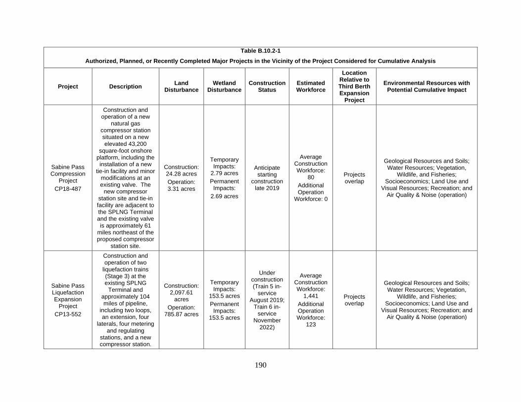
190
Table B.10.2-1
Authorized, Planned, or Recently Completed Major Projects in the Vicinity of the Project Considered for Cumulative Analysis
Project Description Land
Disturbance Wetland
Disturbance Construction
Status Estimated Workforce
Location Relative to Third Berth Expansion
Project
Environmental Resources with Potential Cumulative Impact
Sabine Pass Compression
Project
CP18-487
Construction and operation of a new
natural gas compressor station situated on a new elevated 43,200
square-foot onshore platform, including the installation of a new
tie-in facility and minor modifications at an existing valve. The
new compressor station site and tie-in facility are adjacent to the SPLNG Terminal and the existing valve is approximately 61
miles northeast of the proposed compressor
station site.
Construction: 24.28 acres
Operation: 3.31 acres
Temporary Impacts:
2.79 acres
Permanent Impacts:
2.69 acres
Anticipate starting
construction late 2019
Average Construction Workforce:
80
Additional Operation
Workforce: 0
Projects overlap
Geological Resources and Soils; Water Resources; Vegetation,
Wildlife, and Fisheries; Socioeconomics; Land Use and
Visual Resources; Recreation; and Air Quality & Noise (operation)
Sabine Pass Liquefaction Expansion
Project
CP13-552
Construction and operation of two
liquefaction trains (Stage 3) at the existing SPLNG
Terminal and approximately 104 miles of pipeline,
including two loops, an extension, four
laterals, four metering and regulating
stations, and a new compressor station.
Construction: 2,097.61
acres
Operation: 785.87 acres
Temporary Impacts:
153.5 acres
Permanent Impacts:
153.5 acres
Under construction (Train 5 in-
service August 2019;
Train 6 in-service
November 2022)
Average Construction Workforce:
1,441
Additional Operation Workforce:
123
Projects overlap
Geological Resources and Soils; Water Resources; Vegetation,
Wildlife, and Fisheries; Socioeconomics; Land Use and
Visual Resources; Recreation; and Air Quality & Noise (operation)

191
Table B.10.2-1
Authorized, Planned, or Recently Completed Major Projects in the Vicinity of the Project Considered for Cumulative Analysis
Project Description Land
Disturbance Wetland
Disturbance Construction
Status Estimated Workforce
Location Relative to Third Berth Expansion
Project
Environmental Resources with Potential Cumulative Impact
Gulf Trace Expansion
Project
CP15-29
Installation of an 8-mile 36-inch-diameter lateral and two new
compressor stations.
Construction: 263.43 acres
Operation: 75.60 acres
Temporary Impacts:
121.5 acres
Permanent Impacts:
9.86 acres
In-service (2017)
Average Construction Workforce:
347
Additional Operational Workforce: 0
Projects overlap
Geological Resources and Soils; Water Resources; Vegetation,
Wildlife, and Fisheries; Socioeconomics; Land Use and
Visual Resources; Recreation; and Air Quality & Noise (operation)

192
Table B.10.2-1
Authorized, Planned, or Recently Completed Major Projects in the Vicinity of the Project Considered for Cumulative Analysis
Project Description Land
Disturbance Wetland
Disturbance Construction
Status Estimated Workforce
Location Relative to Third Berth Expansion
Project
Environmental Resources with Potential Cumulative Impact
Calcasieu Pass LNG/
TransCameron Pipeline
CP15-550/CP15-551
Construction and operation of a new
LNG export facility at the juncture of Calcasieu Ship
Channel and Gulf of Mexico, including two 200,000-m3 storage tanks and a marine
berth with two loading docks. In addition, the project will include 24
miles of 42-inch-diameter pipeline.
930 acres
Temporary Impacts:
345.1
Permanent Impacts:
431.3 acres
Under construction
In-service (December
2019)
Average Construction Workforce:
1,575
Additional Operational Workforce:
130
32 miles east of SPLNG Terminal
Air Quality (operation)
Port Arthur Liquefaction
Project
CP17-20
Construction and operation of a new
LNG and export facility on Sabine-
Neches Ship Channel, including feed gas
pre-treatment facilities, two 4.5 MTPA capacity
liquefaction trains, two 160,000-m3 LNG
storage tanks, condensate product
storage, and combustion turbine
generators for captive electricity generation.
Construction: 7,140 acres
Operation: 6,995.40
acres
Temporary Impacts: 1,661.90
acres
Permanent Impacts:
724.0 acres
Anticipate starting
construction in 2019
Average Construction Workforce:
1,300
Additional Operational Workforce:
200
8 miles north of SPLNG Terminal
Water Resources; Vegetation, Wildlife, and Fisheries;
Socioeconomics; Recreation; Air Quality (operation)

193
Table B.10.2-1
Authorized, Planned, or Recently Completed Major Projects in the Vicinity of the Project Considered for Cumulative Analysis
Project Description Land
Disturbance Wetland
Disturbance Construction
Status Estimated Workforce
Location Relative to Third Berth Expansion
Project
Environmental Resources with Potential Cumulative Impact
Texas Connector
Project
CP18-7
Construction and operation of 34.2
miles of new 42-inch-diameter diameter
natural gas pipeline, two compressor
stations, six lateral pipelines, six meter
stations, and associated facilities.
Construction: 664.70 acres
Operation: 186.10 acres
Temporary Impacts:
238.10 acres
Permanent Impacts:
66.8 acres
Anticipate starting
construction in 2019
Average Construction Workforce:
623
Additional Operational Workforce:
20
Projects overlap
Geological Resources and Soils; Water Resources; Vegetation,
Wildlife, and Fisheries; Socioeconomics; Land Use and
Visual Resources; Recreation; and Noise (construction)
Louisiana Connector
Project
CP18-7-000
Construction and operation of 130.8
miles of new 42-inch-diameter natural gas
pipeline, a compressor station, 7 lateral
pipelines, 17 tie-in pipelines, 9 meter
stations, and associated facilities.
Construction: 2,807 acres
Operation:
771 acres
Temporary Impacts:
636.90 acres
Permanent Impacts:
244.10 acres
Anticipate starting
construction in 2019
Average Construction Workforce:
474
Additional Operational Workforce:
10
4 miles northwest of
SPLNG Terminal
Water Resources; Vegetation, Wildlife, and Fisheries;
Socioeconomics
Commonwealth LNG
PF17-8
Construction and operation of eight single liquefaction
trains with capacity of 9 MTPA, a single
berth marine facility, six 40,000-m3 capacity storage tanks, and a
4-mile 30-inch-diameter pipeline.
Construction: 159.6 acres
Operation: 136.5 acres
88 acres
Construction: 1st quarter
2022
Proposed In-service 2nd
quarter 2024
Average Construction Workforce:
800
Additional Operational Workforce:
50-60
31 miles east of SPLNG Terminal
Air Quality (operation)

194
Table B.10.2-1
Authorized, Planned, or Recently Completed Major Projects in the Vicinity of the Project Considered for Cumulative Analysis
Project Description Land
Disturbance Wetland
Disturbance Construction
Status Estimated Workforce
Location Relative to Third Berth Expansion
Project
Environmental Resources with Potential Cumulative Impact
Golden Pass Products
CP14-517
Construction and operation of three
liquefaction process trains, each with a
nominal throughput of 5.2 million MTPA,
associated treatment, power and utility
systems, and interconnections to
existing import facilities and controls.
Construction: 1,017 acres
Operation: 838 acres
Temporary Impacts:
400.8 acres
Permanent Impacts:
385.8 acres
Approved – not under
construction
Proposed In-service (2022)
Average Construction Workforce:
1,888
Additional Operational Workforce:
200
3 miles northwest of
SPLNG Terminal
Water Resources; Vegetation, Wildlife, and Fisheries;
Socioeconomics; Recreation, Air Quality (operation)
Texas DOT
SWG-2012-00680
Discharge of an estimated total of 891 y3 of fill material below
the mean high tide (MHT) line of the Port
Arthur Ship Canal during installation of extended culverts,
bedding, riprap, and sheet pile as bank stabilization and
erosion prevention along a 3.1-mile
distance of SH 87.
Approximately 20 acres
Greater than 3 acres
Construction has not yet
commenced.
TBD – currently
unavailable to public
6.5 miles northwest of
SPLNG Terminal
Water Resources; Vegetation, Wildlife, and Fisheries; and
Socioeconomics.
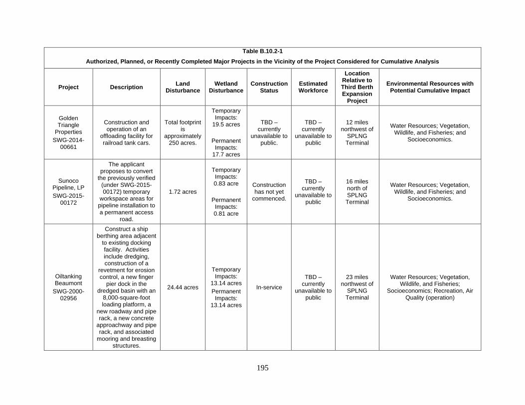
195
Table B.10.2-1
Authorized, Planned, or Recently Completed Major Projects in the Vicinity of the Project Considered for Cumulative Analysis
Project Description Land
Disturbance Wetland
Disturbance Construction
Status Estimated Workforce
Location Relative to Third Berth Expansion
Project
Environmental Resources with Potential Cumulative Impact
Golden Triangle
Properties
SWG-2014-00661
Construction and operation of an
offloading facility for railroad tank cars.
Total footprint is
approximately 250 acres.
Temporary Impacts:
19.5 acres
Permanent Impacts:
17.7 acres
TBD – currently
unavailable to public.
TBD – currently
unavailable to public
12 miles northwest of
SPLNG Terminal
Water Resources; Vegetation, Wildlife, and Fisheries; and
Socioeconomics.
Sunoco Pipeline, LP
SWG-2015-00172
The applicant proposes to convert
the previously verified (under SWG-2015-00172) temporary
workspace areas for pipeline installation to a permanent access
road.
1.72 acres
Temporary Impacts: 0.83 acre
Permanent Impacts: 0.81 acre
Construction has not yet
commenced.
TBD – currently
unavailable to public
16 miles north of SPLNG Terminal
Water Resources; Vegetation, Wildlife, and Fisheries; and
Socioeconomics.
Oiltanking Beaumont
SWG-2000-02956
Construct a ship berthing area adjacent
to existing docking facility. Activities include dredging, construction of a
revetment for erosion control, a new finger
pier dock in the dredged basin with an
8,000-square-foot loading platform, a
new roadway and pipe rack, a new concrete
approachway and pipe rack, and associated
mooring and breasting structures.
24.44 acres
Temporary Impacts:
13.14 acres
Permanent Impacts:
13.14 acres
In-service
TBD – currently
unavailable to public
23 miles northwest of
SPLNG Terminal
Water Resources; Vegetation, Wildlife, and Fisheries;
Socioeconomics; Recreation, Air Quality (operation)

196
Table B.10.2-1
Authorized, Planned, or Recently Completed Major Projects in the Vicinity of the Project Considered for Cumulative Analysis
Project Description Land
Disturbance Wetland
Disturbance Construction
Status Estimated Workforce
Location Relative to Third Berth Expansion
Project
Environmental Resources with Potential Cumulative Impact
USA Rail Terminals, LLC
SWG-2017-00078
Construction of a railroad spur and side rails that will connect
to an existing railroad. The newly constructed facilities will include 21
rail siding lines, varying from 2,580 to 3,507 feet in length,
and a 1.03-mile emergency vehicle access road at the
project site.
56.8 acres
Temporary Impacts:
1.25 acres
Permanent Impacts:
1.25 acres
Construction has not yet commenced
TBD – currently
unavailable to public
23 miles northwest of
SPLNG Terminal
Water Resources; Vegetation, Wildlife, and Fisheries;
Socioeconomics; Air Quality (operation)

197
Table B.10.2-1
Authorized, Planned, or Recently Completed Major Projects in the Vicinity of the Project Considered for Cumulative Analysis
Project Description Land
Disturbance Wetland
Disturbance Construction
Status Estimated Workforce
Location Relative to Third Berth Expansion
Project
Environmental Resources with Potential Cumulative Impact
Martin Midstream
Partners, LP
SWG-2015-00020
The applicant proposes to expand an existing chemical
storage facility. Activities include
installing a new ship dock with breasting dolphins, mooring
dolphins, dock platform, and dock
access trestle, riprap along shoreline for
bank stabilization, and dredging.
TBD – currently
unavailable to public
TBD – currently
unavailable to public
TBD – currently
unavailable to public
TBD – currently
unavailable to public
26 miles northwest of
SPLNG Terminal
Water Resources; Vegetation, Wildlife, and Fisheries;
Socioeconomics; Recreation, Air Quality (operation)
City of Beaumont
SWG-2012-01006
The applicant proposes to retain
27,100 y3 of fill material that was discharged into
Lawson’s Canal, to create an equipment
staging area in preparation for
hurricane or other disaster response.
1.377 acres No Wetland
Impacts
TBD – currently
unavailable to public
TBD – currently
unavailable to public
30 miles northwest of
SPLNG Terminal
Water Resources; Vegetation, Wildlife, and Fisheries;
Socioeconomics; Air Quality (operation)
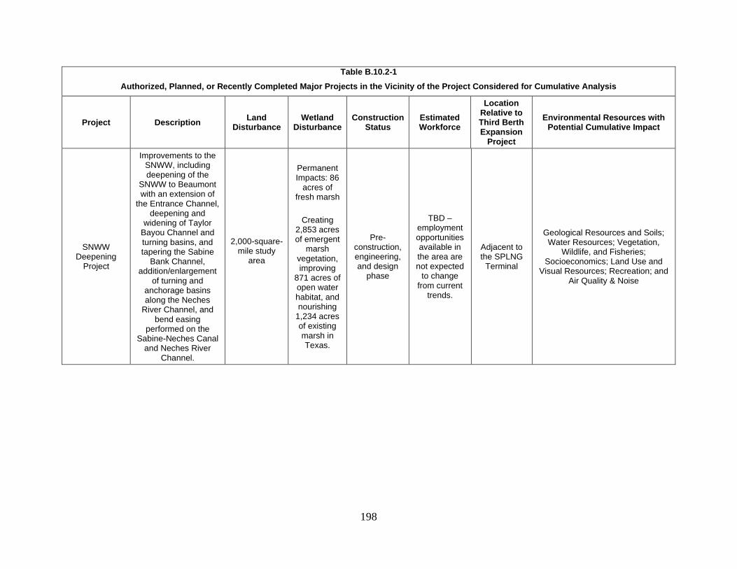
198
Table B.10.2-1
Authorized, Planned, or Recently Completed Major Projects in the Vicinity of the Project Considered for Cumulative Analysis
Project Description Land
Disturbance Wetland
Disturbance Construction
Status Estimated Workforce
Location Relative to Third Berth Expansion
Project
Environmental Resources with Potential Cumulative Impact
SNWW Deepening
Project
Improvements to the SNWW, including deepening of the
SNWW to Beaumont with an extension of
the Entrance Channel, deepening and
widening of Taylor Bayou Channel and turning basins, and tapering the Sabine
Bank Channel, addition/enlargement
of turning and anchorage basins along the Neches
River Channel, and bend easing
performed on the Sabine-Neches Canal
and Neches River Channel.
2,000-square-mile study
area
Permanent Impacts: 86
acres of fresh marsh
Creating 2,853 acres of emergent
marsh vegetation, improving
871 acres of open water habitat, and nourishing
1,234 acres of existing marsh in Texas.
Pre-construction, engineering, and design
phase
TBD – employment opportunities available in the area are not expected
to change from current
trends.
Adjacent to the SPLNG
Terminal
Geological Resources and Soils; Water Resources; Vegetation,
Wildlife, and Fisheries; Socioeconomics; Land Use and
Visual Resources; Recreation; and Air Quality & Noise

199
Figure B.10.2-1 Projects Evaluated for Cumulative Impact Analysis

200
10.3 Analysis of Cumulative Impacts
10.3.1 Geological Resources and Soils
The geographic scope for cumulative impacts on geological resources and soils was
considered to be the area overlapping and adjacent to the Project workspaces. Other projects
within the geographic scope for geological resources and soils that are included in the cumulative
impacts analysis are identified in table B.10.2-1. In addition to overlapping and adjacent
workspaces, projects must be constructed within the same or nearly the same timeframe in order
to contribute towards a cumulative impact on geological resources and/or soils.
Construction of the Third Berth Project would result in permanent changes to the
topographic contours at the site. Similarly, the Sabine Neches Waterway (SNWW) Deeping
Project, located adjacent to the SPLNG Terminal, would also permanently alter topographic
contours through dredging activities. The remaining projects within the geographic scope for
cumulative impacts on geologic resources would likely result in minor alterations of the
topographic contours within and adjacent to the SPLNG Terminal. The natural topography in
the vicinity has been altered during previous activities. Therefore, the construction and operation
of the Project, when combined with other projects in the geographic scope, would not result in
significant cumulative impacts on geologic resources.
The majority of the Project area consists of existing, permanently graveled areas; impacts
on native soils would be limited to the non-graveled portions of the Third Berth (see
section B.2.0). Through implementation of best management practices outlined in the FERC
Plan and Procedures, including use of erosion control devices, SPLNG would minimize the
potential for soil impacts to extend beyond the Project area. Cumulative impacts on soils may
occur when adjacent projects increase the area of soil disturbance resulting in greater potential
for the adverse impacts, or when projects disturb the same area in succession. In the latter
circumstance, soil disturbance may be prolonged and revegetation delayed such that soils are not
sufficiently stabilized, resulting in increased potential for runoff and erosion. In addition, the
prolonged exposure of soils can provide additional opportunity for the establishment of invasive
plant species.
The Third Berth would be constructed within and/or adjacent to workspaces for the
Sabine Pass Liquefaction Project, Sabine Pass Liquefaction Project Modification, Sabine Pass
Expansion Project, Sabine Pass Compression Project, Sabine Pass Liquefaction Expansion
Project, Gulf Trace Expansion Project, and Texas Connector Project (associated with the Port
Arthur LNG Project). The Sabine Pass Liquefaction Project, Sabine Pass Liquefaction Project
Modification, Sabine Pass Expansion Project, and Gulf Trace Expansion Project are all in-
service and it is anticipated that restoration and stabilization of soils would be completed prior to
construction of the Third Berth. In addition, no new permanent impacts would be associated
with the other Sabine Pass Liquefaction projects as land for these projects would already be
converted from soil to gravel or pavement and previously disturbed, and cumulative impacts
resulting from these projects are not anticipated. Construction of the Sabine Pass Compression
Project and the Texas Connector Project would be adjacent to and concurrent with the

201
construction of the Project; therefore, cumulative impacts on soils would occur as a result of the
continued use of these areas during construction of these projects.
The other projects considered for cumulative impacts on soils are also regulated by FERC
and would implement erosion controls similar to those that would be used by SPLNG. Through
the implementation of SPLNG’s proposed mitigation measures, impacts on geological resources
and soils from the Project would be permanent but not significant, contributing to minor
cumulative impacts.
10.3.2 Water Resources
Groundwater Resources
The geographic scope for cumulative impacts on groundwater resources was considered
to be the HUC 8 watershed affected by the Project. Other projects within the geographic scope
for groundwater resources that are included in the cumulative impacts analysis are identified in
table B.10.2-1.
Cumulative impacts on groundwater may occur through construction activities, including
clearing and grading; dewatering; contamination through fuel and other hazardous material
spills; and groundwater withdrawal. As discussed in section B.3.1, the majority of potential
impacts on groundwater resources associated with the Project would be temporary, with
groundwater effects limited to water table elevations in the immediate vicinity of the Project.
The majority of the other projects considered for cumulative impacts on groundwater would
involve ground disturbing activities that could temporarily affect groundwater levels. The
Project could contribute to cumulative impacts on groundwater use, but the minor volume of
water proposed per day during operations would not result in a significant impact on
groundwater resources (see section B.3.1).
Shallow groundwater could be vulnerable to contamination from inadvertent surface
spills of hazardous materials and petroleum products (e.g. fuels, lubricants, and coolants) used
during construction and operation of the Project and other projects within the HUC 8 watershed.
However, SPLNG would implement its Plan and Procedures, as well as its Project-specific
SPCC Plan during construction and SPC-SPCC Plan during operation to minimize the risk of
spills and mitigate potential impacts. Therefore, the potential impacts on groundwater as a result
of contamination, if any, are anticipated to be temporary, localized, and minor. Other projects
considered are anticipated to implement similar measures to prevent spills of hazardous materials
and petroleum products from contaminating groundwater; therefore, we have determined that
cumulative impacts on groundwater quality would be minor.
Surface Water Resources
The geographic scope for surface water resources was considered to be the HUC 8
watershed. Several of the projects listed in table B.10.2-1 could be under construction at the
same time as the Project, and there is potential for cumulative impacts on water quality within
the HUC 8 watershed.

202
Construction of the Project would impact surface water resources as a result of dredging,
stormwater runoff, increased vessel traffic, and increased potential for fuel spills. Other projects
considered for cumulative impacts would have similar impacts on surface waterbodies.
In addition to the Project, other projects on the SNWW (e.g., Sabine Pass Liquefaction
Project, Port Arthur LNG, Oiltanking Beaumont, Martin Midstream Partners, LP, SNWW
Deepening Project) that would require dredging within the HUC 8 watershed would contribute to
a minor cumulative impact of elevated turbidity levels at the Project site and within the SNWW,
which will be determined in part by sediment characteristics at each dredge location. Increased
turbidity from the Project’s dredging operations, combined with concurrent dredging operations
from other projects listed in Table B.10.2-1, within the SNWW, would result in a temporary
cumulative impact on water quality. Clean, coarse sands settle quickly and generate relatively
low turbidity. In contrast, loose silts are easily suspended and do not settle quickly, creating
higher turbidity levels around the dredge. Bottom sediments in the Sabine Pass Channel are fine,
consisting of sand, silt, and clay materials (COE, 2006). The water column is turbid, due to the
high sediment load of inflowing waters and disturbance of bottom sediments by wind action and
vessel traffic. Modeling produced for the dredging operations at the Third Berth shows that after
the dredging operations stop, the concentrations return to background levels within 24 hours
inside the slip and at the channel. In addition, SPLNG would be required to implement the
measures incorporated into the COE permit, including any special requirements or procedures
that may further minimize impacts on water quality as a result of dredging. It is anticipated that
proponents of the other projects on the SNWW listed above would be required to implement
similar measures as a result of their respective COE permits. Due to the temporary and primarily
localized impacts, dredging activities from the Project when combined with the other projects are
not likely to result in significant cumulative impacts.
The concurrent construction of other projects involving clearing, grading, or other
earthwork may also increase the potential for cumulative impacts on water quality from
increased stormwater runoff. All project proponents would be required to adhere to state and
federal regulations regarding hydrostatic, construction, and industrial stormwater and wastewater
discharges. By SPLNG and other project proponents enforcing compliance with these
regulations, and with the implementation of best management practices, including SPLNG’s
ESMP and Project-specific SPCC Plan, and our Procedures, potential cumulative impacts on
surface water resources from stormwater runoff and wastewater discharges would be minimized.
Similarly, it can be reasonably assumed that all projects considered in the cumulative impacts
analysis for surface water resources would be utilizing equipment and or materials that could be
hazardous to the environment in the event of a spill. However, it is anticipated that all of these
projects would prepare and implement a SPCC Plan or similar plan to prevent spills of hazardous
materials from reaching surface water resources, as well as the measures to be implemented if
such a spill occurs. Therefore, cumulative impacts on surface water resources from stormwater
runoff and spills resulting from the construction of the Project and other projects in the HUC 8
watershed are anticipated to be short-term and minor.
203
The Project’s proposed increase of 180 LNGCs annually, would result in impacts on
surface water quality within the Sabine Pass Channel from ballast water discharge, cooling water
discharge, and increased potential for fuel spills. With the exception of the Liquefaction Projects
at the SPLNG Terminal involving expansions of LNG facilities or construction of new LNG
export facilities, the Port Arthur Liquefaction Project, Golden Pass Products Project, and the
SNWW Deepening Project, none of the other projects considered for cumulative impacts on
surface water quality (see table B.10.2-1) are anticipated to result in increased vessel traffic or
direct impacts on the Sabine Pass Channel. It is anticipated that other vessels using the Sabine
Pass Channel would conduct cooling water and ballast water exchanges when moored at their
various destinations. Cooling water exchanges would result in minor changes in water
temperature at the point of discharge, but these impacts are not anticipated to extend beyond the
immediate area (e.g., the Third Berth for the proposed Project), with temperatures quickly
returning to ambient temperatures. The Coast Guard requires that all vessels carry out an open-
ocean ballast water exchange prior to calling at U.S. ports. Ballast water can affect water quality
by discharging water that differs in the physiochemical properties of the ambient water,
including pH, salinity, and temperature. Similar to cooling water, impacts on water quality from
ballast water exchange are anticipated to be localized. Increased vessel traffic could also
increase the potential for spills. All vessels are required to maintain a SOPEP on board to
minimize impacts from a potential spill. Therefore, cumulative impacts on water quality as a
result of increased vessel traffic are not anticipated to be significant.
In addition, the Project would impact surface water resources during operation through
the discharge of industrial wastewater and stormwater. As discussed above, SPLNG and other
project proponents requiring the discharge of stormwater and wastewater would be required to
adhere to federal and state regulations to minimize impacts on surface water resources.
Therefore, cumulative impacts on water quality as a result of operation of the Project are not
anticipated to be significant.
Wetlands
The geographic scope for cumulative impacts on wetlands was determined to be the
HUC 8 watershed. Wetlands provide important ecosystem functions due to their ability to retain
water, minimizing flooding and improving water quality by filtering contaminants before
reaching surface waterbodies. Therefore, conversion of wetlands to uplands or developed land
can affect water quality, as well as flooding, within a watershed. Wetlands also provide valuable
wildlife habitat.
The COE issues permits under Section 404 of the CWA for construction in jurisdictional
Waters of the U.S., including wetlands, and requires mitigation or compensation to ensure there
is no net loss of wetlands or wetland functions. If approved and constructed, the Project,
combined with these other projects identified in table B.10.2-1, could result in a cumulative
impact on the quantity, function, quality, and/or types of wetlands within the HUC 8 watershed.
Other projects within the HUC 8 watershed that were constructed within the past three years
(and/or will be constructed concurrently with or up to three years beyond completion of the
Project) could contribute to a cumulative impact on wetlands in the same watershed as the

204
Project. The Project and other projects in the surrounding area would impact emergent and shrub
scrub wetlands and these types of wetlands were assumed to have an approximate three-year
revegetation time. Forested wetlands would have a longer regeneration time, but no forested
wetlands are impacted by the Project.
Temporary impacts associated with construction include the potential for runoff from
construction areas that could temporarily increase turbidity and sedimentation in adjacent
wetlands. Several of the projects identified propose fill or modifications to wetlands, resulting in
permanent loss or conversion to other habitat types. These impacts would be offset by
compensatory mitigation either through the purchase of credits from established mitigation banks
or in lieu mitigation. For those projects under the jurisdiction of FERC, project proponents will
be required to comply with the FERC Procedures to minimize impact on wetlands. For those
projects solely under the jurisdiction of the COE, the COE would require that best management
practices be implemented. Therefore, cumulative impacts associated with construction of the
Project and other projects within the HUC 8 watershed would be mitigated to the extent possible.
Table B.10.3-1 below quantifies impacts on wetlands for the other projects within the HUC 8
watershed.
Table B.10.3-1
Wetland Impacts for Other Projects Occurring within same Temporal and Geographic Scope for Water
Resources as the SPLNG Third Berth Expansion Project
Project Temporary Wetland Impacts
(acres) Permanent Wetland Impacts
(acres)
Sabine Pass Liquefaction Project 136.28 136.28
Sabine Pass Liquefaction Project Modification
153.53 153.53
Sabine Pass Expansion Project 0.0 0.0
Sabine Pass Compression Project 2.79 2.69
Sabine Pass Liquefaction Expansion Project (Stage 3)
153.5 153.5
Gulf Trace Expansion Project 121.5 9.86
Port Arthur Liquefaction Project/Texas Connector Project/Louisiana Connector
Project 758.3 725.7
Golden Pass Products 400.8 385.8
Texas DOT >3.0 >3.0
Golden Triangle Properties 19.5 17.7
Sunoco Pipeline, LP 0.83 0.81
Oiltanking Beaumont 13.14 13.14

205
Table B.10.3-1
Wetland Impacts for Other Projects Occurring within same Temporal and Geographic Scope for Water
Resources as the SPLNG Third Berth Expansion Project
Project Temporary Wetland Impacts
(acres) Permanent Wetland Impacts
(acres)
USA Rail Terminals, LLC 1.25 1.25
Martin Midstream Partners, LP Unknown Unknown
City of Beaumont 0.0 0.0
SNWW Deepening Project 86 86
Totals 1,850.42 1,689.26
The SNWW project would result in beneficial impacts from the creation and
improvement of wetland habitats. Approximately 748,000,000 y3 of material would be dredged
from the channel and placed in various beneficial use sites within the HUC 8 watershed. The
proposed Neches River and Gulf Shore beneficial use features would create 2,853 acres of
emergent marsh vegetation, improve 871 acres of open water habitat, and nourish 1,234 acres of
existing marsh in Texas. Beneficial use would have a positive cumulative impact to wetland
habitats within the watershed and would help to offset the permanent impacts to wetlands from
the Project and the other projects identified in table B.10.2-1. All projects and activities listed in
table B.10.2-1 that would impact jurisdictional wetlands would be required to comply with the
CWA by avoiding, minimizing, or mitigating wetland impacts. Due to the requirement of the
proposed Project and other projects considered for cumulative impacts to mitigate for wetland
loss, we conclude that cumulative impacts on wetlands would not be significant.
10.3.3 Vegetation, Wildlife, and Aquatic Resources
The geographic scope for cumulative impacts on vegetation, wildlife, and threatened and
endangered species was considered to be the HUC 8 watershed. Other projects located within
the geographic scope for vegetation, wildlife, and fisheries that are included in the cumulative
impacts analysis are identified in table B.10.2-1.
Vegetation and Wildlife
Vegetation plays an important role in an ecosystem, providing wildlife habitat, stabilizing
soils, assisting in drainage, and providing filtration of stormwater within the watershed.
Removal of vegetation can lead to loss or degradation of wildlife habitat, increased stormwater
runoff, decreased water quality, increased erosion, and increased flooding.
Concurrent construction and operation of the Project with other projects included in
table B.10.2-1, would result in temporary and permanent conversion of vegetated areas to
unvegetated industrial land. The vegetation communities that would be affected by the Project
would primarily be wetland and marsh habitat.

206
Increased development and loss of habitat within the geographic scope would cause
wildlife to either adapt to new conditions (in the case of generalist species) or relocate to
undisturbed suitable habitat. Displacement of wildlife could result in additional stress and
increased competition in available habitats. In addition, direct mortality of less mobile species
may occur as a result of development activities. Concurrent construction and operation of the
Project with other projects included in table B.10.2-1, would result in temporary and permanent
disturbance of habitat, increased noise and lighting, and increased traffic that could disturb
wildlife in the area.
A majority of the projects listed in table B.10.2-1 have potential to contribute towards a
cumulative impact on vegetation and wildlife when combined with the impacts from the Project.
These projects, if constructed in the same general location and timeframe, could have a
cumulative impact on local vegetation communities but would not have a significant impact on
regional vegetation.
Construction and operation of the Project and other industrial facilities would result in
permanent impacts on wildlife from habitat loss and increased noise and lighting. Dredging for
the Project and other projects considered would result in the conversion of terrestrial wildlife
habitat to open water habitat. Dredged material from the Project would be disposed at a selected
mitigation site and approved DMPA location (see section A.8.2.1). The placement of dredged
material at these sites will provide shoreline protection and additional wildlife habitat. The
Project would be constructed within and adjacent to an existing industrial site that likely provides
poor quality habitat for wildlife. In addition, the overall acreage of affected habitat of projects
considered for cumulative impacts on wildlife (see table B.10.2-1) is relatively small compared
to the total available habitat in the geographic scope. Therefore, we conclude that cumulative
impacts on wildlife are not significant and that the Project when considered with the other
projects in the HUC 8 watershed would not contribute to significant cumulative impacts on
wildlife resources.
Aquatic Resources
Impacts on aquatic resources as a result of the Project would primarily be limited
dredging and pile driving during construction and the increase of 180 LNGCs calling on the
SPLNG terminal annually. While pile driving during construction of the Project would impact
aquatic resources (see section B.4.2.2), it is not anticipated that other projects in the area would
require pile driving. During pile driving and dredging associated with the project, it is
anticipated that fish and other mobile aquatic resources would relocate to nearby suitable habitat.
If dredging or other in-water activities associated with the other projects considered, occur
concurrent with the proposed Project activities, available undisturbed habitat in the Project
vicinity could be limited; thereby increasing density and competition in adjacent habitats. Due to
the generally localized and temporary impact on water quality that could affect aquatic resources
associated with dredging, as discussed above for cumulative impacts on surface water,
cumulative impacts on aquatic resources during construction are not anticipated to be significant.

207
The increase of 180 LNGCs annually associated with operation of the Third Berth
Facilities would impact aquatic resources by increasing the potential for vessel strikes by
transiting LNGCs in the Gulf of Mexico and the Sabine Pass Channel, impingement and
entrainment of aquatic resources during cooling water intake, and alteration of water quality
during ballast water and cooling water discharges. With the exception of the Liquefaction
Projects at the SPLNG Terminal involving expansions of LNG facilities or construction of new
LNG export facilities, the Port Arthur Liquefaction Project, Golden Pass Products Project, and
the SNWW Deepening Project, none of the other projects considered for cumulative impacts are
known to result in increases in vessel traffic. The SNWW Deepening Project will not directly
add new industrial facilities and shipping berths, but the deepening will indirectly result in
increased shipping traffic and larger vessels entering the waterway. All LNGCs calling on the
SPLNG Terminal as a result of the Project, the Liquefaction Projects, and the SNWW Deepening
Project would transit existing vessel transit routes and would implement the NMFS Vessel Strike
Avoidance Measures and Reporting for Mariners (2008) to minimize the potential for vessel
strikes. The operation of an additional 180 LNGCs within the existing marine berth at the
SPLNG terminal would result in more frequent ballast water and cooling water discharges, and
cooling water intakes. These impacts are anticipated to be limited to the marine berth (see
section B.4.2.2), and therefore, cumulative impacts on aquatic resources as a result of the Third
Berth Facilities are not anticipated to be significant.
Threatened and Endangered Species
The Project, and all projects listed in table B.10.2-1 would be required to comply with the
ESA and all projects requiring federal permits would be required to adhere to Section 7 of the
ESA. As part of the Section 7 consultation process, the FWS and NMFS would review each
project’s potential impacts on federally listed species. Because the Project would have no effect
on or be not likely to adversely affect threatened, endangered, and other special status species
and because the other projects would also be required to comply with the ESA, we conclude that
the Project, when considered with the other projects in the HUC 8 watershed, would not
contribute to significant cumulative impacts on threatened, endangered, and other special status
species.
10.3.4 Socioeconomics
The geographic scope for the assessment of cumulative impacts for the Project on
socioeconomic resources includes Cameron Parish, Louisiana and Jefferson County, Texas
where the majority of the Project workforce is anticipated to reside. While many of the projects
listed in table B.10.2-1 have the potential to contribute to cumulative impacts on socioeconomic
resources within the geographic scope, these impacts would be greatest during concurrent
construction of projects with large construction workforces, such as the Golden Pass Products
Project. For the purposes of this analysis, the review of cumulative impacts focused on projects
that are anticipated to be constructed concurrently with the Project, when socioeconomic
cumulative impacts would be greatest.

208
SPLNG anticipates that the Project workforce would primarily consist of local
individuals. However, the concurrent construction of other large industrial projects, such as the
Golden Pass Products Project, could limit the availability of local workers. In addition, the
construction and operation workforces required for major industrial projects in Cameron Parish,
Louisiana and Jefferson County, Texas could result in increased demand for housing and public
services such as schools, health care facilities, social services, utilities, and emergency services if
non-local workers relocate to the area with their families. Based on the number of available
rental units and motels/hotels in the Project area, it is anticipated that there would be sufficient
housing available, even if additional non-local workers were needed. Further, if more non-local
construction workers relocate to the area with their families, including school age children, than
are anticipated, this would increase the population in some schools where the non-local workers
reside. However, it is likely that those families would be housed throughout many school
districts in various counties and the increase in school population would be distributed through
many schools. SPLNG and other large industrial projects would work directly with local law
enforcement, fire departments, and emergency medical services to coordinate for effective
emergency response. For the reasons listed, we conclude that cumulative impacts on public
services and housing would be short-term and not significant. Operation workforces would be
much smaller than construction workforces and are not anticipated to result in significant
cumulative impacts.
The Project along with the other projects would contribute to the local, regional, and state
economy in terms of direct payroll expenditures, purchase of supplies and materials, indirect
employment in the service sector, and taxes. With the increase in local taxes and government
revenue associated with the Project as well as the other projects, the overall cumulative impact on
taxes and revenue during construction and operation of the Project is anticipated to be generally
positive.
Where other projects are constructed at the same time as the proposed Project, the
potential for additional traffic congestion exists, particularly where the projects share routes for
workers and/or site deliveries. Construction of the Project would have the greatest impact on
traffic, especially during peak construction. Cumulative impacts on traffic from concurrent
construction of the Golden Pass LNG Project and the Port Arthur LNG Project are not
anticipated, as these projects would be located in Texas and would not use the same primary
roads as the Project. The Louisiana Connector Project would use SPLNG’s Duck Blind Road
and portions of Staging Area 2 to access the project. Similarly, the Sabine Pass Compression
Project would also utilize SH 82 near the SPLNG Terminal. There would be a cumulative
impact on traffic along SH 82 if these projects are constructed concurrently. SPLNG stated that
they are coordinating with both Port Arthur LNG (Louisiana Connector Project) and Natural Gas
Pipeline Company of America LLC (Sabine Pass Compression Project) regarding timing and
schedule for use of area roadways. Due to staggered project schedules, the distance of the
various projects listed in table B.10.2-1 from the Project, and SPLNG’s commitment to
coordinate with other projects in the area, cumulative impacts on traffic are anticipated to be
localized and not significant.

209
Other projects that would result in an increase in vessel traffic within the Sabine Pass
Channel due to expansions of LNG facilities or construction of new LNG export facilities or new
shipping berths include the Sabine Pass Liquefaction Project, Sabine Pass Liquefaction
Modification Project, Sabine Pass Liquefaction Expansion Project, Port Arthur Liquefaction
Project, Golden Pass Products, Oiltanking Beaumont, Martin Midstream Partners, LP, and
SNWW Deepening Project.
The SNWW Deepening Project will not directly add new LNG facilities and shipping
berths, but the deepening will indirectly result in increased shipping traffic and larger vessels
entering the waterway. The anticipated increase in LNGCs resulting from the Golden Pass
Products Project and the Port Arthur LNG terminal projects would collectively add up to 600
additional LNGCs per year (along the SNWW). The shipping traffic study that was completed
for the Project (Lanier, 2018) describes the existing capacity and infrastructure of the SNWW
and states that the current conditions of the Waterway are such that increases in LNGC traffic
(180 per year from the proposed Project plus 600 per year from the two other projects mentioned
above) along with the addition of normal traffic growth over the next 10 years, the existing
infrastructure will be adequate to handle more than 1,200 LNGCs per year by the year 2028.
The number 1,200 is a projection of how many LNGCs may pilot the SNWW by 2028, based on
passible future growth within the region served by the SNWW. The other projects listed above
combined with the additional 180 SPLNG vessels per year from the Project, would result in a
cumulative increase in vessel traffic within the Sabine Pass Channel, and also along international
shipping routes. However, the LOR issued for the Project stated that the Sabine Pass Channel is
considered suitable for the increased LNGC traffic associated with the Project (see
section B.7.4.2). Therefore, we conclude that cumulative impacts on marine traffic would not be
significant.
10.3.5 Land Use and Visual Resources
The geographic scope for land use and visual resources includes a 0.5-mile-radius around
the Project facilities.
Land Use
Construction of the projects would result in temporary and permanent changes to land
use. Land would be cleared and disturbed for installation of the project facilities and land would
be permanently converted from previous use to industrial use for operation of the Project
facilities. Projects with permanent aboveground components (e.g., buildings) and roads would
generally have the greatest impacts on land use. New aboveground facilities proposed as part of
the Project include the new loading platform and LNG transfer lines, breasting and mooring
dolphins, and two new buildings (Jetty Marine Building and Customs/Security Building).
The major change in land use related to the Project would be the conversion of existing
marsh to open water habitat. During construction, best management practices would be
employed as required by federal and state regulatory agencies. Impacts to wetlands and
waterbodies from construction of the projects would also require approval from the COE and

210
state regulatory agencies. Other areas affected by Project construction are within the footprint of
the previously certificated SPLNG Terminal boundaries. The other projects identified in the
same geographic scope (0.5 mile) as the Project site are all within this same previously certified
footprint of SPLNG Terminal and would all have similar industrial proposed land use to the
existing facility and the Project. Therefore, we conclude that cumulative impacts on land use
would not be significant.
Visual Resources
Cumulative impacts on visual resources would be greatest near aboveground facilities.
Clearing of tall vegetation such as trees can also result in impacts on visual resources.
The Project is proposed for construction adjacent to the existing SPLNG Terminal
berthing area, and all new facilities would be located within an industrial area and are consistent
with the surrounding viewshed. Therefore, we conclude that cumulative impacts on visual
resources would be negligible.
10.3.6 Recreation
Other projects, as well as the Project, that result in increased vessel traffic within the
Sabine Pass Channel, would contribute towards a cumulative impact on fishing, boating, or other
recreational activities along the shoreline. Although the Sabine Pass Channel is primarily used
as a major shipping route for large vessels, some recreational fishing and boating still occurs
within the waterway as well as fishing from the shoreline. Therefore, anyone who uses the
Sabine Pass Channel for recreational fishing, would notice an increase in vessel traffic. When
combined with the other projects identified in table B.10.2-1, we conclude the Project would not
result in significant cumulative impacts on recreation.
10.3.7 Air and Noise Quality
Air
Emissions of criteria air pollutants and HAPs (i.e., non-GHG pollutants) from sources in
the vicinity of the Project would be additive. The cumulative impact area for air quality during
the construction phase of the Project is the area adjacent to and near the boundary of the Project
site. More specifically, the geographic scope for construction air emissions was a 0.25-mile
radius around Project facilities. Typically, the geographic scope for operations air emissions is a
50-kilometer radius around project facilities. However, it should be noted that for this Project,
no new emission sources (only increases of emissions from the existing Enclosed Ground Marine
Flare and pipeline fugitives) are being added at the SPLNG Terminal. The primary emissions
increase associated with the Project is from the additional 180 LNGCs that will be calling at the
SPLNG Terminal annually. To get an understanding of the potential cumulative effects from
that additional marine traffic, an analysis conducted for the Port Arthur Liquefaction Project
Environmental Impact Statement (EIS) is referenced. (Note that the Port Arthur Liquefaction
Project is located 8 miles north of the SPLNG Terminal.) That analysis for the Port Arthur

211
Liquefaction Project found that the increase in marine vessel traffic would be less than one
percent of the total marine vessel traffic through Sabine Pass.
Although FERC typically uses 50 km to define the geographic scope around the Project
site for cumulative impacts assessment of criteria pollutants and HAPs, FERC does not use such
a geographic scope to evaluate GHG emissions. GHGs were identified by the EPA as pollutants
in the context of climate change. GHG emissions do not directly cause local ambient air quality
impacts. GHG emissions result in fundamentally global impacts that feedback to localized
climate change impacts. Thus, the geographic scope for cumulative analysis of GHG emissions
is global rather than local or regional. For example, a project 1 mile away emitting 1 ton of
GHGs would contribute to climate change in a similar manner as a project 2,000 miles distant
also emitting 1 ton of GHGs.
Construction of the Project and many of the past, present, or future projects listed in
table B.10.2-1 would involve the use of construction equipment that generates air pollution;
including fugitive dust. Temporary cumulative impacts on local air quality from non-GHG
pollutants would result from overlapping construction schedules and geographies for other
projects with the Project. In general, the emissions from construction activities for the Project
and other projects in the region would result in short-term cumulative emissions that would be
substantially localized to each project area. Operation of construction equipment for the Project
would be primarily restricted to daylight hours and would be minimized through typical controls
and practices, some of which are required under LDEQ rules; therefore, construction emissions
are not expected to have a significant cumulative impact on local or regional air quality.
Operation of the Project, most notably the additional 180 LNG carriers and associated
support vessels in the vicinity of the pier, would contribute cumulatively to non-GHG air
pollutant levels in combination with the existing SPLNG Terminal. As discussed in section
B.8.1, a detailed air quality impact analysis was conducted by SPLNG to quantitatively evaluate
the combined impacts from operation of the Project (including marine vessels) and the existing
SPLNG Terminal emission sources, plus representative pollutant background concentrations.
Those combined impacts were compared against the NAAQS, which are designed to be
protective of human health and welfare, including the environment. The results of the air quality
impact analyses demonstrated that the Project emissions would not cause or contribute to an
exceedance of the NAAQS. Based on this result, we conclude that the Project would not have a
significant cumulative air quality impact within the 50-kilometer radius around the Project
location.
Newly proposed (future) projects in the region would contribute cumulatively to air
quality impacts from non-GHG pollutants through construction and operation activities. Each of
these projects would need to comply with federal, state, and local air quality regulations, which
may require controls to limit the emissions of certain criteria pollutants or HAPs. Although
outside the scope of our analysis, it is anticipated that these project activities would result in
increased permanent emissions of criteria pollutants, HAPs, and GHGs within the region. The
Project's associated operating emissions, which essentially are limited to increases in emissions
from existing sources at the SPLNG Terminal, would be mitigated by compliance with
conditions in federal and state permits and approvals. Thus, Project operations are not

212
anticipated to contribute to the cumulative impact of non-GHG air pollutants on local or regional
air quality.
Climate Change
Climate change is the variation in climate (including temperature, precipitation, humidity,
wind, and other meteorological variables) over time, whether due to natural variability, human
activities, or a combination of both, and cannot be characterized by an individual event or
anomalous weather pattern. For example, a severe drought or abnormally hot summer in a
particular region is not a certain indication of climate change. However, a series of severe
droughts or hot summers that statistically alter the trend in average precipitation or temperature
over decades may indicate climate change. Recent research has begun to attribute certain
extreme weather events to climate change (U.S. scientific body on climate change is the U.S.
Global Change Research Program [USGCRP], 2018).
The leading U.S. scientific body on climate change is the USGCRP, composed of
representatives from thirteen federal departments and agencies.36 The Global Change Research
Act of 1990 requires the USGCRP to submit a report to the President and Congress no less than
every four years that “1) integrates, evaluates, and interprets the findings of the Program; 2)
analyzes the effects of global change on the natural environment, agriculture, energy production
and use, land and water resources, transportation, human health and welfare, human social
systems, and biological diversity; and 3) analyzes current trends in global change, both
human-induced and natural, and projects major trends for the subsequent 25 to 100 years.”
These reports describe the state of the science relating to climate change and the effects of
climate change on different regions of the U.S. and on various societal and environmental
sectors, such as water resources, agriculture, energy use, and human health.
In 2017 and 2018, the USGCRP issued its Climate Science Special Report: Fourth
National Climate Assessment, Volumes I and II (Fourth Assessment Report) (USGCRP, 2017;
and USGCRP, 2018, respectively). The Fourth Assessment Report states that climate change has
resulted in a wide range of impacts across every region of the country. Those impacts extend
beyond atmospheric climate change alone and include changes to water resources, transportation,
agriculture, ecosystems, and human health. The U.S. and the world are warming; global sea
level is rising and acidifying; and certain weather events are becoming more frequent and more
severe. These changes are driven by accumulation of GHG in the atmosphere through
combustion of fossil fuels (coal, petroleum, and natural gas), combined with agriculture, clearing
of forests, and other natural sources. These impacts have accelerated throughout the end of the
20th and into the 21st century (USGCRP 2018).
36 The USGCRP member agencies are: Department of Agriculture, Department of Commerce, Department of
Defense, Department of Energy, Department of Health and Human Services, Department of the Interior,
Department of State, Department of Transportation, Environmental Protection Agency, National Aeronautics and
Space Administration, National Science Foundation, Smithsonian Institution, and U.S. Agency for International
Development.

213
Climate change is a global phenomenon; however, for this analysis, we will focus on the
existing and potential cumulative climate change impacts in the Project area. The USGCRP’s
Fourth Assessment Report notes that the following observations of environmental impacts are
attributed to climate change in the Southern Great Plains and U.S. Gulf Coast regions
(USGCRP, 2017; USGCRP, 2018):
• The region has experienced an increase in annual average temperature of 1-2°F since
the early 20th century, with the greatest warming during the winter months. There
have been increasing number of days above 95 °F and nights above 75 °F, with a
decreasing number of extremely cold days since the 1970s.
• The region has experienced an increase in precipitation. Most notably, fall
precipitation has increased by 40 percent since 1948. The number of heavy
downpours has increased throughout the region.
• The number of strong (Category 4 and 5) Atlantic hurricanes (including the Gulf of
Mexico) has increased since the early 1980s.
• Along the Gulf Coast, sea levels have risen 5-17 inches over the past 100 years
depending on local topography and subsidence.
• Many coastal areas in Texas and Louisiana are subsiding; local land elevation is
sinking relative to sea level. Observed subsidence rates in the southeast are
significant. The highest rise in relative sea level in the U.S. is found in Louisiana (0.3
to 0.4 inch per year) and Texas (0.2 to 0.3 inch per year).
The USGCRP’s Fourth Assessment Report notes the following projections of climate
change impacts in the Project region with a high or very high level of confidence37 (USGCRP,
2018):
• Annual average temperatures in the Southern Great Plains are projected to increase by
3.6°–5.1°F by the mid-21st century and by 4.4°-8.4°F by the late 21st century,
compared to the average for 1976-2005.
• The change in the number of hot days and warm nights is projected to increase
dramatically by mid-century for the Gulf Coast. The region is projected to experience
an additional 30 to 60 days per year above 100 °F than it does currently.
• Tropical storms are projected to be fewer in number globally, but stronger in force,
exacerbating the loss of barrier islands and coastal habitats.
37 The report authors assessed current scientific understanding of climate change based on available scientific
literature. Each “Key Finding” listed in the report is accompanied by a confidence statement indicating the
consistency of evidence or the consistency of model projections. A high level of confidence results from “moderate
evidence (several sources, some consistency, methods vary and/or documentation limited, etc.), medium consensus.”
A very high level of confidence results from “strong evidence (established theory, multiple sources, consistent
results, well documented and accepted methods, etc.), high consensus.”
https://science2017.globalchange.gov/chapter/front-matter-guide/
214
• The region is projected to see longer dry spells, although the number of days with
heavy precipitation is expected to increase by mid-century. Longer periods of time
between rainfall events may lead to declines in recharge of groundwater, which
would likely lead to saltwater intrusion into shallow aquifers and decreased
freshwater availability.
• Sea level rise along the Gulf of Mexico during the remainder of the 21st century is
likely to be greater than the projected global average of 1-4 feet or more, which
would result in the loss of a large portion of remaining coastal wetlands. Combined
with sea level rise, local subsidence will lead to a higher “relative” change in the sea
level at the local scale.
It should be noted that while the impacts described above taken individually may be
manageable for certain communities, the impacts of compound extreme events (such as
simultaneous heat and drought, wildfires associated with hot and dry conditions, or flooding
associated with high precipitation on top of saturated soils) can be greater than the sum of the
parts (USGCRP, 2018).
The GHG emissions associated with construction and operation of the Project are
presented in section B.8.1. Construction and operation of the Project would increase the
atmospheric concentration of GHGs, in combination with past, current, and future emissions
from all other sources globally and contribute incrementally to future climate change impacts.
Currently, there is no universally accepted methodology to attribute discrete, quantifiable,
physical effects on the environment to a project’s incremental contribution to GHGs. We have
looked at atmospheric modeling used by the EPA, National Aeronautics and Space
Administration, the Intergovernmental Panel on Climate Change, and others and we found that
these models are not reasonable for project-level analysis for a number of reasons. For example,
these global models are not suited to determine the incremental impact of individual projects,
due to both scale and overwhelming complexity. We also reviewed simpler models and
mathematical techniques to determine global physical effects caused by GHG emissions, such as
increases in global atmospheric CO2 concentrations, atmospheric forcing, or ocean CO2
absorption. We could not identify a reliable, less complex model for this task and we are not
aware of a tool to meaningfully attribute specific increases in global CO2 concentrations, heat
forcing, or similar global impacts to project-specific GHG emissions. Similarly, it is not
currently possible to determine localized or regional impacts from GHG emissions from the
Project.
Absent such a method for relating GHG emissions to specific resource impacts, we are
not able to assess potential GHG-related impacts attributable to this project. Additionally, we
have not been able to find any GHG emission reduction goals established either at the federal
level38 or by the State of Louisiana. Without either the ability to determine discrete resource
38 The national emissions reduction targets expressed in the EPA’s Clean Power Plan were repealed in June
2019 and the Paris climate accord is pending withdrawal.

215
impacts or an established target to compare GHG emissions against, we are unable to determine
the significance of the Project’s contribution to climate change.
Noise
The geographic scope for cumulative impacts on noise was considered to be a 1 -mile
radius of the Project site. Noise impacts are generally localized and attenuate significantly as the
distance from the sound source increases. Cumulative noise impacts on residences and other
NSAs are related to the distance from the disparate noise sources as well as the timing of each
noise source. For instance, construction activities would not have any cumulative noise impact
unless they are taking place simultaneously. There is the potential for operations noise from
nearby projects to contribute to cumulative sound level impacts at NSAs, depending on the
distance and direction of the projects to each other and the NSAs.
Seven of the other projects identified in the cumulative impacts analysis, as presented in
table B.10.2-1, occur within the geographic scope for noise and include the Texas Connector
Project, Sabine Pass Expansion Project, Sabine Pass Compression Project, Sabine Pass
Liquefaction Project, Sabine Pass Liquefaction Project Modification, Liquefaction Expansion
Project, and SNWW Deepening Project. While the Sabine Pass Liquefaction Project and the
Sabine Pass Liquefaction Project Modification occur within the geographic scope for cumulative
impacts on noise, these projects are currently in operation and the associated sound levels were
included in the ambient measurements recorded during the Project sound level survey; therefore,
the associated cumulative impacts have already been addressed in the analysis in section B.8.2 of
this EA. In addition, the Sabine Pass Expansion Project components located within the
geographic scope considered for noise include a new pipeline lateral and tap, which would not
have any continuous operational noise impact. Further, the new pipeline lateral and tap
associated with the Sabine Pass Expansion Project were placed in-service in August 2019.
Therefore, construction and operation of these Sabine Pass Expansion Project facilities and the
Project would not contribute to cumulative impacts on noise.
Construction of the Texas Connector Project is scheduled to begin in the fourth quarter of
2019 and be placed in-service in the third quarter of 2022, and therefore, would overlap with
construction of the Project. The Texas Connector Project facilities located within the geographic
scope considered for cumulative impacts on noise include a portion of a new natural gas pipeline,
a natural gas pipeline lateral, and a meter station identified as the KMLP Meter Station.
Cumulative noise impacts may occur due to the concurrent construction activities for these Texas
Connector Project facilities and the proposed Project. However, pipeline construction activities
are typically short-term at any given location, and the meter station construction activities would
be temporary; therefore, cumulative construction noise impacts would be temporary. In addition,
the combined operation of the KMLP Meter Station and the Project could result in cumulative
noise impacts. However, based on noise analyses completed for the Texas Connector Project,
operation of the KMLP Meter Station is not expected to have a noticeable impact on the ambient
sound levels at the nearest NSA.

216
The Sabine Pass Liquefaction Expansion (SPLE) Project facilities located within the
geographic scope for cumulative noise impacts consist of the construction and operation of two
additional LNG trains, Trains 5 and 6, at the existing SPLNG Terminal. Construction of Train 6
for the SPLE Project began in November 2018 and is scheduled for completion in
November 2022, which would overlap with Project construction. Therefore, cumulative impacts
on noise may occur due to the concurrent construction of Train 6 for the SPLE Project and the
proposed Project, as well as the combined operation of both Trains 5 and 6 and the Project.
A summary of the cumulative sound level impact resulting from concurrent construction
of the Project and Train 6 for the SPLE Project is presented in table B.10.3-2 below.
Table B.10.3-2
Cumulative Sound Level Impact Evaluation for Construction of the Project and the Sabine Pass Liquefaction
Expansion Project (Train 6)
NSA
Existing Ambient
(dBA Ldn)
Train 6 Construction
Sound Levels
(dBA Leq)
Train 6 Construction
Sound Levels
(dBA Ldn)
Combined Project Day-Night Levels
from Construction, Pile Driving,
and Dredging (dBA Ldn)
Cumulative Project
Construction Levels with
Train 6 Contribution
(dBA Ldn)
Cumulative Project
Construction Levels with Train
6 Contribution and Ambient
(dBA Ldn)
Potential Increase Above
Existing (dB)
1 55.9 40.3 37.3 47.2 47.6 56.5 0.6
2 53.3 41.1 38.1 58.2 58.3 59.5 6.2
3 53.6 40.8 37.8 39.9 41.9 53.8 0.3
As shown in table B.10.3-2, the cumulative construction sound levels at NSA 1 and
NSA 3 would be below 55 Ldn as a result of concurrent construction of the Project and the SPLE
Project. At NSA 2, the cumulative sound level from concurrent construction activities would
exceed 55 Ldn, but based on SPLNG’s cumulative noise impact evaluation, concurrent
construction of both projects would result in an increase of only 0.1 dBA above the sound levels
estimated for construction of the Project at NSA 2.
In addition to construction noise, operation of Trains 5 and 6 for the SPLE Project and
the new Compressor Station 348 for the Sabine Pass Compression Project would result in
cumulative impacts on noise when combined with operation of the Project. Natural Gas Pipeline
Company of America LLC estimated the sound level contribution from operation of the new
Compressor Station 348 at the nearest NSAs, as presented in Resource Report 9 for the Sabine
Pass Compression Project.39 The ambient sound level measurements recorded for the Project
included noise from the operation of Trains 1 through 4 at the SPLNG Terminal and noise
associated with construction of Train 5. The operational noise of Trains 1 through 4 at full load
at the nearby NSAs was measured and reported in the post-construction noise survey for the
project. SPLNG utilized this data to estimate the operational noise from Trains 5 and 6 by using
39 Provided by Natural Gas Pipeline Company of America in Resource Report 9 of their Environmental Report filing
on May 24, 2018, which is available on the FERC eLibrary website at
https://elibrary.ferc.gov/idmws/search/fercadvsearch.asp under accession number 20180524-5038.

217
a distance adjustment and subtracting 3 dB to account for approximately half the number of
noise sources for Trains 5 and 6 compared with Trains 1 through 4. By combining this estimate
for Trains 5 and 6 with the predicted sound levels for operation of the Sabine Pass Compression
Project and the proposed Project, SPLNG estimated the total cumulative sound level impact for
operation of the Project, Compressor Station 348, and Trains 1 through 6 at the SPLNG
Terminal, as presented in table B.10.3-3.
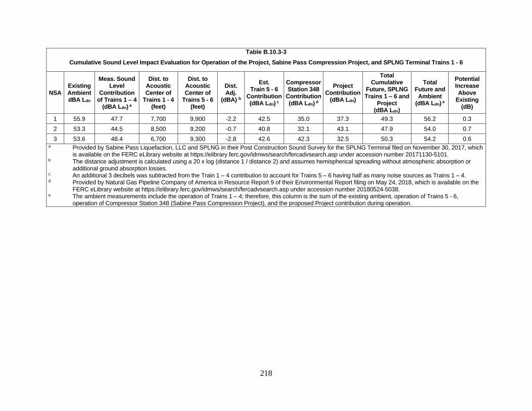
218
Table B.10.3-3
Cumulative Sound Level Impact Evaluation for Operation of the Project, Sabine Pass Compression Project, and SPLNG Terminal Trains 1 - 6
NSA Existing Ambient dBA Ldn
Meas. Sound Level
Contribution of Trains 1 – 4
(dBA Ldn) a
Dist. to Acoustic Center of
Trains 1 - 4 (feet)
Dist. to Acoustic Center of
Trains 5 - 6 (feet)
Dist. Adj.
(dBA) b
Est. Train 5 - 6
Contribution (dBA Ldn)
c
Compressor Station 348
Contribution (dBA Ldn)
d
Project Contribution
(dBA Ldn)
Total Cumulative
Future, SPLNG Trains 1 – 6 and
Project (dBA Ldn)
Total Future and
Ambient (dBA Ldn)
e
Potential Increase Above
Existing (dB)
1 55.9 47.7 7,700 9,900 -2.2 42.5 35.0 37.3 49.3 56.2 0.3
2 53.3 44.5 8,500 9,200 -0.7 40.8 32.1 43.1 47.9 54.0 0.7
3 53.6 48.4 6,700 9,300 -2.8 42.6 42.3 32.5 50.3 54.2 0.6 a Provided by Sabine Pass Liquefaction, LLC and SPLNG in their Post Construction Sound Survey for the SPLNG Terminal filed on November 30, 2017, which
is available on the FERC eLibrary website at https://elibrary.ferc.gov/idmws/search/fercadvsearch.asp under accession number 20171130-5101. b The distance adjustment is calculated using a 20 x log (distance 1 / distance 2) and assumes hemispherical spreading without atmospheric absorption or
additional ground absorption losses. c An additional 3 decibels was subtracted from the Train 1 – 4 contribution to account for Trains 5 – 6 having half as many noise sources as Trains 1 – 4. d Provided by Natural Gas Pipeline Company of America in Resource Report 9 of their Environmental Report filing on May 24, 2018, which is available on the
FERC eLibrary website at https://elibrary.ferc.gov/idmws/search/fercadvsearch.asp under accession number 20180524-5038. e The ambient measurements include the operation of Trains 1 – 4; therefore, this column is the sum of the existing ambient, operation of Trains 5 - 6,
operation of Compressor Station 348 (Sabine Pass Compression Project), and the proposed Project contribution during operation.

219
As presented in table B.10.3-3, the estimated cumulative sound level for operation of the
Project, Compressor Station 348, and Trains 1 through 6 at the SPLNG Terminal is below
55 dBA Ldn at all NSAs, and the noise increases range from 0.3 to 0.7 decibels. This indicates
that the cumulative noise impact from operation of the Project, Compressor Station 348, and the
SPLNG Terminal, including Trains 5 through 6 following completion of the Liquefaction
Expansion Project, is minimal.
Construction of the SNWW Deepening Project is scheduled to overlap with construction
of the Project. However, the SNWW Deepening Project is linear and construction activities
would range across a large area, thus it is unlikely that construction activities would overlap
with the Project in both time and proximity. Although unlikely, the cumulative impact on sound
levels from concurrent construction of the Project and SNWW Project was estimated using
conservative sound level data for the hopper dredges that are expected to be used during
construction of the SNWW Deepening Project. Using these conservative estimates for the
hopper dredges and the maximum construction sound level estimated for Project construction,
the cumulative sound level impact at the closest NSA (NSA 2) to the Project would increase the
estimated daytime and nighttime sound levels by 0.1 dBA and 3 dBA, respectively, above the
sound levels estimated for construction of the Project alone. Therefore, the total cumulative
sound levels estimated for concurrent construction of the Project and the SNWW Deepening
Project at NSA 2 would be 61.2 dBA Leq during the day and 48 dBA Leq at night.
We conclude that the construction noise impact of the projects with potentially
overlapping construction schedules with the Project is largely not additive with other ongoing
construction and would only create a minor cumulative noise impact on the larger region. In
addition, we conclude that the cumulative operational noise impacts from the identified
reasonably foreseeable future actions in the area of the Project are likely to be minor.
SECTION C – ALTERNATIVES
In accordance with NEPA and FERC policy and EPA recommendations, we evaluated a
range of alternatives to determine whether an alternative would be preferable to the proposed
action. The range of alternatives evaluated include the No-Action Alternative, system
alternatives, site alternatives, and design alternatives. Our criteria for determining if an
alternative would be “preferable” are discussed in the following section.
1.0 EVALUATION PROCESS
The purpose of this evaluation is to determine whether an alternative would be preferable
to the proposed action using three evaluation criteria, as discussed in greater detail below. These
criteria include:
• the alternative meets the stated purpose of the project;
• is technically and economically feasible and practical; and
• offers a significant environmental advantage over a proposed action.
The alternatives were reviewed against the evaluation criteria in the sequence presented
above. The first consideration for including an alternative in the analysis is whether or not it

220
could satisfy the stated purpose of the project. An alternative that cannot achieve the purpose for
the project cannot be considered as an acceptable replacement for the project.
For further consideration, an alternative has to be technically and economically feasible.
Technically practical alternatives, with exceptions, would generally require the use of common
construction methods. An alternative that would require the use of a new, unique, or
experimental construction method may not be technically practical because the required
technology is not available or is unproven. Economically practical alternatives would result in
an action that generally maintains the price competitive nature of the proposed action.
Generally, the cost of an alternative as a critical factor is not considered unless the added cost to
design, permit, and construct the alternative would render the project economically impractical.
Determining if an alternative provides a significant environmental advantage requires a
comparison of the impacts on each resource as well as an analysis of impacts on resources that
are not common to the alternatives being considered. The determination must then balance the
overall impacts and all other relevant considerations. In comparing the impact between
resources (factors), the degree of impact anticipated on each resource was also considered.
Ultimately, an alternative that results in equal or minor advantages in terms of environmental
impact would not compel us to shift the impacts from the current set of landowners to a new set
of landowners.
A range of alternatives was considered in light of the Project’s objectives, feasibility, and
environmental consequences. Through environmental comparison and professional judgment,
each alternative is considered to a point where it becomes clear whether the alternative could or
could not meet the three evaluation criteria. To ensure a consistent environmental comparison
and to normalize the comparison factors, desktop sources of information (e.g., publicly available
data, aerial imagery) were generally used and the same general workspace requirements were
assumed. Data collected in the field was evaluated if surveys were completed for both the
proposed site and its corresponding alternative site. Where appropriate, site-specific information
(e.g., detailed designs) was used. Environmental analysis and this evaluation consider
quantitative data (e.g., counts, acreage, or mileage) and use common comparative factors such as
land requirements.
The evaluation also considers impacts on both the natural and human environments. The
natural environment includes water resources and wetlands, vegetation, wildlife and fisheries
habitat, farmland soils, and geology. The human environment includes nearby landowners,
residences, land uses and recreation, utilities, and industrial and commercial development near
construction workspaces. In recognition of the competing interests and the different nature of
impacts resulting from an alternative that sometimes exists (i.e., impacts on the natural
environment versus impacts on the human environment), other factors are considered that are
relevant to a particular alternative or discount or eliminate factors that are not relevant or may
have less weight or significance. In our alternative’s analyses, we often have to weigh impacts
on one kind of resource (i.e., habitat for a species) against another resource (i.e., residential
construction).

221
It is intended that each of the cooperating agencies, as discussed in section A.4.0, will
review this alternatives analysis for consistency with their own administrative procedures, and
those agencies with NEPA obligations may choose to adopt this analysis as part of their
decision-making process.
1.1 No-Action Alternative
Under the no-action alternative SPLNG would not construct the Project. If the Project is
not constructed, then neither the adverse environmental nor beneficial potential economic
impacts described in this EA would occur. Implementing the no-action alternative would not
allow SPLNG to meet the purpose and need as described in section A.2.0.
While the proposed Project would not increase the amount of LNG produced by the
SPLNG Terminal, it would result in increased LNG export through additional LNGCs calling on
the facility. It is reasonable to expect that if the Project is not constructed, other natural gas
export companies would likely construct similar, new facilities to meet the demand for additional
LNG exports. This would likely result in the transfer of environmental impacts from one project
to another or increased impacts (if the new facilities are greenfield projects), but it would not
likely eliminate or reduce impacts.
The no-action alternative would not alleviate demand for LNG in foreign nations, this
alternative would likely result in development of new projects elsewhere, which would lead to
greater environmental impacts due to the need for a new LNG export facility rather than
modifications of an existing facility.
We conclude that the no-action alternative does not meet the Project objective and an
alternative project to meet the market demand would likely not provide a significant
environmental advantage over the proposed action. Therefore, we do not consider it further.
1.2 System Alternatives
System alternatives are those that would meet the stated objectives of the Project but uses
a different (and often existing) facility or a different configuration of facilities that eliminates the
need to construct all or part of the Project. Given the stated objective of the Project, to increase
efficiency and reliability for the loading of LNGCs for transport from the SPLNG Terminal, no
existing or proposed infrastructure was identified that would be a practicable system alternative.
Therefore, we do not consider system alternatives further.
1.3 Site Alternatives
For the purposes of this analysis, site alternatives refer to the siting of the Third Berth at
the existing SPLNG Terminal. As discussed above, the Project would need to be sited at the
SPLNG Terminal to meet the stated Project purpose to increase efficiency and reliability for the
loading of LNGCs for transport from the SPLNG Terminal. Three site locations for the Third
Berth were evaluated based upon proximity to the existing berths, which would minimize the
length of the LNG transfer piping, closeness to existing tug docks, and safety equipment as
222
shown below in figure C.1.3-1. The three site alternatives were compared for environmental
impacts and feasibility (table C.1.3-1). The layout designs utilized in our evaluation of site
alternatives include Sites 1 and 2, and the preferred design layout option for Site 3 (refer to
section C.1.4).
1.3.1 Site 1
Site 1 would be located at the existing construction dock location and would require less
dredging on the shore side when compared to Site 3 (Preferred Site) and would impact less
wetlands. However, a portion of Point Hunt Island, a known bird rookery, would have to be
removed. Additionally, this location would require longer interconnecting transfer piping as
compared to the other two options. Finally, the construction dock is required for the completion
of SPLNG’s train six. Due to the potential dredging of an existing island and impacts on a
known bird rookery, we determined that Site 1 does not provide a significant environmental
advantage to the proposed Project site.

223
Figure C.1.3-1 SPLNG Third Berth Expansion Project Site Alternatives

224
1.3.2 Site 2
Site 2 would be located to the west of the existing berth and would provide a close
connection to the transfer lines and would impact less wetlands. However, Site 2 would also
require a portion of Point Hunt Island to be dredged. In addition, SPLNG does not have a long-
term lease for this area, unlike the other two site locations. Due to the potential dredging of an
existing island and impacts on a known bird rookery, we determined that Site 1 does not provide
a significant environmental advantage to the proposed Project site.
1.3.3 Site 3 (Preferred Site)
Site 3 is east of and adjacent to the existing berth. This alternative would provide a close
connection for tie-ins to the LNG transfer piping and boil-off gas system. While this site would
impact the greatest number of wetlands, it would require the least amount of land, overall.
Further, it would not require dredging of Point Hunt Island or otherwise impact any known bird
rookeries. Therefore, we conclude that Site 3 is the preferred alternative.
Table C.1.3-1
Evaluation of Site Alternatives for the Third Berth
Attribute Site 1 Site 2 Site 3 (Preferred Site)
Impact on upland/industrial areas (acres) a 10.95 29.00 13.36
Impact on wetlands (acres) a, b, 23.53 22.14 27.66
Impact on Sabine Pass Channel (acres) a 55.81 56.03 49.23
Impact on open water area (acres) c 1.31 0.00 0.00
Impact on known bird rookery Yes Yes No
Total Acres Impacted 91.60 107.17 90.25
a Impacts are proposed permanent for operation. b Estimated impacts for Sites 1 and 2 are based on wetland and upland boundaries as determined by an off-
site background review of publicly-available data. Estimated impacts for Site 3 are based on data obtained
during previous surveys and site visits. c Open water area includes non-vegetated waterbody areas that are separated from the Sabine Pass
Channel.

225
SECTION D – CONCLUSIONS AND RECOMMENDATIONS
Based on the analysis contained in this EA, we have determined that if SPLNG constructs
and operates the Third Berth in accordance with its application and supplements and our
recommended mitigation measures, approval of this proposal would not constitute a major
federal action significantly affecting the quality of the human environment. We recommend that
the Order contain a finding of no significant impact and include the following mitigation
measures listed below as conditions to any authorization the Commission may issue.
1. SPLNG shall follow the construction procedures and mitigation measures described in its
application and supplements (including responses to staff data requests) and as identified
in the EA, unless modified by the Order. SPLNG must:
a. request any modifications to these procedures, measures, or conditions in a filing
with the Secretary;
b. justify each modification relative to site-specific conditions;
c. explain how that modification provides an equal or greater level of environmental
protection than the original measure; and
d. receive approval in writing from the Director of OEP before using that
modification.
2. The Director of OEP, or the Director’s designee, has delegated authority to address any
requests for approvals or authorizations necessary to carry out the conditions of the
Order, and take whatever steps are necessary to ensure the protection of environmental
resources during construction and operation of the Project. This authority shall allow:
a. the modification of conditions of the Order;
b. stop-work authority and authority to cease operation; and
c. the imposition of any additional measures deemed necessary to ensure continued
compliance with the intent of the conditions of the Order as well as the avoidance
or mitigation of unforeseen adverse environmental impact resulting from the
Project construction and operation.
3. Prior to any construction, SPLNG shall file an affirmative statement with the Secretary,
certified by a senior company official, that all company personnel, EI(s), and contractor
personnel will be informed of the EI’s authority and have been or will be trained on the
implementation of the environmental mitigation measures appropriate to their jobs before
becoming involved with construction and restoration activities.
4. The authorized facility locations shall be as shown in the EA, as supplemented by filed
maps. As soon as they are available, and before the start of construction, SPLNG
shall file with the Secretary any revised detailed survey maps at a scale not smaller than
1:6,000 with station positions for all facilities approved by the Order. All requests for
modifications of environmental conditions of the Order or site-specific clearances must
be written and must reference locations designated on these maps.
5. SPLNG shall file with the Secretary detailed site plan drawings, maps, and aerial
photographs at a scale not smaller than 1:6,000 identifying all route realignments or

226
facility relocations, and staging areas, pipe storage yards, new access roads, and other
areas that would be used or disturbed and have not been previously identified in filings
with the Secretary. Approval for each of these areas must be explicitly requested in
writing. For each area, the request must include a description of the existing land
use/cover type, documentation of landowner approval, whether any cultural resources or
federally listed threatened or endangered species would be affected, and whether any
other environmentally sensitive areas are within or abutting the area. All areas shall be
clearly identified on the maps/aerial photographs. Each area must be approved in writing
by the Director of OEP before construction in or near that area.
This requirement does not apply to extra workspace allowed by the Commission’s
Upland Erosion Control, Revegetation, and Maintenance Plan and/or minor field
realignments per landowner needs and requirements which do not affect other
landowners or sensitive environmental areas such as wetlands.
Examples of alterations requiring approval include all route realignments and facility
location changes resulting from:
a. implementation of cultural resources mitigation measures;
b. implementation of endangered, threatened, or special concern species mitigation
measures;
c. recommendations by state regulatory authorities; and
d. agreements with individual landowners that affect other landowners or could
affect sensitive environmental areas.
6. Within 60 days of the Order and before construction begins, SPLNG shall file an
Implementation Plan with the Secretary for review and written approval by the Director
of OEP. SPLNG must file revisions to the plan as schedules change. The plan shall
identify:
a. how SPLNG will implement the construction procedures and mitigation measures
described in its application and supplements (including responses to staff data
requests), identified in the EA, and required by the Order;
b. how SPLNG will incorporate these requirements into the contract bid documents,
construction contracts (especially penalty clauses and specifications), and
construction drawings so that the mitigation required at each site is clear to onsite
construction and inspection personnel;
c. the number of EIs assigned, and how the company will ensure that sufficient
personnel are available to implement the environmental mitigation;
d. company personnel, including EIs and contractors, who will receive copies of the
appropriate material;
e. the location and dates of the environmental compliance training and instructions
SPLNG will give to all personnel involved with construction and restoration
(initial and refresher training as the Project progresses and personnel change),
with the opportunity for OEP staff to participate in the training session(s);

227
f. the company personnel (if known) and specific portion of SPLNG’s organization
having responsibility for compliance;
g. the procedures (including use of contract penalties) SPLNG will follow if non-
compliance occurs; and
h. for each discrete facility, a Gantt or PERT chart (or similar project scheduling
diagram), and dates for:
(1) the completion of all required surveys and reports;
(2) the environmental compliance training of onsite personnel;
(3) the start of construction; and
(4) the start and completion of restoration.
7. SPLNG shall employ at least one EI for the Project. The EI shall be:
a. responsible for monitoring and ensuring compliance with all mitigation measures
required by the Order and other grants, permits, certificates, or other authorizing
documents;
b. responsible for evaluating the construction contractor’s implementation of the
environmental mitigation measures required in the contract (see condition 6
above) and any other authorizing document;
c. empowered to order correction of acts that violate the environmental conditions of
the Order, and any other authorizing document;
d. a full-time position, separate from all other activity inspectors;
e. responsible for documenting compliance with the environmental conditions of the
Order, as well as any environmental conditions/permit requirements imposed by
other federal, state, or local agencies; and
f. responsible for maintaining status reports.
8. Beginning with the filing of its Implementation Plan, SPLNG shall file updated status
reports with the Secretary on a monthly basis until all construction and restoration
activities are complete. Problems of a significant magnitude shall be reported to the
FERC within 24 hours. On request, these status reports will also be provided to other
federal and state agencies with permitting responsibilities. Status reports shall include:
a. an update on SPLNG’s efforts to obtain the necessary federal authorizations;
b. Project schedule, including current construction status of the Project, work
planned for the following reporting period, and any schedule changes for stream
crossings or work in other environmentally-sensitive areas;
c. a listing of all problems encountered, contractor nonconformance/deficiency logs,
and each instance of noncompliance observed by the EI during the reporting
period (both for the conditions imposed by the Commission and any
environmental conditions/permit requirements imposed by other federal, state, or
local agencies);

228
d. a description of the corrective and remedial actions implemented in response to all
instances of noncompliance, nonconformance, or deficiency;
e. the effectiveness of all corrective and remedial actions implemented;
f. a description of any landowner/resident complaints which may relate to
compliance with the requirements of the Order, and the measures taken to satisfy
their concerns; and
g. copies of any correspondence received by SPLNG from other federal, state, or
local permitting agencies concerning instances of noncompliance, and SPLNG’s
response.
9. SPLNG must receive written authorization from the Director of OEP before
commencing construction of any Project facilities. To obtain such authorization,
SPLNG must file with the Secretary documentation that it has received all applicable
authorizations required under federal law (or evidence of waiver thereof).
10. SPLNG must receive written authorization from the Director of OEP prior to
introducing hazardous fluids into the Project facilities. Instrumentation and controls,
hazard detection, hazard control, and security components/systems necessary for the safe
introduction of such fluids shall be installed and functional.
11. SPLNG must receive written authorization from the Director of OEP before placing the
Project facilities into service. Such authorization will only be granted following a
determination that the facilities have been constructed in accordance with FERC
approval, can be expected to operate safely as designed, and the rehabilitation and
restoration of the areas affected by the Project are proceeding satisfactorily.
12. Within 30 days of placing the authorized facilities in service, SPLNG shall file an
affirmative statement with the Secretary, certified by a senior company official:
a. that the facilities have been constructed in compliance with all applicable
conditions, and that continuing activities will be consistent with all applicable
conditions; or
b. identifying which of the conditions in the Order SPLNG has complied with or
will comply with. This statement shall also identify any areas affected by the
Project where compliance measures were not properly implemented, if not
previously identified in filed status reports and the reason for noncompliance.
13. Following the completion of the initial in-water test piling phase and prior to
initiating construction pile driving activities, SPLNG shall file with the Secretary, for
review and approval of the Director of OEP, the results of its underwater sound level
measurements and any additional mitigation measures that it will implement to reduce
noise to predicted levels. The test results and any associated mitigation shall also be filed
with the NMFS.
14. Prior to construction, SPLNG shall file with the Secretary, documentation of
correspondence with the FWS regarding the results of pre-construction rookery surveys
and measures that SPLNG will implement in the event that rookeries are identified within
the Project area, for review and written approval by the Director of OEP.
229
15. Prior to construction, SPLNG shall file with the Secretary, for review and written
approval by the Director of OEP, measures it will implement to minimize impacts on the
black rail. SPLNG shall also file documentation of correspondence with the FWS
regarding these measures.
16. During construction of the Project, SPLNG shall implement the measures outlined in
the NMFS 2006 Sea Turtle and Smalltooth Sawfish Construction Conditions.
17. SPLNG shall not begin construction activities until:
a. the FERC staff receives comments from the FWS and the NMFS regarding the
proposed action;
b. the FERC staff completes ESA consultation with the FWS and NMFS; and
c. SPLNG has received written notification from the Director of OEP that
construction or use of mitigation may begin.
18. Prior to construction, SPLNG shall file with the Secretary, for review and written
approval by the Director of OEP, mitigation measures to avoid or further minimize take
of marine mammals during in-water pile driving, developed in consultation with NMFS.
19. SPLNG shall not begin Project construction activities and/or use of staging, storage, or
temporary work areas and new or to-be-improved access roads until:
a. SPLNG files with the Secretary:
(1) remaining cultural resources survey report(s);
(2) site evaluation report(s) and avoidance/treatment plan(s), as required;
and/or
(3) comments from the Texas SHPO.
b. the Advisory Council on Historic Preservation is afforded an opportunity to
comment if historic properties would be adversely affected; and
c. the FERC staff reviews and the Director of OEP approves the cultural resources
reports and plans, and notifies SPLNG in writing that treatment plans/mitigation
measures (including archaeological data recovery) may be implemented and/or
construction may proceed.
All materials filed with the Commission containing location, character, and ownership
information about cultural resources must have the cover and any relevant pages therein
clearly labeled in bold lettering: “CUI//PRIV- DO NOT RELEASE.”
20. Prior to construction, SPLNG shall file with the Secretary a copy of the LDNR’s
Coastal Zone Management Act consistency determination for the Project.
21. Prior to initial site preparation, SPLNG shall file with the Secretary a plan to install a
permanent settlement monitoring system to measure uniform and differential settlement
for the equipment in the proposed project that is stamped and sealed by the professional
engineer of record in the state of Louisiana. The settlement record shall be reported in the

230
semi-annual operational reports.
22. Prior to initial site preparation, SPLNG shall file with the Secretary a detailed analysis
that demonstrates external loads exerted by vehicular traffic and construction equipment
will not exceed the maximum live load capability of buried pipelines at or adjacent to the
Project. The analysis shall be stamped and sealed by the professional engineer-of-record,
registered in Louisiana and shall include the depth of existing buried pipelines and
evidence that the maximum load shall be higher than plant construction and operation
activities require. In addition, provide construction and operations procedures to
demonstrate that the maximum allowable weight will never be exceeded.
23. Prior to construction of final design, SPLNG shall file with the Secretary
documentation of consultation with the USDOT PHMSA on whether using normally-
closed valves as a storm water removal device on curbed areas would meet the
requirements of 49 CFR 193.
24. Prior to construction of final design, SPLNG shall file with the Secretary the following
information, stamped and sealed by the professional engineer-of-record registered in
Louisiana. In addition, SPLNG shall file, in its Implementation Plan, the schedule for
producing this information:
a. site preparation drawings and specifications;
b. LNG marine transfer piping and berth structures and foundation design drawings
and calculations;
c. seismic specifications for procured equipment prior to issuing requests for
quotations; and
d. quality control procedures to be used for civil/structural design and construction.
Conditions 25 through 100 shall apply to the SPLNG Third Berth facilities at the SPLNG
Terminal. Information pertaining to these specific conditions shall be filed with the Secretary,
for review and written approval by the Director of OEP, or the Director’s designee, within the
timeframe indicated by each condition. Specific engineering, vulnerability, or detailed design
information meeting the criteria specified in Order No. 833 (Docket No. RM16-15-000),
including security information, shall be submitted as critical energy infrastructure information
pursuant to 18 CFR 388.113. See Critical Electric Infrastructure Security and Amending Critical
Energy Infrastructure Information, Order No. 833, 81 Fed. Reg. 93,732 (December 21, 2016),
FERC Stats. & Regs. 31,389 (2016). Information pertaining to items such as offsite emergency
response, procedures for public notification and evacuation, and construction and operating
reporting requirements shall be subject to public disclosure. All information shall be filed a
minimum of 30 days before approval to proceed is requested.
25. Prior to initial site preparation, SPLNG shall file an overall Project schedule, which
includes the proposed stages of the commissioning plan.
26. Prior to initial site preparation, SPLNG shall file procedures for controlling access

231
during construction.
27. Prior to initial site preparation, SPLNG shall file quality assurance and quality control
procedures for construction activities.
28. Prior to initial site preparation, SPLNG shall file a corrosion mitigation plan for buried
concrete and steel foundations.
29. Prior to initial site preparation, SPLNG shall file an updated Emergency Response
Plan for the additional facilities of the Project
30. Prior to initial site preparation, SPLNG shall file an updated Cost-Sharing Plan
identifying the mechanisms for funding all Project-specific security/emergency
management costs that shall be imposed on state and local agencies. This comprehensive
plan shall include funding mechanisms for the capital costs associated with any necessary
security/emergency management equipment and personnel base. SPLNG shall notify
FERC staff of all planning meetings in advance and shall report progress on the
development of its Cost Sharing Plan at 3-month intervals.
31. Prior to construction of final design, SPLNG shall file drawings and specifications for
crash rated vehicle barriers at the facility entrance adjacent to the berth and Lighthouse
Road for access control.
32. Prior to construction of final design, SPLNG shall file lighting drawings. The lighting
drawings shall show the location, elevation, type of light fixture, and lux levels of the
lighting systems that would service the Third Berth and shall be in accordance with the
proposed specification to meet API 540 and provide illumination along the perimeter of
the facility and along paths/roads of access and egress to facilitate security monitoring
and emergency response operations.
33. Prior to construction of final design, SPLNG shall file security camera and intrusion
detection drawings. The security camera drawings shall show the location, areas
covered, and features of the camera (fixed, tilt/pan/zoom, motion detection alerts, low
light, mounting height, etc.) to verify camera coverage of the entire perimeter with
redundancies, and cameras interior to the terminal that will enable rapid monitoring of the
Project areas. The drawings shall show or note the location of the intrusion detection to
verify it covers the entire perimeter of the LNG plant.
34. Prior to construction of final design, SPLNG shall file fencing drawings. The fencing
drawings shall provide details of fencing that demonstrates it will restrict and deter access
around the entire facility (including Lighthouse Road) and has a setback from exterior
features (e.g., power lines, trees, etc.) and from interior features (e.g., piping, equipment,
buildings, etc.) that does not allow for the fence to be overcome.
35. Prior to construction of final design, SPLNG shall file change logs that list and explain
any changes made from the front end engineering design provided in SPLNG’s
application and filings. A list of all changes with an explanation for the design alteration
shall be provided and all changes shall be clearly indicated on all diagrams and drawings.

232
36. Prior to construction of final design, SPLNG shall file a plot plan of the final design
showing all major equipment, structures, buildings, and impoundment systems.
37. Prior to construction of final design, SPLNG shall file three-dimensional plant
drawings to confirm plant layout for maintenance, access, egress, and congestion.
38. Prior to construction of final design, SPLNG shall file up-to-date PFDs and P&IDs.
The PFDs shall include HMBs. The P&IDs shall include the following information:
a. equipment tag number, name, size, duty, capacity, and design conditions;
b. equipment insulation type and thickness;
c. valve high pressure side and internal and external vent locations;
d. piping with line number, piping class specification, size, and insulation type and
thickness;
e. piping specification breaks and insulation limits;
f. all control and manual valves numbered;
g. relief valves with size and set points; and
h. drawing revision number and date.
39. Prior to construction of final design, SPLNG shall file P&IDs, specifications, and
procedures that clearly show and specify the tie-in details required to safely connect
subsequently constructed facilities with the operational facilities.
40. Prior to construction of final design, SPLNG shall file a car seal philosophy and a list
of all car-sealed and locked valves consistent with the P&IDs.
41. Prior to construction of final design, SPLNG shall file a HAZOP prior to issuing the
P&IDs for construction. A copy of the review, a list of the recommendations, and actions
taken on the recommendations shall be filed.
42. Prior to construction of final design, SPLNG shall file the safe operating limits (upper
and lower), alarm and shutdown set points for all instrumentation (i.e., temperature,
pressures, flows, and compositions).
43. Prior to construction of final design, SPLNG shall file cause-and-effect matrices for the
process instrumentation, fire and gas detection system, and emergency shutdown system
for review and approval. The cause-and-effect matrices shall include alarms and
shutdown functions, details of the voting and shutdown logic, and set points.
44. Prior to construction of final design, SPLNG shall file an up-to-date equipment list,
process and mechanical data sheets, and specifications. The specifications shall include:

233
a. building specifications (e.g., control buildings, electrical buildings, ventilated
buildings, blast resistant buildings);
b. mechanical specifications (e.g., piping, valve, insulation, other specialized
equipment);
c. electrical and instrumentation specifications (e.g., power system, control system,
SIS, cable, other electrical and instrumentation); and
d. security and fire safety specifications (e.g., security, passive protection, hazard
detection, hazard control, firewater).
45. Prior to construction of final design, SPLNG shall file a list of all codes and standards
and the final specification document number where they are referenced.
46. Prior to construction of final design, SPLNG shall file an evaluation of emergency
shutdown valve closure times. The evaluation shall account for the time to detect an
upset or hazardous condition, notify plant personnel, and close the emergency shutdown
valve(s).
47. Prior to construction of final design, SPLNG shall demonstrate that, for hazardous
fluids, piping and piping nipples 2 inches or less in diameter are designed to withstand
external loads, including vibrational loads in the vicinity of rotating equipment and
operator live loads in areas accessible by operators.
48. Prior to construction of final design, SPLNG shall specify that all emergency shutdown
valves will be equipped with open and closed position switches connected to the
Distributed Control System/Safety Instrumented System.
49. Prior to construction of final design, SPLNG shall file an evaluation of emergency
shutdown valve closure times. The evaluation shall account for the time to detect an upset
or hazardous condition, notify plant personnel, and close the emergency shutdown valve.
50. Prior to construction of final design, SPLNG shall file updated transient analysis on the
dynamic pressure surge effects that the transfer line could experience during loading
operations from valve opening and closure times and pump startup and shutdown
operations.
51. Prior to construction of final design, SPLNG shall file documentation which
demonstrates that the marine transfer area will have an emergency shutdown system that
can be activated manually and is activated automatically when the fixed sensors measure
LNG concentrations exceeding 40% of the lower flammable limit.
52. Prior to construction of final design, SPLNG shall file the sizing basis and capacity for
the final design of the pressure relief valves.
53. Prior to construction of final design, SPLNG shall file an updated fire protection
evaluation of the proposed facilities. A copy of the evaluation, a list of recommendations
234
and supporting justifications, and actions taken on the recommendations shall be filed.
The evaluation shall justify the type, quantity, and location of hazard detection and
hazard control, passive fire protection, emergency shutdown and depressurizing systems,
firewater, and emergency response equipment, training, and qualifications in accordance
with NFPA 59A. The justification for the flammable and combustible gas detection and
flame and heat detection shall take into account the set points, voting logic, and different
wind speeds and directions. The justification for firewater shall provide calculations for
all firewater demands based on design densities, surface area, and throw distance and
specifications for the corresponding hydrant and monitors needed to reach and cool
equipment.
54. Prior to construction of final design, SPLNG shall file spill containment system
drawings with dimensions and slopes of curbing, trenches, impoundments, and capacity
calculations considering the useable LNG impoundment volume. The spill containment
drawings shall show containment for all hazardous fluids, including all liquids handled
above their flash point, from the largest flow from a single line for 10 minutes, including
de-inventory, or the maximum liquid from the largest vessel (or total of impounded
vessels) or otherwise demonstrate that providing spill containment is not required to
reduce the flammable vapor dispersion or radiant heat consequences of a spill.
55. Prior to construction of final design, SPLNG shall file detailed calculations to confirm
that the final fire water volumes will be accounted for when evaluating the capacity of the
impoundment system during a spill and fire scenario.
56. Prior to construction of final design, SPLNG shall demonstrate the maximum flowrate
used in the basis of design of its impoundment system is the maximum flowrate
hydraulically achievable unless the flowrate is limited by SIL 2 or 3 rated systems or
equivalent.
57. Prior to construction of final design, SPLNG shall provide a plot plan with scale
depicting all tie-in locations (including main LNG loading line, cooldown line, etc.) and
identify the length of each piping segment to determine the de-inventory volumes for
spill sizing calculations.
58. Prior to construction of final design, SPLNG shall demonstrate how releases from the
marine areas will be prevented from entering the water and indicate which size of
releases will not be captured by the marine area spill containment system.
59. Prior to construction of final design, SPLNG shall provide drawings and dimensions of
the jetty spill containment system (i.e., spill curbing) on the jetty that will prevent spills
from entering the water.
60. Prior to construction of final design, SPLNG shall provide the minimum and maximum
trench height as well as the length of each section of the trench system evaluated in its
Impoundment Swale Hydraulics analysis and demonstrate that the maximum sizing spill
could be contained without overtopping each trench segment.
61. Prior to construction of final design, SPLNG shall provide documentation

235
demonstrating that the impoundment basin will have automatic rainwater pumps with
redundant automatic shutdown controls to prevent pumping when LNG is present.
62. Prior to construction of final design, SPLNG shall file finalized electrical area
classification drawings. The drawings shall demonstrate that the elevation of buildings
located at the marine transfer area will result in the building being unclassified.
63. Prior to construction of final design, SPLNG shall provide documentation justifying
the use of API RP 500’s Figure 96 as a representation of Detail 13 of the Electrical Area
Classification drawing E3-00-00003 using hazard modeling of various release rates from
equivalent hole sizes (see NFPA 497 release rate of 1lb/min) or modify the electrical area
classification drawings in the marine transfer area to be consistent with the most
applicable Figure of API RP 500.
64. Prior to construction of final design, SPLNG shall file drawings and details of how
process seals or isolations installed at the interface between a flammable fluid system and
an electrical conduit or wiring system meet the requirements of NFPA 59A.
65. Prior to construction of final design, SPLNG shall file details of an air gap or vent
installed downstream of process seals or isolations installed at the interface between a
flammable fluid system and an electrical conduit or wiring system. Each air gap shall
vent to a safe location and be equipped with a leak detection device that shall
continuously monitor for the presence of a flammable fluid, alarm the hazardous
condition, and shut down the appropriate systems.
66. Prior to construction of final design, SPLNG shall file complete drawings and a list of
the hazard detection equipment. The drawings shall clearly show the location and
elevation of all detection equipment. The list shall include the instrument tag number,
type and location, alarm indication locations, and shutdown functions of the hazard
detection equipment.
67. Prior to construction of final design, SPLNG shall file a technical review of facility
design that:
a. identifies all combustion/ventilation air intake equipment and the distances to any
possible flammable gas release; and
b. demonstrates that these areas are adequately covered by hazard detection devices
and indicates how these devices will isolate or shutdown any combustion or
heating ventilation and air conditioning equipment whose continued operation
could add to or sustain an emergency.
68. Prior to the construction of final design, SPLNG shall provide documentation
demonstrating that the placement of HVAC intakes are in a location such that they not
ingest gas from design spills
69. Prior to construction of final design, SPLNG shall file a list of alarm and shutdown set
points for all hazard detectors that account for the calibration gas of the hazard detectors

236
when determining the lower flammable limit set points for methane, propane,
ethane/ethylene, pentane, and condensate.
70. Prior to construction of final design, SPLNG shall file an evaluation of the voting logic
and voting degradation for hazard detectors.
71. Prior to construction of final design, SPLNG shall file a design that includes hazard
detection suitable to detect high temperatures and smoldering combustion products in
electrical buildings and control room buildings.
72. Prior to construction of final design, SPLNG shall file an analysis of the off gassing of
hydrogen in battery rooms and ventilation calculations that limit concentrations below the
lower flammability limits (e.g., 25 percent LFL) and shall also provide hydrogen
detectors that alarm (e.g., 20 to 25 percent LFL) and initiate mitigative actions (e.g., 40 to
50 percent LFL).
73. Prior to construction of final design, SPLNG shall file a drawing showing the location
of the emergency shutdown buttons. Emergency shutdown buttons shall be easily
accessible, conspicuously labeled, and located in an area which will be accessible during
an emergency.
74. Prior to construction of final design, SPLNG shall file facility plan drawings and a list
of the fixed and wheeled dry-chemical, hand-held fire extinguishers, and other hazard
control equipment. Plan drawings shall clearly show the location and elevation by tag
number of all fixed dry chemical systems in accordance with NFPA 17, and wheeled and
hand-held extinguishers location travel distances are along normal paths of access and
egress and in compliance with NFPA 10. The list shall include the equipment tag
number, manufacturer and model, elevations, agent type, agent capacity, discharge rate,
automatic and manual remote signals initiating discharge of the units, and equipment
covered.
75. Prior to construction of final design, SPLNG shall specify the use of potassium
bicarbonate extinguishers in areas where LNG is handled and the use of ABC
extinguishers in areas where ordinary combustibles are stored and handled.
76. Prior to construction of final design, SPLNG shall file a design that includes clean
agent systems in the instrumentation and electrical buildings.
77. Prior to construction of final design, SPLNG shall file drawings and specifications for
the structural passive protection systems to protect equipment and supports from
cryogenic releases.
78. Prior to construction of final design, SPLNG shall file calculations or test results for
the structural passive protection systems to protect equipment and supports from
cryogenic releases.
79. Prior to construction of final design, SPLNG shall file drawings and specifications for
the structural passive protection systems to protect equipment and supports from pool and

237
jet fires. The information shall demonstrate that the passive fire protection design for the
marine areas is consistent with the requirements of NFPA 307 and federal regulations.
80. Prior to construction of final design, SPLNG shall file a detailed quantitative analysis
to demonstrate that adequate mitigation will be provided for each significant component
within the 4,000 Btu/ft2-hr zone from pool or jet fires that could cause failure of the
component. A combination of passive and active protection for pool fires and passive
and/or active for jet fires shall be provided and demonstrate the effectiveness and
reliability. Effectiveness of passive mitigation shall be supported by calculations or test
results for the thickness limiting temperature rise and effectiveness of active mitigation
shall be justified with calculations or test results demonstrating flow rates and durations
of any cooling water will mitigate the heat absorbed by the component.
81. Prior to construction of final design, SPLNG shall demonstrate that the marine
buildings housing electrical, instrument, and control systems that activate emergency
systems will be designed to withstand a 20-minute fire exposure per UL 1709.
82. Prior to construction of final design, SPLNG shall file facility plan drawings showing
the proposed location of the firewater system. Plan drawings shall clearly show the
location of firewater piping, post indicator valves, and the location and area covered by,
each monitor, hydrant, hose, water curtain, deluge system, water-mist system, and
sprinkler. The drawings shall demonstrate that each process area, fire zone, or other
sections of firewater piping can be isolated with post indicator valves such that no more
than several users (e.g., NFPA 24 indicates max of six users) will be affected by a single
isolation. The drawings shall also provide hydrants or monitors covering all areas that
contain flammable or combustible fluids, including along the entire length of the marine
transfer piping. The coverage circles shall take into account obstructions to the firewater
coverage and shall reflect the number of firewater needed to reach and cool exposed
surfaces potentially subjected to damaging radiant heats from a fire. Drawings shall also
include piping and instrumentation diagrams of the firewater systems.
83. Prior to construction of final design, SPLNG shall file drawings and documentation
showing the location of all internal road vehicle protections, such as guard rails, barriers,
and bollards to protect transfer piping, etc. to ensure that they are located away from
roadway or protected from inadvertent damage from vehicles.
84. Prior to commissioning, SPLNG shall file a detailed schedule for commissioning
through equipment startup. The schedule shall include milestones for all procedures and
tests to be completed: prior to introduction of hazardous fluids and during
commissioning and startup. SPLNG shall file documentation certifying that each of these
milestones has been completed before authorization to commence the next phase of
commissioning and startup would be issued.
85. Prior to commissioning, SPLNG shall file detailed plans and procedures for: testing the
integrity of onsite mechanical installation; functional tests; introduction of hazardous
fluids; operational tests; and placing the equipment into service.
238
86. Prior to commissioning, SPLNG shall file the operation and maintenance procedures
and manuals, as well as safety procedures, hot work procedures and permits, abnormal
operating conditions reporting procedures, simultaneous operations procedures, and
management of change procedures and forms.
87. Prior to commissioning, SPLNG shall file a plan for clean-out, dry-out, purging, and
tightness testing. This plan shall address the requirements of the American Gas
Association’s Purging Principles and Practice, and shall provide justification if not using
an inert or non-flammable gas for clean-out, dry-out, purging, and tightness testing.
88. Prior to commissioning, SPLNG shall tag all equipment, instrumentation, and valves in
the field, including drain valves, vent valves, main valves, and car-sealed or locked
valves.
89. Prior to commissioning, SPLNG shall file a plan to maintain a detailed training log to
demonstrate that operating, maintenance, and emergency response staff has completed
the required training.
90. Prior to commissioning, SPLNG shall file the procedures for pressure/leak tests which
address the requirements of ASME B31.3. In addition, SPLNG shall file a line list with
pneumatic and hydrostatic test pressures.
91. Prior to introduction of hazardous fluids, SPLNG shall complete and document a pre-
startup safety review to ensure that installed equipment meets the design and operating
intent of the facility. The pre-startup safety review shall include any changes since the
last hazard review, operating procedures, and operator training. A copy of the review
with a list of recommendations, and actions taken on each recommendation, shall be
filed.
92. Prior to introduction of hazardous fluids, SPLNG shall complete and document all
pertinent tests (Factory Acceptance Tests, Site Acceptance Tests, Site Integration Tests)
associated with the DCS and SIS that demonstrates full functionality and operability of
the system.
93. Prior to introduction of hazardous fluids, SPLNG shall update and implement an
alarm management program to reduce alarm complacency and maximize the
effectiveness of operator response to alarms.
94. Prior to introduction of hazardous fluids, SPLNG shall complete and document a
firewater monitor and hydrant coverage test. The actual coverage area from each monitor
and hydrant shall demonstrate it meets or exceeds the final design coverage area.
95. SPLNG shall file a request for written authorization from the Director of OEP prior to
unloading or loading the first LNG cargo. SPLNG shall file weekly reports on the
commissioning of the proposed systems that detail the progress toward demonstrating the
facilities can safely and reliably operate at or near the design flow rates. The reports shall
include a summary of activities, problems encountered, and remedial actions taken. The
weekly reports shall also include a status and list of all planned and completed safety and

239
reliability tests, work authorizations, and punch list items. Problems of significant
magnitude shall be reported to the FERC within 24 hours.
96. Prior to commencement of service, SPLNG shall file a request for written authorization
from the Director of OEP. Such authorization would only be granted following a
determination by the Coast Guard, under its authorities under the Ports and Waterways
Safety Act, the Magnuson Act, the MTSA of 2002, and the Security and Accountability
For Every Port Act, that appropriate measures to ensure the safety and security of the
facility and the waterway have been put into place by SPLNG or other appropriate
parties.
97. Prior to commencement of service, SPLNG shall notify the FERC staff of any proposed
revisions to the security plan and physical security of the plant.
98. Prior to commencement of service, SPLNG shall label piping with fluid service and
direction of flow in the field, in addition to the pipe labeling requirements of NFPA 59A.
99. Prior to commencement of service, SPLNG shall file plans for any preventative and
predictive maintenance program that performs periodic or continuous equipment
condition monitoring.
100. Prior to commencement of service, SPLNG shall develop procedures for handling
offsite contractors including responsibilities, restrictions, and limitations and for
supervision of these contractors by SPLNG staff.
In addition, conditions 101 through 103 shall apply throughout the life of the SPLNG Third
Berth facilities.
101. The facility shall be subject to regular FERC staff technical reviews and site inspections
on at least an annual basis or more frequently as circumstances indicate. Prior to each
FERC staff technical review and site inspection, SPLNG shall respond to a specific data
request including information relating to possible design and operating conditions that
may have been imposed by other agencies or organizations. Up-to-date detailed P&IDs
reflecting facility modifications and provision of other pertinent information not included
in the semi-annual reports described below, including facility events that have taken
place since the previously submitted semi-annual report, shall be submitted.
102. Semi-annual operational reports shall be filed with the Secretary to identify changes in
facility design and operating conditions; abnormal operating experiences; activities
(e.g., LNG marine vessel arrivals, quantity and composition of imported and exported
LNG, liquefied and vaporized quantities, boil off/flash gas); and plant modifications,
including future plans and progress thereof. Abnormalities shall include, but not be
limited to, unloading/loading/shipping problems, potential hazardous conditions from
offsite vessels, storage tank stratification or rollover, geysering, storage tank pressure
excursions, cold spots on the storage tanks, storage tank vibrations and/or vibrations in
associated cryogenic piping, storage tank settlement, significant equipment or
instrumentation malfunctions or failures, non-scheduled maintenance or repair (and
reasons therefore), relative movement of storage tank inner vessels, hazardous fluids

240
releases, fires involving hazardous fluids and/or from other sources, negative pressure
(vacuum) within a storage tank, and higher than predicted boil off rates. Adverse weather
conditions and the effect on the facility also shall be reported. Reports shall be submitted
within 45 days after each period ending June 30 and December 31. In addition to the
above items, a section entitled “Significant Plant Modifications Proposed for the Next 12
Months (dates)” shall be included in the semi-annual operational reports. Such
information would provide the FERC staff with early notice of anticipated future
construction/maintenance at the LNG facilities.
103. Significant non-scheduled events, including safety-related incidents (e.g., LNG,
condensate, refrigerant, or natural gas releases; fires; explosions; mechanical failures;
unusual over pressurization; and major injuries) and security-related incidents (e.g.,
attempts to enter site, suspicious activities) shall be reported to the FERC staff. In the
event that an abnormality is of significant magnitude to threaten public or employee
safety, cause significant property damage, or interrupt service, notification shall be made
immediately, without unduly interfering with any necessary or appropriate emergency
repair, alarm, or other emergency procedure. In all instances, notification shall be made
to the FERC staff within 24 hours. This notification practice shall be incorporated into
the LNG facility’s emergency plan. Examples of reportable hazardous fluids-related
incidents include:
a. fire;
b. explosion;
c. estimated property damage of $50,000 or more;
d. death or personal injury necessitating in-patient hospitalization;
e. release of hazardous fluids for 5 minutes or more;
f. unintended movement or abnormal loading by environmental causes, such as an
earthquake, landslide, or flood, that impairs the serviceability, structural integrity,
or reliability of an LNG facility that contains, controls, or processes hazardous
fluids;
g. any crack or other material defect that impairs the structural integrity or reliability
of an LNG facility that contains, controls, or processes hazardous fluids;
h. any malfunction or operating error that causes the pressure of a pipeline or LNG
facility that contains or processes hazardous fluids to rise above its maximum
allowable operating pressure (or working pressure for LNG facilities) plus the
build-up allowed for operation of pressure-limiting or control devices;
i. a leak in an LNG facility that contains or processes hazardous fluids that
constitutes an emergency;
j. inner tank leakage, ineffective insulation, or frost heave that impairs the structural

241
integrity of an LNG storage tank;
k. any safety-related condition that could lead to an imminent hazard and cause
(either directly or indirectly by remedial action of the operator), for purposes
other than abandonment, a 20 percent reduction in operating pressure or shutdown
of operation of a pipeline or an LNG facility that contains or processes hazardous
fluids;
l. safety-related incidents from hazardous fluids transportation occurring at or en
route to and from the LNG facility; or
m. an event that is significant in the judgment of the operator and/or management
even though it did not meet the above criteria or the guidelines set forth in an
LNG facility’s incident management plan.
In the event of an incident, the Director of OEP has delegated authority to take whatever steps
are necessary to ensure operational reliability and to protect human life, health, property, or the
environment, including authority to direct the LNG facility to cease operations. Following the
initial company notification, the FERC staff would determine the need for a separate follow-up
report or follow up in the upcoming semi-annual operational report. All company follow-up
reports shall include investigation results and recommendations to minimize a reoccurrence of
the incident.

242
SECTION E – REFERENCES
Abbott, R. & Bing-Sawyer E. 2002. Assessment of pile driving impacts on the Sacramento
blackfish (Orthodon microlepidotus). Draft report prepared for Caltrans District 4. San
Francisco, CA: Caltrans.
American Hospital Directory. 2018. Texas. Available online at:
www.ahd.com/freesearch.php3.
Bartlett, J. 2015. Louisiana Coastal Wetlands. Available online at:
http://www.uvm.edu/~jbartlet/nr260/.
Bartlett, R.D. and P.P. Bartlett. 1999. A field guide to Texas reptiles and amphibians. Gulf
Publishing Company, Houston, Texas. 331 pp.
Bent, A. C. 1929. Life Histories of North American Shorebirds. Available online at:
https://babel.hathitrust.org/cgi/pt?id=pst.000011385745;view=1up;seq=7.
Blackburn, J.C., Johnson, C., and Berryhill, M. 2001. The value of the Texas bays and adjacent
wetlands. CLE International Wetlands Conference. Austin.
Blanchard, Troy C. 2007. Population Projections of Louisiana Parishes through 2030.
Available online at:
http://citeseerx.ist.psu.edu/viewdoc/download?doi=10.1.1.527.6807&rep=rep1&type=pdf
.
Cameron Parish Police Jury. 1997. Code of Ordinances, Chapter 15, Article III. Available
online at: http://cameronparish-la.elaws.us/code/coor_apxid23094_ch15_artiii_sec15-28.
Cameron Parish Tourist Commission. 2018. Campgrounds and RV Parks. Available online at:
http://cameronparishtouristcommission.org.
Caterpillar. 2012. VM 32 C Project Guide: Generator Set. Caterpillar Motorem Gmblt & Co.
KG. Available online at: https://s7d2.scene7.com/is/content/Caterpillar/C10752920.
Central Dredging Association. 2011. CEDA Position Paper: Underwater Sound in Relation to
Dredging. Terra et Aqua. Number 125. December 2011.
Cornell Lab of Ornithology. 2018. All About Birds. Brown pelican identification. R Available
online at: https://www.allaboutbirds.org/guide/Brown_Pelican/id.
Council on Environmental Quality. 1997. Environmental Justice, Guidance under the National
Environmental Policy Act. Executive Office of the President, Washington, D.C.

243
Council on Environmental Quality. 2005. Guidance on the Consideration of Past Actions in
Cumulative Effects Analysis. Available online at:
https://www.energy.gov/sites/prod/files/nepapub/nepa_documents/RedDont/G-CEQ-
PastActsCumulEffects.pdf.
Cowardin, L. M., V. Carter, F. C. Golet, and E. T. LaRoe. 1979. Classification of Wetlands and
Deepwater Habitats of the United States. Available online at:
https://www.fws.gov/wetlands/Documents/Classification-of-Wetlands-and-Deepwater-
Habitats-of-the-United-States.pdf.
Davis, L.W. 2011. The Effect of Power Plants on Local Housing Values and Rents. The Review
of Economics and Statistics. 2011 93:4, 1391-1402.
Ewing, T. E., 1986, Structural styles of the Wilcox and Frio Growth-Fault Trends in Texas:
Constraints on Geopressured Reservoirs: Bureau of Economic Geology Report of
Investigations No. 154, University of Texas, Austin, 86p.
Fire Department Directory. 2018. Fire Department Information. Available online at:
http://firedepartmentdirectory.com.
Florida Fish and Wildlife Conservation Commission. 2019. Leatherback Nesting in Florida.
Available online at: https://myfwc.com/research/wildlife/sea-turtles/nesting/leatherback/.
Georgia Aquarium. 2018. Kemp’s Ridley Sea Turtle (Lepidochelys kempii). Available online
at: https://www.georgiaaquarium.org/animal-
guide/marineland/home/animals/kemp%27s-ridley-sea-turtle.
Green, L.M., G. Lewis, and R.P. Campbell. 2002. Trends in fin-fish landings of sport-boat
anglers in Texas marine waters, May 1974-May 1998. Management Data Series No. 204,
Texas Parks and Wildlife Department, Coastal Fisheries Division, Austin, Texas.
Gulf of Mexico Fishery Management Council. 1998. Generic amendment for addressing
Essential Fish Habitat Requirements in the following Fishery Management Plans of the
Gulf of Mexico: Shrimp Fishery, Red Drum Fishery, Reef Fish Fishery, Coastal
Migratory Pelagic Resources (Mackerels), Stone Crab Fishery, Spiny Lobster, and Coral
and Coral Reefs. Prepared by the GMFMC, October 1998.
Higginbotham, Van K. 1972. Tectonic Map of Gulf Coast Region U.S.A. Published for Gulf
Coast Association of Geological Societies.
Hotelmotels.info. 2018. Number of Hotels/Motels. Available online at:
http://www.hotelmotels.info/.

244
ICF Jones and Stokes. 2012. Technical Guidance for Assessment and Mitigation of the
Hydroacoustic Effects of Pile Driving on Fish. Updated October 2012. Available online
at: http://www.dot.ca.gov/hq/env/bio/files/Guidance_Manual_2_09.pdf.
International Maritime Organization. 2017. International Maritime Organization. Available
online at: http://www.imo.org/en/Pages/Default.aspx.
Lanier & Associates. 2018. Ship Traffic Study for the Sabine-Neches Waterway. Prepared for
Cheniere Energy, Inc. Sabine Pass LNG Terminal Third Berth Expansion Cameron
Parish, Louisiana. Prepared by Lanier & Associates Consulting Engineers, 4101
Magazine Street, New Orleans, LA 70115. Revised May 24, 2018.
Long, E.R. 1999. Survey of Sediment Quality in Sabine Lake, Texas and Vicinity. NOAA
Technical Memorandum NOS ORCA 137.
Louisiana Department of Culture, Recreation, and Tourism. 2018. Louisiana State Parks.
Available online at: https://www.crt.state.la.us/louisiana-state-parks/.
Louisiana Department of Environmental Quality. 2018. Solid Waste Landfill Report. Available
online at: https://deq.louisiana.gov/page/solid-waste.
Louisiana Department of Environmental Quality. 2017. Leaking Underground Storage Tank
Facility List. Available online at: http://deq.louisiana.gov/page/underground-storage-
tank.
Louisiana Department of Environmental Quality. 2016. FINAL 2016 Louisiana Water Quality
Inventory: Integrated Report (305(b)/303(d)), Appendix A. Available online at:
http://deq.louisiana.gov/page/water-quality-integrated-report-305b303d.
Louisiana Department of Environmental Quality. 2015. Superfund Sites. Available online at:
http://www1.deq.louisiana.gov/portal/DIVISIONS/UndergroundStorageTankandRemedia
tionDivision/RemediationServices/SuperfundSitesinLouisiana.aspx.
Louisiana Department of Environmental Quality. 2001. Source Water Assessment Program.
Available online at: https://deq.louisiana.gov/assets/docs/Water/SWAPdocument.pdf.
Louisiana Department of Natural Resources. 2018a. Strategic Online Natural Resources
Information System (SONRIS). Available online at: http://www.sonris.com.
Louisiana Department of Natural Resources. 2018b. Coastal Zone Boundary. Available online
at: http://dnr.louisiana.gov/index.cfm?md=pagebuilder&tmp=home&pid=928.
Louisiana Department of Transportation and Development. 2018. Average Daily Traffic
Counts. Available online at: http://www.dotd.la.gov/highways/tatv/default.asp.

245
Louisiana Department of Wildlife and Fisheries. 2019. Rare Animals of Louisiana: Leatherback
Sea Turtle. Available online at:
http://www.wlf.louisiana.gov/sites/default/files/pdf/fact_sheet_animal/32232-
Dermochelys%20coriacea/dermochelys_coriacea.pdf.
Louisiana Department of Wildlife and Fisheries. 2018a. Species by Parish List. Available
online at: http://www.wlf.louisiana.gov/wildlife/species-parish-list?tid=218&type_1=All.
Louisiana Department of Wildlife and Fisheries. 2018b. Rare Animals of Louisiana. Kemp’s
Ridley sea turtle. Available online at:
http://www.wlf.louisiana.gov/sites/default/files/pdf/fact_sheet_animal/32231-
Lepidochelys%20kempii/lepidochelys_kempii.pdf.
Louisiana Department of Wildlife and Fisheries. 2018c. LDWF Cautions Boaters in South
Louisiana to be Aware of West Indian Manatees. Available online at:
http://www.wlf.louisiana.gov/news/42247.
Louisiana Department of Wildlife and Fisheries. 2018d. Louisiana Natural and Scenic Rivers
Descriptions and Map. Available online at: http://www.wlf.louisiana.gov/louisiana-
natural-and-scenic-rivers-descriptions-and-map.
Louisiana Department of Wildlife and Fisheries. 2018e. Wildlife Management Areas Overview.
Available online at: http://www.wlf.louisiana.gov/wma?tid=209.
Louisiana Department of Wildlife and Fisheries. 2018f. Natural Areas Registry Program.
Available online at: http://www.wlf.louisiana.gov/wildlife/natural-areas-registry-
program.
Louisiana Department of Wildlife and Fisheries. 2004. Hawksbill Sea Turtle. Available online
at: http://www.wlf.louisiana.gov/sites/default/files/pdf/fact_sheet_animal/32230-
Eretmochelys%20imbricata/eretmochelys_imbricate.pdf.
Louisiana Geological Survey. 2002. 46-Million-Year-Old Marine Fossils from the Cane River
Site, North Central Louisiana. Available online at:
https://www.lsu.edu/lgs/publications/products/Free_publications/CaneRiver-fossils.pdf.
Louisiana Groundwater Resources Commission. 2012. Managing Louisiana’s Groundwater
Resources. Available online at:
https://biotech.law.lsu.edu/blog/la_ground_water_resources_commission_report_march_
2012.pdf.
Louisiana Hospital Inform. 2018. Search by Parish. Available online at:
http://www.lahospitalinform.org/searchparish.html.

246
McCauley, R.D., Fewtrell, J., Duncan, A.J., Jenner, C., Jenner, M.N., Penrose, J.D., Prince,
R.I.T., Adihyta, A., Murdoch, J., and McCabe, K. 2000. Marine seismic surveys:
analysis and propagation of air gun signals; and effects of exposure on humpback whales,
sea turtles, fishes and squid. Prepared for the Australian Petroleum Exploration and
Production Association from the Centre for Marine Science and Technology, Curtin
University. CMST R99-15, 185, unpublished.
Moffatt & Nichol. 2018. Metocean Study Report, Sabine Pass LNG Terminal, Cameron Parish,
Louisiana.
Molieri, Melinda. 2018. Louisiana Department of Environmental Quality. Email
Communication with Melinda Molieri (Access Sciences Public Records Technician).
Musick, J. 1979. The marine turtles of Virginia with notes on identification and natural history.
Educational Series No. 24. Sea Grant Program, Virginia Institute of Marine Science,
Gloucester Point, Virginia. 18 pp.
National Audubon Society. 2018a. Guide to North American Birds. Red Knot. Available
online at: http://www.audubon.org/field-guide/bird/red-knot.
National Audubon Society. 2018b. Guide to North American Birds. Brown pelican. Available
online at: https://www.allaboutbirds.org/guide/Brown_Pelican/id.
National Marine Fisheries Service. 2019a. Louisiana Threatened and Endangered Species and
Critical Habitats Under NOAA Fisheries Jurisdiction. Available online at:
https://www.fisheries.noaa.gov/southeast/consultations/louisiana.
National Marine Fisheries Service. 2019b. Giant Manta Ray. Available online at:
https://www.fisheries.noaa.gov/species/giant-manta-ray.
National Marine Fisheries Service. 2019c. Oceanic Whitetip Shark. Available online at:
https://www.fisheries.noaa.gov/species/oceanic-whitetip-shark.
National Marine Fisheries Service. 2018. Technical Guidance for Assessing the Effects of
Anthropogenic Sound on Marine Mammal Hearing (Version 2.0), Underwater
Thresholds for Onset of Permanent and Temporary Threshold Shifts. Available online at:
https://www.fisheries.noaa.gov/resource/document/technical-guidance-assessing-effects-
anthropogenic-sound-marine-mammal.
National Marine Fisheries Service. 2012. An Overview of Protected Species in the Gulf of
Mexico. Available online at:
https://sero.nmfs.noaa.gov/protected_resources/outreach_and_education/documents/prote
cted_species_gom.pdf.
247
National Marine Fisheries Service. 2011. Final Recovery Plan for the Sei Whale (Balaenoptera
borealis). Available online at: https://repository.library.noaa.gov/view/noaa/15977.
National Marine Fisheries Service. 2010a. Sperm Whale. Available online at:
https://www.fisheries.noaa.gov/species/sperm-whale.
National Marine Fisheries Service. 2010b. Final Recovery Plan for the Fin Whale
(Balaenoptera physalus). Available online at:
https://repository.library.noaa.gov/view/noaa/4952.
National Marine Fisheries Service. 2008. Vessel Strike Avoidance Measures and Reporting for
Mariners. Available online at:
https://sero.nmfs.noaa.gov/protected_resources/section_7/guidance_docs/documents/cop
y_of_vessel_strike_avoidance_february_2008.pdf.
National Marine Fisheries Service. 2004. Sea Turtles. Available online at:
https://www.fisheries.noaa.gov/sea-turtles.
National Marine Fisheries Service and U.S. Fish and Wildlife Service. 1991a. Recovery plan
for U.S. population of loggerhead turtle. National Marine Fisheries Service, Washington,
D.C. 64 pp.
National Marine Fisheries Service and U.S. Fish and Wildlife Service. 1991b. Recovery plan
for U.S. population of Atlantic green turtle. National Marine Fisheries Service,
Washington, D.C. 52 pp.
National Park Service. 2018a. List of National Parks. Louisiana. Available online at:
http://www.nps.gov/state/la/index.htm?program=parks.
National Park Service. 2018b. National Natural Landmarks by state. Available online at:
https://www.nps.gov/subjects/nnlandmarks/state.htm?State=LA.
National Park Service. 2018c. National Trail System. Available online at:
https://www.nps.gov/subjects/nationaltrailssystem/index.htm.
National Park Service. 2018d. Nationwide Rivers Inventory. Available online at:
http://www.nps.gov/ncrc/programs/rtca/nri/states/la.html.
National Park Service. 2015. Sea Turtle Nesting Season 2014. Available online at:
http://www.nps.gov/pais/learn/nature/nesting2014.htm.
National Recreation Trails Program. 2013. NRT Database by American Trails. Available
online at: http://www.americantrails.org/NRTDatabase/.

248
National Wild and Scenic Rivers System. 2018. National Wild and Scenic Rivers System:
Louisiana. Available online at: https://www.rivers.gov/louisiana.php.
Oregon LNG. 2008. Screening Level Thermal Plume Evaluation of LNG Vessels Cooling
Water System Discharges to the Columbia River. Prepared by CH2M HILL. September
10, 2008.
Owen, D.E. 2008. Geology of the Chenier Plain of Cameron Parish, Southwestern Louisiana.
Geological Society of America Field Guide 14.
Patillo, M. E., T. E. Czapl, D. M. Nelson and M. E. Monaco. 1997. Distribution and abundance
of fishes and invertebrates in Gulf of Mexico estuaries. Volume II: Species life history
summaries. ELMR Report No. 11. NOAA/NOS Strategic Environmental Assessments
Division, Silver Spring, MD. 377 pp.
Papua New Guinea LNG Project. 2009. Environmental Noise Impact Assessment. 2009.
Heggies Pty Ltd., Table 15, Page 28, January 15, 2009. Available online at:
https://pnglng.com/media/PNG-LNG-Media/Files/Environment/EIS/eis_appendix10.pdf.
Popper Arthur N., Carlson Thomas J., Hawkins, Anthony D., Southall, Brandon L., and Gentry,
Roger L. 2006. Interim criteria for injury of fish exposed to pile driving operations: a
white paper. May 13, 2006. Available online at:
http://www.dot.ca.gov/hq/env/bio/files/piledrivinginterimcriteria_13may06.pdf.
Potter, Lloyd B., and Hoque, Nazrul. 2014. Texas Population Projections, 2010 to 2050.
Available online at: https://demographics.texas.gov/Resources/Publications/2014/2014-
11_ProjectionBrief.pdf.
Pritchard, P.C.H, and R. Marquez. 1973. Kemp’s ridley or Atlantic ridley, Lepidochelys kempii.
IUCN Monograph No. 2. (Marine Turtle Ser.).
Protection of the Marine Environment of the North-East Atlantic. 2009. Overview of the
impacts of anthropogenic underwater sound in the marine environment, Vol. OSPAR
Convention for the Protection of the Marine Environment of the North-East Atlantic.
Available online at: www.ospar.org.
Public School Review. 2018. Profiles of USA Public Schools. Available online at:
http://www.publicschoolreview.com.
Railroad Commission of Texas. 2018. Public GIS Viewer. Available online at:
http://www.rrc.state.tx.us/about-us/resource-center/research/gis-viewers/.
249
Ramsdell, J. and Rishel, J. 2007. Tornado Climatology of the Contiguous United States. U.S.
Nuclear Regulatory Commission. Available online at:
https://www.nrc.gov/docs/ML0708/ML070810400.pdf.
Rebel, T. P. 1974. Sea turtles and the turtle industry of the West Indies, Florida, and the Gulf of
Mexico. University Miami Press. Coral Gables, Florida. 250 pages.
Renken, R. 1998. Arkansas, Louisiana, Mississippi, in Groundwater Atlas of the United States,
U.S. Geological Survey HA 730-F. Available online at:
http://capp.water.usgs.gov/gwa/ch_f/index.html.
Ropicki, A., Hanselka, D., Dudensing, R., and T. Looney. 2016. The Economic Impacts of
Recreational Fishing in the Sabine Lake Estuary. December 12, 2016. Available online
at: http://texasseagrant.org/assets/uploads/resources/16-
518_The_Economic_Impacts_of_Recreational_Fishing_in_the_Sabine_Lake_Estuary.pd
f.
Ross, J.P. 1982. Historical decline of loggerhead, ridley, and leatherback sea turtles. In: K.
Bjorndal (editor), Biology and Conservation of Sea Turtles. Pp. 189-195. Smithsonian
Institution Press, Washington, D.C. 583 pp.
Roverpass. 2018. Find RV Parks and Campgrounds Near Me (Jefferson County, TX).
Available online at: https://www.roverpass.com/.
Ruple, D.L. 1993. Shoreline Erosion Losses. Proceedings of the 59th Meeting of the Coastal
Engineering research Board, 16-18 November 1993 Point Clear, Alabama. Available
online at: http://bigfoot.wes.army.mil/5914.html.
Sabine-Neches Navigation District. 2018. Waterway Commerce. Available online at:
https://www.navigationdistrict.org/.
Savannah River Ecology Laboratory University of Georgia. 2018. Loggerhead sea turtle
(Caretta caretta). Available online at: https://srelherp.uga.edu/turtles/carcar.htm.
Science Daily. 2018. Seawater. Available online at:
https://www.sciencedaily.com/terms/seawater.htm.
Sciencing.com. 2018. What is the pH of Salt Water? Available online at:
https://sciencing.com/ph-salt-water-5098328.html.
Shinkle, K. and Dokka, R.K. (2004) Rates of Vertical Displacement at Benchmarks in the Lower
Mississippi Valley and the Northern Gulf Coast. NOAA Technical Report, No. 50, 135
p.
250
Stadlar, J.H. and D.P. Woodbury. 2009. Assessing the effects to fishes from pile driving:
application of new hydroacoustic criteria. Inter-noise 2009. August 23-26, 2009,
Ottawa, Canada.
Ten Brink, U., D.C. Twichell, P. Lynett, E.L. Geist, J.D. Chaytor, H.J. Lee, B.J. Buczkowski,
and C.H. Flores. 2009. Regional assessment of tsunami potential in the Gulf of Mexico.
USGS Administrative report to the National Tsunami Hazard Mitigation Program.
Texas Commission on Environmental Quality. 2014. 2014 Texas Integrated Report of Surface
Retrieved from: Available online at: Water Quality for the Clean Water Act Sections
305(b) and 303(d). https://www.tceq.texas.gov/waterquality/assessment/14twqi.
Texas Demographic Center. 2019. Texas Population Projections Program. Available online at:
https://demographics.texas.gov/Data/TPEPP/Projections/.
Texas Department of State Health Services. 2018. Shellfish Harvesting Areas and Maps -
Seafood and Aquatic Life. Available online at:
https://www.dshs.texas.gov/seafood/shellfish-harvest-maps.aspx.
Texas Parks and Wildlife Department. 2018. Rare, Threatened and Endangered Species of
Texas. Available online at: https://tpwd.texas.gov/gis/rtest/.
Texas Parks and Wildlife Department. 2019. Leatherback Sea Turtle (Dermochelys coriacea).
https://tpwd.texas.gov/huntwild/wild/species/lethback/.
The Nature Conservancy. 2018. Louisiana: Places We Protect. Available online at:
https://www.nature.org/en-us/about-us/where-we-work/united-states/louisiana/.
Tolunay-Wong Engineers, Inc. 2018. Geotechnical Report Sabine Pass LNG Third Berth
Expansion Project, Cameron Parish, Louisiana. TWEI Project No. 17.14.057.
University of Montana. 2018. Wilderness Areas of the United States. Available online at:
http://www.wilderness.net/map.cfm.
USACops. 2018. Law Enforcement Agencies. Available online at: http://www.usacops.com/.
U.S. Army Corps of Engineers. 2013. Brazos Island Harbor, Texas Channel Improvement
Project. Draft Integrated Feasibility Report-Environmental Assessment. Available online
at: http://www.swg.usace.army.mil/Portals/26/docs/Cheryl%20Jaynes/2-
BIH%20DIFREA%202013.pdf.
U.S. Army Corps of Engineers. 2012. Sabine-Neches Waterway Channel Improvement Project
Final Environmental Impact Statement. The Assistant Secretary of the Army, Civil
Works, The Department of Defense. February 2012.

251
U.S. Army Corps of Engineers. 2011a. Final Feasibility Report for Sabine-Neches Waterway
Channel Improvement Project Southeast Texas and Southwest Louisiana. Prepared by
U.S. Army Corps of Engineers, Galveston District. March 2011.
U.S. Army Corps of Engineers. 2011b. Methods to Minimize Dredging Impacts on Sea Turtles.
Available online at: https://dots.el.erdc.dren.mil/workshops/2011-05-24-
dmams/20_19_Sea-Turtles-Dredging_Dickerson.pdf.
U.S. Army Corps of Engineers. 2006. North Texas Sediment Budget Sabine Pass to San Luis
Pass. Final Report. ERDC/CHL TR-06-17. Coastal and Hydraulics Laboratory U.S.
Army Engineer Research and Development Center 3909 Halls Ferry Road Vicksburg, MS
39180-6199.
U.S. Army Corps of Engineers. 2003. Biological Assessment for Impacts to Endangered and
Threatened Species Relative to the Corpus Christi Ship Channel Improvement Project in
Nueces and San Patricio Counties, Texas - Volume II, Appendix C of: Corpus Christi
Ship Channel, Channel Improvements Project Corpus Christi and Nueces Bays, Nueces
and San Patricio Counties, Texas, Final Environmental Impact Statement - Galveston.
U.S. Army Corps of Engineers. 1987. Wetlands Delineation Manual. Available online at:
http://www.cpe.rutgers.edu/wetlands/1987-army-corps-wetlands-delineation-manual.pdf.
U.S. Census Bureau. 2018. American Fact Finder. Available online at:
http://factfinder2.census.gov.
U.S. Department of Agriculture, Natural Resources Conservation Service. 2018a. Hydric Soils
– Introduction. Available online at:
https://www.nrcs.usda.gov/wps/portal/nrcs/detail/soils/use/hydric/?cid=nrcs142p2_05396
1.
U.S. Department of Agriculture. 2018b. Ecoregions of the U.S. Available online at:
https://www.fs.fed.us/land/pubs/ecoregions/ch20.html#231F.
U.S. Department of Agriculture, Natural Resources Conservation Service. 2017. Web Soil
Survey. Available online at: http://websoilsurvey.nrcs.usda.gov/.
U.S. Department of Agriculture, Natural Resources Conservation Service. 2013. Geospatial
Data Gateway. Soil Survey Geographic Database for Cameron Parish. Available online
at: https://datagateway.nrcs.usda.gov/.
U.S. Department of Transportation - Federal Highway Administration. 2008. FHWA Roadway
Construction Noise Model Version 1.1. Available online at:
https://www.fhwa.dot.gov/environment/noise/construction_noise/rcnm/.

252
U.S. Department of Transportation Federal Highway Administration. 2018. Creole Nature
Trail: All-American Road. Available online at:
https://www.fhwa.dot.gov/byways/byways/2454.
U.S. Environmental Protection Agency. 2019. NEPAssist. Available online at:
https://nepassisttool.epa.gov/nepassist/nepamap.aspx.
U.S. Environmental Protection Agency. 2019b. Learn About Environmental Justice. Available
online at: https://www.epa.gov/environmentaljustice/learn-about-environmental-justice.
U.S. Environmental Protection Agency. 2018a. Cleanups in My Community Map. Available
online at:
https://ofmpub.epa.gov/apex/cimc/f?p=cimc:MAP::::71:P71_WELSEARCH:Louisiana|St
ate|Louisiana|||true|true|true|true|true|true||-1|sites|N|basic.
U.S. Environmental Protection Agency. 2018b. Hazardous Waste. Available online at:
https://www.epa.gov/hw.
U.S. Environmental Protection Agency. 2018c. EJSCREEN: Environmental Justice Screening
and Mapping Tool. Available online at: https://www.epa.gov/ejscreen.
U.S. Environmental Protection Agency. 2016. ArcGIS Online: USA Hazardous Waste Sites.
Available online at:
https://www.arcgis.com/home/item.html?id=f45656afebea4d1288e03f960b883847.
U.S. Environmental Protection Agency. 2006. Amendments to the Storm Water Regulations for
Discharges Associated with Oil and Gas Construction Activities. Available online at:
https://www.epa.gov/sites/production/files/2015-
10/documents/final_oil_gas_factsheet.pdf.
U.S. Environmental Protection Agency. 2001. Region 6 Sole Source Aquifers. Available
online at: http://www.epa.gov/region6/water/swp/ssa/ssa.htm.
U.S. Environmental Protection Agency. 1974. Information on Levels of Environmental Noise
Requisite to Protect Public Health and Welfare with an Adequate Margin of Safety.
Available online at:
https://nepis.epa.gov/Exe/ZyNET.exe/2000L3LN.TXT?ZyActionD=ZyDocument&Clien
t=EPA&Index=Prior+to+1976&Docs=&Query=&Time=&EndTime=&SearchMethod=1
&TocRestrict=n&Toc=&TocEntry=&QField=&QFieldYear=&QFieldMonth=&QFieldD
ay=&IntQFieldOp=0&ExtQFieldOp=0&XmlQuery=&File=D%3A%5Czyfiles%5CIndex
%20Data%5C70thru75%5CTxt%5C00000001%5C2000L3LN.txt&User=ANONYMOU
S&Password=anonymous&SortMethod=h%7C-
253
&MaximumDocuments=1&FuzzyDegree=0&ImageQuality=r75g8/r75g8/x150y150g16/i
425&Display=hpfr&DefSeekPage=x&SearchBack=ZyActionL&Back=ZyActionS&Bac
kDesc=Results%20page&MaximumPages=1&ZyEntry=1&SeekPage=x&ZyPURL.
U.S. Fish and Wildlife Service. 2019. Flyways. Available online at:
https://www.fws.gov/birds/management/flyways.php.
U.S. Fish and Wildlife Service. 2018a. Information for Planning and Conservation (IPaC).
Available online at:
https://ecos.fws.gov/ipac/location/GPNTHFFREZELNHJAS5SPUJTWEE/resources.
U.S. Fish and Wildlife Service. 2018b. Service proposes to list eastern black rail as threatened
under the Endangered Species Act. Available online at:
https://www.fws.gov/southeast/news/2018/10/service-proposes-to-list-the-eastern-black-
rail-as-threatened-under-the-endangered-species-act/.
U.S. Fish and Wildlife Service. 2018c. Kemp’s Ridley Sea Turtle (Lepidochelys kempii).
Available online at:
https://www.fws.gov/northflorida/seaturtles/turtle%20factsheets/kemps-ridley-sea-
turtle.htm.
U.S. Fish and Wildlife Service. 2018d. West Indian Manatee (Trichechus manatus). Available
online at: https://www.fws.gov/southeast/wildlife/mammals/manatee.
U.S. Fish and Wildlife Service. 2016. Sabine Pass to Galveston Coastal Storm Risk
Management and Ecosystem Restoration Study in Orange, Jefferson, Chambers,
Galveston, Harris, and Brazoria Counties, Texas. Final Fish and Wildlife Coordination
Act Report submitted to U.S. Army Corps of Engineers, Galveston District, August 18,
2016.
U.S. Fish and Wildlife Service. 2011. Standard Manatee Conditions for In-water Activities.
Available online at:
https://www.fws.gov/northflorida/Manatee/Manate_Key_Programmatic/20130425_gd_A
ppendix%20B_2011_Standard%20Manatee%20Construction%20Conditions.pdf.
U.S. Fish and Wildlife Service. 2002. Colonial-Nesting Waterbirds. Available online at:
https://www.fws.gov/uploadedFiles/waterbird-fact-sheet.pdf.
U.S. Fish and Wildlife Service, and National Marine Fisheries Service. 1992. Recovery plan for
the Kemp’s ridley sea turtle (Lepidochelys kempii). National Marine Fisheries Service, St.
Petersburg, Florida. 40 pp.
254
U.S. Forest Service. 2018. Kisatchie National Forest. Available online at:
https://www.fs.usda.gov/kisatchie.
U.S. Geological Survey. 2019. The Mineral Industry of Louisiana. Available online at:
https://www.usgs.gov/centers/nmic/mineral-industry-louisiana.
U.S. Geological Survey. 2014. The USGS Water Science School. Land Subsidence. Available
online at: http://water.usgs.gov/edu/earthgwlandsubside.html.
U.S. Geological Survey. 2011. Mineral Resources Data System. Available online at:
https://mrdata.usgs.gov/mrds/.
U.S. Geological Survey. 2002. Physiographic Divisions of the Conterminous U.S. Available
online at: http://water.usgs.gov/GIS/metadata/usgswrd/XML/physio.xml#stdorder.
U.S. Global Change Research Program. 2017. Climate Science Special Report: Fourth National
Climate Assessment, Volume I. (Wuebbles, D.J., D.W. Fahey, K.A. Hibbard, D.J.
Dokken, B.C. Stewart, and T.K. Maycock (eds.)]. U.S. Global Change Research
Program, Washington, DC, USA, 470 pp., doi: 10.7930/J0J964J6.
U.S. Global Change Research Program. 2018. Impacts, Risks, and Adaptation in the United
States: Fourth National Climate Assessment, Volume II: Report-in-Brief. [Reidmiller,
D.R., C.W. Avery, D.R. Easterling, K.E. Kunkel, K.L.M. Lewis, T.K. Maycock, and B.C.
Stewart (eds.)]. U.S. Global Change Research Program, Washington, DC, USA, 186 pp.
Van Zandt. 2012. State of Community Report, Port Arthur, TX. Available online at:
https://laup.arch.tamu.edu/research/students/mup/PortARthurSOC.pdf.
World Population Review. 2019. Port Arthur, Texas Population 2019. Available online at:
http://worldpopulationreview.com/us-cities/port-arthur-tx-population/.
YellowPages. 2018. Campgrounds and RV Parks (Port Arthur, Texas). Available online at:
http://www.yellowpages.com.

255
SECTION F – LIST OF PREPARERS
Federal Energy Regulatory Commission
Barakat, Kandilarya – Project Manager, Proposed Action, Socioeconomics, Land Use, Air
Quality and Noise, Cumulative, Alternatives
M.E., Environmental Engineering/Project Management, 2006, University of Maryland,
College Park
B.S., Chemical Engineering, 2003, University of Maryland, College Park
Jensen, Andrea – Geology, Mineral Resources, Groundwater Resources
B.S., Environmental Geology, 2012, College of William and Mary
Polit, Juan – Soils
M.S., Forest Ecology, 1992, University of Illinois
B.S., Forest Science, 1989, University of Illinois
John Peconom – Surface Water, Wetlands, Vegetation, Wildlife, Threatened and
Endangered Species
B.S., Environmental Biology and Management, 2000, University of California, Davis
Brad Wazaney – Cultural Resources
Ph.D., Anthropology, 2006, Washington State University
M.A., American Studies, 2000, University of Wyoming
B.A., History, 1995, Old Dominion University
McDaniel, Nina – Air Quality and Noise
M.S., Engineering Management, 2012, University of New Orleans
B.S., Civil Engineering, 2010, University of New Orleans
Hoogendoorn, Wimberly – LNG Reliability and Safety
B.S.M.E., Mechanical Engineering, 2017, Baylor University
Charles, Dakoriye – LNG Reliability and Safety
B.S., Petroleum Engineering, 2014, Louisiana State University
Peng, Andrew – LNG Reliability and Safety
B.C.E., Civil Engineering, 2014, University of Delaware
McCullough, Erin – LNG Reliability and Safety
M.Eng., Mining Engineering, 2016, Virginia Tech
B.S., Mining Engineering, 2014, South Dakota School of Mines and Technology
Peng, Andrew – LNG Reliability and Safety
B.C.E., Civil Engineering, 2014, University of Delaware

256
Perennial Environmental Services, LLC
Butler, Amy – Project Manager, Project Description, Cumulative Impacts,
M.S., Natural Resource Sciences, 2011, University of Nebraska-Lincoln
B.S., Natural Resource Sciences, 2008, Washington State University
Cochran, Megan – Deputy Project Manager, Geology, Soils, Groundwater
B.S., Environmental Studies, 2013, Texas A&M University
Yoo, Leslie – NEPA Director, Soils, Land Use, Alternatives
M.S., Zoology, 2001, Oklahoma State University
B.A., Biology, 1995, Randolph-Macon Woman’s College
Olson, Marshall – Surface Water, Wetlands, Socioeconomics
M.S., Marine Science, 2010, University of San Diego
B.S., Marine and Freshwater Biology, 2006, University of Texas
Gocke, Kelsey – Vegetation, Wildlife, Threatened and Endangered Species
B.S., Marine Science, 2006, Coastal Carolina University
Power Engineers, Inc.
Corio, Lou – Air Quality
M.S., Meteorology, 1983, Rutgers University – Cook College
B.S., Meteorology, 1980, University of Maryland
Guerrero, Priscilla A. – Air Quality
Ph.D., Civil and Environmental Engineering, 2013, University of Texas
M.S., Environmental and Water Resources Engineering, 2009, University of Texas
B.S., Metallurgical and Materials Engineering, 2007, University of Texas
Federal Energy Regulatory Commission Consultants
Bachman, Robert
M.S., Structural Engineering, University of California at Berkeley, 1968
B.S., Civil Engineering, University of California at Berkeley, 1967
Bhushan, Kul
Ph.D., Geotechnical Engineering, Duke University, 1970
M.S., Highway Engineering, Panjab University, India, 1963
B.S., Civil Engineering, Panjab University, India, 1962

257
CSTI Acoustics
Arno Bommer – Noise
B.S., Architectural Design, 1982, Massachusetts Institute of Technology
Robert Bruce – Noise
E.E., Electrical Engineering, 1966, Massachusetts Institute of Technology
S.M., Electrical Engineering, 1966, Massachusetts Institute of Technology
B.S., Electrical Engineering, 1963, Massachusetts Institute of Technology
Perennial Environmental Services, LLC, Power Engineers, Inc., and CSTI Acoustics are
third-party contractors assisting the Commission staff in reviewing the environmental aspects of
the project application and preparing the environmental documents required by NEPA. Third-
party contractors are selected by Commission staff and funded by project applicants. Per the
procedures in 40 CFR 1506.5(c), third-party contractors execute a disclosure statement
specifying that they have no financial or other conflicting interest in the outcome of the project.
Third-party contractors are required to self-report any changes in financial situation and to
refresh their disclosure statements annually. The Commission staff solely directs the scope,
content, quality, and schedule of the contractor’s work. The Commission staff independently
evaluates the results of the third-party contractor’s work and the Commission, through its staff,
bears ultimate responsibility for full compliance with the requirements of NEPA.