Embed Size (px)
Citation preview

DCS, ESD SYSTEMS AND INSTRUMENTATION FOR UREA
PLANTS AT NATIONAL FERTILIZERS LTD., BATHINDA, PANIPAT & NANGAL UNITS
SPECIFICATIONS FOR INSTRUMENTATION, DCS AND ESD
SH. 1 OF 219
All rights reserved
SSPPEECCIIFFIICCAATTIIOONNSS FFOORR DCS, ESD SYSTEMS
AND
INSTRUMENTATION,
FOR
UREA PLANTS
AT
NATIONAL FERTILIZERS LTD., BATHINDA, PANIPAT & NANGAL UNITS
DCS, ESD SYSTEMS AND INSTRUMENTATION FOR UREA
PLANTS AT NATIONAL FERTILIZERS LTD., BATHINDA, PANIPAT & NANGAL UNITS
SPECIFICATIONS FOR INSTRUMENTATION, DCS AND ESD
SH. 2 OF 219
All rights reserved
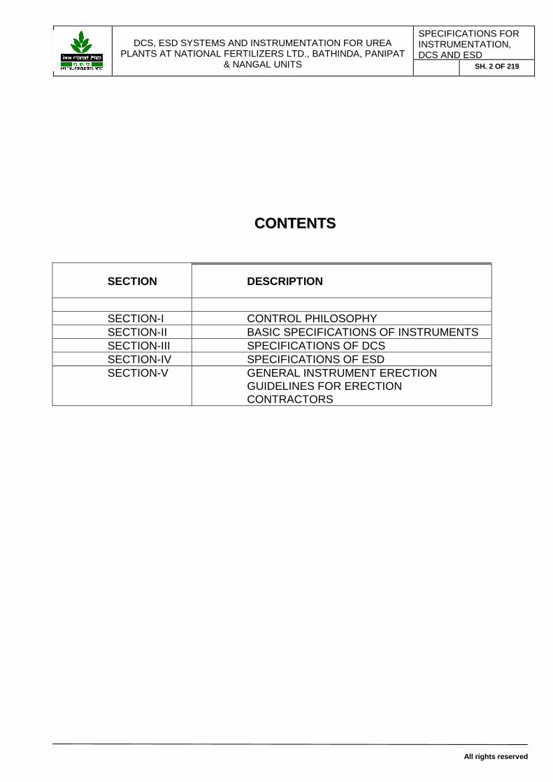
CCOONNTTEENNTTSS
SECTION DESCRIPTION
SECTION-I CONTROL PHILOSOPHY SECTION-II BASIC SPECIFICATIONS OF INSTRUMENTS SECTION-III SPECIFICATIONS OF DCS SECTION-IV SPECIFICATIONS OF ESD SECTION-V GENERAL INSTRUMENT ERECTION
GUIDELINES FOR ERECTION CONTRACTORS

DCS, ESD SYSTEMS AND INSTRUMENTATION FOR UREA
PLANTS AT NATIONAL FERTILIZERS LTD., BATHINDA, PANIPAT & NANGAL UNITS
SPECIFICATIONS FOR INSTRUMENTATION, DCS AND ESD
SH. 3 OF 219
All rights reserved
SECTION-I
Control Philosophy

DCS, ESD SYSTEMS AND INSTRUMENTATION FOR UREA
PLANTS AT NATIONAL FERTILIZERS LTD., BATHINDA, PANIPAT & NANGAL UNITS
SPECIFICATIONS FOR INSTRUMENTATION, DCS AND ESD
SH. 4 OF 219
All rights reserved
INDEX
SR. NO. TOPIC 1.0 Scope 2.0 ABBREVIATIONS Used in this document 3.0 Control and Safeguarding Systems Objectives 4.0 Control and Operation philosophy 4.1 Operation 4.2 EQUIPMENT LOCATIONS 4.3 SYSTEMS INTEGRATION 4.4 FIELD INTERFACE 4.5 POWER SUPPLY 4.6 ALARM MANAGEMENT 5.0 CONTROL AND SAFEGUARDING DESIGN
CRITERIA 5.1 EXPANDABILITY 5.2 DCS DESIGN CRITERIA 5.3 ESD DESIGN CRITERIA

DCS, ESD SYSTEMS AND INSTRUMENTATION FOR UREA
PLANTS AT NATIONAL FERTILIZERS LTD., BATHINDA, PANIPAT & NANGAL UNITS
SPECIFICATIONS FOR INSTRUMENTATION, DCS AND ESD
SH. 5 OF 219
All rights reserved
1.0 Scope
This specification outlines the instrument control philosophy of the complete Project. Covered by this specification are the DCS, ESD systems and their interfaces to other systems. This philosophy is not intended as a technical specification and is restricted to the description of the overall philosophy; detailed technical requirements are not specified. For detailed specifications, refer other sections of these documents.
Urea Instrumentation Up-gradation project involves: i) Replacement of pneumatic field instrumentation with electronic
microprocessor based instruments. ii) Replacement of stand alone pneumatic/electronic controllers with DCS iii) Replacement of Relay based trip interlock with QMR ESD system with
built-in SER of 1ms resolution. All trip interlock shall be realized through 2 out of 3 voting logic.
iv) Integration of DCS, field instrumentation, ESD system and sub-systems shall be done at site by DCS/ESD vendors.
v) DCS and ESD system shall be installed in new control room built for AFCP (Ammonia Feedstock Changeover Project). The new control room is situated approx. 500 meters away from the urea plant.
vi) Following unit specific sub-systems shall be shifted from existing urea control room to the new control room and integrated with DCS & ESD system.
(a) NFL Bathinda (1) Woodward Speed Governing system for CO2 Booster Compressor. The
system includes one 505E Controller along with its local Operating Control panel. Local panel is installed near the compressor. 505E Controller will be shifted to the new CCR. The governor shall be integrated with DCS using RS-485 connectivity which is provided in Woodward 505E controller.
Speed Signals from Two Speed Pickups will be taken to 505E Controller to be placed in new CCR. This may require use of low capacitance cables specified by M/s Woodward because of distance between speed pickups and 505E Controller. Supply of cable for 2 Nos. Pickups and integration as mentioned above, will be in supplier’s scope.
The DCS will have face faceplate of the governor to issue remote commands to Woodward 505 E controller for speed control and extraction pressure control.
Trip contacts from 505E controller shall be hard wired with ESD system.

DCS, ESD SYSTEMS AND INSTRUMENTATION FOR UREA
PLANTS AT NATIONAL FERTILIZERS LTD., BATHINDA, PANIPAT & NANGAL UNITS
SPECIFICATIONS FOR INSTRUMENTATION, DCS AND ESD
SH. 6 OF 219
All rights reserved
(2) Vibration monitoring system – Bently Nevada 3500 Series. The VMS shall be placed in the existing urea control room only. 4~20mA signals for individual channels will be hard wired to DCS. Trip contacts from VMS shall be hard wired with ESD system. The system will be integrated with DCS through RS-485 link also,
provided in the VMS, for display of all parameter on DCS. (3) Vibration velocity measurement system – Bently Nevada model
1900/55. The system shall be placed in the existing urea control room alongside the 3500 series system in the same panel. 4~20mA output from individual channels will be hard wired to DCS. Alarm/trip controls will be hard wired to ESD.
(b) NFL Panipat (4) Woodward Speed Governing system for CO2 Booster Compressor. The
system includes one 505E Controller alongwith its local Operating Control panel. Local panel is installed near the compressor. 505E Controller will be shifted to the new CCR. The governor shall be integrated with DCS using RS-485 connectivity which is provided in Woodward 505E controller.
Speed Signals from Two Speed Pickups will be taken to 505E Controller to be placed in new CCR. This may require use of low capacitance cables specified by M/s Woodward because of distance between speed pickups and 505E Controller. Supply of cable for 2 Nos. Pickups and integration as mentioned above, will be in supplier’s scope.
The DCS will have face faceplate of the governor to issue remote commands to Woodward 505 E controller for speed control and extraction pressure control.
Trip contacts from 505E controller shall be hard wired with ESD system.
(5) Vibration monitoring system – Bently Nevada make. The VMS shall be placed in the existing urea control room only. 4~20mA signals for individual channels will be hard wired to DCS. Trip contacts from VMS shall be hard wired with ESD system.
(c) NFL Nangal
Omron PLC: Only communication through fibre optic cable to be provided (cable supply in DCS vendor’s scope).

DCS, ESD SYSTEMS AND INSTRUMENTATION FOR UREA
PLANTS AT NATIONAL FERTILIZERS LTD., BATHINDA, PANIPAT & NANGAL UNITS
SPECIFICATIONS FOR INSTRUMENTATION, DCS AND ESD
SH. 7 OF 219
All rights reserved
SCOPE OF WORK DCS Vendor: Design, Engineering (including making logics and control schemes as per owner’s drawings and incorporating the same in DCS), Supply, Installation and commissioning of : 1. DCS System including operator consoles, remote consoles, engineering
workstation, printers as per details specifications as per annexure. 2. Design, engineering, and incorporation of control schemes in DCS, Co-
ordination with ESD vendor for seamless integration of DCS and ESD systems and various sub-systems as specified elsewhere in the document.
3. Field instruments as per List of Field Instruments and associated hardware given at 18.0 in section II.
4. UPS as per specifications for Bathinda and Panipat Units only along with two year spares. For Nangal Unit, UPS is available and will be provided by NFL
5. Cables, Cable Trays, structural material for cable laying as per annexure. Respective vendors should visit site to assess material requirement.
6. It is envisaged that the cables wil be laid on over ground route only. However, in case any cable is to be run underground, digging and associated work thus involved shall be in bidders scope.
7. Junction Boxes with terminal strips, cable glands, wire marking as per Annexure.
8. Fittings and associated hardware for connecting transmitter impulse pipes as per Annexure. The job involves replacement of pneumatic transmitters with electronic transmitters, providing triplicated impulse pipes for ESD transmitters, complete with Three way manifolds, isolation valves, drain valves, support of impulse lines, stanchions for mounting triplicated transmitters on 2” pipes.
9. Isolator panel cabinet complete with isolators, pre-wired and marked terminal strips, redundant power supply, cooling fans etc as per annexure.
10. Electrical interface cabinets alongwith associated hardware/modules/relays etc. to be placed in sub-station.
11. Cabinet to house sub-systems as elaborated under ‘SCOPE’ at clause 1.0 above.
12. Auxilliary console complete with annunciator, Push buttons, Led lamps, Reset switches.
13. Godrej make furniture for work stations/PCs including chairs for operators for control room and engineering room.
14. Commissioning of DCS system including field instruments in association with ESD vendor for seamless integration of both the systems.

DCS, ESD SYSTEMS AND INSTRUMENTATION FOR UREA
PLANTS AT NATIONAL FERTILIZERS LTD., BATHINDA, PANIPAT & NANGAL UNITS
SPECIFICATIONS FOR INSTRUMENTATION, DCS AND ESD
SH. 8 OF 219
All rights reserved
Commissioning job will be carried out tentatively in August 2012. The job will coincide with the commissioning of ongoing AFCP
(Ammonia Feedstock Changeover Projects) at Bathinda, Nangal and Panipat units.
Approximately 45 days shutdown will be available to carry out the total job. However installation work may be carried out beforehand in running plant wherever possible.
15. All outgoing cables for trip interlock purpose from ESD system going to
various solenoid valves, actuators, indicator lamps, drives etc shall be
in the scope of DCS vendor. Scope includes supply of cables , JB’
complete with terminal strips and glands, laying of cables, termination
at both ends i.e field JB’s and cabinets.
16. Documentation 17. Spare Parts 18. Training for operation and maintenance staff. 19. Comprehensive AMC (without resident engineer) for five years after
expiry of the warranty period with minimum five visits (including emergency & periodic visits) of the service engineer per year. The AMC shall include supply, replacement / repairs of all the system modules / cards etc. All the software problems / up gradations shall have to be taken care of by the vendor.
ESD Vendor: Design, Engineering (including making logics and control schemes as per owner’s drawings and incorporating the same in ESD), Supply, Installation and commissioning of : 1. ESD System including operator consoles, engineering workstation, ESR
PC, printers, as per annexure. 2. Design, engineering, and incorporation of process and safety interlock
schemes in ESD as per schematics provided by NFL, Co-ordination with DCS vendor for seamless integration of DCS and ESD systems and various sub-systems as specified elsewhere in the document.
3. Godrej make furniture for work stations/PCs including chairs for operators for control room and engineering room.
4. Commissioning of ESD system in association with DCS vendor for seamless integration of both the systems. Commissioning job will be carried out tentatively in August 2012.

DCS, ESD SYSTEMS AND INSTRUMENTATION FOR UREA
PLANTS AT NATIONAL FERTILIZERS LTD., BATHINDA, PANIPAT & NANGAL UNITS
SPECIFICATIONS FOR INSTRUMENTATION, DCS AND ESD
SH. 9 OF 219
All rights reserved
The job will coincide with the commissioning of ongoing AFCP (Ammonia Feedstock Changeover Projects) at Bathinda, Nangal and Panipat units.
Approximately 45 days will be available to carry out the total job. However installation work may be carried out beforehand.
5. All outgoing cables for trip interlock purpose from ESD system going to
various solenoid valves, actuators, indicator lamps, drives etc shall be in the scope of DCS vendor. Scope of cables includes supply of cables , JB’ complete with terminal strips and glands, laying of cables, termination at both ends i.e field JB’s and cabinets.
6. Documentation – as per annexure 7. Spare Parts – as per annexure 8. Training for operation and maintenance staff. 9. Comprehensive AMC (without resident engineer) for five years after
expiry of the warranty period with minimum five visits (including emergency & periodic visits) of the service engineer per year. The AMC shall include supply, replacement / repairs of all the system modules / cards etc. All the software problems / up gradations shall have to be taken care of by the vendor.
DCS & ESD System Integration Methodology: 1) All signals from transmitters shall be brought to the cabinet room in new
control room. Signals which are common with ESD will be terminated in isolator panel. Isolator panel will comprise of P&F/MTL/Stahl make of isolating signal multipliers. Each isolator signal multiplier shall have one input and two outputs. One output will be hardwired to DCS and the other to ESD System. DCS vendor will wire up both the outputs from signal multipliers to separate terminal strips; one each meant for signals for DCS and signals for ESD respectively. ESD vendor will wire up signals for ESD panels from this terminal strip. Where trip is involved, for 2oo3 logic philosophy for ESD, signals for three field transmitters will come to isolator signal multipliers. All the three signals will be routed to DCS also and median of the three will be used for control.
DCS and ESD system will also be integrated through a redundant RS-485 link so as to have all information of ESD available on DCS. However no write commands shall be possible from DCS to ESD. Engineering Stations for DCS and ESD systems shall be separate. There should not be a common data base.

DCS, ESD SYSTEMS AND INSTRUMENTATION FOR UREA
PLANTS AT NATIONAL FERTILIZERS LTD., BATHINDA, PANIPAT & NANGAL UNITS
SPECIFICATIONS FOR INSTRUMENTATION, DCS AND ESD
SH. 10 OF 219
All rights reserved
2.0 ABBREVIATIONS Used in this document: CPU = Central Processing Unit DCS = Distributed Control System ESD = Emergency Shutdown System HMI = Human Machine Interface MCC = Motor Control Centre CCR = Central Control Room MOS = Maintenance Override Switch POS = Position/operation override switch MS = Microsoft OPC OLE = (Object Linking and Embedding) for Process Control PLC = Programmable Logic Controller SER = Sequence of Events Recorder TÜV = Technische Überwachsungs Verein VDU = Video Display Unit ( Always 21” square model or 24”
wide screen TFT /LCD type colour monitor)
3.0 Control and Safeguarding Systems Objectives: The main objective of the plant and its control system is to, safely and reliably, continuously produce on-specification product. Without compromising these objectives, the control systems shall also be designed to maximize plant availability, minimize plant energy consumption, adverse environmental impact and requirements for operator interventions. The principle objective of the safeguarding systems is the protection of personnel, environment, plant and equipment and the maintenance of safe operating conditions compatible with production requirements. This shall result in control and safeguarding system design that is: - Safe - Simple to maintain - Simple to operate - Flexible to accommodate changes in technology and operating
requirements - Flexible to provide for expansion during 30 year design life - Reliable
4.0 Control and Operation philosophy:
4.1 Operation: 4.1.1 All process and utility units and related facilities for the entire plant
shall be monitored and controlled from the Central DCS located at Central Control Room. Every major and minor unit of the plant shall be operated independently from dedicated console, consisting of VDU-

DCS, ESD SYSTEMS AND INSTRUMENTATION FOR UREA
PLANTS AT NATIONAL FERTILIZERS LTD., BATHINDA, PANIPAT & NANGAL UNITS
SPECIFICATIONS FOR INSTRUMENTATION, DCS AND ESD
SH. 11 OF 219
All rights reserved
based DCS operator interfaces, and ESD system. All of these VDU’s shall be 21” square model or 24” wide screen TFT /LCD type colour monitor only. Conventional CRTs are not acceptable.
4.1.2 The DCS operator interface (VDU based) shall be the primary
integrated window for operation of the control and safeguarding systems and shall provide access to:
- Process control - Sequence control status - Equipment status - Alarm overview - Trip status overview (This shall be via ESD SER PC, located at
Central Control room.) - Override status (Soft POS/MOS switches visible on PC console
and DCS graphic via ESD) - Real-time trending - Historical data trending - Generation of dynamic graphics as per process requirement - Machine Monitoring
4.1.3 All control and interlocks shall be monitored, controlled, and engineered through work stations as given below
DCS: Four operator stations. (3 in CCR and 1 in shift in-charge room) Consoles to be placed in the CCR will be Double tier type.
Two Engineering stations.
Two remote operator stations in the plant. These stations shall be placed in Urea plant situated approximately 500 meters from the CCR.
One 72” wall mountable type console for process overview in the CCR.
ESD: Two Engineering work stations.
One operator HMI station which will have soft bypass switches (POS/MOS, Position override and maintenance override) and all relevant data for the operator like ESR reports, alarm summaries etc.
One dedicated PC for ESR reports generated by ESD.
4.1.4 All consoles for DCS and ESD shall be supplied with latest 21” square model or 24” wide screen TFT /LCD type colour monitors.

DCS, ESD SYSTEMS AND INSTRUMENTATION FOR UREA
PLANTS AT NATIONAL FERTILIZERS LTD., BATHINDA, PANIPAT & NANGAL UNITS
SPECIFICATIONS FOR INSTRUMENTATION, DCS AND ESD
SH. 12 OF 219
All rights reserved
4.1.5 All controls and interlocks of the complete plant, shall be performed / realized in the central DCS/ESD only.
4.1.6 Comprehensive facilities are to be provided to ensure that the operators at all times have complete overview of the plant status from the HMI . Information will be presented in the form of ‘live’ graphic displays and simulated instrument faceplates. The system shall be configured to permit the operator to determine the cause of an alarm with a minimum of keystrokes at the console, without having to memorise tag numbers, so that a rapid reaction to an abnormal situation can be achieved.
4.2 EQUIPMENT LOCATIONS 4.2.1 All DCS/ESD operator stations, auxiliary hardwired console shall be
located in central control room of AFCP (Ammonia feedstock changeover project). Central control room is situated approximately 500 meters from Urea plant.
4.2.2 All DCS/ESD marshalling cabinets, System hardware cabinets, etc.
shall be located in central cabinet room of AFCP (Ammonia feedstock changeover project) situated approximately 500 meters from Urea plant.
4.2.3 Existing subsystems such as Bently Nevada Vibration Monitoring
system, Woodward Governor system, Anti-surge control system for the turbo machinery etc. system’s secondary hardware shall also be located in the same type of cabinet in central cabinet room.
4.2.4 DCS engineering stations, ESD engineering station, all other
programming PC/Engineering station of other type control systems, etc. shall be located in central engineering room which will be in the close vicinity of central cabinet room and central control room. ESD HMI station having MOS/POS (maintenance override station/position override station for ESD will be located in CCR.
4.2.5 All IRC (Interposing Relay Cabinets or Digital Interface cabinet) and
IFC (Interface cabinet or simply Analog Interface Cabinet) between Electrical and Instruments shall be located in central cabinet room only. However isolator panel for analog signals from electrical motor currents will be placed in electrical sub-station.
4.2.6 All DCS/ESD and other control systems’ Panel shall be openable from
front and back side. The relevant DCS/ESD hardware shall be installed in dedicated panels. The panel make/model/size is specified in detail specification of DCS/ESD. There shall be panel segregation for various I/Os meant for DCS and ESD system. Also there shall be

DCS, ESD SYSTEMS AND INSTRUMENTATION FOR UREA
PLANTS AT NATIONAL FERTILIZERS LTD., BATHINDA, PANIPAT & NANGAL UNITS
SPECIFICATIONS FOR INSTRUMENTATION, DCS AND ESD
SH. 13 OF 219
All rights reserved
panel segregation for diff. type of I/Os for DCS, ESD and other control systems. This means that analog input and analog output shall be accommodated in a separate marshalling panel/DCS/ESD panel. Digital input shall be accommodated in a separate marshalling/DCS/ESD panel. Digital output and all interposing relays shall be accommodated in separate panels.
4.2.7 All the various system earth pits like System Ground, Safety Ground,
Intrinsic ground, etc. shall be constructed in the peripheral area of cabinet room outside the control/cabinet room building. If the required earth pit resistance is not achieved with one earth pit, there shall be multiple earth pit connected in parallel. Similarly, if different system requires different earth pits, there shall be a group of multiple earth pits in the area outside the control room/cabinet room.
4.3 SYSTEMS INTEGRATION 4.3.1 The vendors of DCS and ESD systems shall engineer the systems as
one integrated control and safeguarding system with respect to operator presentation. The systems shall be brought ready for integration at site. DCS and ESD vendors will list out and share various requirements such as I/O’s communication ports etc for seamless integration of DCS and ESD at site. The DCS HMI shall be the single operating window for integrated control and safeguarding system. Communications of the ESD with the DCS shall be accomplished via dedicated redundant, single fault tolerant serial links.
4.3.2 An Open Control Systems Network shall allow the integrated control
and safeguarding system to communicate with third party control systems, auxiliary information systems and higher-level automation systems utilizing OPC connectivity standards. Although APC is not envisaged immediately, The DCS shall have the capability to be seamlessly integrated with an APC whenever required. Special attention shall be given to network security of the Open Control Systems Network. Firewall shall prevent unauthorized access from the office network to the Open Control Systems Network.
4.3.3 It shall be possible to connect with the integrated control and
safeguarding system with redundant OPC servers. 4.3.4 Although the DCS and ESD systems are to be engineered as an
integrated control and safeguarding system, each system shall have its own connection to the Open Control Systems Network.

DCS, ESD SYSTEMS AND INSTRUMENTATION FOR UREA
PLANTS AT NATIONAL FERTILIZERS LTD., BATHINDA, PANIPAT & NANGAL UNITS
SPECIFICATIONS FOR INSTRUMENTATION, DCS AND ESD
SH. 14 OF 219
All rights reserved
4.3.5 DCS vendor will supply All IRC (Interposing Relay Cabinets or Digital Interface cabinet) and IFC (Interface cabinet or simply Analog Interface Cabinet) between Electrical and Instruments. These shall be located in central cabinet room only.
However isolator panel for analog signals from electrical motor currents will be placed in electrical sub-station. Electrical analog signals are available in electrical sub-station. DCS vendor will supply Electrical interface cabinets alongwith associated hardware/ modules/relays etc to be placed in sub-station.
4.4 FIELD INTERFACE
Multi- core cables connected to junction boxes in the field, transmitting conventional 4-20 mA signals from all type of field transmitters, individually, will be connected to marshalling racks. In the marshalling racks the signals will be connected to the I/O cards of the DCS and ESD systems through pre-fab system cables.
4.5 POWER SUPPLY
Independent, Redundant 115VAC UPS power supply feeders shall be provided by vendor for DCS as well as ESD systems at one point respectively. From there the power shall be routed to respective systems (ESD and DCS) by the respective vendors through their PDBs. PDB panels shall be of the same size/make and model like DCS/ESD panels. The 24 V DC redundant power supply shall be generated from these 115 V AC UPS supply by individual system vendors, wherever it is required. These shall also be accommodated in the panels at central cabinet room, having the same specifications of panels.
For Nangal unit, 110V AC Power Supply for Solenoid valves of Urea plant shall be wired from PDB in AFCP cabinet room. For Bathinda and Panipat units, 110 DC power for Solenoid valves of Urea plant is available in the existing Urea control room. Vendor shall provide a pre-wired relay cabinet each with 60 Nos. 24VDC relays.
4.6 ALARM MANAGEMENT
The purpose of an alarm is to bring the operator's attention to an abnormal event, such that he can take action to rectify the situation. During normal operation the Alarm Philosophy shall be that there are no active alarms present. To enable the operator to respond

DCS, ESD SYSTEMS AND INSTRUMENTATION FOR UREA
PLANTS AT NATIONAL FERTILIZERS LTD., BATHINDA, PANIPAT & NANGAL UNITS
SPECIFICATIONS FOR INSTRUMENTATION, DCS AND ESD
SH. 15 OF 219
All rights reserved
appropriately, alarms shall be categorized according to the following three priorities reflecting the severity of the abnormal situation, as a minimum
- An ESD alarm is an indication that a trip has occurred. A "First
Failure" indication shall discriminate between related ESD alarms to identify the first initiator of a trip with 1 mili second time resolution on SER PC monitor located at central cabinet room in the operator console.
- A shutdown level alarm indicates that immediate operator action is
required to prevent a trip condition (in this case it is also referred to as a pre-alarm), or is used for essential parameters for proper operation of the plant (e.g. quality alarms) in DCS operator console with diff. hooter/sound.
- Secondary alarms draw only attention to an abnormal situation that could result in a severe operational upset if not acted upon. This shall also be reported at DCS operator station with diff. hooter /sound
Alarm acknowledgement and first failure resetting shall be from the DCS keyboard, not locally from equipment panels or solenoids.
On measurements that can lead to a trip, pre-alarms shall be implemented.
The alarm management of the DCS shall be developed with the following objectives: - Minimize the number of active alarms; - Optimize the information contained in the alarms; - Obtain effective alarm presentation by using Human Factor
design principles and practice.
Further techniques shall be employed to optimise the operator interface to the alarm system. The DCS shall be compliant with Alarm Management standards EEMUA 191 and ISA-18.02. Methods to be used are suppression techniques (static or dynamic), first failure indication and alarm overview displays in addition to the alarm list. The overview displays provide a layered structure of related alarms in annunciation screens.

DCS, ESD SYSTEMS AND INSTRUMENTATION FOR UREA
PLANTS AT NATIONAL FERTILIZERS LTD., BATHINDA, PANIPAT & NANGAL UNITS
SPECIFICATIONS FOR INSTRUMENTATION, DCS AND ESD
SH. 16 OF 219
All rights reserved
An ESD based Sequence of Events Recording system shall log all safety related alarms, commands and status changes for post-trip analysis on a dedicated ESR PC station.
5.0 CONTROL AND SAFEGUARDING DESIGN CRITERIA 5.1 EXPANDABILITY 5.1.1 In I/O Count for DCS & ESD, 20% spare capacity has been
considered. This minimum 20% spare capacity shall be provided in each of the I/O cards in the form of spare channels. This spare capacity should be completely pre-wired with all the intermediate accessories like pre-fab cable, cable connector, barrier / isolator/relay up to marshalling terminal.
5.1.2 No I/O module in DCS & ESD shall be loaded more than 80%, 5.1.3 In addition, minimum 20% spare space in cabinets for installation of
spare I/O cards shall be available throughout the system for allowing undefined future expansion.
5.1.4 To allow for future expansion 20% spare capacity shall be allowed &
terminated in multi core cables, junction boxes, etc, marshalling racks, patch panels and power supply units.
5.1.5 Communication networks and cables shall have a spare load capacity
of 50% as a minimum. 5.1.6 Plant wide networks shall have a node connection spare allowance of
50 % as a minimum. 5.1.7 Local networks, if any, shall have a node connection spare allowance
of 30 % as a minimum. 5.2 DCS DESIGN CRITERIA 5.2.1 The DCS, by employing distributed intelligence and database
techniques, shall provide highly secure, safe, reliable, maintainable, effective process / safety monitoring and control of the production/ancillary facilities, from a permanently manned Central Control Room (CCR). DCS shall not be a PLC/SCADA based system. PLC Hardware like CPU, I/O modules etc. in any form are not acceptable in DCS.

DCS, ESD SYSTEMS AND INSTRUMENTATION FOR UREA
PLANTS AT NATIONAL FERTILIZERS LTD., BATHINDA, PANIPAT & NANGAL UNITS
SPECIFICATIONS FOR INSTRUMENTATION, DCS AND ESD
SH. 17 OF 219
All rights reserved
5.2.2 The system shall enable process monitoring, control, safety detection & protection to be achieved, at several equipment nodes, with serial high-speed communications to the operator's console employing VDU's, keyboards, print server & printer, data storage devices, etc. All VDU shall be standard 21” square model or 24” wide screen TFT /LCD type colour monitor.
5.2.3 The DCS & Safety Systems shall employ Dual redundant (single fault
tolerant) communications links. The system supplier shall prove that the system hardware redundancy, will achieve an availability figure better than 99.99% per control loop using his chosen hardware configuration.
5.2.4 Process and sequential control shall be achieved using plant wide
multi-loop microprocessor based digital controllers, with full functional interfaces being provided by the operator's consoles.
5.2.5 Minimum Two sets of controllers are envisaged for DCS. Controllers
should not be loaded more than 60%. If more number of controllers are required to meet 60% controller loading criteria, the same should be included.
5.2.6 The operator's VDU/keyboards shall provide MS windows HMI. All
VDU shall be 21” square model or 24” wide screen TFT /LCD type colour monitor as a minimum.
5.2.7 The system shall be fully configurable without specialized
programming knowledge, using proven, fully de-bugged and tested Supplier's standard software packages. Sufficient online storage shall be included to accommodate the database and alarm, event and historic data logs. To achieve the reliability/availability targets required, redundancy requirements shall be calculated and employed. Operational control of the plant will normally be from the CCR. Facilities shall be provided such that in the event of failure of operator workstations, the controllers shall continue to provide control operation at the last known set point.
5.2.8 The system shall be built on the latest state-of- the-art hardware and
software platform and hardware/software/firmware revisions of complete system will be latest at the time of supply. The system architecture shall have Microsoft Windows (latest version) operating systems and compatible RISC hardware. All the operator station and engineering station shall equipped with 21” square model or 24” wide screen TFT /LCD type colour monitor. Conventional CRTs are not acceptable. Number of consoles envisaged is indicated elsewhere in this document. There shall be a facility to operate these loops from the adjacent Operator station in case of any failure.

DCS, ESD SYSTEMS AND INSTRUMENTATION FOR UREA
PLANTS AT NATIONAL FERTILIZERS LTD., BATHINDA, PANIPAT & NANGAL UNITS
SPECIFICATIONS FOR INSTRUMENTATION, DCS AND ESD
SH. 18 OF 219
All rights reserved
Client Server Architecture is not acceptable. All Workstations should be directly sitting on Plant Communication Loop as INDEPENDENT NODES. No operating Station should be connected to Plant communication loop through a server. All workstation should be directly connected to main Plant communication loop as independent nodes with full functionality.
However, “remote monitoring stations" which are meant for remote operation/ monitoring can be connected to plant communication loop through server in case distance is a limitation for Server-Server configuration.
5.2.9 The system shall be 100% fault tolerant and dual redundant for
control processor, system bus, data highway, I/O for closed loops, power supply and communication. This means, all central control processors, all communication processors and all other central rack and individual node’s common cards, all the communication cards, networks and cables, etc. shall be 100% fault tolerant.. All the hardware including control/communication processors, networks, cables, all type of system cards, all type of I/O cards shall be hot replaceable.
5.2.10 All the I/O cards shall have individual channel to channel as well
channel to field isolation. Analog input/output cards shall be galvanically isolated and digital input/output cards shall be optically isolated. Group isolated type or bulk I/O cards shall NOT be accepted in the whole system architecture. All I/O cards shall be intelligent type with microprocessor/microcontroller based hardware and capable of all type of signal conditioning, self diagnostic, fail safe value configurable (programmable) and time stamping at I/O card level.
5.2.11 I/O cards’ Channel density shall not exceed the following limits
Analog Input – 16 Channels Analog Output – 8 Channels Digital Input -16 Channels Digital Output -16 Channels
All I/O cards in individual category shall be of same type/model/revision only. No different bulk I/O cards or I/O cards with degraded features shall be accepted in any of the category in a mix mode supply.
5.2.12 The scan time of all type of analog/digital inputs cards & DCS
algorithm (Scan time means the sum of total time required for reading

DCS, ESD SYSTEMS AND INSTRUMENTATION FOR UREA
PLANTS AT NATIONAL FERTILIZERS LTD., BATHINDA, PANIPAT & NANGAL UNITS
SPECIFICATIONS FOR INSTRUMENTATION, DCS AND ESD
SH. 19 OF 219
All rights reserved
an input, running control algorithm and writing the output values) shall be better than 250 milli-seconds for any type of channel.
5.2.13 There shall be minimum 2 nos. of engineering station
software/personalities in overall DCS architecture, from where the complete DCS project can be developed and deployed on any other operator/control station, independently. Non-availability of both of these engineering stations simultaneously shall not affect the plant normal operation and shall neither cause any historical/trend data loss. All operator station shall be independent of engineering stations, self bootable and do not require engineering station for putting them into normal operation or restoring them after rebooting, once the developed project is deployed. System should allow on-line modification, addition / deletion or change in any control loop or part thereof.
5.2.14 All operator stations and engineering stations shall be OPC compliant
without any upper limit on number of tags. However, if there is any specific limit applicable on the proposed system, it is to be specified.
5.2.15 Complete system hardware/software and communication load shall
not exceed 50% system load even after the complete implementation of project and running at peak load. This includes redundant control processor load also.
5.2.16 System shall have 50% spare margin in software memory/load for
future spare addition without replacing/upgrading any existing system hardware/software at all the levels. System shall be capable of loading up to 100% without any overrun/degradation of performance, etc. System shall report all type of load limit alarms, diagnostic alarms upto channel level, communication alarms, system hardware failure alarm and other global information with alarm facility on engineering/operator station in real time with 1 second resolution.
5.2.17 The system shall support all various type of
control/interlock/sequence algorithm and shall also support various high level programming language like VB, C/C++ in real time control application, in addition to standard control algorithms available in the DCS.
5.2.18 System shall support various Hourly/Shift/Daily/Monthly Reports/Logs,
Totalizers reports, SNAP shot reports, etc. in Microsoft excel format only. The layout and type of reports/data, nos. of tags per report, etc. shall be as per owner’s requirement. All the operator station, engineering stations shall be equipped with MS Office licensed copy. System shall support history for min. 5000 tags, out of which 2000 points shall be configurable for 1 second resolution, 1000 points shall be configurable for 2 seconds interval and remaining shall be

DCS, ESD SYSTEMS AND INSTRUMENTATION FOR UREA
PLANTS AT NATIONAL FERTILIZERS LTD., BATHINDA, PANIPAT & NANGAL UNITS
SPECIFICATIONS FOR INSTRUMENTATION, DCS AND ESD
SH. 20 OF 219
All rights reserved
configurable from 5 to 10 seconds. There shall be no limit on history data retention time, except the hard disk size. All the stations, wherever engineering database of complete project and historical/run time data is stored, shall be equipped with redundant hard disk with RAID1 configuration, to prevent any data loss. This will include not only the engineering station but all the operator station also, wherever applicable.
5.2.19 System shall support 1 second time resolution real time trend for all
the system tag/parameters, without any time limit. The minimum x –axis time span for real time trend with 1 second sample rate shall be 30 minutes. Also, all PID loop face plate display shall have real time/historical trend window by default for min. three parameters, i.e. measured or process variable, operator entered or remote/calculated set-point and output value or manipulated value for that particular loop.
5.2.20 DCS system shall have latest; windows based alarm manager with 1
second or better time resolution. In addition to various process alarms, the system shall also store operator action journal, system error messages, any other event, etc. Alarm manager shall also have historian facilities and there shall not be any storage limit except hard disk size for retention period of various alarms/events.
5.2.21 Complete system hardware shall be certified for ISA G3 class
corrosion level protection and shall be compatible with various RFI/EMI immunity as per IEC. The complete system shall be supplied with either 1200 mm (W) x 800 mm (D) x 2100 mm (H) or 800 mm (W) x 800 mm (D) x 2100 mm (H) standard RITTAL make panels with RAL7032 colour shade. Marshalling philosophy and panel segregation for various type of I/O shall be as per Owner’s requirement, which is already described above.
5.2.22 DCS system shall have fast MODBUS I/O cards/Communication
gateways for interconnecting with ESD systems and other various types of control systems like Speed/Vibration monitoring system, etc. via RS485 interface and MODBUS protocol. The link shall be one way, i.e. the information in DCS shall be used as view only purpose. No remote writing facilities from DCS to other system via MODBUS are permissible. The communication module and links shall be 100% fault tolerant. The signal exchange between various other system and DCS shall be hardwired if they are to be used for control/decision making purpose in DCS. All serial links shall be connected to dedicated gateways/cards. These gateways shall be independent and not combined with process controllers. Serial cards shall be redundant.

DCS, ESD SYSTEMS AND INSTRUMENTATION FOR UREA
PLANTS AT NATIONAL FERTILIZERS LTD., BATHINDA, PANIPAT & NANGAL UNITS
SPECIFICATIONS FOR INSTRUMENTATION, DCS AND ESD
SH. 21 OF 219
All rights reserved
5.2.23 Vendor shall provide 115 V AC +/- 10% at 50 Hz -3/+1 Hz, UPS grade, floating power supply for complete DCS system at one location in cabinet room up to PDB panels. All digital input shall have 24 V DC interrogation voltage level. All Analog cards shall be capable of accepting 2 wire and 4 wire analog inputs and shall supply 24 V DC to field transmitters. All Digital output cards shall drive 24 V DC, OMRON make, 4 NO/NC, socket mounted, interposing relays with 230 VAC/5 Amp contact ratings. All field loads from Digital Output cards, including Solenoid valves, MCC switch gear signals, etc. shall be interfaced via these interposing relays only. The digital output cards driving the MCC related output relays ( which are to be wired to MCC/Sub station) shall be accommodated in Digital Interface panel as specified above, separately to avoid any interference problems in low voltage instrument signal cables. There shall be intrinsically safe active barriers of MTL3000 series / P&F make for analog inputs & outputs, and all NAMUR sensors (proximity switches).
5.2.24 For various categories of I/O cards, 20% (minimum one set where 20% works out to be less than one) of each type of spare I/O modules as ware house spares shall be considered. These spare modules shall also include related termination assembly, isolating barriers and all system pre-fab cables. For modules, (controllers, communication modules, power supplies etc.) which are specified as redundant, 20% ware house spares shall be considered or 1 pair of each type if 20% works out to be less than one. Spare parts criteria is elaborated at point no.10.2.2. of Section III (DCS specifications)
5.2.25 The offered system shall be supported by the DCS vendor for min. 15
years for all type of hardware and software spares and service supports. 5.2.26 While preparing DCS database, all configuration like graphic symbols,
colour codes, control/logic schematics, etc. shall be based on ISA standards.
In case of any conflict between above general requirement/guide lines, the more stringent DCS specifications will be followed. 5.3 ESD DESIGN CRITERIA 5.3.1 The safeguarding system shall automatically bring the relevant
equipment or part of the plant to a safe condition, when a critical process variable reaches the limit of an acceptable control value.
5.3.2 Safeguarding systems shall work independently of the control system
with their own initiating and actuating devices. Process variables used for safeguarding shall be directly measured where possible.

DCS, ESD SYSTEMS AND INSTRUMENTATION FOR UREA
PLANTS AT NATIONAL FERTILIZERS LTD., BATHINDA, PANIPAT & NANGAL UNITS
SPECIFICATIONS FOR INSTRUMENTATION, DCS AND ESD
SH. 22 OF 219
All rights reserved
5.3.3 The ESD System will be based on a fault tolerant programmable
system design and will utilize 2oo3 logic using QMR Programmable Logic Controllers. The system may be sub-divided into sub-systems for example processing trains and common facilities etc. The system shall be designed, manufactured, tested and commissioned to comply with the requirements of IEC 61508/61511. The ESD system shall be approved for use in SIL 3 classified loops.
5.3.4 The system operating program shall be resident on EEPROM / Flash
ROM memory. The central processing units should contain the application program in non-volatile memory. Each processor must maintain 40% spare memory after configuration to allow future expansion.
5.3.5 ESD Safety critical signals shall comply with the following:
• Signals to/from the ESD shall be hardwired always. • ESD circuits shall be de-energized to trip and be "fail safe". • In the whole system there shall not be any Non-safety
signals/cards, used. Barriers to be used as per area classification. • Soft bypass switches (POS/MOS, Position override and maintenance
override) and all relevant data for the operator like ESD generated ESR reports, alarms etc.
• Hardwired critical circuits shall be arranged in such a way that probable failures e.g. cable / termination faults, power supply loss, etc. will not cause shutdowns or prejudice the systems safety integrity.
• A 2 Out of 3 Sensor philosophy shall be used for all trips. • All the interlocks in ESD shall be realized by 4-20 ma , 24 V DC, 2
wire transmitters. • The processing cycle time shall be compatible with the
requirements from the process safety time and the required resolution of the sequence of events recorder, but shall be as a maximum, including 30% processor spare capacity and taking I/O spares in account, <250 mSec.
5.3.6 The ESD panels and all system hardware shall be located at a new
central cabinet room in the close vicinity of new Central control room. This cabinet room shall accommodate all marshalling panels, PDB panels, ESD hardware panels, Barrier panels, relay panels, other control package unit hardware panels e.g. Bently Nevada vibration monitoring system panels, WOODWARD Digital Governor Panels, Speed system panels, Anti-surge control system for turbo machinery etc. All these panel size/make/model shall either 1200mm (W) x 800 mm (D) x 2100 mm(H), or 800mm (W) x 800 mm (D) x 2100 mm(H), ( size will be based on requirement), RITTAL make with RAL7032
DCS, ESD SYSTEMS AND INSTRUMENTATION FOR UREA
PLANTS AT NATIONAL FERTILIZERS LTD., BATHINDA, PANIPAT & NANGAL UNITS
SPECIFICATIONS FOR INSTRUMENTATION, DCS AND ESD
SH. 23 OF 219
All rights reserved
colour shade, as specified below. All the field instrument signal/power and control cables shall be brought to this central cabinet room, from where it shall be catered to different individual destination marshalling panels and corresponding ESD hardware panels. There shall be dedicated marshalling panels for ESD. Also, diff. type of signal category shall have different marshalling cabinets. There shall be 20% space margin available in all the panels on marshalling and relevant system hardware side panels.
5.3.7 All ESD and other control systems’ Panel shall be openable from front
and back side. The relevant ESD hardware shall be installed in dedicated panels. The panel make/model/size is specified in detail specification of ESD. There shall be panel segregation for various I/Os meant for DCS and ESD system.
5.3.8 All signals from transmitters shall be brought to the cabinet room in
new control room. Signals which are common with ESD will be terminated in isolator panel. Isolator panel will comprise of P&F/MTL/Stahl make of isolating signal multipliers. Each isolator signal multiplier shall have one input and two outputs. One output will be hardwired to DCS and the other to ESD System. DCS vendor will wire up both the outputs from signal multipliers to separate terminal strips; one each meant for signals for DCS and signals for ESD respectively. ESD vendor will wire up signals for ESD panels from this terminal strip.
5.3.9 The emergency shut down system shall be independent of DCS. It
shall be a state-of-the-art, Programmable Logic Controllers with Quadruple Modular Redundancy (QMR) based Fail Safe architecture. Irrespective of process hazards/safety class, the ESD (Emergency Shutdown System) or ESD system shall be certified for Safety Class –AK- 6 as per TUV and DIN19250/VDE0801 and SIL3 as per IEC61508 (without limitation in repair time on single point error) as a minimum. The complete application cycle time of ESD / ESD shall be less than the 25% of the Process Safety Time, when system is fully loaded and running at peak load. ( i.e. if Process safety time is 1 second, complete application cycle time of proposed safety ESD shall not be more than 250 milliseconds)
5.3.10 In general, all the trips/interlocks shall be realized thru’ 2 wire, 4-20
mA, SMART transmitters. 5.3.11 The system shall have the latest state-of-the-art architecture and the
hardware and software platform and hardware/software/firmware revisions of complete system will be latest at the time of supply.

DCS, ESD SYSTEMS AND INSTRUMENTATION FOR UREA
PLANTS AT NATIONAL FERTILIZERS LTD., BATHINDA, PANIPAT & NANGAL UNITS
SPECIFICATIONS FOR INSTRUMENTATION, DCS AND ESD
SH. 24 OF 219
All rights reserved
5.3.12 The programming environment of ESD shall be Object Oriented, Microsoft Windows based with all GUI features. Programming language supported shall conform to IEC1131 and as a minimum; it should support Function Block Diagram method, structured text method and ladder logic method. Programming environment should support generic program and running of multiple instances of the same program with diff. set of input/outputs parameters. This engineering station shall be accommodated in the central engineering room, located in the close vicinity of Cabinet room.
5.3.13 ESD system application software shall allow incremental download to
carry out online modifications, without affecting the running plant. There shall be facilities to monitor the running logic in FBD format in real time mode from engineering station. Also the engineering station of ESD shall allow forcing of any of the hardware input/output or intermediate local variables in complete system by software method.
5.3.14 ESD system should have emulator facilities, whereby any logic
function diagram generated by user can be emulated before final simulation/download to main processor.
5.3.15 ESD system must have Sequence of Event software running on a
dedicated PC with Windows GUI features, to find out the cause of the trip with 1 milli-second time resolution. Storage of various system alarms, process events with proper time stamp with 1 milli-second resolution and sorting, exporting various event reports into Microsoft Excel, Access or DBF format is a must for later on analysis of any event/trip. This SOE PC shall be located near operator station in the central control room to have round the clock access by operation group. SOE summary display should be available on every DCS operator station with no limitation on number of tags or points.
5.3.16 ESD shall have facilities to communicate with proposed DCS and
preferably it should sit on DCS network as one of the DCS node, so that seamless integration of DCS - ESD could be achieved. All ESD events shall be monitored on DCS in graphical environment via this software communication link over MODBUS or better solution as prescribed above. These include the entire Digital input/output channel’s real time status, intermediate local/global ESD variables, timers, counters, all the analog input channels real time values in floats, etc. There shall not be any tag/parameter limits on DCS/ESD gateway communication and the update time of complete ESD parameter sets on DCS shall not take more than 1 second.
5.3.17 The interface between ESD main processor and programming station
PC shall be via Ethernet with min. 100 MBPS speed.

DCS, ESD SYSTEMS AND INSTRUMENTATION FOR UREA
PLANTS AT NATIONAL FERTILIZERS LTD., BATHINDA, PANIPAT & NANGAL UNITS
SPECIFICATIONS FOR INSTRUMENTATION, DCS AND ESD
SH. 25 OF 219
All rights reserved
5.3.18 ESD program will reside in Flash ROM in ESD main processor/memory cards. Downloading in one of the central part of a QMR system shall educate the remaining CPUs and equalize the memory/data of other redundant components in the system.
5.3.19 For a group of interlocks, having common cause of trip, shall be
grouped together and will drive a digital output channel from ESD, which will be wired to Central Control room located auxiliary console lamp. Once after actuation of a trip, the final output shall not resume, unless all the input parameters are normal and operator presses a RESET button. The ready to reset condition (healthiness of all input parameters) shall be indicated to operator from above mentioned lamp. Also the RESET push button switch shall be hard wired to ESD from auxiliary console.
5.3.20 ESD shall have 4-20 ma Analog input cards (capable for accepting 2
wire transmitter signals and capable of powering up 24 V DC , 2 wire field transmitters), 24 V DC Digital Input cards and 24 V DC Digital output cards only. All the I/O cards and all the central part hardware of complete ESD system shall be fully redundant and fault tolerant. All I/O cards shall have microprocessor/microcontroller based architecture and intelligent with full diagnostic feature up to individual channel level with time stamping of 1 milli second time resolution. All I/O Modules shall be of fail safe type. NO Non-fail safe modules shall be installed anywhere in the proposed ESD system.
5.3.21 All the Digital output cards shall drive 24 V DC , OMROM make , 4
NO/NC, socket mounted Interposing relays located in a dedicated relay panels having the same specifications as that of ESD hardware panels. All digital output, be it either Solenoid valves or MCC output, shall be driven via interposing relays only. The contact rating for interposing relays shall be 230 V AC/5 Amps. All the Relays pertaining to MCC shall be installed in MCC Digital Interface cabinet and other process interlock relays like Solenoid and other loads shall be mounted in a separate Relay Panels.
5.3.22 If there is a solenoid valve installed on the control valve and if this
solenoid valve is driven by ESD logic/interlocks via Digital Output cards/interposing relay, there shall be another Digital Output channel /interposing relay configured in ESD for using the same interlock output as secondary means of de-energizing in DCS for that particular PID loop. This means, on actuation of trip logic, the ESD shall close the control valve with the help of solenoid valve and at the same time, the another digital output channel will drive an interposing relay and this relay’s dry contact shall be wired to DCS as Digital Input for driving that PID loop into manual mode and setting the analog output signal to Zero.

DCS, ESD SYSTEMS AND INSTRUMENTATION FOR UREA
PLANTS AT NATIONAL FERTILIZERS LTD., BATHINDA, PANIPAT & NANGAL UNITS
SPECIFICATIONS FOR INSTRUMENTATION, DCS AND ESD
SH. 26 OF 219
All rights reserved
5.3.23 All the channels of various type of I/O cards shall have individual
Field to Channel and Channel to Channel isolations. No group isolated channels or bulk I/O type cards shall be accepted. All type of I/O modules shall be Fail Safe type in Safety ESD. All analog input cards shall be galvanically isolated and Digital input/output cards shall have optical isolation.
5.3.24The various I/O cards shall not exceed the following I/O channel density.
Analog input cards :- 16 Channels Digital Input cards :- 16 Channels Digital Output cards :- 16 Channels
5.3.25 The complete ESD system hardware and software of safety ESD
system shall be fail safe type and shall guarantee the fail safe operation all the time, ensuring 99.99% availability. Total hardware of ESD system shall conform to ISA G3 level corrosion protection and RFI/EMI immunity as per IEC standards. All ESD hardware shall be accommodated in various panels with either 1200 mm (W) x 800 mm (D) x 2100 mm (H) or 800 mm (W) x 800 mm (D) x 2100 mm (H) standard RITTAL make panels of RAL7032 colour shade. These shall be located at central cabinet room as specified above in general section. Marshalling philosophy and panel segregation for various type of I/O shall be as per Owner’s requirement.
5.3.26 The various panels supplied along with ESD system like PDB panels,
system hardware/marshalling panels, relay panels, etc. shall be as specified above.
5.3.27 For various categories of I/O cards, 20% (minimum one set where
20% works out to be less than one) of each type of spare I/O modules as ware house spares shall be considered. These spare modules shall also include related termination assembly, isolating barriers and all system pre-fab cables. For modules, (controllers, communication modules, power supplies etc.) which are specified as redundant, 20% ware house spares shall be considered or 1 pair of each type if 20% works out to be less than one. Spare parts criteria is elaborated at point no.14.2.2. of Section IV (ESD specifications)
5.3.28 The offered system shall be supported by the ESD vendor for min. 15
years for all type of hardware and software spares and service supports.

DCS, ESD SYSTEMS AND INSTRUMENTATION FOR UREA
PLANTS AT NATIONAL FERTILIZERS LTD., BATHINDA, PANIPAT & NANGAL UNITS
SPECIFICATIONS FOR INSTRUMENTATION, DCS AND ESD
SH. 27 OF 219
All rights reserved
5.3.29 While preparing ESD database, all configuration like graphic symbols, colour codes, control/logic schematics, etc. shall be based on ISA /IEC1131standards.

DCS, ESD SYSTEMS AND INSTRUMENTATION FOR UREA
PLANTS AT NATIONAL FERTILIZERS LTD., BATHINDA, PANIPAT & NANGAL UNITS
SPECIFICATIONS FOR INSTRUMENTATION, DCS AND ESD
SH. 28 OF 219
All rights reserved
SECTION-II
GENERAL INSTRUMENT SPECIFICATIONS

DCS, ESD SYSTEMS AND INSTRUMENTATION FOR UREA
PLANTS AT NATIONAL FERTILIZERS LTD., BATHINDA, PANIPAT & NANGAL UNITS
SPECIFICATIONS FOR INSTRUMENTATION, DCS AND ESD
SH. 29 OF 219
All rights reserved
INDEX
SR. NO. TOPIC 1.0 SCOPE 2.0 INSTRUMENT SPECIFICATIONS 3.0 MEASUREMENT UNITS 4.0 BASIC DESIGN CRITERIA 4.1 MEASUREMENT AND CONTROL 4.2 SIGNAL TYPE AND TRANSMISSION 4.3 FIELD INSTRUMENTATION 4.4 FIELD TRANSMITTERS 5.0 ACCURACY AND REPEATABILITY 6.0 PROTECTION 6.1 CLIMATIC 6.2 ELELCTROMAGNETIC COMPATIBILITY 6.3 ELECTRICAL SAFETY 7.0 INSTRUMENT POWER SUPPLY 8.0 INSTRUMENT EARTHING 8.1 GENERAL 8.2 GENERAL EARTHING SYSTEM 8.3 INSTRUMENT EARTHING SYSTEM
9.0 BROAD SPECIFICATIONS OF VARIOUS INSTRUMENT CABLES
10.0 BROAD SPECIFICATIONS OF VARIOUS FIELD JUNCTION BOXES
11.0 LIMIT SWITCHES/POSITION SWITCHES 12.0 POSITIONERS 12.0.1 POSITION TRANSMITTERS 13.0 I/P CONVERTERS 14.0 ISOLATING SIGNAL MULTIPLIERS 15.0 SPECIFICATIONS FOR TEMPERATURE TRANSMITTERS 16.0 SPECIFICATIONS FOR UPS 17.0 FIELD INSTRUMENT SPECIFICATIONS 18.0 LIST OF FIELD INSTRUMENTS, CABLES, HARDWARE
MATERIAL FOR BATHINDA, PANIPAT & NANGAL UNITS

DCS, ESD SYSTEMS AND INSTRUMENTATION FOR UREA
PLANTS AT NATIONAL FERTILIZERS LTD., BATHINDA, PANIPAT & NANGAL UNITS
SPECIFICATIONS FOR INSTRUMENTATION, DCS AND ESD
SH. 30 OF 219
All rights reserved
1.0 SCOPE
This specification gives directives for the basic design criteria for instrumentation in general. The specific design requirements for each type of instrument or instrument system are covered by the individual specification of that particular item/category. Any conflict between the requirements of this specification and related codes, standards, data sheets, drawings, requisition, etc., shall be referred to the OWNER for clarification. Owner’s approved vendor list shall be followed strictly for procurement of various instruments.
2.0 INSTRUMENTS SPECIFICATIONS In case of any conflicts / discrepancies in general instrument specifications and individual items’ specifications, the most stringent conditions shall apply based on the relevant standards. However, in all such cases, before taking any decision, BIDDER shall get formal approval of data/specification sheets from OWNER.
3.0 Measurement Units
Unless otherwise, specified, the following unit shall be used for complete project, including package unit instrumentation, wherever the units are not specified, these will be based the internationally accepted SI units.
Mass Flow = kg/h Volumetric Flow = m³/h Steam Flow = kg/h or T/h Gas/Vapor Flow = Nm3/h Level Absolute = Absolute Meter or mm Level Relative = 0-100% in Direct range Pressure Gauge = Kg/cm2 -g Pressure Absolute = Kg/cm2 -a Temperature = °C Analysis = % or PPM Viscosity = cP Conductivity = µ s/m Density = Kg/m³ Velocity = m/s
4.0 BASIC DESIGN CRITERIA
4.1 Measurement and Control

DCS, ESD SYSTEMS AND INSTRUMENTATION FOR UREA
PLANTS AT NATIONAL FERTILIZERS LTD., BATHINDA, PANIPAT & NANGAL UNITS
SPECIFICATIONS FOR INSTRUMENTATION, DCS AND ESD
SH. 31 OF 219
All rights reserved
4.1.1 All field transmitter shall be intrinsically safe EExia IIC T4, 2 wire, 24 V DC, SMART with HART protocol and with local LCD type display
4.1.2 All Switch function shall be snap acting, Single-pole Double Throw
(SPDT), hermetically sealed and potential-free contacts. 4.1.3 Minimum contact rating for disconnecting inductive loads shall be:
- 1.0A for 24-48 V DC - 0.4A for 110-125 V DC - 5.0A for 60-260 V AC
4.1.4 In general Transmitters shall be utilized for trip functions. 4.1.5 Instrument ranges for trip functions and control functions in the same
service shall be equal. 4.1.6 All field instruments, junction boxes, cabinets, panels etc. shall be
provided screwed SS tag plate with tag no. engraved or embossed on it. 4.1.7 All intermediate fittings shall be double compression, SS316 MOC,
Swagelok make only. 4.1.8 Standardization features shall be taken care of during design and
packages for junction boxes, instrument air headers, instrument fittings, and other erection hardware like cable duct, cable trays, etc.
4.2 Signal Types & Transmission
4.2.1 Electric Signals
Electric signal transmission shall be applied in conjunction with electronic/digital control systems.
In general the loop power will be supplied by the systems.
- Analog Signals with standard 4 – 20 mA DC signals (24 V DC, two-
wire system) shall be applied as measuring inputs and controller outputs.
- Proximity signals shall be 2 wire NAMUR sensors as per EN 60947 (NAMUR).
- Digital signals may be applied as potential-free inputs
4.2.2 The standard signals for transmitting measuring and control shall be a current of 4 to 20 mA. DC, superimposed with digital communication protocol (HART). All interlock shall also be realized from 4-20 ma analog input transmitters and digital inputs through switch contacts in the ESD.
4.2.3 All signal exchange between field and central cabinet room shall be via individual hardwire pair of cable as specified in detailed cable specifications. From the field, all field transmitters shall be routed to field mounted junction boxes, from where these shall be taken to central

DCS, ESD SYSTEMS AND INSTRUMENTATION FOR UREA
PLANTS AT NATIONAL FERTILIZERS LTD., BATHINDA, PANIPAT & NANGAL UNITS
SPECIFICATIONS FOR INSTRUMENTATION, DCS AND ESD
SH. 32 OF 219
All rights reserved
cabinet room via multi pair cables. Use of 6 pair or 12 core cable is not allowed. All analog multi pair cable shall be 12 pair only. All Digital input/output multi pair cables shall be either 24 core or 12 pair only. Multi pair power cable shall also be 12 pair only.
4.2.4 To the extent possible, direct run cable from field instrument to central
cabinet room shall not be employed. All the signals to the central cabinet room shall be routed through multi pair cables via field mounted junction boxes only.
4.2.5 All the power/control and signal cables in a single or multi pair cables
between field instruments to field junction boxes and between field junction boxes/local panels to the central cabinet room shall be thru’ overhead cable trays/cable duct on the pipe racks.
4.2.6 On the main cable route, cable duct shall be used with clear separation of various low voltage signal cables (AI/AO/DI/DO with 24 V DC and lower voltage) and high voltage power cables (e.g. 110 / 220 V AC / DC for Solenoid valves, 110 V A.C. power supply cables to field instruments, etc.). On the trunk and branch route from main cable duct to field junction boxes and local panels, 300 mm(w) x 60mm (H)x3mm thick aluminium perforated cable trays will be used. For other branch cables various sizes of perforated aluminium cable trays shall be used with the following general specifications.
600 mm(w) x 60 mm (H) X 3 MM thick perforated aluminium cable trays 300 mm (W) x 60 mm(H) x 3 mm thick perforated aluminium cable trays 200 mm (W) x 50 mm (H) x 3 mm thick perforated aluminium cable trays 100 mm (W) x 50 mm (H) x 3 mm thick perforated aluminium cable trays 50 mm (W) x 40 mm (H) x 3 mm thick perforated aluminium cable trays
4.2.7 All the fiber optic cables / system cables, special cables shall be
armoured type laid preferably in overhead trays/duct only. All system cables outside control room should be armoured. No GI conduits to be used.
4.2.8 All type of single and multi pair power, control and signal cables in the field shall be with GI armoured only for mechanical protection.
4.2.9 Fiber optic cables, if any, shall also be with armoured only 4.2.10 All the cable exchange between the central cabinet room and field
instrumentations shall be from one side of the cabinet room through MCT blocks.
4.2.11 All the above mentioned philosophy shall be followed for various type of cable exchange between electrical and instruments signals. Signal and power/high voltage cables shall be laid in separate cable duct between cabinet room and MCC.

DCS, ESD SYSTEMS AND INSTRUMENTATION FOR UREA
PLANTS AT NATIONAL FERTILIZERS LTD., BATHINDA, PANIPAT & NANGAL UNITS
SPECIFICATIONS FOR INSTRUMENTATION, DCS AND ESD
SH. 33 OF 219
All rights reserved
4.3 FIELD INSTRUMENTATION
4.3.1 Field instrument connections shall be as follows. 4.3.2 Flanged instrument connections shall be in accordance with ASME
B16.5. 4.3.3 Flange surface finish shall be as per relevant piping specification and in
accordance with ASME B46.1. 4.3.4 Cable gland connections to be M20 x 1.5mm as a minimum in
accordance with EN 60423. 4.3.5 Standard instrument connection shall be ½” NPT female.
4.4 Field Transmitters:
4.4.1 All field transmitters shall be two wire type, 24 Volt DC, SMART with HART protocol, and shall be equipped with Local LCD type digital indicator. Min. Scan time for all transmitters shall be 20 repeats / min.
4.4.2 The transmitters shall be suitable for 2” pipe mounting and shall be supplied with SS304 MOC mounting brackets, hardware, nut/bolts, etc.
4.4.3 The basic accuracy of all transmitters shall be 0.1% of span (0.2% for diaphragm seal type transmitters) or better with 1:30 rangeability to reduce the inventory. The accuracy shall remain constant throughout the above range.
4.4.4 All transmitters shall be supplied with local display configured in engineering unit.
4.4.5 All transmitters shall be supplied with ½” NPT (F) cable entry and either ½” NPT (F) process connection.
4.4.6 All transmitters shall be supplied with SS MOC, double compression cable glands, certified for intrinsically safe EExia IIC/T4 and weatherproof to IP65.
4.4.7 All the field transmitters/devices/instruments shall be intrinsically safe Eexia IIC T4, irrespective of plant hazardous area classification. All the field instruments shall be weatherproof to IP65.
4.4.8 All field transmitters should have Inbuilt Lightening Protection to withstand surge of plus/minus 3200V for 1 micro sec.
4.4.9 The wetted parts MOC shall be suitable for process fluid, pressure and temperature. However min. SS316 is required.
4.4.10 All DP transmitters used for flow/level and PDI measurement application shall be supplied with 3 valve, SS316 MOC Manifold as minimum. All

DCS, ESD SYSTEMS AND INSTRUMENTATION FOR UREA
PLANTS AT NATIONAL FERTILIZERS LTD., BATHINDA, PANIPAT & NANGAL UNITS
SPECIFICATIONS FOR INSTRUMENTATION, DCS AND ESD
SH. 34 OF 219
All rights reserved
Pressure transmitters used for Pressure measurement application shall be supplied with 2 way manifold with SS316 MOC as minimum. The process connections shall be ½” NPT(F). MOC for manifold should be SS316 as minimum. Material for manifolds shall be as specified in the list of supplies.
4.4.11 All temperature transmitters shall be remote mount type only.
4.4.12 All remote seal diaphragm type PT/DPT shall be supplied with min. 5 mtr. of capillary with SS armoured in PVC sheath for protection
4.4.13 The following types of reports/certificates should at least be considered:
- Calibration report; - Functional test report; - Material certificates; - Electrical certificates;
4.4.14 All instruments/equipments to be supplied shall be manufacture's standard type. The instruments / equipment shall be purchased only from manufacturers with long-standing experience.
4.4.15 All instruments shall be suitable for use in specified site climatic conditions and industrial environment in which corrosive gases and / or chemicals may be present. All external surfaces shall be suitably treated to provide protection against corrosive plant atmosphere with epoxy painting / powder coating.
4.4.16 The design of electronic instruments shall be in compliance with the electromagnetic compatibility requirements as per IEC 801 'Electromagnetic Compatibility for Industrial Process Measurement and control Equipment.'
4.4.17 Material of process wetted parts shall be SS-316 minimum. Superior material shall be considered, if required, as per the process medium. This is a common requirement for all Instruments and hence applicable even if not explicitly specified against each type of instrument in the succeeding pages of this specification.
4.4.18 All trip interlocks shall follow “2 Out Of 3” philosophy.
4.4.19 All instruments / devices shall be immune to interference due to normal walkie-talkies with output of 1W at UHF.
5.0 Accuracy and Repeatability

DCS, ESD SYSTEMS AND INSTRUMENTATION FOR UREA
PLANTS AT NATIONAL FERTILIZERS LTD., BATHINDA, PANIPAT & NANGAL UNITS
SPECIFICATIONS FOR INSTRUMENTATION, DCS AND ESD
SH. 35 OF 219
All rights reserved
5.1 Consideration shall be given to the relevant function of the instrument and/or system, its required accuracy and repeatability, the maximum obtainable industrial accuracy and its repeatability.
5.2 The characteristics of sensing devices shall be specified to meet the
following requirements:
Measurement error (accuracy) percent value of span, unless stated otherwise, not worse than:
a. ± 0.1 % for pressure transmitters. b. ± 0.1 % for differential pressure transmitters c. ± 0.25% in case of special flow turn down requirements only. d. ± 0.5% for level and temperature transmitters. e. All transmitters shall have minimum static pressure rating of 100 kg/cm². f. Transmitters for CO2 and NH3 feed shall have higher static
pressure rating of 400 Kg/cm2
6.0 PROTECTION 6.1 Climatic
Systems enclosures shall have a degree of protection in accordance with IEC 60529. Preference to IP-65 due to heavy rains/storms. Cable glands to be IP-66 to avoid ingress of local present electrical conductive dust. All field instruments shall be damp-proof and dust-proof, minimum protection class as per IEC 529 shall be as follows: Electrical / Electronic instruments : IP 67 Solenoid valves : IP 67
6.2 Electromagnetic Compatibility (EMC)
The design of electronic instruments should be in compliance with the European Community (EC) harmonized codes and standards, which includes Radio Frequency Immunity (RFI) and EC 61000 electromagnetic Compatibility
6.3 Electrical Safety

DCS, ESD SYSTEMS AND INSTRUMENTATION FOR UREA
PLANTS AT NATIONAL FERTILIZERS LTD., BATHINDA, PANIPAT & NANGAL UNITS
SPECIFICATIONS FOR INSTRUMENTATION, DCS AND ESD
SH. 36 OF 219
All rights reserved
Irrespective of plants hazardous are classifications, all field instruments shall be of EEx ia IIC T4 complying to CENELEC. All electrical apparatus certified for use in the hazardous areas shall be marked with respect to: - Type of protection; - Gas group (not for EEx n); - Temperature class; - Maximum energy level consumed (only for EEx n).
7.0 Instrument Power Supply:
7.1 The instrument power supply systems shall be used for
instrumentation purposes only. 7.2 Field instruments which are loop powered shall be used. Field
instruments requiring a separate power supply shall be avoided. The loop powered transmitters shall be always 24 V DC, 2 wire, 4-20 mA DC signal type and HART with SMART protocol.
7.3 All of above systems shall be capable of accepting dual redundant 115 V AC UPS feeders, which will be fed power from two separate UPS feeders. The feeders shall be connected to the UPS distribution boards in such a way that at all times power will be available on at least one feeder.
7.4 The conversion to the required voltage level(s) shall be carried out by vendors.
8.0 Instrument Earthing 8.1 General 8.1.1 All equipment for electric transmission, including the enclosures as
well as the armoring, lead sheathing and screening of cables, shall be properly earthed for personnel safety reasons and to obtain the maximum possible rejection of interference.
8.1.2 Instruments and associated equipment requiring electricity with a
potential to earth greater than 50 V AC or 120 V DC shall be adequately earthed (refer to IEC 60364 part 4, protection of safety, section 41, protection against electric shock.)
8.1.3 All equipment in the control room building shall be connected either to
the general plant earthing system or to the instrument earthing system.

DCS, ESD SYSTEMS AND INSTRUMENTATION FOR UREA
PLANTS AT NATIONAL FERTILIZERS LTD., BATHINDA, PANIPAT & NANGAL UNITS
SPECIFICATIONS FOR INSTRUMENTATION, DCS AND ESD
SH. 37 OF 219
All rights reserved
8.1.4 Unintentional interconnections between the two systems are not allowed to occur.
8.1.5 All earth connections shall be protected against corrosion, which might adversely affect the earth resistance.
8.2 General Earthing System
All metal enclosures housing instrument and/or instrument systems and all armoring of field cables shall be connected to the general earthing system (General earthing pit with conductors to be provided by the vendor).
8.3 Instrument Earthing System 8.3.1 The instrument earthing system consists of one or more earthing
electrodes close to the control satellite building at a safe distance from any plant-earthing electrode.
The resistance to earth is to be less than 1 ohms. To achieve this an array of parallel electrodes may be used. (Instrument earthing pit with conductors to be provided by the vendor).
8.3.2 The instrument earthing shall terminate in a copper bus, mounted centrally to all instrument equipment, but electrically isolated from any other equipment or structure.
8.3.3 The cable connections shall be easily accessible for testing facilities.
8.3.4 All connections between the copper bus bars and to the central earth bar shall be individually connected via a separate, insulated, stranded wire conductor of at least 4 mm².
8.3.5 To avoid undesired ground loops due to differences in earth potential or influence of surface currents, the shield of signal wires shall be connected to the instrument earth system only at one side (in the control room/satellite building). The shielding shall be kept isolated from cable armoring and instrument enclosures.
9.0 Broad Specifications for Various type of Instruments power/signal and control cables:
In addition to various cable manufacturing standards like IS1554, BS/ IS5831 and IS694-Part-I & II standards, the following basic design criteria as per Owner’s standard shall be followed as a minimum. All cables, colour codes shall be strictly as follows. a) Single pair signal cable: ATC, Multi strand (Max 7 strands), 1 Pair,
twisted pair,shielded, 2.5 sq. mm, white/black colour, screened /

DCS, ESD SYSTEMS AND INSTRUMENTATION FOR UREA
PLANTS AT NATIONAL FERTILIZERS LTD., BATHINDA, PANIPAT & NANGAL UNITS
SPECIFICATIONS FOR INSTRUMENTATION, DCS AND ESD
SH. 38 OF 219
All rights reserved
armoured/ FRLS cable, Outer Jacket colour code: Grey. This shall be used for all 4-20 m amp. analog inputs/outputs signals.
b) Multi pair signal cable: ATC, Multi strand (Max 7 strands), 12 Pair,
twisted pair shielded , 2.5 sq. mm, white/black colour, individual and overall screened / armoured/ FRLS cable, Outer Jacket colour code: Grey. 6 pair multi pair cable shall not be used. This shall be used for all 4-20 m amps. analog inputs/outputs signals.
c) Power cable: - ATC, Multi strand (Max 7 strands), 2.5 sq. mm for 115
v ac, (2 core- Red / black, 3 core- Red / Black / Green,) armoured/FRLS, Outer jacket colour code: Black. This shall be used for 110 V AC power supply to field instruments, solenoid valves, etc. This shall be used for 115 V AC power supply as a minimum size. BIDDER to ensure correct size (cross section area) for various requirements.
d) Power cable: - ATC, Multi strand (Max 7 strands), 2.5 sq. mm for 24 V
DC, (2 core- Red/blue) armoured/FRLS, Outer jacket colour code: Black. This shall be used for 24 V DC power supply as a minimum size. BIDDER to ensure correct size (cross section area) for various requirements.
e) Control Cable for DI - Single Pair:- ATC, Multi strand(Max 7 strands),
2.5 sq. mm, 2Cx1Pair, overall screened, Red/Blue, armoured/FRLS cable, Outer Jacket Colour code: Black. This shall be used for all 24 V DC Digital input signals.
f) Control Cable for DI - Multi pair:- ATC, Multi strand(Max 7 strands),
2.5 sq. mm, 2Cx12Pair, individual/overall screened, Red/Blue, armoured/FRLS cable, Outer Jacket Colour code: Black. 6 pair multi pair cable shall not be used. These shall be used for all 24 V DC Digital inputs.
g) Control Cable for DO - Single Pair:- ATC, Multi strand(Max 7 strands),
2.5 sq. mm, 2Cx1Pair, overall screened, Red/Black, armoured/FRLS cable, Outer Jacket Colour code: Black. This shall be used for all 24 V DC Digital output signals.
h) T/C single pair: 1 P x 18 AWG (Single) or 20 AWG (Duplex) as per
IEC 60584-3, Special compensating cable for particular type of thermocouple. MOC of the conductor shall be same as the thermocouple type except ISA type R,S & B thermocouple.

DCS, ESD SYSTEMS AND INSTRUMENTATION FOR UREA
PLANTS AT NATIONAL FERTILIZERS LTD., BATHINDA, PANIPAT & NANGAL UNITS
SPECIFICATIONS FOR INSTRUMENTATION, DCS AND ESD
SH. 39 OF 219
All rights reserved
10.0 Broad Specifications for various Field Junction boxes:
The following basic design criteria is to be followed for all type of junction boxes, through out the specifications, including those being supplied by package unit vendors.
a. Irrespective of plant’s hazardous classification, all the supplied
junction boxes shall be of Flame proof type approved for Ex-d IIC/T4 as per CENELEC.
b. All the field junction box shall be made of die-cast aluminium. c. Fasteners of all the Junctions boxes will be of SS material. d. There shall be diff. junction box for diff. type of I/O signals as well as
dif. Destination like DCS and ESD systems. As a minimum the following segregation shall be maintained
Signal Category wise segregation
a. Analog Input and Analog output b. 24 V DC Digital Input / NAMUR sensors c. 24 V DC Digital Output used for lamps, etc. d. 110 V AC/ DC Digital output signals for Solenoid valves e. 110 V AC power cables for field instrument power f. Temperature point signals
Destination Based Segregation
A. DCS Junction Boxes B. ESD Junction Boxes C. Other systems
e. The naming philosophy for junction box shall be adopted in such a
way that from the tag number of the particular junction box, it shall be evident to decide type of signal and destination
f. All junction box MOC shall be die-cast aluminium and it shall be epoxy painted. Based on requirement, there shall be diff. insulated shield and earth bus bars are to be provided in the junction box. The individual branch cable shall be brought to central cabinet room panel instrument shield bus bar via insulated shield bus bars and multi pair shields from junction boxes.
g. All junction boxes shall have branch and multi pair cable entries from bottom only.
h. All junction boxes shall be weather proof to IP67 as a minimum. Generally 12 branch entries of ¾” ET and 1 no. of main multi pair cable entry type junction boxes shall be used in the total project.
DCS, ESD SYSTEMS AND INSTRUMENTATION FOR UREA
PLANTS AT NATIONAL FERTILIZERS LTD., BATHINDA, PANIPAT & NANGAL UNITS
SPECIFICATIONS FOR INSTRUMENTATION, DCS AND ESD
SH. 40 OF 219
All rights reserved
i. Each Junction box shall have suitable screw less, side entry for wire, WAGO make terminals inside them. These shall be DIN rail mounted. The colour code shall be based on type of signals. The qty. shall be as required.
j. Each junction box shall have engraved/embossed SS tag plate with tag number. This tag plate shall be screwed on the junction box.
11.0 Limit switches / Position Switches:
11.1 All type of limit switches shall be 2 wire, proximity type, and NAMUR sensors only.
11.2 The make shall be P+F only. The sensor shall be generally cylindrical NAMUR sensor type proximity switch. The diameter and sensing range shall be selected based on application.
11.3 The MOC of sensor shall be SS316. Krastin type probes shall not be used, unless surrounding atmosphere heat permits the use of the same under worst condition.
11.4 All limit switches sensor shall be adjustable with the threaded length and check nut arrangement.
11.5 Flying lead type loose connections for NAMUR sensors are not acceptable. All these NAMUR sensors installed on any instruments to sense the position shall be housed in a closed box certified for weatherproof to IP67. The gland size shall be ½” NPT(F)
12.0 POSITIONERS 12.1 All the control valves’ positioners shall be Smart Electro-pneumatic
type, accepting 2 wire, 4-20 m amp input signals from central DCS system.
12.2 All the positioners shall be supplied with isolated 4-20 ma continuous position feed back.
12.3 Irrespective of plants hazardous area classifications, all the positioner shall be Flameproof to EExia IIC/T4 only and weatherproof to IP65.
12.4 There shall be min. two ½” NPT(F) cable entries in each SMART postioner, from where input signal and position output feedback signal wires can be terminated separately.
12.5 Air consumption of the SMART positioner shall not be more than 0.3 NM3/Hr.
12.6 Positioner shall be mounted on control valve so that it can be removed with ease during the maintenance.
12.7 Positioner feedback link with control valve shall be fixed with 100%

DCS, ESD SYSTEMS AND INSTRUMENTATION FOR UREA
PLANTS AT NATIONAL FERTILIZERS LTD., BATHINDA, PANIPAT & NANGAL UNITS
SPECIFICATIONS FOR INSTRUMENTATION, DCS AND ESD
SH. 41 OF 219
All rights reserved
secure mechanism so that there is no backlash in motions, resulting hysteresis or chance of dis-engagement of the link while the control valve is installed with severs pipe vibrations
12.0.1 POSITION TRANSMITTERS: 12.0.Control valve position transmitters shall be Smart type, having 2 wire,
4-20 m amp output signals going to central DCS system.
12.0.2 Irrespective of plants hazardous area classifications, all the position transmitters shall be Flameproof to EExia IIC/T4 only and weatherproof to IP65.
12.0.3 There shall be ½” NPT(F) cable entry in each SMART position transmitters, from where position output feedback signal wires can be terminated separately.
12.0.4 Position transmitters shall be mounted on control valve so that it can be removed with ease during the maintenance.
12.0.5 Position transmitters feedback link with control valve shall be fixed with 100% secure mechanism so that there is no backlash in motions, resulting hysteresis or chance of dis-engagement of the link while the control valve is installed with severe pipe vibrations.
13.0 I/P CONVERTERS
13.1 Irrespective of plants hazardous area classifications, all the I/p
converters shall be Flameproof to EExia IIC/T4 only and weatherproof to IP65.
13.2 There shall be min. two ½” NPT(F) cable entries in each I/p converter.
13.3 I/P converters shall be Fisher/Rosemount/Fairchild/ABB/Yokogawa make only.
14.0 ISOLATING SIGNAL MULTIPLIERS
14.1 All isolators/multipliers/repeaters will be P+F / MTL/STAHL make only
and shall have line monitoring feature.
15.0 SPECIFICATIONS FOR TEMPERATURE TRANSMITTERS
Microprocessor based Temperature Transmitter with following specifications; Input Type: Universal, User Programmable, (a)Either of T, J, K, R, S, B Type Thermocouple (As per ANSI standard)b)RTD PT100 (c)DC input(-) 10 MV to 100 MV; Output: 4 to 20 mA DC (2 wire system); Accuracy: (+/-) 0.05 percent or better; Communication :Hart

DCS, ESD SYSTEMS AND INSTRUMENTATION FOR UREA
PLANTS AT NATIONAL FERTILIZERS LTD., BATHINDA, PANIPAT & NANGAL UNITS
SPECIFICATIONS FOR INSTRUMENTATION, DCS AND ESD
SH. 42 OF 219
All rights reserved
protocol; Power supply: 24 VDC(2 wire system); Range Setting: User Programmable with standard HART configurator ; Calibrated range: 0 to 200 deg.C for T type T/C; Digital local display: required as an integral part of the transmitter and this display should be configurable in percentage or direct engg.built-in linearising function required, burn out protection up scale or down scale programmable.two cable enteries each having size ½” NPT(F). Enclosure: IP-65 Die-cast aluminium with and corrosion coating; Degree of protection: intrinsically safe suitable for group IIC, T4; Method of protection: Intrinsically safe EEx ia Lightening Protection: surge of +/- 3200V for 1 micro sec; Ambient temperature: 0 to 80 deg.C; Relative humidity: 5 to 95 percent non-condensing; EMC/RFI compliance: required; Mounting accessories:required for 2 inch pipe mounting with SS bracket and clamp ; Each transmitter to be calibrated for given range and calibration certificate to be furnished along with supply. Vendor to submit hard copy of operation and maintenance manual along with material.
16.0 SPECIFICATIONS FOR UPS
1. 2 X 25 kVA Microprocessor based double conversion on-line UPS
working in parallel redundant configuration with 115 VAC output. 2. Ni-Cd battery bank with minimum 30 minutes back-up on each
UPS. 3. Static stabiliser for 25 kVA UPS 4. AC distribution board, free standing, floor mounted, non
compartmentalised with MCCB/MCB as feeders. 5. Any other item required for implementation of the above system.
Detailed Specifications for UPS for Bathinda and Panipat units are attached in the file, “UPS Specifications for Urea Inst Upgradation”
17.0 FIELD INSTRUMENT SPECIFICATIONS:
1. BATHINDA UNIT:
Specifications for following field Instruments for Bathinda unit are attached in the file, “Field Instrument Specifications_Bathinda”: 1. Specifications for Pressure Transmitters 2. Specifications for Pressure Transmitters Diaphragm Seal Type 3. Specifications for Pressure Transmitters Diaphragm Seal Button
Type

DCS, ESD SYSTEMS AND INSTRUMENTATION FOR UREA
PLANTS AT NATIONAL FERTILIZERS LTD., BATHINDA, PANIPAT & NANGAL UNITS
SPECIFICATIONS FOR INSTRUMENTATION, DCS AND ESD
SH. 43 OF 219
All rights reserved
4. Specifications for Differential Pressure Transmitters (PDT) 5. Specifications for Differential Pressure Transmitters 6. Specifications for Level Transmitters ( Extended Neck Diaphragm
Seal Type) 7. Specifications for Level Transmitters (Torque Tube / Displacer
Type) 8. Specifications for Metal Tube Rotameter Transmitters 9. Specifications for Flow Switch with Tampered Sight Glasses on
Both Sides 10. Specifications for Temperature Transmitters. 11. Drawing No. U-52-A3-4507
2. PANIPAT UNIT:
Specifications for following field Instruments for Panipat unit are attached in the file, “Field Instrument Specifications_Panipat”: 1. Specification for Pressure Transmitter 2. Specification for Pressure Transmitter Diaphragm Seal Type 3. Specification for Pressure Transmitter Diaphragm Seal Button
Type 4. Specification for Differential Pressure Transmitter (PDT) 5. Specification for Differential Pressure Transmitter 6. Specifications for Level Transmitters (Extended Neck Diaphragm
Seal Type) 7. Specification for Level Transmitter (Torque Tube / Displacer Type) 8. Specification for Metal Tube Rotameter Transmitter 9. Specificiations for Diaphragm Seal Type DPT 10. Specifications for Flow Switch With Tampered Sight Glasses on
Both Sides. 11. Specifications for Temperature Transmitters. 12. Drawing No. U-52-A3-4507
3. NANGAL UNIT:
Specifications for following field Instruments for Nangal unit are attached in the file, “Field Instrument Specifications_Nangal”: 1. Specifications for Pressure Transmitters 2. Specifications for Pressure Transmitters Diaphragm Seal Type 3. Specifications for Differential Pressure Transmitters 4. Specifications for Level Transmitters ( Extended Neck Diaphragm
Seal Type)
DCS, ESD SYSTEMS AND INSTRUMENTATION FOR UREA
PLANTS AT NATIONAL FERTILIZERS LTD., BATHINDA, PANIPAT & NANGAL UNITS
SPECIFICATIONS FOR INSTRUMENTATION, DCS AND ESD
SH. 44 OF 219
All rights reserved
5. Specifications for Level Transmitters (Torque Tube / Displacer Type)
6. Specifications for Metal Tube Rotameter Transmitters 7. Specifications for Integral Orifice Type Flow Transmitters. 8. Specifications for Temperature Transmitters. 9. Drawing No. NG- 12428 10. Drawing No. NG- 19166 11. Drawing No. NG- 19356

DCS, ESD SYSTEMS AND INSTRUMENTATION FOR UREA
PLANTS AT NATIONAL FERTILIZERS LTD., BATHINDA, PANIPAT & NANGAL UNITS
SPECIFICATIONS FOR INSTRUMENTATION, DCS AND ESD
SH. 45 OF 219
All rights reserved
18.0 LIST OF FIELD INSTRUMENTS, CABLES, HARDWARE MATERIAL FOR BATHINDA, PANIPAT AND NANGAL UNITS:
SR. NO
.
ITEM DESCRIPTION UNIT BATHINDA UNIT
PANIPAT
UNIT
NANGAL UNIT
A) TRANSMITTERS 1 Pressure Transmitters Nos. 70 98 110 2 Pressure Transmitters Diaphragm Seal Type Nos. 4 4 5 3 Pressure transmitters Diaphragm seal button type Nos. 3 3 0 4 Differential Pressure Transmitters (PDT) Nos. 4 4 0 5 Differential Pressure Transmitters Nos. 22 29 26 6 Level Transmitters Extended Neck Diaphragm Seal Type Nos. 6 8 5 7 Level Transmitters (Torque Tube/Displacer type) Nos. 8 13 9 8 Metal Tube Rotameter Transmitters Nos. 2 8 5 9 Integral orifice type flow transmitters Nos. 0 0 2 10 Diaphragm Seal type DPT Nos. 0 2 0 11 Flow Switch Nos. 2 2 3
TEMP. TRANSMITTERS FIELD MOUNTED TYPE WITH 2” PIPE MOUNT.
12 For Thermocouple Nos. 134 130 24 13 For RTD Nos. 5 10 226 OTHER INSTRUMENT ITEMS
14 Loop Indicators Nos. 0 40 0 15 Isolating Barrier Repeaters Nos. 84 90 130 16 K-Type Thermocouples (duplex) Nos. 0 0 28 17 Temperature elements RTD (duplex) Nos. 0 0 40 18 Push Buttons Nos. 33 24 42 19 LED Indicating Lamps Nos. 0 50 0 20 I/P Converters Nos. 28 35 20 21 Electro-pneumatic positioners for Control Valves Nos. 0 0 10 22 Position transmitters Nos. 0 10 0 23 Limit Switch (proximity type) Nos. 30 30 10 24 I / I Converters for electrical signals Nos. 20 23 33 25 Omron Relays with base110V DC Nos. 0 0 60 26 Relays- 240VAC (with 4 NO contacts) Nos. 0 0 30 27 GI Earth Strip 50mmx6mm Kg. 0 0 10 28 GI Earth Strip 25mmx3mm Kg. 0 0 10 29 Earth wire GI SWG8 Kg. 0 0 5 30 Marshalling Cabinet with 2000 connectors Nos. 0 0 2 31 Cabinet for I/I Converters Nos. 1 1 2 32 Cabinet for installing VMS in existing urea control room Nos. 1 1 0 33 JUNCTION BOXES

DCS, ESD SYSTEMS AND INSTRUMENTATION FOR UREA
PLANTS AT NATIONAL FERTILIZERS LTD., BATHINDA, PANIPAT & NANGAL UNITS
SPECIFICATIONS FOR INSTRUMENTATION, DCS AND ESD
SH. 46 OF 219
All rights reserved
34 Junction Boxes 12 inputs for 2 core cable Nos. 100 116 100 35 Junction Boxes 6 inputs for 2 core cable Nos. 0 0 15 36 Junction boxes 300mm x 300mm Nos. 0 0 8 CABLES (copper conductors, armoured)
37 24 Core Signal cables 0.75 mm2 KM 38.0 36.0 50.0 38 24 Core power cables 2.5mm2 KM 22.0 22.0 0.0 39 24 Core power cables (1.5mm2) KM 0.0 0.0 4.0 40 12 Core Signal cables (0.75 mm2) KM 0.0 0.0 5.0 41 24 Core Control Cable (1.5mm2) KM 0.0 0.0 4.2 42 19 Core Control Cable (1.5mm2) KM 0.0 0.0 3.6 43 12 Core Control Cable (1.5mm2) KM 0.0 0.0 7.0 44 7 Core Control Cable (1.5mm2) KM 0.0 0.0 19.7 45 4 Core Control Cable (1.5mm2) KM 0.0 0.0 4.6 46 2 Core 1.1 KV PVCAPVC(120mm2)Aluminium conductor KM 0.0 0.0 0.9 47 2 Core Signal cables (0.75 mm2) KM 25.0 11.0 3.0 48 2 Core Signal cables (1.5 mm2) KM 0.0 0.0 15.0 49 3 Core screened cables for VMS KM 1.0 1.0 0.0
50 Cable (Low Capacitance)for speed signal for Woodward 505E
KM 2.0 2.0 0.0
51 Communication cable (Fibre Optic) for VMS KM 1.0 1.0 0.0 52 2 Core-'T' –Type Thermocouple compensating cable KM 2.5 1.0 0.0
53 3 Core screened cable for RTDs KM 0.0 0.5 1.0 54 2 Pair (4 Core) ‘J’- type Thermocouple compensating cable KM 0.0 0.0 1.0
55 2 Pair (4 Core) ‘K’- type Thermocouple compensating cable
KM 0.0 0.0 1.0
56 6 Core (0.75mm2) cable for Duplex RTDs KM 0.0 0.0 2.0 57 Cable Glands As per actual requirement
CABLE TRAYS
58 Cable Tray size 600MM KM 3.0 3.0 5.0 59 Cable Tray size 300MM KM 2.0 2.0 2.0 60 Cable Tray size 100MM KM 1.0 1.0 2.0 61 Cable Tray size 50MM KM 1.0 1.0 3.0
ERECTION MATERIAL
62 Structural material for cable laying MT 6 6 6 63 Equal Tee S.W.,3000 LBS, SS 304 Nos. 400 400 400 64 Elbow S.W.,3000 LBS, SS 304 Nos. 300 300 300 65 Isolation Valves 1/2" S.W.,800 LBS Nos. 400 400 120 66 Isolation Valves 1/2" S.W.,2500 LBS Nos. 0 0 40 67 Impulse pipe ½ inch SS 304 sch 80 Mtrs. 200 200 0 68 Impulse pipe ½ inch SS 304 ANSI 800# Mtrs. 400 400 400 69 Impulse pipe ½ inch SS 304 ANSI 2500# Mtrs. 400 400 200 70 ½” Socket Nos. 300 300 300 71 ½” Union Nos. 150 150 150 72 ½” Hex Nipples Nos. 350 350 350 73 ¾” x ½” Reducer Nos. 75 75 75 74 ¾” Union Nos. 50 50 50 75 Structural Material for Stanchions MT 1 1 1

DCS, ESD SYSTEMS AND INSTRUMENTATION FOR UREA
PLANTS AT NATIONAL FERTILIZERS LTD., BATHINDA, PANIPAT & NANGAL UNITS
SPECIFICATIONS FOR INSTRUMENTATION, DCS AND ESD
SH. 47 OF 219
All rights reserved
MCT
76 For Signal Cables- Frame size; 900x700MM Nos. 1 1 1 77 For Signal Cables- Frame size; 300x700MM Nos. 1 1 1
UPS
78 UPS 2x 25 KVA along with two year spares Nos. 1 1 0
79 Auxilliary console complete with annunciator, Push buttons, Led lamps, Reset switches.
Nos. 1 1 1
80 Relay Cabinet, pre-wired, with 24VDC relays (60 each for Bathinda and Panipat) for 110VDC Power distribution for Solenoid valves
Nos. 1 1 0
Minimum quantities required for Cables, Cable Trays, Erection Material & MCT are given. Unit Rates should also be specified for these items in case the actual requirement exceeds the estimates, these will have to be supplemented by the vendor. BOUGHT OUT ITEMS: List of NFL approved Vendors for Instrumentation items is attached for reference. This shall be followed for various Instrument items.
DCS, ESD SYSTEMS AND INSTRUMENTATION FOR UREA
PLANTS AT NATIONAL FERTILIZERS LTD., BATHINDA, PANIPAT & NANGAL UNITS
SPECIFICATIONS FOR INSTRUMENTATION, DCS AND ESD
SH. 48 OF 219
All rights reserved
SECTION-III
DISTRIBUTED CONTROL SYSTEM SPECIFICATIONS
DCS, ESD SYSTEMS AND INSTRUMENTATION FOR UREA
PLANTS AT NATIONAL FERTILIZERS LTD., BATHINDA, PANIPAT & NANGAL UNITS
SPECIFICATIONS FOR INSTRUMENTATION, DCS AND ESD
SH. 49 OF 219
All rights reserved
INDEX
Sr. No. TOPIC PART- I 1.0 GENERAL 2.0 BIDDER'S RESPONSIBILITY 2.a PLANT POLICY 2.b PLANT DESCRIPTION & GENERAL REQUIRMENT 3.0 SYSTEM OVERVIEW 4.0 FUNCTIONAL SPECIFICAITONS 4.1 OPERATOR STATIONS 4.2 DISPLAYS 4.3 KEYBOARDS 4.4 AUXILIARY CONSOLES 4.5 PRINTERS 4.6 COLOUR HARD COPIER
4.7 MULTILOOP CONTROLLERS /CONTROLLER SUB SYSTEM
4.8 BULK DATA STORAGE MODULES 4.9 COMMUNICATION NETWORKS 4.10 ENGINEERING / CONFIGURAITON STATIONS 4.11 GATEWAYS/COMMUNICAITON NODES CABINETS (GENERAL) 4.12 MARSHALLING CABINETS 4.13 SYSTEM HARDWARE CABINETS 4.14 POWER DISTRIBUTION CABINETS 4.15 INTERCONNECTION CABLES 4.16 PROJECT SPECIFIC REQUIREMENT 5.0 TRAINING 6.0 INPECTION
7.0 INSTALLATION, PRE-COMMISSIONING AND COMMISSIONING
8.0 FINAL ACCEPTANCE & WARRANTY 9.0 DOCUMENTATION /DRAWINGS 9.1 AS-BUILT DRAWINGS 10.0 INFORMATION REQUIRED WITH THE BID 10.1 CLARIFICATIONS/CONFIRMATIONS 10.2 QUOTATIONS

DCS, ESD SYSTEMS AND INSTRUMENTATION FOR UREA
PLANTS AT NATIONAL FERTILIZERS LTD., BATHINDA, PANIPAT & NANGAL UNITS
SPECIFICATIONS FOR INSTRUMENTATION, DCS AND ESD
SH. 50 OF 219
All rights reserved
PART- II 1.0 SPECIFIC PROJECT REQURIEMENT 2.0 ENVIRONMENTAL SPECIFICAITON 3.0 OPERATOR STATION
4.0 MULTILOOP CONTROL AND DATA ACQUISITION SYSTEM
5.0 BULK STORAGE MODULES 6.0 COMMUNICATION NETWORK 7.0 COMMUNICAITON PROTOCOL
8.0 OPERATOR ENGINEERING / CONFIGURATION STATION
9.0 GATEWAYS 10.0 MARSHALLING AND AUX. CABINETS 11.0 SYSTEM HARDWARE CABINES 12.0 POWER DISTRIBUTION CABINETS 13.0 INTERCONNECTION CABLES 14.0 TRAINING PART- III I/O COUNTS A INPUT B OUTPUT PART- IV ANNEXURE TO BE FILLED IN BY BIDDER

DCS, ESD SYSTEMS AND INSTRUMENTATION FOR UREA
PLANTS AT NATIONAL FERTILIZERS LTD., BATHINDA, PANIPAT & NANGAL UNITS
SPECIFICATIONS FOR INSTRUMENTATION, DCS AND ESD
SH. 51 OF 219
All rights reserved
GENERAL PROJECT INFORMATION:
A. OWNER : NATIONAL FERTILIZERS LTD
CONTACT PERSON (TECHNICAL) : DGM (INST) NATIONAL FERTILIZERS LIMITED SIBIAN ROAD BATHINDA - 151003
CONTACT PERSON
(COMMERCIAL) : CHIEF MANAGER (MATERIALS)
NATIONAL FERTILIZERS LIMITED SIBIAN ROAD BATHINDA - 151003
D. NAME OF PROJECT : UREA PLANT INSTRUMENTATION,
DCS AND ESD SYSTEM E. SITE ADDRESS : NATIONAL FERTILIZERS LTD.
BATHINDA UNIT, SIBIAN ROAD, BATHINDA (PUNJAB) INDIA 151003 NATIONAL FERTILIZERS LTD. PANIPAT UNIT, GOHANA ROAD, PANIPAT (HARYANA) INDIA 132106 NATIONAL FERTILIZERS LTD. NANGAL UNIT, NAYA NANGAL, DISSTT. ROPAR (PUNJAB) INDIA 140126

DCS, ESD SYSTEMS AND INSTRUMENTATION FOR UREA
PLANTS AT NATIONAL FERTILIZERS LTD., BATHINDA, PANIPAT & NANGAL UNITS
SPECIFICATIONS FOR INSTRUMENTATION, DCS AND ESD
SH. 52 OF 219
All rights reserved
SECRECY AGREEMENT All rights relating to this technical specification and
documents, generated during engineering of the system, are
reserved by NFL. No information technical or otherwise, in part
or full shall be divulged by the BIDDER to anyone without the
explicit written permission from NFL.

DCS, ESD SYSTEMS AND INSTRUMENTATION FOR UREA
PLANTS AT NATIONAL FERTILIZERS LTD., BATHINDA, PANIPAT & NANGAL UNITS
SPECIFICATIONS FOR INSTRUMENTATION, DCS AND ESD
SH. 53 OF 219
All rights reserved
DISTRIBUTED CONTROL SYSTEM SPECIFICATIONS:
Part-I Covers the general requirements of Distributed Digital Control System (DCS) like scope of work of selected BIDDER, general hardware & software requirements, documentation, training requirements etc.
Part-II Covers specific project requirements of the system. Part-III Covers the details of I/O requirements. Part-IV Covers data sheets to be filled by the bidder for
technical comparison.

DCS, ESD SYSTEMS AND INSTRUMENTATION FOR UREA
PLANTS AT NATIONAL FERTILIZERS LTD., BATHINDA, PANIPAT & NANGAL UNITS
SPECIFICATIONS FOR INSTRUMENTATION, DCS AND ESD
SH. 54 OF 219
All rights reserved
PART- I
This specification calls for design, manufacturing, testing at shop, delivery at site, erection and commissioning the Distributed Control System (DCS) with the functional and hardware requirements as specified in this document. This DCS specification defines the functional requirements, the extent of the hardware needs. Bidder shall include the warranty period for the instruments as outlined in OWNER’s General Conditions of Contract. Bidder shall undertake replace any defective or inappropriate equipment supplied with warranty period and shall make good such deficiency within one day from the date the same is brought to his notice. Any deviation from the general terms and conditions attached herewith and the technical specification shall be clearly indicated.
1.0 GENERAL 1.1 DCS shall not be a PLC/SCADA based system. PLC Hardware
like CPU, I/O modules etc. in any form are not acceptable in DCS.
1.2 It is envisaged that requirements of this specifications are met
using standard proven software and hardware of the BIDDER and it is latest at the time of shipment
1.3 In case of conflict between Part-I & Part-II of the specifications
the specific requirements of Part-II shall govern.
2.0 BIDDER’S RESPONSIBILITY a. Plant Policy :
Plant policy is one continuous control system development to match changing process requirements and to exploit new techniques as they emerge. The DCS shall provide the necessary facilities to allow control system development to take place in a secure and efficient manner.
b. Plant Description & General Requirement:

DCS, ESD SYSTEMS AND INSTRUMENTATION FOR UREA
PLANTS AT NATIONAL FERTILIZERS LTD., BATHINDA, PANIPAT & NANGAL UNITS
SPECIFICATIONS FOR INSTRUMENTATION, DCS AND ESD
SH. 55 OF 219
All rights reserved
The project facilities will be built on a site in the OWNER’s
Fertilizer Complex (Refer site environmental conditions). All of the DCS equipment will be installed in a central cabinet room / central control room and central engineering room. All of these three rooms are in close vicinity of each other.
Main plant shall be controlled by modern distributed digital control system (D.C.S.). All the interlocks shall be realized in a fail safe Emergency Shutdown System with QMR Programmable Logic Controller (ESD/PLC). The system layout shall be made keeping in mind the aesthetics and operational conveniences especially during emergencies.
The DCS/ESD panels and all system hardware shall be located at a new central cabinet room in the close vicinity of new Central control room. This cabinet room shall accommodate all marshalling panels, PDB panels, DCS/ESD hardware panels, Barrier panels, relay panels, other control package unit hardware panels. All these panel size/make/model shall either 1200mm (W) x 800 mm (D) x 2100 mm(H), or 800mm (W) x 800 mm (D) x 2100 mm(H), ( size will be based on requirement), RITTAL make with RAL7032 colour shed, as specified below. All the field instrument signal/power and control cables shall be brought to this central cabinet room, from where it shall be catered to diff. individual destination marshalling panels and corresponding DCS/ESD hardware panels. There shall be dedicated marshalling panels for DCS or ESD. Also, diff. type of signal category shall have diff. marshalling cabinets. There shall be 20% space margin available in all the panels on marshalling and relevant system hardware side panels.
All the operator stations shall be accommodated in the central control room in the close vicinity of central cabinet room. In addition to central control room and central cabinet / panel room, there shall be a separate engineering room for accommodating all DCS/ESD and other system’s engineering stations in the close vicinity of central cabinet room & control room. Complete engineering activity of whole plants instrumentation & control system, downloading, online monitoring, changes, etc. shall be carried out from this engineering room.
All DCS/ESD and other control systems’ Panel shall be openable from front and back side. The relevant DCS/ESD hardware shall be installed in dedicated panels. There shall be panel segregation for various I/Os meant for DCS and ESD system. Also there shall be panel segregation for diff. type of I/Os for DCS, ESD and other

DCS, ESD SYSTEMS AND INSTRUMENTATION FOR UREA
PLANTS AT NATIONAL FERTILIZERS LTD., BATHINDA, PANIPAT & NANGAL UNITS
SPECIFICATIONS FOR INSTRUMENTATION, DCS AND ESD
SH. 56 OF 219
All rights reserved
control systems. This means that analog input and analog output shall be accommodated in a separate marshalling panel/DCS/ESD panel. Digital input shall be accommodated in a separate marshalling/DCS/ESD panel. Digital output and all interposing relays shall be accommodated in separate panels.
There shall be 115 V AC UPS PDB panels located inside cabinet room, from where all other panels shall be fed with 115 V AC power supply. Vendor shall provide 115 V AC UPS feeders at PDB panels. PDB panel size shall be standard 1200 (W) x 800 (D) x 2100 (H), RITTAL make, with RAL7032 colour shade and openable from front and back side. The qty. shall be as required. Further sub-distribution shall be carried out by BIDDER/DCS/ESD vendors. If 24 V DC Bulk power supply is required for DCS/ESD or relay panels, the same shall be provided in diff. panels with full redundancy in such a way that one power supply must be capable of catering the predefined load.
The signal exchange between electrical and instrumentation shall be via Electrical/Instrument interface panels. There shall be two categories of Interface cabinet, viz. Analog and Digital. Analog Interface panel shall be used for various Motor Bearing/Winding RTD/motor current inputs from electrical/field devices to Instrument Control systems etc. Digital Interface panel shall be used for various Digital input and Digital output signals from / to Electrical/Instrument systems like various pump/motor running indication, stop command to MCC, etc. The panel size/make/model shall be identical to that of PDB. The qyt. of panels shall be as required.
All field cables exchange between plant and cabinet room shall be from Cabinet room only. The cable entry shall be provided MCT blocks. Inside the cabinet room, engineering room and control room, cables shall be laid in perforated aluminium cable trays below false flooring. The cable entry for all the panels shall be from bottom only. There shall be physical segregation of various type/signal of cables like power cables, signal cables, communication and system cables. All system/communication cables shall run below the false flooring.
The operator console shall be table top type furniture with all TFT/LCD monitors. The relevant operator station hardware/PC, Servers, communication cables, etc. shall be accommodated in closed console enclosures.
All the DCS system hardware cards, including I/O Cards shall be provided with protective coating as per ISA G3 level protection.

DCS, ESD SYSTEMS AND INSTRUMENTATION FOR UREA
PLANTS AT NATIONAL FERTILIZERS LTD., BATHINDA, PANIPAT & NANGAL UNITS
SPECIFICATIONS FOR INSTRUMENTATION, DCS AND ESD
SH. 57 OF 219
All rights reserved
System earth pits like System Ground, Safety Ground, Intrinsic ground, etc. shall be constructed in the peripheral area of cabinet room outside the control/cabinet room building. If the required earth pit resistance is not achieved with one earth pit, there shall be multiple earth pit connected in parallel. Similarly, if diff. system requires diff. earth pits, there shall be a group of multiple earth pits in the area outside the control room/cabinet room.
c. BIDDER shall quote for the technologically superior and latest
version system. BIDDER shall quote for technologically superior and updated hardware and software options wherever applicable. BIDDER to inform OWNER for the updates in software/hardware releases as and when released in future also. The system reliability shall be stated in terms of MTBF (Mean Time between failures) in hours. BIDDER shall state the mean times to repair assumed in the calculation of MTBFs (The minimum mean time to repair possible shall be assumed to be 4 hours). Where a failure rate is derived from that of more than one item, the calculation method and supporting data shall be presented along with the results. In addition to these, BIDDER shall provide data from MTBF hours of each single module supplied in the system.
Should the reliability calculations be based on the occurrence of random failures or single devices and communications channels only, BIDDER shall advise the experience data they have for common cause failures (CCFs) in redundant systems and the methodology they have used for calculation of CCFs. Also the defenses they have adopted to minimize common cause effects.
d. As part of their tender, BIDDER shall present a comprehensive
quality plan for the overall supply of the DCS hardware and software based on ISO9001, including all phases of design and constructions. OWNER reserves the right to audit the actual implementation of the Bidder’s QA/QC procedure from time to time.
e. Un-interrupted power supply of high integrity (refer sec. for quality
of power supply) shall be provided by OWNER, This supply shall have 30 minutes back up time.
f. Power supply requirement - BIDDER shall comment on
requirement of above mentioned power supply for their system, including separate earth pit, earthling requirement.

DCS, ESD SYSTEMS AND INSTRUMENTATION FOR UREA
PLANTS AT NATIONAL FERTILIZERS LTD., BATHINDA, PANIPAT & NANGAL UNITS
SPECIFICATIONS FOR INSTRUMENTATION, DCS AND ESD
SH. 58 OF 219
All rights reserved
h. BIDDER shall supply all standard/optional software and firmware which are necessary to built up all application software concerned with DCS hardware and software.
i. Complete database generation including dynamic graphics shall
be in BIDDER’s scope. Further to this, application software shall be successfully implemented and optimized till the plant operations are stabilized. Any modification changes required shall be done by BIDDERs concerned engineer.
j. System and application software shall be made available in two
set of CD-ROMs/DVD ROMs. BIDDER shall also supply 1 set of E-Doc and CD for the complete system which shall cover all standard system documentation.
k. Power supply for each system/sub-system shall be 100%
redundant with capacity to accept two feeders. BIDDER has to indicate where these redundant power supplies are installed and where it is not installed.
2.1 BIDDER’s responsibilities shall include, but are not limited to,
the following:
a. System engineering including commissioning with PLC.
b. Supply of system hardware and software, system cabinets, consoles, mounting facilities etc.
c. System programming and configuration.
d. Implementing control strategies given by the Owner.
e. Implementing any advance level control strategies given by the Owner.
f. Configuration of various displays.
g. Generation of history data base and reports.
h. Generation of logging reports and other management information reports.
i. Factory testing.
j. Packing and forwarding.
k. Transport to site.
l. Installation at site.
m. Supply and termination of various interconnecting cables between marshalling racks and between marshalling racks and system hardware cabinets.

DCS, ESD SYSTEMS AND INSTRUMENTATION FOR UREA
PLANTS AT NATIONAL FERTILIZERS LTD., BATHINDA, PANIPAT & NANGAL UNITS
SPECIFICATIONS FOR INSTRUMENTATION, DCS AND ESD
SH. 59 OF 219
All rights reserved
n. Powering up, Loop checking and commissioning.
o. Providing assistance during commissioning like implementing control strategies, tuning of loops etc.
p It shall be possible to alter history function parameters to add / delete points , change of frequency etc. Averaging for predefined time, min, max and this type of other simple elementary calculations shall be possible in the history. History should display either these manipulated variables or real time variables as per user choice. Total retention time for all tags shall be 1 sec, BIDDER to specify considering unified database i.e. 1000 points. It shall be possible to scroll time forward as well as backward without any loss of history data. In a circular buffer nature of the history files maintained on main hard disk, while the retention time is over, it shall automatically dump the data on an archival media. This shall be scheduled as per user defined time base.
q Integration with ESD system based on MODBUS protocol. Engineering ESD system inputs in DCS and testing.
r. Providing documentation in required number of sets during engineering and also as-built documents after commissioning, supplying the same on soft copies/electronic media.
s. Providing training for clients’ operation & maintenance personnel in BIDDER’s works and also at site.
t. Ensuring hardware support for systems (including HMIs) (supply of spare parts) and software support (including supply of periodic updated software versions) for a minimum period of 15 years after commissioning.
u Procurement, inspection, erection, integration and commissioning of all bought out items included in BIDDER’s scope of supply.
3.0 SYSTEM OVERVIEW
3.1 The DCS shall have the following main components. Detailed specifications of each are as per Part-II of this specification . The system shall be dual redundant and 100% fault tolerant. This means, all central control processors, all communication processors and all other central rack and individual node’s common cards, all the communication cards, networks and cables, etc. shall be 100% fault tolerant and dual redundant. All the system hardware of DCS

DCS, ESD SYSTEMS AND INSTRUMENTATION FOR UREA
PLANTS AT NATIONAL FERTILIZERS LTD., BATHINDA, PANIPAT & NANGAL UNITS
SPECIFICATIONS FOR INSTRUMENTATION, DCS AND ESD
SH. 60 OF 219
All rights reserved
shall have ISA G3 level corrosion protection. All the hardware including control/communication processors, networks, cables, all type of system cards, all type of I/O cards shall be hot replaceable.
3.2 The system shall be built on the latest state-of- the-art hardware and software platform and hardware/software/firmware revisions of complete system will be latest at the time of supply. The system architecture shall have either UNIX or Microsoft Windows XP or latest version of operating systems and compatible RISC hardware. All the operator station and engineering station shall equipped with 21” square model or 24” wide screen TFT /LCD type colour monitor. Conventional CRTs are not acceptable. DCS: Four No’s operator stations. (3 in CCR and 1 in shift incharge room), two No’s Engineering stations, two No’s remote operator stations for monitoring, are envisaged. These stations shall be placed in Urea plant situated approximately 500 meters from the CCR.
3.3 There shall be a facility to operate these loops from the adjacent Operator station in case of any failure. In addition to total nos. of operator stations, there shall be 1 operator station for shift engineers inside control room. This will be same as other operator station, except it will not be accommodated in operator console but will be provided with table top furniture.
3.4 Client Server Architecture is not acceptable. All Workstations should be directly sitting on Plant Communication Loop as INDEPENDENT NODES. No operating Station should be connected to Plant communication loop through a server. All workstation should be directly connected to main Plant communication loop as independent nodes.
However, “remote monitoring stations" can be connected to plant communication loop through server.
3.5 Complete system hardware/software and communication load shall not exceed 50% system load even after the complete implementation of project and running at peak load. This includes redundant control processor load also.
a. Operator station consisting of:
i. 21” square model or 24” wide screen TFT /LCD type
colour monitor video display units (VDUS) with related system hardware like full fledge server grade P-IV machine with 4 GB DDR RAM and 500 GB RAID-I HDD, DVD writer, as a minimum. The hardware configuration of all operator station shall be same as that of

DCS, ESD SYSTEMS AND INSTRUMENTATION FOR UREA
PLANTS AT NATIONAL FERTILIZERS LTD., BATHINDA, PANIPAT & NANGAL UNITS
SPECIFICATIONS FOR INSTRUMENTATION, DCS AND ESD
SH. 61 OF 219
All rights reserved
engineering stations and license copy of operating system.
ii. Operator’s/engineer’s keyboards with mouse and touch-
screen. iii. Dummy consoles to mount push buttons, lamps,
hardwired/assignable instruments, annunciators etc. iv. Printers with furniture. v. Hard copy units with furniture.
b. Multi-loop controllers & Data acquisition system.
It shall be fully redundant and fault tolerant with hot-swappable redundant modules. The scan time of all type of analog/digital inputs cards & DCS algorithm (Scan time means the sum of total time required for reading an input, running control algorithm and writing the output values) shall be better than the required scan time of the fastest running control/closed loop like anti surge algorithm in the plant for various turbo machinery etc. However, in any case, this shall not be more than 250 milli-seconds for any type of channel. The system shall support all various type of control/interlock/sequence algorithm and shall also support various high level programming language like VB, C/C++ in real time control application, in addition to standard control algorithms available in the DCS
c. I/O processing units:
All the I/O cards shall have individual channel to channel as well channel to field isolation. Analog input/output cards shall be galvanically isolated and digital input/output cards shall be optically isolated. Group isolated type or bulk I/O cards shall NOT be accepted in the whole system architecture. All I/O cards shall be intelligent type with microprocessor/microcontroller based hardware and capable of all type of signal conditioning, self diagnostic, fail safe value configurable (programmable) and time stamping at I/O card level. All I/O cards in individual category shall be of same type/model/revision only. No diff bulk I/O cards or I/O cards with degraded features shall be accepted in any of the category in a mix mode supply.

DCS, ESD SYSTEMS AND INSTRUMENTATION FOR UREA
PLANTS AT NATIONAL FERTILIZERS LTD., BATHINDA, PANIPAT & NANGAL UNITS
SPECIFICATIONS FOR INSTRUMENTATION, DCS AND ESD
SH. 62 OF 219
All rights reserved
d. Data storage devices like HDD, portable USB hard disks,
DVDs etc. e. Communication network and associated hardware. f. There shall be minimum 2 nos. of engineering station
software/personalities in overall DCS architecture, from where the complete DCS project can be developed and deployed on any other operator/control station, independently. These engineering stations shall be used as operator station also. However non-availability of both of these engineering stations simultaneously shall not affect the plant normal operation and shall neither cause any historical/trend data loss. All operator station shall be independent of engineering stations, self bootable and do not require engineering station for putting them into normal operation or restoring them after rebooting, once the developed project is deployed. System should allow on-line modification, addition / deletion or change in any control loop or part thereof.
g. Gateways for communication with other devices. This includes
ESD systems, Bently Nevada 3500 series vibration monitoring systems, WOODWARD make Digital Governors, Anti-surge system for turbo machinery etc.
h. Marshalling cabinets. These include electrical / instrument
interface cabinets also. I. System hardware cabinets. j. Power distribution cabinets. k. Interconnection cables. l. Supervisory control devices like host computer. m. Any other device needed to implement the requirements of this
specification but not covered above.
4.0 FUNCTIONAL SPECIFICATIONS In design of each node on the system the following minimum features shall be applicable:

DCS, ESD SYSTEMS AND INSTRUMENTATION FOR UREA
PLANTS AT NATIONAL FERTILIZERS LTD., BATHINDA, PANIPAT & NANGAL UNITS
SPECIFICATIONS FOR INSTRUMENTATION, DCS AND ESD
SH. 63 OF 219
All rights reserved
1) The main processor shall be 32 bit minimum (frequency BIDDER to specify) architecture with CMOS/SMD TECHNIQUE adopted.
2) Parallel, independent processing of each station. 3) BIDDER to specify the variable scan time and minimum scan
time available, in case of control station. 4) BIDDER to specify total memory and detailed sizing. 5) BIDDER to specify memory back up time. 6) BIDDER to specify method of redundant/fault tolerant modules
and any hardware switching devices are not acceptable BIDDER to conform the same.
7) BIDDER to specify the method of Peer-To-Peer communication
of each control station with other control station and any limitations.
4.1 Operator Stations:
Special Remarks:
Standard specifications for operator workstations for DCS and ESD: Make: HP/DELL/IBM Processor: Latest and Proven HDD: 500 GB minimum, RAID 1 RAM: 4GB minimum Graphics: Graphic card with 2GB dedicated memory DVD writer: required Display: 21” square model or 24” wide screen TFT /LCD type colour monitor, 2-tier monitors for operator consoles. Connectivity: serial, parallel and USB ports. Supply voltage: 110VAC The consoles shall be suitably provided with cooling fans & filters. The CPUs shall be placed on the sliding type pull out plates for ease of maintenance.
By definition operator station means a single 21” square model or 24” wide screen TFT /LCD type colour monitor along with node hardware as specified above and peripherals (like

DCS, ESD SYSTEMS AND INSTRUMENTATION FOR UREA
PLANTS AT NATIONAL FERTILIZERS LTD., BATHINDA, PANIPAT & NANGAL UNITS
SPECIFICATIONS FOR INSTRUMENTATION, DCS AND ESD
SH. 64 OF 219
All rights reserved
printers hardcopy units etc.) which controls one or more units of a plant. Following minimum specifications shall govern:
4.1.1 Each 21” square model or 24” wide screen TFT /LCD type
colour monitor VDU shall be stand alone type with its independent operator’s keyboard, touch screen, mouse, memory, CPU, communication interface and power supply to FDD, HDD, CDROM/DVD, Portable USB Hard disk drive with storage capacity of 500GB or more. This shall be equivalent to one node on the highway.
4.1.2 In case a forced cooling device like a cooling fan is provided
for each VDU the failure of the same shall be annunciated either directly or indirectly (through temperature sensor).
4.1.3 Each VDU shall have its own power supply isolator, preferably
HRC fuse. 4.1.4 Controls for brightness adjustment, contrast adjustment and
degaussing should be available on each VDU, for operator. 4.1.5 Each operator station shall be accommodated in its own
independent console/furniture with the best befitting furniture with good system ergonomics and aesthetic. All the consoles of operator stations shall have cooling fans and filter louvers
4.1.6 “Touch screen” option should have the following features:
1. “Touch Screen” facility should operate only when a “touch target” is accessed by a device and the device is withdrawn i.e. the facility should not operate on mere touching.
2. It should be possible to disable the facility. This should be
an operator function.
3. In case of failure of the “touch screen” it should be possible to operate the plant through the displays (including graphics) by positioning of cursor on the screen through mouse. This should be a standard feature of the system and no additional software may require to be written for the purpose.
4.1.7 Failure of any one workstation should not affect more than one
operator station VDU
DCS, ESD SYSTEMS AND INSTRUMENTATION FOR UREA
PLANTS AT NATIONAL FERTILIZERS LTD., BATHINDA, PANIPAT & NANGAL UNITS
SPECIFICATIONS FOR INSTRUMENTATION, DCS AND ESD
SH. 65 OF 219
All rights reserved
4.2 Displays 4.2.1 All readouts and graphic displays shall be in S.I. units
and all symbols as per ISA respectively and in English. Proper colour codes, graphic density etc. shall be as per OWNER’s requirement.
The graphical user interface ( GUI ) shall follow advanced industrial software & hardware standards as far as possible . In case of using Workstation - based operator and engg. stations the GUI shall follow industrial standards like Microsoft Windows, X- Windows or OSF/Motif/open look. System shall be able to handle instrument tag numbers consisting of minimum 12 characters. Display call up time for various displays shall be a maximum of 2 second irrespective of displays’ total dynamic I/O points, density. BIDDER to specify the display updates times.
4.2.2 The system shall have the following types of displays with their
brief requirements as explained below:
a. Overview Display
This shall give an idea of the overall plant status with less emphasis on details. This can either be in the form of a deviation overview, overview of various plant units, alarm status of all tags etc. This display shall not be used for plant control. Similarly no alarm shall be acknowledged from this display. It should be possible to approach any other operating display from overview with minimum of operations. All these features shall be user configurable.
b. Group Display
This shall be a group of tags; analog or digital in any mix. It should be possible to control/monitor any loop from this display. Loop parameters like alarm status, PV, SV, MV values, mode status (Auto/Manual/Cascade) etc. shall be displayed prominently for each loop. This display should be conveniently linked to the plant overview display, detailed loop status display and also to the relevant graphic pages of the plant, for ease of operation.
c. Detailed Loop Status Display

DCS, ESD SYSTEMS AND INSTRUMENTATION FOR UREA
PLANTS AT NATIONAL FERTILIZERS LTD., BATHINDA, PANIPAT & NANGAL UNITS
SPECIFICATIONS FOR INSTRUMENTATION, DCS AND ESD
SH. 66 OF 219
All rights reserved
This shall give in analog/digital form all the parameters of a particular loop like alarm set points, P, I, D values bias, loop status, PV, SV, MV values, limits on output or set point, algorithm description, controller action, other configuration details etc. This display shall be used mainly by engineers for changing constants, tuning a loop etc. Real time trends of PV, MV, SV for tuning purposes shall be available in this display. The sampling frequency for trends in this display shall be minimum 1s with configurable dead band for each parameter and the display time minimum 10-30 minutes.
d. Displays For Alarm Handling This shall be one of the most important displays of the system. This shall have following features as a minimum. DCS system shall have latest; windows based alarm manager with 1 second or better time resolution. In addition to various process alarms, the system shall also store operator action journal, system error messages, any other event, etc. Alarm manager shall also have historian facilities and there shall not be any storage limit except hard disk size for retention period of various alarms/events.
i. A list of alarms based on occurrence with most recent
alarm on top. ii. A common list of latest 100 alarms for the whole plant in
chronological order. iii. Ack/scrolling ALM history and most recent alarms shall be
possible through software targets on the same display. iv. The alarm list in each case shall give the tag no., the
service description, type of alarm and the time of occurrence, status, acknowledgement information. BIDDER to specify total number of alarms per page.
v. It shall be possible to assign alarms on PV, SV, MV, rate
of change (PV, SV), deviation, ratio, as well as on any intermediate computed value in case of a complicated algorithm.
vi. The system should have minimum 3 levels of alarm priority
with different colour and tone. Emergency, high & low. Following are the characteristics of each level:
DCS, ESD SYSTEMS AND INSTRUMENTATION FOR UREA
PLANTS AT NATIONAL FERTILIZERS LTD., BATHINDA, PANIPAT & NANGAL UNITS
SPECIFICATIONS FOR INSTRUMENTATION, DCS AND ESD
SH. 67 OF 219
All rights reserved
Emergency Alarms
These shall be grouped for the plant separately from other alarms. Acknowledgment of these shall be through a separate key with LED, dedicated for the purpose and a separate hooter shall be provided for the same. These shall be logged automatically on the printer. The security level should be such that these cannot be disabled by operator or supervisor but only by engineer through a key switch and password. High Priority Alarms These shall be similar to emergency alarms except that all high priority alarms shall be acknowledged through a separate key with LED assigned for the purpose. Those shall be logged automatically on the printer and can be disabled only by supervisor/engineer through a key switch and password.
Low Priority Alarms
These should be acknowledged through a separate dedicated key with LED. It should be possible for operator to disable the alarms. However, logging of the same should not be disabled.
vii. It should be possible to disable alarms one by one (i.e.
tag-wise) or globally in a unit of the plant through a single command.
viii.It should be possible to assign different priorities to more
than one alarm for the same tag. (e.g. it should be possible to assign different priorities to “high” & “low” alarms of the same loop).
ix. The system software should automatically histories all
alarms earlier than the latest 100 alarms.. x. All system alarms (hardware & software) shall be available
in a separate alarm summary with its own acknowledgment key and a dedicated hooter.
In alarm system, a common list of all defeated alarms shall
appear disregarding their alarm types, priorities, grouping, unit etc.
e. Trend Displays
Trend displays shall have following minimum features:

DCS, ESD SYSTEMS AND INSTRUMENTATION FOR UREA
PLANTS AT NATIONAL FERTILIZERS LTD., BATHINDA, PANIPAT & NANGAL UNITS
SPECIFICATIONS FOR INSTRUMENTATION, DCS AND ESD
SH. 68 OF 219
All rights reserved
i. Facility to group/delete a variable from a group. This
should be an operator function.
ii. Scrolling of time axis on X- axis and scrolling of range on Y-axis.
iii. Tag no., alarm status and the dynamic value of the variable in digital form on the trend page.
iv. Facility to read precisely any value of the variable being
trended by positioning the cursor at any point on time axis. v. Y-axis zooming facility. vi. It shall be possible to trend any variable, analog or digital
and any parameter of any particular tag. vii. For an analog tag it shall be possible to trend PV, SV, MV
deviation, ratio or any intermediate calculated value in a algorithm and any standard block parameter.
Minimum Sampling Time For Any Trend Shall Be 1s or or
less.
viii. It shall be possible to assign different sampling times tag wise independently without any limitation with user configurable DB.
ix. It shall be possible to store all trends for long time historian without any time limit on retention period, except the hard disk size. If diff. operator stations are storing trend data of diff. trend group, all these stations shall be equipped with min. 500 GB RAID-I HDD with mirroring facilities. It shall be possible to dump data older than 120 hours automatically to a data storage device like RAID-I HHD folders and from which it can be retrieved for viewing at later date.
x. BIDDER to give more details regarding data storage and retrieval.
xi. On-line archiving of trends shall be possible.
Real time trends of 2 hours time base shall be generated perfectly from the control stations. This should not need any history. In case of power failure, no loss of real time, historical and trend data shall occur.
f. Graphic Displays
These displays shall be used most frequently for control
and monitoring of the plant by operators. They shall have the following features as a minimum.

DCS, ESD SYSTEMS AND INSTRUMENTATION FOR UREA
PLANTS AT NATIONAL FERTILIZERS LTD., BATHINDA, PANIPAT & NANGAL UNITS
SPECIFICATIONS FOR INSTRUMENTATION, DCS AND ESD
SH. 69 OF 219
All rights reserved
i. Graphics shall be fully dynamic & interactive. BIDDER to inform the maximum number of dynamic targets any display can accommodate.
ii. Overlays feature shall be provided to superimpose
windows of various types and sizes on a graphic. The overlay can be a face plate of a loop, a part of any graphic, a trend, a message etc. It should be possible to have more than one overlay of different type on any graphic and they all are should be freely movable within main graphic window.
BIDDER to explain the same particular to the system quoted.
BIDDER have to specify the maximum numbers of overlays of different sizes, opened on a standard base graphics and any other limitations. It is Owner’s intention to have “WINDOWS” based graphics facilities. this is over and above the overlaying facilities of the system by windowing facilities mean system shall support any standard windowing feature like OPENLOOK/OSF/MOTIF/WINDOWS-NT GUI to operator, where simultaneously more than one (at least four WINDOWS) windows can be opened and kept aside for operator action on a single CRT. It shall be possible to scale the window size as per operator need and the placement of the window on the screen shall be freely selectable. BIDDER to specify the limits on numbers of windows that can co-exist on a single CRT with all interactive features.
iii. BIDDER to confirm the total number of colours available
(minimum 32). Font size shall be freely configurable. iv. Background colour of graphic shall be freely selectable. v. It shall be possible to build frequently used symbols and
store the same in a library through which they can be recalled for future use.
vi. Graphics builder shall have all ISA symbols in library form, so that standard, uniform graphics can be generated in a less time.
vii. It shall be possible to assign at least 4 modifier conditions to a graphic character/object. By modifier conditions it is meant change of colour, size, filling & visibility of a pattern etc.

DCS, ESD SYSTEMS AND INSTRUMENTATION FOR UREA
PLANTS AT NATIONAL FERTILIZERS LTD., BATHINDA, PANIPAT & NANGAL UNITS
SPECIFICATIONS FOR INSTRUMENTATION, DCS AND ESD
SH. 70 OF 219
All rights reserved
viii. Graphic builder package shall be easy to operate without any detailed knowledge of hardware/software. In particular following features are desirable:
- It shall be possible to build graphic through “touch screen”
and mouse. All features of interactive menu driven graphic builder like drag and drop , edit , copy , paste with on line program sensitive help shall be available.
- Software shall have facilities to change/modify either at a
global level or discrete level and the same can be updated in all places with minimum key strokes.
- Common graphic builder tools (e.g. intersection, end point,
mid point, centre, tangent etc.) found in AutoCAD should be available for effecting quick changes.
- Graphic builder package shall have command / script
support for complex graphic which can manipulate control strategy .
- Facility to “zoom” a picture for better visibility shall be
available. - Security features like masking / access lock shall be
available for graphics or parts thereof. - It shall be possible to save pictures or parts thereof in the
symbol library (to be used again) directly from the picture being drawn & the same need not be drawn once again for the purpose.
1) 60% of total nos. of analog I/O at 1 sec scan time. 2) 40% of total nos. of closed loop at 250 msec. time. 3) 40% of total nos. of digital I/O at 50 msec. time. 4) 60% of total nos. of digital I/O at 250 msec. time. g. Configuration Displays
These shall be used for configuring a loop and shall be mainly used by engineer. These should also be dynamic and should show the various loop intermediate parameters in the loop in digital form. (e.g. a temperature indicating loop should display the mV signal being received, the value after conversion to temperature units and so on).

DCS, ESD SYSTEMS AND INSTRUMENTATION FOR UREA
PLANTS AT NATIONAL FERTILIZERS LTD., BATHINDA, PANIPAT & NANGAL UNITS
SPECIFICATIONS FOR INSTRUMENTATION, DCS AND ESD
SH. 71 OF 219
All rights reserved
It shall be possible to effect “on line” configuration changes using these displays. Online changes made in the controller sub system, shall not affect the output of a closed loop or process. BIDDER to categorically clarify the limitations if any. Changing of units, ranges, alarm values, dead bands, alarm priority, linearization etc. Of one I/O shall not affect the others. The last good values hold feature shall be implemented in the system with alarms. The access to these displays shall be protected by key lock switch and/ or a password. It shall be possible to log any tag, calculated results or any block standard parameter in the freely formatted manner and log scheduling shall be t user defined interval or on demand. BIDDER to specify the total nos. of log/reports and total point per log limit. Elementary calculations like min., max., averaging, addition, subtraction, rounding off, division, etc. shall be possible in the free format logs with time and date functions. It shall be possible to transfer all these type of reports/logs in a simple ASCII format in a storage media automatically. High level programming language support - The system shall provide proper and secure facilities for developing, modifying, compiling and running of user written programs in any high level language like C, C++, VB or any other 3rd party optimization package etc. It shall be possible to modify, compile and download the program without affecting the normal controller operation. BIDDER to specify the residency and run time platform of these programs. If it requires any extra hardware, then BIDDER to quote for the same with full technical details and limitations. h. System Diagnostic Displays These shall be arranged in a hierarchical fashion such that a fault in any of the units of the system can be traced upto module level by suitable annunciation. Modules and individual channel level fault diagnostics with immediate alarms on all operator stations are a must. The following information shall be available through these displays as a minimum. BIDDER to explain the various diagnostic features/facilities/to stays available in the system including maintenance procedures and following information.

DCS, ESD SYSTEMS AND INSTRUMENTATION FOR UREA
PLANTS AT NATIONAL FERTILIZERS LTD., BATHINDA, PANIPAT & NANGAL UNITS
SPECIFICATIONS FOR INSTRUMENTATION, DCS AND ESD
SH. 72 OF 219
All rights reserved
i. Type and location of malfunctioning unit. ii. Nature of fault. Internal Security The system shall carry out regular and extensive self testing. In general, transient errors shall be handled either by immediate re-try or by the inclusion of additional information within the systems which allows minor fault recoveries. Errors which cannot recover in such a way shall result in an audible system alarm of high priority on operator station, historian and alarm printers and smooth changeover to the redundant unit shall occur wherever provided. In all cases, the transfer of control, communication etc. To the backup equipment shall be totally transparent to the control and monitoring of the process and shall not result in any spurious bumps or changes to process output states. In case of control node failure, the output shall be configurable in a fail safe manner by default (or predefined) configuration value/status. Items which shall network and regularly thereafter shall include:
- Control processor, I/O processor and communication processors.
- System communication network modules. - Links to other network devices. In particular, BIDDER has to give details about system failure mode and causes due to which system attains this mode. 4.3 Keyboards 4.3.1 Operators’ Keyboard 4.3.1.1 This shall be used by plant operators along with each
Operator station display unit for operation of the plant. 4.3.1.2 This shall be membrane type fully dust proof and spill proof &
corrosion proof. However for interchangeability normal keyboard shall also be used.
4.3.1.3 Key lock switch / password switch shall be provided for
operator/supervisor/engineer security levels. 4.3.1.4 An additional cursor positioning device like a touch
screen/mouse shall be provided for each keyboard for quick positioning of cursor. In case of mouse the console design

DCS, ESD SYSTEMS AND INSTRUMENTATION FOR UREA
PLANTS AT NATIONAL FERTILIZERS LTD., BATHINDA, PANIPAT & NANGAL UNITS
SPECIFICATIONS FOR INSTRUMENTATION, DCS AND ESD
SH. 73 OF 219
All rights reserved
should permit easy operation for both left handed and a right handed operation of the same.
4.3.2 Engineer’s Keyboard 4.3.2.1 This shall be used by plant engineers to do configuration
changes, writing programmers etc. 4.3.2.2 This shall be plug-in-type. Necessary facility to be provided
in each VDU. 4.3.2.3 The keys shall be “Qwerty Type”. 4.4 Auxiliary Consoles 4.4.1 It shall be used to mount auxiliary instruments like push
buttons, lamps, key switches etc. 4.4.2 Auxilliary console shall be identical in dimensions to the VDU
consoles in all respects so as to have good aesthetics. These should be fabricated from the same source as the VDU consoles.
4.4.3 The paint shade shall correctly match with that of other VDU
consoles/powder coating. The colour shade shall be RAL7032 only.
4.4.4 Auxiliary console shall have its own power supply isolator
preferably on HRC Fuses and relevant WAGO terminals for Push buttons/lamps, etc. in separate row at back side of auxiliary console. Auxiliary console shall also have bottom removable gland plates. These consoles shall have hinged doors with lock / key mechanism.
4.5 Printers 4.5.1 These shall be ink jet/ Laserjet colour A3 size(Two numbers)
type used for printing operator actions, alarms, logs in various formats, as also to print all the self documentation of the system. Printer with both engineering station shall also be of “A3” size, local USB, Inkjet type printers, which shall be used to print colour graphic hard copies and real / historical trend, etc. dedicatedly from engineering stations.

DCS, ESD SYSTEMS AND INSTRUMENTATION FOR UREA
PLANTS AT NATIONAL FERTILIZERS LTD., BATHINDA, PANIPAT & NANGAL UNITS
SPECIFICATIONS FOR INSTRUMENTATION, DCS AND ESD
SH. 74 OF 219
All rights reserved
4.5.2 Printers shall be supplied with self standing enclosure and acoustic cover. The enclosure shall be provided with an additional shelf to stack papers/logs etc.
4.5.3 Printers shall be freely accessible from any VDU in the
system. These printers shall be network printers with Ethernet connectivity.
4.5.4 Also in the event one printer is out of action it shall be
possible to assign functions of the failed printer to the second printer automatically.
4.5.5 Each printer should have its own power supply isolation,
related furniture. 4.6 Colour Hard Copier 4.6.1 This shall be “A3” inkjet colour printer used to copy images of
various screens from any VDU’S of a system, or a group of stations; on command. This shall be with Ethernet print server port and additionally USB and Centronics parallel port inbuilt in the printer. This shall be freely available in open market.
4.6.2 Buffer memory capacity to be such that down loading time is
less than 5 sec. 4.6.3 System operating software should be such that if an operator
action has to be performed during the down loading period after a copy command is given, the copy function shall be queued and operator action shall be given preference. In other words no screen shall be “locked” for operator actions for any length of time.
4.6.4 It shall be possible to take colour prints on both white & black
background. 4.7 Multiloop Controllers/ Controller Subsystem 4.7.1 The system shall have the capabilities to execute the
following control algorithms as a minimum. A list of algorithms available shall be submitted along with quotation.
a. P, PI, PID with external bias. b. PID gap.

DCS, ESD SYSTEMS AND INSTRUMENTATION FOR UREA
PLANTS AT NATIONAL FERTILIZERS LTD., BATHINDA, PANIPAT & NANGAL UNITS
SPECIFICATIONS FOR INSTRUMENTATION, DCS AND ESD
SH. 75 OF 219
All rights reserved
c. Two position On/Off control. d. PID On/Off. e. PID with cascade, ratio. f. PID with adaptive gain & reset. g. Lead/lag compensation. h. Dead time compensation. i. Manual loader. j. Low/high signal selection. k. Temperature/pressure compensation for flow. l. Pulse inputs scaling. m. Integration/totalizing (both resettable & non-resettable.
Min. 6 digit counter) n. Elapsed time computing. o. Signal selector for min./max./mid value p. Velocity limiter. q. Self tuning. r. Ramp generation. s. Alarm generation on input, set point, output, deviation,
intermediate computed value, rate of change etc. (Min. 4 Alarms/PV).
t. Analog inverter u. Input/output characterizer.
4.7.2 Following mathematical functions shall be available in the
system as a minimum:
a. Addition. b. Subtraction. c. Multiplication. d. Division. e. Sq.rooting/square. f. Moving average. g. Piece-wise linearization for input/output. h. Cold junction compensation for all T/C inputs. i. Exponential functions. j. Logarithmic functions. k. Absolute value. l. Comparator (i.e., greater than, less than, equal to etc.) m. Pressure & temperature compensation for flow loops.

DCS, ESD SYSTEMS AND INSTRUMENTATION FOR UREA
PLANTS AT NATIONAL FERTILIZERS LTD., BATHINDA, PANIPAT & NANGAL UNITS
SPECIFICATIONS FOR INSTRUMENTATION, DCS AND ESD
SH. 76 OF 219
All rights reserved
4.7.3 Following logic operations shall be possible in the system as a minimum:
a. AND, NAND b. OR, NOR c. EX-OR d. Inverter e. Flip Flops (SR, JK, Toggle, etc.) f. Timers (On delay/Off delay type upto 24
hours)/counters/software flags/numerics etc. 4.7.4 All the above mentioned algorithms/operations shall be
resident in the controller EPROMS itself and no external device shall be required to be called to execute these functions.
4.7.5 The system shall accept the following types of inputs as standard:
a. Analog
i. Voltage : 1~5 VDC, 0~10 VDC. Min. input
impedance 1M .
ii. Current : 4~20 mA DC both from 2 wire & 4 wire instruments. Max. input impedance 250 . Analog input card shall be capable of allowing use of HART communicator online without disconnecting the individual transmitter from the loop.
b. Status
i. Potential free contacts : Momentary type
ii. Potential free contacts : Stay-put type
iii. Transistor Open Collector : (Type PNP & NPN)
iv. Inductive proximity type : (NAMUR; PNP & NPN; 3-wire Sensors)
v. Pulse inputs (Both powered & un-powered)
: 0-10 kHz min.
4.7.
7
System shall have facility to generate following outputs:
a. Analog Outputs

DCS, ESD SYSTEMS AND INSTRUMENTATION FOR UREA
PLANTS AT NATIONAL FERTILIZERS LTD., BATHINDA, PANIPAT & NANGAL UNITS
SPECIFICATIONS FOR INSTRUMENTATION, DCS AND ESD
SH. 77 OF 219
All rights reserved
i. Current : 4~20 mA DC (permissible load resistance of 750 min)
ii. Voltage : 1~5 VDC (into load resistance of 1M
min.)
b. Status Outputs
i. Open collector (type PNP/NPN) (230 VAC, 2A)
iii. Potential free contacts (230 VAC, 5A)
Via Interposing relays, Make OMRON, 24 V DC, socket mount with 4 NO/NC, contact rating 230 V AC, 5 amps and relay coil shall be with LED indication.
The system shall be 100% fault tolerant. This means, all central control processors, all communication processors and all other central rack and individual node’s common cards, all the communication cards, networks and cables, etc. shall be 100% fault tolerant. All the hardware including control/communication processors, networks, cables, all type of system cards, all type of I/O cards shall be hot replaceable. All the I/O cards shall have individual channel to channel as well channel to field isolation. Analog input/output cards shall be galvanically isolated and digital input/output cards shall be optically isolated. Group isolated type or bulk I/O cards shall NOT be accepted in the whole system architecture. All I/O cards shall be intelligent type with microprocessor/ microcontroller based hardware and capable of all type of signal conditioning, self diagnostic, fail safe, value configurable (programmable) and time stamping at I/O card level. All I/O cards in individual category shall be of same type/model/revision only. No diff bulk I/O cards or I/O cards with degraded features shall be accepted in any of the category in a mix mode supply.
4.7.6 The termination units shall be DIN rail mounting type with
adjustable zero/span and re-ranging facility. These shall have T/C linearisation and cold junction compensation functions.

DCS, ESD SYSTEMS AND INSTRUMENTATION FOR UREA
PLANTS AT NATIONAL FERTILIZERS LTD., BATHINDA, PANIPAT & NANGAL UNITS
SPECIFICATIONS FOR INSTRUMENTATION, DCS AND ESD
SH. 78 OF 219
All rights reserved
4.7.7 Two wire transmitters shall be powered from 24V DC 0.25% supply floating which shall be derived internally from analog input cards by the BIDDER. Earth fault detection circuit is a part of input card.
4.7.8 Independent channel shall be provided for each transmitter
with necessary current limiting 30mA max. circuit to guard against short circuit/accidental earthing of field wires.
4.7.9 It shall be possible to have latched as well as pulse outputs
from the system. In case of pulse output it shall be possible to have positive as well as negative pulse. Pulse width shall be adjustable individually from 0 - 10 sec
4.7.10 Interrogation voltage for all status inputs shall be 24V DC
and the same shall be derived internally by the BIDDER. 4.7.11 For 3-wire inductive proximity type sensors the necessary
power supply for interrogation shall be derived internally by the BIDDER.
4.7.12 For all types of alarms dead band shall be configurable
individually between 1%~5% of span. 4.7.13 Two modes of variation of set points and output values shall
be available on controllers and manual loaders for fast/slow ramping through the keyboard.
4.7.14 A/D converter shall have a minimum resolution of 13 bits. 4.7.15 D/A converter shall have a minimum resolution of 10 bits. 4.7.16 Scan Time 4.7.17.1 It shall be possible to assign variable scan rates loop wise for
all the loops. By definition scan time means the time taken to read the field input, A/D conversion & linearisation of the same, performing control algorithms specified as per requirement and outputting the result including D/A conversion.
4.7.17.2 The detailed requirements of scan time for various I/Os are
as per Part-II of the specification. 4.7.18 Hardware/software redundancy requirements are as per Part-
II of this specification.

DCS, ESD SYSTEMS AND INSTRUMENTATION FOR UREA
PLANTS AT NATIONAL FERTILIZERS LTD., BATHINDA, PANIPAT & NANGAL UNITS
SPECIFICATIONS FOR INSTRUMENTATION, DCS AND ESD
SH. 79 OF 219
All rights reserved
4.7.19 The controller and data acquisition system shall have full
peer to peer communication with other nodes of the system without any limitation.
4.7.20 In case a forced cooling device like a cooling fan is provided,
failure of the same shall be annunciated on VDUs either directly or indirectly (through temperature sensor).
4.8 Bulk Data Storage Modules 4.8.1 DCS shall be provided with one or more data storage
modules. This shall be used to maintain the following data:
a. History of the plant like trends, alarm messages, set points, controller constants, operator guide messages etc.
b. Entire application software of the plant like configuration
of each node, source & object files of various displays like graphics, group, etc. configuration of control loops.
c. Storage of any user written program for plant control. d. Storage of advanced control program if any.
Wherever, engineering data/ complete plant/project database and real time/historical trend data are stored, all these station shall be provided with RAID-1 redundant HDD with min. 500 GB capacity in each station. All of these RAID-I units shall be hot swappable type.
4.8.2 The data storage modules shall consist of non volatile
storage media like HDD disk and DVD drives etc. which is available in open market.
4.8.3 1:1 backup is required for all data storage modules to
preserve vital system configuration and all historical / long term trend data.
4.9 Communication Networks - Comm. protocol shall
conform to IEEE802.X/OSI standards with 7 layer open system model.

DCS, ESD SYSTEMS AND INSTRUMENTATION FOR UREA
PLANTS AT NATIONAL FERTILIZERS LTD., BATHINDA, PANIPAT & NANGAL UNITS
SPECIFICATIONS FOR INSTRUMENTATION, DCS AND ESD
SH. 80 OF 219
All rights reserved
4.9.1 This shall mean all the hardware and software needed for communication between various system nodes as well as devices within a node. In general it can be classified broadly into following categories: All the nodes of DCS including control processor, operator station and engineering stations, other communication gateways, etc. shall be peer to peer nodes, sitting on the same dual redundant communication network. No double layered communication with one common redundant gateway server is acceptable. In the proposed system, failure of any of the peer node, shall not affect any of the functionality of other nodes. The minimum bandwidth of main system communication network shall be 10 MBPS.
a. Main data highway on which various nodes of the system
shall communicate will be 100% fault tolerant with 100% redundancy at all component level.
b. Internal communication bus on which various intelligent
devices within a node shall communicate and this shall also be 100% redundant / fault tolerant
c. Communication interface between a node and a peripheral
device like printer, copier etc. 4.9.2 Main Data Highway 4.9.2.1 This is the most important communication network.
This shall facilitate peer to peer communication with all the nodes in the system viz., operator station, control & data acquisition system, bulk I/O processing unit, bulk data storage modules, gateways and other devices if any and peripherals like networked printers, etc. All these nodes are referred to as peer to peer nodes. No layered architecture is acceptable with common gateway units.
4.9.2.2 This shall be a 100% redundant highway system for
operational security. The system diagnostic display shall indicate load and the status of active & standby highway at any given time. The total load in worst condition shall be defined by BIDDER.
4.9.2.3 In case of a fault with active highway the redundant one shall
take over communication functions automatically, instantaneously and smoothly, without any loss of information.

DCS, ESD SYSTEMS AND INSTRUMENTATION FOR UREA
PLANTS AT NATIONAL FERTILIZERS LTD., BATHINDA, PANIPAT & NANGAL UNITS
SPECIFICATIONS FOR INSTRUMENTATION, DCS AND ESD
SH. 81 OF 219
All rights reserved
4.9.2.4 The health of both highways shall be checked continuously and faults annunciated through a system alarm.
4.9.2.5 The system architecture and software shall be such that it
shall be possible to physically add or remove a node, on/from, highway without interrupting ongoing communication with other nodes.
4.9.2.6 Similarly in case of a failure of one or more nodes, the same
shall be automatically bypassed. The communication with other nodes carries on uninterrupted.
4.9.2.7 The communication transmission shall be fast enough so that
even during plant upsets, shutdowns or startups, the highway is not jammed.
4.9.2.8 Sufficient spare capacity ( min 80 % on active bus ) shall
be provided for transfer efficiency of the data highway to ensure full functionality in the event of load fluctuation/worst conditions, BIDDER to define worst conditions.
4.9.2.9 Each of the communication highway shall be routed
differently to prevent damage to both in case of an accident. 4.9.3 Internal I/O Communication Bus 4.9.3.1 This shall connect various I/O modules within a node to the
master CPU executing control, data acquisition, logic execution and other tasks.
4.9.3.2 This shall be a 100% redundant bus system. 4.9.3.3 Health of the active and standby bus shall be available on
system status display. 4.9.3.4 In case of a fault with active bus the redundant shall take
over communication functions automatically, instantaneously and smoothly without any loss of information.
4.9.3.5 It shall be possible to add, remove or change I/O modules
on-line, without interrupting ongoing communication with other modules.
4.9.3.6 In case of a failure of one or more modules, the same shall
be automatically bypassed. Communication with other modules carries on uninterrupted.

DCS, ESD SYSTEMS AND INSTRUMENTATION FOR UREA
PLANTS AT NATIONAL FERTILIZERS LTD., BATHINDA, PANIPAT & NANGAL UNITS
SPECIFICATIONS FOR INSTRUMENTATION, DCS AND ESD
SH. 82 OF 219
All rights reserved
4.9.3.7 In case the system architecture is such that I/O modules can
be located remotely from the master CPU, the data transfer rate shall be fast enough to ensure that there is no compromise on scan time.
- BIDDER to inform distance limitations if any. 4.9.4 Communication With Peripherals 4.9.4.1 This shall be serial communication type RS232C/USB. 4.10 Engineering/Configuration Stations 4.10.1 There shall be 2 nos. of separate engineering stations in the
complete DCS system. Engineering, development of complete plants DCS project, database building, graphic generation, compilation, downloading etc. shall be done from these two station independently However the simultaneous failure of any dedicated engineering station shall not affect the functionality of other running operator stations or control processors. It shall not cause any plant disturbance.
a. To build graphics using the graphic builder programme. b. The configure control loops/monitoring loops c. To assign I/Os to various I/O modules during generation
of application software. d. To configure shutdown logic/sequence logic. e. To write/edit user written program in higher level
languages. f. To download the generated application software to
various system nodes. g. To generate “self documentation” i.e. it should be
possible to store the generated information on a CD as well as to enable user to take a printout of the system configuration.
h. To emulate generated control loops/scheme/graphics, etc. before it is downloaded to any control processor or operator stations.
i. The graphic and database equalization of all the operator station shall be performed from engineering station with a single command. It should not require manual copy/paste intervention by user.
j. Both of these engineering stations shall be accommodated in the central engineering room along with

DCS, ESD SYSTEMS AND INSTRUMENTATION FOR UREA
PLANTS AT NATIONAL FERTILIZERS LTD., BATHINDA, PANIPAT & NANGAL UNITS
SPECIFICATIONS FOR INSTRUMENTATION, DCS AND ESD
SH. 83 OF 219
All rights reserved
other control system’s engineering station. This central engineering room shall be in the vicinity of cabinet room and central control room. Both of these engineering stations should also have standard operation and monitoring software also, so that they can be used as operator stations also, if required.
k. The minimum configuration shall be server grade machine based on latest processor, 4 GB DDR RAM 21” square model or 24” wide screen TFT /LCD monitors, 500 GB RAID-1 Redundant & Hot swappable HDD, DVD Writer, min. 2 nos. of free 64 bit PCI slots, 1 64 Bit 100 MBPS Ethernet LAN card. They shall be of any MNC brand like IBM, DELL,HP only. These shall be supplied with the best befitting furniture with printer tables. The hardware configuration and specifications of all operator stations and engineering station shall be identical so that they shall be interchangeable.
4.11 Gateways For Communication With External Devices
4.11.1 This shall be either a node of the system or a I/O
subsystem part of controller system’s node, in case of 2 wire, RS485 communication link and shall be offered as per requirements for subsystems. The communication port/gateways with ESD shall be fully redundant with dual redundant communication link. If there are dedicated gateways available for proposed DSC/ESD, which can seamlessly integrate the both systems, it is preferred over a normal 2 wire RS485 serial link.
4.11.2 These shall be used as translators to communicate with
other devices outside the system like PLC, Other makes of DCS systems, host computer, WOODWARD digital governors, Vibration Monitoring System through MODBUS protocol through RS232C/RS485 serial link.
4.11.3 Redundancy requirements are given in Part-II. However,
following minimum specifications shall apply in case redundancy is specified:
a. Both the gateways (active & redundant) shall
communicate with both the highways of the system. b. Health of each shall be monitored by the other and in
case of failure of active gateway the other shall take

DCS, ESD SYSTEMS AND INSTRUMENTATION FOR UREA
PLANTS AT NATIONAL FERTILIZERS LTD., BATHINDA, PANIPAT & NANGAL UNITS
SPECIFICATIONS FOR INSTRUMENTATION, DCS AND ESD
SH. 84 OF 219
All rights reserved
over its functions smoothly and instantaneously without loss of information.
c. Redundancy shall be such that this shall not bring down
the availability of system or cause any false alarms/trips in the system on both sides of the gateway. This is particularly true for digital signals to & from PLCs. Logical ANDing/ORing of parallel signals to/from PLC/DCS to achieve desired actions shall not be treated as a fully redundant system.
d. The communication time delay or total scan / cycle time for transferring all ESD parameters to DCS shall not be more than 1 second. If required, BIDDER to include additional gateways to achieve this scan time.
CABINETS (GENERAL):
The complete system shall be supplied with either 1200 mm (W) x 800 mm (D) x 2100 mm (H) or 800 mm (W) x 800 mm (D) x 2100 mm (H) standard RITTAL make panels with RAL7032 colour shade. These shall be self standing type with front and rear doors. All cabinets, wherever applicable, shall have 4 cooling fans at the top, protected by canopies. High quality & washable type filters shall be provided at the bottom of front & rear doors. Cabinets shall be provided with an internal ventilation system, in order to extract the heat produced by electronic circuits assuring that all devices properly work in the specified temperature range. Each cabinet shall be provided with 4 ventilation louvers ( one on each door, two on front side, two on back side at bottom) of 5-micron size with wire mesh to prevent dust & rodent at bottom only. A temperature measuring system shall also be provided to generate a potential free digital alarm signal in case the temperature exceeds the set value for each panel. Fans shall be suitable for continuous operation and mounted on self-lubricated bearings. All the fans shall run on 115 V AC UPS power supply.
4.12 Marshalling Cabinets 4.12.1 These shall be used to terminate all field cables as well as for
grouping of various signals from the field devices properly tagged ferruled tested and terminated. This will be applicable for all and any type of terminations.

DCS, ESD SYSTEMS AND INSTRUMENTATION FOR UREA
PLANTS AT NATIONAL FERTILIZERS LTD., BATHINDA, PANIPAT & NANGAL UNITS
SPECIFICATIONS FOR INSTRUMENTATION, DCS AND ESD
SH. 85 OF 219
All rights reserved
4.12.2 There shall be different marshalling cabinets for analog input/output signals, digital inputs, digital output and relays.
4.12.3 BIDDER shall provide sufficient terminals for all field cables
including spare cores terminated and 20% spare terminals surplus with equal distributions.
All marshalling/aux. cabinets shall be accommodated in central cabinet room in the vicinity of control room and engineering room. The panel shall be openable from front and back side. No hardware accessories shall be installed on the side wall of the panel. Max. 3 panel can be clubbed together in a row. In the system and marshalling cabinets, the cabinets shall have facilities for supporting all cables throughout the length of their run within the cabinet. Cable clamping arrangement shall be provided to secure all cables where they leave the cabinet. Cable tray/trunking shall be sized to have 30% spare capacity after all cabling and wiring has been installed.
4.12.4 These shall also be used to mount other hardware like signal
conditioning cards, safety barriers, relays as well as any free issue material supplied by client. Details of such items are as per Part-II of the specification.
4.12.5 Marshalling racks shall be self standing type with front & rear
doors.Each cabinet will have its cabinet identification attached to the cabinet front door with SS screws.Each rack & component shall have its own identification label corresponding to BIDDER documentation.
4.12.6 Dimensions & colour of all marshalling cabinets shall be identical
from point of view of good aesthetics. The colour shade shall be RAL7032 only.
4.12.7 All the cabinets shall be provided with door locks and it should be
possible to open all of them with a single key. Door handles shall be flush type.
4.12.8 The make of all panels shall be RITTAL only and Dimensions
shall be 1200mm(W) x 800mm(D) x 2100mm(H). These shall be identical for all type of marshalling / aux. cabinets.
4.12.9 Painting shall be oven baked (2 primer coats and 2 final coats)
epoxy/powder coating, with mat finish.

DCS, ESD SYSTEMS AND INSTRUMENTATION FOR UREA
PLANTS AT NATIONAL FERTILIZERS LTD., BATHINDA, PANIPAT & NANGAL UNITS
SPECIFICATIONS FOR INSTRUMENTATION, DCS AND ESD
SH. 86 OF 219
All rights reserved
4.12.10 100 mm channel base shall be provided at the bottom for mounting.
4.12.11 Removable gland plates for all cables shall be provided at the
bottom. 4.12.12 For prefabricated system cables between marshalling racks and
system hardware cabinets a separate gland plate with split holes & rubber grommets shall be provided. Bunching of cables and routing them through a single big cut-out is not permitted.
4.12.13 The design of marshalling panels shall be such that whenever a
group of panels is bolted together it shall be easily possible to do interwiring within the panels. Use of external cabling to do interconnection between panels shall be restricted only to those cases where panel/group of panels are geographically separate from one another.
4.12.14 Internal layout of marshalling racks shall ensure that there is no
overcrowding of components and maintenance accesses are properly obtained. Terminal strips shall be easily accessible and ferrules readable. All components shall be mounted on front and rear surfaces of the mounting plate. No component shall be mounted on the sides/doors/gland plates or in the bolting space provided between two adjacent cabinets.
4.12.15 Detailed specification of different types of marshalling rack is as
per Part-II of this specification. 4.13 System Hardware Cabinets 4.13.1 These shall be used to mount the system hardware. 4.13.2 The colour and make of these cabinets shall be identical to that of
marshalling cabinets. The general specifications of these shall remain identical to those of marshalling cabinets already given earlier. The make shall be RITTAL only. However dimension could be any of the two following standard size, based on system hardware requirement.
1200mm(W) x 800mm(D) x 2100mm(H) 800mm(W) x 800mm(D) x 2100mm(H)
The colour shall be RAL7032 only. These shall be provided with bus bars for different voltage levels for grounding. There shall be min. 4 nos. of busbar on each panel. Two bus bar shall be insulated for system ground and two bolted with panel for safety ground.
DCS, ESD SYSTEMS AND INSTRUMENTATION FOR UREA
PLANTS AT NATIONAL FERTILIZERS LTD., BATHINDA, PANIPAT & NANGAL UNITS
SPECIFICATIONS FOR INSTRUMENTATION, DCS AND ESD
SH. 87 OF 219
All rights reserved
4.14 Power Distribution Cabinets 4.14.1 These shall be used to mount the hardware required to distribute
power at various voltage levels and types to the system. The total number of HRC fuses required shall accommodate extra 30 points. ( 60 Fuses). HRC fuse link shall be provided in both Phase(+) and Neutral(-). Of 110 V AC or 24 V DC distribution. 110 V AC mains feeders shall be provided at incomer of PDB only. There shall be 2 pole rotary switch with main HRC fuse for isolation purpose. Further sub-distribution in small sub feeders shall be carried out by BIDDERS as per system requirement. All sub feeders shall also be with HRC fuse link only. No MCBs are allowed in the entire SLD.
All nodes of DCS shall be capable of accepting dual redundant 115 V AC UPS supply, which will be fed from two diff. feeders from these PDB. The total number of PDB panels shall be as required.
24 V DC power supply requirement shall be met with providing required no. of 24 V DC, floating, redundant Bulk power supply in these PDB panels. Each of the 24 V DC power supply shall be designed to take 130% load. 24 V DC bulk power supply shall be equipped with diode oring unit, etc. Further sub distribution of 24 V DC to diff. panels shall be carried out by BIDDER based on system requirement.
4.14.2 These shall be self standing type with front and rear doors. 4.14.3 Dimensions, make/ model and colour of these shall be exactly
identical to those of marshalling cabinets. (RITTAL make). 4.14.4 The cabinets shall be provided with door locks which shall be
openable from the same key as the marshalling cabinets/system cabinets.
4.14.5 Other specifications remain identical to those of marshalling
cabinets. 4.14.6 BIDDER to design power distribution cabinets to have 50 nos
spare capacity fully wired and tested with all necessary fuses etc.
4.15 Interconnection Cables 4.15.1 All cables inside the cabinet ( e.g. power supply , internal bus
etc) as well s any cable from cabinet to cabinet , shall be

DCS, ESD SYSTEMS AND INSTRUMENTATION FOR UREA
PLANTS AT NATIONAL FERTILIZERS LTD., BATHINDA, PANIPAT & NANGAL UNITS
SPECIFICATIONS FOR INSTRUMENTATION, DCS AND ESD
SH. 88 OF 219
All rights reserved
labelled properly with the cable number on both ends . The labellling shall include also the destination of each cable end. For details refer to Part-II of the specification.
4.16 Project Specific system requirements
1) The system should have a truly distributed architecture, both functionally & physically , designed following the philosophy of providing an open system using hardware , software and communication standard to maintain a long lived architecture.
2) All platforms on the system should use the same operating system and base system software so that operators , maintenance people , engineers and managers utilize consistent software tools and interact with the information in the same manner.
3) Time and date format shall be unitform through out the system
and it shall be as per HH:MM:SS and DD:MM:YYYY format with 24 hrs. clock.
4) All hardware shall be protected against RFI , typical freq.
are 0.15Mhz ....1212 Mhz and especially 146 ....174 Mhz by walky talky of 6 ... 10 watts power in 1 m distance.
5) System’s software shall also include the software to
configure the communication link between DCS & any PLC based or other 3rd party control system capable of communicating on MODBUS RTU/ASCII protocol. Significant features and characteristics of the interface include
a) Availability of data in the interconnected PLC which allows
the DCS to integrate in displays data from PLC and to centralize monitoring of PLC operating status.
b) Ability to write data parameters from DCS gateway into selected locations of programmable logic controllers.
5.0 TRAINING 5.1 Supplier shall train owner’s maintenance engineers as well as
operations staff in his works. The training imparted shall be by qualified and experienced staff available. It shall be exhaustive and aimed at making clients’ maintenance & operations staff self reliant for most of the day to day applications. For training, supplier shall make available as close a model of the system with all the

DCS, ESD SYSTEMS AND INSTRUMENTATION FOR UREA
PLANTS AT NATIONAL FERTILIZERS LTD., BATHINDA, PANIPAT & NANGAL UNITS
SPECIFICATIONS FOR INSTRUMENTATION, DCS AND ESD
SH. 89 OF 219
All rights reserved
representative nodes, as the actual system to be installed. It is envisaged that following be covered in the training:
5.1.1 Maintenance Staff Training
a. System architecture. b. Functions of each node. c. Hardware in each node. d. Complete application software.
This shall cover everything from basics like generation of various system nodes to advance language programming, configuration and debugging etc.
e. Commonly occurring hardware problems and the maintenance procedures to be followed.
f. Various diagnostic programmes available and their use and interpretation.
g. Routine preventive maintenance procedures. h. Maintenance of various peripheral devices like printers,
copiers etc. 5.1.2 Operations Staff Training
This shall be restricted to the operation of the system. This shall broadly cover the following:
a. System architecture. b. Functions of each node. c. Functions of various keys in the keyboard. d. Generation of displays like graphics, group, trend groups, etc. e. Display hierarchy, access methods for various displays,
switching between different types of displays etc. f. Control of plant from various displays. g. Alarm handling. h. Developing special programmes for plant control and their
debugging (Restricted to supervisory staff only). i. Logging software.
5.2 For purposes of training, detailed literature, instruction &
maintenance manuals in English shall be arranged by the BIDDER.

DCS, ESD SYSTEMS AND INSTRUMENTATION FOR UREA
PLANTS AT NATIONAL FERTILIZERS LTD., BATHINDA, PANIPAT & NANGAL UNITS
SPECIFICATIONS FOR INSTRUMENTATION, DCS AND ESD
SH. 90 OF 219
All rights reserved
5.3 The requirement of operational/ maintenance training shall be as under:
6 Instrument engineers x one week each at vendor’s works. 6 Process engineers x one week each at vendor’s works. Two Weeks training for Two Instrument engineers from each
unit for DCS, at vendors centre of excellence.
6.0 INSPECTION 6.1 The system and all (100%) its associated components shall be
inspected and tested at the BIDDER’s works by OWNER 6.2 OWNER reserves the right to inspect any bought out items by the
BIDDER at the sub-BIDDER’s works. 6.3 Cost of inspecting/testing shall be borne by the BIDDER. 6.4 For final integrated inspection of the system, the BIDDER shall give a
minimum notice of 3 weeks to Owner.
Through out the factory acceptance test, BIDDER shall provide all necessary test equipment’s and consumables and shall make all necessary connection to all hardwires as many times required. OWNER shall carry out 100% functional checking of all hardware/software modules. BIDDER to co-ordinate with ESD system BIDDER for system integration and SAT.
6.5 The inspection shall briefly envisage the following: 6.5.1 Hardware Inspection
a. Checks on general workmanship like fabrication quality, paint quality, whether paint shade identical to all cabinets etc.
b. Dimensional inspection for base frame, height, depth, gland
plates etc. c. Power supply, wiring checks for fans, tube lights etc. d. Supply/signal wiring checks including colour code checking,
checking of ferrules, correctness of wiring, size of wires, proper segregation of wires etc.
e. Provision of terminals of correct size and type.

DCS, ESD SYSTEMS AND INSTRUMENTATION FOR UREA
PLANTS AT NATIONAL FERTILIZERS LTD., BATHINDA, PANIPAT & NANGAL UNITS
SPECIFICATIONS FOR INSTRUMENTATION, DCS AND ESD
SH. 91 OF 219
All rights reserved
f. Operation of various lamps, push buttons, HRC fuses,
annunciators, relays, ammeters and other instruments mounted on the consoles or within the cabinets.
g. Megger test for power distribution cabinets. h. Provision of earthing bus bars for safety earth/intrinsic safety
earth. i. If a group of panels/consoles is to be mounted and bolted
together in the final layout frozen the same shall be offered for inspection exactly in the same fashion to check inter panel wiring, mechanical alignment etc.
j. All system modules shall be checked for their correct mountings
in respective slots as per configuration frozen. k. Redundancy wherever specified shall be checked for:
i. Power supply. ii. I/O cards ( if applicable). iii. CPU/CPUS. iv. Communication (between nodes as well as within a node).
l. Scan times as specified shall be checked for all inputs/outputs. m. Individual modules wherever possible shall be checked for their
performance. n. All volatile memory shall be checked for battery backup by
tripping power for the duration given in the BIDDER’s specifications.
o. For all items a~j inspection shall be 100% on all items.
6.5.2 Software Checks These shall include, but not limited to, the following:
a. 100% check on the generated data base. This includes checks on:
i. Correctness of tag number and description.
DCS, ESD SYSTEMS AND INSTRUMENTATION FOR UREA
PLANTS AT NATIONAL FERTILIZERS LTD., BATHINDA, PANIPAT & NANGAL UNITS
SPECIFICATIONS FOR INSTRUMENTATION, DCS AND ESD
SH. 92 OF 219
All rights reserved
ii. Measuring range. iii. Input type, input conditioning. iv. Algorithms to be executed. v. Output type and conditioning if any. vi. Other details if required.
b. All graphics shall be checked 100% for static and dynamic
details. These include:
i. Checking all graphics for correctness w.r.t. P&ID. ii. Checks on line thickness, colour, equipments, tags, units of
measurement. iii. Checking of modifier conditions wherever specified. iv. Switching between various operating pages as per
philosophy frozen. v. Operation of all touch targets.
c. Operation of all keys on the keyboard shall be checked. Various
printing operations like, operator changes, alarms, guide messages, screen printing etc. shall be simulated and checked at random.
d. Group displays shall be checked for correctness of grouping. e. Alarm priorities shall be checked for all alarms. f. All complicated loops shall be checked 100% from input stage to
output for correctness of configuration. g. All logic & sequence operations shall be checked 100% from
input to output by forcing/enabling various I/Os through software. h. Any higher language programmes shall be checked 100% either
by simulation or by feeding requisite inputs and checking the outputs.
i. Logging operation shall be checked. j. Communication between PLC and DCS shall be checked at site.

DCS, ESD SYSTEMS AND INSTRUMENTATION FOR UREA
PLANTS AT NATIONAL FERTILIZERS LTD., BATHINDA, PANIPAT & NANGAL UNITS
SPECIFICATIONS FOR INSTRUMENTATION, DCS AND ESD
SH. 93 OF 219
All rights reserved
k. BIDDER to submit detailed FAT/SAT procedure along with
offer.
7.0 INSTALLATION, PRE-COMMISSIONING AND COMMISSIONING.
7.1 BIDDER shall depute a team of experienced engineers, technicians
and other staff for the purpose of installation, pre-commissioning and commissioning of the system at site.
Following activities are included in the BIDDER’s scope:
a. Receipt of system at site, Transportation of system from site stores to central cabinet/control room.
b. Unpacking the system and inspection of the same for any
damages. c. Erection of system in control room/cabinet room including
welding of channel supports in trenches if required. d. Inter cabinet wiring/cabling for all signal, power supply and
system cables. Wiring of all console push buttons, lamps, alarm windows, etc. to/from DCS marshalling/system panel.
e. Safety earthing of all panels in a redundant loop form, from a
bus bar given at one point in control/cabinet room. f. Intrinsic safe earthing of all panels from a separate busbar given
at one point in console/cabinet room. BIDDER to specify how many earth pits will be required and
shall provide the drawings of earthing scheme. g. Mounting of all hardwired devices in various cabinets including
complete wiring of all these devices with DCS marshalling or system panel.
h. Mounting, wiring and termination of all free issue instruments for
subsystems given by the ownerand mentioned elsewhere in this document.
i. Routing of all data highway cables/internal bus cables for DCS &
PLC through rigid GI conduits within control room below false flooring and inside all consoles as well as between various control room/MCC rooms of the plant. This work may involve

DCS, ESD SYSTEMS AND INSTRUMENTATION FOR UREA
PLANTS AT NATIONAL FERTILIZERS LTD., BATHINDA, PANIPAT & NANGAL UNITS
SPECIFICATIONS FOR INSTRUMENTATION, DCS AND ESD
SH. 94 OF 219
All rights reserved
routing in trenches, over plant pipe racks in cable trays, etc. All system cables outside control room should be armoured. No GI conduits to be used.
j. Powering up the system, loading the system configuration and
carry out internal loop checks for correctness of wiring in BIDDER’s scope. This shall be carried out from marshalling cabinets/dummy consoles etc. upto VDUs. The completion of this activity marks the “mechanical completion” of the system and the protocol to this effect shall be jointly signed by the OWNERand the BIDDER.
k. Coordinate with Client/site erection contractor during complete
loop/interlock checking of the plant. This shall be done atleast at 4 points in instrument range and with printer online.
l. Consolidate all loop checking reports with OWNER. m. Correction of all drawings to make them “as built”. n. Tuning of loops, implementing any configuration and graphics,
interlock changes etc. required during commissioning of the plant.
o. During commissioning the BIDDER shall provide required
manpower to carry out the above activities. p. During this period of commissioning assistance, if any time is
lost due to fault in the system or any other reason attributed to the BIDDER, the assistance period shall be extended by that period at no additional cost to the owner.
Tools, Tackles 1. BIDDER will arrange all necessary tools and equipment’s line
welding machine etc., for erection of system cabinets/consoles and cable laying, glanding and terminations.
2. BIDDER will arrange for adequate number of test equipment’s as required.
3. BIDDER shall arrange test equipment of adequate specifications to monitor main system power supply from UPS to establish proper power quality before system power on.
7.2 Activities In OWNER’s Scope
OWNER’s responsibilities :-

DCS, ESD SYSTEMS AND INSTRUMENTATION FOR UREA
PLANTS AT NATIONAL FERTILIZERS LTD., BATHINDA, PANIPAT & NANGAL UNITS
SPECIFICATIONS FOR INSTRUMENTATION, DCS AND ESD
SH. 95 OF 219
All rights reserved
1) OWNER shall provide 1 no. of 230 VAC, 5/15 AMP. Utility
power supply at one point in control room for all construction jobs.
2) OWNER shall provide suitable storage space, ware house for
temporary storage of all items till construction.
8.0 FINAL ACCEPTANCE & WARRANTY Owner shall take over the system from BIDDER after final site acceptance test. The integrated system shall run uninterruptedly for four weeks from date of commissioning of the whole plant. Any loss of time due to reasons like power failures, forced shutdowns etc. which are due to no fault of the BIDDER shall also be counted as run time. However, if any major software/hardware failure of the system occurs due to which the system or a part thereof has to be shutdown the test shall be conducted afresh on the whole system. The warranty period shall be 12 months from final site acceptance test of the system. During warranty period BIDDER shall make good all failed components of any part of the system and depute his service engineer to site if required free of cost.
9.0 DOCUMENTATION/DRAWINGS
Documentation/drawings shall be supplied as per requirements given below:
ITEM NO. OF COPIES
With Quotation
For approval after P.O.
After approval for information
Final As-built
a. Architecture (one line diagram) of the quoted system.
2 for each site 6 total for a ~ n and w
2 for each site 6 total for a ~ x except d and i
2 for each site 6 total for a ~ x except d and i
3 for each site 9 total for a~ y except d ~ i, &
b. Detailed bill of material upto module level & including all bought out auxiliary items.

DCS, ESD SYSTEMS AND INSTRUMENTATION FOR UREA
PLANTS AT NATIONAL FERTILIZERS LTD., BATHINDA, PANIPAT & NANGAL UNITS
SPECIFICATIONS FOR INSTRUMENTATION, DCS AND ESD
SH. 96 OF 219
All rights reserved
c. Bill of material, make/model number, with catalogues for all bought out items.
o and s
d. Proposed organisation chart for job execution.
e. Detailed schedule of job execution.
f. Colour video copy (palate) of all colours available in the system in the form of identical bars.
g. Colour video copy/printout of standard letter sizes available in the system.
h. A copy of unfilled standard engineering formats which shall be filled in by Clients/OWNER during engineering.
i. A coloured copy of various displays available; one of each type.
j. Standard dimensional drawings for:
i) Operator/auxiliary consoles.
ii) System cabinets/ marshalling cabinets/ power distribution cabinets.
iii) Peripherals like printers, hard copiers etc.
k. Final layout drawings including internal hardware mounting details for item (ii) in (i).
l. Calculation of total power requirement.
m. Expected heat dissipation. n. Schematic drawings for:
i) Safety ground.

DCS, ESD SYSTEMS AND INSTRUMENTATION FOR UREA
PLANTS AT NATIONAL FERTILIZERS LTD., BATHINDA, PANIPAT & NANGAL UNITS
SPECIFICATIONS FOR INSTRUMENTATION, DCS AND ESD
SH. 97 OF 219
All rights reserved
ii) Intrinsic safe/shield/reference ground.
o. Typical loop schematic for:
i) Analog closed loops.
ii) Analog open loops.
iii) Bulk I/O loops.
iv) Digital I/Os
p. Final loop wiring diagrams.
q. Loop configuration drawings.
r. Nest loading and I/O assignments.
s. Copy of different log formats available.
t. Logic/Ladder drawings.
u. Printouts of all higher language programmes.
v. Printouts of all generated graphics.
w. Software loading calculations for various system nodes with spare margins available.
x. Factory acceptance test (FAT) plan.
y. Standard system documentation available for all system nodes like:
i) Instruction manuals.
ii) Software reference manuals.
iii) Installation instructions.

DCS, ESD SYSTEMS AND INSTRUMENTATION FOR UREA
PLANTS AT NATIONAL FERTILIZERS LTD., BATHINDA, PANIPAT & NANGAL UNITS
SPECIFICATIONS FOR INSTRUMENTATION, DCS AND ESD
SH. 98 OF 219
All rights reserved
iv) Algorithm library.
v) Standard symbol library.
vi) Any other documents. As a final documentation one set shall be provided in DVD’s in MS Office environment. 9.1 As-built Drawings
BIDDERs’ site representative shall mark up all engineering modifications done at site on THREE master copies to be maintained by him at site.
BIDDER shall incorporate all the changes made at site in his “master copy” and submit as-built documentation to Clients/OWNER as per requirements given above.
10.0 INFORMATION REQUIRED WITH THE BID 10.1 Clarifications/Confirmations
BIDDER is required to confirm point by point whether requirements of specification are met partly or fully. Any deviations from the specifications are to be highlighted by the BIDDER in his offer. Silence on the part of BIDDER shall be deemed as a deviation from specifications and the same shall reflect in the technical comparison. Similarly if the BIDDER is above to offer some extra useful features over and above the specification the same should be highlighted by him in the offer which shall help in bid evaluation.
Following Additional Categorical Confirmations Are Required: 10.1.1 BIDDER shall indicate (along with relevant documents) installations
of the quoted system in India/abroad in fertilizer plant of 1500 MTD capacity as a minimum and the period (not less than two years for which these are in satisfactory operation.
10.1.2 BIDDER shall highlight any special or non-standard
hardware/software quoted.

DCS, ESD SYSTEMS AND INSTRUMENTATION FOR UREA
PLANTS AT NATIONAL FERTILIZERS LTD., BATHINDA, PANIPAT & NANGAL UNITS
SPECIFICATIONS FOR INSTRUMENTATION, DCS AND ESD
SH. 99 OF 219
All rights reserved
10.1.3 BIDDER shall indicate whether any advanced software versions of the offered system are being introduced by him or his principals in India/abroad. Also in case a completely new version of the system (of the same clone or otherwise) is to be introduced into the market in the next 6-12 months, the same shall be identified by the BIDDER.
10.1.4 A copy of various displays available for operation/maintenance shall
be given by the BIDDER. 10.1.5 BIDDER shall indicate the trade-off between storage time, server
load and number of tags if 1s sampling rate is specified uniformly for all tags and assuming a single/unified database for history for all the points in history database.
10.1.6 BIDDER shall indicate the maximum number of graphic pages
available in the system assuming a single/unified data base. 10.1.7 BIDDER shall describe in detail, diagnostics provided for each node
of the system and the mode of annunciation. 10.1.8 A picture of operators’ keyboard layout with brief description of each
key shall be furnished by the BIDDER. 10.1.9 For “controller & data acquisition system” BIDDER shall confirm:
a. Algorithms/functions must be executed in the system and external devices are not acceptable.
b. Trade off between scan time and controller/data acquisition
algorithms (typically for scan times of 1 s, 500 ms, 250 ms). c. Trade off between scan time and logic/sequence blocks
(typically for scan times of 1 s, 500 ms, 250 ms). d. BIDDER to specify the individual power consumption of each
node at various supply level with detailed calculation. BIDDER to also specify total power calculations in terms of kcal/Hr. The lowest power consuming system shall be given a premium.
e. BIDDER to specify surge withstand capacity of each module and
susceptibility of each module with EMI and RFI interference, which should conform to prevailing International Standards.
f. After the loss of complete 115 VAC UPS supply, on resumption
of the power the system shall boots automatically on its own with the latest check pointed data without any user intervention.
DCS, ESD SYSTEMS AND INSTRUMENTATION FOR UREA
PLANTS AT NATIONAL FERTILIZERS LTD., BATHINDA, PANIPAT & NANGAL UNITS
SPECIFICATIONS FOR INSTRUMENTATION, DCS AND ESD
SH. 100 OF 219
All rights reserved
BIDDER to specify the total boot time required for complete system and normal operations to be resumed. It shall be possible to reboot the system and download other node in case of unavailability of main file server or hard disk failure, with the CD-ROM, DVD ROM, BIDDER to state any limitations.
g. In case of mains powers fluctuations, the system shall be
capable to withstand the complete loss of supply upto 20 msec. In other words, the hold up time for the system shall be 20 m sec without affecting its normal operation.
10.1.10 BIDDER shall indicate the communication error detection methods
used for:
a. Main data highway. b. Internal I/O communication bus.
10.1.11 BIDDER shall indicate the maximum number of nodes possible on
main data highway, maximum number of I/O modules possible on one I/O communication bus; and the distance limitations for each.
10.1.12 BIDDER shall indicate the maximum permissible distance between
a node and a peripheral device like printer/copier, operator console, storage unit etc.
10.1.13 For gateways BIDDERs shall indicate:
a. Communication protocols supported along with complete performance details.
b. Names of PLC and other BIDDERs with whom established
communication protocol exists along with a list of such installations in India.
c. Distance limitation between gateway and other devices. 10.2 Quotations 10.2.1 BIDDER’s quotation shall include the following:
a. Complete bill of material of the system unit wise.
b. Price quoted in the same format as in “a” above.
c. Unit rates applicable for addition/deletion for “a” above.
I. All modules of the system.

DCS, ESD SYSTEMS AND INSTRUMENTATION FOR UREA
PLANTS AT NATIONAL FERTILIZERS LTD., BATHINDA, PANIPAT & NANGAL UNITS
SPECIFICATIONS FOR INSTRUMENTATION, DCS AND ESD
SH. 101 OF 219
All rights reserved
II. Marshalling cabinets/power distribution cabinets/corner panels etc.
III. Bought out items included in the BIDDER’s scope.
d. Initial supply of all consumable like printer paper and ribbons, hard copier paper and ribbons, required for six months plant operation.
e. Price for erection of instruments including cable laying and other field jobs/DCS/ESD system.
f. Commissiioning of total system.
g. Training as per details given.
10.2.2 Spare Parts
BIDDER shall include in his offer 20% of each type of cards/modules as ware house spares. Following guidelines shall govern:
a. For modules, (controllers, communication modules, power
supplies etc.) which are specified as redundant, 20% ware house spares shall be considered or 1 pair of each type if 20% works out to be less than one.
b. For various categories of I/O cards, 20% (minimum one set
where 20% works out to be less than one) of each type of spare I/O modules as ware house spares shall be considered.. These spare modules shall also include related termination assembly, isolating barriers and all system pre-fab cables.
c. 20% spares against other installed accessories like Relays,
Isolators, Panel Fans, Tube lights, various Push buttons, set of various cables, terminators, hardware mounting base plates, etc. shall also be included in the spares.
d. For fuses 100 percent of each type and rating shall be
considered as spares.
e. Batteries used for protection of memories (RAMs) shall be considered for spares with one set of each type.
f. Any other item which is required for smooth operation of the
plant

DCS, ESD SYSTEMS AND INSTRUMENTATION FOR UREA
PLANTS AT NATIONAL FERTILIZERS LTD., BATHINDA, PANIPAT & NANGAL UNITS
SPECIFICATIONS FOR INSTRUMENTATION, DCS AND ESD
SH. 102 OF 219
All rights reserved
PART-II
INDEX
CLAUSE NO. ITEM
1.0 SPECIFIC PROJECT REQUIREMENTS
2.0 ENVIRONMENTAL SPECIFICATIONS
3.0 OPERATOR STATIONS
4.0 MULTILOOP CONTROLLERS / DATA ACQUISITION SYSTEM 5.0 BULK DATA STORAGE MODULES
6.0 COMMUNICATION NETWORKS
7.0 COMUNICATION PROTOCOL
8.0 ENGINEERING/CONFIGURATION STATION
9.0 GATEWAYS
10.0 MARSHALLING CABINETS/AUXILIARY CABINETS
11.0 SYSTEM HARDWARE CABINETS
12.0 POWER DISTRIBUTION CABINETS
13.0 INTERCONNECTING CABLES
14.0 TRAINING

DCS, ESD SYSTEMS AND INSTRUMENTATION FOR UREA
PLANTS AT NATIONAL FERTILIZERS LTD., BATHINDA, PANIPAT & NANGAL UNITS
SPECIFICATIONS FOR INSTRUMENTATION, DCS AND ESD
SH. 103 OF 219
All rights reserved
1.0 SPECIFIC PROJECT REQUIREMENTS
1.1 This section deals with requirements of DCS system specific to the
project under consideration.
1.2 In case requirements of this section are at variance with general system requirements given in Part-I, the requirements of Part-II shall govern.
1.3 The offered hardware and software shall meet requirements of inputs/outputs given in I/O list, as well as spare I/O requirements given in the I/O list summary in Part-III of this specification.
2.0 ENVIRONMENTAL SPECIFICATIONS Site Conditions Bathinda Panipat Nangal Climate Hot & Humid Hot & Humid Hot & Humid Corrosive atmosphere
ISA Class G3 as per environmental std S71.04-1985
ISA Class G3 as per environmental std S71.04-1985
ISA Class G3 as per environmental std S71.04-1985
Ambient Temperature Min : (-)20C Max : 49.50DEG C
Min : 10C Max: 46.0DEG C
Min : 10C Max: 48.0DEG C
Relative Humidity Max : 90% RH Max : 90% RH Max: 100% RH Hazardous area classification
IEC: Zone 2 Gr IIC T4
IEC: Zone 2 Gr IIC T4
IEC: Zone 2 Gr IIC T4
3.0 OPERATOR STATIONS
In general, with password security, it shall be possible to control any of the open/closed loops of any section/area or group of complete plant, from any of the operator stations. The above requirement of operator stations excludes the 2 nos. of Engineering stations and 2 nos. of Remote Operator stations specified in detailed specification of Part-1 of this enquiry specifications. Both the engineering stations, having the same features shall be accommodated in central engineering room, in close vicinity of the control room/cabinet room, whereas all the operator stations shall be accommodated in the central control room. Adjacent to the operator consoles, there shall be one auxiliary console for mounting of push buttons, switches, lamps and other aux. hardware, which can be easily accessible by plant operator in case of emergency.

DCS, ESD SYSTEMS AND INSTRUMENTATION FOR UREA
PLANTS AT NATIONAL FERTILIZERS LTD., BATHINDA, PANIPAT & NANGAL UNITS
SPECIFICATIONS FOR INSTRUMENTATION, DCS AND ESD
SH. 104 OF 219
All rights reserved
4.0 Multi Loop Control &Data Acquisition Systems:
4.0.1 DIGITAL INPUT CARD NO. OF CHANNEL Max. 16 Channels per card INTERROGATION VOLTAGE 24 V DC CHANNEL STATUS LED YES , PER CHANNEL CHANNEL ISOLATION YES, >1000V DC AS PER IEC, Optical
Isolation between Channel to Field and Channel to Channel also. Cards shall be selected with Individually isolated channels. No group isolated channels are acceptable.
EARTH FAULT DETECTION CKT.
YES, WITH ALARMS
OVER CURRENT PROTECTION BY
YES , WITH ALARMS
LOOP CURRENT MAX. 2 AMP. SURGE WITH STAND
CAPACITY YES , AS PER IEC
SCAN RATE 50 m second TESTABLE Vendor to specify REDUNDANCY No 4.0.2 DIGITAL OUTPUT CARD NO. OF CHANNEL Max. 16 Channels per card DRIVING VOLTAGE CHANNEL STATUS LED CHANNEL ISOLATION YES, >1000V DC AS PER IEC, Optical
Isolation between Channel to Field and Channel to Channel also. Cards shall be selected with Individually isolated channels. No group isolated channels are acceptable.
EARTH FAULT DETECTION CKT.
OVER CURRENT PROTECTION BY
MAX LOOP CURRENT SURGE WITH STAND
CAPACITY
TESTABLE SCAN RATE SHORT CIRCUIT
PROTECTION

DCS, ESD SYSTEMS AND INSTRUMENTATION FOR UREA
PLANTS AT NATIONAL FERTILIZERS LTD., BATHINDA, PANIPAT & NANGAL UNITS
SPECIFICATIONS FOR INSTRUMENTATION, DCS AND ESD
SH. 105 OF 219
All rights reserved
PROTECTION AGAINST BACK EMF.
REDUNDANCY 4.0.3 ANALOG INPUT CARD NO. OF CHANNEL Max. 16 Channels per card DRIVING VOLTAGE 24 V DC, suitable for 2 wire, 24 V DC
transmitters as well as capable of accepting 4-20 ma dc input current from 4 wire transmitters also.
CHANNEL STATUS LED Yes, required for individual channel. CHANNEL ISOLATION YES, >1000V DC AS PER IEC,
Galvanically between Channel to Field and Channel to Channel also. Cards shall be selected with Individually isolated channels. No group isolated channels are acceptable.
EARTH FAULT DETECTION CKT.
Yes, Required with alarm
OVER CURRENT PROTECTION BY
Yes, Required with alarm
MAX LOOP CURRENT Yes, Required with alarm SURGE WITH STAND
CAPACITY Yes, Required with alarm
TESTABLE Vendor to specify SHORT CIRCUIT
PROTECTION Yes, required with alarm
TYPE OF ADC /RESOLUTION Min. 13 Bit ACCURACY Better than +/- 0.075%, which includes
all input signal conditioning cards, including Terminal assembly resistor accuracy also.
SCAN RATE 250 milli seconds REDUNDANCY Not required 4.0.4 ANALOG OUTPUT CARD NO. OF CHANNEL Max. 8 Channels per card DRIVING VOLTAGE 24 V DC, Min. Output load shall be 750
ohm CHANNEL STATUS LED Yes, required for individual channel. CHANNEL ISOLATION YES, >1000V DC AS PER IEC,
Galvanically between Channel to Field and Channel to Channel also. Cards shall be selected with Individually isolated channels. No group isolated channels are acceptable.

DCS, ESD SYSTEMS AND INSTRUMENTATION FOR UREA
PLANTS AT NATIONAL FERTILIZERS LTD., BATHINDA, PANIPAT & NANGAL UNITS
SPECIFICATIONS FOR INSTRUMENTATION, DCS AND ESD
SH. 106 OF 219
All rights reserved
EARTH FAULT DETECTION
CKT. Yes, Required with alarm
OVER CURRENT PROTECTION BY
Yes, Required with alarm
MAX LOOP CURRENT Yes, Required with alarm SURGE WITH STAND
CAPACITY Yes, Required with alarm
TESTABLE Vendor to specify SHORT CIRCUIT
PROTECTION Yes, required with alarm
TYPE OF ADC /RESOLUTION Min. 10 Bit ACCURACY Better than +/- 0.1%, which includes all
input signal conditioning cards, including Terminal assembly resistor accuracy also.
SCAN RATE 1 seconds 4.0.5 Thermocouple Input Card MAX. NO. OF CHANNEL PER
CARD 16 Nos. Max
TYPE OF INPUT THERMOCOUPLES
All type of Input Thermocuples like J/K/E/B/R/S/N, etc.
CALIBRATION OF CARD AS PER
ANSI MC96.1 or IEC584
CALIB. FREQ.. REQUIRED Vendor to specify ACCURACY +/- 0.1’ C or better for all type of inputs ADC RESOLUTION Min. 13 bits MIX. TYPE CONFIGURATION
(i.e. DIFF. TYPES OF T/C FOR DIFF. CHANNEL OF SINGLE CARD)
Yes, should be possible to use Diff channel of the same card for diff. type of T/C Inputs like “K”,”E”,”T”,”C”,”B”,”R”,S” etc.
INPUT ISOLATION YES, >1000V DC AS PER IEC, Galvanic Isolation between Channel to Field and Channel to Channel also. Cards shall be selected with Individually isolated channels. No group isolated channels are acceptable.
GROUNDED/UNGROUNDED INPUTS
Shall be capable of accepting both type of T/C
BURN OUT FEATURE Yes, required with alarm for individual channel
STATUS LED FOR IND. CHANNEL
Yes, required for all input channel of a signal card
REDUNDANCY Not required

DCS, ESD SYSTEMS AND INSTRUMENTATION FOR UREA
PLANTS AT NATIONAL FERTILIZERS LTD., BATHINDA, PANIPAT & NANGAL UNITS
SPECIFICATIONS FOR INSTRUMENTATION, DCS AND ESD
SH. 107 OF 219
All rights reserved
4.0.6 RTD INPUT CARDS MAX. NO. OF CHANNEL PER
CARD Max. 16 Nos. per card
TYPE OF INPUT RTD SENSORS
3 wire or 4 wire, Pt100, Cu 53, Cu2000, etc.
CALIBRATION OF CARD AS PER
DIN43760/ IEC 529
CALIB. FREQ.. REQUIRED Vendor to specify ACCURACY Better than +/- 0.1 Degree centigrade ADC RESOLUTION Min. 13 Bit MIX. TYPE CONFIGURATION
(i.e. DIFF. TYPES OF RTD FOR DIFF. CHANNEL OF SINGLE CARD)
Yes, should be possible to use Diff channel of the same card for diff. type of RTD inputs like PT100, CU53, etc
INPUT ISOLATION YES, >1000V DC AS PER IEC, Galvanic isolation between Channel to Field and Channel to Channel also. Cards shall be selected with Individually isolated channels. No group isolated channels are acceptable.
3 WIRE AND 4 WIRE RTD INPUTS
Both are required
SHORT CIRCUIT PROTECTION
Yes with alarm
OPEN CIRCUIT PROTECTION Yes with alarm STATUS LED FOR IND.
CHANNEL Yes, for all channels
EARTH FAULT DETECTION CKT.
Yes, with alarm
OVER CURRENT PROTECTION
Yes, with alarm
REDUNDANCY Not required
5.0 BULK STORAGE MODULES
a. PRIMARY MODULE TYPE
HDD RAID-I
b. Quantity
One in each station, including all operator stations, all engineering stations,
c. Memory capacity
Min. 500 GB/ 1TB , Redundant, Hot swappable with RAID-I Controller ( Mirroring)

DCS, ESD SYSTEMS AND INSTRUMENTATION FOR UREA
PLANTS AT NATIONAL FERTILIZERS LTD., BATHINDA, PANIPAT & NANGAL UNITS
SPECIFICATIONS FOR INSTRUMENTATION, DCS AND ESD
SH. 108 OF 219
All rights reserved
6.0 COMMUNICATION NETWORK
Main Data Highway
a. Number of data highways expected : 1
b. Maximum possible nodes on a
highway
: Vendor to specify
c. Highway configuration : Fully Redundant, 100% fault
tolerant
d. Distribution of nodes on various data highways:
: All nodes shall be strictly peer to peer to only, sitting on the same network. No other configuration is acceptable.
e. No. of control rooms in plant connected to one highway
1
ii. Whether all control rooms on a highway are in single enclosed building
Yes
iii. Maximum route length expected for data highway
300 m
iv. Type of cable
Vendor to specify
v. Type of routing:
Below False flooring, all communication, networks and system cables shall be laid in perforated aluminium cable trays with proper segregation from other power/signal and control cables.
7.0 Communication Protocol
a. Whether protocol is MAP compatible : To be specified by the vendor. b. Data transfer rate and
Communication method : ( Min. 10 MBPS on main node,
Min. 1 MBPS on controller sub system and I/O cards)

DCS, ESD SYSTEMS AND INSTRUMENTATION FOR UREA
PLANTS AT NATIONAL FERTILIZERS LTD., BATHINDA, PANIPAT & NANGAL UNITS
SPECIFICATIONS FOR INSTRUMENTATION, DCS AND ESD
SH. 109 OF 219
All rights reserved
8.0 OPERATOR/ENGINEERING/CONFIGURATION STATION
8.1 Common Specifications a. Display Unit ( This shall be 21”
square model or 24” wide screen TFT /LCD type colour monitor for all the operator / engineering stations)
:
b. Type : Swiveling type
c. No. of colours : To be specified by vendor
d. Pixel resolution : ( Min. 1024 x 768)
e. Keyboard : Qwerty type f. Power supply : 110V AC, 50 Hz
g. Mounting : Table top with its own stand. Engineering station shall be supplied with the best befitting furniture, ergonimically designed. It shall be housed in central engineering room in the close vicinity of central cabinet room/control room.
8.2 Accessories : A3 size Inkjet / Laserjet Printer This shall be USB/RS-232c Local printer for Graphic/Logic Print out from Engineering station.
9.0 GATEWAYS
Sr. NO.
Gateways for diff. SYSTEM CONNECTED
QUANTITY SERIAL COMMUNICATION REDUNDANCY
REMARKS
1. ESD-PLC As required to meet ESD parameter/tags and scan time required on DCS side
REQUIRED, Preferably 2 wire, RS485, Vendor to specify any dedicated protocol
MODBUS Protocol This shall be fully redundant with all required hardware and software modules, including communication links.
2. Other Control system like Bently Nevada Series 3500 Vibration monitoring system, WOODWARD make digital governor system, Anti-surge control system for turbo machinery etc.
=do= =do= Will be
specified by
OWNER during
detail
engineering.

DCS, ESD SYSTEMS AND INSTRUMENTATION FOR UREA
PLANTS AT NATIONAL FERTILIZERS LTD., BATHINDA, PANIPAT & NANGAL UNITS
SPECIFICATIONS FOR INSTRUMENTATION, DCS AND ESD
SH. 110 OF 219
All rights reserved
10.0 MARSHALLING CABINETS/AUXILLARY CABINETS
10.1 a. Dimensions 1200 mm (W) 800mm(D) 2100
mm(H) ( Rittal make only with RAL7032 colour shed) with 100 mm Black powder coated base frame.
b. Colour RITTAL RAL7032
c. Cable entry Bottom
d. Lifting eyebolts Required
e. Various bus bars Copper Ni/Chromium Plated
f. Removable hinged doors ( Lockable )
Required
g. Magnetic latches for doors Required
h. Material of labels Rear engraved acrylic, white letters on black background
All labels to be fixed in the cabinet with screws and not pasted with glue
i. Panel illumination 2 Nos. tube lights, one in front, one in rear. Rating 110Vac, 20W each.
j. Ventilation fans 2 Nos. to be provided in
i. All marshalling racks ii. Cabinets for mounting free issue
instruments. k. Wiring i. 0.75 mm2 multistranded, tinner
copper, PVC insulated wire. White(+) / Black(-) for analog 1.0 mm2 multistranded, tinner copper, PVC insulated wire. Greye(+) / Grey(-) for Digital Inputs 1.5 mm2 multistranded, tinner copper, PVC insulated wire. RED(+) / Blue(-) for Digital Output to drive relays 1.0 sqmm x 1 Triad, RED/WHITE/BLACK colour RTD cable for RTD input
DCS, ESD SYSTEMS AND INSTRUMENTATION FOR UREA
PLANTS AT NATIONAL FERTILIZERS LTD., BATHINDA, PANIPAT & NANGAL UNITS
SPECIFICATIONS FOR INSTRUMENTATION, DCS AND ESD
SH. 111 OF 219
All rights reserved
ii. T/C extension wire of the same type as thermocouple.
l. Colour Coding Of Wires - Power supply Red(P),Black(N)(AC floating)
Red(P),Black(N) / Green (E) (AC grounded) Sizing as per requirement
- Earthing Green - Analog IS signals White(+) , Black(-) - Analog non-IS signals White(+) , Black(-) - Digital IS signals Grey, Grey - Digital non-IS signals , Black - RTD (IS) Red , Black, White - RTD (non-IS) Red , Black , White - Thermocouples IS & NON-
IS Extension wires of same material as the thermocouple colour coding as per ANSI MC96.1.
m. Terminals - Make WAGO
All TB shall be WAGO make, screw less, side/side entry type suitable for 0.5 sqmm to 4.0 sqmm. Other size as per requirement. Colour shall be diff. for diff. type of I/O Signals Qty. Shall be 20% extra in each category.
- Type Fused 2.5 mm2 with LED indication
WAGO Make, Screw Less, Side/Side entry only, DIN Rail mounted. No double decker permissible. Colour shall be diff. for diff. type of I/O Signals Qty. Shall be 20% extra in each category.
n. Power Supply Distribution
- Utility power One switch 5A rating, black colour, decorative type, each for 2 tube lights and 2 fans.
1No. 5 pin socket with switch, 5A rating, black colour, decorative type.
Common incoming fuse for all above.

DCS, ESD SYSTEMS AND INSTRUMENTATION FOR UREA
PLANTS AT NATIONAL FERTILIZERS LTD., BATHINDA, PANIPAT & NANGAL UNITS
SPECIFICATIONS FOR INSTRUMENTATION, DCS AND ESD
SH. 112 OF 219
All rights reserved
Door limit switches required. - Main power Incoming 2 pole Rotary Switch with HRC
fuse for each type of supply. Fuses shall be provided in both poles of supply. Outlet of HRC shall be terminated on a bus bar. Individual circuits shall be tapped from the busbar through HRC fuse.
- Earthing Bus bars Each panel shall include 2 nos. of insulated bus bar for system ground, 2 nos. of non-insulated bus bar for safety earth. 1 type of each on either side.
o Active barriers MTL3000 series/P&F for analog I/O etc.
10.2 Specific Requirements for Marshalling cabinets
The internal layout of marshalling cabinets shall be such that, at site, after erection, only pre-fabricated cables with connectors need to be laid from marshalling cabinets to system hardware cabinets. This means that signal conditioning hardware, relays, barriers etc. shall be mounted in the marshalling racks.
All incoming field cables shall be terminated on a terminal strip only and not directly on any other hardware. Different cabinet shall be used for diff. category of signals. This is as mentioned below
a. Analog input and Analog output b. Digital Inputs c. Digital Output/Relays d. RTD Inputs e. T/C Inputs f. Electrical /Instrument Interface Analog cabinet g. Electrical / Instrument Interface Digital Cabinet ( For DI from
MCC and DO to MCC and corresponding relays of DO cards for MCC outputs)
There shall be min. 20% spare space in each marshalling cabinet after full implementation of the project. All pre-fabricated system cables shall be routed through a separate gland plate with split holes and rubber grommets specially provided for the purpose.
DCS, ESD SYSTEMS AND INSTRUMENTATION FOR UREA
PLANTS AT NATIONAL FERTILIZERS LTD., BATHINDA, PANIPAT & NANGAL UNITS
SPECIFICATIONS FOR INSTRUMENTATION, DCS AND ESD
SH. 113 OF 219
All rights reserved
11.0 SYSTEM HARDWARE CABINETS: As already specified above in this document All other specification, guide lines for installation, earthing bus bar, accessories, colour codes or wiring, etc. shall be exactly same as that of marshalling panels’ specification. System hardware panels shall provide 10% spare space for future expansion, including system card slots in I/O racks. This is excluding 20% installed spares.
12.0 POWER DISTRIBUTION CABINETS: As already specified above.
TERMINALS: Make: WAGO, Screw less , Size based on wiring size, Entry Side/Side
Colour : As per vendor standard Type & Size: DIN rail mounted. All Open type terminals to be
separated with phase barriers. Earth Bus bar Min 2 nos. of safety earth bus bar , 1 on either side of
panel
13.0 INTERCONNECTION CABLES These shall be used for interconnection between various cabinets only when cabinets are located apart (not bolted together). Following specifications shall hold:
S.NO. CABLE TYPE SPECIFICATION
a. Signal cables for analogue I/Os, digital inputs, temperature inputs.
For Analog Input/Outputs: - 0.75 mm2, multistrand, ATC conductor, PVC
insulated, twisted into pair, Single or 12 Pairs, Individually and overall screened with aluminium backed mylar tape, PVC sheathed, armoured, if laid below false flooring
- Colour codes shall be White(+)/Black(-)

DCS, ESD SYSTEMS AND INSTRUMENTATION FOR UREA
PLANTS AT NATIONAL FERTILIZERS LTD., BATHINDA, PANIPAT & NANGAL UNITS
SPECIFICATIONS FOR INSTRUMENTATION, DCS AND ESD
SH. 114 OF 219
All rights reserved
For Digital Inputs - 1.0 sq mm, multi strand, ATC conductor,
PVC insulated, 2 core or 24 core only, PVC sheathed, shielded, armoured, if laid below false flooring,
- Colour codes shall be RED(+)/Blue(-) For Digital Output – 24 V DC - 1.5 sq mm, multi strand, ATC conductor,
PVC insulated, Single pair or 12 pair only, PVC sheathed, shielded individually/overall armoured, if laid below false flooring,
- Colour codes shall be RED(+)/Blue(-) For Digital Output – 110 V AC for SOV - 1.5 sq mm, multi strand, ATC conductor,
PVC insulated, 1 pair or 12 pair only, PVC sheathed, armoured, if laid below false flooring,
- Colour codes shall be RED(+)/Black(-) For RTD: - 1.0 mm2, multistrand, ATC conductor, PVC
insulated, 1 Triad or 8 Triad only, PVC sheathed, shielded individually/overall armoured, if laid below false flooring
- Colour codes shall be Red(+)/ White(-) / Black(-)
b. T/C extension cables.
6 pair, 12 pair Conductors same as T/C.
PVC insulated, twisted 1 Pair or 12 Pair only, individual/overall screened, PVC sheathed., armoured, if laid below false flooring
c. Power supply cables. 110 V AC/230 V AC - 3Cx RED/Black/Green, multi strand copper conductor, PVC insulated, PVC sheathed, Armoured, if laid below false flooring. Size of conductor as required. ( minimum 2.5 mm2 )

DCS, ESD SYSTEMS AND INSTRUMENTATION FOR UREA
PLANTS AT NATIONAL FERTILIZERS LTD., BATHINDA, PANIPAT & NANGAL UNITS
SPECIFICATIONS FOR INSTRUMENTATION, DCS AND ESD
SH. 115 OF 219
All rights reserved
24 V DC - 2Cx RED/Blue, multi strand copper conductor, PVC insulated, PVC sheathed, Armoured, if laid below false flooring. Size of conductor as required. ( minimum 2.5 mm2 )
All cables shall be glanded at both ends with compression type cable glands.
13.1 BIDDER shall ensure that the architecture presently offered by him
is adequate and proven to meet these requirements. 13.2 Following items are also to be supplied along with the system by
BIDDER. The makes of these items shall strictly be adhered to and concurrence of OWNER shall be taken before purchasing these from alternative sources. OWNER reserve the right to reject/accept any BIDDER suggested by DCS supplier.
13.3 Signal Isolators/Safety Barriers Alongwith Mounting Accessories.

DCS, ESD SYSTEMS AND INSTRUMENTATION FOR UREA
PLANTS AT NATIONAL FERTILIZERS LTD., BATHINDA, PANIPAT & NANGAL UNITS
SPECIFICATIONS FOR INSTRUMENTATION, DCS AND ESD
SH. 116 OF 219
All rights reserved
PART-III
SUMMARY OF DCS/ESD system I/O LIST
BATHINDA UNIT:
I/O Counts Actual Spare Total DCS
1 AI (Closed loop, 4-20 mA) (48x2) for redundancy
96 19 115
AI (Open loop, 4-20 mA) 302 60 362 2 AO (Control output) (60x2) for
redunancy 120 24 144
AO (open loop indication) 15 3 18 3 DI 76 15 91 4 DO 50 10 60
ESD
1 AI 84 17 101 2 DI 88 18 106 3 DO (Lamp indications etc) 75 15 90
DO (Solenoid valve 110VDC) 36 7 43

DCS, ESD SYSTEMS AND INSTRUMENTATION FOR UREA
PLANTS AT NATIONAL FERTILIZERS LTD., BATHINDA, PANIPAT & NANGAL UNITS
SPECIFICATIONS FOR INSTRUMENTATION, DCS AND ESD
SH. 117 OF 219
All rights reserved
PANIPAT UNIT:
I/O Counts Actual Spare Total
DCS 1 AI (Closed loop, 4-20 mA) (56x2) for
redundancy 112 20 132
AI (Open loop, 4-20 mA)
310 60 370
2 AO (Control output)
(66x2) for redundancy
132 28 160
AO (open loop indication) 15 3 18 3 DI 84 20 104 4 DO 48 10 58
ESD
1 AI 80 20 100 2 DI 91 20 111 3 DO (Lamp indications etc) 79 20 99
DO (Solenoid valve 110VDC) 46 10 56

DCS, ESD SYSTEMS AND INSTRUMENTATION FOR UREA
PLANTS AT NATIONAL FERTILIZERS LTD., BATHINDA, PANIPAT & NANGAL UNITS
SPECIFICATIONS FOR INSTRUMENTATION, DCS AND ESD
SH. 118 OF 219
All rights reserved
NANGAL UNIT:
I/O Counts Actual Spare Total DCS
1 AI (Closed loop, 4-20 mA) (98x2) for redundancy
196 39 235
AI (Open loop, 4-20 mA)
285 57 342
2 AO (Control output)
(111x2) for redundancy
222 44 266
3 DI 183 36 219 4 DO 50 10 60
ESD
1 AI 140 28 168 2 DI 140 28 168 3 DO (Lamp indications etc) 103 24 144
DO (Solenoid valve 110VAC) 22 5 27

DCS, ESD SYSTEMS AND INSTRUMENTATION FOR UREA
PLANTS AT NATIONAL FERTILIZERS LTD., BATHINDA, PANIPAT & NANGAL UNITS
SPECIFICATIONS FOR INSTRUMENTATION, DCS AND ESD
SH. 119 OF 219
All rights reserved
Part-IV BIDDER to fill in the complete form for technical comparison purpose.
SR. NO.
FEATURE OWNER REQUIREMENT BIDDER
1 MODEL/TYPE QUOTED * 2 COMPLIANCE TO IEEE 802.X YES 3 COMPLIANCE TO OTHER
STANDARDS ISO , OSI MODEL , 7 LAYER STRUCTURE
4 SYSTEM ARCHITECTURE IEEE802.XXX 5 TOPOLOGY DUAL REDUNDANT &
FAULT TOLERANT BUS/RING
6 NO. OF NODES. OFFERED / MAX. LIMIT
7 TYPE OF COMM. MEDIA, RATE AND DISTANCE
COAXIAL COMM. CABLE /FIBER OPTIC CABLES WITH MIN. 100 Mbps SPEED
MAX. DISTANCE WITHOUT ANY REPEATER
*
MAX. DISTANCE WITH REPEATER * REDUNDANCY OFFERED FOR COMM.
MEDIA 100% REDUNDANT WITH FAULT TOLERANT FEATURE
SOFTWARE COMM. LOAD IN NORMAL CONDITION
<20%
SOFTWARE LOAD IN WORST CONDITION
<30%
FUTURE MARGIN IN COMM. LOAD >50% 8 FUTURE SYSTEM EXPANDABILITY INFINITE 9 SYSTEM HARDWARE VERSION LATEST AT THE TIME
OF SUPPLY
10 SYSTEM SOFTWARE VERSION LATEST AT THE TIME OF SUPPLY
11 OPENNESS OF THE SYSTEM FULLY OPEN WITH DDE/OPC, ODBC COMPLIANT
HARDWARE WISE OSI, PLATFORM INDEPENDENT

DCS, ESD SYSTEMS AND INSTRUMENTATION FOR UREA
PLANTS AT NATIONAL FERTILIZERS LTD., BATHINDA, PANIPAT & NANGAL UNITS
SPECIFICATIONS FOR INSTRUMENTATION, DCS AND ESD
SH. 120 OF 219
All rights reserved
SOFTWARE WISE OSI, PLATFORM INDEPENDENT
BOUGHT OUT ITEM AVAILABLE IN OPEN MARKET, LIKE SERVER , MEMORY, PRINTERS, ETC..
AVAILABLE IN OPEN MARKET YES REAL TIME SYSTEM DATA
TRANSPARENT TO OUT SIDE NETWORK
YES, THRU TCP/IP OVER ETHERNET HARDWARE FOR PLANT MIS (LAN)
USER WRITTEN "C++" OR ANY OTHER HIGH LEVEL LANGUAGE PROGRAM FOR ANY APPLICATION
YES, SUPPORT REQUIRED FOR C, C++ OR VB APPLICATION APART FROM CONTROL PROCESSOR’S STANDARD ALGORITHEMS
SUPPORT FOR ANY 3RD PARTY SOFTWARE RUNNING IN THE SYSTEM MAIN FILE SERVER OR WORK STATION
YES
COMM. WITH ANY OTHER 3RD PARTY PACKAGES LIKE MICROSOFT OR ORACLE
YES (DDE/OPC/ODBC, ETC.)
TAG DATA AVAILABILITY AT OPERATING SYSTEM PROMPT
YES
APPLICATION PROGRAM INTERFACE SOFTWARE FOR REAL TIME DATA MANIPULATION
YES, THROUGH USER WRITTEN PROGRAM
12 MAIN SYSTEM HARDWARE 32 BIT MINIMUM, INTEL, MOTOROLA OR SUN
13 MAIN SYSTEM SOFTWARE (O.S.) UNIX VER. SVR4 OR LATER OR WINDOWS XP PROFESSIONAL OR LATER
14 RDBMS ORACLE/SQL SERVER WITH LATEST SOFTWARE VERSION AT THE TIME OF SUPPLY
15 IF OPERATING SYSTEM IS WINDOWS NT, VIRUS PROTECTION FOR THE ENITRE SYSTEM
YES, BIDDER TO GIVE ALL DETAILS

DCS, ESD SYSTEMS AND INSTRUMENTATION FOR UREA
PLANTS AT NATIONAL FERTILIZERS LTD., BATHINDA, PANIPAT & NANGAL UNITS
SPECIFICATIONS FOR INSTRUMENTATION, DCS AND ESD
SH. 121 OF 219
All rights reserved
16 SOFTWARE / FIRM WARE UPGRADE FOR THE NEXT FIVE YEARS AT FREE OF COST
YES
17 SYSTEM HARDWARE , SOFTWARE AND ALL BOUGHT OUT ITEMS , INCLUDING ANY FIRMWARES ARE HAVING PROVEN TRACK RECORD FOR INDIAN OR ABROAD MARKET
YES, VENDOR TO PROVIDE PTR DETAILS WITH RUNNING INSTALLATION
18 SYSTEM CONFIGURATION CAN BE DONE ON LINE OR OFF LINE YES, BOTH SYSTEM CONFIGURATION
DEVELOPMENT TOOL IN SYSTEM / P.C.
BOTH, THERE SHALL BE MIN. TWO ENGINEERING STATION, INDEPENDENT OF EACH OTHER, FROM WHERE COMPLETE PLANT DATABASE/ SYSTEM CONFIGURATION/GRAPHIC GENERATION ETC. CAN BE DEVELOPED/ DEPLOYED
MAX. TAGS SUPPORTED BY THE SYSTEM
MIN. 10,000
ON LINE CONTEXT SENSITIVE HELP YES, AT EACH LEVEL ADDITION OR DELETION OF ANY I/O
MODULE IN RUN TIME YES
ADDITION OR DELETION OF ANY CONTROL STATION IN RUN TIME
BONUS
ADDITION /DELETION OF ANY SINGLE OPEN AND CLOSE LOOP IN RUN TIME
YES
BUILDING A NEW GRAPHIC OR MODIFICATION IN RUN TIME
YES
MODIFICATION OF CONTROL STRATEGY IN RUN TIME
YES
CHANGE OF ANY TAG NAME IN RUN TIME
YES
CHANGE OF ANY SOFTWARE CONNECTION IN CONTROLLER IN RUN TIME
YES
SECURITY WITH DIFF. LEVEL OF PASSWORD FOR DIFF. CATEGORY OF OPERATION
19 MAIN FILE SERVER ( ENGINEERING TOTAL QTY.-2

DCS, ESD SYSTEMS AND INSTRUMENTATION FOR UREA
PLANTS AT NATIONAL FERTILIZERS LTD., BATHINDA, PANIPAT & NANGAL UNITS
SPECIFICATIONS FOR INSTRUMENTATION, DCS AND ESD
SH. 122 OF 219
All rights reserved
STATION) PROCESSOR LATEST RISC
PROCESSOR
RAM 4 GB MIN. HDD 500 GB MIN. , RAID-I,
HOTSWAPPABLE FOR ALL THE STATIONS, WHERE PROJECT, SYSTEM CONFIGURAITON DATABASE AS WELL AS HISTORICAL TREND, LOGS, ETC. RESIDES. THIS MAY INCLUDE OPERATOR STATIONS ALSO, DEPENDING SYSTEM ARCHITECTURE
PORTABLE USB HDD YES DVD WRITER YES DISPLAY 21” square model or 24”
wide screen TFT /LCD type colour monitor only, 1 NO. WITH EACH ENGINEERING STATION. MIN. DISPLAY RESOLUTION 1024X768
REDUNDANCY OFFERED FOR HDD 500 GB MIN. , RAID-I, HOTSWAPPABLE FOR ALL THE STATIONS, WHERE PROJECT, SYSTEM CONFIGURAITON DATABASE AS WELL AS HISTORICAL TREND, LOGS, ETC. RESIDES. THIS MAY INCLUDE OPERATOR STATIONS ALSO, DEPENDING SYSTEM ARCHITECTURE
SERIAL / PARALLEL PORTS MIN. 2 EACH TYPE DOT MATRIX PRINTERS NOT REQUIRED

DCS, ESD SYSTEMS AND INSTRUMENTATION FOR UREA
PLANTS AT NATIONAL FERTILIZERS LTD., BATHINDA, PANIPAT & NANGAL UNITS
SPECIFICATIONS FOR INSTRUMENTATION, DCS AND ESD
SH. 123 OF 219
All rights reserved
INKJET PRINTERS MIN. 1 A3 SIZE WITH EACH ENGINEERING STATION, LOCALLY ACCESSIBLE FROM THAT PARTICULAR ENGGINEERING STATION. (TOTAL =2 FOR 2 NOS. OF ENGINEERING STATION)
DISK USAGE LIMIT YES , SYSTEM FEATURE
SECURITY WITH DIFF. LEVEL OF PASSWORD FOR DIFF. CATEGORY OF OPERATION
FILE , DIRECTORY LEVEL SECURITY YES ETHERNET PORT FOR MIS / X-
WINDOWS YES , 1 MIN ON EACH MACHINE IN THE COMPLETE SYSTEM
20 WORKSTATION
PROCESSOR MAKE / MODEL / SPEED LATEST RISC PROCESSOR
AVAILABLE RAM 4 GB MIN. HDD 500 GB MIN. , RAID-I,
HOTSWAPPABLE FOR ALL THE STATIONS, WHERE PROJECT, SYSTEM CONFIGURAITON DATABASE AS WELL AS HISTORICAL TREND, LOGS, ETC. RESIDES. THIS MAY INCLUDE OPERATOR STATIONS ALSO, DEPENDING SYSTEM ARCHITECTURE
DVD WRITER YES SERIAL / PARALLEL PORTS MIN. 2 PORTS OF EACH
TYPE
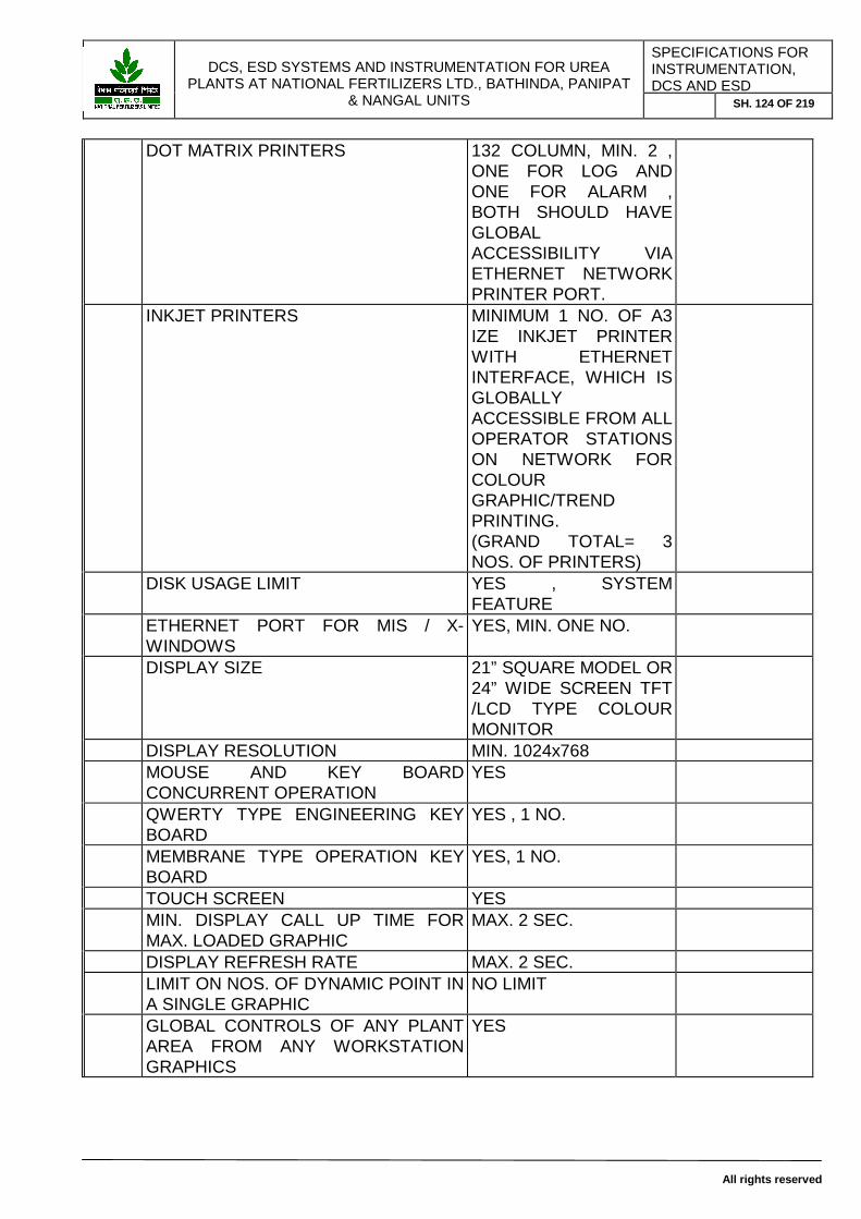
DCS, ESD SYSTEMS AND INSTRUMENTATION FOR UREA
PLANTS AT NATIONAL FERTILIZERS LTD., BATHINDA, PANIPAT & NANGAL UNITS
SPECIFICATIONS FOR INSTRUMENTATION, DCS AND ESD
SH. 124 OF 219
All rights reserved
DOT MATRIX PRINTERS 132 COLUMN, MIN. 2 , ONE FOR LOG AND ONE FOR ALARM , BOTH SHOULD HAVE GLOBAL ACCESSIBILITY VIA ETHERNET NETWORK PRINTER PORT.
INKJET PRINTERS MINIMUM 1 NO. OF A3 IZE INKJET PRINTER WITH ETHERNET INTERFACE, WHICH IS GLOBALLY ACCESSIBLE FROM ALL OPERATOR STATIONS ON NETWORK FOR COLOUR GRAPHIC/TREND PRINTING. (GRAND TOTAL= 3 NOS. OF PRINTERS)
DISK USAGE LIMIT YES , SYSTEM FEATURE
ETHERNET PORT FOR MIS / X-WINDOWS
YES, MIN. ONE NO.
DISPLAY SIZE 21” SQUARE MODEL OR 24” WIDE SCREEN TFT /LCD TYPE COLOUR MONITOR
DISPLAY RESOLUTION MIN. 1024x768 MOUSE AND KEY BOARD
CONCURRENT OPERATION YES
QWERTY TYPE ENGINEERING KEY BOARD
YES , 1 NO.
MEMBRANE TYPE OPERATION KEY BOARD
YES, 1 NO.
TOUCH SCREEN YES MIN. DISPLAY CALL UP TIME FOR
MAX. LOADED GRAPHIC MAX. 2 SEC.
DISPLAY REFRESH RATE MAX. 2 SEC. LIMIT ON NOS. OF DYNAMIC POINT IN
A SINGLE GRAPHIC NO LIMIT
GLOBAL CONTROLS OF ANY PLANT AREA FROM ANY WORKSTATION GRAPHICS
YES

DCS, ESD SYSTEMS AND INSTRUMENTATION FOR UREA
PLANTS AT NATIONAL FERTILIZERS LTD., BATHINDA, PANIPAT & NANGAL UNITS
SPECIFICATIONS FOR INSTRUMENTATION, DCS AND ESD
SH. 125 OF 219
All rights reserved
MASKING, ACCESS LIMIT OF ANY GRAPHICS OR PART THEREOF BY PASSWORD
YES
COMMON STATION FOR OPERATION AND ENGINEERING
YES
ANY OTHER FEATURES * LIMITATIONS NO LIMITATIONS
21 TYPE OF PRINTER SUPPORTED RS232C/USB SERIAL AND CENTRONICS PARALLEL / ETHERNET NETWORK PRINTERS
22 INK JET PRINTERS A3 SIZE INKJET , SERIAL INTERFACERS323C/USB PRINTER , MIN. 300 DPI RESOLUTION, AVAILABLE IN OPEN MARKET MIN. 1 NO. WITH EACH ENGINEERING STATION (TOTAL 2 ENGG. STATION) AND MIN. 1 NO. OF A3 SIZE INKJET PRINTER WITH ETHERNT NETWORK PORT FOR ALL OPERATOR STATIONS, GLOBALLY ACCESSIBLE
23 NOS. OF PRINTERS SUPPORTED MIN. 3 NOS. 1 NO OF ALARM PRINTER( 132 COLUMN DOT MATRIX, ETHERNET PORT), 1 NOS. OF LOG PRINTER (132 COLUMN, ETHERNET PORT) AND 1 NO. OF VIDEO COPIER(A3 INKEJT WITH ETHERNET PORT) ADDITIONALLY THERE SHALL BE A3 SIZE INKJET PRINTER ALONG WITH EACH ENGINEERING STATION AS SPECIFIED

DCS, ESD SYSTEMS AND INSTRUMENTATION FOR UREA
PLANTS AT NATIONAL FERTILIZERS LTD., BATHINDA, PANIPAT & NANGAL UNITS
SPECIFICATIONS FOR INSTRUMENTATION, DCS AND ESD
SH. 126 OF 219
All rights reserved
ABOVE.
24 VIDEO COPIER AND PRINTER GLOBAL ACCESS
YES, MUST VIA ETHERNET PORT AS A NETWORK PRITNER
25 CONTROL STATION TYPE OF PROCESSOR / SPEED 32 BIT MINIMUM
PROCESSOR
USER RAM MIN. 32 MB MIN. CYCLE TIME FOR INPUT
SCANNING 50 M SEC
MIN. CYCLE TIME FOR ALGORITHM EXECUTION
250 MSEC OR BETTER
MIN. CYCLE TIME FOR OUTPUT WRITING
50 MSEC
NORMAL SOFTWARE LOADING 30% SOFTWARE LOADING IN WORST
CONDITION 40%
FUTURE MARGIN AVAILABLE IN SOFTWARE LOAD
50%
REDUNDANCY OFFERED YES , FULL, FAULT TOLERANT, HOT SWAPPABLE
26 DIGITAL INPUT CARD NO. OF CHANNEL MAX. 16 NOS. PER
CARD
INTERROGATION VOLTAGE 24 V DC CHANNEL STATUS LED YES , PER CHANNEL CHANNEL ISOLATION ( CHANNEL TO
CHANNEL AND CHANNEL TO FIELD, ALL CHANNEL SHALL HAVE INDIVIDUAL ISOLATION, NO GROUP ISOLATED CARDS ARE ACCEPTED)
YES, >1000V DC OPTICALLY ISOLATED AS PER IEC:XXX
EARTH FAULT DETECTION CKT. YES, WITH ALARMS OVER CURRENT PROTECTION BY YES , WITH ALARMS LOOP CURRENT MAX. 2 AMP. SURGE WITH STAND CAPACITY YES , AS PER IEC:XXX SCAN RATE 50 MILLI SECOND OR
BETTER
REDUNDANCY NO Testable YES
27 DIGITAL OUTPUT CARD NO. OF CHANNEL MA.X 16 PER CARD

DCS, ESD SYSTEMS AND INSTRUMENTATION FOR UREA
PLANTS AT NATIONAL FERTILIZERS LTD., BATHINDA, PANIPAT & NANGAL UNITS
SPECIFICATIONS FOR INSTRUMENTATION, DCS AND ESD
SH. 127 OF 219
All rights reserved
DRIVING VOLTAGE 24 V D.C. CHANNEL STATUS LED YES, PER CHANNEL CHANNEL ISOLATION ( CHANNEL TO
CHANNEL AND CHANNEL TO FIELD, ALL CHANNEL SHALL HAVE INDIVIDUAL ISOLATION, NO GROUP ISOLATED CARDS ARE ACCEPTED)
OPTICALLY ISOLATED
EARTH FAULT DETECTION CKT. YES, WITH ALARMS OVER CURRENT PROTECTION BY YES, WITH ALARMS MAX LOOP CURRENT 2 AMP. SURGE WITH STAND CAPACITY YES, AS PER IEC:XXX SCAN RATE 50 MILLI SEC OR
BETTER
SHORT CIRCUIT PROTECTION YES, WITH ALARMS PROTECTION AGAINST BACK EMF. YES, AS PER IEC:XXX REDUNDANCY NO Testable YES
28 ANALOG INPUT CARD NO. OF CHANNEL MAX. 16 PER CARD TYPE OF INPUT SHALL BE CAPABLE OF
ACCEPTING 4-20 MA INPUT FROM 2 WIRE AND 4 WIRE TRANSMITTERS, ALSO POWER UP 24 V DC TWO WIRE TRANSMITTER. SHALL HAVE MIN. 250 OHM RESISTOR, SO THAT HART COMMUNICATOR CAN BE PLACED IN PARALLEL WITHOUT DISCONNECTING THE TRANSMITTER LOOP AT ANY TIME
DRIVING VOLTAGE 24 V D.C. CHANNEL STATUS LED YES CHANNEL ISOLATION ( CHANNEL TO
CHANNEL AND CHANNEL TO FIELD, ALL CHANNEL SHALL HAVE INDIVIDUAL ISOLATION, NO GROUP ISOLATED CARDS ARE ACCEPTED)
YES, GALVANICALLY ISOLATED
EARTH FAULT DETECTION CKT. YES,WITH ALARMS OVER CURRENT PROTECTION BY YES,WITH ALARMS MAX LOOP CURRENT 100 mAMP

DCS, ESD SYSTEMS AND INSTRUMENTATION FOR UREA
PLANTS AT NATIONAL FERTILIZERS LTD., BATHINDA, PANIPAT & NANGAL UNITS
SPECIFICATIONS FOR INSTRUMENTATION, DCS AND ESD
SH. 128 OF 219
All rights reserved
SURGE WITH STAND CAPACITY YES, AS PER IEC:XXX SHORT CIRCUIT PROTECTION YES, WITH ALARMS TYPE OF ADC /RESOLUTION MIN. 13 BIT ACCURACY +/- 0.075% SCAN RATE 250 M SEC OR BETTER REDUNDANCY NO Testable YES
28.1 ANALOG OUTPUT CARD NO. OF CHANNEL MAX. 8 PER CARD OUTPUT 4-20 MA DC OUTPUT,
ISOLATED IN MAX. 750 OHM
CHANNEL STATUS LED YES CHANNEL ISOLATION ( CHANNEL TO
CHANNEL AND CHANNEL TO FIELD, ALL CHANNEL SHALL HAVE INDIVIDUAL ISOLATION, NO GROUP ISOLATED CARDS ARE ACCEPTED)
YES, GALVANICALLY ISOLATED
EARTH FAULT DETECTION CKT. YES,WITH ALARMS OVER CURRENT PROTECTION BY YES,WITH ALARMS MAX LOOP CURRENT 30 mAMP SURGE WITH STAND CAPACITY YES, AS PER IEC:XXX SHORT CIRCUIT PROTECTION YES, WITH ALARMS TYPE OF ADC /RESOLUTION MIN. 10 BIT ACCURACY +/- 0.1% SCAN RATE 1 SEC OR BETTER REDUNDANCY NO Testable YES
29 THERMOCOUPLE INPUT CARDS MAX. NO. OF CHANNEL PER CARD 16 NOS. TYPE OF INPUT THERMOCOUPLES E,J,K,R,S,B,T, ETC.. CALIBRATION OF CARD AS PER AS PER ANSI:MC96.1 CALIB. FREQ.. REQUIRED MIN. CHANNEL ISOLATION ( CHANNEL TO
CHANNEL AND CHANNEL TO FIELD, ALL CHANNEL SHALL HAVE INDIVIDUAL ISOLATION, NO GROUP ISOLATED CARDS ARE ACCEPTED)
YES, MIN 1000 VAC, GALVANICALY ISOLATED
ACCURACY +/- 0.1’C ADC RESOLUTION MIN. 13 BIT MIX. TYPE CONFIGURATION (i.e.
DIFF. TYPES OF T/C FOR DIFF. CHANNEL OF SINGLE CARD)
YES
INPUT ISOLATION GALAVANICALLY ISOLATED

DCS, ESD SYSTEMS AND INSTRUMENTATION FOR UREA
PLANTS AT NATIONAL FERTILIZERS LTD., BATHINDA, PANIPAT & NANGAL UNITS
SPECIFICATIONS FOR INSTRUMENTATION, DCS AND ESD
SH. 129 OF 219
All rights reserved
GROUNDED/UNGROUNDED INPUTS YES BURN OUT FEATURE YES , PER CHANNEL STATUS LED FOR IND. CHANNEL YES SCAN RATE 1 SECOND OR BETTER REDUNDANCY NO
30 RTD INPUT CARDS MAX. NO. OF CHANNEL PER CARD 16 NOS. TYPE OF INPUT RTD SENSORS PT100 , 3 WIRE AND 4
WIRE AND OTHERS
CALIBRATION OF CARD AS PER AS PER DIN:43760/IEC529
CALIB. FREQ.. REQUIRED MIN. CHANNEL ISOLATION ( CHANNEL TO
CHANNEL AND CHANNEL TO FIELD, ALL CHANNEL SHALL HAVE INDIVIDUAL ISOLATION, NO GROUP ISOLATED CARDS ARE ACCEPTED)
YES, MIN. 1000 V AC
ACCURACY +/- 0.1 ‘C ADC RESOLUTION MIN. 13 BIT MIX. TYPE CONFIGURATION (i.e.
DIFF. TYPES OF RTD FOR DIFF. CHANNEL OF SINGLE CARD)
YES
INPUT ISOLATION GALVANICALLY ISOLATED
3 WIRE AND 4 WIRE RTD INPUTS YES SHORT CIRCUIT PROTECTION YES , WITH ALARMS OPEN CIRCUIT PROTECTION YES, WITH ALARMS STATUS LED FOR IND. CHANNEL YES, WITH ALARMS EARTH FAULT DETECTION CKT. YES, WITH ALARMS OVER CURRENT PROTECTION YES, WITH ALARMS SCAN RATE 1 SECOND OR BETTER REDUNDANCY NO
31 CONTROLLER SYSTEM CONTROLLER CAPACITY
(An array of small controllers clubbed together to meet this specification will not be acceptable)
MIN. 100 CLOSED LOOPS AT 250 MILLI SECONDS, TOTAL I/O COUNTS SUPPORTED BY SINGLE CONTROL PROCESSOR SHALL BE MIN. 1000 NOS.CONTROLLER SHOULD BE CAPABLE OF MINIMUM EXECUTION TIME OF 50 MILLI SECONDS.

DCS, ESD SYSTEMS AND INSTRUMENTATION FOR UREA
PLANTS AT NATIONAL FERTILIZERS LTD., BATHINDA, PANIPAT & NANGAL UNITS
SPECIFICATIONS FOR INSTRUMENTATION, DCS AND ESD
SH. 130 OF 219
All rights reserved
CONTROL ALGORITHMS RUNNING IN MAIN CONTROL PROCESSOR
AUTO TUNE AS STANDARD FEATURE YES , FOR ALL LOOPS BY DEFAULT
MAX. ALGORITHM EXECUTION TIME 250 MSEC MIN. INPUT AND OUTPUT POLL TIME 50 SECOND OR
BETTER
MAX. LOAD FOR PRESENT APPLICATION
30%
FUTURE MARGIN IN SOFTWARE LOAD
50%
CONTROL PROCESSOR IS CAPABLE OF RUNNING THIRD PARTY PACKAGE
YES , FOR ALL LOOPS
SUPPORT FOR ALL STD. ALGORITHMS
YES , FOR ALL STD. TYPES AS SPECIFIED IN ENQ. SPECS , INCLUDING SEQUENTILA,BATCH AND CONTINUOS CONTROL AND MATHS, LOGIC FUNCITON
ON LINE MODIFICATION /ADDITION AND DELETION OF ANY LOOP OR LOOP TAG
YES
PEER TO PEER COMMUNICATION / LIMITATIONS
YES WITHOUT ANY TAG LIMIT
PEER TO PEER COMMUNICATION LOAD
MIN.
SOFTWARE PARAMETER INTERCONNECTION LIMIT
NO
DATA RETENTION TIME IN RAM MIN. 1000 HRS. SELF BOOTABLE YES CHECKPOINT FACILITY WITH AUTO
SCHEDULING YES , AT REGULAR USER CONFIGURED INTERVAL
CONTROL CONFIGURATION FACILITIES
GUI BASED , SUPPORTED BY MOUSE AND KEY BOARD WITH ALL TYPES OF EDITING FEATURES AND ON LINE CONTEXT SENSITIVE HELP
AUTOMATIC UPLOAD OF ANY RUN TIME CHANGES MADE IN CONTROL
YES

DCS, ESD SYSTEMS AND INSTRUMENTATION FOR UREA
PLANTS AT NATIONAL FERTILIZERS LTD., BATHINDA, PANIPAT & NANGAL UNITS
SPECIFICATIONS FOR INSTRUMENTATION, DCS AND ESD
SH. 131 OF 219
All rights reserved
DATABASE
DOWNLOAD / BOOT TIME MIN. SECURITY WITH DIFF. LEVEL OF
PASSWORD FOR DIFF. CATEGORY OF OPERATION
REDUNDANCY YES, 100% REDUNDANT WITH FAULT TOLERANT FEATURES, HOTSWAPPABLE
32 REDUNDANCY OFFERED AT I/O NO CPU YES (100%
REDUNDANT WITH FAULT TOLERANT FEATURE WITH HOT SWAPPABLE CONFIGURATION)
INTERNAL BUSES YES (100% REDUNDANT WITH FAULT TOLERANT FEATURE WITH HOT SWAPPABLE CONFIGURATION)
COMM. MODULE YES (100% REDUNDANT WITH FAULT TOLERANT FEATURE WITH HOT SWAPPABLE CONFIGURATION)
MAIN NODE BUS YES (100% REDUNDANT WITH FAULT TOLERANT FEATURE WITH HOT SWAPPABLE CONFIGURATION)
POWER SUPPLY MODULES OF ALL SYSTEM CARDS/MODULES/NODES
YES (100% REDUNDANT WITH FAULT TOLERANT FEATURE WITH HOT SWAPPABLE CONFIGURATION)
CONTROLLERS YES (100% REDUNDANT WITH

DCS, ESD SYSTEMS AND INSTRUMENTATION FOR UREA
PLANTS AT NATIONAL FERTILIZERS LTD., BATHINDA, PANIPAT & NANGAL UNITS
SPECIFICATIONS FOR INSTRUMENTATION, DCS AND ESD
SH. 132 OF 219
All rights reserved
FAULT TOLERANT FEATURE WITH HOT SWAPPABLE CONFIGURATION)
GATEWAYS YES (100% REDUNDANT WITH FAULT TOLERANT FEATURE WITH HOT SWAPPABLE CONFIGURATION)
WORK STATIONS YES HDD YES (100%
REDUNDANT WITH FAULT TOLERANT FEATURE WITH HOT SWAPPABLE CONFIGURATION)
PRINTER BACK UP PORTS YES, INCASE OF FAILURE OF LOG OR ALARM PRINTER, THE OTHER WORKING PRINTER SHOULD AUTOMATICALLY RESUME THE ROLE OF THE FAILED PRINTER
33 COMMUNICATION TO PLC
PROTOCOL MODBUS-RTU INTERFACE 2 WIRE RS485 MAX. LENGTH OF INTERFACE CABLE
PERMITTED MIN. 1200 MTR.
NO. OF PORTS ON SINGLE MODULE MULTIPLE MAX. BAUD RATES REQUIRED. MIN. 19200 MODULE REDUNDANCY YES BUS REDUNDANCY YES PARAMETER/SEC MAX. 1 SECOND WITH
ANY TYPE OF MIX. CONFIGURATION
TOTAL CAPACITY COMMUNICATION ESTABLISHED
WITH GIVE THE NAMES OF ESD SYSTEMS FOR WHICH DCS VENDOR HAS ESTABLISHED COMMUNICAITONS SO FAR
TOTAL LOADING FOR CONFIGURED <30%

DCS, ESD SYSTEMS AND INSTRUMENTATION FOR UREA
PLANTS AT NATIONAL FERTILIZERS LTD., BATHINDA, PANIPAT & NANGAL UNITS
SPECIFICATIONS FOR INSTRUMENTATION, DCS AND ESD
SH. 133 OF 219
All rights reserved
TAGS FUTURE MARGIN >50% LIMITATIONS NO OTHER FEATURES
34 COMMUNICATION BETWEEN DCS AND PLC
DCS BIDDER TO CO-ORDINATE WITH PLC BIDDER FOR ESTABLISHING COMMUNICATION BETWEEN DCS AND PLC AND CONFIGURE REQUIRED INTERFACE / TAGS / DISPLAYS /DATABASE ETC.
35 WRITE BACK TO PLC FROM DCS YES , WITH SECURITY FEATURES. HOWEVER THIS FEATURE SHALL NOT BE USED.
36 DCS CLOCK TIME SYNCHRONIZATION METHOD
WITH PLC YES
STABILITY OF CLOCK +/- 1 SEC OND PER DAY
TEMPERATURE EFFECT MIN. 37 ALARMS SEQUENCE
MAX. NOS. OF PROCESS ALARMS MIN. 10,000 MAX. NOS. OF SYSTEM ALARMS MIN. 5,000 SEGREGATION OF PROCESS AND
SYSTEM ALARMS YES WITH DIFF. COLOUR/PRIORITY/HOOTER SOUNDS
APPEARANCE OF ALARMS IN SEQUENTIAL MANNER
YES WITH 1 SECOND TIME STAMP
TIME AND DATE STAMPING WITH 1 SEC. RESOLUTION
YES
PRINT OUT OF CURRENT AND HSITORIZED ALARMS
YES
FULLY CONFIGURABLE OR STD. ALARM DISPLAYS
YES, WITH WINDOWS TYPE FEATURE WITH ALL GUI FACILITIES
TOTAL NOS. OF ALARM PAGES MIN. 25 MAX. NOS. OF ALRMS PER PAGE MIN. 20 TOTAL NOS. OF SYSTEM ALARM
PAGES MIN. 25
MAX. NOS. OF ALARMS PER PAGE MIN. 10

DCS, ESD SYSTEMS AND INSTRUMENTATION FOR UREA
PLANTS AT NATIONAL FERTILIZERS LTD., BATHINDA, PANIPAT & NANGAL UNITS
SPECIFICATIONS FOR INSTRUMENTATION, DCS AND ESD
SH. 134 OF 219
All rights reserved
TOTAL NOS. OF PROCESS ALARMS IN RECENT ALARM LIST
MIN. LAST 500 NOS. OF ALARMS
TOTAL NOS. OF SYSTEM ALARMS IN RECENT ALARM LIST
MIN. LAST 250 NOS. OF ALARMS
LAST IN FIRST OUT PATTERN IN PROCESS AND SYSTEM ALARM STORAGE IN REAL TIME AND HISTORY.
YES
SORTING OF ALARMS BASED ON TAG , PRIORITY, OCCURANCE, ETC.
YES
MULTIPLE ACKNOLEDGEMENT OF ALARMS WITH SINGLE KEY STROKE
YES
GLOBAL ACKNOWLEDGEMENT OF ALARMS
YES , FROM ANY WORK STATION
DIFF. PRIORITY AND TONES YES , MIN. 4 PRIORITY LEVELS WITH DIFF. TONE FOR PROCESS AND SYSTEM ALARM
COLOUR STATE CHANGE IN ALALARM OCCURANCE AND ACKNOWLEDGEMENT
YES , MIN. 2 STATE COLOUR CHANGES
ALARM ENABLING AND DISABLING IN A LOOP RUN TIME
YES
ALARM VALUE CHANGES IN RUN TIME
YES
PASSWORD PROTECTION FOR ABOVE CHANGES
YES
LATCHED TYPE ALRMS FOR PROCESS AND SYSTEM
YES, WITHOUT OPERATOR INTRVENTION, IT SHOULD NOT DISAPPEAR FROM ALARM DATABASE
38 OPERATOR ACTION JOURNAL WITH TIME DATE STAMP
YES, SEQUENTIAL RECORING
39 MAX. NOS. OF CHANGES RECORDABLE
MIN. 10,000
40 GRAPHICAL USER INTERFACE GRAPHIC BUILDING WITH MOUSE
AND KEY BOARD YES
STANDARD GUI BASED WINDOWING GRAPHICS
YES , LIKE X-WINDOWS, OPEN LOOK, MOTIF OR WINDOWS NT GUI
TOTAL NOS. OF COLOURS SUPPORTED
MIN. 16 MILLION

DCS, ESD SYSTEMS AND INSTRUMENTATION FOR UREA
PLANTS AT NATIONAL FERTILIZERS LTD., BATHINDA, PANIPAT & NANGAL UNITS
SPECIFICATIONS FOR INSTRUMENTATION, DCS AND ESD
SH. 135 OF 219
All rights reserved
TOTAL NOS. OF DIFF. SIZE OF FONTS SUPPORTED
MIN. 16
TOTAL NOS. OF DIFF. SIZE OF LINE THICKENS SUPPORTED
MIN. 4
DRAG AND DROP WITH EDIT, COPY CUT, PASTE FEATURE
YES
LIBRARY FACILITIES FOR SYMBOLS YES, AS PER ISA S5.X/IEC1131
IMPORT / EXPORT OF GRAPHICS IN OTHER GRAPHICS
YES
STANDARD SYMBOL LIBRARY AS PER ISA
YES
FREELY SIZABLE WINDOWING FEATURE
YES
MAX. NO. OF WINDOWS ON A SIGNLE OPERATOR STATION
MIN. 4
OVERLAYING FEATURE YES MAX. NO. OF OVERLAYS ON A
SINGLE GRAPHIC NO LIMIT
MAX.. NO. OF ALL TYPES OF DYNAMIC POINTS PER DISPLAY
NO LIMIT
MAX. NOS. OF USER CREATED GRAPHICS
NO LIMIT
MAX. FILE SIZE LIMIT OF A GRAPHIC NO LIMIT STANDARD GRAPHICS LIKE SYSTEM
DIAGNOSTICS ETC. YES
ON LINE CONTEXT SENSITIVE HELP FOR GRAPHIC BUILDING
YES
ANY PROGRAMMING LANGUAGE SUPPORT BY GRAPHICS
YES
STARTING OF USER PROGRAM FROM GRAPHIC PANLE / SOFT TARGETS
YES
CUSTOMIZED , COMPLEX GRAPHICS FOR MANIPULATING CONTROL STRATEGIES BY OPERATOR
YES
GLOBAL CHANGES FOR A GRAPHICS AT SINGLE LOCATION WITH SINGLE COMMAND
YES, WITHOUT ANY MANUAL COPY/PASTE COMMANDS TO OTHER OPERATOR STATIONS
MEMORY RESIDENT GRAPHICS AT WORKSTATION
MAX
41 TRENDS REAL TIME TRENDS YES HISTORIAN TRENDS YES, MIN. 2000 TAGS
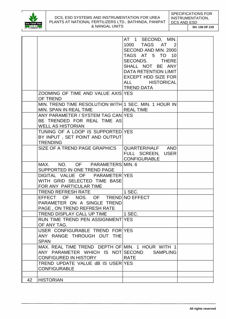
DCS, ESD SYSTEMS AND INSTRUMENTATION FOR UREA
PLANTS AT NATIONAL FERTILIZERS LTD., BATHINDA, PANIPAT & NANGAL UNITS
SPECIFICATIONS FOR INSTRUMENTATION, DCS AND ESD
SH. 136 OF 219
All rights reserved
AT 1 SECOND, MIN. 1000 TAGS AT 2 SECOND AND MIN. 2000 TAGS AT 5 TO 10 SECONDS. THERE SHALL NOT BE ANY DATA RETENTION LIMIT EXCEPT HDD SIZE FOR ALL HISTORICAL TREND DATA
ZOOMING OF TIME AND VALUE AXIS OF TREND
YES
MIN. TREND TIME RESOLUTION WITH MIN. SPAN IN REAL TIME
1 SEC. MIN. 1 HOUR IN REAL TIME
ANY PARAMETER / SYSTEM TAG CAN BE TRENDED FOR REAL TIME AS WELL AS HISTORIAN
YES
TUNING OF A LOOP IS SUPPORTED BY INPUT , SET POINT AND OUTPUT TRENDING
YES
SIZE OF A TREND PAGE GRAPHICS QUARTER/HALF AND FULL SCREEN, USER CONFIGURABLE
MAX. NO. OF PARAMETERS SUPPORTED IN ONE TREND PAGE
MIN. 6
DIGITAL VALUE OF PARAMETER WITH GRID SELECTED TIME BASE FOR ANY PARTICULAR TIME
YES
TREND REFRESH RATE 1 SEC. EFFECT OF NOS. OF TREND
PARAMETER ON A SINGLE TREND PAGE , ON TREND REFRESH RATE
NO EFFECT
TREND DISPLAY CALL UP TIME 1 SEC. RUN TIME TREND PEN ASSIGNMENT
OF ANY TAG. YES
USER CONFIGURABLE TREND FOR ANY RANGE THROUGH OUT THE SPAN
YES
MAX. REAL TIME TREND DEPTH OF ANY PARAMETER WHICH IS NOT CONFIGURED IN HISTORY
MIN. 1 HOUR WITH 1 SECOND SAMPLING RATE
TREND UPDATE VALUE dB IS USER CONFIGURABLE
YES
42 HISTORIAN

DCS, ESD SYSTEMS AND INSTRUMENTATION FOR UREA
PLANTS AT NATIONAL FERTILIZERS LTD., BATHINDA, PANIPAT & NANGAL UNITS
SPECIFICATIONS FOR INSTRUMENTATION, DCS AND ESD
SH. 137 OF 219
All rights reserved
TOTAL NO. OF HISTORIAN POINTS SUPPORTED BY THE SYSTEM
SYSTEM TAG
MIN. SCAN TIME PER POINT 1 SEC. FOR MIN. 200O TAGS, 2 SECONDS FOR MIN. 1000 TAGS, 5 TO 10 SECONDS FOR MIN. 1000 TAGS . TOTAL HISTORIAN SIZE SHALL BE MIN. 5000
AVERAGING , MIN. MAX. AND OTHER MATH FUNCTIONALITY AVAILABILITY
YES
PRESENT HISTORIAN LOAD 40% FUTURE MARGIN IN HISTORY 60% ANY ATTRIBUTE OF ANY
PARAMETER (TAG) CAN BE HISTORIZED, LIKE PV ,MV,SV,ALARM FLAG, DIGITAL INPUT,OUTPUT,BAD VALUE FLAG,ETC..
YES
RETENTION TIME FOR ALL THE POINTS AT 1 SEC.
NO TIME LIMIT, EXCEPT THE HDD SIZE
RUN TIME ADDITION OR DELETION OF ANY TAG IN HISTOYR
YES
EFFECT OF SYSTEM TIME ADJUSTMENT , BACK AND FORHT ON HSITORIAN DATA
NO LOSS OF DATA
2ND HDD REQUIREMENT ON ALL THE STATIONS, WHERE HISTORIAN TREND, LONG TERM LOG/REPORT, ETC. ARE STORED, WILL BE QUIPPED WITH 500 GB RAID-I HDD WITH HOT SWAPPABLE FEATURE
ANY OTHER LIMITATION NO LIMIT
43 REPORTS / LOGS MAX. POINTS/TAGS PER REPORTS NO LIMIT MAX. NO. OF USER CONFIGURED
REPORTS NO LIMIT
TYPE OF REPORTS SNAP SHOT, HOURLY,SHIFT,DAILY,WEEKLY, MONTHLY, AND USER SCHEDULED INTERVAL ,ETC.
ON DEMAND REPORTS GENERATION AND PRINTOUT AT ANY
YES

DCS, ESD SYSTEMS AND INSTRUMENTATION FOR UREA
PLANTS AT NATIONAL FERTILIZERS LTD., BATHINDA, PANIPAT & NANGAL UNITS
SPECIFICATIONS FOR INSTRUMENTATION, DCS AND ESD
SH. 138 OF 219
All rights reserved
TIME FOR ANY TYPE OF REPORTS
REPORT DEVELOPING TOOLS MENU DRIVEN , GUI BASED
HISTORY/ REAL TIME REPORT SUPPORT
YES
MATH. CAPACITY IN REPORT WRITER
YES
REPORT RETENTION TIME NO LIMIT EXCEPT HDD SIZE
REPORT ARCHIVE ON DAT YES , NO LIMIT, AUTOMATIC
REPORT ARCHIVE ON 3.5" FLOPPY YES , AUTOMATIC REPORT FILE FORMAT MICROSOFT EXCEL
LATEST VERSION. ALL OPERATOR AND ENGINEERING STATIONS SHALL BE EQUIPPED WITH MS OFFICE LICENSE COPY.
CUSTOMIZED REPORT YES CUSTOMIZED REPORT SCHEDULE ,
RUNNING AT MIN. OF 1 MIN. INTERVAL
YES
44 SYSTEM DIAGNOSTICS I/O MODULE YES , UPTO IND.
CHANNEL STATUS
CONTROLLER YES , INCLUDES ALL MODULE, COMPRISING OF CONTROLLER SUB SYSTEM
MAIN FILE SERVER YES, INCLUDING ALL LOCAL PERIPHERALS
ALL PERIPHERALS YES, ALL GLOBAL PERIPHERALS
ANY TYPE OF MINOR SOFTWARE AND HARDWARE ERROR
YES
ROUTINE SYSTEM DIAGNOSTICS YES ANY INTERNAL OR EXTERNAL COMM.
ERROR, INCLDING BUS FAILURES YES
MAJOR HARDWARE FAILURE YES MAJOR SOFTWARE FAILURE YES SYSTEM REDUNDANT COMPONENT
CHANGEOVER YES

DCS, ESD SYSTEMS AND INSTRUMENTATION FOR UREA
PLANTS AT NATIONAL FERTILIZERS LTD., BATHINDA, PANIPAT & NANGAL UNITS
SPECIFICATIONS FOR INSTRUMENTATION, DCS AND ESD
SH. 139 OF 219
All rights reserved
ON LINE HELP FOR ALL TYPES OF FAILURES
YES
SYSTEM MODULE DYNAMIC LOAD INDICATIONS
YES
ANY OTHER TYPE OF DIAGNOSTIC OFFERED
45 SYSTEM SECURITY LEVEL LEVEL-1 OPERATOR LEVEL-2 SUPERVISOR LEVEL-3 ENGINEER LEVEL4 SYS. ADMINISTRATOR
46 SYSTEM BATTERY BACK UP TIME FOR DATA HOLD
MIN. 72 HRS.
47 COMPLETE SYSTEM COLD START UP TIME
MIN.
48 SYSTEM SELF BOOTABLE YES , WITHOUT ANY USER INTERVENTION WITH ALL DEFAULT PERSONALITIES, IMAGES AND LAST CHECKPOINTED DATABASE
49 INTELLIGENT I/O YES 50 UNIVERSAL I/O BONUS 51 I/O SIGNAL SEGREGATION
I/O TYPE YES REQUIRED FROM MARSHALLING PANEL LEVEL AND DCS SYSTEM HARDWARE PANEL LEVEL
PLANT UNIT AREA YES REQUIRED FROM MARSHALLING PANEL LEVEL AND DCS SYSTEM HARDWARE PANEL LEVEL
52 OPTIONAL SOFTWARE QUOTED AS AGAINST OUR STD. SOULUTION REQUIREMENT
NOT ALLOWED
53 OPTIONAL SOFTWARE QUOTED AS EXTRA FEATURE /SYSTEM ENHENCEMENT, WHICH ARE NOT INCLUDED IN ENQ. SPECS.
BIDDER TO HIGHLIGHT ALL SUCH FEATURES
54 SPARES QUOTED FOR TWO YEARS TROUBLE FREE OPERATION OF THE
YES, WTH UNIT PRICE

DCS, ESD SYSTEMS AND INSTRUMENTATION FOR UREA
PLANTS AT NATIONAL FERTILIZERS LTD., BATHINDA, PANIPAT & NANGAL UNITS
SPECIFICATIONS FOR INSTRUMENTATION, DCS AND ESD
SH. 140 OF 219
All rights reserved
COMPLETE SYSTEM
55 NOS. OF CABINETS SUFFICIENT TO ACCOMMODATE ALL H/W , AS SPECIFIED. MARSHALLING/PDB/SYSTEM CABINET SHALL BE AS PER SPECIFICATIONS AND QTY SHALL BE AS PER OWNERS GUIDELINES/REQUIREMENT SPECIFIED IN THIS COMPLETE ENQ. DOCUMENT
56 MAKE / MODEL OF CABINET RITTAL / MODEL: 4108 WITH ALL OTHER ACCESSORIES AS MENTIONED IN ENQ. SPECS 1200MM(W) X 800MM(D)X 2100MM(H), RAL 7032 COLOUR SHED, ALL IDENTICAL
57 INTERNAL WIRING OF PANELS DIGITAL INPUTS WIRING SIZE
/COLOUR 1.0 SQ. MM MULTI STRAND , SILVER COATED , TEFLON INSULATED/STD
DIGITAL OUTPUTS WIRING SIZE /COLOUR
1.0 SQ. MM MULTI STRAND , SILVER COATED , TEFLON INSULATED/STD
ANALOG INPUT WIRING SIZE / COLOUR
0.75 SQ. MM MULTI STRAND , SILVER COATED , TEFLON INSULATED/STD
110 V AC SUPPLY WIRING SIZE / COLOUR
MIN. SIZE SHALL BE 2.5 SQ. MM , MULTISTREND, COPPER WIRE/STD
24 V DC SUPPLY WIRING SIZE / COLOUR
MIN. SIZE SHALL BE 2.5 SQ. MM , MULTISTRAND, COPPER WIRE/STD
58 INTERPOSING RELAYS

DCS, ESD SYSTEMS AND INSTRUMENTATION FOR UREA
PLANTS AT NATIONAL FERTILIZERS LTD., BATHINDA, PANIPAT & NANGAL UNITS
SPECIFICATIONS FOR INSTRUMENTATION, DCS AND ESD
SH. 141 OF 219
All rights reserved
MAKE AND MODEL OMRON MAKE, 24 V DC, SOCKET MOUNT, 4 NO/NC WITH LED INDICATION FOR COIL
SUPPLY VOLTAGE 24 V D.C. CONTACT RATING 240 V A.C. / 5 AMP INBUILT DIODE/LED YES NOS. OF CONTACTS 4 NO/NC BY-PASSING ARRANGEMENT NO MOUNTING ARRANGEMENT PLUG-IN TYPE /
SOCKET DIN RAIL MOUNTED
OTHER LIMITATIONS NO LIMITATIONS 59 TYPE OF TERMINATIONS
ANALOG INPUT 0.5 TO 4.0 SQ. M.M. WIRE SUITABLE, MELAMINE MATERIAL OF WAGO MAKE, SCREW LESS, SIDE/SIDE ENTRY TYPE
DIGITAL INPUT FUSED TERMINALS 0.5 TO 4.0 SQ. M.M. WIRE SUITABLE MELAMINE MATERIAL OF WAGO MAKE, SCREW LESS, SIDE/SIDE ENTRY TYPE
DIGITAL OUTPUT FUSED TERMINALS 0.5 TO 4.0 SQ. M.M. WIRE SUITABLE MELAMINE MATERIAL OF WAGO MAKE, SCREW LESS, SIDE/SIDE ENTRY TYPE
60 POWER SUPPLY WITH BUSBAR SIZING CALCULATION
YES
61 TAGGING / FERRULING / COLOUR CODING AS PER REQUIREMENT
YES, AS PER ENQ. SPECS
62 POWER SUPPLY REQUIREMENT 110 V A.C. +/- 10% , AT 50 Hz +/- 6%
63 SYSTEM IS CAPABLE OF ACCEPTING DUAL POWER SUPPLY SOURCE AS PRIMARY AND SECONDARY
YES, ALL THE NODES, MODULES OF SYSTEM SHALL BE CAPABLE OF ACCEPTING DUAL REDUNDANT 110 V AC

DCS, ESD SYSTEMS AND INSTRUMENTATION FOR UREA
PLANTS AT NATIONAL FERTILIZERS LTD., BATHINDA, PANIPAT & NANGAL UNITS
SPECIFICATIONS FOR INSTRUMENTATION, DCS AND ESD
SH. 142 OF 219
All rights reserved
OR DUAL REDUNDANT 24 V DC POWER SUPPLY
64 TYPE OF POWER SUPPLY ( EXTERNAL)
110 V A.C. +/- 10% , AT 50 Hz +/- 6% AND 24 V DC, DUAL REDUNDANT BULK POWER SUPPLY, FLOATING TYPE ( PROVIDED BY BIDDER WITH THE HELP OF 110 V AC INPUT)
FRONT PANEL DIGITAL INDICATIONS YES, FOR VOLTAGE AND CURRENT IN DIGITAL WITH TWO DECIMAL POINT
FRONT PANEL CURRENT AND VOLTAGE ADJUSTMENT
YES
PARALLELING WITH DIODE CKT. YES COOLING FANS WITH STOP ALARM YES OTHER FEATURES CAPACITY>130% LIMITATIONS NO LIMITATIONS
65 PDB WITH ALL DULY RATED COMPONENT OFFERED
AS SPECIFIED IN ENQ. SPECS.
FRONT PANEL INDICATION YES, FOR DIGITAL INDICATION OF VOLTAGE ONLY
FUSE -COORDINATION AND CALCULATIONS
YES
ANY LIMITATIONS NO 66 LOOPING FOR ANY SUPPLY
110 V AC NOT ALLOWED 24 V DC NOT ALLOWED
67 POWER CONSUMPTION MIN. 68 POWER CONSUMPTION
CALCULATIONS ATTACHED YES
69 HEAT DISSIPATION LOAD MIN. 70 HEAT DISSIPATION LOAD
CALCULATIONS ATTACHED YES
71 MAX. AMBIENT TEMP. ALLOWED 55 ' C 72 POWER SUPPLY REDUNDANCY YES
110 VAC FOR SYSTEM POWER YES , 100% 24 V DC FOR INTERPOSING RELAYS YES, 100%
73 POWER INTERRUPTION TOLERANCE OF SYSTEM
>100 MSEC
74 FAT AGREEMENT

DCS, ESD SYSTEMS AND INSTRUMENTATION FOR UREA
PLANTS AT NATIONAL FERTILIZERS LTD., BATHINDA, PANIPAT & NANGAL UNITS
SPECIFICATIONS FOR INSTRUMENTATION, DCS AND ESD
SH. 143 OF 219
All rights reserved
75 SAT AGREEMENT 76 DOCUMENTATION AS PER
REQUIREMENT
HARD COPIES 5 NOS. OF HARD COPIES FOR ALL CATALOGS, DOCUMENTS, LOOPSHEETS, DRAWINGS, DOCUMENTS, ETC.
SOFT COPIES IN SPECIFIED FORMAT
2 NOS. OF SOFT COPIES OF ABOVE ALL DOCUMENTS IN EDITABLE SOFTWARE FORM IN MICROSOFT EXCEL AND AUTOCADON ON CD-ROM
77 BIDDER'S RESPONSIBILITY FOR ERECTION AND COMMISSIONING
AS MENTIONED IN ENQ. SPECS
78 DELIVERY PERIOD MIN. 79 WARRANTY PERIOD / LIMITATIONS 12 MONTHS FROM SAT
(SITE ACCEPTANCE TEST)OF THE SYSTEM.
80 UNIT RATES OFFERED YES 81 TRAINING AS MENTIONED IN
ENQ. SPECS
*To be specified by the bidder.
DCS, ESD SYSTEMS AND INSTRUMENTATION FOR UREA
PLANTS AT NATIONAL FERTILIZERS LTD., BATHINDA, PANIPAT & NANGAL UNITS
SPECIFICATIONS FOR INSTRUMENTATION, DCS AND ESD
SH. 144 OF 219
All rights reserved
SECTION-IV
EMERGENCY SHUTDOWN SYSTEM (ESD) SPECIFICATIONS

DCS, ESD SYSTEMS AND INSTRUMENTATION FOR UREA
PLANTS AT NATIONAL FERTILIZERS LTD., BATHINDA, PANIPAT & NANGAL UNITS
SPECIFICATIONS FOR INSTRUMENTATION, DCS AND ESD
SH. 145 OF 219
All rights reserved
PART-I
INDEX
SR. NO.
TOPIC
1.0 GENERAL REQUIREMENT/DESIGN CRITERIA 2.0 BIDDER'S RESPONSIBILITY 3.0 SCOPE OF VALIDITY 3.1 STANDARDS & SPECIFICATIONS 3.2 REQUIREMENTS OF SYSTEM CONFIGURATION &
HARDWARE ESD SYSTEM 4.0 OPERATIONS AND FUNCTIONS 4.1 OVERVIEW 4.2 SYSTEM STATUS 4.3 AUXILIARY HARDWIRED CONSOLE 4.4 TRANSIT FAULT ALARM 4.5 MANUAL RESET 4.6 SEQUENCE OF EVENT RECORDER 5.0 ESD SYSTEM SOFTWARE 5.1 SECURITY 5.2 PROGRAMMING 5.3 SOFTWARE UTILITIES 5.4 CONFIGURATION 5.5 DIAGNOSTICS 6.0 CABINETS / PANELS 6.1 MARSHALLING / AUX CABINETS 6.2 SYSTEM HARDWARE CABINETS 6.3 PDB CABINETS 6.4 INTERCONNECTION CABLES 6.5 VENTILATON 6.6 WIRE TERMINATION 6.7 INTERNAL WIRING 6.8 POWER SUPPLY 6.9 GROUND/EARTHING 7.0 NAME AND TAG PLATES 8.0 SYSTEM AVAILABILITY 9.0 TRAINING 10.0 INSPECTION TESTING 11.0 INSTALLATION AND PRE-COMMISSIONING 12.0 FAT 13.0 DOCUMENTS AND DRAWINGS 13.1 AS-BUILT DRAWINGS 14.0 INFORMATION REQUIRED WITH THE BID

DCS, ESD SYSTEMS AND INSTRUMENTATION FOR UREA
PLANTS AT NATIONAL FERTILIZERS LTD., BATHINDA, PANIPAT & NANGAL UNITS
SPECIFICATIONS FOR INSTRUMENTATION, DCS AND ESD
SH. 146 OF 219
All rights reserved
GENERAL PROJECT INFORMATION
A. OWNER : NATIONAL FERTILIZERS LTD
CONTACT PERSON : CONTACT PERSON
(COMMERCIAL) : CHIEF MANAGER (MATERIALS)
NATIONAL FERTILIZERS LIMITED SIBIAN ROAD BATHINDA- 151003
D. NAME OF PROJECT : INSTRUMENTATION, DCS AND ESD
SYSTEMS FOR UREA PLANTS AT NFL BATHINDA, PANIPAT AND NANGAL UNITS.
E. SITE ADDRESS : NATIONAL FERTILIZERS LTD.
BATHINDA UNIT, BATHINDA-(PUNJAB) 151003 NATIONAL FERTILIZERS LTD. PANIPAT UNIT, PANIPAT (HARYANA) NATIONAL FERTILIZERS LTD. NANGAL UNIT, NANGAL (PUNJAB)

DCS, ESD SYSTEMS AND INSTRUMENTATION FOR UREA
PLANTS AT NATIONAL FERTILIZERS LTD., BATHINDA, PANIPAT & NANGAL UNITS
SPECIFICATIONS FOR INSTRUMENTATION, DCS AND ESD
SH. 147 OF 219
All rights reserved
SECRECY AGREEMENT
All rights relating to this technical specification and document, generated during engineering of the system, are reserved by OWNER. No information technical or otherwise, in part or full shall be divulged, disclosed or re-used by the BIDDER to anyone without the explicit written permission of OWNER.

DCS, ESD SYSTEMS AND INSTRUMENTATION FOR UREA
PLANTS AT NATIONAL FERTILIZERS LTD., BATHINDA, PANIPAT & NANGAL UNITS
SPECIFICATIONS FOR INSTRUMENTATION, DCS AND ESD
SH. 148 OF 219
All rights reserved
1.0 General Requirement/Design Criteria
1.1 Part-I covers the general requirements of Emergency shutdown system (ESD) like scope of work of selected BIDDER, general hardware & software requirements, documentation, training requirements etc.
Part-II covers specific project requirements of the system.
Scope The offered system shall be QMR Safety ESD (PLC) System and TUV certified for Safety Class-6 (AK6) SIL3. Though the specifications of ESD in this and specification of DCS specified in relevant section are different, all Common items like cabinets, bought out items like marshalling panels, system hardware panels, fuses; terminal blocks, etc. shall be identical. Documentation shall be maintained uniform. Material, wiring and ferruling philosophy shall be same. However no DCS and PLC hardware shall be mixed/combined in any single cabinet. Both the systems shall be designed as separate entity. This specification calls for design, manufacturing, testing at shop, delivery at site, erection and commissioning of the ESD system with the functional and hardware requirements as per SIL 3, TUV AK6 class as per DIN 19250 and VDE 0801 of protection with QMR type fail safe architecture with multiple sensors and as specified in this document with availability of more than 99.99%. BIDDER to provide TUV certificate conforming to safety class VI for the system quoted along with TUV reports and restrictions list in original without which offer will not be considered complete. This ESD specification defines the functional requirements, the extent of the hardware needs. Main plant shall be controlled by modern distributed digital control system (D.C.S.). All the interlocks shall be realized in a fail safe Emergency Shutdown System with QMR Programmable Logic Controller (ESD/PLC). The system layout shall be made keeping in mind the aesthetics and operational conveniences especially during emergencies. The DCS/ESD panels and all system hardware shall be located at a new central cabinet room in the close vicinity of new Central control room. This cabinet room shall accommodate all marshalling panels, PDB panels, DCS/ESD system

DCS, ESD SYSTEMS AND INSTRUMENTATION FOR UREA
PLANTS AT NATIONAL FERTILIZERS LTD., BATHINDA, PANIPAT & NANGAL UNITS
SPECIFICATIONS FOR INSTRUMENTATION, DCS AND ESD
SH. 149 OF 219
All rights reserved
hardware panels, Barrier panels, relay panels, other control package unit hardware panels e.g. Bently Nevada vibration monitoring system panels, WOODWARD Digital Governor Panels, Speed system panels, etc. etc. All these panel size/make/model shall either 1200mm (W) x 800 mm (D) x 2100 mm(H), or 800mm (W) x 800 mm (D) x 2100 mm(H), ( size will be based on requirement), RITTAL make with RAL7032 colour shade, as specified below. This central ESD shall be responsible for the realization of total urea plant interlocks and no other ESD system is acceptable at individual package unit/machines, etc at other location, other than main ESD system at central control room. All the field instrument signals from various field instruments, package units, machines, etc. shall be brought to central cabinet room for realization of safety interlock in this central ESD only. All the field instrument signal/power and control cables shall be brought to this central cabinet room, from where it shall be catered to diff. individual destination marshalling panels and corresponding DCS/ESD hardware panels. There shall be 20% space margin available in all the panels on marshalling and relevant system hardware side. ESD shall be completely separate from DCS. All trip interlocks shall be based on 2 out of 3 (2oo3) voting logic. All signals from transmitters shall be brought to the cabinet room by DCS vendor. Signals will be terminated in isolator panel. Isolator panel will comprise of P&F/MTL/Stahl make of isolating signal multipliers. Each isolator signal multiplier shall have one input and two outputs. One output will be hardwired to DCS and the other to ESD System. DCS vendor will wire up both the outputs from signal multipliers to separate terminal strips; one each meant for signals for DCS and signals for ESD respectively. ESD vendor will wire up signals for ESD panels from this terminal strip. DCS and ESD system will also be integrated through a redundant RS-485 link so as to have all information of ESD available on DCS. However no write commands shall be possible from DCS to ESD. Operator stations of ESD and sequence of event recorder PC of ESD system shall be accommodated in the central control room in the close vicinity of central cabinet room. In addition to central control room and central cabinet / panel room, there shall be a separate engineering room for accommodating all ESD and other system’s engineering stations in the close vicinity of central cabinet room & control room. Complete engineering activity of whole plants instrumentation & control system, downloading, online monitoring, changes, etc. shall be carried out from this engineering room.

DCS, ESD SYSTEMS AND INSTRUMENTATION FOR UREA
PLANTS AT NATIONAL FERTILIZERS LTD., BATHINDA, PANIPAT & NANGAL UNITS
SPECIFICATIONS FOR INSTRUMENTATION, DCS AND ESD
SH. 150 OF 219
All rights reserved
There shall be panel segregation for diff. type of I/Os for ESD and other control system. This means that analog input/ analog outputs shall be accommodated in a separate panel of respective ESD panel. Digital input shall be accommodated in a separate respective ESD panels. Digital output and all interposing relays shall be accommodated in separate panels for ESD. There shall be 115 V AC UPS PDB panels located inside cabinet room, from where all other panels shall be fed with 115 V AC power supply. Vendor shall provide 115 V AC UPS feeders at only PDB panels to be supplied by ESD vendor. PDB panel size shall be standard 1200 (W) x 800 (D) x 2100 (H), RITTAL make, with RAL7032 colour shed and openable from front and back side. The qty. shall be as required. Further sub-distribution shall be carried out by BIDDER/DCS/ESD vendors. If 24 V DC Bulk power supply is required for DCS/ESD or relay panels, the same shall be provided in diff. panels with full redundancy in such a way that one power supply must be capable of catering the predefined load. The signal exchange between electrical and instrumentation shall be via Electrical/Instrument interface panels, located in the proposed cabinet area.ESD outputs for electrical will be wired up by ESD vendor upto this cabinet. Operator Station:
Special Remarks:
Standard specifications for operator workstations for DCS and ESD: Make: HP/DELL/IBM Processor: Latest and Proven HDD: 500 GB minimum, RAID 1 RAM: 4GB minimum Graphics: Graphic card with 2GB dedicated memory DVD writer: required Display: 21” square model or 24” wide screen TFT /LCD type colour monitor, 2-tier monitors for operator consoles. Connectivity: serial, parallel and USB ports. Supply voltage: 110VAC The consoles shall be suitably provided with cooling fans & filters. The CPUs shall be placed on the sliding type plates for ease of maintenance.

DCS, ESD SYSTEMS AND INSTRUMENTATION FOR UREA
PLANTS AT NATIONAL FERTILIZERS LTD., BATHINDA, PANIPAT & NANGAL UNITS
SPECIFICATIONS FOR INSTRUMENTATION, DCS AND ESD
SH. 151 OF 219
All rights reserved
By definition operator station means a single 21” square model or 24” wide screen TFT /LCD type colour monitor along with node hardware as specified above and peripherals (like printers hardcopy units etc.) which controls one or more units of a plant. Following minimum specifications shall govern:
Each 21” square model or 24” wide screen TFT /LCD type colour
monitor VDU shall be stand alone type with its independent operator’s keyboard, touch screen, mouse, memory, CPU, communication interface and power supply to FDD, HDD, CDROM/DVD, Portable USB Hard disk drive with storage capacity of 500GB or more. This shall be equivalent to one node on the highway.
In case a forced cooling device like a cooling fan is provided for
each VDU the failure of the same shall be annunciated either directly or indirectly (through temperature sensor).
Each VDU shall have its own power supply isolator, preferably
HRC fuse.
Controls for brightness adjustment, contrast adjustment and degaussing should be available on each VDU, for operator.
Each operator station shall be accommodated in its own
independent console/furniture with the best befitting furniture with good system ergonomics and aesthetic.
“Touch screen” option should have the following features:
“Touch Screen” facility should operate only when a “touch target”
is accessed by a device and the device is withdrawn i.e. the facility should not operate on mere touching.
It should be possible to disable the facility. This should be an
operator function.
In case of failure of the “touch screen” it should be possible to operate the plant through the displays (including graphics) by positioning of cursor on the screen through mouse. This should be a standard feature of the system and no additional software may required to be written for the purpose.
Failure of any one workstation should not affect more than one
operator station VDU

DCS, ESD SYSTEMS AND INSTRUMENTATION FOR UREA
PLANTS AT NATIONAL FERTILIZERS LTD., BATHINDA, PANIPAT & NANGAL UNITS
SPECIFICATIONS FOR INSTRUMENTATION, DCS AND ESD
SH. 152 OF 219
All rights reserved
The operator console shall be table top type furniture with all 21” square model or 24” wide screen TFT /LCD type colour monitor. The relevant operator station hardware/PC, Servers, communication cables, etc. shall be accommodated in closed console enclosures. BIDDER shall undertake replace any defective or inappropriate equipment supplied in Warranty period and shall make good such deficiency within a reasonable time from the date the same is brought to his notice, by the Owner at BIDDER’s cost.
1.2 It is envisaged that requirements of these specifications are met using standard proven software and hardware of the BIDDER and it is latest at the time of shipment
1.3 In case of conflict between Part-I & Part-II of the specifications the stringent requirements shall govern.
2.0 BIDDER’S RESPONSIBILITIES a. It is envisaged that for the plant continuous control a separate DCS (to be
supplied by DCS vendor) is required and for safety and interlock
separate Emergency shutdown system (FAIL SAFE QMR PLC) is
required. The DCS and ESD system will be communicating with each
other through either a dedicated gateways or with MODBUS protocol in
such a way that seamless integration of both systems can be achieved in
DCS MMI/Operator station. There shall be one operator HMI station for
ESD system. This operator station will have soft override switches
(POS/MOS) for critical interlocks to fecilitate maintenance activity. All
ESD input/outputs and internal memory variables, timers, counters, etc.
shall be communicated to DCS in real time environment via this
communication. This link will be one way only, hence there is no write
command from DCS to ESD is allowed. The total scan time for all the
ESD parameters to DCS shall not be more than 1 second. This includes
all installed spare I/Os status also.
b. The Plant policy is one continuous control system development to match
changing process requirements and to exploit new techniques as they

DCS, ESD SYSTEMS AND INSTRUMENTATION FOR UREA
PLANTS AT NATIONAL FERTILIZERS LTD., BATHINDA, PANIPAT & NANGAL UNITS
SPECIFICATIONS FOR INSTRUMENTATION, DCS AND ESD
SH. 153 OF 219
All rights reserved
emerge. The ESD shall provide the necessary facilities to allow control
system development to take place in a high safe and available manner.
c. ESD panels shall be mounted in central cabinet room of the AFCP
project. The panels will be mounted alongside DCS cabinets. All
incoming plant cables for ESD system shall be terminated in isolator
panel installed in central cabinet room by DCS vendor from where
individual signals for ESD and DCS systems will be tapped off by
respective vendors. This means that ESD vendor does not have to
consider running cables from urea plant to the isolator panels. The
battery limit for ESD vendor for incoming signals shall be the isolator
panel which will be supplied by DCS vendor.
d. BIDDER shall quote for the technologically superior and for the latest
version system. BIDDER shall quote for technologically superior and
updated hardware and software options wherever applicable. BIDDER to
inform OWNER for the updates in software/hardware releases as and
when released in future also. The system reliability shall be stated in
terms of MTBF in hours. BIDDER shall state the mean times to repair
assumed in the calculation of MTBFs. Where a failure rate is derived
from that of more than one item, the calculation method and supporting
data shall be presented along with the results. In addition to these,
BIDDER shall provide data from MTBF hours of each single module
supplied in the system. Should the reliability calculations be based on the
occurrence of random failures or single devices and communications
channels only, BIDDER shall share their experience and data they have
for common cause failures (CCFs) in redundant systems and the
methodology they have used for calculation of CCFs. ALSO THE
DEFENSES THEY HAVE ADOPTED TO MINIMIZE COMMON CAUSE
EFFECTS.
e. As part of their tender, BIDDER shall present a comprehensive quality
plan for the overall supply of the ESD hardware and software based on
ISO9001, including all phases of design and constructions. OWNER

DCS, ESD SYSTEMS AND INSTRUMENTATION FOR UREA
PLANTS AT NATIONAL FERTILIZERS LTD., BATHINDA, PANIPAT & NANGAL UNITS
SPECIFICATIONS FOR INSTRUMENTATION, DCS AND ESD
SH. 154 OF 219
All rights reserved
reserves the right to audit the actual implementation of the BIDDER’s
QA/QC procedure from time to time.
f. Un-interrupted power supply of high integrity (refer PART- II for quality of
power supply) shall be provided by Vendor, with required nos. of main
feeders from UPS at any one location in the PDB panel at Central
Cabinet room. Vendor shall carry out further distributions required for
system/sub-system. This supply shall have 30 minutes back up time.
Power supply requirement - BIDDER shall comment on requirement of
above mentioned power supply, including separate earth pit, earthing
requirement, etc. Power supply for each system/sub-system shall be
100% redundant with capacity to accept two feeders.
g. BIDDER shall supply all standard/optional software and firmware which
are necessary to all application software concerned with ESD hardware
and software.
h. Complete database generation shall be in BIDDER’s scope. Further to
this application software shall be successfully implemented and
optimized till the plant operations are stabilised. Any modification
changes required shall be done by BIDDERs concern Engineer, without
any limit on the amount of modifications/change and it will not be
considered as a separate work order.
i. System and application software shall be made available in two set of
CD-ROM and DVDs respectively. This is apart from the disks
downloaded in the system. BIDDER shall also supply 1 set of
Documentation hard copy and 1 set of E-Doc CD for the complete
system which shall cover all standard system documentation.
j. The safety PLC shall be designed with total application cycle time less
than the 1/4th of the process safety time, when it is fully loaded and
running at pick load, including installed spare I/Os also. Total application
cycle time is defined as the sum of all inputs ( including installed spare
I/Os) reading/polling time, application execution time and time required to
write all the outputs ( including installed spare I/Os) in the whole system.

DCS, ESD SYSTEMS AND INSTRUMENTATION FOR UREA
PLANTS AT NATIONAL FERTILIZERS LTD., BATHINDA, PANIPAT & NANGAL UNITS
SPECIFICATIONS FOR INSTRUMENTATION, DCS AND ESD
SH. 155 OF 219
All rights reserved
2.1 BIDDER’s responsibilities shall include, but are not limited to, the
following:
a. System engineering including communication with DCS.
b. Supply of system hardware and software. ( including system cabinets,
engg. station, other PC's, all related hardware/software to complete
the system integration)
c. System programming and configuration.
d. Implementing control strategies given by the OWNER.
e. Configuration of various displays/views/FLDs. ( Engg. station )
f. Generation of history database and reports. (in sequence of event
recorder )
g. Generation of logging reports and other management information
reports.
h. Factory testing.
i. Packing and forwarding.
j. Transport to site.
k. Material receipt at site-store, transportation from site-store to
installation location and erection / Installation at site.
l. Supply and termination of various interconnecting cables between
marshalling racks and between marshalling racks and system
hardware cabinets, also between auxiliary console terminal blocks
and PLC marshalling cabinet.
m. Powering up, Loop and interlock checking and commissioning.
n. Carrying out any amount of modifications/change/addition and
deletion of extra loops during commissioning as per OWNER’s
requirement.
o. Providing documentation in required number of sets during
engineering and also as-built documents after commissioning. The
same shall be supplied in editable soft copies on the electronic
media.

DCS, ESD SYSTEMS AND INSTRUMENTATION FOR UREA
PLANTS AT NATIONAL FERTILIZERS LTD., BATHINDA, PANIPAT & NANGAL UNITS
SPECIFICATIONS FOR INSTRUMENTATION, DCS AND ESD
SH. 156 OF 219
All rights reserved
p. Providing training for OWNERs’ operation & maintenance personnel
in BIDDER’s works and also at site.
q. Ensuring hardware support (supply of spare parts) and software
support (including supply of periodic updated software versions) for a
minimum period of 15 years after Commissioning.
r. Preparation of specifications, approval by OWNER, procurement,
inspection, erection, integration and commissioning of all bought out
items included in BIDDER’s scope of supply.
s. Providing certification for the systems specified by TŰV (AK6) and
limitation.
t. Supply, installation of Cable between PLC and DCS for
communication will be in ESD BIDDER’s scope.
u. Developing operating and maintenance procedures, operator training
procedures, Factory acceptance test procedures, Site acceptance
test procedures.
v. In addition to this BIDDER's responsibility shall include supply of
filler panels, wiring accessories like ferrules , anti-static strips ,
cable wrap coils , lugs etc if required.
3.0 Scope of Validity
This duty specification is binding only for the design of the PLC and its auxiliary devices. It concerns the layout, design, fabrication, implementation, inspection and installation of the Hardware and software of the PLC. It is not intended to replace DIN and VDE standards and specifications, ISO or other standards, but rather to supplement, explain or qualify such Standards and specifications where this is necessary. Changes and supplements are compulsory only after the revision of this duty specification. In case of conflict between this specification and reference codes and standards the more stringent requirement shall govern. In case of deviation it has to be mutually agreed between BIDDER, and OWNER. 3.1 Standards and Specifications
The following standards and specifications apply for the design, fabrication, implementation and installation of the PLC.

DCS, ESD SYSTEMS AND INSTRUMENTATION FOR UREA
PLANTS AT NATIONAL FERTILIZERS LTD., BATHINDA, PANIPAT & NANGAL UNITS
SPECIFICATIONS FOR INSTRUMENTATION, DCS AND ESD
SH. 157 OF 219
All rights reserved
- ASME/ANSI - ISO - API - NEC, NEMA - IEC - VDE, DIN (Germany), - TŰV - ISA
3.2 Requirements of System Configuration and Hardware ESD System
The ESD system shall fulfil the protection requirements of the plant. (AK6) with utmost reliability and availability to improve on-stream hours. A minimum availability of more than 99.99% is required. Electronic modules of the system shall be located in cabinets housed in the Central cabinet room in the close vicinity of control room/engineering room. The PLC system shall be QMR type safety PLC, and 100% fault tolerant including processor, I/O modules shall be with redundant power supply and communication interface with redundant bus.
o The offered ESD system should support scan time of 200milli
seconds or better, and should include complete diagnostic cycle as
part of the scan cycle. The scan time is defined as the time required
for scanning the input, performing logics, executing actions, and
performing full diagnostics.
o Operating system and application software shall be stored in non-
volatile memory.
o The system shall be provided with standard communication port to
execute internal data transmission with any other computer system.
o Failed modules within the system shall be automatically detected,
identified and alarmed via output contacts, diagnostic status and
LED’s without interruption of normal processing functions.
o On line replacement of any system module shall be possible without
having to reconfigure system or stopping the running plant.
o Software, system wiring or cabling or de-energise system power.
100% Redundancy shall be provided for all I/O modules.

DCS, ESD SYSTEMS AND INSTRUMENTATION FOR UREA
PLANTS AT NATIONAL FERTILIZERS LTD., BATHINDA, PANIPAT & NANGAL UNITS
SPECIFICATIONS FOR INSTRUMENTATION, DCS AND ESD
SH. 158 OF 219
All rights reserved
o For analog signals the system shall employ 12-bit analog to digital
conversion as a minimum.
o As a minimum, associated power supplies for the main processors,
communications and I/O shall be redundant. Each node/segment
shall be capable of accepting dual redundant power supply, which
will be fed to them from two diff. feeders from PDB.
o The system outputs shall be connected to the Motor Control Centre
(MCC) and solenoid valves/ lamps, etc. by hardwired connections
with suitable interposing relays.
o Wherever this specification conflicts with bidder's current standard
system, it shall be clearly defined as an exception and highlighted in
the bid.
o Under all circumstances, bidders are to use only their standard
catalogued products. Specially modified or unusual products should
be proposed only with specific written instructions from the buyer.
Mixed mode configuration of fail safe and non-fail safe type,
redundant and non-redundant type configuration is not allowed. All
module in individual category shall be of the same make/model and
type and interchangeable. The buyer is not responsible for
reviewing the standard documentation in manuals to determine
what exceptions may exist.
o Only necessary information shall be sent from PLC to DCS. On
replacing the defective CPU module, the database should be down
loaded to it automatically & without intervention of maintenance
personnel. Following power failure, system shall maintain integrity of
database and on resumption of power, system should resume its
normal running status automatically, without any user intervention.
o The communication between PLCs should be minimum SIL3 and
should not be via process control network. Different safety
controllers shall have a dedicated TUV approved redundant network

DCS, ESD SYSTEMS AND INSTRUMENTATION FOR UREA
PLANTS AT NATIONAL FERTILIZERS LTD., BATHINDA, PANIPAT & NANGAL UNITS
SPECIFICATIONS FOR INSTRUMENTATION, DCS AND ESD
SH. 159 OF 219
All rights reserved
for peer to peer communication. This network should not be utilized
for ESD to DCS communication.
o The processing hardware shall provide for detailed fault diagnosis &
should allow single channel testing without the need to defeat either
inputs or outputs.
o System memory capacity should be sufficient to implement the given
logic at specified scan rates with all installed I/O counts, including
20% installed spares. Bidders shall elaborate how memory
requirements are met & allocated in static and dynamic memories to
meet the requirements of this specification.
o The system shall be designed to ensure that no incorrect commands
are given to the field devices upon power on or power restore to the
CPU or I/O modules.
o The programming shall be done on line / off line using PC interfaced
with PLC using a communication card without any TUV restrictions.
o System shall be offered with emulation software by default.
o RFI sources such as commercial hand held personal radio
equipment operating at 5 watts nominal output power, in the 150 to
170 and 450 to 470 MHz bands at a distance of 3 meters shall not
cause a signal disturbance of more than 0.1% of range for analog
signals nor result in change of status for digital signals nor cause
any system error for other components, upon keying or transmitting.
o The system logic shall be fail safe, de-energise on alarm state. This
implies that in the normal condition, closed input sensor switches
shall keep the logic outputs active providing a closed circuit for
supplying electrical power to remote devices such as solenoid valves
and relays. Opening of a contact, an open line or an equipment
malfunction in a particular circuit shall automatically initiate the
designed control / alarm function. The system shall be required to
supply floating power to field input devices in two wire technique and

DCS, ESD SYSTEMS AND INSTRUMENTATION FOR UREA
PLANTS AT NATIONAL FERTILIZERS LTD., BATHINDA, PANIPAT & NANGAL UNITS
SPECIFICATIONS FOR INSTRUMENTATION, DCS AND ESD
SH. 160 OF 219
All rights reserved
to external actuating devices such as solenoid valve coils, relay coils
in the interposing relay panel, etc. including interrogation voltage.
o All output signals shall be hardwired. Signal level shall be energised
for normal and de-energised for alarm and shutdown conditions.
o The system shall have SEQUENCE OF EVENTS RECORDING
facility for all inputs with 1msec resolution. This software shall have
facility like history of SOE, report generation and data transfer on a
separate, dedicated PC. Refer below specifications for further
details.
o Crippled mode operation is a mandatory feature of fail safe system
which must detect all the faults in timely manner and upon detection
of an input fault force the measured input value to the safe state. In
case of any fault at diff. level like I/O card single channel, I/O card
level, processor level, if the system shall degrade CRIPPLE MODE,
it should provide with an alarm. BIDDER shall provide information
regarding time constraint for cripple mode operation without
degrading safety class and it should also clearly state whether after
termination of this time constraints the loop will automatically go in to
fail safe position. The system shall comeback to original state on
replacement of failed module with new one.
o BIDDER shall clearly highlight the philosophy followed for online
repair and any extra hardware required.
o BIDDER shall confirm the sequence of repair assuming fault
indication for the Following modules
1. Chassis power supply
2. CPU / Other central rack modules
3. Bus interface
4. I/O module with field termination

DCS, ESD SYSTEMS AND INSTRUMENTATION FOR UREA
PLANTS AT NATIONAL FERTILIZERS LTD., BATHINDA, PANIPAT & NANGAL UNITS
SPECIFICATIONS FOR INSTRUMENTATION, DCS AND ESD
SH. 161 OF 219
All rights reserved
3.2.1 System CPU/Processor
The system operating program shall be resident on EEPROM / Flash ROM memory. The central processing units should contain the application program in non-volatile memory. Each processor must maintain 40% spare memory after configuration to allow future expansion. The CPU shall continuously scan the control program stored in
memory, along with the status of all inputs and execute specified
commands to appropriate outputs and shall be capable of
executing all diagnostic / fault recording subroutines within the 1/4th
of the total process safety time period. This includes all installed
spare I/Os also. ( i.e. if the process safety time is 1 second, the
complete PLC application cycle time shall be less than or equal to
250 mili-seconds or better, when it is running at full load, including
installed spare I/Os also)
3.2.1.1 CPU hardware security
A key-lock mode-select switch on each CPU shall prevent memory modification from any outside source. Software password & key-lock mode shall be used further at different levels in software.
3.2.1.2 CPU status indicators
The CPU shall continuously monitor its own status and indicate both normal operation and error conditions via LED status indicators on each CPU module faceplate in addition to various alarms on DCS operator console via redundant communication link. Fault conditions shall be annunciated both locally and remotely and logged on printer / history.
3.2.1.3 CPU Protection
Power line inputs to the CPU shall be protected against electrical transient EMI/RF pickup and shall be minimized by standard wiring practices. In general, All the trips/interlocks shall be realized thru’ 2 wire, 4-20 ma, SMART transmitters only.

DCS, ESD SYSTEMS AND INSTRUMENTATION FOR UREA
PLANTS AT NATIONAL FERTILIZERS LTD., BATHINDA, PANIPAT & NANGAL UNITS
SPECIFICATIONS FOR INSTRUMENTATION, DCS AND ESD
SH. 162 OF 219
All rights reserved
The ESD system shall interface directly with the following devices, but not limited to:
INPUTS:
From isolator panels to be supplied by DCS vendor( Both 2 wire, 4-20 ma dc input and digital inputs from limit switches, push buttons, pressure switches.)
OUTPUTS:
All the outputs shall be via 24 V DC, OMRON make, socket mounted Relays with 4 NO/NC contacts. The contact rating of relay shall be min. 230 V AC/5 Amps. The outputs shall be used to drive;
- Solenoid valves - Local panels/ DCS system as Digital inputs - Motor Control Centre and switchgear devices - Unidirectional communication to DCS - Auxilliary console lamps, annunciator/ Local panel lamps, etc.
All digital inputs/output cards shall be optically isolated and all analog cards shall be galvanically isolated. The isolation shall be for individual channel and no group isolated cards shall be supplied. As a minimum, PLC cards shall be with channel to channel and channel to field isolation. The system shall have the capability to monitor and test all sub-units comprising the ESD logic system, while in normal operation.
3.2.2 INPUT SUB-SYSTEM
In general, All trip interlocks shall be realised as 2 out of 3 voting system. Inputs shall be physically configured to read a signal from triplicated transmitters/digital sensors such as limit switches push buttons etc. 2oo3 signals need to be in separate modules with scan time remaining in specified limits. The redundant circuits shall be physically mounted centrally. All I/Os shall be capable of being mounted locally (central cabinet room).Optical isolation shall be provided for each input on the input module. Each card shall have channel to channel and channel to field isolation. No group isolated I/O cards are accepted. The input modules shall be removable without

DCS, ESD SYSTEMS AND INSTRUMENTATION FOR UREA
PLANTS AT NATIONAL FERTILIZERS LTD., BATHINDA, PANIPAT & NANGAL UNITS
SPECIFICATIONS FOR INSTRUMENTATION, DCS AND ESD
SH. 163 OF 219
All rights reserved
the need to disconnect field wiring or field wiring terminals. Each module shall be key locked to ensure its correct physical location. All modules shall be hot swappable. System should support online maintenance/replacement of faulty module out of redundant modules, without affecting running plant or without degrading the Safety Class of whole system. Input bypass facility for each input whenever possible should be provided to allow calibration testing and maintenance. All the input shall be provided with soft Override switches located on the ESD operator consoles in the control room in the vicinity of cabinet room.
Besides, the input force facilities from ESD engineering station for individual input should be possible. They shall be enabled via dedicated displays on the engineering workstations(PLC). Activation of the said facilities shall be annunciated and logged at the engg. workstations (PLC) and in the operator workstation (DCS) . This shall not bypass outputs to signalling devices, VDU alarms display, etc. Bypassing/forcing shall be password protected & TUV approved. BIDDER shall guarantee that each module operates properly without designed safety class degradation in presence of single fault and certain kinds of multiple faults. All input modules will be testable / supervised type to supervise the input cards channel wise and shall annunciate any input related fault to DCS & maintenance PC. This fault flag shall be for individual channel.
3.2.2.1 DIGITAL INPUTS
Digital inputs to PLC shall be normally potential free contacts. Under normal conditions, the contact shall be closed and opens under abnormal conditions. The PLC system shall provide the voltage source to operate the system logic via field contacts. The interrogating voltage level shall be 24V DC floating. Individual channels shall be optically isolated from field as well as to other channels on the same cards. The maximum channel density on a single card shall not be more than 16 inputs ( 16 channels) for a single Digital Input card. Input faults shall be logged in an easy to understand English language messages format with date and time stamping for each fault. Any corresponding address (to determine location of faults) shall also be logged. Faults shall be logged in a chronological order. Diagnostic LED indication shall be viewable at each module. Also, each point in the module shall include an LED for indicating an on/off state in the

DCS, ESD SYSTEMS AND INSTRUMENTATION FOR UREA
PLANTS AT NATIONAL FERTILIZERS LTD., BATHINDA, PANIPAT & NANGAL UNITS
SPECIFICATIONS FOR INSTRUMENTATION, DCS AND ESD
SH. 164 OF 219
All rights reserved
circuit. Digital input diagnostics shall include but is not limited to the following: Stuck on input circuit
Stuck off input circuit
Input-to-input short circuit
Input impedance high.
Input malfunction
Module failure
3.2.2.2 ANALOG INPUTS ( Galvanic isolation )
It shall be possible in PLC to realize 4-20 mA analog input signal from isolator panel. All analog input modules shall be supervised/fail safe type and QMR type. All the analog input cards in the system shall have individual channel to field isolation as well as channel to channel isolation. Each channel shall be with galvanic isolation. Min. resolution of ADC of analog input card shall be 13 bit.
The maximum channel density of a single analog input card shall not be more that 16 inputs. ( 16 channels). Switching functions shall also be realized from High/High-High and Low/Low-Low Alarm/Trim Flags (minimum four level of alarm with individual dead band / hysteresis. Shall be possible on each analog input channel) Input faults shall be logged in easy to understand English language message format with date and time stamping for each fault. Any corresponding address information (to determine the location of fault) shall also be logged. Diagnostic LED indicators shall be provided on each module. Also, each point on the module shall include an LED for indicating the healthiness of the same.
All analog inputs shall be testable type. Analog input diagnostics shall include but is not limited to the following:- • Input wiring error
• Input shorted
• Input open wire
• Input under range
• Input over range

DCS, ESD SYSTEMS AND INSTRUMENTATION FOR UREA
PLANTS AT NATIONAL FERTILIZERS LTD., BATHINDA, PANIPAT & NANGAL UNITS
SPECIFICATIONS FOR INSTRUMENTATION, DCS AND ESD
SH. 165 OF 219
All rights reserved
• Input deviation (discrepancy)
• Module failure
• Drift
3.2.3 OUTPUT SUB-SYSTEM
All output modules shall be supervised/fail safe type and QMR type .Output shall be configured to send outputs to output devices via 24 V DC interposing relays (e.g. SOV, motor starter, lamps etc.) by redundant circuits. The maximum channel density for Digital output card shall not be more that 16 channel per card. The separate output circuits shall be physically mounted centrally. Each module shall receive output data from each of the corresponding CPUs over separate I/O networks. All I/O shall be capable of being mounted locally in central cabinet room. Optical isolation shall be provided for each digital output in the output module. Each channel of digital output module shall have individually Channel to Field and Channel to Channel isolation. No group isolated cards shall be acceptable.
The output modules shall be removable without the need to disconnect field wiring or field wiring terminals. Each module shall be key locked to ensure its correct physical location. All output modules shall be hot swappable type, capable of being replaced without affecting the running plant without affecting designed Safety class of the whole system. Segregation in connecting of outputs for Inst. & Elect. At output card level & relays will be maintained.
3.2.3.1 DIGITAL OUTPUTS
The 24V DC sink type digital output module shall be capable of driving signal for interposing relays • Solenoid valves / indicating lamps in field through 24V DC via
interposing relays.
• Motor control trip contacts through 24V DC interposing relays. The
relays shall be OMRON make, 24 V DC, socket mount, with 4
NO/NC contacts and with 230 V AC/5 Amps contact ratings. The
coil shall be equipped with LED to indicate coil status.
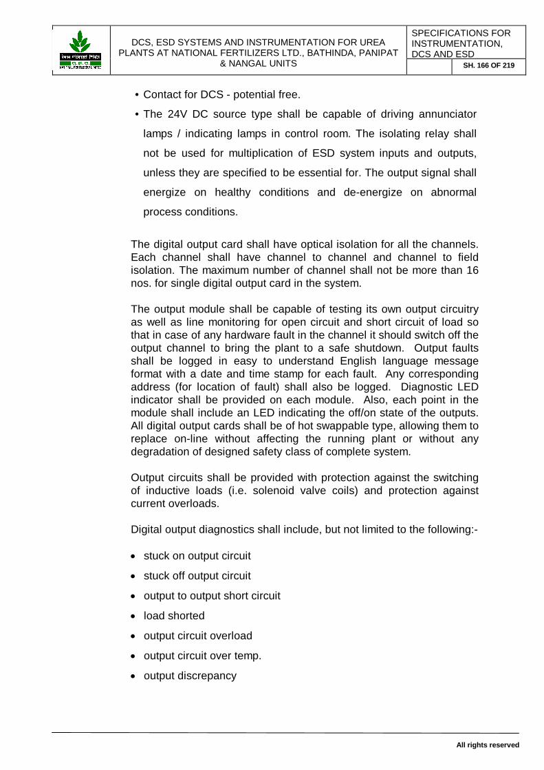
DCS, ESD SYSTEMS AND INSTRUMENTATION FOR UREA
PLANTS AT NATIONAL FERTILIZERS LTD., BATHINDA, PANIPAT & NANGAL UNITS
SPECIFICATIONS FOR INSTRUMENTATION, DCS AND ESD
SH. 166 OF 219
All rights reserved
• Contact for DCS - potential free.
• The 24V DC source type shall be capable of driving annunciator
lamps / indicating lamps in control room. The isolating relay shall
not be used for multiplication of ESD system inputs and outputs,
unless they are specified to be essential for. The output signal shall
energize on healthy conditions and de-energize on abnormal
process conditions.
The digital output card shall have optical isolation for all the channels. Each channel shall have channel to channel and channel to field isolation. The maximum number of channel shall not be more than 16 nos. for single digital output card in the system. The output module shall be capable of testing its own output circuitry as well as line monitoring for open circuit and short circuit of load so that in case of any hardware fault in the channel it should switch off the output channel to bring the plant to a safe shutdown. Output faults shall be logged in easy to understand English language message format with a date and time stamp for each fault. Any corresponding address (for location of fault) shall also be logged. Diagnostic LED indicator shall be provided on each module. Also, each point in the module shall include an LED indicating the off/on state of the outputs. All digital output cards shall be of hot swappable type, allowing them to replace on-line without affecting the running plant or without any degradation of designed safety class of complete system.
Output circuits shall be provided with protection against the switching of inductive loads (i.e. solenoid valve coils) and protection against current overloads. Digital output diagnostics shall include, but not limited to the following:-
stuck on output circuit
stuck off output circuit
output to output short circuit
load shorted
output circuit overload
output circuit over temp.
output discrepancy

DCS, ESD SYSTEMS AND INSTRUMENTATION FOR UREA
PLANTS AT NATIONAL FERTILIZERS LTD., BATHINDA, PANIPAT & NANGAL UNITS
SPECIFICATIONS FOR INSTRUMENTATION, DCS AND ESD
SH. 167 OF 219
All rights reserved
Module failure
3.2.4 Communications Interface
The ESD system shall function as nodes on safety system LAN to provide integrated safety system architecture. The system shall support standard ports for communicating with external devices such as DCS, local area network, etc. All communications ports shall permit connection and disconnection without interrupting system operation. Communication ports shall be configured to operate redundant, including all communication cable links. BIDDER to consider the length supported for diff. communication of ESD system parts to other devices, based on the distance between central cabinet room and engineering room/control room, for Engineering PC, SOE PC communication and DCS communication. External communication shall be provided by means of electrically isolated communication interfaces with redundant communication ports and paths. Said interfaces shall be powered by the system itself and shall use standard industrial communication protocols.
3.2.4.1 DCS – ESD COMMUNICATION INTERFACE
The ESD shall support the industry standard “MODBUS” RTU protocol over a two wire RS485 serial link, as a minimum. In the offer BIDDER should clearly highlight the make and model no. of DCS With whom the communication has been already established
through MODBUS serial communication.
With whom it can be part of the DCS network (as a node).
3.2.5 Operator Interfaces in CCR
DCS operator stations shall receive all ESD data and information through the redundant communication bus. (All process tags + ESD diagnostic messages). The status of all ESD input/output parameters including all internal memory variables, timers, counters, etc. shall be communicated to DCS. In DCS these shall be transferred as DCS

DCS, ESD SYSTEMS AND INSTRUMENTATION FOR UREA
PLANTS AT NATIONAL FERTILIZERS LTD., BATHINDA, PANIPAT & NANGAL UNITS
SPECIFICATIONS FOR INSTRUMENTATION, DCS AND ESD
SH. 168 OF 219
All rights reserved
tags. These shall be displayed on DCS graphic at Operator station. Hence no separate MMI software for ESD system is required. BIDDER to ensure that ESD system allows the transfer of all the ESD systems’ hardwired input/output and software parameters to be transferred to DCS without any limitation on number of tags/words/bytes and the communication/data update time at DCS shall be less than 1 second for complete PLC/ESD parameters. If with one set of gateways/communication paths, it is not possible to achieve the required band width, BIDDER shall provide additional gateways on ESD side to fulfil the above requirement.
In addition to this one ESD operator HMI PC station is envisaged for providing soft override switches POS/MOS (position override and operation/maintenance override).
4.0 Operations and functions 4.1 Overview The control room shall be made fully aware of the plant conditions on DCS console. In addition, alarms & status of ESD system shall be available for the following conditions or their equivalents:
Forced Any I/O which is forced on or off Communications active / fault Communications status Processor run / fault Fault conditions with CPU
Remote I/O active / fault Status of remote I/O
Battery Status of battery backing up static Fan failure Status of cooling fan Trip bypass Status of bypass switches I/O interface or address faults & I/O module faults .
4.2 System Status (CPU, I/O cards, etc.)
System diagnostics shall be presented on the Engg. Workstation and DCS with flashing points in alarm condition, turning to steady state upon alarm acknowledgement.

DCS, ESD SYSTEMS AND INSTRUMENTATION FOR UREA
PLANTS AT NATIONAL FERTILIZERS LTD., BATHINDA, PANIPAT & NANGAL UNITS
SPECIFICATIONS FOR INSTRUMENTATION, DCS AND ESD
SH. 169 OF 219
All rights reserved
4.3 Auxiliary Hardwired console
Auxiliary consoles shall be provided for high priority discrete hardwired safety functions, which shall be manually operated. The console shall be installed adjacent the operator station console, near 21” square model or 24” wide screen TFT /LCD type colour monitor in the central control room. The console shall be equipped with: Push button, Selector switches for emergency shut-down action only
Selector/Key switches for Over riding any trip parameters ( individual
switch for required override points in the interlocks)
Clustered LED type lamps, indicating override switch position,
RESET / READY to START condition of logic/interlocks, etc.
Lamp test
These consoles are in the DCS BIDDER‘s scope. However hooking up of required cables, wiring of individual lamps/switches between Consoles and ESD marshalling panel and relevant DI/DO cards shall be in the scope of ESD vendors. These shall be hardwired to ESD directly.
4.4 Transit Fault Alarm
Upon given shutdown order, transit fault alarm shall be given if, after a predefined time, a non-correct status shall be received from the field equipment. The transit fault time shall be defined for each output.
4.5 Manual Reset:
In addition to the individual reset facilities from operator stations, the system shall be provided with individual reset button for individual piece of interlock/logic, which shall light up when the reset is possible, i.e. the cause of the shut-down is cleared. When the pushbutton is pressed, the light in the button shall turn off and the related outputs could then be turned to normal status.
4.6 Sequence of Event Recording:
No separate Sequence of Events Recorder is envisaged. However, it is a must that the sequence of event recording function with 1 milli-second time resolution in a chronological order, shall be integral part of the ESD system. The PC running this software shall be equipped with 21” square model or 24” wide screen TFT /LCD type colour monitor and it shall be located in the central control room, along with other DCS operator stations. BIDDER to ensure the necessary hardware and software required shall be capable of recording the alarms and events with the resolution/time stamp of 1 milli second.

DCS, ESD SYSTEMS AND INSTRUMENTATION FOR UREA
PLANTS AT NATIONAL FERTILIZERS LTD., BATHINDA, PANIPAT & NANGAL UNITS
SPECIFICATIONS FOR INSTRUMENTATION, DCS AND ESD
SH. 170 OF 219
All rights reserved
The total no of points will be to the full capacity of the system, which shall include all input/output and intermediate memory variable of ESD. It shall be possible for the user to create a database of digital and analogue variables to observe and specify the parameter for collecting the data. The system should start automatically for collecting data on trip (initiator) without human intervention and stoppage of SOE program should be programmable in case of plant shutdown/maintenance, to avoid collection of unwanted alarms. The software shall record in chronological order on the hard disk of the dedicated PC. The software shall store the data in the list for user specified time before and after trip. The software shall allow the user to create display and print out to help to evaluate the system behavior. The software should be able to give the reports in the below listed formats as minimum: 1. Bar-chart
2. Trend line
3. Table
4. Static position and profile
5. Exporting events/alarms in Microsoft Excel Format, CSV file,
Text File or DBF/MDB file for database.
5.0 ESD System Software
5.1 Security
Different levels of password shall prevent memory programs modification from any external source. Hardware protection key shall also be provided.
5.2 Programming
Programming shall be kept simple through the use of common function blocks. Programming and downloading to running ESD system shall be possible both on-line and off-line.
5.2.1 PC based Programming Support
One engineering/programming workstation shall be provided to develop the control program, to diagnose system status, and, if necessary, to force points for loop check or maintenance of field sensors as per TŰV

DCS, ESD SYSTEMS AND INSTRUMENTATION FOR UREA
PLANTS AT NATIONAL FERTILIZERS LTD., BATHINDA, PANIPAT & NANGAL UNITS
SPECIFICATIONS FOR INSTRUMENTATION, DCS AND ESD
SH. 171 OF 219
All rights reserved
guidelines. Multiple application programming language capabilities shall be available as per IEC 1131 –3. BIDDER shall provide the details of the same. Methods for off-line debugging and program simulation in the development station shall be possible. The programming environment of ESD shall be Object Oriented; Microsoft Windows based, with all GUI features. Native DOS, NTVDM application built for DOS environment and ported to Windows NT/XP platforms are not acceptable. The application must be built from scratch for the proposed platform. Programming software, methodology and language supported shall conform to IEC1131 and shall be approved by TUV for designed safety class. As a minimum it should support Function Block Diagram method, structured text method and ladder logic method. Programming environment should support generic program and running of multiple instances of the same program with diff. set of input/outputs parameters. This engineering station shall be accommodated in the central engineering room, located in the close vicinity of Cabinet room. The interface between ESD main processor and programming station PC shall be via Ethernet with min. 10 MBPS speed. ESD system application software shall allow incremental download to carry out online modifications, without affecting the running plant. There shall be facilities to monitor the running logic in FBD format in real time mode from engineering station. Also the engineering station of ESD shall allow forcing of any of the hardware input/output or intermediate local variables in complete system by software method.
5.3 Software Utilities
The following software utilities/tools or equivalent functions shall be provided by BIDDER as a minimum: Industry standard relay ladder logic,
Boolean operators with timing and voting functions,
High-level language like C, C++, VB, etc.
System diagnostic,
On-line data changes.
Cause-effect table
Print utility
Emulation Software, which can emulate complete ESD application
without needing I/O cards and without affecting I/O Cards
status/running application.

DCS, ESD SYSTEMS AND INSTRUMENTATION FOR UREA
PLANTS AT NATIONAL FERTILIZERS LTD., BATHINDA, PANIPAT & NANGAL UNITS
SPECIFICATIONS FOR INSTRUMENTATION, DCS AND ESD
SH. 172 OF 219
All rights reserved
Simulation test software and methods
Fault injection and diagnostic / clearance method
Offline engineers and database building package tools.
System software shall also include the software to configure the
communication link between DCS and ESD based on MODBUS
or any other standard protocol.
Significant feature and characteristics of the interface shall include
a. Availability of data in the interconnected ESD which will allow the
DCS to integrate in display Data from ESD and to centralise
monitoring of ESD operating status in DCS, including all ESD I/O,
intermediate memory variable status, timers, counters, ESD health
status flags, in real time environment.
5.4 Configuration
BIDDER shall be required to develop application programs which perform the logic sequence and functionality as indicated on logic diagrams or cause and effect charts supplied by Owner. The application program shall be structured to keep similar programming features grouped together.ESD shall have facilities to communicate with proposed DCS and preferably it should sit on DCS network as one of the DCS node, so that seamless integration of DCS / ESD-ESD could be achieved. MMI software for ESD/ESD is not envisaged / required, as all ESD events shall be monitored on DCS in graphical environment via this software communication link over MODBUS or better solution as prescribed above. These include the entire Digital input/output channel’s real time status, intermediate local/global ESD variables, timers, counters, all the analog input channels real time values in floats, etc. There shall not be any tag/parameter limits on DCS/ESD gateway communication and the update time of complete ESD parameter sets on DCS shall not take more than 1 second. The following sequence of grouping is suggested:
Common internal logics : if grouping of the same input contact
status are used repeatedly throughout the program, combine them

DCS, ESD SYSTEMS AND INSTRUMENTATION FOR UREA
PLANTS AT NATIONAL FERTILIZERS LTD., BATHINDA, PANIPAT & NANGAL UNITS
SPECIFICATIONS FOR INSTRUMENTATION, DCS AND ESD
SH. 173 OF 219
All rights reserved
into common internal logics for easy programming and memory
savings.
Data which are interfaced to external systems should be grouped
together to facilitate block transfer of data. Sufficient comments and
descriptions shall be included throughout all ladder logic networks
to help operators and maintenance personnel.
5.5 Diagnostics
Each CPU shall incorporate self-diagnostic routines, I/O status checks ,loop back verification, STUCK ON/STUCK OFF status checks, memory bit pattern checks, CRC checks, watchdog timer to determine the health of each module within the ESD system. Diagnostic routines shall run without interfering with application program scan or execution time within the process safety time. On-line diagnostics shall include but not be limited to the following; memory testing, data and address line testing , processor testing , Interrupt testing , timer testing, memory battery testing, firmware CRC testing , Application program testing , data fault , I/O interface testing , Input discrepancy check ( digital & analog) & output discrepancy check .
The programmes should preferably be in firmware and the use of application software based test programmes should be avoided. The BIDDER shall detail the basis of the design including a statement on how test software will be generated to match revised application logic. BIDDER shall state the optimum frequency for the automatic self-test routine necessary to maintain the requirements of system availability, reliability and safety.
The result (healthy/fault) of the self-test shall be reported on the DCS at the CCR through Communication bus and also on the engineering workstation (PLC ) . Should a fault be detected, and where there is redundancy of design, the system shall automatically adapt to maintain its ability to meet a demand. The BIDDER shall identify in his bid all possible types of faults in his system and for each type and describe the method of

DCS, ESD SYSTEMS AND INSTRUMENTATION FOR UREA
PLANTS AT NATIONAL FERTILIZERS LTD., BATHINDA, PANIPAT & NANGAL UNITS
SPECIFICATIONS FOR INSTRUMENTATION, DCS AND ESD
SH. 174 OF 219
All rights reserved
detection, the resulting system performance degradation, system status after the fault and the time required for detection of fault. This fault analysis has to be implemented by way of failure mode and effect analysis and severity of fault level must be reported in the diagnostic report to take corrective action immediately. The BIDDER shall explicitly detail in his bid all types of faults which may not be detected by the proposed / implemented diagnostics and self tests and propose measures / procedures to overcome this problem and precaution to be taken to achieve class 6 protection as per TŰV.
6.0 CABINETS / PANELS
The complete system shall be supplied with either 1200 mm (W) x 800 mm (D) x 2100 mm (H) or 800 mm (W) x 800 mm (D) x 2100 mm (H) standard RITTAL make panels with RAL7032 colour shade. These shall be self standing type with front and rear doors. All cabinets, wherever applicable, shall have 4 cooling fans at the top, protected by canopies. High quality & washable type filters shall be provided at the bottom of front & rear doors. Cabinets shall be provided with an internal ventilation system, in order to extract the heat produced by electronic circuits assuring that all devices properly work in the specified temperature range. Each cabinet shall be provided with 4 ventilation louvers ( one on each door, two on front side, two on back side at bottom) of 5-micron size with wire mesh to prevent dust & rodent at bottom only. A temperature measuring system shall also be provided to generate a potential free digital alarm signal in case the temperature exceeds the set value for each panel. Fans shall be suitable for continuous operation and mounted on self-lubricated bearings. All the fans shall run on 115 V AC power supply.
6.1 Marshalling /AUX Cabinets 6.1.1 All the trip/interlocks related field signals (analog inputs, digital inputs,
digital outputs) shall be individually wired from isolator panles to central cabinet. At central cabinet room these shall be terminated at desired destination marshalling cabinet of ESD. These marshalling cabinets shall be used to terminate all field cables as well as for grouping of various signals from the field devices, properly tagged ferruled tested and terminated. This will be applicable for all and any type of terminations. There shall be diff. panels for diff. types of signals. Mainly, there shall be separate panels for analog inputs, digital inputs and digital outputs/relays.

DCS, ESD SYSTEMS AND INSTRUMENTATION FOR UREA
PLANTS AT NATIONAL FERTILIZERS LTD., BATHINDA, PANIPAT & NANGAL UNITS
SPECIFICATIONS FOR INSTRUMENTATION, DCS AND ESD
SH. 175 OF 219
All rights reserved
BIDDER shall provide sufficient terminals for all field cables including spare cores terminated and 20% spare terminals surplus with equal distributions. In the system and marshalling cabinets, the cabinets shall have facilities for supporting all cables throughout the length of their run within the cabinet. Cable clamping arrangement shall be provided to secure all cables where they leave the cabinet. Cable tray / trunking shall be sized to have 30% spare capacity after all cabling and wiring has been installed. Internal wiring shall be done inside all closed PVC troughs with proper cross ferruling. The detail specifications of internal panel wiring/colour codes and ferruling are specified in further sections are to be followed.
6.1.2 These shall also be used to mount other hardware like signal
conditioning cards, safety barriers, R/I, mV/I converters, relays as well as any free issue material supplied by OWNER. Details of such items are as per Part-II of the specification.
6.1.3 Marshalling racks shall be self standing type with front & rear doors.
Each cabinet will have its cabinet identification attached to the cabinet front door with SS screws. Each rack & component shall have its own identification label corresponding to BIDDER documentation.
6.1.4 Dimensions & colour of all marshalling cabinets shall be identical from
point of view of good aesthetics. For all type panel/cabinets, the panel size shall be either 1200mm (W) x 800mm (D) x 2100mm (H) or 800mm (W) x 800mm (D) x 2100mm (H), RITTAL make only with RAL7032 colour shed. No other type of panel/cabinets shall be acceptable. Generally marshalling panels shall be with 1200mm width and system hardware panels shall be based on system architecture ( either 600 mm wide or 1200 mm wide).
6.1.5 All the cabinets shall be provided with door locks and it should be
possible to open all of them with a single key. Door handles shall be flush type.
6.1.6 Painting shall be powder coating, with matt finish and RAL7032 colour
shed. 6.1.7 100-mm channel base (Black colour, powder coated) shall be
provided at the bottom for mounting. 6.1.8 Removable gland plates for all cables shall be provided at the bottom.

DCS, ESD SYSTEMS AND INSTRUMENTATION FOR UREA
PLANTS AT NATIONAL FERTILIZERS LTD., BATHINDA, PANIPAT & NANGAL UNITS
SPECIFICATIONS FOR INSTRUMENTATION, DCS AND ESD
SH. 176 OF 219
All rights reserved
6.1.9 For prefabricated system cables between marshalling racks and system hardware cabinets a separate gland plate with split holes & rubber grommets shall be provided. Bunching of cables and routing them through a single big cutout is not permitted.
6.1.10 The design of marshalling panels shall be such that whenever a
group of panels is bolted together it shall be easily possible to do inter wiring within the panels. Clubbing of same type of max. 2 panels of 1200 mm width is permissible. Use of external cabling to do interconnection between panels shall be restricted only to those cases where panel/group of panels are geographically separate from one another.
6.1.11 Internal layout of marshalling racks shall ensure that there is no
overcrowding of components and maintenance accesses are properly obtained. Terminal strips shall be easily accessible and ferrules readable. All components shall be mounted on front and rear surfaces of the mounting plate. No component shall be mounted on the sides/doors/gland plates or in the bolting space provided between two adjacent cabinets.
6.1.12 Detailed specification of different types of marshalling rack is
as per Part-II of this specification. 6.1.13 Marshalling / system hardware cabinets lay-out in central cabinet
room shall be designed in such a way that there shall be min. 1000 mm distance in front and back side of each panel is available for maintenance and human movement, safely.
6.1.14 These shall be provided with a separate system earth bus bar
insulated from ground and a separate safety earth busbar connected with panel body. There shall be min. two nos. of bus bar ( 1 of each type) on both side of panels.
6.1.15 The qty. of marshalling panels shall be based on total I/O counts,
20% spare loading space for future margin, proper type of I/O segregation and as per OWNER’s requirement, as specified in above section.
6.2 System Hardware Cabinets 6.2.1 These shall be used to mount the system hardware. 6.2.2 All the specifications shall be strictly same as those of marshalling
cabinets. However there are two options available in dimensions, viz.

DCS, ESD SYSTEMS AND INSTRUMENTATION FOR UREA
PLANTS AT NATIONAL FERTILIZERS LTD., BATHINDA, PANIPAT & NANGAL UNITS
SPECIFICATIONS FOR INSTRUMENTATION, DCS AND ESD
SH. 177 OF 219
All rights reserved
1200mm(W) x 800mm(D) x 2100mm(H) or 800mm(W) x 800mm(D) x 2100mm(H), based on system architecture. However, BIDDER to ensure that all other specifications shall remain same as specified above in marshalling panel details.
6.2.3 These shall be provided with a separate system earth bus bar
insulated from ground and a separate safety earth busbar connected with panel body. There shall be min. two nos. of bus bar ( 1 of each type) on both side of panels.
6.2.4 The qty. of system panels shall be based on total I/O cards, system
hardware modules, 20% spare loading space for future margin on both side and with proper type of Common/Central System hardware as well diff. type of I/O cards segregation and as per OWNER’s requirement, as specified in above section. In main system hardware panel, which will accommodate central ESD parts, will not accommodate any other type of I/O cards/ marshalling inputs/outputs. Also, there shall be diff. / separate cabinet for diff. type of input/output cards.
6.3 Power Distribution Cabinets 6.3.1 These shall be used to mount the hardware required to distribute
power at various voltage levels and types to the system. The total number of HRC fuses required shall accommodate extra 50 points on each side ( Total 100 points). The distribution shall be on front and back side. No components/fuses/feeders shall be installed / terminated on both sides of adjacent panels.
6.3.2 These shall be exactly same in all specifications as mentioned in
marshalling and system hardware panels, except the dimensions. For all type of PDB, the panel size shall will be 1200mm(W) x 800mm (D) x 2100mm(H). These shall be self-standing type with front and rear doors.
6.3.3 Other specifications remain identical to those of marshalling cabinets. 6.3.4 Vendor shall provide required no. of 115 V AC , 50 Hz main supply
feeders up to PDB main isolation switches. PDB shall be equipped with double pole, rotary isolation switches with mains HRC fuses with suitable terminators. OWNER shall provide power at incomers of rotary switch only. Further wiring/distribution, sub-distribution shall be carried out by BIDDER. MCB shall not be used at any location. Main feeder and sub feeders shall be provided with HRC fuses/sockets for individual load.
6.3.5 BIDDER to provide fuse co-ordination details, calculations for internal
distribution for above all PDB.

DCS, ESD SYSTEMS AND INSTRUMENTATION FOR UREA
PLANTS AT NATIONAL FERTILIZERS LTD., BATHINDA, PANIPAT & NANGAL UNITS
SPECIFICATIONS FOR INSTRUMENTATION, DCS AND ESD
SH. 178 OF 219
All rights reserved
6.3.6 If system requires a separate 24 V DC power supply, BIDDER shall
provide 100% redundant 24 V DC bulk power supply in these PDB panels with all mounting hardware, diode paralleling unit and other accessories. The individual 24 V DC bulk power supply unit in a pair or redundant units shall be designed with 130% load carrying capacity. This is required to ensure the catering of complete from single bulk power supply from a redundant pair, in case of failure of any one of the power supply. The complete system shall be designed with 50% spare future margin.
6.3.7 The qty. of PDB panels shall be based on total sub feeder
requirement, diff. type of voltage levels, 20% spare loading space for future margin on 110 V AC side and 50% spare future margin on 24 V DC bulk power supply side as per OWNER’s requirement.
6.3.8 All the PDB shall have min. 3 receptacles for 230 V AC/5 Amp
distribution inside panel. 6.4 Interconnection Cables 6.4.1 All cables inside the cabinet ( e.g. power supply , internal bus etc
) as well as any cable from cabinet to cabinet , shall be labeled properly with the cable number on both ends . The labeling shall include also the destination of each cable end. For details refer to Part-II of the specification. Different cables running between various panels inside the cabinet room , below the false floor shall armoured type. These shall be laid in perforated aluminium cable trays below the false flooring, in different trays, with proper segregation like 110 V AC power supply, 24 V DC power supply, signal cables, communication cables, etc. All communication cables shall run thru’ Flexible PVC conduits only, within the panel and between the panels.
6.5 Ventilation
Cabinets shall be provided with an internal ventilation system, in order to extract the heat produced by electronic circuits assuring that all devices properly work in the specified temperature range. Each cabinet shall be provided with 4 ventilation louvers ( one on each door, two on front side, two on back side at bottom) of 5-micron size with wire mesh to prevent dust & rodent at bottom only. A temperature measuring system shall also be provided to generate a potential free digital alarm signal in case the temperature exceeds the set value for each panel.

DCS, ESD SYSTEMS AND INSTRUMENTATION FOR UREA
PLANTS AT NATIONAL FERTILIZERS LTD., BATHINDA, PANIPAT & NANGAL UNITS
SPECIFICATIONS FOR INSTRUMENTATION, DCS AND ESD
SH. 179 OF 219
All rights reserved
Fans shall be suitable for continuous operation and mounted on self-lubricated bearings. All the fans shall run on 115 V AC UPS power supply.
6.6 Wire Termination
All the terminals for connecting field cables shall be WAGO make, screw less, side-side entry type suitable for 0.5 sqmm to 4 sqmm cables. No looping of common terminals shall be done on the terminals. All outputs for solenoid valves shall be provided with WAGO make, screw less, side-side entry type, fused terminals with LED indication. Wiring shall be PVC insulated 600-volt grade with copper conductor. Power cable shall be 600 / 1100 volt grade. Conductor shall be multi strand type and size shall be as mentioned below. For analog inputs :- 2.5 sq mm, multi strand 12 pair or single pair individual/overall shielded with white (+) / Black (-) colour codes. For Digital Inputs :- 2.5 sq mm, multi strand, flexible, 12 pair or single pair individual/overall shielded with Grey (+) / Grey(-) colour For Digital Outputs:- 2.5 sq mm multi strand, flexible, 12 pair or single pair individual/overall shielded with Red (+)/Blue (-) colour For 110 V AC power cable:- 3 Core, multi strand, flexible, RED(P) / BLACK (N) /GREEN (E), Sizing shall be based on load, however min. size shall be 2.5 sq.mm. For 24 V DC power cable :- 2 core, multi strand, flexible, RED (+)/ Blue (-), sizing shall be based on load, however min. size shall be 2.5 sq.mm. Adequate segregation of terminals and accordingly marshalling panels and wiring shall be maintained to allow quick identification of wires. The broad segregation is provided below:
Discrete inputs
Discrete outputs thru Relays for Solenoid valves
Discrete outputs thru Relays for Solenoid valves
Analog inputs
Output to Annunciator / Lamp
Output to MCC

DCS, ESD SYSTEMS AND INSTRUMENTATION FOR UREA
PLANTS AT NATIONAL FERTILIZERS LTD., BATHINDA, PANIPAT & NANGAL UNITS
SPECIFICATIONS FOR INSTRUMENTATION, DCS AND ESD
SH. 180 OF 219
All rights reserved
Output to DCS
Power supply
The system cables used between the marshalling cabinets and the system cabinets shall be supplied by the BIDDER in a prefabricated form and pre-connected at the ESD BIDDER factory to the respective cabinets. Termination boards shall be provided with suitable input/output connectors for quick interconnection. It shall be BIDDER’s responsibility to select proper type of terminal assly. For each cards of system.
No more than two wires shall be connected to a single terminal block connection. The second wire, if necessary, shall be a jumper wire to an other terminal. Spare terminal shall be provided for the future use as per PART –II.
6.7 Internal Wiring
I/O and interconnecting wiring shall be tagged at each end with the identification tags. Ferruling shall be double cross ferruling with continuous sleeve. No discrete ferrules shall be accepted. There shall be uniform colour codes for ferrule sleeves various type of signals. All system cable/wire ferrules shall be of white colour with black fonts, whereas all other ferrule sleeve colour shall be yellow with black fonts.
6.8 Power Supply
- Voltage: 115 VAC + 10 % - Frequency: 50 HZ +3 % & -6% Vendor shall provide required number of main feeders with above UPS grade power supply at incomers of PDB rotary switches. Further conversion to diff. levels, sub-distribution, etc. shall be in the scope of BIDDER Each load shall be capable of accepting 110 V AC from two diff. source. Also all devices running on 24 V DC shall also be capable of accepting redundant Electrical power supply from 24 V DC bulk power supply system designed and supplied by BIDDER inside PDB. System shall withstand transient voltage spikes of 140% for a period of 10 ms . System shall withstand momentary loss of complete power for 40 milli seconds.

DCS, ESD SYSTEMS AND INSTRUMENTATION FOR UREA
PLANTS AT NATIONAL FERTILIZERS LTD., BATHINDA, PANIPAT & NANGAL UNITS
SPECIFICATIONS FOR INSTRUMENTATION, DCS AND ESD
SH. 181 OF 219
All rights reserved
6.8.1 Internal DC Power Supplies
A dedicated redundant power supply unit, included in the scope of supply, shall be used to feed power to racks of the system. Each power supply unit shall be sized to provide 130 % of required capacity for the specified configuration of I/O cards, CPUs, including installed spare modules. Each power supply unit shall have built in diagnostic, circuitry to monitor out of range voltages and over temperature conditions and diode ORing circuits. Each power supply unit shall have its own internal fuse/circuit breaker protection on the incoming line side.
BIDDER shall carry out a fuse co-ordination study to ensure that in case of a short circuit only the directly protecting fuse or circuit breaker interrupts the circuit and no higher level fuse melts or circuit breaker opens.
Any external power supply such as to drive 24V DC interposing relay , transmitters, and interrogation voltage shall be TUV approved, fully redundant, modular with voltage, current indication and adjustable with cooling fans and potential free contacts for alarm. If the BIDDER’s requirement require dedicated grounds the proposal shall include sufficient information to determine how these grounds are to be arranged. The BIDDER shall include heat dissipation requirement in his proposal so that air conditioning system can be sized. The BIDDER is to include the power load requirements in the proposal that the battery system can be sized. BIDDER shall provide complete Single Line Diagram of complete PDB systems including 110 V AC and 24 V DC power supply distribution with proper fuse co-ordination calculation, heat dissipation data, etc.
6.8.2 Power system Indicators
Power supply unit status shall be indicated on the faceplate of PDB panel doors from outside with the help of Digital Voltmeters and shall be remotely communicated via alarm contacts and software. Which will be wired to DCS and annunciated in DCS operating station.

DCS, ESD SYSTEMS AND INSTRUMENTATION FOR UREA
PLANTS AT NATIONAL FERTILIZERS LTD., BATHINDA, PANIPAT & NANGAL UNITS
SPECIFICATIONS FOR INSTRUMENTATION, DCS AND ESD
SH. 182 OF 219
All rights reserved
6.9 Grounding / Earthing
There shall be 2 type Earthing points, one shall be insulated system earth bus bar and the other shall be safety earth bus bar. There shall be total 4 nos. of such Earth bus bar provided in the each cabinet ( two on either side). The looping of the Earthing points should be in such a way that a break in one circuit will not affect complete earthing . Both the earthing points will be provided at a single point . Inside the cabinet this shall be done by the BIDDER. A ground fault detection circuitry shall monitor floating electrical circuits in field wiring via an alarm indicator, when resistance to earth fails for all types of I/O. BIDDER to specify total numbers of earthpits. All inter panel and system component grounding/earthing shall be carried out by BIDDER inside cabinet room, with 100% redundant looping. OWNER shall provide two separate earth bus bar in cabinet room at one location. BIDDER to lay all earthing/grounding cable up to this point.
7.0 Name and Tag Plates
Each instrument, equipment, cabinet, panel included in BIDDER’s scope of supply shall have its individual name and tag plate which matches with the documents submitted . All name and tag plates, or plates for brevity, shall be designed and supplied by the BIDDER which will be made of black Acrylic sheet and screwed with SS screw to the panel. Tag numbers shall be engraved or embossed in white colour only. The naming philosophy shall be as per OWNER requirement.
8.0 System Availability The ESD system (Emergency Shutdown system) availability shall be in the excess of 99.99% and the mean time between failure for all components in the ESD system should be not less than 12 hours. The BIDDER should quote spares for the system so that the mean time to repair the system should be below 12 hours.
9.0 TRAINING BIDDER shall train OWNERs’ maintenance engineers as well as operations staff in his works. The training imparted shall be by qualified and experienced staff available. It shall be exhaustive and aimed at making OWNERs’ maintenance & operations staff self reliant for most of the day to day applications. For training, supplier shall make available as close a model of the system with all the representative nodes, as the actual system to be installed. The BIDDER shall prepare the teaching material and shall

DCS, ESD SYSTEMS AND INSTRUMENTATION FOR UREA
PLANTS AT NATIONAL FERTILIZERS LTD., BATHINDA, PANIPAT & NANGAL UNITS
SPECIFICATIONS FOR INSTRUMENTATION, DCS AND ESD
SH. 183 OF 219
All rights reserved
provide all equipment and tools necessary including copies of course material It is envisaged that following be covered in the training: 9.1 Maintenance Staff Training a. System architecture.
b. Functions of each node.
c. Hardware in each node.
d. Complete application software.
This shall cover everything from basics like generation of various system nodes to advance language programming, configuration and debugging etc.
e. Commonly occurring hardware problems and the maintenance procedures to be followed.
f. Various diagnostic programmes available and their use and interpretation.
g. Routine preventive maintenance procedures and Maintenance of various peripheral devices like printers, copiers etc.
h. Maintenance procedure to be followed as per TUV guidelines.
DCS, ESD SYSTEMS AND INSTRUMENTATION FOR UREA
PLANTS AT NATIONAL FERTILIZERS LTD., BATHINDA, PANIPAT & NANGAL UNITS
SPECIFICATIONS FOR INSTRUMENTATION, DCS AND ESD
SH. 184 OF 219
All rights reserved
9.2 Operations Staff Training
This shall be restricted to the operation of the system. This shall broadly cover the following: a. System architecture.
b. Functions of each node.
c. Functions of various keys in the keyboard.
d. Generation of displays like graphics, group, trend groups, etc.
e. Display hierarchy, access methods for various displays, switching
between different types of displays etc.
f. Control of plant from various displays.
g. Alarm handling.
h. Developing special programmes for plant control and their
debugging (Restricted to supervisory staff only).
i. Logging software.
9.3 The requirement of operational/ maintenance training
shall be as under:
6 Instrument engineers x one week each at vendor’s works.
6 Process engineers x one week each at vendor’s works.
Two Weeks training for Two Instrument engineers from each unit for ESD, at vendor’s centre of excellence.
10.0 INSPECTION
10.1 The system and all its 100 % associated components shall be
inspected and tested at the BIDDER’s works by OWNER & third party (if required).
10.2 OWNERs reserve the right to inspect any bought out items by the
BIDDER at the sub- BIDDER’s works. 10.3 Cost of inspecting/testing shall be borne by the BIDDER. FAT/SAT
procedures to be submitted with offer.

DCS, ESD SYSTEMS AND INSTRUMENTATION FOR UREA
PLANTS AT NATIONAL FERTILIZERS LTD., BATHINDA, PANIPAT & NANGAL UNITS
SPECIFICATIONS FOR INSTRUMENTATION, DCS AND ESD
SH. 185 OF 219
All rights reserved
10.4 For final integrated inspection of the system, the BIDDER shall give a minimum notice of 3 weeks to OWNER. Through out the Factory acceptance test, BIDDER shall provide all necessary test equipments and consumables and shall make all necessary connection as many times required. OWNER shall carry out 100% functional checking of all hardware and software modules.
10.4.1 Acceptance testing BIDDER shall prepare test procedures for
Owner’s approval. Level of testing:
Beyond the mandatory test and inspections according to BIDDER's quality assurance program during fabrication there shall be two testing described as follows:
1. Factory acceptance test (FAT) to be performed at the BIDDER's factory. 2. Site acceptance test to be performed on plant site.
10.4.2 Factory acceptance test (FAT)
The FAT shall be performed when the complete system, including all hardware and software components, to be supplied by the BIDDER, has been assembled and prepared for operation in the factory. The testing procedures shall be performed with the aid of adequate simulation hardware, software And / or test programs. The objective of the testing procedures is to ensure that all hardware components and the related software modules (standard function blocks) are free from errors/defects when being tested individually and in the system configuration. The tests shall be performed with the aid of test programs permitting easy location of defective components and/or software modules.
During the factory acceptance test, the complete system must remain 100 % operational for at least 100 consecutive hours with no hardware and/or software failures. The BIDDER shall provide test and simulation equipment, appropriate testing staff and any service utilities to perform the test in an efficient and timely acceptable manner. The course and duration of the test procedure shall be specified by the BIDDER. Simulation equipment for simultaneous testing of 100 % of I/O-signals shall be kept available by the BIDDER/manufacturer (with multiple plug-in connectors).

DCS, ESD SYSTEMS AND INSTRUMENTATION FOR UREA
PLANTS AT NATIONAL FERTILIZERS LTD., BATHINDA, PANIPAT & NANGAL UNITS
SPECIFICATIONS FOR INSTRUMENTATION, DCS AND ESD
SH. 186 OF 219
All rights reserved
The Owner and the BIDDER shall agree upon the start of the test. If any failures occur within said 100 hours the test shall be restarted when the failure has been corrected and the system shall be re-tested for another 100 consecutive hours. During FAT BIDDER shall prepare a report signed by the Owner and the BIDDER. After the factory acceptance test has been successfully completed the system shall be ready for transportation to plant site.
Additionally the communication between ESD–system and DCS shall also be tested. The procedure, e.g. simulation or test program has to be clarified between Owner and BIDDERS.
10.4.3 Site acceptance test (SAT)
After transportation to plant site the BIDDER has to investigate and prove all system components and devices against transportation and erection damages. This level of testing will take place on site after the system has been installed and certified as operational by the BIDDER. The BIDDER shall have the responsibility to ensure that the installed hardware including the software supplied is fully operational. The testing procedure shall include mechanical checks of the system including all system links connected according to the BIDDER's specification. After this the software will be loaded and self-test routines of the EDS-system shall ensure that all system components are in acceptable condition as well as the communication links are working properly. The application software will be loaded. If the system shows no deviation to the normal operation, the system will be ready for loop checks. When the system operates normally for continuously 30 days, after completion of the loop checks and all simulation test, the ESD-system shall be considered as accepted by the Owner.
All guarantee performance data which are specified (CPU spare capacity, spare capacity of hardware, scanning time of process variables etc.) will be proven by BIDDER.

DCS, ESD SYSTEMS AND INSTRUMENTATION FOR UREA
PLANTS AT NATIONAL FERTILIZERS LTD., BATHINDA, PANIPAT & NANGAL UNITS
SPECIFICATIONS FOR INSTRUMENTATION, DCS AND ESD
SH. 187 OF 219
All rights reserved
A certificate of acceptance shall be signed by the representatives of the Owner and BIDDER.
10.5 The inspection shall briefly envisage the following: 10.5.1 Hardware Inspection
a. Checks on general workmanship like fabrication quality, paint quality, whether paint shade identical to all cabinets etc.
b. Dimensional inspection for base frame, height, depth, gland plates etc.
c. Power supply, wiring checks for fans, tubelights etc.
d. Supply/signal wiring checks including colour code checking, checking of ferrules, correctness of wiring, size of wires, proper segregation of wires etc.
e. Provision of terminals of correct size and type.
f. Operations of various lamps, push buttons, MCBs, annunciators, relays, ammeters and other instruments mounted on the consoles or within the cabinets.
g. Megger test for power distribution cabinets.
h. Provision of earthing busbars for safety earth/intrinsic safety earth.
i. If a group of panels/consoles is to be mounted and bolted together in the final layout frozen the same shall be offered for inspection exactly in the same fashion to check inter panel wiring, mechanical alignment etc.All system modules shall be checked for their correct mountings in respective slots as per configuration frozen.
j. Redundancy and failsafe features wherever specified shall be checked for:
i. Power supply.
ii. I/O cards.
iii. CPU/CPUS.
iv. Communication (between nodes as well as within a node).
k. Scan times as specified shall be checked for all inputs/outputs, including installed spare I/Os in the system.
l. Individual modules wherever possible shall be checked for their performance with redundancy and fault tolerance checking.
m. All volatile memory shall be checked for battery backup by tripping power for the duration given in the BIDDER’s specifications.

DCS, ESD SYSTEMS AND INSTRUMENTATION FOR UREA
PLANTS AT NATIONAL FERTILIZERS LTD., BATHINDA, PANIPAT & NANGAL UNITS
SPECIFICATIONS FOR INSTRUMENTATION, DCS AND ESD
SH. 188 OF 219
All rights reserved
n. Generating the trip signals and checking the performance of SOE.
10.5.2 Software Checks These shall include, but not limited to, the following:
a. 100% check on the generated data base. This includes checks on:
i. Correctness of tag number and description. ii. Measuring range. iii. Input type, input conditioning. iv. Algorithms to be executed. v. Output type and conditioning if any. vi. Logic. vii. Other details if required.
b. Logging operation shall be checked in sequential Event
recorder c. Communication with external device to be checked including
DCS. d. S.O.E. history and interface software checks.
11.0 INSTALLATION, PRE-COMMISSIONING AND COMMISSIONING.
BIDDER shall depute a team of experienced engineers, technicians and other staff for the purpose of installation, pre-commissioning and commissioning of the system at site. Following activities are included in the BIDDER’s scope:
a. Receipt of system hardware and software at site store and transportation of system from site stores to cabinet room.
b. Unpacking the system and inspection of the same for any damages.
c. Erection of system in control room/cabinet room; including welding of channel supports in false floors.
d. Inter cabinet wiring/cabling for all signal, power supply and system cables.
e. System and Safety earthing of all panels from a busbar given at one point in console/cabinet room.
f. Intrinsic safe earthing of all panels from a separate busbar given at one point in console/cabinet room.

DCS, ESD SYSTEMS AND INSTRUMENTATION FOR UREA
PLANTS AT NATIONAL FERTILIZERS LTD., BATHINDA, PANIPAT & NANGAL UNITS
SPECIFICATIONS FOR INSTRUMENTATION, DCS AND ESD
SH. 189 OF 219
All rights reserved
g. Mounting of all hardwired instruments like signal distributors in various cabinets; calibration & programming of these instruments for ranges, set points etc.
h. Mounting, wiring and termination of all free issue instruments given by the OWNERs and listed in Part-II of project specification.
i. Powering up the system, loading the system configuration and carrying out internal loop checks for correctness of wiring is in BIDDER’s scope. This shall be carried out from marshalling cabinets upto system cabinets. It also includes checking of the software by hardware simulation. The completion of this activity marks the “mechanical completion” of the system and the protocol to this effect shall be jointly signed by the OWNERs/OWNER and the BIDDER.
j. Coordination with OWNERs/OWNER/site erection contractor during complete loop/interlock checking of the plant. This shall be done atleast at 4 points in instrument range and with printer online.
k. Consolidate all loop-checking reports with OWNERs/OWNER.
l. Correction of all drawings to make them “as built”.
m. Provide commissioning assistance to OWNERs/Licensor in the form of implementing configuration and interlock changes etc. required during commissioning of the plant.
n. BIDDER will arrange all necessary tools and equipment's like welding machine etc. for erection of system cabinets / consoles and cable laying, glanding and termination.
12.0 FINAL ACCEPTANCE & WARRANTY OWNER shall take over the system from BIDDER after site acceptance test. The integrated system shall run uninterruptedly for four weeks from date of commissioning of the whole plant. Any loss of time due to reasons like power failures, forced shutdowns etc. which are due to no fault of the BIDDER shall also be counted as run time. However, if any major software/hardware failure of the system occurs due to which the system or a part thereof has to be shutdown the test shall be conducted afresh on the whole system. The warranty period shall be 12 months from final site acceptance test of the system. During warranty period BIDDER shall make good all failed components of any part of the system and depute his service engineer to site if required free of cost.

DCS, ESD SYSTEMS AND INSTRUMENTATION FOR UREA
PLANTS AT NATIONAL FERTILIZERS LTD., BATHINDA, PANIPAT & NANGAL UNITS
SPECIFICATIONS FOR INSTRUMENTATION, DCS AND ESD
SH. 190 OF 219
All rights reserved
13.0 DOCUMENTATION / DRAWINGS Documents / drawings shall be supplied as per requirement given below:
SR.NO.
ITEM NO. OF COPIES
With quotation
For approval after P.O.
After approval for information
After Factory Acceptance test
Final / As-built
a. Architecture (one line diagram) of the quoted system.
2 for each site
2 for each site
2 for each site -
3 for each site
b. Detailed bill of material upto module level & including all bought out auxiliary items.
2 for each site
2 for each site
2 for each site -
3 for each site
c. Bill of material, make/model number, with catalogues for all bought out items.
2 for each site
2 for each site
2 for each site -
3 for each site
d. Proposed organisation chart for job execution. - 2 for
each site - - -
e. Detailed schedule of job execution. 2 for
each site 2 for each site
f. A copy of unfilled standard engineering formats which shall be filled in by OWNERs/OWNER during engineering.
2 for each site
2 for each site
g. Standard dimensional drawings for:
1. System cabinets/ marshalling cabinets/ power distribution cabinets with cabinet arrangement duty.
2 for each site
2 for each site
3 for each site
3 for each site
2. Peripherals like printers. 2 for
each site 2 for each site
3 for each site
3. Recommended spare parts list for 2 years operation after FAT.
2 for each site
2 for each site

DCS, ESD SYSTEMS AND INSTRUMENTATION FOR UREA
PLANTS AT NATIONAL FERTILIZERS LTD., BATHINDA, PANIPAT & NANGAL UNITS
SPECIFICATIONS FOR INSTRUMENTATION, DCS AND ESD
SH. 191 OF 219
All rights reserved
h. Final layout drawings including internal hardware mounting details. 2 for
each site 2 for each site
3 for each site
3 for each site
i. Calculation of total power requirement.
2 for each site
2 for each site 3 for
each site j. Expected heat
dissipation. 2 for each site
2 for each site 3 for
each site k. Schematic drawings for: 2 for each
site
3 for each site
3 for each site
i) Safety ground. 2 for each
site
3 for each site
ii) Intrinsic safe / shield / reference ground. 2 for each
site
3 for each site
l. Typical loop schematic for: 2 for each
site
3 for each site
i) Analog closed loops. 2 for each
site
3 for each site
ii) Analog open loops. 2 for each
site
3 for each site
iii) Digital inputs. 2 for each
site
3 for each site
iv) Digital outputs. 2 for each
site
3 for each site
m. Final loop wiring diagrams with termination details for all loops.
2 for each site
3 for each site
3 for each site
n. Loop configuration drawings. 2 for each
site
3 for each site
3 for each site
o. Assembly and interconnection wiring diagram
2 for each site
2 for each site
3 for each site
3 for each site
p. Interface details between subsystems 2 for each
site 2 for each site
3 for each site
3 for each site
q. Power distribution block diagram 2 for each
site 2 for each site
3 for each site
3 for each site

DCS, ESD SYSTEMS AND INSTRUMENTATION FOR UREA
PLANTS AT NATIONAL FERTILIZERS LTD., BATHINDA, PANIPAT & NANGAL UNITS
SPECIFICATIONS FOR INSTRUMENTATION, DCS AND ESD
SH. 192 OF 219
All rights reserved
r. Nest loading and Tag assignments.
2 for each site
2 for each site
3 for each site
3 for each site
s. Copy of different log formats available. 2 for each
site 2 for each site
3 for each site
3 for each site
t. Logic/Ladder drawings. 2 for each
site 2 for each site
3 for each site
3 for each site
u. Printouts of all higher language programmes. 2 for each
site 2 for each site
3 for each site
3 for each site
v. Software loading calculations for various system nodes with spare margins available.
2 for each site
2 for each site
2 for each site
3 for each site
3 for each site
w. Factory acceptance test (FAT) plan.
2 for each site
2 for each site
2 for each site
x. Standard system documentation available for all system nodes like:
i) Instruction manuals. 2 for
each site 3 for each site
ii) Software reference manuals. 2 for
each site 3 for each site
iii) Installation instructions. 2 for
each site 3 for each site
iv) Algorithm library. 2 for
each site 3 for each site
v) Standard symbol library. 2 for
each site 3 for each site
vi) Safety and test Certificate 2 for each site
y. Graphic display detail
2 for each site
2 for each site
3 for each site
3 for each site
z. Test requirements 2 for each site
2 for each site
aa. Index of system database including tag names, description names and set points.
2 for each site
2 for each site
3 for each site
3 for each site
ab. Sequence of event recorder, hardware and software testing.
2 for each site
2 for each site

DCS, ESD SYSTEMS AND INSTRUMENTATION FOR UREA
PLANTS AT NATIONAL FERTILIZERS LTD., BATHINDA, PANIPAT & NANGAL UNITS
SPECIFICATIONS FOR INSTRUMENTATION, DCS AND ESD
SH. 193 OF 219
All rights reserved
ac. Drawing and document index.
2 for each site
2 for each site
3 for each site
3 for each site
ad. List of sub-BIDDERs and datasheet
2 for each site
2 for each site
2 for each site
ae. TUV Restriction 2 for each site
3 for each site
af. Inspection procedure 2 for each site
ag. Maintenance procedure 2 for each site
3 for each site
Note: As a final documentation one set shall be provided in CDs/DVDs in editable software format in MS-OFFICE and / or AUTOCAD only.
13.1 AS-BUILT Drawings
BIDDERs’ site representative shall mark up all engineering modifications done at site on THREE master copies to be maintained by him at site. One of the copies shall be in custody of Owner’s site representative and one shall be handed over to the OWNERs. BIDDER shall incorporate all the changes made at site in his “master copy” and submit as-built documentation to OWNER as per requirements given above. The BIDDER shall indemnify the OWNER against any damage or loss suffered by OWNER, as a result of any defect in BIDDER's documents attributed to BIDDER. In the event that any defect in BIDDER's documents attributable to BIDDER results in correction of construction and erection work of the equipment, performed or to be performed by OWNER, the additional cost associated with such correction shall be borne by BIDDER.
14.0 INFORMATION REQUIRED WITH THE BID 14.1 Clarifications/Confirmations
BIDDER is required to confirm point by point whether requirements of specification are met partly or fully and needs to sign and stamp each of the page of this enquiry specification document. Any deviations from the specifications are to be highlighted by the BIDDER in his
DCS, ESD SYSTEMS AND INSTRUMENTATION FOR UREA
PLANTS AT NATIONAL FERTILIZERS LTD., BATHINDA, PANIPAT & NANGAL UNITS
SPECIFICATIONS FOR INSTRUMENTATION, DCS AND ESD
SH. 194 OF 219
All rights reserved
offer. Silence on the part of BIDDER shall be deemed as a deviation from specifications and the same shall reflect in the technical comparison. Similarly if the BIDDER is above to offer some extra useful features over and above the specification the same should be highlighted by him in the offer which shall help in bid evaluation.
Following Additional Confirmations Are Required: 14.1.1 BIDDER shall indicate (along with relevant documents) installations
of the quoted system in India/abroad and the period for which these are in operation. Any equipment with less than 2 years operating experience shall be identified by BIDDER and get approved by OWNER.
14.1.2 BIDDER shall highlight any special or non-standard
hardware/software quoted. 14.1.3 BIDDER shall indicate whether any advanced software versions of
the offered systems are being introduced by him or his principals in India/abroad. Also in case a completely new version of the system (of the same clone or otherwise) is to be introduced into the market in the next 6-12 months, the same shall be identified by the BIDDER.
14.1.4 A copy of various displays available for operation/maintenance shall
be given by the BIDDER. 14.1.5 For “Interlocking system” BIDDER shall state trade-off between scan
time (considering installed spare I/Os in the system) and number of logic/sequence blocks with documentary proof. If the quoted/committed and agreed scan time between OWENER and BIDDER is not achievable practically with implemented system I/O and interlocks, it shall be BIDDER’s responsibility to provide another system in parallel to the offered system to meet/fulfil these enquiry specifications document. Also it shall be BIDDER’s responsibility to build application software/interlocks/logic as per OWNER’s requirement for complete ESD system including all installed spare I/O counts, if required by OWNER, without any cost implications.
14.1.6 BIDDER shall indicate the communication error detection methods
used for: a. Bus communication to external device (MODBUS). b. Internal I/O communication bus. 14.1.7 BIDDER shall indicate the maximum number of nodes possible on
main data highway, maximum number of I/O modules possible on one I/O communication bus; and the distance limitations for each.

DCS, ESD SYSTEMS AND INSTRUMENTATION FOR UREA
PLANTS AT NATIONAL FERTILIZERS LTD., BATHINDA, PANIPAT & NANGAL UNITS
SPECIFICATIONS FOR INSTRUMENTATION, DCS AND ESD
SH. 195 OF 219
All rights reserved
14.1.8 BIDDER shall indicate the maximum permissible distance between a node and a peripheral devices like printer.
14.1.9 For "External Communication Bus" BIDDERs shall indicate:
a. Names and models of DCS and other BIDDERs with whom they have established communication protocol exists along with a list of such installations in India.
b. Distance limitation between Communication bus and other devices.
14.1.10 BIDDER should provide the safety manual with the quotation and
give the restriction of the system as per TŰV for AK6 Class application.
14.2 Quotations
14.2.1 BIDDER’s quotation shall include the following:
a. Complete bill of material of the system unit-wise. b. Price quoted in the same format as in “a” above. c. Unit rates applicable for addition/deletion for:
i. All subsystems modules of the system. ii. Marshalling cabinets/power distribution cabinets. iii. Bought out items included in the BIDDER’s scope.
d. Initial supply of all consumable like printer paper and ribbons
required for six months plant operation. 14.2.2 Spare Parts
BIDDER shall include in his offer 20% of each type of cards/modules as ware house spares. Following guidelines shall govern:
g. For modules, (controllers, communication modules, power
supplies etc.) which are specified as redundant, 20% ware house spares shall be considered or 1 pair of each type if 20% works out to be less than one.
h. For various categories of I/O cards, 20% (minimum one set
where 20% works out to be less than one) of each type of spare I/O modules as ware house spares shall be considered.. These spare modules shall also include related termination assembly, isolating barriers and all system pre-fab cables.

DCS, ESD SYSTEMS AND INSTRUMENTATION FOR UREA
PLANTS AT NATIONAL FERTILIZERS LTD., BATHINDA, PANIPAT & NANGAL UNITS
SPECIFICATIONS FOR INSTRUMENTATION, DCS AND ESD
SH. 196 OF 219
All rights reserved
i. 20% spares against other installed accessories like Relays, Isolators, Panel Fans, Tube lights, various Push buttons, set of various cables, terminators, hardware mounting base plates, etc. shall also be included in the spares.
j. For fuses 100 percent of each type and rating shall be
considered as spares.
k. Batteries used for protection of memories (RAMs) shall be considered for spares with one set of each type.
l. Any other item which is required for smooth operation of the
plant

DCS, ESD SYSTEMS AND INSTRUMENTATION FOR UREA
PLANTS AT NATIONAL FERTILIZERS LTD., BATHINDA, PANIPAT & NANGAL UNITS
SPECIFICATIONS FOR INSTRUMENTATION, DCS AND ESD
SH. 197 OF 219
All rights reserved
PART-II
INDEX
CLAUSE NO. ITEM
1.0 SPECIFIC PROJECT REQUIREMENT
2.0 ENVIRONMENTAL SPECIFICATIONS
3.0 POWER SUPPLY SPECIFICATIONS
4.0 ENGINEERING STATION/SOEPC
5.0 PRINTERS
6.0 SCAN TIMES
7.0 SIGNAL ISOLATION REQUIREMENTS
8.0 DIGITAL I/O TYPES
9.0 COMMUNICATION PROTOCOLS
10.0 MARSHALLING CABINETS/AUXILIARY CABINETS
11.0 POWER DISTRIBUTION CABINETS
12.0 SYSTEM HARDWARE CABINETS
13.0 INTERCONNECTING CABLES
14.0 SYSTEM EXPANDABILITY

DCS, ESD SYSTEMS AND INSTRUMENTATION FOR UREA
PLANTS AT NATIONAL FERTILIZERS LTD., BATHINDA, PANIPAT & NANGAL UNITS
SPECIFICATIONS FOR INSTRUMENTATION, DCS AND ESD
SH. 198 OF 219
All rights reserved
1.0 SPECIFIC PROJECT REQUIREMENTS
1.1 This section deals with requirements of ESD system specific to the
project under consideration. 1.2 In case requirements of this section are at variance with general
system requirements given in Part-I, the requirements of Part-II shall govern.
1.3 The offered hardware and software shall meet requirements of
inputs/outputs given in I/O list, as well as spare I/O requirements given in the I/O list summary in Part-III of this specification.
2.0 ENVIRONMENTAL SPECIFICATIONS Site Conditions: Bathinda Panipat Nangal Climate Hot & Humid Hot & Humid Hot & Humid Corrosive atmosphere
ISA Class G3 as per environmental std S71.04-1985
ISA Class G3 as per environmental std S71.04-1985
ISA Class G3 as per environmental std S71.04-1985
Ambient Temperature Min : (-)20C Max : 49.50DEG C
Min : 10C Max: 46.0DEG C
Min : 10C Max: 48.0DEG C
Relative Humidity Max : 90% RH Max : 90% RH Max: 100% RH Hazardous area classification
IEC: Zone 2 Gr IIC T4
IEC: Zone 2 Gr IIC T4
IEC: Zone 2 Gr IIC T4

DCS, ESD SYSTEMS AND INSTRUMENTATION FOR UREA
PLANTS AT NATIONAL FERTILIZERS LTD., BATHINDA, PANIPAT & NANGAL UNITS
SPECIFICATIONS FOR INSTRUMENTATION, DCS AND ESD
SH. 199 OF 219
All rights reserved
3.0 POWER SUPPLY SPECIFICATIONS
3.1 Power Supply Levels
a. ESD System Hardware
Type of supply : UPS (Floating)
Voltage/frequency : 115V AC +/- 10%,
50 Hz +/- 3 Hz
b. ESD System Auxiliaries Like Cabinet Fans, Tubelights, Utility Sockets etc.
Type of supply : UPS (Floating)
Nominal Voltage/frequency : 115V AC +/- 10%,
50 Hz +/- 3 Hz
c. Interlock Logic
Type of supply : UPS (Floating)
Nominal Voltage/frequency :
d. Interposing Relay power supply & Interrogation voltage, redundant
24V DC
3.2 Power Supply Details
a. UPS Power
Voltage regulation : 1%
Frequency regulation : 6%
Harmonic distortion : 5% THD 3% SHD
c. DC Power
Voltage regulation : Vendor to specify
Maximum ripple content : Vendor to specify

DCS, ESD SYSTEMS AND INSTRUMENTATION FOR UREA
PLANTS AT NATIONAL FERTILIZERS LTD., BATHINDA, PANIPAT & NANGAL UNITS
SPECIFICATIONS FOR INSTRUMENTATION, DCS AND ESD
SH. 200 OF 219
All rights reserved
4.0 ENGINEERING STATION/SOE PC
4.1 Common Specifications
a. Both machines having LCD/TFT
Colour Monitor
Size for Engineering and SOE PC
Display
: 21” square model or 24” wide screen
TFT /LCD type colour monitor
b. Both Engineering station and
SOE PC shall be, as a minimum,
server grade, 21” square model or
24” wide screen TFT /LCD type
colour monitor, having latest and
proven processor machine with 4
GB DDR RAM, 500 GB ULTRA
HDD with hot swappable RAID-I
HDD, DVD writer, 4 USB 2.0
Ports, 1 Serial Port, 1 Parallel
Port, 2 nos. of 64 bit PCI slots, 1
no. of 32 bit PCI slot, 1 no. of 64
bit PCI Ethernet card with 100
MBPS, onboard AGP &
Multimedia, USB Optical Scroll
Mouse & PS2 Keyboard, latest
and proven operating system,
with befitting furniture ( tables and
chairs) having good ergonomics.
MNC brand Server Grade Machine from
IBM, DELL, HP latest models only.
c. Power supply : 115V Ac +/- 10%, 50 Hz +/- 3 Hz
4.2 Engineers’ Keyboard
a. Type : Plug in type
b. Key format : Qwerty type

DCS, ESD SYSTEMS AND INSTRUMENTATION FOR UREA
PLANTS AT NATIONAL FERTILIZERS LTD., BATHINDA, PANIPAT & NANGAL UNITS
SPECIFICATIONS FOR INSTRUMENTATION, DCS AND ESD
SH. 201 OF 219
All rights reserved
5.0 PRINTERS
a. Type (Total 2 nos., 1 no. A3 size
printer with Engineering PC and 1
no. A4 size printer with SOE PC)
with 2 nos.of printer tables
: “A3” size Inkjet for Eng. PC
“A4” size Inkjet for SOE PC
b. Printer paper : Standard
c. Print colour : Colour
. Interface : USB
. Power supply : 115V Ac +/- 10%,
50 Hz +/- 3 Hz
h. Mounting : Separate with its own stand and cover to
be provided by BIDDER.
5.1 Options
a. Acoustic cover : Not-required
6.0 SCAN TIME
a. Analog Inputs BIDDER to specify b. Digital Inputs
c. Digital Inputs d. CPU Cycle time e. Sequence of Event
(part of ESD software function)

DCS, ESD SYSTEMS AND INSTRUMENTATION FOR UREA
PLANTS AT NATIONAL FERTILIZERS LTD., BATHINDA, PANIPAT & NANGAL UNITS
SPECIFICATIONS FOR INSTRUMENTATION, DCS AND ESD
SH. 202 OF 219
All rights reserved
7.0 SIGNAL ISOLATION
REQUIREMENTS
a. Input signal isolation for analog
inputs ( Individually isolated,
channel to channel and channel
to field isolation)
: Required
Type : Galvanic
b. Max. no. of input channels /
analog input module
: 16
Min. ADC Resolution : 13 Bit
c. Isolation for digital inputs/outputs
( Individually isolated, channel to
channel and channel to field
isolation)
: Required
Type : Optical
8.0 DIGITAL I/O TYPES
8.1 Inputs
a. Potential free contact : Rating 230 V AC, 5A from various field
inputs
b. Inductive type inputs:
Standard : NAMUR
Type : 2-wire PNP
Make/Model No. : Vendor to specify
8.2 Max. No. of inputs/module 16
8.3 Interrogation voltage : 24V DC
FLOATING
8.4 Outputs
a. Powered outputs to field

DCS, ESD SYSTEMS AND INSTRUMENTATION FOR UREA
PLANTS AT NATIONAL FERTILIZERS LTD., BATHINDA, PANIPAT & NANGAL UNITS
SPECIFICATIONS FOR INSTRUMENTATION, DCS AND ESD
SH. 203 OF 219
All rights reserved
solenoids:
Type : Potential Free Contact Rating: 230V
AC 2A
:
Voltage : 115VAC
b. Non Powered outputs to MCC:
Type : Potential Free Contact
Rating:240V AC 5A
:
c. Non Powered outputs to H.T. Switchgear:
Type : Potential Free Contact
Rating: 240V AC 5A
d. Non Powered outputs to ESD, indicating lamps etc.:
Type : Potential Free Contact Rating: 240 V
AC, 5 A
8.5 Max. No. of output
channels/module
: 16
8.6 Power supply : 115V Ac +/- 10%,
50 Hz +/- 3 Hz
8.8 Analog Input Cards
8.8.1 Max. No. of Channel per Card : 16 Nos.
8.8.2 Isolation for Cards Channel : Yes, all channels shall be galvanically
isolated from field and other channel,
individually. No groups isolated cards
allowed.
8.8.3 Type Card shall be able to accept both 2 wire
and 4 wire, 4-20 ma input signal. Also it
shall power 2 wire 24 V DC transmitters.

DCS, ESD SYSTEMS AND INSTRUMENTATION FOR UREA
PLANTS AT NATIONAL FERTILIZERS LTD., BATHINDA, PANIPAT & NANGAL UNITS
SPECIFICATIONS FOR INSTRUMENTATION, DCS AND ESD
SH. 204 OF 219
All rights reserved
8.8.4 Scan Time Vendor to specify
9.0 Communication Protocol
a. Type : MODBUS
b. Data transfer rate : Vendor to specify
c. Number of ports : Vendor to specify
d. Redundancy Required
9.1 Power supply : 110V Ac +/- 10%,
50 Hz +/- 3 Hz
10.0
MARSHALLING CABINETS/AUXILLARY CABINETS
10.1 Common Specifications
a. Dimensions : 1200mm (W) X 800mm(D) X 2100mm(H)
(RITTAL make only ) ( For all
marshaling/aux/PDB panels)
or
800mm (W) X 800mm(D) X 2100mm(H)
(RITTAL make only ) ( For system
hardware, if required)
b. Colour : RAL7032 only
c. Cable entry : Bottom
d. Lifting eyebolts : Required
e. Various bus bars : Copper Ni/Chromium Plated
f. Removable hinged doors
(LOCKABLE)
: Required
g. Magnetic latches for doors : Not-required
h. Material of labels : Rear engraved acrylic, white letters on black background fixed to the cabinet with SS screws.

DCS, ESD SYSTEMS AND INSTRUMENTATION FOR UREA
PLANTS AT NATIONAL FERTILIZERS LTD., BATHINDA, PANIPAT & NANGAL UNITS
SPECIFICATIONS FOR INSTRUMENTATION, DCS AND ESD
SH. 205 OF 219
All rights reserved
All labels to be fixed in the cabinet with screws and not pasted with glue
i. Panel illumination : 2 Nos. tubelights, one in front, one in rear. Rating 110 V AC, 20W each.
j. Ventilation fans : 2 Nos. to be provided with 110 VAC supply in
i. All marshalling racks
ii. Cabinets for mounting free issue
instruments.
k. Wiring : i. 0.75 mm2 multistranded, tinner copper, PVC insulated wire for Analog input, White(+)/ Black(-)
ii. 1 sq mm, multi strand, PVC insulated Digital input wire with Grey/Grey colour 1.5 sq mm, multi strand, PVC insulated Digital output wire with RED(+)/Blue(-) colour
l. Colour Coding Of Wires
- Power supply : Red, Black(AC floating) / Red, Black,
Green(AC grounded)
- Earthing : Green
- Analog IS signals : White(+) , Black(-)
- Analog non-IS signals : White(+) , Black(-)
- Digital IS signals : Grey,Grey
- Digital non-IS signals : Grey,Grey
m. Terminals
- Material : PVC
- Make : WAGO
- Type : Screwless, side/side entry, suitable for 0.5sqm to 4 sqmm, Fused 2.5 mm2 with LED indication with other specifications same as above.

DCS, ESD SYSTEMS AND INSTRUMENTATION FOR UREA
PLANTS AT NATIONAL FERTILIZERS LTD., BATHINDA, PANIPAT & NANGAL UNITS
SPECIFICATIONS FOR INSTRUMENTATION, DCS AND ESD
SH. 206 OF 219
All rights reserved
The terminals for analog I/P shall be suitable for connecting hand held terminal of transmitters
: n. Power Supply Distribution
- Utility power : Same as for marshalling racks - Main power : Incoming 2 pole rotary switch with HRC
fuse for each type of supply. Outlet of HRC fuse shall be terminated on a bus bar. Individual circuits shall be tapped from the bus bar for protection through HRC fuse. GE make HRC fuse only for various rating.
10.2 Specific Requirements
The internal layout of marshalling cabinets shall be such that, at site, after erection, only pre-fabricated cables with connectors need to be laid from marshalling cabinets to system hardware cabinets. This means that signal conditioning hardware, relays, barriers etc. shall be mounted in the marshalling racks. All incoming field cables shall be terminated on a terminal strip only and not directly on any other system module or any other hardware. All pre-fabricated system cables shall be routed through a separate gland plate with split holes and rubber grommets specially provided for the purpose. Separate terminal strips for telephone wires shall be provided in each marshalling rack.
11.0 POWER DISTRIBUTION CABINETS
11.1 Common Specifications
Different voltage level power supply should be separated properly. .
a. Dimensions : 1200mm (W) X 800mm(D) X 2100mm(H)
(RITTAL make only ) ( For all
marshaling/aux/PDB panels)

DCS, ESD SYSTEMS AND INSTRUMENTATION FOR UREA
PLANTS AT NATIONAL FERTILIZERS LTD., BATHINDA, PANIPAT & NANGAL UNITS
SPECIFICATIONS FOR INSTRUMENTATION, DCS AND ESD
SH. 207 OF 219
All rights reserved
b. Colour : RAL 7032 only
c. Cable entry : Bottom
d. Lifting eyebolts : Required
e. All bus bars : Copper Ni/Chromium plated
f. Removable hinged doors : Required
g. Magnetic latches for doors : Not-required
h. Material of labels : Rear engraved acrylic, white letters on black background fixed to the cabinet with screws
i. Panel illumination/fans : 2 Nos. tubelights. One each in front and rear. Rating : 110 VAC 20W each
j. Ventilation fans : 2 Nos. required in each panel with 110 VAC.
k. Incoming isolation : Isolator with fuse
l. Voltmeter ( Digital ) : Required
Type : 96 mm x 96 mm with fuse. Range as per single line diagram.
m. Power on indication lamp : Required, with series resistor.
n. Wiring : Outlet of incomer shall be wired to a busbar from which individual circuits shall be tapped. No looping of any type shall be permitted.
o. Wire type & size : Solid copper, PVC insulated 600V grade. Size as per current rating of each feeder. Ref. SLD for the same.
Isolation for each feeder : Rotary switch 2 pole with HRC fuse On each pole, rating as per load with safety margin
p. Terminals
- Material : Melamine

DCS, ESD SYSTEMS AND INSTRUMENTATION FOR UREA
PLANTS AT NATIONAL FERTILIZERS LTD., BATHINDA, PANIPAT & NANGAL UNITS
SPECIFICATIONS FOR INSTRUMENTATION, DCS AND ESD
SH. 208 OF 219
All rights reserved
- Make : WAGO
- Type & Size : DIN rail mounted. All open type terminals to be separated with phase barriers. For size ref. SLD
12.0 SYSTEM HARDWARE CABINETS
12.1 Common Specifications
a. Dimensions : 1200mm (W) X 800mm(D) X 2100mm(H)
(RITTAL make only ) ( For all
marshaling/aux/PDB panels)
or
800mm (W) X 800mm(D) X 2100mm(H)
(RITTAL make only ) ( For system
hardware, if required)
b. Colour : RAL7032 only
c. Cable entry : Bottom
d. Lifting eyebolts : Required
e. All bus bars : Copper Ni/Chromium plated
f. Removable hinged doors : Required
i. Panel illumination/fans : As per BIDDER’s standard requirements
j. Wiring/colour coding : As per BIDDER’s standard requirements
k. Terminals : As per BIDDER’s standard requirements
l. Power Supply Distribution
- Utility power : Same as for marshalling racks
- Main power : As per BIDDER’s standard. Through rotary 2 pole switch with HRC fuse
Empty slots in system shall be plugged by blind plates Louvers for each door with 5 micron filter required at the bottom

DCS, ESD SYSTEMS AND INSTRUMENTATION FOR UREA
PLANTS AT NATIONAL FERTILIZERS LTD., BATHINDA, PANIPAT & NANGAL UNITS
SPECIFICATIONS FOR INSTRUMENTATION, DCS AND ESD
SH. 209 OF 219
All rights reserved
13.0 INTERCONNECTING CABLES These shall be used for interconnection between various cabinets only
when cabinets are located apart (not bolted together). Following specifications shall hold:
S.
NO.
CABLE TYPE SPECIFICATION
a. Signal cables for analogue I/Os, digital inputs, temperature inputs. 12 pair only
0.75 mm2, multi stranded standard tinned copper conductor, PVC insulated, twisted into pair, overall screened with aluminium backed mylar tape, PVC sheathed, White/Black colour
b. T/C extension cables. 6 pair, 12 pair
Not applicable
c. Power supply cables. 2C multi stranded solid copper conductor, PVC insulated, PVC sheathed. Size of conductor as required. Colour codes shall be as specified above
d. Digital output cables. 1.5 mm2, stranded tinned copper conductor, PVC insulated, PVC sheathed, RED(+)/Blue(-)
All cables shall be glanded at both ends with compression type cable glands.
14.0 SYSTEM EXPANDABILITY
14.1 As given in control Philosophy 14.2 BIDDER shall ensure that the architecture presently offered by him
is adequate to meet these requirements

DCS, ESD SYSTEMS AND INSTRUMENTATION FOR UREA
PLANTS AT NATIONAL FERTILIZERS LTD., BATHINDA, PANIPAT & NANGAL UNITS
SPECIFICATIONS FOR INSTRUMENTATION, DCS AND ESD
SH. 210 OF 219
All rights reserved
PART-III
SUMMARY OF DCS/ESD system I/O LIST BATHINDA UNIT:
I/O Counts Actual Spare Total DCS
1 AI (Closed loop, 4-20 mA) (48x2) for redundancy
96 19 115
AI (Open loop, 4-20 mA) 302 60 362 2 AO (Control output) (60x2) for
redunancy 120 24 144
AO (open loop indication) 15 3 18 3 DI 76 15 91 4 DO 50 10 60
ESD
1 AI 84 17 101 2 DI 88 18 106 3 DO (Lamp indications etc) 75 15 90
DO (Solenoid valve 110VDC) 36 7 43

DCS, ESD SYSTEMS AND INSTRUMENTATION FOR UREA
PLANTS AT NATIONAL FERTILIZERS LTD., BATHINDA, PANIPAT & NANGAL UNITS
SPECIFICATIONS FOR INSTRUMENTATION, DCS AND ESD
SH. 211 OF 219
All rights reserved
PANIPAT UNIT:
I/O Counts Actual Spare Total
DCS 1 AI (Closed loop, 4-20 mA) (56x2) for
redundancy 112 20 132
AI (Open loop, 4-20 mA)
310 60 370
2 AO (Control output)
(66x2) for redundancy
132 28 160
AO (open loop indication) 15 3 18 3 DI 84 20 104 4 DO 48 10 58
ESD
1 AI 80 20 100 2 DI 91 20 111 3 DO (Lamp indications etc) 79 20 99
DO (Solenoid valve 110VDC) 46 10 56

DCS, ESD SYSTEMS AND INSTRUMENTATION FOR UREA
PLANTS AT NATIONAL FERTILIZERS LTD., BATHINDA, PANIPAT & NANGAL UNITS
SPECIFICATIONS FOR INSTRUMENTATION, DCS AND ESD
SH. 212 OF 219
All rights reserved
NANGAL UNIT:
I/O Counts Actual Spare Total DCS
1 AI (Closed loop, 4-20 mA) (98x2) for redundancy
196 39 235
AI (Open loop, 4-20 mA)
285 57 342
2 AO (Control output)
(111x2) for redundancy
222 44 266
3 DI 183 36 219 4 DO 50 10 60
ESD
1 AI 140 28 168 2 DI 140 28 168 3 DO (Lamp indications etc) 103 24 144
DO (Solenoid valve 110VAC) 22 5 27

DCS, ESD SYSTEMS AND INSTRUMENTATION FOR UREA
PLANTS AT NATIONAL FERTILIZERS LTD., BATHINDA, PANIPAT & NANGAL UNITS
SPECIFICATIONS FOR INSTRUMENTATION, DCS AND ESD
SH. 213 OF 219
All rights reserved
SECTION-V
GENERAL INSTRUMENT ERECTION GUIDELINES FOR
ERECTION CONTRACTORS

DCS, ESD SYSTEMS AND INSTRUMENTATION FOR UREA
PLANTS AT NATIONAL FERTILIZERS LTD., BATHINDA, PANIPAT & NANGAL UNITS
SPECIFICATIONS FOR INSTRUMENTATION, DCS AND ESD
SH. 214 OF 219
All rights reserved
INDEX
SR. NO. TOPIC 1.0 Introduction 2.0 Commissioning Schedule 3.0 Obligations of the Instrument Erection Contractor (IEC) 4.0 General Conditions 5.0 Standards 6.0 Workmanship, Tidiness and Safety 7.0 Scope of work and Responsibility

DCS, ESD SYSTEMS AND INSTRUMENTATION FOR UREA
PLANTS AT NATIONAL FERTILIZERS LTD., BATHINDA, PANIPAT & NANGAL UNITS
SPECIFICATIONS FOR INSTRUMENTATION, DCS AND ESD
SH. 215 OF 219
All rights reserved
1.0 INTRODUCATION
This specification and all additional documentation as listed under the appendices covers the materials and methods to be followed by the Instrument Erection Contractor (hereinafter referred to as IEC) when installing and testing instruments and associated cabling, tubing, tray work etc. in the entire project
2.0 INSTRUMENT INSTALLATION, COMMISSIONING SCHEDULE Bidder shall mobilize the site within 15 days from the date on which they have been issued mobilization notice. This includes time required to set up facilities at site. Contractor shall start work within 15 days from the date of notice. Commissioning schedule shall be followed as agreed upon between Owner and BIDDER and it shall be strictly followed. Various type of weekly, monthly progress and schedule review shall be submitted by BIDDER as and when required by OWNER.
3.0 OBLIGATIONS OF THE IEC 3.1 The obligations of IEC in fulfillment of the requirements of this
specification are briefly stated below (elaborated further in various annexure, appendices, and technical documents).
3.2 Instrument Installation work as per OWNER’s specifications, drawings
and good engineering and construction practice. 3.3 Erection, checking, tests. 3.4 Preparation of testing/loop checking reports/records in specified
formats. 3.5 Co-ordination (as and when required with OWNER/other contractors/
agencies working in the same area) 3.6 Providing guarantees for the work carried out/ materials supplied. 3.7 Submitting the bar chart, progress report on weekly basis for the work
done during the period, Tag wise status for all tags of instruments list of all complete section, manpower and construction equipments, deployment details and such other activities as per requirements of OWNER. Submission of monthly material appropriation statement for

DCS, ESD SYSTEMS AND INSTRUMENTATION FOR UREA
PLANTS AT NATIONAL FERTILIZERS LTD., BATHINDA, PANIPAT & NANGAL UNITS
SPECIFICATIONS FOR INSTRUMENTATION, DCS AND ESD
SH. 216 OF 219
All rights reserved
cables, tubing, piping materials fittings, indicating the quantity issued and expended in standard performa.
3.8 providing proper tools and tackles, manpower (fully conversant with
their job), consumables required for carrying out and completing the job correctly and within the scheduled time.
3.9 Receiving the material from OWNER stores and transporting the same
to IEC’s stores/ work place. Returning balance material to the place as advised by OWNER.
3.10 Keeping proper record of all free issue material received, used and
balance and submitting the material reconciliation statement at the end of the job.
3.11 Visual inspection of all free issue material and in case of any defect or
shortage, bringing it to the notice of OWNER immediately.
4.0 GENERAL CONDITIONS 4.1 The contractor shall be provided with open space for the site office and
shall be provided with electrical supply from construction power feeder at one point within 100 m from contractor’s office only. Further distribution, as required , shall be done by contractors as per the rules/regulations given by OWNER. It shall be contractor’s responsibility to protect the area allocated to him.
4.2 The IEC shall keep on site during all working hours a site in charge
thoroughly familiar with the class and nature of the work to be performed under the terms of the contract. This responsible person will be deemed to have full authority to receive and to pass on to the IEC’s other employees all instructions relating to the work under the terms of the contract.
4.3 Any instruction given by the OWNER Engineer to the person shall be
deemed to have been given to the IEC. 4.4 The IEC shall in the execution of his work use exclusively new
material to the standards laid down in this or any supplementary document given there after, any inconsistency or ambiguity in the purchasers documentation shall be brought to the notice of engineer –in- charge and shall be resolved before work commences.

DCS, ESD SYSTEMS AND INSTRUMENTATION FOR UREA
PLANTS AT NATIONAL FERTILIZERS LTD., BATHINDA, PANIPAT & NANGAL UNITS
SPECIFICATIONS FOR INSTRUMENTATION, DCS AND ESD
SH. 217 OF 219
All rights reserved
5.0 STANDARDS :
5.1 The IEC shall carry out the work in accordance with the documents
/standards /drawings and in accordance with any local ‘Statutory Regulations’, client’s requirements and supplementary documentation.
5.2 The IEC shall instruct his staff. Skilled and semi-skilled, in the
standards required by the purchaser and shall ensure that only competent persons are allowed to handle or work on instruments or instrument systems.
5.3 All tools and tackles including welding sets, gas-cutting sets required
for carrying out the work uninterrupted shall be provided by the IEC. Any instrument without proper and valid calibration certificate from a recognized certifying agency will not be allowed to be used.
5.4 The IEC shall arrange for the necessary staff, tools and tackles as and
when required for meeting the project schedule in consultation with engineer-in-charge.
5.5 The working hours, holidays, weekly off etc., shall be followed as per
OWNER’s rules/ regulations. However, if required IEC shall arrange their personnel to work extra after office hours and / or in shifts and on holidays to meet project completion schedule with the prior permission of OWNER site In charge.
5.6 General Condition of Contract’ of OWNER will be applicable and the
contactor shall be responsible for all arrangements with respect to workmen’s compensation, insurance and any other local regulations covering the labor employed by him.
5.7 All rules & regulations pertaining to the ISO 14001 certification shall be
followed by IEC skilled/ semiskilled workman. IEC shall follow the guidelines given by NFL site in charge regarding ISO 14001 and safety rules observed by OWNER.
6.0 WORKMANSHIP, TIDINESS AND SAFETY 6.1 The IEC shall not allow rubbish and scrap material from his operation
to lay above the site. Such rubbish and scrap shall be collected daily and be deposited at a place approved by the engineer in charge.

DCS, ESD SYSTEMS AND INSTRUMENTATION FOR UREA
PLANTS AT NATIONAL FERTILIZERS LTD., BATHINDA, PANIPAT & NANGAL UNITS
SPECIFICATIONS FOR INSTRUMENTATION, DCS AND ESD
SH. 218 OF 219
All rights reserved
6.2 The IEC shall be responsible for protecting installed equipment from damage and pilferage, and shall ensure that all covers, caps, screws and weather protections etc. are replaced at the end of each working day.
6.3 Only the best construction and engineering practices are to be used,
and all work must be done to the satisfaction of OWNER engineer who should be consulted on any point requiring clarification. The IEC is free to suggest to OWNER engineer alternative methods for the execution of the work where this would result in improvement.
6.4 The IEC shall take adequate precautions during use and storage of gas
cylinders. 6.5 The IEC shall use, ELCB, with each power supply board required for
the installation work. 6.6 Upon completion of the work, the IEC shall promptly remove his
equipment and return to the relevant places and shall return any unused material supplied by the engineer-in-charge. Finally the IEC must clear the site of all rubbish and scrap deposited by him to the satisfaction of the engineer-in-charge.
6.7 The engineer-in-charge will with due reference to the relevant section
of the conditions of the contract lay down the safety regulations for the site and IEC shall ensure all his personals understand and comply with this regulations. IEC shall make sure that manpower deployed at OWNER site for this job shall be issued Safety Helmet , Safety shoes , safety goggles and any other PPE as instructed by OWNER. For working at height IEC shall provide safety belts, ladders, proper approach, scaffolding etc at its own cost.
6.8 The IEC shall prepare a comprehensive schedule for carrying out the
installation before commencement of actual work. 6.9 The IEC shall arrange for the necessary staff as and when required for
keeping to the schedule in consultation with OWNER. 6.10 The IEC shall submit the list of tools and tackles that will be provided
by the IEC. This shall include tools and tackles listed at Appendix VII (as a minimum), however additional tools and tackles shall be arranged by IEC to carry out work as per specifications.
DCS, ESD SYSTEMS AND INSTRUMENTATION FOR UREA
PLANTS AT NATIONAL FERTILIZERS LTD., BATHINDA, PANIPAT & NANGAL UNITS
SPECIFICATIONS FOR INSTRUMENTATION, DCS AND ESD
SH. 219 OF 219
All rights reserved
7.0 Submission of final material appropriation statements for all the materials issued by the owner.
7.1 Any other work not mentioned above, but required for the proper
execution of the work like working at height and scaffolding/proper approach provision shall be in the scope of contractor.
7.2 Where requested by owner/ engineer-in-charge or his authorized
reprehensive, all or any of the works detailed above and works as per various schedule shall also be performed on package unit , local panels, cabinets, gauge board installed by owner or by others.
7.3 Sealing of switches with standard lead seals after final setting in the
presence of engineer-in-charge. 7.4 Installation and terminations of tubing, cables etc. For analyzers (from
field to analyzers house and within analyzer house) and its accessories like sample cooler etc.
7.5 IEC shall be responsible to draw free issue items from OWNER’s
store. Transportation required to shift to site shall be arranged by IEC. IEC, shall check all material before it is shifted from store, any discrepancies or damage shall be reported to engineer-in-charge immediately. IEC shall be responsible for the safe custody and protection of this material until OWNER representative accepts the installation. Any loss or damage incurred during this period shall be chargeable to the IEC.