Embed Size (px)
Citation preview

HEALTH AND SAFETY EXECUTIVE
SPECIFICATION HOAL 4
SEAMLESS ALUMINIUM ALLOY CONTAINERS
FOR THE CONVEYANCE OF COMPRESSED AND LIQUEFIED GASES
REVISION 1
JUNE 1980
HOAL 4 ISSUE 1 JUNE 19801

SECTION ONE - GENERAL
1. FOREWORD
This revision of specification HOAL 4 replaces the original version dated January 1970and issued by the Home Office. It incorporates amendment No 1 dated10 December 1976 and amendment No 2 dated 21 May 1979.
Any enquiries regarding this specification should be addressed to HM Inspector ofExplosives, Health and Safety Executive, Thames House North, Millbank,London SW1 (01 211 6479).
2. SCOPE
This specification gives requirements for the material, design, construction and testingof aluminium alloy containers of water capacity 1 to 130 litres for the conveyance ofcertain gases under pressure; such containers are suitable also for storing gas underpressure.
It includes appendices giving examples of design calculations, a description of themethod for pressure testing containers, and model forms of design and acceptancecertificates.
3. REFERENCES
The titles of the British Standards referred to in this specification are listed inAppendix E.
4. MANUFACTURE AND TESTING OF CONTAINERS
Containers shall only be manufactured to this specification by manufacturers ofaluminium alloy containers recognised by the Health and Safety Executive who willrequire proposals to be supported by the results of tests on representative containersunder pulsating pressure.
The aluminium alloy from which containers are made shall have been manufactured bya maker on the Health and Safety Executive list of recognised makers of aluminiumalloy for seamless containers.
The manufacture, inspection and testing of containers complying with the requirementsof this specification shall be carried out to the satisfaction of an Independent InspectingAuthority on the Health and Safety Executive list of recognised inspecting authorities,hereinafter referred to as the Independent Inspecting Authority.
5. CLASSIFICATION OF GASES
Gases which may be conveyed in aluminium alloy containers are classified in Table 2.
HOAL 4 ISSUE 1 JUNE 19802

For the purposes of the design and filling of the container, gases are classified asfollows:
Permanent gases - those gases which have a critical temperature below-10°C.
Liquefiable gases - those gases which are liquefiable by pressure at -10°Cbut which boil below -17.5°C when at not more than 1013 mbar1.
High pressure liquefiable gases are those having a critical temperaturebetween -10°C and 70°C.
Low pressure liquefiable gases are those having a critical temperature above70°C.
Those toxic substances which are liquids at 1013 mbar at 0°C, but which boil at orbelow 30°C at that pressure shall be treated as low pressure liquefiable gases.
6. INFORMATION TO BE SUPPLIED BY THE PURCHASER ANDMANUFACTURER
6.1 Information to be supplied by the purchaser. The purchaser shall informthe manufacturer of the following as appropriate:
(a) name or classification of gas(es);
(b) service application;
(c) volumetric capacity (minimum for liquefiable gases);
(d) for permanent gases the filling pressure at 15°C;
(e) for liquefiable gases, the mass of gas or filling ratio at the prescribedreference temperature or the required developed pressure in service;
(f) preferred dimensions;
(g) shape of base;
(h) internal and/or external neck thread dimensions;
(i) fittings required;
(j) external/internal finish required;
(k) any special or adverse conditions under which the container will berequired to operate and any corrosion allowance required;
HOAL 4 ISSUE 1 JUNE 19803
1 1 bar = 105 N/M2 = 100 kPA.

(l) any requirements in excess of those specified in this standard;
(m) the name of the Independent Inspecting Authority.
6.2 Information to be supplied by the manufacturer. The manufacturer shallsupply the purchaser and the Independent Inspecting Authority with the followinginformation:
(a) fully dimensioned sectional drawing of the container including:
(i) name or classification of gas(es);
(ii) volumetric capacity (minimum for liquefiable gases);
(iii) filling pressure at 15°C for permanent gas(es) or mass ofliquefiable gas(es);
(iv) specification of the aluminium alloy;
(v) test pressure;
(vi) minimum and maximum masses of container;
(vii) statement that the container will be constructed to therequirements of this specification;
(viii) design approval (see 17);
(ix) corrosion allowance if any;
(b) method of manufacture;
(c) fittings to be supplied;
(d) drawing showing layout of stamped markings (see clause 26);
(e) certificate of test for materials and container (see appendix C).
7. CERTIFICATE OF COMPLIANCE
The Independent Inspecting Authority shall certify that the manufacture, inspecting andtesting of the container was carried out in accordance with the requirements of thisspecification.
Note: a suitable form of certificate is shown in Appendix C.
HOAL 4 ISSUE 1 JUNE 19804
SECTION TWO - MATERIAL OF CONSTRUCTION
8. CHEMICAL COMPOSITION
8.1 The cast analysis shall comply with the limits given in Table 1.
8.2 A cast is defined as:
(a) the product of one furnace melt; or
(b) the product of one crucible melt; or
(c) the product of a number of crucible or furnace melts mixed prior tocasting; or
(d) the amount of metal tapped from the furnace without any further additionof metal having been made (when a continuous melting process isemployed); or
(e) as may be otherwise defined by the Independent Inspecting Authority.
8.3 Analysis of the product may vary from the cast analysis due to heterogeneityarising during the casting and solidification of the ingot. The rounding off rule given inBS 1957 applies to composition limits in Table 1.
Note: product analysis is any analysis of the aluminium alloy subsequent to castanalysis.
9. ALUMINIUM PRODUCERS CERTIFICATE
The container manufacturer shall have obtained from the aluminium alloy producer, acertificate that the material specified therein conforms to the limits given in Table 1.
10. IDENTIFICATION OF ALUMINIUM ALLOY
The aluminium alloy shall be marked and records shall be kept so as to enable the castfrom which a container is made to be identified.
HOAL 4 ISSUE 1 JUNE 19805

Table 1 - Cast Analysis of the Aluminium Alloy
The remainderAluminium
Max 0.2Titanium and/or other grain refining elements
Max 0.25Chromium
Max 0.2Zinc
Max 1.0
Min 0.40Manganese
Max 0.5Iron
Max 1.3
Min 0.7Silicon
Max 1.2
Min 0.5Magnesium
Max 0.10Copper
Limit %Element
11. HEAT TREATMENT AND MECHANICAL PROPERTIES
11.1 The finished containers shall be solution heat treated at 520°C to 540°C andquenched in water followed by precipitation treatment at 160°C to 190°C.
11.2 Mechanical properties required in the finished containers at room temperatureare as follows:
48 minRockwell B
90 minBrinell
Hardness
3t2 maxBend test former radius
12% minElongation % on 5.65 ªSO
275 N/mm2 min0.2% proof stress
325 N/mm2 minTensile strength
HOAL 4 ISSUE 1 JUNE 19806
2 T is the minimum manufacturing thickness as specified on the drawing, includingcorrosion allowance if any.

SECTION THREE - DESIGN
12. SERVICE CONDITIONS FOR DESIGN
12.1 Where gases are to be conveyed in the United Kingdom in uninsulatedcontainers, it shall be assumed that the most severe conditions of exposure to theclimate will cause the contents to reach the developed pressure at the referencetemperature specified in 12.2 the values of which vary with the type of gas it contains.
The maximum permissible pressure in service, to which the test pressure of thecontainer is related (see 15.2) is the pressure developed by the contents at thepressure reference temperature, taking into account the filling ratio for high pressureliquefiable gases, and the intended filled pressure at 15°C for permanent gases. Thenecessary data on the relationship between filled pressure, or filling ratio, anddeveloped pressure at the reference temperature are given in BS 5355.
The reference temperature for the filling ratios of low pressure liquefiable gases inuninsulated containers is given in 12.3. Examples of design calculations are given inAppendix B.
12.2 The reference temperatures for developed pressures for conveyance in theUnited Kingdom in uninsulated containers are as follows:
60°CPermanent gas
52.5°C3High pressure liquefiable gas
55°CLow pressure liquefiable gas
12.3 The reference temperature for filling ratios for low pressure liquefiable gasesshall be 45°C.
12.4 The water capacity of a container for a liquefiable gas shall not be less than theintended maximum mass of the contents divided by the filling ratio. The necessary dataon the physical properties of the liquefiable gases are given in BS 5355.
12.5 The internal volume of a container for a permanent gas shall be such as toprovide a nominal gas content at 15°C and 1013 m bar.
The charging pressure shall be controlled so as to ensure that the maximum developedpressure, at the reference temperature, does not exceed the requirements given in thisspecification.
HOAL 4 ISSUE 1 JUNE 19807
3 When safety devices are fitted to carbon dioxide containers the reference temperaturemay be reduced to 50°C.

Table 2 - Classification of gases suitable for conveyance in containers to this specification
Sulphur hexafluorideSulphur Dioxide*@Propane+XenonIsobutane+OxygenHydrogen sulphide*+NitrogenHydrogen selenideNeonHydrogen cyanide*+1, 2-Dichlorofluoromethane (R.114)Dichlorofluoromethane (R.21)Methane (natural gas
and town gas excluding coal gas)
Dichlorofluoromethane (R.12)KryptonCyclopropane+Bromotrifluoromethane (R 13B1)HydrogenChlorodifluorometahne (R.22)Nitric OxideHelium2-Chloro-1, 1, 1-trifluoroethane (R.133a)Nitrous OxideCoal gas*ButaneEthyleneCarbon monoxide*Butadiene+EthaneArgon
Bromochlorodifluoromethane (R.12B1)Ammonia*Carbon dioxideAir
Low pressure(TC > 70°C)
High pressure(-10°C ê Tc ê 70°C)
Liquefiable gasesPermanent gases
(TC < - 10°C)
These gases are considered corrosive for the purpose of periodic testing (BS 5430).@For the purpose of transport these gases are considered to be flammable.+
These gases are poisonous and are the ones referred to in this standard as toxic gases requiring special treatment. Othergases not so marked may have poisonous properties in less degree or be suffocating in heavy concentrations.
*
Note 1 - TC is the Critical temperature.
Note 2 - Reference to refrigerants by number designation (eg R.12) is in accordance with international agreements (see BS 4580).
HOAL 4 ISSUE 1 JUNE 1980

12.6 When gases are being conveyed in insulated containers the referencetemperatures quoted in 12.2 and 12.3 do not apply. The temperature which can bereached by their contents, the corresponding developed pressure required for designand allowable mass of liquefiable gas are all conditional upon the intended degree ofinsulation proposed with or without the assistance of some form of refrigeration andupon the journey duration. In these cases the operational criteria for design shall besought from HM Inspectors of Explosives.
13. GASES THAT SHALL NOT BE CONTAINED IN ALUMINIUM ALLOYCONTAINERS
The following gases shall not be contained in containers to this specification:
AcetyleneBoron trifluorideBromotrifluorethyleneCarbonyl chlorideChlorineChlorine trifluorideCyanogen chlorideFluorineHydrogen chlorideHydrogen fluorideMethyl bromideMethyl chlorideNistrosyl chloride
14. UNLISTED GASES
For conditions pertaining to the carriage in containers to this specification, of any gasnot listed in Table 2 or Clause 13 reference shall be made to HM Inspector ofExplosives.
HOAL 4 ISSUE 1 JUNE 19809

15. DESIGN OF CONTAINER SHELL
15.1 Nomenclature
= Minimum specified 0.2% proof stress (N/mm2) = 275 N/mm2.Y
= Minimum specified tensile strength (N/mm2) = 325 N/mm2.T
= 206 N/mm2
= 0.75 x minimum specified 0.2% proof stress 275 N/mm2
Is the maximum permissible equivalent stress in N/mm2 at test pressure;fe
Is the internal diameter of container (mm).Di
Is the external diameter of container (mm).DO
Is the pressure (bar) developed by the contents of a container at the pressurereference temperature.
p
Is the test pressure (bar) applicable to design governed by equation (2).P2
Is the test pressure (bar) applicable to design governed by equation (1).P1
Is the minimum wall thickness (mm) to resist internal pressure and externalforces due to normal handling.
t
15.2 Permissible pressure. The maximum pressure attainable in service by apermanent gas in an uninsulated container or a liquefiable gas in an insulated containershall not exceed 0.63 of the test pressure times the ratio of the minimum specifiedtensile strength to the minimum specified 0.2% proof stress of the alloy namely:
P1 =pY
0.63T = 1.34p
The maximum pressure attainable in service by a liquefiable gas in an uninsulatedcontainer shall not exceed 0.70 of the test pressure times the ratio of the minimumspecified tensile strength to the minimum specified 0.2% proof stress of the alloynamely:
P1 =pY
0.7T = 1.21p
Carbon dioxide containers shall be designed for a test pressure of not less than200 bar.
HOAL 4 ISSUE 1 JUNE 198010

15.3 Thickness of cylindrical shell
The thickness of the cylindrical shell of a container shall be not less than the value givenby equation (1).
or (1)t =0.3 P 1 D i7fe − P 1
t =0.3 P 1 Do
7fe − 0.4 P1
except that the thickness of the cylindrical shell shall not be less than the value given byequation (2)
(2)t = 2.48 xDiT
Equation (2) will override equation (1) for comparatively low values of P1 in which casethe test pressure P2 shall be derived from equation (3).
(3)P2 = 7fe
1 + 0.12 D i T
In these circumstances it is permissible to reassess the pressure duty of the container,within the maximum limitation obtained, by the substitution of P2 for P1 in 15.2.
15.4 Additional thickness. Influences other than those of internal pressure andexternal forces due to ordinary handling may require the provision of additional wallthickness above the calculated value of t. Additional thickness may be necessary oncontainers for liquefied gases so that the containers can withstand stress due tohorizontal acceleration and retardation in road transport. The variety of conditionsoccurring in practice make it impracticable to give a general specification of thenecessary allowances; they should be carefully considered and agreed upon in eachparticular case by the manufacturer and the user of the containers. If a pronounceddeparture from normal practice is proposed or if other unusual features arise,HM Inspector of Explosives should be consulted.
16. FITTINGS
16.1 Valve fittings
16.1.1 The quality of valve fittings shall comply with BS 341: Parts 1 and 2 or BS 1319as appropriate and shall be constructed of a material compatible with aluminium alloysand with the gas conveyed in the container unless the requirements of 16.1.2 or 16.1.3are met.
16.1.2 Fittings to containers (eg valves) that are constructed of copper base alloysshall be coated externally and internally in accordance with Appendix D.
16.1.3 Fittings manufactured with other materials of construction that are notcompatible with aluminium alloys, the product conveyed in the container or theenvironment in which the container is used may be protected with a suitable coating orplating provided approval is obtained from HM Inspector of Explosives.
HOAL 4 ISSUE 1 JUNE 198011
16.1.4 The design of a spindle operated valve shall be such that when fitted to thecontainer it shall not be possible to withdraw the spindle under normal operatingconditions.
16.1.5 Screw threaded valve outlet connections shall be left hand on containers usedfor flammable gases and right hand on containers used for non-flammable gases. Ifbanks of containers are permanently connected to a common manifold, this requirementshall apply to the manifold outlet only. Containers not exceeding 10 litres water capacitythat are used for flammable gases and are fitted with self sealing valves that can only beconnected to matching appliances are exempt from the requirement to have a left handoutlet connection.
Only lubricants compatible with the container and contents shall be used on valves orother fittings.
Valve protection
16.1.6 Containers intended for the transport of toxic and/or flammable gases shallhave their valves protected against damage, either by the design of the container or bythe provision of a stout metal cap or shroud, securely attached to the body of thecontainer. The construction of the metal cap or shroud shall be such that it is nowhere incontact with any part of the valve or valve body.
The valve cap or shroud shall be provided with a side vent of such a size as to preventany gas pressure accumulating inside the cap or shroud unless the cap, collar and itsfixing are designed to withstand the pressure that could be developed in the containerby the contents at the reference temperature. If the container is used for highly toxicgases4, the protection shall be a non-vented gas tight valve cap designed to withstandthe pressure which could be developed in the container by the contents at the referencetemperature.
If the container is used for highly toxic gases suitable additional protection shall beprovided such as a valve locking device and/or by the removal of the valve hand-wheel.A suitably designed gas-tight plug or cap shall be fitted to the valve outlet to minimisethe risk of valve leakage in transit.
The additional protection can also be provided by means of a non-vented gas-tightvalve cap designed to withstand the pressure that can be developed in the container bythe contents at the reference temperature.
The protective device shall be of adequate construction to prevent causing damage tothe valve that results in the escape of the product if a filled container is dropped from aheight of 1.2 m so that the protective device strikes a hard, flat surface.
HOAL 4 ISSUE 1 JUNE 198012
4 For the purpose of 16.2.1 the following gases listed in Table 2 which are compatiblewith aluminium alloy gas containers are classified as highly toxic: carbon monoxide,hydrogen cyanide, hydrogen sulphide.

16.1.7 In the case of a container or group of containers securely attached to a cradle,the valves shall be protected as required by 16.2.1 or, alternatively the valves shall beprotected by the design of the cradle or by the secure attachment to the cradle of astout guard. If the containers are connected to a common manifold, the manifold as wellas the valves shall be so protected. The guard may be hinged or removable and if so itshall be provided with a lock to enable it to be kept in the locked position duringconveyance.
16.1.8 The requirements of 16.2.1 may be waived in the case of containers intendedfor the transport of non-toxic flammable gases and carbon monoxide and mixturesthereof, where direct consignments are made between filler and user.
16.1.9 Dip pipes. Where a dip pipe is fitted to a container its presence shall beindicated.
This requirement may be fulfilled by the placing of a disc, suitably marked, between thevalve and the neck of the container or by a one inch wide white stripe painted along thelongitudinal axis of the container. An indication shall be given whether the dip pipe isshort or long and straight or curved.
16.2 Pressure relief devices
16.2.1 General requirements. No pressure relief device shall be fitted to a containerintended for the conveyance of the toxic gases listed in Table 2. A pressure reliefdevice may be fitted to a container intended for the conveyance of non-toxic gases.
The materials of construction for all pressure relief devices shall be compatible with thematerial of construction of the container, the gas to be conveyed and other serviceconditions.
All pressure relief devices shall be so designed and fitted as to ensure that the coolingeffect of the contents of the container during discharge shall not prevent the effectiveoperation of the devices.
Pressure relief devices shall be capable, under the most severe temperatureconditions, including exposure to fire, of a discharge rate that prevents the pressure ofthe container contents from exceeding the test pressure of the container.
The outlets from all pressure relief devices shall be so sited that free discharge from thedevices is not impaired.
The outlets from all pressure relief devices shall be so designed and constructed as toprevent the collection of moisture or other foreign matter that could adversely affect theperformance of the devices.
16.2.2 Pressure relief valve. Where a pressure relief valve is fitted to a container itshall be of the spring loaded type. Where practicable, the pressure at which the relief
HOAL 4 ISSUE 1 JUNE 198013
valve is designed to start lifting shall be marked on the relief valve or the outlet valvebody where the relief valve forms part of the outlet valve.
The full discharge rate from the pressure relief valve shall be attained at a pressure notgreater than the test pressure of the container.
The pressure relief valve shall be so constructed as to prevent unauthorised interferencewith the relief pressure setting during service.
16.2.3 Bursting discus. A bursting disc may be fitted to any valve in any containerintended for the conveyance of non-toxic and non-flammable gases. A bursting disc, iffitted, shall comply with BS 2915, and shall be so designed as to ensure that ruptureoccurs at a pressure not greater than the test pressure of the container.
The pressure at which the bursting disc is designed to rupture shall, where practicable,be stamped on the bursting disc holder.
If a container is liable to be subjected to vacuum conditions during service, the burstingdisc shall be fitted with vacuum supports.
16.2.4 Fusible plugs. HM Inspector of Explosives shall be consulted where it isproposed to fit containers with one or more fusible plugs.
Where practicable, fusible plugs shall be externally marked to indicate the temperatureat which they are designed to relieve pressure.
SECTION FOUR - MANUFACTURE AND WORKMANSHIP
17. APPROVAL OF DESIGN AND CONSTRUCTION DETAILS
Before manufacture is commenced 3 copies of detailed drawings showing each newdesign of container together with the method of manufacture shall be submitted toHM Inspector of Explosives for approval.
No alteration shall be made to the design after approval unless such alteration hasreceived prior agreement of HM Inspector of Explosives.
18. PERMISSIBLE PROCESSES
The container shall be made:
(a) by cold or hot extrusion from cast or extruded billets;
(b) by cold or hot extrusion followed by cold drawing from cast or extrudedbillets;
(c) by cupping and cold drawing sheet or plate;
HOAL 4 ISSUE 1 JUNE 198014
(d) by necking at both ends extruded or cold drawn tube.
They shall be made only by a process which has been shown to produce containers freefrom cracks or other flaws which could adversely affect the safety of the containers.
The ends shall be of an approved shape and shall be formed by forging, swaging, orspinning.
19. TOLERANCES
The difference between the maximum and minimum external diameter measured at anycross-section of the cylindrical portion of the container shall not exceed 1% of thenominal external diameter.
The wall thickness shall not at any point be less than the value of ‘t’ calculated inaccordance with 15.3.
The length shall be such that the nominal water capacity for permanent gases and theminimum water capacity for liquefiable gases shall be obtained as agreed betweenpurchaser and manufacturer.
SECTION FIVE - INSPECTION AND TESTS
20. GENERAL
The inspection and testing of containers shall be carried out to the satisfaction of anIndependent Inspecting Authority which shall certify that the containers comply with therequirements of this specification. The purchaser and Independent Inspecting Authorityshall have access at all reasonable times, to those parts of the manufacturers worksengaged upon that order. They shall be at liberty to carry out any inspection deemednecessary to ensure that the containers comply with this specification.
The manufacturer shall give reasonable notice to the Independent Inspecting Authority,as agreed between them of when the containers will reach a stage at which inspectionis required. Adequate facilities for inspection and witnessing of tests shall be providedby the manufacturer.
21. HARDNESS TEST
21.1 Each aluminium alloy container after heat treatment shall be subjected to ahardness test.
The Brinell hardness test as given in BS 240: Part 1 may be used in which case the:
load (kgf)ball dia 2 (mm 2) = 10
The Rockwell hardness test in accordance with BS 891: Part 1, may be used. Thevalue obtained shall be as given in 11.2.
HOAL 4 ISSUE 1 JUNE 198015

22. MECHANICAL TESTS
22.1 General. Mechanical tests shall be carried out on the material of finishedcontainers.
For the purpose of testing, the term batch is intended to indicate a group of containersof the same size, design and material specification heat treated at the same conditionsof temperature and duration.
Tests required.
The following tests shall be made on one finished container in every batch, or where thenumber in a batch exceeds 100, from one container in every 101 or part thereof:
(a) tensile test (22.3);
(b) bend test (22.4).
22.2 Tensile test
22.2.1 The tensile test specimen shall be made from a strip cut longitudinally from afinished container and its form and dimensions shall be in accordance withBS 18: Part 1. Non Ferrous Metals, the cross-section shall either be formed by aportion of the wall of the container or (when the wall thickness permits) be circular with adiameter of not less than 7 mm for the central position.
22.2.2 In preparing the test piece with the cross section formed by a portion of the wallof the container, the face and back of the test piece shall not be machined, but shallrepresent the surface of the container as manufactured. The ends only may be flattenedfor gripping in the testing machine.
22.2.3 The tolerance on form (difference between maximum and minimum values of agiven dimension in any one test piece) for the unmachined surfaces of a test piece shallbe to the tolerance grade IT9 of BS 4500: Part 1. For test pieces of circular crosssection the machining tolerance on nominal dimensions (the tolerance, compliance withwhich permits the nominal cross section to be used in computing the test results withoutcalculation of the individual cross-sectional area for each test piece) shall comply withlimit of tolerance IT12 to BS 4500: Part 1.
22.2.4 The cause length for test pieces and the test results shall conform to therequirements specified in BS 18: Part 1.
22.2.5 Tensile testing shall be carried out as specified in BS 18: Part 1.
The limit of error of measurement of ! 0.5% in each dimension prescribed in 3.2.1 ofBS 18: Part 1 should be interpreted as applying to each measurement. Individualmeasurements of the thickness of a test piece whose 2 faces are formed by the
HOAL 4 ISSUE 1 JUNE 198016

surfaces of the container wall may differ somewhat from one another and the minimumthickness shall be taken for calculation.
When the parallel length of the specimen as specified in BS 18: Part 1 is in excess ofthe gauge length, a series of overlapping gauge lengths shall be marked, or alternativelygauge marks be applied every 5 mm, 10 mm or 20 mm along the parallel length so thatthe elongation on the prescribed gauge length can be determined by some suitablemethod of interpolation.
22.2.6 The tensile testing machine shall be maintained to Grade A of BS 1610.
22.2.7 The results obtained shall meet the requirements of 11.2.
22.3 Bend test
22.3.1 Cold bend tests shall be made on 4 strips cut from the same container as thatused to provide the tensile test piece. A ring shall be cut from the container and dividedinto 4 strips of equal length. The width of the ring shall be 25 mm unless 25 mm is lessthan 4 times the minimum manufacturing thickness of the container as specified on thedrawing (including corrosion allowance if any), in which case the width shall be not lessthan 4 times the minimum manufacturing thickness of the container or where machiningof the test piece is permitted, not less than 4 times the thickness of the test piece.Alternatively 2 rings shall be cut from a container and each ring shall be cut into 2 stripsof equal length. Except for large containers, the face of the back of the test piece shallnot be machined except that the edges may be rounded off. Where bending the fullthickness of the container is impracticable, the test piece may at the discretion of theIndependent Inspecting Authority, be thinned uniformly by machining from one side; theunmachined surface shall be bent in tension.
The test piece shall remain uncracked when bent inwards round a former of radius notgreater than 3 times the minimum manufacturing thickness of the container as specifiedin 11.2 until the gap between the ends is not greater than twice the radius of the former.
23. EXAMINATION OF THICKNESS, SURFACE IMPERFECTIONS ANDNECK FOLDS
23.1 Before the closing in operation each container shall be examined for minimumthickness and for external and internal surface defects.
23.2 Examination for neck folds. Each container shall be examined for neckfolds by means of an introscope or other suitable method.
Folds that are clearly visible as depressions having rounded peaks and roots shall notbe deemed to constitute defects, but those which have sharp profiles or whose shapecannot definitely be identified, particularly those which are only discernible as a crack ora line of oxide on the container surface or in the threaded portion, as shown infigure 1(a), shall be removed by a machining operation which produces a contoursimilar to that in figure 1(b).
HOAL 4 ISSUE 1 JUNE 198017

After machining, the whole area shall be re-inspected and measured for thickness. Ifthe defects have not been completely removed, or if the thickness at any part of themachined area is less than the designed wall thickness, the container shall be deemednot to comply with the requirements of this specification.
HYDRAULIC TESTS
23.3 General
23.3.1 Each completed container shall be subjected to a volumetric expansion test asin Appendix A.
23.3.2 The test pressure shall be determined by the requirements of clause 15. Nopressure greater than 80% of the test pressure shall have been applied to any containerbefore the test.
23.4 Volumetric expansion test
23.4.1 The permanent volumetric expansion shown by the test expressed as aproportion of the total expansion under the test pressure shall not exceed 5%.
23.4.2 If the test is made by the ‘non-jacket’ method (see Appendix A) the containershall be examined for signs of leakage when subjected to the test pressure.
23.4.3 If the permanent volumetric expansion exceeds 5% of the total expansion underthe test pressure, the container shall be rejected, except that if the container does notshow visible deformation it may be reheat treated in accordance with 24.4 and thenre-tested.
23.5 Drying out. The interior of each container shall be thoroughly dried by asuitable method immediately after hydraulic testing. Containers shall not be heatedabove 150°C.
HOAL 4 ISSUE 1 JUNE 198018

HOAL 4 ISSUE 1 JUNE 198019
23.6 Re-heat treatment
23.6.1 Where it can be established from the heat treatment furnace records that theartificial ageing (precipitation) treatment has not been adequate, additional time at theageing treatment temperature may be given.
23.6.2 Where it can be established that the solution heat treatment was at fault, thecontainers may be re-solution treated and artificially aged.
23.6.3 Containers shall be re-solution treated once only.
23.7 Hydraulic testing of prototype containers
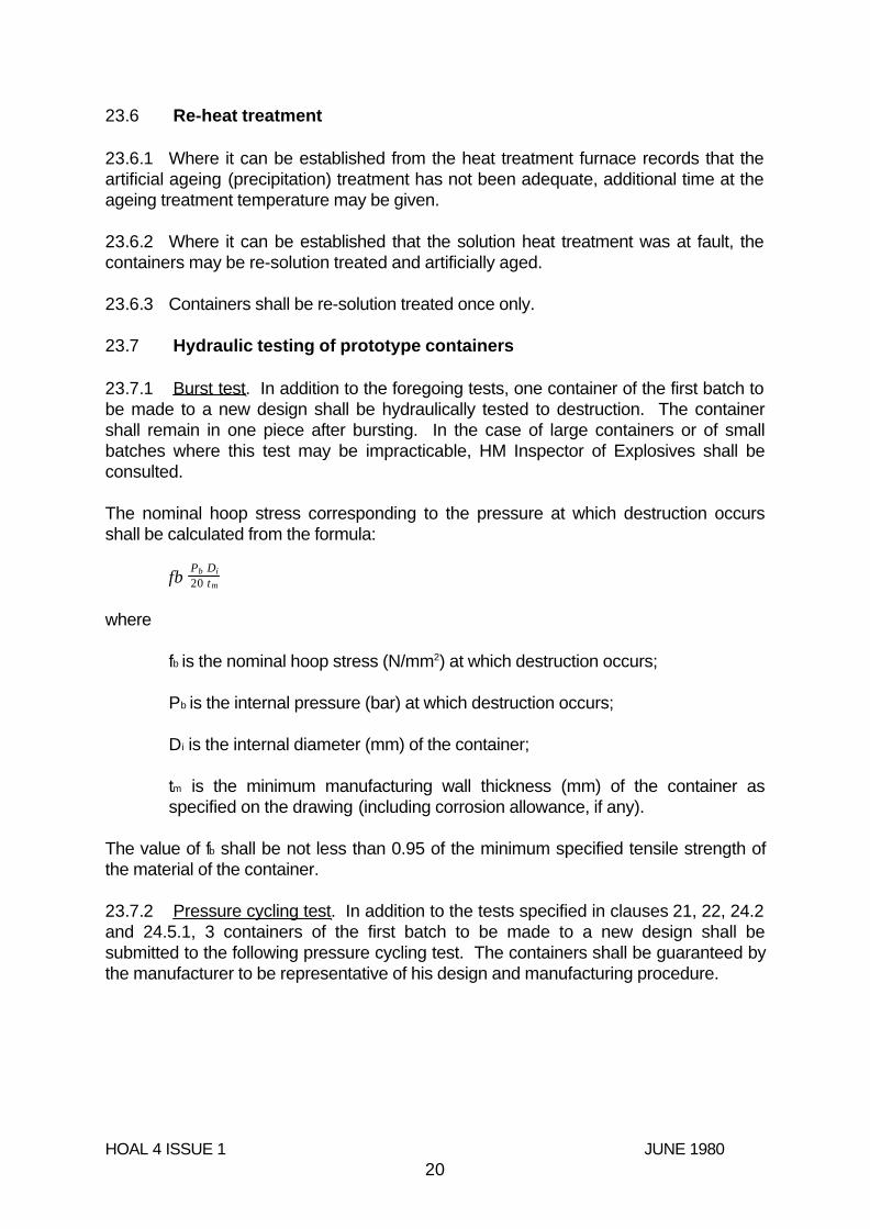
23.7.1 Burst test. In addition to the foregoing tests, one container of the first batch tobe made to a new design shall be hydraulically tested to destruction. The containershall remain in one piece after bursting. In the case of large containers or of smallbatches where this test may be impracticable, HM Inspector of Explosives shall beconsulted.
The nominal hoop stress corresponding to the pressure at which destruction occursshall be calculated from the formula:
fbPb Di20 tm
where
fb is the nominal hoop stress (N/mm2) at which destruction occurs;
Pb is the internal pressure (bar) at which destruction occurs;
Di is the internal diameter (mm) of the container;
tm is the minimum manufacturing wall thickness (mm) of the container asspecified on the drawing (including corrosion allowance, if any).
The value of fb shall be not less than 0.95 of the minimum specified tensile strength ofthe material of the container.
23.7.2 Pressure cycling test. In addition to the tests specified in clauses 21, 22, 24.2and 24.5.1, 3 containers of the first batch to be made to a new design shall besubmitted to the following pressure cycling test. The containers shall be guaranteed bythe manufacturer to be representative of his design and manufacturing procedure.
HOAL 4 ISSUE 1 JUNE 198020

23.7.2.1 The test shall be carried out using a non-corrosive fluid, with a range ofpressure equivalent to either 0.9 times the test pressure or 0.6 times the test pressureof the container. The value of the lower cyclic pressure shall not exceed 10% of theupper cyclic pressure. The frequency of reversals shall not exceed 15 cycles/min. Thetemperature measured on the outside surface of the containers shall not exceed 50°Cduring the test.
23.7.2.2 The containers shall be considered to have passed the test if theysatisfactorily complete:
either 10,000 cycles at 0.9 x test pressure; or
75,000 cycles at 0.6 x test pressure
without sign of leakage.
24. RESULTS OF TESTS
24.1 A record shall be kept of all tests made at the container maker’s works.
24.2 If any of the test specimens fail the mechanical tests, then:
if the Inspecting Authority considers that the failure was due to an error incarrying out the test, he may authorise a re-test and the first test shall beignored but, otherwise, at the manufacturers discretion, either:
(a) the mechanical test in which the failure occurred shall be repeatedon the container or test ring originally tested and in addition thetests under 22.3 and 22.4 shall be carried out on another containeror test ring from the same batch. If both containers or both testrings then comply with the test requirements of 22.3 and 22.4 thebatch may be accepted; or
(b) the batch may be re-heat treated as specified in 24.4.1 or 24.4.2and the mechanical tests called for under 22.3 and 22.4 shall becarried out. If the test rings then comply with the test requirements,the batch may be accepted.
24.3 If any of the mechanical tests required by 25.2(a) or (b) fail, the batch may bere-heat treated as specified in 24.4.1 or 24.4.2, as appropriate and re-tested asspecified in 25.2 and if the containers then comply with the test requirements the batchshall be accepted.
24.4 Not more than 2 containers or 2 test rings from one batch shall be submitted fortest and the limitations on re-heat treatments in 24.4.3 shall apply.
HOAL 4 ISSUE 1 JUNE 198021
24.5 If after the permitted number of re-tests and re-heat treatments the mechanicaltest requirements have not been complied with the containers in the batch shall berendered unserviceable for holding gas under pressure, by one of the followingmethods:
(a) the container shall be crushed by mechanical means;
(b) an irregular hole shall be burned in the top dome of the container,equivalent in area to approximately 10% of the area of the top dome; or,in the case of thin walled containers, the containers shall be pierced in atleast 3 places.
Any alternative method approved by HM Inspector of Explosives may be used instead.Drilling a hole in a container shall not be considered as satisfying the requirements ofthis clause.
25. MARKETING OF CONTAINERS
25.1 Each container which satisfies the requirements of this specification shall bepermanently and legibly marked with:
(a) the manufacturer’s mark and serial number;
(b) the test pressure in bars and date of the hydraulic test (which date maybe indicated by the month and year, or by the year with a symbol todenote the quarter of the year) and the identification mark of the personor firm who made the test;
(c) the identification mark(s) of the Independent Inspecting Authority;
(d) the specification to which the container was manufactured, ie HOAL 4;
(e) the charging pressure in bar at 15°C if the container is intended to beused for the conveyance of liquefiable gases;
(f) the minimum water capacity in litres of the container if it is intended tobe used for the conveyance of liquefiable gases;
(g) the tare in kg, ie the mass of the container and valve (excluding the valvecover) if it is intended for the conveyance of liquefiable gases;
(h) the mass in kg of the container only, if it is intended for the conveyanceof permanent gases.
25.2 The marks shall be on the neck end of the container with the exception of themanufacturer’s mark which may be on the base.
HOAL 4 ISSUE 1 JUNE 198022

25.3 The permanent marking shall not be made on the body of the container but shallbe at areas in the formed neck and base ends where the thickness of metal is greaterthan the design minimum and where it is adequate for marking to be carried out.
25.4 To verify the thickness of the metal at the ends of the container and the areassuitable for marking, a prototype container shall be sectioned at the ends and the areaswhere marking is permitted shall be agreed between the manufacturer and theIndependent Inspecting Authority.
25.5 A further prototype container shall be similarly sectioned and examined aftermarking. The marking shall cause no change in contour of the container. Thecharacters in the marking shall normally be at least 6 mm in height. On small containersthis height may be reduced but in no case shall the characters be less than 3 mm inheight.
25.6 When the conditions set out in 26.2 to 26.5 cannot be satisfied HM Inspectorsof Explosives shall be consulted.
HOAL 4 ISSUE 1 JUNE 198023
APPENDIX A - HYDRAULIC VOLUMETRIC EXPANSION TESTING OF GASCONTAINERS
A.1 General
This appendix described 2 methods, as follows, for determining the volumetricexpansion of seamless aluminium alloy gas containers as required by clause 24:
(a) the water-jacket method (preferred method);
(b) the non-water jacket method.
The water-jacket volumetric expansion test may be carried out on equipment using alevelling burette or a fixed burette.
A.2 Test equipment
The following requirements are common to both methods of test:
(a) hydraulic test pressure pipelines shall be capable of withstanding apressure twice the maximum test pressure of any container that may betested;
(b) glass burettes shall be of sufficient length to contain the full volumetricexpansion of the container and shall be capable of being read to anaccuracy to 1% or 0.1 ml;
(c) pressure gauges shall be manufactured and maintained in accordancewith BS 1780: Part 2 Industrial class 1. They shall be tested at regularintervals and in any case not less frequently than once per month;
(d) a suitable device shall be employed to ensure that no container issubjected to a pressure in excess of its test pressure;
(e) pipework should utilise long bends in preference to elbow fittings andpressure pipes should be as short as possible. Flexible tubing shall becapable of withstanding twice the maximum test pressure in theequipment and have sufficient wall thickness to prevent kinking;
(f) all joints should be leak-tight;
(g) when installing equipment, care shall be taken to avoid trapping of air inthe system.
HOAL 4 ISSUE 1 JUNE 198024

A.3 Water-jacket volumetric expansion test
The water-jacket volumetric expansion test necessitates enclosing the water-filledcontainer in a jacket also filled with water. The total and, if any, the permanentvolumetric expansion of the container are measured in relation to the amount of waterdisplaced by the expansion of the container when under pressure and after the pressureis released.
The water jacket should be fitted with a safety device capable of releasing the energyfrom any container that may burst at test pressure.
An air bleed valve should be fitted to the highest point of the jacket.
Two methods of performing this test are specified in A.3.1 and A.3.2. Other methodsare acceptable provided they are capable of measuring the total and, if any, thepermanent volumetric expansion of the container.
A.3.1 Water-jacket volumetric expansion test (levelling burette method)
The equipment should be installed as shown in figure 2.
Procedure
(a) Fill the container with water and attach to the water-jacket cover.
HOAL 4 ISSUE 1 JUNE 198025

HOAL 4 ISSUE 1 JUNE 198026

(b) Seal the container in the jacket and fill the jacket with water, allowing the air tobleed off through the air bleed valve.
(c) Connect the container to the pressure line. Adjust the burette to zero level bymanipulation of the jacket filling valve and drain valve. Raise the pressure totwo-thirds of the test pressure, stop pumping, and close the hydraulic pressuresupply valve.
NOTE: A rise in water level indicates a leaking joint between the container andthe jacket.
(d) Restart the pump and open the hydraulic pressure line valve until the containertest pressure is reached. Close the hydraulic pressure line valve and stoppumping.
(e) Lower the burette until the water level is at zero mark on the burette support.Take a reading of the water level in the burette. This reading is the totalexpansion and shall be recorded on the test certificate.
(f) Open the hydraulic line drain valve to release pressure from the container. Raisethe burette until the water level is at zero on the burette support. Check that thepressure is at zero and that the water level is constant.
(g) Read the water level in the burette. This reading is the permanent expansion, ifany, and shall be recorded on the test certificate.
(h) Check that the permanent expansion does not exceed 5% of the total expansionas determined by the following equation:
[ 5%permanent exp ansion x 100total exp ansion
A.3.2 Water-jacket volumetric expansion test (fixed burette method)
The equipment should be installed as shown in figure 3. The procedure for this methodof test is similar to that specified in A.3.1, except that the burette is fixed.
Procedure
(a) Adjust the water level to a datum. Apply pressure until the test pressure isreached and record the burette reading. The reading above the datum is the totalexpansion, and shall be recorded on the test certificate.
(b) Release the pressure and record the burette reading. The reading above thedatum, if any, is the permanent expansion, and shall be recorded on the test certificate.
HOAL 4 ISSUE 1 JUNE 198027

(c) Check that the permanent expansion does not exceed 5% of the total expansionas determined by the following equation:
[ 5%permanent exp ansion x 100total exp ansion
HOAL 4 ISSUE 1 JUNE 198028

HOAL 4 ISSUE 1 JUNE 198029

A.4 Non-water jacket volumetric expansion test
The non-water-jacket volumetric expansion test consists of measuring the amount ofwater passed into the container under proof pressure and, on release of this pressure,measuring the water returned to the manometer. It is necessary to allow for thecompressibility of water and for the volume of the container under test to obtain truevolumetric expansion. No fall in pressure during this test is permitted.
The water used should be free of air. Any leakage from the system or the presence offree or dissolved air will result in false readings.
The equipment should be installed as shown in figure 4. The figure illustrateddiagrammatically the different parts of the apparatus. The water supply pipe should beconnected to an overhead tank as shown, or to some other supply giving a sufficienthead of water.
A.4.1 Requirements for testing
The apparatus shall be so arranged that all air can be removed and accurate readingscan be obtained both of the volume of water required to pressurise the filled containerand of the volume expelled from the container when depressurised. In the case of largercontainers, it may be necessary to augment the glass tube with metal tubes arranged ina manifold.
If a single acting hydraulic pump is used, care shall be taken to ensure that the piston isin the ‘back’ position when water levels are noted.
A.4.2 Test method
Proceed as follows:
(a) completely fill the container with water and determine the mass of waterrequired;
(b) connect the container to the hydraulic test pump through coil A and checkthat all valves are closed;
(c) fill the pump and system with water from tank C by opening valves D, Eand H;
(d) to ensure the expulsion of air from the system, close valve H and raise thesystem pressure to approximately one-third of the test pressure. Openbleed valve G to release trapped air by reducing the system pressure tozero, and reclose valve G. Repeat if necessary;
HOAL 4 ISSUE 1 JUNE 198030
(e) continue to fill the system until the level in glass tube M is approximately300 mm from the top of this tube. Close valve D and mark the water levelby pointer P, leaving valves E and H open. Record the level;
(f) close valve H. Raise the pressure in the system until pressure gauge(s)records the required test pressure. Stop the pump. After approximately30 s there should be no change in either the water level or the pressure.A change in level indicates leakage. A fall in pressure, if there is noleakage, indicates that the cylinder is still expanding under pressure.
(g) record the fall of the water level in the glass tube. Providing there hasbeen no leakage, the water drained from the glass tube will have beenpumped into the container to achieve test pressure. This difference inwater level is the volumetric expansion;
(h) open valve H slowly to release the pressure in the container and allow thewater so released to return to the glass tube. The water level shouldreturn to the original level marked by pointer P. If the water level returns toa point below pointer P, this difference in level will denote the amount ofpermanent volumetric expansion in the container, neglecting the effect ofthe compressibility of the water at test pressure. The true permanentvolumetric expansion of the container is obtained by correcting for thecompressibility of the water obtained from the calculation given in A.4.4;
(i) before disconnecting the container from the test rig, close valve E. Thiswill leave the pump and system full of water for the next test. Action (d)shall, however, be repeated at each subsequent test;
(j) if permanent volumetric expansion has occurred, record the temperatureof the water in the container.
A.4.3 Test results
A.4.3.1 The tests determine the volume of water required to pressurise the filledcontainer to test pressure.
A.4.3.2 The total mass and temperature of the water in the container are known,enabling change in the volume of the water in the container due to itscompressibility to be calculated. The volume of water expelled from thecontainer when depressurised is known. Thus total volumetric expansion (TE)and permanent volumetric expansion (PE) can be determined.
A.4.3.3 The permanent volumetric expansion shall not exceed 5% of the totalvolumetric expansion.
A.4.4 Calculation of the compressibility of water
The formula used for the calculation of the compressibility of water is as follows:
HOAL 4 ISSUE 1 JUNE 198031

C = mP K − 0.68P10 5
where:
C is the compressibility (in ml)
m is the mass of water (in kg)
P is the test pressure (in bar)
K is the factor for individual temperatures as given in Table 3.
Table 3 - K factors for the compressibility of water
0.04594260.04668190.0477512
0.04604250.04680180.0479211
0.04613240.04695170.0481210
0.04623230.04710160.048349
0.04633220.04725150.048608
0.04643210.04742140.048867
0.04654200.04759130.049156
K°CK°CK°C
A.4.5 Example calculation
In the following example calculation, allowance for pipe stretch has been neglected.
Example:
15°C=Temperature of water
113.8 kg=Mass of water in container at zero gauge pressure
232 bar gauge=Test pressure
HOAL 4 ISSUE 1 JUNE 198032

% PE = = 0.58%3 x 100520.7
Total volumetric expansion (TE) = 1745 - 1224.3 = 520.7 ml
1,224.31== 115.545 x 232 (0.04725 - )0.68 x 232105
C = mp K −0.68p‘105
0.04725=From Table 3 K factor for 15°C
3 ml=Permanent expansion (PE) = 1745 - 1742
1742 ml=Water expelled from container to depressurise
115.545 kg=Total mass of water (m) in container at 232 bar = 113.8 + 1.745
1745 ml (or 1.745 kg)=Water forced into container to raise pressure to 232 bar
HOAL 4 ISSUE 1 JUNE 198033

APPENDIX B - EXAMPLES OF DESIGN CALCULATIONS FOR CYLINDRICALWALLS OF SEAMLESS CONTAINERS
B.1 Container for permanent gas
A container having an external diameter of 176 mm, made from aluminium alloy to thechemical composition given in Table 1, is to be filled with oxygen to a pressure (at theequilibrium temperature of 15°C) not exceeding 136.5 bar gauge.
Determination of developed pressure at reference temperature
From 12.2 the reference temperature for permanent gas is 60°C for theUnited Kingdom.
From BS 5355 the developed pressure p, at 60°C for oxygen filled to 136.5 bar is166 bar.
Calculation of test pressure
From 15.2 P1 = 1.34 x 166 = 222 bar.
Minimum thickness of cylindrical wall
Equation (1) of 15.3 gives t = 0.3 P 1 DO7fe − 0.4 P 1
where:
P1 = 222 bar
DO = 176 mm
Fe = 206 N/mm2 from 15.1
Thus t = = 8.66 mm0.3 x 222 x 176(7 x 206) − (0.4 x 222)
However, the thickness of the cylindrical wall shall not be less than the value given byequation (2) of 15.3
t = 2.48 = 2.48 = 1.73 mmDiT
158.7325
As this thickness does not exceed the value obtained by calculation from equation (1) of15.3, the required minimum thickness is 8.66 mm.
HOAL 4 ISSUE 1 JUNE 198034

B.2 Container for high pressure liquefiable gas
A container having an external diameter of 152 mm is to be manufactured fromaluminium alloy to the composition given in Table 1, have a water capacity of 8.0 litresand be suitable for use with carbon dioxide for dispensing soft drinks.
Determination of developed pressure at reference temperature
From 12.2 the reference temperature for carbon dioxide is 50°C when a safety deviceis fitted.
From BS 5355 the developed pressure, p, at 50°C for carbon dioxide used forpurposes other than fire extinguishing (ie a filling ratio of 0.75) is 174.51 bar.
Calculation of test pressure
From 15.2 P1 = 1.21 x 174.51 = 211 bar
Minimum thickness of cylindrical shell
Equation (1) of 15.3 gives t = 0.3 P 1 Do7fe − 0.4 P 1
where:
P1 = 211 bar
DO = 152 mm
fe = 206 N/mm2 from 15.1
Thus t = = 7.08 mm0.3 x 211 x 152(7 x 206) − (0.4 x 211)
However, the thickness of the cylindrical wall shall not be less than the value given byequation (2) of 15.3
t = 2.48 = 2.48 = 1.61 mmDiT
137.8325
As this thickness does not exceed the value obtained by calculation from equation (1) of15.3, the required minimum wall thickness is 7.08 mm.
HOAL 4 ISSUE 1 JUNE 198035

APPENDIX C - SPECIMEN CERTIFICATES FOR SEAMLESS ALUMINIUM ALLOYGAS CONTAINERS
C.1 Specimen acceptance certificate for seamless aluminium alloy gascontainers
Certificate number ....................
We certify that containers manufactured to Specification HOAL 4
Drawing number ................................................ Against order number .............
For: CustomerAddress
Conform to the following requirements
1. Minimum wall thickness. The minimum wall thickness has been measured
by inspection personnel to a minimum of ...... mm for all containers.
2. Minimum hardness value. All containers have been checked to satisfy the
minimum hardness value of ...... .
3. Heat treatment. Each container had been treated between 520°C and 540°C
followed by water quenching, and artificially aged between 160°C and 190°C followed
by air cooling to give the properties required in 11.2 of HOAL 4.
4. Hydraulic pressure test. Each container has been subjected to a hydraulic
pressure test of ...... bar.
The total volumetric expansions at test pressure were within the range ........ to ........ ml.
The permanent volumetric expansions as a percentage of the total volumetric expansion
were within the range ........ to ........ %.
5. Material. All containers have been manufactured from material conforming in
chemical analysis to Table 1 of HOAL 4. The cast numbers used were ...............
.................................. .
HOAL 4 ISSUE 1 JUNE 198036

6. Tare and capacities are within the limits stated:
Tare .............................
Capacity .......................
The test report numbers are ...............................................
The containers covered by the above certification are serial
numbers .....................................................
Date:
Signature: Signature:
Chief Inspector Independent Inspecting Authority
HOAL 4 ISSUE 1 JUNE 198037
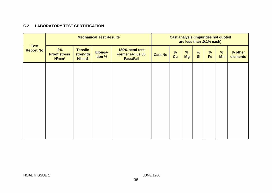
C.2 LABORATORY TEST CERTIFICATION
% otherelements
%Mn
%Fe
%Si
%Mg
%CuCast No
180% bend testFormer radius 35
Pass/Fail
Elonga-tion %
TensilestrengthN/mm2
.2%Proof stress
N/mm2
Cast analysis (impurities not quotedare less than .0.1% each)
Mechanical Test Results
TestReport No
HOAL 4 ISSUE 1 JUNE 198038

APPENDIX D - APPROVED METHOD OF COATING COPPER BASED ALLOYSFOR SERVICE WITH ALUMINIUM ALLOY CONTAINERS
D.1 Flash of electrotin internally and externally
D.2 Cadmium plating of 0.010/0.025 mm on the body stem thread
D.3 Cadmium plating to 0.008 mm on all other internal and external parts ofthe valve body
D.4 Passivate in accordance with the following procedure:
(a) Surface preparation
(1) Degreasing - freshly plated or heat treated components do not requiredegreasing. Otherwise degrease in trichloroethylene.
(2) Cleaning - freshly plated or heat treated components do not requirecleaning. Otherwise immerse for 5 min - 15 min in a boiling solutioncontaining 100 g - 200 g trisodium phosphate per litre of water.
(3) Washing - wash in cold running water to remove all electrolyte or cleaningsolution. Allow to drain, immediately before passivation, immerse for notmore than 10 s in a weak solution of nitric or sulphuric acid containing notmore than 1 ml/litre concentration.
(b) Passivation
Immerse for 5 s - 10 s in either of the following solutions at roomtemperature:
200 - 250 g/litre of waterchromic acid
25 - 30 g/litre of wateranhydrous sodium sulphate
or
6 - 10 ml/litre of watersulphuric acid (sg 1.84)
150 - 200 g/litre of watersodium dichromate crystals
(c) Final washing and drying
(1) Transfer immediately to a tank of cold running water for a few seconds.
(2) Transfer to a second tank of cold running water for approximatelyone minute.
HOAL 4 ISSUE 1 JUNE 198039

(3) Warm water insertion up to 50°C for 30 s maximum is permissible toassist drying.
(4) Dry in circulating air at a maximum temperature of 50°C.
HOAL 4 ISSUE 1 JUNE 198040
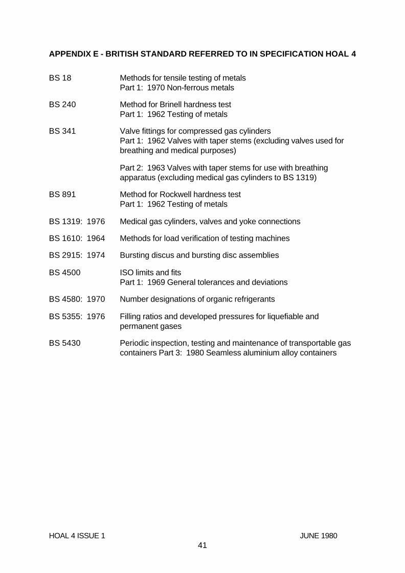
APPENDIX E - BRITISH STANDARD REFERRED TO IN SPECIFICATION HOAL 4
Periodic inspection, testing and maintenance of transportable gascontainers Part 3: 1980 Seamless aluminium alloy containers
BS 5430
Filling ratios and developed pressures for liquefiable andpermanent gases
BS 5355: 1976
Number designations of organic refrigerantsBS 4580: 1970
ISO limits and fitsPart 1: 1969 General tolerances and deviations
BS 4500
Bursting discus and bursting disc assembliesBS 2915: 1974
Methods for load verification of testing machinesBS 1610: 1964
Medical gas cylinders, valves and yoke connectionsBS 1319: 1976
Method for Rockwell hardness testPart 1: 1962 Testing of metals
BS 891
Part 2: 1963 Valves with taper stems for use with breathingapparatus (excluding medical gas cylinders to BS 1319)
Valve fittings for compressed gas cylindersPart 1: 1962 Valves with taper stems (excluding valves used forbreathing and medical purposes)
BS 341
Method for Brinell hardness testPart 1: 1962 Testing of metals
BS 240
Methods for tensile testing of metalsPart 1: 1970 Non-ferrous metals
BS 18
HOAL 4 ISSUE 1 JUNE 198041