Embed Size (px)
Citation preview

Southeast Regional Carbon Sequestration Partnership: Regional
Sequestration Capacity
Presented by:
Ian Duncan Associate Director
Bureau of Economic GeologyJackson School of Geological Sciences
University of Texas at Austin

Gulf Coast Carbon Center (GCCC)
Sponsors


THE US IS THE SAUDI ARABIA OF COAL
What are the Implications for the Oil Industry
• High oil prices and National Security will drive gasification of coal and production of synthetic diesel for DOD
• Environmental NGO’s driving power companies to decarbonize fuel…. CO2 sequestration
• Cheap CO2 available for EOR


Denbury EOR
Existing Denbury pipelinesPlanned Denbury pipelines
Denbury Sources
Jackson Dome- Earliest sourceof CO2-
Cranfield earliest largeVolume saline injection
Selecting the early large volume storage site in the SECARB region

Saline Aquifers - Deep Portions of Geologic Units with High TDS
WaterSink requirements:1. Dense CO2 (Deeper than 800m
(2600 ft) under normal T & P gradient.
2. Porous and permeable unit of known geometry.
3. Integrity of overlying seal.
4. Below underground sources of drinking water (USDW), water greater than 10,000 mg/L total dissolved solids (TDS).
Freshwater aquifer
AtmosphereBiosphere
Vadose zone & soil
Seal
Seal
CO2 plume

Optimizing CO2 Storage
20
25
30
35
40
45
50
0 5,000 10,000 15,000Depth (ft)
CO
2bu
lk v
olum
e re
sidu
al
(kgm
/m3 ) Maximum storage
capacity

Schematic Cross Section Appalachian Plateau to Coastal Plain
Source: Miller (1990), Groundwater Atlas of the United States: Alabama, Florida, Georgia, and South Carolina

Deep River Basin in North Carolina
Source: Luongo (1987) Va. Tech Thesis, Figure 17 – interpretation based on seismic data
A
A’
Source: Thayer (2006)
EXPOSED TRIASSIC BASINSLOW POTENTIAL
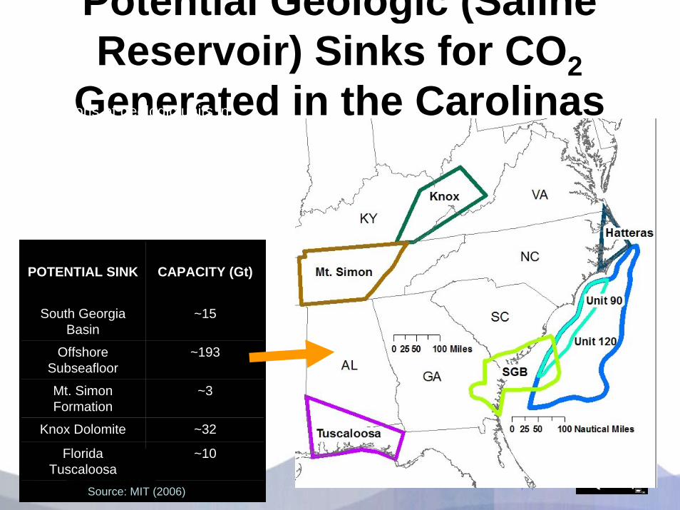
Potential Geologic (Saline Reservoir) Sinks for CO2
Generated in the CarolinasLocations of geologic units in which subsurface saline aquifers (i.e. potential geologic sinks) are found.
Sinks chosen on the basis of geologic suitability alone..…
POTENTIAL SINK CAPACITY (Gt)
South Georgia Basin
~15
Offshore Subseafloor
~193
Mt. Simon Formation
~3
Knox Dolomite ~32
Florida Tuscaloosa
~10
Source: MIT (2006)

Seismic Line Offshore Cape Fear, NC
Modified from Grow et al. (1988); Hutchinson et al. (1982); and Hutchinson et al. (1997)

CO2 Storage - SE Atlantic CoastAppalachian PlateauHIGH POTENTIAL
Valley and Ridge
LOW POTENTIAL
Blue RidgeLOW POTENTIAL
Piedmont
LOW POTENTIAL
Exposed Rift BasinsLOW POTENTIAL
Coastal PlainHIGH POTENTIAL
Offshore SubseafloorHIGH POTENTIAL
Modified from Fenneman and Johnson (1946); NOAA (2006); Scripps (2006) ; and Olsen et al. (1991).

Gulf wedge is the most significant sequestration target in the Southeast
200 billion tons plusOther sequestration targets in the Southeast lack seals and storage volume
Regional Opportunities for Deep Saline StorageRegional Opportunities for Deep Saline Storage

Lower Tuscaloosa Fm Massive Sand
Unit
Lower Tuscaloosa Fm Massive Sand
Unit
LowerTuscaloosa Equivalent
Sandstones
LowerTuscaloosa Equivalent
Sandstones
SabineUplift
SabineUplift
PlantDaniel
CranfieldOil Field
The Lower Tuscaloosa Massive Sand Unit and The Lower Tuscaloosa Massive Sand Unit and Mississippi Test Site LocationsMississippi Test Site Locations

Line of section

CO2-EOR Candidate Reservoirs – Key Element in the Gulf CoastCO2-EOR Candidate Reservoirs – Key Element in the Gulf Coast


Looking at Miscible EOR from a Production Standpoint
98 89
1,500
3,027
4,714
0
500
1,000
1,500
2,000
2,500
3,000
3,500
4,000
4,500
5,000
Oil
EOR
Pot
entia
l (M
illio
n B
arre
ls)
Alabama Mississippi Louisiana Texas GulfCoast
Total
New Miscible CO2 EOR Potential
Mark Holtz, GCCC

Converting CO2-EOR to Storage
• Permanently store CO2 in reservoir after
EOR has been completed
• Reservoir characterization and
simulation for long–term storage
• Long–term measurement, monitoring,
and verification (MMV) systems.

Storage Capacity associated with CO2 EOR
87 115
1,1141,362
2,679
0
500
1,000
1,500
2,000
2,500
3,000
CO
2 St
orag
e C
apac
ity
(Mill
ion
Met
ric T
ons)
Mississippi Alabama Louisiana Texas GulfCoast
Total
New CO2 Storage Capacity

CO2 EOR Is not “The Answer” …
• Volume of CO2 that could be sold for EOR is large but inadequate to solve the GHG issue (1 to 2 billion tons of storage)
• CO2 EOR is useful only in areas oil production, and is most useful only in certain reservoirs with lighter oil, moderate depth, unitized, with reasonable sweep efficiency.

…but CO2 EOR is a great beginning
• Economic or near economic in current market, depending on cost of CO2
• Acceptable to public • Other major benefits (domestic energy
production, taxes, employment)• Build infrastructure that can be used long
term for large volume CO2 disposal = stacked storage

Mississippi Test SiteMississippi Power’s Plant Daniel
near Escatawpa, Mississippi
Coal Seam Projectnear Tuscaloosa, Alabama
Coal Seam Projectsite selection pending
Stacked Storage ProjectCranfield Test Site
Southwest Mississippi
SECARB Phase II Geographic Region & SECARB Phase II Geographic Region & Field Test Site LocationsField Test Site Locations

Lower Tuscaloosa Massive Sand Unit (U. Cretaceous)Dantzler (Washita-Fredricksburg) Formation (L. Cretaceous)
Potential CO2 Storage Units:
Confining Units (Seals):Midway ShaleSelma Chalk/Navarro Fm.Austin Formation (Fm.)Marine Tuscaloosa
System
Series
StratigraphicUnit Sub-Units Hydrology
Navarro Fm.
Selma ChalkTaylor Fm.
Confining unitConfining unit
Austin Fm. Confining unitConfining unitEutaw
Eagle Ford Fm. Saline ReservoirSaline Reservoir
Upper Tusc.
Marine Tusc. Confining unitConfining unit
Upper
TuscaloosaGroup
LowerTusc. Saline ReservoirSaline Reservoir
Dantzler Fm. Saline ReservoirSaline Reservoir
Cretaceous
Lower
Washita –Fredricksburg “Limestone Unit”
Minor ReservoirMinor Reservoir
Interbeds
Massive Sand
Misc. MioceneUnits
Tertiary
Miocene
FreshwaterAquifers
FreshwaterAquifers
Pascagoula Fm.Hattiesburg Fm.Catahoula Fm.
Vicksburg
JacksonClaiborne
Wilcox
Midway Shale
Minor ReservoirMinor Reservoir
Confining unitConfining unit
Saline ReservoirSaline ReservoirSaline ReservoirSaline Reservoir
Saline ReservoirSaline Reservoir
Saline ReservoirSaline Reservoir
Oligo-cene
EocenePaleo-cene
Red Bluff Fm.
Plio-cene Citronelle Fm.
Graham Ferry Fm.Freshwater
AquifersFreshwater
Aquifers
Injection Zone
Confining Zone
AdditionalConfining Zones
Saline Reservoir Units and Seals Saline Reservoir Units and Seals (Southeast Mississippi)(Southeast Mississippi)

FT1
Field Test 1.0: Cranfield Site
Stacked Storage ProjectStacked Storage Project

Field Test 2.0: Kentucky, Virginia and West Virginia
FT2aCoal Seam Sequestration OpportunitiesCoal Seam Sequestration Opportunities

Field Test 2.0: Black Warrior Basin, Alabama FT2b
Coal Seam Sequestration OpportunitiesCoal Seam Sequestration Opportunities

LEARNING BY DOING
• MMV (Monitoring, Mitigation, Verification)• Economic Modeling • Permitting• Liability, Ownership Issues

Aims of MMV
• Protect public health and safety• Confirmation of the integrity of
engineered saline reservoirs• Providing verification of long term
storage volumes for CO2 credits• Provide direct tangible evidence for
predicting the long term risk of leakage
• Ensure public acceptance

• Atmosphere– Ultimate receptor but dynamic
• Biosphere– Assurance of no damage but
dynamic• Soil and Vadose Zone
– Integrator but dynamic• Aquifer and USDW
– Integrator, slightly isolated from ecological effects
• Above injection monitoring zone– First indicator, monitor small
signals, stable. • In injection zone - plume
– Oil-field type technologies. Will not identify small leaks
• In injection zone - outside plume– Assure lateral migration of CO2
and brine is acceptable-far field pressure
Aquifer and USDW
AtmosphereBiosphere
Vadose zone & soil
Seal
Seal
CO2 plume
Monitoring Zone
Monitoring ZonesMonitoring Zones

MEASUREMENT MONITORING AND
VERIFICATION at the Bureau of Economic Geology’s FRIO Pilot
Injection Site
Research Funded byDOE NETL and Gulf Coast carbon Center

Frio Brine Pilot Research Team• Bureau of Economic Geology, Jackson School, The University of Texas at
Austin: Susan Hovorka, Mark Holtz, Shinichi Sakurai, Seay Nance, Joseph Yeh, Paul Knox, Khaled Faoud, Jeff Paine
• Lawrence Berkeley National Lab, (Geo-Seq): Larry Myer, Tom Daley, Barry Freifeld, Rob Trautz, Christine Doughty, Sally Benson, Karsten Pruess, Curt Oldenburg, Jennifer Lewicki, Ernie Majer, Mike Hoversten, Mac Kennedy, Paul Cook
• Schlumberger: T. S. Ramakrishna, Nadja Mueller, Austin Boyd, Mike Wilt• Oak Ridge National Lab: Dave Cole, Tommy Phelps, David Riestberg• Lawrence Livermore National Lab: Kevin Knauss, Jim Johnson• Alberta Research Council: Bill Gunter, John Robinson, Bernice Kadatz• Texas American Resources: Don Charbula, David Hargiss• Sandia Technologies: Dan Collins, “Spud” Miller, David Freeman; Phil Papadeas• BP: Charles Christopher, Mike Chambers• SEQURE – National Energy Technology Lab: Curt White, Rod Diehl, Grant
Bromhall, Brian Stratizar, Art Wells • Paulsson Geophysical – Bjorn Paulsson• University of West Virginia: Henry Rausch• USGS: Yousif Kharaka, Bill Evans, Evangelos Kakauros, Jim Thorsen• Praxair: Joe Shine, Dan Dalton• Australian CO2CRC (CSIRO): Kevin Dodds, Don Sherlock• Core Labs: Paul Martin and others

Frio Brine Pilot Site
• Injection interval: 24-m-thick, mineralogically complex Oligocene reworked fluvial sandstone, porosity 24%, Permeability 2.5 Darcys
• Unusually homogeneous• Steeply dipping 16 degrees• 7m perforated zone• Seals − numerous thick shales,
small fault block• Depth 1,500 m• Brine-rock system, no
hydrocarbons• 150 bar, 53 degrees C,
supercritical CO2
Injection interval
Oil production

Injection Well
Observation Well
Closely spacedmeasurementsin time and space

New tool to do the job:
LBNL U-tube
instrument to collect high frequency,high quality two-phase samples
Tommy PhelpsDave Ristenburg Oak Ridge National Lab
Seay Nance BEG

CO2 Saturation Observed with Cross-well Seismic Tomography
vs. Modeled
Tom Daley and Christine Doughty LBNL

Rapid Dissolution of CO2 in Field Tests – a significant factor in
reducing plume size Frio CO2 injection (Oct. 4-7/04)
5.5
6.0
6.5
7.0
4-Oct-04 5-Oct-04 6-Oct-04 7-Oct-04 8-Oct-04
Time
pH
1
10
100
1000
10000
Fe (m
g/L)
pHFe
Yousif Kahraka USGS
Within 2 days, CO2 has dissolved into brine and pH falls, dissolving Fe and Mn

WHAT WE LEARNED
• Monitoring injection of CO2 into relatively homogenous high permeability sandstone confirms validity of our numerical models
• Tools are available off-the-shelf for effective MMV

CONCLUSIONS• Gulf Coast has largest sequestration
capacity in US co-located with major
concentration of CO2 emissions
• Florida has moderate potential for
Sequestration
• Atlantic coast states have poor potential
except offshore

Southeast Regional Carbon Sequestration Partnership
Gerald R. Hill, Ph.D. SECARB Technical Coordinator
Southern States Energy Board6325 Amherst Court
Norcross, Georgia 30092 USAPhone: (770) 242-7712
Fax: (770) 242-0421www.sseb.org
www.secarbon.org