Embed Size (px)
Citation preview
C.P. No. 951
MINISTRY OF TECHNOLOGY
AERONAUTICAL RESEARCH COUNClL
CURRENT PAPERS
Some Theoretical StudiesConcerning Oleo Damping
Characteristics
LONDON: HER MAJESTY’S STATIONERY OFFICE
1967
PRICE 6s 6d NET

U.D.C. No. 6zg.lj.ov.563 : 62g.?j.o15.11 : 533.6.0~3.423
C.P. No.951*
October 1966
The paper presents results o? a study that has been made to investigatethe effect of dsmping characteristics on the performance of an oleo strut.Conventional oleo struts employ orifice dampers in the interests of providinghigh energy absorption for the design vertical velocity of descent case. It is
ahown that an equivalent strut i.e. one having the same maximum stroke,utilizing a dsmping mechanism providing a force proportional to the strokingvelocity, instead of the square of this velocity, will benefit by a IO per centreduction in stress in the design case. Comparison of the performance of thesetwo types of damper in the taxi phase of operation over a real pirofile showsthat a linear' damper has better characteristics then an 'orifice' damper havingthe same damping constant in capression and recoil.
*Replaces K .L.X. Tech. Report No.66312 - L.R.C. 28YO5.

2
COx?3i~ s
1 mE?oDmrIoN2 C~w~~IOPrS3 rnSLLTS
301 Landing operation3-2 Taxying operation
3.2.1 Discrete (l-cosine) 'hnqx3.2.2 2unway profile
4 TX2 USIGN OF k lJXE.Aa D.!XEZi?5 C4mCLUSIONS6 fxxlTo~;~m~,~m sTable 1 The velocities and kinetic energies at tQ&i-amm,
recoil and reboundR&erencesIllustrationsI)etachable abstract cards
Page3466889
IO12
13I !i

1 INTRODUCl!IclN
Over the past few years there has been an increase in undercarriagefailures which has emphasised the need to design future undercarriages withlonger fatigue lives. As a result, interest in fundamental design principleshas been renewed. The present paper examirms some of the consequences thatstem from one of the significant parameters in undercarriage design, namelythat of oleo damping. It presents the results of some calculations made toccmpsre the performance of an undercarriage when the oleo damping characteristicsare the conventional square law and when they are linear with stroking velocity.
The adoption of square law damping devices seems to have came aboutbecause of the fact that the pressure difference associated with theflo+v through an orifice prodru3es a high resistance and consequently a pm{erfuldamping fcrce that can easily be utilized to provide a practical design. Byvirtue of the fact that the orifice is small the Jet velocities and ReynoldrsNumbers are high and fully turbulent flow is developed so that the dampingforoe is proportional to the square of stroking velocity. In practical orificedesign the peak flow velocity in the orifice may, on occasions, be so high thatthe possibility of transonio flo;v and 'choking' must be considered+ As manyundercarriages are designed to satisfy the energy absorption required at designlanding veiocity, damping is a maximum at the corresponding relatively highstroking velocities. A strut designed by these considerations will have lowdamping oapacity at the low stroking velocities that occur in the taxi phaseof operation.
An alternative method of providing d3mping can be conceived. A flinearldamper in which the damping force is directly proportionalto stroking velocity.Using this method adequate damping capacity may be provided in both thelanding and taxi phase of operation. There should not be the rapid fall-off inefficiency of such a damper at low stroke velocities that occurs with theorifice damper. The realization of such a damper in practice will lead todesign problems and these are considered in the text.
Possible methods of constructing a linear damper are discussed inSection 4. In Sections 3.1 and 3.2 limited ccrmparisons arc made betiyeen theperformance of a strut having linear and orifice damping characteristics inboth the landing and taxying phase of the aircraft operation.

2 CJ~TICp$S
The strut hav% linear damping ch~acteristics was designed to a heavylanding case. The appropriate touch-down velocity being 8.86 ft/ses.
The mathematical model on v;hich the calculations v/we based is shoiln inFig.1. The shock strut axis was considered to be in the vertical planethroughout. It consisted of an usFer mass representing the aircraft connectedthrough an air spring and damper in parallel with the loser mass representingthe wheel assembly, which -<{as supported on the tyre spring. For all thelanding cases ccnsidered there was assumed to be a lift force present whichwas equal to the dropping weight. During the taxi runs considered in thispaper the lift -<fas assumed to be zero. The effect of strut friction ;;ras notconsidered in any of the calculations made.
In the first of the landing calculations i.e. at 8.86 ft/sec the mostaccurate reJ3resentation of the strut propcrtitis that was available wasutilized. This meant for both struts polytropic air springing and exponentialtyre characteristics were considered. The characteristics of the air springwere represented by -
'a = pa Aa0
and the tyres by -
where F
p:
is the pneumatic forcethe air pressure in the upper &am&r for the fully extended strut
0
Aa the pneumatic area
vOthe air volume for the fully extended strut
S the stroken the effective polytropic exponentF-2
the vertical force applied to the tyrc at the ground
z2 the vertical displacement of the lower mass from the position atthe initial contact
a thz overall diameter of the tyreand at :iid r constants with different values for the mrims regimes of thetyrc deflection process.
7
is some IO per cent greater than that for the linear d,amper. The peak isreached sooner in the stroke in the linear case.
It should be mentioned that in the American Paper' no information isgiven on the damping constant that is appropriate to the recoil stroke. InRef.1 the concern was with the peak load generated and this occurs as we haveseen in Fig.3 prior to the maximum stroke being achieved. In the first placetherefare the recoil damping constant was taken to be equal to that onccmpression. Other calculations were made to investigate variations in thisparameter and although such variations were arbitrary, the results indicatewhat may occur with a practical strut design.
Figs.4 and 5 show the strut force obtained in three cases, which may beoonsidered to represent a normal, moderately heavy and severe landing caserespectively. For the purpose of these and subsequent calculations, the tyreforces were taken to vary linearly with displacement. It has been mentionedabove that this approximation introduced little error at a particular touch-downvelocity. In view of this it was considered that efforts to obtain true tyrecharacteristics appropriate to other velocities was unwarranted. The figuresshwthat-
(a) For the normal landing the orifice damper develops smaller peakload than the linear, but at the expense of a longer stroke.
(b) For the moderately heavy landing there is little to choose betweenthe two dampers in terms of either peak load or strda.
(a) For the severe landing the linear damper gives lower peak force,the maximum stroke being the sam e in both cases, and the curve of strut forceagainst stroke is much nearer to the ideal step form.
The effect of increasing damping on the recoil stroke far the orifice damperis shuwn in Fig.4. It is to give a sharper out-off to the strut force, oncethe peak strut deflection has been reached. Table 1 gives details of thevelocities and kinetic energies at the instant of touch-dam, rzooil andrebound. In the Table 2, andfi2 are the velocities of the upper (sprung) andlower (unsprung) masses respectively. Recoil is defined as the instant atwhioh the strut action changes from ccanpression to extension. Rebound thatat which the tyre leaves the ground, and the kinetic energy that due to motionof the upper and lower masses. It can be seen that in general the orificedamper will dissipate more energy over the interval - touch-down to rebound,
8
cs$ecinlly if a strut viith a high recoil damping coefficient is considered.For the sev3rr2 landing case more energy is absorbed in the com;3ression strokefor the linear damper, but conversely more is given back in the rebound strokethan for the orifice damper with high recoil damping. At lower doscentvelocities less energy is absorbed by the linear damper in the compressionstroke but the relative amount of energy fed back in the extension stroke isa function of both damper type and velocity. An interesting point emergesfrom these results, that for orifice dampers the effect of increased recoildamping is a progressively decreasing one, measured in terms of kineticenergy still present at rebound, as the touch-down velocity increases.
3.2 Taxying operation
3.2.1 Discrete (l-cosine) bumps
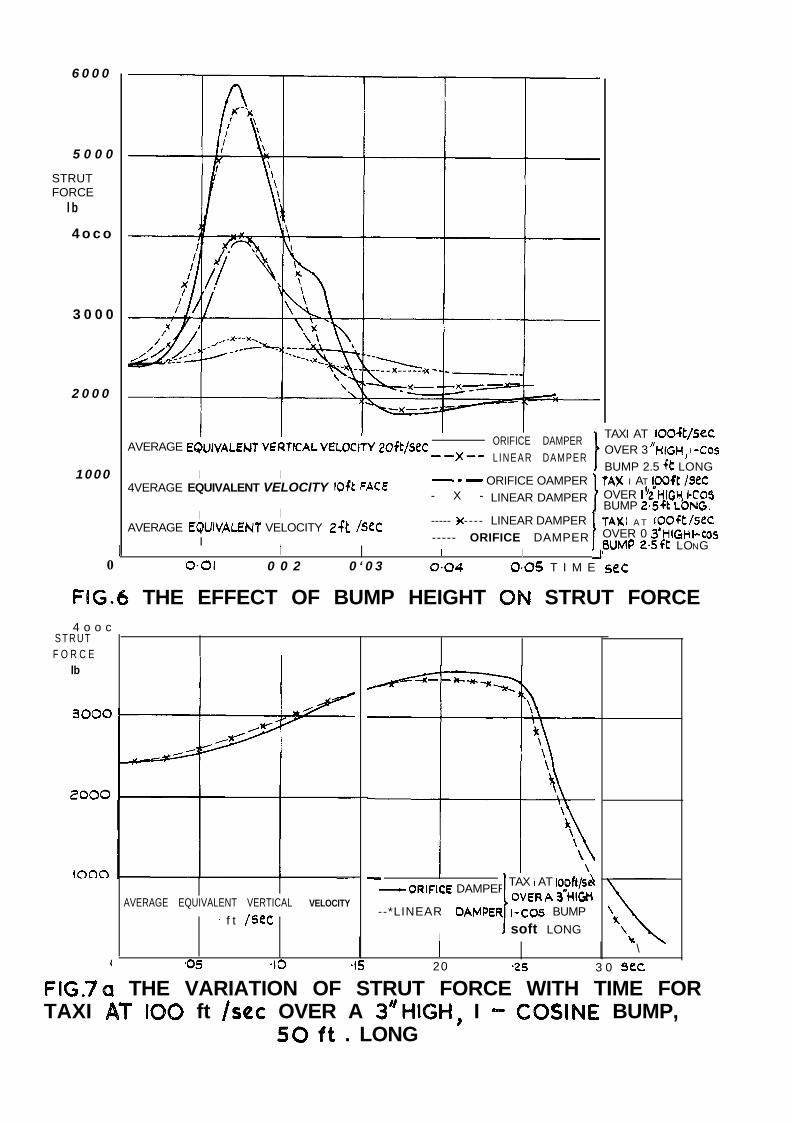
The results are shown in Figs.6 to 8 and are all concerned with the strutforce developed on passage over various bumps. Fig.6 shows the effect oftaxying at a particular speed over three bumps, 0.3 in, 1s in and 3 in high.These results show that generally the maximum force is produced slightly afterthe bump peak has been reached. The linear damper produces a small reductionin peak load for the highest bump case and slightly higher peak loads for thesmaller bumps. The peak to trough si:ings exhibit the same tendencies as thepeak loads produced by the two dampers. A feature of those results is theflattening in the orifice damper c'urves as the wheel moves off the bump.
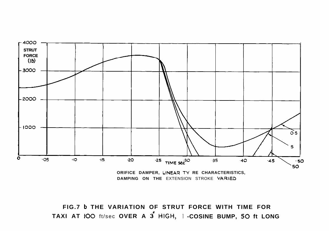
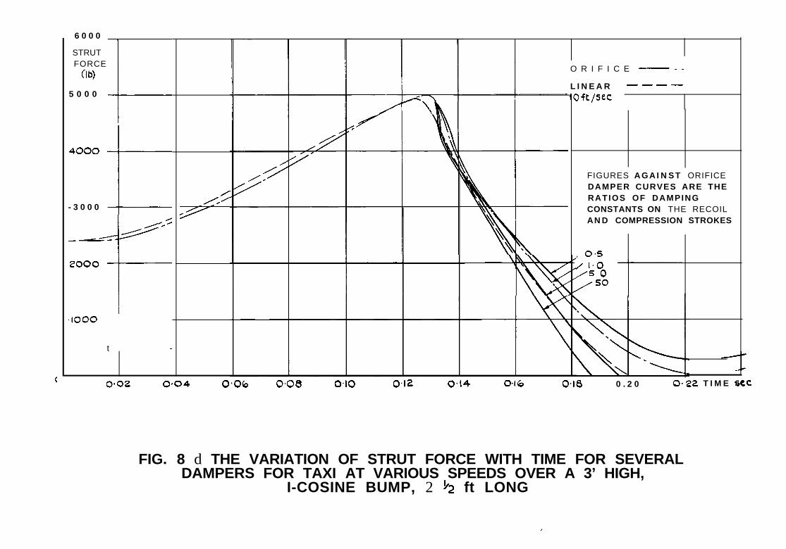
FiC.7a and 7'b show the effect of increasing the length of the highestbump to 50 ft at the same taxi speed. This produces a sharp reduction in thepeak strut load compared with the corresponding $2 ft bum2. The linear damperstill gives a slightly lower peak. Similarly the force amplitude is slightlyless for the linear damper than the orifice, which has low damping constant onth.-: recoil stroke. There is bounce for both the Enear damper and the oriricedampers having recoil damping constants higher than compression. The bouncetime is less for the linear damper. A comparison of results at 100 f't/secshows that the effect of inclaeasing bump length is to lower the mean forcelevel about which the oscillation occurs and to reduce slightly the amplitudeof the swing. Pigs.8a, b, c and d are concerned with the effect of changingspeed on the strut response when passing ever a bump of 3 in height and 2& ftlength. The maximum reaction is developed at an intermediate velocity for bothdampers, Figs.8a and b, this velocity is slightly higher for the orifice damper.There is little difference betwen the performance of the ti-io damgers except

5
In the equation defining pneumatic force the effective polytropicexponent depends on the rate of ccrnpression and the rate of heat transfer fraPnthe air to the surrounding environment. A value of 1.12 was eventlually chosenwhich was an average of the effective value for several landing gears'. Fcr .current designs in which the gas and oil tend to be separated by a diaphragmor alternatively the oil jet from the orifice is deflected frcm directimpingement on the gas, the value of 1.12 will be inappropriate. An exponentnearer to the adiabatic value is obtained and 1.3 maybe considered a typicalfigure: rn' and r in the equation defining the vertical force were chosen Onthe basis of drop tests to give the appropriate hysteresis loop to account forthe measured energy dissipation. The values appropriate to the 8.86 ft/sectouch-down speed are -
Region I: m' = 78.6r = I.34
Region 2: m' = 34.0r = 0.89
x IO3 lbfor 0 < Z2 6 0.352 ft
x IO3 lbfor 0.352 < Z2 c 0.364 ft
1,Region 3: mf = 157.1 x IO' lb
r = I.73 for 0.364 > z2 3 0.267 ft
Region 4: m' = 65.5 x IO3 lbr = I.34 for 0.267 > z2 > 0 ft
Subsequent calculations were based on linear tyre characteristics withno hysteresis, Fv = 18500 Z2 lb, as results of calculations of strut performance
gat 8.86 ft/sec on this basis by &Wlwitzky and Cook' shaved very reasonableagreement with measured characteristics and those of the more refinedcalculationsusing the nan-linear tyre characteristics.
Further landing cases were considered, in which the undercarriage toucheddown at velocities of 3, 7 ard II ft/sec respectively and in which for theorifice damper the damping constant on the return stroke was varied.
The taxi aspect of undercarriage operation was considered in two ways.
(i) By operating at varying speeds over (P-cosine) bumps of varyingheights and lengths, and
(ii) over an actual runway profile.

6
The latter part OJ? the investigation 5s to-da-kc limited jn scope. Theassumption Was made in all these calculations tiiat the c2.rcraft had landed asufficient length of time pri.or to the encounter with the bwrq for steadyconditions to have been established, i.e. there was ri0 vz;-tiCSl motion Of astrut when '-he bump was reached. A further assumption made in the calculationsxas that the tyre force developed as tile wheel passed wer an obstacle wasdirectly proportional to tne height of the bum2 (modified by the displacementcf the Tiheel itself) beneath the mheel axle. Unless cthewiso indicated,damping ctifficients in compression and recoil for tile orifice dampers willbe the same.
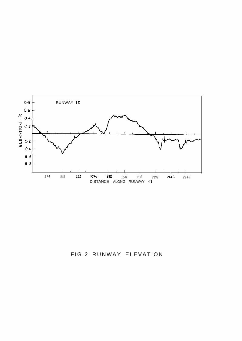
Data are available* of profile disp?acements measured at 2 Pt intervalson 3000 ft of Bunxay 12 at Langley Field and this -{Ias used as iqut data. Thevariation in profile bet;:een the tabulated values xas assumed to be linear.The aircraft sped over the profile l::as taken to be ccnstsnt at -ICX ft/sec.The profile is she-XI in FigY2.
Several methods for integrating the differential equations of ~3otionwere tried by Xilwitzky and COO~'~ Onz of time, the x-called quadraticp~OCdLl??e, 172s adopted here. 'I:15 variation of dls>lacemcnt over ko successiveintervals of time is assumed to be quadratic. This allo-us -Se velocity andacceleration at the mid-point of th c dotiole intervals to be exprosszd in termsof its displacement and those of the points irxxedin'iely prior and nfter inthe forx -
in = zvl 1 - zfl-la+2t;
nhere E the intagration interval was taken to bc 0.002 ss'c. Zis had beenfcxKnd to bc satisfactory in bhe originai papor and chack calculations in thiscase with tile interval reduced to O.GG$ set prokccd no detectable diffxcncein results.
3 3x !wLT s
3.1 Landing operation
The calculated strut force is plotted against stroke 170~ the ~-JO d~~~~pcrsin Big. 3. It, can be seen that the peak force development by the orifice damper

9
perhaps for the high taxi speeds, where the beneficial effect of the lineardamper is beginning to show. Figs& and d show the effect of inareaseddamping on the recoil stroke in the case of the orifice damper. Amplitude ofreaotion increases and the mean level reduces with increased recoil damping,the effect being most pronounoed at the lower taxi speeds. It is possibletherefore that current designs of undercarriage having recoil damping co.ns~an~s
that are higher than on crolpression.may be inadvertent* aggravating apotential fatigue problem.
Current designs of undercarriages have recoil damping oonstants whichare greater than those on the canpression &r&e. Typical values rangebetween 4 an3 2.5 times greater. YFe may therefore expect from the basis ofthe above results that a linear damper will exhibit better characteristics interms of peak force and force amplitude, than an orifice damper designed tohave the same stroke for a heavy landing. These effects are not very marked,however, and in view of the fact that the input for the calculations was nota particularly real one it was decided that a more rational basis for assessingthe relative merits of the two damper systems would be tomake calculationsin which the input was provided by an actual runway profile.
3.2.2 Runway profile
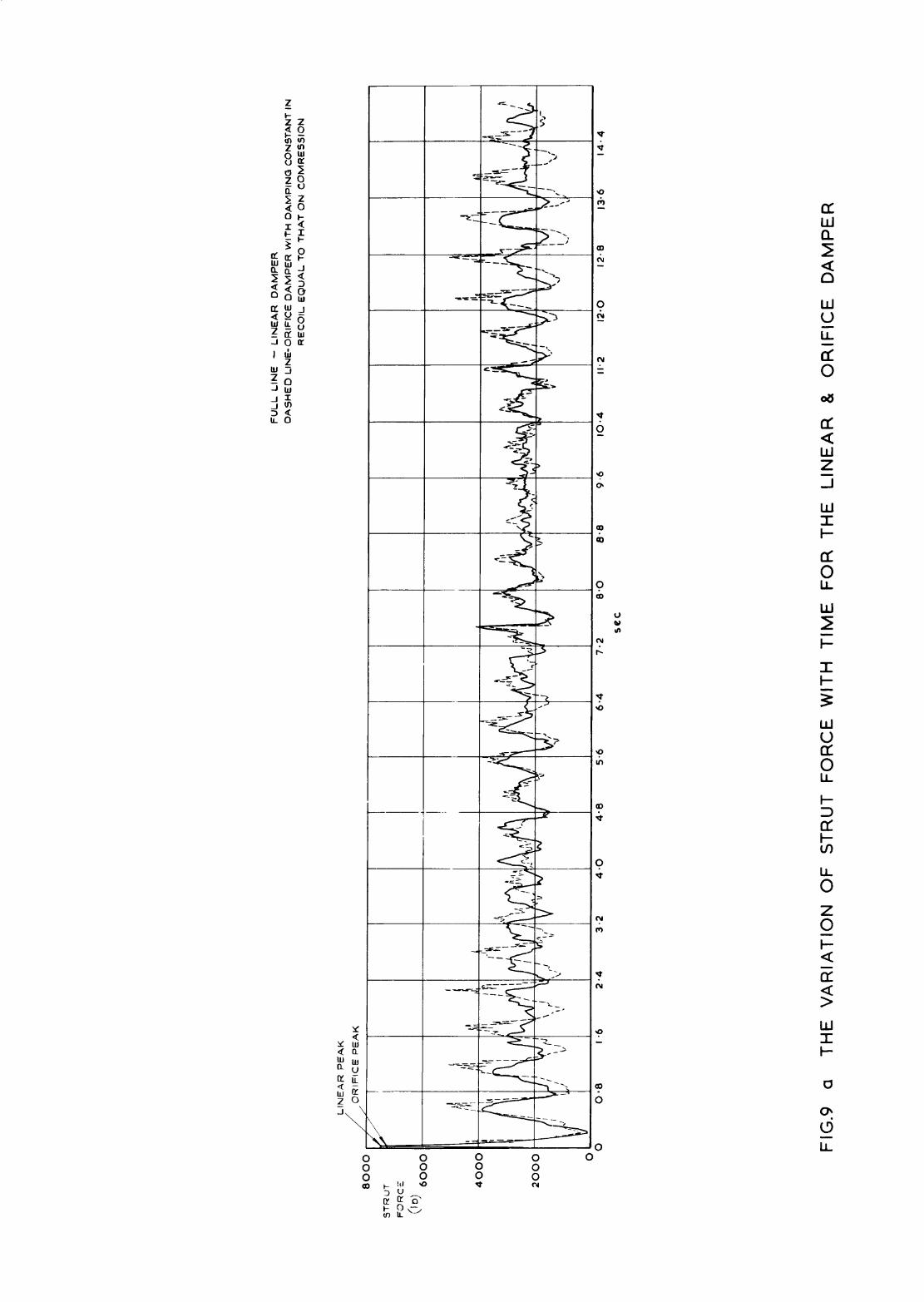
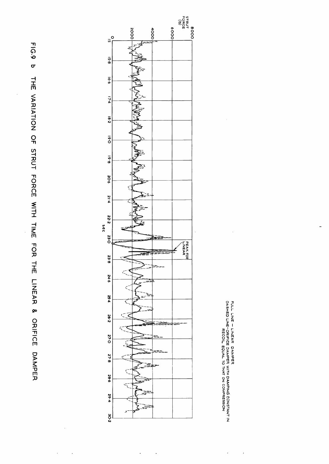
The results sre shown in Figs.Sa and b, where strut force developed asthe runway is traversed is plotted against time. The initial encounter withthe runway is equivalent to meeting a step 0.214 ft in height. The performanceof the linear damper on this surface is markedly superior to that of theorifice damper with which it is ccxnpared. Salient features of interestregarding the figure src listed below:-
(i) The damping of the oscillation resulting from the initial stepdisturbance and of subsequent high peaks provided by the linear damper is muchmrxe powerful than that of the orifice.
(ii) A dcminant low frequency response is revealed for both dampers.The aircraft oscillating as a rigid body in vertical translation on the tyrespring has a frequency approximately equal to that obtained with the lineartip= ; the frequency of oscillation for a linear damper case is about 2.0 to2.4 cps anI for the orifice damper 1.7 cps.
(iii) Over the smoother partions of the runway L+ to IO set and 15 to22 sea there is little to choose between the two dampers, but over theremainder of the runway length the linear damper scores heavily. Peak forces

IO
are consistently less usually by significant amounts and amplitudes of oscilla-tion are on average half those for the orifice damper.
( iv) Various other high frequencies arz apparent in the responsecurves. All of these would be important in regard to the structural dynamicreponsc. There is a particularly high frequency associated with this orificedamper, i.e. that having constant damping coof'ficient on coxpession and recoil.
(4 The particularly high response at around 23 seconds are associated.with a gortion of the runway that is notoriously rough.
4 DEXGN OF TH3 LJHIZAR DANEER
In "&ecrry damping that is linear with velocity of motion is obtainedeither by flow in a capillary or in an annulus. Both these methods wereconsidered in the design of a strut on which the comparative calculations werebased. It was eventually decided that the linear damper should be designedto have the same maximum stroke for a high velocity landing as the orificedamper with which it must Se compared. The design gave, as vJe have seen, a
reduction in peak strut force far this condition of the order of 13 ;?er cent.If the strut had been designed on the equivalence of peai: reaction in theheavy landing case, then a reduction in stroke would have been achieved of theorder ozf 5 per cent. On balance, the reduction in stress seemed preferable tothe reduction in stroke and consequent slight saving in weight.
Vsing the well established results, (I) and (2) below, frown fluid flowtheory, it can be shown that the damping face provided by annular flcnv isof the order of 40 times greater than that for capillary floiv through a singlepipe having the same cross sectional area and length. For capillary flow theretarding force is -
for annular flo;f the retarding force is -
F = 2 ( 2?
where P is the density of the hydraulic fluidV is the kinematic viscosityL is the length of +he channel
11
Dc is the capillary diameterd is the internal diameter of the annulus
is the thictiess of the annulusand k is the hydraulic mea.
In view of the potentially more powerful damping action provided by theannular flow it was decided to adopt this method.
Certain conditions must be satisfied to ensure that a true linear dampingaction is obtained. These are listed below -
li) The dsmping medium should be a perfect fluid - oils withviscosities less than 200 centistokes may be considered perlect in thisrespect. Any imperfections in the fluid will distort the response particularlyat law speeds.
Temperature effects will obviously be important for the annulus type ofdamper proposed. Changes in temperature would result in variations inviscosity and oonsequently, their damping force. It is suggested that suchvariations may be overcome by careful design, e.g. the use of materials havingdifferent coefficients of expansion for the piston and cylinder.
(ii) Clearance between piston and cylinder is small relative to thepiston diamzter.
(iii) The piston &muld be long enough to avoid sharp edge orificesffeots. If for sane reason this is not practicable it may still be possibleto achieve the appropriate damping action by careful attention to inlet andoutlet shapes to minimise losses.
(iv) Free area above the piston should be large so that oil velocityin this region approaches zero. Providing that the piston red is small varylittle oil is displaced as the piston moves into the cylinder and oil velocityabove and below the piston approaches zero. Ratios of piston to rod diametergreater than 3:l reduce the oil velocity past the rod to a suitably small value.
(4 The pi&on should be maintained concentric with the cylinder.
(vi) At high speeds and damping factors, forces maybe high enough todrop the pressure on the piston helm the vapour pressure of the fluid.Cavitation and aeration result and the damping farce is no longer proportionalto speed on the recoil stroke. We may note that orifice dampers arc possiblyworse in this respzot as peak loads may be greater under ultimate conditionsand damping forces larger.
12
All these points are covered by the design that is proposed, Fig.10.The maximum stroking velocity reached by the linear damper is 6 f-t/see in theheavy 11 ft/sec landing. The corresponding ?ieynold?s Number of the flow inthe annulus is 1103 for ambient temperature conditions, accordingly, theappropriate laminar flow is obtained for all operations considered. Theoriginal strut design, with which the performance of the linear damper iscompared in the calculations is shown in Fig.ll.
5 CONCLUSIONS
From the theoretical work that has been done so far we are led to theconclusion that there appears to be some justification for a fresh approach tothe design of undercarriage damping characteristics. A possibility investigatedherein involves the use of a damper, whose reaction characteristics areproportional to stroking velocity rather than the velocity square characteristicsof the conventional orifice damper. The results that are available to dateshd'i{ that reductions in strut force of tie order of 10 per cant for heavylandings are possible, using a linear damper. Such reductions are achieved
at the eqense of an increase in strut force at lower descent velocities. Itshould be noted however, that these forces are less than those due to thestatic load and less than the peak forces developed in normal taxying. Thereis an increase in rebound kinetic energy far the linear damper (having equaldamping coefficients on ccmpression and recoil) compared with that for theorifice with high recoil damping at al.1 vertical velocities of descent. Thelatter effect is most marked at low velocities where it might not beexpected to be vitally important. Apart from the ultimate case (11 ft/sec drop)there seems to be a rough equivalence measured in terms of rebound kineticenergy bctwecn the performance in recoil of the linear damper ati that of theorifice damper having three times the damping in recoil that it has in0zpression. The performance of the linear damper in the ultimate case issomewhat different in that recoil energy is higher than for all tie orificedampers considered. This result may be associated with a secondary effect dueto the lower mass, possibly a resonance. It is noticeable that the shape ofthe lipear curve, Fig.5, is a good deal different, (squarer) in this instancethan that of all otner strut force curves.
In regard to performance in the taxi phase of operation, the lineardamper appears to have markedly superior properties in that damping of largedisturbances is more effective, peak forces are smaller, ard the oscillating
12 13
force amplitudes are significantly smaller. The ccmpsrison may not be sofavourable when cases involving higher -chas of recoil damping arc considered,and this wcrk remains to be done. Other calculations that are in progress aimto assess the effect of various values of steady lift, to study the responsewith no step at the beginning of the runway and further when the taxi run isstarted at a different point on the runway.
In theory, it seems possible to construct a linear darrper but furtherwork should be done to prove th& this is a practiosble proposition, shouldthe ca7%xlations mentioned above prove to yield a favourablc result.
I sm grateful toI&. 3. 3. Sturgeon of Structures Dqartment, X.A.E., formany valuable suggestions and helpful discussions on problems that aroseduring the course of the work leading up to the canposition of this paper.

Case
Orifice damper,exp. tyreDR = D;
Linear damper,exp. tyre
Orifice damper,linear t.y-reDR = 0.51,
C
Dq = Dc.LDR = 5D,
DR = 5oDC
Linear damper,linear tyre
Orifice damper,linear t_vreDR = 0.9,
DP = DL C
Table ‘I
The velocities and kinetic energies at touch-down, recoil and reboundI-
Touch-down Kineticvelocity energyft/sec lb ft
Touch-down
t
8.86 3100 -1.8 -l.8 126 0.181
8.86 3100 -1.6 -1.6 110
3.0 356 1.6
3.0
3QO
390
3.0
7*G
7.6
356
356
356
356
1937
1937
-0.2
-0.2
-0.2
-0.2
-0.9
-I*5
-1.5
-0.2
-0.2
-0.2
-0.2
-0.9
-1.5
-1.5
1.6
1.6
1.6
32
88
0.186
0.193
0.193
0.193
0.133
0.199
0.192
88 ! O.lY2
4ft/sec
Recoil
22ft/sec
Kineticenergylb ft
tset
l-4
ft/sec
Rebound
-3.4
-3.3
-1.7
-I*4
-0.9
-0.7
-1.1
-2.5
%f t/set
Kineticenergylb ft
tset
-1.7 437 0.295
-1495 415 0.292
-0.1 108 0.493
-0.1 73.5 0.417
-0.3 31 0.333
-0.5 19 0.291
-0.5 46 0.239
-0.8 236 0.286

Touch-down
Case Touch-downvelocity I Kinetic
ft/seoenergylb ft
DR = WC
DR = 5oD,
Linear damper,lineartyre
7-o 1937
7-o -I 937
7-o 1937
Orifice damper,linear tyre 11.0 4790
DR = o.fjDc
'iI = Dc 11.0 4790
'>R = WC 11.0 4790
DR = 5oD l-t.0I
C 4730
Linear damper, 11.0 I+790linear tpe i
Table I (Con&)
RecoilI I
Rebound
2, 22 Kinetic t%
ft/sec ft/secenergylb ft set ft/sec
-1.5 -1.5 88 0.192 -2.2
-1.5 -1.5 88 0.192 -2.0
d-75 -4.75 121 0.198 -2.3
I I
-2.4 -2.4
Is5 0.165 -5*7
-2.4 -2.4 245 0.465 -5.5
-2.4 -2.4 ' 25 4 0.165 -5.3
-2.4 -2.4 Ii 245 0.465 -5.1I I
-0.85 ; -0.85 1I
29 1 0.153 j -5*7
82Kinetic t
ft/secenergylb ft set
-1.3
-1.7
-1.2
-2.8
-3.3
-4.1
-4.6
-3.8
11
183183 0.2560.256
156156 0.2420.242
201201 0.2540.254
12321232 0.2550.255
11501150 1 0.2510.251
10851085 o-243o-243
10301030 0.2370.237
!! 12601260 0.2570.257II
16
N o . Aut;hor iii *I-*lde, etc.
I B. Milwitzky Analysis of landirq gear behaviou-r.F'. E. Cook N.A.C.R. Report 1154, 1953
2 C.C. Tung The effect of runway uneveness on the dynamicJ. Penzien response of supersonic transports.2. Horonjeff K.A.S.R. CE-119, October, 196$

m, = UPPER MASS (THE AIRCRAFT )
mr = LOWER MASS (THE WHEEL UNIT)
z, = DISPLACEMENT OF UPPER MASS FROM
TOUCHDOWN POSITION
2, = DISPLACEMENT OF LOWER MASS FROM
TOUCHDOWN POSITION
kP = P N E U M A T I C S P R I N G S T I F F N E S S
kT - TYRE STIFFNESS
Ch = H Y D R A U L I C D A M P I N G C O N S T A N T
FIG.1 THE TWO DEGREE OF FREEDOM SYSTEM
USED IN THE CALCULATIONS
0.8 - RUNWAY (2
0.6 -
f 04-
0 6 -
0 8 -
I I I I L I I I I I I I I I I , I
274 548 822 10‘96 1370 1644 1918 2192 2466 2140DISTANCE ALONG RUNWAY -ft
F I G . 2 R U N W A Y E L E V A T I O N

7 0 0 0
6 0 0 0
5 0 0 0
4000
STRUTFORCEvb)3000
2000
f 0 0 0
ORIFICE DAMPER, F,,= 346-S (3 1sLINEAR DAMPER, Fh= 1095 iEXPONENTIAL TYRE CHARACTERlSTlCSDROP VELOCITY 8-86ft/SeC
0 0.2 0 3 o-4 05 0~6
STROKE (f t)
FIG.3 THE VARIATION OF STRUT FORCE WITHSTROKE FOR THE TWO DAMPERS

8000STRUT
FORCE
(lb)
7 0 0 0
6 0 0 0
FITt
/
I I
,7ftlsec
‘t)
ORIFICE DAMPER, LINEAR TYAE Cr,ARACTERISTICS.THREEVALUES OF TOUCHDOWN VELOClTY 3, I/AND II bt/SeC. DAMPINGCHARACTERISTICS ON THE ENTENSION STROKE VARIED-THREE VALUESCONSIDERED C-5, SAND SOTIMES THATONTHE COMPRESSION.DAMPING FORCE t=/, = 3 46* 5 1 ii 15 OR A MODIFICATION. FIGURES ATEN0 OF EACH CURVE GIVE APPROPRIATE DAMPING CHARACTERISTICS ONENTENSION STROKE. ON COMPRESSION STROKE 70 POINT WHERE
CURVES DIVERGE
G4 THE VARIATION OF STRUT FORCE WITH STROKE FOR-1REE ORIFICE DAMPERS AT THREE TOUCHDOWN SPEEDS

800CSTRUTFORCE
(lb)
7ooc
6OOC
SOQC
4ooc
3000
2ooc
1000
)-
P-
)-
P-
)-
I-
0
LINEAR DAMPER, LINEAR TYRE CHARACTERISTICS. THREELINEAR DAMPER, LINEAR TYRE CHARACTERISTICS. THREEVALUES OF TOUCHDOW~~ VELOCITY 3) 7 & I I f t petVALUES OF TOUCHDOWN VELOCITY 3,7 & I I f t (SK
OAMPING FORCE t=& - 1095 SOAMPING FORCE t=& - 1095 S
3 ft/sec3 ft/sec
0 0-I 0.3 o-4 O-5 STROKEOt)
FIG.5 THE VARIATION OF STRUT FORCE WITH STROKEFOR THE LINEAR DAMPER AT THREE TOUCHDOWN SPEEDS
6 0 0 0
5 0 0 0
STRUTFORCE
l b
4 o c o
3 0 0 0
2 0 0 0
1000
4 o o cS T R U TF O R C E
lb
AVERAGE &“lVA‘ENT “EI~TICA‘“E‘~&‘T’ 2Oft/SeC ORIFICE DAMPER
I I
--j(-- LINEAR DAMPER
4VERAGE EQUIVALENT VELOCITY loft FACE - - - ORIFICE OAMPER
I
- X -l
LINEAR DAMPER
AVERAGE EQUWALENT VELOCITY 2+t /XC ----- H ---- LINEAR DAMPER
I , ----- ORIFICE DAMPER
TAXI AT lOOk/SfZCOVER 3 %lGH, I -Co5BUMP 2.5 ft LONGTAX I AT looft /setOVER Ivi~lc~ 1x0sBUMP 2.5Ct LbNG.TAXI A T ioofthecOVER 0 SHIGHI-cosPUMP 2.5ft LONGI I I I I I,
0 O-01 0 0 2 0 ‘ 0 3 0.04 0.05 T I M E set
FE.6 THE EFFECT OF BUMP HEIGHT ON STRUT FORCE
- I
-ORIFICE DAMPER OVERA yHIGH
II
TAX I AT lOOft/Sd
--*LINEAR DAMPER I-COS BUMPsoft LONG
\
3 0 set
AVERAGE EQUIVALENT VERTICAL VELOCITY
f f t /set
*05 ,I0 .I5I
20 -25
FIG7a THE VARIATION OF STRUT FORCE WITH TIME FORTAXI 100 ft /set OVER A 3’HIGH, I - COSINE BUMP,
50 ft . LONG
STRUTSTRUTFORCEFORCE
ORIFICE DAMPER, L\NEAR TV RE CHARACTERISTICS,DAMPING ON THE EXTENSION STROKE VARIEO
FIG.7 b THE VARIATION OF STRUT FORCE WITH TIME FOR
TAXI AT 100 f t /sec OVER A 3’ HIGH? 1 -COSINE BUMP, 50 ft LONG

I I I0.06 0 . 0 8 0.10 TIME set
a
L I N E A R OAMPER 1I
OR I FICE OAMPER DASHED LINESDAMPING CONSTANT ON RECOILEQUAL TO TIIAT ON COMPRESSION
S T R O K E 1
LINEAR OAMPER- FULL LINEORIFICE DAMPER - OASHEO LINEDAMPING CONSTANT ON RECOIL -EQUAL10 THAT ON COMPRESSIONFOR ORIFICE OAMPER
0.04 0 . 0 6 b 0.08 o-10 0.12 T I M E 5
FIG.8 a L b THE VARIATION OF STRUT FORCE WITH TIME FORSEVERAL DAMPERS FOR TAXI AT VARIOVS SPEEDS
OVER A 3” HIGH, I - COSINE BUMP, 2r ft LONG

6 0 0 0
STRUTFORCE
lb
5000
4 0 0 0
3000
2ooo
IO00
- ook/sec-w-w 50 ft/secB ..- 2 5 ft/sec
0 o-02 0.04 0.06 0.08 o-10 TIME
ORIFICE DAMPERS WITH VARIABLE RECOIL OAMPlNGCHARACTERISTICS, LiNEAR TYRE CHARACTERlSTICS
set
FIG.8 c THE VARIATION OF STRUT FORCE WITH TIME FORSEVERAL DAMPERS FOR TAXI AT VARIOUS SPEEDS
OVER A 3’IHIGH, I-COSINE BUMP, 2i ft LONG
_ 6 0 0 0
STRUTFORCE
(lb)
5 0 0 0
,400o
- 3 0 0 0~/A--=-’---J,2000I-
~I000
t -
../
O R I F I C E ~ - -
L I N E A R - - - -)ft/sec
FIGURES AGAINST ORIFICEDAMPER CURVES ARE THERATIOS OF DAMPINGCONSTANTS ON THE RECOILAND COMPRESSION STROKES
, 0.5/ I*0/s 0/so l-
0.02 O-04 0.06 0.08 0.10 0.12 0.14 0.16 0.18 0 .2 0 O-22 T I M E SCC
FIG. 8 d THE VARIATION OF STRUT FORCE WITH TIME FOR SEVERALDAMPERS FOR TAXI AT VARIOUS SPEEDS OVER A 3’ HIGH,
I-COSINE BUMP, 2 b2 ft LONG
,

NOT TO SCALE
BEARINGS-PISTON ROO
-OUTER CYLINDER
/ S P A C E R
- P I S T O N
INNER CYLINOER
UPPER MA4S M, -2411 lbSTRUT CHARACTERISTICS
A, = 0*05761 Sqft
Ah = O-04708 Sqft
u, = oao3545 tuft
pa. = 6 2 6 4 lb/s+0
LOWER MASS M,=i31 lb
INNER CVLINOER INTERNAL DIA=Z936’PISTON OIAMETER = 2 84d’PISTON LENGTH = 0,’HYDRAULIC FLU10 EEL 6VISCOSITY OF FLUID=125 CENTISTOKES AT
AMBIENT TEMPERATURE.PISTON ROD DIAMETER=ANY CONVENIENT VALUE
LESS THAN 0.947”PISTON ROD LENGTH = !O”LENGTH OF OUTER CYLINDER 14/’ (APPF3pX)INNER DIAMETER Of OUfER CYLINDER 3 385 (APPRq
FIG.10 SKETCH OF ANNULUS TYPE SHOCK STRUT

BEARINGS
PI
u----WHEEL UNIT BELOW
NOT
1TO SCALE
‘ O R I F I C E P L A T E
UPPER MASS M,- 241 I lb LOWER MASS M,= 191 lbSTRUT CHARACTERISTICS
A, = O-05761 sp.ft PISTON OIAMETER = 2,936”
47 = 0 04708 Sqft ORlFlCE OIAMETER = O-32o*o = 0~03545CU St ORIFICE THROAT FORMEO BY PLATE O-&THICK
pa,= 6264 lb/s+ RADIUSEO AT 0 25” DOWN TO O-32”
OIAMETER ENTRANCELENGTH OF OUTER CVLINOER t4’(APPROX)INNER DIAMETER OF OUTERC Y L I N D E R 3+2SI’(APPROX)
FIG.11 SKETCH OF ORIFICE TYPE SHOCK STRUTCn England for Her Najesty’s Stationery Office by
the Royal Aircraft Establishlnent, Pamborough. Da.129528 K.U.
AJLC. C . P . No.951oaober 1966
625.13.012.563 :629.13.015.11 :533.6.013.423
A . R . C . C . P . No.~lootober 1%6
Hall, Ii. Hall. II.
scre TfBxmEmcAL SMxm c%au!ERMNo OIEO mE -1cAL STmSEs cmmN1Nc OIEODAHPINC CHARACTWlISTICS DhHPINo CHARACTERISTICS
The paper presents results of a study that hxi been nmde to investigat-the effect of damping characteristics on the perforrnrnce of an oleostrut. Conventional oleo struts employ orifice dampers in theinterests of providing high energy absorption for the design verticalvelocity of descent case. It is shorn that an equivalent strut i.e.one having the same maxifmxn stroks, utillsing a damning mchanismproviding a force proportionalto the stroking velocity, instead of thesquare of this velocity, will benefit by a 10 per cent reduction instress in the desiga case. Comparison of the pe~~formance of these
Tim paper pesents results of a study tint has been rmde to investigatethe effect of damning characteristics on the perfornbance of an 0100strut. Conventional oleo struts employ orifice dampers in thinterests of providing high energy absorption ror the design verticalvelocity or descent case. It is shcwn that an equivalent strut l.c.one having the same maxiram stroke, utilizing a danping mechanizpnIswAding a force proportional to the stroking velocity, instead of thesquare of this velocity, will benefit by a 10 per cent reduction instress in the design case. ComIwison 0r the perfontmnce of these
(Over)
629.13.012.563 :629.13.015.11 :533.6.013.423
@ver)
A&C. C.P. No.951October 1966
H a l l , I i .
629.13.012.%3 :629.13.015.11 :533.6.013.423
sora: TRlmErICALl smm3 CONCERNING OLWDAWING CHARACTERISTICS
The papr presents results of c study that has been made to investigatethe effect of damping characteristics on the performance of an olcostrut. Conventional oleo struts employ orifice dampers in theinterests of providing high energy &sorptlon for the Jesigll verticalvelocity of descent case. It is shown that an equfvalent strut i.e.one having the same maximum stroke, utilizing a damping mechanismwoviding a force proportional to th? stroking velocity, instead of the4uare of this velocity, will benefit by a 10 per cent reduction instress in the design case. Comparison of the performance of thes


C.P. No. 951
C.P. No. 951
S.O. CODE No. 23-9017-51