Embed Size (px)
Citation preview

Source of Acquisition NASA Marshall Space Flight Center
Astronomy & Astrophj~sics manuscript no. aa6287-06 ~Warch 5, 2007
Solar Confocal interferometers for Sub-Picometer-Resolution Spectral Filters
G. Allen G ~ ' , Chris ~ie t raszewski" Edward A. west ' , and Terence C. ~ i n e s *
' National Space Science and Technology Center, Marshall Space Flight Center, Huntsville, AL, USA 35812 e-mail: Allen. GaryGnasa. gov
* IC Optical Systems Ltd., Bcchcnham, Kcnt, United Kingdom BR34TW e-mail: [email protected]
Received xxxxx xx, 2006; Accepted xxxxx xx, xxx
ABSTRACT
Aims. The confocal Fabry-PCrot interferometer allows sub-picometer spectral resolution of Fraunhofer line profiles. Such high spectral resolution is needed to keep pace with the higher spatial resolution of the new set of large-aperture solar telescopes. The line-of-sight spatial resolution derived for line profile inversions would then track the improvements of the transverse spatial scale provided by the larger apertures. In particular, profile inversion allows improved velocity and magnetic field gradients to be determined independent of multiple line analysis using different energy levels and ions. The confocal interferometer's unique properties allow a simultaneous increase in both &!endue and spectral power. The higher throughput for the interferometer provides significant decrease in the aperture, which is important in spaceflight considerations. Methods. We have constructed and tested two confocal interferometers. A slow-response thermal-controlled interferometer provides a stable system for laboratory investigation, while a piezoelectric interferometer provides a rapid response for solar observations. Results. In this paper we provide design parameters, show construction details, and report on the laboratory test for these interfer- ometers. The field of view versus aperture for confocal interferometers is compared with other types of spectral imaging filters. We propose a multiple etalon system for observing with these units using existing planar interferometers as pre-filters. The radiometry for these tests established that high spectral resolution profiles can be obtained with imaging confocal interferometers. These sub- picometer spectral data of the photosphere in both the visible and near-infrared can provide important height variation information. However, at the diffraction-limited spatial resolution of the telescope, the spectral data is photon starved due to the decreased spectral passband.
Key words. Sun: atmosphere - Instrumentation: interferometers - Line: profiles - Sun: magnetic fields
1. introduction
Solar physicists are beginning, on a regular basis, to spatially resolve below 100 kilometer on the sun by employing optical 1-meter class, and lager, aperture telescopes (Schlichenmaier 2006, Bettonvil2004, Keil et al. 2004, Bernasconi, et al. 1999). It is conceivable to resolve to - 10 km in the next couple of decades with semi-monolithic or interferometric telescopes (Davis et al. 2005, Hammerschlag et al. 2004, Dam6 1994). These op- erational, under-construction, or conceived telescopes include Flare-Genesis (0.8 m), Themis (0.9 m), Swedish Solar Telescope (1.0 m), SunRise (1.0 m), McMath-Pierce (1.5 rn), Gregor (1.5 m), Dutch Open Telescope++ (1.5 m), New Big Bear Solar Telescope (1.6 m), Advance Technology Solar Telescope (4.0 rn), Magnetic Transition Region Probe (6.0 m) and Giant Solar Optical Telescope (1 1.0 m). This effort of larger apertures for improved spatial resolution has beeh conducted in unison with superior designs and techniques (e.g., improvements in (i) im- age stabilization by adaptive optics for ground-based observa- tortes, (ii) thcrmal designs to rcducc locally induccd seeing ef- fecls, (iii) polarization resolution by lowering instrumental cf- kcis, (iv) the size ol' the CCD arrays to increase the field of view, and (v) imaging processing LO allow improved data analy- sis). Radiative transfer theory has improved with advanced mag-
Sertd offpl.inr I-ecllrrsr.~ ~CJ : G. Allen Gary
netohydrodynamical numerical simulations at the sub-granular scales to resolve elemental flux tubes. However, visible-infrared, high-spectral-resolution narrow-band imaging filters at a spcc- tral resolution of AA/A 5 have not rcccivcd much attcn- tion. This spectral resolution is currently provided by the non- imaging Fourier Transform Spectrometer (FTS) on the National Solar Observatory (NSO)/McMatch-Pierce Telescope. Using the FTS and studying elemental flux tubes, Stenflo et al. (1984) point out that the spectral measurements can be independent of the unresolved spatial elements, and hence high spectral resolution is a key component to understanding the structure of the sun. Mathew et al. (2003) have used the 3 pm full width half maxi- mum (FWHM) spectral resolution Tenerife Infrared Polarimeter (TIP) and inverted the FeI 1.56pm Stokes profiles using the SPINOR code to obtain an estimate of the magnetic fields gradi- ent in an umbra1 region. In general, the line-of-sight spatial reso- lution derived from profile inversions should follow the improve- ments in the transverse (i.e., image plane) spatial resolution with larger apertures; however this will require sub-picometer spec- tral resolution. Tt is clear that the use of several lines with differ- ent magnetic, thermal, and Doppler sensitivities will help resolve the vertical information. However this process has its problems associated directly with the sensitivity variation which is used. i.e. different mass. different ions, different transitions, and dif- ferent Land6 factors. Through using a single transition and ex-
https://ntrs.nasa.gov/search.jsp?R=20070018817 2018-06-13T10:59:20+00:00Z

2 G. Allen Gary et al.: Solar Confocal Tnterferome~ :ers for Sub-Picometer-Resolution Spectral Filters
ploring the depth by its variation of opacity with position in the line (or response function) we avoid these sensitivity differences. Furthermore we will show that the trade-off between the signal- to-noise ratio and spectral resolution is acceptable. In this paper we present the spherical or confocal interferometer, an unnoticed technique in solar physics, which shows promise in combining high-spectral resolution and imaging, such that vertical gradi- ents in mass advective flows and marrnetic field madients can be '. '2
derived on a scale compatible with the horizontal gradients. Normal or planar Fabry-PCrot interferometers (FPP) have
a pair of mirrored parallel plates (etalons) and the light passes through the system when the gap between the plates is an integer number of the wavelength (Fabry and Ptrot 1902, Vaughan 1989). The FWHM spectral pass- band (AAFII~HM) is dependent on the separation between the plates. These FPPs are used as standard narrow pass- band imaging filters in solar physics in the US Air Forces Optical Solar Patrol Network (OSPAN, A/lFrvH~ -10 pm), University of Hawaii's Mees Solar Magnetograph (A,ZFII,HM -7 pm), Gottingen Astrophysical Institute's FPT (AAFIIrHM -6.6 pm), Arcetri Observatory's Interferometric BTdimensional Spectrometer (IBIS, AAFI{rHM -2.3 pm), Kiepenheuer Solar Physics Institute's Triple Etalon Solar Spectrometer (TESOS, AAFWHM -1.9 pm), and NSO/Sacromento Peak Observatory's dual ctalon systems (AAFWHM -1.7 pm). For narrower FWHM filters with larger gap distances, the confocal interferometer should be considered. A confocal (spherical) Fabry-Ptrot in- terferometer (FPS) differs from the parallel-plate interferome- ter in that the mirrored etalons are identical spherical surfaces where the center of radius is at the surface of the other mirror. (Confocal means having the same foci.). Because of the spheri- cal surfaces, the confocal interferometer can increase simultane- ously both the spectral resolution and throughput and should be the preferred choice of interferometers for sub-picometer spec- tral filters (Hercher 1968, Vaughan 1989).
The path of the light through the confocal interferometer is typically a figure-eight shape (Figure 1) with the exit beam re- entering the direction of the initial beam (to within paraxial ap- proximation) (Connes 1958, Hercher 1968, Clark 1972, Vaughan 1989). For the initial incident direction, the interference contri- butions to an exit ray come after 21k reflections, where k is a positive integer. The spherical mirrors and their associated thick- ness affect the final imaging and spectral resolution however we shall show this is not a significant effect. A main point of this paper is to describe the imaging quality of the confocal interfer- ometers and the possible improvements that they could provide for solar physics, since the conl'ocal interl'erometers have greater throughput and greater alignment tolerances than parallel plate interferometers under certain circumstances. An offset in con- focal mirror alignment results in only a change in the optical axis of the system, when the confocal distance, r, is corrected by nor- mal tuning. This results in a necessary alignment of the mirror centers to only the order of - 0.1 Dlr ; where as a planar Fabry- PCrot interferometer, the alignment tolerance for parallelism is on the order of - A / D , where A is the wavelength and D is the aperture.
One concern with increasing the spectral resolution is that this implies a deficit of photons as the spectral passband is re- duced, causing longer exposure times. This is obviously prob- lematic if the diffraction-limited spatial resolution is retained. For then the dependency of the size of the telescope is canceled sincc thc light collcctcd is a product of the tclcscopc arca and thc spatial arca sampled. If the apcrturc is varied it will bc found that thc product of thc tclcscope's apcrturc arca and thc area of
,.," sphericai\ j 'spherical mir ror 1 \,, I,// mirror 2
Fig. 1. The confocal optical configuration. In this configuration, the dis- tance, d, between the two spherical minors (bold arcs) is set equal to the confocal distance, r, the radius of the spherical mirrors. To ;he upper left of the confocal mirrors, a real object is located at S,. The transmit- ted light paths through the confocal mirrors and a lens are shown with the two resulting real images S; and S; formed by 22k or 22%2 mirror reflections. respectively. To show the symmetry of the optical path, the virtual object Sz is shown. In this figure, the distancep, from the optical axis of the entrant ray at minor 1 and its distance pl at mirror 2 are ap- proximately equal. The two spherical mirror focal points are F1 and F2. The two reflected beams (oblique dash lines) result when the resonance interferometric condition is not satisfied. (After Johnson 1968)
the diffraction-limited resolution element on the sun is constant. At the diffraction limit resolution, the exposure times are inde- pendent of the aperture size (Table 1, last column). Therefore, to collect a reasonable number photons for spectral analysis a re- duced spatial resolution is require, as we will demonstrate. We will now consider the exposure times for two wavelengths, one in the visible and one in the near infixed.
The exposure time is determined by the time it takes to fill each detector pixel well with electrons. This time is governed by the well capacity of the CCD and the numbers of electrons generated each second by the light incident on each pixel. This later parameter is itself determined by the quantum efficiency of the CCD and the number of photons incident each second on the pixel, n,,. To determine izp, we consider the total radiant en- ergy incident on a detector pixel per second, Pi. P, is equal to the solar radiant power per second per unit arca per unit wave- length interval at the wavelength o f interest, I(A), multiplied by thc wavelength passband, AAFWHM, thc area of thc telescope AT, and the effcctive arca of a pixel on the sun, f (AT), and corrected for transmission losses, t,: P, = I(A) AAFIVHM AT f(AT) ir. Thc fraction of the total area collected by the telescope that is im- aged on a detector pixel is equal to the ratio of solid angle of the projected pixel and the solid angle of the sun.
Observing at the telescope diffraction-limited resolution with the detector pixel size set by the Nyquist spatial frequency, the pixel size is half the diffraction-limited size. The projected solid angle of the pixel is then given by Rpr.rrl = T(E)'. The solid angle of the sun is Q,,,,, = 6.8 x 10-' sr. hence
f(AT) = %. Assuming A = ,lv = 630.35 nm, a telescope R,",, with an ctfcctivc arca of A,= 7854 cm', (i.e., D, = 1 m). givcs Qpilel = 1.2 x 10-I: sr, and $ ( A r ) = 1.7 x lo-'. In the con- tinuum, the incident solar flux is !(Av) = 1645 erg cm-: nnl-'

G. Alien Gary et al.: Solar Confocal Interferornc :ten for Sub-Picometer-Resolution Spectral Filters 3
s-' at the wavelength ,Iv. With optics providing a total optical transmittance of t, = 0.01 and a filter of A A F I Y H M = 1 pm, we have: P, = I(d) A A F w I I w A T f (Ar)t, = (1 645 erg cm-' nm-' s-')(0.001nm) (7845 cm') ( 1.7 x10-') (0.01) = 2.2 x10-' erg s-l . At a wavelength of Av=630.1 5 nm, each photon has an en- ergy of 3.1 5 x lo-'' ergs, so there is a flux of np = 6.9 x 10' photons per second on a pixel. With a 0.8 quantum-efficiency (QE) detector the number of electrons per sec is determined (11, = 5.6 x 10"). For a signal to noise of S/N = 1000, the num- ber of electrons needed to be collected is a million. Hence, the exposure times is 18 s. However for photometry we can use 2x2 pixel binning, i.e., a resolution element, and reduce the exposure time to 4.5 s to collect a million photons. In the near infrared at &=1564.85 nm where the diffraction limit spatial resolution is l y but the solar flux is lower, I ( iv) = 269 erg cm-' nm-I s- ; the photon flux is n, = 1.6 x lo5 photons per second per pixel and the exposure time is 2.9 s with an IR 0.5 QE detector. At both wavelengths it is assumed that the pixel well depth is WD = 1 x lo5 e-. Assuming Poisson counting noise is the dom- inate noise, the detector digitation then must be able to resolve &, e.g, 10 bit A D . Multiple reads of the CCD is necessary but we have assumed that the readout rate is a fraction of the ex- posure time, hence the readout is ignored. We also assumed that the dark current can be ignored when compared with the Poisson noise.
For one spectral position the exposure times are acceptable considering the solar dynamics time scales with respect to a di ffraction-limited resolution element on the sun. However to obtain a high-spectral-resolution line profile at 1 pm spectral res- olution and at the diffraction limit, the exposure time become problematic. Stepping at an interval of 0.5 pm over a spectral scan range of 30 pm, the photoelectrons for this line profile are obtained in 270 s at Av and 171 s for AIR. Of course, this is over the full field of view. To obtain the full Stokes profiles, the ad- dition polarimetry requirements increase the total time by a fac- tor of 6. Therefore, to obtain full Stokes profile scans in a time significantly shorter than the solar oscillation period, Lhe spatial resolution must be larger than the diffraction limit. For extended, horizontal stratified regions (e.g., penumbral Evershed flow re- gions) where resolving the vertical stratification is important, the employment of larger than diffraction-limited resolution would be acceptable and allow shorter exposure times.
A main emphasis for imaging interferometry is to provide high spatial resolution compatible with the spectral line informa- tion to be derived. The larger the gap between the etalon plates in either the parallel or spherical interferometers, the higher the spectral resolution becomes, i.e. the smaller the spectral pass- band. Since the l a g e ground-based and space-based solar tele- scopes, which are planned or being built, produce higher trans- verse spatial resolution on the scale of 10-200km (Table 1); it is desirable and necessary to also increase the spectral power to isolate the solar physics to a comparable spatial scale in the vertical direction. That is to dissect the line profile structure of the line formation region (e.g., photospheric lines have a height of formation FWHM -200-500km). In particular to determine the vertical (or line-of-sight) gradients of flows and fields. to the same scale as the transverse gradients of the flows and fields, and to interrupt the corresponding line asymmetries. The pres- sure scale height for the photosphere is -150km and the photon mean path is also on this scale.
Having high spectral resolution is important in determining the vertical gradicnts. Balasuhramaniam and Uitcnbrock (2001 ) invcstigatcd thc vclocity gradicnts ovcr thc hcight of formation of thc non-magnctic scnsitivc iron linc FcI 557.6 nni (Land6 fac-
tor of g=O). They showed with numerical modeling that a 0.5 pm passband is required to resolve the -100 m/s advective flows. A second example infers that a sub-picometer passband in the near infrared can determine the vertical magnetic gradient of the normal field. Sanchez Almeida (2006) showcd theoretically that the vertical magnetic gradient can be derived tiom high spectral rcsolution observations of a single Zeeman sensitive line. As an example of this, the difference between the spectral Stokes V profiles of a line formed within a magnetic field region with a decreasing gradient and of a line formed within a constant mag- netic field is plotted in Figure 2. Using the umbra M model of Maltby et al. (1986) with a magnetic field strength of B = 3000 G, velocities of v,,;, = 1 km/s and v,,,, = 0 km/s, an inclina- tion of 45 deg, and an azimuth of 45 deg, these magnetic field calculations were generated with vertical field gradients of 0, -3 and -6 G/km. Independent of the polarization strength, these dif- ferences can he resolved with sub-picometer spectral resolution. Observationally, Mathew et al. (2003) used a profile inversion pro.gram to infer a vertical magnetic gradient from the TIP obser- vations (AAFwHM = - 3 pm) and obtained a value of --4 G/km. With sub-picometer resolution, the magnetic gradient can be im- proved and compared with values from other Zeeman sensitive lines at higher heights.
Increasing the spatial resolution to well below lOOkm has brought about a bogus concern that visible photospheric struc- ture will be limited by photon diffusion to an optical mean-free- path, i.e. about one pressure scale height, due to smoothing by radiative transfer. If this were true, it would also effect the inver- sion of the line profile and hence set a limit on the useful spectral resolution. The argument was that the photon mean free path is -200km for unity optical depth at 500nm ( q = l ) (Allen 1973). Countering that argument, visible observations by Rouppe van der Voort et al. (2004, 2005) and Stein and Nordlund's (2006) hydrodynamic simulations have shown that much smaller struc- tures exist and a resolution of less than 100 km is required for the photosphere. Bruls and von der Liihe (2001), in an analysis of radiative transfer effects on the visibility of small-scale struc- tures, performed 2D non-LTE radiative transfer computations for thin flux sheets with widths ranging from 10 to 160 km in the solar photosphere. They demonstrated that such small struc- tures could be observed as small scale variations of intensity and polarization. With the conclusion that the size limit where the photospheric structure cannot be observed (due to smoothing ra- diative transfer effects) must lie well below 10 km. Synthesis of line profiles from dynamical flux tube simulations suggests that visible structure in Stokes V will exist down to size scales of 5 km (Stein and Nordlund 2006). Hence scales much smaller than 100km should be resolvable with imaging and spectral profile inversions.
In the next section we will compare the confocal interferom- eter with other spectral filters in terms of field of view and aper- ture size. Then we will provide initial design parameters, explain the construction details for two designs, and report on the labora- tory test of these units. In the conclusion, we will propose a mul- tiple etalon system for future testing the piezoelectric-controlled unit to obtain sub-picometer spectral profiles of photospheric in both the visible and ncar-infrared. Thcsc observations will cm- ploy existing planar Fahry-Pcr6t intcrfcromctcrs as prcfiltcrs to the confocal systcm.

4 G. Allen G q et al.: Solar Confocal Interferometers for Sub-Picometer-Resolution Spectral Filters
Table 1. The diffraction limit resolution for larse solar telescopes usins values in the text ( A = 630.2 nm/ 1564.8 nm)
Telescope aperture Angular Resolution Spatial Resolution Number of DifTraction Full-Well-Depth Exposure Times at Die/ &ijj AX Elements per arcsec Diffraction Limit with 1 pm FWHM (m) (arcsec) (b) 6) 1 0.16 / 0.39 115/285 3916 0.16/0.02 2 0.08 / 0.20 57 / 142 159 / 26 0.16 / 0.02 4 0.04 / 0.10 29 / 71 639 / 103 0.16 / 0.02 6 0.03 / 0.06 19/48 1431 / 232 0.16 / 0.02
Wavelength [nm] Fig. 2. For the infrared iron Zeeman line at ,i1~=1564.85 nm, two dif- ferential Stokes V-profiles are shown. A differential profile is the dif- ference between two Stokes profiles with one profile originating within the magnetic field with a vertical gradient and the other with a constarit (zero gradient) magnetic field. The two different gradients plotted are -6 G kn-' (thick line) and -3G km-I (thin line). A sub-picometer res- olution will discriminate between these models, with sufficient photons
signed for one wavelength while confocal interferometers can cover a wide range of wavelengths dependent on the reflectiv- ity function of the etalon coatings. The relative wavelength shift, 6/1/A, as a function of the off-axis oblique chief-ray incident an- gle 6' is given by 6,1/1//1- lKQ2/21, where constant K is 1, l/no2, be-no)/2n,no2, (p~/nz-pl/n,) 1 ( P ~ ~ ? - P I ~ I ) , and Q2/2 respectively, for a air-gap Fahry-PCrot filter, a solid Fabry-PCrot filter, a wide field Lyot filter, a solid polarizing Michelson interferometer, and the confocal interferometer, where (n,, n,, nl, & nz) and (pl& pz) are particular refractive indices and thicknesses (Gary et al. 2003, Hercher 1968). From these wavelength relationships, the confocal interferometer is nearly equivalent to the Michelson fil- ters, and these have an advantage over an air-gap Fabry-PCrot interferometer because a larger effective field of view can be ob- tained, or, equivalently, a smaller aperture can be used with a given field of view. The decrease in aperture for an air-gap in- terferometer is a factor of -2 for a solid-gap (LiNb03) etalon, a factor of -10 for a wide field, birefringent, Lyot filter with split-calcite elements, and a factor of -100 for a confocal and a polarizing Michelson interferometer. However, for the ability to make multi-wavelength observations at sub-picometer spectral resolution, the advantage goes to a confocal interferometer.
and polarimetry. For the visible line, d=AI~, the splitting is a factor of ( R ~ ~ R ~ ~ ) ~ - 116 weaker, while the ratio of the splitting to the Doppler 2.1. On-Axis Modeling the Confocal Interferometer
width is a factor of - 113. further requiring the sub-picometer spectral The characterization of a parallel plate Fabry-PCrot interferom- resolution. The AIR line width is 10 pm (Solanki, Riiedi, and Livingston 1992) eter (FPP) for a telecentric beam configuration gives an effec-
tive FWfIM dependent on the maximum angle of incident (Q), while for a collimated beam configuration there is a variation
2. Confocal Bnters'erorneter Comparison with Other Filters
We will now compare the confocal interferometer with other imaging filter systems. For a 4-meter aperture telescope and for a given set of field of views (FOVs), Figure 3 compares the op- tical aperture requirement for the confocal interferometer with an air-gap and solid planar Fabry-PCrot interferometer (FPI), a Lyot filter, and a Michelson interferometer. It shows that for a particular on-axis spectral resolution (e.g., 0.5 pm, dash hori- zontal line in upper panel) that the off-axis oblique chief ray at the incident angle produces an identical wavelength shift at the edge of the FOV of the same size as the on-axis resolution. For the particular filters this spectral shift is dependent on the refrac- tive index of the gap or the particular type of interferometers. This typically sets the spectral resolution requirement for a col- limated or telecentric optical system (Gary et al. 2003) and is due to the fact that the oblique chief ray angle in the interferom- eter sets the limits to the FOV for a given spectral resolution, via the Lagrange invariant or the ratio of the telescope aperture to the interferometer aperture. The confocal interferometer is simi- lar to thc Michclson intcrfcromctcrs in that it allows for a small apcrturc intcrfcromctcr, compared to thc 100 mm plus ctalons for thc air gap ctalon. Thc solid Michelson intcrfcromctcr is dc-
- of line center across the FOV. The single etalon equations for the central wavelength A,, free spectral range FSR, total finesse F, reflectance finesse FR, integer order number m, and passband (ARFlrrHn4) are given by the we!l-known relations: (i) ,lo= 2 n d cos(B)/m, (ii) FSR= ,lo2 1 2 n d cos(B), (iii) FR = x R ' ~ ~ / ( ~ - R ) = - rr/ In R, and (iv) AAFWHM = FSR/F, where d is the etalon gap distance for parallel plates, n is the refractive index of the gap, R is the coating reflectance, and assuming no optical defects, i.e., F=FR (Vaughan 1989). For small angles the wavelength shift is 6A=A,,Q2/2 (Figure 3). These inter-relationships determine the specific requirements for the parallel-plate filter. In particular for the planar Fabry-PCrot the ratio of the spectral resolution (NZL = A / A/lFUrHM) to the Ctendue ( UFpp = l m 2 A / 4dFR ) is given by N,,/ UFpp = 4x(r(a2/ 2 D 2 ) ( 2 ~ ~ / nil)', where D is the aperture size (Herscher 1968, Vaughan 1989). Increasing the gap distance increases the spectral power Nn - d but decreases the Ctcndue UFpp - 1/ d.
Setting the distance between mirror centers, d, to the ex- act confocal separation, r, the corresponding on-axis, paraxial formulae for the co~zfoccrl (spherical) Fabry-PCrot interferome- ter (FPS) are: (i) ,I,,= 4 n r/m. (ii) FSR= .I,,' / 4 n r, (iii) FR= rR/(l -R'), and (iv) A,tFIirIIM = FSRF (Vaughan 1989). The use- able aperture or pupil spot radius is given by /I, = (r' 2/FR)li4, assuming the FWHM at this edge is within 2-'1' of the central

G. Allen Gary et al.: Solar Confocal Tnterferometf ers for Sub-Picometer-Resolution Spectral Filters 5
I 1 7
Incident Angle in Air at Filter (arcmin)
Incident Angle in Air at Filter (arcmin)
Fig.3. The upper panel plots the wavelength shift (61) as a function of the incident angle of the oblique chief ray for a collimated beam config- uration for the set of filters discussed in the text. For the shift of 0.5 pm the intercepts the various filter curves are plotted. Extrapolating these five-filter intercepts into the lower panel, the corresponding filter sizes for a 4-meter telescope is given for three field of views (FOVs). In the upper panel, the confocal interferometer curve is shown as a dashed line where the aperture is smaller than -5 mm, a manufacturable constraint. (After Gary et al. 2003)
FWHM (Vaughan 1989). If R is the beam solid angle, A is the usable aperture area, and the refractive index is set to unity, n = 1, the confocal Ctendue is given by UFps = A R = [K pr2][n p,' /r2] = 2n2 r A / FR and the spectral power N,I =A/A/ lFfv~~ = 4 r FR / A; hence the ratio of the resolving power to Ctendue for the confocal Fabry-PCrot interferometer is given by N,l/UFPS - 0.7 (2 FR/ n R )2. Hence both the resolving power A/A,lFIVHM - r and the Ctendue UFPs - r increases with the confocal sep- aration distance. For a fixed finesse, the confocal interferom- eter can increase simultaneously, both, the spectral power and throughput. For the same FSR and for r- d/2, the FPS becomes a better choice than the FPP when r - 40 mm because of the defect finesse (Hercher 1968). For the FPP parameters, d>2'I2D, the Ctendue relation UFps>UFPP states that the confocal inter- ferometer has greater light collecting property (Vaughan 1989, p. 194). For large-aperture solar telescopes, the critical result is that a smaller aperture can be used for the same number of pho- tons passing through.
We have designed and built two sub-picometer confocal in- terferometer both performing in the visible and near infrared. Each FPS was designed with a A,lr;.wII,Lj=0.13 pm (FSR=2
Fig.4. The relation between the FWHM and the FSR as a function of confocal separation (r) and reflectance (R) is plotted. The confocal sepa- ration distances r in millimeters associated with Lv or AIR are seen at the top or bottom, respectively, of the set of constant reflectance curves. For the particular reflectances, the separations are shown as small boxes. For clarity, the confocal separation distances of the two wavelengths are, in general, on separate reflectance curves. The solid filled squares are for r=50 mm, and the two largest fill squares (for l i r at the left and AIR at the right) are associated with the confocal design of R=0.92 and r=50 mm.
pm) at Av=630.2 nm and AAr;.kvHnf =0.8 pm (FSR=12 pm) at AIR=1564.85 nm. This allows the solar FeI Zeeman sensitive lines at Av and AIR to be scanned and allows a frequency stabi- lized HeNe laser line (AHeNe=632.8 nm) to be employed for lab- oratory test. The relationship between FSR, FWHM, reflectance, and confocal separation is shown in Figure 4 for the visible and near infrared lines. Although the plot of reflectance versus FSR and FWHM is independent of the wavelength, we have sepa- rated the line plots into two reflectance groups in order to show their correlation with the confocal separation distances for /Iv and ,IIR For the two wavelengths, the largest two squares plot the corresponding design values for R=0.92 for the same sep- aration distance, r=50 mm. The set of box symbols at the or- dinate FSR=1 pm refer to a separation of r=100 mm for A". The reflectance finesse is FR = xR/(l-R2) = 18.8 and the resolv- ing power is N,I = ARFUrHM//Z = 4FRr/R = 5x10⁶ for ,lv and 2xlO"or AIR. This implies a confocal separation distance of r =50 mm for sub-picometer spectral resolution, and for ease of manufacturing the first units for testing have an aperture of 25 mm. Because of the root-mean-square (RMS) irregularities and roughness of the spherical surfaces, the total finesse is a combination of the reflectance finesse FR and the defect finesse Fd,,,,,. For a RMS inegularity of 6RIPMS=/I/r), the defect finesse is FdrJrcr = 712 (Hercher 1968). Hence to have FdeIccI to match the FR(R=0.92) then q=38 and 6RMS=A/38, which is a reasonable smoothness for the spherical etalons. For these values the to- tal finesse F is then ~ = ( l / ( i / F ~ ' + I~, , , , , ' ) ) '~ '=~- ' /~FR.= 13.3. This is an effective ref ectivity of 0.88. The FWHM design val- ues become bflFnrH,o=0.15 pm and 0.90 pm. Inversely, if we had selected the total finesse to be 18.8, then the reflectance and de- tect finesse must he 26.5 which give R=0.943. Hence the final design reflectance value was set to be R=0.95 k0.02 with sur- face figure to he better than i\/4O.

6 G. Allen Gary et al.: Solar Confocal Interferometers for Sub-Picometer-Resolution Spectral Filters
2.2. Off-Axis Modeling the Confocal lnterferometer and Imaging Theory
An optical configuration for the confocal interferometer is shown in Figure 1 within the paraxial approximation. The rays starting from Sl after making quadruple (or 22k) reflections are reentrant with the original direction. After making two reflec- tions or 2"", another set of rays emerge and form an additional image (S;). For each of the two beams, the FPS intensity is 50% that of a FPP, however, in principle, the second beam could be recombined or used. This second image appears to be coming from the virtual source at S2. There are two beams that emerge back toward the source side (dashed arrows in Figure 1). Clark (1972) gives the imaging relationships for an imaging confocal optical interferometer with the etalon plates with a radius of cur- vature given by r and a separation of d = r+e, where e is a small displacement. For e=O, the separation is the exact confocal dis- tance. The phase difference for the rays is given by
where pi and p l are the distances of the ray from the optical axis at the first and second spherical etalon surface, 60,-,,is = 8r(r+e)/,l is the on-axis phase difference; and, for p = pl = pl, the off-axis phase difference is given by:
where a =2p/r (Vaughan 1989, eqns. 5.6 and 5.7). Using Fermat's principal, Clark (1972) determines the best focus, for a specific p, using the central diffraction angle a, for which acu=O. This also sets the largest range of a for which the spectral information is passed and the associated spatial resolution. For input intensity Io, the output diffraction intensity for the S; is given by
and a, = (-8e/r)'/? A plus and minus sign denotes if the wave- length is longer or shorter than the central peak. On the two sides of the intensity peak at HWHM (half width at half maximum), the phase difference is 6,= (2~/,1)(- 4e2/r + AJF) + 6,,-,,is, hence the cutoff angles become,
which gives the variation of acceptable angles for which the passband is within FWHM. Hence if a - = O then (~+=(64A/rF)'/~ - 2.8 ( A / ~ F ~ " H ~ / / ~ ) " ~ = 5.15 deg. This is consistent with the an- gle 2pJr -2(,l/r~~)'/ ' - 3.6 deg, derived form Hercher's (1968, eqn. 17) spot radius. Therefore the FOV is approximately 4 deg.
3. Construction of a Confocal Interferometer
For testing the image quality of the confocal interferometers, we have constructed two confocal interferometer using IC Optical Systems spherical mirrors of r=rl=50.065 mm internal confocal radius and external radius of r2=60.30 mm. These 25 mm diam- eter fused silica plates (n= 1.459) have a 15 mm clear aperture and a plate thickness of 10.235 mm. The measured mirror coat- ing transmittances is 5.13% at 630.98 nm and 4.97% at 1564.2 nm. The exterior surfaces, with anti-reflecting coatings for both
Sensor ', Holder,' I I
I
Piezoelectric-Controlled Confocal interferometer
~herrnall~-'Controlkd Confocal Interferometer
Fig. 5. Schematic of both of the confocal Fabry-Ptrot interferometers. Two sets of lines (dotted) shown have radii of confocal radii R, =50.065 and R2=60.30 with their radii centered at the center of interior mirror surfaces M1 and M2.
a relative low-power, large focal length of f - -623 mm (while an optical Zemax code gives f- -925 mm).
In order to calibrate the etalon we need to be able to scan j-free spectral ranges, i.e., the confocal displacement should be id , = jj/4n, a few-microns. The spectral resolution should be - 111 0"' of the A/lFWIIIM, or about (,t/4n)/(lO F). To infinitesimally displace the mirrors by this amount, the two confocal interferom- eters were designed to have good mechanical and environmental stability (Figure 5). The piczoclectric-controlled interferometer follows ihc design by Budker el al. (1999) (cf., Vaughan 1989. sec 5.5.1). The thermally-controlled FPS design was engineered to allow initial precise displacement near the conPocal separa- tion.
- -
wavelengths (R<0.25%), were made concentric with a radius of 3, ,, Piezoelectic-Tunable FPS curvature of 60.25 mm. Bv em~lovinrr concave-convex etalon < - plates and the plate thickness. the optical power of each etalon The piezoelectric controller utilizes a thin-wall hallow cylin- plate is minimized for imaging quality and spectral resolution. der of lead zirconate titanate (PhZro,szTio,4s03, PZT) made of The thick lens formula f-'=(n-l)(l/rl-l/r? + (n-l)/n rl rz) gives Channel Industries C-5700 and milled hy Boston Piezo Optics

G. Allen Gary et al.: Solar Confocal Tnterferomt :ten for Sub-Picometer-Resolution Spectral Filters 7
r =50mm 1. = 630.2 nrn
-0.4 -0.2 0.0 0.2 0.4 0.6 0.8 1.0
Departure from the Confocal Position (mm)
Fig.6. Near confocal Fabry-P6rot fringe patterns. The curves give the radii of the circular interference pattern Tor collimated light in the parax- ial approximation.
Thermally Controlled
Piezoelectric Controlled
Fig.7. The ~wo consltucted confocal inlerferometers wilh suh- picometer spectral resolution. For each, the confocal distance is 50 mm and the aperture is 25 mm.
to a length of 10 mm, outside diameter 25 mm, and wall thick- ness of 1 mm, and nickel plated (Figure 7, lower panel). For a voltage V, the linear displacement along the cylindrical axis is given by Ad =d3, L V/ t, where dsl= -0.25 nm/volt is the piezo- electric constant, L is the length of the cylinder, and t is the wall thickness of the cylinder; then Ad = 2.5 nm . V or Ad = 4.1~10-' ,t V at /Iv=630.2nm. A voltage of 60 volts allows tuning through one free spectral range for the visible line. For a finesse of F= 13, then the displacement resolution of the tube should be 1.2 nm or -,1/500 with a voltage resolution of -f volt. The coefficient of thermal expansion led to a displacement of - 40 nm/C, hence the temperature needs to be stable or known to within -0.1 C. The calibration between voltage and displacement is required to correct for hysteresis and nonlinearity (Figure 8).
The construction schematic is shown in Figure 5. The rear fixed mirror (M2) is in a grove attached with cyanoacrilate ad-
0 20 40 60 80 100
Piezoeletric Voltage (Volts)
Fig. 8. Piezoelectric-controlled FPS scans of the HeNe laser line. The data is partially corrected for thermal drift. The solid lines are scans with the PZT voltage increasing and the dotted lines are with voltage decreasing. The separation of profiles set shows the hysteresis effect which can be corrected.
hesive. The front mirror (MI) is attached to the piezoelectric cylinder (PZT) with epoxy. Between the Invar steel mounting tube and the PZT ceramics cylinder, a thin plastic-shim angu- lar ring is placed to insure that the nickel electrodes of the PZT will not be shorted by touching the steel tube. The shim is at- tached to the Invar by cyanoacrilate adhesive. The PZT cylinder is attached to the shim and to the Invar via epoxy. There is a section of the shim material (1/8"' of the ring) that is missing and hence the epoxy over this section is directly attached to the Invar. The wires to the PZT cylinder were attached to the nickel coated walls using Sn-62 solder. The steel parts are milled Free- Cut Invar 36 Alloy which is a low thermal expansion alloy, and allow a threaded-screw displacement for setting the initial sepa- ration of the mirrors.
3.2. Thermally-Tunable FPS
The thermally-controlled design uses a 50 mm-long glass cylin- der between the confocal interferometer mirrors (Figure 7, up- per panel). Initially an all Zerodur glass cylinder was considered with a thermal coefficient of expansion of CTE=0.05 ppm/C. Using a thermal system that controls the temperature to AT=O. 1 C, implies controlling the spacing by steps of Ae = e C T ~ AT = 50 mm . 0 . 0 5 ~ 1 0 - ~ .0.1 = 0.0025 nm. However, for a system working in the IR at ,11~ (or in the visible at /Iv) this change rep- resents a change in the filter wavelength of 62 =4 &elm; note that 6e refers to a small displacement associated with a wavelength change 6,l and Ae is a small displacement associated with a tem- perature change AT. The offset order l i z is given by h= 4 e/J, hence 61 =(6e/e) A= 5X 10-'/I and for ,i=,lrR (or /l=Rv), then 6/lIR =7.8 xlO-' pm (or 6Ali=3.1 x10-' pm) which is quite small and implies prohibitively large changes in temperature. The FWHM is given by FSR, A2/(4e), divided by the finesse F. Hence, with the refractive index n=l, the intensity profile FWHM is AAFIvHM = ~ ' / ( 4 e F). For R-0.90, the confocal finesse is F-15; AIFlr~Hrr -0.8 pm for ,IIR; and A,l,qf~,l{ -0.13 pm for ,Iv. Again, 6A needs to be some fraction of the FWHbT in order to measure the line profile, i.e., 6/t/A,.LI;I~~II,CI <I but 6,1/ A,lFrtilr.w - 7.810.8 = 9.7 for AIR (or 6,i/A/lF1vllM - ~.1/0.13-24for ,it;). Hence, with Zerodur, the spectral line profile is unresolved by thermal tuning

8 G. Allen Gary et a].: Solar Confocal Interferometers for Sub-Picometer-Resolution Spectral Filters
Table 2. Initial thermal design requirements with R=0.9
,IV = 630.2 nm , IIR = 1564.85 nm FWHM 0.10 pm 0.40 pm FSR 2 pm 15 pm Step Size 0.02 pm 0.08 pm (at 5ptsFWHM) Number of points to 100 188 cover the full FSR Change in temperature 10C 19C reauired to cover FSR
for reasonable total changes in temperature. Therefore, the ther- mal control design was refined.
The refinement was produced by employing a dual-glass cylinder (BK7 and Zerodur) separating the spherical mirrors, where the thermal expansion of the glass cylinder controls the inter-etalon spacing. Assuming a set of characteristics for the FWHM and FSR at ,Iv and AIR and assuming that at least 5 points are needed across the FWHM to define the profile suf- ficiently, then Table 2 was generated assuming that the thermal control resolution is 0.1 C. Using (6e/e)= (CTE AT) =(6,1/,1) and with the assumption that set 6Av = 0.02 pm, i.e. the step size, and &AIR = 0.08 pm for a change of AT=0.1 C, then (6e/e)v= (0.02~10-'1630.2) = 3.17x10-', (0.08~10-'/1564.85) = 5 . 1 ~ 1 0 - ~ for AT=0.1 C. Therefore, with a change of AT=1.0 C, we have the thermal coefficient of expansion requirements for the respective wavelengths: CTEV = (6ele)" = 3.17x10-~ and CTEIR = (6e/e)1~ = 5 . 1 ~ 1 0 - ~ . Using a segment of length of L I of Zerodur (denoted by Z) with its TCE C T E Z = ~ X ~ O - ' and a segment of length L2 of BK7 with cTEBK7=7.1~10-~ then we can obtained the correct overall CTE by solving: LI CTEZ + Lz CTEBR7 = (Ll+L2) CrEV for 630.2 nm. Hence if the over- all length is L=Ll+L2 then LI(CTEZ- CTEV)=(L-LI)( CrEV - CTEBK~ ) or Ll= L (CTEV - CTEBK~ )/( CTEV - CTEBK~). For Ll/L = (3.17x10⁻⁷-7.1x10⁻⁶)/( 5.0x10-~+ 7 . 1 ~ 1 0 - ~ ) = 0.962 and for L=50 mm, then Li=48.1 mm for Zerodur and L2=1.89 mm for BK7. Therefore by introducing a 1.89 mm segment of BK7, the combination provides the correct over all CTE need for the vis- ible. The values to meet the correct CTE for the TR needs to be L1=46.74 mm andL2=3.26 mm which was the final design spec- ifications, since they also satisfy the visible requirement. The electric requirement for 20 C temperature range and controlling the individual tripod of legs to 0.1 C is provided by a ternpera- turc transducer (type AD590) with a heatcr strip. The measured time constant for the constructed intcrfcrometcr was 360 s. The resulting temporal sensitivity is too long for solar observations; however the dual-glass cylinder has no associated hysteresis.
4. Alignment
The parallel plates of a FPP must be exactly parallel, i.e., to within R/D radians. Conversely, because of the spheri- cal shape of the FPS, the alignment of the centers of the mirrors needs to be only roughly aligned, to within about O.lD/r-lo-* radians. This allows the axial alignment to be glued in place with no further improvement in tilt. However, for the axial separation of the confocal mirrors, the precision is more critical than the axial alignment and is given by 16 I = (2 r /32F~)'/', hence, for r = 50 mm, = 1.564pm, F= 15, I E I = 13pm - 8,1 (Vaughan 1989, p. 195). However, setting the initial separation is straight for- ward (Hercher l968), and is hased on the fringe movement ahout the confocal separation. The fringe pattern rad~us for fringe or- ders )?I=[-10,l 01 is plotted versus the departure from the con-
Fig. 9. An image of part of an Air Force Resolution Chart imaged at ,1=630.2 nm through the FPS. Both esit images (S; and S;) of the FPS are seen.
focal position in Figure 6. The thick solid line is for liz=O. The dotted line is the maximum radial dispersion curve (dp/d,l). For scale, a rectangle is defined by the spot radius of p, and depar- ture of w=i100A. The wavelength is for the photospheric visible Zeeman sensitive line (Av=630.2 nm). Spot radius p, is defined when the actual FWHM is A2,,,,,r=1.42 A/lFRrHM. If the con- focal departure is less than the confocal distance (e<O), as lei is decreased, the low order fringe pattern moves outward and for e>O, as [el is increased the fringes move inwards. For the piezo- electric tuned FPS, a fine screw adjustment allowed the confocal separation adjustment. For the thermally tuned ITS, the glass tube was carefully polished and checked for the proper separa- tion and then optically contacted to the mirrors.
5. Test Results
The confocal interferometer sub-picometer test results are given in terms of profile line scanning and imaging. In Figure 8, the results are shown using the piezoelectric-controlled FPS. The scans show the hysteresis effect of the lead zirconate titanate cylinder (cf. Crawford 1961). A Powell multiple parameter least- squares fit of the scans determined that the sub-picometer spec- tral resolution was FWHM= 0.33 pm with FSR= 1.99 pm, F= 6.0, and effective reflectivity of 0.77. These acceptable values include the effect of complete optical configuration and hence the finesse is lower than the theoretical value.
Figure 9 shows the imaging capability of the confocal in- terferometer. An U.S. Air Force Resolution Chart is imaged at A=630.2 nm. For this large field of view, the two images of the FPS are captured by the CCD camera, and the effects of spher- ical aberrations can be seen at the outer edge of the image. The center of the optical axis is near the center of the figure. For this magnification, the resolution is limited by the CCD.
Employing lager magnification with a zoom lens, Figure 10 shows the center of USAF resolution charts imaged employing an entrance mask with an aperture of 2p, = 21(,l/r~) ' / ' = 3.8 mm were F=6 and ,l=630.2 nm. The image was formed us- ing an negative pattern, 195 1 USAF resolution chart (Edumund Optics NT38-256, maximum resolution 228 Ip/mm, i.e., Group i/Element 6) using a 175 mm focal length lens with the image and object distances equal (350mm). The 4 mm aperture was
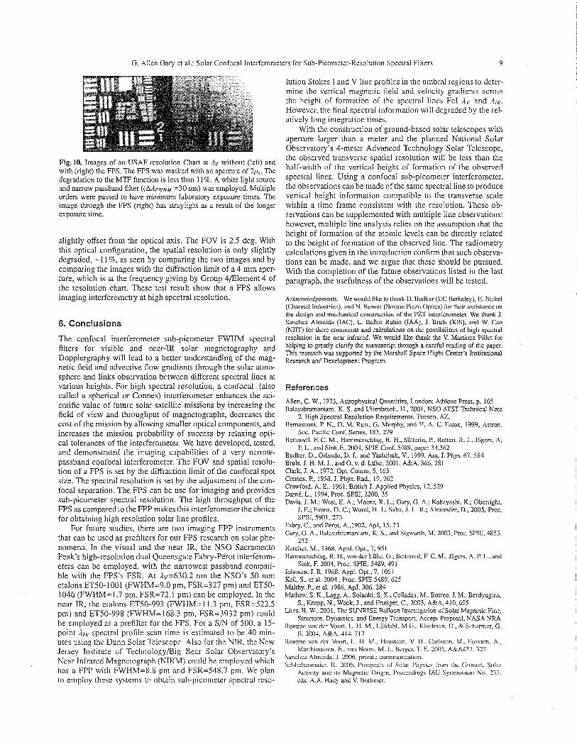
G. Allen Gary et a].: Solar Confocal Tnterferonlel .ers for Sub-Picorneter-Resolution Spectral Filters 9
lution Stokes T and V line profiles in the umbra1 regions to deter-
Fig. 10. Images of an USAF resolution Chart at ,lv without (left) and with (right) the FPS. The FPS was masked with an aperture of 2p,. The degradation to the MTF function is less than 11%. A white light source and narrow passband filter ((A/LFIIrHM =30 nm) was employed. Multiple orders were passed to have minimum laboratory exposure times. The image through the FPS (right) has straylight as a result of the longer exposure time.
slightly offset from the optical axis. The FOV is 2.5 deg. With this optical configuration, the spatial resolution is only slightly degraded, -1 1%, as seen by comparing the two images and by comparing the images with the diffraction limit of a 4 mm aper- ture, which is at the frequency giving by Group 4~Element 4 of the resolution chart. These test result show that a FPS allows imaging interferometry at high spectral resolution.
6. Conclusions
The confocal interferometer sub-picometer FWHM spectral filters for visible and near-TR solar magnetography and Dopplergraphy will lead to a better understanding of the mag- netic field and advective flow gradients through the solar atmo- sphere and links observation between different spectral lines at various heights. For high spectral resolution, a confocal (also called a spherical or Connes) interferometer enhances the sci- entific value of future solar satellite missions by increasing the field of view and throughput of magnetographs, decreases the cost of the mission by allowing smaller optical components, and increases the mission probability of success by relaxing opti- cal tolerances of the interferometer. We have developed, tested, and demonstrated the imaging capabilities of a very narrow- passband confocal interferometer. The FOV and spatial resolu- tion of a FPS is set by the diffraction limit of the confocal spot size. The spectral resolution is set by the adjustment of the con- focal separation. The FPS can be use for imaging and provides sub-picometer spectral resolution. The high throughput of the FPS as compared to the FPP makes this interferometer the choice for obtaining high resolution solar line profiles.
For future studies, there are two imaging FPP instruments that can be used as prefilters for our FPS research on solar phe- nomena. In the visual and the near IR, the NSO Sacramento Peak's high-resolution dual Queensgate Fabry-PCrot interferom- eters can be employed, with the narrowest passband compati- ble with the FPS's FSR. At Arr=630.2 nm the NSO's 50 mm etalons ET50-1001 (FWHM=9.0 pm, FSR=327 pm) and ET50- 1046 (FWHM= 1.7 pm, FSR=72.1 pm) can be employed. In the near IR, the etalons ET50-993 (FWHM=11.3 pm, FSR=522.5 pm) and ET50-998 (FWHM=168.3 pm, FSR=3932 pm) could be employed as a prefilter for the FPS. For a S/N of 500, a 15- point ,IlR spectral profile scan time is estimated to be 40 min- utes using the Dunn Solar Telescope. Also for the NTR, the New Jersey Tnstitute of Technology/Big Bear Solar Observatory's Near Infrared Magnetograph (NTRM) could be employed which has a FPP with FWHM=8.X pm and FSR=548.7 pm. We plan to employ these systems to obtain sub-picometer spectral reso-
mine the vertical magnetic field and velocity gradients across the height of formation of the spectral lines FeI Av and However, the final spectral information will degraded by ihe rel- atively long integration times.
With the construction of ground-based solar telescopes with aperture larger than a meter and the planned National Solar Observatory's 4-meter Advanced Technology Solar Telescope, the observed transverse spatial resolution will be less than the half-width of the vertical height of formation of the observed spectral lines. Using a confocal sub-picometer interferometer, the observations can be made of the same spectral line to produce vertical height information compatible to the transverse scale within a time frame consistent with the resolution. These ob- servations can be supplemented with multiple line observations; however, multiple line analysis relies on the assumption that the height of formation of the atomic levels can be directly related to the height of formation of the observed line. The radiometry calculations given in the introduction confirm that such observa- tions can be made, and we argue that these should be pursued. With the completion of the future observations listed in the last paragraph, the usefulness of the observations will be tested.
Ac!ao~vlrdgernents. We would like to thank D. Budker (UC Berkeley), E. Bickel (Channel Industries), andN. Benoit (Boston Piezo Optics) for their assistance on the design and mechanical construction of the PZT interferometer. We thank I. Sanchez Almeida (IAC), L. Bellot Rubio (IAA), J. Bmls (KIS), a id W. Cao (NJIT) for there comments and calculations on the possibilities of high spectral resolution in the near infrared. We would like thank the V. Martinez Pillet for helping to greatly clarify the manuscript through a careful reading of the paper. This research was supported by the Marshall Space Flight Center's Institutional Research and Development Program.
References
Allen, C. W., 1973, Astrophysical Quantities, London: Athlone Press, p. 165 Balasubramaniam, K. S. and Uitenbrock, H., 2001, NSO ATST Technical Notc
2, High Spectral Resolution Requirements, Tucson, AZ. Bemasconi, P. N., D. M. Rust, G. Murphy, and H. A. C. Eaton, 1999, Astron.
Soc. Pacific Coni. Series, 183,279 Bettonvil, F. C. M., Hammerschlag, R. H., Siitterin, P., Rutten. R. J., Jagers, A.
P. L., and Sink,F., 2004, SPIE Coni. 5489, paper 34.362 Budker, D., Orlando, D. J., and Yaslichuk, V., 1999, Am. J. Phys. 67, 584 Bruls, J. H. M. J.. and 0. v. d. Liihc, 2001, A&A, 366,281 Clark, J. A,, 1972, Opt. Comm. 5, 163 Connes, P., 1958, J. Phys. Rad., 19, 262 Crawiord. A. E.. 1961, British J. Applied Physics, 12.529 Dame, L., 1994, Proc. SPIE, 2200.35 Davis, J. M.; Wcsl, E. A,; Moorc, R. L.; Gary, G. A,: Kobayashi. K.; Obcnipht,
J. E.; Evans, D. C.; Wood, H. J.; Saba, J. L. R.; Alexander, D., 2005, Proc. SPIE, 5901.273
Fabry, C.. and Pirot, A.,1902, ApJ, 15,73 Gary, G. A., Balasubramaniam, K. S. , and Sigwarrh, M. 2003, Proc. SPIE, 48.53,
252 Hercher, M., 1968, Appl. Opt., 7, 951 Hammerschlag, R. H., von der Liihe. O., Benonvil, F, C. M.. Jdger~, A. P. L., and
Sink, F. 2004, Proc. SPIE, 5489,49 1 Johnson, J. R. 1968, Appl. Opt., 7, 1061 Keil, S., et al. 2004 , Proc. SPIE 5489, 625 Maltby, P., et al. 1986, ApJ. 306, 284 Mathew, S. K., Lagg, A,. Solanki. S. K., Colladas, M.. Borreo, J. M.. Berdyugina,
S.: b p p , N., Wock, J., and Frutiger, C., 2003, .4&A, 410, 695 Lites. B. W., 2001, The SUNRISE Balloon Invcstiga~ion oiSolar Magnctic Fine,
Structure, Dynamics, and Energy Transport, Accept Proposal, NASA NRA Rouppc van dcr Voorr, L. H. M., Loidahl. M.G., Kisclrnan, D., & Scbancr, G.
B. 200-f. A&A. 41A, 717 Rouppc van dcr Voon. I>. H. M., Hanstccn, V. H., Carlsson, M., Fossum. A,.
Marrhinussen, E., van Noon. M. J.. Berxer, T. E. 2005. A&A437. 327 Sanchez Almeida, J. 2006, private communication. SchIic1imniaie~-. R. 2006, Prospecrs of Solar Physics I'rom ~hr: G~ound. Solar
Activity and its Magnetic Origin, Proceedings IAU Symposium No. 233. cds. A.A. Hady and V. Hothnicr.

10 G. Allen Gary et al.: Solar Confocal Interferometers for Sub-Picometer-Resolution Spectral Filters
Solanki, S. K., Riiedi.1, andLivingsion, W., A,, 1991, A&A, 263,312 Stein, R. F., and Nordlund, A,, 2006, ApJ, 642, 1216 Stcnflo, J. O.,Ha~vcy, J. W., Brandt, J. W.,andSolanki, S . 198.1, A&A, 111.333 Vaughn, J. M. 1989, Tlte Fabry-Ptror Interferometer: History, Theory, Practice,
and Applications, Philadelphia: Adam Hilgcr