Embed Size (px)
Citation preview

Geotechnical Division
SOIL NAILS IN LOOSE FILL SLOPES
A preliminary study
Final Report January 2003
HONG KONG INSTITUTION OF ENGINEERS
香 港 工 程 師 學 會

HKIE Geotechnical Division Subcommittee – Soil nails in loose fill slopes Final Report – January 2003
DISCLAIMER This report has been prepared by a subcommittee appointed by the Geotechnical Division of the Hong Kong Institution of Engineers. It specifically addresses the issue of the suitability of using soil nails to enhance the stability of loose fill slopes in Hong Kong and suggests a design method for the use of soil nails in loose fill slopes. The report summarises the data and methodology on which these recommendations are based. A designer using the recommendations contained in this report does so entirely at his or her own risk. The Hong Kong Institution of Engineers does not accept any responsibility for the use or misuse of the report and the designer retains total responsibility for the adequacy of the design.

HKIE Geotechnical Division Subcommittee – Soil nails in loose fill slopes Final Report – January 2003
CONTENTS Executive Summary 1 Introduction 1.1 Background to the need for soil nails 1.2 The concern about soil nails in loose fill 1.3 The structure and scope of the report 2 Failures in loose fill slopes in Hong Kong 2.1 The 1976 Sau Mau Ping failure 2.2 The 1992 failure on Kennedy Road 2.3 Summary 3 Behaviour of loose granular soils 3.1 How much shear strain is required before the onset of collapse behaviour? 3.2 Is there volume change prior to collapse in dry loose soil? 3.3 Does partially saturated loose fill (soil) collapse in volume as it becomes saturated? 3.4 Summary 4 Experience worldwide of soil nailing in loose fill 4.1 Temporary works 4.2 Permanent works 5 Properties of loose fills in Hong Kong 5.1 Laboratory tests to study contractive and collapse behaviour of fill 5.2 Angle of internal friction at steady state 5.3 Shear strain at failure 5.4 Steady state strengths 5.5 Effects of partial saturation 5.6 Is loose CDG fill a special material? 6 Data on old fill slopes in Hong Kong 7 Stability calculations 7.1 Basis of the calculations and the assumptions 7.2 Design of soil nails 7.3 Design of the nail heads and surface grillage 8 Numerical modelling 9 Physical modelling 9.1 Laboratory element tests 9.2 Centrifuge modelling 9.3 Full scale field testing 10 Design recommendations References Appendix – Changes in recommendations from the November 1998 Draft Report Tables Figures


HKIE Geotechnical Division Subcommittee – Soil nails in loose fill slopes Final Report – January 2003 1
EXECUTIVE SUMMARY
There are several thousand loose fill slopes in Hong Kong. These have generally been in place for many years and usually predate the establishment of the Geotechnical Control Office in 1977. They were placed to form platforms for roads and other purposes and are now situated within the infrastructure of Hong Kong. There have been a few major failures of loose fill slopes and the Sau Mau Ping disasters in 1972 and 1976 showed the devastation that failure of a loose fill slope could cause. In both cases the failures were sudden with the failed material moving rapidly downhill in a semi-liquid-like state. There have been examples of similar rapid failures of slopes in natural material (e.g. the 1995 Fei Tsui Road landslide) but loose fill is observed to be more mobile and move further when it fails posing greater threat to life. It is a widely held opinion that the suddenness of the failure is due to the loose nature of the fill which leads to it attempting to compress on failing. The compression leads to a large rise in pore water pressure in the temporarily saturated material and leads to a further loss of strength and effectively a flow slide. The usual way of dealing with this hazard at present is to recompact the upper three metres of material in the slope. This should lead to an increase in shear strength, a reduction in permeability and a slower and more ductile response in the event of subsequent failure. Since 1976 many loose fill slopes have been treated by recompaction. However, in many cases this is difficult to implement and can be impossible to carry out which has led to the search for alternative methods of enhancing the stability of these slopes. Nails are commonly used in Hong Kong, particularly to enhance the stability of cut slopes in natural material, and the purpose of this report is to assess their possible use in loose fill slopes. A worrying aspect for the use of nails in loose fills is that when loose fills are subjected to shearing they may lose strength at such a rate that the forces mobilised in the nails will not be able to compensate for the loss of shear strength in the fill. To investigate this, strain compatibility could be considered to determine the stress state of the soil when overall equilibrium is assured. Alternatively, it can be assumed that by the time the nails are working as required the soil has already reached the minimum saturated steady state strength. This second approach has been adopted in this report. Provided that a conservative estimate of the soil steady state shear strength is used then this situation is the worst case that can exist for the soil. To determine the steady state shear strength of the loose fill use has been made of several series of undrained triaxial compression test results completed at the University of Hong Kong, the Public Works Central Laboratory and the Hong Kong University of Science and Technology. These tests show the steady state shear strengths for fill materials from several sites and for a range of void ratios and initial confining pressures. The results show that these materials behave much better than a clean sand in that the loss of strength is not as rapid. It must be emphasised that these tests have been carried out on remoulded material and therefore are conservative as they neglect any beneficial effects of strength improvement due to aging likely to present in existing loose fill slopes. Calculations using the steady state shear strength derived from the laboratory tests show that a significant number of nails are required to provide sufficient additional strength to that of the steady state soil shear strength. These calculations assume that there is a failure surface at some depth within the fill. The greater the depth to this surface the greater are the required nail forces. Improved surface protection and drainage measures are to be prescribed to reduce the likelihood of water ingress into the fill. What cannot be readily demonstrated however is how the nails would pick up adequate resistance in the material between the postulated failure surface and the slope surface. This has led to the conclusion that deep horizontal beams or a surface grillage are required to connect the nail heads together. The report also discusses the possibility of using physical and numerical models to further explore this problem with the aim of justifying a less conservative approach to the design of the nails. For either to be used with confidence it is recognised that large-scale trials are necessary to validate these methods. Design recommendations for soil nails in loose fill are presented for loose fill having at least 75% relative compaction. It is suggested that, provided adequate measures are taken to prevent surface erosion and provide drainage, the following procedure can be used:
HKIE Geotechnical Division Subcommittee – Soil nails in loose fill slopes Final Report – January 2003 2
1. Soil nails are not required if conventional slope stability analyses demonstrate that the minimum factor of safety currently specified in the ‘Geotechnical Manual for Slopes’ is achieved against the possibility of undrained collapse behaviour. Undrained triaxial compression tests on saturated remoulded samples of loose fill show that the lower bound shear strength before the onset of undrained behaviour can be represented by a φ’ value equal to 260. Material specific testing may show a higher result however. In the stability calculations positive pore water pressures should be used if a perched water table or phreatic surface is assessed to be a reasonable possibility. Otherwise zero pore water pressure would be assumed. This first step in the design process will generally mean that upgrading works will not be required on a slope that is less steep than about 200
if the slope is not subject to positive water pressures. 2. If nails are required, conventional design calculations with a minimum factor of safety of 1.1 with
the fill represented by its large strain steady state undrained shear strength, will be conservative. If site-specific laboratory testing is not carried out a conservative value of steady state undrained shear strength equal to 0.2 times the mean effective stress at the onset of undrained behaviour is recommended. It can be conservatively assumed that this is the mean effective stress that would exist in the slope assuming no suction pore pressure is present. If a perched water table or phreatic surface is assessed to be a reasonable possibility then positive pore water pressures should be used when determining the mean effective stresses. For a slope with no positive pore water pressures this results in an undrained shear strength to vertical stress ratio of about 0.13. Laboratory testing can be used to determine the undrained shear strengths and it is expected that these tests will show that undrained shear strengths of at least twice those implied by this ratio will be appropriate in many cases. The soil nails should be assumed to be at their ultimate tensile capacity under these conditions and the reinforcement quantity can be checked directly using BS8110. Guidance for deriving the steady state shear strength from site-specific laboratory testing is included in Section 10.
It is recommended that soil nails should be placed at a spacing of no greater than 2m horizontal and 1.5m vertical spacing. A surface grillage connecting the nail heads or some other structural surfacing will be required to ensure that all of the soil is effectively restrained against downslope movement. The grillage should extend about 0.5m below the fill surface to ensure good contact with the fill and it needs to be designed to be able to spread the predicted nail tensile forces across the slope surface. Calculations are presented to show how the required nail forces can be assessed and it is demonstrated that, in many cases, the nail capacity needs to progressively increase down the slope. The geometry of the grillage should be such that the loose fill material cannot squeeze out between the grillage beams. This could be achieved by limiting the opening area. The grillage beams must be able to span between the nails and to have sufficient structural capacity to ensure that the grillage behaves in a monolithic manner.

HKIE Geotechnical Division Subcommittee – Soil nails in loose fill slopes Final Report – January 2003
3
1 INTRODUCTION As part of the ongoing slope safety improvement effort in Hong Kong the Geotechnical Engineering Office (GEO) asked the HKIE Geotechnical Division to make recommendations on the use of soil nails to upgrade loose fill slopes. The HKIE Geotechnical Division set up a special committee to address the specific issue of the application of soil nails to enhance the safety of loose fill slopes. This report presents the findings of the special committee. The special committee comprised the following geotechnical engineers. Name Organisation Ir Dr Jack Pappin (Chairman) Arup Ir Raymond P.C. Chan Binnie Ir Dr John Endicott MGS Ir Albert Ho Arup Ir Ken Ho GEO Ir Prof. Tim Law HKU Ir Dr Charles W.W. Ng HKUST Ir Dr Matthew Raybould Scott Wilson Ir Prof. C.K. Shen HKUST Ir Dr H.W. Sun GEO This study followed a report prepared by Dr. B. Simpson for the GEO entitled “The use of soil nails to upgrade loose fill slopes” (Ove Arup and Partners, 1996). The report summarised the available information and concluded that while it is considered likely that soil nails would substantially improve the stability of slopes in loose fill there was not sufficient information to draw final conclusions. It also made recommendations for areas of further research including laboratory testing, field trials and model tests. The study by Simpson was based on published literature and could only draw on experience with loose sand material. As will be shown later in this report, the study presented here has had the opportunity to draw on the results of extensive laboratory studies on loose CDG fill. These tests comprised a large part of the laboratory testing recommended by Simpson. The first draft of this report was published for comment in November 1998. It made recommendations for a design method for soil nails in loose fill. Many comments were received and the report has been revised to take account of most of these comments. In the intervening period many more laboratory tests results have also become available and this final report also incorporates these additional test results. The key differences in recommendations between the draft report published in November 1998 and this report are summarised in the Appendix.
1.1 Background to the need for soil nails There are several thousand sizeable loose fill slopes more than 3m high in Hong Kong. These have generally been in place for many years and usually predate the establishment of the Geotechnical Control Office in 1977 (renamed Geotechnical Engineering Office in 1991). They were placed to form platforms for roads and other purposes and are now situated within the infrastructure of Hong Kong. As described in Chapter 2 of this report there have been several notable failures of loose fill slopes. The Sau Mau Ping disasters in 1972 and 1976 showed the devastation that failure of a loose fill slope could cause. In both cases the failures were sudden with the failed material moving rapidly downhill in a semi liquid like state. There have been examples of similar rapid failure of slopes in in-situ material (e.g. the 1995 Fei Tsui Road landslide) but it has been observed that natural insitu material does not flow out as far for the same scale of failure, thus posing less threat to life. Following the 1976 Sau Mau Ping failure, an Independent Review Panel for fill slopes was set up. They concluded that the suddenness of the failure was due to the loose nature of the fill which led to it attempting to compress on failing giving rise to a large rise in pore water pressure in the temporarily saturated material which caused a further loss of strength and effectively a flow slide

HKIE Geotechnical Division Subcommittee – Soil nails in loose fill slopes Final Report – January 2003
4
(Hong Kong Government 1977). They went on to recommend that this phenomenon could be alleviated by excavating and recompacting the upper three metres of material. This would lead to a slower and more ductile response in the event of subsequent failure. Recompaction would also enable the presence of water-bearing services in the slope to be checked and repositioned if possible. Since 1976 many loose fill slopes in Hong Kong have been treated by recompaction. This often causes great practical difficulty however because it can lead to significant disruption, can be very difficult and dangerous to implement and frequently requires the destruction of mature vegetation. In some instances it is deemed to be impossible to carry out recompaction and the slope remains untreated. This has led to the question being asked as to whether there are alternative methods of enhancing the stability of loose fill slopes. One possible alternative is to use soil nails. Soil nails are commonly used in Hong Kong particularly to enhance the stability of existing cut slopes and sometimes to create new cut slopes. Clearly the locations of water-bearing services would still need to be checked but this could be readily achieved by using trenches up the slope in suitable and convenient locations, possibly augmented by geophysical methods.
1.2 The concern about soil nails in loose fill A worrying aspect of loose fills is that when they are subjected to shearing they may exhibit a peak shearing resistance followed by a reduction in shearing resistance as shearing displacement occurs. The effective stress path and the shear capacity versus shear displacement relationship for a loose cohesionless soil on the failure surface are shown in Figure 1.1. Loose fill slopes are likely to comprise materials that are typically partially saturated and maintain a suction. Shear stresses are present in the ground but as these are less than the available shearing resistance, equilibrium is sustained. Any point in the fill slope would be at equilibrium (shown as Point A in Figure 1.1). With water ingress into the fill the degree of saturation increases. Assuming there is sufficient water ingress and that the slope is steep enough the pore pressure suction reduces in a drained manner until Point B is reached. From the results of stress path testing in the laboratory it is likely that the shear strain induced in the soil at this stage is small. At Point B the shear strength of the soil is no longer able to provide equilibrium and the shear strain begins to increase causing undrained shearing to occur. The material strength then reduces until the steady state strength is reached at Point C. Figure 1.2 shows the same situation as Figure 1.1(b) together with the applied shear stress plotted against shear displacement. The applied shear stresses are shown to increase slightly as a result of the increase in weight due to water ingress. As can be seen, if Point B is reached the slope is in a situation of incipient failure because a marginal increase in shear displacement will result in a reduction of shearing resistance. It is possible that failure will occur either in a narrow band as a rupture surface on which failure by sliding can rapidly develop or as a zone of significant thickness within which the soil can flow giving rise to the description ‘liquefaction’. Where a potential sliding surface or zone can be identified, soil nails can be installed to pass through the sliding surface with an anchorage to either side as shown in Figure 1.3. Sufficient nails need to be installed such that the combined resistance of the soil and the nails provides the required factor of safety against failure. As shown diagrammatically in Figure 1.3, if the resolved disturbing forces of the soil above the potential sliding zone is D and the resolved resistance of the soil is RS and the resolved resistance of the soil nails is RN, then (RS+RN)/D should be equal to or exceed the required factor of safety. Soil nails are installed without any preload. If the soil slope develops shear displacement the soil nails will develop their resistance correspondingly. Figure 1.4 shows diagrammatically how the soil shearing resistance, RS develops from the initial condition (as represented for one Point by A in Figure 1.2) as downslope displacement occurs. Similarly the resistance provided by the soil nails, RN, is plotted as is the combination RS+RN. When the combined effects of soil shearing resistance and resistance to sliding provided by the soil nails exceed the requirements of equilibrium of the slope by an adequate factor of safety, failure will not occur.

HKIE Geotechnical Division Subcommittee – Soil nails in loose fill slopes Final Report – January 2003
5
1.3 The structure and scope of the report
The report is arranged as follows: Chapter 2 - discusses the history of failures of loose fill slopes in Hong Kong and the evidence for
flow slides. Chapter 3 - presents the laboratory evidence for the collapse potential of loose granular soils both
in the saturated and partially saturated condition. Chapter 4 - gives a brief overview of the use of nails in loose soils in the world and Hong Kong. Chapter 5 - discusses the properties of loose fills in Hong Kong and examines whether they are
special materials. Chapter 6 - presents data on the range of loose fill slopes existing in Hong Kong. Chapter 7 - presents a series of conservative calculations that aim to establish the quantity of soil
nails required to stabilise a typical loose fill slope. Chapter 8 - discusses the merits of numerical modelling in exploring and understanding the
problem such that a less conservative approach could be used. Chapter 9 - discusses the role of physical modelling in verifying the recommendations. Chapter 10 - presents an interim set of conservative guidelines for the design of soil nails in loose
fill slopes. The report only investigates the issue of whether the presence of soil nails in a loose fill slope can reliably increase the safety of that slope. It does not discuss the issues of how to construct soil nails in loose fill. Durability of soil nails is also not discussed.

HKIE Geotechnical Division Subcommittee – Soil nails in loose fill slopes Final Report – January 2003
6
2 FAILURES IN LOOSE FILL SLOPES IN HONG KONG There are several case histories of loose fill slope failures in Hong Kong that involved flowslides. Table 2.1 presents a summary of the major failures in loose fill slopes considered by the GEO to have experienced a flowslide. Figure 2.1 shows an accompanying diagram from the GEO that shows the travel angle (defined as the angle from the crest of the slope to the toe of the debris after the failure has stopped) against the volume of failed material. Clearly there is an expected trend for larger slides to flow out to a shallower angle and therefore be more mobile than the smaller slides. The dynamics of the mass would tend to lead to this effect. There is also evidence however that the slides which have experienced a flowslide (or liquefaction) or a major washout type failure have tended to run out further than the corresponding cut slopes and fill slopes where a conventional sliding type failure took place. For the purpose of this report two of the failures are described in some detail to illustrate the nature of the problem that is being addressed by this report. These are the Sau Mau Ping failure in 1976 and the Kennedy Road failure in 1992.
2.1 The 1976 Sau Mau Ping failure A section through this failure is shown in Figure 2.2. As can be seen it involved a slope with a height of greater than 30m. The original slope angle was 33°. The failure was quite shallow, being about 2 metres thick on average (locally up to 4m thick), with the debris running out to flow into and engulf the lowest storey of the adjacent tower block, Block No. 9. Figure 2.2 also shows the great thickness of fill at the site extending up to about 25m thick. There are various features about the Sau Mau Ping landslide that make it somewhat exceptional and may have significance to its failure. There is good circumstantial evidence that there were construction difficulties because the crest of the slope never achieved the desired line as shown in Figure 2.3. Also when the slope was reinstated extensive under-drainage measures and over excavation were required to overcome stability problems as shown in Figure 2.4. Maps of the area, made before the slope was constructed, show that there was a significant stream course at this location. Even with these measures there were still many springs coming out of the face of the slope, as shown in Figure 2.5, implying a large supply of ground water coming up from beneath the slope. This later evidence leads to the question as to whether rising ground water could have had a significant contribution to the failure in 1976. If this had been the case however, it would be difficult to understand why a deeper failure did not occur.
2.2 The 1992 failure on Kennedy Road A section through this slope is shown in Figure 2.6. As can be seen the original slope was very steep standing at about 35° on average and much steeper at its toe. In the failure the upper 2 metres of material moved down the slope and across the road burying a car. Some debris remained on the slope above the road however. Given the height and steepness of the underlying insitu material it may be possible that the extent of debris runout could have occurred without significant build up of excess pore water pressure.
2.3 Summary It is observed that failure can occur in loose fill slopes leading to significant runout of the failed material. These failures can be dramatic and potentially occur suddenly with little prior warning.

HKIE Geotechnical Division Subcommittee – Soil nails in loose fill slopes Final Report – January 2003
7
3 BEHAVIOUR OF LOOSE GRANULAR SOILS As discussed in Chapter 1, soil nails are passive elements and they will be unstressed for most of the time. In the event of the slope wetting up in a rainstorm situation and therefore attempting to move the nails will become stressed as a result of shear strain in the fill. Figure 1.4 illustrates this build up of force in the soil nails. It is of concern to the designer whether this build up of forces in the soil nails tends to occur as the soil is losing strength or after the soil has reached its minimum steady state strength. The former will lead to a more controlled behaviour of the slope whereas the latter could lead to a brittle type response where the nails become effective only after the soil already reached its minimum steady state strength condition. The above question is complex and it has been divided into three parts. These are
1. what shear strain is required in a saturated soil to develop a possible collapse, 2. what volume change occurs prior to collapse in a dry soil and 3. what is the collapse behaviour of a partially saturated soil.
Both the shear and volume change behaviour of the fill prior to collapse are important as they combine to influence the tensile strain that will be induced in the soil nails.
3.1 How much shear strain is required before the onset of collapse behaviour? Based on laboratory triaxial element tests on fully saturated loose sands, the existence of a “collapse surface” in the three-dimensional space of mean effective normal stress (p’) by deviatoric shear stress (q) by void ratio (e) has been demonstrated by many researchers (Sladen et al. 1985, Sasitharan et al. 1993, Skopek et al. 1994). Loose sand specimens collapse when the collapse surface corresponding to a particular void ratio is reached. The strain required to reach the collapse surface is typically quite small. Figure 3.1 shows the deviator stress-axial strain responses of saturated Ottawa sand during constant deviator stress drained tests. It can be seen from the figure that the axial strains at failure are less than 1% and that the mobilised angle of friction at collapse (φ′m=19.90) is significantly smaller than the steady-state angle, φ′CRIT = 30.60. Recent similar constant deviator stress tests (see Figure 3.2) on loose remoulded CDG specimens obtained from Shau Kei Wan (SKW) carried out at HKUST also reveal collapse behaviour at less than 1%. However, the mobilized angle of friction at collapse ranging from 31.80 to 38.70, which is significantly higher than the instability angle (28.10) obtained from isotropically consolidated undrained triaxial compression tests, but it is less than φ′CRIT = 38.70 of the CDG (Ng et al. 2002a). This implies that the assessment of the margin of safety against possible undrained failure based on isotropically consolidated undrained tests would be conservative. It has been reported by DiPrisco et al. (1995) that a soil specimen subjected to pre-shearing in drained conditions (Point B in Figure 3.3) can sustain larger strains than a specimen with little or no pre-shearing. As shown in Figure 3.3 after reaching Point B, the pre-sheared specimen responded to undrained loading in a less brittle manner than a specimen with little or no pre-shearing. The soil specimen sustained a relatively higher deviatoric stress (about 100kPa) for an additional 4% of axial strain. While the change of void ratio during the pre-shearing stage was not reported, volume strains are shown for tests with similar drained stress paths. These show the volumetric strain would probably have reached about 3% at Point B. By interpreting the axial strains shown in the figure, it would be rather difficult to tell the increased shear strength due to the effects of pre-shearing (i.e. reduction of void ratio) during the drained pre-shearing stage quantitatively. It should be noted that shear strain is three times greater than the axial strain in the undrained test path (from B to C’’ in Figure 3.3), which means the pre-sheared samples behave in a relatively ductile manner. This leads to the strong possibility that soil nails would mobilise their strength before the soil strength has reduced to the steady state value. Figure 3.4 shows anisotropically consolidated undrained tests on loose CDG samples taken from SKW. In contrast to the test results shown in Figure 3.3, the post peak strength behaviour of the CDG becomes slightly more brittle manner as the initial stress ratio, ηc=q/p′ increases.

HKIE Geotechnical Division Subcommittee – Soil nails in loose fill slopes Final Report – January 2003
8
3.2 Is there volume change prior to collapse in dry loose soil? Skopek et al. (1994) reported a series of tests on loose dry Ottawa sand (prepared at a 2.5% moisture content). The triaxial tests were conducted by keeping the deviatoric stress q (= σ’V - σ’R ) constant and reducing the mean effective stress p’ (= [σ’V + 2*σ’R]/3) as shown in Figure 3.5. It is evident from the figure that the soil collapsed at a mobilised angle of internal friction, φ’, ranging from 15o to 18o. This is far less than its constant volume angle of friction value, φ’CRIT, of 30o. At the collapse, significant volume changes took place with about 10% volumetric strain being developed. Prior to collapse, there is very little volumetric strain with a corresponding axial strain of about 0.8% and a small amount of radial strain. The corresponding shear strain developed was in the same order of magnitude as the axial strain and there is very little volumetric strain. This implies that the soil nails should be developing load prior to the onset of collapse behaviour of the soil.
3.3 Does partially saturated loose fill (soil) collapse in volume as it becomes saturated? The behaviour of partially saturated soil is more complex than that of saturated soil. According to Wheeler & Sivakumar (1995), four state variables are needed to describe soil behaviour. These four variables are net mean stress p = (σ1+ σ2+ σ3)/3 - uA, deviator stress q, suction s = uA - uW, and specific volume v (where uA and uW are the pore air and water pressures respectively). Wheeler & Sivakumar (1995) used a triaxial apparatus with suction control to study volume changes of a recompacted clay at various equalisation stages (see Fig. 3.6), during which specimens with initial high suction (about 470kPa) were wetted (i.e. reduction in matrix suction) to various lower controlled suctions (s = 0, 100, 200 and 300kPa). During the wetting process, the isotropic stress was kept constant (i.e. constant p) and volume changes were measured. It was found that the pattern of swelling and collapse observed during wetting was governed by the stress state on the p-s plane in relation to the location of the yield curve. For specimens C0 and C1 (which are virgin materials), that crossed the yield curve, collapse behaviour was observed and this could not be explained by the conventional principle of effective stress for saturated soils. Virgin materials are defined as soils that have not been subjected to a suction greater than the current suction value (Ng et al. 1998). For specimens C2 and C3 (which are not virgin materials), which stayed inside the yield curve during wetting, swelling occurred. The results of these tests suggest that an unsaturated specimen can be either contractive or dilative during wetting, depending on its current stress state in relation to the yield surface. The implication is that suction forces do not act in the same way on the soil skeleton as an applied external mean effective stress p’. The suction forces must act to hold the individual particles together whereas increasing p’ acts to increase the interparticle compression forces. Therefore there is a tendency for volume collapse to occur as wetting progresses even without any shear stresses being present. Fredlund & Rahardjo (1993) studied the swelling and collapsible behaviour of loose silty and sandy materials subjected to one-dimensional inundation using modified oedometers with suction measurements. It should be noted that shear stress is also induced to soil specimen during a one-dimensional test. They identified the existence of two types of soil structure for unsaturated soils: stable-structure and meta-stable structure (see Figures 3.7 and 3.8 respectively). Their findings, which are mainly based on one-dimensional inundation tests, are consistent with the observations made by Wheeler & Sivakumar (1995) during their tests involving isotropic wetting. Some one-dimensional inundation tests on the same Hong Kong loose fills have been conducted (Chiu et al. 1998 and Ng et al. 1998) and similar results were obtained (see Section 5.6). Figure 3.9 shows test results on undrained CDG samples obtained from Cha Kwo Ling subjected to various constant deviator stresses and net mean stresses (p) but at reducing soil suctions (Ng & Chiu, 2002). It can be seen that all the four soil specimens fail when the soil suction reduces. The soil suction at failure depends on the p values. Generally, the soil can sustain a larger reduction of soil suction under higher p. During the process of suction reduction, both contractive and dilative behaviour can be seen. The higher the net mean stress, the larger the tendency to dilate. The mobilised axial strain at failure is significantly larger than the corresponding volume strain. This implies that the mobilised shear strain at failure is also very large and suggests that the unsaturated soil behaves in a ductile manner during the suction reduction stress path. Therefore, it is likely that non-virgin unsaturated CDG will permit soil nails to develop their tensile stress prior to failure.

HKIE Geotechnical Division Subcommittee – Soil nails in loose fill slopes Final Report – January 2003
9
3.4 Summary
Both contractile (collapse) and dilative behaviour can be observed in loose unsaturated sands and CDG, depending on the void ratio state relative to the steady state curve. Collapse behaviour of virgin loose materials is primarily related to the reduction of matric suction. The amount of 1 dimensional collapse of partially saturated loose sands is primarily a function of initial moisture content (or matrix suction) and initial density. Large shear strains could develop during inundation and shearing. The mobilized angle of friction of loose saturated remoulded CDG at the onset of undrained collapse during shearing under constant deviator stress with reducing mean effective stress is noticeably higher that obtained from isotropically consolidated undrained triaxial compression tests.

HKIE Geotechnical Division Subcommittee – Soil nails in loose fill slopes Final Report – January 2003
10
4 EXPERIENCE WORLDWIDE OF SOIL NAILING IN LOOSE FILL It is beyond the scope of this report to give a comprehensive review of the past experience around the world. Conference proceedings reporting on the current application of soil nailing including Earth Reinforcement, published by Balkema in 1996, Ground Improvement Geosystems Densification and Reinforcement, published by Thomas Telford in 1997, Ground Improvement Journal (1998), Foundation Engineering (1989) by F. H. Kulhawy, et. al. have been reviewed however. Cases of soil nailing being used in Hong Kong, UK and USA have also been sought. In the recent past, a composite system of soil nails and vertical reinforcing elements at the face were used successfully in the Seattle area, Washington. Typical vertical reinforcing elements are 150 to 200mm diameter pipe piles that are installed in drilled holes and grouted with lean grout mix. As the excavation proceeds, soil nails are installed adjacent to the vertical piles. These are mainly for supporting vertical excavations for buildings, underground parking and highway cut. In addition to providing enhanced face stability, the vertical elements provide cantilever support for the uppermost loose soils. A proprietary Venis system has been developed and used in Seattle area in the past couple of years for temporary and permanent shoring. This system consists of traditional soil nails, vertical steel bars in a 6-inch diameter hole or pipe piles in 8-inch diameter holes at the face, and pipe walers connecting the piles at various locations as the construction proceeds. The soil nails are installed between the piles. This system is claimed to be more economical than the composite system mentioned above. Depending on the soil conditions, the spacing of the vertical elements is as low as 1m. A summary of case studies is given on Table 4.1.
4.1 Temporary works The use of soil nails in loose fill for temporary works is not directly addressing the principal question being addressed in this report regarding the reliability of their behaviour in severe rainstorms. However other issues including the practicality of installation and associated effects such as ground movement are relevant. Evidence of the use of soil nails to stabilise temporary works excavations is mainly anecdotal, and as expected little is formally reported. Some examples are given below. In Hong Kong, a 20m high temporary cut slope in fill adjacent to a live carriageway has been supported by a combination of soil nails and ground anchors. The fill type is described as gravelly clayey sand with cobbles and boulders with SPT values typically less than 10 (Gammon, HK).
In the UK, soil nails were used to stabilise a 5m high temporary cut in shraff (ash and other waste from pottery industry) to facilitate cut and cover tunnel construction (Scott Wilson, UK). Also in the UK, Martin (1997) describes the stabilisation of poor embankment fill by 8m long soil nails on a 1m x 1m grid to facilitate a 10m high vertical cut. Ingold & Myles (1996) describe the application of ballistic soil nailing to stabilise a clay fill embankment undercut by a stream course, 5m long nails were installed to underpin the road pavement prior to permanent stabilisation works. In the USA, there were several applications of composite and Venis systems in the recent past. However, these applications were where upper soils are loose material and lower soils are competent. Two cases were as follows:
• Legacy Towers project in Seattle, Washington used a temporary Venis system for shoring in 1999. The total excavation depth was about 15m. The upper soil was loose fill material. Perched water was present in the fill.
• Centennial Court Project in Seattle, Washington, used a temporary composite shoring system in 1999. The upper soil was loose fill. The depth of excavation was in the order of 6m.

HKIE Geotechnical Division Subcommittee – Soil nails in loose fill slopes Final Report – January 2003
11
4.2 Permanent works Evidence for permanent works in fill materials is widely reported with experience in most continents (e.g. examples of soil nailing to form both steeper slopes and vertical faces in existing embankments slopes are widely reported, particularly in Japan). Reported cases of permanent soil nailing in loose fill are much fewer, however and some examples are given below:
• Martin (1997) describes the stabilisation of a 32o slope formed of poorly compacted fill material by “pinning” the loose fill veneer to the underlying stiff boulder clay. Drilled and grouted soil nails 10m to 14m in length were installed on a 2.5m by 2m grid.
• Drumm et al. (1997) describe the preliminary phases of a project to remediate unstable or marginally stable waste-rock (shale chips, sandstone fragments and coal) slopes formed from mine spoil. The project comprises monitoring the performance of an existing embankment on sidelong ground with an of overall slope height about 12m and a slope angle of 45o.
• Drumm et al. (1998) describe a project to remediate unstable or marginally stable waste-rock slopes that were created by dumping waste material downslope in Southern Appalachian Mountains of US. These materials consist of clay particles to boulders and often include trees and stumps. The overall slope height was 8 m with mine waste in the upper 4m to 4.6m. The lower material is clayey silt. The upper mine waste slope was at 45 degrees angle and it was stabilized with 3m long nails spaced at about 1.5m. The lower clayey silt material was cut at a 1H to 3.7V slope and nailed with 2.7m to 5.8m long nails.
• In the USA, the Spinner Building Project in Bellevue, Washington, used a permanent Venis system for ground support. Upper material was loose material and the lower material was glacial till.

HKIE Geotechnical Division Subcommittee – Soil nails in loose fill slopes Final Report – January 2003
12
5 PROPERTIES OF LOOSE FILLS IN HONG KONG Fill slopes in Hong Kong are commonly built of completely decomposed granite (CDG) or volcanic (CDV) material. Recent laboratory tests on some loose saturated CDV specimens (see Figure 5.1) with void ratios ranging from about 0.85 to 1.0 suggest that CDV has a strong tendency to dilate when it is subjected to undrained shearing (Ng & Chiu, 2000). As CDG is more often used and its post-peak behaviour may be very contractive in nature (Law et al., 1997; Ng & Chiu, 2000; Ng et al., 2002a), the following discussion is limited to CDG. This material is basically a granular soil with relatively high fines content. Its mechanical behaviour, therefore, bears some similarities as well as differences compared to that of clean sand. In this report, only the behaviour of the material in its loose state is described. Loose saturated CDG is contractive and possesses a structure that might lead to “work softening” and can reach its peak shear strength at a relatively low shear strain. This is in general similar to loose sand behaviour. The available information suggests that the steady state and collapse surface concept is applicable to both clean sand and to CDG. In detail, however, there are some differences between the two materials. Clean sand tends to be made up of rounded to sub rounded particles having a similar size. CDG is derived from the weathering of granitic rocks and consists of angular particles that contain a significant amount of silt and clay size particles, generally referred to as fines. The fines content may be as high as 50% and some may be bonded together. The presence of fines will modify the behaviour of the material as compared to that of clean sand.
5.1 Laboratory tests to study contractive and collapse behaviour of fill
A summary of some triaxial test results on loose remoulded CDG samples from Hong Kong (Law et al. 1997) is shown in Table 5.1 and in Figures 5.2 to 5.5. The materials had a fines content ranging from 18% to 39%. The relative compaction varied from 75% to 85% of the standard Proctor maximum dry density. The samples were prepared by mixing soil samples with water at the optimum moisture content. The mixture was put in a closed container for 24 hours. The moist tamping technique was then applied to form a triaxial test specimen. Saturation was carried out by passing carbon dioxide through the specimen for about 20 minutes followed by de-aired water. This process produced B values consistently exceeding 99% at a backpressure of 50kPa. The specimens were tested in a triaxial apparatus in an isotropically consolidated undrained manner. A consolidation pressure range of 25kPa to 400kPa was used. Some of the test results are shown in Figures 5.2 to 5.5. The soil samples clearly display “strain softening” behaviour. In this respect, saturated loose CDG behaves in a similar manner as saturated loose clean sand. It must be noted that the stress paths used in this series of tests do not follow that which will occur in a slope. As shown in Figure 1.2 an element of soil in a slope will be subjected to an almost constant shear stress with the mean effective stress, p’, reducing because of water ingress. This would lead to a drained behaviour followed by an undrained phase if the p’ reduces sufficiently such that the peak strength is reached. Previous work by other researchers using a constant shear stress path give conflicting results. The work by Sasitharan et al. (1993) (see Figure 3.1) and Skopek et al. (1994) (see Figure 3.5), both on Ottawa Sand, showing dramatic volume contraction prior to the sample reaching the steady state line. Riemer & Seed (1997), however, report that no significant volume reduction occurs before the steady state line is reached. Recent triaxial tests on CDG revealed that collapse behaviour does not tend to occur until the stress state is quite close to the steady state line (see Figure 3.2). For the purposes of this study the conservative interpretation that volume contraction, which will lead to pore pressure increase in a saturated soil, will occur prior to the steady state line being reached.

HKIE Geotechnical Division Subcommittee – Soil nails in loose fill slopes Final Report – January 2003
13
5.2 Angle of friction at steady state The values of the angle of friction, corresponding to the steady state of the tested CDG, φ’CRIT, are listed in Table 5.1. The values range from 36o to 40o with lower φ’CRIT being associated with higher fines content. These values are similar to those of angular, uniform to well graded loose sand but higher than those of rounded, uniform to well graded loose sand. This is understandable as the soil grains in CDG are quite angular. Figure 5.6 plots the steady state strengths, expressed in terms of deviatoric stress qSS, against the mean effective stress p’SS at steady state. In addition to the test results described by Law et al. 1997 this figure also shows results from additional testing carried out at the University of Hong Kong (HKU) and from a duplicate set of tests carried out by the Public Works Central Laboratory (PWCL) of the HKSAR. These duplicate tests were carried out on samples from Valley Estate, Diamond Hill and CLCY (Chi Lin Ching Yuen). It can be seen that there is generally reasonable agreement between the tests done at HKU and those done at PWCL. There are also data shown from other materials tested more recently by PWCL, including Ho Man Tin, Stubbs Road and Lai Ping Road. There are also results for two materials tested at the Hong Kong University of Science and Technology (HKUST), shown as Shau Kei Wan and Beacon Hill. It should be noted that all these materials are CDG except Lai Ping Road that is a CDV material. Figure 5.6 shows that the steady state angle of friction, φ’CRIT, is very similar for all the materials tested.
5.3 Shear strain at failure The axial strain at which the soil specimens reach its peak strength value in undrained triaxial compression tests is, in general, less than 2% (see Figures 5.2 to 5.5). This is considered low though it is slightly higher than that of loose clean sand. Loose soils will tend to behave in a stiff manner under a constant shear stress path that will occur as a result of water ingress into slope. The practical implication of this is that there could be little warning before a landslide occurs.
5.4 Steady state strengths According to the steady state concept the steady state line projected on an e - log p’ plane can be represented by: e = Γ - λ ln p’
where e is the void ratio, p’ is the mean effective stress = ( σ’1+ σ’2+ σ’3) / 3 Γ and λ are constants. The steady state condition can be shown on an e - log p’ plot as shown in Figure 5.7. Like clean sand, a line can be drawn to show the relationship between e and mean effective stress at steady state. If the stress state of a soil is on this line, there is no tendency for change in volume during shear deformation. However, if the state is above or to the right of this line, the soil will either contract under drained shear, or positive pore water pressure will be developed under undrained shear. On the other hand, if the state is below or to the left of the line, the soil will either dilate under drained shear or negative pore water pressure will be generated under undrained shear. The high fines content gives CDG a higher compressibility than clean sand at the same pressure. This increased compressibility is reflected in an increased value of λ. It can be seen from Figure 5.7 that the slope, or λ value, of the steady state line is similar for all of the materials. The λ values for six of the CDG samples from different sites are shown in Table 5.1. Table 5.2 gives a summary of λ values for some clean sands reported by Sasitharan et al. (1994). A comparison of the data shows that the λ values for CDG are 2 to 4 times larger than those for clean sands. The λ value denotes the rate of change of steady state strength to change of void ratio. The larger the λ value, the larger is the change of void ratio for a given change in the steady state strength. This leads to an important practical implication. For estimating the insitu steady state strength from

HKIE Geotechnical Division Subcommittee – Soil nails in loose fill slopes Final Report – January 2003
14
a knowledge of the void ratio, an error in the void ratio will produce a smaller error for CDG than for sand. Hence it is easier to determine the steady state strength of CDG. However, in spite of this favourable condition the accurate measurement of the insitu void ratio is still a very important step in characterizing the strength of CDG. It can be seen from Figure 5.7 that while each material individually shows a reasonable e - log p’ relationship the lines vary significantly from one material to another. The data shown in Table 5.1 show that this difference cannot be readily correlated to fines content or relative compaction. To explore these differences further the steady state shear strengths, cSS, have been plotted against various parameters. Figure 5.8 shows the steady state strength plotted against void ratio where it can also be seen that there is no systematic relationship between steady state shear strength and void ratio. Figure 5.9 shows a similar plot with the steady state shear strength being plotted against relative compaction. As can be seen, while there is general consistency within each of the test series, there is no overall trend. It is notable, however, that the strength increases noticeably at relative compaction values greater than 90%. The results for steady state strength have also been plotted against the mean effective stress, p’, value corresponding to the peak shear strength. This p’ value represents the stress Point B in Figures 1.1 and 1.2 and is the point at which the fill behaviour changes from drained to undrained in a possible failure scenario. For the purposes of this report this p’ value is referred to as p’peak. The results are shown in Figure 5.10 where it is seen there is a reasonable correlation between cSS and the p’peak values. If the “design line” shown on the figure of cSS/p’peak of 0.4 is used then the only data set that falls below it is the Valley Estate data while the remainder consistently plot above it. To allow for the Valley Estate data a more conservative “design” value of cSS/p’peak of 0.2 is required. The observed ratios of steady state strength to mean effective stress p’peak are plotted against relative compaction in Figure 5.11. For all materials it can be seen that this ratio increases slightly as the relative compaction value increases. The difference between the Valley Estate data and the other materials is also very evident from this figure. It must be realised that these laboratory data are for material having relative compactions in the range of about 75% to 95%. Looser fill material can exist and it is possible to prepare samples having a relative compaction as low as 70%. Another important finding from the laboratory testing is the peak soil shear strength. This is important because if it can be shown that the slope is not steep enough to mobilise this strength then the possibility of undrained movement is removed. In other words if the slope is flatter than a certain critical geometry then there will be no tendency for it to fail and soil nails, or any other form of stability enhancement, will not be required. Figure 5.12 shows the results for the peak strength in terms of qpeak plotted against p’peak. The results are seen to be quite similar for all materials with a conservative failure line that can be defined by a φ’ value of 26 degrees.
5.5 Effects of partial saturation While the general behaviour of CDG is similar to that of clean sand in the saturated state, there are significant differences in the unsaturated state. The differences stem largely from the substantial capacity of CDG to sustain matrix suction. Three aspects are briefly mentioned here. First, the shear strength of unsaturated CDG has a cohesive component while sand is a purely frictional material. The cohesion comes from two sources, clayey particles in the soil and matrix suction. The suction increases the effective stress without changing the total stress acting on the soil. The magnitude of the cohesion is therefore dependent on the magnitude of suction. Second, the steady state line in e-log p′ is higher for unsaturated CDG than for saturated CDG. Figure 5.13 illustrates this point by means of the King’s Park CDG (Law et al. 1997). The steady state line for the unsaturated soil, whether expressed in terms of the total pressure or taking the matrix suction into account, is higher than that of the saturated soil. In a certain region of stress space, therefore, a soil element may be at a stress point below the steady state line of the unsaturated soil but above the steady state line of the saturated soil. If the soil element is initially unsaturated, its behaviour is dilative and will be very unlikely to fail in a sudden flow slide. If by some means,

HKIE Geotechnical Division Subcommittee – Soil nails in loose fill slopes Final Report – January 2003
15
such as rainwater infiltration, the soil element becomes saturated, its behaviour becomes contractive, and its potential to flow sliding will be increased. Recent tests on unsaturated loose CDG specimens obtained from Cha Kwo Ling (Ng & Chiu, 2002) illustrate that soil suction ranging up to 33kPa only has some marginal effects on apparent cohesion but it does not have any effect on effective angle of friction (see Figure 5.14). Similar results were obtained from tests on loose CDV (Gan & Fredlund, 1996; Ng & Chiu, 2001). Figure 5.15 shows the variations of apparent cohesion (µ(s)) with soil suction. It can be seen that although µ(s) increases with suction up to about 80kPa, it reaches a plateau between suctions between 80kPa and 170kPa. As the suction further increases, in fact, the apparent cohesion may decrease. Third, aggregation of the clayey particles may be maintained after excavation and placement in a fill slope. These aggregations will have a higher strength than the CDG material after becoming completely remoulded. However, it is not clear if this phenomenon can continue to exist once the soil is fully wetted which could further increase the brittleness of the response.
5.6 Is loose CDG fill a special material?
As stated above laboratory test results for CDG material show similarities to that of clean sand and also some important differences. To explore the question of whether CDG is a special material reference has been made to some recent one-dimensional inundation experiments on granitic colluvium specimens taken from the Peak on Hong Kong Island. These were conducted using a modified oedometer with suction measurements at HKUST (Lee, 1997 and Chiu et al., 1998). Some laboratory test results are shown in Figures 5.16 and 5.17. From Figure 5.16, it can be seen that the collapse settlement is governed by the amount of matrix suction present in the soil. The specimen was prepared at 64% relative compaction (an initial dry density of 970kg/m3) and it was loaded at 26kPa during inundation. Figure 5.17 shows that the collapse potential (normalised volume change) varies gently with moisture content but is quite sensitive to relative compaction. Soil specimens prepared at 64% relative compaction (at an initial dry density of 970kg/m3 and a void ratio, e, of 1.7) and at 73% relative compaction (at an initial dry density of 1,110kg/m3 and an e value of 1.4) were loaded to 26kPa and 51kPa respectively during inundation. Figure 5.18 shows the relationship between collapse potential and relative compaction for this same material. It is evident that the amount of volume change (i.e. collapse potential) can be very significant for loose compacted fill. Since volumetric strain developed in an oedometer is equal to 1.5 times the shear strain, this implies that significant shear strains are also induced during inundation of loose soils. It is important to note here however that even moderately dense specimens show an inundation potential greater than 5%. Based on the published results by Tadepalli & Fredlund (1991), Charles & Watts (1996), Ng et al. (1998) and others, Hong Kong loose fill does not seem to behave significantly differently to other materials with a high fines content. Table 5.3 summaries a comparison of index properties between Indian Head silt (Tadepalli & Fredlund, 1991) and CDG colluvium for example. Figure 5.19 shows the measured results of the Indian Head silt using a modified oedometer. The specimens have initial dry densities varying from 1,400kg/m3 to 1,600kg/m3 and were loaded to between 96kPa and 99kPa during inundation. A comparison of the two sets of tests (Figures 5.16 and 5.18 with Figure 5.19) shows that both loose materials exhibit substantial volume changes (i.e. volumetric and shear strains) during inundation.

HKIE Geotechnical Division Subcommittee – Soil nails in loose fill slopes Final Report – January 2003
16
6 DATA ON OLD FILL SLOPES IN HONG KONG The statistics on old fill slopes registered in the Government’s Slope Catalogue in terms of slope height and slope angle is shown in Figure 6.1. Old fill slopes refer to those slopes that were constructed before the establishment of the Geotechnical Control Office (GCO, renamed GEO in 1991) in 1977 and implementation of territory-wide geotechnical control, and may potentially be substandard. It can be seen from Figure 6.1, that the majority of old fill slopes in Hong Kong are inclined at an angle of between 30° and 40° to the horizontal. Index properties of materials in old fill slopes have been collated. The distribution of void ratio with depth based on the results of about 370 sand replacement tests is shown in Figure 6.2. It can be seen that the insitu density can vary considerably but typically the void ratio ranges from about 0.6 to 1.3, with a median value of about 0.9. Values of very high void ratios (say, in excess of 1.5) interpreted from sand replacement tests should be treated with caution as the reliability of the sand replacement tests may be questionable, particularly for sites where there are abundant coarse fractions or other foreign materials present in the soil matrix. The relative compaction (i.e. the ratio of insitu dry density to the maximum dry density as determined by the standard (Proctor) compaction test) provides an index that reflects whether a material is likely to be in a loose state and prone to volume reduction (or collapse of the soil structure) upon water ingress and shearing. The variation of relative compaction with depth based on over 100 samples is shown in Figure 6.3. The values show a large scatter, ranging typically from 70% to 85%, and indicate that most of the old fill slopes in Hong Kong are in a loose to very loose state. As a reference, Morgenstern (1978) reported that the granitic fill at the 1976 Sau Mau Ping landslide site contracts (under the appropriate stress levels for shallow failures) at a dry density that corresponds to a relative compaction of about 85%. Typically, the slope-forming material is found to be layered, roughly parallel to the slope surface, with individual layers being about 100mm to 300mm thick. Such layering is the result of end tipping with no compaction. Within the individual layers, the material can be fairly heterogeneous and any also contain foreign materials, such as building rubble, etc. In terms of particle size distribution, about 75% of the specimens tested in the laboratory had over 20% fines (defined as clay and silt content), whereas more than 50% of the specimens had over 40% fines (Figure 6.4). The clay content is relatively low, typically less than about 10%. However, the fill material may contain aggregations of fine particles and its behaviour can be complex because of the mechanical and chemical effects and the micro fabric resulting from the weathering of the parent rock. It should be noted, however, that the particle size distribution tests were carried out with dispersants. Without dispersants, it is expected that the tests would give lower percentages of fines. Data on Atterberg Limits (i.e. Plastic Limit and Liquid Limit) for the fines are shown in Figure 6.5. It can be seen that where there are sufficient fines in the material, the Plastic Limit varies between about 20% and 35% and the Liquid Limit between 35% and 70%. The Plasticity Index varies between about 20% and 30%. The variation of the degree of saturation with depth is shown in Figure 6.6. The degree of saturation, particularly at shallow depths, is subject to a considerable scatter and is likely to vary seasonally. Nevertheless, it is apparent that many of the fill slopes are not saturated, at least at the time of the ground investigations. It is likely that significant suctions, of the order of up to several tens of kPa, can exist in the soil matrix. However, it is probable that much of the suction may be destroyed rapidly during severe rainstorms. This can be very dependent on the nature of the fill material and the surface finish to the fill slope and to some extent on the antecedent conditions that prevail at the time of the severe rainstorm. Whilst the majority of the materials in existing fill slopes is sourced from granitic and volcanic rocks, there are insufficient data on the source of the fill to assess whether significant differences exist in the properties of materials of different geological origins. Overall, the available information suggests that the local fill material is generally composed of silty sand to sandy silt with a variable fines contents ranging typically from 10% to 50%. Many of the

HKIE Geotechnical Division Subcommittee – Soil nails in loose fill slopes Final Report – January 2003
17
old fill slopes are on the ‘wet’ side of the critical state line (i.e. in a loose state). This means that the fill material is liable to reduce in volume upon drained shearing or develop excess pore water pressure upon undrained shearing if it is in a saturated state.

HKIE Geotechnical Division Subcommittee – Soil nails in loose fill slopes Final Report – January 2003
18
7 STABILITY CALCULATIONS As summarised in Chapter 1 it is envisaged that soil nails will take up load as the slope begins to move as a result of wetting or water ingress. It is likely that, provided there are sufficient nails and that the nailed soil mass behaves as a composite material, the nails will be taking up load as the excess pore water pressure is building up in the fill causing it to lose strength. The situation remains stable provided that there are sufficient nails such that they are taking up load faster than the soil is losing strength, as illustrated in Figure 1.4.
7.1 Basis of the calculations and the assumptions To perform meaningful calculations that reflect the strain compatibility of the nails taking up load at the same time as the soil is experiencing increased pore water pressure and therefore loss of strength is considered unrealistic at present. It has therefore been decided that a conservative calculation should be made which assumes that the fill within the failure zone has reached its steady state strength. This overcomes many difficulties of the calculations but may be very conservative. There is also the added conservatism that the material strength is based on laboratory testing of remoulded material and therefore ignores all beneficial effects of insitu aging. Because of these conservative assumptions regarding the extreme condition, it is recommended that only a small factor of safety of 1.1 is required for this calculation. The steady state undrained shear strength of the fill is assumed to be represented by the ‘design lines’ on Figure 5.9. For the majority of the fill types, a cSS/p’peak ratio of 0.4 is conservative. For the Valley Estate material however, a cSS/p’peak ratio of 0.2 is derived. Here p’peak is defined as the mean effective normal stress at the onset of undrained behaviour (Point B in Figure 1.2). It is also assumed that, at the onset of undrained behaviour, the fill is saturated with zero pore water pressure. This requires that the mean effective stress is known. Consideration of the stress state existing in the slope shows that p’peak can be assumed to be equal to 0.67 times the total vertical stress (bulk unit weight, γ, times depth). The bulk unit weight of the fill at the moment of potential failure, when it is likely to be essentially saturated, will be about 19kN/m3.
7.2 Design of the soil nails It is recommended that the soil nail axial tension capacity be based on the ultimate capacity as defined in accordance with BS8110, with the characteristic strength being reduced by the partial factor appropriate to the ultimate limit state condition. Allowance for corrosion should be made in the normal way. It is recommended that any shear capacity of the nail should be ignored. The friction or bond strength between the loose fill and the nail grout is likely to be very small above the failure surface and should also be ignored. Clearly the fixed length of the nails below the failure surface must be long enough to achieve the necessary anchorage force. The maximum nail spacing should be limited so that virtually all of the loose fill soil mass is subjected to the nail resisting force. This will depend largely on the design of the nail head and surface grillage or other structural cover that is used. It is recommended however that the nail spacing should generally be limited to be less than 3m2 (with a horizontal spacing no greater than 2m and a vertical spacing no greater than 1.5m (equivalent to an upslope spacing of about 2m by 2m).
7.3 Design of the nail heads and surface grillage The design of the nail heads and the structural surface cover or grillage for soil nails in loose fill requires careful consideration. It is necessary that the nail heads together with any associated grillage or other structural cover is sufficient to develop the required nail force. To do this the upper potentially sliding soil mass must be adequately restrained by the grillage or other structural cover which, in turn, is restrained by the soil nails. While a continuous structural surface layer could be used, a potential concern is that the fill could settle away from the slab making it unable to provide shear resistance. A grillage of beams would be much more effective as it would sit within and key into the upper layers of the slope. It is recommended that the beams extend into the slope by about 0.5m.

HKIE Geotechnical Division Subcommittee – Soil nails in loose fill slopes Final Report – January 2003
19
Figure 7.1 shows a potential slip plane that may occur assuming a series of horizontal beams are used. A possible slip plane can occur under the beams and parallel to the slope surface as shown. For this type of failure not to occur, the sum of the shear resistance ( cSS ) of the soil along the upper and lower failure surfaces must exceed the down slope component of the potentially sliding soil mass. The following equation must be satisfied. ( cSS upper + cSS lower ) ≥ γ h cosβ sinβ
where h is the vertical depth of the failure surface γ is the soil bulk unit weight and
β is the slope angle.
If the above equation cannot be satisfied a grillage of beams is recommended. Figure 7.2 shows a possible layout for a grillage system. Here it is assumed that the horizontal beams are not sufficient to prevent a possible downslope movement of the underlying fill as discussed above. To prevent this mechanism occurring the lower part of the soil under the grillage must be able to partly support the upper part of the soil. Therefore there is a possible compressive stress that progressively builds up within the soil and increases down the slope face. The rate at which the normal compressive stress will vary with elevation (δσn / δz ) can be calculated as (δσn / δz ) = γ - ( cSS upper + cSS lower ) / ( h cosβ sinβ ) This expression has been checked by means of a series of FLAC analyses for a 10 m high slope with an assumed depth of failing loose fill of 3 m. The results for the normal pressure that has to be resisted by the grillage are shown in Figure 7.3. Pressures less than about 5 kPa can be ignored and are largely rounding errors in the analysis. As can be seen, for low soil strengths, the pressure begins to increase at some level below the crest of the slope. An alternative procedure is to use a conventional limit equilibrium method with an undrained strength that increases with depth. Figure 7.4 shows an example of this for a 10m high slope similar to that shown in Figure 7.3. As shown on the figure a shear stress between the grillage and the underlying fill of only 1.2 kPa is assumed ( equal to 0.2 x 0.5 x 19 x 2/3 ). In addition a triangular pressure distribution for the applied normal pressure is assumed. For each potential slip surface the surface pressure required to maintain equilibrium is determined. The slip surface requiring the maximum pressure is the most critical and should be adopted. This normal compressive stress must be resisted by the grillage. To prevent the compression in the soil lifting the grillage off the slope, the grillage must be tied down. This could be achieved by changing the orientation of the lower nails to be more normal to the slope as shown in Figure 7.2. Clearly the width of the grillage needs to cover the loose fill sufficiently to prevent the fill from squeezing out through the grillage openings. In addition the beams of the grillage need to span between the nails and to have sufficient structural strength to ensure the grillage behaves in a monolithic manner. As for the soil nails, the ultimate strength as defined in BS8110 is recommended for the structural design of the grillage.

HKIE Geotechnical Division Subcommittee – Soil nails in loose fill slopes Final Report – January 2003
20
8 NUMERICAL MODELLING
Numerical modelling for soil-structure interaction problems requires realistic representation in two aspects: (a) ground behaviour (i.e. stress-strain response, seepage characteristics, etc), and (b) structural behaviour (i.e. response of the structure to displacements/loading of the ground). For realistic modelling of the performance of soil nails in loose fill slopes, both the structural response of the soil nails and the ground behaviour need to be simulated. The modelling of soil nails in more conventional materials such as compacted fill, insitu ground, etc. has been well developed and used in many geotechnical assessments. Kenny & Kawai (1996), Ehrlich et al. (1996) and Ng & Lee (2002) used finite element analyses to carry out parametric studies of the behaviour of soil nails. Cardose & Carreto (1989), Thompson & Miller (1990) and Unterreiner et al. (1997) back calculated soil-nailed excavations using finite element analyses. Shiu et al. (1997) reported the use of a finite difference technique to match the monitored load distribution and ground movements of a soil nailed cut slope in Hong Kong. To facilitate a more realistic assessment of collapse behaviour of loose soils through numerical modelling, various constitutive models have been developed by different researchers. While simplified models may be used for modelling the collapse behaviour that takes place in a short duration of time involving no change in void ratio (or flow of pore water), more complex soil models are also available for modelling volumetric strains coupled with ground water flow as discussed below. So far, the application of the more complex liquefaction soil models has been limited to simple problems or for assessing single element behaviour. Molenkamp (1981) developed a double hardening plastic constitutive law. Figure 8.1 shows the failure surface and the two yield surfaces in p’-q space. The Molenkamp model is different from the conventional cap models (in which plastic hardening associated with isotropic compression has no effect on the deviatoric yield surface) in that it links the isotropic and deviatoric yield surfaces together and can simulate the behaviour of loose fill materials under different drainage conditions. Depending on the different levels of isotropic compression stress level relative to the preconsolidation pressure, dilative or contractive behaviour under shear can be modelled. The model is different from common constitutive models, such as Cam-clay, in that contractive behaviour can be modelled on the “dry side” of the yield surface. Hicks & Wong (1988) applied Molenkamp’s model to analyse static liquefaction behaviour of a typical submerged loose soil slope. Contractive behaviour of the loose soil was successfully captured by the double hardening model. To simulate static liquefaction of a saturated soil mass in a constant void ratio (i.e. undrained) condition, a finite element model was developed by Gu (1992). The model consists of a bi-linear yield surface (Figure 8.2), below which linear elastic stress-strain behaviour is assumed. The stress path is defined by changing the pore pressure parameter ‘A’ incrementally. When the collapse surface is reached, the model simulates the reduction in undrained shear strength from peak to steady state strength. Along the collapse surface, the reduction in undrained shear strength is defined by an inverse hyperbolic stress-strain model. Excess pore water pressure builds up with increasing shear strain because the stress path is constrained to descend along the collapse surface towards the steady state condition. Gu’s model was used by Dawson et al. (1992) to simulate the development of the process of structural collapse for coal and mine waste stockpiles reported in several case histories, and the following observations were made: (a) non-liquefiable material may yield and form a collapse mechanism as a result of stress
redistribution caused by static liquefaction in other parts of a slope, (b) where the non-liquefiable zone is large and strong enough to withstand the initial liquefaction,
the subsequent yielding of this zone due to stress transfer will release the accumulated strain
HKIE Geotechnical Division Subcommittee – Soil nails in loose fill slopes Final Report – January 2003
21
energy and could result in a sudden brittle failure and considerable mobility of the failure mass, and
(c) only a relatively small portion of the slope needs to be in a saturated condition and be
liquefiable for a collapse mechanism to form and result in a mobile flowslide. Gu’s liquefaction model has been refined and adopted in the finite difference program FLAC by GEO (Sun, 1998). The model considers static liquefaction due to infiltration into loose fill slopes that are initially in a partially saturated state. The model also uses a slightly different stress-strain characteristic for the unloading stress path along the collapse surface to that assumed by Gu. The GEO model is illustrated in Figure 8.3. Using the GEO model, a pilot study has been carried out to examine the possible performance of existing loose fill slopes with soil nails. Numerical models simulating a 20 m high, 35° steep loose fill slope were set up using FLAC (Cheuk et al, 2001). Four cases were considered. The first case acts as a benchmark to demonstrate the behaviour of loose fill slopes without soil nails under the applied surface infiltration conditions. The second case is aimed at studying the behaviour of soil nails in loose fill slopes without nail heads or a grid facing structure. The third case investigated the role of a grid facing structure in the soil nail system and the fourth case was similar but with a more rigid grid facing structure. The pilot study simulated the building up of the loose fill slope in layers. Soil nails and the facing system were installed by implementing the cable and pile elements in the model. Suction in the top 3m of the slope was reduced gradually to simulate the development of a wetting band. A small positive (up to 10kPa at the base of the wetting band) pore water pressure was modelled. This caused the stress path of one finite difference zone to reach the collapse surface. At this point, the numerical modelling was continued as long as possible until the finite difference grid was excessively distorted or for a maximum prototype time of 60 seconds without any further infiltration. Figures 8.4 and 8.5 show the predicted displacement vectors and shear strain distribution after failure had begun. The following observations were noted: (a) Static liquefaction failure can be induced by surface infiltration into a loose fill slope down to a
certain depth. For the selected critical state parameters, the undrained steady state shear strength, cSS, increases with depth from 19kPa to 23kPa over the 3m depth, corresponding to densification due to increased mean effective stress. The model suggests that for the soil parameters adopted static liquefaction would not have been induced by surface infiltration alone down to a depth of 2m because of low stress level, whereas collapse was triggered when infiltration reached 3m depth.
(b) A sliding type mechanism can be initiated by localised static liquefaction due to wetting up of
the soil caused by surface infiltration. The failure mechanism is liable to develop rapidly by subsequent stress redistribution because of the strain-softening characteristics.
(c) For the nailed loose fill slope without nail heads or a grid facing structure, failure is predicted
with a sliding type mechanism similar to the loose fill slope model without soil nails. Soil nails are found to detach from the sliding mass due to the low mobilised shear strength at the soil-nail interface at shallow depths. The tensile strength of the soil nails was practically not mobilized under this condition.
(d) Soil nails may be able to enhance the stability of loose fill slope if a proper structural facing is
provided. The facing structure will likely play a key role in maintaining the stability of the slopes by providing an end restraint for the soil nails to mobilise their tensile force. The structural facing may also transfer the out-of-balance forces from the strain-softening loose fill directly through axial load paths in the structural facing down to the slope toe. The performance of the soil nailed loose fill slope could be further enhanced with a grid facing structure of higher rigidity.

HKIE Geotechnical Division Subcommittee – Soil nails in loose fill slopes Final Report – January 2003
22
Overall, the pilot study suggests that soil nails with a suitably rigid facing grid structure may be an effective means to prevent slope movement and development of liquefaction failure of loose fill slope due to surface infiltration. As with all numerical modeling, the results only reflect the input data and the assumptions used in the calculations. For a problem with as many complexities as this, it is prudent that the results be validated by field or large-scale experiments to ensure that they are realistic. It must be emphasised that the values of steady state strength, while being credible when compared to the laboratory testing results presented in Section 5 (see Figure 5.9) especially at the depth of about 3m, are higher than the design values recommended in this report.
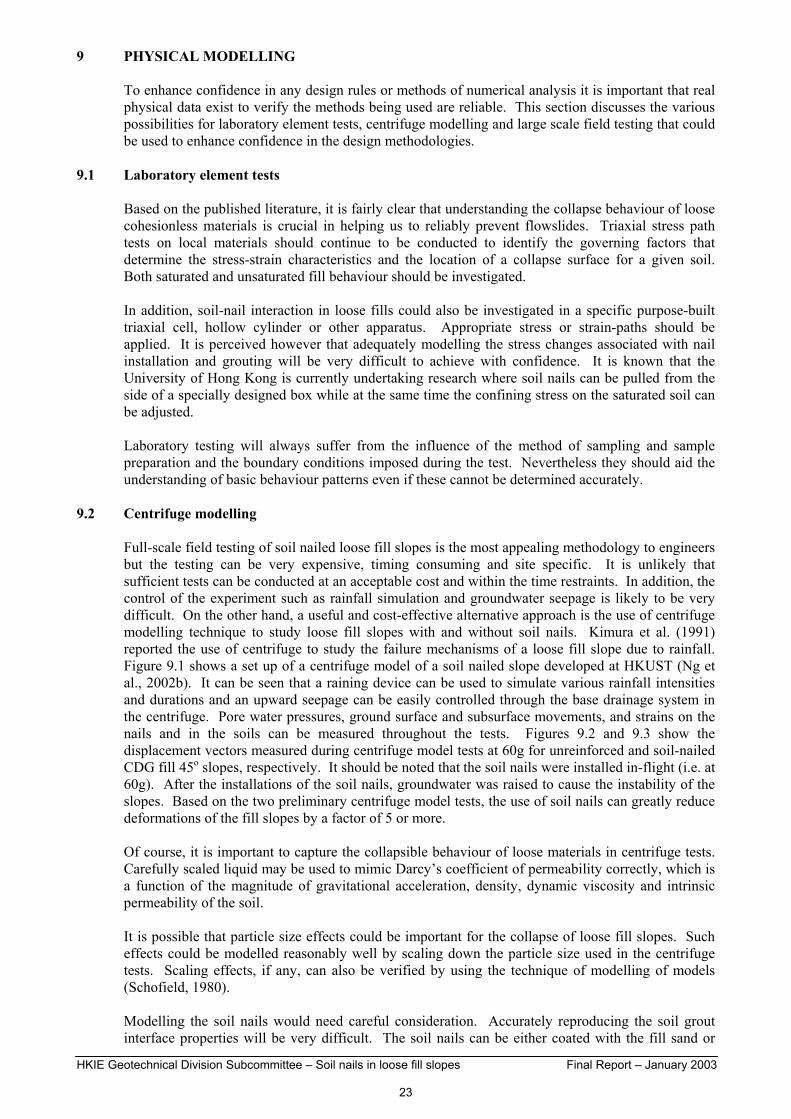
HKIE Geotechnical Division Subcommittee – Soil nails in loose fill slopes Final Report – January 2003
23
9 PHYSICAL MODELLING To enhance confidence in any design rules or methods of numerical analysis it is important that real physical data exist to verify the methods being used are reliable. This section discusses the various possibilities for laboratory element tests, centrifuge modelling and large scale field testing that could be used to enhance confidence in the design methodologies.
9.1 Laboratory element tests Based on the published literature, it is fairly clear that understanding the collapse behaviour of loose cohesionless materials is crucial in helping us to reliably prevent flowslides. Triaxial stress path tests on local materials should continue to be conducted to identify the governing factors that determine the stress-strain characteristics and the location of a collapse surface for a given soil. Both saturated and unsaturated fill behaviour should be investigated. In addition, soil-nail interaction in loose fills could also be investigated in a specific purpose-built triaxial cell, hollow cylinder or other apparatus. Appropriate stress or strain-paths should be applied. It is perceived however that adequately modelling the stress changes associated with nail installation and grouting will be very difficult to achieve with confidence. It is known that the University of Hong Kong is currently undertaking research where soil nails can be pulled from the side of a specially designed box while at the same time the confining stress on the saturated soil can be adjusted. Laboratory testing will always suffer from the influence of the method of sampling and sample preparation and the boundary conditions imposed during the test. Nevertheless they should aid the understanding of basic behaviour patterns even if these cannot be determined accurately.
9.2 Centrifuge modelling Full-scale field testing of soil nailed loose fill slopes is the most appealing methodology to engineers but the testing can be very expensive, timing consuming and site specific. It is unlikely that sufficient tests can be conducted at an acceptable cost and within the time restraints. In addition, the control of the experiment such as rainfall simulation and groundwater seepage is likely to be very difficult. On the other hand, a useful and cost-effective alternative approach is the use of centrifuge modelling technique to study loose fill slopes with and without soil nails. Kimura et al. (1991) reported the use of centrifuge to study the failure mechanisms of a loose fill slope due to rainfall. Figure 9.1 shows a set up of a centrifuge model of a soil nailed slope developed at HKUST (Ng et al., 2002b). It can be seen that a raining device can be used to simulate various rainfall intensities and durations and an upward seepage can be easily controlled through the base drainage system in the centrifuge. Pore water pressures, ground surface and subsurface movements, and strains on the nails and in the soils can be measured throughout the tests. Figures 9.2 and 9.3 show the displacement vectors measured during centrifuge model tests at 60g for unreinforced and soil-nailed CDG fill 45o slopes, respectively. It should be noted that the soil nails were installed in-flight (i.e. at 60g). After the installations of the soil nails, groundwater was raised to cause the instability of the slopes. Based on the two preliminary centrifuge model tests, the use of soil nails can greatly reduce deformations of the fill slopes by a factor of 5 or more. Of course, it is important to capture the collapsible behaviour of loose materials in centrifuge tests. Carefully scaled liquid may be used to mimic Darcy’s coefficient of permeability correctly, which is a function of the magnitude of gravitational acceleration, density, dynamic viscosity and intrinsic permeability of the soil. It is possible that particle size effects could be important for the collapse of loose fill slopes. Such effects could be modelled reasonably well by scaling down the particle size used in the centrifuge tests. Scaling effects, if any, can also be verified by using the technique of modelling of models (Schofield, 1980). Modelling the soil nails would need careful consideration. Accurately reproducing the soil grout interface properties will be very difficult. The soil nails can be either coated with the fill sand or

HKIE Geotechnical Division Subcommittee – Soil nails in loose fill slopes Final Report – January 2003
24
grouted with a paste mixture of calcium aluminate, sand and water. Installing the soil nails in-flight has been achieved by pushing them in. This overcomes the obvious difficulty associated with having the nails in place prior to flying the centrifuge model that will result in the nails being stressed before failure is initiated by water inflow. An alternative method may be to use visco-elastic plastic nails that will be effectively unstressed under sustained load but react stiffly if a sudden load is imposed on them. It must be emphasised that, as there are considerable challenges in accurately modelling this complex three dimensional problem a limited number of large scale field tests should also be carried out to verify the key findings from the centrifuge tests.
9.3 Large scale field testing As a minimum detailed instrumentation should be planned and conducted on some loose fill slopes that are strengthened by soil nails. Hopefully the field data would lead to a much better understanding of the effectiveness of soil nails when the slope is subjected to extreme weather events. It is likely, however, that the only way to confidently determine the behaviour of nails in loose fill slopes, such that the most economic design can be determined is by means of large-scale tests where failure is deliberately induced. As for the centrifuge tests, experiments with and without nails would be needed. Only a limited range of conditions could realistically be attempted and numerical modelling and possibly centrifuge testing should be used to extrapolate and interpolate to other conditions. An important feature revealed by the calculations is the amount of shaft friction that can be mobilised along the soil nail when the fill is wet. This should be investigated using suitable field experiments. The report by Simpson (Ove Arup and Partners, 1996) discusses how such a test could be attempted.

HKIE Geotechnical Division Subcommittee – Soil nails in loose fill slopes Final Report – January 2003
25
10 DESIGN RECOMMENDATIONS From the study discussed in this report, it is concluded that soil nails is a feasible option for upgrading loose fill slopes, even allowing for the potential collapse behaviour of such soils. It is considered that the principles used in the calculations presented in Chapter 7 are reasonable and conservative as interim recommendations. For design purposes, a slope comprising loose fill having a relative compaction of at least 75%, this method reduces to the following steps: 1. The geometry should be analysed in the conventional way using limit equilibrium methods. In
the first instance the geometry should be checked to assess whether the conventional factor of safety specified in the ‘Geotechnical Manual for Slopes’ is achieved against the possibility of undrained collapse behaviour. Undrained triaxial compression tests on saturated remoulded samples of loose fill show that the lower bound shear strength before the onset of undrained behaviour can be represented by a φ’ value equal to 260 (see Figure 5.12). Material specific testing may show a higher result however. In the stability calculations positive pore water pressures should be used if a perched water table or phreatic surface is assessed to be a reasonable possibility. Otherwise zero pore water pressure would be assumed. This first step in the design process will generally mean that upgrading works will not be required on a slope that is no steeper than about 200 if the slope is not subject to positive pore water pressures.
2. If remedial measures are required, conventional slope stability calculations with a minimum
factor of safety of 1.1 should be used to determine the required axial nail resistance. In these calculations it will be conservative to represent the strength of the fill by its large strain steady state undrained shear strength. If site-specific laboratory testing is not carried out a conservative value of steady state undrained shear strength equal to 0.2 times the mean effective stress at the onset of undrained behaviour is recommended. This can be conservatively assumed to be the mean effective stress that would exist in the slope assuming no suction is present. If a perched water table or phreatic surface is assessed to be a reasonable possibility then positive pore water pressures should be used when determining the mean effective stresses. For a slope with no positive pore water pressure this results in an undrained shear strength to vertical stress ratio of about 0.13. Laboratory testing can be used to determine the undrained shear strengths and it is expected that the tests will show that undrained shear strengths of at least twice those implied by this ratio will be appropriate in many cases. The soil nails should be assumed to be at their ultimate tensile capacity, as defined by BS8110, under these conditions. Allowance for corrosion should made as usual.
If laboratory testing is to be carried out to derive the steady state undrained shear strength of the fill, it is recommended that the procedures given in Section 5.1 of this report, i.e. isotropically consolidated undrained triaxial compression tests on back-pressure saturated specimens of remoulded fill taken from representative bulk samples, be used. It is important that the testing schedule includes a sufficient number of tests to provide results representative of the range of dry densities of the fill in the slope and of the stress levels insitu. Bulk samples should be collected from different locations across the slope for testing. The range of relative compaction of the remoulded fill specimens should match the site conditions and the confining stresses to be applied during the consolidation stage should be as close to those corresponding to the shallow zone of fill in the slope that may be susceptible to liquefaction. The tests should cover a range of confining pressures starting from 25kPa. The available test results show that the lower confining pressures tend to give the lower cSS/p’peak values. Also, it has been observed that the dry density of the specimens would change during the saturation and consolidation stages. Therefore, the dry density prior to shearing should be used for determining the corresponding relative compaction of the test specimen, rather than the initial dry density.
The general guidance given in Sections 5.2 and 5.3 of Geoguide 1 (GEO, 1993) on the determination of selected values of geotechnical parameters for design is relevant. It is recommended that the selected values of steady state shear strength be obtained from a careful evaluation of the test results. Account should be taken of the adequacy and consistency of the test data, the appropriateness of the test conditions in relation to the likely field conditions, and the variability of the fill. The representativeness of the test specimens with respect to the fill mass in the slope that may be susceptible to liquefaction failure (in particular, the range of dry densities and

HKIE Geotechnical Division Subcommittee – Soil nails in loose fill slopes Final Report – January 2003
26
relative compaction values of the fill and the stress levels) should also be considered. Reasonably conservative selected values of shear strength should be adopted. In this respect, sensitivity checks of design parameters should be carried out. It is recommended that the soil nails should be placed at a spacing of no greater than 2m horizontal and 1.5m vertical spacing. A surface grillage connecting the nail heads or some other structural surfacing will be required to ensure that all of the soil is effectively restrained against downslope movement. The grillage should extend about 0.5m below the fill surface to ensure good contact with the fill and it needs to be designed to be able to spread the predicted nail tension forces across the slope surface. Calculations are presented in Chapter 7 to show how the required nail force can be assessed and it is demonstrated that, in many cases, the nail tensile capacity will need to progressively increase down the slope. The width of the beams forming the grillage should be such that the loose fill material cannot squeeze out between the grillage beams. The grillage beams must be able to span between the nails and to have sufficient structural capacity to ensure the grillage behaves in a monolithic manner. Again ultimate strengths as defined in BS8110 are recommended to be used for this design. Established detailing practice should be adopted (e.g. Civil Engineering Department, Standard Drawings). The surface cover or grillage needs to be detailed such that it can be installed around existing mature and proposed vegetation. It is also vital that it prevents, or at least severely limits the ingress of surface water and also allows excess pore water pressure to drain away. Therefore frequent weepholes together with prescriptive raking drains should be used which will also prevent any possible build-up of water pressure at depth. GEO Report No. 56 (Wong & Pang, 1996) shows typical surface protection and drainage details to achieve this aim. In addition, attention needs to be given to good detailing to avoid erosion from concentrated surface water flow. The nails should extend sufficiently below the assessed failure surface to ensure the required ultimate tensile capacity can be achieved. In general it would be prudent to socket the nail into natural material to obtain sufficient anchorage instead of having nails embedded entirely within fill that could be highly heterogeneous. It must be realised that installing soil nails in loose fill can be difficult and will require careful monitoring. The grout take may be large and some ground movement during installation will be inevitable. Sensitive structures should be identified and instrumented prior to the soil nail installation and monitored during the nail construction. Mitigation measures should be taken when necessary to prevent damage to these structures. Most of the work presented in this report has largely been based on loose fill comprising completely decomposed granite. Limited testing on one source of fill of volcanic origin indicates its liquefaction potential is less than that of the granite-derived material. It is recommended, at this stage, that similar guidelines be used for both types of materials.

HKIE Geotechnical Division Subcommittee – Soil nails in loose fill slopes Final Report – January 2003
27
REFERENCES Balkema, (1996). Earth Reinforcement - Proceedings of the International Symposium on Earth Reinforcement, Ochiai, Yasufuku and Omine Editors. Binnie and Partners (Hong Kong), (1981). Detailed Inspection Report for Sau Mau Ping Estate - Slopes 11NE-D/F5 and F6, 46p. Cardose, A.S. & Carreto, A.P. (1989). Performance and analysis of a nailed excavation. Proc. of the 12th Int. Conf. on Soil Mechanics and Foundation Engineering, Vol. 2, pp. 1233-1236. Charles, J.A. & Watts, K.S. (1996). The assessment of the collapse potential of fills and its significance for building on fill. Proc. of the Inst. Civil Eng. Geotechnical Engineering, Vol. 119, pp. 15-28. Cheuk, C.Y., Ng, C.W.W. & Sun, W. H. (2001). Numerical analysis of soil nail in loose fill slopes. Proc. of the 14th South East Asian Geotechnical Conf., Hong Kong. Vol. 1, 725-730. Chiu, C.F., Ng, C.W.W. & Shen, C.K. (1998). Collapse behaviour of loosely compacted virgin and non-virgin fills in Hong Kong. Proc. of the 2nd. Int. Conf. on Unsaturated Soils, Beijing. Vol.1, 25-30. Dawson, R.F., Morgenstern, N.R. & Gu, W.H. (1992). Instability Mechanisms Initiating Flow Failures in Mountainous Mine Waste Dumps, University of Alberta, 80p. DiPrisco, C., Matiotti, R. & Nova, R. (1995). Theoretical investigation of the undrained stability of shallow submerged slopes. Geotechnique, Vol. 45, pp. 479-496. Drumm, E.C., Tant, C.R., Mauldon, M. & Berry, R.M. (1996). Instrumentation of a nailed mine-waste slope. Proc. of the International Symposium on Earth Reinforcement, Ochiai, Yasufuku and Omine Editors, Balkema, pp. 741-752. Drumm, E.C., Mauldon, M. & Tant, C.R. (1998). Ground Improvement 2, pp. 147-156. Ehrlich, M., Almeida, M.S.S. & Lima, A.M. (1996). Parametric numerical analyses of soil nailing system. Proc. of the Int. Sym. on Earth Reinforcement, Japan, Vol. 1, pp. 747-752. Fredlund, D.G. & Rahardjo, H. (1993). Soil Mechanics for Unsaturated Soils. John Wiley and Sons. Gan, J.K.M. & Fredlund, D.G. (1996). Shear strength characteristics of two saprolitic soils. Canadian Geotechnical Journal 33, 595-609. GEO Circular No. 9 (1998). Geotechnical Manual for Slopes - Guidance for Interpretation. Geotechnical Engineering office, Hong Kong. GEO (1993). Guide to Retaining Wall Design (Geoguide 1). Geotechnical Engineering Office, Hong Kong. Gu, W.H. (1992). Liquefaction and Post Earthquake Deformation Analysis. PhD Thesis, University of Alberta, Canada. Gu, W.H., Morgenstern, N.R. & Robertson, P.K. (1993). Progressive failure of lower San Fernando Dam. Journal of Geotechnical Engineering, ASCE, Vol. 119, No. 2, pp. 333-349. Hicks, M.A. & Wong, S.W. (1988). Static liquefaction of loose slopes. Proc. of the Conf. on Numerical Methods in Geomechanics, Innsbruck, edited by Swoboda, pp. 1361-1367. Heymann, G., Rohde, A.W., Schwartz, K. & Friedlaender, E. (1992). Soil nail pull out resistance in residual soils. Proc. Earth Reinforcement Practice, Ochai, Hayashi & Otani (eds), Balkema, pp. 497-492. Hong Kong Government (1977). Report on the Slope Failures at Sau Mau Ping, August 1976. Hong Kong Government Printer, 105p. Plus 8 drgs.

HKIE Geotechnical Division Subcommittee – Soil nails in loose fill slopes Final Report – January 2003
28
Ingold, T.S. & Myles, B. (1996). Ballistic soil nailing. Proc. of the International Symposium on Earth Reinforcement, Ochiai, Yasufuku and Omine Editors, Balkema, pp. 765-770. Kenny, M.J. & Kawai, Y. (1996). The effect of bending stiffness of soil nails on wall deformation. Proc. of the Int. Sym. on Earth Reinforcement, Japan, Vol. 1, pp. 771-774. Kimura, T., Takemura, J., Suemasa, N. & Hiro-oka, A. (1991). Failure of fills due to rainfall. Centrifuge 91, pp. 509-516. Law, K.T., Shen, J.M. & Lee, C.F. (1997). Strength of a loose remoulded granitic soil. Proc. of the 16th. HKIE Geotechnical Division Annual Seminar, “Slope engineering in Hong Kong”, Balkema, pp 169-176, May 1997. Law, K.T., Lee, C.F., Luan, M.T. & Zhai, Y. (1997). Laboratory Investigation of Fundamental Behaviour of Loose Fill under Shear. Department of Civil and Structural Engineering, The University of Hong Kong. Lee, H.L. (1997). The Behaviour of a Loosely Compacted Soil in Hong Kong. HKUST, Final-year project report. Martin, J. (1997). The design and installation of soil nail, slope stabilisation schemes using ‘Snail’. Proc. of the 3rd. Int. Conf. on Ground Improvement Geosystems, Thomas Telford, pp. 399-406. Molenkamp, F. (1981). Elasto-plastic double hardening model MONOT. Delft Soil Mechanics Laboratory, Report No. CO-218595. Morgenstern, N.R. (1978). Mobile soil and rock flows. Geotechnical Engineering, Vol. 9, pp. 123-141. Ng, C.W.W., Chiu, C.F. & Shen, C.K. (1998). Effects of the wetting history on the volumetric deformations of an unsaturated loose fill. Collapse of a loose residual soil. Proc. of the 13th. Southeast Asian Geotechnical Conf., Taiwan. Vol.1, 141-146. Ng, C.W.W. & Chiu, C.F. (2000). Undrained behaviour of loosely compacted fills and its implications on slope stabilisation measures. Proc. 8th Int. Sym. on Landslides, Cardiff, June, Vol. 3, 1087-1092. Ng, C.W.W. & Chiu, C.F. (2001). Behaviour of a loosely compacted unsaturated volcanic soil. Journal of Geotechnical and Geo-environmental Engineering, ASCE, Vol. 127, No.12, 1027-1036. Ng, C.W.W & Chiu, C.F. (2002). Laboratory study of loose saturated and unsaturated decomposed granitic soil. Journal of Geotechnical and Geo-environmental Engineering, ASCE, In press. Ng, C.W.W., Fung, W.T., Cheuk, C.Y.& Zhang, L.M. (2002a). Influence of stress ratio and stress path on behaviour of loose decomposed granite. Journal of Geotechnical and Geo-environmental Engineering, ASCE, Provisionally accepted. Ng, C.W.W. & Lee, G.T.K. (2002). A three-dimensional parametric study of the use of soil nails for stabilising tunnel faces. Computers and Geotechnics. Vol. 29, No. 8, 673-697. Ng, C.W.W. Zhang, M. & Shi, X.G. (2002b). An investigation into the use of soil nails in loose fill slopes. Invited keynote paper (In Chinese). Proc. of the First Chinese Symposium on Geoenvironment and Geosynthetics, 17-19 Nov., Hangzhou, Zhejiang, China, 61-80. Ove Arup and Partners, (1996). The use of soil nails to upgrade loose fill slopes. Ove Arup and Partners, London, Report for GEO as part of their remedial stabilisation of Hong Kong fill slopes.

HKIE Geotechnical Division Subcommittee – Soil nails in loose fill slopes Final Report – January 2003
29
Richards, B.G. (1992). Modelling interactive load-deformation and flow processes in soils, including unsaturated and swelling soils. (John Jaeger Memorial Address). Proc. of the 6th Australia - New Zealand Conference on Geomechanics, Christchurch, New Zealand, pp. 18-37. Riemer, M.F. & Seed, R.B. (1997). Factors affecting apparent position of steady state line. Journal of Geotechnical Engineering, ASCE, Vol. 123, No. 3, pp. 281-288. Sasitharan, S., Robertson, P.K., Sego, D.C. & Morgenstern, N.R. (1993). Collapse behaviour of sand. Canadian Geotechnical Journal, Vol. 30, pp. 569-577. Sasitharan, S., Robertson, P.K., Sego, D.C. & Morgenstern, N.R. (1994). State-boundary surface for very loose sand and its practical implications. Canadian Geotechnical Journal, Vol. 31, pp. 321-334. Schofield, A.N. (1980). Cambridge University Geotechnical Centrifuge Operations. Geotechnique, Vol. 30, No. 2, pp. 227-268. Shiu, Y.K., Yung, P.C.Y. & Wong, C.K. (1997). Design, construction and performance of a soil nailed excavation in Hong Kong. Proc. of the 14th Int. Conf. on Soil Mech. and Found. Eng., Hamburg, Germany. Skopek, P., Morgenstern, N.R., Robertson, P.K. & Sego, D.C. (1994). Collapse of dry sand. Canadian Geotechnical Journal, Vol. 31, pp. 1008-1014. Sladen, J.A., D’Hollander, R.D. & Krahn, J. (1985). The liquefaction of sands, a collapse surface approach. Canadian Geotechnical Journal, Vol. 22, pp. 564-578. Sun, H.W. (1998). Review of fill slope failures in Hong Kong, GEO Special Project Report SPR 4/98, Geotechnical Engineering Office, Civil Engineering Dept., Hong Kong. Tadepalli, R. & Fredlund, D.G. (1991). The collapse behaviour of a compacted soil during inundation. Canadian Geotechnical Journal, Vol. 28, pp. 477-488. Tadepalli, R., Fredlund, D.G. & Rahardjo, H. (1992). Soil collapse and matrix suction change. Proc. of the 7th Int. Conf. on Expansive Soils, Dallas, Texas. Thomas Telford (1997). Ground Improvement Geosystems Densification and Reinforcement - Proceedings of the Third International Conference on Ground Improvement Geosystems. Thompson, S.R. & Miller, I.R. (1990). Design, construction and performance of a soil nailed wall in Seattle, Washington. Design and Performance of Earth Retaining Structures, ASCE Geotechnical Special Publication No. 25, pp. 629-643. Unterreiner, P., Benhamida, B. & Schlosser, F. (1997). Finite element modelling of the construction of a full-scale experimental soil-nailed wall. French National Research Project CLOITERRE. Ground Improvement, Vol. 1, pp. 1-8. Wheeler, S.J. & Sivakumar, V. (1995). An elasto-plastic state framework for unsaturated soil. Geotechnique, Vol. 45, No. 1, pp. 35-53. Wong, H.N. (1992). Report on the investigation of the 8 May 1992 Kennedy Road landslide. GEO Advisory Report ADR 27/92, Geotechnical Engineering Office, Civil Engineering Department, Hong Kong. Wong, H.N. & Pang, L.S. (1996). Application of prescriptive measures to soil cut slopes. GEO Report No. 56, Geotechnical Engineering Office, Civil Engineering Dept., Hong Kong.

HKIE Geotechnical Division Subcommittee – Soil nails in loose fill slopes Final Report – January 2003
30
APPENDIX
Changes in recommendations from the November 1998 Draft Report The differences in design recommendations between the Draft Report published in November 1998 and this Final Report are relatively minor in that the basic design philosophy is unchanged. The two-step procedure is maintained. The first step of checking has become a little more cautious in that the ‘Geotechnical Manual for Slopes’ is referred to when identifying the appropriate factor of safety on soil strength associated with the onset of undrained behaviour. Previously a minimum factor of safety of 1.2 was suggested whereas a minimum factor of 1.4 will now be required for Consequence-to-life Category 1 slopes. The second step has also become more cautious. The Draft Report recommended that sufficient nails be installed to sustain the slope to maintain a minimum factor of safety of one for a soil having a steady state shear strength defined by a cSS/p’peak ratio of 0.4. The additional tests reported here suggest that this may not be conservative and a cSS/p’peak ratio of 0.2 needs to be allowed for unless site-specific laboratory testing can demonstrate a higher value. In addition a minimum factor of safety of 1.1 is now recommended. The Draft Report presented results for an infinite slope to illustrate the likely density and diameter of soil nails. That analysis assumed that only the loose fill on the failure surface is in the liquefied (steady state strength) condition. In this Final Report it is assumed that the entire loose fill mass is in the liquefied condition. This more conservative assumption necessitates the use of a surface grillage in most cases and guidance is given in this report as to how to derive the normal stresses this grillage may be required to resist The scope of application of the report has also changed somewhat. The Draft Report only discussed fill of CDG origin but the limited data on one source of CDV fill material presented in this report shows that this material is very likely to have less susceptibility to static liquefaction than the granite-derived fills tested and therefore the recommendations can be applied to fill of CDV origin as well. The Draft Report also suggested that the slope height should be limited to 10m for slopes affecting Consequence-to-life Category 1 facilities (see GEO Circular No. 9, 1998). Given the more cautious approach suggested in this Final Report this limitation has been removed.

HKIE Geotechnical Division Subcommittee – Soil nails in loose fill slopes Final Report – January 2003
31
LIST OF TABLES Table Title No. 2.1 Case histories of liquefaction of loose fill in Hong Kong 4.1 Examples of Soil Nailing in “loose” fill 5.1 Location and some characteristics of CDG fill 5.2 λ values for some sands (data from Sasitharan et al. 1994) 5.3 Summary of index properties

HKIE Geotechnical Division Subcommittee – Soil nails in loose fill slopes Final Report – January 2003
32
Table 2.1 Case histories of liquefaction of loose fill in Hong Kong
Location Slope Height (m)
Slope Angle(degrees)
Volume (m3)
Angle of reach(degrees)
Kwun Tong - 1964 ? ? 10000 17
Victoria Height - 1966 ? ? 4000 19
Sau Mau Ping - 1972 40 35 6000 16
Sau Mau Ping - 1976 32 35 4000 <23
Princess Margaret Road - 1989 11 40 200 26
Kowloon Wah Yan College - 1989 12 40 50 24
Hong Kong Wah Yan College - 1992 (Kennedy Road)
15 40 500 <28
Source: GEO

HKIE Geotechnical Division Subcommittee – Soil nails in loose fill slopes Final Report – January 2003 P. 33
Table 4.1: Examples of Soil Nailing in “loose” fill
Country Job Title Height (m)
Slope angle (deg)
Material Nail length (m)
Nail spacing h(m)*v(m)
Comments Reference
UK Broughton Heath
10 32 poorly compacted fill 10 to 14 2.5 x 2 Veneer pinned to underlying boulder clay – Permanent works
Martin (1997)
UK Gateshead 10 90 poor embankment fill 8 1 x 1 steel heads, geosynthetic face, significant movement - Temporary works
Martin (1997)
USA Tennessee 12 45 mine spoil - shale, sandstone, coal
3 to 6 1.5 x 1.5 1.8 x 1.8
Instrumented trial sections
Drumm et al (1996)
HK DSB 25 60 gravelly, clayey sand cobbles and boulders
10 2 x 2 Temporary cut slope Gammon
UK Stoke 5 45 shraff (ash and other waste from pottery)
Temporary cut slope SW UK
UK Clay fill 5 Temporary cut slope ballistic soil nails
Ingold and Myles (1996)

HKIE Geotechnical Division Subcommittee – Soil nails in loose fill slopes Final Report – January 2003 34
Table 5.1 Location and some characteristics of CDG fill
Location Fines content (%)
Clay content (%)
Plasticity Index (%)
φ’ (degrees)
λ
King’s Park 38 --- --- 36 0.084
Chi Lin Ching Yuen 43 33 53 38 0.098
Valley Road Estate 21 8 12 40 0.078
Diamond Hill 18 10 27 40 0.108
Ho Man Tin 36 17 --- --- 0.048
Stubbs Road 26 12 --- --- 0.048
Lai Ping Road 67 38 40 --- 0.130
Shau Kei Wan 23 14 29 39 0.098
Beacon Hill 22 7 18 39 0.050
Table 5.2: λ values for some sands (data from Sasitharan et al. 1994)
Mineralogy λ Comments
Quartz, rounded to subrounded 0.018
73% quartz, 22% feldspar, rounded to subrounded
0.013 pSS’< 1000 kPa
75% quartz, 25% feldspar, rounded to subrounded
0.004 pSS’< 100 kPa
75% quartz, 25% feldspar, rounded to subrounded
0.028 100 < pSS’< 1000 kPa
Quartz, angular 0.022 pSS’< 200 kPa
95% quartz 0.017
95% quartz 0.014 Note: pSS’ = mean effective principal stress at steady state

HKIE Geotechnical Division Subcommittee – Soil nails in loose fill slopes Final Report – January 2003 35
Table 5.3 Summary of index properties
Property Indian Head silt
CDG colluvium (Hong Kong)
Grain size distribution
Sand 62% 25%
Silt 32% 65%
Clay 6% 10%
D10 0.0034mm 0.0014mm
D30 0.025mm 0.006mm
D60 0.09mm 0.02mm
Coeff. of uniformity (D60 /D10) 26.4 14.3
Liquid limit 22.2% 48%
Plastic limit 16.6% 35%
Plasticity Index 5.6% 13%
Specific Gravity 2.68 2.66
Max. dry density 1870 kg/m3 1540 kg/m3
Optimum Moisture Content 13.4% 21%

HKIE Geotechnical Division Subcommittee – Soil nails in loose fill slopes Final Report – January 2003 36
LIST OF FIGURES Figure Title No. 1.1 Behaviour of soil element on failure surface 1.2 Shear capacity versus demand for a loose soil 1.3 Forces acting on potential sliding zone for a nailed slope 1.4 Downslope capacity versus demand for an adequately nailed slope 2.1 Data on debris mobility for different mechanisms and scale of fill slope failures in Hong Kong
(Sun 1998) 2.2 Typical section of 1976 Sau Mau Ping failure (HK Government 1977)
2.3 Crest line of 1976 Sau Mau Ping landslide (HK Government 1977) 2.4 Cross section through reconstructed slope at Sau Mau Ping (Binnie Hong Kong 1981) 2.5 Location of springs after slope reinstatement, Sau Mau Ping (Binnie Hong Kong 1981) 2.6 Section of the 8 May 1992 landslide at Kennedy Road (Wong 1992) 3.1 Response of saturated Ottawa Sand during constant deviator stress (q=125kPa) drained test
(Sasitharan et al. 1993) 3.2 Collapse behaviour of CDG subjected to increasing pore water pressure under constant deviator
stress (Ng et al. 2002a) 3.3 Undrained triaxial tests on specimens pre-sheared previously under drained conditions (DiPrisco et al. 1995)
3.4 Effect of initial stress ratio on ductility of anisotropically consolidated undrained test specimens
(Ng et al. 2002a) 3.5 Stress path and contraction during constant - q tests (Skopek et al. 1994) 3.6 Figures reproduced from Wheeler & Sivakumar (1995) 3.7 Loading and unloading constitutive surfaces for a stable-structured unsaturated soil (Fredlund &
Rahardjo 1993) 3.8 Loading and unloading constitutive surfaces for a meta-stable-structured unsaturated soil
(Tadepalli et al. 1992) 3.9 Relationships between (a) axial strain and suction, (b) volumetric strain and suction for wetting
tests at constant deviator stress conducted on unsaturated specimens of decomposed granitic soil (Ng & Chiu, 2002)
5.1 Typical effective stress paths of isotropically consolidated undrained tests on loose CDV
specimens (Ng & Chiu, 2002)

HKIE Geotechnical Division Subcommittee – Soil nails in loose fill slopes Final Report – January 2003 37
LIST OF FIGURES (Cont.) Figure Title No. 5.2 Results of undrained triaxial tests on saturated samples of CDG fill at King’s Park (Law et al. 1997)
5.3 Results of consolidated undrained triaxial tests (Valley Estate) 5.4 Results of consolidated undrained triaxial tests (Chi Lin Ching Yuen) 5.5 Results of consolidated undrained triaxial tests (Diamond Hill) 5.6 Deviator stress plotted against mean normal stress at steady state 5.7 Void ratio plotted against mean effective stress at steady state 5.8 Steady state strength plotted against void ratio 5.9 Steady state strength plotted against Relative Compaction 5.10 Steady state strength plotted against mean effective stress at peak strength 5.11 Steady state strength as a ratio of mean effective stress at peak strength plotted against Relative
Compaction 5.12 Deviator stress plotted against mean normal stress at peak strength 5.13 Void Ratio – pressure curves for different test types on different specimen types 5.14 Critical state of unsaturated specimens of decomposed granitic soil in the plane of (a) specific
volume and net mean stress, and (b) deviator stress and net mean stress (Ng & Chiu, 2002)
5.15 Relationship of soil suction (s) and apparent cohesion µ(s) (Ng & Chiu, 2001) 5.16 Relationship between matrix suction, collapse settlement and time (Lee 1997) 5.17 Collapse potential versus moisture content at different constant relative compaction (Lee 1997) 5.18 Relationship between collapse potential and relative compaction (Ng et al. 1998) 5.19 Test results on Indian Head silt (Tadepalli & Fredlund 1991) 6.1 Information on Pre-1977 fill slopes registered in the Hong Kong Government’s slope catalogue 6.2 Profile of void ratio of selected pre-1977 fill slopes in Hong Kong 6.3 Profile of relative compaction of selected pre-1977 fill slopes in Hong Kong 6.4 Particle size distribution for pre-1977 fill slopes in Hong Kong 6.5 Profile of Atterberg Limits for pre-1977 fill slopes in Hong Kong 6.6 Profile of degree of saturation for selected pre-1977 fill slopes in Hong Kong

HKIE Geotechnical Division Subcommittee – Soil nails in loose fill slopes Final Report – January 2003 38
LIST OF FIGURES (Cont.)
Figure Title No. 7.1 Sliding of soil under nail head beams 7.2 Layout of surface grillage 7.3 Normal stresses predicted by FLAC for a 10 m high 1 in 1.5 slope with 3 m depth of failing loose
fill 7.4 Example of circular slip surface limit equilibrium analysis 8.1 Molenkamp’s yield surfaces in octahedral plane for triaxial compression (Hicks & Wong 1988)
8.2 Simplified Undrained Model for Liquefiable Soils (Gu et al. 1993)
8.3 GEO’s liquefaction model for loose fill
8.4 Result of FLAC analysis of nailed loose fill slope – displacement vectors at failure or at prototype
time 60 seconds (Cheuk et al. 2001) 8.5 Result of FLAC analysis of nailed loose fill slope – shear strain distribution at failure or prototype
time 60 seconds (Cheuk et al. 2001) 9.1 Centrifuge model slope inside a model container (Ng et al. 2002b) 9.2 Displacement Vectors in Unreinforced CDG Fill Slope (Ng et al. 2002b) 9.3 Displacement Vectors in Soil-nailed CDG Fill Slope (Ng et al. 2002b)

Figure 1.1 – Behaviour of Soil Element on Failure Surface

Figure 1.2 – Shear Capacity versus Demand for a Loose Soil
Soil capacity
Applied stress
Shearstress
Shear displacement
B

Figure 1.3 – Forces Acting on Potential Sliding Zone for a Nailed Slope
W
N
D RS
RN
Soil Nail
Potential sliding zone

Figure 1.4 – Downslope Capacity Versus Demand For an Adequately Nailed Slope
Soil Resistance RS
Total ResistanceRS + RN
Driving Force D
Nail Resistance RN
Downslope Displacement
DownslopeForces

Figure 2.1 – Data on Debris Mobility for Different Mechanisms and Scale of Fill Slope Failures in Hong Kong (Sun, 1998)

Figure 2.1 – Data on Debris Mobility for Different Mechanisms and Scale of Fill Slope Failures in Hong Kong (Sun, 1998)

Figure 2.2 – Typical Section on 1976 Sau Mau Ping Failure
Note: Figure Extracted from Hong Kong Government (1977)

Figure 2.3 – Crest line of the 1976 Sau Mau Ping Landslide (HK Government, 1977)

Figure 2.4 – Cross-section through Reconstructed Slope at Sau Mau Ping

Figure 2.5 – Location of Springs after Slope Reinstatement at Sau Mau Ping

Figure 2.6 – Section of athe 8 May 1992 Landslide at Kennedy Road (Wong, 1992)

Figure 3.1 – Response of saturated Ottawa Sand during constant deviator stress (q=125kPa) drained test (Sasitharan et al. 1993)

Figure 3.2 - Collapse behaviour of CDG subjected to increasing pore water pressure under constant deviator stress (Ng et al. 2002a)
0
20
40
60
80
100
120
0 20 40 60 80 100 120 140
Mean effective stress, p' (kPa)
Dev
iato
r st
ress
, q (
kPa)
q/p’ = 1.12 q/p’ = 1.58
stress state at onset of large axial strain ( at collapse) q/p’ line showing collapse
surface for conventional normally consolidated undrained triaxial test

Figure 3.3 – Undrained Triaxial Tests on Specimens Pre-sheared Previously under Drained Conditions (Di Prisco et al. 1995)
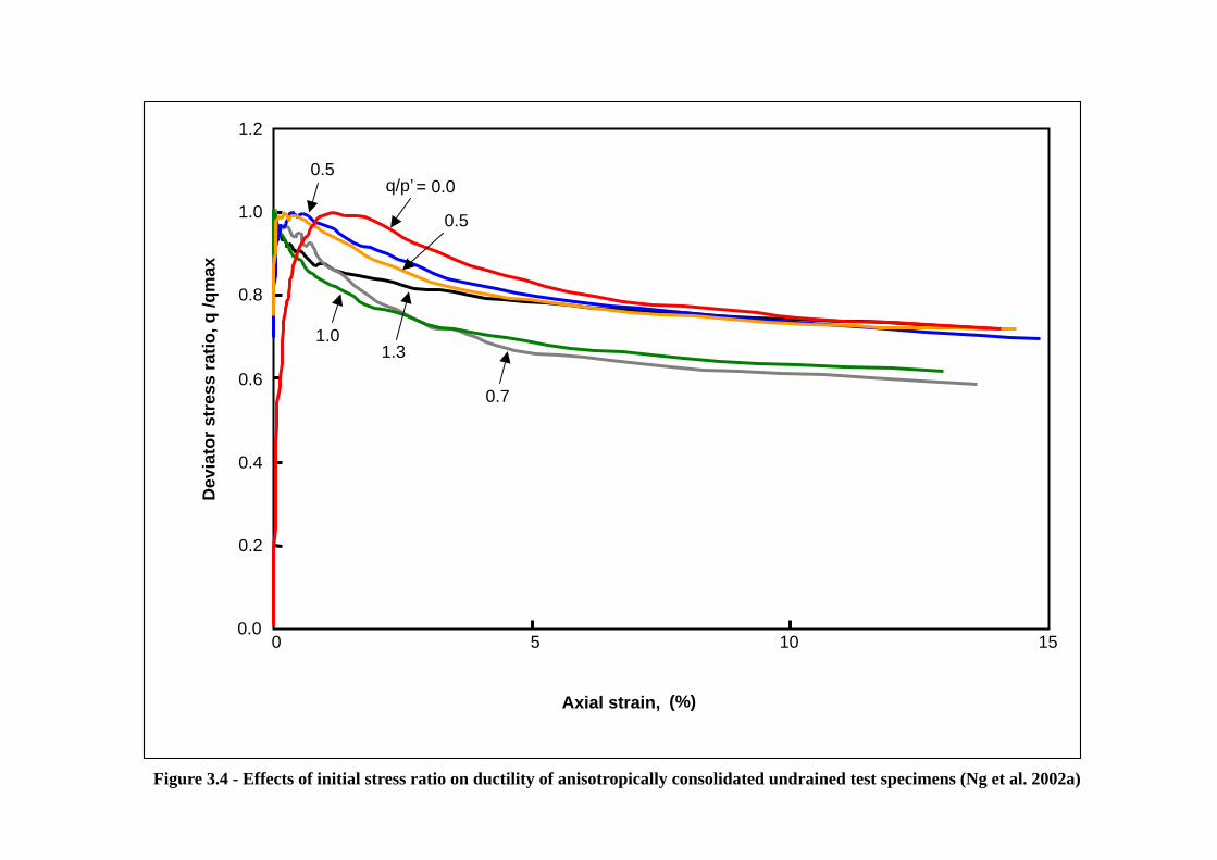
Figure 3.4 - Effects of initial stress ratio on ductility of anisotropically consolidated undrained test specimens (Ng et al. 2002a)
0.0
0.2
0.4
0.6
0.8
1.0
1.2
0 5 10 15
Axial strain, (%)
Dev
iato
r st
ress
rat
io, q
/qm
ax
q/p’ = 0.0 0.5
0.5
1.0 1.3
0.7

Figure 3.5 – Stress Path and Contraction During Constant-q (Skopek et al, 1994)

Figure 3.6 – Figures Reproduced from Wheeler and Sivakumar (1995)
Legend: S = matrix suction

Figure 3.7 – Loading and Unloading Constitutive Surfaces for a Stable-Structured Unsaturated Soil (Fredlund & Rahardjo, 1993)

Figure 3.8 – Loading and Unloading Constitutive Surfaces for a Meta-Stable-Structured Unsaturated Soil (Tadepalli et al. 1992)

Figure 3.9 - Relationships between (a) axial strain and suction, (b) volumetric strain and suction for wetting tests at constant deviator stress conducted on unsaturated specimens of decomposed granitic soil (Ng & Chiu, 2002)
0
10
20
30
010203040
Suction, s (kPa)
Axia
l str
ain
(%)
p = 25 kPa (ua1-g)p = 50 kPa (ua2-g)p = 100 kPa (ua3-g)p = 150 kPa (ua4-g)
-2
0
2
4
010203040Suction, s (kPa)
Volu
met
ric s
train
(%)
p = 25 kPa (ua1-g)p = 50 kPa (ua2-g)p = 100 kPa (ua3-g)p = 150 kPa (ua4-g)

Figure 5.1 - Typical effective stress paths of isotropically consolidated undrained tests on loose CDV specimens (Ng and Chiu, 2000)
0
50
100
150
200
250
0 50 100 150 200
p' (kPa)
q
25 kPa confining pressure
50 kPa confining pressure
100 kpa confining pressure
200 kPa confining pressure
CSL
25kPa confining pressure
50kPa confining pressure
100kPa confining pressure
200kPa confining pressure
CSL

Figure 5.2 – Results of Undrained Triaxial Tests on Saturated Samples of CDG Fill at King’s Park (Law et al. 1997)

Figure 5.3 – Results of Consolidated Undrained Triaxial Tests (Valley Estate)

Figure 5.4 – Results of Consolidated Undrained Triaxial Tests (Chi Lin Ching Yuen)

Figure 5.5 – Results of Consolidated Undrained Triaxial Tests (Diamond Hill)

Figure 5.6 – Deviator stress plotted against mean normal stress at steady state
0
50
100
150
200
250
300
0 20 40 60 80 100 120 140 160 180
p'SS (kPa)
qS
S (
kPa)
King's Park HKU
Diamond Hill HKU
CLCY HKU
Valley estate HKU
Diamond Hill
CLCY
Valley Estate
Ho Man Tin
Stubbs Road
Lai Ping Road
Shau Kei Wan HKUST
Beacon Hill HKUST

Figure 5.7 - Void ratio plotted against mean effective stress at steady state
0.4
0.6
0.8
1
1.2
1 10 100 1000p'SS (kPa)
e
King's Park HKUDiamond Hill HKUCLCY HKUValley estate HKUDiamond HillCLCYValley EstateHo Man TinStubbs RoadLai Ping RoadShau Kei Wan HKUSTBeacon Hill HKUST

Figure 5.8 – Steady state strength plotted against void ratio
1
10
100
0.4 0.5 0.6 0.7 0.8 0.9 1 1.1 1.2e
c SS (
kPa)
King's Park HKUDiamond Hill HKUCLCY HKUValley estate HKUDiamond HillCLCYValley EstateHo Man TinStubbs RoadLai Ping RoadShau Kei Wan HKUSTBeacon Hill HKUST

Figure 5.9 - Steady state strength plotted against Relative Compaction
1
10
100
0.75 0.8 0.85 0.9 0.95 1
Relative Compaction
c SS (
kPa)
King's Park HKUDiamond Hill HKUCLCY HKUValley estate HKUDiamond HillCLCYValley EstateHo Man TinStubbs RoadLai Ping RoadShau Kei Wan HKUSTBeacon Hill HKUST

Figure 5.10 - Steady state strength plotted against mean effective stress at peak strength
0
20
40
60
80
0 20 40 60 80 100 120 140
p'peak (kPa)
c SS (
kPa)
King's Park HKUDiamond Hill HKUCLCY HKUValley estate HKUDiamond HillCLCYValley EstateHo Man TinStubbs RoadLai Ping RoadShau Kei Wan HKUSTBeacon Hill HKUSTcSS / p' peak = 0.4cSS / p' peak = 0.2

Figure 5.11 - Steady state strength as a ratio of mean effective stress at peak strength plotted against Relative Compaction
0.0
0.2
0.4
0.6
0.8
1.0
0.75 0.8 0.85 0.9 0.95 1
Relative Compaction
c SS/p
' pea
k
King's Park HKUDiamond Hill HKUCLCY HKUValley estate HKUDiamond HillCLCYValley EstateHo Man TinStubbs RoadLai Ping RoadShau Kei Wan HKUSTBeacon Hill HKUSTcss / p'peak = 0.4css / p'peak = 0.2
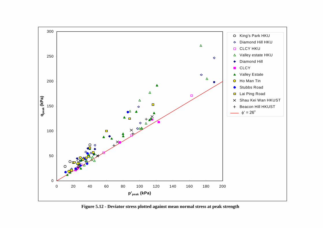
Figure 5.12 - Deviator stress plotted against mean normal stress at peak strength
0
50
100
150
200
250
300
0 20 40 60 80 100 120 140 160 180 200
p'peak (kPa)
qp
eak
(kP
a)King's Park HKUDiamond Hill HKUCLCY HKUValley estate HKUDiamond HillCLCYValley EstateHo Man TinStubbs RoadLai Ping RoadShau Kei Wan HKUSTBeacon Hill HKUSTφ' = 26o

Figure 5.13 – Void Ratio – Pressure Curves for Different Test Types on Different Specimen Types
Note: All specimens were initially compacted to 85% relative compaction (King’s Park)

Figure 5.14 - Critical state of unsaturated specimens of decomposed granitic soil in the plane of (a) specific volume and net mean stress, and (b) deviator stress and net mean stress (Ng & Chiu, 2002)
1.6
1.8
2.0
2.2
1 10 100 1000Net mean stress, p (kPa)
Spec
ific
volu
me,
v
Critical state line (s = 25 - 33 kPa)
Critical state line (s = 0 kPa)
Before shear
Critical state
ui1-gui1-g
ui2-g
ui3-g
ui4-g
ui2-g
ui3-g
ui4-g
0
100
200
300
400
500
0 50 100 150 200 250 300 350
Net mean stress, p (kPa)
Dev
iato
r stre
ss,q
(kPa
)
Critical state (s = 25 - 33 kPa)Critical state line (s = 25 - 33 kPa)Critical state line (s = 0 kPa)

Figure 5.15 - Relationship of soil suction (s) and apparent cohesion µ(s) (Ng & Chiu, 2001)
0
20
40
60
80
100
120
140
0 50 100 150 200 250 300 350
Suction, s (kPa)
decomposed volcanic soilkaolin (Wheeler & Sivakumar, 1995)decomposed fine ash tuff (Gan & Fredlund, 1996)
µ(s)

Figure 5.16 – Relationship between Martix Suction, Collapse Settlement and Time (Lee, 1997)

Figure 5.17 – Collapse Potential versus Moisture Content at Different Constant Relative Compaction (Lee, 1997)

Figure 5.18 – Relationship between Collapse Potential and Relative Compaction (Ng et al, 1998)

Figure 5.19 – Test Results on Indian Head Silt (Tadepalli & Fredlund, 1991)

Figure 6.1 – Information on Pre-1977 Fill Slopes Registered in the Hong Kong Government’s Slope Catalogue

Figure 6.2 – Profile of Void Ratio of Selected Pre-1977 Fill Slopes in Hong Kong
Figure 6.3 – Profile of Relative Compaction for Selected Pre-1977 Fill Slopes in Hong Kong

Figure 6.4 – Particle Size Distribution for Pre-1977 Fill Slopes in Hong Kong

Figure 6.5 – Profile of Atterberg Limits for Pre-1977 Fill Slopes in Hong Kong
Note: Total no. of samples = 129

Figure 6.6 – Profile of Degree of Saturation for Selected Pre-1977 Fill Slopes in Hong Kong

Figure 7.1 – Sliding of soil under nail head beams
Depth to failure surface
c lower SS
Failure surface
c upper SS

Figure 7.2 – Layout of surface grillage
Failure surface
Insitu material
Loose fill
c ss

Figure 7.3 – Normal stresses predicted by FLAC for a 10 m high 1 in 1.5 slope with 3 m depth of failing loose fill
0
20
40
60
80
100
0 1 2 3 4 5 6 7 8 9 10Vertical distance below crest of slope (m)
Stre
ss N
orm
al to
Slo
pe (k
Pa)
Cu = 5kPa
Cu = 2.5 to 7.5kPa
Cu = 7.5kPa
Cu = 2.5 to 15kPa
Cu = 10kPa
Cu = 5 to 15kPa
Cu = 15kPa
1.5110m
3m

Figure 7.4 – Calculation of surface pressure using limit equilibrium method
10m 1
1.5
Failure surface for maximum surface pressure
77 kPa
cu/p peak = 0.2
Loose fill
Insitu material
’
Triangular distribution of surface pressure between grillage and loose fill
Shear stress between grillage and loose fill

Figure 8.1 – Molenkamp’s Yield Surfaces in Octahedral Plane for Triaxial Compression (Hicks & Wong, 1988)
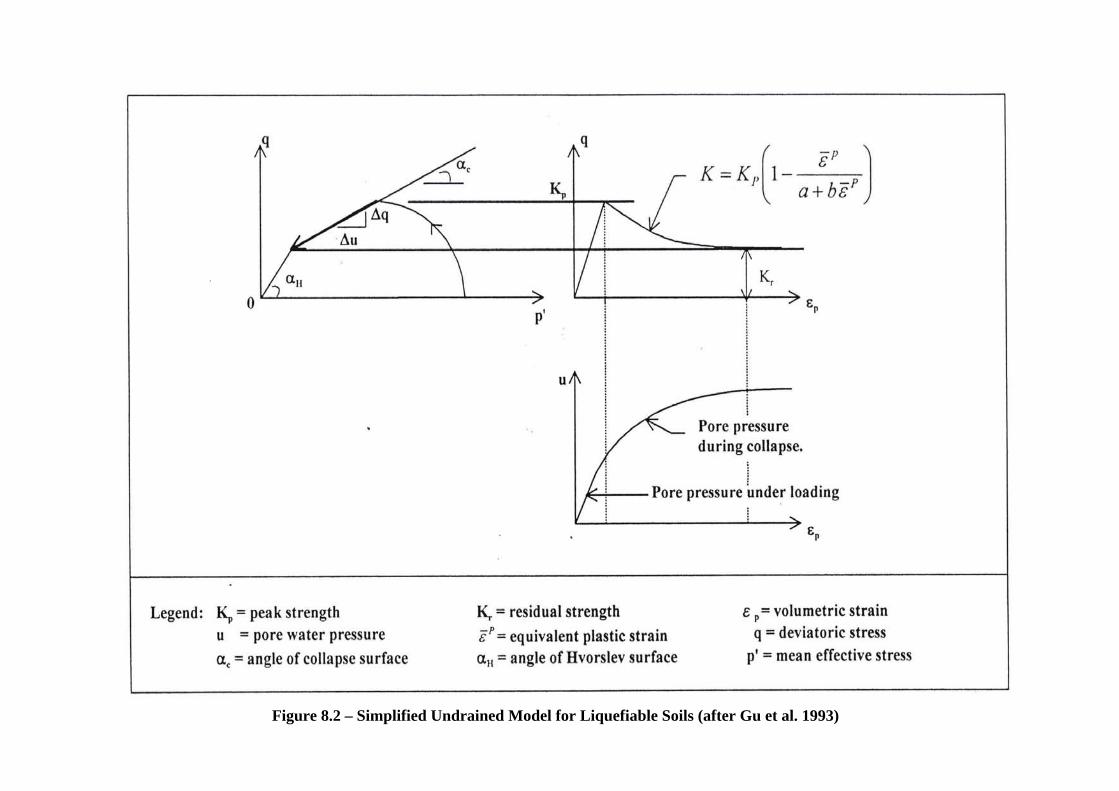
Figure 8.2 – Simplified Undrained Model for Liquefiable Soils (after Gu et al. 1993)
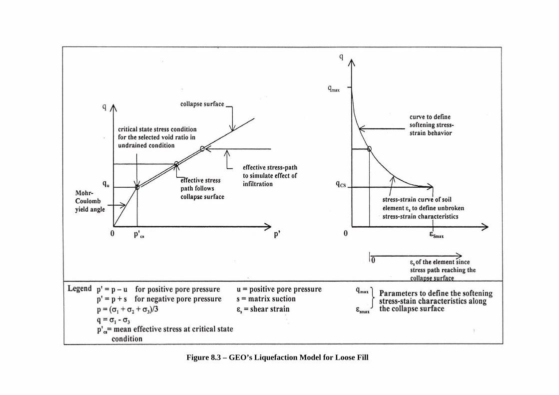
Figure 8.3 – GEO’s Liquefaction Model for Loose Fill

Figure 8.4 – Result of FLAC analyses of nailed loose fill slope - displacement vectors at failure or at prototype time 60 seconds (after Cheuk et al, 2001)
Maximum Vector: 6.87 m
Maximum Vector: 5.22 m (Failed at 22 Seconds)
Maximum Vector: 0.38 m
Maximum Vector: 0.33 m
a. Loose Fill Slope
b. Nailed Loose Fill Slope without Grid Facing
c. Nailed Loose Fill Slope with Grid Facing (EI=7 MPa-m4/m)
d. Nailed Loose Fill Slope with Grid Facing (EI=14 MPa-m4/m)
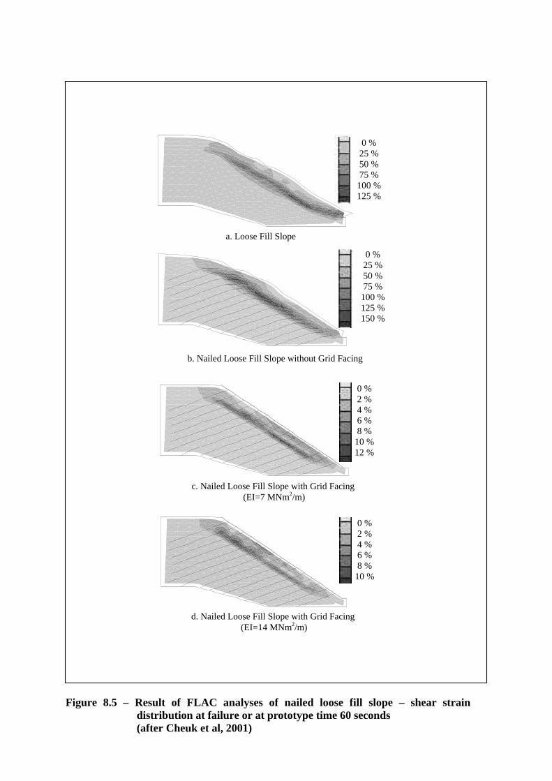
Figure 8.5 – Result of FLAC analyses of nailed loose fill slope – shear strain distribution at failure or at prototype time 60 seconds
(after Cheuk et al, 2001)
a. Loose Fill Slope(
b. Nailed Loose Fill Slope without Grid Facing
c. Nailed Loose Fill Slope with Grid Facing (EI=7 MNm2/m)
0 %25 %50 %75 %
100 %125 %
0 %2 %4 %6 %8 %
10 %12 %
0 %25 %50 %75 %
100 %125 %150 %
0 %2 %4 %6 %8 %
10 %
d. Nailed Loose Fill Slope with Grid Facing (EI=14 MNm2/m)

Figure 9.1 – Centrifuge Model Slope inside a Model Container (Ng et al. 2002b)

Figure 9.3 - Displacement Vectors in Soil-nailed CDG Fill Slope (Ng et al. 2002b)
24
.240
45°
6.24
0 0.600
18.900
Figure 9.2 - Displacement Vectors in Unreinforced CDG Fill Slope (Ng et al. 2002b)
24.2
40
45°
6.24
0 0.600
18.900