Embed Size (px)
Citation preview
User Manual for HE800ETN200
SmartStack Ethernet Module
28 October 2003 SUP0740-01


SUP0740-01 28 OCT 2003 PAGE 3 PREFACE
PREFACE This manual explains how to use the SmartStack Ethernet Module (ETN200). Copyright (C) 2003 Horner APG, LLC, 640 North Sherman Drive Indianapolis, Indiana 46201. All rights reserved. No part of this publication may be reproduced, transmitted, transcribed, stored in a retrieval system, or translated into any language or computer language, in any form by any means, electronic, mechanical, magnetic, optical, chemical, manual or otherwise, without the prior agreement and written permission of Horner APG, LLC. All software described in this document or media is also copyrighted material subject to the terms and conditions of the Horner Software License Agreement. Information in this document is subject to change without notice and does not represent a commitment on the part of Horner APG, LLC. Cscape, SmartStack, and CsCAN are trademarks of Horner APG, LLC. DeviceNet is a trademark of the Open DeviceNet Vendor Association (ODVA), Inc. Ethernet Global Data, EGD, Service Request Transfer Protocol, SRTP, CIMPLICITY and Series 90 are trademarks of GE Fanuc Automation North America, Inc. KEPware is a trademark of KEPware, Inc. NetX and ThreadX are trademarks of Express Logic, Inc. For user manual updates, contact Horner APG Technical Support Division, at (317) 916-4274 or visit our website at www.heapg.com.

PAGE 4 28 OCT 2003 SUP0740-01 PREFACE
LIMITED WARRANTY AND LIMITATION OF LIABILITY Horner APG, LLC ("HE-APG") warrants to the original purchaser that the SmartStack Ethernet Module manufactured by HE-APG is free from defects in material and workmanship under normal use and service. The obligation of HE-APG under this warranty shall be limited to the repair or exchange of any part or parts which may prove defective under normal use and service within two (2) years from the date of manufacture or eighteen (18) months from the date of installation by the original purchaser whichever occurs first, such defect to be disclosed to the satisfaction of HE-APG after examination by HE-APG of the allegedly defective part or parts. THIS WARRANTY IS EXPRESSLY IN LIEU OF ALL OTHER WARRANTIES EXPRESSED OR IMPLIED INCLUDING THE WARRANTIES OF MERCHANTABILITY AND FITNESS FOR USE AND OF ALL OTHER OBLIGATIONS OR LIABILITIES AND HE-APG NEITHER ASSUMES, NOR AUTHORIZES ANY OTHER PERSON TO ASSUME FOR HE-APG, ANY OTHER LIABILITY IN CONNECTION WITH THE SALE OF THIS SmartStack Ethernet Module. THIS WARRANTY SHALL NOT APPLY TO THIS SmartStack Ethernet Module OR ANY PART THEREOF THAT HAS BEEN SUBJECT TO ACCIDENT, NEGLIGENCE, ALTERATION, ABUSE, OR MISUSE. HE-APG MAKES NO WARRANTY WHATSOEVER IN RESPECT TO ACCESSORIES OR PARTS NOT SUPPLIED BY HE-APG. THE TERM "ORIGINAL PURCHASER", AS USED IN THIS WARRANTY, SHALL BE DEEMED TO MEAN THAT PERSON FOR WHOM THE SmartStack Ethernet Module IS ORIGINALLY INSTALLED. THIS WARRANTY SHALL APPLY ONLY WITHIN THE BOUNDARIES OF THE CONTINENTAL UNITED STATES. In no event, whether as a result of breach of contract, warranty, tort (including negligence) or otherwise, shall HE-APG or its suppliers be liable of any special, consequential, incidental or penal damages including, but not limited to, loss of profit or revenues, loss of use of the products or any associated equipment, damage to associated equipment, cost of capital, cost of substitute products, facilities, services or replacement power, down time costs, or claims of original purchaser's customers for such damages. To obtain warranty service, return the product to your distributor with a description of the problem, proof of purchase, post paid, insured and in a suitable package. ABOUT PROGRAMMING EXAMPLES Any example programs and program segments in this manual or provided on accompanying media are included solely for illustrative purposes. Due to the many variables and requirements associated with any particular installation, Horner APG cannot assume responsibility or liability for actual use based on the examples and diagrams. It is the sole responsibility of the system designer utilizing the SmartStack Ethernet Module to appropriately design the end system, to appropriately integrate the SmartStack Ethernet Module and to make safety provisions for the end equipment as is usual and customary in industrial applications as defined in any codes or standards which apply. Note: The programming examples shown in this manual are for illustrative purposes only.
Proper machine operation is the sole responsibility of the system integrator.

SUP0740-01 28 OCT 2003 PAGE 5 PREFACE
Table of Contents PREFACE..........................................................................................................................................3 LIMITED WARRANTY AND LIMITATION OF LIABILITY .....................................................................4 ABOUT PROGRAMMING EXAMPLES ...............................................................................................4
Table of Contents................................................................................................................................................................... 5 CHAPTER 1: INTRODUCTION ..........................................................................................................7
1.1 ETN200 Overview .................................................................................................................7 1.2 ETN200 System Requirements and Interoperability .................................................................8 1.3 ETN200 Specifications ...........................................................................................................8 1.4 Additional Technical Resources ..............................................................................................9
CHAPTER 2: INSTALLATION .........................................................................................................11 2.1 Internal ETN200 Module ......................................................................................................11 2.2 User-Installed ETN200 Module .............................................................................................11 2.3 Network Administrator Installation Notes ...............................................................................11
2.3.1 UDP and TCP Ports......................................................................................................12 2.3.2 EGD Unicast and Multicast IP Addressing ......................................................................12 2.3.3 Internet Connectivity .....................................................................................................12
CHAPTER 3: GENERAL CONFIGURATION ....................................................................................13 3.1 ETN200 Configuration .........................................................................................................13 3.2 ETN200 IP Address.............................................................................................................17
3.2.1 Static IP Address ..........................................................................................................17 3.2.2 Static IP Address with CAN ID.......................................................................................17 3.2.3 IP Address from OCS Register ......................................................................................17
CHAPTER 4: CSCAN OVER ETHERNET PROTOCOL .....................................................................19 4.1 CsCAN over Ethernet Overview ...........................................................................................19 4.2 CsCAN over Ethernet Configuration......................................................................................19 4.3 CsCAN over Ethernet Operation...........................................................................................20 4.4 CsCAN over Ethernet Downloading Precautions....................................................................20
4.4.1 How to Prevent Losing Communication..........................................................................21 4.4.2 How to Recover from Lost Communication.....................................................................21
4.5 CsCAN over Ethernet Security .............................................................................................22 CHAPTER 5: INTERNET CONTROL MESSAGE PROTOCOL (ICMP)...............................................25
5.1 ICMP Overview ...................................................................................................................25 5.2 ICMP Configuration .............................................................................................................25 5.3 ICMP Operation ..................................................................................................................26
CHAPTER 6: ETHERNET GLOBAL DATA PROTOCOL (EGD) ........................................................27 6.1 EGD Overview ....................................................................................................................27 6.2 EGD Terminology ................................................................................................................27 6.3 EGD Configuration ..............................................................................................................28 6.4 EGD Produced Exchange Configuration ...............................................................................30
6.4.1 Creating EGD Produced Exchanges ..............................................................................31 6.4.2 Defining EGD Produced Exchange I/O Blocks ................................................................32
6.5 EGD Consumed Exchange Configuration..............................................................................33 6.5.1 Creating EGD Consumed Exchanges ............................................................................34 6.5.2 Defining EGD Consumed Exchange I/O Blocks ..............................................................35
6.6 EGD Operation....................................................................................................................36 6.7 EGD Status Words ..............................................................................................................36
6.7.1 EGD Produced Exchange Status Words ........................................................................36 6.7.2 EGD Consumed Exchange Status Words .......................................................................37
6.8 EGD Example 1 ..................................................................................................................38 6.8.1 EGD Example 1 – Configuring Node 1 ...........................................................................38 6.8.2 EGD Example 1 – Configuring Node 2 ...........................................................................42 6.8.3 EGD Example 1 – Starting EGD Communication between Node 1 and Node 2.................46
6.9 EGD Example 2 ..................................................................................................................47

PAGE 6 28 OCT 2003 SUP0740-01 PREFACE
6.9.1 EGD Example 2 – Adding a Status Block .......................................................................47 6.9.2 EGD Example 2 – Adding an OCS Timestamp Block ......................................................48 6.9.3 EGD Example 2 – Adding a Filler Block..........................................................................49
CHAPTER 7: SERVICE REQUEST TRANSFER PROTOCOL (SRTP) ...............................................51 7.1 SRTP Overview...................................................................................................................51 7.2 SRTP Configuration.............................................................................................................52 7.3 SRTP Operation..................................................................................................................52
CHAPTER 8: MODBUS TCP SLAVE PROTOCOL ...........................................................................53 8.1 Modbus Overview................................................................................................................53 8.2 Modbus Configuration..........................................................................................................54 8.3 Modbus Operation...............................................................................................................54
INDEX .............................................................................................................................................55

SUP0740-01 28 OCT 2003 PAGE 7 CH. 1
CHAPTER 1: INTRODUCTION 1.1 ETN200 Overview The SmartStack Ethernet Module (HE800ETN200) provides the Horner APG OCS / RCS family of products with Ethernet communication capability. Please note that for some OCS models, such as OCS451, OCS551 and OCS651, the ETN200 Ethernet module is built-in, while for other OCS models, such as OCS110, OCS210, OCS250 and RCS250, the ETN200 module is user-installed, just like any other SmartStack I/O module. In either case, the ETN200 supports the following application protocols:
• CsCAN TCP Server - Horner APG CsCAN over Ethernet • ICMP - Internet Control Message Protocol (Ping) • EGD - GE Fanuc Ethernet Global Data (Peer to Peer) • SRTP Server - GE Fanuc Service Request Transfer Protocol • Modbus TCP Slave - Modbus over Ethernet
ETN200 module configuration is done through Cscape Programming Software. Figure 1.1 illustrates an example of a network containing ETN200 modules.
Figure 1.1 – Example of an Ethernet Network
CCU (Conveyer Controller)
RCS Mini OCS OCS
OCS #1
ETN200
ETHERNET HUB
Series 90-30
CAT5 Ethernet Cable
CsCAN or DeviceNet Network
Note: An Ethernet Hub or Multicast Router is required. Switches are not recommended for Ethernet Global Data (EGD) protocol, because they may not be able to pass multicast messages.
Note: This device cannot be used in a DeviceNet Network.
ETN200
OCS #2 PC
(Running Cscape)
Series 90-30 CPU364
Group X
CAN Cable
CDC200

PAGE 8 28 OCT 2003 SUP0740-01 CH. 1
1.2 ETN200 System Requirements and Interoperability Full Ethernet functionality, as described in this user manual, requires:
• OCS or RCS controller with internal or user-installed ETN200 SmartStack Ethernet Module • PC running Cscape Programming Software Version 6.10 or later
Specifically, older SmartStack Ethernet Modules, such as the ETN100 and ETN116, do not support the following features: CsCAN over Ethernet protocol, 100 MHz Fast Ethernet, and Full Duplex mode. In addition, older modules do not support some of the EGD and SRTP protocol features described in this user manual. As of the writing of this manual, the server protocols, supported by the ETN200 SmartStack Ethernet Module, have been tested for interoperability with Cscape and several 3rd party client software packages, as shown in Table 1.1.
Table 1.1 – ETN200 Server Protocol Interoperability Client Software Package ETN200 Server Protocol
Name Version CsCAN SRTP Modbus Cscape Programming Software 6.10 √
CIMPLICITY Human Machine Interface (HMI) 3.2 √ 5.0 √
CIMPLICITY Plant Edition (PE) 6.1 √ √
KEPware Enhanced OPC / DDE Server 4.84.227 √ √ 1.3 ETN200 Specifications
Table 1.2 – Specifications
General
Ethernet Speeds 10 BaseT Ethernet (10 MHz)
100 BaseTx Fast Ethernet (100 MHz)
Ethernet Modes Half or Full Duplex
Ethernet Auto-Negotiation Both 10 / 100 MHz and Half / Full Duplex
Ethernet Connector Type Shielded RJ-45
Application Protocols
ICMP Ping Only
CsCAN TCP Server Maximum Connections = 8
EGD (Ethernet Global Data) Maximum Exchanges = 127
Maximum Bytes per Exchange = 1,400
SRTP Server Maximum Connections = 16
Modbus TCP Slave Maximum Connections = 16

SUP0740-01 28 OCT 2003 PAGE 9 CH. 1
1.4 Additional Technical Resources It is assumed that the user has a working knowledge of Ethernet networks and Horner OCS / RCS controllers. The following references are available to assist the user in these areas. For a technical summary of Ethernet and other information, refer to:
www.techfest.com/networking/lan/ethernet.htm For Horner OCS / RCS controller technical support, refer to:
www.heapg.com/Support/index.htm
For additional assistance, contact Technical Support at the following locations. Please visit our website for manual updates. North America: (317) 916-4274 www.heapg.com
Europe: (+) 353-21-4321-266 www.horner-apg.com

PAGE 10 28 OCT 2003 SUP0740-01 CH. 1
NOTES

SUP0740-01 28 OCT 2003 PAGE 11 CH. 2
CHAPTER 2: INSTALLATION 2.1 Internal ETN200 Module For SVGA color graphics OCS models, such as OCS451, OCS551 and OCS651, the ETN200 SmartStack Ethernet module is internal to the OCS unit, requiring no user-installation. Figure 2.1 shows the location of the Ethernet RJ-45 connector on SVGA color graphics units.
Ethernet Connector (OCS551 and OCS651) Ethernet Connector (OCS451)
Figure 2.1 – SVGA Color Graphics OCS Bottom View 2.2 User-Installed ETN200 Module For other OCS or RCS models, the ETN200 SmartStack Ethernet module must be user-installed on the back of the OCS / RCS unit. Figure 2.2 shows the locations of the Ethernet RJ-45 connector and LED indicators on the user-installed ETN200 SmartStack Ethernet module. Note: Normally, a user-installed ETN200 module occupies the first I/O slot on the back of the OCS / RCS
unit. The only exception to this rule occurs if a FOX100 module is also installed. In this case, the FOX100 module occupies the first I/O slot, and the ETN200 is installed into the second I/O slot.
For more details on installing SmartStack I/O modules, refer to Chapter 2 of the Control Station Hardware Manual (MAN0227), which also provides a handy checklist concerning panel box layout and minimum clearance requirements. Link & Activity LEDs Ethernet Connector
Figure 2.2 – ETN200 SmartStack Ethernet Module Side View 2.3 Network Administrator Installation Notes When connecting an ETN200 module to a local network, the following information is provided to the Network Administrator, as an aid in configuring Ethernet Hubs, Routers, Switches, and Servers.
Caution: For proper functioning and to avoid possible damage, do not install more than four SmartStack Modules on the back of an OCS or RCS controller.

PAGE 12 28 OCT 2003 SUP0740-01 CH. 2
2.3.1 UDP and TCP Ports Each protocol supported by the ETN200 module (except ICMP) uses either a UDP Port or a TCP Port as the destination for all messaging, as shown in Table 2.1.
Table 2.1 – ETN200 Protocol UDP and TCP Ports UDP Port TCP Port ETN200 Protocol
Hexadecimal Decimal Hexadecimal Decimal CsCAN 4845 18501
EGD 4746 18246 SRTP 4745 18245
Modbus 01F6 502 2.3.2 EGD Unicast and Multicast IP Addressing When using Ethernet Global Data (EGD) protocol for peer-to-peer communication, there are two methods for sending data: (1) send to a single device or (2) send to a group of devices. When sending to a single device (method 1), EGD protocol uses Unicast IP Addressing. This means that the IP header’s 32-bit Destination IP Address will contain the intended recipient’s unique IP Address. When sending to a group of devices (method 2), EGD protocol uses Multicast IP Addressing. This means that the IP header’s 32-bit Destination IP Address will contain one of the 32 Multicast IP Addresses shown in Table 2.2.
Table 2.2 – EGD Multicast IP Addressing Group ID Multicast IP Address
1 224.0.7.1 2 224.0.7.2 : :
: :
32 224.0.7.32 Ethernet Switches normally don’t support Multicast IP Addressing, while Ethernet Hubs do support Multicast IP Addressing. Some Ethernet Routers, known as Multicast Routers, do support Multicast IP Addressing, by using Internet Group Management Protocol (IGMP). Note: For those customers wanting to use Multicast Routers to connect EGD devices, the ETN200
Module automatically handles IGMP communication with Multicast Routers. For more information regarding EGD protocol, refer to Chapter 6 of this manual. 2.3.3 Internet Connectivity Since the ETN200 uses a standard TCP/IP protocol stack (powered by NetX and ThreadX), it can communicate beyond the local network, and on the Internet, for all protocols except EGD. To do so, the ETN200 must be configured with the IP Address of a Network Gateway server, which allows communication outside the local network. See Default Gateway configuration under step 5 of Section 3.1 (page 15) in this manual for details. Note: As network complexity increases, due to Ethernet Hubs, Routers, Switches, Gateways, and the
Internet, the worst-case network delay increases. In many cases, the client software must be configured to account for this time lag. For example, Cscape’s Timeout can be adjusted as shown under step 2 of Section 4.2 (page 19) in this manual.

SUP0740-01 28 OCT 2003 PAGE 13 CH. 3
CHAPTER 3: GENERAL CONFIGURATION Note: The following configuration is required for all applications regardless of the protocols used. Additional configuration procedures must be performed for each protocol used as described in the configuration sections in the following chapters. 3.1 ETN200 Configuration To configure the ETN200 SmartStack Ethernet Module, using Cscape Programming Software, perform the following six steps: 1. On the main Cscape screen, select the Controller menu and its I/O Configure sub-menu to open the
I/O Configuration dialog (Figure 3.1 or Figure 3.2). 2. If configuring a different OCS controller model than the one shown in the I/O Configuration dialog,
click on the topmost Config button, select the desired OCS controller model, and then click OK. Note: Figure 3.1 shows a typical I/O Configuration dialog for OCS models, which have standard FOX100
and ETN200 modules installed internally. For these models, step 3 should be skipped.
Figure 3.2 shows a typical I/O Configuration dialog for other OCS models, in which the ETN200 module is a user-installable option. For these models, step 3 must be performed, to configure the ETN200 module into a SmartStack I/O slot.
Figure 3.1 – I/O Configuration Dialog – OCS Models With Internally-Installed ETN200
Figure 3.2 – I/O Configuration Dialog – OCS Models With User-Installable ETN200
PAGE 14 28 OCT 2003 SUP0740-01 CH. 3
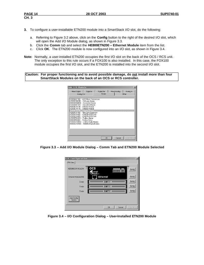
3. To configure a user-installable ETN200 module into a SmartStack I/O slot, do the following:
a. Referring to Figure 3.2 above, click on the Config button to the right of the desired I/O slot, which will open the Add I/O Module dialog, as shown in Figure 3.3.
b. Click the Comm tab and select the HE800ETN200 – Ethernet Module item from the list. c. Click OK. The ETN200 module is now configured into an I/O slot, as shown in Figure 3.4.
Note: Normally, a user-installed ETN200 occupies the first I/O slot on the back of the OCS / RCS unit.
The only exception to this rule occurs if a FOX100 is also installed. In this case, the FOX100 module occupies the first I/O slot, and the ETN200 is installed into the second I/O slot.
Figure 3.3 – Add I/O Module Dialog – Comm Tab and ETN200 Module Selected
Figure 3.4 – I/O Configuration Dialog – User-Installed ETN200 Module
Caution: For proper functioning and to avoid possible damage, do not install more than four SmartStack Modules on the back of an OCS or RCS controller.
SUP0740-01 28 OCT 2003 PAGE 15 CH. 3
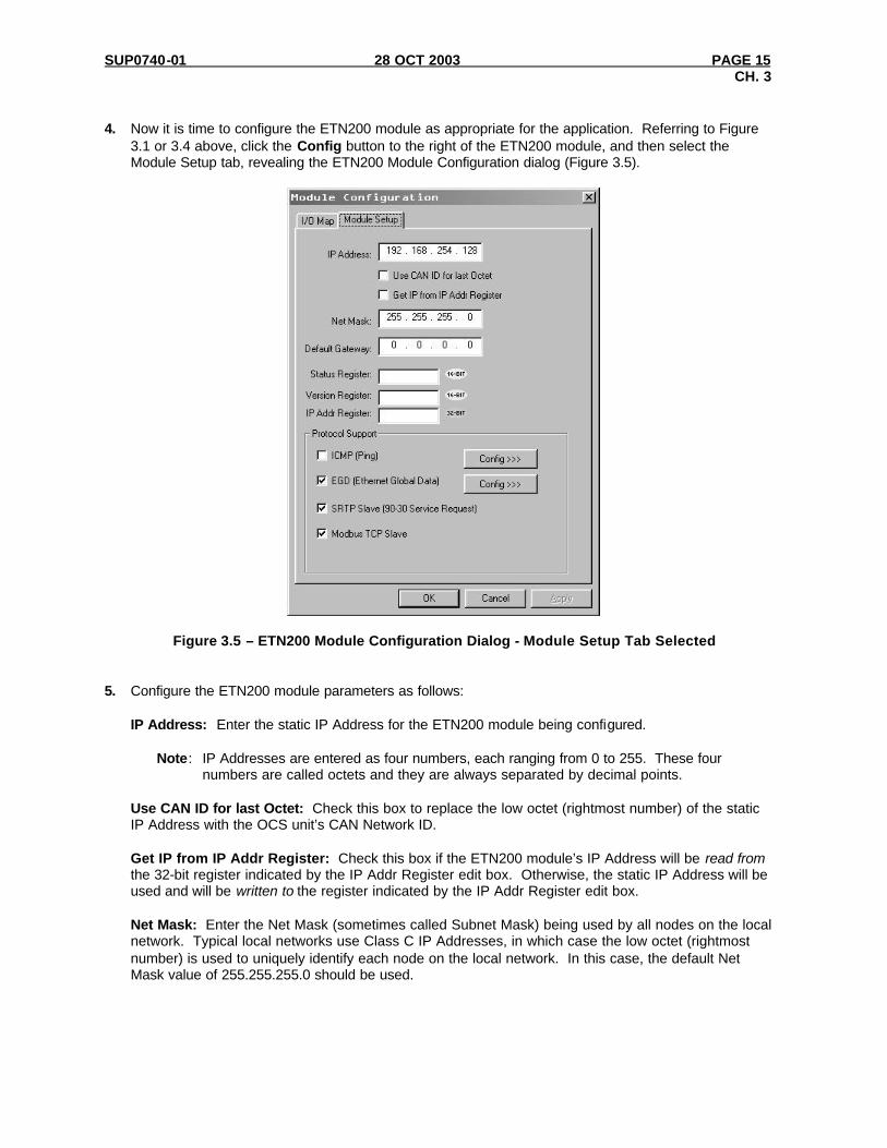
4. Now it is time to configure the ETN200 module as appropriate for the application. Referring to Figure
3.1 or 3.4 above, click the Config button to the right of the ETN200 module, and then select the Module Setup tab, revealing the ETN200 Module Configuration dialog (Figure 3.5).
Figure 3.5 – ETN200 Module Configuration Dialog - Module Setup Tab Selected 5. Configure the ETN200 module parameters as follows:
IP Address: Enter the static IP Address for the ETN200 module being configured.
Note: IP Addresses are entered as four numbers, each ranging from 0 to 255. These four numbers are called octets and they are always separated by decimal points.
Use CAN ID for last Octet: Check this box to replace the low octet (rightmost number) of the static IP Address with the OCS unit’s CAN Network ID.
Get IP from IP Addr Register: Check this box if the ETN200 module’s IP Address will be read from the 32-bit register indicated by the IP Addr Register edit box. Otherwise, the static IP Address will be used and will be written to the register indicated by the IP Addr Register edit box.
Net Mask: Enter the Net Mask (sometimes called Subnet Mask) being used by all nodes on the local network. Typical local networks use Class C IP Addresses, in which case the low octet (rightmost number) is used to uniquely identify each node on the local network. In this case, the default Net Mask value of 255.255.255.0 should be used.
PAGE 16 28 OCT 2003 SUP0740-01 CH. 3
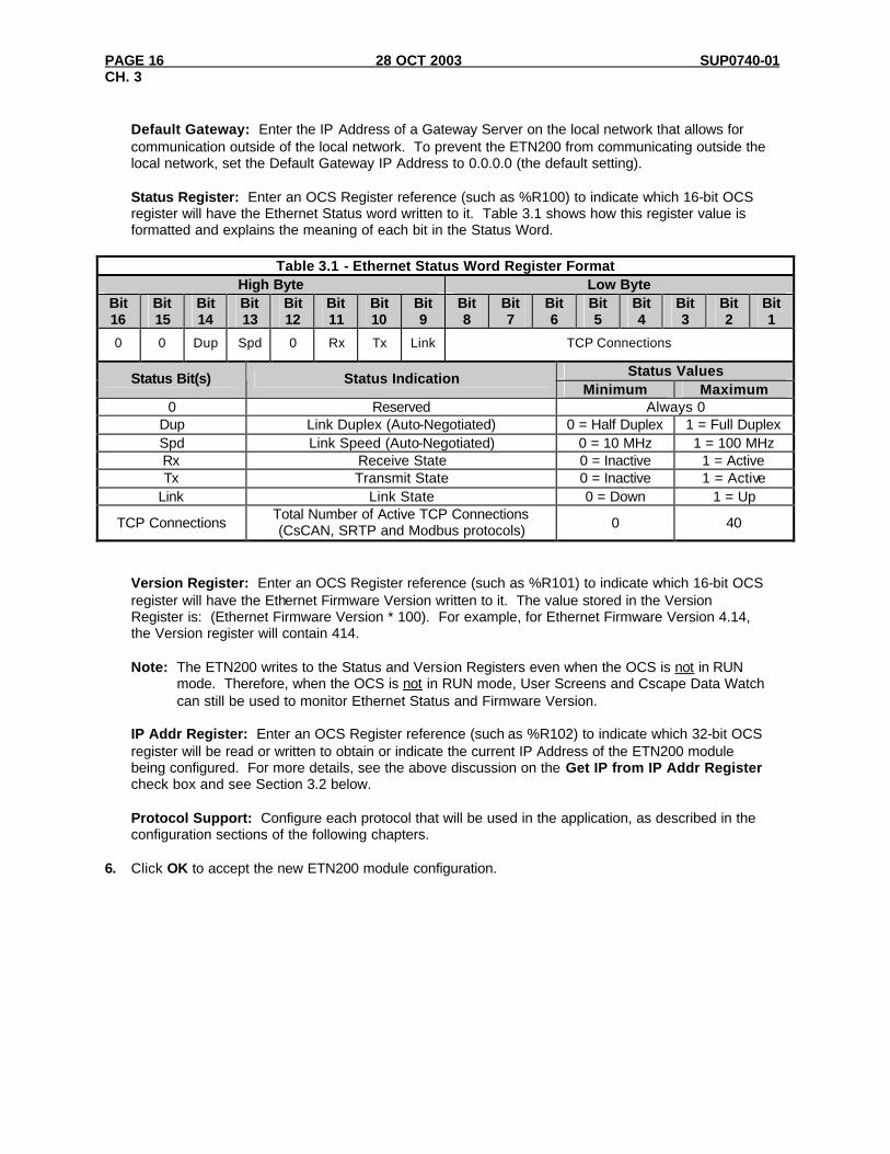
Default Gateway: Enter the IP Address of a Gateway Server on the local network that allows for communication outside of the local network. To prevent the ETN200 from communicating outside the local network, set the Default Gateway IP Address to 0.0.0.0 (the default setting). Status Register: Enter an OCS Register reference (such as %R100) to indicate which 16-bit OCS register will have the Ethernet Status word written to it. Table 3.1 shows how this register value is formatted and explains the meaning of each bit in the Status Word.
Table 3.1 - Ethernet Status Word Register Format
High Byte Low Byte Bit 16
Bit 15
Bit 14
Bit 13
Bit 12
Bit 11
Bit 10
Bit 9
Bit 8
Bit 7
Bit 6
Bit 5
Bit 4
Bit 3
Bit 2
Bit 1
0 0 Dup Spd 0 Rx Tx Link TCP Connections
Status Values Status Bit(s) Status Indication Minimum Maximum
0 Reserved Always 0 Dup Link Duplex (Auto-Negotiated) 0 = Half Duplex 1 = Full Duplex Spd Link Speed (Auto-Negotiated) 0 = 10 MHz 1 = 100 MHz Rx Receive State 0 = Inactive 1 = Active Tx Transmit State 0 = Inactive 1 = Active
Link Link State 0 = Down 1 = Up
TCP Connections Total Number of Active TCP Connections (CsCAN, SRTP and Modbus protocols) 0 40
Version Register: Enter an OCS Register reference (such as %R101) to indicate which 16-bit OCS register will have the Ethernet Firmware Version written to it. The value stored in the Version Register is: (Ethernet Firmware Version * 100). For example, for Ethernet Firmware Version 4.14, the Version register will contain 414. Note: The ETN200 writes to the Status and Version Registers even when the OCS is not in RUN
mode. Therefore, when the OCS is not in RUN mode, User Screens and Cscape Data Watch can still be used to monitor Ethernet Status and Firmware Version.
IP Addr Register: Enter an OCS Register reference (such as %R102) to indicate which 32-bit OCS register will be read or written to obtain or indicate the current IP Address of the ETN200 module being configured. For more details, see the above discussion on the Get IP from IP Addr Register check box and see Section 3.2 below. Protocol Support: Configure each protocol that will be used in the application, as described in the configuration sections of the following chapters.
6. Click OK to accept the new ETN200 module configuration.

SUP0740-01 28 OCT 2003 PAGE 17 CH. 3
3.2 ETN200 IP Address The ETN200 module obtains its IP Address in one of three different ways, depending on how the Use CAN ID for last Octet and the Get IP from IP Addr Register checkboxes (Figure 3.5) are configured, as described in the following three sections. 3.2.1 Static IP Address
q Use CAN ID for last Octet q Get IP from IP Addr Register
In this mode, the ETN200 module’s IP Address comes from the IP Address parameter only, and does not use the CAN Network ID for the low octet and does not use IP Addr Register to obtain an IP Address from an OCS register. In this case the ETN200 module writes the static IP Address to the 32-bit OCS register indicated by the IP Addr Register parameter. 3.2.2 Static IP Address with CAN ID ü Use CAN ID for last Octet q Get IP from IP Addr Register
In this mode, the ETN200 module’s IP Address comes from a combination of the IP Address parameter and the OCS/RCS CAN Network ID. The most significant (leftmost) three octets of the IP Address come from the IP Address parameter. The least significant (rightmost) octet of the IP Address is taken from the OCS (or RCS) CAN Network ID. In this case the ETN200 module writes the adjusted IP Address to the 32-bit OCS register indicated by the IP Addr Register parameter. 3.2.3 IP Address from OCS Register
q Use CAN ID for last Octet ü Get IP from IP Addr Register
In this mode, the ETN200 module’s IP Address comes from an OCS register. The IP Addr Register parameter indicates which 32-bit OCS register to read the IP Address from. The static IP Address parameter is not used in this situation, except to set the Default IP Address in non-volatile memory. Note: Every time an I/O configuration is successfully downloaded to an OCS with an ETN200 module,
the static IP Address parameter is stored in non-volatile memory as the Default IP Address. This Default IP Address will be used by the ETN200 in the event of a future unsuccessful I/O configuration download. This is done in an effort to minimize loss of communication requiring direct on-site intervention to correct.

PAGE 18 28 OCT 2003 SUP0740-01 CH. 3
NOTES

SUP0740-01 28 OCT 2003 PAGE 19 CH. 4
CHAPTER 4: CSCAN OVER ETHERNET PROTOCOL 4.1 CsCAN over Ethernet Overview This chapter describes CsCAN TCP Server Communication Protocol, also known as CsCAN over Ethernet protocol. CsCAN over Ethernet protocol allows a CsCAN Host Programming Tool, such as Cscape, to access an OCS unit, as though it were connected directly to the OCS programming serial port. 4.2 CsCAN over Ethernet Configuration The ETN200 module requires no protocol-specific configuration for CsCAN over Ethernet protocol. Only the general ETN200 Module Configuration previously described in Chapter 3 is required. As long as the ETN200 module has been assigned an IP Address and Net Mask, it will automatically respond to CsCAN over Ethernet messages sent to it by a PC running Cscape. To connect Cscape to an OCS unit’s ETN200 module, using CsCAN over Ethernet protocol, perform the following two steps: 1. On the main Cscape screen, select the Tools menu and its Options sub-menu to open the Program
Options dialog (Figure 4.1).
Figure 4.1 – Program Options Dialog – Communications Port Tab and Ethernet Selected 2. Select the Communication Ports tab, select Ethernet from the Comm Ports list, and then set the
Target IP Address and Timeout parameters as follows:

PAGE 20 28 OCT 2003 SUP0740-01 CH. 4
Target IP Address: Enter the IP Address previously assigned to the ETN200 module. Please refer to Chapter 3 regarding how to assign an IP Address to an ETN200 module. Timeout: Enter a number between 1000 and 65,000 (in milliseconds) for the maximum expected network round-trip communication time. This value determines how long Cscape will wait for a response after it sends a CsCAN over Ethernet protocol command to the ETN200. Note: For most local network applications, the default Timeout value of 1000 is sufficient.
However, there are some network considerations, which may require the Timeout value to be increased to facilitate reliable communication. This includes heavily loaded networks, complex networks with multiple levels of routers and switches, and Internet communication.
Also, because CsCAN communication is affected by ladder code scan rate, the Timeout value may have to be further increased to compensate for applications with very slow scan rates.
4.3 CsCAN over Ethernet Operation As stated previously, the ETN200 module allows a CsCAN Host Programming Tool, such as Cscape, to use CsCAN over Ethernet to perform all standard supervisory control, monitoring and programming functions with the OCS, as though it were connected directly to the OCS programming serial port. These standard supervisory functions include the ETN200 module’s ability to handle pass-through communication with the CsCAN Nodes attached to the OCS CAN port. This feature is known as CsCAN single-point programming. For example, referring back to Figure 1.1(page 7) the PC (running Cscape) can use OCS #1’s ETN200 module as a gateway, to easily access all of the CsCAN Nodes on OCS #1’s CAN network. Note: Single-point programming only works if the OCS CAN network is being used for CsCAN
communication and does not work for DeviceNet. 4.4 CsCAN over Ethernet Downloading Precautions When downloading a new ETN200 configuration to a target OCS, using CsCAN over Ethernet protocol, extra care should be taken. In particular, when downloading I/O and Network Configuration, the ETN200 module configuration is also downloaded, which has the potential to change the target device’s IP Address, or it could even remove the ETN200 module configuration entirely, resulting in loss of communication and a failed download. For this reason, when the Cscape user modifies the I/O Configuration, and then starts to download it using CsCAN over Ethernet, Cscape issues a warning message, as shown in Figure 4.2.
Figure 4.2 – I/O Configuration Download Warning

SUP0740-01 28 OCT 2003 PAGE 21 CH. 4
4.4.1 How to Prevent Losing Communication Before using CsCAN over Ethernet to download a new I/O Configuration, to an OCS with an ETN200 installed, the application programmer should:
1. Make sure the new I/O Configuration contains an ETN200 configuration. 2. Make sure the new ETN200 configuration will not change the IP Address.
Refer to Chapter 3 of this manual on how to check and/or correct ETN200 module configuration and pay particular attention to step 5 of the ETN200 configuration process in Section 3.1 (page 15), and to Section 3.2 (page 17), which explains in detail how the ETN200 module obtains an IP Address. If the new ETN200 module configuration specifies Static IP Address (Section 3.2.1 [page 17]), make sure the IP Address parameter (Figure 3.5 [page 15]) matches Cscape’s Target IP Address (Figure 4.1). If the new ETN200 module configuration specifies Static IP Address with CAN ID (Section 3.2.2 [page 17]), make sure the IP Address, which will be built from the combination of the IP Address parameter (Figure 3.5 [page 15]) and the OCS/RCS CAN Network ID, matches Cscape’s Target IP Address (Figure 4.1). If the new ETN200 module configuration specifies IP Address from OCS Register (Section 3.2.3 [page 17]), make sure the OCS register indicated by the IP Addr Register parameter (Figure 3.5 [page 15]) contains an IP Address, and that it matches Cscape’s Target IP Address (Figure 4.1). If necessary, use Cscape’s Data Watch facility to set the OCS register to the correct IP Address before downloading. 4.4.2 How to Recover from Lost Communication If the ETN200 module’s IP Address changes as a result of using CsCAN over Ethernet to download a new user program, activity will halt at the end of the I/O Configuration download, and communication between Cscape and the target OCS will be lost. Then, after several seconds, Cscape will display a Communication Timeout error. If this happens, it is possible to recover Cscape communication with the target OCS, as follows:
1. Referring to Chapter 3 of this manual (especially Section 3.2 [page 17]) and to Section 4.4.1 above, determine the ETN200 module’s new IP Address, by using Cscape to re-examine the I/O Configuration just downloaded.
2. Referring to Figure 4.1, change Cscape’s Target IP Address to match the ETN200 module’s new IP Address.
3. Try performing the download again. 4. If this does not succeed, try changing Cscape’s Target IP Address (Figure 4.1) to match the
static IP Address parameter (even if it is grayed out). 5. If all else fails, connect a PC running Cscape directly to the target OCS unit’s programming serial
port, repeat the download, and then use Data Watch to examine the register indicated by the IP Addr Register parameter (Figure 3.5 [page 15]), to discover the ETN200 module’s new IP Address.
Note: If the application programmer wants to use CsCAN over Ethernet to intentionally change an
ETN200 module’s IP Address, do this by (1) starting the download, (2) waiting for Cscape to timeout and (3) performing steps 1, 2 and 3 of the recovery process, as described above.

PAGE 22 28 OCT 2003 SUP0740-01 CH. 4
4.5 CsCAN over Ethernet Security To prevent the use of CsCAN over Ethernet protocol to gain unauthorized access to an OCS or RCS, Cscape Programming Software and OCS Ethernet Firmware have the ability to password-protect CsCAN over Ethernet communication. To implement CsCAN over Ethernet Security, use Cscape Programming Software, to perform the following nine steps: 1. Open the user program previously created for the target OCS or RCS controller. 2. If the user program has already been set up with security passwords, first log-in as the Administrator.
To do this, select the Tools menu and its Security sub-menu, click Log-in, enter the Administrator password, and then click OK. Cscape will then acknowledge the Administrator log-in; click OK again.
3. On the main Cscape screen, select the Tools menu and its Security sub-menu, and then click
Change Passwords, to open the Security Passwords dialog, as shown in Figure 4.3.
Figure 4.3 – Security Passwords Dialog 4. Click on the View Passwords button to view the Administrator and User passwords. 5. Change passwords and user names as desired for the application. Note that passwords are numeric
values between 1 and 999,999, while the user names can be any text from 1 to 15 characters long. 6. Click on the Items to Protect Setup button to open the Administrator’s Security Settings dialog, as
shown in Figure 4.4.
Figure 4.4 – Administrator’s Security Settings Dialog

SUP0740-01 28 OCT 2003 PAGE 23 CH. 4
7. To password-protect CsCAN over Ethernet protocol, make sure the CsCAN TCP (Ethernet)
checkbox is checked in the Administrator’s Security Settings dialog, as shown in Figure 4.4. Then click OK.
8. The Administrator password is always authorized for all protected features. If desired, one or more of
the user passwords can also be authorized for CsCAN over Ethernet communication. To do this, refer to Figure 4.3 and click one of the User Permissions Setup buttons to open that user’s Security Settings dialog, which will be similar to Figure 4.4. Then check the CsCAN TCP (Ethernet) checkbox and click OK.
9. After downloading the user program to the target OCS or RCS, both Cscape and the OCS (or RCS)
controller will enforce the new password security for CsCAN over Ethernet protocol.

PAGE 24 28 OCT 2003 SUP0740-01 CH. 4
NOTES

SUP0740-01 28 OCT 2003 PAGE 25 CH. 5
CHAPTER 5: INTERNET CONTROL MESSAGE PROTOCOL (ICMP) 5.1 ICMP Overview ICMP is used for diagnostic purposes only, to determine if another device exists on the Ethernet network. Using ICMP, the ETN200 sends Ping Echo Requests to another device, and expects the other device to answer with Ping Echo Responses. The ETN200 module measures the round-trip time of each Ping Echo Request / Response exchange and puts the result (in milliseconds) into an OCS register. In addition, when the ETN200 receives a Ping Echo Request from another device, it answers with a Ping Echo Response. Note: Although ICMP supports other network diagnostics, the ETN200 module only supports Ping. 5.2 ICMP Configuration If ICMP Protocol will be used in the application, ICMP Configuration must be performed, in addition to the general ETN200 Module Configuration previously described in Chapter 3. To configure ICMP Protocol, use Cscape Programming Software, to perform the following five steps: 1. Open the ETN200 Module Configuration dialog (Figure 3.5 [page 15]), as described in Chapter 3. 2. Enable ICMP by checking the ICMP (Ping) checkbox in the Module Configuration dialog (Figure 3.5). 3. Click on the Config button next to the ICMP (Ping) checkbox to open the ICMP Configuration dialog
(Figure 5.1).
Figure 5.1 – ICMP Configuration Dialog 4. Configure the ICMP Configuration parameters as follows:
Ping IP Reg: Enter an OCS Register reference (such as %R200) to indicate which 32-bit OCS register will be read to obtain the IP Address of the network device to send Ping Echo Requests to. Ping Time Reg: Enter an OCS Register reference (such as %R202) to indicate which 32-bit OCS register will be written with the Ping Echo Request / Response round-trip time (in milliseconds). Ping Timeout: Enter a number between 100 and 100,000 for how often (in milliseconds) the ETN200 should send Ping Echo Requests.
5. Click OK to accept the new ICMP Configuration.

PAGE 26 28 OCT 2003 SUP0740-01 CH. 5
5.3 ICMP Operation To start Ping Echo Requests, use Ladder Code, User Screens or Cscape Data Watch to write an IP Address to the OCS register indicated by Ping IP Reg. To check the resulting Ping Echo Response times, read the OCS register indicated by Ping Time Reg. If the round-trip time exceeds the configured Ping Timeout (or if there is no response at all), the reported response time will be -1. To stop Ping Echo Requests, write 0.0.0.0 to the OCS register indicated by Ping IP Reg. Note that in the ETN200, ICMP protocol is active even when the OCS is not in RUN mode. Therefore, when the OCS is not in RUN mode, User Screens and Cscape Data Watch can still be used to control and monitor ICMP Pinging.
SUP0740-01 28 OCT 2003 PAGE 27 CH. 6
CHAPTER 6: ETHERNET GLOBAL DATA PROTOCOL (EGD) 6.1 EGD Overview Ethernet Global Data Protocol (EGD) is a GE Fanuc Automation protocol, which is designed for simple, efficient data exchanges between peer devices on a network. EGD protocol communicates using the UDP transport layer. Although this method of data transfer is very efficient, it has no built-in way to detect and recover lost data packets. However, since all EGD data transfers are periodic, lost data packets will be repeated when their user-configured time periods expire. Caution: EGD protocol is not intended for one-shot event notification or for applications with critical
data, which can’t withstand being delayed as described above. Each device on an EGD network can be configured as a Producer, as a Consumer, or both. A Producer is a device that transmits Exchanges (blocks of data) to one or more Consumers. A Consumer is a device that receives Exchanges from one or more Producers. A Producer can transmit Exchanges directly to a specific Consumer, by sending them to the Consumer’s IP Address (using Unicast IP Addressing). A Producer can also transmit Exchanges to a Group of Consumers, by sending them to a Group ID (using Multicast IP Addressing). See Section 2.3.2 (page 12) for more details regarding Unicast and Multicast IP Addressing. An ETN200 module supports up to 127 concurrent Exchanges, each of which can be either a Producer or a Consumer of data. 6.2 EGD Terminology Before configuring an ETN200 module for EGD protocol, it is essential that the application programmer understand the key EGD terms, which are shown in Table 6.1.
Table 6.1 – EGD Terminology Term Definition
Exchange A block of data sent by a Producer and received by one or more Consumers
Exchange Number A number (1 to 16,383), which along with the IP Address of the Producer, is used to uniquely identify an Exchange on an EGD network
Producer An EGD network device configured to transmit one or more Exchanges Consumer An EGD network device configured to receive one or more Exchanges
Produced Exchange A block of data that a Producer sends to a Consumer or to a Group of Consumers
Consumed Exchange A block of data that a Consumer or Group of Consumers receives from a Producer
Group One or more Consumers that are configured to receive Exchanges, which have been sent by a Producer to a specific Group ID
Group ID A number (1 to 32), which is used to identify a Group of Consumers
Production Period A value (in milliseconds) that specifies how often a Produced Exchange is transmitted to the network
Update Timeout
A value (in milliseconds) that specifies how long a Consumer will wait to receive an Exchange, before considering it late. (Note: As rule of thumb, a Consumed Exchange’s Update Timeout is normally set to at least twice the corresponding Produced Exchange’s Production Period, plus 10 milliseconds.)
PAGE 28 28 OCT 2003 SUP0740-01 CH. 6
6.3 EGD Configuration If EGD protocol will be used in the application, EGD Configuration must be performed, in addition to the general ETN200 Module Configuration previously described in Chapter 3. To configure EGD Protocol, use Cscape Programming Software, to perform the following six steps: 1. Open the ETN200 Module Configuration dialog (Figure 3.5 [page 15]) as described in Chapter 3. 2. Enable EGD by checking the EGD (Ethernet Global Data) checkbox in the Module Configuration
dialog (Figure 3.5). 3. Click on the Config button next to the EGD (Ethernet Global Data) checkbox to open the Ethernet
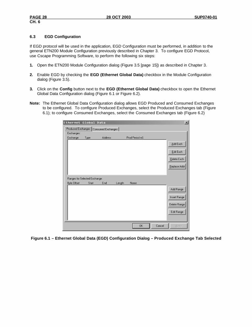
Global Data Configuration dialog (Figure 6.1 or Figure 6.2). Note: The Ethernet Global Data Configuration dialog allows EGD Produced and Consumed Exchanges
to be configured. To configure Produced Exchanges, select the Produced Exchanges tab (Figure 6.1); to configure Consumed Exchanges, select the Consumed Exchanges tab (Figure 6.2)
Figure 6.1 – Ethernet Global Data (EGD) Configuration Dialog – Produced Exchange Tab Selected

SUP0740-01 28 OCT 2003 PAGE 29 CH. 6
Figure 6.2 – Ethernet Global Data (EGD) Configuration Dialog – Consumed Exchange Tab Selected 4. Follow the steps in Section 6.4 to configure Produced Exchanges, as necessary for the application. 5. Follow the steps in Section 6.5 to configure Consumed Exchanges, as necessary for the application. 6. Click OK to accept the new EGD Configuration.

PAGE 30 28 OCT 2003 SUP0740-01 CH. 6
6.4 EGD Produced Exchange Configuration To configure EGD Produced Exchanges, open the Ethernet Global Data Configuration dialog (Figure 6.1) as described in Section 6.3, and select the Produced Exchanges tab, where: 1. In the upper window, one or more Produced Exchanges can be created (Section 6.4.1). 2. In the lower window, I/O Blocks can be defined for each Produced Exchange (Section 6.4.2). When creating a Produced Exchange, the application programmer selects an Exchange Number for it, determines whether the Exchange will be sent to a specific Consumer or to a Group of Consumers, chooses which Consumer or Group of Consumers will receive the Exchange, and sets how often the Exchange will be sent to the EGD network. When defining I/O Blocks for a Produced Exchange, the application programmer selects what type and how much information will be associated with the Exchange. For Produced Exchanges, there are two types of I/O Blocks to choose from: Data and Status. Table 6.2 shows these I/O Block Types along with their definitions:
Table 6.2 – Produced Exchange I/O Block Type Definitions Type Definition
Data Block Block of consecutive OCS registers to be sent periodically to the EGD network Status Block 16-bit OCS register to be written with the Produced Exchange’s Status Word
When defining Data Blocks for a Produced Exchange, the maximum total OCS register data the Exchange can send to the EGD network is 1400 bytes. This means that up to a total of 700 16-bit registers (%R, %AI, AQ, etc.), or 11,200 1-bit registers (%M, %T, %I, %Q, etc.), or a combination thereof can be defined for a Produced Exchange. Note: The ETN200 module allows a total of up to 256 Data Blocks to be defined for all Produced
Exchanges combined. This means that if 127 Produced Exchanges are configured, each can have an average of about 2 Data Blocks defined.
When a Status Block is defined for a Produced Exchange, exactly 2 bytes of register data are written with the Produced Exchange’s Status Word. See Section 6.7 for general information regarding EGD Status Words, and Section 6.7.1 for specific information regarding EGD Produced Exchange Status Words. Note: The ETN200 module maintains just one 16-bit status word for each Produced Exchange. For this
reason, there is never any need to define more than one Status Block for a given Produced Exchange.

SUP0740-01 28 OCT 2003 PAGE 31 CH. 6
6.4.1 Creating EGD Produced Exchanges To create EGD Produced Exchanges, perform the following six steps: 1. In the Ethernet Global Data Configuration dialog (Figure 6.1), click on the Add Exch button to open
the Add / Edit Produced Exchange dialog (Figure 6.3).
Figure 6.3 – Add / Edit Produced Exchange Dialog – IP Address Selected 2. Configure the Produced Exchange parameters as follows:
Exchange Number: Enter a number between 1 and 16,383, which will be used to identify the Exchange to be sent. IP Address Radio Button: Select this option if the Exchange will be sent to a specific Consumer. (This will cause the next edit box to be for entering IP Address, instead of Group ID.) Group ID Radio Button: Select this option if the Exchange will be sent to a Group of Consumers. (This will cause the next edit box to be for entering Group ID, instead of IP Address.) IP Address Edit Box: If the IP Address radio button was selected, enter the IP Address of the specific Consumer that will receive the Produced Exchange. Group ID Edit Box: If the Group ID radio button was selected, enter the Group ID number (1 to 32) of the Group of Consumers that will receive the Produced Exchange.
Production Period: Enter a number (in milliseconds) for how often the Produced Exchange will be sent to the EGD network.
3. Click OK to accept the new Produced Exchange configuration, which will be now be displayed in the
upper window of the Ethernet Global Data Configuration dialog (Figure 6.1). 4. To add another Produced Exchange to the list, click on the Add Exch button again. 5. To edit or delete a Produced Exchange, highlight it in the upper window of the Ethernet Global Data
Configuration dialog (Figure 6.1), and then click on the Edit Exch button or the Delete Exch button. 6. To quickly change the IP Address in multiple Produced Exchanges, click on the Replace Addr
button. This will open a dialog to allow the user to search and replace the IP Address parameter, in all Produced Exchanges simultaneously.

PAGE 32 28 OCT 2003 SUP0740-01 CH. 6
6.4.2 Defining EGD Produced Exchange I/O Blocks After creating a Produced Exchange (Section 6.4.1), one or more I/O Blocks should be defined for it. An I/O Block specifies what type and how much information will be associated with the Produced Exchange. To define I/O Blocks for a Produced Exchange, perform the following six steps: 1. In the upper window of the Ethernet Global Data Configuration dialog (Figure 6.1), highlight one of the
Produced Exchanges, and then click the Add Range button to open the Add I/O Range to Exchange dialog (Figure 6.4).
Figure 6.4 – Add I/O Range to Exchange Dialog 2. Configure the I/O Block parameters as follows:
Type: Select Data Type to define a block of OCS registers, which the Produced Exchange will periodically read and send to the EGD network. Select Status Type to define a 16-bit OCS register, which will be written with the Produced Exchange’s Status Word. Address: Enter an OCS Register reference (such as %R1000), for the first OCS register, in a block of OCS registers, that will be periodically read and sent (Data Type), or for a 16-bit OCS register that will be written with status information (Status Type). Number of Registers: If Data Type was selected, enter the number of registers to be periodically read and sent. If Status Type was selected, this edit box changes to Number of Bytes, and always has a fixed value of 2.
3. Click OK to accept the Produced Exchange’s new I/O Block, which will be now be displayed in the lower window of the Ethernet Global Data Configuration dialog (Figure 6.1).
Note: The OCS registers, specified in Data Block definitions, are sent to the EGD network in top-to-
bottom order, as they appear in the lower window of the Ethernet Global Data Configuration dialog (Figure 6.1).
4. To add another I/O Block, click the Add Range button again and repeat steps 2 and 3. The new I/O
Block will appear at the end of the list. 5. To insert an I/O Block into the middle of the list, highlight one of the I/O Block items in the list and
then click on the Insert Range button. In this case, the new I/O Block will be inserted just before the highlighted I/O Block.
6. To edit or delete an I/O Block in the list, highlight it and then click on the Edit Range or Delete Range
button.

SUP0740-01 28 OCT 2003 PAGE 33 CH. 6
6.5 EGD Consumed Exchange Configuration To configure EGD Consumed Exchanges, open the Ethernet Global Data Configuration dialog (Figure 6.2) as described in Section 6.3, and select the Consumed Exchanges tab, where: 1. In the upper window, one or more Consumed Exchanges can be created (Section 6.5.1). 2. In the lower window, I/O Blocks can be defined for each Consumed Exchange (Section 6.5.2). When creating a Consumed Exchange, the application programmer selects an Exchange Number for it, determines whether to receive the Exchange as a single Consumer or as a member of a Group of Consumers, chooses which Producer to receive the Exchange from, and sets how often to expect the Exchange to be received. When defining I/O Blocks for a Consumed Exchange, the application programmer selects what type and how much information will be associated with the Exchange. For Consumed Exchanges, there are five types of I/O Blocks to choose from: Data, Status, Timestamp, OCS Timestamp, and Filler. Table 6.3 shows these I/O Block Types along with their definitions:
Table 6.3 – Consumed Exchange I/O Block Type Definitions Type Definition
Data Block Block of consecutive OCS registers to be written with received data Status Block 16-bit OCS register to be written with the Consumed Exchange’s status word
Timestamp Block 8-byte binary timestamp indicating when the Producer sampled the data OCS Timestamp Block 14-byte OCS-format timestamp indicating when the Producer sampled the data
Filler Block Specifies a block of received data to ignore (skips unwanted data) When defining Data Blocks for a Consumed Exchange, the maximum total OCS register data the Exchange can receive from the EGD network is 1400 bytes. This means that up to a total of 700 16-bit registers (%R, %AI, AQ, etc.), or 11,200 1-bit registers (%M, %T, %I, %Q, etc.), or a combination thereof can be defined for a Consumed Exchange. Note: The ETN200 module allows a total of up to 256 Data Blocks to be defined for all Consumed
Exchanges combined. This means that if 127 Consumed Exchanges are configured, each can have an average of about 2 Data Blocks defined.
When a Status Block is defined for a Consumed Exchange, exactly 2 bytes of register data are written with the Consumed Exchange’s Status Word. See Section 6.7 for general information regarding EGD Status Words, and Section 6.7.2 for specific information regarding EGD Consumed Exchange Status Words. For a Timestamp Block, exactly 8 bytes of register data will be written with two 32-bit binary timestamp values, containing the number of seconds and nanoseconds since January 1, 1970. For an OCS Timestamp Block, exactly 14 bytes of register data will be written with a 7-word OCS-format timestamp, consisting of second, minute, hour, day, month, year and millisecond words. This OCS Timestamp can be displayed on the OCS screen, can be loaded into the OCS time-of-day clock, and can be easily processed by ladder logic. Note: The binary Timestamp Block is rarely used, and there is never any need to define more than one
Status Block or OCS Timestamp Block for a given Consumed Exchange. A Filler Block is used to skip unwanted data sent by the Producer. For example, if the Producer sends 40 data bytes in an Exchange, and the Consumer only needs the first and last 10 bytes, a Filler Block would be defined, in the appropriate slot in the list, to skip the middle 20 bytes of data.
PAGE 34 28 OCT 2003 SUP0740-01 CH. 6
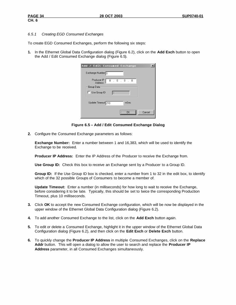
6.5.1 Creating EGD Consumed Exchanges To create EGD Consumed Exchanges, perform the following six steps: 1. In the Ethernet Global Data Configuration dialog (Figure 6.2), click on the Add Exch button to open
the Add / Edit Consumed Exchange dialog (Figure 6.5).
Figure 6.5 – Add / Edit Consumed Exchange Dialog 2. Configure the Consumed Exchange parameters as follows:
Exchange Number: Enter a number between 1 and 16,383, which will be used to identify the Exchange to be received. Producer IP Address: Enter the IP Address of the Producer to receive the Exchange from. Use Group ID: Check this box to receive an Exchange sent by a Producer to a Group ID. Group ID: If the Use Group ID box is checked, enter a number from 1 to 32 in the edit box, to identify which of the 32 possible Groups of Consumers to become a member of. Update Timeout: Enter a number (in milliseconds) for how long to wait to receive the Exchange, before considering it to be late. Typically, this should be set to twice the corresponding Production Timeout, plus 10 milliseconds.
3. Click OK to accept the new Consumed Exchange configuration, which will be now be displayed in the
upper window of the Ethernet Global Data Configuration dialog (Figure 6.2). 4. To add another Consumed Exchange to the list, click on the Add Exch button again. 5. To edit or delete a Consumed Exchange, highlight it in the upper window of the Ethernet Global Data
Configuration dialog (Figure 6.2), and then click on the Edit Exch or Delete Exch button. 6. To quickly change the Producer IP Address in multiple Consumed Exchanges, click on the Replace
Addr button. This will open a dialog to allow the user to search and replace the Producer IP Address parameter, in all Consumed Exchanges simultaneously.

SUP0740-01 28 OCT 2003 PAGE 35 CH. 6
6.5.2 Defining EGD Consumed Exchange I/O Blocks After creating a Consumed Exchange (Section 6.5.1), one or more I/O Blocks should be defined for it. An I/O Block specifies what type and how much information will be associated with the Consumed Exchange. To define I/O Blocks for a Consumed Exchange, perform the following six steps: 1. In the upper window of the Ethernet Global Data Configuration dialog (Figure 6.2), highlight one of the
Consumed Exchanges, and then click the Add Range button to open the Add I/O Range to Exchange dialog (Figure 6.4).
2. Configure the I/O Block parameters as follows:
Type: Select Data Type to define a block of OCS registers, which the Consumed Exchange will write with received data. Select Status Type to define a 16-bit OCS register, which will be written with the Consumed Exchange’s Status Word. Select OCS Timestamp Type to define a 14-byte OCS register block to write with the received data’s OCS-format timestamp. Select Filler Type, to skip unwanted received data. Address: Enter an OCS Register reference (such as %R2000), for the first OCS register, in a block of OCS registers, that will be written with received data (Data Type), or for a 16-bit OCS register that will be written with status information (Status Type), or for the first OCS register in a block of OCS registers that will be written with the 14-byte timestamp (OCS Timestamp Type). For Filler Type, the Address edit box is not used. Number of Registers: If Data Type was selected, enter the number of registers to be written with received data. Otherwise, this edit box changes to Number of Bytes, and has a fixed value of 2 for Status Type or 14 for OCS Timestamp Type. For Filler Type, enter the number of unwanted received data bytes to skip.
3. Click OK to accept the Consumed Exchange’s new I/O Block, which will be now be displayed in the lower window of the Ethernet Global Data Configuration dialog (Figure 6.2).
Note: The OCS registers, specified in Data Block definitions, are filled with received data in top-to-
bottom order, as they appear in the lower window of the Ethernet Global Data Configuration dialog (Figure 6.2). In this respect, Filler Blocks are placeholders for Data Blocks and can be thought of as Data Blocks whose received data bytes are discarded.
4. To add another I/O Block, click on the Add Range button again and repeat steps 2 and 3. The new
I/O Block will appear at the end of the list. 5. To insert an I/O Block into the middle of the list, highlight one of the I/O Block items in the list and
then click on the Insert Range button. In this case, the new I/O Block will be inserted just before the highlighted I/O Block.
6. To edit or delete an I/O Block in the list, highlight it and then click on the Edit Range or Delete Range
button.

PAGE 36 28 OCT 2003 SUP0740-01 CH. 6
6.6 EGD Operation Unlike other protocols, EGD protocol stops completely when the OCS (or RCS) is not in RUN mode. In this case, EGD Produced Exchanges are not transmitted, and all received Consumed Exchanges are ignored. As soon as an OCS (or RCS), containing a configured ETN200 module, is placed into RUN mode, it will start exchanging EGD messages with other EGD devices on the network, as follows:
1. The ETN200 will transmit each configured Produced Exchange (see Section 6.4) periodically, according to its Production Period (in milliseconds).
2. The ETN200 will expect to receive each configured Consumed Exchange (see Section 6.5) at least as often as its Update Timeout (in milliseconds).
3. The ETN200 will maintain a Status Word for each Produced and Consumed Exchange, as described in Section 6.7, and will report these Status Words in OCS (or RCS) registers, if configured to do so (see Sections 6.4 and 6.5).
6.7 EGD Status Words EGD Status Words allow an Ethernet Global Data user to obtain the operating status of each EGD Exchange. The set of EGD Status Word values, implemented in the ETN200 module, is a subset of the ones used in GE Fanuc EGD devices. This is due to the fact that the ETN200 module does not support dynamically defined (at run time) EGD Exchanges. Please note that both Produced and Consumed Exchange Status Words are written to local OCS registers. This is the only case where a Produced Exchange can be configured to write to a local register. The Status Word for a Produced Exchange is updated each time the Exchange’s Production Period expires. The Status Word for a Consumed Exchange is updated when new data arrives for consumption or when the Exchange’s Update Timeout expires. In normal operation, each EGD Exchange’s Status Word will always be 1 (OK), implying that new data was successfully Produced or Consumed. If the application needs to be notified when a data transfer has occurred on a given Exchange, the ladder program should clear the Exchange’s Status Word register to 0 (IDLE) each time a non-zero event is detected. 6.7.1 EGD Produced Exchange Status Words The Status Word for an EGD Produced Exchange can take on the following values: 0 IDLE - No new status event has occurred. The ETN200 module initializes all Status Words to 0,
only at power-up and each time the OCS enters RUN mode. Subsequently, the OCS application ladder program can write the value 0 to the Status Word, as an aid in knowing when Ethernet Global Data production occurs (see Status Word 1).
1 OK - Data Produced. New EGD network data has been transmitted. A transition to 1 indicates
production of data occurred since the last OCS ladder scan. 2 NO LINK - The Ethernet link was down when EGD data production was attempted. This will
occur, for example, if the Ethernet cable is unplugged from the OCS.

SUP0740-01 28 OCT 2003 PAGE 37 CH. 6
6.7.2 EGD Consumed Exchange Status Words The Status Word for an EGD Consumed Exchange can take on the following values: 0 IDLE - No new status event has occurred. The ETN200 module initializes all Status Words to 0,
only at power-up and each time the OCS enters RUN mode. Subsequently, the OCS application ladder program can write the value 0 to the Status Word, as an aid in knowing when Ethernet Global Data consumption occurs (see Status Words 1 and 7).
1 OK - Data Consumed. New EGD network data has been received as expected (before the
configured Update Timeout expired). A transition to 1 (or to 7) indicates consumption of data occurred since the last OCS ladder scan.
2 NO LINK - The Ethernet link was down when EGD data consumption was expected. This will
occur, for example, if the Ethernet cable is unplugged from the OCS. 4 NO SYNC - SNTP Error. The Ethernet Interface in the device producing the exchange is
configured for network time synchronization (Network Time Sync parameter is set to SNTP), but is not synchronized to an SNTP server. Therefore, the timestamp associated with this data is not synchronized to the network. Note: This error condition is considered the least important of all the error codes in this section. If another error condition exists, its status code will appear in the Status Word.
6 OVERDUE - Data Refresh Error. The Update Timeout has expired without receiving the
expected data. Some possible causes for this error are: (1) the Producer has stopped producing the data, (2) the Consumed Exchange’s configured Producer IP Address and/or Group ID do not exactly match those of the corresponding Produced Exchange, (3) or the Consumed Exchange’s configured Update Timeout is too short (it should normally be twice the producer’s Production Period, plus 10 milliseconds).
7 TARDY - Data Consumed Late. New EGD network data has been received, but it is later than
expected (after the configured Update Timeout expired). A transition to 7 (or to 1) indicates consumption of data occurred since the last OCS ladder scan. The most probable cause for this error is that the Consumed Exchange’s configured Update Timeout is too short (it should normally be twice the producer’s Production Period, plus 10 milliseconds).

PAGE 38 28 OCT 2003 SUP0740-01 CH. 6
6.8 EGD Example 1 Figure 6.6 shows a simple example, in which Node 1 uses Exchange 1 to transmit 10 words of data to Node 2 every 100 mS, and Node 2 uses Exchange 2 to transmit 5 words of data to Node 1 every 200 mS.
Figure 6.6 – EGD Example 1 Exchange Interaction 6.8.1 EGD Example 1 – Configuring Node 1 To configure Node 1 for EGD Example 1, as shown in Figure 6.6, perform the following six steps: 1. On the main Cscape screen, select New on the File menu to start a new user program. Then open
the ETN200 Module Configuration dialog (Chapter 3, Figure 3.5 [page 15]), and fill in the parameters for Node 1, as shown in Figure 6.7 below.
In this example, Node 1 will have a Static IP Address (Section 3.2.1 [page 17]), and the %R1, %R2 and %R3 registers will be used to report the ETN200 Module’s status, firmware version, and IP Address (step 5 in Section 3.1 [page 15]). Note that since an IP Address is 32-bits long, Node 1’s IP Address (192.168.0.1) will actually be written into %R3 and %R4.
Figure 6.7 - ETN200 Module Configuration - Node 1
Node 1
IP Address 192.168.0.1
Node 2
IP Address 192.168.0.2
Exchange 1: Produced by Node 1; Consumed by Node 2; 192.168.0.1 sends 10 words of data every 100 mS to 192.168.0.2
Exchange 2: Produced by Node 2; Consumed by Node 1; 192.168.0.2 sends 5 words of data every 200 mS to 192.168.0.1

SUP0740-01 28 OCT 2003 PAGE 39 CH. 6
2. Click on the Config button next to the EGD (Ethernet Global Data) checkbox to open the Ethernet
Global Data Configuration dialog (Figure 6.1 [page 28]) and click on the Add Exch button to create a Produced Exchange. Then, fill in the parameters for Node 1, as shown in Figure 6.8 below, and click OK.
In this example, Node 1 will transmit Exchange 1 to a specific Consumer (Node 2), instead of to a Group of Consumers. Also, the Production Period is set to 100, which will cause Node 1 to transmit Exchange 1 every 100 mS.
Figure 6.8 – Creating Produced Exchange 1 - Node 1 3. Click on the Add Range button, in the EGD Configuration dialog, to define a Data Block for Produced
Exchange 1. Then fill in the parameters, as shown in Figure 6.9 below, and click OK.
In this example, Node 1 will use Exchange 1, to transmit 10 words of data taken from %R100 through %R109.
Figure 6.9 – Produced Exchange 1 Data Block Definition – Node 1

PAGE 40 28 OCT 2003 SUP0740-01 CH. 6
At this point, the Produced Exchanges tab in the EGD Configuration dialog should be as shown in Figure 6.10.
Figure 6.10 – Configured Produced Exchange 1 - Node 1 4. Now that Exchange 1 has been configured as a Produced Exchange for Node 1, it is time to configure
Exchange 2 as a Consumed Exchange for Node 1. To do this, first select the Consumed Exchanges tab (Figure 6.2 [page 29) and click on the Add Exch button to create a Consumed Exchange. Then fill in the parameters, as shown in Figure 6.11 below, and click OK.
In this example, Node 1 will be the only Consumer to receive Exchange 2 from Node 2 and will not be a member of a Group of Consumers. Also, the Update Timeout is set to 410, which means Node 1 will expect to receive Exchange 2 from Node 2 at least every 410 mS. Note this is twice the time, plus 10 mS, that Node 2 will be configured to transmit Exchange 2 as recommended in Table 6.1.
Figure 6.11 - Creating Consumed Exchange 2 - Node 1

SUP0740-01 28 OCT 2003 PAGE 41 CH. 6
5. Click on the Add Range button, in the EGD Configuration dialog, to define a Data Block for
Consumed Exchange 2. Then fill in the parameters, as shown in Figure 6.12 below, and click OK. In this example, Node 1 will use Exchange 2, to receive 5 data words into %R200 through %R204.
Figure 6.12 – Consumed Exchange 2 Data Block Definition – Node 1
At this point, the Consumed Exchanges tab in the EGD Configuration dialog should be as shown in Figure 6.13.
Figure 6.13 – Configured Consumed Exchange 2 - Node 1 6. Node 1 configuration is now complete. Click OK, save the user program using an appropriate
filename, such as EGD Node 1.csp, and then continue with Section 6.8.2 to perform Node 2 configuration.

PAGE 42 28 OCT 2003 SUP0740-01 CH. 6
6.8.2 EGD Example 1 – Configuring Node 2 To configure Node 2 for EGD Example 1, as shown in Figure 6.6, perform the following six steps: 1. On the main Cscape screen, select New on the File menu to start a new user program. Then open
the ETN200 Module Configuration dialog (Chapter 3, Figure 3.5 [page 15]), and fill in the parameters for Node 2, as shown in Figure 6.14 below.
In this example, Node 2 will have a Static IP Address (Section 3.2.1 [page 17]), and the %R1, %R2 and %R3 registers will be used to report the ETN200 Module’s status, firmware version, and IP Address (step 5 in Section 3.1 [page 15]). Note that since an IP Address is 32-bits long, Node 2’s IP Address (192.168.0.2) will actually be written into %R3 and %R4.
Figure 6.14 - ETN200 Module Configuration - Node 2
SUP0740-01 28 OCT 2003 PAGE 43 CH. 6
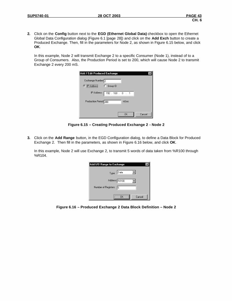
2. Click on the Config button next to the EGD (Ethernet Global Data) checkbox to open the Ethernet
Global Data Configuration dialog (Figure 6.1 [page 28]) and click on the Add Exch button to create a Produced Exchange. Then, fill in the parameters for Node 2, as shown in Figure 6.15 below, and click OK.
In this example, Node 2 will transmit Exchange 2 to a specific Consumer (Node 1), instead of to a Group of Consumers. Also, the Production Period is set to 200, which will cause Node 2 to transmit Exchange 2 every 200 mS.
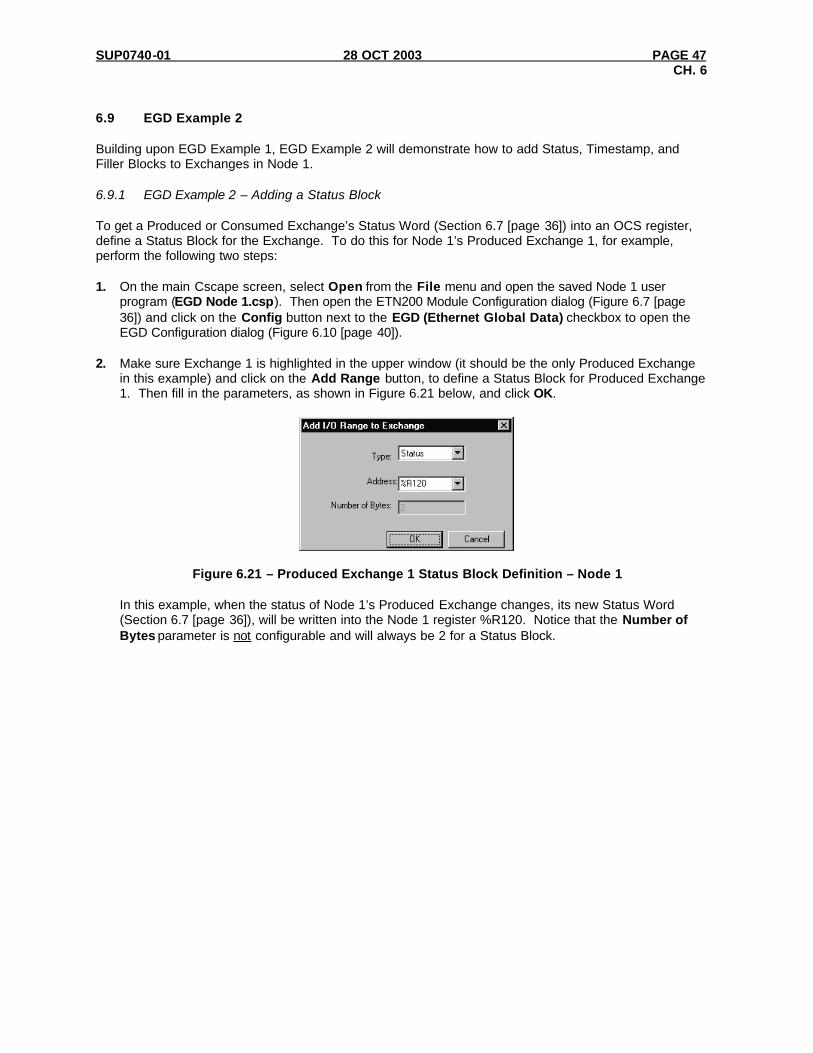
Figure 6.15 – Creating Produced Exchange 2 - Node 2 3. Click on the Add Range button, in the EGD Configuration dialog, to define a Data Block for Produced
Exchange 2. Then fill in the parameters, as shown in Figure 6.16 below, and click OK.
In this example, Node 2 will use Exchange 2, to transmit 5 words of data taken from %R100 through %R104.
Figure 6.16 – Produced Exchange 2 Data Block Definition – Node 2

PAGE 44 28 OCT 2003 SUP0740-01 CH. 6
At this point, the Produced Exchanges tab in the EGD Configuration dialog should be as shown in Figure 6.17.
Figure 6.17 – Configured Produced Exchange 2 - Node 2 4. Now that Exchange 2 has been configured as a Produced Exchange for Node 2, it is time to configure
Exchange 1 as a Consumed Exchange for Node 2. To do this, first select the Consumed Exchanges tab (Figure 6.2 [page 29]) and click on the Add Exch button to create a Consumed Exchange. Then fill in the parameters, as shown in Figure 6.18 below, and click OK.
In this example, Node 2 will be the only Consumer to receive Exchange 1 from Node 1, and will not be a member of a Group of Consumers. Also, the Update Timeout is set to 210, which means Node 2 will expect to receive Exchange 1 from Node 1 at least every 210 mS. Note this is twice the time, plus 10 mS, that Node 1 was configured to transmit Exchange 1, as recommended in Table 6.1.
Figure 6.18 - Creating Consumed Exchange 1 - Node 2

SUP0740-01 28 OCT 2003 PAGE 45 CH. 6
5. Click on the Add Range button, in the EGD Configuration dialog, to define a Data Block for
Consumed Exchange 1. Then fill in the parameters, as shown in Figure 6.19 below, and click OK. In this example, Node 2 will use Exchange 1, to receive 10 data words into %R200 through %R209.
Figure 6.19 – Consumed Exchange 1 Data Block Definition – Node 2
At this point, the Consumed Exchanges tab in the EGD Configuration dialog should be as shown in Figure 6.20.
Figure 6.20 – Configured Consumed Exchange 1 - Node 2 6. Node 2 configuration is now complete. Click OK, save the user program using an appropriate
filename, such as EGD Node 2.csp, and then continue with Section 6.8.3, to start EGD communication between Node 1 and Node 2.

PAGE 46 28 OCT 2003 SUP0740-01 CH. 6
6.8.3 EGD Example 1 – Starting EGD Communication between Node 1 and Node 2 Now that both Node 1 and Node 2 have been configured for EGD Example 1 (Figure 6.6), start them communicating as follows: 1. Open the saved Node 1 user program (EGD Node 1.csp), and download it to Node 1. 2. Open the saved Node 2 user program (EGD Node 2.csp), and download it to Node 2. 3. Connect both Node 1 and Node 2 to an Ethernet network and put them both in RUN mode. At this point, Node 1 and Node 2 should be exchanging EGD data as follows:
1. Every 100 mS, Node 1 will read its %R100 through %R109 registers and send them via Exchange 1 to be received by Node 2 into Node 2’s %R200 through %R209 registers.
2. Every 200 mS, Node 2 will read its %R100 through %R104 registers and send them via
Exchange 2 to be received by Node 1 into Node 1’s %R200 through %R204 registers.
SUP0740-01 28 OCT 2003 PAGE 47 CH. 6
6.9 EGD Example 2 Building upon EGD Example 1, EGD Example 2 will demonstrate how to add Status, Timestamp, and Filler Blocks to Exchanges in Node 1. 6.9.1 EGD Example 2 – Adding a Status Block To get a Produced or Consumed Exchange’s Status Word (Section 6.7 [page 36]) into an OCS register, define a Status Block for the Exchange. To do this for Node 1’s Produced Exchange 1, for example, perform the following two steps: 1. On the main Cscape screen, select Open from the File menu and open the saved Node 1 user
program (EGD Node 1.csp). Then open the ETN200 Module Configuration dialog (Figure 6.7 [page 36]) and click on the Config button next to the EGD (Ethernet Global Data) checkbox to open the EGD Configuration dialog (Figure 6.10 [page 40]).
2. Make sure Exchange 1 is highlighted in the upper window (it should be the only Produced Exchange
in this example) and click on the Add Range button, to define a Status Block for Produced Exchange 1. Then fill in the parameters, as shown in Figure 6.21 below, and click OK.
Figure 6.21 – Produced Exchange 1 Status Block Definition – Node 1
In this example, when the status of Node 1’s Produced Exchange changes, its new Status Word (Section 6.7 [page 36]), will be written into the Node 1 register %R120. Notice that the Number of Bytes parameter is not configurable and will always be 2 for a Status Block.

PAGE 48 28 OCT 2003 SUP0740-01 CH. 6
At this point, the Produced Exchanges tab in the EGD Configuration dialog should be as shown in Figure 6.22.
Figure 6.22 – Produced Exchange 1 with Status Block – Node 1 6.9.2 EGD Example 2 – Adding an OCS Timestamp Block In EGD protocol, a timestamp is sent with every Produced Exchange, indicating when the Producer sampled the data being sent. For a Consumer of the Exchange to get this information into an OCS register, define an OCS Timestamp Block for the Consumed Exchange. To do this for Node 1’s Consumed Exchange 2, for example, perform the following 2 steps: 1. In the EGD Configuration dialog (Figure 6.22), select the Consumed Exchanges tab. 2. Make sure Exchange 2 is highlighted in the upper window (it should be the only Consumed Exchange
in this example) and click on the Add Range button, to define an OCS Timestamp Block for Consumed Exchange 2. Then fill in the parameters, as shown in Figure 6.23 below, and click OK.
Figure 6.23 – Consumed Exchange 2 OCS Timestamp Block Definition – Node 1

SUP0740-01 28 OCT 2003 PAGE 49 CH. 6
In this example, when Node 1 receives Consumed Exchange 2 from Node 2, its timestamp will be converted into a 14-byte OCS-format timestamp, and will be written into the Node 1 registers %R220 through %R226. Notice that the Number of Bytes parameter is not configurable and will always be 14 for an OCS Timestamp Block.
At this point, the Consumed Exchanges tab in the EGD Configuration dialog should be as shown in Figure 6.24.
Figure 6.24 – Consumed Exchange 2 with Data and OCS Timestamp Blocks – Node 1 6.9.3 EGD Example 2 – Adding a Filler Block Sometimes a Consumer does not need all of the data sent by a Producer in an Exchange. In this case, the Consumed Exchange’s Data Block should be defined to receive fewer registers than will be sent by the Producer of the Exchange. However, if the partial data needed by the Consumer is not at the beginning of the data received in an Exchange, there must be some way to skip (ignore) the extra data. For this reason, the ETN200 supports Filler Blocks for Consumed Exchanges. For example, if Node 1 only needs the 5th word of the 5 data words sent by Node 2 in Exchange 2, skip the 1st four data words by defining a Filler Block for Node 1’s Consumed Exchange 2. To do this, perform the following 2 steps: 1. Referring the Figure 6.24, highlight Exchange 2 in the upper window, highlight the first entry in the
lower window, and click on the Edit Range button. Change the Data Block into a Filler Block, by editing the parameters as shown in Figure 6.25a below, and then click OK.

PAGE 50 28 OCT 2003 SUP0740-01 CH. 6
2. With Exchange 2 still highlighted in the upper window, click on the Add Range button, to define a
new Data Block for Consumed Exchange 2. Then fill in the parameters, as shown in Figure 6.25b below, and click OK.
a. b.
Figure 6.25 – Consumed Exchange 2 Filler and Data Block Definitions – Node 1
In this example, the first 4 data words (8 bytes) received by Node 1 in Exchange 2 will be skipped, and the 5th data word will be written to Node 1 register %R200. At this point, the Consumed Exchanges tab in the EGD Configuration dialog should be as shown in Figure 6.26. Note: OCS Timestamp and Status Blocks contain overhead information, and are not considered to
be part of an Exchange’s data. Therefore the position of the OCS Timestamp Block in the lower window of Figure 6.26, does not affect the sequence of the data received in the Exchange. Only Data Blocks and Filler Blocks are position-sensitive.
.
Figure 6.26 - Consumed Exchange 2 with Filler, OCS Timestamp and Data Blocks - Node 1
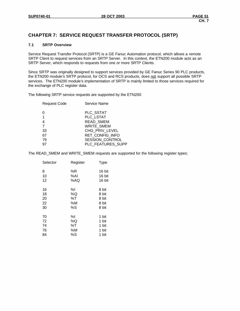
SUP0740-01 28 OCT 2003 PAGE 51 CH. 7
CHAPTER 7: SERVICE REQUEST TRANSFER PROTOCOL (SRTP) 7.1 SRTP Overview Service Request Transfer Protocol (SRTP) is a GE Fanuc Automation protocol, which allows a remote SRTP Client to request services from an SRTP Server. In this context, the ETN200 module acts as an SRTP Server, which responds to requests from one or more SRTP Clients. Since SRTP was originally designed to support services provided by GE Fanuc Series 90 PLC products, the ETN200 module’s SRTP protocol, for OCS and RCS products, does not support all possible SRTP services. The ETN200 module’s implementation of SRTP is mainly limited to those services required for the exchange of PLC register data. The following SRTP service requests are supported by the ETN200:
Request Code Service Name 0 PLC_SSTAT 1 PLC_LSTAT 4 READ_SMEM 7 WRITE_SMEM 33 CHG_PRIV_LEVEL 67 RET_CONFIG_INFO 79 SESSION_CONTROL 97 PLC_FEATURES_SUPP
The READ_SMEM and WRITE_SMEM requests are supported for the following register types:
Selector Register Type 8 %R 16 bit 10 %AI 16 bit 12 %AQ 16 bit 16 %I 8 bit 18 %Q 8 bit 20 %T 8 bit 22 %M 8 bit 30 %S 8 bit 70 %I 1 bit 72 %Q 1 bit 74 %T 1 bit 76 %M 1 bit 84 %S 1 bit
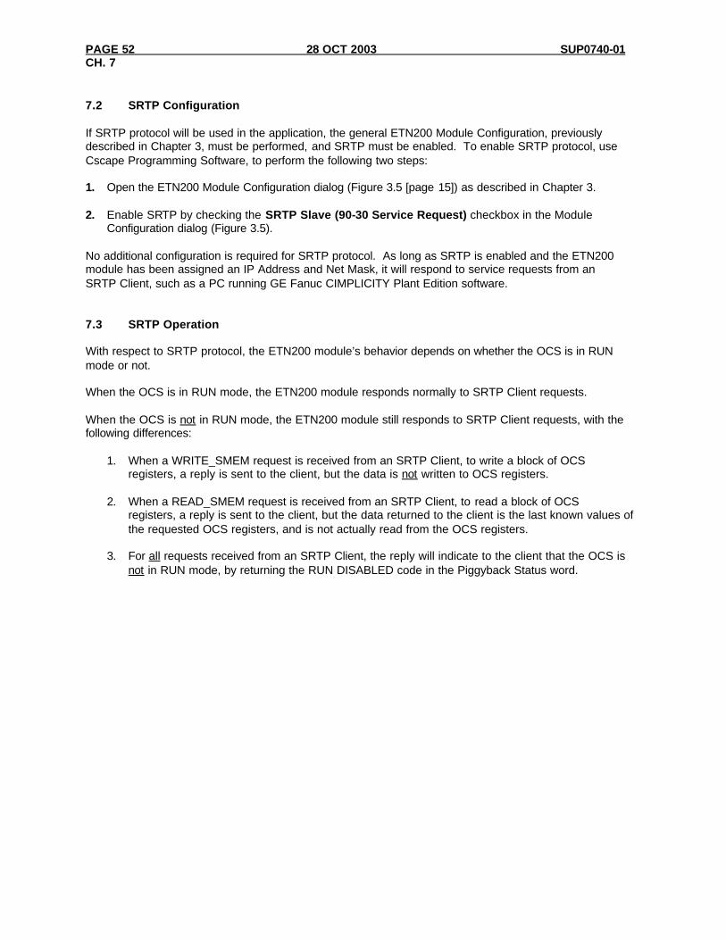
PAGE 52 28 OCT 2003 SUP0740-01 CH. 7
7.2 SRTP Configuration If SRTP protocol will be used in the application, the general ETN200 Module Configuration, previously described in Chapter 3, must be performed, and SRTP must be enabled. To enable SRTP protocol, use Cscape Programming Software, to perform the following two steps: 1. Open the ETN200 Module Configuration dialog (Figure 3.5 [page 15]) as described in Chapter 3. 2. Enable SRTP by checking the SRTP Slave (90-30 Service Request) checkbox in the Module
Configuration dialog (Figure 3.5). No additional configuration is required for SRTP protocol. As long as SRTP is enabled and the ETN200 module has been assigned an IP Address and Net Mask, it will respond to service requests from an SRTP Client, such as a PC running GE Fanuc CIMPLICITY Plant Edition software. 7.3 SRTP Operation With respect to SRTP protocol, the ETN200 module’s behavior depends on whether the OCS is in RUN mode or not. When the OCS is in RUN mode, the ETN200 module responds normally to SRTP Client requests. When the OCS is not in RUN mode, the ETN200 module still responds to SRTP Client requests, with the following differences:
1. When a WRITE_SMEM request is received from an SRTP Client, to write a block of OCS registers, a reply is sent to the client, but the data is not written to OCS registers.
2. When a READ_SMEM request is received from an SRTP Client, to read a block of OCS
registers, a reply is sent to the client, but the data returned to the client is the last known values of the requested OCS registers, and is not actually read from the OCS registers.
3. For all requests received from an SRTP Client, the reply will indicate to the client that the OCS is
not in RUN mode, by returning the RUN DISABLED code in the Piggyback Status word.
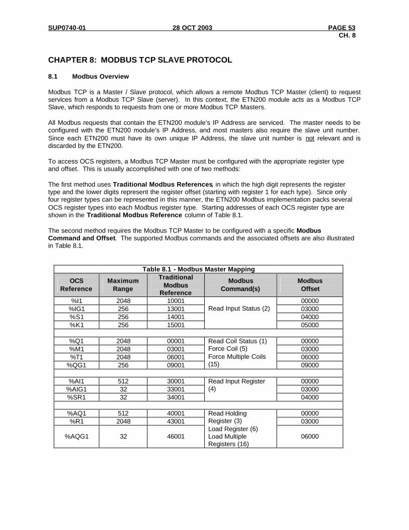
SUP0740-01 28 OCT 2003 PAGE 53 CH. 8
CHAPTER 8: MODBUS TCP SLAVE PROTOCOL 8.1 Modbus Overview Modbus TCP is a Master / Slave protocol, which allows a remote Modbus TCP Master (client) to request services from a Modbus TCP Slave (server). In this context, the ETN200 module acts as a Modbus TCP Slave, which responds to requests from one or more Modbus TCP Masters. All Modbus requests that contain the ETN200 module’s IP Address are serviced. The master needs to be configured with the ETN200 module’s IP Address, and most masters also require the slave unit number. Since each ETN200 must have its own unique IP Address, the slave unit number is not relevant and is discarded by the ETN200. To access OCS registers, a Modbus TCP Master must be configured with the appropriate register type and offset. This is usually accomplished with one of two methods: The first method uses Traditional Modbus References, in which the high digit represents the register type and the lower digits represent the register offset (starting with register 1 for each type). Since only four register types can be represented in this manner, the ETN200 Modbus implementation packs several OCS register types into each Modbus register type. Starting addresses of each OCS register type are shown in the Traditional Modbus Reference column of Table 8.1. The second method requires the Modbus TCP Master to be configured with a specific Modbus Command and Offset. The supported Modbus commands and the associated offsets are also illustrated in Table 8.1.
Table 8.1 - Modbus Master Mapping
OCS Reference
Maximum Range
Traditional Modbus
Reference
Modbus Command(s)
Modbus Offset
%I1 2048 10001 00000 %IG1 256 13001 03000 %S1 256 14001 04000 %K1 256 15001
Read Input Status (2)
05000
%Q1 2048 00001 00000 %M1 2048 03001 03000 %T1 2048 06001 06000
%QG1 256 09001
Read Coil Status (1) Force Coil (5) Force Multiple Coils (15) 09000
%AI1 512 30001 00000
%AIG1 32 33001 03000 %SR1 32 34001
Read Input Register (4) 04000
%AQ1 512 40001 00000 %R1 2048 43001 03000
%AQG1 32 46001
Read Holding Register (3) Load Register (6) Load Multiple Registers (16)
06000
PAGE 54 28 OCT 2003 SUP0740-01 CH. 8
8.2 Modbus Configuration If Modbus TCP Slave protocol will be used in the application, the general ETN200 Module Configuration, previously described in Chapter 3, must be performed, and Modbus must be enabled. To enable Modbus protocol, use Cscape Programming Software, to perform the following two steps: 1. Open the ETN200 Module Configuration dialog (Figure 3.5 [page 15]), as described in Chapter 3. 2. Enable Modbus by checking the Modbus TCP Slave checkbox in the Module Configuration dialog
(Figure 3.5). No additional configuration is required for Modbus protocol. As long as Modbus is enabled and the ETN200 module has been assigned an IP Address and Net Mask, it will respond to service requests from a Modbus TCP Master (client), such as a PC running GE Fanuc CIMPLICITY Plant Edition software. 8.3 Modbus Operation With respect to Modbus TCP Slave protocol, the ETN200 module’s behavior depends on whether the OCS is in RUN mode or not. When the OCS is in RUN mode, the ETN200 module responds normally to Modbus TCP Master requests. When the OCS is not in RUN mode, the ETN200 module still responds to Modbus TCP Master requests, with the following differences:
1. When a request is received from a Modbus TCP Master to write a block of OCS registers, a reply is sent to the Master, but the data is not written to OCS registers.
2. When a request is received from a Modbus TCP Master, to read a block of OCS registers, a reply
is sent to the Master, but the data returned to the Master is all zeroes. 3. A Modbus TCP Master can determine if the OCS is RUN mode in either of the following two
ways:
a. By reading the OCS Always On register (%S7), which is 1 if the OCS is in RUN mode and 0 if the OCS is not in RUN mode (because of item 2 above).
b. By issuing a Read Exception Status request, which returns an Exception Status of 0 if the
OCS is in RUN Mode or 1 if the OCS is not in RUN mode.

SUP0740-01 28 OCT 2003 PAGE 55 INDEX
INDEX
C
Configuration CsCAN ........................................................................ 19 EGD ............................................................................. 28 EGD Consumed Exchange ...................................... 33 EGD Produced Exchange......................................... 30 ETN200....................................................................... 13 General ........................................................................ 13 ICMP........................................................................... 25 Modbus........................................................................ 54 SRTP............................................................................ 52
Consumed Exchanges ................................................... 34 CsCAN
Configuration ............................................................. 19 Downloading Precautions........................................ 20 Operation..................................................................... 20 Overview..................................................................... 19 Prevent Losing Communication.............................. 21 Recover from Lost Communication....................... 21 Security........................................................................ 22
D
Default Gateway ............................................................ 16
E
EGD Configuration ............................................................. 28 Consumed Exchange Configuration....................... 33 Consumed Exchange I/O Block Definitions......... 33 Consumed Exchange Status Words........................ 37 Creating Consumed Exchanges............................... 34 Creating Produced Exchanges................................. 31 Defining Consumed Exchange I/O Blocks ........... 35 Defining Produced Exchange I/O Blocks ............. 32 Multicast IP Addressing........................................... 12 Operation..................................................................... 36 Overview..................................................................... 27 Produced Exchange Configuration......................... 30 Produced Exchange Status Words.......................... 36 Status Words.............................................................. 36 Terminology............................................................... 27 Unicast IP Addressing.............................................. 12
Ethernet Global Data Protocol (EGD) ....................... 27
I
ICMP
Configuration ............................................................. 25 Operation..................................................................... 26 Overview..................................................................... 25
Internal ETN200 ............................................................ 11 Internet Connectivity..................................................... 12 Internet Control Message Protocol (ICMP) .............. 25 Interoperability................................................................. 8 IP Address....................................................................... 17 IP Adress
From OCS Register................................................... 17
M
Modbus Operation..................................................................... 54 Overview..................................................................... 53
Modbus Configuration.................................................. 54 Modbus Master Mapping............................................. 53
N
Net Mask......................................................................... 15
O
Operation CsCAN ........................................................................ 20 EGD ............................................................................. 36 ICMP........................................................................... 26 Modbus........................................................................ 54 SRTP............................................................................ 52
Overview CsCAN ........................................................................ 19 EGD ............................................................................. 27 ETN200......................................................................... 7 ICMP........................................................................... 25 Modbus........................................................................ 53 SRTP............................................................................ 51
P
Ping IP Reg .......................................................................... 25 Time Reg..................................................................... 25 Timeout ....................................................................... 25
Ports UDP and TCP............................................................. 12
Precautions, Downloading CsCAN ............................ 20 Produced Exchange I/O Block Definitions ............... 30

PAGE 56 28 OCT 2003 SUP0740-01 INDEX
S
Service Request Transfer Protocol (SRTP) ............... 51 Specifications ................................................................... 8 SRTP
Configuration ............................................................. 52 Operation..................................................................... 52 Overview..................................................................... 51
Static IP Address............................................................ 17 With CAN ID............................................................. 17
System Requirements...................................................... 8
T
TCP................................................................................... 12 Technical Resources........................................................ 9 Traditional Modbus References .................................. 53 Types of ETN200
Internal......................................................................... 11 User-Installed ............................................................. 11
U
UDP.................................................................................. 12 User-Installed ETN200................................................. 11