Embed Size (px)
DESCRIPTION
slots
Citation preview


EXTRUDED ALUMINUM LINEAR DIFFUSERS FOR
CEILING INSTALLATION
OUTSTANDING FEATURES:
• Attractively designed diffuser section, mainly for installation into ceiling. Available in 1 to 6 Slotconfiguration.• Horizontal or vertical air discharge by adjustment of the air deflection blades.• Fine control of air by means of integral air straightener and hit and miss damper.• On multi-slot diffusers, each slot individually adjustable.• Standard finish : Anodized. Other colors (Optional). Optional accessories:• End caps (assembled or supplied loose).• Plenum boxes.
2
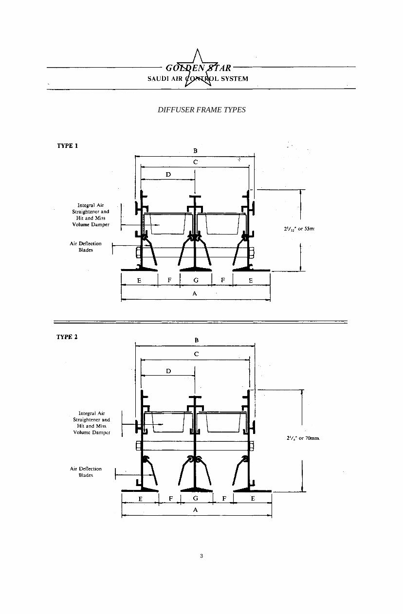
DIFFUSER FRAME TYPES
3

SLOT DIFFUSER DIMENSIONS
AIR DEFLECTION PATTERNS
4

INSTALLATION DETAILS
NOTE; Typical application for type 2 frame.
NOTE: Typical application for type 2 frame.
5

C/STANDARD FIXING ARRANGEMENTS.
NOTE: Typical application for type 2 frame.
HOW TO ORDERSPECIFY:
1. Frame type.2. Quantity required and number of slots.3. Length.4. End Cap arrangements.5. With or without Plenum Box.6. Type of fastening.
6

OPTIONAL PLENUM BOX ASSEMBLES
NOTE:1. Optional 1/2" insulation.2. Side inlet available with 5" & 6" round and oval for all other sizes. See table 2 below
for suggested inlet sizes.3. Available in nominal length of 24, 30, 36, 48, 60 and 72 inches.4. Multi-inlet sizes available upon request.
TABLE 1 . PLENUM BOX DIMENSIONS
7
TABLE 2 . SUGGESTED INLET SIZES

SUPPLY PERFORMANCE DATA FOR PLENUM APPLICA TIONS
3/4" Sl.OT WIDTH. PARALLEL DISCHARGE
N.B. AVAILABLE AL.SO UPTO 5 and 6 SLOTS.
3/4" SLOT WIDTH, PERPENDICULAR DISCHARGE
8
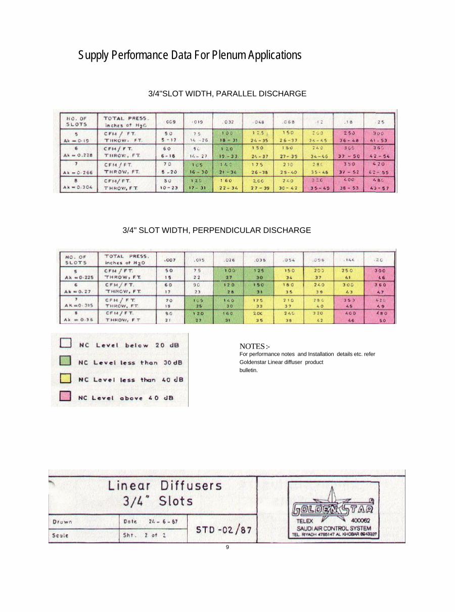
Supply Performance Data For Plenum Applications
3/4"SLOT WIDTH, PARALLEL DISCHARGE
3/4" SLOT WIDTH, PERPENDICULAR DISCHARGE
NOTES:-For performance notes and Installation details etc. referGoldenstar Linear diffuser productbulletin.
9

DIMENSIONAL DATA (5 thru8 slots)
A B C D E F Gno. OFSLOTS
in inm. in. mm. in. mm. in. mm. in. mm. in. mm. in. mm
5 9 228.6 7 23/32 196.1 7 13/32 188 1 9/16 39.7 1 1/8 28.6 3/4 19 3/4 19
6 10 ½ 266.7 9 1/4 235 8 15/16 227 1 9/16 39.7 1 1/8 28.6 3/4 19 3/4 19
7 12" 305 10 3/4 273.5 10 14/32 265.5 1 9/16 39.7 1 1/8 28-6 3/4 19 3/4 19
8 13 17/32 343.7 12 9/32 312 12 304 1 9/16 39.7 1 1/8 28.6 3/4 19 3/4 19
10

SUPPLY PERFORMANCE DATA for PLENUM APPLICATIONSPARALLEL DISCHARGE
1/2"SLOT WIDTH
PERPENDICULAR DISCHARGE
NOTE: All performance notes are same as publisher on 3/4" slotLinear diffuser catalog.
Throw data is based on all slots dischargeair in the same direction. For two way pattern select throws onbasis of CFM/ft per number of slots blowing in each direction.
11
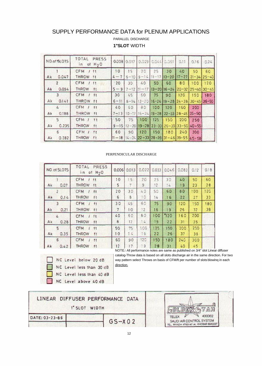
SUPPLY PERFORMANCE DATA for PLENUM APPLICATIONSPARALLEL DISCHARGE
1"SLOT WIDTH
PERPENDICULAR DISCHARGE
NOTE : All performance notes are same as published on 3/4" slot Linear diffusercatalog-Throw data is based on all slots discharge air in the same direction. For twoway pattern select Throws on basis of CFM/ft per number of slots blowinq in eachdirection.
12

RETURN PERFORMANCE DATA for PLENUM APPLICATIONS 1/2" SLOT WIDTH
1"SLOT WIDTH
NOTE: All performance notes are same as published on 3/4" slotLinear diffuser catalog,
Performance ratings shown are based on without hit andmiss volume damper and deflector at full open position.
13

PERFORMANCE NOTES
THROW
The distance measured in ft. that the air travels from outlet at a given terminal velocity. The throw isbased on a 6 ft. length of diffuser. For ceiling higher than 9 ft. in height, reduce the given throw by 1 ft.for every 1 ft. increase in height. It is also based on the slot where the air have been discharged in thesame direction.
PARALLEL THROWS
Values based on one direction, and based on a maximum terminal velocity af 50 fpm. and aminimum terminal velocity of 100 fpm.
<
PERPENDICULAR THROWS
Is to a terminal velocity of 50 fpm.
SOUND DATANoise Criteria (NC), db, based on 8 db room attenuation and a 4 ft. long unit, re: 1012 watt.
FIELD TESTING1. Air velocity measurements can be determined from the branch duct to calculate the CFM. If it's not
possible, air flow rate can be determined from the effective velocity measured from severalreadings along the slot lengths of the diffuser using a pitot tube, Alnor Jet no. 2220 A orAnemotherm (see sketch). Take the mean value of the effective velocity (Vk).
2. Calculate CFM.
Total CFM = Ak X Vk X L
Where:Ak = effective area/ft.Vk = effective velocity.
L = length at which the reading was taken.
14


![089 a 71 053 036 018 [bar] Slot Die Pressure Distribution Slot Die For 2 Layers Streamline Slide Die For 2 Layers Slot Die Coating Slot Die Coating Station High precision slot die](https://img.dokumen.tips/doc/110x75/5e7db07b5e50ba621c17be72/089-a-71-053-036-018-bar-slot-die-pressure-distribution-slot-die-for-2-layers.jpg)