Embed Size (px)
Citation preview

Artisan Technology Group is your source for quality new and certified-used/pre-owned equipment
• FAST SHIPPING AND DELIVERY
• TENS OF THOUSANDS OF IN-STOCK ITEMS
• EQUIPMENT DEMOS
• HUNDREDS OF MANUFACTURERS SUPPORTED
• LEASING/MONTHLY RENTALS
• ITAR CERTIFIED SECURE ASSET SOLUTIONS
SERVICE CENTER REPAIRSExperienced engineers and technicians on staff at our full-service, in-house repair center
WE BUY USED EQUIPMENTSell your excess, underutilized, and idle used equipment We also offer credit for buy-backs and trade-inswww.artisantg.com/WeBuyEquipment
REMOTE INSPECTIONRemotely inspect equipment before purchasing with our interactive website at www.instraview.com
LOOKING FOR MORE INFORMATION? Visit us on the web at www.artisantg.com for more information on price quotations, drivers, technical specifications, manuals, and documentation
Contact us: (888) 88-SOURCE | [email protected] | www.artisantg.com
SMViewInstra

EXM Expansion Interface Specification
RadiSys® Corporation
15025 S.W. Koll Parkway
Beaverton, OR 97006
Phone: (503) 646-1800
Fax: (503) 646-1850
07-0208-00 February 1994
Artisan Technology Group - Quality Instrumentation ... Guaranteed | (888) 88-SOURCE | www.artisantg.com

EXM Expansion Interface Specification
Artisan Technology Group - Quality Instrumentation ... Guaranteed | (888) 88-SOURCE | www.artisantg.com

EXM Expansion Interface Specification
The EXM expansion interface is an I/O interface that provides local expansion of embedded PCs. The purpose of this document is to publish the mechanical and electrical specifications of this expansion interface. This document is organized as follows:
• EXM Expansion Interface concept • Mechanical Specifications • Pin-outs and Signal Definitions
EXM Expansion Interface Concept History The EXM expansion interface was a logical outgrowth of the embedded PC marketplace that began to emerge in the late 1980s. Embedded PCs, which consist of personal computer electronics that have been incorporated into the form factor of an industrial system bus, have become a popular alternative to attaching desktop PCs to industrial systems (a practice that became popular in the mid-80s). Embedded PCs are typically utilized as human interface processors to embedded control systems. The first embedded PCs consisted merely of a PC electronics board to which the peripherals were attached via cables. These first products offered virtually no local I/O expansion capabilities. Soon thereafter, floppy and hard disk units became available that mechanically mounted into the industrial bus card cages. These mass storage units greatly simplified the systems integration time required for embedded PC systems. The next progression brought about the capability to expand the embedded PC's local I/O functionality with standard PC add-in cards. This was implemented by a special PC adapter module that physically carried a PC card within the industrial bus form factor. Unfortunately, this solution was mechanically limited to expansion of only one 8-bit I/O card. By this time, it was becoming clear that what was needed was a standard way to easily expand the embedded PC's local capabilities.
Page 1
Artisan Technology Group - Quality Instrumentation ... Guaranteed | (888) 88-SOURCE | www.artisantg.com
EXM Expansion Interface Specification The EXM expansion interface was developed in 1989 by RadiSys Corporation. It was conceived as a viable solution for local I/O expansion for a variety of system form factors such as VME (the most popular 32-bit industrial bus), VXI (the emerging standard for instrumentation) and EMC (a low cost, small, stand-alone form factor). The EXM expansion interface standardizes the local expansion of embedded PCs in a modular, reliable, space effective, and cost effective manner. It allows the addition of up to 8 expansion modules per embedded PC. Because the EXM expansion interface is electrically similar to the standard PC ISA bus, standard PC software can be used with all EXM modules. The EXM expansion interface specifications were released into the public domain in October 1989.
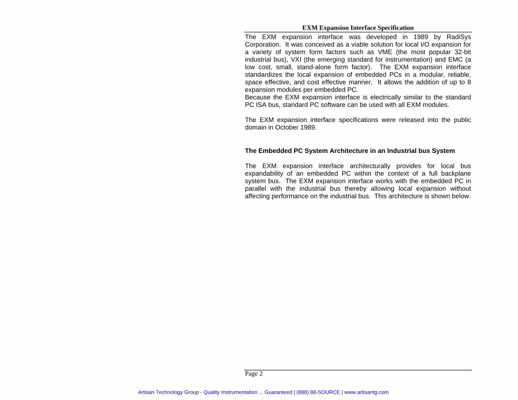
The Embedded PC System Architecture in an Industrial bus System The EXM expansion interface architecturally provides for local bus expandability of an embedded PC within the context of a full backplane system bus. The EXM expansion interface works with the embedded PC in parallel with the industrial bus thereby allowing local expansion without affecting performance on the industrial bus. This architecture is shown below.
Page 2
Artisan Technology Group - Quality Instrumentation ... Guaranteed | (888) 88-SOURCE | www.artisantg.com
EXM Expansion Interface Specification
32-bit Industrial bus
16-bit EXM expansion interface
EPC
MassStorage
(Hard Disk& Floppy)
EXM
This interface provides a local path by which an embedded PC CPU module can communicate with expansion modules allowing the embedded PC to be locally expanded, while retaining its identity as a single logical unit on the host bus. Architecturally, anything that would normally be included inside an attached PC, can now be included locally with an embedded PC. This allows the embedded PC to truly function as a complete PC sub-system.
Page 3
Artisan Technology Group - Quality Instrumentation ... Guaranteed | (888) 88-SOURCE | www.artisantg.com

EXM Expansion Interface Specification Local expansion modules typically include some of the following functions:
* Video graphics adapters * Ethernet LAN cards * Modem interfaces
* Disk controllers and drives * Solid-state disks * Additional serial I/O lines
* IEEE 488 interfaces * Adapter to hold PC add-in cards Subplane Structure for EXM Expansion Interface in a VMEbus System The obstacle here is that the VMEbus consumes all 96 pins of the P1 backplane connector as well as 32 pins of the P2 connector. The remaining number of "user defined" pins on the P2 connector is inadequate to route an auxiliary I/O bus such as the EXM expansion interface. Thus, the EXM expansion interface introduced a new concept for routing local I/O signals within the constraints of pin-limited host bus systems. This new concept involves the use of an intermediary backplane assembly that is called a subplane. The subplane overlays the standard host bus, and passes the appropriate VMEbus signals (Row B) from the CPU through to the host bus. The subplane also carries the EXM expansion interface signals, and routes those signals to connectors available for EXM expansion modules. Software Compatibility with PC/AT Add-in Cards One of the more important aspects of the EXM expansion interface is its software compatibility with the PC/AT bus. This is a key factor since PC expansion products are normally both hardware and software products. By maintaining software compatibility, standard PC add-in boards can be "cloned" into the EXM expansion interface mechanical form factor with no modification necessary to the supporting software. Software Controlled Configuration One area where the electrical protocol of the EXM expansion interface differs from the PC/AT bus is in the addition of software controlled configuration. A special EXMID signal line has been included in the EXM expansion interface definition that facilitates board geographic addressing. This allows the CPU to individually address identification and configuration registers on each EXM expansion module, thus eliminating nearly all configuration jumpers or switches.
Page 4
Artisan Technology Group - Quality Instrumentation ... Guaranteed | (888) 88-SOURCE | www.artisantg.com

EXM Expansion Interface Specification This facility has been added in such a way that it is totally transparent to PC add-in card software. This is accomplished by a special BIOS configuration program that stores the desired system configuration in battery backed-up CMOS memory, and then writes the configuration parameters to each EXM expansion module upon power-up. Since the BIOS performs this configuration before the O/S and PC add-in card software are loaded, the configuration process is completely transparent. This BIOS configuration program also checks for any mis-match errors in the configuration table compared to the actual installed hardware. This allows the user to quickly identify and correct configuration errors. Three 8-bit registers are contained on each EXM module. These three registers are accessed at local I/O address 100h, 102h, and 103h; with only the board whose EXMID signal is asserted responding to reads/writes. The read-only register at 100h contains the module identification, and the read/write registers at 102h and 103h contain the configuration parameters. The EXMID signal is implemented through a 3-line to 8-line decoder on the backplane (or subplane). It is used as an "enable" (or slot select) bit for all of the configuration registers in a single EXM slot. The decoder is located at 96h in the standard I/O space. The implementation is such that a write to 96h enables a single EXM to respond to reads/writes of the configuration registers. For example: writing a 2 to address 96h, enables the EXM module in slot 2 to respond to reads/writes at addresses 100h, 102h, and 103h. Concurrently, this write to 96h also disables all other EXM slots from responding. See diagram below.
0 1 2 3 4 5 6 7
Slot 0 Slot 1 Slot 2 Slot 3 Slot 4 Slot 5 Slot 6 Slot 7
3 line to 8 line decoder
Write data value 0 -7 to 96h
Page 5
Artisan Technology Group - Quality Instrumentation ... Guaranteed | (888) 88-SOURCE | www.artisantg.com

EXM Expansion Interface Specification A list of previously used module ID values is maintained by RadiSys Corporation. If you are creating your own EXM module, contact RadiSys Technical Support to have a new EXMID assigned. The address and telephone numbers are listed below. RadiSys Corp. 15025 S.W. Koll Parkway Beaverton, OR 97006 Phone: (800) 950-0044 (503) 646-1800 Fax: (503) 646-1850
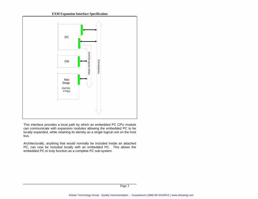
Mechanical Specifications EXM Card - All dimensions are measured in inches +/- 0.01. Note that the cardedge is beveled. Refer to the diagram on the following page.
Page 6
Artisan Technology Group - Quality Instrumentation ... Guaranteed | (888) 88-SOURCE | www.artisantg.com
EXM Expansion Interface Specification
Page 7
Artisan Technology Group - Quality Instrumentation ... Guaranteed | (888) 88-SOURCE | www.artisantg.com

EXM Expansion Interface Specification Faceplate Information
All EXM faceplates are covered with a custom-color lexan and a custom-blue silkscreening. Alternately, the faceplate can be painted using Sherwin-Williams paint #F99TXA564 which is a close approximation of the lexan color. The EXM module is held in place by two front-panel spring-type thumbscrews, PEM part #PF32-440-30CN. The following fonts are used for faceplate lettering:
Page 8
Artisan Technology Group - Quality Instrumentation ... Guaranteed | (888) 88-SOURCE | www.artisantg.com

EXM Expansion Interface Specification Backplane (or subplane) Connector - The backplane connector is an AMP 650090-1 or equivalent. The pin assignment is shown below.
A1 B1
A58 B58
EXM cardedge connector - The EXM expansion connector on the rear of the EXM is a 116-pin cardedge connector.
Page 9
Artisan Technology Group - Quality Instrumentation ... Guaranteed | (888) 88-SOURCE | www.artisantg.com

EXM Expansion Interface Specification Electrical Specifications
The EXM expansion interface is electrically similar to the PC/AT bus for software compatibility. However, there are several differences that should be noted.
• DMA channel 7 does not exist.
• IRQ10 does not exist.
• EXMID has been added to support software configuration of EXMs at power-up.
• RESET is inverted to provide better noise immunity.
• 15 GND lines are provided (compared to 4 on the PC/AT bus) for better noise immunity.
• SA17 - SA19 do not exist. These are redundant (latched) equivalents of LA17 - LA19.
All reserved pins should not be used. These signals are used by some RadiSys products for special purposes.
For further electrical specifications and timing diagrams, see the IEEE P996 "Personal Computer Bus" specification.
Page 10
Artisan Technology Group - Quality Instrumentation ... Guaranteed | (888) 88-SOURCE | www.artisantg.com

EXM Expansion Interface Specification
Pin-outs and Signal Definitions The connector pin numbers are divided into the A side and the B side. Pins A1 through A58 are on the component side of the board with pin A1 at the bottom of the board (away from the key). Pins B1 through B58 are on the solder side of the board with pin B1 at the bottom of the board (away from the key). The pin assignments are listed in the tables below followed by signal definitions.
Page 11
Artisan Technology Group - Quality Instrumentation ... Guaranteed | (888) 88-SOURCE | www.artisantg.com

EXM Expansion Interface Specification
A Row:
Pin Signal Pin SignalA1 +12V A30 -DACK5A2 (reserved) A31 -DACK3A3 +5V A32 -DACK2A4 +5V A33 -MASTERA5 SD15 A34 -DACK1 A6 SD13 A35 -DACK0A7 SD11 A36 -SBHE A8 -12V A37 +5V A9 SD9 A38 AEN
A10 SD7 A39 LA23 A11 SD5 A40 LA21 A12 +12V A41 LA19 A13 SD3 A42 LA17 A14 SD1 A43 TC A15 IRQ15 A44 SA15 A16 IRQ12 A45 SA13 A17 IRQ11 A46 (key) A18 IRQ7 A47 (key) A19 IRQ5 A48 SA11 A20 +5V A49 SA9 A21 -EXMID A50 OSCA22 -IOCHK A51 SA7 A23 DRQ6 A52 SA5 A24 DRQ5 A53 SA3 A25 DRQ3 A54 SA1 A26 DRQ2 A55 +5V A27 DRQ1 A56 +5V A28 DRQ0 A57 (reserved) A29 -DACK6 A58 +12V
Page 12
Artisan Technology Group - Quality Instrumentation ... Guaranteed | (888) 88-SOURCE | www.artisantg.com

EXM Expansion Interface Specification B Row:
Pin Signal Pin SignalB1 GND B30 -IOR B2 (reserved) B31 -SMEMWB3 GND B32 -SMEMRB4 GND B33 GND B5 SD14 B34 -MEMWB6 SD12 B35 -MEMR B7 SD10 B36 BALE B8 GND B37 CLK B9 SD8 B38 GND
B10 SD6 B39 LA22 B11 SD4 B40 LA20 B12 GND B41 LA18 B13 SD2 B42 SA16 B14 SD0 B43 GNDB15 IRQ14 B44 SA14 B16 GND B45 SA12 B17 IRQ9 B46 (key) B18 IRQ6 B47 (key) B19 IRQ4 B48 SA10 B20 IRQ3 B49 SA8 B21 -RSTDRV B50 GND B22 GND B51 SA6 B23 IOCHRDY B52 SA4 B24 -0WS B53 SA2 B25 -IOCS16 B54 SA0 B26 -MEMCS16 B55 GNDB27 -REFRESH B56 GNDB28 GND B57 (Reserved) B29 -IOW B58 GND
Page 13
Artisan Technology Group - Quality Instrumentation ... Guaranteed | (888) 88-SOURCE | www.artisantg.com

EXM Expansion Interface Specification The signal definitions below are listed in alphabetical order. Signal definitions preceded by a are copied from the IBM AT Technical Reference Manual. Some liberties have been taken to correct the definitions for use with the RadiSys 8 MHz bus speed.
-0WS (I) The 'zero wait state' signal tells the microprocessor that it can complete the present bus cycle without inserting any additional wait cycles. In order to run a memory cycle to a 16-bit device without wait cycles, 0WS is derived from an address decode gated with a Read or Write command. In order to run a memory cycle to an 8-bit device with a minimum of two wait states, 0WS should be driven active one clock cycle after the Read or Write command is active, and gated with the address decode for the device. Memory Read and Write commands to an 8-bit device are active on the falling edge of CLK. 0WS is active low and should be driven with an open collector or tri-state driver capable of sinking 20 mA.
AEN (O) The 'address enable' signal is used to degate the microprocessor and other devices from the I/O channel to allow DMA transfers to take place. When this line is active, the DMA controller has control of the address bus, the data-bus Read command lines (memory and I/O), and the Write command lines (memory and I/O). This signal is active high.
BALE (O) (buffered) The 'buffered address latch enable' signal is provided by the Bus Controller and is used to latch valid addresses and memory decodes from the microprocessor. It is available to the I/O channel as an indicator of a valid microprocessor or DMA address (when used with 'address enable' signal, AEN). Microprocessor addresses SA0 through SA23 are latched with the falling edge of BALE. BALE is forced high (active) during DMA cycles.
CLK (O) This is the 8-MHz system 'clock' signal. It is a synchronous microprocessor cycle clock with a cycle time of 125 nanoseconds. The clock has a 50% duty cycle. This signal should be used only for synchronization. It is not intended for uses requiring a fixed frequency.
-DACK0 through -DACK3, -DACK5, & -DACK6 (O) -DMA acknowledge signals are used to acknowledge DMA requests. These signals are active low.
DRQ0 through DRQ3, DRQ5, DRQ6 (I)
Page 14
Artisan Technology Group - Quality Instrumentation ... Guaranteed | (888) 88-SOURCE | www.artisantg.com

EXM Expansion Interface Specification The 'DMA request' signals are asynchronous channel requests used by peripheral devices and a microprocessor to gain DMA service (or control of the system). They are prioritized, with DRQ0 having the highest priority and DRQ6 the lowest. A request is generated by bringing a DRQ line to an active (high) level. A DRQ line is held high until the corresponding 'DMA acknowledge' (DACK) line goes active. DRQ0 through DRQ3 perform 8-bit DMA transfers, DRQ5 and DRQ6 perform 16-bit transfers. DRQ4 is used on the system board and is not available on the I/O channel. -EXMID (O) All EXM expansion modules have configuration registers addressable at 100h, 102h, and 103h in the local I/O space. The EXMID signal is used by the processor to specify which EXM slot should respond to reads/writes of these addresses.
-I/OCHK (I) The 'I/O channel check' signal provides the system board with parity (error) information about memory or devices on the I/O channel. When this signal is active (low), it indicates a non-correctable system error.
-I/OCHRDY (I) The 'I/O channel ready' signal is pulled low (not ready) by a memory or I/O device to lengthen I/O or memory cycles. Any slow device using this line should drive it low immediately upon detecting its valid address and a Read or Write command. Machine cycles are extended by an integral number of clock cycles (125 nanoseconds). This signal should be held low for no more than 2.5 microseconds.
-I/OCS16 (I) The 'I/O 16-bit chip select' signal indicates to the system that the present data transfer is a 16-bit I/O cycle. It is derived from an address decode. -I/OCS16 is active low and should be driven with an open collector or tri-state driver capable of sinking 20 mA.
-IOR (I/O) The '-I/O read' signal instructs an I/O device to drive its data onto the data bus. This signal may be driven by the system microprocessor or DMA controller, or by a microprocessor or DMA controller resident on the I/O channel. This signal is active low.
-IOW (I/O)
Page 15
Artisan Technology Group - Quality Instrumentation ... Guaranteed | (888) 88-SOURCE | www.artisantg.com
EXM Expansion Interface Specification The '-I/O write' signal instructs an I/O device to read the data off the data bus. It may be driven by any microprocessor or DMA controller in the system. This signal is active low.
IRQ3 through IRQ7, IRQ9, IRQ11, IRQ12, IRQ14, & IRQ15 (I) Interrupt requests 3 through 7, 9, 11, 12, 14, and 15 are used to signal the microprocessor that an I/O device needs attention. The interrupt requests are prioritized, with IRQ9, IRQ11, IRQ12, IRQ14 and IRQ15 having the highest priority (IRQ9 is the highest), and IRQ3 through IRQ7 having the lowest priority (IRQ7 is the lowest). An interrupt request is generated when an IRQ line is raised from low to high. The line is high until the microprocessor acknowledges the interrupt request (Interrupt service routine).
LA17 through LA23 (I/O) These signals (unlatched) are used to address memory and I/O devices within the system. They give the system up to 16M of addressability. These signals are valid when BALE is high. LA17 through LA23 are not latched during microprocessor cycles and therefore do not stay valid for the whole cycle. Their purpose is to generate memory decodes for 16-bit, 1 wait-state, memory cycles. These decodes should be latched by I/O adapters on the falling edge of BALE.
-MASTER (I) This signal is used with a DRQ line to gain control of the system. A processor or DMA controller on the I/O channel may issue a DRQ to a DMA channel in cascade mode and receive a -DACK. Upon receiving the -DACK, a microprocessor may pull -MASTER active (low), which will allow it to control the system address, data, and control lines (a condition known as tri-state). After -MASTER is low, the microprocessor must wait one clock cycle before driving the address and data lines, and two clock cycles before issuing a Read or Write command. If this signal is held low for more than 15 microseconds, the system memory may be lost because of a lack of refresh.
-MEMCS16 (I) The '-memory 16-bit chip select' signal indicates to the system that the present data transfer is a 16-bit memory cycle. It must be derived from the decode of LA17 through LA23. -MEMCS16 is active low and should be driven with an open collector or tri-state driver capable of sinking 20 mA.
OSC (O)
Page 16
Artisan Technology Group - Quality Instrumentation ... Guaranteed | (888) 88-SOURCE | www.artisantg.com

EXM Expansion Interface Specification The 'oscillator' signal is a high-speed clock with a 70-nanosecond period (14.31818 MHz). This signal is not synchronous with the system clock. It has a 50% duty cycle.
-REFRESH (I/O) This signal is used to indicate a refresh cycle and can be driven by a microprocessor on the I/O channel. This signal is active low.
-RSTDRV (O) The 'reset drive' signal is used to reset or initialize system logic at power-up time or during a low voltage condition. This signal is active low.
SA0 through SA16 (I/O) Address signals 0 through 16 are used to address memory and I/O devices within the system. These address lines, in addition to LA17 through LA23, allow access of up to 16M of memory. SA0 through SA16 are gated on the system bus when 'buffered address latch enable' signal (BALE) is high and are latched on the falling edge of BALE. These signals are generated by the microprocessor or DMA controller. They also may be driven by other microprocessors or DMA controllers that reside on the I/O channel.
-SBHE (I/O) The '-system bus high enable' signal indicates a transfer of data on the upper byte of the data bus, SD8 through SD15. 16-bit devices use -SBHE to condition data bus buffers tied to SD8 through SD15. This signal is active low.
SD0 through SD15 (I/O) These signals provide bus bits 0 through 15 for the microprocessor, memory, and I/O devices. D0 is the least-significant bit and D15 is the most-significant bit. All 8-bit devices on the I/O channel should use D0 through D7 for communications to the microprocessor. The 16-bit devices will use D0 through D15. To support 8-bit devices, the data on D8 through D15 will be gated to D0 through D7 during 8-bit transfers to these devices; 16-bit microprocessor transfers to 8-bit devices will be converted to two 8-bit transfers.
Page 17
Artisan Technology Group - Quality Instrumentation ... Guaranteed | (888) 88-SOURCE | www.artisantg.com
EXM Expansion Interface Specification
-SMEMR (O) -MEMR (I/O) These signals instruct the memory devices to drive data onto the data bus. -SMEMR is active only when the memory decode is within the low 1M of memory space. -MEMR is active on all memory read cycles. -MEMR may be driven by any microprocessor or DMA controller in the system. -SMEMR is derived from -MEMR and the decode of the low 1M of memory. When a microprocessor on the I/O channel wishes to drive -MEMR, it must have the address lines valid on the bus for one clock cycle before driving -MEMR active. Both signals are active low.
-SMEMW (O) -MEMW (I/O) These signals instruct the memory devices to store the data present on the data bus. -SMEMW is active only when the memory decode is within the low 1M of the memory space. -MEMW is active on all memory write cycles. -MEMW may be driven by any microprocessor or DMA controller in the system. -SMEMW is derived from -MEMW and the decode of the low 1M of memory. When a microprocessor on the I/O channel wishes to drive -MEMW, it must have the address lines valid on the bus for one clock cycle before driving -MEMW active. Both signals are active low.
TC (O) The 'terminal count' signal provides a high pulse when the terminal count for any DMA channel is reached.
RadiSysCORPORATION
Page 18
Artisan Technology Group - Quality Instrumentation ... Guaranteed | (888) 88-SOURCE | www.artisantg.com

®
RadiSysCORPORATION
15025 S.W. Koll Parkway • Beaverton, OR 97006 • (503) 646-1800
Artisan Technology Group - Quality Instrumentation ... Guaranteed | (888) 88-SOURCE | www.artisantg.com

RadiSysCORPORATION
15025 S.W. Koll Parkway • Beaverton, OR 97006 • (503) 646-1800
Artisan Technology Group - Quality Instrumentation ... Guaranteed | (888) 88-SOURCE | www.artisantg.com

Artisan Technology Group is your source for quality new and certified-used/pre-owned equipment
• FAST SHIPPING AND DELIVERY
• TENS OF THOUSANDS OF IN-STOCK ITEMS
• EQUIPMENT DEMOS
• HUNDREDS OF MANUFACTURERS SUPPORTED
• LEASING/MONTHLY RENTALS
• ITAR CERTIFIED SECURE ASSET SOLUTIONS
SERVICE CENTER REPAIRSExperienced engineers and technicians on staff at our full-service, in-house repair center
WE BUY USED EQUIPMENTSell your excess, underutilized, and idle used equipment We also offer credit for buy-backs and trade-inswww.artisantg.com/WeBuyEquipment
REMOTE INSPECTIONRemotely inspect equipment before purchasing with our interactive website at www.instraview.com
LOOKING FOR MORE INFORMATION? Visit us on the web at www.artisantg.com for more information on price quotations, drivers, technical specifications, manuals, and documentation
Contact us: (888) 88-SOURCE | [email protected] | www.artisantg.com
SMViewInstra


![Compact and Broadband Microstrip-Line-Fed Modified …tie slot antenna with a rectangular tuning stub [14] or a coplanar waveguide (CPW)-fed rhombus slot antenna with a rhombic ring](https://img.dokumen.tips/doc/110x75/5e350409078c6c664e67ae66/compact-and-broadband-microstrip-line-fed-modified-tie-slot-antenna-with-a-rectangular.jpg)


![Printed Egg Curved Slot Antennas for Wideband Applications · wide-slot antenna fed by a microstrip line with a rotated slot for bandwidth enhancement is proposed in [1] with operating](https://img.dokumen.tips/doc/110x75/5fd1ea513ac4222b78003805/printed-egg-curved-slot-antennas-for-wideband-wide-slot-antenna-fed-by-a-microstrip.jpg)