Embed Size (px)
Citation preview

CITY OF LIVONIA DEPARTMENT OF PUBLIC WORKS
ENGINEERING DIVISION
SITE PLAN DESIGN STANDARDS
Engineering Division CITY OF LIVONIA 33000 CIVIC CENTER DRIVE LIVONIA, MI 48154 Phone: (734) 466-2570 March 2015

Introduction The following design standards are intended to provide a basis upon which commercial, and residential sites within the City of Livonia are to be designed. The requirements outlines herein reflect the requirements of the Livonia Engineering Division and conform to current engineering practices in Western Wayne County, Michigan. By no means are these standards intended as a substitute for sound professional engineering judgment. CONTENTS I. GENERAL RQUIREMENTS AND PROCEDURES Pages 1 - 7
II. SURVEY Pages 7 - 8
III. SOIL EROSION AND SEDIMENTATION CONTROL Pages 8 - 9
IV. WATER MAIN Pages 9 - 13
V. SANITARY SEWER Pages 13 - 18
VI. STORM SEWER Pages 18 - 26
VII. PAVING AND GRADING Pages 26 - 39
VIII. APPENDIX
A. Standard Construction Notes
B. Standard Notes for Crossing Roads By Tunneling, Boring or Jacking
C. Grading Certificate Submission Criteria
D. Soil Erosion and Sedimentation Plan Checklist
E. Plot Plan Submission Criteria
F. Wayne County Department of Environmental “Sanitary Sewer Approval Checklist”
G. Michigan Department of Environmental Quality “guidelines and Permit Application for Wastewater Systems”
H. Michigan Department of Environmental Quality “Permit Application for Water Supply Systems”
I. Procedures for Demolition and Removal of Buildings
J. Wayne County Permit Specifications for work within “Wayne County Right-of-Way”
Page | 1 of 29
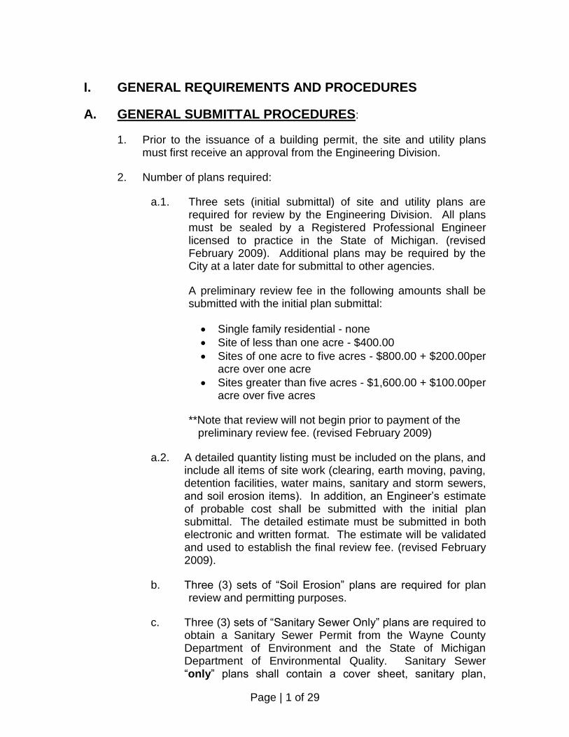
I. GENERAL REQUIREMENTS AND PROCEDURES
A. GENERAL SUBMITTAL PROCEDURES:
1. Prior to the issuance of a building permit, the site and utility plans must first receive an approval from the Engineering Division.
2. Number of plans required:
a.1. Three sets (initial submittal) of site and utility plans are required for review by the Engineering Division. All plans must be sealed by a Registered Professional Engineer licensed to practice in the State of Michigan. (revised February 2009). Additional plans may be required by the City at a later date for submittal to other agencies.
A preliminary review fee in the following amounts shall be submitted with the initial plan submittal:
Single family residential - none
Site of less than one acre - $400.00
Sites of one acre to five acres - $800.00 + $200.00per acre over one acre
Sites greater than five acres - $1,600.00 + $100.00per acre over five acres
**Note that review will not begin prior to payment of the preliminary review fee. (revised February 2009)
a.2. A detailed quantity listing must be included on the plans, and include all items of site work (clearing, earth moving, paving, detention facilities, water mains, sanitary and storm sewers, and soil erosion items). In addition, an Engineer’s estimate of probable cost shall be submitted with the initial plan submittal. The detailed estimate must be submitted in both electronic and written format. The estimate will be validated and used to establish the final review fee. (revised February 2009).
b. Three (3) sets of “Soil Erosion” plans are required for plan review and permitting purposes.
c. Three (3) sets of “Sanitary Sewer Only” plans are required to obtain a Sanitary Sewer Permit from the Wayne County Department of Environment and the State of Michigan Department of Environmental Quality. Sanitary Sewer “only” plans shall contain a cover sheet, sanitary plan,
Page | 2 of 29
profile sheet, and the City of Livonia Sanitary Sewer Standard Detail Sheets along with a completed MDEQ Waste Water System permit application. A plan review and permit fee will be required to accompany the plans.
d. Three (3) sets of water main “only” plans will be required to obtain a water permit from the State of Michigan Department of Environmental Quality (MDEQ). Water main “only” plans shall contain a cover sheet, water main plan sheet, and the City of Livonia Water Main Standard Detail Sheet along with a completed MDEQ Water Supply System Permit Application.
3. The Design Engineer shall make a separate submittal to Wayne County for work within their right-of-way such as drive approaches, utility taps and detention facilities that are under their jurisdiction.
4. Upon completion of the review, the City will return one set of plans to the Engineer or Architect with revisions and/or corrections noted on the plans. Direction will be given at the time as to how many plans must be resubmitted.
5. After the review, comments and corrections have been addressed by the Engineer or Architect, a meeting with the review engineer is encouraged to resolve all comments.
6. Upon Engineering approval, notification will be given to the Building Division that the site plan is approved.
7. Partial approvals will not be given. All revision on all phases must be made prior to Engineering approval.
8. An Engineering Permit will not be issued until all required fees as noted above and inspection escrow accounts have been deposited and the necessary permits obtained.
B. FEES: ENGINEERING FEES As of 1/22/04 Ordinance Section Fees 12.04.090 A. Processing Fee $7.00 Utility Companies $290.00
Page | 3 of 29
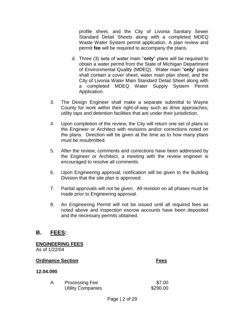
B. 1. Sidewalks $0.08 Per Sq Ft. ($20.00 Minimum) 2. Drive Approach $40.00 3. Drive Culvert $40.00 4. Curb Cut $40.00 5. Hydrant Use $14.00 + $4.00 per day 6. Water Main Connection – Only $130.00 3” – 6” $130.00 8” and above $180.00
7. Storm Sewer – Tap Only Less than 18” $90.00 18” – 42” $180.00 Larger than 42” $260.00 8. Sanitary Saddle Only $90.00
C. Utility Company Annual Permit $430.00 15.36.060 Soil Erosion Plan Review Single Family $50.00 Less than 1 acre $75.00 1 – 9 acres $75.00 + $50.00 per acre over 1 10 – 40 acres $500.00 + $25.00 per acre over 10 40 or more $1,250.00 + $10.00 per acre over 40 Inspection Single Family $135.00 Ordinance Section Fees 15.36.600 Con’t Less than 1 acre $200.00 1 – 9 acres $200.00 per acre 10 – 40 acres $2,000.00 + $100.00 per acre over 10 40 or more $5,000.00 + $75.00 per acre over 40

Page | 4 of 29
Development Review Fees Plan Review (16.16.080) 2% (on-site construction cost) Inspection Deposit (16.24.380) Construction Cost $0 - $5,000 17% ($ 400.00 minimum) Construction Cost $5,000 - $50,000 12% ($ 800.00 minimum) Construction Cost $50,000 - $100,000 7% ($4,000.00 minimum) Construction Cost $100,000 plus 5% ($6,000.00 minimum) New Fees Plot Plan and Grade Certification (Add to 12.04.090) $75.00 Each Review (Add to 12.04.090) $75.00 Overweight Permit (Add to 10.54.260) $100.00 Soil Erosion Fee
The fee for a Soil Erosion and Sedimentation Control Permit shall be collected prior to site plan approval in accordance with the requirements for a permit under 1994 PA 451 Part 91 (See permit application for specific requirements).
C. GENERAL PLAN REQUIREMENTS:
1. Plans shall be submitted on 24” x 36” white prints, having blue or black lines. Judgment should be exercised in the design, layout and presentation of the proposed improvements. Acceptable scales shall be:
1” = 20’; 1” = 40’; 1” = 50’, according to the size of the site. 2. When the size of the site prohibits the entire site from being shown
on a single pan sheet, a 1” = 100’ or 1” = 200’ general plan must be provided. The general plans should show the streets and their names, pavement, all units, utilities, and site dimensions.
3. The site plan or, if in the case of number 2 above, the general plan
shall also include lot or parcel dimensions and abutting rights-of-way. A location map shall be included on each site plan showing the approximate location of the site relative to major thoroughfares.
4. A legal description of the property must be included.
5. An area map showing the general location of the development isto be
shown on at least one plan sheet.
Page | 5 of 29
6. The City of Livonia Standard Notes shall appear on the plan.
7. All plans submitted for review must be prepared and sealed by a
Professional Engineer licensed to practice in the State of Michigan. All correspondence concerning the design of the site will be directed to the Engineer whose seal appears on the plan. The name, address, and telephone number of the Owner and Engineer shall be shown on the plan.
8. The sanitary sewer and water main shall be shown on the same plan
view. Profiles are required for all public sanitary sewers, storm sewers, and all water main over 12 inches.
All underground utilities and pavements shall be labeled as “Public” or “Private”. In general main line sanitary sewers and water mains must be “Public”.
9. All profiles shall have a vertical scale of 1” = 5’ where applicable.
The profile shall be shown below the plan view where possible, with as close an alignment as possible.
10. When many plan sheets are in the set, each plan sheet shall include
in its title block, a summary of that particular sheet. 11. Benchmarks; at least 2 benchmarks must be indicated on the general
plan, defined on the U.S.G.S. Datum. 12. Sanitary sewer plans shall conform to City of Livonia Standard
Specifications and Details and shall meet the requirements outlined in the Wayne County Department of Environment Sanitary Sewer Approval Checklist (Appendix F).
D. FIELD REQUIREMENTS: 1. The City of Livonia will provide inspection on all public utilities and
improvements in the City right-of-way. Inspection will be full-time on water mains and sanitary sewers and, wherever possible, on storm sewers, and paving. Part-time inspection may be provided at the discretion of the Engineering Division for sidewalk, approaches, taps to public storm sewers, on-site paving, and private storm sewer.
2. A minimum of 48 hours notice is required to ensure the presence of a
City Inspector when work commences.
3. Prior to starting any construction, the Contractor must obtain all required permits.

Page | 6 of 29
4. All public improvements must be field staked under the supervision of the Engineer, or Land Surveyor that prepared the plans. Staking must be in accordance with the approved plans.
5. All construction must conform to the current MIOSHA safety
standards.
6. At the time of final inspection for all public improvements, the Owner or his Contractor shall provide all necessary labor and equipment to allow the City to inspect the system.
7. Generally, one inspector will be assigned to a particular project and
will be responsible for that project until its completion. The contractor and the inspector may make arrangements for day-to-day inspection. Any interruption or moratorium on the flow of work may result in a reassignment of that inspector to another project and require the normal 48-hour notice before work is resumed.
8. At the completion of the project, “as-built” plans and a certification
from the Design Engineer will be required indicating that all work has been completed in accordance with the approved plans. “As-built” plans shall be on mylar material. A computer disk containing AutoCAD and PDF files of the “as-built” plans shall be submitted with the mylar plans and no final occupancy shall be granted until the “as-builts” are approved.
E. PERMIT REQUIREMENTS: 1. Site Plan
The approved site plan constitutes a permit from the Engineering Division for the construction of the site. However, other departments within the City, as well as other agencies, may require additional permits.
The other agencies; such as MDEQ, Michigan Department of Transportation (MDOT), Wayne County Department of Public Works (WCDPS), Detroit Water and Sewer Department (DWSD) permits will generally be listed on the approved plan.
2. Soil Erosion and Sedimentation Control Permit
This permit is required prior to final site plan approval. Applications are available at the City Engineering Division office. A bond may be required in accordance with City Code, Chapter 24, Article III.
Page | 7 of 29
3. Michigan Department of Environmental Quality Water Main
All water mains require a construction permit from the MDEQ. The City will directly request approval from the Department of Environmental Quality during the course of site plan approval.
4. Michigan Department of Environmental Quality Sanitary Sewer
All sanitary sewers require an Environmental Quality Construction Permit from the MDEQ. The City will directly request approval from the MDEQ during the course of site plan approval.
5. Wayne County Department of Public Services
All work in roads under the jurisdiction of the Wayne County Roads Division requires a permit from the Wayne County Department of Public Service.
All new sanitary sewer and sanitary sewer connections require a permit from the Wayne County Department of Public Works Environmental Division.
A permit for storm water detention facilities will be required from Wayne County if the outlet is under their jurisdiction.
6. Other Permits
Other agencies that may require a permit will be designated on the approved plan. These permits are generally the contractor’s responsibility and will generally be required prior to construction:
Detroit Water and Sewer Department Michigan Department of Transportation Michigan Department of Environmental Quality Wayne County Department of Public Services Oakland County Road Commission (Eight Mile Road)
II. SURVEY
A. GENERAL (EXISTING CONDITIONS)
1. A complete topographical survey is required for all sites. Existing off-site evaluations must be given at a minimum of 50’ and 100’ abutting the entire perimeter of the site. Grades shall be indicated at all property corners and along all property lines. On site, intermittent elevations or defined contours are required to establish the existing site drainage.
Page | 8 of 29
2. All existing conditions shall be indicated. Location and elevations must be given on the following:
• Existing drainage courses • Upstream and downstream culverts • All utilities, including sanitary, storm, water main, gas,
telephone, electrical, etc. • Inverts and casting finish grades are requires where
applicable • Sidewalks • Finished grades of all adjacent buildings • All easements
3. U.S.G.S. Benchmarks (2 required)
4. Road topography shall extend across the entire site with grades shown on both sides of the street for:
• Property line • Ditch center line • Top of bank • Edge of shoulder • Edge of pavement or top of curb • Crown or center line
5. Property lines must be indicated by distances and bearings where applicable.
6. Existing rights-of-way of adjacent roads must be indicated.
III. SOIL EROSION AND SEDIMENTATION CONTROL
A. SITES REQUIRING PERMITS
All sites having a construction area of one or more acres require a Soil Erosion Permit. All site within 500 feet of a drainage course require a Soil Erosion Permit.
B. INTENT OF PERMIT
The intent of this requirement is to ensure that no silt or sediment enters the public streams or watercourses. This is accomplished through means of siltation basins, filters, diversion, etc.
Page | 9 of 29
C. PLAN REQUIRED
A soil erosion and sedimentation control plan is required for all sites that require a permit. This can be made a part of the site construction plans or may be a separate plan. Itemized on this plan shall be step-by-step requirements for controlling siltation. No work (including site clearing) will be allowed until approved siltation control measures are in effect.
Accelerated erosion and sedimentation must be prevented during all phases of construction, including:
• Initial site clearing • Utility construction • Building construction • Site Paving • Final site approval
D. INSPECTION
Inspections will be made periodically throughout construction on the maintenance and effectiveness of soil sedimentation control methods.
The costs of these inspections are included in the permit fee. If inspections reveal that the controls are not being implemented, a Cease and Desist Order on all site construction may be issued.
NOTE: THE SILTATION CONTROL REQUIREMENTS MAY CONTROL THE PROGRESS AND SCHEDULING OF ALL CONSTRUCTION ON THE SITE.
IV. WATERMAIN/WATER SYSTEM
A. GENERAL
1 When applicable, the City of Livonia Standard Water Main Notes must appear on the plan. (See Standard Water Main Notes)
2. A quantity list itemizing all proposed public water main construction must appear on the plan.
3. Public water mains are required when two or more connections are
made to the same water main. In most instances, including multiple unit developments, the water main may have to be public, even though the project has one owner
Page | 10 of 29
B. LOCATION OF MAINS
1. 10 ft. off property line in 60 ft. right-of-way.
2. 12 ft. off property line in 86 ft. right-of-way.
C. SIZES AND DISTRIBUTION
1. 8” minimum
2. 12” minimum on the mile roads
3. Six-inch mains may be used only for single fire hydrants leads having maximum length of 75 ft. No service leads are allowed on a six-inch hydrant lead.
4. Maximum dead end mains are as follows:
450 ft. for 8” Mains 1,000 ft. for 12” Mains
5. Reducers are not to meet the dead end requirements.
6. Twelve-inch water main may be considered as minimum for internal transmission on industrial and multiple sites.
7. Looping of mains will be required, wherever possible. All mains must end with a gate valve, hydrant, or blow-off.
8. No private services will be allowed from a water main over 16 inches in diameter.
9. The extension of water main will generally be required across the entire frontage of the site.
D. HYDRANTS
1. Single-family residential spacing shall be a maximum of 500 feet.
2. Commercial, industrial and multiple tenants spacing shall generally be a maximum of 400 feet.
3. Additional hydrants may be required depending on this specific use.
4. Locations: (a) 15 ft. off property line at street intersections

Page | 11 of 29
(b) 30 ft. off lot lines between corners
5. E.J.I.W. Midwest model 6-BR or E.J.I.W. Water Master model 5-BR-250 located a minimum 3’ behind curb.
6. Hydrants that are private shall be yellow.
E. VALVES 1. Gate valve spacing will generally be regulated by providing the
following provision in event of a breakage. In the event of a breakage: a. No more than 24 single family units will lose service. b. No more than 30 multiple units will lose service. c. No more than two hydrants will be out of service. d. No more than three valves shall have to be closed to isolate the break. e. On line valve spacing shall be a maximum of 800 ft.
2. Gate valves shall be located 10 ft. off the property line at street intersections.
3. Gate valve are required on mains, which will be extended in the
future.
4. Gate valve to open counter clockwise.
F. TYPE OF PIPE AND JOINTS
1. All pipes shall be ductile iron meeting U.S.A.S. Spec. A 21.51 thickness – Class 54 or high density polyethylene meeting AWWA C906.
2. Joints to be push-on type on ductile iron pipe or butt fusion welded on
high density polyethylene pipe.
G. MISCELLANEOUS
1. Water mains to be installed 5 ft. below existing or proposed pavement grade.
2. A tapping sleeve, valve, and well are required when tapping existing water line.
Page | 12 of 29
3. ¾” and/ or 1” service lines shall be installed as part of water main project for lots where width of pavement to be bored exceeds 45 ft.
4. A blow-off valve and box, or a hydrant with a line valve and well is required at all dead-ends.
5. 4” of compacted sand bedding shall be provided under all water pipe.
6. All ductile iron water mains are to be poly-wrapped.
7. Service connections to HDPE pipe shall be fusion welded. No saddle connections will be permitted. Fittings shall be joined to HDPE pipe using fusion welded mechanical joint adapters.
H. EASEMENTS
All public water mains must be located in an easement or public right-of-way. Standard easement forms are available at the City Engineering Division. The minimum easement shall be 12 ft. The dedication of the easement will be required prior to acceptance of the system.
I. STANDARD WATER MAIN NOTES
1. PIPE – All water main pipe 16” diameter and smaller shall be Ductile Iron thickness; Class 54, meeting ANSI Spec. A-21.51and shall be lined with a double thickness of cement-mortar meeting ANSI Spec. 21.4 or high density polyethylene pipe meeting AWWA C906 (P.E. 3408)
2. JOINTS – All ductile iron water pipe and fittings shall have push-on joints either “Tyton” or Super Bell-Tite”, except where otherwise noted. HDPE water pipe and fittings shall be butt fusion welded.
3. POLYETHYLENE ENCASEMENT – All ductile iron water pipe and fittings shall be wrapped in 8 mil thick, black, polyethylene, in accordance with ANSI Spec. A-21.5.
4. BEDDING – A minimum of 4”of compacted approved sand (100% passing 3/8” sieve) shall be provided under all water pipe and continued to a level 12” above the pipe.
5. CONNECTIONS TO EXISTING WATER MAINS will not be allowed until the
new lines have passed the pressure test (150 p.s.i. for 1 hr. max loss 50 gal/inch dia./mile/day) and have been satisfactorily disinfected with chlorine (50 ppm – 24 hrs.)
6. FOAM SWABBING – Both the initial flushing and the flushing after
chlorination will be supplemented by passing foam swab through the water

Page | 13 of 29
main. The contractor shall be responsible for providing the required foam swab.
7. TAP FEE – A tap fee must be paid and a bond posted with the Water and
Sewer Department of the City of Livonia prior to beginning any work. In addition, a meter must be obtained from the Water and Sewer Department to meter all water consumed including, flushing and other normal water installation operations.
8. NOTIFICATION – Both the Engineering Division and the City of Detroit Water and Sewer Department must be notified at least 24 hours in advance when any connections are to be made to an existing water main. 24 Hours Notification Required.
9. OPERATING VALVES – The City of Livonia Water Department will open and close all valves on existing lines. No valve on an existing water line is to be operated by anyone other than an authorized Water Department employee.
10. When a PRESSURE TEST is to be made on a new water line, BOTH THE DETROIT WATER AND SEWER DEPARTMENT AND THE LIVONIA ENGINEERING DEPARTMENT MUST BE NOTIFIED 24 HOURS IN ADVANCE and be present for the test, and to verify that all main valves are open and to open all hydrants during the course of the pressure test.
11. FINAL VERIFICATION – When all connections have been made following chlorination and pressure test, the contractor shall notify the Livonia Water Department and the Livonia Engineering Department, they will verify that all valves are left in the “OPEN” position.
. 12. FITTINGS shall be Ductile Iron with push-on joints conforming to ANSI
Specifications 21.10 “Gray Iron and Ductile-Iron Fittings”, “2 through 48”, for Water and other Liquids.
V. SANITARY SEWER
A. GENERAL
1. Public sanitary sewers are required when two or more connections are made to the same sewer. In most instances, including multiple unit developments, the sewers may have to be public, even though the project has one owner.
2. The extension of the sanitary sewers will generally be require across the entire frontage of the site.

Page | 14 of 29
3. All construction shall conform to the current City of Livonia Sanitary Sewer Specifications and Standard Details.
B. CAPACITY Outlet and subdivision sewers to have adequate capacity (based upon 100 gal. per person per day, 3.5 people/REU (Residential Equivalent User), and a peaking factor equal to ½ ½ 18 + (P) / 4 + (P) where P is the population in thousands.
C. LOCATION
1. Sanitary sewers shall be located so as to provide unrestricted access for maintenance and inspection. A minimum alignment separation of 10 ft. must be maintained between the sanitary sewer and all water mains. The water main and sanitary sewer shall be located on opposite sides of the street, wherever possible.
2. Typical Locations:
a. Generally 7 ½ ft. off property line in 60 ft. right-of-way b. Generally 13 ft. off property line in 86 ft. right-of way c. Generally 2 ½ ft. off property line in easements d. Sewer lines to be extended across the entire frontage of site e. Minimum of 2 ft. off property line around curves
3. All public sewers must be located in a public right-of-way or an easement.
Standard Easement forms are available at the City Engineering Division. The easement size will vary individually as required for maintenance and access. The minimum sanitary sewer easement shall be 12’. The dedication of the easement will be required prior to construction of the system.
D. SIZE
1. 10” minimum size for laterals
2. 6” house leads – extended to 5 ft. inside property line
E. MANHOLES
1. A manhole will be required at all changes in alignment, direction, where lines intersect, when pipe size changes, or a change in pipe grade.
Page | 15 of 29
2. The maximum distance between manholes shall be 400’ for sanitary sewer 48” diameter or less.
3. Details shall conform to City of Livonia Standard Detail Sheet.
F. TYPE OF PIPE AND JOINTS
1. ABS composite (truss) pipe conforming to ASTM D-2680, Standard Specifications for Acrylonitrile-Butadiene-Styrene composite pipe. Solvent cement welded joint (ASTM D-2235 and ASTM D-2680).
2. PVC composite pipe conforming to ASTM D-2680 Standard Specifications for Poly-Vinyl-Chloride composite pipe push on (ASTM D-3212) electrometric gasket.
3. Other pipe types and material will be considered if specific locations, or field conditions warrant their use.
G. LEADS
1. Service leads shall be a minimum of 6 inches in diameter with a minimum slope of 1.00%. Leads shall be extended to 5 feet inside the property line.
2. A 4” service line will be allowed for a tap into an existing 10” sanitary sewer main.
3. Materials:
a. ABS solid wall S.D.R. 23.5 conforming to ASTM D-2751 (SDR 23.5) Standard Specifications. Push on (ASTM D-3212) or solvent cemented (ASTM D-3034).
b. PVC solid wall S.D.R. 23.5 conforming to ASTM D-3034 (SDR 23.5) Standard Specifications. Push on (ASTM D-3212) or solvent cemented (ASTM D-3034).
c. ABS Schedule 40 pipe conforming to ASTM D-1527
Standard Specifications. Solvent cemented joint (ASTM D-1527).
d. P.V.C. Schedule 40 pipe conforming to ASTM D-1785 Standard Specifications. Solvent cemented joint (ASTM D-1785)
4. House connections shall not be tapped to manholes.

Page | 16 of 29
5. Wyes shall be provided for each lot abutting sanitary sewers in easement.
6. Wyes and house leads shall be provided to a point 5’. inside the property line for each lot abutting sanitary sewers in streets.
7. Risers shall be installed where necessary to have invert elevations of house connections at the property line 9’ below the sidewalk, or property line grade.
8. Service lead connection to City main shall require Saddle Connection
or approved equal.
H. DROP CONNECTIONS
External drop connections are required where the invert of the outlet pipe is 18 inches or more below the invert of the inlet pipe. Internal drop connections will not be allowed.
I. GRADES
1. Provide a velocity (when running full) of no less than 2 ½ f.p.s. and no more than 8 f.p.s.
2. An absolute minimum velocity of 2 f.p.s. and an absolute maximum
velocity of 10 f.p.s. may be permitted for special cases.
J. PROFILES
The following information shall be indicated on the sanitary sewer profile:
1. Length of run between manholes 2. Type and class of pipe between manholes 3. Size and grade of pipe between manholes
4. Top of casting and invert of all manholes and sewers at
manholes
5. Existing and proposed ground elevation along the route of the sewer
6. Progressive numbering system (number all manholes on plan
and profile sheets)
7. All utility crossings

Page | 17 of 29
8. Special backfill areas
9. Provisions for infiltration testing
K. MISCELLANEOUS
1. Downspouts, weep tile, footing drains, or any conduit that carries storm or ground water shall not be allowed to discharge into the sanitary system.
2. There shall be a 10-foot separation between the proposed sanitary
sewer and the water main. 3. The City of Livonia Standard Sanitary Sewer Notes shall appear on
the plans. 4. A quantity list itemized all proposed public sanitary sewer
construction must appear on the plans. 5. The plans shall also meet the requirements outlined in the Wayne
County Department of Environment, Sanitary Sewer Approval Checklist (see Appendix F).
L. STANDARD SANITARY SEWER NOTES
1. No connections receiving storm water, surface water, or ground water shall be made to sanitary sewers.
2. Infiltration for any sections of sewers between manholes shall not
exceed 100 gal/inch dia./mile/24 hours. 3. No footing drains shall be connected to the building sewer. 4. Differential of excavation around existing manholes shall not
exceed 6’. 5. All manholes and covers shall be in accordance with current
standards of the City of Livonia and the Wayne County Department of Public Works.
6. Testing methods in accordance with current Sewer Use Regulations
of the Wayne County Department of Public Works shall be required prior to approval by the City of Livonia. (Television, air tests, etc.)
7. All sanitary sewer pipes shall be ASTM D-2680 ABS or PVC
composite (truss) pipe with cement solvent joints for ABS pipe of slip joints for the PVC Truss pipe.
Page | 18 of 29
8. A 6” ABS, PVC Schedule 40 or SDR 23.5 house lead shall be installed from the sanitary sewer to a point 5’ inside the property line.
9. Sanitary manholes shall be constructed in accordance with Wayne County
D.P.W. Detail W.C.D-1 (Standard manhole for 8” through 24”) Covers shall be W.C.D.C-1 unless within easement area where cover shall be W.C.D-11 (E.J.I.W. 1040 PT.)
10. Contractor shall notify Wayne County, Mr. Paul Polkowski at the
Engineering Division, Permit Office (734) 595-6504 (ext. 2009) prior to construction.
VI. STORM SEWER
A. GENERAL
1. All construction must conform to the City of Livonia Standard Specifications and Standard Details.
2. Storm Water Management shall conform with Wayne County Storm Water
Management Program Requirements. 3. The City of Livonia Standard Storm Sewer Notes shall appear on the plan.
4. Underground drainage facilities will generally be required, sheet flow unto adjacent parcels or right-of-way shall not be allowed. All on-site run-off must be accommodated and discharged in a controlled manner. The minimum pipe size shall be 12-inches. A minimum pipe size of 12 inches shall also be required for all storm sewers taps from the public system to the first structure upstream.
5. Sump pump discharge must be directed into the storm sewer via an
enclosed system. A minimum of 3-inch pipe shall be utilized and shall be allowed to discharge unrestricted. Pipe, materials and joints shall be as specified on page 15, paragraph G.3.
6. All new residential developments must provide an outlet for sump pump
discharge and lot drainage. Approved outlets for drainage include public storm sewer, ditches, or existing swales. In the absence of an approved outlet, the developer may use a “dry-well” per City of Livonia specifications. Should the developer choose to use the “dry-well” option for drainage, they will be required to submit soil borings (completed by a licensed geo-technical engineer) from the locations of the proposed “dry-well(s) certifying that the existing soils will accommodate the proposed drainage.

Page | 19 of 29
Under no circumstances will a permit be issued for developments without an approved drainage outlet.
B. STORM SEWER DESIGN
1. Storm sewers shall be designed using the Manning Equation for pipes flowing full. Run-off shall be determined using the Rational Method with an intensity formula of I = 175* T+25 *Intensity formula for 10-year storm frequency. Use a minimum time of concentration of 15 minutes.
2. Storm sewer design computations must be submitted for review in
the City Standard storm sewer design form. The velocity shall be a minimum of 2.5 fps and shall not exceed 8 fps.
3. The hydraulic gradient must be maintained within the pipe whenever
possible. In all cases the hydraulic gradient must remain a minimum of 1 foot below proposed ground.
4. Run-off coefficients can be determined for each individual drainage
area and calculations for each drainage area must be submitted as part of the design computations. In lieu of individual coefficient design, the following shall be used as minimum coefficients:
Single Family Residential C=0.65 Multiple Family C=0.70 Commercial C=0.80 Industrial C=0.85 Agricultural C=0.15
5. A storm district map must be provided showing all drainage districts within the development. The district limits must be overlaid on a proposed grading plan for the site. Shading or hatch coding is encouraged.
6. All upstream drainage must be accommodated on site. Allowances
for upstream area must be based on ultimate improvements and run-offs. Discharge must not be diverted onto abutting properties.
7. Downstream conditions – check for downstream problem areas.
Engineer of plans must certify downstream outlet is capable of accepting additional run off from proposed development.
8. The outlet must be in accordance with the Master Drain Plan and the
existing natural drainage courses in the area.

Page | 20 of 29
C. LOCATION
1. With water mains present: 4 ft. off property line in 60 ft. right-of-way 20 ft. off property line in 86 ft. right-of-way
2. No water mains present:
12 ft. off property line in 60 ft right-of-way 13 ft. off property line in 86 ft right-of-way
D. SIZE
1. As required by criteria outlines under item (B), STORM SEWER DESIGN
2. A public system shall have a minimum pipe size of 12”
E. STRUCTURES
1. Manholes a. A manhole is required at all points where line changes
direction, grade changes, pipe size changes or lines intersect.
b. 350 ft. maximum spacing for sizes of 15” and smaller c. 400 ft. maximum spacing for sizes of 18” through 30”
d. 450 ft. maximum spacing for sizes of 36” and larger
e. Sump manholes on sewer lines are not permitted except at
the upstream end of the system. The sump shall be a minimum of 24 inches deep.
f. Details shall conform to City of Livonia Standard Detail
Sheets.
2. Catch Basins (with sumps)
a. All catch basins require a 24” deep sump.
b. Located at the radius return of an intersection
c. Located at low points in the street
Page | 21 of 29
d. Maximum allowable run from a high point to a point around a corner without placing a C.B. at the high radius return is 150 ft.
e. Maximum allowable run from a high point to a catch basin in the
street. 600 ft. – 1 direction 800 ft. – 2 directions
f. Details shall conform to City of Livonia Standard Details
F. INLETS (no sump)
1. Inlets permitted only when structure discharges into a catch basin. Use catch basin when structure discharges into manhole.
2. Located at all low points in easements.
3. Located 5 ft. back of walk where more than 300 ft. of easement
drains over sidewalk.
4. Maximum allowable run from a high point to an inlet (or catch basin) in an easement.
500 ft. – 1 direction 600 ft. – 2 directions
5. Located at all points where 100 ft. or more of easement drainage
changes direction more than 45 degrees.
G. TYPE OF PIPE AND JOINT
1. Public storm sewer pipe shall be ASTM C-76 CL IV or other specifications approved by the City Engineer for a specific project.
2. C-76 CL V may be required under extreme conditions. 3. Private storm sewer pipe and underground detention storage may be
smooth lined corrugated Polyethylene pipe, AASHTO-M294. 4. Joints shall meet the following requirements:
Type of Pipe Pipe Allowable Type of Joint Specifications Specifications Joints Reinforced Concrete (1) Sizes 24” & Smaller ASTM C76 Modified Grooved Tongue ASTM C443
Page | 22 of 29
(2) Sizes 27” thru 36” ASTM C76 Tongue and Groove ASTM C443 With Rubber Gasket (3) Sizes 42” & Larger ASTM C76 Tongue and Groove ASTM C443 Bituminous Sealed Joint With Inside Cement Pointing Corrugated Polyethylene (1) Sizes 12” thru 36” AASHTO M294 Split Coupling With Smooth Lined Rubber Gasket or O Ring
H. GRADES
1. To provide a velocity (when running full) of no less than 2 ½ f.p.s. and no more than 8 f.p.s.
2. An absolute minimum velocity of 2 f.p.s. and an absolute maximum velocity of 10 f.p.s. may be permitted for special cases.
I. TAPS
Connections must be made at manholes. Blind taps into pipe are generally not allowed.
J. PROFILE INFORMATION
1. All public storm sewers must be shown in profile. For developments larger than one acre, the private sewer must also be shown in profile.
2. The following must be shown in profile:
a. Length of run between manholes and catch basins b. Type and class of pipe between manholes and catch
basins c. Size and grade of sewer between manholes d. Top of casting elevations e. Inverts of all pipes at manholes f. Proposed and existing ground elevations along the route
of the sewer g. Progressive numbering system on all manholes and
catch basins h. All utility crossings i. Maintain at least 3’ of cover over all pipes j. Show porous backfill under all street crossings k. Show porous backfill between crossings utilities l. Special backfill areas
Page | 23 of 29
K. DETENTION [See Wayne County Storm Water Management Standards (V3.0)]
1. Any site that utilizes an unimproved outlet for drainage or increases the amount of impervious surface must detain the increased run-off on site. Acceptable means of detention can be achieved through oversize storm pipes, a separate detention basin, or a combination of the two. Sites outletting to enclosed drains under Livonia’ s jurisdiction will be permitted by the City of Livonia.
a. For any work in the County road right-of-way, or easement of a
legally established County Drain, a permit must be obtained from the County. Note that if the County has relinquished jurisdiction of a given drain to the City of Livonia, then that drain shall be considered a City of Livonia drain and developers will only have to submit plans to the City of Livonia for review and permit issuance. (This is true as far as Storm Water management is concerned. Wayne County still reviews approach/driveway geometric and any road improvements if applicable).
b. Where a County drain exists that is still under the jurisdiction of
Wayne County, a permit must be obtained from Wayne County to work within the easement and/or connect to the drain. Where a storm water detention basin discharges to said County drain, the developer will have to have the storm water facility reviewed, approved and permitted by Wayne County, unless the detention facility outlets into a City or private storm sewer manhole and there are at least two segments of storm sewer, separated by manholes, between the connection point at the drain and the connection made at the City or private manhole.
A list of Livonia jurisdiction enclosed drains is available at the City of Livonia Engineering Division. All detention facilities shall be designed in accordance with the Wayne County Storm Water Management Ordinance except as modified herein for facilities to be permitted by the City of Livonia. All facilities will be designed with “Water Resource Protection” provisions.
2. Detention must be provided to store a volume as required by the Wayne County Storm Water Management Program.
Discharge must be limited to 0.15 c.f.s. per acre for Wayne County permitted projects. See chart below for Livonia permitted projects.
3. All open detention basins must be fenced if the side slopes exceed 1
vertical to 6 horizontal. This may be waived by the Engineering Division
Page | 24 of 29
when the design is an integral part of the landscaping and the location and depth does not present a potential hazard. The maximum earthen side slope shall be 1 vertical to 4 minimum horizontal on Wayne County approved basins. On City approved basins, the maximum slope shall be 1 vertical to 3 maximum horizontal. Fences shall be a minimum of 6 feet high chain link with a locking access gate; 8 feet wide and approved by the Planning Commission or Council as part of the site plan approval process. A gravel or hard surfaced access drive shall be constructed for maintenance purposes from the access gate to the permanent water surface at the basin outlet and inlet structures.
4. Open basins must be designed to retain a permanent water level and
shall conform to the aesthetics of a landscape plan relating to the surrounding landscape. Underground storage must be designed to drain entirely.
5. The following certification must appear at an appropriate location on the
as-built drawings, certified by a registered Professional Licensed Surveyor in the State of Michigan that is in good standing:
I hereby certify that the final dimensions of the retention/detention basin are sufficient to ensure storage of _*_ cubic feet of water below elevation _*_ feet as required on the approved plans. I also certify that the side slopes of the retention/detention basin do not exceed a slope of one (1) foot vertical over six (6) feet horizontal and/or that the necessary basin fencing has been installed per the City of Livonia Site Plan Design Standards, Section VI, Part K, No. 3unless waived by the Engineering Division when the design is an integral part of the landscaping and the location and depth does not present a potential hazard.
___________________________________ Name State of Michigan RLA License Number
(*figures to be established during the review phase) (added to Site Plan Design Standards, Feburary 2009)
6. The bottom of the basin must be sodded or paved.
7. A minimum of 12 inches of freeboard must be maintained with a positive, non-erodible overflow capable of handling the capacity of a 100-year storm.
8. Minimum grade on the bottom of the detention basin shall be 1.2%
when sodded. For paved swales in basins the minimum shall be 0.5%.
9. A maintenance agreement shall be required for all detention basins.

Page | 25 of 29
L. PUBLIC STORM SEWER EASEMENT
1. All public storm sewers must be located in a public right-of-way or an easement. Standard easement forms are available at the Engineering Division. The easement size will vary as required for maintenance and access. The minimum storm sewer easement shall be 12 feet. The dedication of the easement will be required prior to acceptance of the system.
2. Any storm sewer that accepts run-off from abutting property or public right-of-way must be placed in a minimum 12’ wide private easement for adjacent parcels or a 12’ wide public easement for right-of-way storm sewer.
M. MISCELLANEOUS 1. Details shall conform to City standards. 2. Headwalls and rip-rap required at all ditch outlets. Rip-rap to be 8” or
larger field stone or broken concrete extending from top of bank to top of bank.
3. Bar-screens to be places on all storm sewers which outlet into an open ditch.
N. STANDARD STORM SEWER NOTES
1. All pipes shall be reinforced concrete pipe meeting the requirements of ASTM C-76 Standards or smooth lined corrugated polyethylene pipe meeting the requirements of AASHTO M-294 if private. The Class of C-76 pipe shall be as called for on the storm sewer plan or profile sheets. All street or parking lot catch basin runs shall be Class IV pipe.
2. Joints on concrete pipe shall be modified grooved tongue with rubber
gasket for pipe sizes 24” and smaller. Pipe 42” and larger shall have all joints inside cement pointed. Joints on corrugated polyethylene pipe shall consist of couplings with rubber gaskets or O ring.
3. Removable bar screens shall be placed on all storm sewers which outlet
into an open ditch. 4. The Contractor shall contact the City of Livonia Engineering Division 48
hours prior to tapping a drain under the City’s jurisdiction. 5. Place grouted rip-rap at the ends of all ditch culverts.
Page | 26 of 29
O. WAYNE COUNTY STORM WATER MANAGEMENT ORDINANCE
Development and construction projects that require Wayne County review and approval must conform to these standards. In general, the types of projects which are subject to these standards currently include:
Residential, commercial and industrial subdivisions within Wayne County
Manufactured and mobile home parks within Wayne County
Projects which cross, alter, or outlet into a Wayne County Drain
Projects within a Wayne County road right-of-way impacting any Wayne County road drainage facility
Projects which cross or impact Wayne County properties (e.g. Wayne County Parks)
For a copy of the Wayne County Water Management Ordinance please visit the Wayne County web site.
Mrs. Kelly Cave, Director Watershed Management Division Phone: (313) 224-8282 FAX: (313) 224-7678 E-mail: [email protected]
Projects which outlet to enclosed drains where the jurisdiction lies with the City of Livonia do not require Wayne County approval.
VII. PAVING A. GENERAL
1. Paving shall conform to the City of Livonia Specifications and Standard
Details. 2. A cross section of all adjacent off site paving is required. Typical
pavements in the project area may be used to help determine theproposed pavement for the project.
3. All concrete shall have a 28 day compression strength of 3500 p.s.i.; air
entrainment of 4 to 7% by volume; and a slump of not more than 3 ½ “ and not less than 1 ½”.
Page | 27 of 29
4. Bituminous mix shall be 1100 L (20A) for the base courses and 1100 T (36A) for the surface course. Asphalt cement with a performance grade of PG 58-28 shall be used.
B. RIGHT-OF-WAY
1. Residential streets – 60 ft. 2. Half –Mile Road – 86 ft. 3. Mile Roads – 120 ft. 4. Boulevards – 80 ft. minimum, 86 ft. on ½ mile roads 5. Residential cul-de-sac standard radius of 50’ with a minimum right-of-
way radius of 60’ to provide for sidewalks and utilities.
C. THICKNESS AND WIDTHS
1. 60 ft. Right-of-Way Concrete: 7” uniform, 31’ back to back of curb, with 6” roll or 3 ½” mountable curb over a CLII sand sub base. Bituminous: 7 ½” thick, 31’ back to back of curb, with 6” roll or 3 ½”mountable curb and gutter over 9” of 21 AA limestone sub base.
2. 86 ft. Right-of-Way
Concrete: 7” uniform, 34’ back to back of curb, with 6” roll or 3 ½” mountable curb over a CLII sand sub base. Bituminous: 7 ½” thick, 34’ back to back of curb, with 6” roll or 3 ½” mountable concrete curb and gutter over 9” of 21 AA limestone sub base.
3. Boulevards Concrete: 7” uniform, 21’ back to back of curb, with 6” roll and 3 ½”mountable curb over a CLII sand sub base. Bituminous: 7 ½ “ thick, 21’ back to back of curb, with 6” roll or 3 ½” mountable concrete curb and gutter over 9” of 21 AA limestone sub base.

Page | 28 of 29
4. Residential Intersection Concrete: Increase from 7” to 8” uniform through intersection. Bituminous: Maintain 7 ½” thickness through intersection.
5. Intersection at Mile Roads (County Roads)
Concrete: Increase to 9” reinforced with transition to 7” straight curb. Bituminous: 1 ½” Bituminous wearing course over 9” reinforced concrete. (When abutting an existing concrete Wayne County road with a proposed asphalt road) Bituminous: 1 ½” Bituminous wearing course over 9” uniform concrete. (When abutting an existing Bituminous Wayne County road with a proposed asphalt road)
6. Cul-de-Sacs
Concrete: 7” uniform concrete Bituminous: 7 ½ “ thick Bituminous
7. Sub Base and Edge Drain The determination of sub base type, depth, and edge drain placementwill be based on existing site soil conditions. Therefore, all projects, ordevelopments require sufficient soil boring information so that proper sub base design considerations can be made.
D. GRADE 1. A minimum of 0.5% gutter grade. 2. Vertical curves are required where change in grade exceeds 2%. 3 Crown of Road:
Concrete Road: 2% - 2.5% Bituminous Road: 3%
E. INTERSECTIONS 1. 25 ft. radius at corners 2. A minimum 0.40 ft. fall around corners

Page | 29 of 29
3. Catch basins, when present, to be place at radius returns
F. UNIFORM CONCRETE PAVEMENT JOINTS
1. Hook bolts required for longitudinal construction joints at 40” centers. 2. Tie Bars required for longitudinal saw cuts at 40” centers. 3. Expansion joints required at intersections, at high points in grade, and at
intervals not over 400 ft. 4. Contraction joints required at 15 ft. centers. 5. Joints shall be places as called for on the City’s standard details. 6. Joints shall be constructed as called for on the City’s standard details.
G. GRADING
The drainage pattern on all adjacent parcels shall be indicated by flow arrows. The following certification shall appear on all plans. “We certify that the grading of the proposed site will not create or worsen a drainage problem on any adjacent parcel.”
H. MISCELLANEOUS
1. Crosswalks meeting ADA Standards, including detectable warning domes, are to be shown on the paving plan.
2. 5’ wide sidewalks shall be placed adjacent to all streets within the
subdivision and adjacent to all lots siding on streets not within the recorded plat.
3. End headers to be places at all points where paving may be extended or
widened in the future. 4. A minimum of three reflectors shall be placed at dead end streets that have
hazards within 50 ft. from the end of the pavement. Advance warning signs shall be installed per the Michigan Manual of Uniform Traffic Control Devices.
5. Any structures, hydrants, poles, etc. that exist along the alignment of walk ,
must be adjusted or relocated at the expense and coordination of the developer.