Embed Size (px)
Citation preview

Chapter 4.10
Design Standards,Operation and Maintenance
of
On-site Wastewater Treatment Systems
(Adopted by Resolution No. 81230; 11-26-01; Amended by Resolution A-83599; 10-17-05).

Table of Contents
Section Subject
Section 1 . . . . . . . . . . . . . . . . . . . . . . . . . . . . . . . . . . . . . . . . . . . . . . . . . . . . . . . . . . . Definitions
Section 2 . . . . . . . . . . . . . . . . . . . . . . . . . . . . . . . . . . . . . . . . . . Application of Design Standards
Section 3 . . . . . . . . . . . . . . . . . . . . . . . . . . . . . . . . . . . . . . . . . . . . . . . . . . . . . . . . . . . . . Variance
Section 4 . . . . . . . . . . . . . . . . . . . . . . . . . . . . . . . . . . . . . Permit Application and Site Evaluation
Section 5 . . . . . . . . . . . . . . . . . . . . . . . . . . . . . . . . . . . . . . . . . . . . . . . . . . . . . . Setback Distances
Section 6 . . . . . . . . . . . . . . . . . . . . . . . . . . . . . . . . . . . . . . . . . . . . . . . . . . . . . . . . Soil Percolation
Section 7 . . . . . . . . . . . . . . . . . . . . . . . . . . . . . . . . . . Septic Tank; Construction: Materials Used
Section 8 . . . . . . . . . . . . . . . . . . . . . . . . . . . . . . . . . . . . . . . . . . . . . . . . . . . . . Septic Tank Design
Section 9 . . . . . . . . . . . . . . . . . . . . . . . . . . . . . . . . . . . . . . . . . . . . . . . . Placement of Septic Tank
Section 10 . . . . . . . . . . . . . . . . . . . . . . . . . . . . . . . . . . . . . . . . . . . . . . . . . . Septic Tank Capacity
Section 11 . . . . . . . . . . . . . . . . . . . . . . . . . . . . . . . . . . . . . . . . . . . . . . . . . . . . . . . . Holding Tank
Section 12 . . . . . . . . . . . . . . . . . . . . . . . . . . . . . . . . . . . . . . . . . . . . . . . . . . . . . . . . . . Grease Trap
Section 13 . . . . . . . . . . . . . . . . . . . . . . . . . . . . . . . . . . . . . . . . . . . . . . . . Soil Absorption System
Section 14 . . . . . . . . . . . . . . . . . . . . . . . . . . . . Design and Construction Soil Absorption System
Section 15 . . . . . . . . . . . . . . . . . . . . . . . . . . . . . . . . Maintenance of Septic Systems and Lagoons
Section 16 . . . . . . . . . . . . . . . . . . . . . . . . . . . . . . . . . . . . . . . . . . . . . . . . . . . . . . . . Type of Waste
Section 17 . . . . . . . . . . . . . . . . . . . . . . . . . . . . . . . . . . Abandonment of Septic Tank and Lagoon
Section 18 . . . . . . . . . . . . . . . . . . . . . . . . . . . . . Lagoons - Site Location and Evaluation; Design

(10-17-05) On-Site Wastewater Treatment SystemsChapter 4.10-1
Chapter 4.10
Design Standards for On-site Wastewater Treatment Systems
The Lincoln/Lancaster County Health Department is assignedresponsibility for administration of these design standards.
Section 1. DEFINITIONS (Amended by Resolution A-83599, adopted 10-17-05)
Apron shall mean a pad at least two feet square in area upon which the discharge pipe of awastewater lagoon rests.
Baffle shall mean a partition installed in a septic tank for proper operation of the tank and to providemaximum retention of solids, and includes sanitary tees.
Bedrock shall mean a solid rock exposed at the surface of the earth or overlain by unconsolidatedmaterial.
Bedroom shall mean any room within a dwelling that might reasonably be used as a sleeping room.
Bentonite shall mean a high swelling clay derived from a chemically altered volcanic ash.
Blackwater shall mean a waste carried off by toilets, urinals, and kitchen drains.
Building drain shall mean that portion of the lowest horizontal piping of a drainage system whichreceives the wastewater discharge from within the walls of the building and conveys it to thebuilding sewer beginning 30 inches outside the building footings.
Building sewer shall mean that part of the drainage system extending from the end of the buildingdrain to a treatment system or other approved point of disposal.
Certified Professional shall mean an on-site wastewater treatment system professional certifiedunder Nebraska Private On-site Wastewater Treatment System Contractors Certification and SystemRegistration Act to perform the tasks for which the certification has been issued.
Class 1 Foundations shall mean full basements, or non-basement footing foundations, and slab ongrade for living quarters that are lower in elevation from the on-site wastewater treatment system.
Class 2 Foundations shall mean non-basement footing foundations, trailer houses and slab on gradeliving quarters that are higher in elevation than the on-site wastewater treatment system.

(10-17-05) On-Site Wastewater Treatment SystemsChapter 4.10-2
Class 3 Foundations shall mean structures using slab on grade construction not used as livingquarters.
Community water supply system shall mean a public water supply system that (a) serves at leastfifteen service connections used by year round residents of the area served by the system or (b)regularly serves at least twenty-five year round residents.
Construction shall mean the installation of a new septic tank system or the replacement, alteration,or expansion of an existing system.
Department shall mean the Lincoln-Lancaster County Health Department.
Depth marker shall mean a device used to measure the liquid level present in a septic tank,wastewater lagoon, or other on-site wastewater treatment system.
Development area shall mean an area of land in the State of Nebraska subdivided into lots wherean on-site wastewater treatment system will be used. Such subdivision shall include the dividingof an area of land into smaller areas to be sold, transferred, leased, rented, or allowed to be used forthe purpose of constructing or locating a dwelling, establishment, or other development feature thatgenerates wastewater.
Direct Supervision shall mean the degree of supervision by the person overseeing the work of otherpersons by which the supervisor is physically present on the site where the work is being done andhas control over, responsibility for, and professional knowledge of the work being done.
Distribution box shall mean a watertight box that receives the discharge of effluent from a septictank and equalizes or distributes the flow to each individual line of a soil absorption system.
Distribution system shall mean piping or other devices which distribute wastewater within a soilabsorption system.
Domestic septage shall mean the liquid or solid material removed from a septic tank, holding tank,cesspool, portable toilet, Type III marine sanitation device, or similar treatment works that receivesonly domestic wastewater. Domestic septage does not include liquid or solid material removed froma septic tank, holding tank, cesspool, portable toilet, or similar treatment works that receives eithercommercial wastewater or industrial wastewater and does not include grease removed from a greasetrap at a restaurant.
Domestic wastewater shall mean human body waste and household type wastes including bath andtoilet wastes, laundry wastes, kitchen wastes, and other similar wastes from dwellings andestablishments, except animal wastes.
(10-17-05) On-Site Wastewater Treatment SystemsChapter 4.10-3
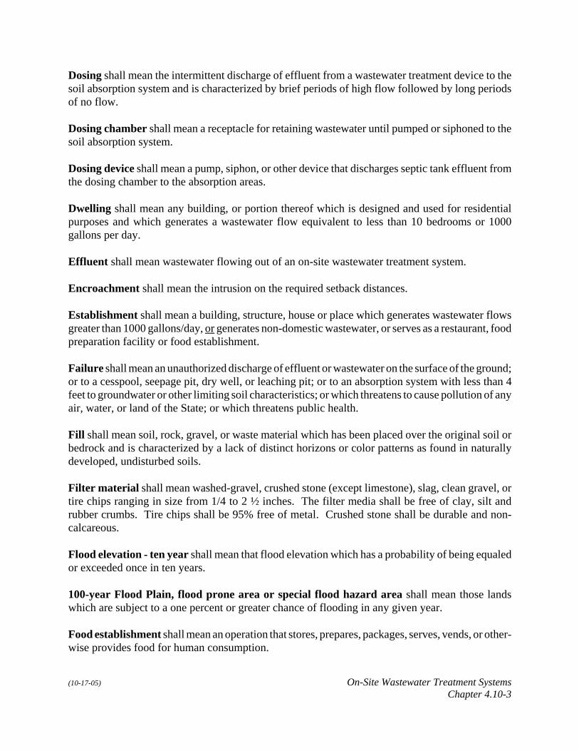
Dosing shall mean the intermittent discharge of effluent from a wastewater treatment device to thesoil absorption system and is characterized by brief periods of high flow followed by long periodsof no flow.
Dosing chamber shall mean a receptacle for retaining wastewater until pumped or siphoned to thesoil absorption system.
Dosing device shall mean a pump, siphon, or other device that discharges septic tank effluent fromthe dosing chamber to the absorption areas.
Dwelling shall mean any building, or portion thereof which is designed and used for residentialpurposes and which generates a wastewater flow equivalent to less than 10 bedrooms or 1000gallons per day.
Effluent shall mean wastewater flowing out of an on-site wastewater treatment system.
Encroachment shall mean the intrusion on the required setback distances.
Establishment shall mean a building, structure, house or place which generates wastewater flowsgreater than 1000 gallons/day, or generates non-domestic wastewater, or serves as a restaurant, foodpreparation facility or food establishment.
Failure shall mean an unauthorized discharge of effluent or wastewater on the surface of the ground;or to a cesspool, seepage pit, dry well, or leaching pit; or to an absorption system with less than 4feet to groundwater or other limiting soil characteristics; or which threatens to cause pollution of anyair, water, or land of the State; or which threatens public health.
Fill shall mean soil, rock, gravel, or waste material which has been placed over the original soil orbedrock and is characterized by a lack of distinct horizons or color patterns as found in naturallydeveloped, undisturbed soils.
Filter material shall mean washed-gravel, crushed stone (except limestone), slag, clean gravel, ortire chips ranging in size from 1/4 to 2 ½ inches. The filter media shall be free of clay, silt andrubber crumbs. Tire chips shall be 95% free of metal. Crushed stone shall be durable and non-calcareous.
Flood elevation - ten year shall mean that flood elevation which has a probability of being equaledor exceeded once in ten years.
100-year Flood Plain, flood prone area or special flood hazard area shall mean those landswhich are subject to a one percent or greater chance of flooding in any given year.
Food establishment shall mean an operation that stores, prepares, packages, serves, vends, or other-wise provides food for human consumption.

(10-17-05) On-Site Wastewater Treatment SystemsChapter 4.10-4
Freeboard shall mean the distance between the liquid level and the top of the septic tank or the topof the lagoon dike.
Gravelless system shall mean a chamber or pipe absorption system designed to be installed withoutfilter material.
Graywater shall mean all domestic waste excluding blackwater and including bath, lavatory,laundry, and sink waste except kitchen sink waste.
Grease trap shall mean a watertight tank for the collection and retention of grease which isaccessible for periodic removal of the contents.
Groundwater shall mean water occurring beneath the surface of the ground that fills availableopenings in rock or soil materials such that they may be considered saturated.
Holding tank shall mean a tank for storage of wastewater until it can be transported to a point forproper disposal.
Industrial waste shall mean wastewater not otherwise defined as domestic wastewater, includingthe runoff and leachate from areas that received pollutants associated with industrial or commercialstorage, handling, or processing.
Influent shall mean wastewater flowing into an on-site wastewater treatment system.
Inspector shall mean a certified professional holding a certificate issued by the NebraskaDepartment of Environmental Quality in the category of Inspector.
Journeyman Installer shall mean a certified professional holding a certificate issued by theNebraska Department of Environmental Quality in the category of Journeyman Installer.
Layout Specialist shall mean a certified professional holding a certificate issued by the NebraskaDepartment of Environmental Quality in the category of Layout Specialist.
Liner shall mean the material or substance used to line the bottom of a wastewater lagoon, sandfilter, wetlands cell, or other on-site wastewater treatment system so that percolation of liquidsthrough the soil is controlled.
Lot shall mean a parcel of land occupied or intended for occupancy by a use permitted in LincolnMunicipal Code Chapter 27 - Zoning Code.
Lot size shall mean the square footage or acreage area of a lot, excluding all area below the normalhigh water level of any surface water feature, all area within a ten-year flood elevation or that isdetermined by the Health Director to be subject to flooding, and all area within the right-of-way oreasement of a street, road, or access easement.

(10-17-05) On-Site Wastewater Treatment SystemsChapter 4.10-5
Master Installer shall mean a certified professional holding a certificate issued by the NebraskaDepartment of Environmental Quality in the category of Master Installer.
Non-community water supply system shall many any public water supply system that is not acommunity water system.
Non-standard on-site wastewater treatment system shall mean a system which does not meet therequirements of these design standards or generates over 1000 gallons per day.
NPDES shall mean a permit issued in accordance with the Nebraska Department of EnvironmentalQuality Title 119 - Rules and Regulations Pertaining to the Issuance of Permits Under the NationalPollutant Discharge Elimination System.
Observation hole shall mean an excavation, test pit, or auger boring, used to determine the soilprofile and conditions, or monitor the groundwater levels.
On-site wastewater treatment system shall mean any system of piping, treatment devices, or otherappurtenances that convey, store, treat, or dispose of domestic or non-domestic wastewater, but notincluding wastewater from a livestock waste control facility, on the property where it originates, oron nearby property under the control of the user, which system is not connected to a public sewersystem. An on-site wastewater treatment system begins at the end of the building drain. All systemsexcept septic systems are limited to a maximum size of 1000 gallons per day to be considered an on-site wastewater treatment system. The word “onsite” used in these Design Standards is equivalentto the word “on-site”.
Percolation rate shall mean the rate, usually expressed in minutes per inch, obtained frompercolation tests used in determining the amount of absorption area required.
Percolation test shall mean the determination of the suitability of an area for subsurface wastewatereffluent disposal by testing the rate at which the undisturbed soil in an excavated pit or hole ofstandard size will absorb liquid per unit of surface area.
Perforated pipe shall mean one type of distribution tile generally four inches in diameter with halfto three-fourths inch diameter perforations designed to distribute wastewater effluent.
Plastic limit shall mean the water content expressed as a percentage of the dry weight of soil atwhich the soil mass ceases to be plastic and becomes brittle.
Pollution shall mean the man-made or man-induced alteration of the chemical, physical, biological,or radiological integrity of water, land, air, or vegetation.
Private well shall mean a well which provides water supply to less than 15 service connections andregularly serves less than 25 individuals.

(10-17-05) On-Site Wastewater Treatment SystemsChapter 4.10-6
Professional Engineer shall mean a person licensed by the State of Nebraska as a ProfessionalEngineer.
Professional Geologist shall mean a person licensed by the State of Nebraska as a ProfessionalGeologist.
Public water supply system shall mean a water supply system for providing the public with waterfor human consumption through pipes or other constructed conveyances, if such system has at leastfifteen service connections or regularly serves an average of at least twenty-five individuals daily,at least sixty days per year. This definition shall include: a) any collection, treatment, storage, anddistribution facilities under control of the operator of such system and used primarily in connectionwith such system, and b) any collection or pretreatment storage facilities not under such controlwhich are used primarily in connection with such system.
Registered Environmental Health Specialist shall mean a person who has the educationalrequirements and experience in the field of environmental sanitation required by Nebraska RevisedStatues 71-3703 and is registered with the Nebraska Board of Registration for Environmental HealthSpecialists in accordance with Nebraska Revised Statues 71-3702 through 71-3715.
Repair shall mean the correction of a mechanical, electrical or minor structural defect in an existingonsite wastewater system component such as, but not limited to, sealing a crack in a tank lid,replacing a tank baffle, leveling a distribution box, replacing a building sewer pipe, or replacing acracked pipe between the septic tank and soil absorption system. Repair does not include replace-ment of tanks or soil absorption systems, extension or enlargement of soil absorption componentsand systems, replacement or distribution pipes, or covering or plugging holes in metal tanks.
Sand shall mean a soil texture composed by weight of at least 90% of soil particles ranging in sizebetween .05 and 2.0 mm or .002 inches and .08 inches.
Sandy soil shall mean the soil having the following textures: sands, fine sands, loamy fine sands,and loamy very fine sands.
Septic tank shall mean a watertight covered receptacle designed and constructed to receivewastewater from a building sewer, separate solids from liquids, digest organic matter, store digestedsolids through a period of detention, and allow the clarified liquid to discharge to a soil absorptionsystem.
Sewage shall mean any water carrying domestic waste exclusive of footing and roof drainage, fromany industrial, agricultural, or commercial establishment or any dwelling or any other structures.
Site shall mean the area bounded by the dimensions required for the proper location of the soilabsorption system.

(10-17-05) On-Site Wastewater Treatment SystemsChapter 4.10-7
Site Evaluator shall mean a certified professional holding a certificate issued by the NebraskaDepartment of Environmental Quality in the category of Site Evaluator.
Soil Evaluator shall mean a certified professional holding a certificate issued by the NebraskaDepartment of Environmental Quality in the category of Soil Evaluator.
Slope shall mean the ratio of vertical rise or fall to horizontal distance.
Sludge shall mean the accumulated settled solids deposited from wastewater and containing waterto form a semi-liquid mass.
Soil absorption system shall mean a drainfield, leaching area, or seepage bed including the effluentapplication/distribution system intended for the treatment of wastewater or disposal of effluent. Theabsorption system includes the infiltrative surface in the absorption trench and the soil between andaround the trenches.
Standard on-site wastewater treatment system shall mean a system which meets the requirementsof these design standards.
Surface waters shall mean all waters within the jurisdiction of this state, including all streams,lakes, ponds, impounding reservoirs, marshes, wetlands, watercourses, waterways, springs, canalsystems, drainage systems, and all other bodies or accumulations of water, natural or artificial,public or private, situated wholly or partly within or bordering upon the state. Impounded watersin this definition do not include areas designated by the Department as wastewater treatment orwastewater retention facilities or irrigation reuse pits.
Title 124 shall mean the Nebraska Department of Environmental Quality Title 124 - Rules andRegulations for the Design, Operation and Maintenance of On-site Wastewater Treatment Systems.
Wastewater shall mean the liquid and waterborne wastes derived from the ordinary living processesand of such character as to permit satisfactory disposal, without special treatment, into the publicsewer or by means of an on-site wastewater treatment system.
Wastewater lagoon shall mean a shallow body of water which meet the requirements of thesedesign standards.
Wastewater works shall mean facilities for collecting, transporting, pumping and treatingwastewater and the disposal of treated effluent and sludges.
Waters of the state shall mean all waters within the jurisdiction of this state, including all streams,lakes, ponds, impounding reservoirs, marshes, wetlands, water courses, waterways, wells, springs,irrigation systems, drainage systems and all other bodies or accumulations of water, surface orunderground, natural or artificial, public or private, situated wholly or partly within or borderingupon the state.

(10-17-05) On-Site Wastewater Treatment SystemsChapter 4.10-8
Section 2. APPLICATION OF DESIGN STANDARDS (Amended by Resolution A-83599, adopted 10-17-05).
A. A dwelling or establishment that generates wastewater shall have an on-site wastewatertreatment system in accordance with these design standards or be connected to a wastewaterworks.
B An on-site wastewater treatment system installed on or after the effective date of thesedesign standards shall meet all requirements of the design standards.
C. An existing on-site wastewater treatment system is subject to these design requirements if:1. It is causing or contributing to a public health or safety hazard, failing, or discharging
a prohibited discharge,2. It is being replaced, reconstructed, altered, or modified,3. There is an adverse change in use such as an increase in the number of bedrooms,
design flow, or waste strength,4. It begins receiving wastewater from a different dwelling or establishment than it was
originally constructed to serve,5. It begins receiving wastewater from a dwelling or establishment that is reconstructed
or replaced following an event such as fire that renders the structure unsuitable foroccupancy, or
6. The system owner creates or causes an encroachment on a setback distance by achange in a property line or construction of a new development feature such as awell, water line or foundation.
D. Basic repairs not requiring a repair permit (LMC 24.38.040) and maintenance can beperformed on an on-site wastewater treatment system that is functioning properly withoutbeing subject to these design standards.
E. A temporary modification to a failing on-site wastewater treatment system not meeting therequirements of these design standards may be performed without meeting these designstandards if the modification is to prevent a surface discharge or reduce a threat to publichealth. The temporary modification may operate for no more than thirty (30) days withoutDepartment approval.
F. A discharge of wastewater is prohibited:1. To surface water without a National Pollutant Discharge Elimination System
(NPDES) permit;2. To groundwater without Department approval; and3. To the land surface from a dwelling, establishment, building sewer, or on-site
wastewater treatment system without Department approval.
G. In implementing these design standards, the Department shall protect the public’s health,prevent nuisance conditions, prevent health and safety hazards, protect the quality of surfacewater and groundwater in the immediate vicinity of any proposed on-site wastewater

(10-17-05) On-Site Wastewater Treatment SystemsChapter 4.10-9
treatment system. In protecting the quality of the ground and surface water, the Departmentshall consider the following:1. The use classification of the surface water and groundwater (NDEQ Title 117 -
Nebraska Surface Water Quality Standards and Title 118 - Groundwater QualityStandards and Use Classification);
2. Vulnerability of surface water and groundwater to pollution;3. The beneficial uses existing or assigned to the surface waters and groundwaters.
Beneficial uses are those uses of surface waters and groundwaters as determinedthrough NDEQ Title 117 and NDEQ Title 118, respectively;
4. Characteristics of the on-site wastewater treatment system;5. Technical and socioeconomic factors; and6. Other appropriate site-specific factors.
H. In addition to the requirements of these design standards, all subsurface disposal systemshaving the capacity to accept sanitary waste generated by greater than 20 persons or the fluidflow is greater than 1000 gallons per day, or on-site wastewater treatment systems thatreceive non-domestic wastes may be subject to Nebraska Department of EnvironmentalQuality (NDEQ) Title 122 Rules and Regulations for Underground Injection and MineralProduction Wells.
I. Nothing in these design standards shall prevent more stringent local requirements from beingadopted.
J. Where applicable Nebraska Health & Human Services Title 178 NAC 12 - RegulationsGoverning Water Well Construction Pump Installation, and Water Well DecommissioningStandards and Title 179 NAC 2 - Regulations Governing Public Water Supply Systems mayrequire more stringent setback requirements.

(10-17-05) On-Site Wastewater Treatment SystemsChapter 4.10-10
Section 3. VARIANCE
A. Any person who owns or is in control of any on-site wastewater treatment system or propertyon which an on-site wastewater treatment system exists or is proposed may apply to theHealth Director for a variance from rules or design standards. The Director may grant suchvariance if he or she finds that:1. the proposed variance will not substantially reduce the capability or capacity of the
on-site wastewater treatment system to treat sewage;2. the discharges occurring or proposed to occur do not (or will not) endanger or tend
to endanger human health or safety or create or contribute to pollution of air, land orwater; and
3. compliance with the rules or design standards from which variance is sought wouldproduce serious hardship without equal or greater benefits to the public. In makingsuch findings the Health Director shall give due consideration to all facts andcircumstances bearing upon the reasonableness of the discharges involved includingbut not limited to:a. The character and degree of injury to or interference with the health and
physical property of the people;b. The risk, character and degree of environmental pollution; andc. The technical practicability and economic reasonableness of reducing or
eliminating the emissions or discharges resulting from such source.
B. No variance shall be granted until the Health Director has considered the relative interestsof the applicant, other owners of property likely to be affected by the discharges, and thegeneral public.
C. Any variance or renewal thereof shall be granted within the requirements of subsection (A)of this section, for time periods and under conditions consistent with the reasons therefore,and within the following limitations:1. If the variance is granted on the grounds that there is no practicable means known
or available for the adequate prevention, abatement, or control of the air, water, orland pollution involved, it shall be only until the necessary means for prevention,abatement, or control become known and available and subject to the taking of anysubstitute or alternate measures that the Health Director may prescribe;
2. If the variance is granted on the grounds that compliance with the particularrequirements or requirements from which variance is sought will necessitate thetaking of measures which, because of their extent or cost, must be spread over aconsiderable period of time, it shall be for a period not to exceed such reasonabletime as, in the view of the Health Director, is requisite for the taking of the necessarymeasures. A variance granted on the grounds specified in this section shall containa timetable for the taking of action in an expeditious manner and shall be conditionedon adherence to such timetable;

(10-17-05) On-Site Wastewater Treatment SystemsChapter 4.10-11
3. If the variance is granted on the ground that it is justified to relieve or preventhardship of a kind other than that provided for in sub-division (1) or (2) of thissubsection, it shall be for not more than one year.
D. Any variance granted pursuant to this section may be renewed on terms and conditions andfor periods which would be appropriate on initial granting of a variance. If a complaint ismade to the Health Director on account of the variance, no renewal thereof shall be grantedunless the Health Director finds that renewal is justified. No renewal shall be granted excepton application therefore. Any such application shall be made at least thirty (30) days priorto the expiration of the variance. Immediately upon receipt of an application for renewal theHealth Director shall give public notice of such application.
E. A variance or renewal shall not be a right of the applicant or holder thereof but shall be inthe discretion of the Health Director. The granting or denial of a variance or a renewal shallbe by final order of the Health Director.
F. Nothing in this section and no variance or renewal granted pursuant to this section shall beconstrued to prevent or limit the authority of the Health Director to cause abatement ofpublic health nuisance conditions or take legal action.
G. No variance shall be granted which will sanction any violation of state or federal statutes orregulations. All variance requests will be provided to NDEQ for their review and comment.
Section 4. PERMIT APPLICATION AND SITE EVALUATION(Amended by Resolution A-83599, adopted 10-17-05).
A. Each proposed site for the location of an on-site wastewater treatment system shall beevaluated by a professional engineer, registered environmental health specialist, layoutspecialist, Journeyman Installer, or Master Installer and the following information shall berecorded on application forms provided by the Department:1. The type, size, location, and elevation of the proposed system, clearly identified on
a scaled drawing of sufficient size which will include: the legal description andsurvey of the lot and immediate vicinity property lines, buildings, waters supplywells, buried water pipes and utility lines, the ordinary high water mark of lakes,rivers, streams, flood plain, reserve area and the location of the type of water supplywells within 1000 feet of the proposed on-site wastewater treatment system.
2. An appropriate scaled drawing of the on-site wastewater treatment system whichspecifies location, materials or construction, capacity, setbacks and constructiondetails.
3. Depth to the seasonal highest measured or estimated groundwater table and to thebedrock surface, if this depth is less than the depth of the seasonal high groundwatertable.
4. Direction of groundwater flow.5. Soil conditions, properties, and permeability.

(10-17-05) On-Site Wastewater Treatment SystemsChapter 4.10-12
6. Additional information may be required.
B. A new on-site wastewater treatment system shall not be installed in a designated ten-yearfloodplain or within the area of the ordinary high water mark of lakes, rivers, or streams.
C. The seasonal high water elevation of the groundwater table must be at least four feet belowthe bottom of the infiltrative surface of the soil absorption system in order to provideadequate filtration through the soil and avoid pollution of the groundwater. When availablethe following sources or types of information shall be used in determining the seasonal highwater elevation of the groundwater.1. U.S. Department of Agriculture Natural Resources Conservation Service soils maps
and soil interpretation records.2. Evaluation of soil color and the presence or absence of mottling.3. Evaluation of impermeable or semi-permeable soil layers.4. Measured water levels for any nearby test hole(s), observation well(s), or water
well(s).
D. Prior to construction of a development area where any on-site wastewater treatment systemis proposed on any lot, the owner shall submit an application on forms provided by theHealth Director and appropriate fees to the Health Director. The Health Director willreview the application and either approve or deny the use of on-site wastewater treatmentsystems for the development area based upon the ability of the applicant to meet these designstandards. The application shall be accompanied by information that complies with require-ments for Lincoln Municipal Code 26.15 Preliminary Plat and, in addition to therequirements stipulated in LMC 26.15.015(h)(2), shall show the reserve area required bythese design standards (Section 4(E)). Soil information shall include soil percolation tests,and soil borings or site excavations, conducted on a minimum of 25% of the lots, todetermine the soil characteristics and seasonal groundwater levels. The Health Director mayrequire additional soil testing, if, in his or her opinion, the information provided is notadequate to make a sound determination as to the suitability of the soils to support on-sitewastewater treatment systems.
E. All dwellings and establishments constructed after the effective date of these designstandards shall establish a reserve area to be used for a replacement on-site wastewatertreatment system which will meet the requirements of these design standards:1. The reserve area will be considered a part of the on-site wastewater treatment system
and all setback requirements will apply.2. Soil percolation test or soil analysis must be performed for the reserve area and
provided to the Health Director.

(10-17-05) On-Site Wastewater Treatment SystemsChapter 4.10-13
Section 5. SETBACK DISTANCES(Amended by Resolution A-83599, adopted 10-17-05).
A. The installation of a septic tank or holding tank and soil absorption, infiltrative orevaporative system is prohibited within the setback distances in Table 5.1.
Table 5.1 - Septic Tank, Holding Tank, and Soil Absorption Systems
Minimum Setback Distance in feet (meters)
Item Tanks Absorption, Infiltrative, andEvaporative Systems
Surface Water 50 ft. (15.2 m) 50 ft. (15.2 m)
Private Drinking Water Wells 50 ft. (15.2 m) 100 ft. (30.5 m)
Public Drinking Water Supply Wells:
Non Community System 50 ft. (15.2 m) 100 ft. (30.5 m)
Community System 500 ft. (152.4 m) 500 ft. (152.4 m)
Community System when a septicsystem or soil absorption system of >1000 gpd is proposed
500 ft. (152.4 m)Evaluated by professional
engineer for potential impact onthe well and submitted to the
Department for approval if lessthan 1000 ft.
All Other Water Wells: 50 ft. (15.2 m) 100 ft. (30.5 m)
Water Lines:
Pressure-Main 10 ft. (3.1 m) 25 ft. (7.6 m)
Pressure-Service Connection 10 ft. (3.1 m) 25 ft. (7.6 m)
Suction Lines 50 ft. (15.2 m) 100 ft. (30.5 m)
Property Lines Public Right-Of-Way Other property
15 ft (4.6 m)5ft (1.55 m)
15 ft. (4.6 m) 5ft. (1.55 m)
Foundations: (see “class” definition following Table 5.2)
Except Neighbors Foundation: Class 1* Class 2** Class 3***
15 ft (4.6 m)10 ft. (3.1 m)
7 ft. (2.1 m)
30 ft. (9.1 m)20 ft. (6.1 m)10 ft. (3.1 m)
Neighbors Foundation: Class 1* Class 2** Class 3***
25 ft. (7.6 m)20 ft. (6.1 m)15 ft. (4.6 m)
40 ft. (12.2 m)30 ft. (9.1 m)20 ft. (6.1 m)

(10-17-05) On-Site Wastewater Treatment SystemsChapter 4.10-14
B. The installation of a lagoon is prohibited within the setback distances in Table 5.2
Table 5.2 - Lagoons
Item Minimum Setback Distance - feet (meters)
Surface Water: Distance from High Water Mark 50 ft. ( 15.2 m )Private Drinking Water Wells: 100 ft. ( 30.5 m )Public Drinking Water Supply Wells: Non-Community 100 ft. ( 30.5 m ) Community 500 ft. (152.4 m )All Other Water Wells: 100 ft. (152.4 m )Water Lines: Pressure-Main 25 ft. ( 7.6 m ) Pressure-Service Connection 25 ft. ( 7.6 m ) Suction Line 100 ft. ( 30.5 m )Property Lines: 50 ft. ( 15.2 m )Trees: 50 ft. ( 15.2 m )Foundations: (see “class” definition at end of Table 5.2) Except Neighbors Foundation: Class 1 * 100 ft. ( 30.5 m ) Class 2 ** 100 ft. ( 30.5 m ) Class 3 *** 50 ft. ( 15.2 m ) Neighbors Foundation: Class 1 * 200 ft. ( 61.0 m ) Class 2 ** 200 ft. ( 61.0 m ) Class 3 *** 100 ft. ( 30.5 m )
*Class 1 Foundations: Full basements, or non-basement footing foundations and slab on grade for living quartersthat are lower in elevation from the on-site wastewater treatment system.
**Class 2 Foundations: Non-basement footing foundations, trailer houses and slab on grade living quarters that arehigher in elevation than the on-site wastewater treatment system.
***Class 3 Foundations: Structures using slab on grade construction and are not used as living quarters.
C. An on-site wastewater treatment system not located on the property owned by the personusing the system shall have a permanent easement for use and maintenance of the system onthe land on which the system resides.
(10-17-05) On-Site Wastewater Treatment SystemsChapter 4.10-15
D. The Health Director may require greater setback distances for approvable discharge systemsas necessary to protect the surface water and groundwater.
E. Setback distances for all other on-site wastewater treatment systems shall be determined bythe Health Director and be established to protect public health and the environment.
F. Construction or relocation of a foundation, well, water line, surface water feature, orproperty line within the setback distances listed in Table 5.1 or Table 5.2, of any onsitewastewater system or area reserved for a replacement soil absorption system is prohibited,except that the Health Director may approve a variance for encroachment of a foundationwithin the minimum setback distances to system components upon submittal of a foundationconstruction plan and a letter from a professional engineer stating that he or she hasevaluated the proposed construction plan and in his or her professional opinion, theencroachment will not have any detrimental effect on the structural integrity of thefoundation or system components, or on the proper function and operation of the systemcomponents, or on the ability to maintain or replace any of the system components.
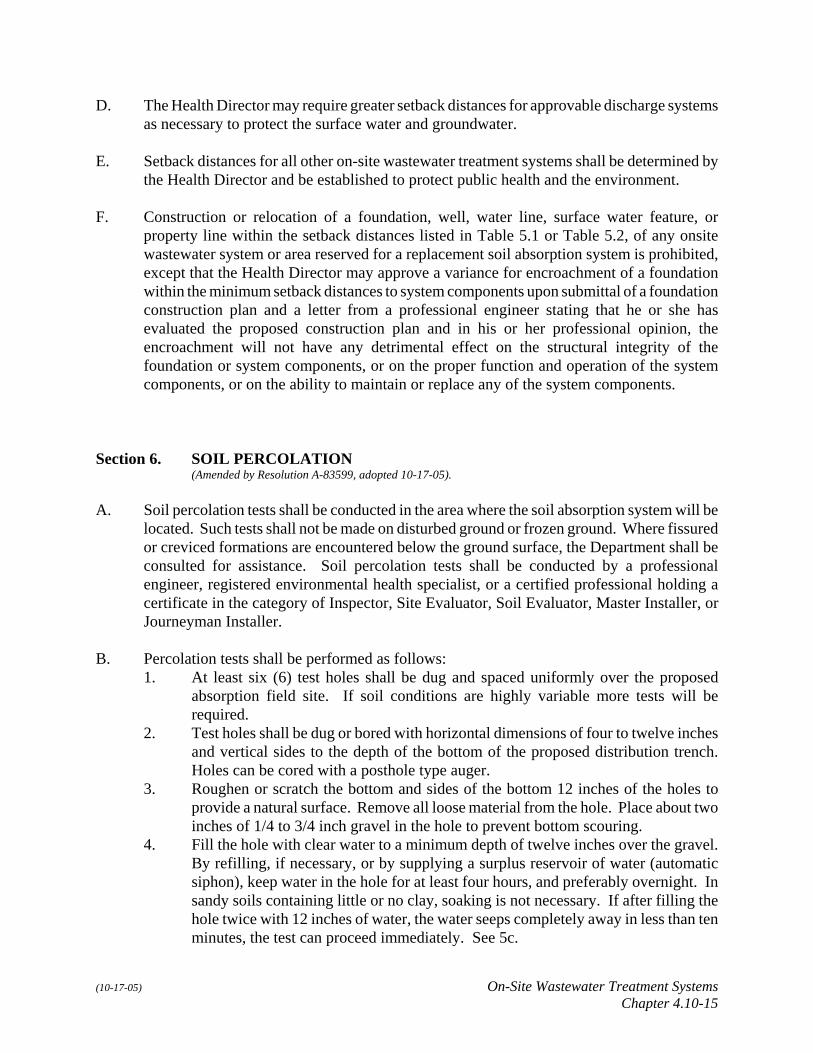
Section 6. SOIL PERCOLATION (Amended by Resolution A-83599, adopted 10-17-05).
A. Soil percolation tests shall be conducted in the area where the soil absorption system will belocated. Such tests shall not be made on disturbed ground or frozen ground. Where fissuredor creviced formations are encountered below the ground surface, the Department shall beconsulted for assistance. Soil percolation tests shall be conducted by a professionalengineer, registered environmental health specialist, or a certified professional holding acertificate in the category of Inspector, Site Evaluator, Soil Evaluator, Master Installer, orJourneyman Installer.
B. Percolation tests shall be performed as follows:1. At least six (6) test holes shall be dug and spaced uniformly over the proposed
absorption field site. If soil conditions are highly variable more tests will berequired.
2. Test holes shall be dug or bored with horizontal dimensions of four to twelve inchesand vertical sides to the depth of the bottom of the proposed distribution trench.Holes can be cored with a posthole type auger.
3. Roughen or scratch the bottom and sides of the bottom 12 inches of the holes toprovide a natural surface. Remove all loose material from the hole. Place about twoinches of 1/4 to 3/4 inch gravel in the hole to prevent bottom scouring.
4. Fill the hole with clear water to a minimum depth of twelve inches over the gravel.By refilling, if necessary, or by supplying a surplus reservoir of water (automaticsiphon), keep water in the hole for at least four hours, and preferably overnight. Insandy soils containing little or no clay, soaking is not necessary. If after filling thehole twice with 12 inches of water, the water seeps completely away in less than tenminutes, the test can proceed immediately. See 5c.

(10-17-05) On-Site Wastewater Treatment SystemsChapter 4.10-16
5. Percolation rate measurements should be made on the day following the saturationprocess, except in sandy soils.a. If the water remains in the test hole after overnight saturation, adjust the
water depth to a minimum of six inches over the gravel. From a fixedreference point, measure the drop in water level during a 30-minute period.
b. If no water remains in the hole after overnight saturation, add clear water toa depth of six inches over the gravel. From a fixed referenced point, measurethe drop in water level at 30 minute intervals over a four hour period,refilling the hole to a depth of six inches over the gravel after each 30-minuteperiod. The drop which occurs during the final 30-minute period must beused to calculate the percolation rate.
c. In sandy soils, or in other soils in which the first six inches of water seepsaway in less than 30 minutes even after the overnight swelling period, thetime interval between measurements can be taken as ten minutes, refilling thehole to a depth of 6 inches as necessary after each interval, six testmeasurements will be made at ten minute intervals. The drop that occursduring the final ten minutes must be used to calculate the percolation rate.
d. Soils with moderately slow permeability and/or containing greater than 30%clay in the testing zone will require several days saturation when the soil isdry to achieve thorough swelling of the soil prior to making measurements.
6. The percolation test data shall be recorded and maintained on the premises andsubmitted to the Department as required in Section 4.
7. Other methods of determining the percolation rate may be approved by theDepartment if the method is recognized as providing accurate and consistent results.
C. To obtain the percolation rate of a test hole (the average time in minutes for water to fall oneinch), divide the number of minutes elapsed by the drop in inches. An average percolationrate for the entire field should be determined from the percolation rate of each of the testholes. If tests in the area vary more than 20 minutes/inch, variations in soil type areindicated. Under these circumstances, percolation rates shall not be averaged and the designshall be based on the slowest rate.
D. Site Acceptability Based on Soil Conditions.1. Soil is unsuitable for a soil absorption system if the percolation rate is faster than 5
minutes per inch, or is slower than 60 minutes per inch.a. Soil with percolation rates faster than 5 minutes per inch are acceptable if a
12 inch thick loamy sand soil liner with a percolation rate of 15 to 20 minutesper inch is installed in the trench in accordance with Section 14. A trench isthen sized on this soil liner’s percolation rate.
2. A soil absorption system shall not be installed if the percolation rate is outside therange defined above unless designed by a professional engineer and a constructionpermit is issued by the Health Director.
3. Any alternative non-standard on-site wastewater treatment system which is proposedto accommodate unsuitable soil conditions must be designed by a professionalengineer and approved by the Health Director.

(10-17-05) On-Site Wastewater Treatment SystemsChapter 4.10-17
E. The Health Director may require verification of percolation rates or perform percolation testson the property when submitted results are inconsistent with other known data.
Section 7. SEPTIC TANK; CONSTRUCTION: MATERIALS USED
A. A septic tank shall be constructed of materials not subject to excessive corrosion or decayand shall be watertight. Concrete, concrete blocks, fiber reinforced plastic (FRP), highdensity plastic, and fiberglass are acceptable.1. When precast and cast in place reinforced concrete tanks are used they shall be
properly cured and of watertight construction.2. All concrete interior surfaces exposed to air shall be coated with a bitumastic or
similar compound beginning at an elevation 3 inches below the normal operatinglevel to minimize corrosion.
3. Concrete block tanks shall be laid on a solid foundation and mortar joints shall befilled. The interior of the tank shall be surfaced with two one-fourth inch thick coatsof portland cement, sand plaster, or shall be coated with a bitumastic material.Special attention shall be given to job-built tanks to insure water tightness.
4. The tank shall be designed to withstand soil pressures when empty and not collapseor undergo excessive deflection which would prevent the proper operation of thesystem, crack or distort components of the system such as the baffles, prevent propersealing of lids over manholes and inspection ports, or reduce the volume of thesystem.
5. All septic tanks shall be permanently marked to specify the capacity in gallons,manufacturer, and the manufacturer’s address. The gallon and manufacturingidentification label shall be located next to the manhole towards the inlet side.
Section 8. SEPTIC TANK DESIGN(Amended by Resolution A-83599, adopted 10-17-05).
A. All septic tanks regardless of material or method of construction shall conform to thefollowing criteria shown in figures 8.1, 8.2, 8.3, and 8.4.1. The depth from the invert of the outlet to the floor of the tank (liquid depth) of any
septic tank or compartment thereof shall not be less than 42 inches and a liquid depthgreater than 78 inches shall not be considered in determining tank capacity. Thediameter of a septic tank shall not be less than 60 inches and the length shall beapproximately two to three times the width.
2. No tank or compartment thereof shall have an inside horizontal dimension less than24 inches.
3. Inlet and outlet connections of the tank shall be provided with baffles. See Figure8.5.
4. The space in the tank between the liquid surface and the top of the inlet and outletbaffles shall be not less than 20 percent of the total required liquid capacity, exceptthat in horizontal cylindrical tanks this space shall be not less than 15 percent of thetotal required liquid capacity.
(10-17-05) On-Site Wastewater Treatment SystemsChapter 4.10-18
5. Inlet and outlet baffles shall be constructed of acid resistant concrete, acid resistantfiberglass, or plastic.
6. Sanitary tees shall be affixed to the inlet or outlet pipes with a permanent waterproofadhesive. Baffles shall be integrally cast with the tank, affixed with a permanentwaterproof adhesive, or affixed with stainless steel connectors top and bottom.
7. The inlet baffle shall extend at least 6 inches but not more than 20 percent of the totalliquid depth below the liquid surface and at least one inch above the crown of theinlet sewer.
8. The outlet baffle and the baffles between compartments shall extend below the liquidsurface a distance equal to 40 percent of the liquid depth except that the penetrationof the indicated baffles or sanitary tees for horizontal cylindrical tanks shall be 35percent of the total liquid depth. They also shall extend above the liquid surface asrequired in Section 8(4). In no case shall they extend less than six inches above theliquid surface.
9. There shall be at least 1 inch between the underside of the top of the tank and thehighest point of the inlet and outlet devices.
10. The inlet invert shall be not less than 2 inches above the outlet invert.11. The inlet and outlet shall be located opposite each other along the axis of maximum
dimension and shall be constructed of noncorrosive materials. The horizontaldistance between the nearest points of the inlet and outlet devices shall be at least 4feet.
12. Sanitary tees shall be at least 4 inches in diameter. Inlet baffles shall be located noless than 6 inches or no more than 12 inches measured from the end of the inlet pipeto the nearest point on the baffle. Outlet baffles shall be located 6 inches measuredfrom beginning of the outlet pipe to the nearest point on the baffle.
13. Access to the septic tank shall be as follows:a. There shall be one or more access manholes at least 12 inches in diameter
and located within six feet of all walls of the tank. The manhole shall extendthrough the top of the tank to a point within 12 inches but at least six inchesbelow grade. Each manhole shall have a cover. The manhole cover shall becovered with at least six inches of earth. A riser as described in Section 9(c)may also be provided.
b. There shall be an inspection pipe at least 6 inches diameter or a manhole overboth the inlet and outlet devices.
14. Compartmentation of single tanks.a. Septic tanks larger than 3000 gallons and fabricated as a single unit shall be
divided into two or more compartments.b. When a septic tank is divided into two compartments, not less than one-half
nor more than two-thirds of the total volume shall be in the firstcompartment.
c. When a septic tank is divided into three or more compartments, one-half ofthe total volume shall be in the first compartment and the other half equallydivided in the other compartments.
d. Connections between compartments shall be baffled so as to obtain effectiveretention of scum and sludge. The submergence of the inlet and outletbaffles of each compartment shall be as specified in Section 8(7) and (8).

(10-17-05) On-Site Wastewater Treatment SystemsChapter 4.10-19
e. Adequate venting shall be provided between compartments by baffles or byan opening of at least 50 square inches near the top of the compartment wall.
f. Adequate access to each compartment shall be provided by one or moremanholes.
15. Multiple Tanksa. Where more than one tank is used to obtain the required liquid volume, the
tanks shall be connected in series.b. No more than four tanks in series shall be used to obtain the required liquid
volume.c. The first tank shall be no smaller than any subsequent tanks in series.

(10-17-05) On-Site Wastewater Treatment SystemsChapter 4.10-20

(10-17-05) On-Site Wastewater Treatment SystemsChapter 4.10-21
DIMENSIONS
A 0.15 Diameter DIA 60 inch Minimum Inside Diameter
B 6 inch minimum 0.2 D Maximum D 0.79 Diameter
C 0.35 D to nearest inch L 2 to 3 times the diameter

(10-17-05) On-Site Wastewater Treatment SystemsChapter 4.10-22
Baffle Notation Measurement in Inches
A $1
B Inlet $2
C Inlet $6 but not more than 20% of tank depthOutlet $6 but not more than 40% for square tanksand 35% for round tanks
D Inlet $6 but #12Outlet = 6
E $6

(10-17-05) On-Site Wastewater Treatment SystemsChapter 4.10-23
Section 9. PLACEMENT OF SEPTIC TANK
A. The septic tank shall be bedded with at least six (6) inches of sand or fine gravel where rockor other undesirable conditions are encountered. The tank shall be placed level. Whereexcavation is required the hole shall be sufficiently large to permit placement of the tank.Backfilling the excavation for septic tanks shall be done in layers with sufficient tamping toavoid settling. Backfill material shall be free of large stones and debris.
B. A tank located in a high water table or within the 100-year flood plain shall be properlysecured or ballasted. The elevation of the flood plain cannot be higher than one foot belowthe top of the tank.
C. The manhole shall extend to a point within 12 inches and no closer than 6 inches of finishedgrade. A riser larger than the manhole extending to the surface, to a point at, or at leastwithin 6 inches of finished grade is also recommended. A cover shall be provided for theriser.
D. The inspection pipe shall extend through the cover and be capped flush or above finishedgrade.
Section 10. SEPTIC TANK CAPACITY
A. “Dwellings” - The liquid capacity of a septic tank serving a dwelling shall be based on thenumber of bedrooms served. For three or less bedrooms, an adequate septic tank capacityshall be one thousand gallons. For each additional bedroom two hundred fifty gallons shallbe added. Table 10.1 may be used to determine capacities.1. For ten or more bedrooms the septic tank shall be sized under the category of
“Establishments.”2. For multiple dwellings connected to a single tank, one additional bedroom capacity
must be added for each dwelling connected. Table 10.2 may be used for sizing.
B. “Establishments” - The liquid capacity of a septic tank serving an establishment other thana dwelling shall be at least equal to 1125 gallons plus 0.75 times the design flow in gallonsper day (gpd) for flows over 1500 gpd. For flows less than 1500 gpd, 1.5 times the designflow may be used but a minimum of a 1000 gallon tank is required.
C. For design flows greater than 2000 gpd, the installation of a two-compartment septic tankor two septic tanks installed in a series is required.
D. The tank capacity required for septic systems serving high strength, high temperature orinhibitors in wastewater such as food establishments, camper dump stations, laundry mats,and butcher shops or other similar facilities shall be doubled.

(10-17-05) On-Site Wastewater Treatment SystemsChapter 4.10-24
Table 10.1 Septic Tank Sizing for a Single Dwelling
Number ofBedrooms
One DwellingDesign Flow in
Gallons per DaySeptic Tank Size
In Gallons
Dwelling withWhirlpool Bath,
Septic Tank Size inGallons
1 200 1000 1000
2 300 1000 1000
3 400 1000 1250
4 500 1250 1500
5 600 1500 1750
6 700 1750 2000
7 800 2000 2250
8 900 2250 2500
9 1000 2500 2750
10 1100 Establishment Establishment
Table 10.2 Equivalent Septic Tank Sizing in Multiple Dwellings
TotalBedrooms
SingleFamily
DwellingTwo-Units Three-Units Four-Units Five-Units
1 1 - - - -2 2 3 - - -3 3 4 5 - -4 4 5 6 7 -5 5 6 7 8 96 6 7 8 9 Establishment7 7 8 9 Establishment Establishment8 8 Establishment Establishment Establishment Establishment9 9 Establishment Establishment Establishment Establishment
Add all of the bedrooms for the combined dwelling units and find that number in column 1. Afterfinding the number of bedrooms in column 1 move to the column that has the number of unitsconnected together and select the equivalent size. Use this number in Table 10.1 as the number ofbedrooms to size the septic tank.

(10-17-05) On-Site Wastewater Treatment SystemsChapter 4.10-25
E. For the purpose of this section, “capacity” shall be the volume as measured by thedimensions below the bottom of the outlet.
Section 11. HOLDING TANK
A. For dwellings, a holding tank shall have a minimum capacity of 1,000 gallons for two orfewer bedrooms plus 300 gallons for each additional bedroom.
B. For establishments, a holding tank shall have a minimum capacity of at least five times thedaily flow but never less than 1,000 gallons.
C. Holding tanks shall be equipped with an alarm or visible float that indicates that tank is 90percent full.
Section 12. GREASE TRAP
A. An external grease trap must be installed for all food establishments.1. Restaurants and establishments involved in food preparation that are replacing or
modifying their on-site wastewater treatment system may install an additional septictank in the waste line in lieu of a grease trap provided the following conditions aremet:a. The restaurant or establishment was constructed before the effective date of
these design standards;b. The current kitchen and blackwater waste streams are not separated;c. The additional septic tank is sized following Section D below; andd. The additional tank is placed in series with other tanks and complies with
Section 8(15).
B. If an external grease trap is used it shall be constructed of materials and installed asprescribed in LMC 24.10 Lincoln Plumbing Code.1. Blackwater other than kitchen waste shall not be connected to a grease trap.2. All wastewater from the kitchen operation shall be connected to the external grease
trap. The effluent from the grease trap shall connect to the inlet line of the septictank.
C. Operation and Maintenance1. Grease traps shall be operated properly and cleaned regularly to prevent the escape
of appreciable quantities of grease.2. Solvents, enzymes, or other chemicals or physical agents which may liquify grease,
including heat or hot water exceeding 1800F, shall not be used or applied.

(10-17-05) On-Site Wastewater Treatment SystemsChapter 4.10-26
D. Sizing of Grease Traps1. A grease trap shall provide twenty-four hours of detention time for the average daily
flow.2. The minimum capacity of any grease trap shall be 750 gallons.
Section 13. SOIL ABSORPTION SYSTEM
A. A soil absorption system is the part of the on-site wastewater treatment system which utilizesthe soil to further treat and dispose of effluent from an on-site wastewater treatment systemin a manner that does not result in a point source discharge and does not create a nuisance,health hazards, or ground or surface water pollution.
B. Two types of soil absorption systems are considered acceptable: absorption trenches andseepage beds.
Section 14. DESIGN AND CONSTRUCTION OF SOIL ABSORPTION SYSTEM(Amended by Resolution A-83599, adopted 10-17-05).
A. The bottom of trenches and beds shall be at least four feet above the seasonal highgroundwater table. If a water table is not present then the bottom of the trench shall be atleast four feet above the bedrock or other barrier layer.
B. A soil absorption system shall not be installed in fill, except when the fill material is sand,or when the bottom 12 inches or more of the trench or bed is located in undisturbed nativesoil below the fill. When constructing a system in sand fill, sufficient time shall be allowedafter placement of the fill, or sufficient compaction effort applied to the fill to preventsettlement after the system is installed.
C. When installing a trench or bed in soil that has a percolation rate faster than 5 minutes perinch, a 12 inch thick loamy sand soil liner with a percolation rate of 15 to 20 minutes perinch shall be installed in the trench or bed. The liner shall cover the bottom of the trench orbed and extend up the sidewalls a minimum of nine inches for filter material absorptionsystems, to the top of the slotted sidewalls in gravelless chamber systems, or to the top ofthe pipe in gravelless pipe systems. The soil absorption area shall be sized on this soil liner’spercolation rate.
D. Trenches and beds shall not be more than 100 feet in length unless it is installed using anapproved method or instrument to insure that the trench is level. If an approved method orinstrument is used to assure the trench is level, then trenches can be up to 150 feet in lengthfor gravity systems. Pressure systems are not restricted in length when an approved methodor instrument is used to insure that the system is level.
E. The bottom of the trench or bed excavation shall be level.

(10-17-05) On-Site Wastewater Treatment SystemsChapter 4.10-27
F. The bottom and sides of the soil absorption system to the top of the filter material shall beexcavated in such a manner as to leave the soil in a natural, unsmeared, and uncompactedcondition. Excavation shall be made only when the soil moisture content is at or less thenthe plastic limit. The bottom and sides of the soil absorption system may be required to beroughened, scratched or otherwise modified to assure absorption.
G. When the percolation rate is slower than 10 minutes per inch, excavation equipment or othervehicles shall not be driven on the soil absorption area.
H. The distribution pipes shall be laid level or on a uniform slope away from the distributiondevice of no more than four inches per 100 feet.
I. Distribution pipes in beds shall be uniformly spaced no more than 5 feet apart and not morethan 30 inches from the side walls of the beds.
J. The trenches or beds shall be backfilled and crowned above the finished grade to allow forsettling. The top six inches of soil shall have the same texture and density as the adjacentsoil.
K. The minimum depth of cover over the distribution pipes shall be at least eight inches. Themaximum depth of cover over the distribution pipes shall be no more than 36 inches.
L. No parking area, driveway or impermeable surface or cover shall be installed, created, orlocated over or within five feet horizontally of the soil absorption system.
M. Gravity Distribution:1. When a soil absorption system is located in sloping ground from 0 to 3%, septic tank
effluent may be distributed to the soil absorption system by either a distribution box,drop box or a header pipe.
2. A soil absorption system in sloping ground with greater than 3% slope shall use adrop box or pressure distribution:a. The bottom of each trench shall be level.b. The absorption trenches shall follow the ground surface contours so that
variations in trench depth are minimized.c. When ground slope is less than 10%, there shall be a minimum of 4 feet of
undisturbed soil between adjacent trenches and between the septic tanks andthe nearest trench. When ground slope is 10% to 20%, there shall be aminimum of 6 feet of undisturbed earth between adjacent trenches andbetween the septic tanks and the nearest trench. When the slope exceeds20%, there shall be a minimum of 10 feet of undisturbed soil betweenadjacent trenches and between the septic tanks and the nearest trench.
N. Distribution box: Septic tank effluent may be distributed by a distribution box. Thedistribution box may be built as an integral part of the septic tank or may be a separate unitset on solid ground and anchored in the drainfield.

(10-17-05) On-Site Wastewater Treatment SystemsChapter 4.10-28
1. The distribution box shall be set level and arranged so that effluent is evenlydistributed to each distribution line.
2. Each distribution line shall connect individually to the distribution box.3. The pipe connecting the distribution box to the distribution line shall be of a tight
joint construction laid on undisturbed earth or properly bedded throughout its length.4. Distribution boxes shall be constructed of a durable, watertight, non-corrosive
material. They shall be designed to accommodate the necessary distribution lines.5. Distribution boxes shall be provided with a minimum 12-inch diameter opening
which will serve as a ready access for inspection, cleaning, and general maintenance.6. The inverts of all outlets shall be at the same elevation as measured from a liquid
surface in the bottom of the box.7. The inlet invert shall be at least one inch above the outlet inverts.8. The outlet inverts shall be at least four inches above the distribution box floor.9. When septic tank effluent is delivered to the distribution box by pump, either a baffle
wall shall be installed in the distribution box or the pump discharge shall be directedagainst a wall or side of the box on which there is no outlet. The baffle shall besecured to the box and shall extend one inch above the crown of the inlet flow line.
O. Header pipe: If a header pipe is used the following criteria shall be observed:1. Header pipe shall have a minimum diameter of 4 inches.2. When a header pipe is used, there shall be an equal number of distribution lines
spaced evenly on both sides of the junction of the leader to the header.3. The header pipe shall be laid level with direct watertight connections to each drain
field line and the septic tank outlet pipe. The header shall be encased in filtermaterial.
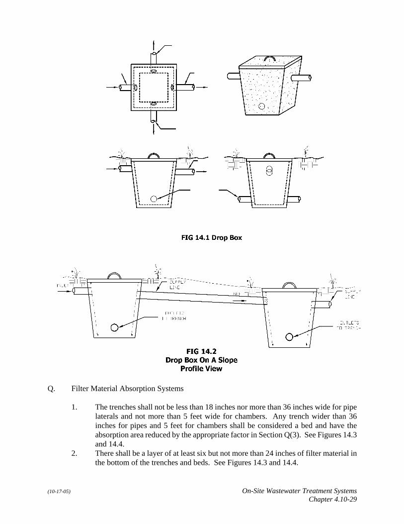
P. Drop box (see Figures 14.1 and 14.2): When drop boxes are used the following criteria shallbe followed:1. The drop box shall be watertight and constructed of durable materials not subject to
excessive corrosion or decay.2. The invert of the inlet pipe shall be at least one inch higher than the invert of the
outlet pipe to the next trench.3. The invert of the outlet pipe to the next trench shall be at least two inches higher than
the invert of the outlet pipe of the trench in which the box is located.4. When septic tank effluent is delivered to the drop box by a pump, the pump
discharge shall be directed against a wall or side of the box on which there is nooutlet.
5. The drop box shall have a removable cover either flush or above finished grade orcovered by more than six inches of soil.
(10-17-05) On-Site Wastewater Treatment SystemsChapter 4.10-29
Q. Filter Material Absorption Systems
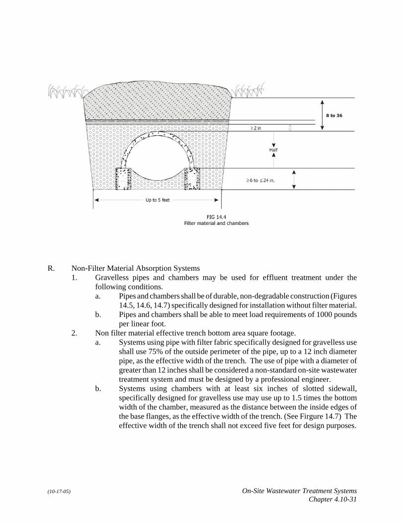
1. The trenches shall not be less than 18 inches nor more than 36 inches wide for pipelaterals and not more than 5 feet wide for chambers. Any trench wider than 36inches for pipes and 5 feet for chambers shall be considered a bed and have theabsorption area reduced by the appropriate factor in Section Q(3). See Figures 14.3and 14.4.
2. There shall be a layer of at least six but not more than 24 inches of filter material inthe bottom of the trenches and beds. See Figures 14.3 and 14.4.

(10-17-05) On-Site Wastewater Treatment SystemsChapter 4.10-30
3. Distribution pipes, gravity distributiona. Distribution pipes used in trenches or beds for gravity flow distribution shall
be at least four inches in diameter and constructed of sound and durablematerial not subject to corrosion or decay or to loss of strength undercontinuously wet conditions. When open joint tile is used, the tile sectionsshall be spaced not less than 1/4 inch nor more than 1/2 inch apart.
b. Perforated pipe used for wastewater distribution pipes shall have one or morerows of holes of no less than one-half inch in diameter and not more than 3/4inch in diameter spaced no more than 36 inches apart. Holes shall be spacedto prevent failure of pipe due to loads. Distribution pipes shall have a loadbearing capacity of more than 1000 pounds per linear foot.
c. Half moon concrete or plastic tile may be used for wastewater distributionand shall be placed in trenches resting on concrete blocks suitably placedbefore filter material is added unless specifically designed to be selfsupporting on the gravel bed with an appropriate supporting foot. See Figure14.4
4. The filter material shall completely encase the disposal pipes and chambers to adepth of at least two inches. See Figures 14.3 and 14.4.
5. The filter material shall be covered with untreated building paper or a two-inch layerof hay or straw or similar, approved permeable materials. See Figures 14.3 and 14.4.
(10-17-05) On-Site Wastewater Treatment SystemsChapter 4.10-31
R. Non-Filter Material Absorption Systems1. Gravelless pipes and chambers may be used for effluent treatment under the
following conditions.a. Pipes and chambers shall be of durable, non-degradable construction (Figures
14.5, 14.6, 14.7) specifically designed for installation without filter material.b. Pipes and chambers shall be able to meet load requirements of 1000 pounds
per linear foot.2. Non filter material effective trench bottom area square footage.
a. Systems using pipe with filter fabric specifically designed for gravelless useshall use 75% of the outside perimeter of the pipe, up to a 12 inch diameterpipe, as the effective width of the trench. The use of pipe with a diameter ofgreater than 12 inches shall be considered a non-standard on-site wastewatertreatment system and must be designed by a professional engineer.
b. Systems using chambers with at least six inches of slotted sidewall,specifically designed for gravelless use may use up to 1.5 times the bottomwidth of the chamber, measured as the distance between the inside edges ofthe base flanges, as the effective width of the trench. (See Firgure 14.7) Theeffective width of the trench shall not exceed five feet for design purposes.

(10-17-05) On-Site Wastewater Treatment SystemsChapter 4.10-32

(10-17-05) On-Site Wastewater Treatment SystemsChapter 4.10-33
S. Absorption Trench Sizing:1. The required square footage for absorption trenches for a dwelling shall be
determined by Table 14.1 when a percolation test was performed.
Table 14.1Perc Ratein minutesper inch
1Bedroom200 gpd
2Bedroom300 gpd
3Bedroom400 gpd
4Bedroom500 gpd
5Bedroom600 gpd
6Bedroom700 gpd
7Bedroom800 gpd
8Bedroom900 gpd
9Bedroom1000 gpd
<5 Systems must be designed with a 12 inch loamy sand liner that would have a percolation rate of 15 to 20 minutesper inch and shall be designed at the 11-20 minute per inch level
5-10 165 330 495 660 825 990 1155 1320 1485
11-20 210 420 630 840 1050 1260 1470 1680 1890
21-30 250 500 750 1000 1250 1500 1750 2000 2250
31-40 275 550 825 1100 1375 1650 1925 2200 2475
41-50 330 660 990 1320 1650 1980 2310 2640 2970
51-60 350 700 1050 1400 1750 2100 2450 2800 3150
>60 Systems must be designed by a professional engineer. Construction Permit Needed.
2. The required square footage for absorption trenches for establishments shall bedetermined by the following equation: square footage = design flow (gpd) ÷ (5÷/percolation (min/in)); where design flow is in gallons per day and percolation rate is inminutes per inch.
3. Absorption area for a bed shall be calculated by determining the required squarefootage for a trench and multiplying the area by the factor from Table 14.2.
Table 14.2Absorption Bed Multiplication Factor
Width of Bed in feet Factor
>3 to 10 1.25
>10 to 15 1.33
>15 to 30 1.50
>20 Unacceptable
T. Dosing.1. Dosing is recommended for all systems and shall be provided when the design
wastewater flow requires more than 500 linear feet of distribution line. When thedesign wastewater flow requires more than 1,000 linear feet of distribution line, theabsorption field shall be divided into two equal portions and each half dosedalternately, not more than four times per day.
(10-17-05) On-Site Wastewater Treatment SystemsChapter 4.10-34
2. Dosing may be accomplished by either pumps or siphons. Each side of the systemshall be dosed not more than four times per day. The volume of each dose shall bethe greater of the daily wastewater volume divided by the daily dosing frequency, oran amount equal to approximately 3/4 of the internal volume of the distribution linesbeing dosed (approximately 0.5 gallons or 1.89 L per linear foot of 4-inch pipe.)
Section 15. MAINTENANCE OF SEPTIC SYSTEMS AND LAGOONS
A. The owner of any septic tank or his agent shall regularly inspect and arrange for the removaland sanitary disposal of septage from the tank whenever the top fo the sludge layer is lessthan 12 inches below the bottom of the outlet baffles or whenever the bottom of the scumlayer is less than three inches above the bottom of the outlet baffle.
B. Disposal of septage shall be in accordance with Federal, State and local rules andregulations.
C. The owner of a lagoon shall inspect, operate and maintain the lagoon in the followingmanner:1. The lagoon shall be maintained with a minimum of two feet of liquid depth. Care
shall be taken to pump additional water to offset evaporation loss during hot weather.2. The lagoon area shall be mowed to keep grass and other plants at 6 inches or less in
height on the lagoon slopes and top of dike.3. The lagoon shall be operated to prevent the liquid level from encroaching on the one
foot freeboard requirement of the lagoon.4. Solids will be removed from the lagoon if needed and disposed of in accordance with
federal, state and local regulations.
D. To prevent soil erosion, all areas above the planned waterline and outside the lagoon whichwere disturbed during construction shall be seeded or sodded. Short grasses are preferredand shall be mowed to prevent overhanging vegetation. Alfalfa or similarly long rootedgrasses which might damage the integrity of the of the lagoon shall not be used. Novegetation other than short grasses shall extend above the top of the dike within a fifty footradius of the lagoon, including trees, weeds and brush.

(10-17-05) On-Site Wastewater Treatment SystemsChapter 4.10-35
Section 16. TYPE OF WASTE
A. The type of waste which can be directed to an on-site wastewater treatment system shall belimited to domestic wastewater. The following wastes are prohibited from entering an on-site wastewater treatment system unless specifically approved by the Health Director.1. Cooling water, groundwater infiltration, discharge from roof drains, discharge from
foundation tile drains, swimming pool water and wastewater, or other clear waterdischarges.
2. Hazardous waste: Any chemical substance or material, gas, solid, or liquiddesignated as hazardous in accordance with NDEQ Title 128 even in quantities lessthan regulated amounts.
3. Toxic substances: Toxic substances shall include antifreeze, oil, oil based or waterbased paint, gasoline, pesticides (insecticides and herbicides), solvents, brake fluid,transmission fluid, steering fluid, acids, and bases. Those pollutants or combinationof pollutants or disease causing agents, which after discharge and upon exposure,ingestion, inhalation, or assimilation into any organism, either directly from theenvironment or indirectly by ingestion through food chains, will on the basis ofinformation available to the Department cause either death, disease, behavioralabnormalities, cancer, genetic mutations, physiological malfunctions (includingmalfunction in reproduction), or physical deformations on such organism or itsoffspring.
Section 17. ABANDONMENT OF SEPTIC TANK AND LAGOON SYSTEMS
A. Whenever the use of a septic tank system is discontinued following the connection to asanitary sewer or following condemnation or demolition of a building or property or due tothe construction of another on-site wastewater treatment system, the septic tank system shallbe abandoned within 30 days and any further use of the system for any purpose shall beprohibited.
B. Abandoned Septic Tanks:1. Abandoned septic tanks shall be pumped of any existing liquids and solids and then
filled with earth. The earth shall be tamped completely so as to prevent voids whichwould occur as the result of settling, or
2. Abandoned septic tanks shall be removed after being pumped of existing liquids andsolids.
C. The abandonment of wastewater lagoons shall be done in the following procedure:1. The lagoon shall be drained completely of any liquids.2. The settled solids at the bottom of the lagoon shall be scraped out and properly
disposed. Including any liner material.3. The lagoon area shall be leveled and filled in with dirt. The dirt shall be mounded
over the lagoon area to provide for future settling.

(10-17-05) On-Site Wastewater Treatment SystemsChapter 4.10-36
Section 18. LAGOONS - SITE LOCATION AND EVALUATION: DESIGN(Amended by Resolution A-83599, adopted 10-17-05).
A. A site for a lagoon shall permit the unobstructed wind to sweep across the lagoon to providesome mixing action and to add oxygen to the water. Timber must be removed for a distanceof at least 50 feet from the outer dike toe of the lagoon.
B. The lagoon shall be located and constructed so it will not receive surface runoff water.
C. A lagoon shall not be installed on a property less than three acres in size, excluding all areabelow the normal high water level of any surface water feature, all area below a ten-yearflood elevation, and all area within the right-of-way or easement of a street, road, or accesseasement.
D. The lagoon shall be designed for complete retention.
E. The floor of the lagoon shall be located at least two feet above the highest expectedgroundwater level.
F. The top of the dike shall be at least one foot above the 100 year flood plain elevation.
G. The lagoon shall be located at least 2 feet above fractured bedrock.
H. Testing of the final seepage rate shall be completed based on soil permeability. Themaximum allowable seepage rate is 1/8 inch per day after sealing and compaction. This maybe determined by an independent soils laboratory on a undisturbed soil sample taken at thesite, or the two barrel method prior to filling, or a comparison test after prefilling with cleanwater but before introduction of wastewater or other methods approved by the HealthDirector.1. The two barrel method may be used for soil sealed lagoons before the lagoon is
filled. Two similar 55 gallon drums are required, one a control drum with one endremoved and the other drum (seepage drum) with both ends removed. One end ofthe seepage drum is pressed into the sealed soil layer, and a bead of polymer treatedbentonite is packed around the inside edge of the drum. The seepage drum iscarefully filled with water and kept filled for two or more days to saturate the soil.The test begins with filling each drum equally. Each day the difference in levels isrecorded, and the barrels filled to the beginning level. The control drum measuresthe weather effects while the seepage drum records seepage plus weather effects.The test should continue for at least seven days
2. The comparison test method may also be used after the lagoon is prefilled. Isolatethe lagoon and record the water level changes as a result of seepage and weathereffects. The changes resulting from weather effects alone may be measuredseparately in a nearly full white plastic 5 gallon bucket partially buried near theshore. The test should continue for at least seven days.

(10-17-05) On-Site Wastewater Treatment SystemsChapter 4.10-37
I. Lagoon sizing1. The size of lagoon shall be based on the location of the proposed system and the
number of bedrooms and/or gallons per day contemplated in the dwelling orestablishment served.
2. Table 18.1 and 18.2 provide lagoon sizing requirements for square and roundlagoons, respectively, for lagoons with a seepage rate of 1/8" per day. If the seepagerate is less than 1/8" per day, the required lagoon size shall be determined by theequation in Section 18(Q).
TABLE 18.1Square Lagoon Side In Feet
For Seepage Rate of 1/8" Per Day
No. ofBedrooms
Flow 5' Level 6' (Top) Level Bottom
1 150 gpd 37' 43' 7'
2 225 gpd 46' 52' 16'
3 300 gpd 53' 59' 23'
4 375 gpd 59' 65' 29'
5 450 gpd 64' 70' 34'
6 525 gpd 70' 76' 40'
7 600 gpd 74' 80' 44'
8 675 gpd 79' 85' 49'
9 750 gpd 83' 89' 53'
10 825 gpd 87' 93' 57'
11 900 gpd 91' 97' 61'
12 975 gpd 95' 101' 65'
13 1050 gpd System must be designed by a professional engineer. A permit fromNDEQ is also required.

(10-17-05) On-Site Wastewater Treatment SystemsChapter 4.10-38
TABLE 18.2Round Lagoon Diameter In FeetFor Seepage Rate of 1/8" Per Day
No. ofBedrooms
Flow 5' Level 6' (Top) Level Bottom
1 150 gpd 42' 48' 12'
2 225 gpd 52' 58' 22'
3 300 gpd 60' 66' 30'
4 375 gpd 67' 73' 37'
5 450 gpd 72' 78' 42'
6 525 gpd 79' 85' 49'
7 600 gpd 83' 89' 53'
8 675 gpd 89' 95' 59'
9 750 gpd 94' 100' 64'
10 825 gpd 98' 104' 68'
11 900 gpd 103' 109' 73'
12 975 gpd 107' 113' 77'
13 1050 gpd System must be designed by a professional engineer. A permitfrom NDEQ is also required.
J. Dike and floor construction1. The floor of the lagoon shall be level. A difference of plus (+) or minus (-) three
inches is permitted. All vegetation shall be removed from the floor of the lagoon.This organic material shall not be used in the construction of the lagoon.
2. The soil material of the lagoon floor shall be designed so that it shall not seep morethan 1/8th inch per day. If soil borings and tests indicate that the existing soils arenot conducive to compaction, then one of the following means of restricting seepageshall be useda. Soda ash;b. Bentonite; orc. A synthetic liner.
K. The slope of the dikes shall not be steeper than three horizontal to one vertical. Theminimum width of the top of the dike shall be 4 feet.

(10-17-05) On-Site Wastewater Treatment SystemsChapter 4.10-39
L. The minimum operating depth of the lagoon shall be two feet. The maximum operatingdepth shall be 5 feet. The dikes shall provide a minimum freeboard of 12 inches.
M. The lagoon shall be equipped with a depth marker.
N. The lagoon shall be fenced with at least a four foot high woven wire or welded wire fencewith the first strand starting three inches from the ground and the following strands spacedevenly. The fence shall be equipped with a standard main gate that is kept locked. Thefence shall be placed on the outside edge of the top of the dike or four feet outside the toeof the dike. Signs shall be located on each gate with a warning of “NO TRESPASSING -WASTEWATER LAGOON.”
O. Influent line or distribution pipe1. The influent line shall be at least four inches inside diameter and shall have a grade
of not less than 1/8 inch per foot.2. The line shall be equipped with clean-outs with tight fitting caps, at every seventy-
five feet or less, or where angles greater than forty-five degrees are encountered. Aclean out shall be located at least one foot above the highest water level and near theoutside of the dike embankment.
3. The line shall be center discharging and shall discharge on a concrete apron at least2 feet square.
4. The pipe shall have a loading capacity of not less than 1,000 (455 kg) pounds persquare foot. Plastic pipe shall be installed and supported in such a manner that thereis no deflection during backfilling or compaction.
P. The lagoon shall be filled with surface or groundwater to a depth of two feet beforewastewater wastes are discharged into it.
Q. Sizing formula
Lancaster County Equation
A = I x 967 29.72 + (SEEP x 608)
General Equation
A = (I ÷ 7.48 x 365 x 20) ÷ [(((EVAP - PRECP) ÷ 12) x 20) + LV + ((SEEP ÷ 12) x 365 x 20)]

(10-17-05) On-Site Wastewater Treatment SystemsChapter 4.10-40
Simplified Equation:
A = I x 967 ((EVAP - PRECP x 1.67) + LV + (SEEP x 608))
A = Area (surface area at maximum operating depth) in square feetI = Inflow in gallons per dayEVAP = Net evaporation from Figure 18.3 in inches per yearPRECP = Net precipitation from Figure 18.4 in inches per yearLV = Lagoon depth between maximum and minimum operating depths (normally
three feet)SEEP = Seepage rate through lagoon liner in inches per day; 1/8 inch or less
allowable7.48 = Conversion of gallons per day to cubic feet per day365 = Conversion from days to one year12 = Conversion from inches to feet20 = 20 year design life
1. Take the square root of the area to get the length of a side (in feet) at the highoperating level for a square lagoon (Figure 18.1, 18.2)
Length of a side in feet = /A
2. Flow for dwellings shall be estimated at a minimum of 150 gpd + ((Number ofBedrooms - 1) x 75 gpd).

(10-17-05) On-Site Wastewater Treatment SystemsChapter 4.10-41