Embed Size (px)
Citation preview

Technical Presentation – Site Specific Pile Design to Australian Standards
AS2159 2009 – AS2870 2011 – AS4100 1998 – AS1163 2009 – AS1170.0 2002 – AS1170.1 2002

TM
© Blade Pile Group Pty Ltd 2015
Blade Pile
A superior ‘screw in pile’ or an alternative for bored piers, driven piles or grout piles.
• Rapid & precise installation. • Measures soil strength during installation. • Superior capacity, when compared to bored piers or screw piles. • Fully compliant to all Australian standards, including AS2159 & AS2870.
Page. 2
1.
Blades vs. Helix Testing
250 mm Blades 250 mm Helix
© Blade Pile Group Pty Ltd 2015
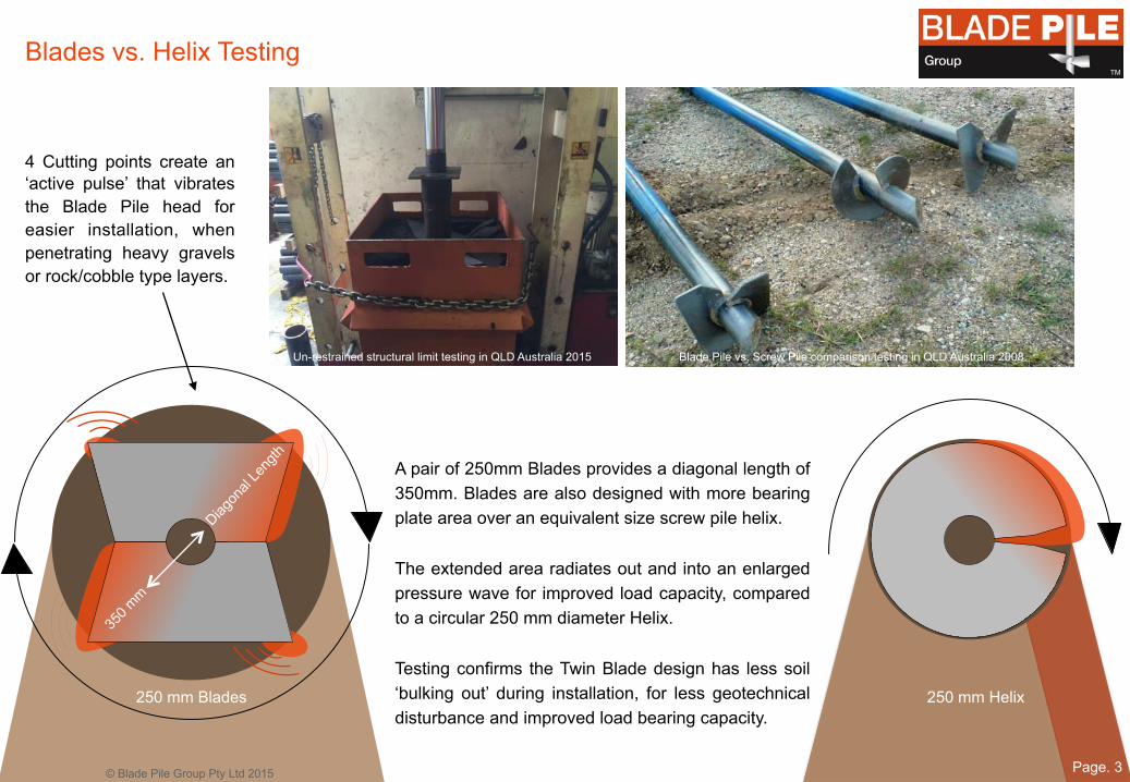
A pair of 250mm Blades provides a diagonal length of 350mm. Blades are also designed with more bearing plate area over an equivalent size screw pile helix. The extended area radiates out and into an enlarged pressure wave for improved load capacity, compared to a circular 250 mm diameter Helix. Testing confirms the Twin Blade design has less soil ‘bulking out’ during installation, for less geotechnical disturbance and improved load bearing capacity.
Blade Pile vs. Screw Pile comparison testing in QLD Australia 2008.
4 Cutting points create an ‘active pulse’ that vibrates the Blade Pile head for easier installation, when penetrating heavy gravels or rock/cobble type layers.
Page. 3
TM
Un-restrained structural limit testing in QLD Australia 2015

Screw piles have one leading edge. A curved pitched helix that augers the soil during install. The single edge induces out of round forces. The trailing edge follows into disturbed material. Through soil settlement, over time bearing capacity will slowly ‘grow’ back into place around the helix area (shaded Orange in diagram). Twin Blade Piles counter balance each other for improved verticality. The Blades ‘sliver’ into the soil with less disturbance for improved ‘end bearing’ compression & tension load capacity. Blade Piles are manufactured from 350 Grade high tensile steel (Average 450 Mpa yield) for a higher torsional install capacity and structural strength. Blade Piles provide a level of installed verticality & positioning for finite tolerance structures, that is simply unattainable with screw piles.
1. 2. 1.
© Blade Pile Group Pty Ltd 2015
Moree Solar Farm - Solar Blade Piles – Verticality & positioning unattainable with screw piles
Page. 4
TM
Blade Pile Screw Pile
Blades vs. Helix
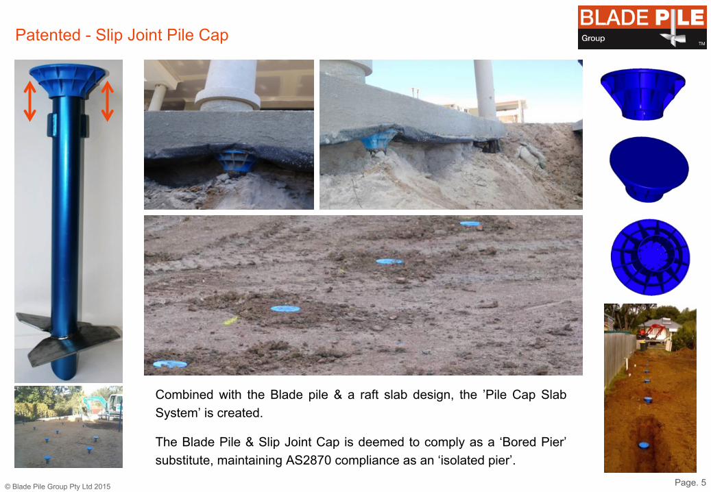
Combined with the Blade pile & a raft slab design, the ’Pile Cap Slab System’ is created.
The Blade Pile & Slip Joint Cap is deemed to comply as a ‘Bored Pier’ substitute, maintaining AS2870 compliance as an ‘isolated pier’.
Patented - Slip Joint Pile Cap
© Blade Pile Group Pty Ltd 2015 Page. 5
TM
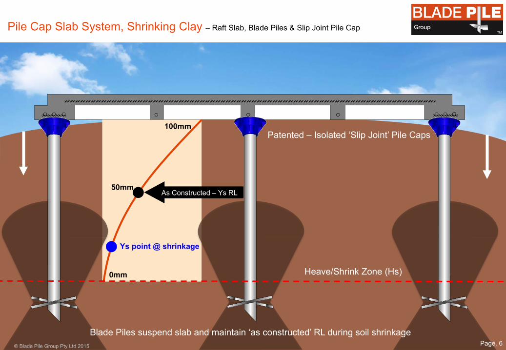
100mm 50mm 0mm
Ys point @ shrinkage
Patented – Isolated ‘Slip Joint’ Pile Caps
Pile Cap Slab System, Shrinking Clay – Raft Slab, Blade Piles & Slip Joint Pile Cap
Heave/Shrink Zone (Hs)
© Blade Pile Group Pty Ltd 2015
As Constructed – Ys RL
Page. 6
TM
Blade Piles suspend slab and maintain ‘as constructed’ RL during soil shrinkage

100mm 50mm 0mm
Pile Cap Slab System, Heaving Clay – Raft Slab, Blade Piles & Slip Joint Pile Cap
Heave/Shrink Zone (Hs)
© Blade Pile Group Pty Ltd 2015
As Constructed – Ys RL
Page. 7
TM
Ys point @ heave
Blade Piles maintain ‘as constructed’ RL during periods of clay heave

100mm 50mm 0mm
Ys point @ shrinkage
Bored Piers are engaged in friction within the reactive Clay zone, forcing the pier to follow the same path & level of heave & shrink movement.
To better manage movement within the Hs zone, the design engineer should consider founding depths relative to allowable slab deflection.
‘0.75 Hs’ Bored Piers in Shrinking Clay Soil – ‘In Friction’ Sucked Down & Rotated Outward by Clay
Heave/Shrink Zone (Hs)
Pier support loss to slab during shrinkage, leads to ‘Hogging’
As Constructed – Ys RL
© Blade Pile Group Pty Ltd 2015 Page. 8
TM
0.75 Hs 0.75 Hs
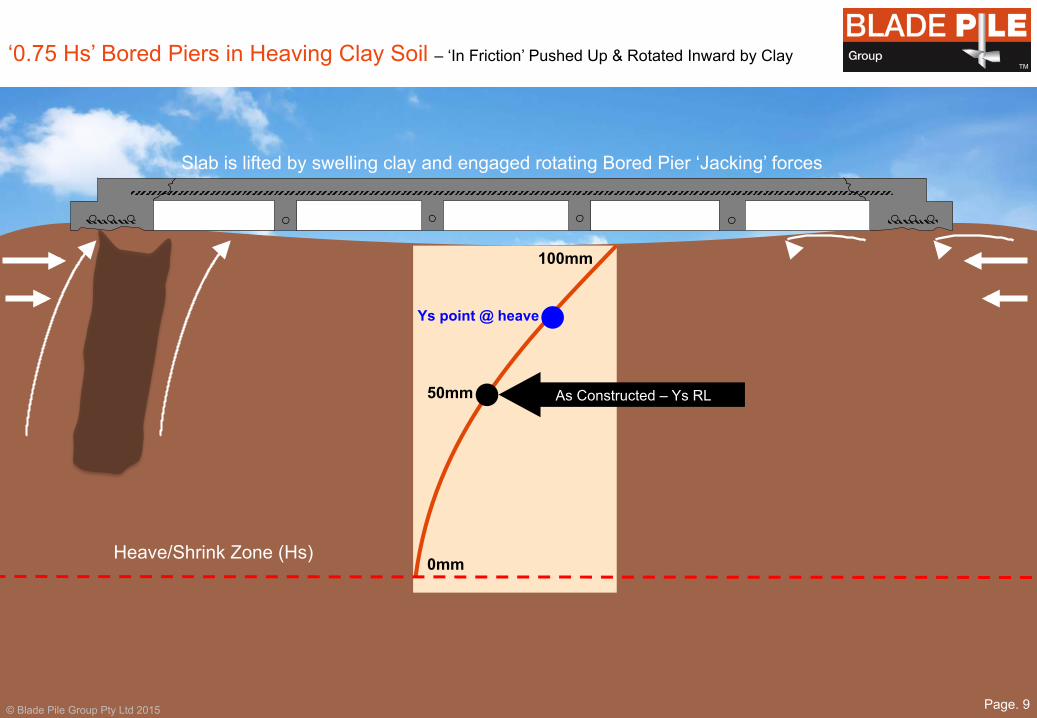
‘0.75 Hs’ Bored Piers in Heaving Clay Soil – ‘In Friction’ Pushed Up & Rotated Inward by Clay
Heave/Shrink Zone (Hs)
Slab is lifted by swelling clay and engaged rotating Bored Pier ‘Jacking’ forces
100mm 50mm 0mm
Ys point @ heave
As Constructed – Ys RL
© Blade Pile Group Pty Ltd 2015 Page. 9
TM
0.75 Hs 0.75 Hs
Bored Piers are engaged in friction within the reactive Clay zone, forcing the pier to follow the same path & level of heave & shrink movement.
To better manage movement within the Hs zone, the design engineer should consider founding depths relative to allowable slab deflection.

Bored Pier Failure in Shrinking Clay Soil – Single Level Dwelling, Booval, Ipswich QLD, 2014
© Blade Pile Group Pty Ltd 2015
Pier support loss to slab during shrinkage leads to ‘Hogging’, confirmed by internal inspection of dwelling
50 Cent Coin placed between bored pier & underside of slab perimeter beam. Hand excavation & flushing with water used to expose top of Bored Pier.
Significant separation between bored pier & raft slab from soil shrinkage. Soil shrinkage & pier separation was visible around entire property. Top of the Bored Pier visibly ‘leaning out’ from the underside of raft slab.
Page. 10
TM

Blade Pile & Pile Cap – A solution for all types of problem sites
© Blade Pile Group Pty Ltd 2015
Heave/Shrink Zone (Hs)
Sewers
Neighbouring Footings
Tree Root Affects
Page. 11
Fill or Poor Quality Soils
TM

Bored Pier vs. Blade Pile & Pile Cap – How Blade Piles offer a superior alternative
© Blade Pile Group Pty Ltd 2015 Page. 12
TM
Bored Pier – Reduction Factor to AS2870 (2011) - Cl 1.4.2 Blade Pile – Reduction Factor to AS2159 (2009) - Ø g %
Blad
e Tech
nical M
anual S
ept 2
01
3.d
ocx
Pag
e 40
of 4
5 DRA
FT O
NLY
Stru
cterre
Refe
rence
J10
44
93
Date
d 4
August 2
01
0
!
!
!
!!
!!!!!
!
© Blade Pile Group Pty Ltd 2015
TM
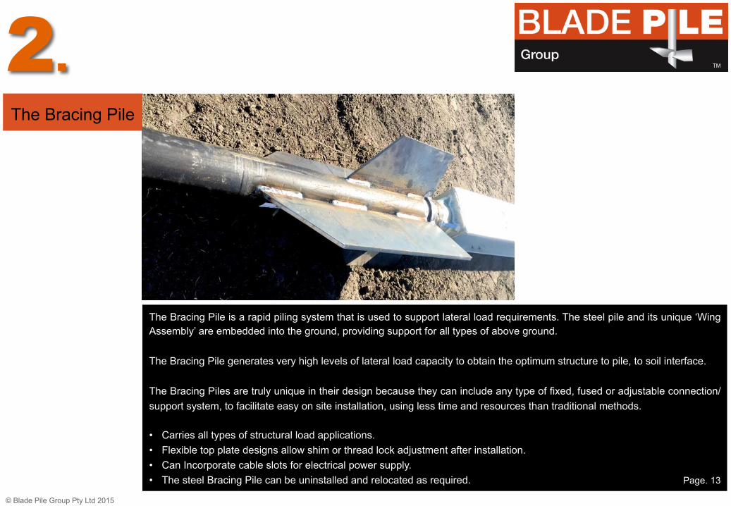
The Bracing Pile is a rapid piling system that is used to support lateral load requirements. The steel pile and its unique ‘Wing Assembly’ are embedded into the ground, providing support for all types of above ground. The Bracing Pile generates very high levels of lateral load capacity to obtain the optimum structure to pile, to soil interface. The Bracing Piles are truly unique in their design because they can include any type of fixed, fused or adjustable connection/support system, to facilitate easy on site installation, using less time and resources than traditional methods. • Carries all types of structural load applications. • Flexible top plate designs allow shim or thread lock adjustment after installation. • Can Incorporate cable slots for electrical power supply. • The steel Bracing Pile can be uninstalled and relocated as required. Page. 13
The Bracing Pile
2.
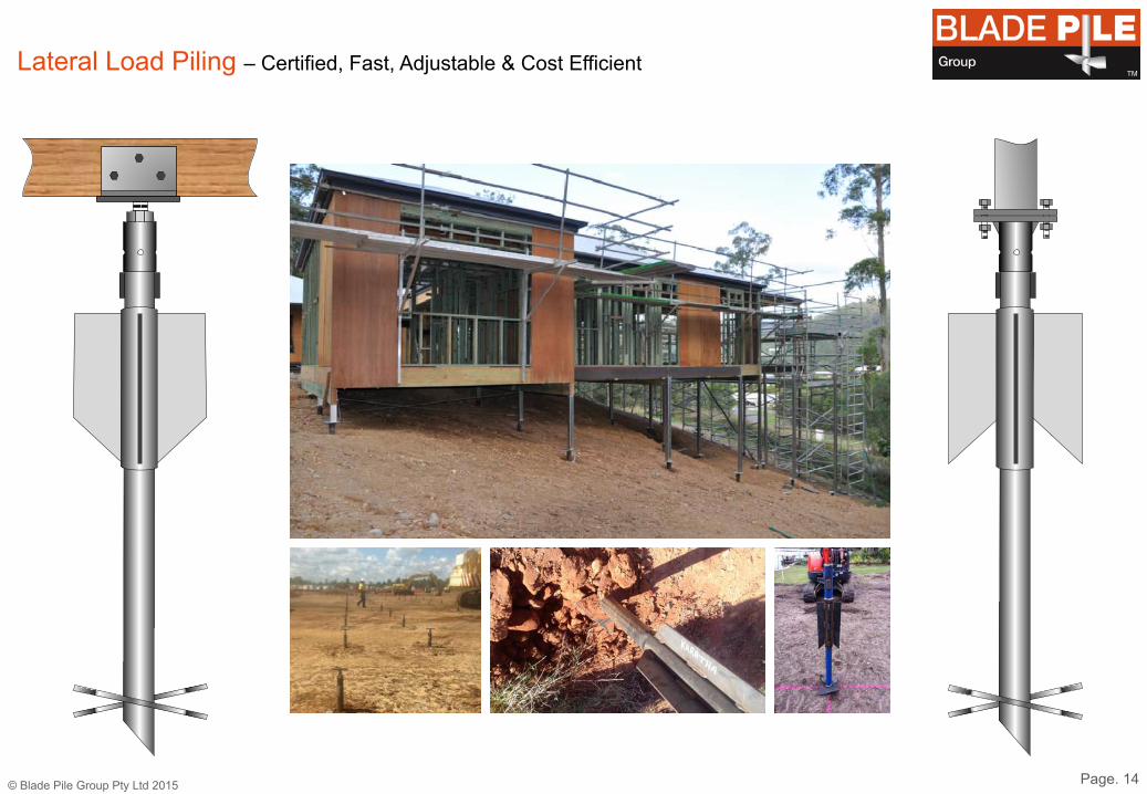
Lateral Load Piling – Certified, Fast, Adjustable & Cost Efficient
© Blade Pile Group Pty Ltd 2015 Page. 14
TM

World Leading Technology – A Geodynamic Design for Every Need
Page. 15
TM
© Blade Pile Group Pty Ltd 2015
Solar Blade Piles supporting the Moree Solar Farm
Solar Blade Piles installation, the Moree Solar Farm
Bracing Blade Piles for the Caribbean Pirates Movie
Bracing Blade Piles supporting Pirate Ship on slipway

Pile Connection Innovation – A Solution Designed & Fabricated for All Needs
© Blade Pile Group Pty Ltd 2015
16
Page. 16
TM

TM
© Blade Pile Group Pty Ltd 2015
Pile Performance
Page. 17
TM 3.
Blade Piles being installed into the Brisbane River, for the Kingsford Smith Drive freeway widening, for the City to Airport Link

18
TM
Moree Solar Farm (MSF) – NSW
• Australia’s largest ever ‘screw in’ steel piling contract – 32,000 Solar Blade Piles • 6,400 tons of steel Solar Blade Piles, supplied & installed on time & on budget • Made possible by the patented Solar Blade Pile, created by the Blade Pile Group

© Blade Pile Group Pty Ltd 2015 Page. 19
Blade Pile Analysis – Ensures ULS is met, with optimum design for site conditions TM
Pile Capacity (Shaft)
Factored 50 Year life for Corrosion - ULS
Structural Load
(dead g + live q) Factored for required - ULS
Ultimate Geotechnical Capacity
(φg Rd,ug) Determines Blade Pile sizes - ULS
Site Condition Filter – Blade Sizes & Types
Blades ‘tuned’ to site specific conditions

Australian*Standards*Compliant*1*Blade*Pile*Performance*Design*Chart*1*Matching*Structural*Load*to*Pile*Capacity*&*Geotechnical*Capacity !!VERY!STIFF!CLAY 200!kPa!(Cu)!!
AS1170!7!STRUCTURAL!LOAD AS1163!&!AS4100!7!PILE!CAPACITY AS2159!7!ULTIMATE!GEOTECHNICAL!CAPACITY Øg!%!Factored
Un7Factored!Loads!kN Total!kN Total!kN 200!kPa!(Cu)BLADE!PILE !Blade!Pile!7!Ult!Geo!Strength!@!Embedment!Depth!7!Metres!&!kN Ult!Geo!Strength Total!kN
Dead!Load!g Live!Load!q Total!kN 1.2 1.5 ULS ØNc!(Ult!Axial) Non Mild Moderate ULS Optimum!Blade!SetsProduct!Code 1.50 2.00 2.50 3.00 3.50 4.00 4.50 5.00 Required ULS11.1 11.1 22.2 13.3 16.7 30 1 280 248 211 138 138 1200*x*100*x*8BP.Y.1 76 87 97 108 120 131 142 154 50 30
16.7 16.7 33.3 20.0 25.0 45 2 280 248 211 138 138 2200*x*100*x*8BP.Y.1 76 87 97 108 120 131 142 154 75 45
22.2 22.2 44.4 26.7 33.3 60 3 280 248 211 138 138 3250*x*125*x*8BP.Y.3 99 113 124 135 147 158 170 202 100 60
27.8 27.8 55.6 33.3 41.7 75 4 280 248 211 138 138 4250*x*125*x*8BP.Y.3 99 113 125 135 147 158 170 202 125 75
33.3 33.3 66.7 40.0 50.0 90 5 280 248 211 138 138 5300*x*150*x*8BP.Y.8 125 142 165 178 192 206 220 235 150 90
38.9 38.9 77.8 46.7 58.3 105 6 280 248 211 138 138 6300*x*150*x*8BP.Y.8 125 142 165 178 192 206 220 235 175 105
44.4 44.4 88.9 53.3 66.7 120 7 280 248 211 138 138 7350*x*175*x*10BP.Y.16 160 180 199 215 229 260 276 293 200 120
50.0 50.0 100.0 60.0 75.0 135 8 340 306 272 204 204 8400*x*200*x*10BP.Y.24 199 223 245 268 286 302 319 336 225 135
55.6 55.6 111.1 66.7 83.3 150 9 340 306 272 204 204 9400*x*200*x*10BP.Y.24 199 223 245 268 286 302 319 336 250 150
61.1 61.1 122.2 73.3 91.7 165 10 340 306 272 204 204 10300*x*150*x*8*DUALBP.S.8 242 275 320 345 372 399 426 455 275 165
66.7 66.7 133.3 80.0 100.0 180 11 340 306 272 204 204 11300*x*150*x*8*DUALBP.S.8 242 275 320 345 372 399 426 455 300 180
72.2 72.2 144.4 86.7 108.3 195 12 340 306 272 204 204 12300*x*150*x*8*DUALBP.S.8 242 275 320 345 372 399 426 455 325 195
77.8 77.8 155.6 93.3 116.7 210 13 453 410 367 282 282 13350*x*175*x*10*DUALBP.S.17 307 345 382 412 439 499 529 562 350 210
83.3 83.3 166.7 100.0 125.0 225 14 453 410 367 282 282 14350*x*175*x*10*DUALBP.S.17 307 345 382 412 439 499 529 562 375 225
88.9 88.9 177.8 106.7 133.3 240 15 453 410 367 282 282 15350*x*175*x*10*DUALBP.S.17 307 345 382 412 439 499 529 562 400 240
94.4 94.4 188.9 113.3 141.7 255 16 453 410 367 282 282 16400*x*200*x*10*DUALBP.S.25 408 459 508 548 584 663 703 747 425 255
100.0 100.0 200.0 120.0 150.0 270 17 453 410 367 282 282 17400*x*200*x*10*DUALBP.S.25 408 459 508 548 584 663 703 747 450 270
105.6 105.6 211.1 126.7 158.3 285 18 633 577 509 371 371 18400*x*200*x*10*DUALBP.S.28 382 428 470 515 549 580 613 645 475 285
111.1 111.1 222.2 133.3 166.7 300 19 633 577 509 371 371 19400*x*200*x*10*DUALBP.S.28 382 428 470 515 549 580 613 645 500 300
116.7 116.7 233.3 140.0 175.0 315 20 633 577 509 371 371 20350*x*175*x*10*TRIPLEBP.M.19 447 503 556 600 640 726 771 818 525 315
122.2 122.2 244.4 146.7 183.3 330 21 633 577 509 371 371 21350*x*175*x*10*TRIPLEBP.M.19 447 503 556 600 640 726 771 818 550 330
127.8 127.8 255.6 153.3 191.7 345 22 633 577 509 371 371 22350*x*175*x*10*TRIPLEBP.M.19 447 503 556 600 640 726 771 818 575 345
133.3 133.3 266.7 160.0 200.0 360 23 633 577 509 371 371 23350*x*175*x*10*TRIPLEBP.M.19 447 503 556 600 640 726 771 818 600 360
©*Copyright*JCZT*Pty*Ltd*2016
ULS!=!1.2g!+!1.5q!=!1.35!SLS Exposure!categories!7!50!Year!capacity
© Blade Pile Group Pty Ltd 2015 Page. 20
TM

Pile Testing For Deflections – Optimising end bearing ‘pressure bulb’
© Blade Pile Group Pty Ltd 2015
Within Allowable Slab Deflection?
Page. 21
TM
Øg .65 = 0 ULS
Within Allowable Pile Deflection Limit/Failure Deflection? Installed RL Position 0 mm 0 kN Ult 11.8 mm Deflection
138 kN Ult Geotechnical 25.0 mm Deflection 210 kN Ult Geotechnical
50.0 mm Deflection? 280 kN Ult Geotechnical?
Øg 0.65 = 90 kN ULS
Øg 0 .65 = 136 kN ULS 50 Year = 120 kN ULS Limit / Failure?
Øg 0.65 = 182 kN ULS 50 Year = 120 kN ULS
Note: End bearing ‘pressure bulb’ restrained by overburden pressure of surrounding soil (VSC)…… to a limit point
Øg allowed solely from ‘on site’ AS2159 static load pile testing - 1.0% = 0.55, 2.0% = 0.65, 3.0% = 0.71, 4.0% = 0.76 (% of total piles).
© Blade Pile Group Pty Ltd 2015 Page. 22
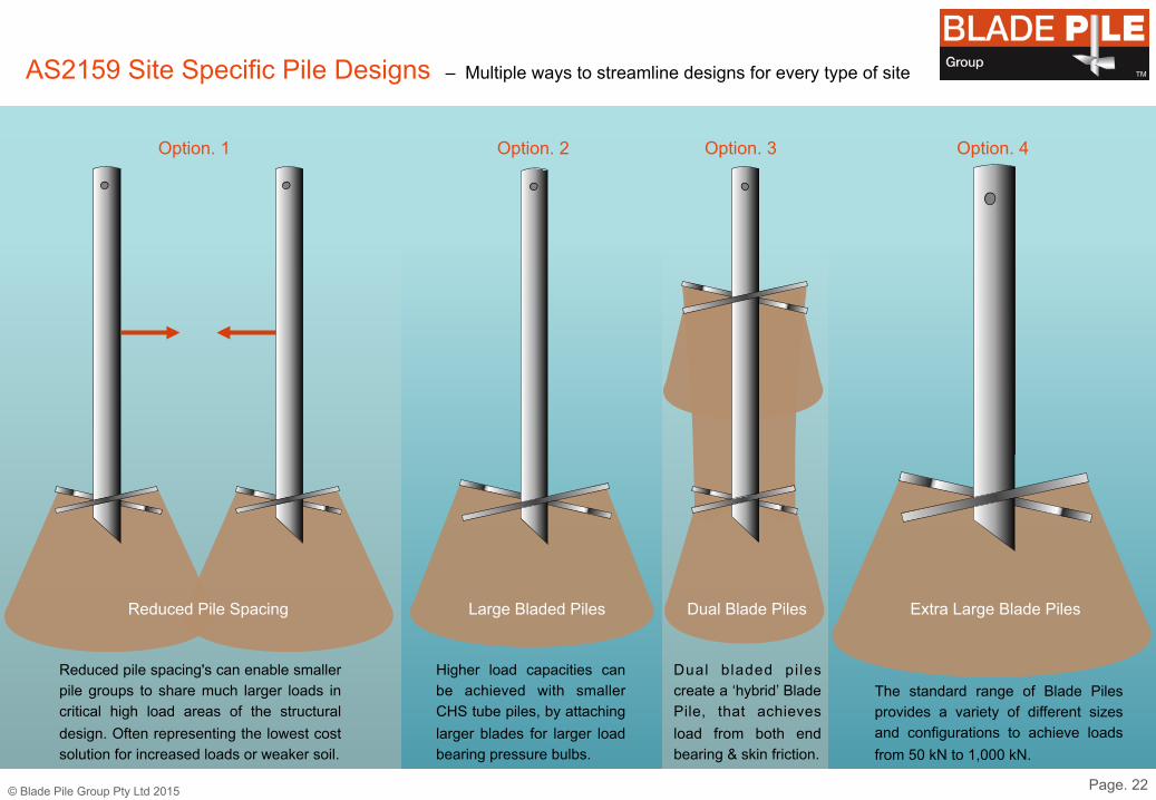
AS2159 Site Specific Pile Designs – Multiple ways to streamline designs for every type of site TM
Dual Blade Piles Large Bladed Piles Reduced Pile Spacing Extra Large Blade Piles
Reduced pile spacing's can enable smaller pile groups to share much larger loads in critical high load areas of the structural design. Often representing the lowest cost solution for increased loads or weaker soil.
Higher load capacities can be achieved with smaller CHS tube piles, by attaching larger blades for larger load bearing pressure bulbs.
Dual bladed pi les create a ‘hybrid’ Blade Pile, that achieves load from both end bearing & skin friction.
The standard range of Blade Piles provides a variety of different sizes and configurations to achieve loads from 50 kN to 1,000 kN.
Option. 1 Option. 2 Option. 3 Option. 4

TM
© Blade Pile Group Pty Ltd 2015
Design Data
• Current subsidence policies for residential site investigations (AS2870) are insufficient for AS2159. Bore logs need to identify natural material with adequate soil strength data.
• Accurate SLS or ULS loads for each pile location is essential, for design calculations.
• Generic engineering load specifications simply forces Blade Pile to over-design with larger, deeper and more expensive piles.
Page. 23
4.

Page. 24
TM
Geotech Reporting Issue – Low Cost AS2870 Geotech reporting is high risk & high cost TM
Dense Sand
M/Dense Sand
????????
To 4.5 Metres To 4.5 Metres
To 3.0 Metres
Page. 25
TM
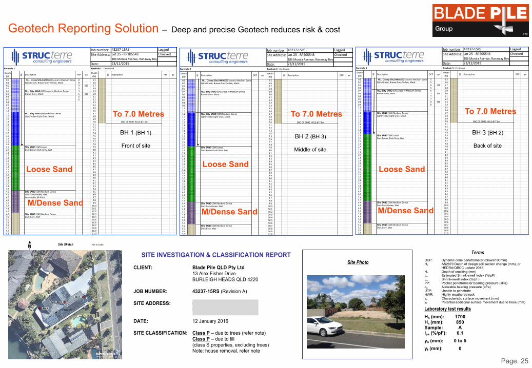
Geotech Reporting Solution – Deep and precise Geotech reduces risk & cost TM
P
age 2 of 8
ResidentialCom
mercial &
InfrastructureGeotechnical
EnergyAssessm
entInspect &Investigate
Environmental
Job$number: 43237/15RS Logged F.OSite$Address: Lot$25$/$RP205543 Checked LM
186$Morala$Avenue,$Runaway$BayDate: 23/12/2015
Depth$(M) fil
l Description PSP qaDepth$(M) fil
l Description PSP qa
0.0 8 5.50.1 With$Gravel,$Brown/Grey/Yellow,$Moist 8 5.60.2 4 110 5.70.3 5 5.80.4 FILL:%Silty%SAND%(SP)$Loose$to$Medium$Dense 5 5.90.5 Brown/Grey,$Moist 6 130 6.00.6 5 6.10.7 6 6.20.8 6.30.9 6.41.0 6.51.1 6.61.2 FILL:%Silty%SAND%(SM)$Medium$Dense 6.71.3 Light$Yellow/Light$Grey,$Moist 6.81.4 6.91.5 7.0 END$OF$BORE$HOLE$@$7.0m1.6 7.11.7 7.21.8 7.31.9 7.42.0 7.52.1 7.62.2 7.72.3 7.82.4 Silty%SAND%(SM)$Loose 7.92.5 Dark$Brown/Dark$Grey,$Wet 8.02.6 8.12.7 8.22.8 8.32.9 8.43.0 8.53.1 8.63.2 8.73.3 8.83.4 8.93.5 9.03.6 9.13.7 9.23.8 9.33.9 9.44.0 Silty%SAND%(SM)$Medium$Dense 9.54.1 Dark$Grey/Brown,$Wet 9.64.2 (watertable$@$4.0m) 9.74.3 9.84.4 9.94.5 10.04.6 10.14.7 10.24.8 Silty%SAND%(SM)$Medium$Dense 10.34.9 Dark$Grey,$Wet 10.45.0 10.55.1 10.65.2 10.75.3 10.85.4 10.95.5 11.0
FILL:%Clayey%Silty%SAND%(SC)$Loose$to$Medium$Dense
Borehole$1
Borehole%1%%$ Borehole%1%$/$Continued
P
age 3 of 8
ResidentialCom
mercial &
InfrastructureGeotechnical
EnergyAssessm
entInspect &Investigate
Environmental
Job$number: 43237/15RS Logged F.OSite$Address: Lot$25$/$RP205543 Checked LM
186$Morala$Avenue,$Runaway$BayDate: 23/12/2015
Depth$(M) fil
l Description DCP qaDepth$(M) fil
l Description DCP qa
0.0 5.50.1 With$Gravel,$Brown/Grey/Yellow,$Moist 5.60.2 5.70.3 5.80.4 FILL:%Silty%SAND%(SP)$Loose$to$Medium$Dense 5.90.5 Brown/Grey,$Moist 6.00.6 6.10.7 6.20.8 6.30.9 6.41.0 6.51.1 6.61.2 FILL:%Silty%SAND%(SM)$Medium$Dense 6.71.3 Light$Yellow/Light$Grey,$Moist 6.81.4 6.91.5 7.0 END$OF$BORE$HOLE$@$7.0m1.6 7.11.7 7.21.8 7.31.9 7.42.0 7.52.1 7.62.2 7.72.3 7.82.4 Silty%SAND%(SM)$Loose 7.92.5 Dark$Brown/Dark$Grey,$Wet 8.02.6 8.12.7 8.22.8 8.32.9 8.43.0 8.53.1 8.63.2 8.73.3 8.83.4 8.93.5 9.03.6 9.13.7 9.23.8 9.33.9 9.44.0 9.54.1 9.64.2 9.74.3 9.84.4 Silty%SAND%(SM)$Medium$Dense 9.94.5 Dark$Grey/Brown,$Wet 10.04.6 10.14.7 10.24.8 10.34.9 10.45.0 10.55.1 10.65.2 Silty%SAND%(SM)$Medium$Dense 10.75.3 Dark$Grey,$Wet 10.85.4 10.95.5 11.0
FILL:%Clayey%Silty%SAND%(SC)$Loose$to$Medium$Dense
Borehole$2
Borehole%2%%$ Borehole%2$/$Continued
P
age 4 of 8
ResidentialCom
mercial &
InfrastructureGeotechnical
EnergyAssessm
entInspect &Investigate
Environmental
Job$number: 43237/15RS Logged F.OSite$Address: Lot$25$/$RP205543 Checked LM
186$Morala$Avenue,$Runaway$BayDate: 23/12/2015
Depth$(M) fil
l Description DCP qaDepth$(M) fil
l Description DCP qa
0.0 5 5.50.1 With$Gravel,$Brown/Grey/Yellow,$Moist 5 5.60.2 6 130 5.70.3 5 5.80.4 FILL:%Silty%SAND%(SP)$Loose$to$Medium$Dense 6 5.90.5 Brown/Grey,$Moist 7 160 6.00.6 7 6.10.7 7 6.20.8 8 180 6.30.9 8 6.41.0 6.51.1 6.61.2 Silty%SAND%(SM)$Medium$Dense 6.71.3 Light$Yellow/Light$Grey,$Moist 6.81.4 6.91.5 7.0 END$OF$BORE$HOLE$@$7.0m1.6 7.11.7 7.21.8 7.31.9 7.42.0 Silty%SAND%(SM)$Loose 7.52.1 Dark$Brown/Dark$Grey,$Wet 7.62.2 7.72.3 7.82.4 7.92.5 8.02.6 8.12.7 8.22.8 8.32.9 8.43.0 8.53.1 8.63.2 8.73.3 8.83.4 8.93.5 9.03.6 9.13.7 9.23.8 9.33.9 9.44.0 9.54.1 9.64.2 9.74.3 9.84.4 Silty%SAND%(SM)$Medium$Dense 9.94.5 Dark$Grey/Brown,$Wet 10.04.6 10.14.7 10.24.8 10.34.9 10.45.0 10.55.1 10.65.2 Silty%SAND%(SM)$Medium$Dense 10.75.3 Dark$Grey,$Wet 10.85.4 10.95.5 11.0
FILL:%Clayey%Silty%SAND%(SC)$Loose$to$Medium$Dense
Borehole$3
Borehole%3%%$ Borehole%3$/$Continued
Page 5 of 8
Residential Commercial &InfrastructureGeotechnical
EnergyAssessment
Inspect &Investigate Environmental
Site Photo
Terms DCP: Dynamic cone penetrometer (blows/100mm) Hs: AS2870 Depth of design soil suction change (mm), or HEDRA/QBCC update 2015. Hc: Depth of cracking (mm) Ips: Estimated Shrink-swell index (%/pF) Iss: Shrink-swell index (%/pF) PP: Pocket penetrometer bearing pressure (kPa) qa: Allowable bearing pressure (kPa) UTP: Unable to penetrate HWR: Highly weathered rock ys: Characteristic surface movement (mm) yt: Potential additional surface movement due to trees (mm)
Laboratory test results
1700 850 A
0.1
0 to 5
0
Hs (mm): Hc (mm): Sample: Ips (%/pF):
ys (mm):
yt (mm):
Not to scale Site Sketch
BH 1
BH 3 slope 1%
H=15m D=8m
BH 2
Page 1 of 8
Residential Commercial &InfrastructureGeotechnical
EnergyAssessment
Inspect &Investigate Environmental
SITE INVESTIGATION & CLASSIFICATION REPORT
This report is based on our field and laboratory test results and site and construction information (if any) supplied by the client. Should proposed construction vary from those advised, this office should be notified as additional testing may be required. It should be also noted that the test results may not be relevant if the location of a proposed structure varies from that originally advised. This report relates to the ground conditions on the property at the time of the site investigation. If so advised by the client, this report has considered the proposed site preparation. If unadvised cutting or filling is proposed or carried out, additional testing may be required to reclassify the site as indicated in Clause 2.3.2 (B) and Clause 2.5.3 of AS2870-2011. This site has been classified in accordance with Section 2 of AS2870-2011. The characteristic surface movement, ys, has been determined either by shrink and swell tests as specified in AS1289.7.1.1-1992 in accordance with Clause 2.3.2 (i) of AS2870-2011, or by visual-tactile identification of the soil with the assistance of Atterberg Limits in accordance with Clause 2.3.2 (iii) of AS2870-2011. Results of our site investigation are indicated in the attached Soil Test Results page.
Construction Details Site Details Site Preparation Proposed Vegetation: Trees
Residential Slope: Slight Minimal Dwelling Drainage: Poor
CLIENT: Blade Pile QLD Pty Ltd 13 Alex Fisher Drive BURLEIGH HEADS QLD 4220 JOB NUMBER: 43237-15RS (Revision A) SITE ADDRESS: Lot 25, #186 Morala Avenue RUNAWAY BAY 4216 DATE: 12 January 2016 SITE CLASSIFICATION: Class P – due to trees (refer note)
Class P – due to fill (class S properties, excluding trees) Note: house removal, refer note
Loose Sand Loose Sand Loose Sand
BH 1 (BH 1)
Front of site
BH 2 (BH 3)
Middle of site
BH 3 (BH 2)
Back of site
M/Dense Sand M/Dense Sand M/Dense Sand
To 7.0 Metres To 7.0 Metres To 7.0 Metres

Page. 26
TM
Pile Loads Issue – More effort is needed to get it right for the client TM
Providing the wrong pile loads for each location, means the client pays more for piles they don’t need
= 100 kN Un-factored
= 75 kN Un-Factored

43249-15RS SKETCH SK1 PILE LOCATION
BP1
BP1
BP1
BP1
BP1
BP1
BP1 BP1
BP1
BP1
BP1
BP1
BP1 BP1
BP1
BP1
BP1
BP1
BP1
BP1
BP1
BP3
BP3
BP3
BP3
BP3
BP3
BP3
BP3
BP3
BP3
BP3
BP3
BP3
= 90 kN ULS PILE
BP3 BP1
= 50 kN ULS PILE
BP2 = 75 kN ULS PILE
BP3 BP2
BP2 BP2
BP2
BP2
BP2 BP2
BP2
BP2
BP2
BP2 BP2
BP2 BP2
BP2 BP2
BP2
BP2
BP2 BP2
BP2
BP2 BP2
BP2 BP2
BP2 BP2 BP2
BP1
BP1 BP1
BP1
BP2
1-2-063586374059-0000000-07525-000052243031302
Job No: Date:The competent person responsible for the certification of this document:
Name: RPEQ: Signature: Sheet: of
67 Links Avenue North, Eagle Farm Email: PH: (07) 3307 8300 Fax: (07) 3307 8301 ABN: 99 115 038 429 ACN: 115 038 429
4324922/12/2015
Adam Buckley 144811 1
Page. 27
TM
Specified Pile Loads Solution – Calculated pile loads = Lower piling costs TM
Calculating the correct pile load for each location, means the right piles at the right cost for the client
= 37 kN Un-factored
= 55 kN Un-factored
= 67 kN Un-factored

© Blade Pile Group Pty Ltd 2015 Page. 28
Blade Pile Technical Design Manual – To Ensure Compliance to All Relevant Australian Standards TM
Blade Pile Group - PH +61 75593 8788 - 13 Alex Fisher Drive
Burleigh Heads QLD 4220 - PO Box 4478 RTC QLD 4230 Australia
www.bladepile.com - [email protected]
This Technical Design Manual (TDM) has been created for use in the determination, application and design of Blade Piles, Slip Joint Pile Caps,
Piled Slab Systems, Lateral Bracing Piles and connections for Residential, Commercial, Industrial and Civil Construction projects.
Design information, methodologies, calculations and recommendations
documented within this TDM are in accordance with the relevant Australian Standards, to ensure that proper compliance & certification
can be achieved for the mandatory requirements of those standards.
67 Links Ave North, Eagle Farm, Queensland 4009 PO Box 621, Hamilton, QLD 4007Phone (+617) 3307 8300 | Fax (+617) 3307 8301 | Email [email protected] | Web www.structerre.com.au
Perth | Brisbane | Sydney | Bunbury | Geraldton | Gold Coast | Albany | Karratha
ABN 99 115 038 429 Structerre WBA Pty Ltd ACN 115 038 429 trading as Structerre Consulting Engineers (QLD)
Residential Commercial &InfrastructureGeotechnical
EnergyAssessment
Inspect &Investigate Environmental
TM
Residential Commercial &InfrastructureGeotechnical
EnergyAssessment
Inspect &Investigate Environmental
Blade Pile Geotechnical Designs - Piling & Foundation Systems
Technical Design Manual
TM
Blade Pile Systems - 2016 Technical Design Manual
BPG.SCE.TDM.VS.04 - © Copyright JCZT Pty Ltd 2016
www.bladepile.com - [email protected]

© Blade Pile Group Pty Ltd 2015
TM
The Blade Pile Group and its associate company Airformer, have invented & patented the following.
Blade Pile Group - Pile Cap Slab System (For both Waffle or conventional slabs)
And Coming Soon!
Airformer Group- Air Slab System – Air Pod, Mesh Chairs & Pod Lock Bar Chairs
Airformer Group- Blade Slab System – Blade Pod & Blade Plates.
Page. 29
Slab Systems
5.
AIR ����!��� ��� �� ����� � �� !
AIR ����!��� ��� �� ����� � �� !
AIR ����!��� ��� �� ����� � �� !
AIR ����!��� ��� �� ����� � �� !
Bla
de T
echnic
al M
anual S
ept 2
01
3.d
ocx
Page 3
7 o
f 45 D
RA
FT O
NLY
Stru
cte
rre R
efe
rence J
10
44
93
Date
d 4
August 2
01
0
! "#$%&'(#)*+,-#$(
!"#
$%&'()*+%(),-'(.)/&00%(
)1&02)
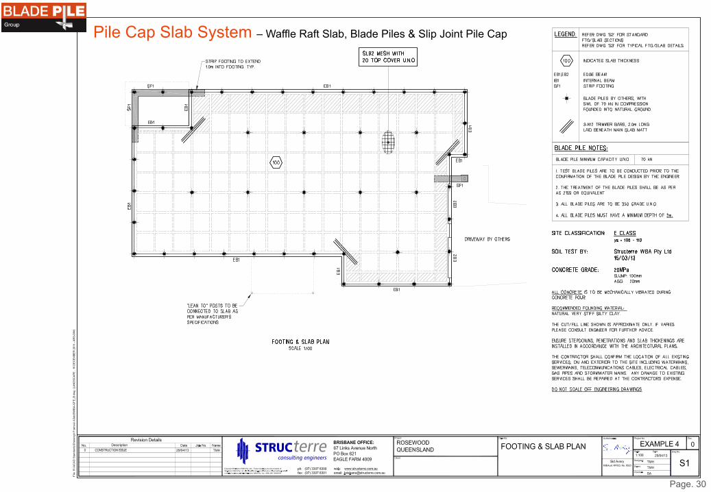
Pile Cap Slab System – Waffle Raft Slab, Blade Piles & Slip Joint Pile Cap
Page. 30

Blad
e T
ech
nical M
anual S
ept 2
01
3.d
ocx
Pag
e 3
8 o
f 45 D
RA
FT O
NLY
Stru
cte
rre R
efe
rence J1
04
49
3 D
ate
d 4
August 2
01
0
Pile Cap Slab System – Waffle Raft Slab, Blade Piles & Slip Joint Pile Cap
Page. 31
Bla
de T
echnic
al M
anual S
ept 2
01
3.d
ocx
Page 3
9 o
f 45 D
RA
FT O
NLY
Stru
cte
rre R
efe
rence J1
04
49
3 D
ate
d 4
August 2
01
0
!"#
$%&'()*+%(),-'(.)/0-1(-2+0-&%)32+44(
-(')5&42)
)
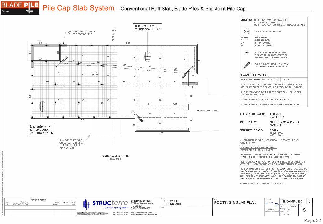
Pile Cap Slab System – Conventional Raft Slab, Blade Piles & Slip Joint Pile Cap
Page. 32

Blad
e Tech
nical M
anual S
ept 2
01
3.d
ocx
Pag
e 40
of 4
5 DRA
FT O
NLY
Stru
cterre
Refe
rence
J10
44
93
Date
d 4
August 2
01
0
!
!
!
!!
!!!!!
!Pile Cap Slab System – Conventional Raft Slab, Blade Piles & Slip Joint Pile Cap
Page. 33

Page. 34

© Blade Pile Group Pty Ltd 2015
TM
Blade Pile Group and its associated companies understand the importance of ongoing independent structural & geotechnical testing of foundation products and are now able to assist other parties in acquiring expert pile testing services. Independent verification and certification of Blade Pile Group products continues to be carried out by some of Australia’s leading engineers, testing laboratories and consulting engineering companies. Some of the parties that have worked with Blade Pile to provide testing include Structerre Consulting Engineers, GHD Consulting Engineers WA, Aurecon SA, Prompt Certification WA, URS SA, University of South Australia, Griffith University QLD, ALS Group, Foundations Specialist Group, Alfa Labs QLD and Dr. Peter Mitchell. The Blade Pile Group and its associated companies have now established pile testing services for other parties. Our group works directly with certifying engineers in Australia and overseas, to ensure independent, accurate & reliable certification services that meet all Standards, Building Codes and regulatory requirements. 35 Page. 35
6. Pile Testing

BLADE&PILE&TEST&GRAPH&.&Tension&Test&.&vs.22.07.15&
Test%Stage: 1 Test%Number: 45 Date: 20.08.15 Pile%Type: AM89&External&Array&Pile&@&2500&mm
Site%Address: MSF&Solar&Farm&project,&Moree&NSW
Client/Project%Details: GLC Test%Pile%Position: PS01N3T12P07
Each Test%Load Displacement
No. kN NGL
1 0.00 0.00
2 3.12 0.09
3 4.16 0.13
4 5.20 0.13
5 6.24 0.16
6 7.28 0.16
7 8.32 0.18
8 9.36 0.22
9 10.40 0.30
10 8.32 0.26
11 6.24 0.21
12 4.16 0.14
13 2.08 0.07
14 0.00 0.00
15
Tension%Test
0.00%
0.09%
0.13%
0.13%
0.16%
0.16%
0.18%
0.22%
0.30%
0.26%
0.21%
0.14%
0.07%
0.00%0.00%
2.00%
4.00%
6.00%
8.00%
10.00%
12.00%
0.00% 0.05% 0.10% 0.15% 0.20% 0.25% 0.30% 0.35%
Test%Loa
d%(m
m)%
Geotechnical%Displacement%(mm)%
Geotechnical%Displacement%for%given%Test%Load%
36
Tension ‘Pull Up’

BLADE&PILE&TEST&GRAPH&.&Compression&Test&.&vs.22.07.15&
Test%Stage: 3 Test%Number: 131&OM Date: 24.09.15 Pile%Type: OM&Building&114&Pile&&&Dual&350&Blades
Site%Address: MSF&Solar&Farm&project,&Moree&NSW Install%Torque:
Client/Project%Details: Catcon&.&For&GLC Test%Pile%Position: OM&Building&
Each Test%Load Displacement%
No. kN NGL&(mm)
0 0.00 0.00
1 33.90 1.51
2 45.20 1.87
3 56.50 2.14
4 67.80 2.45
5 79.10 2.78
6 90.40 2.95
7 101.70 3.40
8 113.00 3.74
9 90.40 3.73
10 67.80 3.56
11 45.20 3.29
12 22.60 2.96
13 0.00 2.52
14
15
COMPRESSION%TEST
0.00%
1.51%
1.87%
2.14%
2.45%
2.78%
2.95%
3.40%
3.74%
3.73%
3.56%
3.29%
2.96%
2.52%0.00%
20.00%
40.00%
60.00%
80.00%
100.00%
120.00%
0.00% 0.50% 1.00% 1.50% 2.00% 2.50% 3.00% 3.50% 4.00%
Test%Loa
d%(kN)%
Geotechnical%Displacement%(mm)%
Geotechnical%Displacement%for%given%Test%Load%
37

BLADE&PILE&TEST&GRAPH&.&Lateral&Test&.&vs.22.07.15&
Test%Stage: 3 Test%Number: 38 Date: 17.08.15 Pile%Type: AM89&External&Array&Pile&@&2500&mm
Site%Address: Moree&Solar&Farm&project&.&Moree&NSW
Client/Project%Details: GLC Test%Pile%Position: Pile&PS01N4T13P02&.&GPS&East:&TBA&.&North:&TBA
Each Test%LoadGeotechnical%Displacement Deflection
No. kN Bottom&(mm) Top&(mm)
Start 0.00 0.00
50%SLS 1.57 1.80 7.00
Rebound 0.00 0.28
75%SLS 2.35 3.75 15.00
Rebound 0.00 0.38
100%%SLS 3.14 5.62 21.00
Rebound 0.00 0.46
125%%SLS 3.92 6.52 24.00
Rebound 0.00 0.49
150%%SLS 4.71 7.79 29.00
Rebound 0.00 0.55
Summary%Notes:
LATERAL%TEST
0.00%
1.80%
0.28%
3.75%
0.38%
5.62%
0.46%
6.52%
0.49%
7.79%
0.55%0.00%
0.50%
1.00%
1.50%
2.00%
2.50%
3.00%
3.50%
4.00%
4.50%
5.00%
0.00% 1.00% 2.00% 3.00% 4.00% 5.00% 6.00% 7.00% 8.00% 9.00%
Test%Loa
d%(kN)%
Geotechnical%Displacement%(mm)%
Geotechnical%Displacement%(boRom)%for%given%Test%Load%
0%
1.57%
2.35%
3.14%
3.92%
4.71%
0.00%
1.00%
2.00%
3.00%
4.00%
5.00%
0.00% 5.00% 10.00% 15.00% 20.00% 25.00% 30.00% 35.00%
Test%Loa
d%(kN)%
DeflecUon%at%the%top%of%pile%(mm)%
DeflecUon%at%top%of%pier%for%given%Test%Load%
38
Lateral ‘Side Push’

Blade Pile – Destruction Testing to Determine & Optimise Geodynamic Performance
© Blade Pile Group Pty Ltd 2015
Blade Piles are continually tested beyond their limit, to verify and certify the Blade design, fusion welded connections and there relationship with a given CHS pipe.
All these elements are designed to perform equally to there limit, with ZERO allowable tolerance for weld failure, to ensure the best possible performance in all Geotechnical environments.
Extreme Iron Stone Cobble Test Karratha WA
Torque Plastic Limit Test Moree NSW High Torque & Speed Impact Test Moree NSW
Page. 39
Ground Penetration Test Moree NSW
Weld Limit Testing – Alfa Lab Brisbane QLD High Torque & Speed Impact Test Moree NSW
TM
AlfaTest
“Delivering Results”
Page 1 of 9
AlfaTest Pty Ltd A.B.N. 58 096 333 774 PO Box 229, Salisbury QLD 4107 Unit 3/121 Evans Rd, Salisbury, Qld 4107 Phone: (07) 3715 3400 Fax: (07) 3715 3401 Email: [email protected]
This document may not be reproduced except in full. Form No: R054 Version No: 1
MECHANICAL TESTING REPORT RE-ISSUE AlfaTest Report No: 20150178M01 Re-issue Date of Inspection: 20 January 2015
Location of Test: Brisbane Laboratory, Qld Client Order No: 01338
Client Name/Address: Blade Pile Group Pty Ltd 13 Alex Fisher Drive, Burleigh Heads, Qld 4220
Client Job No: Not specified
Project Details: Static load testing of supplied samples
Item Details: M01 - 89mm diameter pipe, no gussets M02 - 89mm diameter pipe with 2 gussets M04 - 76mm diameter pipe without gussets M05 - 89mm diameter pipe with 4 gussets
Sample Details: Refer Test Results
TECHNICAL DETAILS STATIC LOAD TEST
Test Procedure: TP 230 Test Spec: Client’s Requirements Client Requirements: Test and report results Acceptance Spec: Client’s Requirements Material Spec: Grade 350 (Fabricated Parts) Test Equipment Equipment: Field Box Equipment No: 480 Equipment: 700 bar Transducer Equipment No: 543 Equipment: 5 tonne Ram Equipment No: 570 Equipment: Laser Distant Measurer Equipment No: 1933 Sample Condition Time of Test: 01:00pm & 03:00pm, 20 January 2015 Test Restrictions/ Deviations:
Nil
Compliance: Refer Test Results
Technician/s: Fabian Lyons Approved by: Fabian Lyons George YunHui Jiang
Signature:
Jabin Kirk
Re-issue Date: 27 January 2015

TM
© Blade Pile Group Pty Ltd 2015
Certification
• Many piering/piling companies provide certification for foundation works that may not be compliant if they design outside the relevant Australian Standard or, not verified that completed works comply with the Engineers design & specification.
• A certificate that only states works were completed & compliant to a given standard, without a Pile Design Summary Report with calculations to support their pier/pile design, is incomplete and therefore not acceptable for AS2159 certification.
Page. 40
TM 7.

32,000 Solar Blade Piles – 2015 - Moree Solar Farm – NSW Australia
© Blade Pile Group Pty Ltd 2015 Page. 41
$178,000,000 Moree Solar Farm – NSW Australia
Thank You For Your Time


![Pile Foundation Design[1] - ITDmtp.itd.co.th/ITD-CP/data/PileFoundationDesign.pdf · Introduction to pile foundations Pile foundation design Load on piles Single pile design Pile](https://img.dokumen.tips/doc/110x75/5a6ffb387f8b9ab1538b8376/pile-foundation-design1-itdmtpitdcothitd-cpdatapilefoundationdesignpdfpdf.jpg)