Embed Size (px)
Citation preview
Technical Detailed Guide
Aruba Mobility ControllersValidated Reference Design
Version 8
ARUBA MOBILITY CONTROLLERS VALIDATED REFERENCE DESIGN
Copyright© 2011 Aruba Networks, Inc. AirWave®, Aruba Networks®, Aruba Mobility Management System®, Bluescanner, For Wireless That Works®, Mobile Edge Architecture®, People Move. Networks Must Follow®, RFprotect®, The All Wireless Workplace Is Now Open For Business, Green Island, and The Mobile Edge Company® are trademarks of Aruba Networks, Inc. All rights reserved. Aruba Networks reserves the right to change, modify, transfer, or otherwise revise this publication and the product specifications without notice. While Aruba uses commercially reasonable efforts to ensure the accuracy of the specifications contained in this document, Aruba will assume no responsibility for any errors or omissions.
Open Source CodeCertain Aruba products include Open Source software code developed by third parties, including software code subject to the GNU General Public License (“GPL”), GNU Lesser General Public License (“LGPL”), or other Open Source Licenses. The Open Source code used can be found at this site:
http://www.arubanetworks.com/open_source
Legal NoticeARUBA DISCLAIMS ANY AND ALL OTHER REPRESENTATIONS AND WARRANTIES, WEATHER EXPRESS, IMPLIED, OR STATUTORY, INCLUDING WARRANTIES OF MERCHANTABILITY, FITNESS FOR A PARTICULAR PURPOSE, TITLE, NONINFRINGEMENT, ACCURACY AND QUET ENJOYMENT. IN NO EVENT SHALL THE AGGREGATE LIABILITY OF ARUBA EXCEED THE AMOUNTS ACUTALLY PAID TO ARUBA UNDER ANY APPLICABLE WRITTEN AGREEMENT OR FOR ARUBA PRODUCTS OR SERVICES PURSHASED DIRECTLY FROM ARUBA, WHICHEVER IS LESS.
www.arubanetworks.com
1344 Crossman AvenueSunnyvale, California 94089
Phone: 408.227.4500Fax 408.227.4550
Aruba Networks, Inc. 2
ARUBA MOBILITY CONTROLLERS VALIDATED REFERENCE DESIGN
Table of Contents
Chapter 1: Introduction ........................................................................................................................... 7
Reference Material ................................................................................................................. 8
Icons Used in this Guide.......................................................................................................... 9
Chapter 2: Summary of Recommendations.............................................................................................11
Mobility Controller Licensing ................................................................................................11Matching AP-Based Licenses ................................................................................................................11Master Controllers................................................................................................................................11Local Controllers ...................................................................................................................................12
Logical Design Recommendations .........................................................................................12Campus Logical Design Recommendations ..........................................................................................13
Aruba Recommendations for Redundancy.............................................................................14
Chapter 3: Understanding the Aruba Mobility Controller........................................................................15
Operating Model ...................................................................................................................16Management .......................................................................................................................................17Network Services .................................................................................................................................17Aggregation ..........................................................................................................................................17Network Access ...................................................................................................................................17
Controller Model Overview ...................................................................................................17Aruba 6000 Chassis and M3 Mobility Controller Blade ........................................................................18Aruba 3000 Series Mobility Controller .................................................................................................19Aruba 600 Series Branch Office Controller ...........................................................................................20
Understanding the Mobility Controller Master/Local Model .................................................21Understanding the Master Mobility Controller ....................................................................................21Understanding the Local Mobility Controller .......................................................................................23
Chapter 4: Controller Licensing ...............................................................................................................25
License Descriptions ..............................................................................................................25
Understanding the Functionality of PEF-NG and PEFV............................................................26
Licensing Requirements and Recommendations ....................................................................27Matching AP-Based Licenses ................................................................................................................27Licensing Requirements for Master Mobility Controllers.....................................................................27Licensing Requirements for Local Mobility Controllers .......................................................................28
Aruba Networks, Inc. Table of Contents | 3
ARUBA MOBILITY CONTROLLERS VALIDATED REFERENCE DESIGN
Chapter 5: Mobility Controller Operation ...............................................................................................29
User VLANs............................................................................................................................29User VLANs in Tunnel and Decrypt-Tunnel Modes...............................................................................29User VLANs in CAP Bridge Mode ..........................................................................................................30User VLANs in RAP Bridge Mode ..........................................................................................................31User VLANs in Split-Tunnel Mode.........................................................................................................32Guest VLANs .........................................................................................................................................32Dedicated AP VLANs .............................................................................................................................35Quarantine VLANs ................................................................................................................................37
VLAN Pools ............................................................................................................................38
Packet Sizing..........................................................................................................................41
Default Gateways and Routes................................................................................................41Layer 2 Deployments ............................................................................................................................41Layer 3 Deployments ............................................................................................................................41Static Routes and OSPF.........................................................................................................................42
Logical Design Recommendations .........................................................................................43Campus Logical Design Recommendations ..........................................................................................44
Chapter 6: Redundancy Models ..............................................................................................................45
Master Redundancy...............................................................................................................46
Local Redundancy .................................................................................................................47VRRP vs. LMS / BLMS Redundancy .......................................................................................................47Active-Active (1:1) ................................................................................................................................48Active-Standby (1+1) ............................................................................................................................50Many-to-One (N+1) ..............................................................................................................................52Comparison of Local Redundancy Models............................................................................................54
Data Center Redundancy .......................................................................................................55
No Redundancy .....................................................................................................................58Master – No Redundancy .....................................................................................................................59Local – No Redundancy ........................................................................................................................60Data Center – No Redundancy .............................................................................................................60
Aruba Recommendations for Redundancy.............................................................................60
Aruba Networks, Inc. Table of Contents | 4
ARUBA MOBILITY CONTROLLERS VALIDATED REFERENCE DESIGN
Chapter 7: Selecting the Proper Mobility Controller................................................................................61
Information Gathering...........................................................................................................61
Controller Selection Formula – Local Controllers....................................................................62Controller Scalability Table ...................................................................................................................63Local – Campus or Branch Deployment ...............................................................................................64Local – Remote Access Point Deployment ...........................................................................................64Local – VIA Deployments ......................................................................................................................65Calculating RAP and VIA Clients on the Same Mobility Controller .......................................................65Calculating RAPs and CAPs on the Same Mobility Controller...............................................................65
Controller Selection Formula – Master Mobility Controller ....................................................66
Redundancy Considerations for Controller Count ..................................................................66
When to Consider a Mobility Controller Upgrade ..................................................................67Mobility Controller Monitoring ............................................................................................................67Adding More Capacity to the Network.................................................................................................69
Appendix A: CPsec Scalability ....................................................................................................................71
Appendix B: AP Failover Times ..................................................................................................................73
Appendix C: Scalability in the All Masters Deployment Model...................................................................75
Appendix D: Aruba Contact Information....................................................................................................77Contacting Aruba Networks...................................................................................................77
Aruba Networks, Inc. Table of Contents | 5

ARUBA MOBILITY CONTROLLERS VALIDATED REFERENCE DESIGN
Aruba Networks, Inc. Table of Contents | 6
ARUBA MOBILITY CONTROLLERS VALIDATED REFERENCE DESIGN
Chapter 1: Introduction
The Aruba Validated Reference Design (VRD) series is a collection of technology deployment guides that include descriptions of Aruba technology, recommendations for product selections, network design decisions, configuration procedures, and best practices for deployment. Together these guides comprise a reference model for understanding Aruba technology and network designs for common customer deployment scenarios. Each Aruba VRD network design has been constructed in a lab environment and thoroughly tested by Aruba engineers. Our partners and customers use these proven designs to rapidly deploy Aruba solutions in production with the assurance that they will perform and scale as expected.
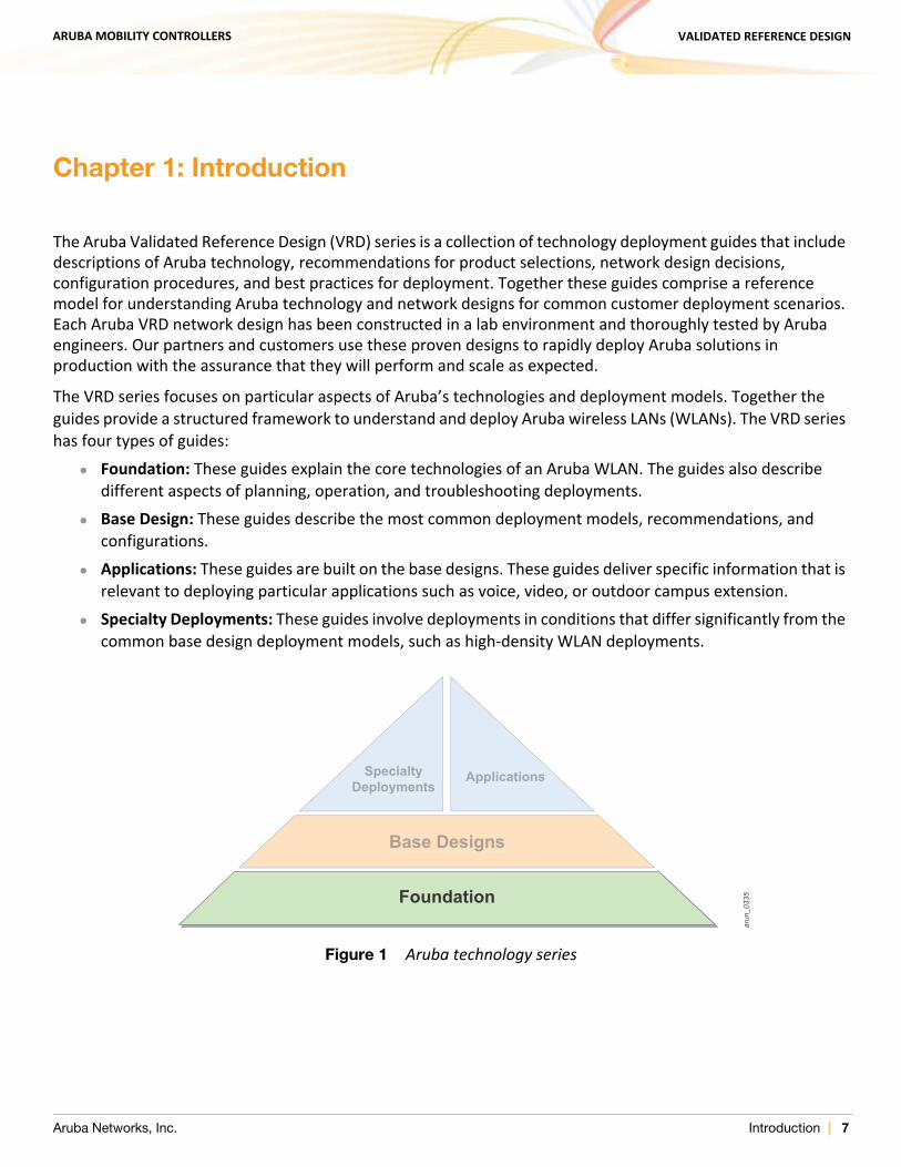
The VRD series focuses on particular aspects of Aruba’s technologies and deployment models. Together the guides provide a structured framework to understand and deploy Aruba wireless LANs (WLANs). The VRD series has four types of guides:
Foundation: These guides explain the core technologies of an Aruba WLAN. The guides also describe different aspects of planning, operation, and troubleshooting deployments.
Base Design: These guides describe the most common deployment models, recommendations, and configurations.
Applications: These guides are built on the base designs. These guides deliver specific information that is relevant to deploying particular applications such as voice, video, or outdoor campus extension.
Specialty Deployments: These guides involve deployments in conditions that differ significantly from the common base design deployment models, such as high-density WLAN deployments.
Figure 1 Aruba technology series
arun
_033
5Foundation
Base Designs
SpecialtyDeployments
Applications
Aruba Networks, Inc. Introduction | 7
ARUBA MOBILITY CONTROLLERS VALIDATED REFERENCE DESIGN
This guide covers Aruba Mobility Controllers and is considered part of the foundation guides within the VRD core technologies series. This guide describes these general topics:
Operating modes for the mobility controller Licensing Forwarding modes Logical and physical deployment Redundancy How to select the appropriate mobility controller based on scalability requirements
This guide will help you understand the capabilities and options you have when deploying an Aruba Mobility Controller. Other guides in the series will build specific deployments using the information in this guide.
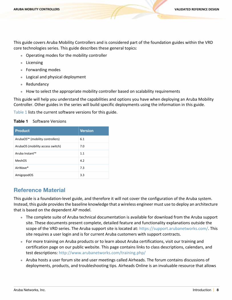
Table 1 lists the current software versions for this guide.
Reference MaterialThis guide is a foundation-level guide, and therefore it will not cover the configuration of the Aruba system. Instead, this guide provides the baseline knowledge that a wireless engineer must use to deploy an architecture that is based on the dependent AP model.
The complete suite of Aruba technical documentation is available for download from the Aruba support site. These documents present complete, detailed feature and functionality explanations outside the scope of the VRD series. The Aruba support site is located at: https://support.arubanetworks.com/. This site requires a user login and is for current Aruba customers with support contracts.
For more training on Aruba products or to learn about Aruba certifications, visit our training and certification page on our public website. This page contains links to class descriptions, calendars, and test descriptions: http://www.arubanetworks.com/training.php/
Aruba hosts a user forum site and user meetings called Airheads. The forum contains discussions of deployments, products, and troubleshooting tips. Airheads Online is an invaluable resource that allows
Table 1 Software Versions
Product Version
ArubaOS™ (mobility controllers) 6.1
ArubaOS (mobility access switch) 7.0
Aruba Instant™ 1.1
MeshOS 4.2
AirWave® 7.3
AmigopodOS 3.3
Aruba Networks, Inc. Introduction | 8
ARUBA MOBILITY CONTROLLERS VALIDATED REFERENCE DESIGN
network administrators to interact with each other and Aruba experts. Announcements for Airheads in-person meetings are also available on the site: http://airheads.arubanetworks.com/
The VRD series assumes a working knowledge of Wi-Fi®, and more specifically dependent AP, or controller based, architectures. For more information about wireless technology fundamentals, visit the Certified Wireless Network Professional (CWNP) site at http://www.cwnp.com/
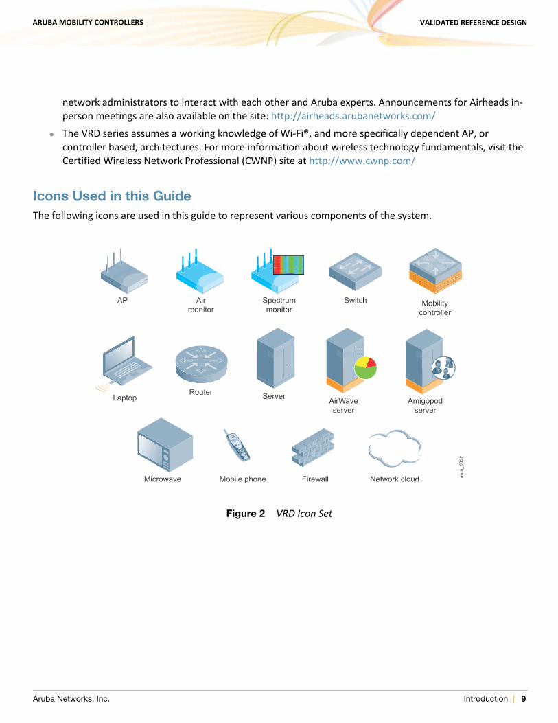
Icons Used in this GuideThe following icons are used in this guide to represent various components of the system.
Figure 2 VRD Icon Set
Airmonitor
Microwave Mobile phone Firewall Network cloud
AP
Laptop
Spectrummonitor
Mobilitycontroller
Switch
RouterAirWaveserver
Server Amigopodserver
arun
_033
2
Aruba Networks, Inc. Introduction | 9

ARUBA MOBILITY CONTROLLERS VALIDATED REFERENCE DESIGN
Aruba Networks, Inc. Introduction | 10
ARUBA MOBILITY CONTROLLERS VALIDATED REFERENCE DESIGN
Chapter 2: Summary of Recommendations
This section summarizes the recommendations made throughout the rest of the guide and is intended to be used as a quick reference. It is highly recommended that if you are new to this material you skip to the next chapter and continue reading from there.
Mobility Controller Licensing This section summarizes the recommendations on software licensing.
Matching AP-Based Licenses
AP-based licenses should always have the same AP count when in use. These licenses are AP capacity, PEF-NG, and RFProtect. Backup mobility controllers must have a license for each AP that the backup will terminate. The licensing rule is:
AP Capacity = PEF-NG = RFProtect
Only licenses that enable required functionality should be purchased. For example, xSec is primarily deployed only in government and military installations, and it is not required unless it will be in use at the organization. Before purchasing any licenses, check that the functionality enabled by the license will be used within the organization.
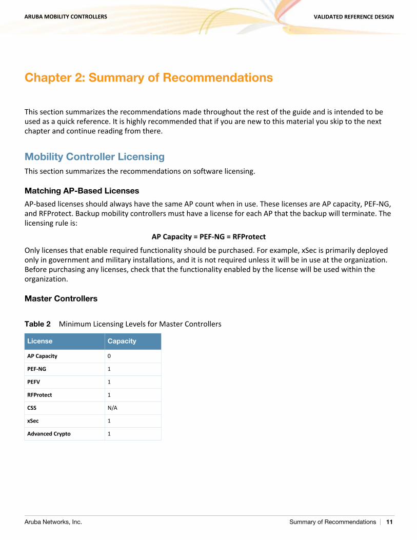
Master Controllers
Table 2 Minimum Licensing Levels for Master Controllers
License Capacity
AP Capacity 0
PEF-NG 1
PEFV 1
RFProtect 1
CSS N/A
xSec 1
Advanced Crypto 1
Aruba Networks, Inc. Summary of Recommendations | 11
ARUBA MOBILITY CONTROLLERS VALIDATED REFERENCE DESIGN
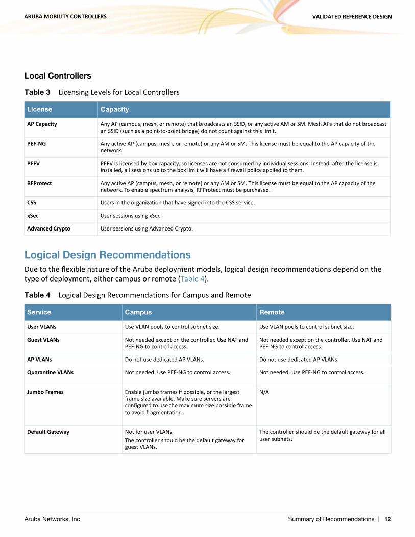
Local Controllers
Logical Design Recommendations Due to the flexible nature of the Aruba deployment models, logical design recommendations depend on the type of deployment, either campus or remote (Table 4).
Table 3 Licensing Levels for Local Controllers
License Capacity
AP Capacity Any AP (campus, mesh, or remote) that broadcasts an SSID, or any active AM or SM. Mesh APs that do not broadcast an SSID (such as a point-to-point bridge) do not count against this limit.
PEF-NG Any active AP (campus, mesh, or remote) or any AM or SM. This license must be equal to the AP capacity of the network.
PEFV PEFV is licensed by box capacity, so licenses are not consumed by individual sessions. Instead, after the license is installed, all sessions up to the box limit will have a firewall policy applied to them.
RFProtect Any active AP (campus, mesh, or remote) or any AM or SM. This license must be equal to the AP capacity of the network. To enable spectrum analysis, RFProtect must be purchased.
CSS Users in the organization that have signed into the CSS service.
xSec User sessions using xSec.
Advanced Crypto User sessions using Advanced Crypto.
Table 4 Logical Design Recommendations for Campus and Remote
Service Campus Remote
User VLANs Use VLAN pools to control subnet size. Use VLAN pools to control subnet size.
Guest VLANs Not needed except on the controller. Use NAT and PEF-NG to control access.
Not needed except on the controller. Use NAT and PEF-NG to control access.
AP VLANs Do not use dedicated AP VLANs. Do not use dedicated AP VLANs.
Quarantine VLANs Not needed. Use PEF-NG to control access. Not needed. Use PEF-NG to control access.
Jumbo Frames Enable jumbo frames if possible, or the largest frame size available. Make sure servers are configured to use the maximum size possible frame to avoid fragmentation.
N/A
Default Gateway Not for user VLANs.The controller should be the default gateway for guest VLANs.
The controller should be the default gateway for all user subnets.
Aruba Networks, Inc. Summary of Recommendations | 12
ARUBA MOBILITY CONTROLLERS VALIDATED REFERENCE DESIGN
Campus Logical Design Recommendations
User VLANs: If more than one user VLAN is required, Aruba recommends that VLAN pools be used to distribute users more evenly across the pools. By using multiple VLANs in a VLAN pool, the size of broadcast domains are reduced and the configuration is simplified for the network manager. Aruba recommends the use of class C (/24) subnets, and the subnets across all VLANs in a pool should be the same size.
Guest VLANs: Though guest VLANs are common in many deployments for historical reasons, guest VLANs that cross the internal network to the DMZ are not needed in the Aruba system. Aruba recommends that organizations consider deploying guests on a nonroutable network with a VLAN that exists only on the Aruba Mobility Controller. Consider having the mobility controller act as the DHCP and NAT server for this self-contained VLAN. The guest role should be locked down so that guest users have limited or preferably no access to internal resources and only limited access to Internet protocols.
AP VLANs: Aruba strongly recommends that edge access VLANs should not be dedicated to APs except in environments where 802.1X is a requirement on the wired edge. The APs should use the existing edge VLANs as long as they have the ability to reach the mobility controller. Deploying the APs in the existing VLANs allows for the full use of the Aruba rogue detection capabilities. If 802.1X is in use on the wired edge, Aruba recommends placing APs in a VLAN that is routable only to the interface of the mobility controller.The other exception to this rule is for AMs. The AMs can be connected to a trunk port that contains all VLANs that appear on any wired access port within range of the AM. This connection is used for the AM to do wireless-to-wired correlation when it is tracking rogue APs. Alternatively, all access VLANs can be trunked to the mobility controller and wired correlation can be performed at that point.
Quarantine VLANs: Aruba also recommends against the use of a quarantine VLAN unless it is required by security policy. Instead, Aruba recommends that the integrated firewall and user roles are used to lock down users with a quarantine role. The locations and communications capabilities of the quarantined device are limited more effectively with a quarantine role than with a shared VLAN.
Default router: In most campus environments, the Aruba Mobility Controller is deployed as a Layer 2 device to provide mobile access and security policy, but not to act as the default gateway for the user subnets. The default gateways typically already exist and are already set in DHCP scopes. To continue to use these devices provides the least disruption to the existing network. Aruba does recommend that the mobility controller act as default gateway and DHCP server for guest VLANs in all deployments where the VLAN exists only on the mobility controller and for user VLANs in remote access deployments. In these deployments, the mobility controller is the only networking device with clear visibility into the user subnets, and as such should be deployed as the default gateway.
Aruba Networks, Inc. Summary of Recommendations | 13
ARUBA MOBILITY CONTROLLERS VALIDATED REFERENCE DESIGN
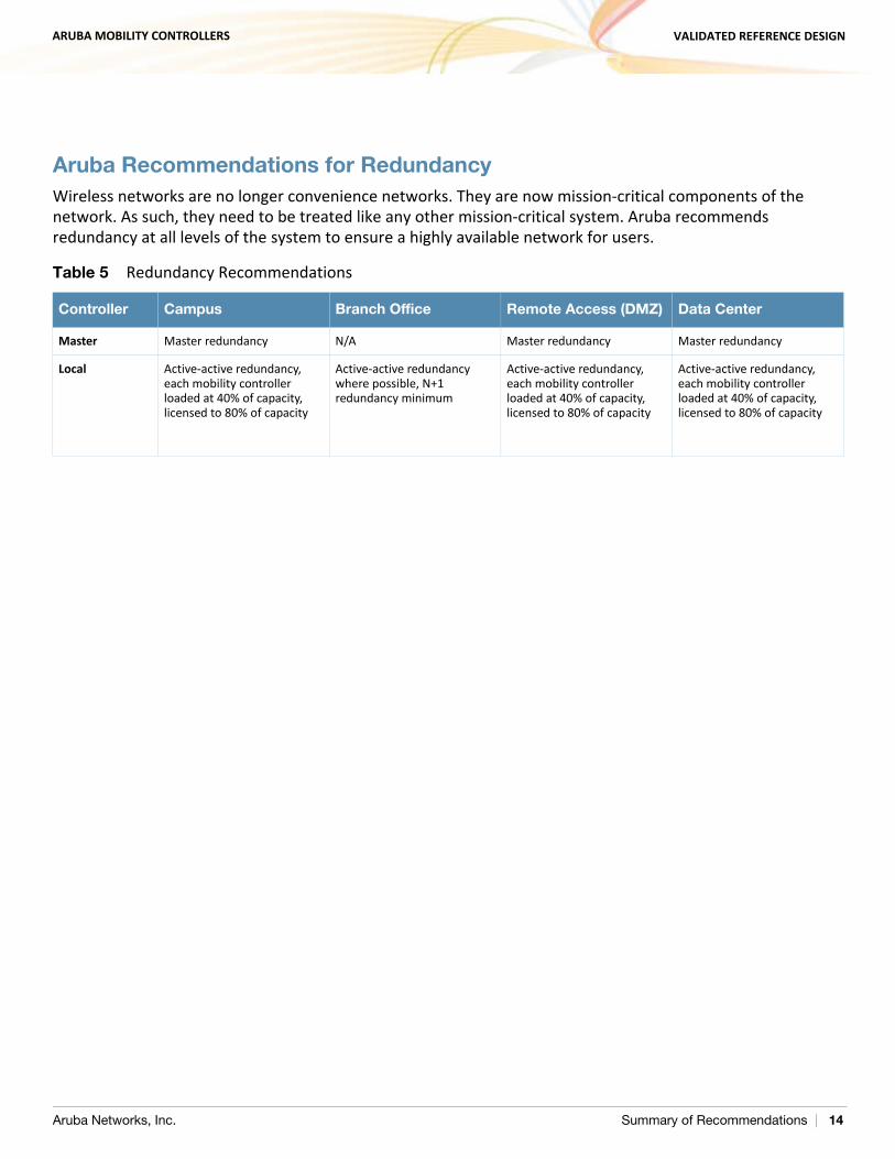
Aruba Recommendations for RedundancyWireless networks are no longer convenience networks. They are now mission-critical components of the network. As such, they need to be treated like any other mission-critical system. Aruba recommends redundancy at all levels of the system to ensure a highly available network for users.
Table 5 Redundancy Recommendations
Controller Campus Branch Office Remote Access (DMZ) Data Center
Master Master redundancy N/A Master redundancy Master redundancy
Local Active-active redundancy, each mobility controller loaded at 40% of capacity, licensed to 80% of capacity
Active-active redundancy where possible, N+1 redundancy minimum
Active-active redundancy, each mobility controller loaded at 40% of capacity, licensed to 80% of capacity
Active-active redundancy, each mobility controller loaded at 40% of capacity, licensed to 80% of capacity
Aruba Networks, Inc. Summary of Recommendations | 14
ARUBA MOBILITY CONTROLLERS VALIDATED REFERENCE DESIGN
Chapter 3: Understanding the Aruba Mobility Controller
The Aruba Mobility Controller is the heart of the Aruba dependent access point (AP) WLAN architecture. The mobility controller is responsible for many of the operations that traditionally would be handled by an autonomous AP, and it delivers additional functionality for control, security, operation, and troubleshooting. The functionality that the mobility controller provides includes:
Acting as a user-based stateful firewall Terminating user-encrypted sessions from wireless devices Performing Layer 2 switching and Layer 3 routing Providing clientless Layer 3 mobility Acting as an IPsec virtual private network (VPN) concentrator for site-to-site and client-based VPNs Providing certificate-based IPsec security to protect control channel information Terminating Internet-based remote APs (RAPs) Providing wired firewall services Performing user authentication with 802.1X and captive portal authentication, among others Providing guest access and captive portal services Provisioning services Providing advanced RF services with Adaptive Radio Management™ (ARM™) and spectrum analysis Providing location services and RF coverage “heat maps” of the deployment Performing rogue detection and containment Providing self-contained management by way of a master/local hierarchy with one controller pushing
configuration to other mobility controllers to reduce administrative overhead Delivering AP software updates automatically when the mobility controller is upgraded
This level of seamless, integrated functionality eliminates many of the challenges experienced with traditional systems integration of these services. Network administrators need to learn only one interface, which reduces deployment complexity and speeds problem resolution across a broad range of solutions.
Aruba Networks, Inc. Understanding the Aruba Mobility Controller | 15
ARUBA MOBILITY CONTROLLERS VALIDATED REFERENCE DESIGN
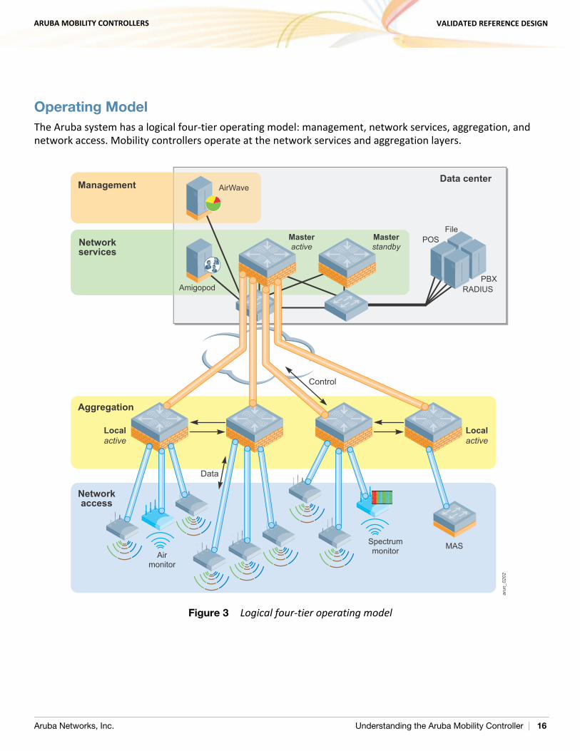
Operating ModelThe Aruba system has a logical four-tier operating model: management, network services, aggregation, and network access. Mobility controllers operate at the network services and aggregation layers.
Figure 3 Logical four-tier operating model
arun_0202
Spectrummonitor MAS
Airmonitor
Control
Data
Localactive
Localactive
Masterstandby
Data center
MasteractiveNetwork
services
Management
Aggregation
Networkaccess
AirWave
POSFile
RADIUSPBX
Amigopod
Aruba Networks, Inc. Understanding the Aruba Mobility Controller | 16
ARUBA MOBILITY CONTROLLERS VALIDATED REFERENCE DESIGN
Management
AirWave® provides a single point of management for the WLAN, access switches, and VPN clients connected to Aruba controllers. The core AirWave application is AirWave Management Platform™ (AMP™), which gathers data from network elements, reports on historical trends, analyzes data for real-time alerts, detects rogue access points, and creates a visualization of the RF network. AirWave Master Console™ provides a central reporting, searching, and alerting interface when multiple AMP servers are deployed. AirWave Failover provides redundancy for one or more AirWave servers in the case of a server failure.
Network Services
The network services layer provides a control plane for the Aruba system that spans the physical geography of the wired network. This layer consists of master mobility controllers and Amigopod™ appliances. The control plane does not directly interact with user traffic or APs. Instead, the control plane provides services such as white list coordination, valid AP lists, control plane security (CPsec) certificates, wireless intrusion detection and coordination, and RADIUS or AAA proxy. Amigopod provides advanced guest access services.
Aggregation
The aggregation layer is the interconnect point where the AP, AM, wired AP, and RAP traffic that is destined for the enterprise network is aggregated. This layer provides a logical point for enforcement of roles and policies on centralized traffic that enters or exits the enterprise LAN.
Network Access
The network access layer is comprised of APs, AMs, wired APs, RAPs, mobility access switches (MASs), and physical controller ports that work together with the aggregation layer controllers to overlay the Aruba system. When policy-based or bridge forwarding modes are used, firewall policies are applied at the AP. Bridge mode traffic never reaches the controller, and split-tunnel traffic is forwarded only to the aggregation layer for enterprise destinations and traffic not directly bridged.
Controller Model OverviewThe mobility controllers are available as network appliances and chassis-based systems that scale to meet the needs of the largest organizations. This section briefly introduces the mobility controller models. The Mobility Controller Product Line Matrix contains the complete statistics for each model, and is available at http://www.arubanetworks.com/vrd.
Aruba Networks, Inc. Understanding the Aruba Mobility Controller | 17
ARUBA MOBILITY CONTROLLERS VALIDATED REFERENCE DESIGN
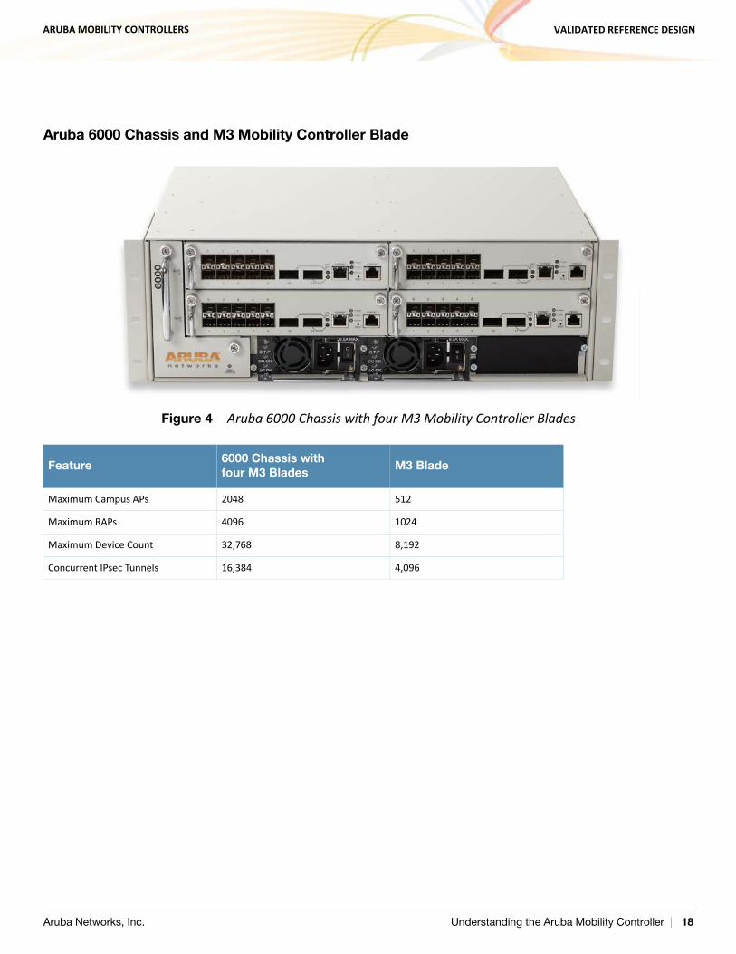
Aruba 6000 Chassis and M3 Mobility Controller Blade
Figure 4 Aruba 6000 Chassis with four M3 Mobility Controller Blades
Feature6000 Chassis with four M3 Blades
M3 Blade
Maximum Campus APs 2048 512
Maximum RAPs 4096 1024
Maximum Device Count 32,768 8,192
Concurrent IPsec Tunnels 16,384 4,096
Aruba Networks, Inc. Understanding the Aruba Mobility Controller | 18
ARUBA MOBILITY CONTROLLERS VALIDATED REFERENCE DESIGN
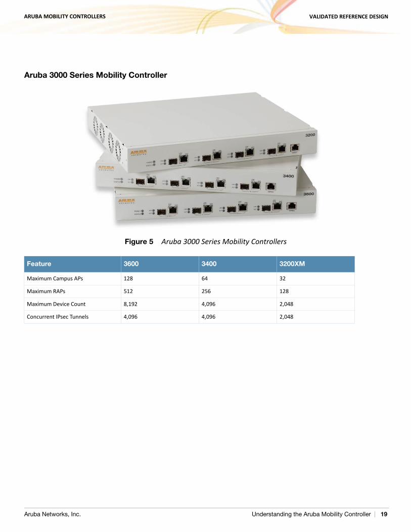
Aruba 3000 Series Mobility Controller
Figure 5 Aruba 3000 Series Mobility Controllers
Feature 3600 3400 3200XM
Maximum Campus APs 128 64 32
Maximum RAPs 512 256 128
Maximum Device Count 8,192 4,096 2,048
Concurrent IPsec Tunnels 4,096 4,096 2,048
Aruba Networks, Inc. Understanding the Aruba Mobility Controller | 19
ARUBA MOBILITY CONTROLLERS VALIDATED REFERENCE DESIGN
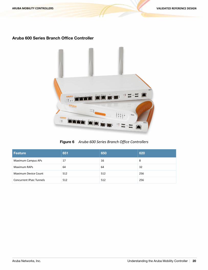
Aruba 600 Series Branch Office Controller
Figure 6 Aruba 600 Series Branch Office Controllers
Feature 651 650 620
Maximum Campus APs 17 16 8
Maximum RAPs 64 64 32
Maximum Device Count 512 512 256
Concurrent IPsec Tunnels 512 512 256
Aruba Networks, Inc. Understanding the Aruba Mobility Controller | 20
ARUBA MOBILITY CONTROLLERS VALIDATED REFERENCE DESIGN
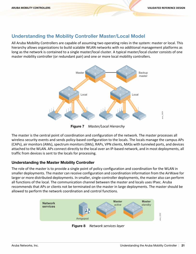
Understanding the Mobility Controller Master/Local Model All Aruba Mobility Controllers are capable of assuming two operating roles in the system: master or local. This hierarchy allows organizations to build scalable WLAN networks with no additional management platforms as long as the network is contained to a single master/local cluster. A typical master/local cluster consists of one master mobility controller (or redundant pair) and one or more local mobility controllers.
Figure 7 Master/Local Hierarchy
The master is the central point of coordination and configuration of the network. The master processes all wireless security events and sends policy-based configuration to the locals. The locals manage the campus APs (CAPs), air monitors (AMs), spectrum monitors (SMs), RAPs, VPN clients, MASs with tunneled ports, and devices attached to the WLAN. APs connect directly to the local over an IP-based network, and in most deployments, all traffic from devices is sent to the locals for processing.
Understanding the Master Mobility Controller
The role of the master is to provide a single point of policy configuration and coordination for the WLAN in smaller deployments. The master can receive configuration and coordination information from the AirWave for larger or more distributed deployments. In smaller, single-controller deployments, the master also can perform all functions of the local. The communication channel between the master and locals uses IPsec. Aruba recommends that APs or clients not be terminated on the master in large deployments. The master should be allowed to perform the network coordination and control functions.
Figure 8 Network services layer
arun
_042
4
Master Backupmaster
Local Local
arun
_020
2
Masterstandby
MasteractiveNetwork
services
Amigopod
Aruba Networks, Inc. Understanding the Aruba Mobility Controller | 21
ARUBA MOBILITY CONTROLLERS VALIDATED REFERENCE DESIGN
Masters are responsible for the following functions in the WLAN: Policy configuration: Configuration in the Aruba solution is split between policy and local configurations.
Local configuration relates to physical interfaces, IP networking, and VLANs, which are different for each mobility controller. Policy configuration is centered on the operation of APs and users, including AP settings such as the SSID name, encryption, regulatory domain, channel, power, and ARM settings. Policy configuration extends beyond APs and also covers user authentication, firewall policy, mobility domains (IP mobility), IPsec, and system management. The policy is pushed to all locals in the form of profiles, and profiles combine to create the configuration for the dependent APs.
AP white lists: Two types of white lists exist in the system, one for RAPs and one for CAPs that use CPsec. These lists determine which APs can connect to the mobility controllers. Unauthorized devices are prevented from connecting to the network.
Wireless security coordination: Wireless intrusion prevention activities involve looking for rogue (unauthorized) APs and monitoring for attacks on the WLAN infrastructure or clients. The master processes all data collected by Aruba APs and AMs. Instructions to disable a rogue AP or blacklist a client from the network are issued through the master.
Valid AP list: All mobility controllers in the network must also know all legitimate APs that operate on the WLAN. These APs must be added to the valid AP list. This list prevents valid APs from being falsely flagged as rogue APs. This is important when APs that are attached to two different locals are close enough to hear each other’s transmissions. The valid AP list helps ARM to differentiate between APs that belong to the network and those that are neighbors. Unlike traditional wireless intrusion detection system (WIDS) solutions, the master controller automatically generates the valid AP list without network administrator intervention. All Aruba APs are automatically learned and added to the list, but valid third-party APs must be added manually. If more than one master/local cluster exists, AirWave should be deployed to coordinate APs between clusters.
RF visualization: The Aruba RF visualization tools provide a real-time view of the network coverage. This information is based on the AP channel and power settings and the data collected from AMs and APs listening to transmissions during their scanning periods. This information provides a real-time picture of the RF coverage as heard by the APs.
Location: Locating users in the WLAN is more difficult with mobile clients and IP mobility. The IP address of the client is no longer synonymous with location. The Aruba WLAN scans off of the configured channel, so it is possible to hear clients operating on other channels. This information can then be used to triangulate users and rogue devices to within a small area. This information is displayed on the master and allows for devices to be located quickly. This speed is critically important for physical security and advanced services such as E911 calling.
Initial AP configuration: When an AP first boots up, it contacts its master to receive the configuration generated by the master. The master compares the AP information and determines its group assignment, and then redirects that AP to the proper local.
Control plane security: When CPsec is enabled, the master generates the self-signed certificate and acts as the certificate authority (CA) for the network. The master issues certificates to all locals in the
Aruba Networks, Inc. Understanding the Aruba Mobility Controller | 22
ARUBA MOBILITY CONTROLLERS VALIDATED REFERENCE DESIGN
network, which in turn certify APs. If more than one master exists in the network, the network administrator assigns a single master as the trust anchor for that network. The trust anchor issues certificates to the other master controllers in the network.
Authentication and roles: User authentication methods and role assignments are created on the master and then propagated to locals throughout the network. A database exists to authenticate users in small deployments or for guest access credentials that can be leveraged by all the mobility controllers in the network. Additionally, the master can proxy requests for the network to a RADIUS or LDAP server.
Understanding the Local Mobility Controller
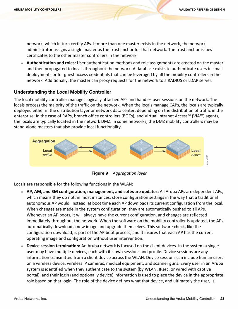
The local mobility controller manages logically attached APs and handles user sessions on the network. The locals process the majority of the traffic on the network. When the locals manage CAPs, the locals are typically deployed either in the distribution layer or network data center, depending on the distribution of traffic in the enterprise. In the case of RAPs, branch office controllers (BOCs), and Virtual Intranet Access™ (VIA™) agents, the locals are typically located in the network DMZ. In some networks, the DMZ mobility controllers may be stand-alone masters that also provide local functionality.
Figure 9 Aggregation layer
Locals are responsible for the following functions in the WLAN: AP, AM, and SM configuration, management, and software updates: All Aruba APs are dependent APs,
which means they do not, in most instances, store configuration settings in the way that a traditional autonomous AP would. Instead, at boot time each AP downloads its current configuration from the local. When changes are made in the system configuration, they are automatically pushed to all APs. Whenever an AP boots, it will always have the current configuration, and changes are reflected immediately throughout the network. When the software on the mobility controller is updated, the APs automatically download a new image and upgrade themselves. This software check, like the configuration download, is part of the AP boot process, and it insures that each AP has the current operating image and configuration without user intervention.
Device session termination: An Aruba network is focused on the client devices. In the system a single user may have multiple devices, each with it’s own sessions and profile. Device sessions are any information transmitted from a client device across the WLAN. Device sessions can include human users on a wireless device, wireless IP cameras, medical equipment, and scanner guns. Every user in an Aruba system is identified when they authenticate to the system (by WLAN, IPsec, or wired with captive portal), and their login (and optionally device) information is used to place the device in the appropriate role based on that login. The role of the device defines what that device, and ultimately the user, is
arun
_020
2
Localactive
Localactive
Aggregation
Aruba Networks, Inc. Understanding the Aruba Mobility Controller | 23
ARUBA MOBILITY CONTROLLERS VALIDATED REFERENCE DESIGN
allowed to do on the network. This definition is enforced by an ICSA1 certified stateful firewall, and a role-based policy is applied to every device.
ARM assignments and load balancing: Aruba ARM controls aspects of AP and client performance. All WLANs operate in unlicensed space, so the chance that something will interfere with transmissions is very high. Aruba has developed a system to work around interference automatically and help clients have a better operating experience. These features include automatically tuning the WLAN by configuring AP power and channel settings, as well as scanning for better channels and avoiding interference. ARM also handles AP load balancing and co-channel interference from other APs and clients. Airtime fairness ensures that slower-speed clients do not bring down the throughput of higher-speed clients. Using band steering, when the system detects a client that is capable of operating on the 5 GHz band (the majority of modern clients), the system automatically attempts to steer that client to the cleaner band. More information on ARM can be found in Aruba 802.11n Networks VRD available at http://www.arubanetworks.com/vrd.
RFProtect™ security enforcement and blacklisting: While the master handles the processing of security event information, the local directs the actions of the AMs for enforcement of wireless security policy. Enforcement can take different shapes, including containing rogue APs by performing denial-of-service (DoS) attacks wirelessly, ARP cache poisoning on the wire, shielding valid clients from connecting to rogue APs, and blacklisting clients so that they are unable to attach to the WLAN.
RFProtect spectrum analysis: When an AP is performing spectrum scanning, the visualizations of the RF data are generated on the local. This data is pushed to the client’s web browser and can be saved for later analysis.
CPsec AP certification: When CPsec is enabled in the WLAN, the AP and local mobility controller establish an IPsec tunnel between the two devices using certificates. The local is responsible for issuing these certificates and adding APs to the white list. When the AP boots up and tries to contact the local, the certificates are used to build an IPsec tunnel between the devices.
Mobility: Supports Layer 2 (VLAN) mobility and Layer 3 (IP) mobility, which allows users to roam seamlessly between APs on different mobility controllers without session interruption. This mobility is a key component to support VoIP sessions, where sessions must be preserved.
Quality of service (QoS): The locals support QoS on the wired and wireless side. This support includes translating DiffServ and ToS bits set on packets into Wi-Fi Multimedia™ (WMM®) markings and back. The Aruba Policy Enforcement Firewall™ (PEF™) also allows the administrator to mark packets with the appropriate level of QoS, and to change markings on packets entering the system.
1. ICSA labs provides vendor neutral testing of products and certifies them in compliance with a set of common tests and criteria. ICSA is on the web at http://www.icsalabs.com/
Aruba Networks, Inc. Understanding the Aruba Mobility Controller | 24
ARUBA MOBILITY CONTROLLERS VALIDATED REFERENCE DESIGN
Chapter 4: Controller Licensing
The ArubaOS™ base operating system contains many features and types of functionality that are needed for an enterprise WLAN network. Aruba uses a licensing mechanism to enable additional features and to enable AP capacity on controllers. By licensing functionality, organizations can deploy the network with the functionality to meet their specific requirements in a flexible and cost effective manner.
License DescriptionsFor complete descriptions of the features enabled by these licenses, visit the Aruba website at http://www.arubanetworks.com/products/arubaos/.
AP Capacity: AP capacity relates to how many APs, AMs, SMs, RAPs, and mesh points that serve clients can connect to a particular mobility controller. For mesh APs, where wireless is used for wired traffic backhaul, the mesh links that do not broadcast a client SSID are not counted against this license. If the AP acts as a mesh node and an access point for devices, the AP counts against the AP capacity license. When you plan for redundancy, the AP capacity must match the maximum number of APs that could potentially terminate on the backup mobility controller.
Policy Enforcement Firewall–Next Generation (PEF-NG): The Aruba PEF-NG module for ArubaOS provides identity-based controls. The controls enforce application-layer security, prioritization, traffic forwarding, and network performance policies for wired and wireless networks. Administrators can build a unified, integrated system for network policy enforcement by leveraging the open APIs of PEF-NG. External services such as content security appliances, network access control (NAC) policy engines, performance monitors, and authentication/authorization servers also can be leveraged by redirecting traffic and accepting authorization information from the external device. PEF-NG is licensed by AP count, and the number of licensed APs must be equal to the AP capacity license of the mobility controller. To enable PEF-NG on wired-only gateways, a single AP PEF-NG license is required.
Policy Enforcement Firewall–VPN (PEFV): The PEFV license provides the same features and functionality that PEF-NG does, but it is applied to users coming in over VPN connections as opposed to wireless users. The user role and policy are enforced on the mobility controller and thus only affects centralized traffic. This license is required for the Aruba VIA client. The PEFV license is purchased as a single license that enables the functionality up to the full user capacity of the mobility controller.
RFProtect: The Aruba RFProtect module protects the network against wireless threats to network security by incorporating multiple scanning and containment features into the network infrastructure. Integration of WLAN and security provides wireless network visibility and simplicity of operation for network administrators, and thwarts malicious wireless attacks, impersonations, and unauthorized intrusions. Clients and APs are already a part of the system, so no valid AP or user list must be manually maintained because the network already knows which users and devices belong there. Additionally, many of the traditional features and attacks that are reported by traditional WIDS vendors are
Aruba Networks, Inc. Controller Licensing | 25
ARUBA MOBILITY CONTROLLERS VALIDATED REFERENCE DESIGN
unnecessary due to the RFProtect integration with the WLAN itself. RFProtect is licensed by AP count, and the number of licensed APs must be equal to the AP capacity license of the mobility controller.
Content Security Service (CSS): Aruba CSS provides cloud-based security for branch offices and teleworkers. CSS seamlessly integrates with the RAP and BOC product families to provide high-throughput, low-latency content security with centralized reporting and management. CSS leverages data centers around the world and provides complete protection including advanced URL filtering, P2P control, antivirus and antimalware, botnet detection, and data loss prevention. High-speed web logs in CSS provide a flexible and powerful way to view broad trends and per-user drill-downs of Internet activity. CSS licensing is based on three components: total user count, feature bundles, and contract length (1 or 3 years). The CSS licenses are installed on the cloud-based service platform.
xSec™ (XSC): xSec is a highly secure data link layer (Layer 2) protocol that provides a unified framework for securing all wired and wireless connections using strong encryption and authentication. xSec provides a Federal Information Processing Standard (FIPS)-compliant mechanism to provide identity-based security to government agencies and commercial entities that need to transmit extremely sensitive information over wireless networks. xSec provides greater security than other Layer 2 encryption technologies through the use of longer keys, FIPS-validated encryption algorithms (AES-CBC-256 with HMAC-SHA1), and the encryption of Layer 2 header information that includes MAC addresses. xSec was jointly developed by Aruba and Funk Software®, which is a division of Juniper Networks®. xSec is licensed on a per-user basis.
ArubaOS Advanced Cryptography (ACR): The ACR module brings Suite B cryptography to Aruba Mobility Controllers, which creates a secure and affordable unified access network that enables mobility for highly sensitive and classified networks. Approved by the US National Security Agency (NSA), Suite B is a set of publicly available algorithms that serve as the cryptographic base for both unclassified information and most classified information. The NSA has authorized the use of Suite B to facilitate the use of commercial technology for mobility as well as sharing of sensitive and classified information among disparate departments. ACR is licensed on a per-user basis.
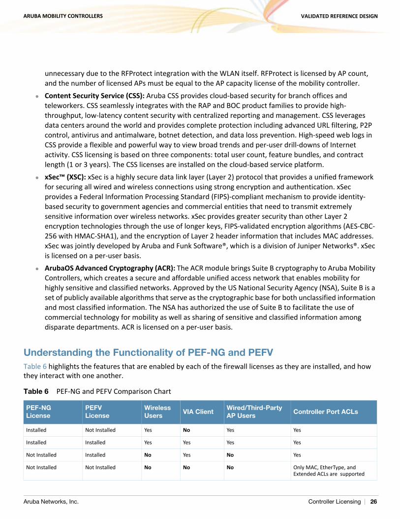
Understanding the Functionality of PEF-NG and PEFVTable 6 highlights the features that are enabled by each of the firewall licenses as they are installed, and how they interact with one another.
Table 6 PEF-NG and PEFV Comparison Chart
PEF-NGLicense
PEFVLicense
WirelessUsers
VIA ClientWired/Third-Party AP Users
Controller Port ACLs
Installed Not Installed Yes No Yes Yes
Installed Installed Yes Yes Yes Yes
Not Installed Installed No Yes No Yes
Not Installed Not Installed No No No Only MAC, EtherType, and Extended ACLs are supported
Aruba Networks, Inc. Controller Licensing | 26
ARUBA MOBILITY CONTROLLERS VALIDATED REFERENCE DESIGN
Licensing Requirements and RecommendationsDifferent license capacities are required for master and local mobility controllers. Each license type should be reviewed to determine if the features and functionality meet the goals of the organization. With that information it is possible to determine the required feature licensing levels.
Matching AP-Based Licenses
AP-based licenses should always have the same AP count when in use. These licenses are AP capacity, PEF-NG, and RFProtect. Backup mobility controllers must have a license for each AP that the backup will terminate. The licensing rule is:
AP Capacity = PEF-NG = RFProtect
For example, if a 64 AP capacity license was purchased and the organization wants to deploy PEF-NG and RFProtect, those licenses should be purchased to match the 64 AP capacity. The final license count would be 64 AP capacity, 64 PEF-NG, and 64 RFProtect. There is one exception to this rule, and that is for the master. The master does not require AP licenses if it is not terminating APs.
Licensing Requirements for Master Mobility Controllers
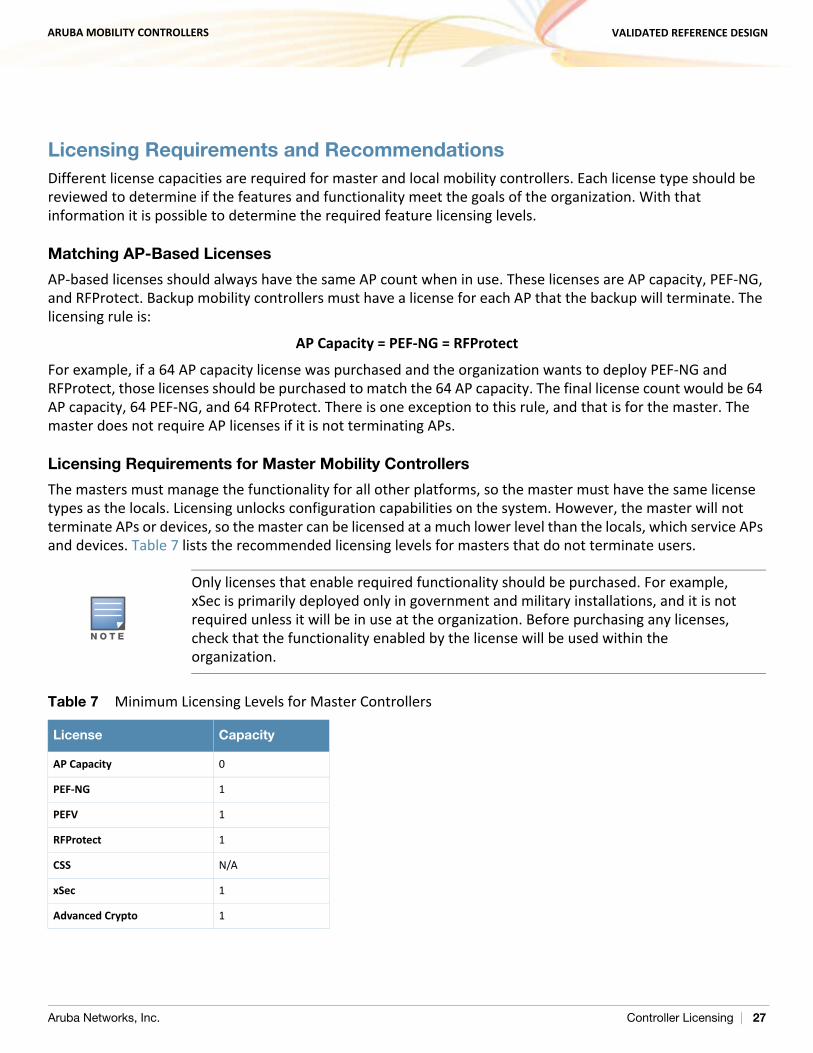
The masters must manage the functionality for all other platforms, so the master must have the same license types as the locals. Licensing unlocks configuration capabilities on the system. However, the master will not terminate APs or devices, so the master can be licensed at a much lower level than the locals, which service APs and devices. Table 7 lists the recommended licensing levels for masters that do not terminate users.
N O T E
Only licenses that enable required functionality should be purchased. For example, xSec is primarily deployed only in government and military installations, and it is not required unless it will be in use at the organization. Before purchasing any licenses, check that the functionality enabled by the license will be used within the organization.
Table 7 Minimum Licensing Levels for Master Controllers
License Capacity
AP Capacity 0
PEF-NG 1
PEFV 1
RFProtect 1
CSS N/A
xSec 1
Advanced Crypto 1
Aruba Networks, Inc. Controller Licensing | 27
ARUBA MOBILITY CONTROLLERS VALIDATED REFERENCE DESIGN
Licensing Requirements for Local Mobility Controllers
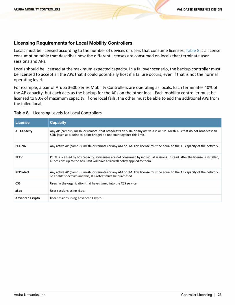
Locals must be licensed according to the number of devices or users that consume licenses. Table 8 is a license consumption table that describes how the different licenses are consumed on locals that terminate user sessions and APs.
Locals should be licensed at the maximum expected capacity. In a failover scenario, the backup controller must be licensed to accept all the APs that it could potentially host if a failure occurs, even if that is not the normal operating level.
For example, a pair of Aruba 3600 Series Mobility Controllers are operating as locals. Each terminates 40% of the AP capacity, but each acts as the backup for the APs on the other local. Each mobility controller must be licensed to 80% of maximum capacity. If one local fails, the other must be able to add the additional APs from the failed local.
Table 8 Licensing Levels for Local Controllers
License Capacity
AP Capacity Any AP (campus, mesh, or remote) that broadcasts an SSID, or any active AM or SM. Mesh APs that do not broadcast an SSID (such as a point-to-point bridge) do not count against this limit.
PEF-NG Any active AP (campus, mesh, or remote) or any AM or SM. This license must be equal to the AP capacity of the network.
PEFV PEFV is licensed by box capacity, so licenses are not consumed by individual sessions. Instead, after the license is installed, all sessions up to the box limit will have a firewall policy applied to them.
RFProtect Any active AP (campus, mesh, or remote) or any AM or SM. This license must be equal to the AP capacity of the network. To enable spectrum analysis, RFProtect must be purchased.
CSS Users in the organization that have signed into the CSS service.
xSec User sessions using xSec.
Advanced Crypto User sessions using Advanced Crypto.
Aruba Networks, Inc. Controller Licensing | 28
ARUBA MOBILITY CONTROLLERS VALIDATED REFERENCE DESIGN
Chapter 5: Mobility Controller Operation
Mobility controllers centralize many of the functions that would previously have been pushed to the edge of the network. Understanding the available options will help the network administrator build an effective Aruba WLAN.
User VLANsThe VLANs that support user traffic and that the client device uses to receive its IP addressing information are not always that same as the VLAN that the AP is plugged in to. In many cases, the user VLAN has nothing to do with the VLAN that the AP is connecting through. The user VLAN assignment varies depending on the forwarding mode, so each forwarding mode is described here.
User VLANs in Tunnel and Decrypt-Tunnel Modes
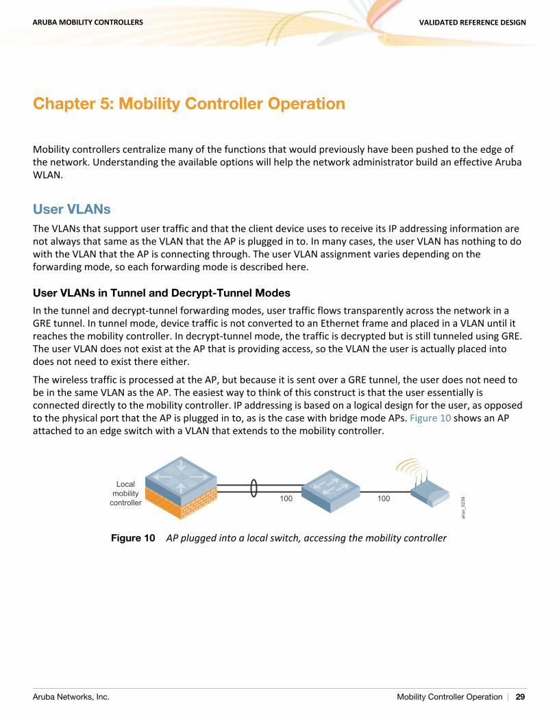
In the tunnel and decrypt-tunnel forwarding modes, user traffic flows transparently across the network in a GRE tunnel. In tunnel mode, device traffic is not converted to an Ethernet frame and placed in a VLAN until it reaches the mobility controller. In decrypt-tunnel mode, the traffic is decrypted but is still tunneled using GRE. The user VLAN does not exist at the AP that is providing access, so the VLAN the user is actually placed into does not need to exist there either.
The wireless traffic is processed at the AP, but because it is sent over a GRE tunnel, the user does not need to be in the same VLAN as the AP. The easiest way to think of this construct is that the user essentially is connected directly to the mobility controller. IP addressing is based on a logical design for the user, as opposed to the physical port that the AP is plugged in to, as is the case with bridge mode APs. Figure 10 shows an AP attached to an edge switch with a VLAN that extends to the mobility controller.
Figure 10 AP plugged into a local switch, accessing the mobility controller
Localmobility
controller 100 100
arun
_023
9
Aruba Networks, Inc. Mobility Controller Operation | 29
ARUBA MOBILITY CONTROLLERS VALIDATED REFERENCE DESIGN
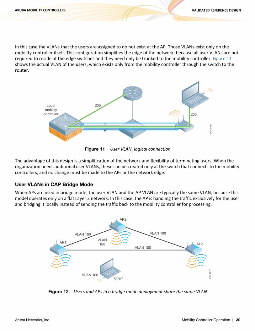
In this case the VLANs that the users are assigned to do not exist at the AP. Those VLANs exist only on the mobility controller itself. This configuration simplifies the edge of the network, because all user VLANs are not required to reside at the edge switches and they need only be trunked to the mobility controller. Figure 11 shows the actual VLAN of the users, which exists only from the mobility controller through the switch to the router.
Figure 11 User VLAN, logical connection
The advantage of this design is a simplification of the network and flexibility of terminating users. When the organization needs additional user VLANs, these can be created only at the switch that connects to the mobility controllers, and no change must be made to the APs or the network edge.
User VLANs in CAP Bridge Mode
When APs are used in bridge mode, the user VLAN and the AP VLAN are typically the same VLAN, because this model operates only on a flat Layer 2 network. In this case, the AP is handling the traffic exclusively for the user and bridging it locally instead of sending the traffic back to the mobility controller for processing.
Figure 12 Users and APs in a bridge mode deployment share the same VLAN
Localmobility
controller 200
200
arun
_024
0ar
un_0
241
ClientVLAN 100
VLAN 100
VLAN 100VLAN 100VLAN100AP1
AP2
AP3
Aruba Networks, Inc. Mobility Controller Operation | 30
ARUBA MOBILITY CONTROLLERS VALIDATED REFERENCE DESIGN
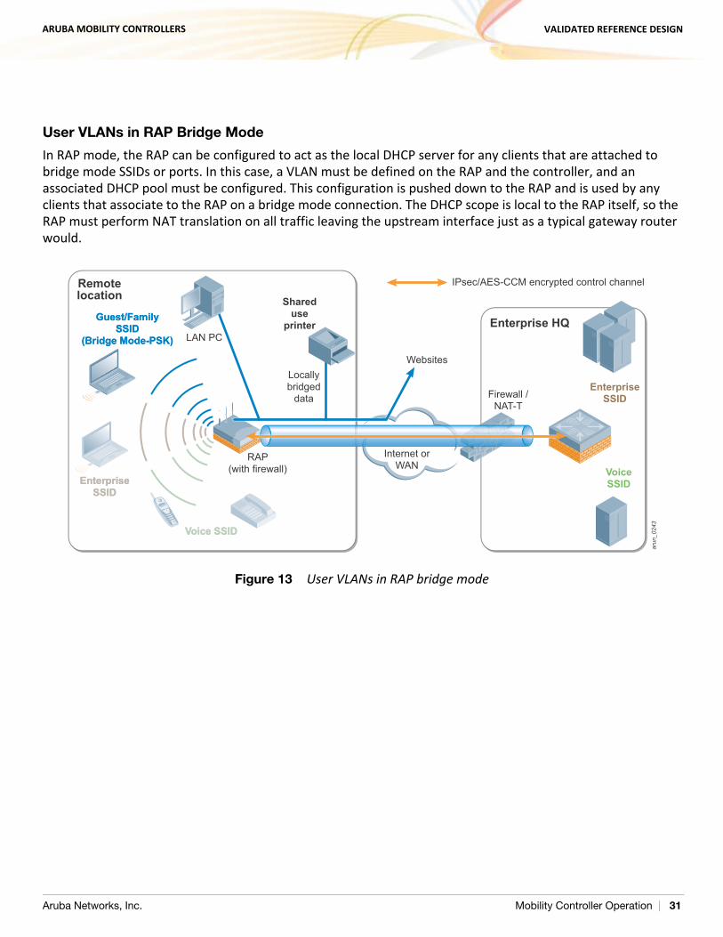
User VLANs in RAP Bridge Mode
In RAP mode, the RAP can be configured to act as the local DHCP server for any clients that are attached to bridge mode SSIDs or ports. In this case, a VLAN must be defined on the RAP and the controller, and an associated DHCP pool must be configured. This configuration is pushed down to the RAP and is used by any clients that associate to the RAP on a bridge mode connection. The DHCP scope is local to the RAP itself, so the RAP must perform NAT translation on all traffic leaving the upstream interface just as a typical gateway router would.
Figure 13 User VLANs in RAP bridge mode
arun
_024
3
VoiceSSID
EnterpriseSSID
IPsec/AES-CCM encrypted control channel
Enterprise HQ
Voice SSIDVoice SSID
Guest/FamilySSID
(Bridge Mode-PSK)
Guest/FamilySSID
(Bridge Mode-PSK)
EnterpriseSSID
EnterpriseSSID
LAN PC
RAP(with firewall)
RAP(with firewall)
Firewall /NAT-T
Internet orWAN
Websites
Remotelocation Shared
useprinter
Locallybridged
data
Aruba Networks, Inc. Mobility Controller Operation | 31
ARUBA MOBILITY CONTROLLERS VALIDATED REFERENCE DESIGN
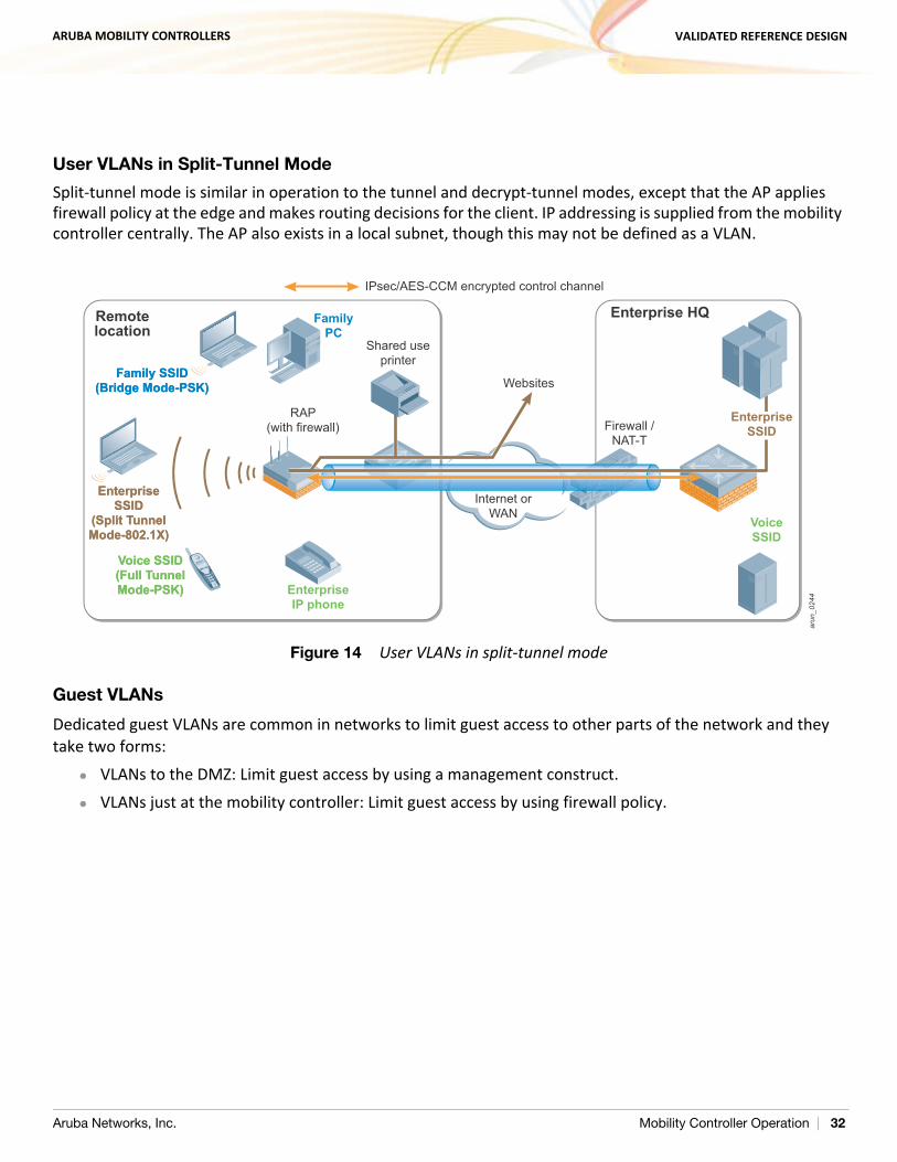
User VLANs in Split-Tunnel Mode
Split-tunnel mode is similar in operation to the tunnel and decrypt-tunnel modes, except that the AP applies firewall policy at the edge and makes routing decisions for the client. IP addressing is supplied from the mobility controller centrally. The AP also exists in a local subnet, though this may not be defined as a VLAN.
Figure 14 User VLANs in split-tunnel mode
Guest VLANs
Dedicated guest VLANs are common in networks to limit guest access to other parts of the network and they take two forms:
VLANs to the DMZ: Limit guest access by using a management construct. VLANs just at the mobility controller: Limit guest access by using firewall policy.
RN
SG
_124
arun
_024
4
VoiceSSID
EnterpriseSSID
IPsec/AES-CCM encrypted control channel
EnterpriseIP phone
Enterprise HQ
Voice SSID(Full TunnelMode-PSK)
Voice SSID(Full TunnelMode-PSK)
Family SSID(Bridge Mode-PSK)
Family SSID(Bridge Mode-PSK)
EnterpriseSSID
(Split TunnelMode-802.1X)
EnterpriseSSID
(Split TunnelMode-802.1X)
FamilyPC
RAP(with firewall)
RAP(with firewall) Firewall /
NAT-T
Internet orWAN
Websites
Shared useprinter
Remotelocation
Aruba Networks, Inc. Mobility Controller Operation | 32
ARUBA MOBILITY CONTROLLERS VALIDATED REFERENCE DESIGN
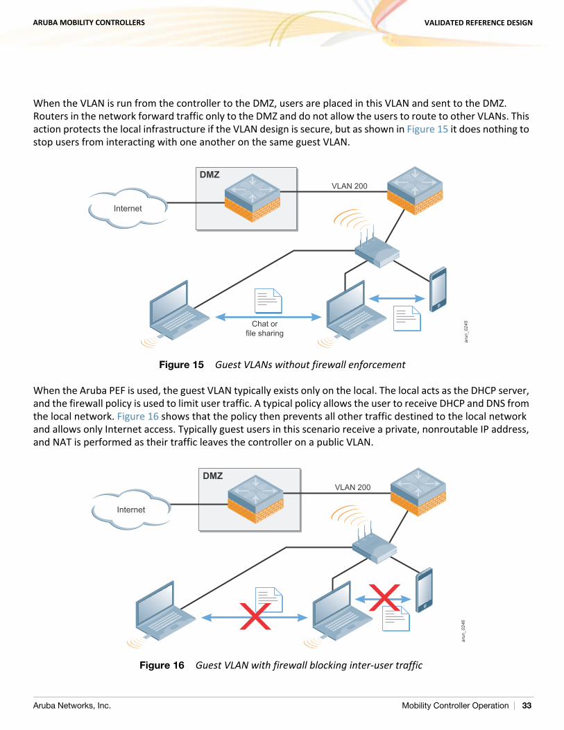
When the VLAN is run from the controller to the DMZ, users are placed in this VLAN and sent to the DMZ. Routers in the network forward traffic only to the DMZ and do not allow the users to route to other VLANs. This action protects the local infrastructure if the VLAN design is secure, but as shown in Figure 15 it does nothing to stop users from interacting with one another on the same guest VLAN.
Figure 15 Guest VLANs without firewall enforcement
When the Aruba PEF is used, the guest VLAN typically exists only on the local. The local acts as the DHCP server, and the firewall policy is used to limit user traffic. A typical policy allows the user to receive DHCP and DNS from the local network. Figure 16 shows that the policy then prevents all other traffic destined to the local network and allows only Internet access. Typically guest users in this scenario receive a private, nonroutable IP address, and NAT is performed as their traffic leaves the controller on a public VLAN.
Figure 16 Guest VLAN with firewall blocking inter-user traffic
arun
_024
5
Internet
VLAN 200
Chat orfile sharing
DMZ
arun
_024
6
Internet
VLAN 200DMZ
Aruba Networks, Inc. Mobility Controller Operation | 33
ARUBA MOBILITY CONTROLLERS VALIDATED REFERENCE DESIGN
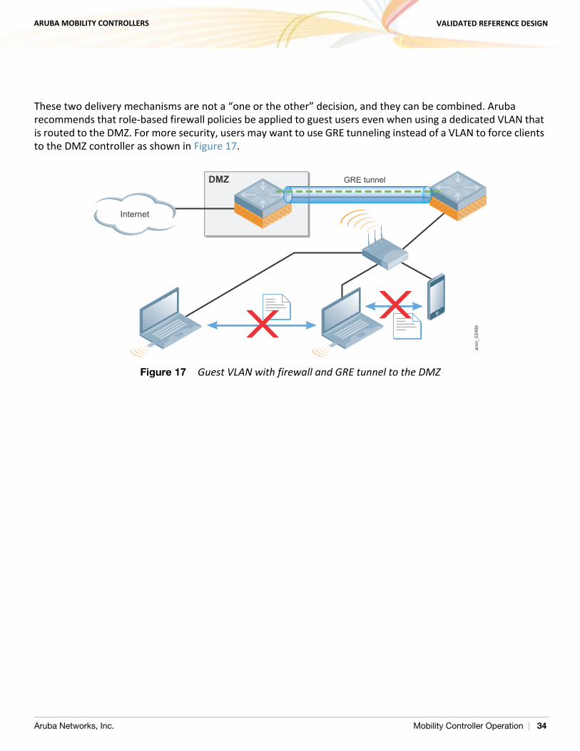
These two delivery mechanisms are not a “one or the other” decision, and they can be combined. Aruba recommends that role-based firewall policies be applied to guest users even when using a dedicated VLAN that is routed to the DMZ. For more security, users may want to use GRE tunneling instead of a VLAN to force clients to the DMZ controller as shown in Figure 17.
Figure 17 Guest VLAN with firewall and GRE tunnel to the DMZ
arun
_024
6b
Internet
GRE tunnelDMZ
Aruba Networks, Inc. Mobility Controller Operation | 34
ARUBA MOBILITY CONTROLLERS VALIDATED REFERENCE DESIGN
Dedicated AP VLANs
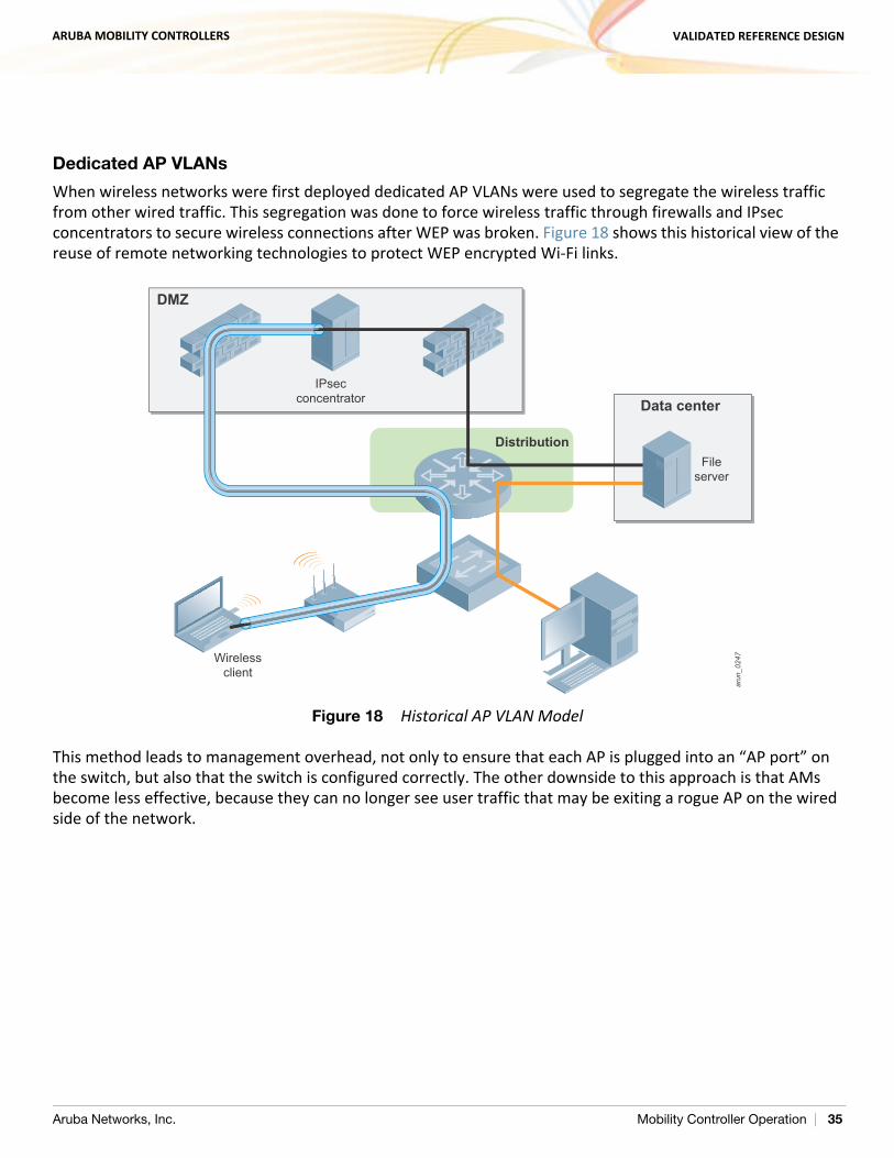
When wireless networks were first deployed dedicated AP VLANs were used to segregate the wireless traffic from other wired traffic. This segregation was done to force wireless traffic through firewalls and IPsec concentrators to secure wireless connections after WEP was broken. Figure 18 shows this historical view of the reuse of remote networking technologies to protect WEP encrypted Wi-Fi links.
Figure 18 Historical AP VLAN Model
This method leads to management overhead, not only to ensure that each AP is plugged into an “AP port” on the switch, but also that the switch is configured correctly. The other downside to this approach is that AMs become less effective, because they can no longer see user traffic that may be exiting a rogue AP on the wired side of the network.
arun
_024
7
Data center
DMZ
Distribution
IPsecconcentrator
Wirelessclient
Fileserver
Aruba Networks, Inc. Mobility Controller Operation | 35
ARUBA MOBILITY CONTROLLERS VALIDATED REFERENCE DESIGN
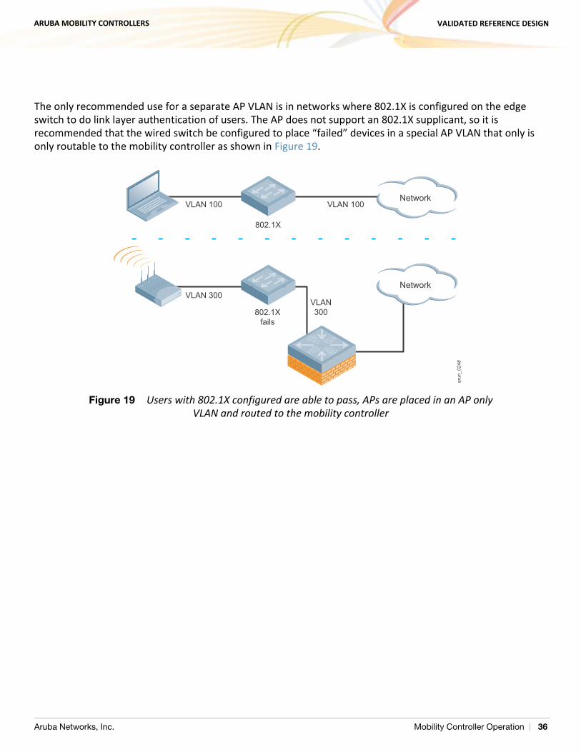
The only recommended use for a separate AP VLAN is in networks where 802.1X is configured on the edge switch to do link layer authentication of users. The AP does not support an 802.1X supplicant, so it is recommended that the wired switch be configured to place “failed” devices in a special AP VLAN that only is only routable to the mobility controller as shown in Figure 19.
Figure 19 Users with 802.1X configured are able to pass, APs are placed in an AP only VLAN and routed to the mobility controller
arun
_024
8
Network
Network
802.1X
VLAN 100VLAN 100
VLAN300
VLAN 300
802.1Xfails
Aruba Networks, Inc. Mobility Controller Operation | 36
ARUBA MOBILITY CONTROLLERS VALIDATED REFERENCE DESIGN
Quarantine VLANs
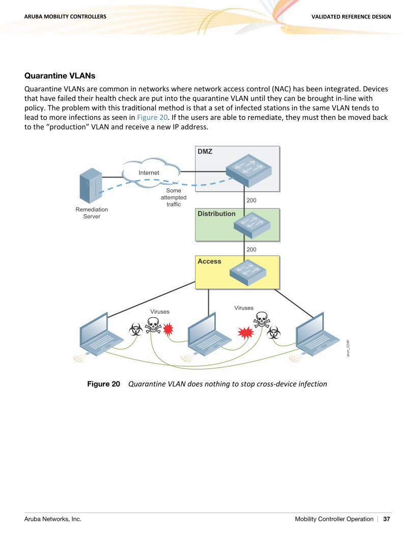
Quarantine VLANs are common in networks where network access control (NAC) has been integrated. Devices that have failed their health check are put into the quarantine VLAN until they can be brought in-line with policy. The problem with this traditional method is that a set of infected stations in the same VLAN tends to lead to more infections as seen in Figure 20. If the users are able to remediate, they must then be moved back to the “production” VLAN and receive a new IP address.
Figure 20 Quarantine VLAN does nothing to stop cross-device infection
arun
_024
9
200
Internet
200
DMZ
Distribution
Access
RemediationServer
Someattempted
traffic
Viruses Viruses
Aruba Networks, Inc. Mobility Controller Operation | 37
ARUBA MOBILITY CONTROLLERS VALIDATED REFERENCE DESIGN
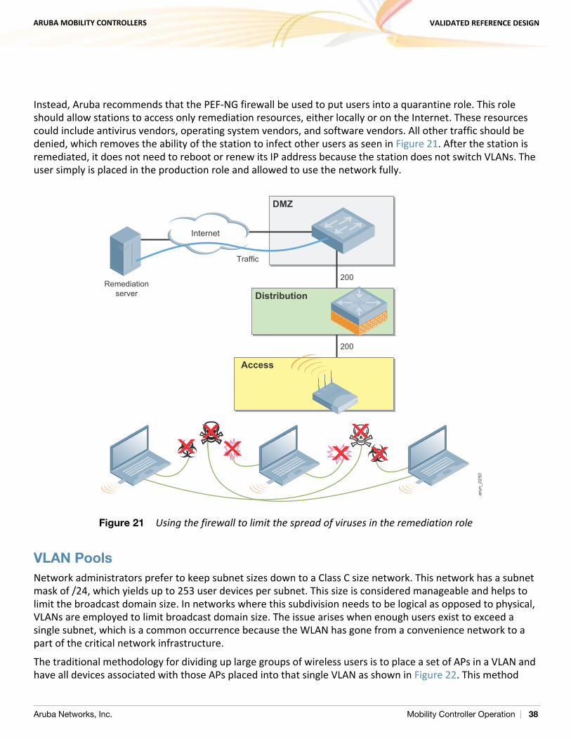
Instead, Aruba recommends that the PEF-NG firewall be used to put users into a quarantine role. This role should allow stations to access only remediation resources, either locally or on the Internet. These resources could include antivirus vendors, operating system vendors, and software vendors. All other traffic should be denied, which removes the ability of the station to infect other users as seen in Figure 21. After the station is remediated, it does not need to reboot or renew its IP address because the station does not switch VLANs. The user simply is placed in the production role and allowed to use the network fully.
Figure 21 Using the firewall to limit the spread of viruses in the remediation role
VLAN PoolsNetwork administrators prefer to keep subnet sizes down to a Class C size network. This network has a subnet mask of /24, which yields up to 253 user devices per subnet. This size is considered manageable and helps to limit the broadcast domain size. In networks where this subdivision needs to be logical as opposed to physical, VLANs are employed to limit broadcast domain size. The issue arises when enough users exist to exceed a single subnet, which is a common occurrence because the WLAN has gone from a convenience network to a part of the critical network infrastructure.
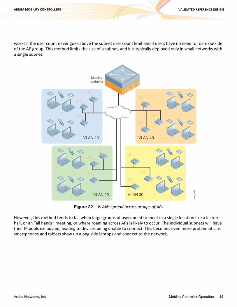
The traditional methodology for dividing up large groups of wireless users is to place a set of APs in a VLAN and have all devices associated with those APs placed into that single VLAN as shown in Figure 22. This method
arun
_025
0
200
Internet
200
DMZ
Distribution
Access
Remediationserver
Traffic
Aruba Networks, Inc. Mobility Controller Operation | 38
ARUBA MOBILITY CONTROLLERS VALIDATED REFERENCE DESIGN
works if the user count never goes above the subnet user count limit and if users have no need to roam outside of the AP group. This method limits the size of a subnet, and it is typically deployed only in small networks with a single subnet.
Figure 22 VLANs spread across groups of APs
However, this method tends to fail when large groups of users need to meet in a single location like a lecture hall, or an “all hands” meeting, or where roaming across APs is likely to occur. The individual subnets will have their IP pools exhausted, leading to devices being unable to connect. This becomes even more problematic as smartphones and tablets show up along side laptops and connect to the network.
arun_048ar
un_0
251
VLAN 10 VLAN 40
VLAN 30VLAN 20
Mobilitycontroller
Aruba Networks, Inc. Mobility Controller Operation | 39
ARUBA MOBILITY CONTROLLERS VALIDATED REFERENCE DESIGN
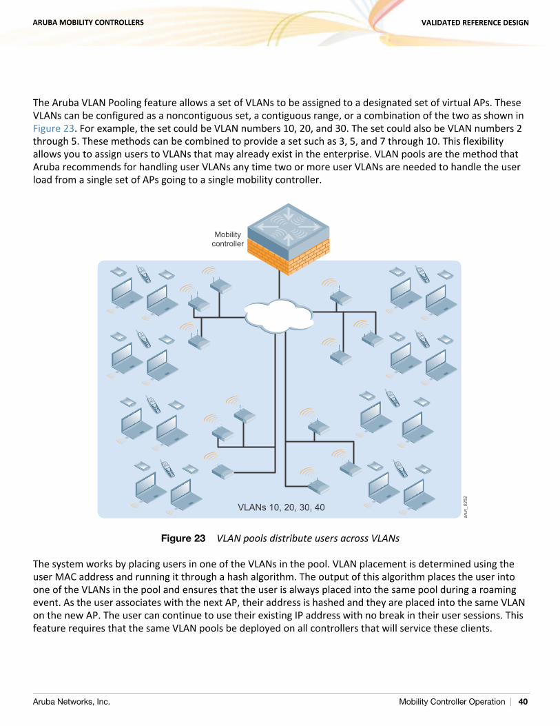
The Aruba VLAN Pooling feature allows a set of VLANs to be assigned to a designated set of virtual APs. These VLANs can be configured as a noncontiguous set, a contiguous range, or a combination of the two as shown in Figure 23. For example, the set could be VLAN numbers 10, 20, and 30. The set could also be VLAN numbers 2 through 5. These methods can be combined to provide a set such as 3, 5, and 7 through 10. This flexibility allows you to assign users to VLANs that may already exist in the enterprise. VLAN pools are the method that Aruba recommends for handling user VLANs any time two or more user VLANs are needed to handle the user load from a single set of APs going to a single mobility controller.
Figure 23 VLAN pools distribute users across VLANs
The system works by placing users in one of the VLANs in the pool. VLAN placement is determined using the user MAC address and running it through a hash algorithm. The output of this algorithm places the user into one of the VLANs in the pool and ensures that the user is always placed into the same pool during a roaming event. As the user associates with the next AP, their address is hashed and they are placed into the same VLAN on the new AP. The user can continue to use their existing IP address with no break in their user sessions. This feature requires that the same VLAN pools be deployed on all controllers that will service these clients.
arun_049
arun
_025
2
VLANs 10, 20, 30, 40
Mobilitycontroller
Aruba Networks, Inc. Mobility Controller Operation | 40
ARUBA MOBILITY CONTROLLERS VALIDATED REFERENCE DESIGN
Packet SizingWherever possible the network should be configured to support jumbo frames to avoid fragmentation of the packets. When this configuration is not possible due to lack of hardware support, the maximum MTU should be configured on all devices. This setting is especially important for video transmissions, because the loss of key video frames can cause the entire packet to be retransmitted. It is also important that transmitters are aware of the frame size limitations. For instance, video servers should be configured to use the maximum MTU of the network to limit their packet size to the network-supported maximum and avoid fragmentation.
Default Gateways and RoutesUsers terminate on the Aruba Mobility Controller, so there can be some debate about where the default gateway should exist and how routing table updates should occur. This section describes the options for deploying the mobility controller as the default Layer 3 gateway as opposed to a Layer 2 device. Also discussed is how user subnets should be routed if the controller is selected as the gateway.
Layer 2 Deployments
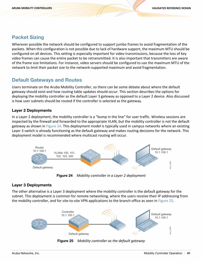
In a Layer 2 deployment, the mobility controller is a “bump in the line” for user traffic. Wireless sessions are inspected by the firewall and forwarded to the appropriate VLAN, but the mobility controller is not the default gateway as shown in Figure 24. This deployment model is typically used in campus networks where an existing Layer 3 switch is already functioning as the default gateway and makes routing decisions for the network. This deployment model is recommended where multicast routing will occur.
Figure 24 Mobility controller in a Layer 2 deployment
Layer 3 Deployments
The other alternative is a Layer 3 deployment where the mobility controller is the default gateway for the subnet. This deployment is common for remote networking, where the users receive their IP addressing from the mobility controller, and for site-to-site VPN applications to the branch office as seen in Figure 25.
Figure 25 Mobility controller as the default gateway
arun
_025
3Default gateway
Default gateway10.1.100.1VLANs 100, 101,
102, 103, 200
Router10.1.100.1
arun
_025
4
Default gateway
Default gateway10.1.100.1
Controller10.1.100.1
Aruba Networks, Inc. Mobility Controller Operation | 41
ARUBA MOBILITY CONTROLLERS VALIDATED REFERENCE DESIGN
When a RAP is deployed, all addressing is delivered from the mobility controller to the client machines. Machines on the same site may receive different addresses from different pools, which would make routing difficult for a traditional routed network to manage. The mobility controller is the one vending the addressing, so it is logical for it to also act as the default gateway for those subnets.
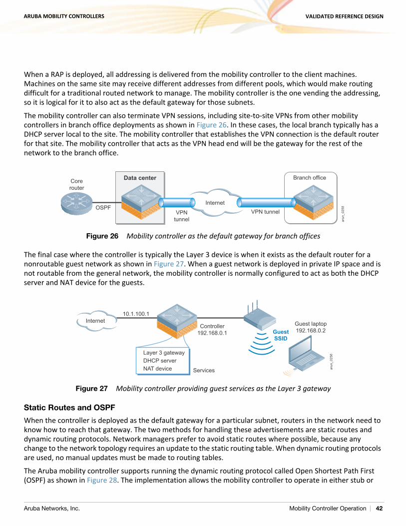
The mobility controller can also terminate VPN sessions, including site-to-site VPNs from other mobility controllers in branch office deployments as shown in Figure 26. In these cases, the local branch typically has a DHCP server local to the site. The mobility controller that establishes the VPN connection is the default router for that site. The mobility controller that acts as the VPN head end will be the gateway for the rest of the network to the branch office.
Figure 26 Mobility controller as the default gateway for branch offices
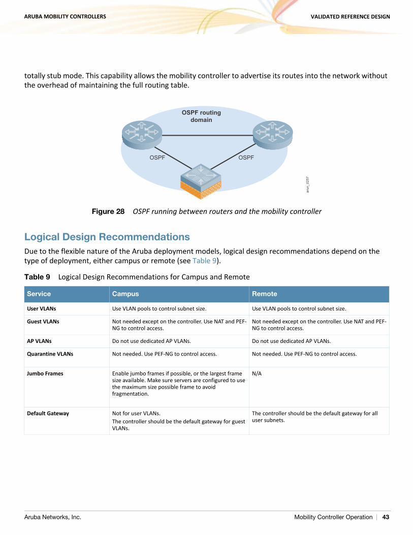
The final case where the controller is typically the Layer 3 device is when it exists as the default router for a nonroutable guest network as shown in Figure 27. When a guest network is deployed in private IP space and is not routable from the general network, the mobility controller is normally configured to act as both the DHCP server and NAT device for the guests.
Figure 27 Mobility controller providing guest services as the Layer 3 gateway
Static Routes and OSPF
When the controller is deployed as the default gateway for a particular subnet, routers in the network need to know how to reach that gateway. The two methods for handling these advertisements are static routes and dynamic routing protocols. Network managers prefer to avoid static routes where possible, because any change to the network topology requires an update to the static routing table. When dynamic routing protocols are used, no manual updates must be made to routing tables.
The Aruba mobility controller supports running the dynamic routing protocol called Open Shortest Path First (OSPF) as shown in Figure 28. The implementation allows the mobility controller to operate in either stub or
arun
_025
5
Data centerCorerouter
OSPFInternet
VPNtunnel
VPN tunnel
Branch office
arun
_025
6Layer 3 gatewayDHCP serverNAT device Services
10.1.100.1Internet Guest laptop
192.168.0.2Controller
192.168.0.1 GuestSSID
Aruba Networks, Inc. Mobility Controller Operation | 42
ARUBA MOBILITY CONTROLLERS VALIDATED REFERENCE DESIGN
totally stub mode. This capability allows the mobility controller to advertise its routes into the network without the overhead of maintaining the full routing table.
Figure 28 OSPF running between routers and the mobility controller
Logical Design Recommendations Due to the flexible nature of the Aruba deployment models, logical design recommendations depend on the type of deployment, either campus or remote (see Table 9).
Table 9 Logical Design Recommendations for Campus and Remote
Service Campus Remote
User VLANs Use VLAN pools to control subnet size. Use VLAN pools to control subnet size.
Guest VLANs Not needed except on the controller. Use NAT and PEF-NG to control access.
Not needed except on the controller. Use NAT and PEF-NG to control access.
AP VLANs Do not use dedicated AP VLANs. Do not use dedicated AP VLANs.
Quarantine VLANs Not needed. Use PEF-NG to control access. Not needed. Use PEF-NG to control access.
Jumbo Frames Enable jumbo frames if possible, or the largest frame size available. Make sure servers are configured to use the maximum size possible frame to avoid fragmentation.
N/A
Default Gateway Not for user VLANs.The controller should be the default gateway for guest VLANs.
The controller should be the default gateway for all user subnets.
arun
_025
7
OSPF
OSPF routingdomain
OSPF
Aruba Networks, Inc. Mobility Controller Operation | 43

ARUBA MOBILITY CONTROLLERS VALIDATED REFERENCE DESIGN
Campus Logical Design Recommendations
User VLANs: If more than one user VLAN is required, Aruba recommends that VLAN pools be used to distribute users more evenly across the pools. By using multiple VLANs in a VLAN pool, the size of broadcast domains are reduced and the configuration is simplified for the network manager. Aruba recommends the use of class C (/24) subnets, and the subnets across all VLANs in a pool should be the same size.
Guest VLANs: Though guest VLANs are common in many deployments for historical reasons, guest VLANs that cross the internal network to the DMZ are not needed in the Aruba system. Aruba recommends that organizations consider deploying guests on a nonroutable network with a VLAN that exists only on the Aruba Mobility Controller. Consider having the mobility controller act as the DHCP and NAT server for this self-contained VLAN. The guest role should be locked down so that guest users have limited or preferably no access to internal resources and only limited access to Internet protocols.
AP VLANs: Aruba strongly recommends that edge access VLANs should not be dedicated to APs except in environments where 802.1X is a requirement on the wired edge. The APs should use the existing edge VLANs as long as they have the ability to reach the mobility controller. Deploying the APs in the existing VLANs allows for the full use of the Aruba rogue detection capabilities. If 802.1X is in use on the wired edge, Aruba recommends placing APs in a VLAN that is routable only to the interface of the mobility controller.The other exception to this rule is for AMs. The AMs can be connected to a trunk port that contains all VLANs that appear on any wired access port within range of the AM. This connection is used for the AM to do wireless-to-wired correlation when it is tracking rogue APs. Alternatively, all access VLANs can be trunked to the mobility controller and wired correlation can be performed at that point.
Quarantine VLANs: Aruba also recommends against the use of a quarantine VLAN unless it is required by security policy. Instead, Aruba recommends that the integrated firewall and user roles are used to lock down users with a quarantine role. The locations and communications capabilities of the quarantined device are limited more effectively with a quarantine role than with a shared VLAN.
Default router: In most campus environments, the Aruba Mobility Controller is deployed as a Layer 2 device to provide mobile access and security policy, but not to act as the default gateway for the user subnets. The default gateways typically already exist and are already set in DHCP scopes. To continue to use these devices provides the least disruption to the existing network. Aruba does recommend that the mobility controller act as default gateway and DHCP server for guest VLANs in all deployments where the VLAN exists only on the mobility controller and for user VLANs in remote access deployments. In these deployments, the mobility controller is the only networking device with clear visibility into the user subnets, and as such should be deployed as the default gateway.
Aruba Networks, Inc. Mobility Controller Operation | 44
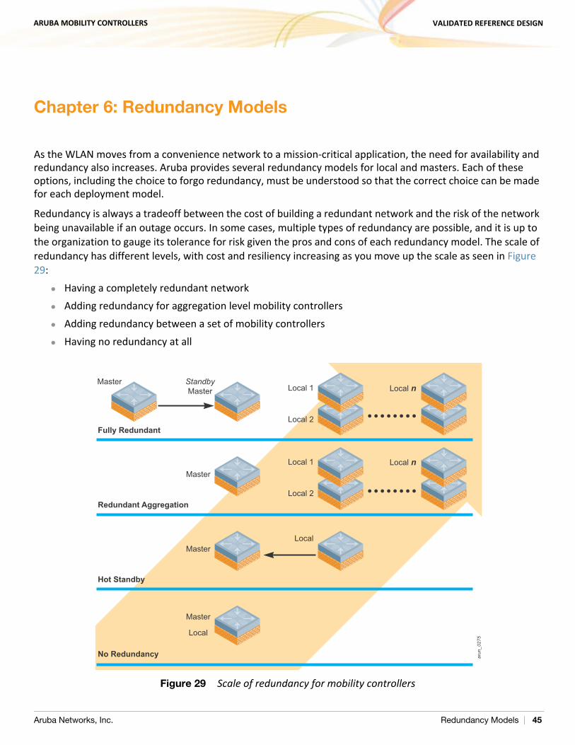
ARUBA MOBILITY CONTROLLERS VALIDATED REFERENCE DESIGN
Chapter 6: Redundancy Models
As the WLAN moves from a convenience network to a mission-critical application, the need for availability and redundancy also increases. Aruba provides several redundancy models for local and masters. Each of these options, including the choice to forgo redundancy, must be understood so that the correct choice can be made for each deployment model.
Redundancy is always a tradeoff between the cost of building a redundant network and the risk of the network being unavailable if an outage occurs. In some cases, multiple types of redundancy are possible, and it is up to the organization to gauge its tolerance for risk given the pros and cons of each redundancy model. The scale of redundancy has different levels, with cost and resiliency increasing as you move up the scale as seen in Figure 29:
Having a completely redundant network Adding redundancy for aggregation level mobility controllers Adding redundancy between a set of mobility controllers Having no redundancy at all
Figure 29 Scale of redundancy for mobility controllers
arun
_027
5
Master StandbyMaster Local 1
Fully Redundant
Local n
MasterLocal 1
Local 2
Local 2Redundant Aggregation
Local n
MasterLocal
Hot Standby
Master
Local
No Redundancy
Aruba Networks, Inc. Redundancy Models | 45
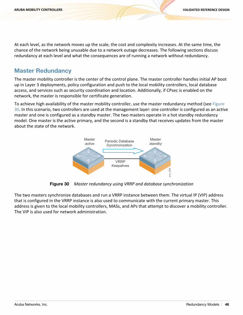
ARUBA MOBILITY CONTROLLERS VALIDATED REFERENCE DESIGN
At each level, as the network moves up the scale, the cost and complexity increases. At the same time, the chance of the network being unusable due to a network outage decreases. The following sections discuss redundancy at each level and what the consequences are of running a network without redundancy.
Master RedundancyThe master mobility controller is the center of the control plane. The master controller handles initial AP boot up in Layer 3 deployments, policy configuration and push to the local mobility controllers, local database access, and services such as security coordination and location. Additionally, if CPsec is enabled on the network, the master is responsible for certificate generation.
To achieve high availability of the master mobility controller, use the master redundancy method (see Figure 30. In this scenario, two controllers are used at the management layer: one controller is configured as an active master and one is configured as a standby master. The two masters operate in a hot standby redundancy model. One master is the active primary, and the second is a standby that receives updates from the master about the state of the network.
Figure 30 Master redundancy using VRRP and database synchronization
The two masters synchronize databases and run a VRRP instance between them. The virtual IP (VIP) address that is configured in the VRRP instance is also used to communicate with the current primary master. This address is given to the local mobility controllers, MASs, and APs that attempt to discover a mobility controller. The VIP is also used for network administration.
RNSG_043
arun
_026
2
Masterstandby
VRRPKeepalives
Periodic DatabaseDynchronization
Masteractive
Aruba Networks, Inc. Redundancy Models | 46
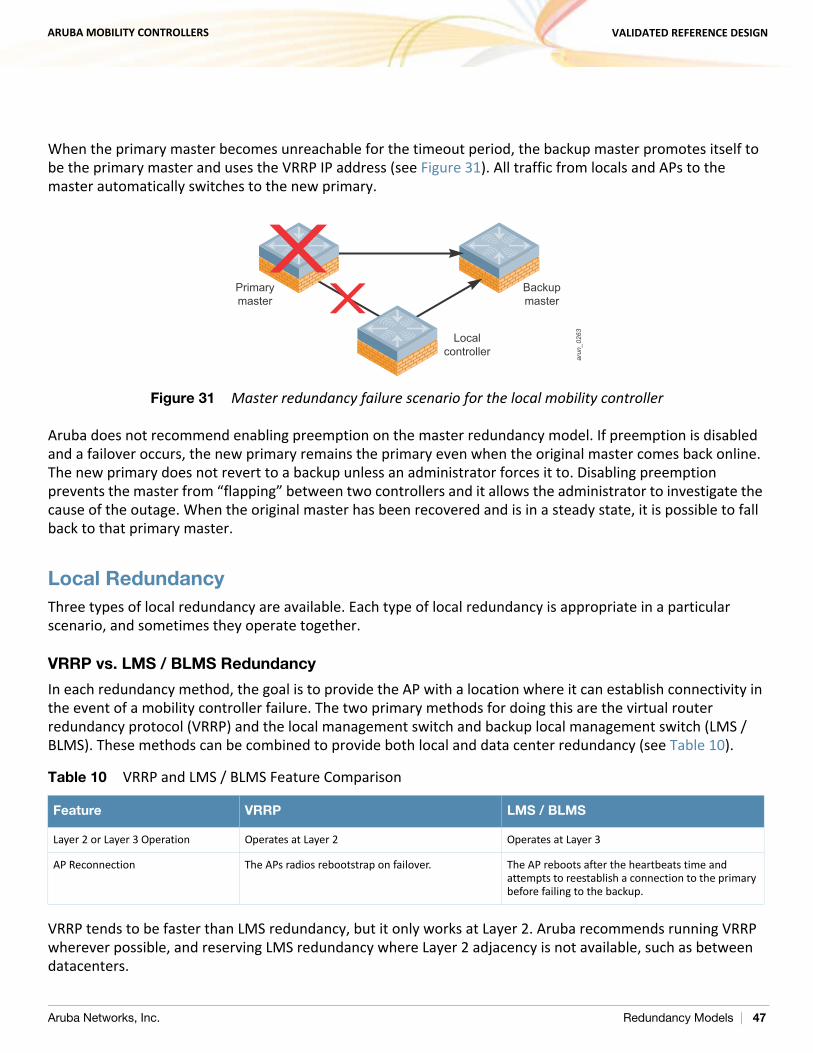
ARUBA MOBILITY CONTROLLERS VALIDATED REFERENCE DESIGN
When the primary master becomes unreachable for the timeout period, the backup master promotes itself to be the primary master and uses the VRRP IP address (see Figure 31). All traffic from locals and APs to the master automatically switches to the new primary.
Figure 31 Master redundancy failure scenario for the local mobility controller
Aruba does not recommend enabling preemption on the master redundancy model. If preemption is disabled and a failover occurs, the new primary remains the primary even when the original master comes back online. The new primary does not revert to a backup unless an administrator forces it to. Disabling preemption prevents the master from “flapping” between two controllers and it allows the administrator to investigate the cause of the outage. When the original master has been recovered and is in a steady state, it is possible to fall back to that primary master.
Local Redundancy Three types of local redundancy are available. Each type of local redundancy is appropriate in a particular scenario, and sometimes they operate together.
VRRP vs. LMS / BLMS Redundancy
In each redundancy method, the goal is to provide the AP with a location where it can establish connectivity in the event of a mobility controller failure. The two primary methods for doing this are the virtual router redundancy protocol (VRRP) and the local management switch and backup local management switch (LMS / BLMS). These methods can be combined to provide both local and data center redundancy (see Table 10).
VRRP tends to be faster than LMS redundancy, but it only works at Layer 2. Aruba recommends running VRRP wherever possible, and reserving LMS redundancy where Layer 2 adjacency is not available, such as between datacenters.
Table 10 VRRP and LMS / BLMS Feature Comparison
Feature VRRP LMS / BLMS
Layer 2 or Layer 3 Operation Operates at Layer 2 Operates at Layer 3
AP Reconnection The APs radios rebootstrap on failover. The AP reboots after the heartbeats time and attempts to reestablish a connection to the primary before failing to the backup.
arun
_026
3
Primarymaster
Localcontroller
Backupmaster
Aruba Networks, Inc. Redundancy Models | 47
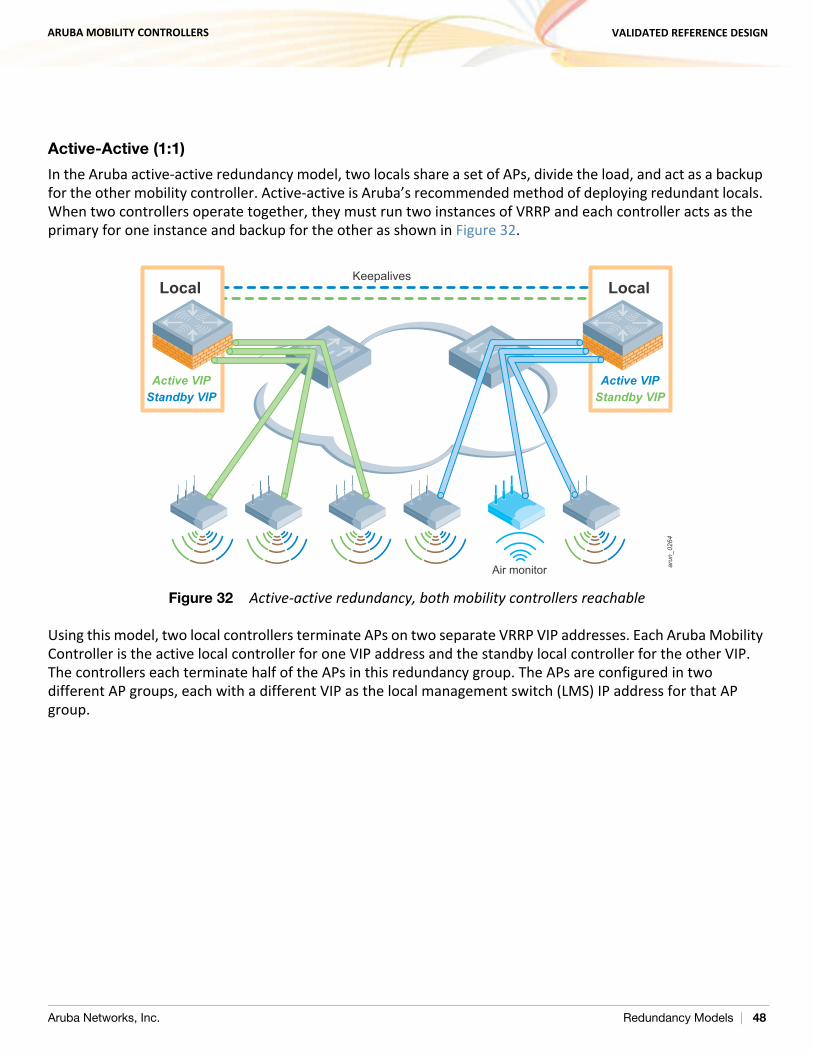
ARUBA MOBILITY CONTROLLERS VALIDATED REFERENCE DESIGN
Active-Active (1:1)
In the Aruba active-active redundancy model, two locals share a set of APs, divide the load, and act as a backup for the other mobility controller. Active-active is Aruba’s recommended method of deploying redundant locals. When two controllers operate together, they must run two instances of VRRP and each controller acts as the primary for one instance and backup for the other as shown in Figure 32.
Figure 32 Active-active redundancy, both mobility controllers reachable
Using this model, two local controllers terminate APs on two separate VRRP VIP addresses. Each Aruba Mobility Controller is the active local controller for one VIP address and the standby local controller for the other VIP. The controllers each terminate half of the APs in this redundancy group. The APs are configured in two different AP groups, each with a different VIP as the local management switch (LMS) IP address for that AP group.
arun_044
arun
_026
4
Air monitor
Keepalives
Active VIPStandby VIP
Local
Active VIPStandby VIP
Local
Aruba Networks, Inc. Redundancy Models | 48
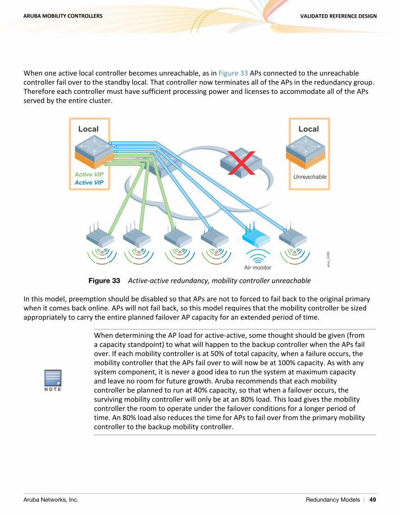
ARUBA MOBILITY CONTROLLERS VALIDATED REFERENCE DESIGN
When one active local controller becomes unreachable, as in Figure 33 APs connected to the unreachable controller fail over to the standby local. That controller now terminates all of the APs in the redundancy group. Therefore each controller must have sufficient processing power and licenses to accommodate all of the APs served by the entire cluster.
Figure 33 Active-active redundancy, mobility controller unreachable
In this model, preemption should be disabled so that APs are not to forced to fail back to the original primary when it comes back online. APs will not fail back, so this model requires that the mobility controller be sized appropriately to carry the entire planned failover AP capacity for an extended period of time.
N O T E
When determining the AP load for active-active, some thought should be given (from a capacity standpoint) to what will happen to the backup controller when the APs fail over. If each mobility controller is at 50% of total capacity, when a failure occurs, the mobility controller that the APs fail over to will now be at 100% capacity. As with any system component, it is never a good idea to run the system at maximum capacity and leave no room for future growth. Aruba recommends that each mobility controller be planned to run at 40% capacity, so that when a failover occurs, the surviving mobility controller will only be at an 80% load. This load gives the mobility controller the room to operate under the failover conditions for a longer period of time. An 80% load also reduces the time for APs to fail over from the primary mobility controller to the backup mobility controller.
arun_045
arun
_026
5
Air monitor
Local
Active VIPActive VIP
Local
Unreachable
Aruba Networks, Inc. Redundancy Models | 49
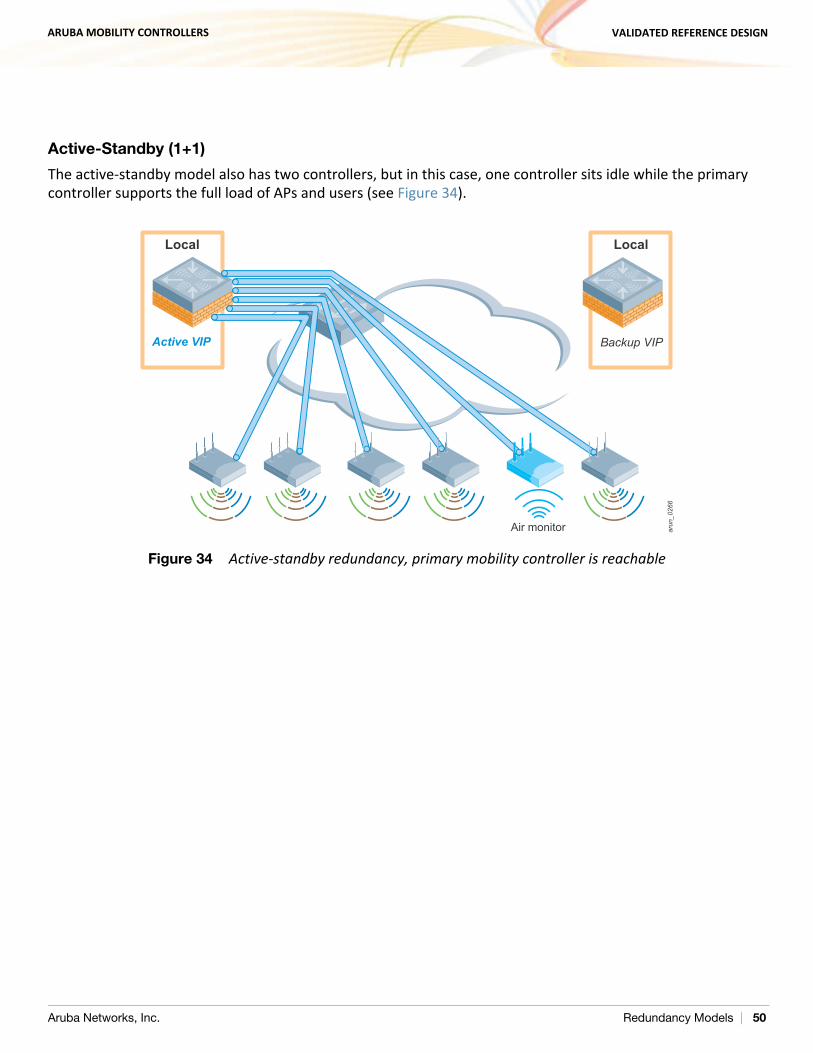
ARUBA MOBILITY CONTROLLERS VALIDATED REFERENCE DESIGN
Active-Standby (1+1)
The active-standby model also has two controllers, but in this case, one controller sits idle while the primary controller supports the full load of APs and users (see Figure 34).
Figure 34 Active-standby redundancy, primary mobility controller is reachable
arun
_026
6
Air monitor
Local
Active VIP
Local
Backup VIP
Aruba Networks, Inc. Redundancy Models | 50
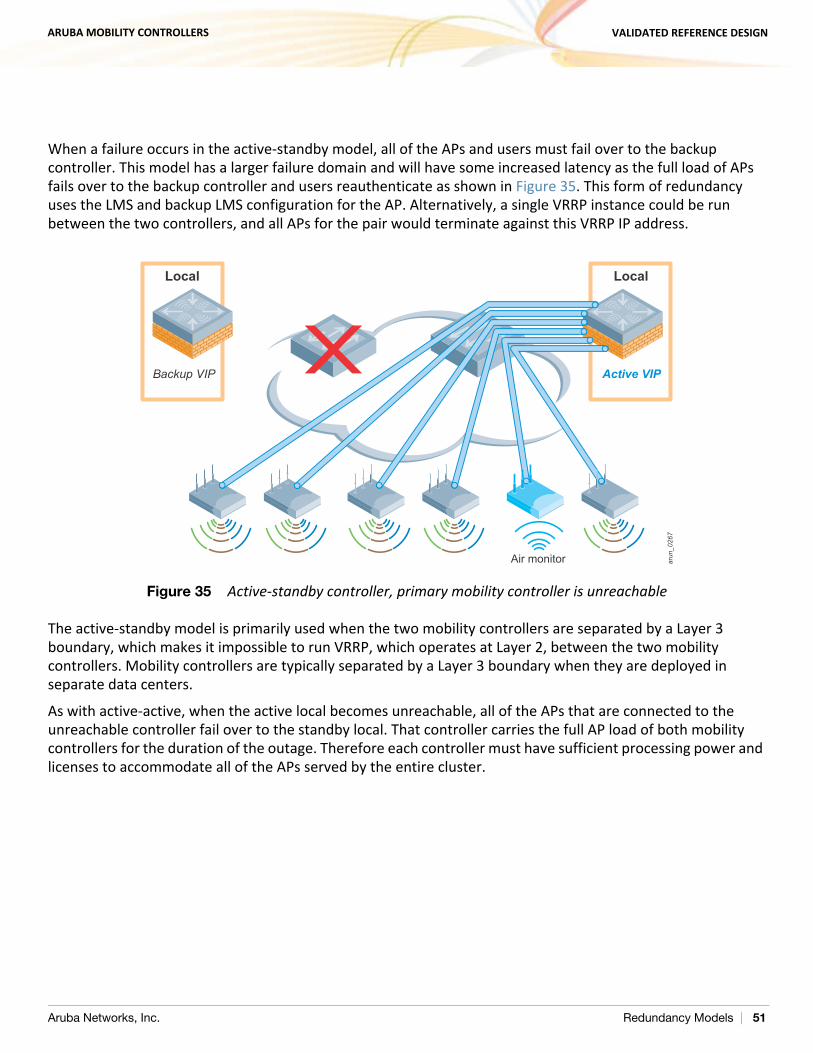
ARUBA MOBILITY CONTROLLERS VALIDATED REFERENCE DESIGN
When a failure occurs in the active-standby model, all of the APs and users must fail over to the backup controller. This model has a larger failure domain and will have some increased latency as the full load of APs fails over to the backup controller and users reauthenticate as shown in Figure 35. This form of redundancy uses the LMS and backup LMS configuration for the AP. Alternatively, a single VRRP instance could be run between the two controllers, and all APs for the pair would terminate against this VRRP IP address.
Figure 35 Active-standby controller, primary mobility controller is unreachable
The active-standby model is primarily used when the two mobility controllers are separated by a Layer 3 boundary, which makes it impossible to run VRRP, which operates at Layer 2, between the two mobility controllers. Mobility controllers are typically separated by a Layer 3 boundary when they are deployed in separate data centers.
As with active-active, when the active local becomes unreachable, all of the APs that are connected to the unreachable controller fail over to the standby local. That controller carries the full AP load of both mobility controllers for the duration of the outage. Therefore each controller must have sufficient processing power and licenses to accommodate all of the APs served by the entire cluster.
arun
_026
7
arun_045
Air monitor
LocalLocal
Active VIPBackup VIP
Aruba Networks, Inc. Redundancy Models | 51
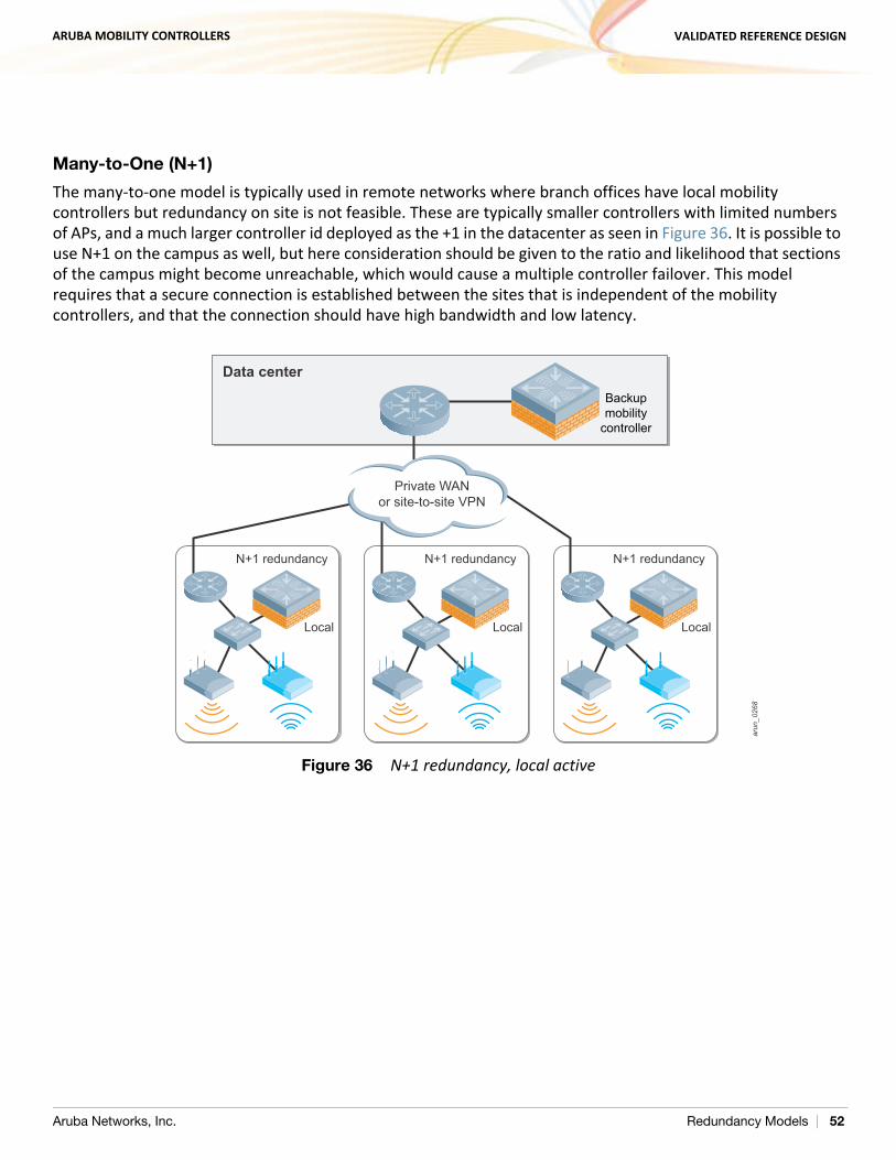
ARUBA MOBILITY CONTROLLERS VALIDATED REFERENCE DESIGN
Many-to-One (N+1)
The many-to-one model is typically used in remote networks where branch offices have local mobility controllers but redundancy on site is not feasible. These are typically smaller controllers with limited numbers of APs, and a much larger controller id deployed as the +1 in the datacenter as seen in Figure 36. It is possible to use N+1 on the campus as well, but here consideration should be given to the ratio and likelihood that sections of the campus might become unreachable, which would cause a multiple controller failover. This model requires that a secure connection is established between the sites that is independent of the mobility controllers, and that the connection should have high bandwidth and low latency.
Figure 36 N+1 redundancy, local activear
un_0
268
LocalLocal Local
Private WANor site-to-site VPN
N+1 redundancy N+1 redundancy N+1 redundancy
Data center
Backupmobility
controller
Aruba Networks, Inc. Redundancy Models | 52
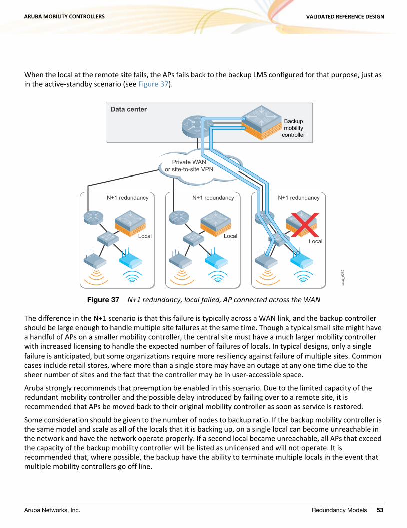
ARUBA MOBILITY CONTROLLERS VALIDATED REFERENCE DESIGN
When the local at the remote site fails, the APs fails back to the backup LMS configured for that purpose, just as in the active-standby scenario (see Figure 37).
Figure 37 N+1 redundancy, local failed, AP connected across the WAN
The difference in the N+1 scenario is that this failure is typically across a WAN link, and the backup controller should be large enough to handle multiple site failures at the same time. Though a typical small site might have a handful of APs on a smaller mobility controller, the central site must have a much larger mobility controller with increased licensing to handle the expected number of failures of locals. In typical designs, only a single failure is anticipated, but some organizations require more resiliency against failure of multiple sites. Common cases include retail stores, where more than a single store may have an outage at any one time due to the sheer number of sites and the fact that the controller may be in user-accessible space.
Aruba strongly recommends that preemption be enabled in this scenario. Due to the limited capacity of the redundant mobility controller and the possible delay introduced by failing over to a remote site, it is recommended that APs be moved back to their original mobility controller as soon as service is restored.
Some consideration should be given to the number of nodes to backup ratio. If the backup mobility controller is the same model and scale as all of the locals that it is backing up, on a single local can become unreachable in the network and have the network operate properly. If a second local became unreachable, all APs that exceed the capacity of the backup mobility controller will be listed as unlicensed and will not operate. It is recommended that, where possible, the backup have the ability to terminate multiple locals in the event that multiple mobility controllers go off line.
arun
_026
9
LocalLocalLocal
Data center
Backupmobility
controller
Private WANor site-to-site VPN
N+1 redundancyN+1 redundancy N+1 redundancy
Aruba Networks, Inc. Redundancy Models | 53
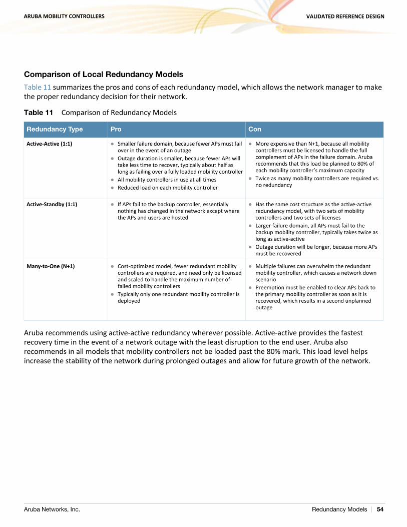
ARUBA MOBILITY CONTROLLERS VALIDATED REFERENCE DESIGN
Comparison of Local Redundancy Models
Table 11 summarizes the pros and cons of each redundancy model, which allows the network manager to make the proper redundancy decision for their network.
Aruba recommends using active-active redundancy wherever possible. Active-active provides the fastest recovery time in the event of a network outage with the least disruption to the end user. Aruba also recommends in all models that mobility controllers not be loaded past the 80% mark. This load level helps increase the stability of the network during prolonged outages and allow for future growth of the network.
Table 11 Comparison of Redundancy Models
Redundancy Type Pro Con
Active-Active (1:1) Smaller failure domain, because fewer APs must fail over in the event of an outage
Outage duration is smaller, because fewer APs will take less time to recover, typically about half as long as failing over a fully loaded mobility controller
All mobility controllers in use at all times Reduced load on each mobility controller
More expensive than N+1, because all mobility controllers must be licensed to handle the full complement of APs in the failure domain. Aruba recommends that this load be planned to 80% of each mobility controller’s maximum capacity
Twice as many mobility controllers are required vs. no redundancy
Active-Standby (1:1) If APs fail to the backup controller, essentially nothing has changed in the network except where the APs and users are hosted
Has the same cost structure as the active-active redundancy model, with two sets of mobility controllers and two sets of licenses
Larger failure domain, all APs must fail to the backup mobility controller, typically takes twice as long as active-active
Outage duration will be longer, because more APs must be recovered
Many-to-One (N+1) Cost-optimized model, fewer redundant mobility controllers are required, and need only be licensed and scaled to handle the maximum number of failed mobility controllers
Typically only one redundant mobility controller is deployed
Multiple failures can overwhelm the redundant mobility controller, which causes a network down scenario
Preemption must be enabled to clear APs back to the primary mobility controller as soon as it is recovered, which results in a second unplanned outage
Aruba Networks, Inc. Redundancy Models | 54
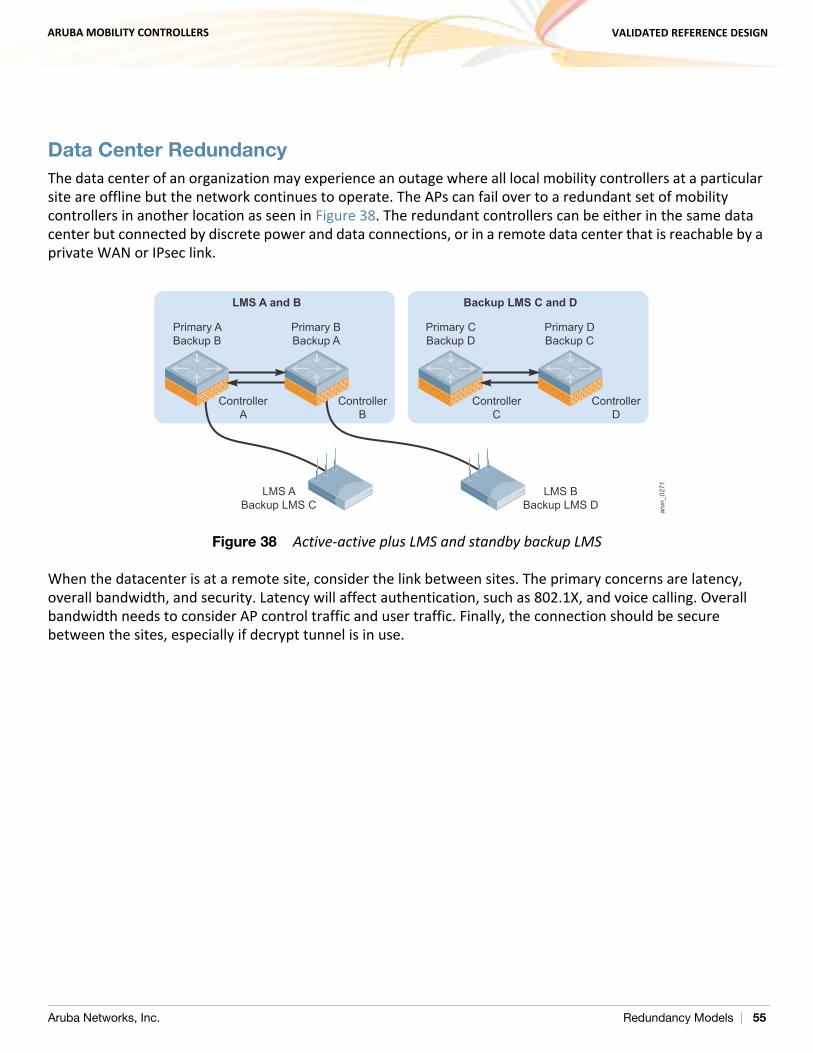
ARUBA MOBILITY CONTROLLERS VALIDATED REFERENCE DESIGN
Data Center RedundancyThe data center of an organization may experience an outage where all local mobility controllers at a particular site are offline but the network continues to operate. The APs can fail over to a redundant set of mobility controllers in another location as seen in Figure 38. The redundant controllers can be either in the same data center but connected by discrete power and data connections, or in a remote data center that is reachable by a private WAN or IPsec link.
Figure 38 Active-active plus LMS and standby backup LMS
When the datacenter is at a remote site, consider the link between sites. The primary concerns are latency, overall bandwidth, and security. Latency will affect authentication, such as 802.1X, and voice calling. Overall bandwidth needs to consider AP control traffic and user traffic. Finally, the connection should be secure between the sites, especially if decrypt tunnel is in use.
arun
_027
1
Primary ABackup B
ControllerA
ControllerB
LMS ABackup LMS C
LMS BBackup LMS D
LMS A and B
Primary BBackup A
Primary CBackup D
ControllerC
ControllerD
Backup LMS C and D
Primary DBackup C
Aruba Networks, Inc. Redundancy Models | 55
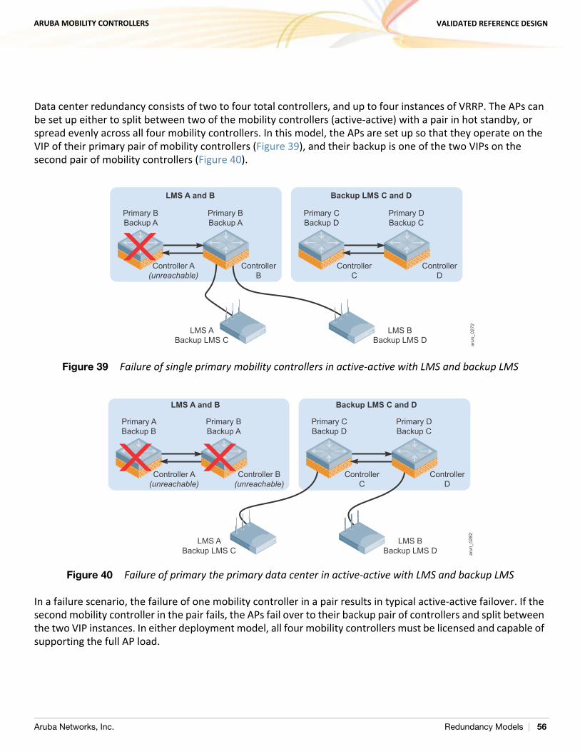
ARUBA MOBILITY CONTROLLERS VALIDATED REFERENCE DESIGN
Data center redundancy consists of two to four total controllers, and up to four instances of VRRP. The APs can be set up either to split between two of the mobility controllers (active-active) with a pair in hot standby, or spread evenly across all four mobility controllers. In this model, the APs are set up so that they operate on the VIP of their primary pair of mobility controllers (Figure 39), and their backup is one of the two VIPs on the second pair of mobility controllers (Figure 40).
Figure 39 Failure of single primary mobility controllers in active-active with LMS and backup LMS
Figure 40 Failure of primary the primary data center in active-active with LMS and backup LMS
In a failure scenario, the failure of one mobility controller in a pair results in typical active-active failover. If the second mobility controller in the pair fails, the APs fail over to their backup pair of controllers and split between the two VIP instances. In either deployment model, all four mobility controllers must be licensed and capable of supporting the full AP load.
arun
_027
2
Primary BBackup A
Controller A(unreachable)
ControllerB
LMS ABackup LMS C
LMS BBackup LMS D
LMS A and B
Primary BBackup A
Primary CBackup D
ControllerC
ControllerD
Backup LMS C and D
Primary DBackup C
arun
_028
2
Primary ABackup B
Controller A(unreachable)
Controller B(unreachable)
Primary BBackup A
Primary CBackup D
ControllerC
ControllerD
Primary DBackup C
LMS ABackup LMS C
LMS BBackup LMS D
LMS A and B Backup LMS C and D
Aruba Networks, Inc. Redundancy Models | 56
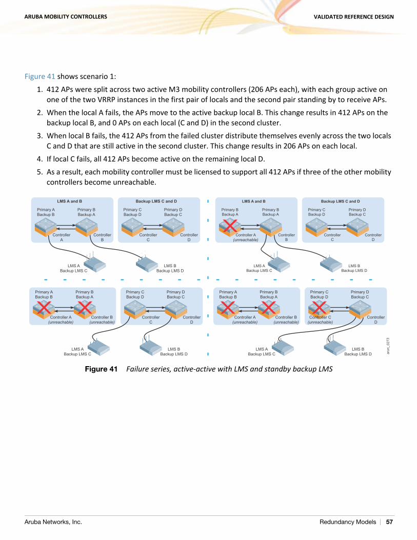
ARUBA MOBILITY CONTROLLERS VALIDATED REFERENCE DESIGN
Figure 41 shows scenario 1:1. 412 APs were split across two active M3 mobility controllers (206 APs each), with each group active on
one of the two VRRP instances in the first pair of locals and the second pair standing by to receive APs.2. When the local A fails, the APs move to the active backup local B. This change results in 412 APs on the
backup local B, and 0 APs on each local (C and D) in the second cluster.3. When local B fails, the 412 APs from the failed cluster distribute themselves evenly across the two locals
C and D that are still active in the second cluster. This change results in 206 APs on each local.4. If local C fails, all 412 APs become active on the remaining local D.5. As a result, each mobility controller must be licensed to support all 412 APs if three of the other mobility
controllers become unreachable.
Figure 41 Failure series, active-active with LMS and standby backup LMS
arun
_027
3
Primary ABackup B
Controller A(unreachable)
Controller B(unreachable)
Primary BBackup A
Primary CBackup D
ControllerC
ControllerD
Primary DBackup C
Primary ABackup B
Controller A(unreachable)
Controller B(unreachable)
Controller C(unreachable)
Primary BBackup A
Primary CBackup D
ControllerD
Primary DBackup C
Primary ABackup B
ControllerA
ControllerB
LMS ABackup LMS C
LMS BBackup LMS D
LMS A and B
Primary BBackup A
Primary CBackup D
ControllerC
ControllerD
Backup LMS C and D
Primary DBackup C
Primary BBackup A
Controller A(unreachable)
ControllerB
LMS ABackup LMS C
LMS BBackup LMS D
LMS A and B
Primary BBackup A
Primary CBackup D
ControllerC
ControllerD
Backup LMS C and D
Primary DBackup C
LMS ABackup LMS C
LMS BBackup LMS D
LMS ABackup LMS C
LMS BBackup LMS D
Aruba Networks, Inc. Redundancy Models | 57
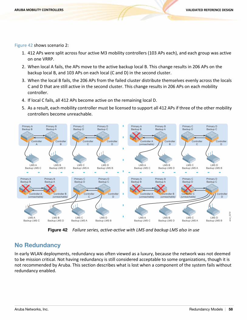
ARUBA MOBILITY CONTROLLERS VALIDATED REFERENCE DESIGN
Figure 42 shows scenario 2: 1. 412 APs were split across four active M3 mobility controllers (103 APs each), and each group was active
on one VRRP.2. When local A fails, the APs move to the active backup local B. This change results in 206 APs on the
backup local B, and 103 APs on each local (C and D) in the second cluster.3. When the local B fails, the 206 APs from the failed cluster distribute themselves evenly across the locals
C and D that are still active in the second cluster. This change results in 206 APs on each mobility controller.
4. If local C fails, all 412 APs become active on the remaining local D.5. As a result, each mobility controller must be licensed to support all 412 APs if three of the other mobility
controllers become unreachable.
Figure 42 Failure series, active-active with LMS and backup LMS also in use
No RedundancyIn early WLAN deployments, redundancy was often viewed as a luxury, because the network was not deemed to be mission critical. Not having redundancy is still considered acceptable to some organizations, though it is not recommended by Aruba. This section describes what is lost when a component of the system fails without redundancy enabled.
arun
_027
4
Primary ABackup B
ControllerA
ControllerB
LMS ABackup LMS C
LMS BBackup LMS D
LMS CBackup LMS A
LMS DBackup LMS B
Primary BBackup A
Primary CBackup D
ControllerC
ControllerD
Primary DBackup C
Primary ABackup B
Controller A(unreachable)
ControllerB
LMS ABackup LMS C
LMS BBackup LMS D
LMS CBackup LMS A
LMS DBackup LMS B
Primary BBackup A
Primary CBackup D
ControllerC
ControllerD
Primary DBackup C
Primary ABackup B
Controller A(unreachable)
Controller B(unreachable)
LMS ABackup LMS C
LMS BBackup LMS D
LMS CBackup LMS A
LMS DBackup LMS B
Primary BBackup A
Primary CBackup D
Controller C(unreachable)
ControllerD
Primary DBackup C
Primary ABackup B
Controller A(unreachable)
Controller B(unreachable)
LMS ABackup LMS C
LMS BBackup LMS D
LMS CBackup LMS A
LMS DBackup LMS B
Primary BBackup A
Primary CBackup D
ControllerC
ControllerD
Primary DBackup C
Aruba Networks, Inc. Redundancy Models | 58
ARUBA MOBILITY CONTROLLERS VALIDATED REFERENCE DESIGN
Master – No Redundancy
If the master fails without a backup, the following services stop working: AP boot: During the AP boot cycle, the AP must discover and connect to a provisioning mobility
controller. In almost all deployments this is the master mobility controller, because that mobility controller typically is not serving APs and is able to be a single source for AP provisioning. It is also far easier to configure either DNS lookup or a single DHCP option to find a single mobility controller than to manage multiple lookups or scopes. It is also possible to use Layer 2 discovery mechanisms to find a local mobility controller, but this is not realistic in larger deployments. If the master is unreachable, in certain cases the APs may not be able to reboot until the master is restored or their boot process is modified: In situations where DHCP option 43 is used, the APs are unable to boot until a new master is in place
or the DHCP scope option is modified to point at either a new master or to a local. If DNS is used to locate the master, the APs are down unless a second IP is also returned in the DNS
response that points to a local. Note that this configuration results in a protracted outage, and the local must have AP capacity to bring up and then redirect the APs as they fail to the backup DNS response. This outage is longer in duration, with each AP taking approximately 4-5 minutes to fail to the backup. Depending on the AP capacity on the backup, several attempts may be needed before the AP is able to connect and be properly redirected.
APs that rely on Aruba Discovery Protocol (ADP) continue to operate as long as a local is capable of answering their ADP request. These APs require Layer 2 connectivity to the local for ADP to function.
In all cases, APs that are currently operating continue to do so in the event that the master becomes unreachable until they are rebooted or power cycled.
Local policy configuration: Configuration, done either on the master or AirWave, requires that the master is operational to push configurations to the locals. If the master is not available, changes to the network policy configuration are not possible unless each mobility controller is modified manually, though local configuration at the IP level is possible.
Local database access is lost: If the master becomes unreachable, guest access using the local database, as well as when roaming between locals when machine authentication is enabled, is lost.
Monitoring, heat maps, and location: If AirWave is not present in the network, centralized network monitoring, heat map generation, and location services all are down.
Valid AP table: When the master is down, the valid AP table is no longer available for updates. The locals continue to function with cached data until that ages out. After that time, other APs in the network are seen as “unknown” instead of valid, interfering, or rogue. When this occurs, Adaptive Radio Management (ARM) increases power to the edge APs on both sides in an attempt to increase coverage and work around the now unknown AP. At AP border areas, overlapping channels and power lead to increased interference.
RFProtect coordination: When the master is down, RFProtect security loses its coordination capabilities between locals. Any new APs that show up are classified as “unknown,” which prevents automatic containment from functioning. Existing data remains until it ages out, and then all of the APs begin to be reclassified as “unknown.” If protection of valid stations is enabled, clients are prevented from joining
Aruba Networks, Inc. Redundancy Models | 59
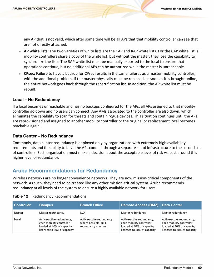
ARUBA MOBILITY CONTROLLERS VALIDATED REFERENCE DESIGN
any AP that is not valid, which after some time will be all APs that that mobility controller can see that are not directly attached.
AP white lists: The two varieties of white lists are the CAP and RAP white lists. For the CAP white list, all mobility controllers share a copy of the white list, but without the master, they lose the capability to synchronize the lists. The RAP white list must be manually exported to the local to ensure that operations continue, but no additional APs can be authorized while the master is unreachable.
CPsec: Failure to have a backup for CPsec results in the same failures as a master mobility controller, with the additional problem. If the master physically must be replaced, as soon as it is brought online, the entire network goes back through the recertification list. In addition, the AP white list must be rebuilt.
Local – No Redundancy
If a local becomes unreachable and has no backups configured for the APs, all APs assigned to that mobility controller go down and no users can connect. Any AMs associated to the controller are also down, which eliminates the capability to scan for threats and contain rogue devices. This situation continues until the APs are reprovisioned and assigned to another mobility controller or the original or replacement local becomes reachable again.
Data Center – No Redundancy
Commonly, data center redundancy is deployed only by organizations with extremely high availability requirements and the ability to have the APs connect through a separate set of infrastructure to the second set of controllers. Each organization must make a decision about the acceptable level of risk vs. cost around this higher level of redundancy.
Aruba Recommendations for RedundancyWireless networks are no longer convenience networks. They are now mission-critical components of the network. As such, they need to be treated like any other mission-critical system. Aruba recommends redundancy at all levels of the system to ensure a highly available network for users.
Table 12 Redundancy Recommendations
Controller Campus Branch Office Remote Access (DMZ) Data Center
Master Master redundancy N/A Master redundancy Master redundancy
Local Active-active redundancy, each mobility controller loaded at 40% of capacity, licensed to 80% of capacity
Active-active redundancy where possible, N+1 redundancy minimum
Active-active redundancy, each mobility controller loaded at 40% of capacity, licensed to 80% of capacity
Active-active redundancy, each mobility controller loaded at 40% of capacity, licensed to 80% of capacity
Aruba Networks, Inc. Redundancy Models | 60
ARUBA MOBILITY CONTROLLERS VALIDATED REFERENCE DESIGN
Chapter 7: Selecting the Proper Mobility Controller
The selection of the proper mobility controller depends greatly on the application and usage model for the network. This chapter examines the network usage considerations that must be considered, controller scaling, and selection criteria.
Information GatheringSelecting the proper mobility controller for the deployment depends on a number of factors, including forwarding mode, usage model, and AP count. Consider these factors to select the proper mobility controller for the application.
AP counts: The most common selection criteria for many organizations, the number of APs, often dictates a minimum controller scale. To determine the required AP count, a planning tool such as the Aruba VisualRF™ Plan or a traditional site survey determines the number of CAPs, AMs, and SMs necessary to provide adequate coverage. For remote access solutions, use the number of RAPs and/or the number of VIA agent or VPN users. Mixed environments require additional planning to ensure that the combined CAP and RAP counts do not exceed the maximum supported limits on the mobility controller.
MAS parameters: Consider two MAS parameters. The first is the number of switch devices. This is a 1:4 ratio, with each MAS equaling the supported capacity of four APs. The second parameter is the number of tunneled switch ports, with each port counting as one tunnel. This number counts against the maximum tunnel limits for the platform. VIA users: If the VIA agent will be deployed, the number of users must be known so that the deployment can be scaled appropriately. Additionally, the decision to make SSL fallback available for the VIA agents has an impact on the system and must be considered when selecting the appropriate mobility controller model and quantity.
Device count: Each platform has a maximum user count that limits the maximum devices that can associate with each controller. Look at the number of users that will use the WLAN at each site, and determine how many devices each user will have on average. Aruba recommends that each user count for two devices in general (laptop plus smartphone or tablet). Some organizations will have higher user to device ratios. Include employees, guests, contractors, and autonomous systems such as phones, printers, and building automation. Data throughput: As with any networking device, each mobility controller has a maximum platform throughput, which is also affected by encryption and firewall processing. Aruba recommends that baseline assessments of the data throughput of the organization be gathered to use in the mobility controller selection process. If a WLAN is already in place, use the AirWave management server before the Aruba WLAN is installed to help understand the average and peak throughput from wireless devices. If a WLAN is not currently in place, the network management system in place should be used to understand the size of traffic flows in the system.
Aruba Networks, Inc. Selecting the Proper Mobility Controller | 61
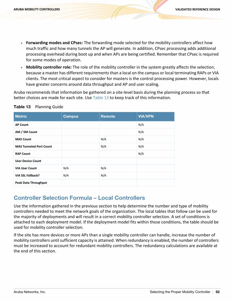
ARUBA MOBILITY CONTROLLERS VALIDATED REFERENCE DESIGN
Forwarding modes and CPsec: The forwarding mode selected for the mobility controllers affect how much traffic and how many tunnels the AP will generate. In addition, CPsec processing adds additional processing overhead during boot up and when APs are being certified. Remember that CPsec is required for some modes of operation.
Mobility controller role: The role of the mobility controller in the system greatly affects the selection, because a master has different requirements than a local on the campus or local terminating RAPs or VIA clients. The most critical aspect to consider for masters is the control processing power. However, locals have greater concerns around data throughput and AP and user scaling.
Aruba recommends that information be gathered on a site-level basis during the planning process so that better choices are made for each site. Use Table 13 to keep track of this information.
Controller Selection Formula – Local ControllersUse the information gathered in the previous section to help determine the number and type of mobility controllers needed to meet the network goals of the organization. The local tables that follow can be used for the majority of deployments and will result in a correct mobility controller selection. A set of conditions is attached to each deployment model. If the deployment model fits within those conditions, the table should be used for mobility controller selection.
If the site has more devices or more APs than a single mobility controller can handle, increase the number of mobility controllers until sufficient capacity is attained. When redundancy is enabled, the number of controllers must be increased to account for redundant mobility controllers. The redundancy calculations are available at the end of this section.
Table 13 Planning Guide
Metric Campus Remote VIA/VPN
AP Count N/A
AM / SM Count N/A
MAS Count N/A N/A
MAS Tunneled Port Count N/A N/A
RAP Count N/A
User Device Count
VIA User Count N/A N/A
VIA SSL Fallback? N/A N/A
Peak Data Throughput
Aruba Networks, Inc. Selecting the Proper Mobility Controller | 62
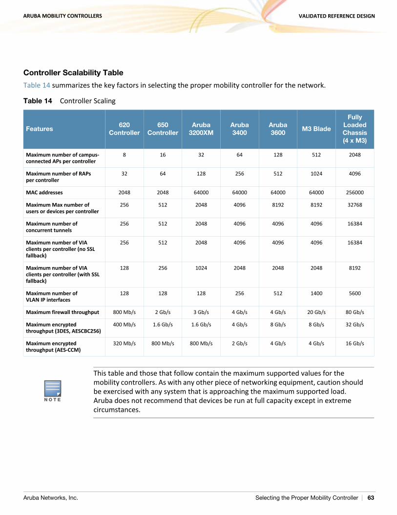
ARUBA MOBILITY CONTROLLERS VALIDATED REFERENCE DESIGN
Controller Scalability Table
Table 14 summarizes the key factors in selecting the proper mobility controller for the network.
Table 14 Controller Scaling
Features620
Controller650
ControllerAruba
3200XMAruba 3400
Aruba 3600
M3 Blade
Fully Loaded Chassis (4 x M3)
Maximum number of campus-connected APs per controller
8 16 32 64 128 512 2048
Maximum number of RAPs per controller
32 64 128 256 512 1024 4096
MAC addresses 2048 2048 64000 64000 64000 64000 256000
Maximum Max number of users or devices per controller
256 512 2048 4096 8192 8192 32768
Maximum number of concurrent tunnels
256 512 2048 4096 4096 4096 16384
Maximum number of VIA clients per controller (no SSL fallback)
256 512 2048 4096 4096 4096 16384
Maximum number of VIA clients per controller (with SSL fallback)
128 256 1024 2048 2048 2048 8192
Maximum number of VLAN IP interfaces
128 128 128 256 512 1400 5600
Maximum firewall throughput 800 Mb/s 2 Gb/s 3 Gb/s 4 Gb/s 4 Gb/s 20 Gb/s 80 Gb/s
Maximum encrypted throughput (3DES, AESCBC256)
400 Mb/s 1.6 Gb/s 1.6 Gb/s 4 Gb/s 8 Gb/s 8 Gb/s 32 Gb/s
Maximum encrypted throughput (AES-CCM)
320 Mb/s 800 Mb/s 800 Mb/s 2 Gb/s 4 Gb/s 4 Gb/s 16 Gb/s
N O T E
This table and those that follow contain the maximum supported values for the mobility controllers. As with any other piece of networking equipment, caution should be exercised with any system that is approaching the maximum supported load. Aruba does not recommend that devices be run at full capacity except in extreme circumstances.
Aruba Networks, Inc. Selecting the Proper Mobility Controller | 63
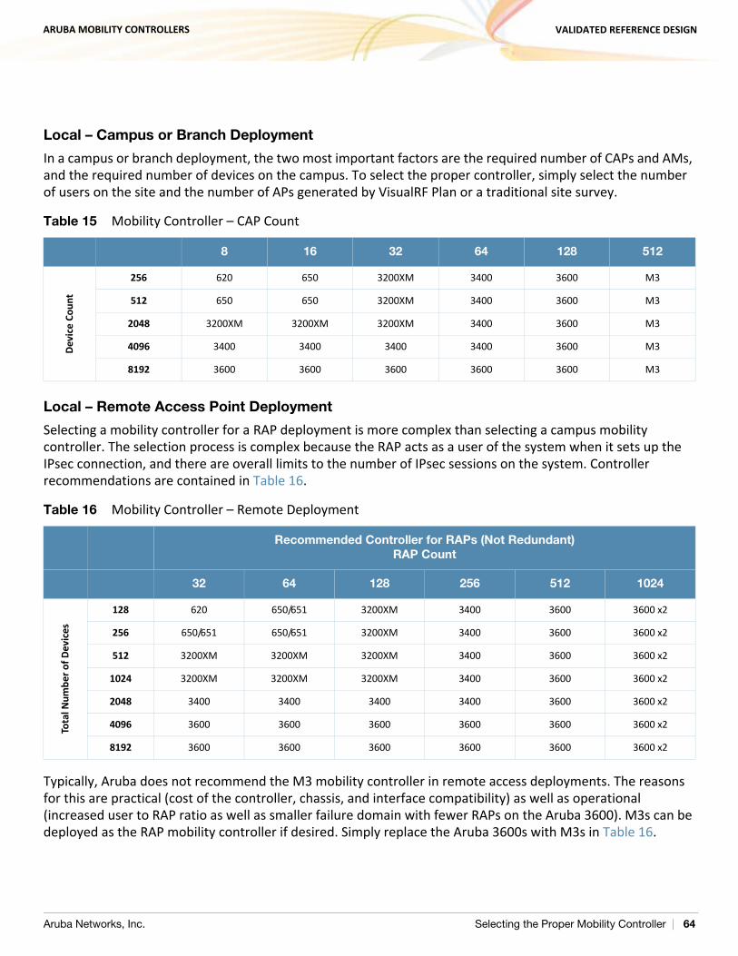
ARUBA MOBILITY CONTROLLERS VALIDATED REFERENCE DESIGN
Local – Campus or Branch Deployment
In a campus or branch deployment, the two most important factors are the required number of CAPs and AMs, and the required number of devices on the campus. To select the proper controller, simply select the number of users on the site and the number of APs generated by VisualRF Plan or a traditional site survey.
Local – Remote Access Point Deployment
Selecting a mobility controller for a RAP deployment is more complex than selecting a campus mobility controller. The selection process is complex because the RAP acts as a user of the system when it sets up the IPsec connection, and there are overall limits to the number of IPsec sessions on the system. Controller recommendations are contained in Table 16.
Typically, Aruba does not recommend the M3 mobility controller in remote access deployments. The reasons for this are practical (cost of the controller, chassis, and interface compatibility) as well as operational (increased user to RAP ratio as well as smaller failure domain with fewer RAPs on the Aruba 3600). M3s can be deployed as the RAP mobility controller if desired. Simply replace the Aruba 3600s with M3s in Table 16.
Table 15 Mobility Controller – CAP Count
8 16 32 64 128 512
Devi
ce C
ount
256 620 650 3200XM 3400 3600 M3
512 650 650 3200XM 3400 3600 M3
2048 3200XM 3200XM 3200XM 3400 3600 M3
4096 3400 3400 3400 3400 3600 M3
8192 3600 3600 3600 3600 3600 M3
Table 16 Mobility Controller – Remote Deployment
Recommended Controller for RAPs (Not Redundant)RAP Count
32 64 128 256 512 1024
Tota
l Num
ber o
f Dev
ices
128 620 650/651 3200XM 3400 3600 3600 x2
256 650/651 650/651 3200XM 3400 3600 3600 x2
512 3200XM 3200XM 3200XM 3400 3600 3600 x2
1024 3200XM 3200XM 3200XM 3400 3600 3600 x2
2048 3400 3400 3400 3400 3600 3600 x2
4096 3600 3600 3600 3600 3600 3600 x2
8192 3600 3600 3600 3600 3600 3600 x2
Aruba Networks, Inc. Selecting the Proper Mobility Controller | 64
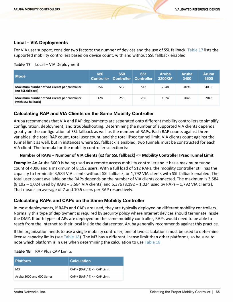
ARUBA MOBILITY CONTROLLERS VALIDATED REFERENCE DESIGN
Local – VIA Deployments
For VIA user support, consider two factors: the number of devices and the use of SSL fallback. Table 17 lists the supported mobility controllers based on device count, with and without SSL fallback enabled.
Calculating RAP and VIA Clients on the Same Mobility Controller
Aruba recommends that VIA and RAP deployments are separated onto different mobility controllers to simplify configuration, deployment, and troubleshooting. Determining the number of supported VIA clients depends greatly on the configuration of SSL fallback as well as the number of RAPs. Each RAP counts against three variables: the total RAP count, total user count, and the total IPsec tunnel limit. VIA clients count against the tunnel limit as well, but in instances where SSL fallback is enabled, two tunnels must be constructed for each VIA client. The formula for the mobility controller selection is:
Number of RAPs + Number of VIA Clients (x2 for SSL fallback) <= Mobility Controller IPsec Tunnel Limit
Example: An Aruba 3600 is being used as a remote access mobility controller and it has a maximum tunnel count of 4096 and a maximum of 8,192 users. With a full load of 512 RAPs, the mobility controller still has the capacity to terminate 3,584 VIA clients without SSL fallback, or 1,792 VIA clients with SSL fallback enabled. The total user count available on the RAPs depends on the number of VIA clients connected. The maximum is 3,584 (8,192 – 1,024 used by RAPs – 3,584 VIA clients) and 5,376 (8,192 – 1,024 used by RAPs – 1,792 VIA clients). That means an average of 7 and 10.5 users per RAP respectively.
Calculating RAPs and CAPs on the Same Mobility Controller
In most deployments, if RAPs and CAPs are used, they are typically deployed on different mobility controllers. Normally this type of deployment is required by security policy where Internet devices should terminate inside the DMZ. If both types of APs are deployed on the same mobility controller, RAPs would need to be able to reach from the Internet to their local inside the datacenter. Aruba generally recommends against this practice.
If the organization needs to use a single mobility controller, one of two calculations must be used to determine license capacity limits (see Table 18). The M3 has a different license limit than other platforms, so be sure to note which platform is in use when determining the calculation to use Table 18.
Table 17 Local – VIA Deployment
Mode620
Controller650
Controller651
ControllerAruba
3200XMAruba 3400
Aruba 3600
Maximum number of VIA clients per controller (no SSL fallback)
256 512 512 2048 4096 4096
Maximum number of VIA clients per controller (with SSL fallback)
128 256 256 1024 2048 2048
Table 18 RAP Plus CAP Limits
Platform Calculation
M3 CAP + (RAP / 2) <= CAP Limit
Aruba 3000 and 600 Series CAP + (RAP / 4) <= CAP Limit
Aruba Networks, Inc. Selecting the Proper Mobility Controller | 65
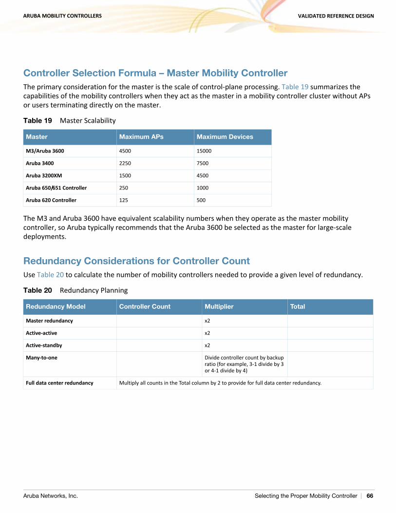
ARUBA MOBILITY CONTROLLERS VALIDATED REFERENCE DESIGN
Controller Selection Formula – Master Mobility ControllerThe primary consideration for the master is the scale of control-plane processing. Table 19 summarizes the capabilities of the mobility controllers when they act as the master in a mobility controller cluster without APs or users terminating directly on the master.
The M3 and Aruba 3600 have equivalent scalability numbers when they operate as the master mobility controller, so Aruba typically recommends that the Aruba 3600 be selected as the master for large-scale deployments.
Redundancy Considerations for Controller CountUse Table 20 to calculate the number of mobility controllers needed to provide a given level of redundancy.
Table 19 Master Scalability
Master Maximum APs Maximum Devices
M3/Aruba 3600 4500 15000
Aruba 3400 2250 7500
Aruba 3200XM 1500 4500
Aruba 650/651 Controller 250 1000
Aruba 620 Controller 125 500
Table 20 Redundancy Planning
Redundancy Model Controller Count Multiplier Total
Master redundancy x2
Active-active x2
Active-standby x2
Many-to-one Divide controller count by backup ratio (for example, 3-1 divide by 3 or 4-1 divide by 4)
Full data center redundancy Multiply all counts in the Total column by 2 to provide for full data center redundancy.
Aruba Networks, Inc. Selecting the Proper Mobility Controller | 66
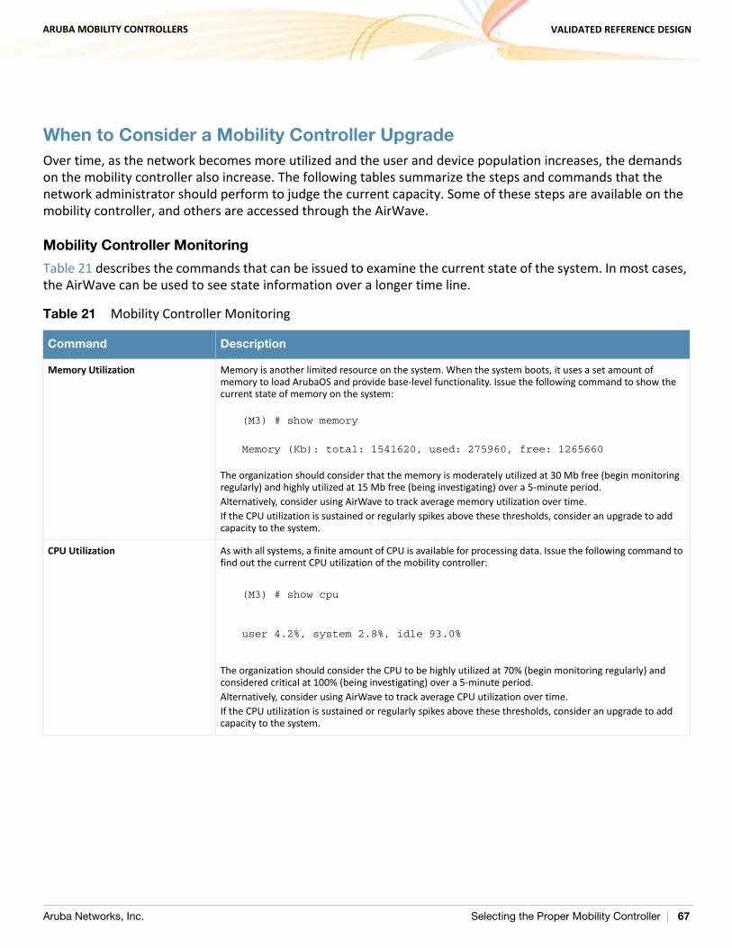
ARUBA MOBILITY CONTROLLERS VALIDATED REFERENCE DESIGN
When to Consider a Mobility Controller UpgradeOver time, as the network becomes more utilized and the user and device population increases, the demands on the mobility controller also increase. The following tables summarize the steps and commands that the network administrator should perform to judge the current capacity. Some of these steps are available on the mobility controller, and others are accessed through the AirWave.
Mobility Controller Monitoring
Table 21 describes the commands that can be issued to examine the current state of the system. In most cases, the AirWave can be used to see state information over a longer time line.
Table 21 Mobility Controller Monitoring
Command Description
Memory Utilization Memory is another limited resource on the system. When the system boots, it uses a set amount of memory to load ArubaOS and provide base-level functionality. Issue the following command to show the current state of memory on the system:
(M3) # show memory
Memory (Kb): total: 1541620, used: 275960, free: 1265660
The organization should consider that the memory is moderately utilized at 30 Mb free (begin monitoring regularly) and highly utilized at 15 Mb free (being investigating) over a 5-minute period.Alternatively, consider using AirWave to track average memory utilization over time.If the CPU utilization is sustained or regularly spikes above these thresholds, consider an upgrade to add capacity to the system.
CPU Utilization As with all systems, a finite amount of CPU is available for processing data. Issue the following command to find out the current CPU utilization of the mobility controller:
(M3) # show cpu
user 4.2%, system 2.8%, idle 93.0%
The organization should consider the CPU to be highly utilized at 70% (begin monitoring regularly) and considered critical at 100% (being investigating) over a 5-minute period. Alternatively, consider using AirWave to track average CPU utilization over time.If the CPU utilization is sustained or regularly spikes above these thresholds, consider an upgrade to add capacity to the system.
Aruba Networks, Inc. Selecting the Proper Mobility Controller | 67
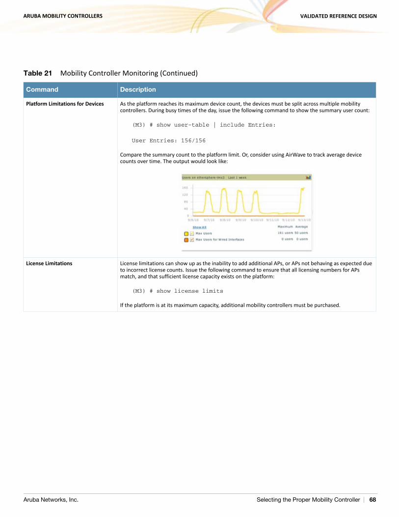
ARUBA MOBILITY CONTROLLERS VALIDATED REFERENCE DESIGN
Platform Limitations for Devices As the platform reaches its maximum device count, the devices must be split across multiple mobility controllers. During busy times of the day, issue the following command to show the summary user count:
(M3) # show user-table | include Entries:
User Entries: 156/156
Compare the summary count to the platform limit. Or, consider using AirWave to track average device counts over time. The output would look like:
License Limitations License limitations can show up as the inability to add additional APs, or APs not behaving as expected due to incorrect license counts. Issue the following command to ensure that all licensing numbers for APs match, and that sufficient license capacity exists on the platform:
(M3) # show license limits
If the platform is at its maximum capacity, additional mobility controllers must be purchased.
Table 21 Mobility Controller Monitoring (Continued)
Command Description
Aruba Networks, Inc. Selecting the Proper Mobility Controller | 68
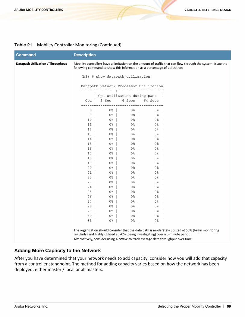
ARUBA MOBILITY CONTROLLERS VALIDATED REFERENCE DESIGN
Adding More Capacity to the Network
After you have determined that your network needs to add capacity, consider how you will add that capacity from a controller standpoint. The method for adding capacity varies based on how the network has been deployed, either master / local or all masters.
Datapath Utilization / Throughput Mobility controllers have a limitation on the amount of traffic that can flow through the system. Issue the following command to show this information as a percentage of utilization:
(M3) # show datapath utilization
Datapath Network Processor Utilization
------+---------+---------+----------+
| Cpu utilization during past |
Cpu | 1 Sec 4 Secs 64 Secs |
------+---------+---------+----------+
8 | 0% | 0% | 0% |
9 | 0% | 0% | 0% |
10 | 0% | 0% | 0% |
11 | 0% | 0% | 0% |
12 | 0% | 0% | 0% |
13 | 0% | 0% | 0% |
14 | 0% | 0% | 0% |
15 | 0% | 0% | 0% |
16 | 0% | 0% | 0% |
17 | 0% | 0% | 0% |
18 | 0% | 0% | 0% |
19 | 0% | 0% | 0% |
20 | 0% | 0% | 0% |
21 | 0% | 0% | 0% |
22 | 0% | 0% | 0% |
23 | 0% | 0% | 0% |
24 | 0% | 0% | 0% |
25 | 0% | 0% | 0% |
26 | 0% | 0% | 0% |
27 | 0% | 0% | 0% |
28 | 0% | 0% | 0% |
29 | 0% | 0% | 0% |
30 | 0% | 0% | 0% |
31 | 0% | 0% | 0% |
The organization should consider that the data path is moderately utilized at 50% (begin monitoring regularly) and highly utilized at 70% (being investigating) over a 5-minute period.Alternatively, consider using AirWave to track average data throughput over time.
Table 21 Mobility Controller Monitoring (Continued)
Command Description
Aruba Networks, Inc. Selecting the Proper Mobility Controller | 69
ARUBA MOBILITY CONTROLLERS VALIDATED REFERENCE DESIGN
Master / Local Clusters
In the campus, a master / local cluster is the most common. In this case, assuming the network is still below the master capacity limit, the simplest method is simply to add additional local controllers. When the locals are added, they synchronize configuration with the master and then start accepting APs.
For the APs, you must decide which APs will terminate on the new master, either newly provisioned APs or a mix of existing and new APs. The location where the APs are deployed helps you decide. APs within a single building should be grouped together on the same mobility controller. If capacity is coming from new buildings, simply terminate the new APs on the new local. If the new capacity is due to increased density in existing deployments, consider moving some existing APs to the new local.
All Masters
For remote deployments, masters usually are deployed in the DMZ. Depending on the scale, they may use AirWave to synchronize configuration files. When more capacity is needed, additional masters must be deployed. Those controllers are configured in two ways:
AirWave synchronization (if present) Modifying the configuration file of the existing master on the new controller to ensure synchronization
In remote deployments, the terminating remote access devices could be split by geography. In this case, existing users, RAPs, or remote controllers in a particular region are moved to the new controller. Consider that the new master may also be deployable in a new datacenter located closer to the users. For all masters in campus deployments, ensure that all APs in the same building terminate to the same master. If APs from different masters will be able to hear each other, use AirWave and WMS offload to ensure correct operation of the valid AP list.
Aruba Networks, Inc. Selecting the Proper Mobility Controller | 70
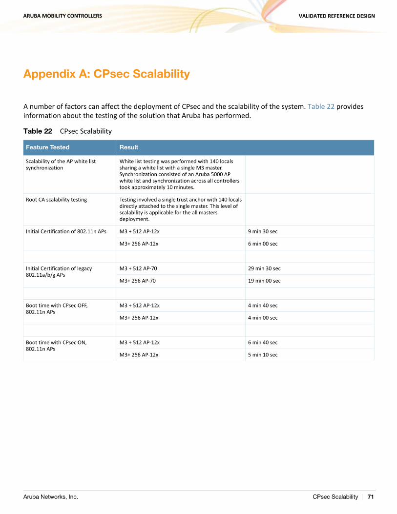
ARUBA MOBILITY CONTROLLERS VALIDATED REFERENCE DESIGN
Appendix A: CPsec Scalability
A number of factors can affect the deployment of CPsec and the scalability of the system. Table 22 provides information about the testing of the solution that Aruba has performed.
Table 22 CPsec Scalability
Feature Tested Result
Scalability of the AP white list synchronization
White list testing was performed with 140 locals sharing a white list with a single M3 master. Synchronization consisted of an Aruba 5000 AP white list and synchronization across all controllers took approximately 10 minutes.
Root CA scalability testing Testing involved a single trust anchor with 140 locals directly attached to the single master. This level of scalability is applicable for the all masters deployment.
Initial Certification of 802.11n APs M3 + 512 AP-12x 9 min 30 sec
M3+ 256 AP-12x 6 min 00 sec
Initial Certification of legacy 802.11a/b/g APs
M3 + 512 AP-70 29 min 30 sec
M3+ 256 AP-70 19 min 00 sec
Boot time with CPsec OFF, 802.11n APs
M3 + 512 AP-12x 4 min 40 sec
M3+ 256 AP-12x 4 min 00 sec
Boot time with CPsec ON, 802.11n APs
M3 + 512 AP-12x 6 min 40 sec
M3+ 256 AP-12x 5 min 10 sec
Aruba Networks, Inc. CPsec Scalability | 71

ARUBA MOBILITY CONTROLLERS VALIDATED REFERENCE DESIGN
Aruba Networks, Inc. CPsec Scalability | 72
ARUBA MOBILITY CONTROLLERS VALIDATED REFERENCE DESIGN
Appendix B: AP Failover Times
Table 23 on page 74 and Table 24 on page 74 show failover times for APs failing over in an active-active deployment. This table was developed using two test cases:
Test case 1: The test starts with APs distributed evenly between two mobility controllers. The test ends when all APs have completed their transition from the disconnected mobility controller to the remaining mobility controller.
Test case 2: This test takes the first test case and includes APs and clients failing over between the two mobility controllers. Test case 2 represents a “worst case scenario.” This test starts with APs and clients evenly distributed between two mobility controllers. The test ends when the last client connection is re-established on the remaining mobility controller. Actual client experience will vary between a few seconds and the maximum value stated.
The client reauthentication rate is affected by a variety of factors outside of the WLAN infrastructure. In this scenario, the clients dominate the resultant failover times. Client reauthentication can vary considerably based on these things:
Client supplicant: Problems with the client supplicant can include slow authentication and noncached credentials.
Client driver: The client NIC card is slow to recognize that the network connection has been interrupted and is again available. The NIC card takes longer than expected to attempt to reconnect to the network.
Authentication type: Different authentication types have different speeds for reauthentication. An example is 802.1X is more involved than an open network.
Insufficient AAA infrastructure: When a large number of clients attempt to reconnect to the network at the same time, the AAA infrastructure, such as RADIUS and LDAP servers, can become overwhelmed.
Insufficient backend infrastructure: Bottlenecks in the internal infrastructure can lead to longer response times and dropped packets, which creates longer authentication times.
N O T E
These numbers are based on active-active redundancy, with half of the APs and users active on each mobility controller. For active-standby or N+1 redundancy, expect that failover times and client authentication can take 25% to 100% longer for each set of numbers. The longer times are caused by the greater number of APs and clients that fail over to the backup controller. For example, in the largest test case, 256 APs need to fail over. In the active-standby model, 512 APs need to fail over.
Aruba Networks, Inc. AP Failover Times | 73
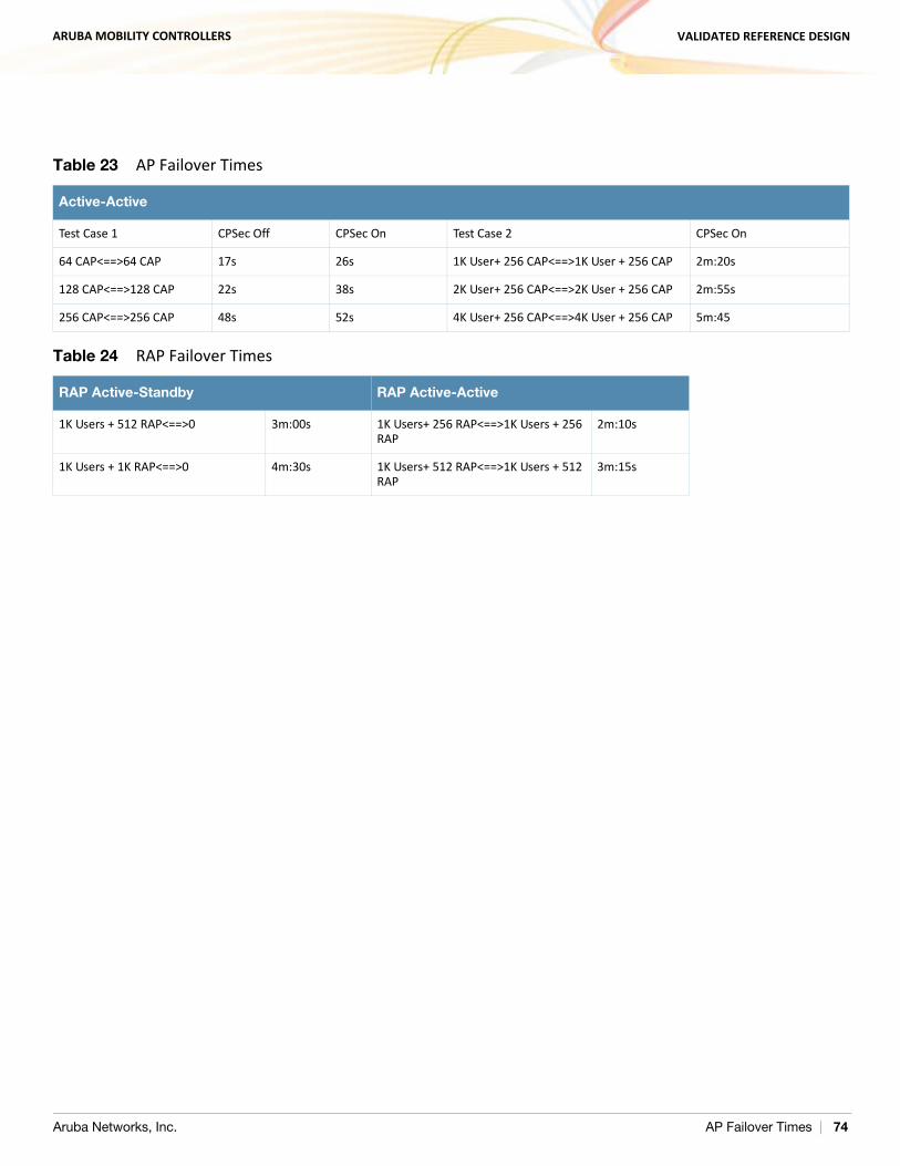
ARUBA MOBILITY CONTROLLERS VALIDATED REFERENCE DESIGN
Table 23 AP Failover Times
Active-Active
Test Case 1 CPSec Off CPSec On Test Case 2 CPSec On
64 CAP<==>64 CAP 17s 26s 1K User+ 256 CAP<==>1K User + 256 CAP 2m:20s
128 CAP<==>128 CAP 22s 38s 2K User+ 256 CAP<==>2K User + 256 CAP 2m:55s
256 CAP<==>256 CAP 48s 52s 4K User+ 256 CAP<==>4K User + 256 CAP 5m:45
Table 24 RAP Failover Times
RAP Active-Standby RAP Active-Active
1K Users + 512 RAP<==>0 3m:00s 1K Users+ 256 RAP<==>1K Users + 256 RAP
2m:10s
1K Users + 1K RAP<==>0 4m:30s 1K Users+ 512 RAP<==>1K Users + 512 RAP
3m:15s
Aruba Networks, Inc. AP Failover Times | 74
ARUBA MOBILITY CONTROLLERS VALIDATED REFERENCE DESIGN
Appendix C: Scalability in the All Masters Deployment Model
The following scaling numbers apply to the all master deployments in ArubaOS 6.1 / AirWave 7.3: An all-master deployment, where APs are spread across multiple mobility controllers but are in the same
physical location, must be under the control of a single AirWave instance. Currently these deployments scale to 2500 devices. WMS offload must be enabled on the mobility controllers to allow the AirWave to manage valid AP lists.
The following limitations exist in an all-master deployment:
WMS offload must be enabled, but the WMS data is not shared between AirWave instances. Currently deployments are limited to 5000 devices.
Currently, configuration cannot be synchronized across multiple AirWave instances. If multiple AirWave servers are required, their configurations must be kept in sync manually.
Depending on polling intervals, it can take some time for AirWave to relearn that users and APs have moved to a new master. Assume at least one polling cycle
before the state is reflected on the AirWave. If the status of a device changes on the controller, but it changes again before AirWave polls, the controller and AirWave may contain different state
information. This situation can occur with classification, but is more likely with user status. If the user roams more than once between polls, the AirWave will have only the most recent status and will not have the complete trail.
When a failover occurs, and a client that was on the failed controller roams to the new controller, the client disappears from AirWave until polling finds the client again. The client is not
on the user page on AirWave and is not on the heat map. Locations that use multiple APs spread across multiple masters result in a wider margin of error than
when a single master/local cluster is enabled. VisualRF heat maps can take multiple polling cycles to update after APs fail from one master to the
backup master.
Aruba Networks, Inc. Scalability in the All Masters Deployment Model | 75

ARUBA MOBILITY CONTROLLERS VALIDATED REFERENCE DESIGN
Aruba Networks, Inc. Scalability in the All Masters Deployment Model | 76
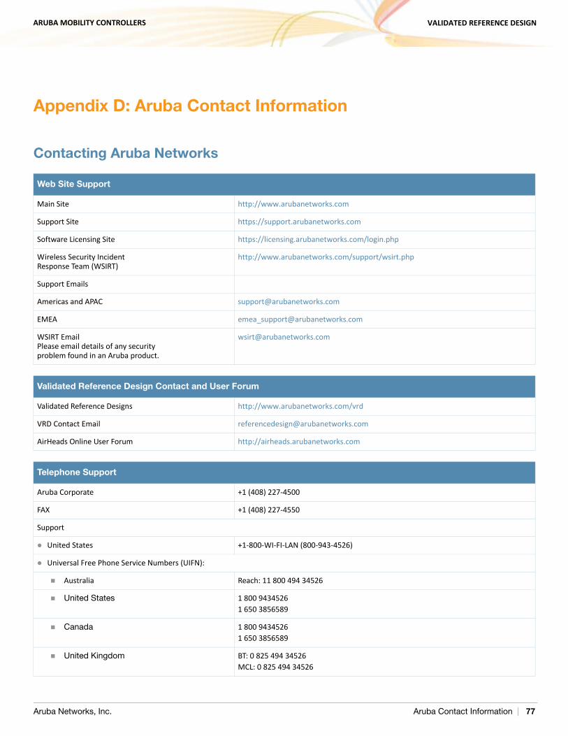
ARUBA MOBILITY CONTROLLERS VALIDATED REFERENCE DESIGN
Appendix D: Aruba Contact Information
Contacting Aruba Networks
Web Site Support
Main Site http://www.arubanetworks.com
Support Site https://support.arubanetworks.com
Software Licensing Site https://licensing.arubanetworks.com/login.php
Wireless Security IncidentResponse Team (WSIRT)
http://www.arubanetworks.com/support/wsirt.php
Support Emails
Americas and APAC [email protected]
EMEA [email protected]
WSIRT EmailPlease email details of any securityproblem found in an Aruba product.
Validated Reference Design Contact and User Forum
Validated Reference Designs http://www.arubanetworks.com/vrd
VRD Contact Email [email protected]
AirHeads Online User Forum http://airheads.arubanetworks.com
Telephone Support
Aruba Corporate +1 (408) 227-4500
FAX +1 (408) 227-4550
Support
United States +1-800-WI-FI-LAN (800-943-4526)
Universal Free Phone Service Numbers (UIFN):
Australia Reach: 11 800 494 34526
United States 1 800 94345261 650 3856589
Canada 1 800 94345261 650 3856589
United Kingdom BT: 0 825 494 34526MCL: 0 825 494 34526
Aruba Networks, Inc. Aruba Contact Information | 77
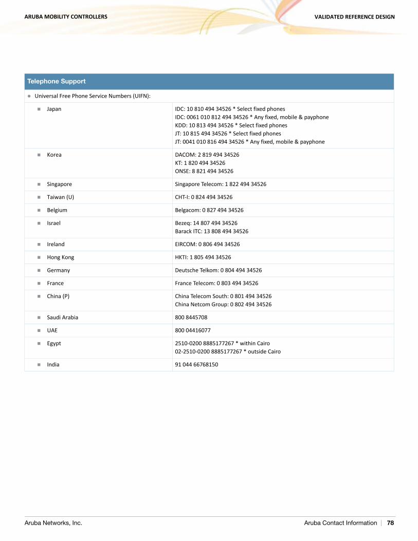
ARUBA MOBILITY CONTROLLERS VALIDATED REFERENCE DESIGN
Universal Free Phone Service Numbers (UIFN):
Japan IDC: 10 810 494 34526 * Select fixed phonesIDC: 0061 010 812 494 34526 * Any fixed, mobile & payphoneKDD: 10 813 494 34526 * Select fixed phonesJT: 10 815 494 34526 * Select fixed phonesJT: 0041 010 816 494 34526 * Any fixed, mobile & payphone
Korea DACOM: 2 819 494 34526KT: 1 820 494 34526ONSE: 8 821 494 34526
Singapore Singapore Telecom: 1 822 494 34526
Taiwan (U) CHT-I: 0 824 494 34526
Belgium Belgacom: 0 827 494 34526
Israel Bezeq: 14 807 494 34526Barack ITC: 13 808 494 34526
Ireland EIRCOM: 0 806 494 34526
Hong Kong HKTI: 1 805 494 34526
Germany Deutsche Telkom: 0 804 494 34526
France France Telecom: 0 803 494 34526
China (P) China Telecom South: 0 801 494 34526China Netcom Group: 0 802 494 34526
Saudi Arabia 800 8445708
UAE 800 04416077
Egypt 2510-0200 8885177267 * within Cairo02-2510-0200 8885177267 * outside Cairo
India 91 044 66768150
Telephone Support
Aruba Networks, Inc. Aruba Contact Information | 78