Embed Size (px)
Citation preview
International Conference on Renewable Energies and Power Quality (ICREPQ’13)
Bilbao (Spain), 20th to 22
th March, 2013
exÇxãtuÄx XÇxÜzç tÇw cÉãxÜ dâtÄ|àç ]ÉâÜÇtÄ (RE&PQJ)
ISSN 2172-038 X, No.11, March 2013
Simulation model of a protection scheme for active distribution networks
F. Belloni
1, C. Chiumeo
1, C. Gandolfi
1, S. Pugliese
2
1 Ricerca sul Sistema Energetico – RSE S.p.A.
Via Rubattino 54, 20134, Milano (Italy)
Phone number:+39 02 39925796 2 A2A Reti Elettriche S.p.A.
Via Ponte Nuovo 100, 20128, Milano (Italy)
Phone number:+39 02 77205605
e-mail: [email protected], [email protected], [email protected], [email protected]
Abstract. The growing trend of installed power from
Distributed Generators (DG) in distribution networks is giving rise to new issues in grid operations. In particular, the interaction between DG and grid protections can cause nuisance trips, unwanted island operations and, in general, worsening of power quality. The paper discusses a possible protection scheme suited for active networks and implementing logic selectivity. The proposed approach is based on directional protections
coordinated through communications. Simulation models of an urban Medium Voltage (MV) distribution grid, of distributed generators and of the employed types of protections have been developed in the DIgSILENT Power Factory environment. Digital simulations confirms the effectiveness of the proposed approach.
Key words
Active networks, grid protections, logic selectivity.
1. Introduction
A number of different drivers, such as improvements of
power electronics, reduction of transmission and
distribution costs, environmental issues and needs of
diversifying power sources, is pushing a rapid increase of
Distributed Generators (DG) connected to Medium
Voltage (MV) distribution grids. The presence of large
amounts of DG can interact with the grid and can have
major impacts on the power quality. Some of the main interactions between DG and distribution grids are:
• Reversal of power flow;
• Harmonic pollution;
• Voltage increase;
• Voltage variations;
• Flicker;
• Nuisance trips/failures of grid protections;
• Unwanted island operations [1, 2].
The paper, focusing on the last two phenomena, proposes a
possible protection scheme suited for active distribution
grids [3]. Such a scheme makes use of directional line overcurrent relays and directional earth relays and
introduces communications among grid protections and
interface protections of DG [4]. The main goals of the
proposed solutions are: management of bidirectional
power flows, logic selectivity, faulty line segment
selection, reduced risk of unwanted island.
The paper deals with the implementation in the
DIgSILENT1 Power Factory digital simulation
environment of the proposed protection scheme. To this
purpose, models of a typical urban MV distribution grid, of grid protections, of DG interface protections and of the
communications systems have been developed. Digital
simulations were performed to show the effectiveness of
the proposed solution.
2. Operation principles of the protection
scheme The protection scheme typically employed in a MV
distribution feeder is based on a main protection,
including an overcurrent relay (non-directional) and a
directional earth relay, installed at the primary substation
level together with a circuit breaker [5]. In case of fault
along the line, the protection trips disconnecting the
whole feeder from the main grid. In order to reduce the risk of unwanted island operations, each generator is
equipped with an interface protection, which trips in case
of under/over-voltage or frequency variations larger than
a dead band around the nominal value.
The main drawbacks of this protection scheme are:
• Disconnection of the entire feeder in case of
fault;
• Possible disconnection of generators also in non-
faulted lines;
• Possible unwanted island operation (the
interface protection does not recognize the loss of main);
• Reclosure procedures affecting the whole feeder.
In the proposed protection scheme, the distribution feeder
is instead subdivided into two or more segments. A line
protection and a circuit breaker are installed at the
beginning of each line segment. Each protection is
composed by a directional line overcurrent relay and a
1 DIgSILENT Power Factory, version 14.1.4.
https://doi.org/10.24084/repqj11.229 93 RE&PQJ, Vol.1, No.11, March 2013

directional earth relay. Line protections can exchange
messages, and, in particular, two different logic commands
can be sent/received:
• BLOCK: the receiving protection is disabled, so
that it cannot trip;
• TRIP: the receiving protection is forced to trip,
independently of its settings.
Also DG interface protections should be modified to be
adapted. In particular, they should accept TRIP commands and they should provide two different dead bands around
the frequency nominal value, as shown in Fig. 1.
The wider dead band is employed in standard conditions,
while the narrower is automatically activated only in case
the fault is located near the generator [6].
The operation principles of the proposed protection
scheme are illustrated in Fig. 2. Two directional
protections, one for each possible direction, are installed
at the primary substation level and at the secondary
substations, as shown in Fig. 2. In the example, a fault
occurs in the second line segment. Protections P0 and P1B start due to fault current supplied
by the primary substation; P2A (and P3A, if the line has
more segments than in Fig. 2) also possibly starts, due to
the fault current supplied by DG2.
Fig. 1. Narrow and wide frequency bands of the DG interface protections.
Fig. 2. Illustration of the operation principles of the protection scheme.
In the proposed scheme:
1. P1B send a BLOCK message to P0, i.e. in the
opposite direction to respect to the fault current;
the same holds for P2A and P3A; 2. P0 and P3A, being blocked, do not trip, while
P1B and P2A can trip;
3. if P1B is the first protection that trips, it sends a
TRIP signal to P2A which is forced to trip too;
4. a TRIP signal is sent to all DG connected
downstream P1B, forcing disconnections.
In such a way, the fault is unsupplied and the faulted line
segment is detected by the tripping of P1B and P2A. The
line segments upstream the faulted one remain supplied
and the relevant DG remain connected if it has Fault Ride
Through (FRT) capability. In case of communication failure, the protection P0 does not receive the BLOCK
signal and trips, disconnecting the whole distribution
feeder. In such a way, the protection scheme is still
functional, even though with reduced performances2.
The proposed protection scheme has two main drawbacks:
• Protection set up must take into account
communication time delays;
2 In this case, performances are the same as those of “present”
protection system.
• Protections and circuit breakers should be
duplicated along the line to reduce the load
disconnected (Fig. 2).
3. Simulation models For the study presented in the paper, the following
DIgSILENT Power Factory simulation models have been
developed:
• MV distribution grid;
• Distributed Generators;
• Directional line protections and directional earth
protections;
• DG interface protections;
• Communication channels with adjustable delays.
B. Distribution grid
The scheme of an urban MV distribution network of the
Italian DSO A2A Reti Elettriche S.p.A. has been
considered. Even though quite general, the selected
network has some peculiarities, such as the presence of a
23 kV level and a 9 kV level and the connection of two 23 kV busbars with eight parallel lines. The network
scheme is represented in Fig. 3, where each voltage level
is represented with a different colour (GREEN: 9 kV,
RED: 23 kV, BLUE: 220 kV). The new type of
https://doi.org/10.24084/repqj11.229 94 RE&PQJ, Vol.1, No.11, March 2013

directional protections are installed in the two zones
circled in red and green, while typical line protections are
installed at the beginning of all the other distribution
feeders. Also, maximum current protections are installed at
the secondary side of each transformer. The neutral point
of the MV network is not connected to earth.
C. Distributed generators
Photovoltaic distributed generation is considered in the study. DiGSILENT native models of PV generators are
employed, with custom controls. In particular, during
steady state, PV generators supply their rated power,
while during a voltage dip they supply reactive current
∆Iq proportional to the voltage drop ∆V, according to the formula:
NN
q
V
Vk
I
I ∆=
∆ (1)
where IN is the rated current, VN the rated voltage and
k≥2 [7-10]. The employed model does not take into
account the presence of power electronic switches.
Fig. 3. DigSILENT MV network model.
D. Directional protections
Line protections are implemented as multifunction
protections which incorporate both directional overcurrent
and directional earth protections. The model, implemented
within the DiGSILENT Power Factory environment, also
allows the dispatch and reception of BLOCK and TRIP
signals.
The directional overcurrent relay can be set up with three different current threshold levels, each one with a different
time delay. The directional earth relay has a current and a
voltage threshold with configurable angular sector and
time delay.
The BLOCK signal is dispatched when the protection
starts, while the TRIP signal when the protection actually
trips.
Circuit breakers have been modelled too. In particular, a
mechanical time delay of 80 ms between the opening
command receipt and the actual opening has been
considered.
E. Interface protections
The block scheme of the interface protection model is
represented in Fig. 4.
According to the latest Italian standards [6], the model
integrates three differwent protection functions:
• Over/under-voltage;
• Over/under-frequency (wide band) – always
active;
• Over/under frequency (narrow band) – activated
only if the grid voltage negative or zero
sequences exceed a threshold value or the
positive sequence decrease below a given limit3.
Fig. 4. DIgSILENT implementation of an interface protection.
An additional overvoltage protection should be present
according to Italian standards, but it is not included in the
model since it considers very slow voltage variations.
3 This allows to recognize a MV fault from a frequency variation
generated in the HV transmission network.
https://doi.org/10.24084/repqj11.229 95 RE&PQJ, Vol.1, No.11, March 2013

F. Communication channel
Communication exchanges among protections are
represented in the DIgSILENT block scheme reported in
Fig. 5, where an adjustable time delay is inserted along
each signal path to simulate communication lags.
G. Protection settings
Traditional line protections and DG interface protections
are set according to typical Italian thresholds, as reported in Table I.
Fig. 5. Communications channel model.
Table I. Protections settings.
Protection Threshold Intentional delay
Line overcurrent @9 kV
51.S1 1.5 Inom 1 s
51.S2 1 kA 0.25 s
51.S3 2 kA 0 s
Line overcurrent @23 kV
51.S1 1.5 Inom 1 s
51.S2 0.8 kA 0.25 s
51.S3 1.4 kA 0 s
Transformer secondary side overcurrent
51 1.6 Inom,2 1.5 s
Directional earth @9 kV*
67N 12 mA 0.4 s
59N 0.4 V 0.4 s
Directional earth @23 kV*
67N 12 mA 0.4 s
59N 0.8 V 0.4 s
Interface protection
59 1.15 VN 0.2 s
27 0.4 VN 0.2 s
81>.S1 50.3 Hz 0.1 s
81>.S2 51.5 Hz 0.1 s
81<.S1 49.7 Hz 0.1 s
81<.S2 47.5 Hz 0.1 s
*Settings valid also for directional earth relays of the new
protection models.
The directional line relays have been set similarly to the traditional line overcurrent relay, but adding an intentional
delay to the 51.S3 protection in order to taking into
account possible communication time lags. In this paper, a
typical communication time lag of 20 ms was supposed,
so that an intentional time delay of 30 ms was added to the
overcurrent protection. This time lag is typical of fiber
optics based communications.
4. Simulation results The presented protection scheme was tested through
digital simulations in the DIgSILENT environment.
Different case studies were considered, in order to assess both the logic selectivity among the new type of
protections and the interactions with typical protection
scheme. All simulations are performed adopting the
network scheme of Fig. 3.
A. Poly-phase fault on the line equipped with the
proposed protections scheme
A three phase short circuit was simulated on the 9 kV line
with about 2 MVA of DG connected. It is located in the
second line segment, at 3 km from the 23 kV/9 kV
transformer. The simulation time begins at t = -100 ms
and the fault occurs at t = 0 s. The time-overcurrent plots of the directional line protections are reported in Fig. 6
together with relevant short circuit current values.
Fig. 6. Time-overcurrent plots of directional line protection.
There are reported the plots relevant to protections installed at the primary substaion level (BLUE), at the beginning of the
faulted line (RED) and along the same line (GREEN). Red and green curves are overlapping.
According to the plots of Fig. 6, if no logic selectivity is
applied, both the protections installed on the faulted line
would trip, since the short circuit current, shown as a red
and a green (not visible because overlapping to the red
one) vertical lines, intersects the protection characteristics
at the same time value (reported on the y-axes). With the
proposed approach, the protection closer to the fault is
instead the only left active, minimizing the number of
disconnected users. In this example, also DG are
disconnected from the feeder, since they are located
downstream the fault. Fig. 7 reports the following simulation results:
8a) starting status of the protection at the primary
substation (220/23 kV);
8b) starting status of the protection at the beginning
of the MV line (9 kV);
8c) starting status of the protection closer to the fault;
8d) blocking signal (RED) and tripping status
(GREEN) of the protection at the primary
substation;
8e) blocking signal (RED) and tripping status
(GREEN) of the protection at the beginning of
the MV line; 8f) blocking signal (RED) and tripping status
(GREEN) of the protection closer to the fault.
https://doi.org/10.24084/repqj11.229 96 RE&PQJ, Vol.1, No.11, March 2013
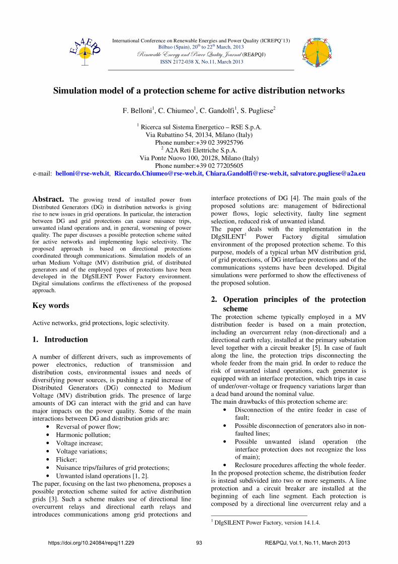
Only the protection closer to the fault actually trips,
forcing the tripping of both the DG interface protection
and of the directional line protection installed downstream
the feeder. The final status of the three 9 kV feeders is
shown in Fig. 8, where the open breakers are highlighted
with red circles.
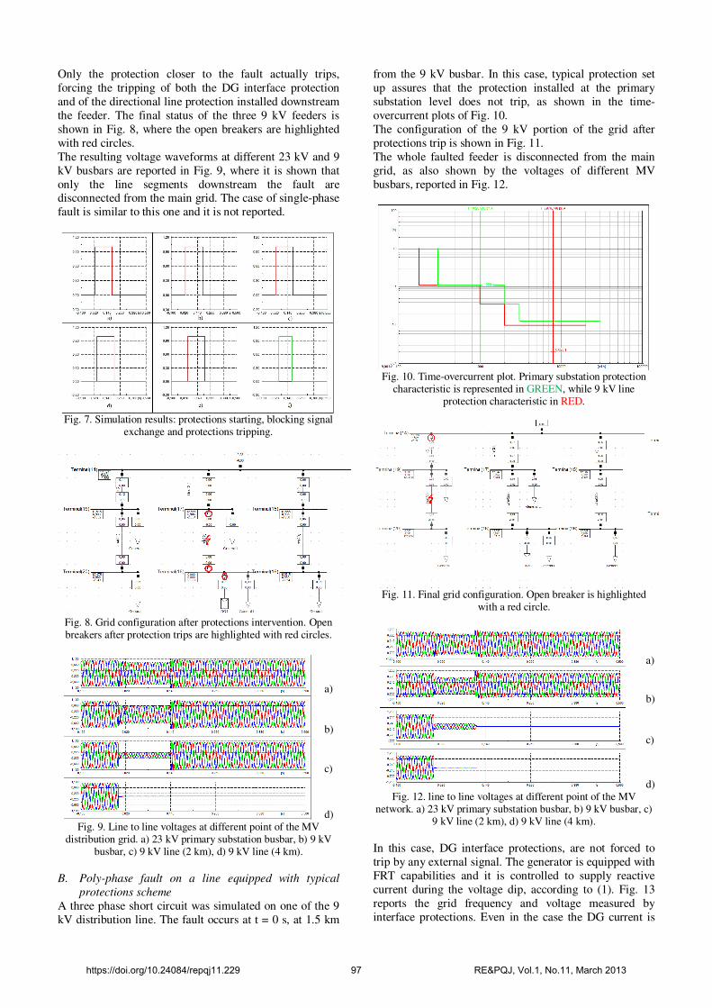
The resulting voltage waveforms at different 23 kV and 9
kV busbars are reported in Fig. 9, where it is shown that
only the line segments downstream the fault are disconnected from the main grid. The case of single-phase
fault is similar to this one and it is not reported.
Fig. 7. Simulation results: protections starting, blocking signal
exchange and protections tripping.
Fig. 8. Grid configuration after protections intervention. Open breakers after protection trips are highlighted with red circles.
a)
b)
c)
d) Fig. 9. Line to line voltages at different point of the MV
distribution grid. a) 23 kV primary substation busbar, b) 9 kV busbar, c) 9 kV line (2 km), d) 9 kV line (4 km).
B. Poly-phase fault on a line equipped with typical
protections scheme
A three phase short circuit was simulated on one of the 9
kV distribution line. The fault occurs at t = 0 s, at 1.5 km
from the 9 kV busbar. In this case, typical protection set
up assures that the protection installed at the primary
substation level does not trip, as shown in the time-
overcurrent plots of Fig. 10.
The configuration of the 9 kV portion of the grid after
protections trip is shown in Fig. 11.
The whole faulted feeder is disconnected from the main
grid, as also shown by the voltages of different MV
busbars, reported in Fig. 12.
Fig. 10. Time-overcurrent plot. Primary substation protection
characteristic is represented in GREEN, while 9 kV line protection characteristic in RED.
Fig. 11. Final grid configuration. Open breaker is highlighted
with a red circle.
a)
b)
c)
d) Fig. 12. line to line voltages at different point of the MV
network. a) 23 kV primary substation busbar, b) 9 kV busbar, c) 9 kV line (2 km), d) 9 kV line (4 km).
In this case, DG interface protections, are not forced to
trip by any external signal. The generator is equipped with
FRT capabilities and it is controlled to supply reactive
current during the voltage dip, according to (1). Fig. 13
reports the grid frequency and voltage measured by
interface protections. Even in the case the DG current is
https://doi.org/10.24084/repqj11.229 97 RE&PQJ, Vol.1, No.11, March 2013

sufficient to make the relevant line protection start, logic
selectivity and communications avoid nuisance trips.
Fig. 13. Grid frequency and voltage measured by DG interface
protection, compared with relevant threshold values.
C. Poly-phase fault on a 23 kV line
It was simulated a three phase short circuit occurring on
one of eight parallel 23 kV lines outgoing from the
primary substation MV busbar. The faulted line is selected
by the trip of the protection installed at the feeder starting point which also forces the trip of the protection at the end
of the line. In particular, the forced trip of this latter
protection avoids the fault being supplied from the
primary substation through the healthy lines. Fig. 14
shows the trip signal dispatched by the “upper” protection
and received by the “lower” one, with 20 ms delay, and
the fault currents.
Fig. 14. Line protections coordination. a) time delay between
dispatched and received TRIP signals; b) fault currents from the primary substation; c) fault currents through healthy lines.
5. Conclusions A possible protection scheme suited for mixed passive and
active distribution networks has been presented in the
paper. It makes use of directional line relays, directional
earth relays and Distributed Generators interface
protections, coordinated through communications. The
proposed scheme offers some advantages in terms of:
logic selectivity, dealing with bidirectional power flows,
optimal management of DG disconnections, faulted line
segment selection, and integration with pre-existing
protection schemes. On the other hand, the proposed
solution has some drawbacks due to communication time lags and need of redundancy.
Digital simulations, performed with DIgSILENT Power
Factory, shows the effectiveness of the proposed approach
for different type of faults. For simulations, a grid model
inclusive of protections and distributed generators has
been developed.
Future works will deal with the analysis of the proposed
protection scheme in a MV meshed network.
Acknowledgement This work has been financed by the Research Fund for the
Italian Electrical System under the Contract Agreement
between RSE S.p.A. and the Ministry of Economic
Development - General Directorate for Nuclear Energy,
Renewable Energy and Energy Efficiency in compliance
with the Decree of March 8, 2006.
References [1] F.J. Pazos, "Operational experience and field tests on islanding event caused by large photovoltaic plants", 21th International Conference on Electricity Distribution, CIRED2011, 6-9 June, Frankfurt, Germany [2] Z. Ye, A. Kolwalkar, Y. Zhang, P. Du, R. Walling,
"Evaluation of anti-islanding schemes based on non detection zone concept", IEEE 34th Annual Power Electronics Specialist Conference, PESC '03., 15-19 June 2003, Niskayuna, NY, USA, Vol. 4, pp. 1735-1741 [3] F. Belloni, R. Chiumeo, C. Gandolfi, A. Villa, “A protection coordination scheme for active distribution networks”, 47th International Universities’ Power Engineering Conference, UPEC 2012, 4-7 September 2012, London, UK, pp.1-6
[4] R. Calone, A. Cerretti, A. Fatica, "Evolution of fault locator on MV distribution networks: from simple stand alone device, to a sophisticated strategic component of the SMART GRID control system", 21th International Conference on Electricity Distribution, CIRED2011, 6-9 June, Frankfurt, Germany [5] A. Cerretti, G. Scrosati, L. Consiglio, "Upgrade of ENEL MV network automation to improve performances in presence of faults and to deal DG", 21th International Conference on Electricity Distribution, CIRED2011, 6-9 June, Frankfurt,
Germany [6] A.A.V.V., "Codice di trasmissione, dispacciamento, sviluppo e sicurezza della rete", web: http://www.terna.it/ - in Italian language [7] R. Chiumeo, C. Gandolfi, “A Three Phase Photovoltaic Power System Connected to the MV Network: Behaviour during Voltage Dips”, ICREPQ 2011, 13-15 April, Las Palmas di Gran Canaria, Spain, pp.1-6
[8] A.A.V.V., "Transmission Code 2007", web: http://www.vde.com/ [9] F:J. Pazos, "Power frequency overvoltages generated by solar plants", 20th International Conference on Electricity Distribution, CIRED2009, 8-11 June 2009, Prague, Czech Republic, pp. 1-4 [10] F. Belloni, C. Chiappa, R. Chiumeo, P. Groppelli, A. Villa, “Sistemi elettronici di potenza per la connessione della
generazione distribuita alla rete elettrica: analisi del comportamento a fronte dei disturbi di rete”, final report “Ricerca di Sistema”, web: http://www.rse-web.it - in Italian language
https://doi.org/10.24084/repqj11.229 98 RE&PQJ, Vol.1, No.11, March 2013