Embed Size (px)
Citation preview
International Conference on Renewable Energies and Power Quality (ICREPQ’16) Madrid (Spain), 4th to 6th May, 2016
Renewable Energy and Power Quality Journal (RE&PQJ)
ISSN 2172-038 X, No.14 May 2016
Reverse supply of an AC distribution feeder through a Medium Voltage DC link
F. Belloni1, R. Chiumeo1, C. Gandolfi1, D. Palladini1, A. Villa1
1 Ricerca sul Sistema Energetico – RSE s.p.a. via Rubattino 54, 20134, Milano (Italy)
Phone/Fax number: +39 02 39925796, e-mail: [email protected], riccardo.chiumeo@ rse-web.it, cgandolfi@ rse-web.it, [email protected], [email protected]
Abstract. Medium Voltage Direct Current grids seems a promising solution for meshing AC grids, in order to enhance their distributed generators hosting capacity. The DC link is created through power electronics interface converters, which allow implementing different functions through suited control strategies. In particular, the paper investigate the possibility of supplying AC connected loads in island operation, i.e. separated from the mains, when a fault occurs in one of the AC grids. A 5 MW link is considered in the paper. Relevant power converters has been designed and modelled in a digital simulation environment. A complex control strategy for the management of the complete process of island supply and reconnection to mains, involving also communication between converters and grid protections, has been implemented and tested through simulations. Simulation results confirms the effectiveness of the proposed approach.
Key words Medium Voltage Direct Current link, power electronics, island operations, reverse supply, meshed distribution grids.
1. Introduction The majority of electric distribution systems is nowadays in Alternate Current (AC), due to the fact that most of generators and loads are in the form of AC, and transformers can conveniently and efficiently step up or down the voltage level [1]. However, some emerging driving factors are pushing the development of Direct Current (DC) distribution and transmissions system: the technological development of power electronics
components and devices, which allow an efficient, reliable and convenient processing of electric power in DC form;
the spreading of Distributed Generators (DG), such as photovoltaic generators, synchronous magnet wind generators and micro-turbines, which are either in DC form or should be interfaced to the grid through power electronic converters;
the rising diffusion of storage systems, electrochemical or fuel cell based, which are inherently in the DC form;
the higher efficiency and transport capacity of DC distribution and transmission systems, due to the absence of reactive power and skin effect.
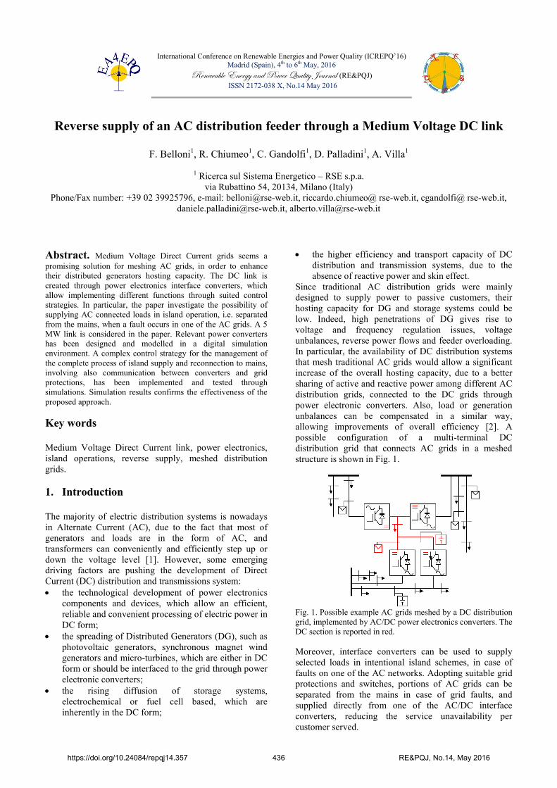
Since traditional AC distribution grids were mainly designed to supply power to passive customers, their hosting capacity for DG and storage systems could be low. Indeed, high penetrations of DG gives rise to voltage and frequency regulation issues, voltage unbalances, reverse power flows and feeder overloading. In particular, the availability of DC distribution systems that mesh traditional AC grids would allow a significant increase of the overall hosting capacity, due to a better sharing of active and reactive power among different AC distribution grids, connected to the DC grids through power electronic converters. Also, load or generation unbalances can be compensated in a similar way, allowing improvements of overall efficiency [2]. A possible configuration of a multi-terminal DC distribution grid that connects AC grids in a meshed structure is shown in Fig. 1.
Fig. 1. Possible example AC grids meshed by a DC distribution grid, implemented by AC/DC power electronics converters. The DC section is reported in red. Moreover, interface converters can be used to supply selected loads in intentional island schemes, in case of faults on one of the AC networks. Adopting suitable grid protections and switches, portions of AC grids can be separated from the mains in case of grid faults, and supplied directly from one of the AC/DC interface converters, reducing the service unavailability per customer served.
https://doi.org/10.24084/repqj14.357 436 RE&PQJ, No.14, May 2016
The present paper is focused on this latter functionality offered by Medium Voltage Direct Current (MVDC) links meshing MV distribution grids. In the paper, a 5 MW two terminal MVDC link between two AC distribution grids is designed and modeled in the ATPDraw environment, together with its controls, both for steady state operations and for the reverse supply of loads in island mode, when AC grid faults occur. Digital simulation results are reported to show the effectiveness of this approach.
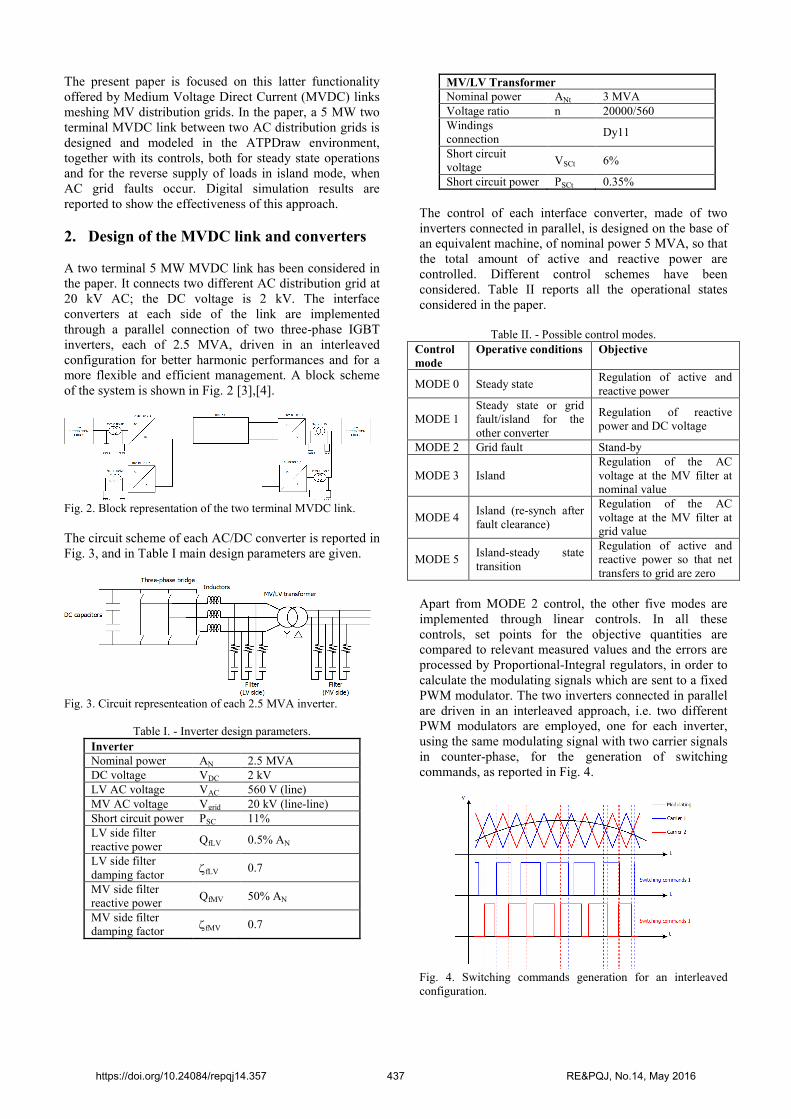
2. Design of the MVDC link and converters A two terminal 5 MW MVDC link has been considered in the paper. It connects two different AC distribution grid at 20 kV AC; the DC voltage is 2 kV. The interface converters at each side of the link are implemented through a parallel connection of two three-phase IGBT inverters, each of 2.5 MVA, driven in an interleaved configuration for better harmonic performances and for a more flexible and efficient management. A block scheme of the system is shown in Fig. 2 [3],[4].
Fig. 2. Block representation of the two terminal MVDC link. The circuit scheme of each AC/DC converter is reported in Fig. 3, and in Table I main design parameters are given.
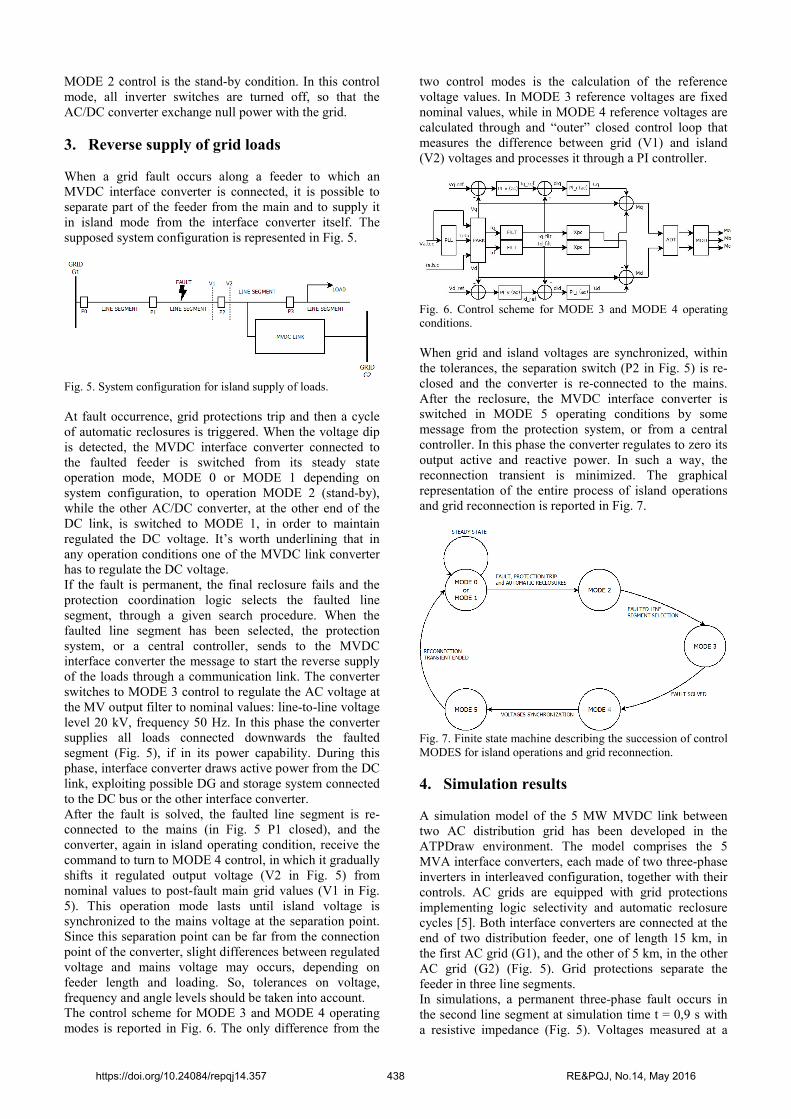
Fig. 3. Circuit representeation of each 2.5 MVA inverter.
Table I. - Inverter design parameters.
Inverter Nominal power AN 2.5 MVA DC voltage VDC 2 kV LV AC voltage VAC 560 V (line) MV AC voltage Vgrid 20 kV (line-line) Short circuit power PSC 11% LV side filter reactive power
QfLV 0.5% AN
LV side filter damping factor
fLV 0.7
MV side filter reactive power
QfMV 50% AN
MV side filter damping factor
fMV 0.7
MV/LV Transformer Nominal power ANt 3 MVA Voltage ratio n 20000/560 Windings connection
Dy11
Short circuit voltage
VSCt 6%
Short circuit power PSCt 0.35%
The control of each interface converter, made of two inverters connected in parallel, is designed on the base of an equivalent machine, of nominal power 5 MVA, so that the total amount of active and reactive power are controlled. Different control schemes have been considered. Table II reports all the operational states considered in the paper.
Table II. - Possible control modes. Control mode
Operative conditions Objective
MODE 0 Steady state Regulation of active and reactive power
MODE 1 Steady state or grid fault/island for the other converter
Regulation of reactive power and DC voltage
MODE 2 Grid fault Stand-by
MODE 3 Island Regulation of the AC voltage at the MV filter at nominal value
MODE 4 Island (re-synch after fault clearance)
Regulation of the AC voltage at the MV filter at grid value
MODE 5 Island-steady state transition
Regulation of active and reactive power so that net transfers to grid are zero
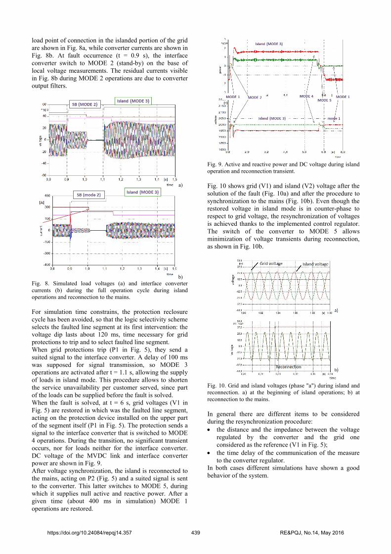
Apart from MODE 2 control, the other five modes are implemented through linear controls. In all these controls, set points for the objective quantities are compared to relevant measured values and the errors are processed by Proportional-Integral regulators, in order to calculate the modulating signals which are sent to a fixed PWM modulator. The two inverters connected in parallel are driven in an interleaved approach, i.e. two different PWM modulators are employed, one for each inverter, using the same modulating signal with two carrier signals in counter-phase, for the generation of switching commands, as reported in Fig. 4.
Fig. 4. Switching commands generation for an interleaved configuration.
https://doi.org/10.24084/repqj14.357 437 RE&PQJ, No.14, May 2016
MODE 2 control is the stand-by condition. In this control mode, all inverter switches are turned off, so that the AC/DC converter exchange null power with the grid.
3. Reverse supply of grid loads When a grid fault occurs along a feeder to which an MVDC interface converter is connected, it is possible to separate part of the feeder from the main and to supply it in island mode from the interface converter itself. The supposed system configuration is represented in Fig. 5.
Fig. 5. System configuration for island supply of loads. At fault occurrence, grid protections trip and then a cycle of automatic reclosures is triggered. When the voltage dip is detected, the MVDC interface converter connected to the faulted feeder is switched from its steady state operation mode, MODE 0 or MODE 1 depending on system configuration, to operation MODE 2 (stand-by), while the other AC/DC converter, at the other end of the DC link, is switched to MODE 1, in order to maintain regulated the DC voltage. It’s worth underlining that in any operation conditions one of the MVDC link converter has to regulate the DC voltage. If the fault is permanent, the final reclosure fails and the protection coordination logic selects the faulted line segment, through a given search procedure. When the faulted line segment has been selected, the protection system, or a central controller, sends to the MVDC interface converter the message to start the reverse supply of the loads through a communication link. The converter switches to MODE 3 control to regulate the AC voltage at the MV output filter to nominal values: line-to-line voltage level 20 kV, frequency 50 Hz. In this phase the converter supplies all loads connected downwards the faulted segment (Fig. 5), if in its power capability. During this phase, interface converter draws active power from the DC link, exploiting possible DG and storage system connected to the DC bus or the other interface converter. After the fault is solved, the faulted line segment is re-connected to the mains (in Fig. 5 P1 closed), and the converter, again in island operating condition, receive the command to turn to MODE 4 control, in which it gradually shifts it regulated output voltage (V2 in Fig. 5) from nominal values to post-fault main grid values (V1 in Fig. 5). This operation mode lasts until island voltage is synchronized to the mains voltage at the separation point. Since this separation point can be far from the connection point of the converter, slight differences between regulated voltage and mains voltage may occurs, depending on feeder length and loading. So, tolerances on voltage, frequency and angle levels should be taken into account. The control scheme for MODE 3 and MODE 4 operating modes is reported in Fig. 6. The only difference from the
two control modes is the calculation of the reference voltage values. In MODE 3 reference voltages are fixed nominal values, while in MODE 4 reference voltages are calculated through and “outer” closed control loop that measures the difference between grid (V1) and island (V2) voltages and processes it through a PI controller.
Fig. 6. Control scheme for MODE 3 and MODE 4 operating conditions. When grid and island voltages are synchronized, within the tolerances, the separation switch (P2 in Fig. 5) is re-closed and the converter is re-connected to the mains. After the reclosure, the MVDC interface converter is switched in MODE 5 operating conditions by some message from the protection system, or from a central controller. In this phase the converter regulates to zero its output active and reactive power. In such a way, the reconnection transient is minimized. The graphical representation of the entire process of island operations and grid reconnection is reported in Fig. 7.
Fig. 7. Finite state machine describing the succession of control MODES for island operations and grid reconnection.
4. Simulation results A simulation model of the 5 MW MVDC link between two AC distribution grid has been developed in the ATPDraw environment. The model comprises the 5 MVA interface converters, each made of two three-phase inverters in interleaved configuration, together with their controls. AC grids are equipped with grid protections implementing logic selectivity and automatic reclosure cycles [5]. Both interface converters are connected at the end of two distribution feeder, one of length 15 km, in the first AC grid (G1), and the other of 5 km, in the other AC grid (G2) (Fig. 5). Grid protections separate the feeder in three line segments. In simulations, a permanent three-phase fault occurs in the second line segment at simulation time t = 0,9 s with a resistive impedance (Fig. 5). Voltages measured at a
https://doi.org/10.24084/repqj14.357 438 RE&PQJ, No.14, May 2016
load point of connection in the islanded portion of the grid are shown in Fig. 8a, while converter currents are shown in Fig. 8b. At fault occurrence (t = 0.9 s), the interface converter switch to MODE 2 (stand-by) on the base of local voltage measurements. The residual currents visible in Fig. 8b during MODE 2 operations are due to converter output filters.
a)
b) Fig. 8. Simulated load voltages (a) and interface converter currents (b) during the full operation cycle during island operations and reconnection to the mains. For simulation time constrains, the protection reclosure cycle has been avoided, so that the logic selectivity scheme selects the faulted line segment at its first intervention: the voltage dip lasts about 120 ms, time necessary for grid protections to trip and to select faulted line segment. When grid protections trip (P1 in Fig. 5), they send a suited signal to the interface converter. A delay of 100 ms was supposed for signal transmission, so MODE 3 operations are activated after t = 1.1 s, allowing the supply of loads in island mode. This procedure allows to shorten the service unavailability per customer served, since part of the loads can be supplied before the fault is solved. When the fault is solved, at t = 6 s, grid voltages (V1 in Fig. 5) are restored in which was the faulted line segment, acting on the protection device installed on the upper part of the segment itself (P1 in Fig. 5). The protection sends a signal to the interface converter that is switched to MODE 4 operations. During the transition, no significant transient occurs, nor for loads neither for the interface converter. DC voltage of the MVDC link and interface converter power are shown in Fig. 9. After voltage synchronization, the island is reconnected to the mains, acting on P2 (Fig. 5) and a suited signal is sent to the converter. This latter switches to MODE 5, during which it supplies null active and reactive power. After a given time (about 400 ms in simulation) MODE 1 operations are restored.
Fig. 9. Active and reactive power and DC voltage during island operation and reconnection transient. Fig. 10 shows grid (V1) and island (V2) voltage after the solution of the fault (Fig. 10a) and after the procedure to synchronization to the mains (Fig. 10b). Even though the restored voltage in island mode is in counter-phase to respect to grid voltage, the resynchronization of voltages is achieved thanks to the implemented control regulator. The switch of the converter to MODE 5 allows minimization of voltage transients during reconnection, as shown in Fig. 10b.
Fig. 10. Grid and island voltages (phase "a") during island and reconnection. a) at the beginning of island operations; b) at reconnection to the mains. In general there are different items to be considered during the resynchronization procedure: the distance and the impedance between the voltage
regulated by the converter and the grid one considered as the reference (V1 in Fig. 5);
the time delay of the communication of the measure to the converter regulator.
In both cases different simulations have shown a good behavior of the system.
https://doi.org/10.24084/repqj14.357 439 RE&PQJ, No.14, May 2016

4. Conclusion The paper presents the design and the modelling of a 5 MW Medium Voltage DC link to mesh two different MV distribution grids. The MVDC link is interfaced to AC grids through AC/DC interface converter, implemented by the connection in parallel of two 2.5 MVA three-phase inverters. The work focuses on the possibility of using the interface converter and the DC link to supply in island mode part of the loads connected to AC grids when a grid fault occurs. This allows reducing the service unavailability time, allowing a fast reverse feeding of “healthy” line segment downwards the faulted segment. A complex control scheme has been designed for managing all the possible operations modes of the converters, including island operations, resynchronization to mains and reconnection. Such a scheme needs some communication links between power converters and grid protection systems, since the interface converter cannot be operated on the base of pure local measurements. Simulations in the ATPDraw environments has shown the effectiveness of this approach, both in terms of reducing the “out of service” duration and of minimization of the voltage transients, in particular during the phase of reconnection to the main grid.
Acknowledgement This work has been financed by the Research Fund for the Italian Electrical System under the Contract Agreement between RSE S.p.A. and the Ministry of Economic Development - General Directorate for Nuclear Energy, Renewable Energy and Energy Efficiency in compliance with the Decree of March 8, 2006.
References [1] Sanjay K. Chaudhary, Josep M. Guerrero, Remus
Teodorescu, “Enhancing the Capacity of the AC Distribution System Using DC Interlinks—A Step Toward Future DC Grid”, IEEE TRANSACTIONS ON SMART GRID 2015
[2] F. Belloni, R. Chiumeo, C. Gandolfi M. Brenna, “Application of Back-to-Back Converters in Closed-Loop and Meshed MV Distribution Grid”, AEIT Annual Conference - From Research to Industry: The Need for a More Effective Technology Transfer (AEIT), 2014
[3] Pracha Khamphakdi, Kei Sekiguchi, Makoto Hagiwara, Hirofumi Akagi, “Design and Experiment of a Back- To-Back (BTB) System Using Modular Multilevel Cascade Converters for Power Distribution Systems”, ECCE Asia Downunder (ECCE Asia), 2013 IEEE.
[4] M. Chiandone, G. Sulligoi, P. Manià, G. Piccoli, “A back-to-back system for power flow control in transnational distribution systems”, AEIT Annual Conference - From Research to Industry: The Need for a More Effective Technology Transfer (AEIT), 2014
[5] F. Belloni, C. Chiumeo, C. Gandolfi, S. Pugliese, “Simulation model of a protection scheme for active distribution networks”, International Conference on Renewable Energies and Power Quality (ICREPQ’13), Bilbao (Spain), 20th to 22th March, 2013
https://doi.org/10.24084/repqj14.357 440 RE&PQJ, No.14, May 2016


