Embed Size (px)
Citation preview

European Association for the Development of Renewable Energies, Environment and Power Quality (EA4EPQ)
International Conference on Renewable Energies and Power Quality
(ICREPQ’10)
Granada (Spain), 23th to 25th March, 2010
Three Phase Grid Connected Photovoltaic System with Active and Reactive Power
Control Using “Instantaneous Reactive Power Theory”
G. Adamidis
1, G. Tsengenes
1 and K. Kelesidis
1
1 Department of Electrical Engineering and Computer Engineering
Democritus University of Thrace, University Campus Kimmeria, 67100 Xanthi (Greece)
E-mail: [email protected], [email protected], [email protected]
Abstract. In this paper, a photovoltaic (P/V) system, with
maximum power point tracking (MPPT), connected to a three
phase grid is presented. The connection of photovoltaic system
on the grid takes place in one stage using voltage source
inverter (VSI). For a better utilization of the photovoltaic
system, the control strategy applied is based on p-q theory.
According to this strategy during sunlight the system sends
active power to the grid and at the same time compensates the
reactive power of the load. In case there is no sunlight (during
the night for instance), the inverter only compensates the
reactive power of the load. The advantage of this strategy is the
operation of the photovoltaic system the whole day. In this
paper the p-q theory is proposed, which does not demand the
use of PLL and introduces simple algebraic calculations.
Key words
Grid-connected PV system, Maximum power point
tracking, Instantaneous reactive power theory, Reactive
power compensation, Power quality.
1. Introduction
Renewable energy sources are a very good solution in the
global energy problem. Over the last decades the grid
integration of renewable energy sources is carried out by
power electronics [1]. The energy generated by
photovoltaic systems constitutes a large part of the total
amount of energy produced by renewable energy sources
[2]. The output power of photovoltaic systems is
significantly affected by weather conditions. Therefore,
extracting maximum power from photovoltaic systems
forms a major part of research activity. Several maximum
power point tracking algorithms for photovoltaic systems
have been developed [3]. These algorithms are applied in
DC/DC converters [4] or in DC/AC inverters.
There have been many research efforts to improve the
efficiency of photovoltaic system. These efforts aimed at
supplying the grid with active and reactive power. In
periods when there is no sunshine, the inverter supplies
the network with reactive power only.
In tasks [5], [6], [7] a control algorithm is proposed based
on synchronous rotating frame (SRF) for the adjustment
of active and reactive power. The control of active and
reactive power is based on the control of currents in the
d-q rotating reference system.
In task [5] a DC\DC converter, two PI controllers and
one PLL are used. However, this increases the cost and
complexity of the system. In exercise [6] a DC-AC
inverter and a PLL controller are used. Yet, the
mathematical model for the control of reactive power is
not clear. To extract reference current, passive filters are
used, which introduce errors in the phase angle and in the
width of the reference current [7].
This paper proposes the use of the theory of
instantaneous reactive power (pq theory) [8] which
controls the active and reactive power in the output of the
inverter. The advantages of using this method are the
absence of PLL and the application of simple algebraic
calculations to raise speed of the system. Connection to
the grid takes place in one stage. Also the method of
incremental conductance (INC) is used to determine the
maximum power point due to the simple mathematical
analysis required [9].
In the remaining sections of this paper the proposed
model of the photovoltaic array and the MPPT is
described and the mathematical model of the inverter is
presented. Finally, the simulation of the proposed system
is carried out and the findings from the investigation are
reported.
2. Description of the proposed system
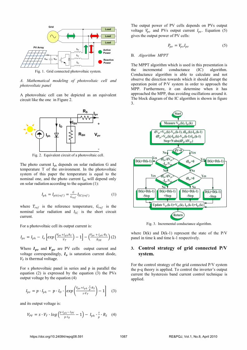
The proposed system is shown in figure 1. For the
analysis of this system the knowledge of mathematical
models reflecting the electrical quantities in the output of
the photovoltaic cell and photovoltaic panel [10] is
required. These models are used by the MPPT algorithm
for calculating the MPP.
https://doi.org/10.24084/repqj08.591 1086 RE&PQJ, Vol.1, No.8, April 2010
Load
Load
Load
Lc
Lc
Lc
VDCCDC
PV Array
Grid
Active
Power
Reactive
Power
Fig. 1. Grid connected photovoltaic system.
A. Mathematical modeling of photovoltaic cell and
photovoltaic panel
A photovoltaic cell can be depicted as an equivalent
circuit like the one in Figure 2.
Iph
ID
RSH
RS
ISH
Ipv
+
-
Vpv
Fig. 2. Equivalent circuit of a photovoltaic cell.
The photo current Iph depends on solar radiation G and
temperature T of the environment. In the photovoltaic
system of this paper the temperature is equal to the
nominal one, and the photo current Iph will depend only
on solar radiation according to the equation (1):
𝐼𝑝 = 𝐼𝑝 𝑟𝑒𝑓 =𝐺
𝐺𝑟𝑒𝑓𝐼𝑆𝐶(𝑟𝑒𝑓 ) (1)
where 𝛵𝑟𝑒𝑓 is the reference temperature, 𝐺𝑟𝑒𝑓 is the
nominal solar radiation and 𝐼𝑆𝐶 is the short circuit
current.
For a photovoltaic cell its output current is:
𝐼𝑝𝑣 = 𝐼𝑝 − 𝐼𝑜 𝑒𝑥𝑝 𝑉𝑝𝑣 +𝐼𝑝𝑅𝑆
𝑉𝑇 − 1 −
𝑉𝑝𝑣 + 𝐼𝑝 ∙𝑅𝑆
𝑅𝑆𝐻 (2)
Where 𝑰𝒑𝒗 and 𝑽𝒑𝒗 are PV cells output current and
voltage correspondingly, 𝑰𝝄 is saturation current diode,
𝑉𝑇 is thermal voltage.
For s photovoltaic panel in series and p in parallel the
equation (2) is expressed by the equation (3) the PVs
output voltage by the equation (4)
𝐼𝑝𝑣 = 𝑝 ∙ 𝐼𝑝 − 𝑝 ∙ 𝐼𝑂 ∙ 𝑒𝑥𝑝 𝑉𝑝𝑣 +𝐼𝑝 ∙
𝑠
𝑝∙𝑅𝑆
𝑠∙𝑉𝑇 − 1 (3)
and its output voltage is:
𝑉𝑃𝑉 = 𝑠 ∙ 𝑉𝑇 ∙ 𝑙𝑜𝑔 𝑝∙𝐼𝑝− 𝐼𝑃𝑉
𝑝∙𝐼𝑂− 1 − 𝐼𝑝 ∙
𝑠
𝑝∙ 𝑅𝑆 (4)
The output power of PV cells depends on PVs output
voltage 𝑉𝑝𝑣 and PVs output current 𝛪𝑝𝑣 . Equation (5)
gives the output power of PV cells:
𝑃𝑝𝑣 = 𝑉𝑝𝑣𝛪𝑝𝑣 (5)
B. Algorithm MPPT
The MPPT algorithm which is used in this presentation is
the incremental conductance (IC) algorithm.
Conductance algorithm is able to calculate and not
observe the direction towards which it should disrupt the
operation point of P/V system in order to approach the
MPP. Furthermore, it can determine when it has
approached the MPP, thus avoiding oscillations around it.
The block diagram of the IC algorithm is shown in figure
3.
Start
Measure Vpv(k), Ipv(k)
dVpv=Vpv(k)-Vpv(k-1), dIpv(k)-Ipv(k-1)
dPpv=Vpv(k)∙Ipv(k)-Vpv(k-1)∙Ipv(k-1)
Step=N∙abs(dPpv/dVpv)
dV=0
dIpv/dVpv=
-Ipv/Vpv
D(k)=D(k-1)
D(k)=D(k-1)
+Step
Update Vpv(k-1)=Vpv(k), Ipv(k-1)=Ipv(k)
Return
D(k)=D(k-1)
-Step
D(k)=D(k-1)
-StepD(k)=D(k-1)
-Step
No
No No
NoNo
Yes
Yes
Yes
Yes
YesdIpv=0
dIpv>0dIpv/dVpv=
-Ipv/Vpv
D(k)=D(k-1)
Fig. 3. Incremental conductance algorithm.
where D(k) and D(k-1) represent the state of the P/V
panel in time k and time k-1 respectively.
3. Control strategy of grid connected P/V
system.
For the control strategy of the grid connected P/V system
the p-q theory is applied. To control the inverter’s output
current the hysteresis band current control technique is
applied.
https://doi.org/10.24084/repqj08.591 1087 RE&PQJ, Vol.1, No.8, April 2010

Lc
Lc
Lc
VDC
CDC
PV ArrayGrid
}
MPPT
Algorithm
IPVVPV
}
+-
VDC,REF
PI
+
Lo
ad
Lo
ad
Lo
ad
PWM
Hysteresis
ica
icb
icc
a,b,c
p,qReactive
Power
iLa
iLb
iLc
usa
usb
usc
pPV -
pLos
pInv qInv
iLα
iLβ
usα
usβ
ic*α ic*β
ic*a ic*b ic*c
α,β
α,β
Fig. 4. Block diagram of the control strategy of P/V system.
The variables, which we measure, are the PV’s output
power 𝑝𝑃𝑉 , the capacitor’s voltage VDC, the mains’
voltages 𝑢𝑠a , 𝑢𝑠𝑏 , 𝑢𝑠𝑐 and the inverter’s output currents
𝑖𝑐a , 𝑖𝑐b , 𝑖𝑐c , which are shown in figure 4. Active and
reactive power control was based on the “instantaneous
reactive power theorem”. Figure 4 shows a block
diagram of control and formation strategy of the
proposed power system.
The advantage of this control method is that it introduces
simple algebraic calculations and does not require the use
of PLL to synchronize the PV system with the grid.
According to the “instantaneous reactive power theorem”
mains voltages and load currents are transformed from
a-b-c coordinates reference system to α-β coordinates
reference system (Clark transformation). This
transformation is shown in Figure 5.
a
b
c
fafb
fc
2π/3
fβ
fα
fref
Fig.5. Transformation from a-b-c into α-β coordinates
system.
The mathematical relations of the load current and mains
voltages in the two different coordinate systems are given
by equations (6) and (7) respectively:
𝑖𝐿,𝛼𝛽 = 𝛭𝑖𝐿,a𝑏𝑐 , 𝑖𝐿,a𝑏𝑐 = 𝛭−1𝑖𝐿,𝛼𝛽 (6)
𝑢𝑠,𝛼𝛽 = 𝛭𝑢𝑠,𝑎𝑏𝑐 , 𝑢𝑠,𝑎𝑏𝑐 = 𝛭−1𝑢𝑠,𝛼𝛽 (7)
Where:
𝑖𝐿,𝛼𝛽 = 𝑖𝐿𝛼 𝑖𝐿𝛽 𝛵 , 𝑢𝑠,𝛼𝛽 = 𝑢𝑠𝛼 𝑢𝑠𝛽 𝛵 ,
𝑖𝐿,𝑎𝑏𝑐 = 𝑖𝐿a 𝑖𝐿𝑏 𝑖𝐿𝑐 𝛵 , 𝑢𝑠,𝑎𝑏𝑐 = 𝑢𝑠a 𝑢𝑠𝑏 𝑢𝑠𝑐 𝛵 ,
𝛭 is the matrix of Clark transformation and equals to:
𝑀 = 2
3 1 −
1
2 −
1
2
0 3
2 −
3
2
, 𝛭−1 = 2
3
1 0
−1
2
3
2
−1
2−
3
2
𝛭−1 = 𝛭𝑇 because matrix M is an orthogonal matrix.
A. Reactive power control
The p-q theory introduces a new variable, which is the
instantaneous imaginary power q and corresponds to the
instantaneous reactive power. The instantaneous reactive
power with which the inverter feeds the load is given
according to the p-q theory by the following equation:
𝑞 = 𝑢𝑠𝛼 𝑖𝐿𝛽 − 𝑢𝑠𝛽 𝑖𝐿𝛼 = −𝑢𝑠𝛽 𝑢𝑠𝛼 𝑖𝐿𝛼𝑖𝐿𝛽
(8)
B. Active power control
Figure 9 shows the block diagram of active power control
for the proposed photovoltaic system.
Kp +Ki/SVDC
VDC,REF
pLosΔV+
-+
-pPV
pInv
Fig. 6. Block diagram of inverter’s active power control.
The MPPT algorithm gives the maximum power point,
and hence the maximum power 𝑝𝑃𝑉 of photovoltaic
panel for a given radiation. Due to the switching
operation of the voltage source inverter, some losses are
caused in the circuit 𝑝𝐿𝑜𝑠 . According to the block
diagram of Figure 6, the losses are covered by the solar
https://doi.org/10.24084/repqj08.591 1088 RE&PQJ, Vol.1, No.8, April 2010

energy when P/V system operates and supplies the grid
with active power. During the period in which the
photovoltaic system does not produce active power, then
the losses 𝑝𝐿𝑜𝑠 are covered by the inverter from the grid.
C. Reference Current Generation
The p-q theory based on instantaneous active and reactive
power, calculates the reference currents in α-β system
according to the equation (9):
𝑖𝑐 ,𝛼∗
𝑖𝑐 ,𝛽∗ =
1
us ,α2 +us ,β
2 ∙ us,α us,β
us,β −us,α
−pPV + −pLos
−𝑞 (9)
Using the inverse transformation of equation (6) we
calculate the reference currents in the a-b-c coordinates
system according to the following equation:
𝑖𝑐 ,𝑎∗
𝑖𝑐 ,𝑏∗
𝑖𝑐 ,𝑐∗
= 2
3
1 0
−1
2
3
2
−1
2−
3
2
𝑖𝑐 ,𝛼∗
𝑖𝑐 ,𝛽∗ (10)
D. Current Control
For the control of the output current of the inverter we
will apply the hysteresis band current control technique,
which is shown in figure 7 [11]. With this method we
create a zone around the reference current trying to keep
the inverter’s output current within this zone. The
advantages of hysteresis band control technique are its
simple application, its very good dynamic behaviour and
its fast response.
Σ
+H/2
-H/2
error DC/ AC
Inverter
ic
+-
gating
signalIc*
Fig. 7. Block diagram of hysteresis band current control
technique.
The hysteresis band current control defines the timing
and duration of each pulse. The switching logic for phase
“a” is summarized as follows:
● If the inverter’s output current reaches the zone’s upper
limit then the upper switch is OFF and the lower switch
is ON.
● If the inverter’s output current reaches the zone’s lower
limit then the upper switch is ON and the lower switch is
OFF.
The switching functions for phases “b” and “c” are
determined similarly.
4. Simulation Results
We will simulate the proposed electrical power system of
chapter 2. For the system’s control we will apply the p-q
theory. Figure 8.a shows the changes in solar radiation at
specific times. It was felt that changes in solar radiation
were instantaneous. Figure 8.b shows the corresponding
modifications of the active power in both grid Pgrid and
photovoltaic Ppv to meet the real load power Pl. The
sudden changes of Pl were due to sudden changes of Ppv.
In a real system changes in Ppv are much slower;
therefore changes in Pl are much smoother. Also in
Figure 8.c we observe the reactive power of the grid
Qgrid.B without the P/V system and the reactive power of
the Qgrid.B using the P/V system which acts as a reactive
power compensator.
a)
b)
c)
Fig. 8. a) Solar radiation, b) active power of the grid, P/V
system and load c) reactive power of the grid with and without
the P/V system.
In this paper the behavior of the system for radiation
500𝑤
𝑚2 is investigated. Figure 9.a illustrates the phase a
currents of the load iLa, the inverter ica, and the grid isa.
From figure 9.a it is obvious that the load current is the
sum of the inverter’s current and the grid current. Figure
9.b shows active power of the load, of the grid and the
P/V system. The grid and the P/V system meet the
requirements of the load.
https://doi.org/10.24084/repqj08.591 1089 RE&PQJ, Vol.1, No.8, April 2010

a)
b)
Fig. 9. a) the phase a currents of the load iLa, of the inverter ica
and the grid isa, b) active power of the load, of the P/V system
and the grid.
Figure 10.a depicts the waveforms of phase a currents for
the load iLa, the inverter ica, and the grid isa in a transition,
that is when the solar radiation is altered from 500𝑤
𝑚2 to
750𝑤
𝑚2. Figure 10.b shows the corresponding changes in
real power of the load Pl, of the grid Pgrid and of the P/V
system Ppv. A similar change exists in the current and the
power when solar radiation is reduced.
a)
b)
Fig. 10. a) the phase a currents of the load iLa, the inverter ica,
and the grid isa, b) active power of the load, of the P/V system
and the grid.
Figure 11 shows the transition when radiation becomes
zero and the P/V system compensates only the reactive
power of the load. Figure 11.a shows that the grid
current increases while the current of the photovoltaic
system is reduced. Figure 11.b shows the corresponding
changes in real power of the load Pl, of the grid Pgrid and
the F/V system Ppv. From a series of simulations on this
operational state, it appears that the grid current is equal
to the real load current, while the P/V system current is
equal to the reactive load current.
a)
b)
Fig. 11. a) the phase a currents of the load iLa, the inverter ica,
and the grid isa, b) active power of the load, of the P/V system
and the grid.
The facts of the photovoltaic system and the grid which
were simulated are given in table Ι and table ΙΙ
respectively.
Table Ι. – Parameters of P/V array.
DESCRIPTION PARAMETER
Number of parallel P/V panel 2
Number of P/V panel in series 40
Open circuit voltage 20.1 V
Short circuit current 3.45A
Reference solar radiation 1000w/m2
Reference temperature 24oc
Saturation diode current 4.05e-7 A
Table ΙI. – Parameters of electrical power system.
DESCRIPTION PARAMETER
Inductive Coupling LC = 30.7 mH
DC Bus Capacitor CDC = 1.3 mF
Load RL= 10 Ω , LL=20mΗ
Grid |VS| = 230V
Frequency f = 50Hz
Induction of grid LS = 0.15mH
https://doi.org/10.24084/repqj08.591 1090 RE&PQJ, Vol.1, No.8, April 2010

5. Conclusion
To increase the efficiency of photovoltaic systems in
recent years their use has been studied in order to
compensate reactive power. In this paper a simple and
effective control method is proposed using the p-q theory
so as the photovoltaic system to compensate the reactive
power of the load throughout the day. In fact, the
application of such a photovoltaic system in the
household and in industry in order to compensate reactive
power at night or other times of day when there is no
sunshine, would greatly improve the power factor of the
installation.
Future prospects of the present proposal include a more
realistic modeling of photovoltaic cells and the
modification of the control method so that the system
works, even if the source voltage is not ideal and the load
current contains harmonic components.
References [1] F. Iov, M. Ciobotaru, D. Sera, R. Teodorescu and
F.Blaabjerg, “Power Electronics and Control of
Renewable Energy Systems”, PEMD 2007, Bangkok, pp.
6-28.
[2] Mohamed A. Eltawil, Zhengming Zhao, “Grid -
connected photovoltaic power systems: Technical and
potential problems-A review”, ELSEVIER Renewable
and Sustainable Energy Reviews 14 (2010), pp. 112-
129.
[3] Roberto Faranda, Sonia Leva, “Energy comparison of
MPPT techniques for PV Systems”, WESAS
TRANSACTION on POWER SYSTEMS, Issue 6,
Volume 3, June 2008.
[4] Peftitsis D., Adamidis G., Bakas P., Balouktsis A.,
“Photovoltaic system MPPTracker investigation and
implementation using DSP engine and buck – boost DC-
DC converter” EPE-PEMC 2008.
[5] Huajum Yu, Junmin Pan, An Xiang, “A multi-function
grid-connected PV system with reactive power
compensation for the grid”, ELSEVIER Solar Energy 79
(2005) 101-106.
[6] M.B. Bana Sharifian, Y. Mohamadrezapour, M.
Hosseinpour and S. Torabzade, “Single-Stage Grid
Connected Photovoltaic System with Reactive Power
Control and Adaptive Predictive Current Controller”,
Journal of Applied Sciences, 2009 ISSN 1812-5654.
[7] Mateus F. Schonardie and Deniraz C. Martins, “Three-
Phase Grid Connected Photovoltaic System With Active
And Reactive Power Control Using dq0 Transformation”,
PESC 2008 Rhodes, pp. 1202-1207.
[8] Lazek S. Czarnecki, “Instantaneous Reactive Power p-q
Theory and Power Properties of Three-Phase Systems”,
IEEE Transactions on Power Delivery Vol. 21 No. 1,
January 2006.
[9] Fangrui Liu, Shanxu Duan, Fei Liu, Bangyin Liu and Yong
Kang, “An Variable Step Size INC MPPT Method for PV
Systems”, IEEE Transactions on Industrial Electronics,
Vol. 55, No. 7, July 2008.
[10] Tomas Skocil, Manuel Perez Donsion, “Mathematical
Modeling and Simulation of Photovoltaic Array”,
ICREPQ 2008.
[11] Marian P. Kazmierkowski, Luigi malesani, “Current
Control Techniques for Three-Phase Voltage-Sourece
PWM Converters: A Survey, IEEE Transactions on
Industrial Electronics Vol. 45 No. 5, October 1998.
https://doi.org/10.24084/repqj08.591 1091 RE&PQJ, Vol.1, No.8, April 2010

![Design of Grid-Connected Photovoltaic System · weight of photovoltaic system [7]. The grid[6] -connected photovoltaic systems also need the inverters for power conversion, grid interconnection](https://img.dokumen.tips/doc/110x75/5fba0adb999fbb3bbe303c6e/design-of-grid-connected-photovoltaic-system-weight-of-photovoltaic-system-7.jpg)
![Storage Size Determination for Grid-Connected Photovoltaic ... · PDF filearXiv:1109.4102v2 [math.OC] 10 Jan 2012 1 Storage Size Determination for Grid-Connected Photovoltaic Systems](https://img.dokumen.tips/doc/110x75/5a78acdd7f8b9ab8768e9464/storage-size-determination-for-grid-connected-photovoltaic-11094102v2-mathoc.jpg)