Embed Size (px)
Citation preview

BCT 120 Floor Framing
SILL PLATE INSTALLATION

After the Foundation Check points are addressed
• Spread the sill material around the foundation perimeter. Check that the lengths will work so splices will have end bolts
and each piece will have a minimum of two bolts.
• Set the sill on the top of the wall outside of the bolts and square
each bolt side.
• Measure from outside stem wall to bolt center and mark this dimension on the sill.
• Bore 9/16" holes for the bolts.
• Install sill sealer material and place the sill material.
• Install washer and nut
• Check outside dimensions and diagonals.
• Set up a level and shoot all corners. If they are not all the same elevation, start with the highest and adjust the others so they all
are equal.

Anchor Bolt

Tapping the Plate for Bolt Location
• If you have worked with a framing crew you have probably noticed experienced framers mark the sill bolts by holding the sill in location on top of the bolts and striking the top of the sill causing an indent.
• This is difficult to do accurately, takes practice to develop the skill and requires a perfectly straight and dimension foundation wall with bolts all set at the same height.
• This method is done to save time but requires the conditions listed above to achieve success.

Sill Plates Installation• After initial sill installation, adjust all corners to level
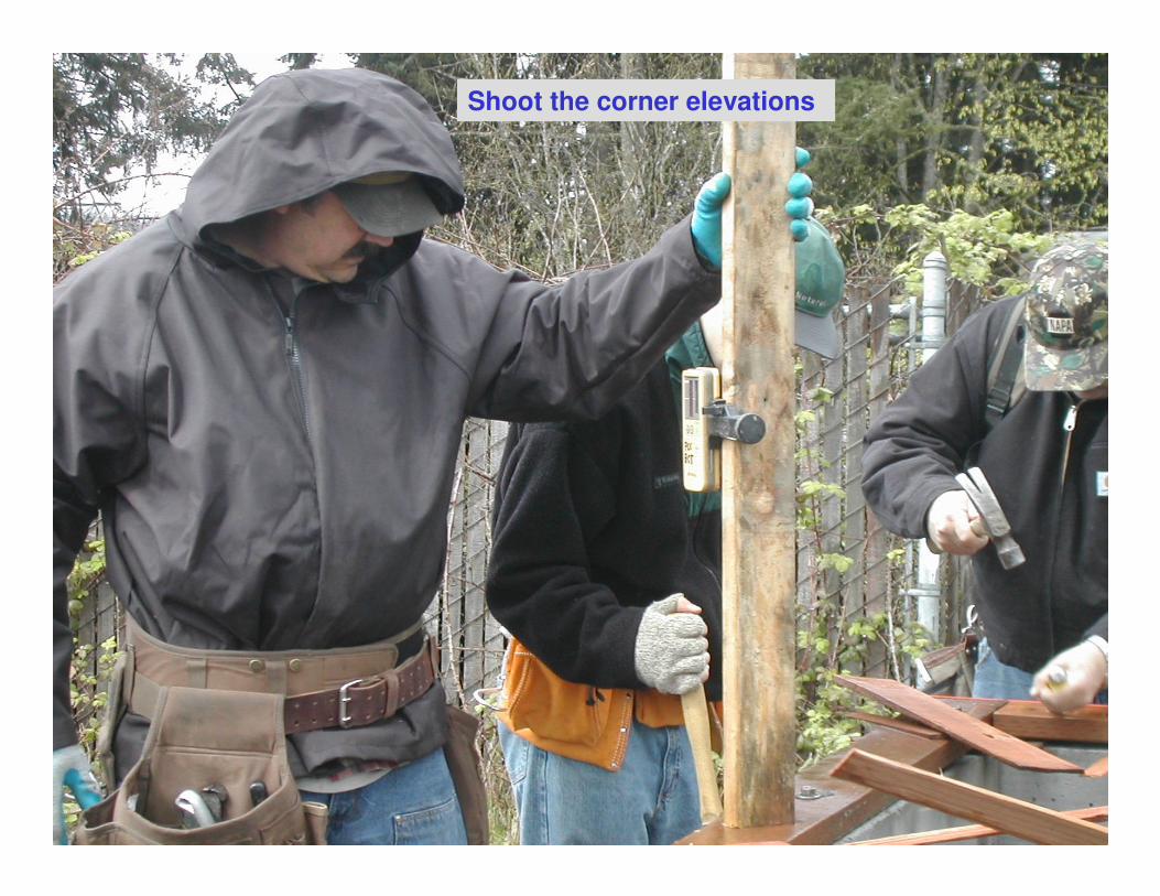
then stretch a string line from corner to corner.
• Shim the sill plates between corners where necessary
to level and adjust in or out to straight.
• Important to verify outside dimensions.
• A good foundation will require very few adjustments.
• Lay-out the sill plate beam pockets @ 4ft. outside to
center and confirm that they match the foundation.
• Most important is the sill plate notch be cut exact to
the beam width and proper depth so ½" of air space is
provided on each side and beam end.

Review string line check


To achieve a straight sill plate the plate may not flush with the stem wall
Shoot the corner elevations

Shim the corners so all are equal elevations
Stretch a tight dry string line corner to corner and adjust sill if necessary
Lay-out beam pockets from outside wall to 48" O/C

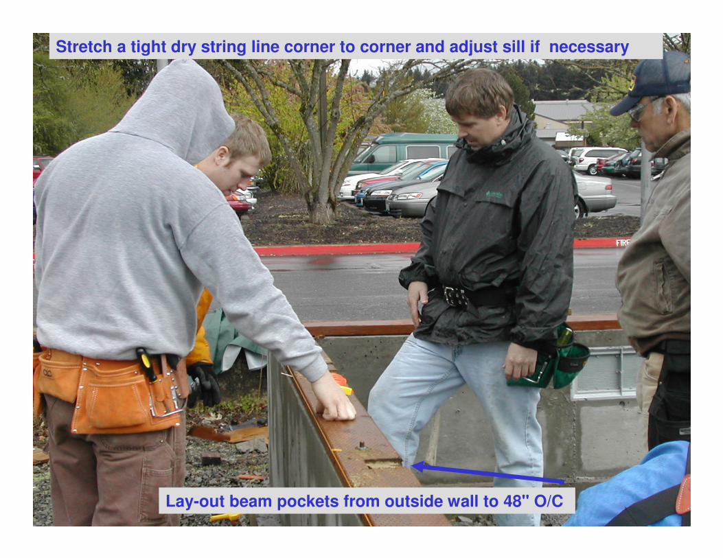
Beam PocketsSill plate must be notched to allow ½" air space

Concrete Beam Pocket Adjustment • The beam needs to rest on a piece of asphalt
comp roofing or other approved barrier.
• The top of the beam needs to be flush with the top of the sill plate.
• To achieve this additional pieces of comp roofing or P.T shims may need to be added. In worst case the pocket may not be deep enough and some of the beam pocket may need to be chipped out with a cold chisel.

Beam Pocket Detail

Tight fit & flush to top of sill plate

Post & Beam Project Plan
90º corners


![BLIND VALLEY ROOFspot.pcc.edu/~rsteele/bct_102/blind_valley.pdf · 2008-06-03 · Microsoft PowerPoint - blind_valley.ppt [Compatibility Mode] Author: scitech Created Date: 6/2/2008](https://img.dokumen.tips/doc/110x75/5f0a8f1f7e708231d42c3a24/blind-valley-rsteelebct102blindvalleypdf-2008-06-03-microsoft-powerpoint.jpg)