Embed Size (px)
Citation preview
OPERATION MANUALShunt Unit
Part No. Z1-000-072, IB000024
Nov. 2005
SH10SH50

Use of Operation Manual
• Please read through and understand this Operation Manual before operating the product. After reading, always keep themanual nearby so that you may refer to it as needed. When moving the product to another location, be sure to bring themanual as well.
• If you find any incorrectly arranged or missing pages in this manual, they will be replaced. If the manual gets lost orsoiled, a new Operation Manual can be purchased. In either case, please contact your Kikusui agent, and provide the"Part No." given on cover.
• This manual has been prepared with the utmost care; however, if you have any questions, or note any errors or omissions,please contact your Kikusui agent.
The contents of this Operation Manual may not be reproduced, in whole or in part, without the prior consent of thecopyright holder.The specifications of this product and the contents of this Operation Manual are subject to change without priornotice.
Copyright© 1999-2005 Kikusui Electronics Corporation


SH Series Setup 1-1
Chapter 1 Setup
This chapter presents procedures for setup, ranging from unpacking to starting theunit.
1.1 Checks at UnpackingUpon receiving this product, make sure the package contains the necessaryaccessories and has not been damaged during transportation. If any part is damagedor missing, contact Kikusui distributor/agent.
INPUT terminal cover �(For the SH10, �the cover is already �installed.)
Flat cable for �connection
AC power cord
Check pins
Shunt unit�
Operation Manual
Fig. 1-1 Packing/Unpacking
○ ○ ○ ○ ○ ○ ○ ○ ○ ○ ○ ○ ○ ○ ○ ○ ○ ○ ○ ○ ○ ○ ○ ○ ○ ○ ○ ○ ○ ○ ○ ○ ○ ○ ○ ○ ○ ○ ○ ○ ○ ○ ○ ○ ○ ○ ○
NOTE • Packing materials may be used for transport of the product, so it is recommendedthat they be retained.
○ ○ ○ ○ ○ ○ ○ ○ ○ ○ ○ ○ ○ ○ ○ ○ ○ ○ ○ ○ ○ ○ ○ ○ ○ ○ ○ ○ ○ ○ ○ ○ ○ ○ ○ ○ ○ ○ ○ ○ ○ ○ ○ ○ ○ ○ ○

1-2 Setup SH Series
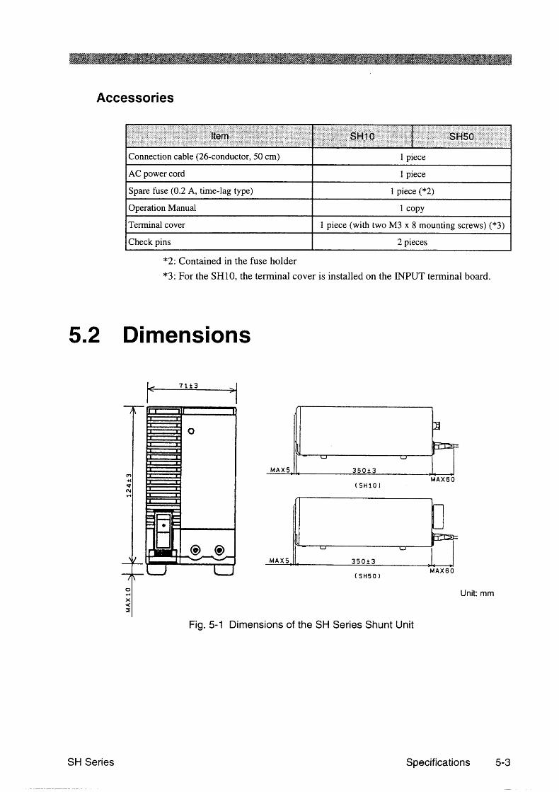
Connection cable AC power cord
Check pins
INPUT terminal cover (with two M3 x 8 mounting screws)For the SH10, the cover is installed on the INPUT terminal board.
Operation manual
FuseThis is provided as a reserve in the fuse holder.
1 piece[99-02-0009]
1 copy[Z1-000-072]
2 pieces[M3-000-081]
1 piece[Q5-000-101]
2 pieces[87-12-0000]
1 piece[83-22-6050]
1 piece[85-AA-0004]
Different types of power cords are provided, depending on the settings of the line voltage range at the time of delivery. This power cord is for voltage of up to 125 V.
Fig. 1-2 List of Accessories

SH Series Setup 1-3
1.2 Precautions for InstallationBe sure to observe the following precautions when installing the unit.
■ Do not use the unit in a flammable atmosphere.
To prevent explosion or fire, do not use the unit near alcohol, thinner, or othercombustible materials, or in an atmosphere containing such vapors.
■ Avoid locations where the unit is exposed to hightemperatures or direct sunlight.
Do not locate the unit near a heater or in areas subject to drastic temperature changes.
Operating temperature range: 0°C to 40°C
■ Avoid humid environments.
Do not locate the unit in a high-humidity environment—near a boiler, humidifier, orwater supply.
Operating humidity range: 10% to 90% R.H
(no dew condensation is allowed)
Condensation may occur even within the operating humidity range. In that case, donot start using the unit until the location is completely dry.
■ Do not place the unit in a corrosive atmosphere.
Do not install the unit in a corrosive atmosphere or one containing sulfuric acid mistor the like. This may cause corrosion of various conductors and imperfect contactwith connectors, leading to malfunction and failure, or in the worst case, a fire.
■ Do not locate the unit in a dusty environment.
Dirt and dust in the unit may cause electrical shock or fire.
■ Do not use the unit where ventilation is poor.
Provide sufficient space around the unit. Otherwise, heat may accumulate in the unit,resulting in fire.
■ Do not place any object on the unit.
Particularly a heavy one, as doing so could result in a malfunction.
■ Do not place the unit on a tilted surface or in a locationsubject to vibrations.
If placed on a non-level surface or in a location subject to vibration, the unit may fall,resulting in damage and injury.
■ Do not use the unit in locations affected by strong magneticor electric fields.
Operation in a location subject to magnetic or electric fields may cause the unit tomalfunction, resulting in electrical shock or fire.

1-4 Setup SH Series
1.3 Precautions for MovingWhen moving or transporting the unit to an installation site, observe the followingprecautions.
■ Turn the POWER switch off.
Moving the unit with the power on may result in electrical shock or damage.
■ Remove all wirings connected.
Moving the unit with cables connected may break the cables or cause the unit to fall,resulting in injury.
■ For transportation, use the special packing material for the unit.
Transport the unit in its original package to prevent vibration and falls, which maydamage the unit. If you require packing material, contact Kikusui distributor/agent.
1.4 Checking Input Power and the FuseAs shown in Fig. 1-3, four line voltage ranges are available for the unit. Check thedefault settings to determine whether the voltage is suitable for your unit. Use a inputpower fuse appropriate for your line voltage range.
WARNING • To prevent electric shock, be sure to unplug the AC power cord or turn theswitch on the switchboard off before checking or replacing the fuse.
CAUTION • Make sure that the fuse used conforms to the unit specifications, includingshape, rating, and characteristics. Using a fuse with different rating orshort-circuiting, the fuse holder will damage the unit.

SH Series Setup 1-5
When checking or changing the line voltage range, or when checking or replacing thepower fuse, observe the following instructions:
1. – Turn the POWER switch off.
2. – Unplug the AC power cord from the unit.
3. – Check the input voltage range switch at the bottom of the unit to determinewhether it is set at an appropriate voltage for the unit.
To change the setting, follow the instructions on the SWITCH POSITIONindicator. (Fig. 1-3)
4. – Remove the cover from the fuse holder. (Fig. 1-4)
5. – Check the fuse to make sure its rated voltage is within the line voltage range,and that its pre-arcing time-current characteristic is of the time-delay type.
If necessary, replace with an appropriate fuse.
6. – Reset the cover of the fuse holder.
VOLTAGE SELECT SWITCH POSITION FUSE
195V~254V170V~230V98V~132V85V~115V A
AB D
C
B C DA B C D
A B C DA B C D
0.2A SB
AC 50/60Hz MAX 11VA
Fig. 1-3 Input Voltage Range Selector Switches on the Bottom Panel.The figure shows that a range of 85 V to 115 V has been selected.
Fig. 1-4 Removing the Fuse Holder

1-6 Setup SH Series
1.5 AC Power Cord Connection
WARNING • If this unit includes an AC power cord with a three-prong plug as shown inFig. 1-5, carefully check the line voltage range. This type of power cordcannot be used for over 125 VAC. If you use the unit with line voltage over125 VAC, replace with an appropriate power cord compatible with thevoltage to be used.
Do not use this type of power �cord for over 125 VAC.
Fig. 1-5 AC Power Cord with a Three-prong Plug included with the unit
Make connections as follows:
1. – Turn the POWER switch off.
2. – Connect the AC power cord to the AC power connector on the rear panel.
3. – Plug the power cord into the receptacle.
■ To directly connect to the switchboard:
If the AC power cord is to be connected directly to the switchboard without using aplug, install crimp terminals on the power cord.
WARNING • An AC power cord with a 3-prong plug as shown in Fig. 1-5 cannot be usedfor a voltage of over 125 VAC, even if its plug is cut off to be replaced withcrimp terminals.
• To prevent electrical shock, turn off the switchboard before connecting thepower cord.
• Connections to the switchboard must be made by qualified personnel.

SH Series Setup 1-7
1.6 Grounding
WARNING • Not grounding the unit creates danger of electric shock.
• Connect the ground terminal to an electrical ground (safety ground).
CAUTION • Not performing adequate grounding work on the unit results in malfunctionor the production of large noises from the unit.
To ensure safety, provide secure grounding.
The unit can be grounded by one of the two methods specified below. Select one, andground the unit securely.
1. Plug the AC power cord into a 3-pole poweroutlet upon which grounding construction hasbeen performed.
2. Connect terminal on the unit rear panel to theground terminal (GND).
Fig. 1-6 Grounding
To 3-pole power outlet upon which grounding construction has been performed
To the ground terminal (GND) on switchboards

1-8 Setup SH Series
1.7 Setting the Monitor RangeSelection Switch
The range monitor selector switch on the rear panel must be set to “H”, “M,” or “L,”depending on the regulated DC power supply to be connected to the unit. On thesetting ranges for regulated DC power supplies, see “List of Applicable Shunt Unitsby Power Supply” in the Appendix.
Monitor range �selection switch
Fig. 1-7 Monitor Range Selection Switch on the Rear Panel
○ ○ ○ ○ ○ ○ ○ ○ ○ ○ ○ ○ ○ ○ ○ ○ ○ ○ ○ ○ ○ ○ ○ ○ ○ ○ ○ ○ ○ ○ ○ ○ ○ ○ ○ ○ ○ ○ ○ ○ ○ ○ ○ ○ ○ ○ ○
DESCRIPTION • The current to be measured that is input to the INPUT terminals is amplified bythe differential amplifier, output to the J2 connector, and then transmitted to thePIA series. The shunt unit allows you to adjust sensitivity using the range monitorselector switch, so that a wide range of currents can be measured.
○ ○ ○ ○ ○ ○ ○ ○ ○ ○ ○ ○ ○ ○ ○ ○ ○ ○ ○ ○ ○ ○ ○ ○ ○ ○ ○ ○ ○ ○ ○ ○ ○ ○ ○ ○ ○ ○ ○ ○ ○ ○ ○ ○ ○ ○ ○
J2
J1
FROM PIA
FROM PS
(Output for monitoring)
Monitor range selection switch
Differential �amplifier
Detected �resistor
+
+
INPUT
-
-
CURRENT
CHECK
Fig. 1-8 Internal Make-up of SH Series Devices

SH Series Setup 1-9
1.8 Rack Mounting
For installing the unit together with the PAK-A, PAK-AM or PMC-Aseries on a rack
■ Rack adapters
KRA3 (EIA-compatible rack) KRA150 (JIS-compatible rack)
KBP3-6Shunt unit
KBP3-6Shunt unit
132.
557
37.7
5
460482 260
340
149
100
24.5
460480260 340
Unit: mm
Fig. 1-9 Rack AdaptersThis figure shows a configuration where the shunt unit has beeninstalled.
■ Blank panels
KBP3-6�(1/6)
KBP3-3�(1/3)
KBP3-4�(1/4)
KBP3-2�(1/2)
Fig. 1-10 Blank PanelsThese panels are dedicated for KRA3 or KRA150.
The detailed information is indicated on rack adapters.
1-10 Setup SH Series
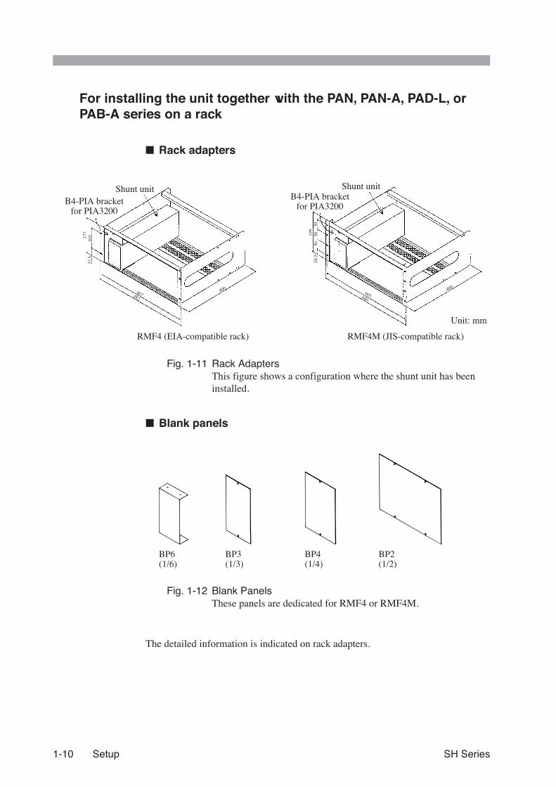
For installing the unit together with the PAN, PAN-A, PAD-L, orPAB-A series on a rack
■ Rack adapters
RMF4 (EIA-compatible rack) RMF4M (JIS-compatible rack)
Shunt unitB4-PIA bracket�
for PIA3200
B4-PIA bracket�for PIA3200
Shunt unit
177
102
37.5
467482
400
199
5050
5024
.5
465480
400
Unit: mm
Fig. 1-11 Rack AdaptersThis figure shows a configuration where the shunt unit has beeninstalled.
■ Blank panels
BP6�(1/6)
BP3�(1/3)
BP4�(1/4)
BP2�(1/2)
Fig. 1-12 Blank PanelsThese panels are dedicated for RMF4 or RMF4M.
The detailed information is indicated on rack adapters.


SH Series Appendix A-1
Appendix
List of Applicable Shunt Units by Power Supply
Table A-1 Applicable Shunt Units for the PAK-A and PAK-AM Series
ID Number Model Applicable unit (*1) Monitor range (*2)
001 PAK6-60A/AM / /
002 PAK6-120A/AM / /
003 PAK6-160A/AM / /
004 PAK10-35A/AM SH50 M
005 PAK10-70A/AM / /
006 PAK10-100A/AM / /
007 PAK20-18A/AM SH50 L
008 PAK20-36A/AM SH50 M
009 PAK20-50A/AM SH50 H
010 PAK35-10A/AM SH10 H
011 PAK35-20A/AM SH50 L
012 PAK35-30A/AM SH50 M
013 PAK60-6A/AM SH10 M
014 PAK60-12A/AM / /
015 PAK60-18A/AM SH50 L
*1: Shunt units indicated by “/” are handled by special order.
*2: Letters indicate the positions of the monitor range selection switch on the rearpanel.

A-2 Appendix SH Series
Table A-2 Applicable Shunt Units for the PAB-A Series(Connectable to only the PIA3200)
ID Number Model Applicable unit (*1) Monitor range (*2)
016 PAB18-1A / /
017 PAB18-1.8A / /
018 PAB18-3A SH10 L
019 PAB32-1.2A / /
020 PAB32-2A / /
021 PAB70-1A / /
022 PAB110-0.6A / /
023 PAB250-0.25A / /
024 PAB350-0.1A / /
Table A-3a Applicable Shunt Units for the PAD-L Series
ID Number Model Applicable unit (*1) Monitor range (*2)
026 PAD8-20L/LP SH50 L
027 PAD8-30L/LP SH50 M
028 PAD8-50L/LP SH50 H
029 PAD8-100L / /
030 PAD16-10L/LP SH10 H
031 PAD16-18L/LP SH50 L
032 PAD16-30L/LP SH50 M
033 PAD16-50L SH50 H
034 PAD16-100L/LP / /
035 PAD16-200L / /
036 PAD16-500L / /
037 PAD35-5L/LC SH10 L
038 PAD35-10L/LP SH10 H
039 PAD35-20L/LP SH50 L
040 PAD35-30L/LP SH50 M
041 PAD35-50L/LP SH50 H
042 PAD35-60L/LP / /
043 PAD35-100L/LP / /
044 PAD35-200L/LP / /
045 PAD35-300LPT / /

SH Series Appendix A-3
Table A-3b Applicable Shunt Units for the PAD-L Series (Continued)
ID Number Model Applicable unit (*1) Monitor range (*2)
046 PAD55-3L SH10 L
047 PAD55-6L SH10 M
048 PAD55-10L SH10 H
049 PAD55-20L SH50 L
050 PAD55-35L SH50 M
051 PAD55-60L / /
052 PAD55-120L / /
053 PAD60-200LPT / /
054 PAD70-2.5L SH10 L
055 PAD70-5L SH10 L
056 PAD70-8L SH10 H
057 PAD70-15L SH50 L
058 PAD110-1.5L / /
059 PAD110-3L SH10 L
060 PAD110-5L SH10 L
061 PAD110-10L SH10 H
062 PAD110-20L SH50 L
063 PAD110-30L SH50 M
064 PAD110-60L / /
065 PAD160-1L / /
066 PAD160-2L / /
067 PAD160-3.5L SH10 L
068 PAD160-7L SH10 M
069 PAD250-2.5L SH10 L
070 PAD250-4.5L SH10 L
071 PAD250-8L SH10 H
072 PAD250-15L SH50 L
073 PAD500-2L / /
*1: Shunt units indicated by “/” are handled by special order.
*2: Letters indicate the positions of the monitor range selection switch on the rearpanel.

A-4 Appendix SH Series
Table A-4 Applicable Shunt Units for the PAE Series(Connectable to only the PIA3200)
ID Number Model Applicable unit (*1) Monitor range (*2)
075 PAE35-10 SH10 H
076 PAE35-20 SH50 L
077 PAE35-30 SH50 M
Table A-5 Applicable Shunt Units for the PMC-A Series
ID Number Model Applicable unit (*1) Monitor range (*2)
080 PMC18-1A / /
081 PMC18-2A / /
082 PMC18-3A SH10 L
083 PMC18-5A SH10 L
084 PMC35-0.5A / /
085 PMC35-1A / /
086 PMC35-2A / /
087 PMC35-3A SH10 L
088 PMC70-1A / /
089 PMC110-0.6A / /
090 PMC160-0.4A / /
091 PMC250-0.25A / /
092 PMC350-0.2A / /
093 PMC500-0.1A / /
*1: Shunt units indicated by “/” are handled by special order.
*2: Letters indicate the positions of the monitor range selection switch on the rearpanel.

SH Series Appendix A-5
Table A-6 Applicable Shunt Units for the PAN and PAN-A Series
ID Number Model (*3) Applicable unit (*1) Monitor range (*2)
094 PAN16-10 (A) SH10 H
095 PAN16-18 (A) SH50 L
096 PAN16-30 (A) SH50 M
097 PAN16-50 (A) SH50 H
098 PAN35-5 (A) SH10 M
099 PAN35-10 (A) SH10 H
100 PAN35-20 (A) SH50 L
101 PAN35-30 (A) SH50 M
102 PAN55-3 (A) SH10 L
103 PAN55-6 (A) SH10 M
104 PAN55-10 (A) SH10 H
105 PAN55-20 (A) SH50 L
106 PAN70-2.5 (A) SH10 L
107 PAN70-5 (A) SH10 L
108 PAN70-8 (A) SH10 H
109 PAN70-15 (A) SH50 L
110 PAN110-1.5 (A) / /
111 PAN110-3 (A) SH10 L
112 PAN110-5 (A) SH10 L
113 PAN110-10 (A) SH10 H
114 PAN160-1 (A) / /
115 PAN160-2 (A) / /
116 PAN160-3.5 (A) SH10 L
117 PAN160-7 (A) SH10 M
118 PAN250-2.5 (A) SH10 L
119 PAN250-4.5 (A) SH10 L
*1: Shunt units indicated by “/” are handled by special order.
*2: Letters indicate the positions of the monitor range selection switch on the rearpanel.
*3: When the PAN-A series is controlled with the PIA3200, the controller returnsthe ID and model of the PAN series for the query message of "ID?."

SH
UN
T U
NIT
SH
10/SH
50O
PE
RA
TIO
N M
AN
UA
L