Embed Size (px)
Citation preview
SFTOS Configuration Guide
Version 2.5.3.0 August 2008 Edition

Copyright 2008 Force10 NetworksAll rights reserved. Printed in the USA. August 2008.Force10 Networks® reserves the right to change, modify, revise this publication without notice. TrademarksForce10 Networks® and E-Series® are registered trademarks of Force10 Networks, Inc. Force10, the Force10 logo, E1200, E600, E600i, E300, EtherScale, TeraScale, FTOS, and SFTOS are trademarks of Force10 Networks, Inc. All other brand and product names are registered trademarks or trademarks of their respective holders.Statement of ConditionsIn the interest of improving internal design, operational function, and/or reliability, Force10 Networks reserves the right to make changes to products described in this document without notice. Force10 Networks does not assume any liability that may occur due to the use or application of the product(s) described herein.USA Federal Communications Commission (FCC) StatementThis equipment has been tested and found to comply with the limits for a Class A digital device, pursuant to Part 15 of the FCC rules. These limits are designated to provide reasonable protection against harmful interference when the equipment is operated in a commercial environment. This equipment generates, uses, and can radiate radio frequency energy. If it is not installed and used in accordance to the instructions, it may cause harmful interference to radio communications. Operation of this equipment in a residential area is likely to cause harmful interference, in which case users will be required to take whatever measures necessary to correct the interference at their own expense.Properly shielded and grounded cables and connectors must be used in order to meet FCC emission limits. Force10 Networks is not responsible for any radio or television interference caused by using other than recommended cables and connectors or by unauthorized changes or modifications in the equipment. Unauthorized changes or modification could void the user’s authority to operate the equipment.This device complies with Part 15 of the FCC Rules. Operation is subject to the following two conditions: (1) this device may not cause harmful interference, and (2) this device must accept any interference received, including interference that may cause undesired operation.Canadian Department of Communication StatementThe digital apparatus does not exceed the Class A limits for radio noise emissions from digital apparatus set out in the Radio Interference Regulations of the Canadian Department of Communications. Attention: Le present appareil numerique n’ emet pas de perturbations radioelectriques depassant les normes applicables aux appareils numeriques de la Class A prescrites dans le Reglement sur les interferences radioelectriques etabli par le ministere des Communications du Canada. European Union EMC Directive Conformance StatementThis product is in conformity with the protection requirements of EU Council Directive 89/336/EEC on the approximation of the laws of the Member States relating to electromagnetic compatibility. Force 10 Networks can not accept responsibility for any failure to satisfy the protection requirements resulting from a non-recommended modification of this product, including the fitting of non-Force10 option cards.This product has been tested and found to comply with the limits for Class A Information Technology Equipment according to CISPR 22/European Standard EN 55022. The limits for Class A equipment were derived for commercial and industrial environments to provide reasonable protection against interference with licensed communication equipment.
VCCI Compliance for Class A Equipment (Japan)
This is Class A product based on the standard of the Voluntary Control Council For Interference by Information Technology Equipment (VCCI). If this equipment is used in a domestic environment, radio disturbance may arise. When such trouble occurs, the user may be required to take corrective actions.\
Warning: This device is a Class A product. In a domestic environment, this device can cause radio interference, in which case, the user may be required to take appropriate measures.
Danger: AC Power cords are for use with Force10 Networks equipment only, do not use Force10 Networks AC Power cords with any unauthorized hardware.

SFTOS Configuration Guide, Version 2.5.3.0 3
SFTOS 2.5.3 improves SFTOS internals only, with no new features.
SFTOS 2.5.2 adds:
• A substantial support interface that is not accessible through the standard CLI modes and is not publicly documented
• Support for new S-Series platforms, including the S50N, S50N-DC, and S25P-DC
Other Changes to the DocumentChanges in this edition include:
• The major change in this edition is that the example configuration sequence for VLAN Stacking is corrected. See Configuring a VLAN Tunnel (DVLAN or VLAN-Stack) on page 238.
Changes to this book in the previous edition included:
• The SFTOS Web User Interface (Web UI) chapter is removed, because changes to SFTOS 2.5.2.1 were not promulgated to the Web UI, which made some parts of the Web UI unreliable or non-functional.
• The ACL chapter now states that both MAC and IP ACLs can be applied to the same interface.• Both the VLAN and LAG chapters state more explicitly that the Default VLAN, VLAN 1, cannot be
changed, and will not allow a LAG or tagged port as a member of it.
New Features

4 New Features
SFTOS Configuration Guide, Version 2.5.3.0 5
New Features . . . . . . . . . . . . . . . . . . . . . . . . . . . . . . . . . . . . . . . . . . . . . . . . . . . . . . . . . . . . . . . 3
Other Changes to the Document . . . . . . . . . . . . . . . . . . . . . . . . . . . . . . . . . . . . . . . . . . . . . . . . . . . . . 3Contents . . . . . . . . . . . . . . . . . . . . . . . . . . . . . . . . . . . . . . . . . . . . . . . . . . . . . . . . . . . . . . . . . . . 5
List of Figures . . . . . . . . . . . . . . . . . . . . . . . . . . . . . . . . . . . . . . . . . . . . . . . . . . . . . . . . . . . . . 13
About this Guide . . . . . . . . . . . . . . . . . . . . . . . . . . . . . . . . . . . . . . . . . . . . . . . . . . . . . . . . . . . 21
Objectives . . . . . . . . . . . . . . . . . . . . . . . . . . . . . . . . . . . . . . . . . . . . . . . . . . . . . . . . . . . . . . . . . . . . . 21Audience . . . . . . . . . . . . . . . . . . . . . . . . . . . . . . . . . . . . . . . . . . . . . . . . . . . . . . . . . . . . . . . . . . . . . . 22Introduction to the Guide . . . . . . . . . . . . . . . . . . . . . . . . . . . . . . . . . . . . . . . . . . . . . . . . . . . . . . . . . . 22Conventions . . . . . . . . . . . . . . . . . . . . . . . . . . . . . . . . . . . . . . . . . . . . . . . . . . . . . . . . . . . . . . . . . . . . 22Related Force10 Documents and Additional Information . . . . . . . . . . . . . . . . . . . . . . . . . . . . . . . . . 22Contact Information . . . . . . . . . . . . . . . . . . . . . . . . . . . . . . . . . . . . . . . . . . . . . . . . . . . . . . . . . . . . . . 23
Documentation Feedback . . . . . . . . . . . . . . . . . . . . . . . . . . . . . . . . . . . . . . . . . . . . . . . . . . . . . . 23Technical Support . . . . . . . . . . . . . . . . . . . . . . . . . . . . . . . . . . . . . . . . . . . . . . . . . . . . . . . . . . . . . . . 24
The iSupport Website . . . . . . . . . . . . . . . . . . . . . . . . . . . . . . . . . . . . . . . . . . . . . . . . . . . . . . . . . 24
Chapter 1SFTOS Features . . . . . . . . . . . . . . . . . . . . . . . . . . . . . . . . . . . . . . . . . . . . . . . . . . . . . . . . . . . . 27
Overview of SFTOS Features . . . . . . . . . . . . . . . . . . . . . . . . . . . . . . . . . . . . . . . . . . . . . . . . . . . . . . 27Layer 2 Package Feature Details . . . . . . . . . . . . . . . . . . . . . . . . . . . . . . . . . . . . . . . . . . . . . . . . . . . 28
Basic Routing and Switching Support . . . . . . . . . . . . . . . . . . . . . . . . . . . . . . . . . . . . . . . . . . . . . 28QoS . . . . . . . . . . . . . . . . . . . . . . . . . . . . . . . . . . . . . . . . . . . . . . . . . . . . . . . . . . . . . . . . . . . . . . . 29VLAN . . . . . . . . . . . . . . . . . . . . . . . . . . . . . . . . . . . . . . . . . . . . . . . . . . . . . . . . . . . . . . . . . . . . . . 29Multicast Protocols . . . . . . . . . . . . . . . . . . . . . . . . . . . . . . . . . . . . . . . . . . . . . . . . . . . . . . . . . . . 29Security and Packet Control Features . . . . . . . . . . . . . . . . . . . . . . . . . . . . . . . . . . . . . . . . . . . . 29Management . . . . . . . . . . . . . . . . . . . . . . . . . . . . . . . . . . . . . . . . . . . . . . . . . . . . . . . . . . . . . . . . 29Stacking . . . . . . . . . . . . . . . . . . . . . . . . . . . . . . . . . . . . . . . . . . . . . . . . . . . . . . . . . . . . . . . . . . . . 30
Layer 3 Package Feature Details . . . . . . . . . . . . . . . . . . . . . . . . . . . . . . . . . . . . . . . . . . . . . . . . . . . 30Extended Routing and Switching Support . . . . . . . . . . . . . . . . . . . . . . . . . . . . . . . . . . . . . . . . . . 30Routing Protocol Support . . . . . . . . . . . . . . . . . . . . . . . . . . . . . . . . . . . . . . . . . . . . . . . . . . . . . . 30Multicast Protocols . . . . . . . . . . . . . . . . . . . . . . . . . . . . . . . . . . . . . . . . . . . . . . . . . . . . . . . . . . . 31Management . . . . . . . . . . . . . . . . . . . . . . . . . . . . . . . . . . . . . . . . . . . . . . . . . . . . . . . . . . . . . . . . 31
Contents

6
Notable Differences between S-Series and E-Series . . . . . . . . . . . . . . . . . . . . . . . . . . . . . . . . . . . . 31Port Naming Convention . . . . . . . . . . . . . . . . . . . . . . . . . . . . . . . . . . . . . . . . . . . . . . . . . . . . . . . . . . 33
Chapter 2Getting Started . . . . . . . . . . . . . . . . . . . . . . . . . . . . . . . . . . . . . . . . . . . . . . . . . . . . . . . . . . . . . 35
Setting up a Management Connection to the Switch . . . . . . . . . . . . . . . . . . . . . . . . . . . . . . . . . . . . . 36Connecting to the Console Port . . . . . . . . . . . . . . . . . . . . . . . . . . . . . . . . . . . . . . . . . . . . . . . . . . . . . 37Command Line Interface (CLI) Overview . . . . . . . . . . . . . . . . . . . . . . . . . . . . . . . . . . . . . . . . . . . . . 39
CLI Command Modes . . . . . . . . . . . . . . . . . . . . . . . . . . . . . . . . . . . . . . . . . . . . . . . . . . . . . . . . . 39Getting Help From the CLI . . . . . . . . . . . . . . . . . . . . . . . . . . . . . . . . . . . . . . . . . . . . . . . . . . . . . 40Controlling Pagination . . . . . . . . . . . . . . . . . . . . . . . . . . . . . . . . . . . . . . . . . . . . . . . . . . . . . . . . . 40
Checking Status . . . . . . . . . . . . . . . . . . . . . . . . . . . . . . . . . . . . . . . . . . . . . . . . . . . . . . . . . . . . . . . . . 40Viewing the Software Version and Switch Numbers . . . . . . . . . . . . . . . . . . . . . . . . . . . . . . . . . . 40Verifying Details about the Switch . . . . . . . . . . . . . . . . . . . . . . . . . . . . . . . . . . . . . . . . . . . . . . . . 41Showing Network Settings . . . . . . . . . . . . . . . . . . . . . . . . . . . . . . . . . . . . . . . . . . . . . . . . . . . . . 42Displaying Supported Features and System Up-time . . . . . . . . . . . . . . . . . . . . . . . . . . . . . . . . . 43Displaying Statistics . . . . . . . . . . . . . . . . . . . . . . . . . . . . . . . . . . . . . . . . . . . . . . . . . . . . . . . . . . 44
User Management . . . . . . . . . . . . . . . . . . . . . . . . . . . . . . . . . . . . . . . . . . . . . . . . . . . . . . . . . . . . . . . 44Creating a User and Password . . . . . . . . . . . . . . . . . . . . . . . . . . . . . . . . . . . . . . . . . . . . . . . . . . 45Showing and Removing Created Users . . . . . . . . . . . . . . . . . . . . . . . . . . . . . . . . . . . . . . . . . . . 45Setting SNMP Read/Write Access . . . . . . . . . . . . . . . . . . . . . . . . . . . . . . . . . . . . . . . . . . . . . . . 45Setting the Enable Password . . . . . . . . . . . . . . . . . . . . . . . . . . . . . . . . . . . . . . . . . . . . . . . . . . . 46
Enabling Interfaces . . . . . . . . . . . . . . . . . . . . . . . . . . . . . . . . . . . . . . . . . . . . . . . . . . . . . . . . . . . . . . 46Enabling Ports . . . . . . . . . . . . . . . . . . . . . . . . . . . . . . . . . . . . . . . . . . . . . . . . . . . . . . . . . . . . . . . 46Setting the Management IP Address . . . . . . . . . . . . . . . . . . . . . . . . . . . . . . . . . . . . . . . . . . . . . 47Enabling Telnet to the Switch . . . . . . . . . . . . . . . . . . . . . . . . . . . . . . . . . . . . . . . . . . . . . . . . . . . 48Configuring an Interface with an IP Address . . . . . . . . . . . . . . . . . . . . . . . . . . . . . . . . . . . . . . . 48Using the Show IP Interface Command . . . . . . . . . . . . . . . . . . . . . . . . . . . . . . . . . . . . . . . . . . . 49Setting up SNMP Management . . . . . . . . . . . . . . . . . . . . . . . . . . . . . . . . . . . . . . . . . . . . . . . . . . 49
Creating VLANS . . . . . . . . . . . . . . . . . . . . . . . . . . . . . . . . . . . . . . . . . . . . . . . . . . . . . . . . . . . . . . . . 49Important Points to Remember — VLANs . . . . . . . . . . . . . . . . . . . . . . . . . . . . . . . . . . . . . . . . . 50Setting Up the Management VLAN . . . . . . . . . . . . . . . . . . . . . . . . . . . . . . . . . . . . . . . . . . . . . . . 50Creating a VLAN . . . . . . . . . . . . . . . . . . . . . . . . . . . . . . . . . . . . . . . . . . . . . . . . . . . . . . . . . . . . 50Enabling Spanning Tree Protocol . . . . . . . . . . . . . . . . . . . . . . . . . . . . . . . . . . . . . . . . . . . . . . . . 51
Managing Configuration and Software Files . . . . . . . . . . . . . . . . . . . . . . . . . . . . . . . . . . . . . . . . . . . 51Important Points to Remember — Files . . . . . . . . . . . . . . . . . . . . . . . . . . . . . . . . . . . . . . . . . . . 52Downloading and Uploading Files . . . . . . . . . . . . . . . . . . . . . . . . . . . . . . . . . . . . . . . . . . . . . . . . 52Downloading a Software Image . . . . . . . . . . . . . . . . . . . . . . . . . . . . . . . . . . . . . . . . . . . . . . . . . 54Installing System Software . . . . . . . . . . . . . . . . . . . . . . . . . . . . . . . . . . . . . . . . . . . . . . . . . . . . . 58Managing the Configuration . . . . . . . . . . . . . . . . . . . . . . . . . . . . . . . . . . . . . . . . . . . . . . . . . . . . 64Using Configuration Scripts . . . . . . . . . . . . . . . . . . . . . . . . . . . . . . . . . . . . . . . . . . . . . . . . . . . . . 68
Displaying Logs . . . . . . . . . . . . . . . . . . . . . . . . . . . . . . . . . . . . . . . . . . . . . . . . . . . . . . . . . . . . . . . . . 74

SFTOS Configuration Guide, Version 2.5.3.0 7
Chapter 3Management . . . . . . . . . . . . . . . . . . . . . . . . . . . . . . . . . . . . . . . . . . . . . . . . . . . . . . . . . . . . . . . 75
Creating the Management IP Address . . . . . . . . . . . . . . . . . . . . . . . . . . . . . . . . . . . . . . . . . . . . . . . 75Changing the Management VLAN from the Default . . . . . . . . . . . . . . . . . . . . . . . . . . . . . . . . . . . . . 76Verifying Access to a Management Port . . . . . . . . . . . . . . . . . . . . . . . . . . . . . . . . . . . . . . . . . . . . . . 77Verifying Management Port Connectivity . . . . . . . . . . . . . . . . . . . . . . . . . . . . . . . . . . . . . . . . . . . . . . 77Setting Stack Management Preferences . . . . . . . . . . . . . . . . . . . . . . . . . . . . . . . . . . . . . . . . . . . . . . 77Setting the Host Name Prompt . . . . . . . . . . . . . . . . . . . . . . . . . . . . . . . . . . . . . . . . . . . . . . . . . . . . . 78Restoring the Configuration to Factory Defaults . . . . . . . . . . . . . . . . . . . . . . . . . . . . . . . . . . . . . . . . 78Setting up SNMP Management . . . . . . . . . . . . . . . . . . . . . . . . . . . . . . . . . . . . . . . . . . . . . . . . . . . . . 80
Managing SNMP Traps . . . . . . . . . . . . . . . . . . . . . . . . . . . . . . . . . . . . . . . . . . . . . . . . . . . . . . . . 81Link Layer Discovery Protocol (LLDP) . . . . . . . . . . . . . . . . . . . . . . . . . . . . . . . . . . . . . . . . . . . . . . . . 83Setting up Remote Network Monitoring (RMON) . . . . . . . . . . . . . . . . . . . . . . . . . . . . . . . . . . . . . . . 83
Important Points to Remember . . . . . . . . . . . . . . . . . . . . . . . . . . . . . . . . . . . . . . . . . . . . . . . . . . 84RMON Command Set . . . . . . . . . . . . . . . . . . . . . . . . . . . . . . . . . . . . . . . . . . . . . . . . . . . . . . . . . 84Configuring RMON Alarms . . . . . . . . . . . . . . . . . . . . . . . . . . . . . . . . . . . . . . . . . . . . . . . . . . . . . 85
Setting the System Date and Time . . . . . . . . . . . . . . . . . . . . . . . . . . . . . . . . . . . . . . . . . . . . . . . . . . 87Setting the System Date and Time Manually . . . . . . . . . . . . . . . . . . . . . . . . . . . . . . . . . . . . . . . 88SNTP Overview . . . . . . . . . . . . . . . . . . . . . . . . . . . . . . . . . . . . . . . . . . . . . . . . . . . . . . . . . . . . . . 88CLI Examples of SNTP Setup . . . . . . . . . . . . . . . . . . . . . . . . . . . . . . . . . . . . . . . . . . . . . . . . . . . 89
Gathering Details about the Switch . . . . . . . . . . . . . . . . . . . . . . . . . . . . . . . . . . . . . . . . . . . . . . . . . . 90
Chapter 4System Logs. . . . . . . . . . . . . . . . . . . . . . . . . . . . . . . . . . . . . . . . . . . . . . . . . . . . . . . . . . . . . . . 91
Logging Commands . . . . . . . . . . . . . . . . . . . . . . . . . . . . . . . . . . . . . . . . . . . . . . . . . . . . . . . . . . . . . 91Configuring the System Log . . . . . . . . . . . . . . . . . . . . . . . . . . . . . . . . . . . . . . . . . . . . . . . . . . . . . . . 92
Displaying the System Log . . . . . . . . . . . . . . . . . . . . . . . . . . . . . . . . . . . . . . . . . . . . . . . . . . . . . 93Using the Persistent Event Log . . . . . . . . . . . . . . . . . . . . . . . . . . . . . . . . . . . . . . . . . . . . . . . . . . . . . 95Displaying the SNMP Trap Log . . . . . . . . . . . . . . . . . . . . . . . . . . . . . . . . . . . . . . . . . . . . . . . . . . . . . 96Configuring Syslog Server Host Connections . . . . . . . . . . . . . . . . . . . . . . . . . . . . . . . . . . . . . . . . . . 97
Chapter 5Stacking S-Series Switches . . . . . . . . . . . . . . . . . . . . . . . . . . . . . . . . . . . . . . . . . . . . . . . . . 101
S-Series Stackability Features . . . . . . . . . . . . . . . . . . . . . . . . . . . . . . . . . . . . . . . . . . . . . . . . . . . . . 101Important Points to Remember . . . . . . . . . . . . . . . . . . . . . . . . . . . . . . . . . . . . . . . . . . . . . . . . . . . . 101Stacking Commands Overview . . . . . . . . . . . . . . . . . . . . . . . . . . . . . . . . . . . . . . . . . . . . . . . . . . . . 103Management Unit Selection Algorithm . . . . . . . . . . . . . . . . . . . . . . . . . . . . . . . . . . . . . . . . . . . . . . 104Unit Number Assignment . . . . . . . . . . . . . . . . . . . . . . . . . . . . . . . . . . . . . . . . . . . . . . . . . . . . . . . . . 104Stack Management and Functionality . . . . . . . . . . . . . . . . . . . . . . . . . . . . . . . . . . . . . . . . . . . . . . . 104Adding a Switch to a Stack . . . . . . . . . . . . . . . . . . . . . . . . . . . . . . . . . . . . . . . . . . . . . . . . . . . . . . . 107
Best Practices . . . . . . . . . . . . . . . . . . . . . . . . . . . . . . . . . . . . . . . . . . . . . . . . . . . . . . . . . . . . . . 107Removing a Switch from a Stack . . . . . . . . . . . . . . . . . . . . . . . . . . . . . . . . . . . . . . . . . . . . . . . . . . . 108Setting Management Unit Preferences . . . . . . . . . . . . . . . . . . . . . . . . . . . . . . . . . . . . . . . . . . . . . . .110

8
Inspecting Management Preferences . . . . . . . . . . . . . . . . . . . . . . . . . . . . . . . . . . . . . . . . . . . . .111Upgrading Software in a Stack . . . . . . . . . . . . . . . . . . . . . . . . . . . . . . . . . . . . . . . . . . . . . . . . . . . . .112
Copying SFTOS Software to a Member Switch . . . . . . . . . . . . . . . . . . . . . . . . . . . . . . . . . . . . .113Using show Commands for Stacking Information . . . . . . . . . . . . . . . . . . . . . . . . . . . . . . . . . . . . . . .116
Chapter 6Configuring Interfaces. . . . . . . . . . . . . . . . . . . . . . . . . . . . . . . . . . . . . . . . . . . . . . . . . . . . . . 119
Interface Support in SFTOS . . . . . . . . . . . . . . . . . . . . . . . . . . . . . . . . . . . . . . . . . . . . . . . . . . . . . . .119Viewing Interface Information . . . . . . . . . . . . . . . . . . . . . . . . . . . . . . . . . . . . . . . . . . . . . . . . . . . . . 120Viewing Layer 3 Interface Information . . . . . . . . . . . . . . . . . . . . . . . . . . . . . . . . . . . . . . . . . . . . . . 125Configuring Physical Interfaces . . . . . . . . . . . . . . . . . . . . . . . . . . . . . . . . . . . . . . . . . . . . . . . . . . . . 125
Enabling an Interface . . . . . . . . . . . . . . . . . . . . . . . . . . . . . . . . . . . . . . . . . . . . . . . . . . . . . . . . 128Configuring Speed and Duplex Mode . . . . . . . . . . . . . . . . . . . . . . . . . . . . . . . . . . . . . . . . . . . . 128Configuring Layer 3 Mode . . . . . . . . . . . . . . . . . . . . . . . . . . . . . . . . . . . . . . . . . . . . . . . . . . . . 130Clearing Interface Counters . . . . . . . . . . . . . . . . . . . . . . . . . . . . . . . . . . . . . . . . . . . . . . . . . . . 130Enabling Power over Ethernet Ports (PoE) . . . . . . . . . . . . . . . . . . . . . . . . . . . . . . . . . . . . . . . 131
Bulk Configuration . . . . . . . . . . . . . . . . . . . . . . . . . . . . . . . . . . . . . . . . . . . . . . . . . . . . . . . . . . . . . . 134Using Interface Range Mode . . . . . . . . . . . . . . . . . . . . . . . . . . . . . . . . . . . . . . . . . . . . . . . . . . 134Bulk Configuration Examples . . . . . . . . . . . . . . . . . . . . . . . . . . . . . . . . . . . . . . . . . . . . . . . . . . 135
Chapter 7DHCP. . . . . . . . . . . . . . . . . . . . . . . . . . . . . . . . . . . . . . . . . . . . . . . . . . . . . . . . . . . . . . . . . . . . 137
DHCP Commands . . . . . . . . . . . . . . . . . . . . . . . . . . . . . . . . . . . . . . . . . . . . . . . . . . . . . . . . . . . . . . 137Protocol Overview . . . . . . . . . . . . . . . . . . . . . . . . . . . . . . . . . . . . . . . . . . . . . . . . . . . . . . . . . . . . . . 137Configuring the Switch as a DHCP Server . . . . . . . . . . . . . . . . . . . . . . . . . . . . . . . . . . . . . . . . . . . 138
Important Points to Remember . . . . . . . . . . . . . . . . . . . . . . . . . . . . . . . . . . . . . . . . . . . . . . . . . 138Configuration Task List . . . . . . . . . . . . . . . . . . . . . . . . . . . . . . . . . . . . . . . . . . . . . . . . . . . . . . . 138Verifying the DHCP Server Configuration . . . . . . . . . . . . . . . . . . . . . . . . . . . . . . . . . . . . . . . . . 140
Using the Switch as a BootP/DHCP Relay Agent . . . . . . . . . . . . . . . . . . . . . . . . . . . . . . . . . . . . . . 140DHCP Relay Agent Overview . . . . . . . . . . . . . . . . . . . . . . . . . . . . . . . . . . . . . . . . . . . . . . . . . . 140Configuring the Switch as a DHCP Relay Agent . . . . . . . . . . . . . . . . . . . . . . . . . . . . . . . . . . . . 141Verifying the DHCP Relay Agent Configuration . . . . . . . . . . . . . . . . . . . . . . . . . . . . . . . . . . . . 141
Configuration Example — DHCP Server and Relay Agent . . . . . . . . . . . . . . . . . . . . . . . . . . . . . . . 142
Chapter 8Providing User Access Security. . . . . . . . . . . . . . . . . . . . . . . . . . . . . . . . . . . . . . . . . . . . . . 143
Choosing a TACACS+ Server and Authentication Method . . . . . . . . . . . . . . . . . . . . . . . . . . . . . . . 143Configuring TACACS+ Server Connection Options . . . . . . . . . . . . . . . . . . . . . . . . . . . . . . . . . . . . . 145Configuring a RADIUS Connection . . . . . . . . . . . . . . . . . . . . . . . . . . . . . . . . . . . . . . . . . . . . . . . . 146
Using the CLI to Configure Access through RADIUS . . . . . . . . . . . . . . . . . . . . . . . . . . . . . . . . 147Enabling Secure Management with SSH . . . . . . . . . . . . . . . . . . . . . . . . . . . . . . . . . . . . . . . . . . . . 149
Enabling SSH . . . . . . . . . . . . . . . . . . . . . . . . . . . . . . . . . . . . . . . . . . . . . . . . . . . . . . . . . . . . . . 150

SFTOS Configuration Guide, Version 2.5.3.0 9
Chapter 9Spanning Tree . . . . . . . . . . . . . . . . . . . . . . . . . . . . . . . . . . . . . . . . . . . . . . . . . . . . . . . . . . . . 153
SFTOS STP Switching Features . . . . . . . . . . . . . . . . . . . . . . . . . . . . . . . . . . . . . . . . . . . . . . . . . . . 153Forwarding, Aging, and Learning . . . . . . . . . . . . . . . . . . . . . . . . . . . . . . . . . . . . . . . . . . . . . . . 153
Spanning Tree Protocol (STP, IEEE 802.1D) . . . . . . . . . . . . . . . . . . . . . . . . . . . . . . . . . . . . . . . . . 154Basic STP (802.1D) CLI Management . . . . . . . . . . . . . . . . . . . . . . . . . . . . . . . . . . . . . . . . . . . 154Basic STP CLI Port Management . . . . . . . . . . . . . . . . . . . . . . . . . . . . . . . . . . . . . . . . . . . . . . . 155
Rapid Spanning Tree Protocol (RSTP, IEEE 802.1w) . . . . . . . . . . . . . . . . . . . . . . . . . . . . . . . . . . . 155RSTP Implementation . . . . . . . . . . . . . . . . . . . . . . . . . . . . . . . . . . . . . . . . . . . . . . . . . . . . . . . . 155
Multiple Spanning-Tree Protocol (MSTP, IEEE 802.1s) . . . . . . . . . . . . . . . . . . . . . . . . . . . . . . . . . . 156Important Points to Remember . . . . . . . . . . . . . . . . . . . . . . . . . . . . . . . . . . . . . . . . . . . . . . . . . 157MST Regions . . . . . . . . . . . . . . . . . . . . . . . . . . . . . . . . . . . . . . . . . . . . . . . . . . . . . . . . . . . . . . 157MST Interactions . . . . . . . . . . . . . . . . . . . . . . . . . . . . . . . . . . . . . . . . . . . . . . . . . . . . . . . . . . . . 157MSTP Standards . . . . . . . . . . . . . . . . . . . . . . . . . . . . . . . . . . . . . . . . . . . . . . . . . . . . . . . . . . . . 157MSTP CLI Management . . . . . . . . . . . . . . . . . . . . . . . . . . . . . . . . . . . . . . . . . . . . . . . . . . . . . . 158
Spanning Tree Configuration Tasks . . . . . . . . . . . . . . . . . . . . . . . . . . . . . . . . . . . . . . . . . . . . . . . . . 159Setting the STP Version Parameter . . . . . . . . . . . . . . . . . . . . . . . . . . . . . . . . . . . . . . . . . . . . . 159Enabling STP . . . . . . . . . . . . . . . . . . . . . . . . . . . . . . . . . . . . . . . . . . . . . . . . . . . . . . . . . . . . . . 160Influencing the Spanning Tree Topology . . . . . . . . . . . . . . . . . . . . . . . . . . . . . . . . . . . . . . . . . . 161Changing Spanning Tree Global Parameters . . . . . . . . . . . . . . . . . . . . . . . . . . . . . . . . . . . . . . 162Enabling an Edge Port . . . . . . . . . . . . . . . . . . . . . . . . . . . . . . . . . . . . . . . . . . . . . . . . . . . . . . . 163MSTP Configuration Example . . . . . . . . . . . . . . . . . . . . . . . . . . . . . . . . . . . . . . . . . . . . . . . . . . 164
Display Spanning Tree Configuration . . . . . . . . . . . . . . . . . . . . . . . . . . . . . . . . . . . . . . . . . . . . . . . 165Displaying STP, MSTP, and RSTP Operation . . . . . . . . . . . . . . . . . . . . . . . . . . . . . . . . . . . . . . 171
Chapter 10Link Aggregation . . . . . . . . . . . . . . . . . . . . . . . . . . . . . . . . . . . . . . . . . . . . . . . . . . . . . . . . . . 173
Link Aggregation—IEEE 802.3 . . . . . . . . . . . . . . . . . . . . . . . . . . . . . . . . . . . . . . . . . . . . . . . . . . . . 173LAG Load Distribution . . . . . . . . . . . . . . . . . . . . . . . . . . . . . . . . . . . . . . . . . . . . . . . . . . . . . . . . 174LAG Implementation Restrictions . . . . . . . . . . . . . . . . . . . . . . . . . . . . . . . . . . . . . . . . . . . . . . . 175Static LAG Requirements . . . . . . . . . . . . . . . . . . . . . . . . . . . . . . . . . . . . . . . . . . . . . . . . . . . . . 175
Link Aggregation Group (LAG) Commands . . . . . . . . . . . . . . . . . . . . . . . . . . . . . . . . . . . . . . . . . . 176Static LAG CLI Management . . . . . . . . . . . . . . . . . . . . . . . . . . . . . . . . . . . . . . . . . . . . . . . . . . . 178
Configuring a LAG . . . . . . . . . . . . . . . . . . . . . . . . . . . . . . . . . . . . . . . . . . . . . . . . . . . . . . . . . . . . . 178LAG Configuration Examples . . . . . . . . . . . . . . . . . . . . . . . . . . . . . . . . . . . . . . . . . . . . . . . . . . 179
Link Aggregation Control Protocol (LACP) . . . . . . . . . . . . . . . . . . . . . . . . . . . . . . . . . . . . . . . . . . . 182LACP Configuration . . . . . . . . . . . . . . . . . . . . . . . . . . . . . . . . . . . . . . . . . . . . . . . . . . . . . . . . . 183
Displaying LAGs (Port Channels) . . . . . . . . . . . . . . . . . . . . . . . . . . . . . . . . . . . . . . . . . . . . . . . . . . 184
Chapter 11Quality of Service. . . . . . . . . . . . . . . . . . . . . . . . . . . . . . . . . . . . . . . . . . . . . . . . . . . . . . . . . . 185
Using Differentiated Services (DiffServ) . . . . . . . . . . . . . . . . . . . . . . . . . . . . . . . . . . . . . . . . . . . . . 185Deploying DiffServ . . . . . . . . . . . . . . . . . . . . . . . . . . . . . . . . . . . . . . . . . . . . . . . . . . . . . . . . . . . . . . 188

10
Creating Class-maps/DiffServ Classes . . . . . . . . . . . . . . . . . . . . . . . . . . . . . . . . . . . . . . . . . . . 188Creating a Policy-Map . . . . . . . . . . . . . . . . . . . . . . . . . . . . . . . . . . . . . . . . . . . . . . . . . . . . . . . . 190Applying Policies . . . . . . . . . . . . . . . . . . . . . . . . . . . . . . . . . . . . . . . . . . . . . . . . . . . . . . . . . . . . 191Enabling Differentiated Services . . . . . . . . . . . . . . . . . . . . . . . . . . . . . . . . . . . . . . . . . . . . . . . . 192
Monitoring DiffServ . . . . . . . . . . . . . . . . . . . . . . . . . . . . . . . . . . . . . . . . . . . . . . . . . . . . . . . . . . . . . 192Using the show class-map Command . . . . . . . . . . . . . . . . . . . . . . . . . . . . . . . . . . . . . . . . . . . . 193Using the show diffserv Command . . . . . . . . . . . . . . . . . . . . . . . . . . . . . . . . . . . . . . . . . . . . . . 194Using the “show policy-map” Command . . . . . . . . . . . . . . . . . . . . . . . . . . . . . . . . . . . . . . . . . . 195Using the show service-policy Command . . . . . . . . . . . . . . . . . . . . . . . . . . . . . . . . . . . . . . . . . 198
Configuring Differentiated Services by Department . . . . . . . . . . . . . . . . . . . . . . . . . . . . . . . . . . . . . 199Configuring Differentiated Services for Voice over IP . . . . . . . . . . . . . . . . . . . . . . . . . . . . . . . . . . . 202
Chapter 12Access Control. . . . . . . . . . . . . . . . . . . . . . . . . . . . . . . . . . . . . . . . . . . . . . . . . . . . . . . . . . . . 205
SFTOS Support for Access Control Lists . . . . . . . . . . . . . . . . . . . . . . . . . . . . . . . . . . . . . . . . . . . . 205Common ACL Commands . . . . . . . . . . . . . . . . . . . . . . . . . . . . . . . . . . . . . . . . . . . . . . . . . . . . . . . 206
MAC ACL Commands . . . . . . . . . . . . . . . . . . . . . . . . . . . . . . . . . . . . . . . . . . . . . . . . . . . . . . . . 206IP ACL Commands . . . . . . . . . . . . . . . . . . . . . . . . . . . . . . . . . . . . . . . . . . . . . . . . . . . . . . . . . . 208Protecting the Management Interface with a Loopback ACL . . . . . . . . . . . . . . . . . . . . . . . . . . 210Access Control List Configuration Example . . . . . . . . . . . . . . . . . . . . . . . . . . . . . . . . . . . . . . . 210Applying an IP ACL to the Loopback Interface . . . . . . . . . . . . . . . . . . . . . . . . . . . . . . . . . . . . . .211
Enabling Broadcast Storm Control . . . . . . . . . . . . . . . . . . . . . . . . . . . . . . . . . . . . . . . . . . . . . . . . . 213
Chapter 13VLANs . . . . . . . . . . . . . . . . . . . . . . . . . . . . . . . . . . . . . . . . . . . . . . . . . . . . . . . . . . . . . . . . . . . 215
Introduction to VLAN Configuration . . . . . . . . . . . . . . . . . . . . . . . . . . . . . . . . . . . . . . . . . . . . . . . . . 215Important Points to Remember . . . . . . . . . . . . . . . . . . . . . . . . . . . . . . . . . . . . . . . . . . . . . . . . . . . . 216Implementing VLANs . . . . . . . . . . . . . . . . . . . . . . . . . . . . . . . . . . . . . . . . . . . . . . . . . . . . . . . . . . . 217VLAN Mode Commands . . . . . . . . . . . . . . . . . . . . . . . . . . . . . . . . . . . . . . . . . . . . . . . . . . . . . . . . . 218Configuration Task List for VLANs . . . . . . . . . . . . . . . . . . . . . . . . . . . . . . . . . . . . . . . . . . . . . . . . . . 219
Creating a VLAN and Adding Ports . . . . . . . . . . . . . . . . . . . . . . . . . . . . . . . . . . . . . . . . . . . . . . 219Clearing/Resetting a VLAN . . . . . . . . . . . . . . . . . . . . . . . . . . . . . . . . . . . . . . . . . . . . . . . . . . . . 222Adding a LAG to a VLAN . . . . . . . . . . . . . . . . . . . . . . . . . . . . . . . . . . . . . . . . . . . . . . . . . . . . . 223Creating a Routed VLAN . . . . . . . . . . . . . . . . . . . . . . . . . . . . . . . . . . . . . . . . . . . . . . . . . . . . . . 225
GARP and GVRP . . . . . . . . . . . . . . . . . . . . . . . . . . . . . . . . . . . . . . . . . . . . . . . . . . . . . . . . . . . . . . 227GARP VLAN Registration Protocol (GVRP) . . . . . . . . . . . . . . . . . . . . . . . . . . . . . . . . . . . . . . . 227GARP Timers . . . . . . . . . . . . . . . . . . . . . . . . . . . . . . . . . . . . . . . . . . . . . . . . . . . . . . . . . . . . . . 228GARP Commands . . . . . . . . . . . . . . . . . . . . . . . . . . . . . . . . . . . . . . . . . . . . . . . . . . . . . . . . . . 228Using GVRP . . . . . . . . . . . . . . . . . . . . . . . . . . . . . . . . . . . . . . . . . . . . . . . . . . . . . . . . . . . . . . . 228Enabling Dynamic VLANs with GVRP . . . . . . . . . . . . . . . . . . . . . . . . . . . . . . . . . . . . . . . . . . . 229Displaying GARP, GVRP, GMRP Properties . . . . . . . . . . . . . . . . . . . . . . . . . . . . . . . . . . . . . . . 230Creating an IP Subnet-based VLAN . . . . . . . . . . . . . . . . . . . . . . . . . . . . . . . . . . . . . . . . . . . . 231Configuring a Private Edge VLAN (PVLAN) . . . . . . . . . . . . . . . . . . . . . . . . . . . . . . . . . . . . . . . 232

SFTOS Configuration Guide, Version 2.5.3.0 11
Configuring a Native VLAN . . . . . . . . . . . . . . . . . . . . . . . . . . . . . . . . . . . . . . . . . . . . . . . . . . . . 233Configuring a VLAN Tunnel (DVLAN or VLAN-Stack) . . . . . . . . . . . . . . . . . . . . . . . . . . . . . . . . . . 238
DVLAN Tagging Considerations . . . . . . . . . . . . . . . . . . . . . . . . . . . . . . . . . . . . . . . . . . . . . . . . 238DVLAN Configuration Sequence . . . . . . . . . . . . . . . . . . . . . . . . . . . . . . . . . . . . . . . . . . . . . . . . 239
Displaying VLAN Information . . . . . . . . . . . . . . . . . . . . . . . . . . . . . . . . . . . . . . . . . . . . . . . . . . . . . . 242
Chapter 14IGMP Snooping . . . . . . . . . . . . . . . . . . . . . . . . . . . . . . . . . . . . . . . . . . . . . . . . . . . . . . . . . . . 245
Enabling IGMP Snooping . . . . . . . . . . . . . . . . . . . . . . . . . . . . . . . . . . . . . . . . . . . . . . . . . . . . . . . . 245Monitoring IGMP Snooping . . . . . . . . . . . . . . . . . . . . . . . . . . . . . . . . . . . . . . . . . . . . . . . . . . . . . . 246
Chapter 15Port Mirroring . . . . . . . . . . . . . . . . . . . . . . . . . . . . . . . . . . . . . . . . . . . . . . . . . . . . . . . . . . . . . 249
Port Mirroring Features . . . . . . . . . . . . . . . . . . . . . . . . . . . . . . . . . . . . . . . . . . . . . . . . . . . . . . . . . . 249Port Mirroring Commands . . . . . . . . . . . . . . . . . . . . . . . . . . . . . . . . . . . . . . . . . . . . . . . . . . . . . . . . 250Port Mirroring Configuration Examples . . . . . . . . . . . . . . . . . . . . . . . . . . . . . . . . . . . . . . . . . . . . . . 250
Preparing to Configure Port Mirroring . . . . . . . . . . . . . . . . . . . . . . . . . . . . . . . . . . . . . . . . . . . . 250Verifying Port Mirroring . . . . . . . . . . . . . . . . . . . . . . . . . . . . . . . . . . . . . . . . . . . . . . . . . . . . . . . . . . 252
Chapter 16Layer 3 Routing . . . . . . . . . . . . . . . . . . . . . . . . . . . . . . . . . . . . . . . . . . . . . . . . . . . . . . . . . . . 255
Enabling Routing . . . . . . . . . . . . . . . . . . . . . . . . . . . . . . . . . . . . . . . . . . . . . . . . . . . . . . . . . . . . . . . 256Port Routing Configuration Example . . . . . . . . . . . . . . . . . . . . . . . . . . . . . . . . . . . . . . . . . . . . . 258
IGMP Proxy . . . . . . . . . . . . . . . . . . . . . . . . . . . . . . . . . . . . . . . . . . . . . . . . . . . . . . . . . . . . . . . . . . 259IGMP Proxy Configuration . . . . . . . . . . . . . . . . . . . . . . . . . . . . . . . . . . . . . . . . . . . . . . . . . . . . 260
RIP Configuration . . . . . . . . . . . . . . . . . . . . . . . . . . . . . . . . . . . . . . . . . . . . . . . . . . . . . . . . . . . . . . 263RIP Configuration Example . . . . . . . . . . . . . . . . . . . . . . . . . . . . . . . . . . . . . . . . . . . . . . . . . . . . 264
OSPF Configuration . . . . . . . . . . . . . . . . . . . . . . . . . . . . . . . . . . . . . . . . . . . . . . . . . . . . . . . . . . . . 265OSPF Configuration Examples . . . . . . . . . . . . . . . . . . . . . . . . . . . . . . . . . . . . . . . . . . . . . . . . . 265
VLAN Routing . . . . . . . . . . . . . . . . . . . . . . . . . . . . . . . . . . . . . . . . . . . . . . . . . . . . . . . . . . . . . . . . . 270VLAN IP Commands . . . . . . . . . . . . . . . . . . . . . . . . . . . . . . . . . . . . . . . . . . . . . . . . . . . . . . . . . 270VLAN Routing Configuration . . . . . . . . . . . . . . . . . . . . . . . . . . . . . . . . . . . . . . . . . . . . . . . . . . . 271VLAN Routing OSPF Configuration . . . . . . . . . . . . . . . . . . . . . . . . . . . . . . . . . . . . . . . . . . . . . 272VLAN Routing RIP Configuration . . . . . . . . . . . . . . . . . . . . . . . . . . . . . . . . . . . . . . . . . . . . . . . 275
Link Aggregation . . . . . . . . . . . . . . . . . . . . . . . . . . . . . . . . . . . . . . . . . . . . . . . . . . . . . . . . . . . . . . . 277Link Aggregation Layer 3 Configuration . . . . . . . . . . . . . . . . . . . . . . . . . . . . . . . . . . . . . . . . . . 277
Virtual Router Redundancy Protocol . . . . . . . . . . . . . . . . . . . . . . . . . . . . . . . . . . . . . . . . . . . . . . . . 279Configuring VRRP: Master Router (Router 1) . . . . . . . . . . . . . . . . . . . . . . . . . . . . . . . . . . . . . . 280Configuring VRRP: Backup Router (Router 2) . . . . . . . . . . . . . . . . . . . . . . . . . . . . . . . . . . . . . 281
Chapter 17Troubleshooting. . . . . . . . . . . . . . . . . . . . . . . . . . . . . . . . . . . . . . . . . . . . . . . . . . . . . . . . . . . 283
Recovering from Flash File System Corruption . . . . . . . . . . . . . . . . . . . . . . . . . . . . . . . . . . . . . . . . 283

12
Recovering from a Software Upgrade Failure . . . . . . . . . . . . . . . . . . . . . . . . . . . . . . . . . . . . . . . . . 284Recovering from a Lost Password . . . . . . . . . . . . . . . . . . . . . . . . . . . . . . . . . . . . . . . . . . . . . . . . . . 285Recovering from Switch Stack Problems . . . . . . . . . . . . . . . . . . . . . . . . . . . . . . . . . . . . . . . . . . . . . 285Preventing Auto-negotiation Mismatches . . . . . . . . . . . . . . . . . . . . . . . . . . . . . . . . . . . . . . . . . . . . 286Monitoring SFPs . . . . . . . . . . . . . . . . . . . . . . . . . . . . . . . . . . . . . . . . . . . . . . . . . . . . . . . . . . . . . . . 288Monitoring 10 GE Interfaces . . . . . . . . . . . . . . . . . . . . . . . . . . . . . . . . . . . . . . . . . . . . . . . . . . . . . . 289Monitoring CPU and Memory Utilization . . . . . . . . . . . . . . . . . . . . . . . . . . . . . . . . . . . . . . . . . . . . . 289
Software Forwarding . . . . . . . . . . . . . . . . . . . . . . . . . . . . . . . . . . . . . . . . . . . . . . . . . . . . . . . . . 289Troubleshooting No Output on the Console . . . . . . . . . . . . . . . . . . . . . . . . . . . . . . . . . . . . . . . . . . 290
Appendix ARFCs, MIBs, and Traps . . . . . . . . . . . . . . . . . . . . . . . . . . . . . . . . . . . . . . . . . . . . . . . . . . . . . 293
IEEE Compliance . . . . . . . . . . . . . . . . . . . . . . . . . . . . . . . . . . . . . . . . . . . . . . . . . . . . . . . . . . . . . . 293RFC Compliance . . . . . . . . . . . . . . . . . . . . . . . . . . . . . . . . . . . . . . . . . . . . . . . . . . . . . . . . . . . . . . 294SNMP-related RFCs . . . . . . . . . . . . . . . . . . . . . . . . . . . . . . . . . . . . . . . . . . . . . . . . . . . . . . . . . . . . 297MIBs . . . . . . . . . . . . . . . . . . . . . . . . . . . . . . . . . . . . . . . . . . . . . . . . . . . . . . . . . . . . . . . . . . . . . . . . 298
Industry MIBs Supported by SFTOS . . . . . . . . . . . . . . . . . . . . . . . . . . . . . . . . . . . . . . . . . . . . . 298Force 10 MIBs . . . . . . . . . . . . . . . . . . . . . . . . . . . . . . . . . . . . . . . . . . . . . . . . . . . . . . . . . . . . . . 300
SNMP Traps . . . . . . . . . . . . . . . . . . . . . . . . . . . . . . . . . . . . . . . . . . . . . . . . . . . . . . . . . . . . . . . . . . 301Index . . . . . . . . . . . . . . . . . . . . . . . . . . . . . . . . . . . . . . . . . . . . . . . . . . . . . . . . . . . . . . . . . . . . 303

SFTOS Configuration Guide, Version 2.5.3.0 13
Figure 1 Using the show port Command . . . . . . . . . . . . . . . . . . . . . . . . . . . . . . . . . . . . . . . . . . . 32Figure 2 Using the Line Config Mode and the serial timeout Command . . . . . . . . . . . . . . . . . . . 38Figure 3 Using the show serial Command . . . . . . . . . . . . . . . . . . . . . . . . . . . . . . . . . . . . . . . . . . 38Figure 4 Example of Navigating to CLI Modes . . . . . . . . . . . . . . . . . . . . . . . . . . . . . . . . . . . . . . . 39Figure 5 Using the show switch Command . . . . . . . . . . . . . . . . . . . . . . . . . . . . . . . . . . . . . . . . . 40Figure 6 Verifying Details about the Switch . . . . . . . . . . . . . . . . . . . . . . . . . . . . . . . . . . . . . . . . . 41Figure 7 Using the show network Command to Display Network Settings . . . . . . . . . . . . . . . . . 42Figure 8 Displaying All Supported Features and System Uptime . . . . . . . . . . . . . . . . . . . . . . . . 43Figure 9 Creating a User and a Password . . . . . . . . . . . . . . . . . . . . . . . . . . . . . . . . . . . . . . . . . 45Figure 10 Showing Created Users . . . . . . . . . . . . . . . . . . . . . . . . . . . . . . . . . . . . . . . . . . . . . . . . . 45Figure 11 Creating and Displaying SNMP Access Levels . . . . . . . . . . . . . . . . . . . . . . . . . . . . . . . 46Figure 12 Setting the Enable Password . . . . . . . . . . . . . . . . . . . . . . . . . . . . . . . . . . . . . . . . . . . . . 46Figure 13 Enabling Ports Globally . . . . . . . . . . . . . . . . . . . . . . . . . . . . . . . . . . . . . . . . . . . . . . . . . 47Figure 14 Enabling an Individual Port . . . . . . . . . . . . . . . . . . . . . . . . . . . . . . . . . . . . . . . . . . . . . . 47Figure 15 Using the show ip interface Command . . . . . . . . . . . . . . . . . . . . . . . . . . . . . . . . . . . . . 49Figure 16 Using the show ip interface brief Command . . . . . . . . . . . . . . . . . . . . . . . . . . . . . . . . . 49Figure 17 Using the CLI to Configure a VLAN . . . . . . . . . . . . . . . . . . . . . . . . . . . . . . . . . . . . . . . 50Figure 18 Example of Entering STP Commands in CLI . . . . . . . . . . . . . . . . . . . . . . . . . . . . . . . . . 51Figure 19 Displaying the Current Software Version . . . . . . . . . . . . . . . . . . . . . . . . . . . . . . . . . . . . 54Figure 20 Example of Launching the Boot Menu to select a Code Download through Xmodem . . 55Figure 21 Logging In and Using the enable Command . . . . . . . . . . . . . . . . . . . . . . . . . . . . . . . . . 56Figure 22 Using the ping Command . . . . . . . . . . . . . . . . . . . . . . . . . . . . . . . . . . . . . . . . . . . . . . . . 56Figure 23 Downloading New Software . . . . . . . . . . . . . . . . . . . . . . . . . . . . . . . . . . . . . . . . . . . . . . 57Figure 24 Saving the Current Running Configuration to NVRAM . . . . . . . . . . . . . . . . . . . . . . . . . 58Figure 25 Using the reload command to upgrade to SFTOS 2.5.1 . . . . . . . . . . . . . . . . . . . . . . . . 61Figure 26 Example of Launching the Boot Menu to select the Backup Image . . . . . . . . . . . . . . . . 63Figure 27 Restoring Factory Defaults when Converting from Routing to Switching Image . . . . . . 64Figure 28 Clearing the Running Configuration . . . . . . . . . . . . . . . . . . . . . . . . . . . . . . . . . . . . . . . . 65Figure 29 Using the copy nvram:startup-config Command . . . . . . . . . . . . . . . . . . . . . . . . . . . . . . 66Figure 30 Using the copy tftp Command to Download Startup-Config . . . . . . . . . . . . . . . . . . . . . . 66Figure 31 Restoring the Configuration to Factory Defaults . . . . . . . . . . . . . . . . . . . . . . . . . . . . . . 67Figure 32 Using the script show Command . . . . . . . . . . . . . . . . . . . . . . . . . . . . . . . . . . . . . . . . . . 69Figure 33 Using the copy nvram:script Command . . . . . . . . . . . . . . . . . . . . . . . . . . . . . . . . . . . . . 70Figure 34 Using the copy tftp Command for a Script . . . . . . . . . . . . . . . . . . . . . . . . . . . . . . . . . . . 71
List of Figures

14
Figure 35 Example of a Script Validation Error Message . . . . . . . . . . . . . . . . . . . . . . . . . . . . . . . . 72Figure 36 Using the script apply Command . . . . . . . . . . . . . . . . . . . . . . . . . . . . . . . . . . . . . . . . . . 72Figure 37 Example of a Scripting Error . . . . . . . . . . . . . . . . . . . . . . . . . . . . . . . . . . . . . . . . . . . . . 73Figure 38 Using the script list Command . . . . . . . . . . . . . . . . . . . . . . . . . . . . . . . . . . . . . . . . . . . . 74Figure 39 Creating the Management Port IP Address . . . . . . . . . . . . . . . . . . . . . . . . . . . . . . . . . . 75Figure 40 Changing the Management VLAN from the Default . . . . . . . . . . . . . . . . . . . . . . . . . . . . 76Figure 41 Verifying Management Port Network . . . . . . . . . . . . . . . . . . . . . . . . . . . . . . . . . . . . . . . 77Figure 42 Verifying Management Port Connectivity . . . . . . . . . . . . . . . . . . . . . . . . . . . . . . . . . . . . 77Figure 43 Setting the Host Name . . . . . . . . . . . . . . . . . . . . . . . . . . . . . . . . . . . . . . . . . . . . . . . . . . 78Figure 44 Rebooting . . . . . . . . . . . . . . . . . . . . . . . . . . . . . . . . . . . . . . . . . . . . . . . . . . . . . . . . . . . . 79Figure 45 Boot Menu . . . . . . . . . . . . . . . . . . . . . . . . . . . . . . . . . . . . . . . . . . . . . . . . . . . . . . . . . . . 79Figure 46 Using the show trapflags Command . . . . . . . . . . . . . . . . . . . . . . . . . . . . . . . . . . . . . . . 82Figure 47 RMON Event Thresholds . . . . . . . . . . . . . . . . . . . . . . . . . . . . . . . . . . . . . . . . . . . . . . . . 86Figure 48 Configuring an RMON Alarm . . . . . . . . . . . . . . . . . . . . . . . . . . . . . . . . . . . . . . . . . . . . . 87Figure 49 Configuring SNTP Client Mode . . . . . . . . . . . . . . . . . . . . . . . . . . . . . . . . . . . . . . . . . . . 89Figure 50 Configuring the SNTP Client Port . . . . . . . . . . . . . . . . . . . . . . . . . . . . . . . . . . . . . . . . . 89Figure 51 Configuring the SNTP Server Connection . . . . . . . . . . . . . . . . . . . . . . . . . . . . . . . . . . . 89Figure 52 Using the show sntp client Command . . . . . . . . . . . . . . . . . . . . . . . . . . . . . . . . . . . . . . 89Figure 53 Using the show sntp server Command . . . . . . . . . . . . . . . . . . . . . . . . . . . . . . . . . . . . . 90Figure 54 Using the show logging Command . . . . . . . . . . . . . . . . . . . . . . . . . . . . . . . . . . . . . . . . 93Figure 55 Using the show eventlog Command . . . . . . . . . . . . . . . . . . . . . . . . . . . . . . . . . . . . . . . 95Figure 56 Using the show logging traplogs Command . . . . . . . . . . . . . . . . . . . . . . . . . . . . . . . . . . 96Figure 57 Using the logging host Command . . . . . . . . . . . . . . . . . . . . . . . . . . . . . . . . . . . . . . . . . 98Figure 58 Using the show logging hosts Command . . . . . . . . . . . . . . . . . . . . . . . . . . . . . . . . . . . . 98Figure 59 Methods for Cabling Stacks . . . . . . . . . . . . . . . . . . . . . . . . . . . . . . . . . . . . . . . . . . . . 102Figure 60 Example Output from show stack-port Command on an S50 . . . . . . . . . . . . . . . . . . . 106Figure 61 Example Output from show switch Command . . . . . . . . . . . . . . . . . . . . . . . . . . . . . . . 106Figure 62 Using the member Command to Add a Unit to a Stack . . . . . . . . . . . . . . . . . . . . . . . . 108Figure 63 Using the no member Command to Remove a Switch from a Stack . . . . . . . . . . . . . . 109Figure 64 The show switch report Showing “Unassigned” after Removing a Switch from a Stack 109Figure 65 Changing Switch Unit Priority . . . . . . . . . . . . . . . . . . . . . . . . . . . . . . . . . . . . . . . . . . . . .110Figure 66 Moving the Management Unit Function within a Stack . . . . . . . . . . . . . . . . . . . . . . . . .111Figure 67 Using the show bootvar Command within a Stack . . . . . . . . . . . . . . . . . . . . . . . . . . . . .114Figure 68 Using the show bootvar Command within a Stack . . . . . . . . . . . . . . . . . . . . . . . . . . . . .114Figure 69 Using the show bootvar Command within a Stack . . . . . . . . . . . . . . . . . . . . . . . . . . . . .115Figure 70 Verifying Stack Sequencing after a Reload with show switch and show stack Commands
115Figure 71 Using the show mac-addr-table Command Example . . . . . . . . . . . . . . . . . . . . . . . . . .116Figure 72 Using the show stack-port Command Example . . . . . . . . . . . . . . . . . . . . . . . . . . . . . . .116Figure 73 Using the show stack-port counters Command Example on an S50 . . . . . . . . . . . . . . .117Figure 74 show switch Command Example . . . . . . . . . . . . . . . . . . . . . . . . . . . . . . . . . . . . . . . . . .117Figure 75 show stack Command Example . . . . . . . . . . . . . . . . . . . . . . . . . . . . . . . . . . . . . . . . . . .118Figure 76 show running-config Command Example Showing Layer 2 Interface Information . . . . 120
SFTOS Configuration Guide, Version 2.5.3.0 15
Figure 77 Using the show interface switchport Command for Switch Summary Packet Information . 121
Figure 78 S50 Model: The show interface Command for Summary Packet Information for One Port 122
Figure 79 S50V Model: The show interface Command for Summary Packet Information for One Port 122
Figure 80 The show interface ethernet switchport Command for Detailed Packet Data on the Switch 123
Figure 81 Using the show interfaces cos-queue Command for Port QoS Details . . . . . . . . . . . . 123Figure 82 Checking Detailed Interface Counters Per Port Using show interface ethernet . . . . . . 124Figure 83 show ip interface brief Command Example of a Layer 3 Interface . . . . . . . . . . . . . . . . 125Figure 84 Interfaces Listed in the show port all Command (Partial) . . . . . . . . . . . . . . . . . . . . . . . 126Figure 85 10G Module Listed by the show slot Command . . . . . . . . . . . . . . . . . . . . . . . . . . . . . . 127Figure 86 Using the show port Command to Verify Port Settings . . . . . . . . . . . . . . . . . . . . . . . . 129Figure 87 Clearing Counters: Example of Using the clear counters Command . . . . . . . . . . . . . . 131Figure 88 Sample of Output of show inlinepower Command for a Switch . . . . . . . . . . . . . . . . . . 133Figure 89 Example Output of show inlinepower Command for a Stack . . . . . . . . . . . . . . . . . . . . 133Figure 90 Using Bulk Configuration on a Single Range . . . . . . . . . . . . . . . . . . . . . . . . . . . . . . . . 135Figure 91 Using Multiple Ranges . . . . . . . . . . . . . . . . . . . . . . . . . . . . . . . . . . . . . . . . . . . . . . . . . 135Figure 92 Using the show ip dhcp server statistics Command . . . . . . . . . . . . . . . . . . . . . . . . . . . 140Figure 93 Using the show bootpdhcprelay Command . . . . . . . . . . . . . . . . . . . . . . . . . . . . . . . . . 141Figure 94 Diagram of Two Switches Acting as DHCP Server and Relay Agent . . . . . . . . . . . . . 142Figure 95 Example of Configuring a Switch as a DHCP server . . . . . . . . . . . . . . . . . . . . . . . . . . 142Figure 96 Example of Configuring a Switch as a DHCP relay agent . . . . . . . . . . . . . . . . . . . . . . 142Figure 97 Setting the IP Address of a TACACS+ Server . . . . . . . . . . . . . . . . . . . . . . . . . . . . . . . 144Figure 98 Display Settings for TACACS+ Server Connections . . . . . . . . . . . . . . . . . . . . . . . . . . 144Figure 99 Setting the Authentication Method with the authentication login Command . . . . . . . . 145Figure 100 Verifying the Authentication Method Lists with the show authentication Command . . 145Figure 101 Assigning and Verifying the Authentication Method List Assigned to Non-configured Users
145Figure 102 RADIUS Topology . . . . . . . . . . . . . . . . . . . . . . . . . . . . . . . . . . . . . . . . . . . . . . . . . . . . 147Figure 103 Configuration Example for RADIUS . . . . . . . . . . . . . . . . . . . . . . . . . . . . . . . . . . . . . . . 148Figure 104 Topology with Two RADIUS Servers . . . . . . . . . . . . . . . . . . . . . . . . . . . . . . . . . . . . . . 148Figure 105 Configuration Example for Two RADIUS Servers . . . . . . . . . . . . . . . . . . . . . . . . . . . . 149Figure 106 Using dir nvram Command to Inspect NVRAM for SSH Keys . . . . . . . . . . . . . . . . . . . 150Figure 107 Using dir nvram Command to Inspect NVRAM for SSH Keys . . . . . . . . . . . . . . . . . . . 151Figure 108 Using the show ip ssh Command to Show SSH Server Status . . . . . . . . . . . . . . . . . . 151Figure 109 Using the show logging Command to Display SSH Server Status . . . . . . . . . . . . . . . . 152Figure 110 Spanning Tree Topology Example . . . . . . . . . . . . . . . . . . . . . . . . . . . . . . . . . . . . . . . . 160Figure 111 Using the spanning-tree Command . . . . . . . . . . . . . . . . . . . . . . . . . . . . . . . . . . . . . . . 161Figure 112 Using the spanning-tree port mode enable all Command . . . . . . . . . . . . . . . . . . . . . . 161Figure 113 Using the spanning-tree port mode enable Command . . . . . . . . . . . . . . . . . . . . . . . . 161Figure 114 MSTP Topology Example . . . . . . . . . . . . . . . . . . . . . . . . . . . . . . . . . . . . . . . . . . . . . . . 164Figure 115 Example Output from show spanning-tree interface Command . . . . . . . . . . . . . . . . . 166
16
Figure 116 Example Output from show spanning-tree summary Command . . . . . . . . . . . . . . . . . 166Figure 117 Example Output from spanning-tree brief Command . . . . . . . . . . . . . . . . . . . . . . . . . . 166Figure 118 Example Output from show spanning-tree Command . . . . . . . . . . . . . . . . . . . . . . . . . 167Figure 119 Example Output of show spanning-tree mst port summary Command . . . . . . . . . . . . 168Figure 120 Example Output from show spanning-tree mst port detailed Command for Individual Ports
168Figure 121 Example Output from show spanning-tree mst port summary Command . . . . . . . . . . 169Figure 122 Example Output from show spanning-tree mst port summary Command . . . . . . . . . . 169Figure 123 Example Output from show spanning-tree mst port summary Command . . . . . . . . . . 170Figure 124 Example Output from show spanning-tree vlan Command . . . . . . . . . . . . . . . . . . . . . 170Figure 125 Example Output from show interface ethernet Command . . . . . . . . . . . . . . . . . . . . . . 171Figure 126 LAG Example Network Diagram . . . . . . . . . . . . . . . . . . . . . . . . . . . . . . . . . . . . . . . . . 180Figure 127 Creating LAG 10 . . . . . . . . . . . . . . . . . . . . . . . . . . . . . . . . . . . . . . . . . . . . . . . . . . . . . 180Figure 128 Creating LAG 20 . . . . . . . . . . . . . . . . . . . . . . . . . . . . . . . . . . . . . . . . . . . . . . . . . . . . . 181Figure 129 Using the show interface port-channel brief Command . . . . . . . . . . . . . . . . . . . . . . . . 181Figure 130 Adding a LAG to a VLAN . . . . . . . . . . . . . . . . . . . . . . . . . . . . . . . . . . . . . . . . . . . . . . . 181Figure 131 Commands Available in Interface Range Mode for LAGs . . . . . . . . . . . . . . . . . . . . . . 182Figure 132 Example of LAG Configuration with LACP Enabled by Default . . . . . . . . . . . . . . . . . . 183Figure 133 Displaying Details on a LAG with the show interface port-channel Command . . . . . . 184Figure 134 Displaying LAGs with the show interfaces port-channel brief Command . . . . . . . . . . . 184Figure 135 DiffServ Example: Configuring Rate Limiting on a Port . . . . . . . . . . . . . . . . . . . . . . . . 188Figure 136 Using the class-map match-all Command . . . . . . . . . . . . . . . . . . . . . . . . . . . . . . . . . . 189Figure 137 Using the class-map match-all Command . . . . . . . . . . . . . . . . . . . . . . . . . . . . . . . . . . 189Figure 138 policy-map Command Example . . . . . . . . . . . . . . . . . . . . . . . . . . . . . . . . . . . . . . . . . . 191Figure 139 service-policy Global Command Example . . . . . . . . . . . . . . . . . . . . . . . . . . . . . . . . . . 191Figure 140 service-policy Interface Command Example . . . . . . . . . . . . . . . . . . . . . . . . . . . . . . . . 192Figure 141 show class-map Command Example . . . . . . . . . . . . . . . . . . . . . . . . . . . . . . . . . . . . . . 193Figure 142 show class-map Command Example . . . . . . . . . . . . . . . . . . . . . . . . . . . . . . . . . . . . . . 194Figure 143 Using the show diffserv Command . . . . . . . . . . . . . . . . . . . . . . . . . . . . . . . . . . . . . . . 195Figure 144 Using the show diffserv service brief Command . . . . . . . . . . . . . . . . . . . . . . . . . . . . . 195Figure 145 show policy-map Command Example . . . . . . . . . . . . . . . . . . . . . . . . . . . . . . . . . . . . . 197Figure 146 show policy-map Command Example . . . . . . . . . . . . . . . . . . . . . . . . . . . . . . . . . . . . . 198Figure 147 show policy-map interface interface Command Example . . . . . . . . . . . . . . . . . . . . . . 198Figure 148 show service-policy Command Example . . . . . . . . . . . . . . . . . . . . . . . . . . . . . . . . . . . 199Figure 149 DiffServ Internet Access Example Network Diagram . . . . . . . . . . . . . . . . . . . . . . . . . . 200Figure 150 Example of Using class-map Command . . . . . . . . . . . . . . . . . . . . . . . . . . . . . . . . . . . 200Figure 151 Example of Using policy-map Command . . . . . . . . . . . . . . . . . . . . . . . . . . . . . . . . . . . 201Figure 152 Example of Using service-policy Command . . . . . . . . . . . . . . . . . . . . . . . . . . . . . . . . . 201Figure 153 Example of Using cos-queue Command . . . . . . . . . . . . . . . . . . . . . . . . . . . . . . . . . . . 201Figure 154 DiffServ VoIP Example Network Diagram . . . . . . . . . . . . . . . . . . . . . . . . . . . . . . . . . . 202Figure 155 Creating a Rule for a MAC Access List . . . . . . . . . . . . . . . . . . . . . . . . . . . . . . . . . . . . 207Figure 156 Sample Output from show mac access-list Command . . . . . . . . . . . . . . . . . . . . . . . . 207Figure 157 Sample Output from show mac access-lists Command . . . . . . . . . . . . . . . . . . . . . . . . 208

SFTOS Configuration Guide, Version 2.5.3.0 17
Figure 158 Using the access-list Command for an Extended IP ACL Rule . . . . . . . . . . . . . . . . . . 209Figure 159 Using the ip access-group Command . . . . . . . . . . . . . . . . . . . . . . . . . . . . . . . . . . . . . 209Figure 160 Sample show ip access-lists Command Output . . . . . . . . . . . . . . . . . . . . . . . . . . . . . . 209Figure 161 ACL Example Network Diagram . . . . . . . . . . . . . . . . . . . . . . . . . . . . . . . . . . . . . . . . . 210Figure 162 Example of Creating an IP ACL . . . . . . . . . . . . . . . . . . . . . . . . . . . . . . . . . . . . . . . . . . .211Figure 163 Example of Defining a Second IP ACL Rule . . . . . . . . . . . . . . . . . . . . . . . . . . . . . . . . .211Figure 164 Example of Applying ACL Rule . . . . . . . . . . . . . . . . . . . . . . . . . . . . . . . . . . . . . . . . . . .211Figure 165 Loopback ACL Example . . . . . . . . . . . . . . . . . . . . . . . . . . . . . . . . . . . . . . . . . . . . . . . . 213Figure 166 Using the show interface-ethernet Command . . . . . . . . . . . . . . . . . . . . . . . . . . . . . . . 214Figure 167 VLAN Topology . . . . . . . . . . . . . . . . . . . . . . . . . . . . . . . . . . . . . . . . . . . . . . . . . . . . . . 220Figure 168 Switch Connected to Other Switches through Multiple VLANs . . . . . . . . . . . . . . . . . . 221Figure 169 Example of Removing VLANs . . . . . . . . . . . . . . . . . . . . . . . . . . . . . . . . . . . . . . . . . . . 222Figure 170 Adding a LAG to a VLAN . . . . . . . . . . . . . . . . . . . . . . . . . . . . . . . . . . . . . . . . . . . . . . . 224Figure 171 Creating a LAG and Adding Ports . . . . . . . . . . . . . . . . . . . . . . . . . . . . . . . . . . . . . . . . 224Figure 172 Adding a LAG to a VLAN . . . . . . . . . . . . . . . . . . . . . . . . . . . . . . . . . . . . . . . . . . . . . . . 224Figure 173 Verifying a LAG in a VLAN with show vlan id and show port-channel id . . . . . . . . . . . 224Figure 174 Diagram of a Routed VLAN . . . . . . . . . . . . . . . . . . . . . . . . . . . . . . . . . . . . . . . . . . . . . 226Figure 175 Enabling Routing Globally on a Switch . . . . . . . . . . . . . . . . . . . . . . . . . . . . . . . . . . . . 226Figure 176 Creating an IP VLAN . . . . . . . . . . . . . . . . . . . . . . . . . . . . . . . . . . . . . . . . . . . . . . . . . . 226Figure 177 Diagram of VLAN between Switches . . . . . . . . . . . . . . . . . . . . . . . . . . . . . . . . . . . . . . 229Figure 178 Enabling GVRP on Switch and Interface on Switch 1 . . . . . . . . . . . . . . . . . . . . . . . . . 230Figure 179 Setting up the VLAN and GVRP on Switch 2 . . . . . . . . . . . . . . . . . . . . . . . . . . . . . . . . 230Figure 180 Using the show vlan id Command . . . . . . . . . . . . . . . . . . . . . . . . . . . . . . . . . . . . . . . . 230Figure 181 Using the show garp and show gvrp configuration all Commands . . . . . . . . . . . . . . . 231Figure 182 Using the vlan association subnet and show vlan association subnet Commands . . . 231Figure 183 Using the switchport protected and show switchport protected Commands . . . . . . . . 233Figure 184 Validating a Tagged Interface Supporting a Native VLAN . . . . . . . . . . . . . . . . . . . . . . 234Figure 185 Validating an Untagged Interface . . . . . . . . . . . . . . . . . . . . . . . . . . . . . . . . . . . . . . . . . 235Figure 186 Validating a Tagged Interface . . . . . . . . . . . . . . . . . . . . . . . . . . . . . . . . . . . . . . . . . . . . 236Figure 187 Configuring Native VLAN . . . . . . . . . . . . . . . . . . . . . . . . . . . . . . . . . . . . . . . . . . . . . . . 236Figure 188 Unconfiguring Native VLAN . . . . . . . . . . . . . . . . . . . . . . . . . . . . . . . . . . . . . . . . . . . . . 237Figure 189 Using show vlan Command to Display Native VLAN Members . . . . . . . . . . . . . . . . . . 237Figure 190 Using show interface Command to Display Native VLAN Membership . . . . . . . . . . . . 237Figure 191 Using show interface ethernet Command to Display Native VLAN Membership and
Activity 238Figure 192 Example of Use of show dvlan-tunnel l2pdu-forwarding Command . . . . . . . . . . . . . . 239Figure 193 DVLAN Example Topology . . . . . . . . . . . . . . . . . . . . . . . . . . . . . . . . . . . . . . . . . . . . . . 240Figure 194 VLAN-Stack Configuration Sequence on R4 . . . . . . . . . . . . . . . . . . . . . . . . . . . . . . . . 240Figure 195 VLAN-Stack Configuration Sequence on R5 . . . . . . . . . . . . . . . . . . . . . . . . . . . . . . . . 241Figure 196 VLAN-Stack Configuration Sequence on R7 . . . . . . . . . . . . . . . . . . . . . . . . . . . . . . . . 241Figure 197 Using the show running-config and show vlan brief Commands . . . . . . . . . . . . . . . . . 243Figure 198 Example Output from show vlan Command . . . . . . . . . . . . . . . . . . . . . . . . . . . . . . . . . 243Figure 199 Example Output from show vlan id Command . . . . . . . . . . . . . . . . . . . . . . . . . . . . . . . 244

18
Figure 200 Example Output from show vlan Command . . . . . . . . . . . . . . . . . . . . . . . . . . . . . . . . . 244Figure 201 Report from show igmpsnooping Command . . . . . . . . . . . . . . . . . . . . . . . . . . . . . . . . 246Figure 202 Report from show igmp interface Command . . . . . . . . . . . . . . . . . . . . . . . . . . . . . . . . 247Figure 203 Report from show mac-address-table igmpsnooping Command . . . . . . . . . . . . . . . . . 247Figure 204 Report from show ip igmp interface Command . . . . . . . . . . . . . . . . . . . . . . . . . . . . . . 248Figure 205 Report from show mac-address-table igmpsnooping Command . . . . . . . . . . . . . . . . . 248Figure 206 Report from show mac-address-table igmpsnooping Command . . . . . . . . . . . . . . . . . 248Figure 207 Port Mirroring Diagram . . . . . . . . . . . . . . . . . . . . . . . . . . . . . . . . . . . . . . . . . . . . . . . . . 249Figure 208 Using the show monitor session command . . . . . . . . . . . . . . . . . . . . . . . . . . . . . . . . . 250Figure 209 Example of Specifying Source and Destination Mirror Ports . . . . . . . . . . . . . . . . . . . . 251Figure 210 Example of Enabling Port Security . . . . . . . . . . . . . . . . . . . . . . . . . . . . . . . . . . . . . . . . 251Figure 211 Command Example: Starting a Port Mirroring Session . . . . . . . . . . . . . . . . . . . . . . . . 251Figure 212 Command Examples: Removing port mirroring configuration . . . . . . . . . . . . . . . . . . . 252Figure 213 show monitor session 1 Command Output . . . . . . . . . . . . . . . . . . . . . . . . . . . . . . . . . 252Figure 214 Example of show port all Showing Port Mirroring . . . . . . . . . . . . . . . . . . . . . . . . . . . . 253Figure 215 Using show running-config Command Output to Show Port Mirroring . . . . . . . . . . . . . 253Figure 216 Using the show port command . . . . . . . . . . . . . . . . . . . . . . . . . . . . . . . . . . . . . . . . . . . 253Figure 217 show ip interface Command Example . . . . . . . . . . . . . . . . . . . . . . . . . . . . . . . . . . . . . 256Figure 218 Port Routing Example Network Diagram . . . . . . . . . . . . . . . . . . . . . . . . . . . . . . . . . . . 258Figure 219 Using the routing and ip address Commands to Enable Routing . . . . . . . . . . . . . . . . 259Figure 220 IGMP Proxy Topology . . . . . . . . . . . . . . . . . . . . . . . . . . . . . . . . . . . . . . . . . . . . . . . . . 261Figure 221 Configuring an Interface to Enable IGMP Proxy . . . . . . . . . . . . . . . . . . . . . . . . . . . . . 261Figure 222 Configuring an Interface to Enable IGMP Proxy . . . . . . . . . . . . . . . . . . . . . . . . . . . . . 261Figure 223 Using the show ip igmp-proxy Command . . . . . . . . . . . . . . . . . . . . . . . . . . . . . . . . . . 262Figure 224 Using the show ip igmp-proxy Command . . . . . . . . . . . . . . . . . . . . . . . . . . . . . . . . . . 262Figure 225 Using the show ip igmp-proxy groups Command . . . . . . . . . . . . . . . . . . . . . . . . . . . . 262Figure 226 Using the show ip igmp-proxy interface Command . . . . . . . . . . . . . . . . . . . . . . . . . . . 263Figure 227 Using the ip routing Command to Enable Routing . . . . . . . . . . . . . . . . . . . . . . . . . . . . 264Figure 228 Using the interface, routing, and ip address Commands . . . . . . . . . . . . . . . . . . . . . . . 264Figure 229 Using the router rip Command . . . . . . . . . . . . . . . . . . . . . . . . . . . . . . . . . . . . . . . . . . . 264Figure 230 Using the ip rip Command . . . . . . . . . . . . . . . . . . . . . . . . . . . . . . . . . . . . . . . . . . . . . . 264Figure 231 OSPF Example Network Diagram: Inter-area Router . . . . . . . . . . . . . . . . . . . . . . . . . 266Figure 232 Enabling Routing for the Switch . . . . . . . . . . . . . . . . . . . . . . . . . . . . . . . . . . . . . . . . . . 266Figure 233 Enabling Routing for Ports . . . . . . . . . . . . . . . . . . . . . . . . . . . . . . . . . . . . . . . . . . . . . . 266Figure 234 Specifying the Router ID and Enabling OSPF . . . . . . . . . . . . . . . . . . . . . . . . . . . . . . . 267Figure 235 Using the ospf priority Command . . . . . . . . . . . . . . . . . . . . . . . . . . . . . . . . . . . . . . . . . 267Figure 236 OSPF Example Network Diagram: Border Router . . . . . . . . . . . . . . . . . . . . . . . . . . . . 268Figure 237 Creating an IP VLAN . . . . . . . . . . . . . . . . . . . . . . . . . . . . . . . . . . . . . . . . . . . . . . . . . . 271Figure 238 Diagram of a Routed VLAN . . . . . . . . . . . . . . . . . . . . . . . . . . . . . . . . . . . . . . . . . . . . . 271Figure 239 Enabling Routing Globally on a Switch . . . . . . . . . . . . . . . . . . . . . . . . . . . . . . . . . . . . 271Figure 240 Creating an IP VLAN . . . . . . . . . . . . . . . . . . . . . . . . . . . . . . . . . . . . . . . . . . . . . . . . . . 271Figure 241 OSPF on an S50 Acting as an Inter-area Router Running VLAN Routing . . . . . . . . . . 272Figure 242 Enabling Routing for the Switch . . . . . . . . . . . . . . . . . . . . . . . . . . . . . . . . . . . . . . . . . . 272

SFTOS Configuration Guide, Version 2.5.3.0 19
Figure 243 Configuring VLANs for OSPF . . . . . . . . . . . . . . . . . . . . . . . . . . . . . . . . . . . . . . . . . . . . 273Figure 244 Output of the show ip ospf Command Before Enabling OSPF . . . . . . . . . . . . . . . . . . 273Figure 245 Output of the show ip ospf Command before Enabling OSPF . . . . . . . . . . . . . . . . . . . 273Figure 246 Output of the show ip ospf Command after Enabling OSPF . . . . . . . . . . . . . . . . . . . . 274Figure 247 Setting the OSPF Authentication, Priority, and Cost for the VLAN . . . . . . . . . . . . 274Figure 248 Output of the show ip ospf interface vlan Command . . . . . . . . . . . . . . . . . . . . . . . . . . 275Figure 249 RIP for VLAN Routing Example Network Diagram . . . . . . . . . . . . . . . . . . . . . . . . . . . 275Figure 250 Example of Creating a LAG . . . . . . . . . . . . . . . . . . . . . . . . . . . . . . . . . . . . . . . . . . . . . 277Figure 251 Example of Creating a Layer 3 VLAN . . . . . . . . . . . . . . . . . . . . . . . . . . . . . . . . . . . . . 277Figure 252 Inspecting a Layer 3 LAG Configuration . . . . . . . . . . . . . . . . . . . . . . . . . . . . . . . . . . . 278Figure 253 VRRP Example Network Configuration . . . . . . . . . . . . . . . . . . . . . . . . . . . . . . . . . . . . 280Figure 254 Enabling Routing for a Switch . . . . . . . . . . . . . . . . . . . . . . . . . . . . . . . . . . . . . . . . . . . 280Figure 255 Enabling VRRP for a Switch . . . . . . . . . . . . . . . . . . . . . . . . . . . . . . . . . . . . . . . . . . . . 280Figure 256 Configuring a port for a VRRP Group . . . . . . . . . . . . . . . . . . . . . . . . . . . . . . . . . . . . . 281Figure 257 Assigning Virtual Router ID to the Port Participating in the VRRP Group . . . . . . . . . . 281Figure 258 Enabling a Virtual Router for a Port . . . . . . . . . . . . . . . . . . . . . . . . . . . . . . . . . . . . . . . 281Figure 259 Downloading Software to the Switch . . . . . . . . . . . . . . . . . . . . . . . . . . . . . . . . . . . . . . 283Figure 260 Downloading Software to the Switch . . . . . . . . . . . . . . . . . . . . . . . . . . . . . . . . . . . . . . 284Figure 261 Console Message: communication timeout . . . . . . . . . . . . . . . . . . . . . . . . . . . . . . . . . 285Figure 262 Using the show stack-port diag command . . . . . . . . . . . . . . . . . . . . . . . . . . . . . . . . . . 286Figure 263 Auto-negotiation Error Message . . . . . . . . . . . . . . . . . . . . . . . . . . . . . . . . . . . . . . . . . 287Figure 264 Error Message when Links Do Not Come Up . . . . . . . . . . . . . . . . . . . . . . . . . . . . . . . 287Figure 265 Front Panel of the S50 . . . . . . . . . . . . . . . . . . . . . . . . . . . . . . . . . . . . . . . . . . . . . . . . . 288Figure 266 Dedicating a Management Port on a Non-Default VLAN . . . . . . . . . . . . . . . . . . . . . . . 291Figure 267 Using the show serial Command to Determine Terminal Settings . . . . . . . . . . . . . . . . 291Figure 268 Using the show logging traplogs Command . . . . . . . . . . . . . . . . . . . . . . . . . . . . . . . . . 301

20

SFTOS Configuration Guide, Version 2.5.3.0 21
This chapter covers the following topics:
• Objectives on page 21• Audience on page 22• Introduction to the Guide on page 22• Conventions on page 22• Related Force10 Documents and Additional Information on page 22• Contact Information on page 23• Documentation Feedback on page 23• The iSupport Website on page 24
ObjectivesThis document provides configuration instructions and examples for the following S-Series switches:
• S50• S50V• S50N, S50N-DC• S25P, S25P-DC
It includes information on the protocols and features found in SFTOS™. Background on networking protocols is included to describe the capabilities of SFTOS.
For more complete information on protocols, refer to other documentation and IETF RFCs.
About this Guide
Note: For S2410 documentation, see the S2410 Documentation CD-ROM.
22
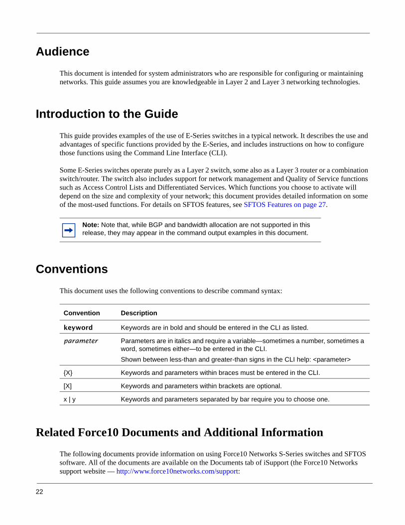
AudienceThis document is intended for system administrators who are responsible for configuring or maintaining networks. This guide assumes you are knowledgeable in Layer 2 and Layer 3 networking technologies.
Introduction to the GuideThis guide provides examples of the use of E-Series switches in a typical network. It describes the use and advantages of specific functions provided by the E-Series, and includes instructions on how to configure those functions using the Command Line Interface (CLI).
Some E-Series switches operate purely as a Layer 2 switch, some also as a Layer 3 router or a combination switch/router. The switch also includes support for network management and Quality of Service functions such as Access Control Lists and Differentiated Services. Which functions you choose to activate will depend on the size and complexity of your network; this document provides detailed information on some of the most-used functions. For details on SFTOS features, see SFTOS Features on page 27.
ConventionsThis document uses the following conventions to describe command syntax:
Related Force10 Documents and Additional Information
The following documents provide information on using Force10 Networks S-Series switches and SFTOS software. All of the documents are available on the Documents tab of iSupport (the Force10 Networks support website — http://www.force10networks.com/support:
Note: Note that, while BGP and bandwidth allocation are not supported in this release, they may appear in the command output examples in this document.
Convention Description
keyword Keywords are in bold and should be entered in the CLI as listed.
parameter Parameters are in italics and require a variable—sometimes a number, sometimes a word, sometimes either—to be entered in the CLI. Shown between less-than and greater-than signs in the CLI help: <parameter>
{X} Keywords and parameters within braces must be entered in the CLI.
[X] Keywords and parameters within brackets are optional.
x | y Keywords and parameters separated by bar require you to choose one.

SFTOS Configuration Guide, Version 2.5.3.0 23
• SFTOS Command Reference• SFTOS Configuration Guide• SFTOS and S-Series Release Notes• S50 Quick Reference (also included as a printed booklet with the system)• Hardware installation guides• MIBs files• S-Series Tech Tips and FAQ
Except for the Tech Tips and FAQ documents, all of the documents listed above are also on the S-Series CD-ROM. Training slides are also on the S-Series CD-ROM. Currently, access to user documentation on iSupport (see The iSupport Website on page 24) is available without a customer account. However, in the future, if you need to request an account for access, you can do so through that website.
Contact InformationFor technical support, see The iSupport Website on page 24. For other questions, contact Force10 using the following address:
Force10 Networks, Inc.350 Holger WaySan Jose, CA 95134USA
Documentation Feedback
If appropriate, please include the following information with your comments:
• Document name• Document part number• Page number• Software release version

24
Technical Support
The iSupport Website
Force10 iSupport provides a range of support programs to assist you with effectively using Force10 equipment and mitigating the impact of network outages. Through iSupport you can obtain technical information regarding Force10 products, access to software upgrades and patches, and open and manage your Technical Assistance Center (TAC) cases. Force10 iSupport provides integrated, secure access to these services.
Accessing iSupport Services
The URL for iSupport is www.force10networks.com/support/. To access iSupport services you must have a userid and password. If you do not have one, you can request one at the website:
1. On the Force10 Networks iSupport page, click the Account Request link.
2. Fill out the User Account Request form and click Send. You will receive your userid and password by email.
3. To access iSupport services, click the Log in link, and enter your userid and password.
Contacting the Technical Assistance Center
How to Contact Force10 TAC
Log in to iSupport at www.force10networks.com/support/, and select the Service Request tab.
Information to Submit When Opening a Support Case
• Your name, company name, phone number, and email address• Preferred method of contact• Model number• Software version number• Symptom description• Screen shots illustrating the symptom, including any error messages• Serial number, if requesting an RMA
Managing Your Case Log in to iSupport, and select the Service Request tab to view all open cases and RMAs.
Downloading Software Updates
Log in to iSupport, and select the Software Center tab.
Technical Documentation Log in to iSupport, and select the Documents tab. This page can be accessed without logging in via the Documentation link on the iSupport page.
Contact Information E-mail: [email protected]: www.force10networks.com/support/Telephone:US and Canada: 866.965.5800International: 408.965.5800

SFTOS Configuration Guide, Version 2.5.3.0 25
For more on using the iSupport website and accessing services, see the Force10 Service and Support Guide.

26

SFTOS Configuration Guide, Version 2.5.3.0 27
This chapter contains these major sections:
• Overview of SFTOS Features on page 27• Layer 2 Package Feature Details on page 28• Layer 3 Package Feature Details on page 30• Notable Differences between S-Series and E-Series on page 31• Port Naming Convention on page 33The SFTOS software is available in two packages—the “Layer 2 Package” (“Switching”) and the “Layer 3 Package” (“Routing”). The Layer 2 Package consists of the core software that comes installed on every S-Series switch (with the exception of the Stacking module, which is not included on the S2410), while the Layer 3 Package includes both the core software and software that supports Layer 3 of the OSI 7-Layer Model. The Layer 3 Package is only available for some S-Series models.
Overview of SFTOS FeaturesThe functions supported by SFTOS software include:
• Access control lists, used to control access to specified resources (see Using Differentiated Services (DiffServ) on page 185)
• Differentiated Services, which you can use to define traffic classes and how they will be treated, including traffic acceptance, transmission and bandwidth guarantees. See Using Differentiated Services (DiffServ) on page 185.
• Layer 2 Switching:• Bridging support (the default) for IEEE 802.1D — Spanning Tree plus IEEE 802.1w — Rapid
Reconfiguration and IEEE 802.1s — Multiple Spanning Tree (see Chapter 9, Spanning Tree)• Virtual LAN (VLAN) operation conforming to IEEE 802.1Q, including Generic Attribute
Registration Protocol (GARP), GARP Multicast Registration Protocol (GMRP) and GARP VLAN Registration Protocol (GVRP) (see VLANs on page 215)
• Support for extensions to the Ethernet protocol: — VLAN tagging, required for VLAN support (formerly IEEE 802.3ac, now included in
IEEE 802.3-2002)— Link Aggregation, which you may choose to implement to improve bandwidth and
reliability for critical connections (formerly IEEE 802.3ad) (see Chapter 10, Link Aggregation) (see also Chapter 16, Layer 3 Routing, for use of LAGs in Layer 3)
Chapter 1 SFTOS Features

28
— Flow Control at the MAC layer: you may configure the switch or a port to temporarily halt traffic when necessary to prevent overload (formerly IEEE 802.3x)
• Additional functions you can use to manage the network including IGMP Snooping (see Chapter 14, IGMP Snooping), Port Mirroring (see Chapter 15, Port Mirroring), and Broadcast Storm Recovery.
• Layer 3 Routing (see Chapter 16, Layer 3 Routing)• Base routing protocols, including support for the Address Resolution Protocol (ARP), IP
Mapping, the Internet Control Message Protocol (ICMP) and Classless Inter-Domain Routing (CIDR)
• Support for protocols used by routers to exchange network topology information:— Routing Information Protocol (RIP) versions 1 and 2, recommended for use in small
to medium sized networks— Open Shortest Path First (OSPF) version 2, used in larger, more complex networks
• Support for the Virtual Router Redundancy Protocol (VRRP) used to improve the reliability of network connections
• Support for the MD5 Message-Digest Algorithm defined in RFC 1321 used for digital signature applications
• Support for the use of Dynamic Host Configuration Protocol (DHCP) to assign IP addresses, including the Relay Agent Information option defined in RFC 3046
• VLAN Routing (see VLAN Routing on page 270): Allows traffic received on a VLAN port to be processed by the Layer 3 routing function.
Layer 2 Package Feature DetailsThe core Layer 2 Package software provides support for the following features:
Basic Routing and Switching Support• BootP (RFC 951, RFC 1542)• BootP/DHCP Relay and Server (RFC 2131)• Host Requirements (RFC 1122)• UDP (RFC 768)• IP (RFC 791)• ICMP (RFC 792)• TCP (RFC 793)• STP (Spanning Tree Protocol) (IEEE 802.1d)• Rapid Spanning Tree (IEEE 802.1w)• MSTP (IEEE 802.1s)• 10 GigE (IEEE 802.3ae)• 1000 Base-T (IEEE 802.3ab)• Flow Control (IEEE 802.3x)• IEEE 802.3ad

SFTOS Configuration Guide, Version 2.5.3.0 29
• 16k MAC Address Table• Jumbo Frame Support
QoS• 802.1p Priority Marking• ACL Entries (L2 + L3)• Bandwidth-based Rate Limiting• Priority Queues• Layer 2 Classification• Layer 3 DSCP• Wirespeed ACLs (L2/L3/L4)
VLAN• IEEE 802.1q Support• Frame Extensions (IEEE 802.3ac)• GVRP, GARP, GMRP• Port-based VLANs• Protocol-based VLANs• Supported Number of VLANs
Multicast Protocols• IGMP Snooping• Layer 2 Multicast Forwarding
Security and Packet Control Features• Access Profiles on Routing Protocols• DOS Protection• IEEE 802.1x• Ingress Rate Limiting• Login Access Control• MAC-based Port Security• Port Mirroring• RADIUS• SSH2 Server Support
Management• External Redundant Power System

30
• HTML-based Management• HTTPS/SSL• RMON Groups• SNMP v1/v2c• SNTP Support• SSHv2• Syslog• Telnet (RFC 854)• TFTP (RFC 783)
Stacking• Stacking Multiple Units• LAG across Units in a Stack• Hot Insertion and Removal of Units in a Stack• Auto Master Election• Auto Configuration
Layer 3 Package Feature DetailsThe “Layer 3 Package” (“Routing image”) version (optional for certain S-Series models) of SFTOS includes all of the features listed above, along with the following features.
Extended Routing and Switching Support• 4k IPv4 Routing Table Entry• ARP (RFC 826)• CIDR (RFC 1519)• IPv4 (RFC 1812)• IPv4 Router Discovery (RFC 1256)• Proxy ARP (RFC 1027)• VRRP (RFC 2338)
Routing Protocol Support• RIPv1/v2• OSPF (RFC 2328, 1587, 1765, 2370)• Static Routes

SFTOS Configuration Guide, Version 2.5.3.0 31
Multicast Protocols• IGMP v1/v2 (RFC 1112, 2236)• PIM-SM-edge• DVMRP• PIM-DM
Management• ECMP
Notable Differences between S-Series and E-SeriesThis section describes the major differences in how command usage on the S-Series differs from the E-Series. Users familiar with the E-Series CLI will notice enough similarities in the CLI environment on the S-Series that they can quickly learn the variations in syntax and usage.
The primary goal of SFTOS Release 2.3 (and associated dot releases) was to make SFTOS more like FTOS. Of course, there are still differences because FTOS requires more commands, usually with more detailed options than in SFTOS, to support the more complex E-Series switches.
• The aaa authentication command: This FTOS command is available in SFTOS as authentication.• CLI command modes: SFTOS Release 2.3 modifies the command mode tree of SFTOS to be more
like FTOS, so that their modes are basically equivalent at the base, differing toward the leaves. • Creating a static route: The SFTOS command ip route supports only IP addresses for setting the
next-hop router, while ip route in the FTOS also supports physical interfaces. In other words:— In SFTOS Layer 3, you can only put an IP address as the source and destination:
ip route source-ip-address mask destination-ip-address — In FTOS, you can have a physical interface as a destination as well as an IP address:
ip route source-ip-address mask {destination interface | ip address}
• Displaying the MAC address table: Both FTOS and SFTOS have the show mac-address-table
command, but the SFTOS command provided different results than the FTOS command before SFTOS Release 2.3. The SFTOS syntax still contains the unit/slot/port form cited above, for example, show mac-addr-table interface 1/0/4.
• Displaying port information: FTOS and SFTOS have different sets of the show interface and show
interfaces commands. SFTOS also has a similar show port command for displaying whether a port is up or not, as shown in Figure 1:
Note: As you can see in some command descriptions, below, the major difference between SFTOS and FTOS is that in commands that contain a port reference, FTOS expresses the location as slot/port, while SFTOS uses unit/slot/port. For physical identifiers, unit is the stack member number in an S50 stack. For details, see Port Naming Convention on page 33.

32
Figure 1 Using the show port Command
• Displaying system information: The FTOS command show linecard is similar to show version in SFTOS, which shows basic information, including the running software version and up time. Other similar commands in SFTOS are show hardware and show sysinfo, and show tech-support provides the results of a group of those similar commands.
• The terminal length command: This FTOS command (often shortened to “term len”) was not available in SFTOS before SFTOS Release 2.3.
• The service timestamps command: This FTOS command is not available in SFTOS. SFTOS sets timestamps automatically.
• OSPF area ID: In SFTOS, OSPF only accepts the IP address format for the area ID, not the number within a range.
• File management:
• Management address: SFTOS Release 2.3 modifies the creation of a management address to be more like FTOS, but there are still some differences.
• Setting the size of the logging buffer: The FTOS command logging buffered has a parameter that enables you to set the size of the buffer, while SFTOS does not. Both FTOS and SFTOS invoke debug logging with the number 7 as the severity level parameter. For example, the SFTOS command is logging buffered 7.
• Software naming convention: E-Series software uses this naming convention: FTOS-EF-x.x.x.x Through version 2.3.1.5, the S-Series used a different format that ends with an “.opr” extension.
Table 1 Switch File Management
FTOS references system file locations as: SFTOS references system file locations as:
flash:// nvram:
slot0:// system:
(Force10 S50) #show port 1/0/2
Admin Physical Physical Link Link LACP
Intf Type Mode Mode Status Status Trap Mode
------ ------ ------- ---------- ---------- ------ ------- -------1/0/2 Enable Auto Down Enable Enable
(Force10 S50) #
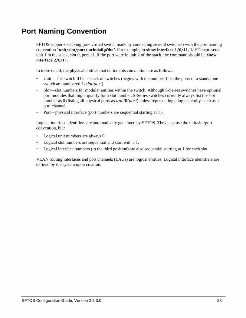
SFTOS Configuration Guide, Version 2.5.3.0 33
Port Naming ConventionSFTOS supports stacking (one virtual switch made by connecting several switches) with the port naming convention “unit/slot/port<lucindaRgOb>”. For example, in show interface 1/0/11, 1/0/11 represents unit 1 in the stack, slot 0, port 11. If the port were in unit 2 of the stack, the command should be show
interface 2/0/11.
In more detail, the physical entities that define this convention are as follows:
• Unit—The switch ID in a stack of switches (begins with the number 1, so the ports of a standalone switch are numbered 1/slot/port).
• Slot—slot numbers for modular entities within the switch. Although S-Series switches have optional port modules that might qualify for a slot number, S-Series switches currently always list the slot number as 0 (listing all physical ports as unit/0/port) unless representing a logical entity, such as a port channel.
• Port—physical interface (port numbers are sequential starting at 1).
Logical interface identifiers are automatically generated by SFTOS. They also use the unit/slot/port convention, but:
• Logical unit numbers are always 0.• Logical slot numbers are sequential and start with a 1.• Logical interface numbers (in the third position) are also sequential starting at 1 for each slot.
VLAN routing interfaces and port channels (LAGs) are logical entities. Logical interface identifiers are defined by the system upon creation.

34

SFTOS Configuration Guide, Version 2.5.3.0 35
This chapter summarizes the following basic tasks:• Connecting to the Console Port on page 37• Command Line Interface (CLI) Overview on page 39• Checking Status on page 40
— Displaying Statistics on page 44— Viewing the Software Version and Switch Numbers on page 40— Showing Network Settings on page 42— Displaying Supported Features and System Up-time on page 43— Verifying Details about the Switch on page 41
• User Management on page 44— Creating a User and Password on page 45— Showing and Removing Created Users on page 45— Setting SNMP Read/Write Access on page 45— Setting the Enable Password on page 46
• Enabling Interfaces on page 46— Enabling Ports on page 46— Setting the Management IP Address on page 47— Enabling Telnet to the Switch on page 48— Configuring an Interface with an IP Address on page 48— Setting up SNMP Management on page 49
• Creating VLANS on page 49• Managing Configuration and Software Files on page 51
— Downloading and Uploading Files on page 52— Downloading a Software Image on page 54— Installing System Software on page 58— Managing the Configuration on page 64— Saving the Startup Configuration to the Network on page 66— Clearing the Running Configuration on page 65— Configuring from the Network on page 66— Restoring the System to the Factory Default Configuration on page 67— Resetting the Pre-configured System on page 67— Using Configuration Scripts on page 68— Creating a Configuration Script on page 68
Chapter 2 Getting Started

36
Setting up a Management Connection to the SwitchYou have a choice of methods to manage the switch. You can access the SFTOS command line interface (CLI) through either the console port on the switch or through an out-of-band method such as Telnet or SSH. To use any method other than the console port (VT100 emulation), you must first configure a management IP address on the switch. This chapter includes the procedures that connect you to the console and to set up a management IP address:
• Console connection (VT100 interface): See Connecting to the Console Port on page 37.• Management IP address: See Setting the Management IP Address on page 47. See also Showing
Network Settings on page 42.
After setting up the management IP address, you can use one of the following connection methods:
• Simple Network Management Protocol (SNMP): For details on setting up SNMP, see Setting SNMP Read/Write Access on page 45 and Setting up SNMP Management on page 80.
• Telnet: See Enabling Telnet to the Switch on page 48. To use SSH to enable secure access over Telnet, see Enabling SSH on page 150.
Note: The Force10 Management System (FTMS) is a graphical network management software product that provides a global view of your complete Force10 network. FTMS includes Node Manager, which not only provides GUI-based device management, it also includes the ability to execute CLI commands, either individually from Node Manager or by having Node Manager open a Telnet window to the device.
Note: You can also use a configuration script to set up the switch. The maximum number of configuration file command lines is 2000. See Using Configuration Scripts on page 68.

SFTOS Configuration Guide, Version 2.5.3.0 37
Connecting to the Console PortTo access the console port, follow the procedure below:
Step Task
1 Caution: Install a straight-through RJ-45 copper cable (for example, an Ethernet cable) into the console port. This is different from many other implementations that require a crossover (rollover) cable. If connecting to a terminal server and using an Ethernet crossover cable, daisychain another crossover cable to effectively get a straight-through cable connection. Many console terminal servers use octopus cables that are crossover cables. As above, connect an additional crossover cable.
2 Connect the RJ-45/DB-9 adapter that is shipped with the switch to the RJ-45 cable. Note: The console port pinout:
Pin 1 = NCPin 2 = NCPin 3 = RXDPin 4 = GNDPin 5 = GNDPin 6 = TXDPin 7 = NCPin 8 = NC
3 Connect the adapter to a laptop.
4 Once a connection is established, ensure the following terminal settings (default settings) at both ends: 9600 baud rate, no parity, 8 data bits, 1 stop bit, no flow control (console port only). If you want to change the settings (such as if you want to download software at a higher speed), you must change the serial configuration on both the switch and computer. See the command options in the following step. For more on changing settings, see the hardware guide or the Quick Reference.
fn00162s50

38
For more on setting serial settings, see the hardware guide for your system or the System Management Commands chapter in the SFTOS Command Reference.
The default CLI user, admin, has read/write access, with no password until you create one. For details, see Creating a User and Password on page 45. There is also one mode-level password. See Setting the Enable Password on page 46.
5 Enter Line Config mode by logging in, entering Privileged Exec mode (enable command), Global Config mode (config command), then lineconfig. In Line Config mode, use the serial timeout command to set the console inactivity timeout (0 for no timeout; up to 160 minutes):
Figure 2 Using the Line Config Mode and the serial timeout Command
6 To display serial (console) port configuration, enter the command show serial:
Figure 3 Using the show serial Command
Step Task (continued)
User:adminPassword:Force10 >enablePassword:
Force10 #configureForce10 (Config)#lineconfigForce10 (Line)#? exit To exit from the mode.serial Configure EIA-232 parameters and inactivity timeout.session-limit Configure the maximum number of outbound telnet sessions allowed.session-timeout Configure the outbound telnet login inactivity timeout.transport Displays the protocol list to use for outgoing connections.Force10 (Line)#serial ?baudrate Set the serial baudrate.timeout Configure the serial port login inactivity timeout.
Force10 (Line)#serial timeout ?<0-160> Enter time in minutes.
Force10 (Line)#serial timeout 0Force10 (Line)#exitForce10 (Config)#
Force10 #show serial
Serial Port Login Timeout (minutes)............ 30Baud Rate (bps)................................ 9600Character Size (bits).......................... 8Flow Control................................... DisableStop Bits...................................... 1Parity......................................... none

SFTOS Configuration Guide, Version 2.5.3.0 39
Command Line Interface (CLI) OverviewThe SFTOS Command Line Interface (CLI) is the main way to manage S-Series switches. You can use the CLI through:
• Console port: As described above (Connecting to the Console Port on page 37), the port is the one located at bottom right of the front panel (Use only the console port of the management unit in an S50 stack. The management unit is indicated by the lit LED labeled “PRI” on the top left of the S50 front panel.)
• Telnet (including SSH): You can use any connected and enabled port in the management VLAN (configured with a Management IP address). See Setting the Management IP Address on page 47.
CLI Command Modes
The CLI of SFTOS follows the industry convention of mode-based access to functionality. In other words, you specify through CLI commands which mode you want to access, and then, in that mode, you enter commands that are specific to that mode. For example, if you want to configure a VLAN, you would first enter VLAN mode. For details on using the modes, see Chapter 4, Using the Command Line Interface, in the SFTOS Command Reference.
The main CLI command modes and the default prompts are as follows:
• User Exec: hostname >
• Privileged Exec (also called “enable mode”): hostname #• Global Config (also called “config mode”): hostname (Config)#• Interface Config: hostname (Interface ifnumber)#• Interface VLAN Config (often shortened to “VLAN mode”): hostname (conf-if-vl-vlan-id)
Here is an example of navigating to these modes:
Figure 4 Example of Navigating to CLI Modes
Note: The default text for the hostname part of the prompt is “Force10 S50”. You can modify that part of the prompt by using the hostname command. See Setting the Host Name Prompt on page 78.
Force10 >enablePassword:Force10 #configureForce10 (Config)#interface 1/0/5Force10 (Interface 1/0/5)#exitForce10 (Config)#interface vlan 20Force10 (conf-if-vl-20)#exitForce10 (Config)#exitForce10 #lineconfigForce10 (Line)#
Note: Note the use of “1/0/5”. For more on the port naming convention, see Port Naming Convention on page 33.

40
Getting Help From the CLI
The following help commands are the same as those found in the E-Series:
• Use “?” at the prompt to get a list of commands in that mode: “Force10# ?”• Use “?” with a partial command to see what initial command words in that mode begin with that string:
“Force10# i?”• Use “?” after a command or partial command to get a list of commands that start with that word:
“Force10# ip ?”
Controlling Pagination
Starting in SFTOS Release 2.3, you can use the terminal length command to set how much of the output of a CLI “show” command to display. Use the show terminal command to display the current setting of the terminal length command. For details, see the System Configuration Commands chapter in the SFTOS Command Line Reference.
Checking StatusSFTOS follows the industry convention of using “show” commands to generate status reports through the command interface.
Viewing the Software Version and Switch Numbers
If you are concerned that you might not have the correct software version, you can select from several commands to see the installed code version. The following is an example of using show switch , which you can execute in either User Exec or Privileged Exec modes:
Figure 5 Using the show switch Command
The Switch column shows the switch ID, which is useful if the switch is in a stack. For example, if the switch ID were 2, the switch’s physical interfaces would be identified as 2/0/port-number.
Force10 #show switch
Management Preconfig Plugged-in Switch CodeSwitch Status Model ID Model ID Status Version------ ------------ ------------- ------------- --------------------- --------1 Mgmt Switch SA-01-GE-48T SA-01-GE-48T OK 2.3.1
Force10 #

SFTOS Configuration Guide, Version 2.5.3.0 41
Verifying Details about the Switch
The following example is of the show switch unit command for getting more details about the switch:
Figure 6 Verifying Details about the Switch
You can also use the show hardware command to display the running code version. See the sample output in the section Downloading a Software Image on page 54.
The show version command displays more details about the software packages installed, and also the hardware present on the system. This command provides the details shown by the show hardware and show sysinfo commands, along with interface information, the u-boot version number, and the system image file version. The show tech-support command is the most lengthy, because it includes the output from each of these other commands:
• show version• show logging
• show eventlog • show port all• show memory
• show process cpu • show running-config
Because output from the show tech-support command is so lengthy, Force10 recommends that you set the storage buffer high on your terminal access program, then use the non-paged option — show tech-support non-paged — to collect the full report for off-line analysis.
Force10 #show switch
Management Preconfig Plugged-in Switch CodeSwitch Status Model ID Model ID Status Version------ ------------ ------------- ------------- --------------------- --------1 Mgmt Switch SA-01-GE-48T SA-01-GE-48T OK 2.3.1
Force10 #show switch 1Switch............................ 1Management Status................. Management SwitchHardware Management Preference.... UnassignedAdmin Management Preference....... 1Switch Type....................... 0x56950202Preconfigured Model Identifier.... SA-01-GE-48TPlugged-in Model Identifier....... SA-01-GE-48TSwitch Status..................... OKSwitch Description................ Expected Code Type................ 0x100b000Detected Code Version............. 2.3.1Detected Code in Flash............ 2.3.1Serial Number..................... DE4000106Up Time........................... 0 days 10 hrs 11 mins 52 secs

42
Showing Network SettingsExecute the show interface managementethernet command from either the User Exec or Privileged Exec modes. The resulting display, as shown in the example below, displays all the settings relating to IP-based management connections to the switch. The data includes the management IP address, subnet mask, default gateway, MAC information, etc., as shown below:
Figure 7 Using the show network Command to Display Network Settings
For details on setting up the management address, see Setting the Management IP Address on page 47. See also Setting up a Management Connection to the Switch on page 36.
.
Note: SFTOS v. 2.3 replaced the show network command with show interface managementethernet.
Force10 #show interface managementethernetIP Address..................................... 10.10.1.151Subnet Mask.................................... 255.255.255.0Default Gateway................................ 10.10.1.254Burned In MAC Address.......................... 00:01:E8:D5:A0:39Locally Administered MAC Address............... 00:00:00:00:00:00MAC Address Type............................... Burned InNetwork Configuration Protocol Current......... NoneManagement VLAN ID............................. 1Web Mode....................................... EnableJava Mode...................................... Disable
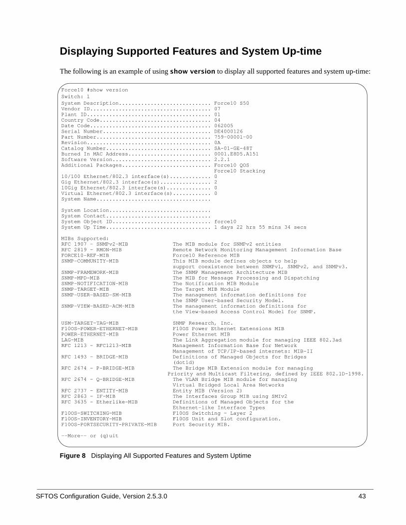
SFTOS Configuration Guide, Version 2.5.3.0 43
Displaying Supported Features and System Up-time
The following is an example of using show version to display all supported features and system up-time:
Figure 8 Displaying All Supported Features and System Uptime
Force10 #show version Switch: 1System Description............................. Force10 S50Vendor ID...................................... 07Plant ID....................................... 01Country Code................................... 04Date Code...................................... 062005Serial Number.................................. DE4000126Part Number.................................... 759-00001-00Revision....................................... 0ACatalog Number................................. SA-01-GE-48TBurned In MAC Address.......................... 0001.E8D5.A151Software Version............................... 2.2.1Additional Packages............................ Force10 QOS Force10 Stacking10/100 Ethernet/802.3 interface(s)............. 0Gig Ethernet/802.3 interface(s)................ 210Gig Ethernet/802.3 interface(s).............. 0Virtual Ethernet/802.3 interface(s)............ 0System Name....................................
System Location................................ System Contact................................. System Object ID............................... force10System Up Time................................. 1 days 22 hrs 55 mins 34 secs
MIBs Supported:RFC 1907 - SNMPv2-MIB The MIB module for SNMPv2 entitiesRFC 2819 - RMON-MIB Remote Network Monitoring Management Information BaseFORCE10-REF-MIB Force10 Reference MIBSNMP-COMMUNITY-MIB This MIB module defines objects to help support coexistence between SNMPv1, SNMPv2, and SNMPv3.SNMP-FRAMEWORK-MIB The SNMP Management Architecture MIBSNMP-MPD-MIB The MIB for Message Processing and DispatchingSNMP-NOTIFICATION-MIB The Notification MIB ModuleSNMP-TARGET-MIB The Target MIB ModuleSNMP-USER-BASED-SM-MIB The management information definitions for the SNMP User-based Security Model.SNMP-VIEW-BASED-ACM-MIB The management information definitions for the View-based Access Control Model for SNMP.
USM-TARGET-TAG-MIB SNMP Research, Inc.F10OS-POWER-ETHERNET-MIB F10OS Power Ethernet Extensions MIBPOWER-ETHERNET-MIB Power Ethernet MIBLAG-MIB The Link Aggregation module for managing IEEE 802.3adRFC 1213 - RFC1213-MIB Management Information Base for Network Management of TCP/IP-based internets: MIB-IIRFC 1493 - BRIDGE-MIB Definitions of Managed Objects for Bridges (dot1d)RFC 2674 - P-BRIDGE-MIB The Bridge MIB Extension module for managing Priority and Multicast Filtering, defined by IEEE 802.1D-1998.RFC 2674 - Q-BRIDGE-MIB The VLAN Bridge MIB module for managing Virtual Bridged Local Area NetworksRFC 2737 - ENTITY-MIB Entity MIB (Version 2)RFC 2863 - IF-MIB The Interfaces Group MIB using SMIv2RFC 3635 - Etherlike-MIB Definitions of Managed Objects for the Ethernet-like Interface TypesF10OS-SWITCHING-MIB F10OS Switching - Layer 2F10OS-INVENTORY-MIB F10OS Unit and Slot configuration.F10OS-PORTSECURITY-PRIVATE-MIB Port Security MIB.
--More-- or (q)uit

44
Displaying Statistics
Privileged Exec mode commands to display statistics include:• Switch summary statistics:
— show interface switchport
• Interface summary statistics:— show interface unit/slot/port
• Switch detailed statistics:— show interface ethernet switchport
• Interface detailed statistics:— show interface ethernet unit/slot/port
User ManagementThis section contains the following subsections:
• Creating a User and Password on page 45• Showing and Removing Created Users on page 45• Setting the Enable Password on page 46• Enabling Ports on page 46• Setting the Management IP Address on page 47
The default CLI user, admin, has read/write access, with no password until you create one (see Creating a User and Password on page 45). The only way to recover from a lost admin password is to reload the switch using facory defaults. See Restoring the System to the Factory Default Configuration on page 67.
You can also control user access through access control servers, such as TACACS+ and RADIUS and with SSH. See Chapter 8, Providing User Access Security on page 143 for details. The local users you create (up to six, including admin) all have read/write access.
There is one mode-level password — commonly called the “enable” password — that you can configure to allow the user to move from User Exec mode to Privileged Exec mode in the CLI. See Setting the Enable Password on page 46.

SFTOS Configuration Guide, Version 2.5.3.0 45
Creating a User and Password
The username passwd command creates the username and password in one statement. You can change a password either by reentering the command with the new password or by removing the user with the no username command and reentering the user with a new password.
Figure 9 Creating a User and a Password
Showing and Removing Created UsersAn alternative to the no username command shown above is to use the clear pass command to delete all created users. The following example shows the show users command and the clear pass command:
Figure 10 Showing Created Users
Setting SNMP Read/Write Access
The command users snmpv3 accessmode username {readonly | readwrite} enables you to set SNMP privileges for specific users. As used above (Showing and Removing Created Users on page 45), the show users command displays the read and write privileges for each defined user:
Note: SFTOS 2.5.1.3 adds support for the following special characters: , . { } | , in other words, period, comma, open bracket, close bracket, and bar.
Force10 (Config)#username w_turner passwd willspwdUser login name and password are set.
Force10 (Config)#no username w_turner
Force10 (Config)#username w_turner passwd newpwdUser login name and password are set.Password Changed!
Force10 #show usersSNMPv3 SNMPv3 SNMPv3
User Name User Access Mode Access Mode Authentication Encryption---------- ---------------- ----------- -------------- ----------admin Read/Write Read/Write None Nonew_turner Read/Write Read Only None None
Force10 #clear passAre you sure you want to reset all passwords? (y/n)yPasswords Reset!

46
Figure 11 Creating and Displaying SNMP Access Levels
For details on SNMP, see Setting up SNMP Management on page 80.
Setting the Enable Password
To change the Privileged Exec password (also called the “Enable” password) in SFTOS Version 2.3.1 and above, you do so in Global Config mode. Enter enable passwd, press Enter, and enter a new password:
Figure 12 Setting the Enable Password
Enabling InterfacesThis section covers the enabling of ports, VLANs, and management interfaces (Telnet, SNMP):
• Enabling Ports on page 46• Setting the Management IP Address on page 47• Enabling Telnet to the Switch on page 48• Configuring an Interface with an IP Address on page 48• Using the Show IP Interface Command on page 49• Setting up SNMP Management on page 49
Enabling Ports
When the switch is first installed, all ports are disabled. To enable all ports in Layer 2, enter no shutdown all in Global Config mode (see Figure 13). Alternatively, you can use the no shutdown command in Interface Config mode (for the selected interface — see Figure 14).
Force10 (Config)#users snmpv3 accessmode student2 readwriteForce10 #show users
SNMPv3 SNMPv3 SNMPv3User Name User Access Mode Access Mode Authentication Encryption---------- ---------------- ----------- -------------- ----------admin Read/Write Read/Write None Nonestudent1 Read Only Read Only None Nonestudent2 Read Only Read/Write None None
Force10 #enable passwdEnter new password:*******Confirm new password:*******Password Changed!

SFTOS Configuration Guide, Version 2.5.3.0 47
Figure 13 Enabling Ports Globally
Figure 14 Enabling an Individual Port
For more on setting up ports, see Configuring Interfaces on page 119.
Setting the Management IP Address
On first startup, you have management access only through the console port. If you want to manage the switch through an IP-based access method (Telnet, SSH, SNMP, TFTP, etc.), you must configure a management IP interface, using the following the procedure.
By default, the management address is reachable from all ports on the default VLAN, VLAN 1. One or more ports in that VLAN must be enabled, as described in Enabling Ports, above. To change to another VLAN, see Setting Up the Management VLAN on page 50.
After you enable and connect ports in the management VLAN and configure the management IP address, as described above, you can manage the switch through a variety of means. The following procedures describe enabling Telnet and SNMP, respectively.
Step Command Syntax Command Mode Purpose
1 show interface managementethernet
User Exec or Privileged Exec
Display current management IP configuration.
2 management route default gateway
Global Config Set the IP gateway of the management interface.
3 interface managementethernet Global Config Invoke the (Config-if-ma)# prompt.
4 ip address ipaddr subnetmask (Config-if-ma)# prompt within the Global Config mode
Set the IP address and subnet mask of the management interface.
Note: Creating a management IP address is supported by both the Layer 2 (Switching) and Layer 3 (Routing) licenses of SFTOS.
Force10 >enableForce10 #configForce10 (Config)#no shutdown allForce10 (Config)#
Force10 >enableForce10 #configForce10 (Config)#interface 1/0/22Force10 (Interface 1/0/22)#no shutdown

48
Enabling Telnet to the Switch
Access to the switch through Telnet is disabled by default. If you want to access the switch through an SSH client, you would leave Telnet disabled and set up the SSH connection, as described in Enabling Secure Management with SSH on page 149.
To enable Telnet access, execute the ip telnet server enable command.
Configuring an Interface with an IP Address
To assign an IP address to an interface, use the following commands:
IP configuration takes precedence over VLAN configuration on a port. Therefore, configuring an IP Address and ‘routing’ on an interface disables participation in VLANs on that interface.
Note: You must have the optional SFTOS Layer 3 Package installed to configure routing commands and to set IP addressing an interface. Use the show version command (see Figure 8 on page 43) to determine what software is installed.
Command Syntax Command Mode Purpose
ip routing Global Config Enables routing for the switch.
ip address Interface Config Configures an IP address on an interface. The IP address may be a secondary IP address.
Note: You must configure ip routing at a global level, AND ‘routing’ at an interface level for you to be able to ping from, and to, the address.Note: To configure the management interface with an IP address, see Setting the Management IP Address on page 47.
Force10 #configureForce10 (Config)#ip routingForce10 (Config)#interface 1/0/3Force10 (Interface 1/0/3)#ip address 50.0.0.2 255.255.255.0Force10 (Interface 1/0/3)#routing

SFTOS Configuration Guide, Version 2.5.3.0 49
Using the Show IP Interface Command
Use the show ip interface command to display information about a particular IP interface:
Figure 15 Using the show ip interface Command
Use the show ip interface brief command to display a smaller set of information about all IP interfaces.
Figure 16 Using the show ip interface brief Command
Setting up SNMP Management
To use an SNMP-based network management tool, you must enable a management IP address for the switch, as described above (see Setting the Management IP Address on page 47) and have the switch join an SNMP community (see Setting up SNMP Management on page 80 in the Management chapter). Most SNMP traps are enabled by default. For details, see Managing SNMP Traps on page 81 in the Management chapter.
Creating VLANSThis section contains these subsections:
• Important Points to Remember — VLANs• Setting Up the Management VLAN• Creating a VLAN on page 50
Force10 #show ip interface 1/0/3
IP Address..................................... 50.0.0.2Subnet Mask.................................... 255.255.255.0Routing Mode................................... EnableAdministrative Mode............................ EnableForward Net Directed Broadcasts................ DisableActive State................................... ActiveLink Speed Data Rate........................... 1000 FullMAC Address.................................... 00:03:E8:0D:20:01Encapsulation Type............................. EthernetIP Mtu......................................... 1500
Force10 #
Force10 #show ip interface brief
Netdir MultiInterface IP Address IP Mask Bcast CastFwd--------- --------------- --------------- -------- --------1/0/3 50.0.0.2 255.255.255.0 Disable Disable1/0/4 66.1.1.1 255.255.255.0 Disable Disable
Force10 #
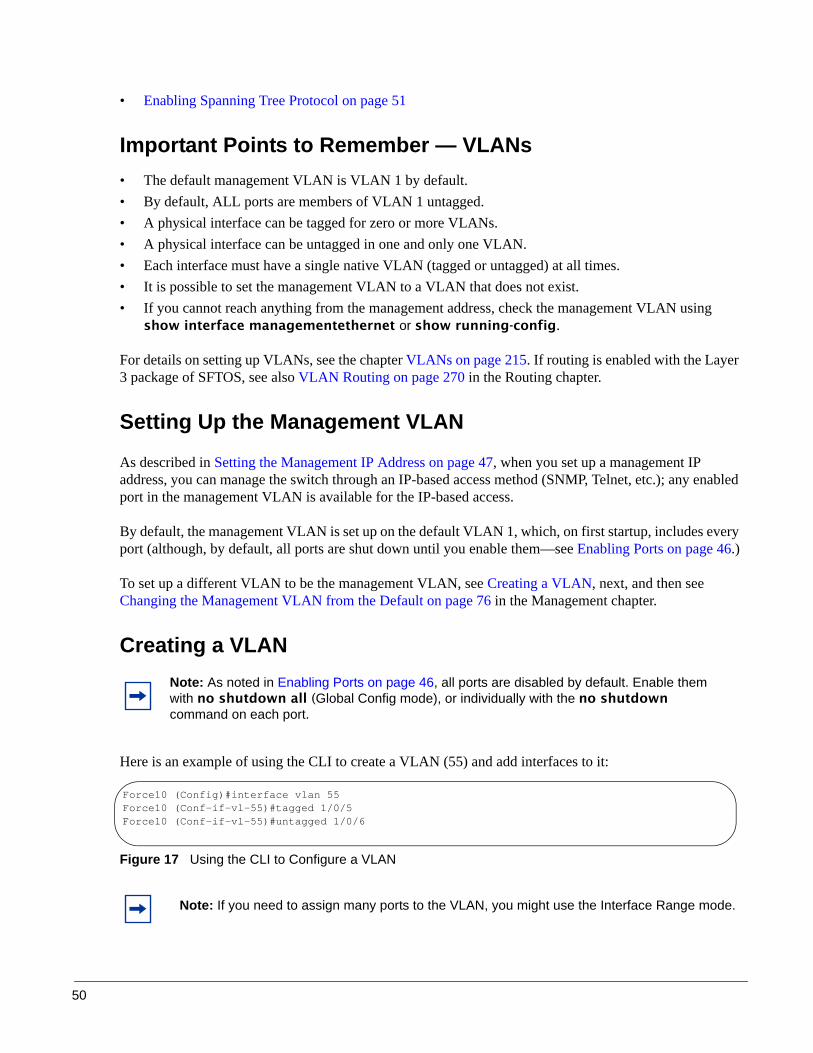
50
• Enabling Spanning Tree Protocol on page 51
Important Points to Remember — VLANs• The default management VLAN is VLAN 1 by default.• By default, ALL ports are members of VLAN 1 untagged.• A physical interface can be tagged for zero or more VLANs.• A physical interface can be untagged in one and only one VLAN.• Each interface must have a single native VLAN (tagged or untagged) at all times.• It is possible to set the management VLAN to a VLAN that does not exist.• If you cannot reach anything from the management address, check the management VLAN using
show interface managementethernet or show running-config.
For details on setting up VLANs, see the chapter VLANs on page 215. If routing is enabled with the Layer 3 package of SFTOS, see also VLAN Routing on page 270 in the Routing chapter.
Setting Up the Management VLAN
As described in Setting the Management IP Address on page 47, when you set up a management IP address, you can manage the switch through an IP-based access method (SNMP, Telnet, etc.); any enabled port in the management VLAN is available for the IP-based access.
By default, the management VLAN is set up on the default VLAN 1, which, on first startup, includes every port (although, by default, all ports are shut down until you enable them—see Enabling Ports on page 46.)
To set up a different VLAN to be the management VLAN, see Creating a VLAN, next, and then see Changing the Management VLAN from the Default on page 76 in the Management chapter.
Creating a VLAN
Here is an example of using the CLI to create a VLAN (55) and add interfaces to it:
Figure 17 Using the CLI to Configure a VLAN
Note: As noted in Enabling Ports on page 46, all ports are disabled by default. Enable them with no shutdown all (Global Config mode), or individually with the no shutdown command on each port.
Note: If you need to assign many ports to the VLAN, you might use the Interface Range mode.
Force10 (Config)#interface vlan 55Force10 (Conf-if-vl-55)#tagged 1/0/5Force10 (Conf-if-vl-55)#untagged 1/0/6

SFTOS Configuration Guide, Version 2.5.3.0 51
The tagged 1/0/5 command in Figure 17 not only assigns the port to VLAN 55, it also sets the Port VLAN ID (PVID) to 55, causing untagged frames transmitted by this port to be tagged as part of traffic for VLAN 55.
Enabling Spanning Tree Protocol
Spanning Tree Protocol (STP) is off by default. Enable STP globally, and then enable STP on the desired ports. Using the CLI, you can enable spanning tree globally, and on all the ports with just two commands — spanning-tree and spanning-tree port mode enable all:
Figure 18 Example of Entering STP Commands in CLI
For more on Spanning Tree Protocol, see the chapter Spanning Tree on page 153 and the Spanning Tree (STP) Commands chapter in the SFTOS Command Reference.
Managing Configuration and Software FilesThis section contains the following major subsections, in this order:
• Important Points to Remember — Files on page 52• Downloading and Uploading Files on page 52• Downloading a Software Image on page 54• Installing System Software on page 58• Managing the Configuration on page 64• Using Configuration Scripts on page 68
Force10 #configureForce10 (Config)#spanning-treeForce10 (Config)#spanning-tree port mode enable allForce10 (Config)#exitForce10 #show spanning-tree summary
Spanning Tree Adminmode........... EnabledSpanning Tree Version............. IEEE 802.1sConfiguration Name................ 00-01-E8-D5-A0-F7Configuration Revision Level...... 0Configuration Digest Key..........0xac36177f50283cd4b83821d8ab26de62Configuration Format Selector..... 0No MST instances to display.
Force10 #show spanning-tree interface 1/0/1Hello Time..................................... 0Port Mode...................................... EnabledPort Up Time Since Counters Last Cleared....... 0 day 0 hr 19 min 38 secSTP BPDUs Transmitted.......................... 2STP BPDUs Received............................. 593RSTP BPDUs Transmitted......................... 0RSTP BPDUs Received............................ 0

52
The S-Series switch contains several discrete system management files, including a startup configuration file (“startup-config”), a running-config file, SFTOS, and a system software file (“boot code”). There are various reasons why you might want to replace one or the other. For example, for the configuration file, if you lose your password, you will need to replace the running configuration with the factory default. If you back up the startup-config file, you can copy that file to the rebooted switch to be used as the configuration on the next reload.
Regarding the SFTOS software (“software image”), if you move an S50 into a stack, that S50 must run the same software version as the other members of the stack. This section details procedures that pertain to those file management activities.
Important Points to Remember — Files• Beginning with SFTOS Version 2.3, when you save the running-config to the startup-config file, the
startup-config is converted to text, if it is not already. Upgrading the software to Version 2.3 or above automatically invokes a conversion of the binary configuration file to text. The conversion also includes updating configuration statements to statements that conform to the current version.
• While you cannot cut and paste the configuration file, you can cut and paste output from the show running-config (show run) command into a text file, and paste it in through Telnet or console. For a sample of the output, see the show running-config command in the SFTOS Command Reference Guide, or see Displaying VLAN Information on page 242 in this guide.
Downloading and Uploading Files
Use the copy command (in Privileged Exec mode) to download or upload various files using TFTP or Xmodem. The following files can be uploaded from the switch: • CLI banner (copy nvram:clibanner)• Event log (nvram:errorlog): This log is also called the persistent log. For details on the log, see
Using the Persistent Event Log on page 95.• System log (nvram:log): This log is also called the buffered log or message log. For details on the
log, see Displaying the System Log on page 93.• configuration script (nvram:script scriptname)
• startup configuration file (nvram:startup-config)• trap log (nvram:traplog): For details on the log, see Displaying the SNMP Trap Log on page 96.
When using TFTP, the following example command shows the format for uploading from the switch. Enter: copy nvram:startup-config tftp://tftp_server_ip_address/path/filenameIn place of tftp_server_ip_address, specify a URL for the TFTP destination. An example of path/filename is s50/clibanner.txt. See also Managing the Configuration on page 64.
If you use Xmodem instead, the syntax is xmodem:path/filename .
Using TFTP, the following commands download files to the switch:
copy tftp://tftp_server_ip_address/path/filename nvram:startup-configcopy tftp://tftp_server_ip_address/path/filename system:image (previous to SFTOS 2.5.1)

SFTOS Configuration Guide, Version 2.5.3.0 53
copy tftp://tftp_server_ip_address/path/filename {image1 | image2} (starting with SFTOS 2.5.1)(For details on downloading SFTOS, see Installing System Software on page 58.)copy tftp://tftp_server_ip_address/path/filename nvram:scriptcopy tftp://tftp_server_ip_address/path/filename nvram:sslpem-rootcopy tftp://tftp_server_ip_address/path/filename nvram:sslpem-servercopy tftp://tftp_server_ip_address/path/filename nvram:sslpem-dhweakcopy tftp://tftp_server_ip_address/path/filename nvram:sslpem-dhstrongcopy tftp://tftp_server_ip_address/path/filename nvram:sshkey-rsa1copy tftp://tftp_server_ip_address/path/filename nvram:sshkey-rsa2copy tftp://tftp_server_ip_address/path/filename nvram:sshkey-dsacopy tftp://tftp_server_ip_address/path/filename nvram:clibanner
For example: #copy tftp://192.168.0.10/dsa.key nvram:sshkey-dsa
For information on the SSL and SSH files listed above, see the Secure Communications folder on the S-Series Documentation and Software CD-ROM.
Points to Remember when Transferring FilesPoints to remember when downloading software code or configuration files include:
• Code:— In SFTOS 2.5.1.x , a download of SFTOS overwrites SFTOS code in the designated section of
flash memory, denoted by the copy command with the location names image1 and image2. • Configuration:
— Configuration is stored in NVRAM.— Active configuration is distinct from the stored configuration.— Changes to active configuration are not retained across resets unless explicitly saved.— A download replaces the stored configuration.— A download is stopped if a configuration error is found.
• Upload code, configuration, or logs.• File transfer uses Xmodem or TFTP depending on platform.• Specify the following TFTP server information.
— IP address— File path (up to 31 characters)— File name (up to 31 characters)
• Progress of the TFTP transfer is displayed.• Use dir nvram (Privileged Exec mode) to display the files stored in NVRAM.
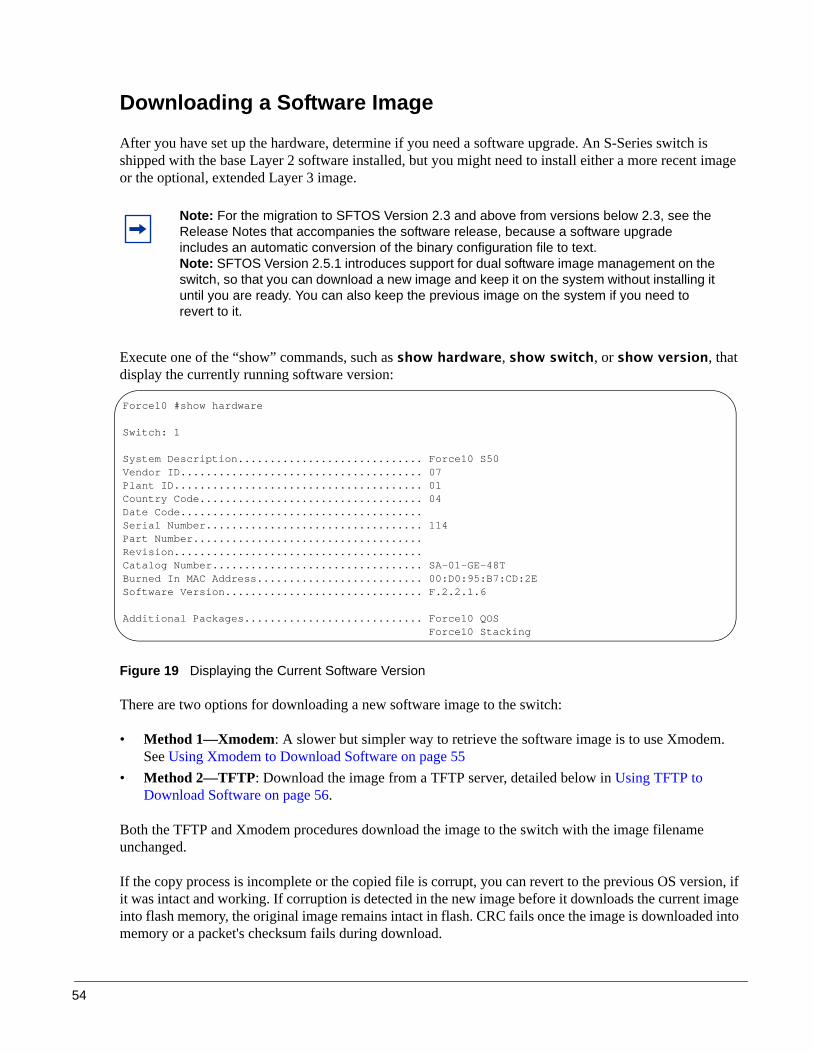
54
Downloading a Software Image
After you have set up the hardware, determine if you need a software upgrade. An S-Series switch is shipped with the base Layer 2 software installed, but you might need to install either a more recent image or the optional, extended Layer 3 image.
Execute one of the “show” commands, such as show hardware, show switch, or show version, that display the currently running software version:
Figure 19 Displaying the Current Software Version
There are two options for downloading a new software image to the switch:
• Method 1—Xmodem: A slower but simpler way to retrieve the software image is to use Xmodem. See Using Xmodem to Download Software on page 55
• Method 2—TFTP: Download the image from a TFTP server, detailed below in Using TFTP to Download Software on page 56.
Both the TFTP and Xmodem procedures download the image to the switch with the image filename unchanged.
If the copy process is incomplete or the copied file is corrupt, you can revert to the previous OS version, if it was intact and working. If corruption is detected in the new image before it downloads the current image into flash memory, the original image remains intact in flash. CRC fails once the image is downloaded into memory or a packet's checksum fails during download.
Note: For the migration to SFTOS Version 2.3 and above from versions below 2.3, see the Release Notes that accompanies the software release, because a software upgrade includes an automatic conversion of the binary configuration file to text.Note: SFTOS Version 2.5.1 introduces support for dual software image management on the switch, so that you can download a new image and keep it on the system without installing it until you are ready. You can also keep the previous image on the system if you need to revert to it.
Force10 #show hardware
Switch: 1
System Description............................. Force10 S50Vendor ID...................................... 07Plant ID....................................... 01Country Code................................... 04Date Code......................................Serial Number.................................. 114Part Number....................................Revision.......................................Catalog Number................................. SA-01-GE-48TBurned In MAC Address.......................... 00:D0:95:B7:CD:2ESoftware Version............................... F.2.2.1.6
Additional Packages............................ Force10 QOS Force10 Stacking

SFTOS Configuration Guide, Version 2.5.3.0 55
If the image gets corrupted in flash, the only recourse before SFTOS v. 2.5.1 was to download a new image using Xmodem, described next. After you install v. 2.5.1, which has support for on-board storage of two SFTOS images, it is easier to revert to the previous image.
Using Xmodem to Download Software
An alternative to using TFTP to upgrade the software image is to use the Xmodem protocol at the console port. You can use the copy xmodem command or the reload command, as used here:
1. From Privileged Exec mode, enter the command reload.
2. You then have 2 seconds to select option 2, as shown below in Figure 20 on page 55.
3. Then, from the boot menu, select 4 to choose the “XMODEM” option.
Or, typically, before starting the download, users want to increase the transfer rate to the maximum. So, instead of immediately selecting 4, you would select option 2, which accesses a menu that enables you to change the baud rate to 115200. Typically, you would then also need to modify your terminal software settings to 115200. After changing the terminal session rate to 1152000, and the connection is re-established, for example in Hyperterminal, press the ‘?’ key to refresh to the Boot Menu text.
Figure 20 Example of Launching the Boot Menu to select a Code Download through Xmodem
4. After selecting option 4 for an Xmodem software transfer, use the transfer sub-menu to browse the file system for the desired software image.
Force10 #reloadManagement switch has unsaved changes.Would you like to save them now? (y/n) n
Configuration Not Saved!Are you sure you want to reload the stack? (y/n) y
Reloading all switches.Force10 Boot Code...Version 01.00.26 06/03/2005
Select an option. If no selection in 2 seconds then operational code will start.
1 - Start operational code.2 - Start Boot Menu.Select (1, 2):2Boot Menu Version 30 Aug 2006 Options available1 - Start operational code2 - Change baud rate3 - Retrieve event log using XMODEM (64KB).4 - Load new operational code using XMODEM5 - Display operational code vital product data6 - Run flash diagnostics7 - Update boot code8 - Delete operational code9 - Reset the system10 - Restore Configuration to factory defaults (delete config files)11 - Activate Backup Image[Boot Menu] 4 “Activate Backup Image” new in v.2.5.1

56
5. After the transfer is complete, you can verify the current software image and save the running configuration (recommended), as described in the TFTP procedure (Using TFTP to Download Software on page 56). When you are ready to install the software, see Installing System Software on page 58.
Using TFTP to Download Software1. Using the CLI, gain access to the switch by logging in and issuing the enable command:
Figure 21 Logging In and Using the enable Command
2. Set the management IP address, subnet mask, and gateway address, as described in Setting the Management IP Address on page 47.
3. Make sure that you have a port enabled in the management VLAN. See Enabling Ports on page 46.
4. Ping the gateway to ensure access to the server from which to download the software image.
Figure 22 Using the ping Command
5. Ping the TFTP server from which you wish to download the software image:
Force10User:adminPassword:
NOTE: Enter '?' for Command Help. Command help displays all options that are valid for the 'normal' and 'no' command forms. For the syntax of a particular command form, please consult the documentation.
Force10 >enablePassword:
Force10 #ping 10.10.1.254
Send count=3, Receive count=3 from 10.16.1.254
Force10 #ping 10.16.1.56
Send count=3, Receive count=3 from 10.16.1.56

SFTOS Configuration Guide, Version 2.5.3.0 57
6. Download the sofware image by using the copy command:
Figure 23 Downloading New Software
With all versions of SFTOS, using the copy command to download SFTOS software to the management switch automatically propagates that software to all stack members. You also have the option of using the following version of the copy command to copy an image from the management unit to a stack member:
copy {image1 | image2} unit://unit/{image1 | image2}
For details on managing software in a stack of switches, see Upgrading Software in a Stack on page 112 in the Stacking chapter.
Saving the Running Configuration
After downloading new SFTOS software, and before installing it, consider the effect on your network configuration. If you have no interest in preserving the configuration, you can go ahead with the installation. See Installing System Software on page 58.
However, in most cases, you will want to save the current running configuration. The first step is to save it to NVRAM, which overwrites the startup configuration.
The easy way to do that is to enter, in Privileged Exec mode, the write command (no parameters; the command defaults to write memory.)
Force10 #copy tftp://10.16.1.56/f10r1v1m6.opr image1
Mode........................................... TFTPSet TFTP Server IP............................. 10.16.1.56TFTP Path...................................... ./TFTP Filename.................................. f10r1v1m6.oprData Type...................................... Code
Are you sure you want to start? (y/n) yTFTP code transfer startingTFTP receive complete... storing in Flash File System...
File transfer operation completed successfully.
Force10 #
The file name extension is either .opr or .bin, depending on the release.
Address of TFTP server Before v.2.5.1, the syntax for downloading an image was “system:image”.

58
An alternative is to use the copy command shown in Figure 24.
Figure 24 Saving the Current Running Configuration to NVRAM
In some cases, you must (or might want to) restore the configuration to factory defaults. This is typically recommended for upgrading from the Layer 2 Package to the Layer 3 Package, and is required when converting from the Layer 3 Package to the Layer 2 Package. See Restoring the System to the Factory Default Configuration on page 67. For more on managing configuration files, see Managing the Configuration on page 64.
After overwriting the startup configuration file with the running config, the second step in backing up the configuration is to save the startup configuration file to the network. See Saving the Startup Configuration to the Network on page 66.
Installing System Software
After downloading a new software image (see Downloading a Software Image on page 54) and backing up the configuration (see Saving the Running Configuration on page 57), you are ready to install the new software. Execute the reload command, as shown in Using the reload command to upgrade to SFTOS 2.5.1 on page 61.
Managing SFTOS Software with SFTOS Version 2.5.1
SFTOS v. 2.5.1 adds the Dual Image Management feature. It enables you to keep two SFTOS images on each stack member. Benefits include being able to revert easily to the previous SFTOS image if you discover that a newly installed image is problematic. It also enables you to defer installing the newly downloaded image through one or more reboots.
The copy command, when used to download a new SFTOS software image, propagates the software to all units in the stack. In addition, the copy command provides an option to manually copy an image to a selected stack member, typically a new member that does not yet have the software version that is set to be installed in the next reboot. For details, see Copying SFTOS Software to a Member Switch on page 113 in the Stacking chapter.
The reload [unit] command now provides selective rebooting of stack members. Combined with the ability in SFTOS 2.5.1 to select which software image is invoked in a reboot, you have various options in
Note: You can only save the running config to NVRAM (the running configuration cannot be directly saved to the network).
Force10 #copy system:running-config nvram:startup-config
This operation may take a few minutes.Management interfaces will not be available during this time.
Are you sure you want to save? (y/n) y
Configuration Saved!

SFTOS Configuration Guide, Version 2.5.3.0 59
choosing which software is launched in specific stack members. For example, you might choose to reboot a particular member without installing the new code copied to it.
SFTOS Version 2.5.1 provides several new or revised software management commands:
The syntax statements for the commands in the Dual Image Management feature are in the System Configuration chapter of the SFTOS Command Reference.
Command Syntax Command Mode Usage
boot system [unit] {image1 | image2}
Privileged Exec Activate a particular image on the target system (“activate”, here, means to identify, to the system, the software to install on the next reboot).
copy tftp://tftp_server_ip_address/path/filename {image1 | image2}
Privileged Exec The system image download command revised for SFTOS 2.5.1. (Previous to 2.5.1, the command was copy tftp://tftp_server_ip_address/path/filename system:image.)
copy {image1 | image2} unit://unit/{image1 | image2}
Privileged Exec Copy a selected software image from the management switch to selected switches.
delete [unit] {image1 | image2}
Privileged Exec Delete a specified software image.
filedescr [unit] {image1 | image2} text-description
Privileged Exec Adds a name to the image associated with “image1” or “image2”. The name shows up as the SNMP trap receiver name and in the output of the show bootvar command. The maximum length is 16 case-sensitive alphanumeric characters, with no spaces.
reload [unit] Privileged Exec Reboots the selected stack member. When unit is not specified, all stack members are rebooted.
show bootvar [unit] Privileged Exec Display version information and activation status for the current active and backup images on the specified stack member. If you do not specify a unit number, the command displays image details for all nodes on the stack.
update bootcode [unit] Privileged Exec Update the bootcode (boot loader) on the designated switch. (The bootcode is read from the active image for subsequent reboots).
Note: The following parameter definitions apply to the commands provided by the Dual Image Management feature:
• unit — the stack member number; only used for stacks. Not specifying a number causes all stack members to be affected by the command.
• image1 and image2 — the two possible stored software images. Use the copy command to set the association between a particular SFTOS file and the keywords image1 or image2.

60
Note that the association of a particular SFTOS file name with either “image1” or “image2” in the copy command, above, sets the association that is used by all other commands that use the image1 and image2 keywords.
For example, if the currently running software image is associated with image1, then you then download a new image as image1, a reload that boots image1 will boot that new image.
The Boot Menu is also revised in SFTOS v. 2.5.1 to allow the user to select either image from the boot menu (or also to download a replacement image). This choice is available in two cases:
• If the user interrupts the boot sequence• If the boot sequence fails to launch either saved software image. This can happen if the images become
corrupted (if the CRC check fails on the image).
When you are first installing SFTOS 2.5.1, you use the standard copy (see Downloading a Software Image on page 54), configuration backup (see Saving the Running Configuration on page 57), and reload commands (see Figure 25) that are common to all previous SFTOS versions. Note that the installation of v. 2.5.1 incurs a pause of several minutes while the switch reformats its flash to accommodate the Dual Image Management feature.
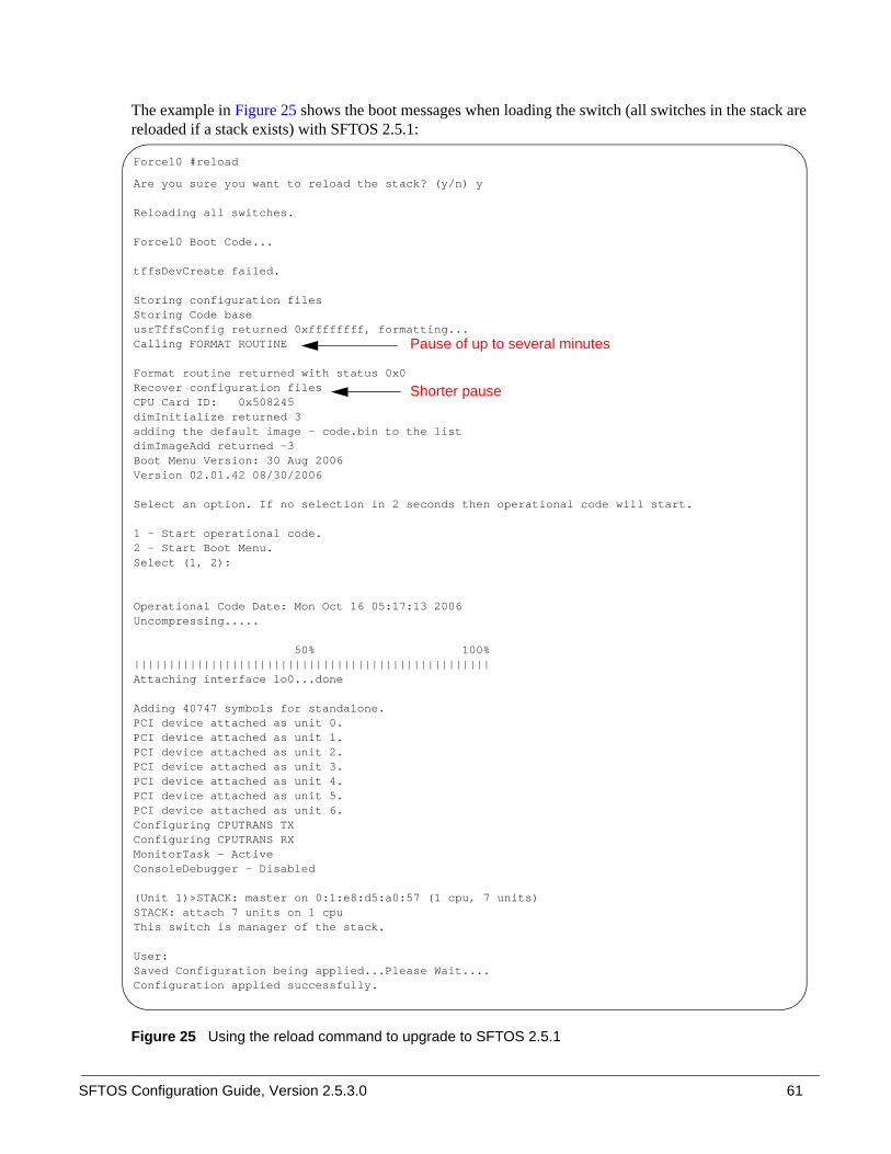
SFTOS Configuration Guide, Version 2.5.3.0 61
The example in Figure 25 shows the boot messages when loading the switch (all switches in the stack are reloaded if a stack exists) with SFTOS 2.5.1:
Figure 25 Using the reload command to upgrade to SFTOS 2.5.1
Force10 #reload
Are you sure you want to reload the stack? (y/n) y
Reloading all switches.
Force10 Boot Code...
tffsDevCreate failed.
Storing configuration filesStoring Code baseusrTffsConfig returned 0xffffffff, formatting...Calling FORMAT ROUTINE
Format routine returned with status 0x0Recover configuration files CPU Card ID: 0x508245dimInitialize returned 3adding the default image - code.bin to the listdimImageAdd returned -3Boot Menu Version: 30 Aug 2006Version 02.01.42 08/30/2006
Select an option. If no selection in 2 seconds then operational code will start.
1 - Start operational code.2 - Start Boot Menu.Select (1, 2):
Operational Code Date: Mon Oct 16 05:17:13 2006Uncompressing.....
50% 100%|||||||||||||||||||||||||||||||||||||||||||||||||||Attaching interface lo0...done
Adding 40747 symbols for standalone.PCI device attached as unit 0.PCI device attached as unit 1.PCI device attached as unit 2.PCI device attached as unit 3.PCI device attached as unit 4.PCI device attached as unit 5.PCI device attached as unit 6.Configuring CPUTRANS TXConfiguring CPUTRANS RXMonitorTask - ActiveConsoleDebugger - Disabled
(Unit 1)>STACK: master on 0:1:e8:d5:a0:57 (1 cpu, 7 units)STACK: attach 7 units on 1 cpuThis switch is manager of the stack.
User:Saved Configuration being applied...Please Wait....Configuration applied successfully.
Pause of up to several minutes
Shorter pause

62
After installing SFTOS 2.5.1 on the management switch and the stack, as described above, use the following procedure for subsequent upgrades:
Step Command SyntaxCommand Mode Purpose
1 show bootvar [unit] Privileged Exec (OPTIONAL) Display SFTOS version information and activation status on the specified stack member. If you do not specify a unit number, the command displays image details for all nodes on the stack.
2 copy {image1 | image2} unit://unit/{image1 | image2}
Privileged Exec (OPTIONAL) Copy a selected software image from the management switch to selected stack members. For details on managing software in a stack of switches, see Upgrading Software in a Stack on page 112in the Stacking chapter.
3 boot system [unit] {image1 | image2}
Privileged Exec Identify the image (image1 or image2) to install during the next reboot, on all stack members or only on the selected unit.
4 write Privileged Exec (OPTIONAL) Overwrite the startup configuration file with the running-config.
5 copy nvram:startup-config tftp://tftp_server_ip_address/path/filename
Privileged Exec (OPTIONAL) Copy the startup configuration file to network storage.
6 reload [unit] Privileged Exec Install the designated SFTOS software image (see Step 3) on all switches in the stack or on the selected unit. See Figure 26 on page 63.Caution: If you are converting from a Routing image to a Switching image, you must interrupt the reboot to revert the switch to factory defaults. See Restoring the System to the Factory Default Configuration on page 67.
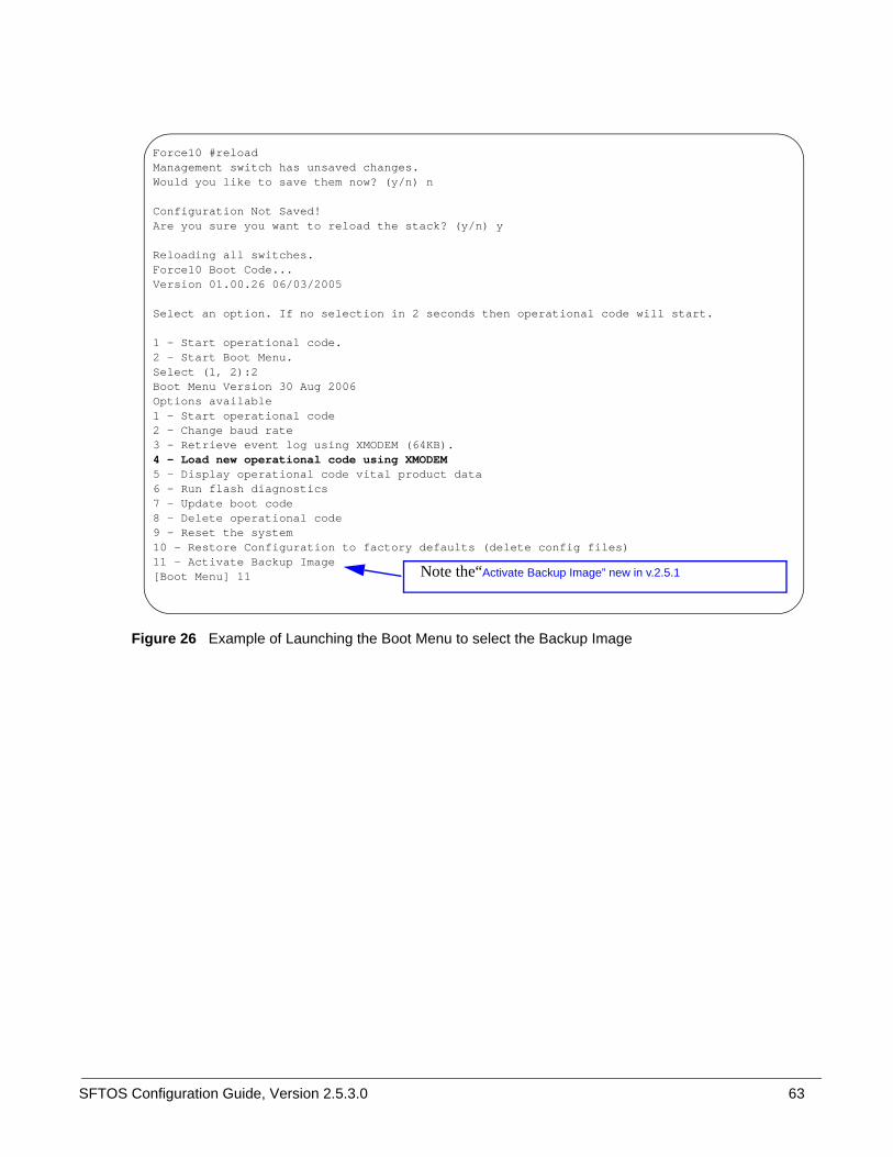
SFTOS Configuration Guide, Version 2.5.3.0 63
Figure 26 Example of Launching the Boot Menu to select the Backup Image
Force10 #reloadManagement switch has unsaved changes.Would you like to save them now? (y/n) n
Configuration Not Saved!Are you sure you want to reload the stack? (y/n) y
Reloading all switches.Force10 Boot Code...Version 01.00.26 06/03/2005
Select an option. If no selection in 2 seconds then operational code will start.
1 - Start operational code.2 - Start Boot Menu.Select (1, 2):2Boot Menu Version 30 Aug 2006 Options available1 - Start operational code2 - Change baud rate3 - Retrieve event log using XMODEM (64KB).4 - Load new operational code using XMODEM5 - Display operational code vital product data6 - Run flash diagnostics7 - Update boot code8 - Delete operational code9 - Reset the system10 - Restore Configuration to factory defaults (delete config files)11 - Activate Backup Image[Boot Menu] 11 Note the“Activate Backup Image” new in v.2.5.1

64
When converting from a Routing image to a Switching image, you must interrupt the reboot to revert the switch to factory defaults, as shown in Figure 27:
Figure 27 Restoring Factory Defaults when Converting from Routing to Switching Image
Managing the Configuration
This section contains the following major subsections, in this order:
• Clearing the Running Configuration on page 65• Saving the Startup Configuration to the Network on page 66• Configuring from the Network on page 66• Restoring the System to the Factory Default Configuration on page 67• Resetting the Pre-configured System on page 67
When the switch is booted, its configuration is managed by the startup configuration (“startup-config”) file that is stored in non-volatile memory (NVRAM). As you make configuration changes, those changes are stored in volatile system memory as the “running config” until you copy them to the startup-config. The quickest way to do that is to use the write memory command (executed from the Privileged Exec mode).
Force10 #reload
Management switch has unsaved changes.Would you like to save them now? (y/n) yConfiguration Saved!Are you sure you want to reload the stack? (y/n) y
Reloading all switches.
Force10 Boot Code...Version 01.00.26 06/03/2005
Select an option. If no selection in 2 seconds then operational code will start.
1 - Start operational code.2 - Start Boot Menu.Select (1, 2):2
Boot Menu Version 01.00.27 11/18/2005
Options available1 - Start operational code2 - Change baud rate3 - Retrieve event log using XMODEM (64KB).4 - Load new operational code using XMODEM5 - Display operational code vital product data6 - Update Boot Code7 - Delete operational code8 - Reset the system9 - Restore Configuration to factory defaults (delete config files)
[Boot Menu] 9 [Boot Menu] [Boot Menu] [Boot Menu] 8
Select 2 and press Enter within 2 seconds to invoke the Boot Menu.
Select 9 and press Enter.
Select 8 and press Enter.

SFTOS Configuration Guide, Version 2.5.3.0 65
You can also use the command copy system:running-config nvram:startup-config. For more detail, see Saving the Running Configuration on page 57.
Beginning with SFTOS Version 2.3, making changes to the startup-config file causes that file to be stored as a text file. A major benefit of that text file, in addition to faster reboots, is that you can edit the file after you copy it to a TFTP server. You can then download the edited file to any switch to use as the startup-config file.
Clearing the Running Configuration
When downloading the startup-config file to the system from a TFTP server, the file will not take effect as the startup configuration of the switch until a reboot (reload) is performed. However, you have the option of using the clear config command, followed by the script apply startup-config command to use the newly downloaded startup-config without rebooting the switch. For details in this chapter on using script commands, see Using Configuration Scripts on page 68.
The following example shows the clear config command for clearing the running-config from memory:
Figure 28 Clearing the Running Configuration
Caution: Beginning with Version 2.3, the following commands must be present and occur in the same relative locations in the startup-config file as if they had been automatically generated. Failure to do so will result in unpredictable behavior:
interface vlan vlan id vlan configuration commands exit configure stack member commands (for example member unit switchindex) exit
Force10 #clear configAre you sure you want to clear the configuration? (y/n)yClearing configuration. Please wait for login prompt.Force10 #(Unit 1)>

66
Saving the Startup Configuration to the Network
The following is an example of how to save the startup configuration to a TFTP site on the network.
Figure 29 Using the copy nvram:startup-config Command
Configuring from the Network
The following example is of installing a configuration file from the network. Starting with SFTOS v. 2.3, you can save a startup-config file as a text file to a server, edit it, and then download it to any switch.
Figure 30 Using the copy tftp Command to Download Startup-Config
Force10 #copy nvram:startup-config tftp://10.16.1.56/s50_1
Mode........................................... TFTPSet TFTP Server IP............................. 10.16.1.56TFTP Path...................................... ./TFTP Filename.................................. s50_1Data Type...................................... Config File
Are you sure you want to start? (y/n) y
File transfer operation completed successfully.
Force10 #copy tftp://10.16.1.56/s50_1 nvram:startup-config
Mode........................................... TFTPSet TFTP Server IP............................. 10.16.1.56TFTP Path...................................... ./TFTP Filename.................................. s50_1Data Type...................................... Config
Download configuration file. Current configuration will be cleared.
Are you sure you want to start? (y/n) yTFTP config transfer starting
TFTP download operation completed successfully.
Force10 #(Unit 1)>User:
You are now logged off

SFTOS Configuration Guide, Version 2.5.3.0 67
Restoring the System to the Factory Default Configuration
As discussed above in Clearing the Running Configuration on page 65, you can replace the running-config with the startup-config without rebooting the switch. However, if you have lost your CLI password, you might not be able to issue the necessary commands. In that case, you have the option of rebooting the switch with the factory default startup-config (recommended by TAC when upgrading from the Layer 2 Package to the Layer 3 Package, and required when converting from the Layer 3 to the Layer 2 image). To do so, use the following procedure:
1. If you have access to the CLI, use the reload command. Otherwise, remove and reinsert the power cord to power-cycle the switch.
2. When the system reboots, select 2 within two seconds to invoke the Boot Menu, as shown in Figure 31.
3. Select 10 to restore the configuration to factory defaults (deletes the configuration file).
4. Select option 9 to reload/boot the switch.
Figure 31 Restoring the Configuration to Factory Defaults
If you have previously backed up the running-config, you can download and reapply it. See Downloading and Uploading Files on page 52 or Configuring from the Network on page 66.
Resetting the Pre-configured System
If you are bringing up a system that had been previously configured in a stack, you must ensure the system is set to the correct unit number if installing into a new stack. If the system is not reconfigured to the correct unit number, it will come up as the switch number from the previous stack. For details, see
Note: Resetting to factory defaults is more powerful than executing the clear config command, because it resets all internal values.
Force10 Boot Code...Version 01.00.27 11/18/2005
Select an option. If no selection in 2 seconds then operational code will start.
1 - Start operational code.2 - Start Boot Menu.Select (1, 2):2
Boot Menu Version: 30 Aug 2006 Options available 1 - Start operational code 2 - Change baud rate 3 - Retrieve event log using XMODEM 4 - Load new operational code using XMODEM 5 - Display operational code vital product data 6 - Run flash diagnostics 7 - Update boot code 8 - Delete operational code 9 - Reset the system 10 - Restore configuration to factory defaults (delete config files) 11 - Activate Backup Image [Boot Menu] 9

68
Chapter 5, Stacking S-Series Switches. To ensure that the unit comes up with the correct unit number in the new stack, use the switch renumber command to change the unit number:
Using Configuration Scripts
This section contains:
• Creating a Configuration Script on page 68• Viewing a Configuration Script File on page 69• Uploading a Configuration Script to a TFTP Server on page 70• Deleting a Script on page 70• Downloading a Configuration Script from a TFTP Server on page 71• Applying a Configuration Script on page 72• Listing Configuration Scripts on page 74
Configuration scripts are ‘flat’ configuration files stored in the NVRAM. Their file names are appended with the “.scr” extension.
The configuration scripts are editable text files that can be uploaded and downloaded to and from the switch and a TFTP server.
See the Configuration Scripting section in the System Configuration chapter of the SFTOS Command Reference for details on all scripting commands.
Creating a Configuration Script
One way to create a “config script” is to use a variation of the show running-config command:
Command SyntaxCommand Mode Purpose
switch oldunit renumber newunit
Global Config
This command changes the switch identifier for a switch in the stack. The oldunit is the current switch identifier on the switch whose identifier is to be changed. The newunit is the updated value of the switch identifier.
Command Syntax Command Mode Purpose
show running-config <scriptname>.scr
Privileged Exec Create a configuration script by specific name.
Force10 #show running-config test.scr
Config script created successfully.

SFTOS Configuration Guide, Version 2.5.3.0 69
Viewing a Configuration Script File
To view the config script, use the script show scriptname.scr command.
Figure 32 Using the script show Command
Note: Starting with Release 2.3, you can use show running-config startup-config to achieve the same effect as you can with show running-config <scriptname>.scr. The resulting startup-config is a text file that you can save to a server and download to any switch.
Command Syntax Command Mode Purpose
script show scriptname.scr Privileged Exec To view a configuration script by specific name.
Force10 #script show test.scr
1 : !Current Configuration:2 : !3 : hostname "Force10"4 : network parms 10.10.1.33 255.255.255.0 10.10.1.2545 : interface vlan 116 : !System Description "Force10 S50"10 : !System Description F.5.6.2...

70
Uploading a Configuration Script to a TFTP Server
To upload a “config script” to a TFTP server, use the copy command.
Figure 33 Using the copy nvram:script Command
Deleting a Script
To delete a “config script”, use the script delete command.
Command Syntax Command Mode Purpose
copy nvram:script scriptname.scr tftp://x.x.x.x/scriptname.scr
Privileged Exec Copies the config script from the NVRAM to a TFTP server.
Command Syntax Command Mode Purpose
script delete <scriptname.scr> Privileged Exec Deletes the named script from the switch memory.
Force10 #copy nvram:script test.scr tftp://10.16.1.56/test.scr
Mode........................................... TFTPSet TFTP Server IP............................. 10.16.1.56TFTP Path......................................TFTP Filename.................................. test.scrData Type...................................... Config ScriptSource Filename................................ test.scr
Are you sure you want to start? (y/n) y
File transfer operation completed successfully.
Force10 #script delete test.scr
Are you sure you want to delete the configuration script(s)? (y/n)y
1 configuration script(s) deleted.
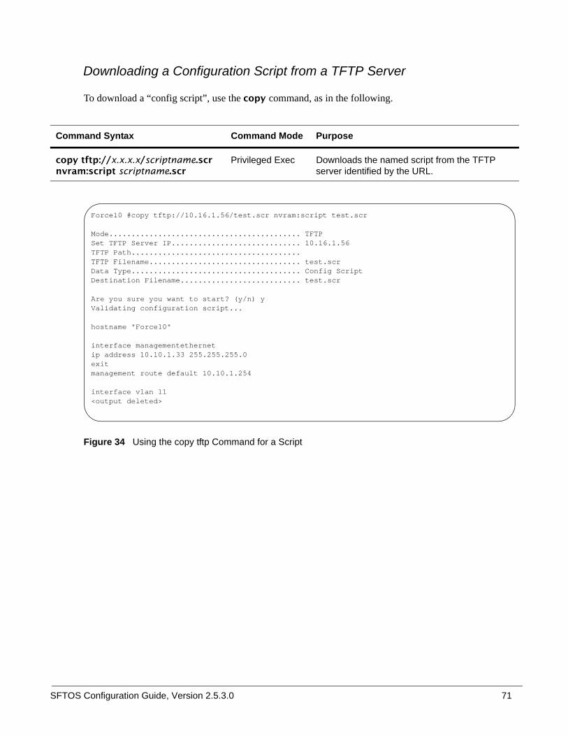
SFTOS Configuration Guide, Version 2.5.3.0 71
Downloading a Configuration Script from a TFTP Server
To download a “config script”, use the copy command, as in the following.
Figure 34 Using the copy tftp Command for a Script
Command Syntax Command Mode Purpose
copy tftp://x.x.x.x/scriptname.scr nvram:script scriptname.scr
Privileged Exec Downloads the named script from the TFTP server identified by the URL.
Force10 #copy tftp://10.16.1.56/test.scr nvram:script test.scr
Mode........................................... TFTPSet TFTP Server IP............................. 10.16.1.56TFTP Path......................................TFTP Filename.................................. test.scrData Type...................................... Config ScriptDestination Filename........................... test.scr
Are you sure you want to start? (y/n) yValidating configuration script...
hostname "Force10"
interface managementethernetip address 10.10.1.33 255.255.255.0 exitmanagement route default 10.10.1.254
interface vlan 11<output deleted>

72
Troubleshooting a Downloaded Script
While attempting to download a config script, the system validates the downloaded file. If the validation fails an error message like the following will appear:
Figure 35 Example of a Script Validation Error Message
Applying a Configuration ScriptTo apply a “config script”, use the script apply command, as in the following.
Figure 36 Using the script apply Command
Command Syntax Command Mode Purpose
script apply scriptname.scr Privileged Exec To do
Configuration script validation failed.Following lines in the script may have problem:Line 29:: permit 01:80:c2:00:00:00 any assign-queue 4Line 30:: permit any 01:80:c2:00:00:ff assign-queue 3 redirect 1/0/10Line 31:: permit 01:80:c2:00:00:ee any assign-queue 4Line 36:: match cos 5Line 44:: police-simple 500000 64 conform-action transmit violate-action dropLine 45:: police-simple 500000 64 conform-action transmit violate-action drop
Total error Lines :: 6The file being downloaded has potential problems. Do you want to save this file?
Force10 #script apply test.scr
Are you sure you want to apply the configuration script? (y/n)y
The system has unsaved changes.Would you like to save them now? (y/n) n
Configuration Not Saved!
hostname "Force10"
interface managementethernetip address 10.10.1.33 255.255.255.0 exitmanagement route default 10.10.1.254
interface vlan 11exitexitConfiguration script 'test.scr' applied.
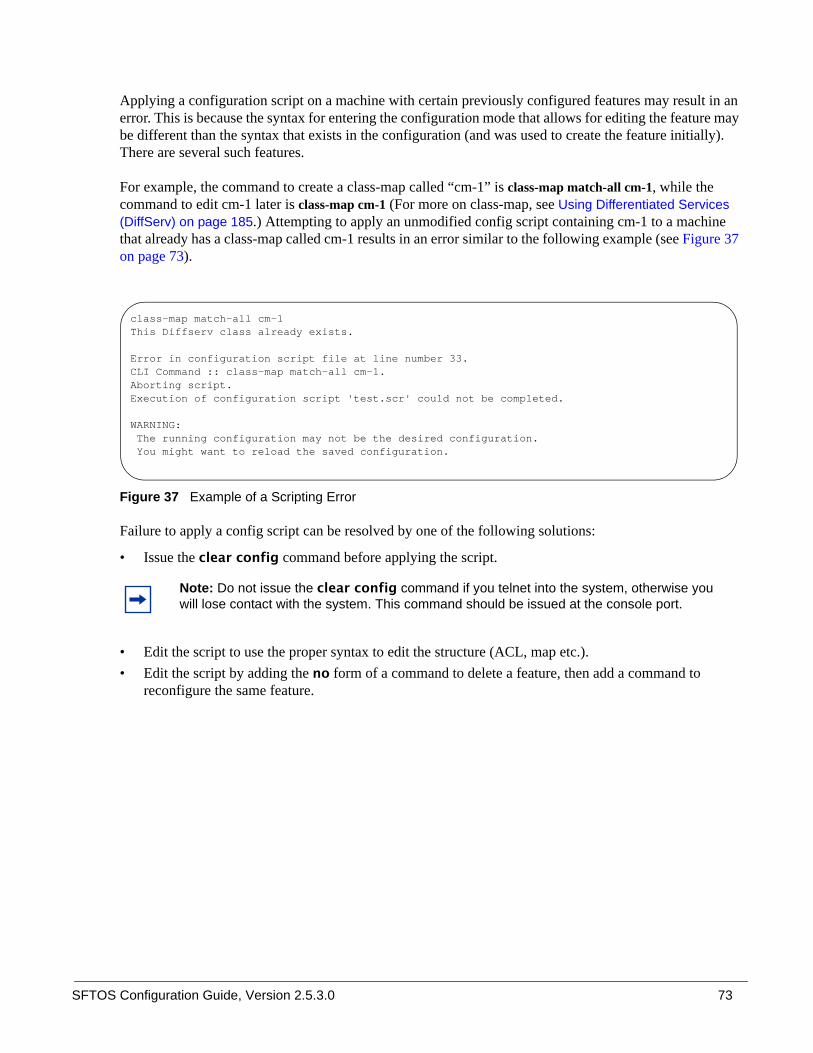
SFTOS Configuration Guide, Version 2.5.3.0 73
Applying a configuration script on a machine with certain previously configured features may result in an error. This is because the syntax for entering the configuration mode that allows for editing the feature may be different than the syntax that exists in the configuration (and was used to create the feature initially). There are several such features.
For example, the command to create a class-map called “cm-1” is class-map match-all cm-1, while the command to edit cm-1 later is class-map cm-1 (For more on class-map, see Using Differentiated Services (DiffServ) on page 185.) Attempting to apply an unmodified config script containing cm-1 to a machine that already has a class-map called cm-1 results in an error similar to the following example (see Figure 37 on page 73).
Figure 37 Example of a Scripting Error
Failure to apply a config script can be resolved by one of the following solutions:
• Issue the clear config command before applying the script.
• Edit the script to use the proper syntax to edit the structure (ACL, map etc.). • Edit the script by adding the no form of a command to delete a feature, then add a command to
reconfigure the same feature.
Note: Do not issue the clear config command if you telnet into the system, otherwise you will lose contact with the system. This command should be issued at the console port.
class-map match-all cm-1This Diffserv class already exists.
Error in configuration script file at line number 33.CLI Command :: class-map match-all cm-1.Aborting script.Execution of configuration script 'test.scr' could not be completed.
WARNING: The running configuration may not be the desired configuration. You might want to reload the saved configuration.

74
Listing Configuration Scripts
The script list command lists the configured scripts in a system:
Figure 38 Using the script list Command
Displaying LogsThe switch maintains four logs:
• Event log (“Persistent log”) — exception messages and critical boot-up messages; saved on switch reset— Use the command show eventlog.
• System log, “buffered log”) – system trace information; cleared on switch reset — Use the commands show logging or show logging history.
• List of logging hosts— Use the command show logging hosts.
• Traps – enabled trap events; cleared on switch reset — Use the command show logging traplogs.
For details on the logs and logging, see the chapter System Logs on page 91. See also the System Log chapter in the SFTOS Command Reference.
Force10 #script list
Configuration Script Name Size(Bytes)-------------------------------- -----------test.scr 2689
1 configuration script(s) found.2045 Kbytes free.
Force10 #

SFTOS Configuration Guide, Version 2.5.3.0 75
This chapter covers the following management tasks:
• Creating the Management IP Address• Changing the Management VLAN from the Default on page 76• Verifying Access to a Management Port on page 77• Verifying Management Port Connectivity on page 77• Setting Stack Management Preferences on page 77• Setting the Host Name Prompt on page 78• Restoring the Configuration to Factory Defaults on page 78• Setting up SNMP Management on page 80• Link Layer Discovery Protocol (LLDP) on page 83• Setting up Remote Network Monitoring (RMON) on page 83• Setting the System Date and Time on page 87• Gathering Details about the Switch on page 90
Creating the Management IP AddressThe procedure for creating the management IP address is introduced in Setting the Management IP Address on page 47 in the Getting Started chapter. Figure 39 shows the use of that procedure:
Figure 39 Creating the Management Port IP Address
Chapter 3 Management
Force10 (Config)#management route default 10.10.1.254Force10 (Config)#interface managementethernetForce10 (Config-if-ma)#ip address 10.10.1.251 255.255.255.0Force10 (Config-if-ma)#exitForce10 (Config)#exitForce10 #show interface managementethernetIP Address..................................... 10.10.1.151Subnet Mask.................................... 255.255.255.0Default Gateway................................ 10.10.1.254Burned In MAC Address.......................... 00:01:E8:D5:A0:39Locally Administered MAC Address............... 00:00:00:00:00:00MAC Address Type............................... Burned InNetwork Configuration Protocol Current......... NoneManagement VLAN ID............................. 1Web Mode....................................... DisableJava Mode...................................... Disable

76
Changing the Management VLAN from the DefaultAs stated in Setting Up the Management VLAN on page 50 in the Getting Started chapter, the default management VLAN is the default VLAN 1, so, when you configure the management IP interface (see Creating the Management IP Address on page 75), any port that is part of the default VLAN will carry management traffic.
On first startup, the default VLAN 1 includes every port (although, by default, all ports are shut down until you enable them—see Enabling Ports on page 46.) If you want to change the management VLAN from the default VLAN to another VLAN, create the new VLAN (see Creating a VLAN on page 50), and then use the following command sequence and example as your guide.
In the following example, we create and name VLAN 5, add one port to it (you can add more), and then designate the VLAN as the management VLAN.
Figure 40 Changing the Management VLAN from the Default
For more on VLANs, see Chapter 13, VLANs on page 215.
Step Command Syntax Command Mode Purpose
1 show vlan id vlan-id Privileged Exec Inspect the VLAN that you want to assign as the management VLAN.
2 interface managementethernet
Global Config Enter the Interface ManagementEthernet mode.
3 vlan participation vlan-id Interface ManagementEthernet
Select a VLAN to act as the management VLAN. The VLAN number, designated in vlan-id, must be from 1 to 3965. Note: If you set the management VLAN to a VLAN that does not exist, there is no error message.Note: This is the only mode in which you use the vlan participation command.
4 show interface managementethernet
Privileged Exec Verify the management VLAN and other management settings.
Force10 (Config)#interface vlan 5Force10 (conf-if-vl-5)#name management_vlanForce10 (conf-if-vl-5)#interface 1/0/43Force10 (conf-if-vl-5)#exitForce10 (Config)#interface managementethernetForce10 (Config-if-ma)#vlan participation 5Force10 (Config-if-ma)#exitForce10 (Config)#

SFTOS Configuration Guide, Version 2.5.3.0 77
Verifying Access to a Management PortIt is possible to set the management VLAN to a VLAN that does not exist. If you cannot reach anything from the management address, inspect the management VLAN with the commands show interface managementethernet or show running-config, to inspect the management IP settings, as shown in Figure 41.
Figure 41 Verifying Management Port Network
Verifying Management Port Connectivity
Figure 42 Verifying Management Port Connectivity
Setting Stack Management PreferencesFor details on combining S-Series switches into virtual single switches through stacking commands, see Chapter 5, Stacking S-Series Switches.
Note: For more on management access, see Protecting the Management Interface with a Loopback ACL on page 210.
Note: Each model in the S-Series line is only capable of stacking with other switches of the same model, and the S2410 models do not stack at all.
Force10 #show interface managementethernet
IP Address..................................... 192.168.0.50Subnet Mask.................................... 255.255.255.0Default Gateway................................ 192.168.0.11Burned In MAC Address.......................... 00:01:E8:0D:30:9ALocally Administered MAC Address............... 00:00:00:00:00:00MAC Address Type............................... Burned InNetwork Configuration Protocol Current......... NoneManagement VLAN ID............................. 5Web Mode....................................... DisableJava Mode...................................... Disable
Force10 #ping 192.168.0.100Send count=3, Receive count=3 from 192.168.0.100 Verify management port connectivity

78
Setting the Host Name PromptIf you have more than one individually managed S-Series switch, you can differentiate them by creating a unique CLI host name prompt for each switch. Use the hostname command, in Global Config mode, to edit the prompt, as shown in Figure 43:
Figure 43 Setting the Host Name
The host name is case-sensitive and can be up to 64 characters in length.
Restoring the Configuration to Factory Defaults
Restoring S-Series switches to the factory default settings is useful when:
• You upgrade from the Layer 2 Package (switching) to the Layer 3 Package (routing)• You lose the system passwords.• You want to remove an undesirable configuration.• The configuration has become very complex.• You want to move a switch from one network to another.
Before you reset the switch to factory defaults, consider backing up your configuration, which you can do through one of these means:
• Back up your configuration on a TFTP server.• Copy your configuration to a text file.• Copy the configuration locally on the flash memory device.
To reset an S-Series switch to factory defaults, you need access to the switch console through either a physical console or a Telnet connection.
Note: If you reset the switch to factory defaults while you access the switch by Telnet connection, you lose connectivity to the switch.
Note: When upgrading from SFTOS version 2.2.x to 2.3.x, you do not need to be concerned about manually reconfiguring the switch to use the new SFTOS version 2.3.x commands, because the upgrade process includes an automatic mapping of 2.2.x settings to 2.3.x expressions of those settings.
Force10 (Config)#hostname Force10_S50Force10_S50 (Config)#
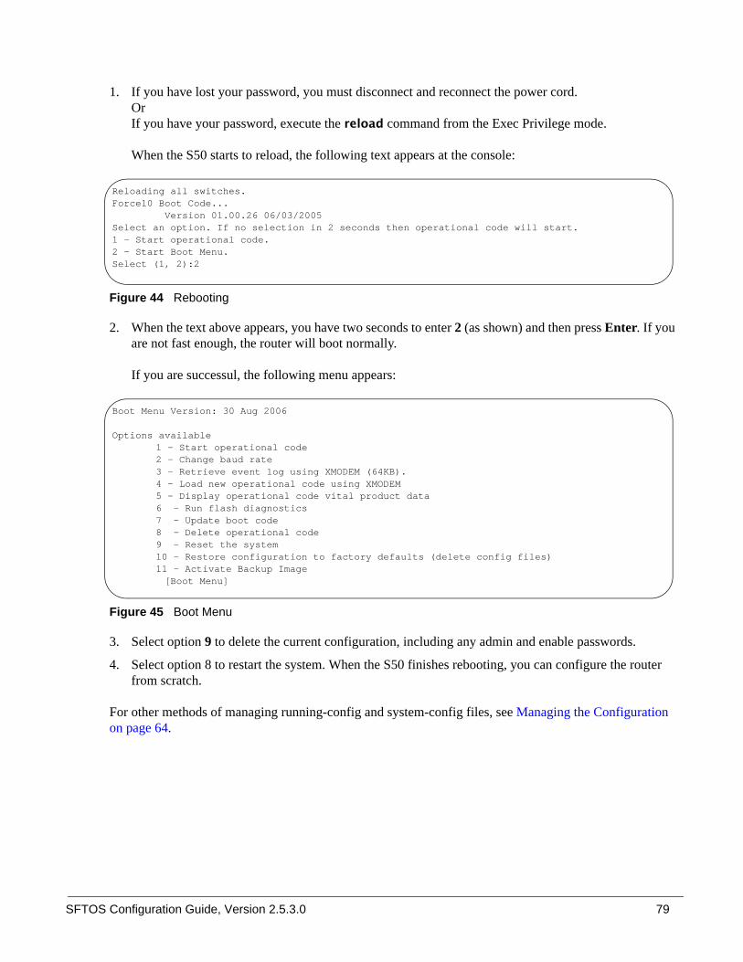
SFTOS Configuration Guide, Version 2.5.3.0 79
1. If you have lost your password, you must disconnect and reconnect the power cord. OrIf you have your password, execute the reload command from the Exec Privilege mode.
When the S50 starts to reload, the following text appears at the console:
Figure 44 Rebooting
2. When the text above appears, you have two seconds to enter 2 (as shown) and then press Enter. If you are not fast enough, the router will boot normally.
If you are successul, the following menu appears:
Figure 45 Boot Menu
3. Select option 9 to delete the current configuration, including any admin and enable passwords.
4. Select option 8 to restart the system. When the S50 finishes rebooting, you can configure the router from scratch.
For other methods of managing running-config and system-config files, see Managing the Configuration on page 64.
Reloading all switches.Force10 Boot Code... Version 01.00.26 06/03/2005Select an option. If no selection in 2 seconds then operational code will start.1 - Start operational code.2 - Start Boot Menu.Select (1, 2):2
Boot Menu Version: 30 Aug 2006 Options available
1 - Start operational code2 - Change baud rate3 - Retrieve event log using XMODEM (64KB).4 - Load new operational code using XMODEM5 - Display operational code vital product data6 - Run flash diagnostics 7 - Update boot code 8 - Delete operational code 9 - Reset the system 10 - Restore configuration to factory defaults (delete config files) 11 - Activate Backup Image
[Boot Menu]

80
Setting up SNMP ManagementSimple Network Management Protocol (SNMP) communicates management information between SNMP-based network management stations and SNMP agents in the switch. S-Series systems support SNMP versions 1, 2c, and 3, supporting both read-only and read-write modes. SFTOS sends SNMP traps, which are messages informing network management stations about the network.
SFTOS supports up to six simultaneous SNMP trap receivers. SFTOS does not support SNMP on VLANs.
SFTOS SNMP support conforms to RFC 1157 (SNMP v1), RFC 1213 (SNMP v2 (MIB-II)), and RFC 2570 (SNMP v3). For more on the MIBs and SNMP-related RFCs supported by SFTOS, refer to the SNMP appendix to this guide (see RFCs, MIBs, and Traps on page 313). That appendix also discusses the SNMP traps that SFTOS generates.
The MIB files are on the S-Series product CD-ROM and on the iSupport website (password required):https://www.force10networks.com/csportal20/KnowledgeBase/Documentation.aspx
As a best practice, Force10 Networks recommends polling several SNMP object IDs (OIDs), as described here. SNMP is especially valuable in certain cases — for example when a console connection is unavailable.
All MIBs listed in the output of the show sysinfo command for a particular SFTOS image can be polled. Specifically, the S50 supports counter MIBs, including the 32-bit and 64-bit IF-MIB and IP-MIB (accessing 64-bit counters requires SNMPv2c); hardware-related MIB variables, such as the Inventory MIB and Entity MIB; protocol-related MIBs, such as OSPF and VRRP; Layer 2 MIBs, such as the F10OS-SWITCHING-MIB; Layer 3 MIBs, such as F10OS-ROUTING-MIB, and the RMON MIB.
For general MIB queries, the OIDs start from 1.3.6.1.2.1. For private MIB queries, the OIDs start from 1.3.6.1.4.1.6027.1, where 6027 is the Force10 Enterprise Number.
This section provides basic configuration steps for enabling SNMP.
Command Syntax Command Mode Usage
interface managementethernet
Global Config Access the Interface Managementethernet mode in order to configure a management IP address, which is required for SNMP management . For details, see Setting up a Management Connection to the Switch on page 36.
[no] snmp-server community community-name
Global Config Identify an SNMP community for the switch to join. Force10 suggests that you use the same community name for all chassis that you will manage with your SNMP management system. If you have previously entered a string for another SNMP manager and agent, use the existing string.
[no] snmptrap name ipaddr Global Config Adds an SNMP trap receiver name and IP address to the SNMP community. The maximum name length is 16 case-sensitive alphanumeric characters.

SFTOS Configuration Guide, Version 2.5.3.0 81
Other commands that configure the SNMP server connection include:
• snmp-server: Sets the name and the physical location of the switch, and the organization responsible for the network.
• snmp-server community ipaddr: Sets a client IP address for an SNMP community.• snmp-server community ipmask: Sets a client IP mask for an SNMP community.• [no] snmp-server community mode name: Activates [deactivates] the designated SNMP
community. All configured communities are enabled by default.• snmp-server community ro: Restricts access to switch information to read-only.• snmp-server community rw: Sets access to switch information to read/write.• snmptrap ipaddr: Assigns an IP address to a specified community name.• [no] snmptrap mode: Activates [deactivates] an SNMP trap receiver name.
In Privileged Exec mode:
• To view the SNMP configuration, use the show snmpcommunity command. • To display SNMP trap receiver entries, use the show snmptrap command.
See also Link Layer Discovery Protocol (LLDP) on page 83.
Managing SNMP Traps
SNMP trap events are logged and sent out via SNMP. For trap management, use the CLI commands listed below.
Traps can be enabled for the following features:
• Authentication• Link up/down • Multiple users• Spanning Tree• OSPF• DVMRP• PIM (both DM and SM with one command)
[no] snmp-server enable trap violation
Interface Config or Interface Range
Optionally, enable the sending of new violation traps for a specified interface designating when a packet with a disallowed MAC address is received on a locked port. Except for this trap, all traps are enabled by default. For details on trap options, see Managing SNMP Traps on page 81, below.
Note: The DVMRP, OSPF, and PIM traps and associated commands are supported only in the Layer 3 software image of SFTOS.
Command Syntax Command Mode Usage
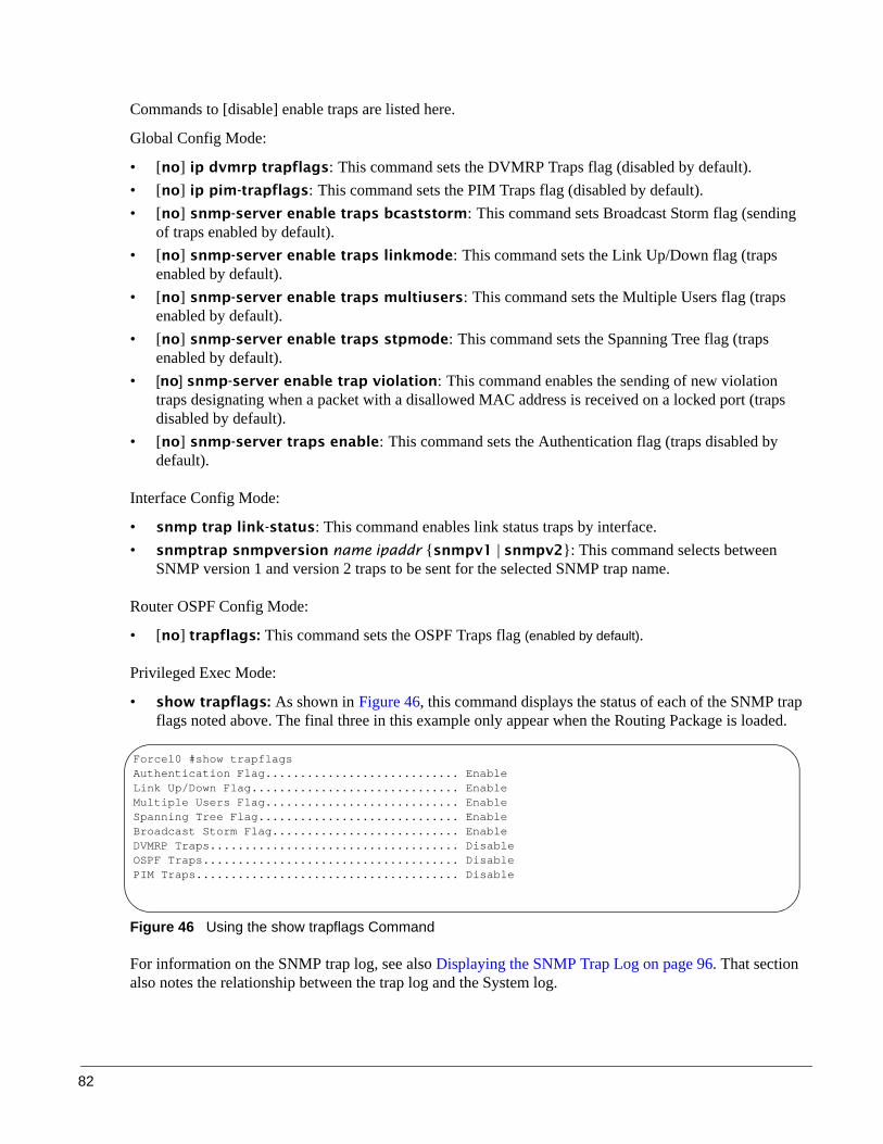
82
Commands to [disable] enable traps are listed here.
Global Config Mode:
• [no] ip dvmrp trapflags: This command sets the DVMRP Traps flag (disabled by default).• [no] ip pim-trapflags: This command sets the PIM Traps flag (disabled by default).• [no] snmp-server enable traps bcaststorm: This command sets Broadcast Storm flag (sending
of traps enabled by default).• [no] snmp-server enable traps linkmode: This command sets the Link Up/Down flag (traps
enabled by default).• [no] snmp-server enable traps multiusers: This command sets the Multiple Users flag (traps
enabled by default).• [no] snmp-server enable traps stpmode: This command sets the Spanning Tree flag (traps
enabled by default).• [no] snmp-server enable trap violation: This command enables the sending of new violation
traps designating when a packet with a disallowed MAC address is received on a locked port (traps disabled by default).
• [no] snmp-server traps enable: This command sets the Authentication flag (traps disabled by default).
Interface Config Mode:
• snmp trap link-status: This command enables link status traps by interface.• snmptrap snmpversion name ipaddr {snmpv1 | snmpv2}: This command selects between
SNMP version 1 and version 2 traps to be sent for the selected SNMP trap name.
Router OSPF Config Mode:
• [no] trapflags: This command sets the OSPF Traps flag (enabled by default).
Privileged Exec Mode:
• show trapflags: As shown in Figure 46, this command displays the status of each of the SNMP trap flags noted above. The final three in this example only appear when the Routing Package is loaded.
Figure 46 Using the show trapflags Command
For information on the SNMP trap log, see also Displaying the SNMP Trap Log on page 96. That section also notes the relationship between the trap log and the System log.
Force10 #show trapflagsAuthentication Flag............................ EnableLink Up/Down Flag.............................. EnableMultiple Users Flag............................ EnableSpanning Tree Flag............................. EnableBroadcast Storm Flag........................... EnableDVMRP Traps.................................... DisableOSPF Traps..................................... DisablePIM Traps...................................... Disable

SFTOS Configuration Guide, Version 2.5.3.0 83
For information on S-Series SNMP traps, MIBs, and SNMP-related RFCs, see RFCs, MIBs, and Traps on page 313. See also the techtip “What Should I Poll with SNMP?” on the iSupport website:https://www.force10networks.com/csportal20/KnowledgeBase/ToolTipsSSeries.aspx
For more on SNMP commands, see the SNMP Community Commands section in the Management chapter of the SFTOS Command Reference.
Link Layer Discovery Protocol (LLDP)The IEEE 802.1AB standard defines the Link Layer Discovery Protocol (LLDP). This protocol allows a switch residing on an 802 VLAN to advertise connectivity, physical description, management information, and major capabilities. The information distributed via this protocol is stored by its recipients in a standard Management Information Base (MIB), facilitating multi-vendor interoperability and use of standard management tools to discover and make available physical topology information for network management. The command set includes:
• Configure LLDP globally (Global Config mode):— [no] lldp {[mode {tx | rx | both}] [hello seconds] [multiplier integer]}
Enter either mode, hello, or multiplier, followed by a value for the associated variable.
• Configure LLDP on a single port (timers not supported on one interface) (Interface Config mode):— [no] lldp mode {tx | rx | both}
• Display LLDP information (Privileged Config mode):
show lldp interface [all | interface unit/slot/port]
show lldp local-device [all | interface unit/slot/port]
show lldp neighbors [all | interface unit/slot/port]
show lldp remote-device [all | interface unit/slot/port]
• Clear LLDP information (Global Config mode):
clear lldp neighbors [interface unit/slot/port]
clear lldp counters [interface unit/slot/port]
Setting up Remote Network Monitoring (RMON)Remote Network Monitoring (RMON) in SFTOS is based on industry RMON RFC standards, providing both 32-bit and 64-bit monitoring of S-Series switches, along with long-term statistics collection.
Note: SFTOS supports the RMON (Remote Network Monitoring) MIB (RFC 2819), which is enabled by default and cannot be disabled. SFTOS contains no commands for configuring RMON or displaying RMON data. For more on RMON support, see the RMON techtip on iSupport, or see the RMON MIB file, which is on both the S-Series product CD and iSupport.
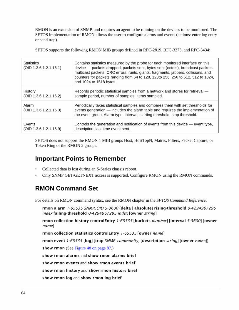
84
RMON is an extension of SNMP, and requires an agent to be running on the devices to be monitored. The SFTOS implementation of RMON allows the user to configure alarms and events (actions: enter log entry or send trap).
SFTOS supports the following RMON MIB groups defined in RFC-2819, RFC-3273, and RFC-3434:
SFTOS does not support the RMON 1 MIB groups Host, HostTopN, Matrix, Filters, Packet Capture, or Token Ring or the RMON 2 groups.
Important Points to Remember• Collected data is lost during an S-Series chassis reboot.• Only SNMP GET/GETNEXT access is supported. Configure RMON using the RMON commands.
RMON Command Set
For details on RMON command syntax, see the RMON chapter in the SFTOS Command Reference.
rmon alarm 1-65535 SNMP_OID 5-3600 {delta | absolute} rising-threshold 0-4294967295 index falling-threshold 0-4294967295 index [owner string]
rmon collection history controlEntry 1-65535 [buckets number] [interval 5-3600] [owner name]
rmon collection statistics controlEntry 1-65535 [owner name]
rmon event 1-65535 [log] [trap SNMP_community] [description string] [owner name])
show rmon (See Figure 48 on page 87.)
show rmon alarms and show rmon alarms brief
show rmon events and show rmon events brief
show rmon history and show rmon history brief
show rmon log and show rmon log brief
Statistics (OID 1.3.6.1.2.1.16.1)
Contains statistics measured by the probe for each monitored interface on this device — packets dropped, packets sent, bytes sent (octets), broadcast packets, multicast packets, CRC errors, runts, giants, fragments, jabbers, collisions, and counters for packets ranging from 64 to 128, 128to 256, 256 to 512, 512 to 1024, and 1024 to 1518 bytes.
History (OID 1.3.6.1.2.1.16.2)
Records periodic statistical samples from a network and stores for retrieval — sample period, number of samples, items sampled.
Alarm (OID 1.3.6.1.2.1.16.3)
Periodically takes statistical samples and compares them with set thresholds for events generation — includes the alarm table and requires the implementation of the event group. Alarm type, interval, starting threshold, stop threshold.
Events (OID 1.3.6.1.2.1.16.9)
Controls the generation and notification of events from this device — event type, description, last time event sent.

SFTOS Configuration Guide, Version 2.5.3.0 85
show rmon statistics and show rmon statistics brief
Configuring RMON Alarms
The following steps create an RMON event ID and associates an alarm to it. The example (see Figure 48 on page 87) following it shows the use of these commands.
The event variables are:
• 1-65535: An arbitrary number to be used to refer to this event in the Index• log: Create an entry in the log table. Default none• trap:SNMP community used if a trap is to be sent (default: public)• description: Comment describing this entry, <string-max 127 char >• owner: Entity that configured this entry, <string-max 127 char>
Step Command Syntax Command Mode Purpose
1 rmon event 1-65535 [log] [trap SNMP_community] [description string][owner name]
Global Config Add an event ID to the RMON Event Table.
2 [no] rmon alarm 1-65535 SNMP_OID 5-3600 {delta | absolute} rising-threshold 0-4294967295 index falling-threshold 0-4294967295 index [owner string]
Global Config Identify the event ID created in Step 1 for which you want to set [or disable] an alarm, identify the target MIB, and configure the parameters that trigger the alarm.
3 show rmon alarms brief Privileged Exec Display a summary of the contents of the RMON Alarm Table.

86
Figure 47 RMON Event Thresholds
Figure 47, above, depicts the points at which RMON threshold alarms are triggered. The first concept is that an event occurs when a threshold is crossed — either crossing a rising threshold or crossing a falling threshold. The other main concept is that a second event of that type cannot occur until the opposite threshold has been crossed in order to end the period of the first event.
In setting the alarm, you must choose between absolute and delta:
• absolute — This is an actual value of the selected MIB variable. This choice is better for rate measurements that vary plus or minus. For example, if a value never falls, the falling threshold will never be reached, and the rising threshold will only be crossed once.
• delta — This choice is best with counters that only increment. The previous value of the MIB variable is subtracted from the current value to determine whether the value is incrementing from its previous value by the Rising Threshold amount, or by an amount equal to or less than the Falling Threshold amount.

SFTOS Configuration Guide, Version 2.5.3.0 87
Example of configuring an RMON alarm
The following example shows the use of the rmon event and rmon alarm commands to create two event IDs and then associate them with an alarm. The event IDs are highlighted in the alarm statement.
Figure 48 Configuring an RMON Alarm
Setting the System Date and TimeThis section describes how to configure the date and time on the switch. The date and time are used for synchronizing network resources, particularly the timestamps in logs (see System Logs on page 91).
You have the option of using the Simple Network Time Protocol (SNTP) feature or simply setting the clock (both date and time) manually. Once set, the clock updates automatically through a system reboot or shutdown.
This section contains the following major sub-sections:
• Setting the System Date and Time Manually• SNTP Overview• CLI Examples of SNTP Setup on page 89
Note: Setting the timezone is not supported.
Force10# configForce10 (config)#rmon event 10Force10 (config)#rmon event 20Force10 (config)#rmon alarm 50 1.3.6.1.4.1.6027.1.1.16.0.2 absolute rising-threshold 200 10 falling-threshold 100 20Force10 (config)#exitForce10# show rmon
RMON statusTotal memory used ..................... 202260 bytes.Ether statistics table ................ 2 entries, 1184 bytesEther history table ................... 9 entries, 198876 bytesAlarm table ........................... 2 entries, 536 bytesEvent table ........................... 4 entries, 1664 bytesLog table ............................. 0 entries, 0 bytesForce10#

88
Setting the System Date and Time Manually
Use the clock time {dd/mm/yyyy | hh:mm:ss} command in Global Config mode to set the software clock. Enter either the date in dd/mm/yyyy format (for example, 10/01/2007 for October 1, 2007) or the time in hh:mm:ss format (for example, 22:45:00, for 10:45 P.M.). If you enter only one parameter (either date or time), while leaving the other parameter unchanged, the unchanged parameter continues to be based on the previous command execution.
The software clock runs only when the software is up. When the switch reboots, the clock restarts, based on the hardware clock. If you set the date and time manually, and then set up SNTP, the automatic update uses the SNTP update.
Use the show clock command to check the accuracy of the system date and time.
SNTP Overview
SNTP:
• Is an adaptation of NTP• Provides a synchronized network timestamp• Can be used in broadcast or unicast mode• Client is implemented over UDP, which listens on port 123
The SNTP command set consists of:
• sntp broadcast client poll-interval poll-interval: Set the poll interval for SNTP broadcast clients in seconds as a power of two, with a range from 6 to 16.
• sntp client mode [broadcast | unicast]: Enable SNTP client mode and, optionally, set the mode to either broadcast or unicast.
• sntp client port port-ID [poll-interval]: Set the SNTP client port ID to a value from 1 to 65535. Then, optionally, set the poll interval for that client in seconds, as a power of two, in the range from 6 to 10.
• sntp unicast client poll-interval poll-interval: Set the poll interval for SNTP unicast clients in seconds as a power of two, with a range from 6 to 16.
• sntp unicast client poll-timeout timeout: Set the poll timeout for SNTP unicast clients in seconds to a value from 1-30.
• sntp unicast client poll-retry: Set the poll retry for SNTP unicast clients to a value from 0 to 10.• sntp server: Configure an SNTP server (maximum of three).• show sntp: Display SNTP settings and status.• show sntp client: Display SNTP client settings.• show sntp server: Display SNTP server settings and configured servers.

SFTOS Configuration Guide, Version 2.5.3.0 89
CLI Examples of SNTP Setup
The following examples show the major command sequences in configuring the SNTP connection.
Example #1: Configuring SNTP client mode
Figure 49 Configuring SNTP Client Mode
Example #2: Configuring SNTP client port
Figure 50 Configuring the SNTP Client Port
Example #3: Configuring SNTP server
Figure 51 Configuring the SNTP Server Connection
Example #4: show sntp client
Figure 52 Using the show sntp client Command
Force10 (Config)#sntp client mode broadcast ?<cr> Press Enter to execute the command.Force10 (Config)#sntp client mode unicast ?<cr> Press Enter to execute the command.Force10 (Config)#sntp broadcast client poll-interval ?<6-10> Enter value in the range (6 to 10). Poll interval is 2^(value) in seconds.
Force10 (Config) #sntp client port 1 ?<cr> Press Enter to execute the command.<6-10> Enter value in the range (6 to 10). Poll interval is 2^(value) in seconds.
Force10(Config) #sntp server 10.11.8.6 ?<cr> Press Enter to execute the command.<1-3> Enter SNTP server priority from 1 to 3.
Force10 #show sntp clientClient Supported Modes: unicast broadcastSNTP Version: 4Port: 123Client Mode: unicastUnicast Poll Interval: 6Poll Timeout (seconds): 5Poll Retry: 1

90
Example #5: show sntp server
Figure 53 Using the show sntp server Command
Gathering Details about the SwitchIn addition to the show commands demonstrated in this chapter, the section Verifying Details about the Switch on page 41 in the Getting Started chapter contains a good summary of show commands useful for gathering typical switch information. See also the section Using show Commands for Stacking Information on page 116 in the Stacking chapter.
Force10 #show sntp serverServer IP Address: 10.11.8.6Server Type: ipv4Server Stratum: 3Server Reference Id: NTP Srv: 128.4.1.2Server Mode: ServerServer Maximum Entries: 3Server Current Entries: 1SNTP Servers------------IP Address: 10.11.8.6 Address Type: IPV4Priority: 1Version: 4Port: 123Last Update Time: JUNE 18 04:59:13 2005Last Attempt Time: JUNE 18 11:59:33 2005Last Update Status: OtherTotal Unicast Requests: 1111Failed Unicast Requests: 361
SFTOS Configuration Guide, Version 2.5.3.0 91
This chapter describes the system logging features, in these major sections:
• Logging Commands on page 91• Configuring the System Log on page 92• Using the Persistent Event Log on page 95• Displaying the SNMP Trap Log on page 96• Configuring Syslog Server Host Connections on page 97
The S-Series switch maintains five logs:
• System log: This log, also referred to as the buffered log, collects events down to the level of “critical” (by default). The log is stored in RAM until it is lost at power off or reboot. Thus, as a best practice, you should save these messages to a syslog server. The System log does not run by default, so you must enable it, at which time you can also set the level of detail to collect. See Configuring the System Log on page 92 and Displaying the System Log on page 93.
• SFTOS logging history table: This table is another internal place to store system messages. Use the logging history command to configure the log, and the show logging history command to display the log.
• Event log: This log, also referred to as the persistent log, collects exception messages and critical boot-up messages. The log is enabled by default, stored in flash memory, and is not lost upon system reboot or failover in a stack. SFTOS reserves 16 MB for the event log. See Using the Persistent Event Log on page 95.
• Trap log: This log collects SNMP traps. For details, see Displaying the SNMP Trap Log on page 96.• List of logging hosts: Use the command show logging hosts. For details, see Configuring Syslog
Server Host Connections on page 97.
Logging CommandsThe Syslog chapter in the SFTOS Command Reference provides a detailed command syntax for the system log command set, which consists of the following commands:
• logging buffered. See Configuring the System Log on page 92.• logging buffered wrap. See Configuring the System Log on page 92.• logging cli-command. See Configuring the System Log on page 92.• logging console. See Configuring the System Log on page 92.• logging facility. See Configuring Syslog Server Host Connections on page 97.
Chapter 4 System Logs

92
• logging history. See Configuring the System Log on page 92.• logging host. See Configuring Syslog Server Host Connections on page 97.• logging host reconfigure. See Configuring Syslog Server Host Connections on page 97.• logging host remove. See Configuring Syslog Server Host Connections on page 97.• logging syslog. See Configuring Syslog Server Host Connections on page 97.• show eventlog. See Using the Persistent Event Log on page 95.• show logging. See Displaying the System Log on page 93.• show logging history. See Displaying the System Log on page 93.• show logging hosts. See Configuring Syslog Server Host Connections on page 97.• show logging traplogs. See Displaying the SNMP Trap Log on page 96.
Configuring the System LogBy default, buffered logging (the “System log”) is disabled. To enable the system logging:
Note: See also the show trapflags and show snmptrap commands in the Management chapters of this guide and the SFTOS Command Reference.
Command Syntax Command Mode Purpose
logging buffered Global Config Turn on buffered logging (off by default). Enter no logging buffered to disable buffered logging.
no logging buffered wrap Global Config (Optional) Turn off wrapping (overwriting the oldest events). The feature, enabled by default, allows continued logging when memory capacity is reached. Enter logging buffered wrap to reenable wrapping.
no logging cli-command Global Config (Optional) The logging of CLI activity is enabled by default. To turn this feature off, enter this command. Enter logging cli-command to reenable logging of CLI commands.
logging console [severitylevel]
Global Config (Optional) Enable logging to the console (disabled by default). The default logging severity level is 2 (critical). To change the level, enter the appropriate word or equivalent integer value in place of severitylevel, as listed here: emergency (0), alert (1), critical (2), error (3), warning (4), notice (5), informational (6), debug (7). Note: The severity level entered here does not affect the severity level of the system log stored in memory; that severity level is fixed at 7 (debug).Enter no logging console to disable console logging.

SFTOS Configuration Guide, Version 2.5.3.0 93
Displaying the System Log
As shown in Figure 54, execute the show logging command to see the System log messages that you configured in logging buffered, above:
Figure 54 Using the show logging Command
You also have the option of using the show logging history command to view system messages through the SFTOS logging history table, which you configured, above, with the logging history command.
logging history size size Global Config Specify how many messages are to be saved in the SFTOS logging history table before being overwritten. This log collects the same messages as the System log.
See Configuring Syslog Server Host Connections on page 97.(Optional) To display accurate times and dates in the log, configure a connection to an SNTP server. See Setting the System Date and Time Manually on page 88.
Note: You can copy the System log from the switch to a TFTP server. See Downloading and Uploading Files on page 52 in the Getting Started chapter.
Command Syntax Command Mode Purpose
Force10 #show logging ?
<cr> Display buffered (in-memory) log entries.<1-128> Number of buffered log entries to be displayed.history Display the contents of syslog history table.hosts Display logging hosts.traplogs Display Trap Records.
Force10 #show logging
Syslog Logging : enabledCLI Command Logging : disabledConsole Logging : level alertBuffered (In-Memory) Logging : level informational, 67 Messages LoggedBuffered Logging Wrapping Behavior : OnLogging Host List Empty
<189> JAN 01 00:00:58 0.0.0.0-1 TRAPMGR[190295576]: traputil.c(661) 67 %% Cold Start: Unit: 0<190> JAN 01 00:00:38 0.0.0.0-1 UNKN[137768456]: sysapi.c(1707) 66 %% Building defaults for file lldpCfgData.cfg version 1<190> JAN 01 00:00:37 0.0.0.0-1 UNKN[213988280]: sysapi.c(1707) 65 %% Building defaults for file qos_cos.cfg version 2<190> JAN 01 00:00:37 0.0.0.0-1 UNKN[159744808]: sysapi.c(1707) 64 %% Building defaults for file ipStaticArpCfg.cfg version 2<190> JAN 01 00:00:37 0.0.0.0-1 UNKN[213988280]: sysapi.c(1707) 63 %% Building defaults for file acl.cfg version 5<189> JAN 01 17:03:45 192.168.11.50-1 TRAPMGR[194961512]: traputil.c(661) 273 %% Link Up: LAG- 2

94
Interpreting system log messagesTable 2 uses the first log message in Figure 54 as an example to present the field descriptions:
<189> JAN 01 00:00:58 0.0.0.0-1 TRAPMGR[190295576]: traputil.c(661) 67 %% Cold Start: Unit: 0 Table 2 A System Log Message Decomposed
Field Example Description
<189> The leftmost column displays a combination of the facility and the severity. Divide the number in angle brackets by 8 to arrive at the facility. The remainder is the severity (per RFC 3164). In this example, the <189> displayed in the leftmost column divided by 8 yields a remainder/severity of 5.If you do not set the facility option, the severity levels display clearly in that field: • 0 = emergency• 1 = alert• 2 = critical• 3 = error• 4 = warning• 5 = notice• 6 = informational• 7 = debug
JAN 01 00:00:058 Timestamp
0.0.0.0-1 Stack ID (If this unit were #2 in a stack, the Stack ID would be 0.0.0.0-2.)
TRAPMGR Software component name (“UNKN” in the following messages = unknown)
[190295576]: Thread ID in software component
traputil.c Software file name
(661) Line number in software file identified in software file name
12 Event log message sequence number
%% Cold Start: Unit: 0 Event message

SFTOS Configuration Guide, Version 2.5.3.0 95
Using the Persistent Event LogIn addition to the optional buffered System log described above, the switch maintains a persistent Event log in NVRAM. Persistent logging is always enabled to memory and disabled to the console or to syslog servers. The log does not require configuration.
The purpose of the Event log is to save system exception information to persistent memory for analysis by Force10 Engineering. Error messages start with “ERROR”, while event messages start with “EVENT”, as shown in Figure 55.
Execute the show eventlog command (with no keyword), as shown in Figure 55, below.
Figure 55 Using the show eventlog Command
Because the show eventlog command monitors a persistent log database, it is important to correlate any ERROR entries with the timeline using the time designator. The Time column in the output is the system up-time, shown by number of days (“d”), hours (“h”), minutes (“m”), and seconds (“s”).
Although the structure of the System log and Event log are different, both logs contain the same software file, line, and task information. For example, a reboot is a common event, indicated in each log by “bootos.c”. All “bootos.c” entries should be between 8 to 15 seconds after the system restarts, which you can see in the Time column in Figure 55. The typical log entry following a “bootos.c” entry is either:
• “ERROR> unitmgr.c”: Indicates the system rebooted due to a user command. • “ERROR> reset603.c”: Indicates the system rebooted due to a program error interrupt. • “ERROR> broad_hpc_drv.c”: Typically indicates failed driver calls
Note: You can copy the Event log from the switch to a TFTP server. See Downloading and Uploading Files on page 52 in the Getting Started chapter.Note: The show eventlog report is also included in the output of show tech-support.
Force10 #show eventlog
Event Log--------- Time File Line TaskID Code d h m sEVENT> bootos.c 434 0FFFFE00 AAAAAAAA 0 0 0 12ERROR> unitmgr.c 3325 0E41CD38 00000000 3 6 8 34EVENT> bootos.c 434 0FFFFE00 AAAAAAAA 0 0 0 9ERROR> unitmgr.c 3339 0E22B298 00000000 14 22 9 4EVENT> bootos.c 434 0FFFFE00 AAAAAAAA 0 0 0 11EVENT> bootos.c 434 0FFFFE00 AAAAAAAA 0 0 0 11ERROR> reset603.c 177 0D6007A8 09A60110 3 13 31 59EVENT> bootos.c 434 0FFFFE00 AAAAAAAA 0 0 0 8

96
Displaying the SNMP Trap LogThe show logging traplogs command displays a trap summary (number of traps since last reset and last view), followed by trap details, as shown in Figure 56.
Figure 56 Using the show logging traplogs Command
Traps are also replicated in the System log. They are denoted by the “TRAPMGR” Component name and the “traputil.c” file name. For example, when accessing an S-Series switch through Telnet, the switch generates a multi-user trap, which appears in the show logging traplogs command output in this form:
0 0 days 09:24:46 Multiple Users: Unit: 0 Slot: 3 Port: 1
For more on the System log output, see Displaying the System Log on page 93.
The clear traplog command (Privileged Exec mode) empties the trap log.
For more on SNMP management, see Setting up SNMP Management on page 80.
Note: You can copy the trap log from the switch to a TFTP server. See Downloading and Uploading Files on page 52 in the Getting Started chapter.
Force10 #show logging traplogs
Number of Traps Since Last Reset............6Number of Traps Since Log Last Viewed.......6
Log System Up Time Trap--- -------------- ----------------------------------------------0 3 days 10:23:55 Last or default VLAN deleted: VLAN: 101 3 days 10:23:55 Last or default VLAN deleted: VLAN: 12 1 days 05:27:21 Link Up: Unit: 1 Slot: 0 Port: 483 0 days 00:00:46 Link Up: Unit: 3 Slot: 0 Port: 24 0 days 00:01:01 Cold Start: Unit: 05 0 days 00:21:33 Failed User Login: Unit: 1 User ID: admin6 0 days 18:33:31 Failed User Login: Unit: 1 User ID: \7 0 days 19:27:05 Multiple Users: Unit: 0 Slot: 3 Port: 18 0 days 19:29:57 Multiple Users: Unit: 0 Slot: 3 Port: 1

SFTOS Configuration Guide, Version 2.5.3.0 97
Configuring Syslog Server Host ConnectionsA syslog server can:
• Store system messages and/or errors • Store to local files on the switch or a remote server running a syslog daemon• Collect message logs from many systems
The S-Series switch sends System log messages to all enabled syslog servers. You have the following choices for managing the logging settings:
• Configure and enable the connections to up to eight syslog servers for a particular switch.• Limit the amount of data in the log, both by type (such as CLI activity) and severity.
The following commands enable you to manage syslog server settings:
An example of using the logging host command is shown in Figure 57.
An example of using the show logging host command is shown in Figure 58.
Command Syntax Command Mode Purpose
logging host ipaddress [port [severitylevel]]
Global Config Configure logging to a syslog server. Up to eight server hosts can be configured (in separate iterations of the command). Enter the IP address of the host, followed, optionally, by the port (514, by default), and then, optionally, by the severity; the severity levels are the same as for logging console—emergency (0), alert (1), critical (2), error (3), warning (4), notice (5), informational (6), debug (7). Enter either an integer or the associated keyword.Note: The severity level set here does not change the severity level of the buffered system log.You also can use this command to change existing syslog host settings. See also the logging host reconfigure and logging host remove commands in the SFTOS Command Reference for details on changing existing syslog host settings.
logging facility [facility-type] Global Config Configure the facility type sent to Syslog servers.
show logging hosts Privileged Exec Display configured syslog servers.
Note: You can also copy logs from NVRAM to a TFTP server. See Downloading and Uploading Files on page 52 in the Getting Started chapter.

98
Figure 57 Using the logging host Command
The show logging hosts command displays the host settings that you configured with logging syslog and logging host.
Figure 58 Using the show logging hosts Command
Configure a syslog server
You can configure a BSD or SunOS UNIX system as a Syslog server. For system messages to be stored on a Syslog server, you must configure the syslog.conf file in the Syslog server and assign write permission to the file.
The following examples configure a Syslog daemon for messages up to the debugging level in two different operating systems:
Force10 #configForce10 (Config)#logging ?buffered Buffered (In-Memory) Logging Configuration.cli-command CLI Command Logging Configuration.console Console Logging Configuration.facility Syslog Facility Configuration.history Syslog Configuration.host Enter IP Address for Logging Host.
Force10 (Config)#logging host ?<hostaddress> Enter Logging Host IP Addressreconfigure Logging Host Reconfigurationremove Logging Host Removal
Force10 (Config)#logging host 10.11.130.7 ?<cr> Press Enter to execute the command.<port> Enter Port Id
Force10 (Config)#logging host 10.11.130.7 514 ?<cr> Press Enter to execute the command.<severitylevel> Enter Logging Severity Level (emergency|0, alert|1, critical|2, error|3, warning|4, notice|5, info|6, debug|7).
Force10 (Config)#logging host 10.11.130.7 514 1
Force10 #show logging hosts ?<unit> Enter switch ID in the range of 1 to 8.
Force10 #show logging hosts 1 ?<cr> Press Enter to execute command.
Force10 #show logging hosts 1
Index IP Address Severity Port Status----- -------------- -------- ----- ------1 192.168.77.151 critical 514 Active

SFTOS Configuration Guide, Version 2.5.3.0 99
• for a 4.1 BSD UNIX system, include this line in the /etc/syslog.conf file local7.debugging /var/log/force10.log
• for a 5.7 SunOS UNIX system, include this line in the /etc/syslog.conf filelocal7.debugging /var/adm/force10.log
In the lines above, local7 is the logging facility and debugging is the Syslog level. Therefore the Syslog daemon sends all messages since debugging is the lowest Syslog level. Refer to the logging facility and logging host command descriptions, above, for more information on those keywords and on setting the output from the switch.
To view the logging configuration, use the show logging hosts unit command in the EXEC privilege mode (see Figure 58 on page 98).

100

SFTOS Configuration Guide, Version 2.5.3.0 101
This chapter contains the following sections:
• S-Series Stackability Features• Important Points to Remember• Stacking Commands Overview on page 103• Management Unit Selection Algorithm on page 104• Unit Number Assignment on page 104• Stack Management and Functionality on page 104• Adding a Switch to a Stack on page 107• Removing a Switch from a Stack on page 108• Setting Management Unit Preferences on page 110• Upgrading Software in a Stack on page 112• Using show Commands for Stacking Information on page 116
S-Series Stackability Features• Stacking cable length availability:
— Short stacking cable (60 cm)— Long stacking cable (4 meters)
• Management unit (stack manager switch) selection algorithm• Stacking commands include commands that allow you to pre-configure a stack and commands to
manage the existing stack, including the selection of the stack management unit.
Important Points to Remember• An S-Series stack acts much like a chassis with multiple cards. The management unit of the stack acts
like the supervisor (RPM in an C-Series or E-Series), while the member units act like line cards. For example, a VLAN or LAG (port channel) can be comprised of interfaces from different units of the stack.
• You manage the stack as a single switch by connecting to the management unit, which is a stack member that gets elected by an algorithm that you can control. For details, see Management Unit Selection Algorithm on page 104.
Chapter 5 Stacking S-Series Switches
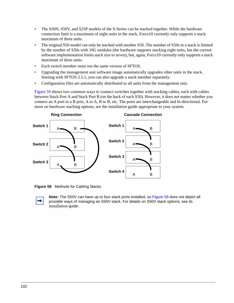
102
• The S50N, S50V, and S25P models of the S-Series can be stacked together. While the hardware connection limit is a maximum of eight units in the stack, Force10 currently only supports a stack maximum of three units.
• The original S50 model can only be stacked with another S50. The number of S50s in a stack is limited by the number of S50s with 10G modules (the hardware supports stacking eight units, but the current software implementation limits stack size to seven), but, again, Force10 currently only supports a stack maximum of three units.
• Each switch member must run the same version of SFTOS. • Upgrading the management unit software image automatically upgrades other units in the stack.
Starting with SFTOS 2.5.1, you can also upgrade a stack member separately.• Configuration files are automatically distributed to all units from the management unit.
Figure 59 shows two common ways to connect switches together with stacking cables, each with cables between Stack Port A and Stack Port B (on the back of each S50). However, it does not matter whether you connect an A port to a B port, A to A, B to B, etc. The ports are interchangeable and bi-directional. For more on hardware stacking options, see the installation guide appropriate to your system.
Figure 59 Methods for Cabling Stacks
Note: The S50V can have up to four stack ports installed, so Figure 59 does not depict all possible ways of managing an S50V stack. For details on S50V stack options, see its installation guide.
A BSwitch 1
A BSwitch 2
A BSwitch 3
Ring Connection Cascade Connection
A BSwitch 1
A BSwitch 2
A BSwitch 3
A BSwitch 4
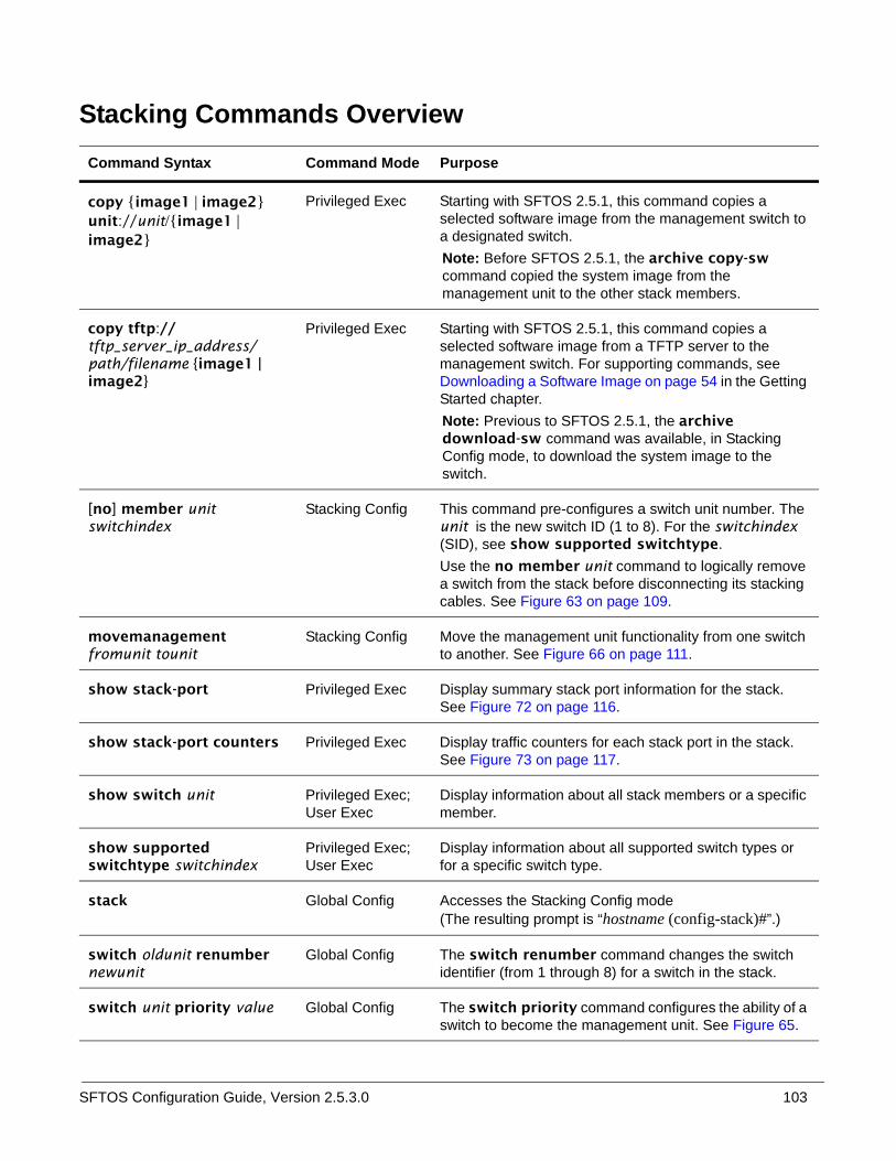
SFTOS Configuration Guide, Version 2.5.3.0 103
Stacking Commands Overview Command Syntax Command Mode Purpose
copy {image1 | image2} unit://unit/{image1 | image2}
Privileged Exec Starting with SFTOS 2.5.1, this command copies a selected software image from the management switch to a designated switch.Note: Before SFTOS 2.5.1, the archive copy-sw command copied the system image from the management unit to the other stack members.
copy tftp://tftp_server_ip_address/path/filename {image1 | image2}
Privileged Exec Starting with SFTOS 2.5.1, this command copies a selected software image from a TFTP server to the management switch. For supporting commands, see Downloading a Software Image on page 54 in the Getting Started chapter.Note: Previous to SFTOS 2.5.1, the archive download-sw command was available, in Stacking Config mode, to download the system image to the switch.
[no] member unit switchindex
Stacking Config This command pre-configures a switch unit number. The unit is the new switch ID (1 to 8). For the switchindex (SID), see show supported switchtype. Use the no member unit command to logically remove a switch from the stack before disconnecting its stacking cables. See Figure 63 on page 109.
movemanagement fromunit tounit
Stacking Config Move the management unit functionality from one switch to another. See Figure 66 on page 111.
show stack-port Privileged Exec Display summary stack port information for the stack. See Figure 72 on page 116.
show stack-port counters Privileged Exec Display traffic counters for each stack port in the stack. See Figure 73 on page 117.
show switch unit Privileged Exec; User Exec
Display information about all stack members or a specific member.
show supported switchtype switchindex
Privileged Exec; User Exec
Display information about all supported switch types or for a specific switch type.
stack Global Config Accesses the Stacking Config mode (The resulting prompt is “hostname (config-stack)#”.)
switch oldunit renumber newunit
Global Config The switch renumber command changes the switch identifier (from 1 through 8) for a switch in the stack.
switch unit priority value Global Config The switch priority command configures the ability of a switch to become the management unit. See Figure 65.

104
Management Unit Selection Algorithm• If a stack has an active management unit, and a switch being introduced to the stack is also configured
to be a management unit, then the newly added unit changes its configured value to disable the management unit function.
• Conversely, if the management unit function is enabled or unassigned on the unit and there is no other management unit in the system, then the unit becomes the management unit.
• If the management unit function is disabled on the unit, then it remains a non-management unit.• The priority preference (switch priority command) is only used to select the next management unit
when the current management unit fails.• When two units that constitute the members of a stack come up at the same time, then whichever has
the higher priority or higher MAC address becomes the management unit.• The current management unit has the highest default preference for staying the manager after a reboot.
On reboot, a member switch waits for 30 seconds to hear from the management unit before it begins to determine from its priority if it must become the management unit. Therefore, in addition to the movemanagement command cited above, you could force a change in management units in this way:
1. Power down the current management unit.
2. Reset the stack. Enter the reload command.
3. Wait more than 30 seconds before powering up the device again. At 30 seconds, the remaining units start the management unit election process.
Unit Number AssignmentYou can manually assign numbers to stack members. For details, see Adding a Switch to a Stack on page 107. Otherwise, SFTOS automatically assigns unit numbers based on the following factors.
• If the unit number is configured, but another unit already uses that number, the unit changes its configured unit number to the lowest unassigned unit number.
• If the unit number is unassigned, then the unit sets its configured unit number to the lowest unassigned unit number.
• If the unit number is configured and no other device uses the unit number, then the unit starts using the configured unit number.
• If a unit detects that the maximum number of units already exist, the unit sets its unit number to “unassigned” and stays in the Initialization state.
Stack Management and FunctionalityAs described above (Management Unit Selection Algorithm on page 104), a management selection algorithm elects one stack member to be the management unit. All other switches in the stack will be subordinate to the management unit and “assume its personality”. Each switch in the stack will have a unit number that you can configure, or they are set automatically by the individual units as they start (Unit

SFTOS Configuration Guide, Version 2.5.3.0 105
Number Assignment on page 104). Use the show switch command (Figure 61 on page 106) to see the status of the individual members in a stack.
It is possible to pre-configure the stack for new units. Use the member command (see Stacking Commands Overview on page 103) to accomplish this function. This will logically create the new unit and all the ports connected to that unit. You can define the new unit in advance, and pre-configure the ports even though the ports do not yet physically exist in the stack. If you do so, make sure you pre-assign the unit number to the new unit so that it will get the proper configuration from the management unit when connected to the stack. See the list of best practices (Best Practices on page 107). Pre-configured ports (not physically present) display in the show switch command report as “detached”.
Bear in mind that, if you connect a switch that already has a stack number that does not match the pre-configuration you did (perhaps it was previously a member of another stack), the switch will be assigned a default configuration by the management unit. If this occurs, use the switch renumber command to assign a stack number that matches the unit number you pre-configured for.
You can also use the the switch renumber command if you want to remove a unit that is the current backup to the management unit, and you want this new unit to assume the identity of that removed unit.
The management unit is in charge of the stack. If a new software image is loaded into the management unit, the image will be automatically propagated to all units (in fact it is required that all units run the same version of code). If configuration changes are made and saved, they will be saved to all switches, and remembered by all switches, even if the switches are disconnected from the stack. The management IP address is also included in that configuration information, so you could end up with duplicate addresses on the network if you simply remove the stacking cables from units that are connected to the same network.
If the management unit were to be removed, or it became non-functional for some reason, one of the other switches in the stack would then be elected manager by the management selection algorithm. It is possible to enforce which switch will become the replacement management unit, by configuring it to have the highest switch priority. Changing this priority in an operating stack will not affect the current stack configuration. The priority is only used by the algorithm when a new manager needs to be elected, such as after a power failure, or removal/failure of the current management unit.
You manage the stack from the management unit. When you connect to the console port of the management unit, you will see the expected prompt, and you have mode-based access to all CLI commands (For more on modes, see the CLI Modes chapter in the SFTOS Command Reference.)
If you connect to the console port on a non-management unit in a stack, the prompt is “(Unit number)>”. The number is the one assigned to that switch. No user commands can be executed at that prompt.
Note: Unit numbers are stored in NVRAM and are persistent, even when a unit is removed from a stack. The exceptions are if: 1) you change the unit number manually; or 2) you plug the unit into a new stack, and it gets assigned a new unit number because a unit in that new stack already has the same number.
Note: On a subordinate unit, the only command that shows up when you type '?' is devshell. This is used to access a low level diagnostic shell that should only be used under the direction of a TAC engineer. Unauthorized use of this shell could disrupt the functioning of your unit.

106
All of the forwarding protocols run on the management unit. The subordinate units do not run the full stack. The forwarding database resides on the management unit, which then synchronizes the forwarding tables in the other units in the stack. The individual units in the stack then make individual forwarding decisions based on their local copy of the forwarding table.
If a management unit is lost, and a new unit assumes the role of manager for the stack, there is some disruption to traffic as the new management unit is elected, and forwarding tables are flushed and then relearned.
The stacking ports switch traffic between units at a rate of 10 Gbps. Since each unit supports 48 x 1 Gbps ports, and two optional 10 Gbps ports, the switching capacity between units is oversubscribed.
The ring topology provides some performance gains. For example, a two-unit stack with two cables is able to exploit the full bandwidth of both stacking ports, effectively giving 20 Gbps between the units. Ring topology performance gains in larger stacks (4+) will probably not be as great, since transitional traffic will share bandwidth with traffic destined to, or originating from, a given switch.
To display the status of the stacking ports, execute the show stack or show stack-port command (In this example, the redundant connection that completes a ring topology is missing.):
Figure 60 Example Output from show stack-port Command on an S50
To display the status of units in the stack and which version of software they are running, use the show switch command:
Figure 61 Example Output from show switch Command
Force10 #show stack-portConfigured Running
Stack Stack Link LinkUnit Interface Mode Mode Status Speed (Gb/s)---- ---------------- ---------- ---------- ------------ ------------1 Stack Port A N/A Stack Link Down 10 1 Stack Port B N/A Stack Link Up 10 2 Stack Port A N/A Stack Link Up 10 2 Stack Port B N/A Stack Link Down 10
Force10 #show switch
Management Preconfig Plugged-in Switch Code Switch Status Model ID Model ID Status Version------ ------------ ------------- ------------- --------------------- --------1 Mgmt Switch SA-01-GE-48T SA-01-GE-48T OK 2.3.1.5 2 Stack Member SA-01-GE-48T SA-01-GE-48T OK 2.3.1.5
ManagerMember

SFTOS Configuration Guide, Version 2.5.3.0 107
Adding a Switch to a Stack
SFTOS provides three ways to add a switch to a stack:
• Plug the unit into the stack and let the system configure it. The unit is automatically assigned the next unused unit number.
• Power the unit up as a standalone unit to assign a unit number and management unit preference before connecting the unit to the stack. Use the member command (Figure 62 on page 108) and switch priority command (Figure 65 on page 110).
• Pre-configure the unit number (member command) through the stack’s management unit and then connect the unit to the stack. If you are adding multiple units to an existing stack, you can either:— Configure the unit numbers from the pre-configuration into the standalone units before connecting
them.Or
— Plug the units into the stack in the correct sequence to match the pre-configuration. After a running configuration has been saved, all units are considered to be pre-configured.
Best PracticesAs best practices, to minimize disruption to the stack (and network) when connecting units and during failures, you should:
1. Pre-configure unit numbers for each unit in the stack. Use the switch renumber command.
2. Configure the switch priority for each unit to make management unit selection deterministic. Use the switch priority command.
3. Make sure each unit has the same software version prior to connecting them together. If you do connect them, the CLI will issue an error and not allow the stacking connection.
4. Make sure you save the configuration after making changes. The configuration will be saved to all units in the stack. If you do not save changes, and a management unit were to fail, the changes would be lost. Other units in the stack would not learn about the changes, or store them, unless they are saved.
5. Connect new units to an existing stack prior to powering them up. Failure to do so will not result in physical damage, but a new unit that was previously configured as a management unit, that gets connected to an existing stack, could end up as the manager, disrupting expected stack operation.
Note: Force10 currently supports a stack maximum of three units. S50 models can only stack with other S50 models. The S25P, S50N, and S50V can be stacked together. See the Quick Reference appropriate to your S-Series model or its installation guide for instructions on making the physical stacking connections.

108
Use the member unit switchindex command to logically add a unit to a stack as a way to pre-configure it before physically adding it. In this case, we add the unit as #5:
Figure 62 Using the member Command to Add a Unit to a Stack
Removing a Switch from a StackUse the following procedure to remove a member switch from a stack (If you are removing the management unit, first use the movemanagement command, as described above):
Step Command Syntax Command Mode Purpose
1 interface range ethernet range
Global Config Access the range of interfaces on the switch to be removed from the stack. The command accesses the Ethernet Range prompt within the Interface Range mode. For example, for Unit 2, enter:interface range ethernet 2/0/1-2/0/50
2 shutdown Interface Range Disable all ports in the specified range.Alternatively, you could pull all of the port connections from the switch.
3 Remove the stacking cables from the unit to be removed from the stack.
4 stack Global Config Access Stacking Config mode.
Force10 #show supported switchtype
Mgmt CodeSID Switch Model ID Pref Type--- -------------------------------- ------------ ---------1 SA-01-GE-48T 1 0x100b0003 SA-01-GE-48T 1 0x100b0004 SA-01-GE-48T 1 0x100b000
Force10 #configure Force10 (Config)#stack Force10 (config-stack)#member 5 1Force10 (config-stack)#exitForce10 (Config)#exitForce10 #show switch
Management Preconfig Plugged-in Switch Code Switch Status Model ID Model ID Status Version------ ------------ ------------- ------------- --------------------- --------1 Mgmt Switch SA-01-GE-48T SA-01-GE-48T OK 2.3.1.5 3 Stack Member SA-01-GE-48T SA-01-GE-48T OK 2.3.1.5 4 Stack Member SA-01-GE-48T SA-01-GE-48T OK 2.3.1.5 5 Unassigned SA-01-GE-48T Not Present 0.0.0
Force10 #
Unit 5 added
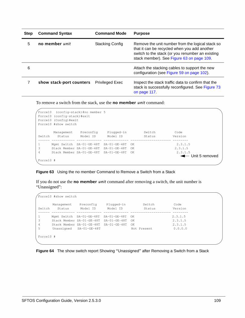
SFTOS Configuration Guide, Version 2.5.3.0 109
To remove a switch from the stack, use the no member unit command:
Figure 63 Using the no member Command to Remove a Switch from a Stack
If you do not use the no member unit command after removing a switch, the unit number is “Unassigned”:
Figure 64 The show switch report Showing “Unassigned” after Removing a Switch from a Stack
5 no member unit Stacking Config Remove the unit number from the logical stack so that it can be recycled when you add another switch to the stack (or you renumber an existing stack member). See Figure 63 on page 109.
6 Attach the stacking cables to support the new configuration (see Figure 59 on page 102).
7 show stack-port counters Privileged Exec Inspect the stack traffic data to confirm that the stack is successfully reconfigured. See Figure 73 on page 117.
Step Command Syntax Command Mode Purpose
Force10 (config-stack)#no member 5Force10 (config-stack)#exitForce10 (Config)#exitForce10 #show switch
Management Preconfig Plugged-in Switch Code Switch Status Model ID Model ID Status Version------ ------------ ------------- ------------- --------------------- --------1 Mgmt Switch SA-01-GE-48T SA-01-GE-48T OK F32.3.1.5 3 Stack Member SA-01-GE-48T SA-01-GE-48T OK F2.3.1.5 4 Stack Member SA-01-GE-48T SA-01-GE-48T OK F32.3.1.5
Force10 #Unit 5 removed
Force10 #show switch
Management Preconfig Plugged-in Switch CodeSwitch Status Model ID Model ID Status Version------ ------------ ------------- ------------- --------------------- --------1 Mgmt Switch SA-01-GE-48T SA-01-GE-48T OK 2.3.1.53 Stack Member SA-01-GE-48T SA-01-GE-48T OK 2.3.1.5 4 Stack Member SA-01-GE-48T SA-01-GE-48T OK 2.3.1.5 5 Unassigned SA-01-GE-48T Not Present 0.0.0.0
Force10 #

110
Setting Management Unit PreferencesTo change the management unit priority of a stack member, use the switch unit priority value command:
Figure 65 Changing Switch Unit Priority
In the example in Figure 65, the switch 4 priority 2 command changes the management preference value of Unit #4 to priority 2. The higher the number, the more likely it is that the switch will be selected as the next management unit by the management selection algorithm. The default is 1, so unless other units have been set with a higher priority, Unit #4 will be selected to be the management unit when the current management unit goes down or is removed from the stack.
Force10 (Config)#switch 4 priority 2Force10 (Config)#exitForce10 #show switch
Management Preconfig Plugged-in Switch Code Switch Status Model ID Model ID Status Version------ ------------ ------------- ------------- --------------------- --------1 Stack Member SA-01-GE-48T SA-01-GE-48T OK 2.3.1.5 3 Mgmt Switch SA-01-GE-48T SA-01-GE-48T OK 2.3.1.5 4 Stack Member SA-01-GE-48T SA-01-GE-48T OK 2.3.1.5
Force10 #show switch 4
Switch............................ 4Management Status................. Stack MemberHardware Management Preference.... UnassignedAdmin Management Preference....... 2Switch Type....................... 0x56950202Preconfigured Model Identifier.... SA-01-GE-48TPlugged-in Model Identifier....... SA-01-GE-48TSwitch Status..................... OKSwitch Description................ Expected Code Type................ 0x100b000Detected Code Version............. 2.3.1.5Detected Code in Flash............ 2.3.1.5Serial Number..................... DE400347Up Time........................... 0 days 0 hrs 56 mins 51 secs
Value is now set to priority 2

SFTOS Configuration Guide, Version 2.5.3.0 111
To move the management function from one unit to another within a stack, use the movemanagement command:
Figure 66 Moving the Management Unit Function within a Stack
Inspecting Management PreferencesThe command show switch number (see an example in Figure 61 on page 106; see also Verifying Details about the Switch on page 41) generates a report that displays a field called “Hardware Management Preference” and one called “Admin Management Preferences”, as described here.
(Unit 3)>(Unit 3)>This switch is manager of the stack.STACK: attach 5 units on 1 cpu
User:Trying to attach more units.....This switch is manager of the stack.STACK: attach 5 units on 1 cpuTrying to attach more units.....This switch is manager of the stack.STACK: attach 5 units on 1 cpu
User:
User:*****Password:Force10 >enablePassword:
Force10 #show switch
Management Preconfig Plugged-in Switch CodeSwitch Status Model ID Model ID Status Version------ ------------ ------------- ------------- --------------------- --------1 Stack Member SA-01-GE-48T SA-01-GE-48T OK 2.3.1.53 Mgmt Switch SA-01-GE-48T SA-01-GE-48T OK 2.3.1.54 Stack Member SA-01-GE-48T SA-01-GE-48T OK 2.3.1.5
Force10 #
Management Switch is now Unit 3
Force10 (config-stack)#movemanagement 1 3Moving stack management will unconfigure entire stack including all interfaces.Are you sure you want to move stack management? (y/n) y
Force10 (config-stack)#(Unit 1)>This switch is not manager of the stack.STACK: detach 15 units
(Unit 1)>Unit 1 no longer has CLI
Log into Unit 3

112
Hardware Management Preference
The “Hardware Management Preference” field indicates whether the device is capable of becoming a management unit. The value for Hardware Management Preference always displays as “Unassigned.” The other valid value for this field is “Disabled”. The attribute cannot be changed through the CLI.
Administrative Management Preference
The “Administrative Management Preference” indicates the preference given to this unit over another units in a stack by an administrator when the management unit fails. The default value is 1. A value of 0 means the unit cannot become a management unit.
This field indicates the administrative management preference value assigned to the switch. This preference value indicates how likely the switch is to be chosen as the management unit. The attribute for “Admin Management Preferences” can be changed through the switch unit_number priority value command.
Unsetting Management Preference
There is no CLI command to set the management preference back to “unassigned”. The management preference information is stored locally on each unit, and can be erased using the boot menu option that deletes all configuration files including the unit number.
Management Preference and MAC Address
The role of each switch in a stack as either manager or member can be changed by setting the management preference and MAC address. Management preference is considered before the MAC address. The higher the management preference value is makes it more likely for that switch to become manager. Likewise, the higher the MAC address value is makes it more likely for that switch to become manager.
The preference decision is made only when the current manager fails and a new manager needs to be selected, or when a stack of units is powered up with none of the units previously holding the management role. If two managers are connected together, then management preference has no effect.
Upgrading Software in a StackWith all versions of SFTOS, using the copy command to download SFTOS software to the management switch automatically propagates that software to all stack members. You would then use the reload command to reboot all switches in the stack, which would include installing that new software.
However, in SFTOS 2.5.1, the copy command syntax is slightly different. When you use the copy command to download software while running 2.5.1, you specify in which of two bins (image1 or image2), the new software will be stored:
copy tftp://tftp_server_ip_address/path/filename {image1 | image2}

SFTOS Configuration Guide, Version 2.5.3.0 113
Previous to SFTOS 2.5.1, the syntax is:
copy tftp://tftp_server_ip_address/path/filename system:image
(If you are using XModem, instead, replace tftp with xmodem.)
For more on downloading SFTOS, see Downloading a Software Image on page 54 in the Getting Started chapter. See also the command syntax for the set of Dual Software Image Management commands in that section of the System Configuration Commands chapter in the SFTOS Command Reference.
The purpose of the two “image” bins is to enable you to easily specify which image to invoke on the next reboot. You do that with the command boot system [unit] {image1 | image2} before executing the reload command.
Note that it is possible to download new software into the bin currently occupied by the currently running version. The replacement would only take effect on the next reboot and only if you specified that bin with the boot system command.
The reload [unit] command now provides selective rebooting of stack members. Combined with the ability in SFTOS 2.5.1 to select which software image is invoked in a reboot, you have various options in choosing which software is launched in specific stack members. For example, you might choose to reboot a particular member without installing the new code copied to it.
Copying SFTOS Software to a Member Switch
As described above, downloading SFTOS software to the management switch automatically propagates that software to all stack members. In addition, with SFTOS 2.5.1, the copy command provides the following way to manually copy an image from the management switch to a selected stack member, typically one that does not yet have the software version set to be installed in the next reboot:
copy {image1 | image2} unit://unit/{image1 | image2}For unit, enter a specific member number as an integer from 1 to 6.
An asterisk (* ) indicates that the image should be copied to all members:unit://*/{image1 | image2}
For more on copy command options, see Downloading and Uploading Files on page 52, above.
Configuration example: Upgrading software on a new member switch
In the following case, a switch has been moved into a stack after you have installed new software to the management unit and to the new member. You have installed the new software in the management unit but not yet in the new member.
T
Note: This operation can take several minutes.
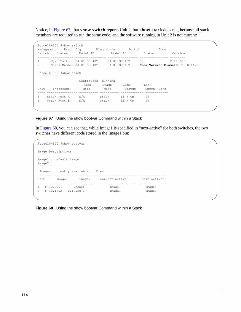
114
Notice, in Figure 67, that show switch reports Unit 2, but show stack does not, because all stack members are required to run the same code, and the software running in Unit 2 is not current:
Figure 67 Using the show bootvar Command within a Stack
In Figure 68, you can see that, while Image1 is specified in “next-active” for both switches, the two switches have different code stored in the Image1 bin:
Figure 68 Using the show bootvar Command within a Stack
Force10-S50 #show switchManagement Preconfig Plugged-in Switch CodeSwitch Status Model ID Model ID Status Version------ ------------ ---------------- ---------------- --------------- --------1 Mgmt Switch SA-01-GE-48T SA-01-GE-48T OK F.10.20.12 Stack Member SA-01-GE-48T SA-01-GE-48T Code Version Mismatch F.10.16.2
Force10-S50 #show stack
Configured RunningStack Stack Link Link
Unit Interface Mode Mode Status Speed (Gb/s)---- ---------------- ---------- ---------- ------------ ------------1 Stack Port A N/A Stack Link Up 101 Stack Port B N/A Stack Link Up 10
Force10-S50 #show bootvar
Image Descriptions
image1 : default imageimage2 :
Images currently available on Flash--------------------------------------------------------------------unit image1 image2 current-active next-active--------------------------------------------------------------------1 F.10.20.1 <none> image1 image12 F.10.16.2 F.10.20.1 image1 image1

SFTOS Configuration Guide, Version 2.5.3.0 115
1. Use the boot system command to set Image2 as the code to install on the next reboot of Unit 2, and then inspect the show bootvar output again to verify the selection of Image2 in “next-active”:
Figure 69 Using the show bootvar Command within a Stack
2. After executing the reload 2 command to reboot Unit 2, use the show switch command to verify that the stack is running the new code:
Figure 70 Verifying Stack Sequencing after a Reload with show switch and show stack Commands
Force10-S50 #boot system 2 image2Activating image image2 ..
Force10-S50 #show bootvar
Image Descriptions
image1 : default imageimage2 :
Images currently available on Flash--------------------------------------------------------------------unit image1 image2 current-active next-active--------------------------------------------------------------------1 F.10.20.1 <none> image1 image12 F.10.16.2 F.10.20.1 image1 image2
Force10-S50 #reload 2
Are you sure you want to reload the switch? (y/n) y
Reloading switch 2.................Force10-S50 #STACK: master on 0:1:e8:d5:c2:21 (2 cpus, 12 units)Trying to attach more units.....STACK: master on 0:1:e8:d5:c2:21 (2 cpus, 12 units)STACK: attach 7 units on 1 cpuThis switch is manager of the stack.
Force10-S50 >show switch
Management Preconfig Plugged-in Switch CodeSwitch Status Model ID Model ID Status Version------ ------------ ---------------- ---------------- --------------- --------1 Mgmt Switch SA-01-GE-48T SA-01-GE-48T OK F.10.20.12 Stack Member SA-01-GE-48T SA-01-GE-48T OK F.10.20.1
Force10-S50 #show stack
Configured RunningStack Stack Link LinkUnit Interface Mode Mode Status Speed (Gb/s)---- ---------------- ---------- ---------- ------------ ------------1 Stack Port A N/A Stack Link Up 101 Stack Port B N/A Stack Link Up 102 Stack Port A N/A Stack Link Up 102 Stack Port B N/A Stack Link Up 10

116
Using show Commands for Stacking InformationUse show commands to gather information about stack members. In this chapter, see the following examples of using show commands:
• show stack-port: See Figure 60 on page 106.• show switch: See Figure 61 on page 106, Figure 62 on page 108, Figure 63 on page 109, and
Figure 64 on page 109.• show supported switchtype: See Figure 62 on page 108.• show bootvar: See Figure 67 on page 114, Figure 68 on page 114, and Figure 69 on page 115.• show stack: See Figure 70 on page 115 and Figure 75 on page 118.
To show information about MAC addresses in a stack, use the show mac-addr-table command:
Figure 71 Using the show mac-addr-table Command Example
To show information about stack port status, use the show stack-port command:
Figure 72 Using the show stack-port Command Example
Note: The “0/3/1” in the Interface column references the CPU.
Force10 #show mac-addr-tableMac Address Interface IfIndex Status ----------------------- --------- ------- ------------00:01:00:01:00:00:00:01 2/0/37 87 Learned 00:01:00:01:00:00:00:37 1/0/1 1 Learned 00:01:00:03:00:00:00:03 1/0/2 2 Learned 00:01:00:03:00:00:00:39 2/0/38 88 Learned 00:01:00:04:00:00:00:45 2/0/45 95 Learned 00:01:00:04:00:00:00:46 1/0/45 45 Learned 00:01:00:06:00:00:00:47 2/0/46 96 Learned 00:01:00:06:00:00:00:48 1/0/46 46 Learned 00:01:00:D0:95:B7:CD:2E 0/3/1 401 Management
Force10 #show stack-portConfigured Running
Stack Stack Link LinkUnit Interface Mode Mode Status Speed (Gb/s)---- ---------------- ---------- ---------- ------------ ------------1 Stack Port A N/A Stack Link Down 101 Stack Port B N/A Stack Link Up 102 Stack Port A N/A Stack Link Up 102 Stack Port B N/A Stack Link Down 10

SFTOS Configuration Guide, Version 2.5.3.0 117
To show activity at the stack ports, use the show stack-port counters command:
Figure 73 Using the show stack-port counters Command Example on an S50
For a summary of all stack members, use the show switch command. For details on one switch, use the show switch unit command:
Figure 74 show switch Command Example
Force10 #show stack-port counters ------------TX-------------- ------------RX-------------- Data Error Data Error Rate Rate Total Rate Rate TotalUnit Interface (Mb/s) (Errors/s) Errors (Mb/s) (Errors/s) Errors---- ---------------- ------ ---------- ---------- ------ ---------- ----------1 Stack Port A 0 0 0 0 0 01 Stack Port B 0 0 0 0 0 02 Stack Port A 0 0 0 0 0 02 Stack Port B 0 0 0 0 0 0
Force10 #show switch
Management Preconfig Plugged-in Switch Code Switch Status Model ID Model ID Status Version------ ------------ ------------- ------------- --------------------- --------1 Mgmt Switch SA-01-GE-48T SA-01-GE-48T OK 2.3.1.5 3 Stack Member SA-01-GE-48T SA-01-GE-48T OK 2.3.1.5 4 Stack Member SA-01-GE-48T SA-01-GE-48T OK 2.3.1.5
Force10 #show switch 1
Switch............................ 1Management Status................. Management SwitchHardware Management Preference.... UnassignedAdmin Management Preference....... UnassignedSwitch Type....................... 0x56950202Preconfigured Model Identifier.... SA-01-GE-48TPlugged-in Model Identifier....... SA-01-GE-48TSwitch Status..................... OKSwitch Description................ Expected Code Type................ 0x100b000Detected Code Version............. 2.3.1.5Detected Code in Flash............ 2.3.1.5Serial Number..................... DE40047Up Time........................... 0 days 0 hrs 33 mins 55 secs
ManagerMemberMember

118
The show stack command shows pretty much the same data as the show stack-port command:
Figure 75 show stack Command Example
Force10 #show stack
Configured Running Stack Stack Link LinkUnit Interface Mode Mode Status Speed (Gb/s)---- ---------------- ---------- ---------- ------------ ------------1 Stack Port A N/A Stack Link Up 10 1 Stack Port B N/A Stack Link Up 10 2 Stack Port A N/A Stack Link Up 10 2 Stack Port B N/A Stack Link Up 10 3 Stack Port A N/A Stack Link Up 10 3 Stack Port B N/A Stack Link Up 10

SFTOS Configuration Guide, Version 2.5.3.0 119
This chapter contains overview information on interfaces supported by SFTOS, along with information on configuring physical interfaces, in the following sections:
• Interface Support in SFTOS• Viewing Interface Information on page 120• Viewing Layer 3 Interface Information on page 125• Configuring Physical Interfaces on page 125• Bulk Configuration on page 134
Interface Support in SFTOSSFTOS supports the following interface types (SFTOS does not support null interfaces.):
• 10/100/1000 Ethernet ports• Gigabit Ethernet ports (1G)• 10 Gigabit Ethernet ports (10G)• Loopback (logical interface): For loopback interface syntax, see the System Configuration chapter
in the SFTOS Command Reference. For information on the loopback ACL, see Protecting the Management Interface with a Loopback ACL on page 210.
• Layer 2 and Layer 3 VLANs: See VLANs on page 215 and VLAN Routing on page 270.• Layer 2 and Layer 3 port channels (LAGs): See Link Aggregation on page 173.• Console port (TTY emulation): See Connecting to the Console Port on page 37.• IP-based Management Ethernet: See Creating the Management IP Address on page 75.
In the S-Series, you can place physical interfaces, port channel interfaces, and VLANs in either Layer 2 or Layer 3 mode (Table 3).
Chapter 6 Configuring Interfaces
Table 3 Interfaces in the S-Series
Type of InterfaceModes Possible
Require Creation Default State
10/100/1000 Ethernet, 1G, 10G Layer 2Layer 3
NoYes
Shut down (disabled)
Management Ethernet n/a No Shut down (disabled)

120
*The Default VLAN (VLAN 1) does not require creation, but it can be modified.
Physical and logical interfaces are automatically in Layer 2 mode. To place an interface in Layer 3 mode, assign an IP address to that interface (see Configuring Layer 3 Mode on page 130). These interfaces also contain Layer 2 and Layer 3 commands to configure and modify the interfaces.
Viewing Interface InformationS-Series (SFTOS) ports are configured for Layer 2 by default, so you do not need to explicitly configure them as Layer 2, as you do on the E-Series (FTOS). Initially, the running configuration file simply displays the series of ports without any configuration annotations. As you configure a port, those changes appear in the running configuration following the affected port.
For example, Figure 76 shows part of a running configuration; it displays the configuration for the series of ports numbered 1/0/45 through 1/0/48. Each port listing is followed by no shutdown to indicate that each of these ports has been enabled.
Figure 76 show running-config Command Example Showing Layer 2 Interface Information
Port Channel Layer 2Layer 3
YesYes
Shut down (disabled)
VLAN Layer 2 Layer 3
Yes*Yes
Enabled (active for Layer 2)Shut down (disabled for Layer 3)
Table 3 Interfaces in the S-Series
Type of InterfaceModes Possible
Require Creation Default State
Force10 #show running-config!--initial output deleted--!
interface 1/0/45no shutdownexit
interface 1/0/46no shutdownexit
interface 1/0/47no shutdownexit
interface 1/0/48no shutdownexit
!--Output truncated--!

SFTOS Configuration Guide, Version 2.5.3.0 121
In addition to inspecting the running config, as described above (see Figure 76), the CLI provides multiple commands to inspect the status and configuration of interfaces:
• show interface managementethernet: Use this command, in either Privileged Exec mode or User Exec mode (the only command in this set that is available in User Exec mode), to display the current Management Ethernet interface settings. See Verifying Access to a Management Port on page 77.
• show interface switchport: Displays a packet transmission summary for the switch. See Figure 77.• show interface unit/slot/port: Enter the port number of a particular port to query, where unit is the
stack member, slot is always 0 (zero), and port is the port number. This command provides a summary of packets received and transmitted on the designated interface. For sample S50 and S50V output, see Figure 78 and Figure 79 on page 122, respectively.
• show interface ethernet switchport: Displays more packet transmission details for the switch than the show interface switchport command. See Figure 80 on page 123.
• show interfaces cos-queue [unit/slot/port]: The unit/slot/port parameter (as described above) is optional. If specified, the class-of-service queue configuration of the interface is displayed. If omitted, the most recent global configuration settings are displayed. See Figure 81 on page 123.
• show interface ethernet unit/slot/port: Displays details on port activity on the designated interface. See Figure 82 on page 124.
• show interfaces description {unit/slot/port | 1-3965}: Enter an interface ID, in unit/slot/port format, to report on a particular interface, or enter a VLAN ID to display information for that VLAN.
• show port description unit/slot/port: Enter an interface ID, in unit/slot/port format, to display the user-entered description of the selected interface. You enter the description in this way, from Global Config mode:
interface unit/slot/port
description line
Figure 77 Using the show interface switchport Command for Switch Summary Packet Information
a
Note: The port LEDs on the face of the switch also provide status information. For details, see the hardware guide for your switch.
Force10 #show interface switchport
Broadcast Packets Received..................... 0Packets Received With Error.................... 0Packets Transmitted Without Errors............. 0Broadcast Packets Transmitted.................. 0Transmit Packet Errors......................... 0Address Entries Currently in Use............... 1VLAN Entries Currently in Use.................. 1Time Since Counters Last Cleared............... 0 day 0 hr 25 min 47 sec
Force10 #

122
Figure 78 S50 Model: The show interface Command for Summary Packet Information for One Port
Contrast the output in Figure 78, for the S50 model, to that of Figure 79, for the S50V
Figure 79 S50V Model: The show interface Command for Summary Packet Information for One Port
Force10 #show interface 1/0/1 Ports 1 through 48Packets Received Without Error................. 0 Packets Received With Error.................... 0Broadcast Packets Received..................... 0Packets Transmitted Without Errors............. 0Transmit Packet Errors......................... 0Collision Frames............................... 0Time Since Counters Last Cleared............... 0 day 0 hr 25 min 38 sec
Force10 #
Force10-S50V#show interface 1/0/1
Packets Received Without Error................. 1555Packets Received With Error.................... 0Broadcast Packets Received..................... 642Packets Transmitted Without Errors............. 0Transmit Packet Errors......................... 0Collision Frames............................... 0Time Since Counters Last Cleared............... 3 day 20 hr 59 min 6 secNative Vlan.................................... 1
Rate Info (interval 300 seconds):Packets Rx Rate Mbits/sec...................... 00.00Packets Tx Rate Mbits/sec...................... 00.00Packets Rx Rate packets/sec.................... 00.00Packets Tx Rate packets/sec.................... 00.00Packets Rx Line Rate........................... 0.00%Packets Tx Line Rate........................... 0.00%
Force10-S50V#

SFTOS Configuration Guide, Version 2.5.3.0 123
Figure 80 The show interface ethernet switchport Command for Detailed Packet Data on the Switch
The show interfaces cos-queue [unit/slot/port], with and without the unit/slot/port parameter, produces almost the same report — one version for the interface and the other for the switch. The version of the report generated with the unit/slot/port parameter is shown in Figure 81.
Figure 81 Using the show interfaces cos-queue Command for Port QoS Details
Force10 #show interface ethernet switchport
Total Packets Received (Octets)................ 0Unicast Packets Received....................... 0Multicast Packets Received..................... 0Broadcast Packets Received..................... 0Receive Packets Discarded...................... 0
Octets Transmitted............................. 0Packets Transmitted Without Errors............. 0Unicast Packets Transmitted.................... 0Multicast Packets Transmitted.................. 0Broadcast Packets Transmitted.................. 0Transmit Packets Discarded..................... 0Most Address Entries Ever Used................. 1Address Entries Currently in Use............... 1
Maximum VLAN Entries........................... 1024Most VLAN Entries Ever Used.................... 1Static VLAN Entries............................ 1Dynamic VLAN Entries........................... 0VLAN Deletes................................... 0Time Since Counters Last Cleared............... 0 day 0 hr 25 min 45 sec
Force10 #
Force10 #show interfaces cos-queue 1/0/1
Interface...................................... 1/0/1Interface Shaping Rate......................... 0
Queue Id Min. Bandwidth Scheduler Type Queue Management Type -------- -------------- -------------- --------------------- 0 0 Weighted Tail Drop 1 0 Weighted Tail Drop 2 0 Weighted Tail Drop 3 0 Weighted Tail Drop 4 0 Weighted Tail Drop 5 0 Weighted Tail Drop 6 0 Weighted Tail Drop
Force10 #

124
Use the show interface ethernet unit/slot/port command for detailed packet information for the designated port, as shown in Figure 82 on page 124.
Figure 82 Checking Detailed Interface Counters Per Port Using show interface ethernet
The “Packets RX and TX 1519-1522 Octets” frame counter in the show interface ethernet report (Figure 82) is incremented only for VLAN-tagged frames. Untagged frames with that size increment the “Packets Received > 1522 Octets” counter.
Force10 #show interface ethernet 1/0/43
Total Packets Received (Octets)................ 16217658Packets Received > 1522 Octets................. 0Packets RX and TX 64 Octets.................... 3260Packets RX and TX 65-127 Octets................ 11968Packets RX and TX 128-255 Octets............... 6329Packets RX and TX 256-511 Octets............... 4812Packets RX and TX 512-1023 Octets.............. 338Packets RX and TX 1024-1518 Octets............. 7710Packets RX and TX 1519-1522 Octets............. 0Packets RX and TX 1523-2047 Octets............. 0Packets RX and TX 2048-4095 Octets............. 0Packets RX and TX 4096-9216 Octets............. 0
Total Packets Received Without Errors.......... 34091Unicast Packets Received....................... 30641Multicast Packets Received..................... 2010Broadcast Packets Received..................... 1440Total Packets Received with MAC Errors......... 0Jabbers Received............................... 0Fragments/Undersize Received................... 0Alignment Errors............................... 0FCS Errors..................................... 0Overruns....................................... 0
Total Received Packets Not Forwarded........... 0Local Traffic Frames........................... 0802.3x Pause Frames Received................... 0Unacceptable Frame Type........................ 0Multicast Tree Viable Discards................. 0Reserved Address Discards...................... 0Broadcast Storm Recovery....................... 0CFI Discards................................... 0Upstream Threshold............................. 0
Total Packets Transmitted (Octets)............. 52084Max Frame Size................................. 1518
Total Packets Transmitted Successfully......... 326Unicast Packets Transmitted.................... 105Multicast Packets Transmitted.................. 0Broadcast Packets Transmitted.................. 221Total Transmit Errors.......................... 0FCS Errors..................................... 0Tx Oversized................................... 0Underrun Errors................................ 0
Total Transmit Packets Discarded............... 0Single Collision Frames........................ 0Multiple Collision Frames...................... 0Excessive Collision Frames..................... 0Port Membership Discards....................... 0
802.3x Pause Frames Transmitted................ 0GVRP PDUs received............................. 0GVRP PDUs Transmitted.......................... 0GVRP Failed Registrations...................... 0GMRP PDUs Received............................. 0GMRP PDUs Transmitted.......................... 0GMRP Failed Registrations...................... 0
STP BPDUs Transmitted.......................... 0STP BPDUs Received............................. 0RSTP BPDUs Transmitted......................... 0RSTP BPDUs Received............................ 0MSTP BPDUs Transmitted......................... 0MSTP BPDUs Received............................ 0EAPOL Frames Transmitted....................... 0EAPOL Start Frames Received.................... 0
Time Since Counters Last Cleared............... 0 day 5 hr 7 min 16 sec

SFTOS Configuration Guide, Version 2.5.3.0 125
Viewing Layer 3 Interface Information
To enable Layer 3 traffic on a particular interface, use the ip routing command in Global Config mode to enable routing for the system, then add an IP address to the selected interface using the ip address command — in Interface Config mode for a port or port channel, and in Interface VLAN mode for a VLAN. For details, see Layer 3 Routing on page 255.
In all interface types except VLANs, the shutdown command stops all traffic from passing through the interface. Layer 2 VLANs can only be disabled by disabling each port in the VLAN. A Layer 3 VLAN can be disabled by removing its IP address. Layer 2 traffic on the VLAN is unaffected by this action.
Before you configure or enter a Layer 3 protocol mode (for example, OSPF), you must put at least one interface in Layer 3 mode, but not necessarily enabled. To inspect the system for Layer 3 interfaces, use the show ip interface brief command, which returns the report format shown in Figure 83.
Figure 83 show ip interface brief Command Example of a Layer 3 Interface
Configuring Physical InterfacesThe following basic configuration tasks for physical interfaces are discussed in this chapter:
• Enabling an Interface on page 128 (mandatory)• Configuring Speed and Duplex Mode on page 128 (optional)• Clearing Interface Counters on page 130 (optional)• Enabling Power over Ethernet Ports (PoE) on page 131 (optional)
As described in Interface Support in SFTOS on page 119, three Layer 2 port types are available in S-Series switches: 10/100/1000 Ethernet, Gigabit Ethernet (1G), and 10 Gigabit Ethernet (10G). The management Ethernet interface is another S-Series interface, which is enabled on some S-Series switch types as a dedicated port and on all S-Series switches as a type of configuration on the management VLAN. This interface type provides IP-based management access to the S-Series.
By default, all physical interfaces are disabled to traffic and set to auto-negotiate speed and duplex mode. On 10/100/1000 ports and 1G ports, you can manually set the speed and duplex mode. You cannot manually set the speed and duplex mode of 10G ports.
Note: Layer 3 interfaces can only be created with the Layer 3 Package of SFTOS. Use the show version command to determine what package is installed. See Figure 8 on page 43.
Force10 #show ip interface brief
Netdir MultiInterface IP Address IP Mask Bcast CastFwd--------- --------------- --------------- -------- --------1/0/3 10.0.0.2 255.255.255.0 Disable Disable

126
Physical interfaces can become part of virtual interfaces such as VLANs or Link Aggregation Groups (LAGs), also called port channels:
• For more information on VLANs, see VLANs on page 215. • For more information on port channels, see Link Aggregation on page 173.
The System Configuration chapter of the SFTOS Command Reference details the commands used in this chapter.
You can duplicate the execution of a particular configuration command against an interface without repercussion. For example, you can execute the no shutdown command twice on a port. The first use of the command enables the port. The second use of the command has no effect.
Nevertheless, as a best practice, you should determine the status of physical interfaces before executing commands on them. For that purpose, you can select from the commands described in Viewing Interface Information on page 120.
Another option is the show port all command, the use of which is shown below in Figure 84. When used against a stack of S50s, ports on all member units are displayed (The sample in Figure 84 is truncated at port 18.)
Figure 84 Interfaces Listed in the show port all Command (Partial)
The show port all command generates a report with the following fields:
• Intf—Valid unit, slot and port number separated by forward slashes.• Type—If not blank, this field indicates that this port is a special type of port. The possible values are:
Force10 #show port all
Admin Physical Physical Link Link LACP Intf Type Mode Mode Status Status Trap Mode ------ ------ ------- ---------- ---------- ------ ------- -------1/0/1 Enable Auto Down Enable Enable 1/0/2 Enable Auto 1000 Full Up Enable Enable 1/0/3 Disable Auto Down Enable Enable 1/0/4 Disable Auto Down Enable Enable 1/0/5 Disable Auto Down Enable Enable 1/0/6 Disable Auto Down Enable Enable 1/0/7 Disable Auto Down Enable Enable 1/0/8 Disable Auto Down Enable Enable 1/0/9 Disable Auto Down Enable Enable 1/0/10 Disable Auto Down Enable Enable 1/0/11 Disable Auto Down Enable Enable 1/0/12 Disable Auto Down Enable Enable 1/0/13 Disable Auto Down Enable Enable 1/0/14 Disable Auto Down Enable Enable 1/0/15 Disable Auto Down Enable Enable 1/0/16 Disable Auto Down Enable Enable 1/0/17 Disable Auto Down Enable Enable 1/0/18 Disable Auto Down Enable Enable --More-- or (q)uit
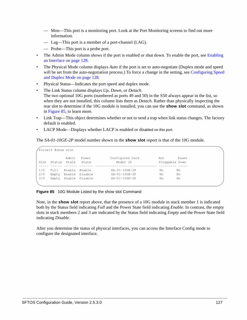
SFTOS Configuration Guide, Version 2.5.3.0 127
— Mon—This port is a monitoring port. Look at the Port Monitoring screens to find out more information.
— Lag—This port is a member of a port-channel (LAG). — Probe—This port is a probe port.
• The Admin Mode column shows if the port is enabled or shut down. To enable the port, see Enabling an Interface on page 128.
• The Physical Mode column displays Auto if the port is set to auto-negotiate (Duplex mode and speed will be set from the auto-negotiation process.) To force a change in the setting, see Configuring Speed and Duplex Mode on page 128.
• Physical Status—Indicates the port speed and duplex mode. • The Link Status column displays Up, Down, or Detach.
The two optional 10G ports (numbered as ports 49 and 50) in the S50 always appear in the list, so when they are not installed, this column lists them as Detach. Rather than physically inspecting the rear slot to determine if the 10G module is installed, you can use the show slot command, as shown in Figure 85, to learn more.
• Link Trap—This object determines whether or not to send a trap when link status changes. The factory default is enabled.
• LACP Mode—Displays whether LACP is enabled or disabled on this port.
The SA-01-10GE-2P model number shown in the show slot report is that of the 10G module.
Figure 85 10G Module Listed by the show slot Command
Note, in the show slot report above, that the presence of a 10G module in stack member 1 is indicated both by the Status field indicating Full and the Power State field indicating Enable. In contrast, the empty slots in stack members 2 and 3 are indicated by the Status field indicating Empty and the Power State field indicating Disable.
After you determine the status of physical interfaces, you can access the Interface Config mode to configure the designated interface.
Force10 #show slot
Admin Power Configured Card Hot PowerSlot Status State State Model ID Pluggable Down----- ------ ------- ------- -------------------------------- --------- -----1/0 Full Enable Enable SA-01-10GE-2P No No2/0 Empty Enable Disable SA-01-10GE-2P No No3/0 Empty Enable Disable SA-01-10GE-2P No No

128
Enabling an Interface
Ports are shut down by default. To enable them, you can do so in bulk mode or per port. For more on bulk configuration, see Bulk Configuration on page 134.
To enable an individual port, use the following sequence of commands:
Configuring Speed and Duplex Mode
As stated above, ports are set by default to auto-negotiate their speed and duplex mode. While you are still in Interface Config mode, you can use the following commands to manually set the speed and duplex mode. (See also Bulk Configuration on page 134.)
Step Command Syntax Command Mode Purpose
1 interface unit/slot/port
Global Config To access the Interface Config mode for the selected port, enter the keyword interface followed by the port number in unit/slot/port format. For example, to configure port 4 on stack member 2, enter interface 2/0/4.
2 no shutdown Interface Config Enable the selected interface.
Step Command Syntax Command Mode Purpose
1 no auto-negotiate Interface Config Disable auto-negotiation on the selected port.
2 speed {{10 | 100 | 1000} {half-duplex | full-duplex}}
Interface Config Manually set the speed and duplex mode on the selected port. For example, you would do this if your port is to be connected to a port that does not support auto-negotiation. Note: The 10G ports that are in the optional rear module of the S50 do not support the speed command or the no auto-negotiate command. You must let them auto-negotiate their connections.
3 exit Interface Config Exit to the Global Config mode.
4 exit Global Config Exit to the Privileged Exec mode.
5 show port unit/slot/port
Privileged Exec Verify that the port is enabled and that the speed is set. See Figure 86.
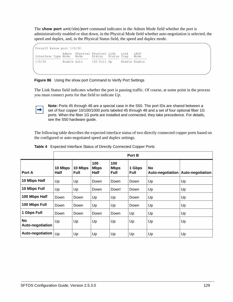
SFTOS Configuration Guide, Version 2.5.3.0 129
The show port unit/slot/port command indicates in the Admin Mode field whether the port is administratively enabled or shut down, in the Physical Mode field whether auto-negotiation is selected, the speed and duplex, and, in the Physical Status field, the speed and duplex mode.
Figure 86 Using the show port Command to Verify Port Settings
The Link Status field indicates whether the port is passing traffic. Of course, at some point in the process you must connect ports for that field to indicate Up.
The following table describes the expected interface status of two directly connected copper ports based on the configured or auto-negotiated speed and duplex settings.
Note: Ports 45 through 48 are a special case in the S50. The port IDs are shared between a set of four copper 10/100/1000 ports labeled 45 through 48 and a set of four optional fiber 1G ports. When the fiber 1G ports are installed and connected, they take precedence. For details, see the S50 hardware guide.
Table 4 Expected Interface Status of Directly Connected Copper Ports
Port B
Port A10 Mbps Half
10 Mbps Full
100 Mbps Half
100 Mbps Full
1 Gbps Full
No Auto-negotiation Auto-negotiation
10 Mbps Half Up Up Down Down Down Up Up
10 Mbps Full Up Up Down Down‘ Down Up Up
100 Mbps Half Down Down Up Up Down Up Up
100 Mbps Full Down Down Up Up Down Up Up
1 Gbps Full Down Down Down Down Up Up Up
No Auto-negotiation
Up Up Up Up Up Up Up
Auto-negotiation Up Up Up Up Up Up Up
Force10 #show port 1/0/30
Admin Physical Physical Link Link LACP Interface Type Mode Mode Status Status Trap Mode -------------- ------ ------- -------- ------ ------ ------- 1/0/30 Enable Auto 100 Full Up Enable Enable

130
The following table describes the expected interface status of two directly connected fiber ports based on the configured or auto-negotiated speed and duplex settings. The fiber ports support only auto-negotiation or 1 Gbps full-duplex.
Configuring Layer 3 Mode
To enable Layer 3 on a port, you assign an IP address to the port. First, inspect the port list to see what IP addresses have been assigned. See Viewing Layer 3 Interface Information on page 125.
By assigning an IP address to a physical interface, you place it in Layer 3 mode. You must also enable routing at the system level and on the interface. Routed traffic now passes through the interface, and you can configure routing protocols on that interface. For details, see Layer 3 Routing on page 255.
Clearing Interface Counters
The counters in the report generated by the show interfaces command can be reset by the following command. This command does not clear the counters captured by any SNMP program.
Table 5 Expected Interface Status of Directly Connected Fiber Ports
Port B
Port A 1 Gbps Full No Auto-negotiation Auto-negotiation
1 Gbps Full Up Up Up
No Auto-negotiation Up Up Down
Auto-negotiation Up Down Up
Note: Layer 3 (routing) in SFTOS requires the Routing Package (Layer 3 Package) of SFTOS.
Command Syntax Command Mode Purpose
clear counters [unit/slot/port | all]
Privileged Exec Without an interface specified, the command clears counters for all ports.With an interface specified, the command clears counters for that interface only.When you use the keyword all, the command clears counters for the entire switch.

SFTOS Configuration Guide, Version 2.5.3.0 131
When you enter the clear counters command, the CLI prompts you to confirm that you want SFTOS to clear the type of counters that you specified. The three options and responses are shown in Figure 87.
Figure 87 Clearing Counters: Example of Using the clear counters Command
Enabling Power over Ethernet Ports (PoE)
SFTOS 2.5.1 introduces support for Power over Ethernet (PoE) functionality for the S50V switch.
PoE provides the ability to transmit both electrical power and data to remote devices over standard twisted-pair cable. SFTOS support for PoE conforms to IEEE 802.3af, which defines a standard to deliver power over Ethernet cables.
All 48 physical copper interfaces on the S50V have the capability to provide power. Some of the salient features are as follows:
• The total power budget for the switch is 360 watts, although the current power supply limits the actual power available to 320 watts, depending on voltage and other factors. Each port can provide 20 watts maximum, subject to the power budget, voltage, and power priority and power limit settings.
• Legacy devices, as well as powered devices specifically compliant with IEEE 802.3af, are supported.• When the power budget is exceeded, the next port attempting to power up causes the currently enabled
port with the lowest priority to shut down if the port attempting to power up has a higher PoE priority.• Support for PoE is provided in the CLI,as well as SNMP. • SNMP support is through the Power-Ethernet MIB (POWER-ETHERNET-MIB) and the Force10
SFTOS-POWER-ETHERNET-MIB for snmpwalk.• Syslog messages are provided for PoE events.
While each of the 48 physical copper interfaces of the S50V can provide power to attached PoE-compliant powered devices, the total PoE power budget cannot provide all ports, at the same time, the 15.4 watts specified by IEEE 802.3af.
Force10 #clear counters 1/0/1
Are you sure you want to clear the port stats? (y/n)y
Port Stats Cleared.
Force10 #clear counters all
Are you sure you want to clear ALL port stats? (y/n)y
ALL Port Stats Cleared.
Force10 #clear counters
Are you sure you want to clear the switch stats? (y/n)y
Switch Stats Cleared.
Force10 #

132
If you connect powered devices to all 48 ports, they can all work at once if their total draw is less than 320 watts. In order to support powered devices that require more power, the S50V uses, by default, a first-come, first-serve method of allocating power.
You can override the default power allocation method by using the CLI to prioritize the delivery of power to the ports. When the power budget is exceeded, the next port attempting to power up causes the port with the lowest priority to stop delivering power, to allow higher priority ports to deliver power.
In any case, even if a connected device is not currently drawing power, the port can stay up and pass data. Conversely, if the port is administratively down (no shut) or the link goes down, the port can continue to supply power (no traffic will flow through the port).
The commands are (For details on command syntax, see the PoE section of the System Configuration chapter in the SFTOS Command Reference):
• inlinepower {disable | enable}unit-id: In Global Config mode, enable or disable the PoE feature for a specified switch in an S-Series stack. By default, PoE is enabled.
• inlinepower threshold 0-100 unit-id: In Global Config mode, configure the percentage of the PoE power budget allotted for a specified switch in the S-Series stack. See Figure 89.
• inlinepower admin {off | auto}: In Interface Config mode, enable or disable the Power over Ethernet (PoE) feature on a particular port. By default, PoE is enabled (auto) on all ports. You need only connect a PoE-compliant powered device to any copper port for it to receive power, subject to other constraints, such as the following command.
• inlinepower priority {critical | high | low}: In Interface Config mode, configure the priority of a port in terms of its access to power. By default, the priority of a port is set to low. which allows it to receive power as long as other ports with higher priorities do not exceed the power budget.
Further, power is supplied according to the physical order of the ports having a particular priority, with port 1/0/1 having the highest priority and 1/0/48 will having the lowest. So, for example, if ports 1/0/1 and 1/0/48 are drawing power and are set to low priority when a higher priority device comes online, port 1/0/48 will be the first to lose power.
• inlinepower limit 0-20: In Interface Config mode, configure the power limit of the selected port (the number of watts available to it if PoE is enabled and other ports do not have higher priority access to the power budget).
• inlinepower type type-string: In Interface Config mode, enter a power profile description of the port. See inlinepower type on page 151. Note that this does not affect the Class value that is displayed in the following commands. The S50V learns the Class value from the powered device. Those values are in the IEEE802.3af specification.
• show inlinepower [all]: In Privileged Exec mode, display PoE status information for one port or all ports in the switch. See Figure 88.
• show inlinepower: In User mode, display the status for all switches in a stack that support PoE. See Figure 89.

SFTOS Configuration Guide, Version 2.5.3.0 133
Figure 88 Sample of Output of show inlinepower Command for a Switch
Status field: In Figure 88, the sample output shows the Status of “Searching” for most ports. Those ports are not connected to powered devices, but they have been left in their default PoE state of enabled.
Class field: As mentioned above, the S50V learns the Class value, as displayed in Figure 88, from the device connected to the port, based on the values in the IEEE802.3af specification; 0 is displayed if the value cannot be learned from device. The S50V allows the connected device to draw power as required. The Class value does not play a role in power allocation.
Limit field: The Limit value displayed in Figure 88 is 18 watts by default. You can use the inlinepower limit command to set a higher (up to 20 watts) or lower limit. If overall power demand is not a constraint, the switch will allow the powered device to draw up to 1 watt more than the configured limit.
Threshold field: Figure 89 shows the PoE status for each unit in the stack. The value in the Threshold field is controlled by the inlinepower threshold command. This command can be used for controlling the total power demand on a common resource or for controlling other factors, such as heat buildup, related to the power use. This command does not spread a power budget across units in a stack. Instead, it simply limits the power budget to some percentage of the theoretical maximum of 360 watts. So, for example, if you set the value at 80, which is the default, the power budget would be 288 watts.
Figure 89 Example Output of show inlinepower Command for a Stack
Force10-S50V >show inlinepower all
Slot Admin OutputPort Type Mode Class Priority Power Limit Status------ --------------- ------- ----- --------- ------ ----- ---------1/0/1 Enable 0 Low 0.000 18 Searching1/0/2 Enable 0 Low 0.000 18 Searching1/0/3 Enable 0 Low 0.000 18 Searching1/0/4 Enable 0 Low 0.000 18 Searching1/0/5 Enable 0 Low 0.000 18 Searching1/0/6 Enable 0 Low 0.000 18 Searching1/0/7 Enable 0 Low 0.000 18 Searching1/0/8 Enable 0 Low 0.000 18 Searching1/0/9 Enable 0 Low 0.000 18 Searching1/0/10 Enable 0 Low 1.3 16 Delivering Power!-------------output deleted----------!
Force10-S50V >show inlinepower
Unit Status Power(W) Consumption(W) Usage(%) Threshold(%) Trap---- ------ -------- -------------- -------- ------------ ----1 Auto 360 22 6.11 100 enable 2 Auto 360 22 6.11 100 enable

134
Bulk ConfigurationBulk configuration means configuring groups of interfaces (physical or logical) with the same command(s).
You have these bulk configuration options:
• Global: Make system-level changes in the Global Config mode. For example, to enable all ports, enter no shutdown all in Global Config mode. You can then disable certain ports in the Interface Config mode.
• Interface Config mode: SFTOS 2.5.1 introduced the ability to configure a range of ports with the tagged and untagged commands. You can use those commands from both the Interface Config and Interface Range modes.
• Interface Range mode: Select one or more sequences of interfaces — ports or logical interfaces (VLAN or LAG) — with the interface range command, to configure with the same settings. For example, see Figure 90 and Figure 91 on page 135.
Using Interface Range Mode
An interface range is a user-selected set of interfaces — ports, VLANs, or port channels — to which you can apply the same configuration change. If you have a stack of S50s, the list of ports in the interface range can include more than one stack member.
There must be at least one valid interface within the range. Bulk configuration excludes from configuration any non-existing interfaces from an interface range. A default VLAN may be configured only if the interface range being configured consists of only VLAN ports.
In combination with the parameter values you include, the interface range command creates the interface range and accesses the Interface Range mode, where you can execute the commands that are applied to that range of interfaces.
The interface range prompt offers the interface (with slot and port information) for valid interfaces. The maximum size of an interface range prompt is 32. If the prompt size exceeds this maximum, it displays (...) at the end of the output.
The System Configuration chapter in the SFTOS Command Reference provides syntax details on the commands used in the Interface Range mode.
See the following section, Bulk Configuration Examples on page 135, for more on bulk configuration. See also, in this guide, the IEEE 802.1Q VLANs chapter (VLANs on page 215) and the section Using the Interface Range mode on page 182 in the LAG chapter.
Note: When creating an interface range, interfaces appear in the order they were entered and are not sorted.

SFTOS Configuration Guide, Version 2.5.3.0 135
Bulk Configuration Examples
The following examples are of using the interface range command for bulk configuration.
Configure a single range
In this example, the interface range ethernet range command was used to select ports 1 through 23 on stack member 5. Then, the no shutdown command enabled all of those ports.
Figure 90 Using Bulk Configuration on a Single Range
Note that spaces are not allowed around hyphens when specifying the range.
The resulting prompt includes interface types with slot/port information for valid interfaces, in this case (conf-if-range-et-5/0/1-5/0/23)#. The prompt allows for a maximum of 32 characters. If the bulk configuration exceeds 32 characters, it is represented by an ellipsis ( ... ).
Configure multiple ranges
In this example, the interface range ethernet range command was used to select multiple ranges in order to configure the speed of the specified range of ports.
Figure 91 Using Multiple Ranges
Note that spaces are also not allowed around commas when specifying the range.
If the interface range command specifies multiple port ranges, the resulting prompt displays the low and high ends of the range. Similarly, if overlapping port ranges are specified, the port range is extended to the smallest start port and the biggest end port.
Force10 (config)#interface range ethernet 5/0/1-5/0/23Force10 (config-if-range-et-5/0/1-5/0/23)#no shutdownForce10 (config-if-range-et-5/0/1-5/0/23)#
Force10 (conf)#interface range ethernet 2/0/1-2/0/10,3/0/1-3/0/10Force10 (conf-if-range-et-2/0/1-3/0/10)#speed 100 full-duplex

136

SFTOS Configuration Guide, Version 2.5.3.0 137
This chapter describes how to configure the S-Series to serve as a DHCP/BootP relay agent or a DHCP server.
This chapter contains the following sections:
• Protocol Overview• Configuring the Switch as a DHCP Server on page 138• Using the Switch as a BootP/DHCP Relay Agent on page 140• Configuration Example — DHCP Server and Relay Agent on page 142
DHCP CommandsThe SFTOS Command Reference contains the following DHCP commands:
• DHCP server function — Chapter 11, DHCP Server Commands• DHCP/BootP relay agent function — Chapter 20, Routing Commands
Protocol OverviewSFTOS support for DHCP is based on the following RFCs. For DHCP details beyond this document, consult those RFCs:
• RFC 2131: DHCP• RFC 2132: DHCP Options and BootP Vendor Extensions• RFC 1534: Interoperation between DHCP and BootP• RFC 1542: Clarifications and Extensions for the BootP• RFC 2241: DHCP Options for Novell Directory Services• RFC 2242: Netware/IP Domain Name and Information
Chapter 7 DHCP
Note: The S-Series switch can only act as a DHCP/BootP relay agent when the Layer 3 Package of SFTOS is installed.

138
Table 6 describes the messages that are exchanged between a DHCP client and server.
Table 6 Messages Exchanged between a DHCP Client and Server
Configuring the Switch as a DHCP ServerImportant Points to Remember• The S-Series supports a maximum of 16 pools. If you attempt to configure more than 16 pools, the
switch prints the following error message: Could not create DHCP pool.
• Up to 256 leases can be offered. • To create a partial scope, use the ip dhcp excluded-address ip address command.• When configuring VLANs, SFTOS automatically matches the requests coming from a particular
subnet to the pool with that subnet and assigns an IP address accordingly. For example, it will recognize that a request has been received from a host on VLAN 10, which is using addresses on the 10.10.10.0 network, and automatically assign it an address from the 10.10.10.0 pool.
Configuration Task List• Configuring a DHCP address pool (required) on page 139• Excluding IP addresses (optional) on page 139• Enabling the SFTOS DHCP Server feature (required) on page 139
Reference Message Use
0x01 DHCPDISCOVER The client is looking for available DHCP servers.
0x02 DHCPOFFER The server response to the client’s DHCPDISCOVER message.
0x03 DHCPREQUEST The client broadcasts to the server, requesting offered parameters from one server specifically, as defined in the packet.
0x04 DHCPDECLINE The client-to-server communication, indicating that the network address is already in use.
0x05 DHCPACK The server-to-client communication with configuration parameters, including committed network address.
0x06 DHCPNAK The server-to-client communication, refusing the request for configuration parameter.
0x07 DHCPRELEASE The client-to-server communication, relinquishing network address and canceling remaining leases.
0x08 DHCPINFORM The client-to-server communication, asking for only local configuration parameters that the client already has externally configured as an address.

SFTOS Configuration Guide, Version 2.5.3.0 139
Configuring a DHCP address pool (required)
You can configure a DHCP address pool with a name that is a symbolic string (such as "Engineering") or an integer (such as 0). Configuring a DHCP address pool also places you in DHCP pool configuration mode, as identified by the “(config-dhcp)#” prompt, from which you can configure pool parameters (for example, the IP subnet number and default router list). To configure a DHCP address pool, complete the following required steps. For details on these commands, see the DHCP Server Commands chapter in the SFTOS Command Reference.
Excluding IP addresses (optional)
The DHCP server assumes that all IP addresses in a DHCP address pool subnet are available for assigning to DHCP clients. You must specify the IP address that the DHCP server should not assign to clients.
Use the ip dhcp excluded-address lowaddress [highaddress] command in Global Config mode to create partial scopes.
Enabling the SFTOS DHCP Server feature (required)
By default, the SFTOS DHCP Server feature is disabled on the S-Series. Use the service dhcp command in Global Config mode to enable the SFTOS DHCP Server feature:
Step Command Mode Purpose
1 ip dhcp pool poolname
Global Config Creates a name for the DHCP server address pool and places you in DHCP pool configuration mode (identified by the “config-dhcp#” prompt).
2 network ip_address mask
DHCP Pool Config Configures an IP address and subnet mask for this DHCP address pool, which contains the range of available IP addresses that the DHCP server may assign to clients.
3 default-router address1 [address2...address8]
DHCP Pool Config Specifies the default router list for a DHCP client. After a DHCP client boots, the client begins sending packets to its default router. The IP address of the default router must be on the same subnet as the client.
4 dns-server address1 [address2...address8]
DHCP Pool Config Specifies the IP address of a DNS server that is available to a DHCP client. A single IP address can be configured.Note: If more than one address is configured, SFTOS overwrites the configuration with the most recent address.

140
Verifying the DHCP Server ConfigurationUse the show ip dhcp server statistics command to verify the DHCP server configuration:
Figure 92 Using the show ip dhcp server statistics Command
Using the Switch as a BootP/DHCP Relay AgentThe S-Series also can serve as a BootP/DHCP relay agent, forwarding DHCP packets between clients and a DHCP server (you can only use the switch as a relay agent to one DHCP server). This section describes the concepts and tasks needed to configure the DHCP relay agent.
DHCP Relay Agent Overview
When the switch is configured to act as a DHCP relay agent, it forwards DHCP client broadcasted requests to a DHCP server on another broadcast domain (Layer 3 network). These broadcasted requests from a DHCP client use a destination IP address of 255.255.255.255 (all networks broadcast address).The DHCP relay agent process is as follows:
1. The DHCP relay agent makes these two changes to the in-bound DHCP packet:
a The relay agent appends its own IP address to the source IP address of the DHCP frames going to the DHCP server.
b The relay agent populates the Gateway IP address field with the IP address of the interface on which the DHCP message is received from the client.
2. The relay agent forwards the rewritten DHCP request on behalf of a DHCP client to the DHCP server.
3. The DHCP server unicasts a reply to the DHCP relay agent, using the Gateway IP address field to determine the subnet from which the DHCPDISCOVER, DHCPREQUEST, or DHCPINFORM message originated.
4. The relay agent forwards the packet to the DHCP client.
Force10 #show ip dhcp server statistics
Automatic Bindings............................. 0Expired Bindings............................... 0Malformed Bindings............................. 0 Messages Received---------- ----------DHCP DISCOVER.................................. 5DHCP REQUEST................................... 0DHCP DECLINE................................... 0DHCP RELEASE................................... 0DHCP INFORM.................................... 0 Messages Sent---------- ------DHCP OFFER..................................... 0DHCP ACK....................................... 0DHCP NACK...................................... 0

SFTOS Configuration Guide, Version 2.5.3.0 141
Configuring the Switch as a DHCP Relay Agent
Implement the DHCP relay agent feature with bootpdhcprelay commands, all in Global Config mode. For details on these commands, see the Bootp/DHCP Relay Commands section of the Routing Commands chapter in the SFTOS Command Reference.
Verifying the DHCP Relay Agent Configuration
Use the show bootpdhcprelay command to verify the DHCP Relay Agent configuration, as shown in Figure 93.
Figure 93 Using the show bootpdhcprelay Command
Step Command Mode Purpose
1 bootpdhcprelay serverip ip-address
Global Config Enter the IP address of the DHCP server.
2 bootpdhcprelay enable
Global Config Enable forwarding of BootP/DHCP requests. By default, the DHCP relay agent feature is disabled.
3 bootpdhcprelay maxhopcount 1-16
Global Config (Optional) Configure the maximum allowable relay agent hops. The parameter has a range of 1 to 16. By default, the packet will be forwarded a limit of four hops.
4 bootpdhcprelay minwaittime 0-100
Global Config (Optional) Configure the minimum wait time in seconds for BootP/DHCP relay requests. When the BootP relay agent receives a BOOTREQUEST message, it may use the seconds-since-client-began-booting field of the request as a factor in deciding whether to relay the request or not. The parameter has a range of 0 to 100 seconds. The default value is 0 seconds.
Force10 #show bootpdhcprelay
Maximum Hop Count.............................. 4Minimum Wait Time(Seconds)..................... 0Admin Mode..................................... EnableServer IP Address.............................. 10.16.1.2Circuit Id Option Mode......................... DisableRequests Received.............................. 0Requests Relayed............................... 0Packets Discarded.............................. 0

142
Configuration Example — DHCP Server and Relay AgentIn the following example, a DHCP address pool is created for PCs on the 10.1.3.0 network. In this pool, all addresses except the excluded address, which is the router’s IP address, are available to the DHCP server for assigning to clients.
Figure 94 Diagram of Two Switches Acting as DHCP Server and Relay Agent
Configure switch “S50-B”, from the diagram above, as a DHCP server, as shown in Figure 95.
Figure 95 Example of Configuring a Switch as a DHCP server
Configure switch S50-A and S50-B (Figure 94), as the DHCP relay agent and DHCP server, respectively.
Figure 96 Example of Configuring a Switch as a DHCP relay agent
S50-B #configS50-B (Config)#service dhcpS50-B (Config)#ip dhcp pool Pool1S50-B (config-dhcp)#network 10.1.3.0 255.255.255.0S50-B (config-dhcp)#default-router 10.1.3.1S50-B (config-dhcp)#dns-server 192.168.1.90S50-B (config-dhcp)#exitS50-B (Config)#ip dhcp excluded-address 10.1.3.1 10.1.3.11S50-B (Config)#ip routingS50-B (Config)#interface 1/0/1S50-B (Config)#routingS50-B (Interface 1/0/1)#ip address 10.1.1.10 255.255.255.0S50-B (Interface 1/0/1)#exitS50-B (Config)#ip route 10.1.3.0 255.255.255.0 10.1.1.1!--Using a static route to ensure the DHCP server can ping 10.1.3.1.--!S50-B (Config)#exit
S50-A #configS50-A (Config)#ip routingS50-A (Config)#bootpdhcprelay serverip 10.1.1.10S50-A (Config)#bootpdhcprelay enableS50-A (Config)#interface 1/0/2S50-A (Interface 1/0/2)#ip address 10.1.3.1S50-A (Interface 1/0/2)#exitS50-A (Config)#interface 1/0/1S50-A (Interface 1/0/1)#ip address 10.1.1.1

SFTOS Configuration Guide, Version 2.5.3.0 143
This chapter contains the following major sections:
• Choosing a TACACS+ Server and Authentication Method• Configuring TACACS+ Server Connection Options on page 145• Configuring a RADIUS Connection on page 146• Enabling Secure Management with SSH on page 149
SFTOS supports several user-access security methods to the switch, including local (see Creating a User and Password on page 45), port security (IEEE 802.1X) through RADIUS and Terminal Access Controller Access Control System (TACACS+), and encrypted transport session (between the management station and switch) using Secure Shell (SSH). This chapter describes how to configure each of those methods.
For more on port security configuration (including MD5), see the Security deck of the S-Series Training slides, which are on the S-Series Documentation CD-ROM.
Choosing a TACACS+ Server and Authentication MethodTo use TACACS+ to authenticate users, you specify at least one TACACS+ server with which the S-Series will communicate, then identify TACACS+ as one of your authentication methods. To select TACACS as the login authentication method, use the following command sequence:
Chapter 8 Providing User Access Security
Step Command SyntaxCommand Mode Purpose
1 tacacs-server host ip-address Global Config Configure a TACACS+ server host. Enter the IP address or host name of the TACACS+ server. You can use this command multiple times to configure multiple TACACS+ server hosts.
1 exit TACACS Config
Return to Global Config mode. Alternatively, while you are still in TACACS Config mode, you can set values for server-specific parameters, such as priority, key, and timeout. See Configuring TACACS+ Server Connection Options on page 145.

144
TACACS would generally not be the last method specified, in order to avoid a situation where the final authentication option depends on a server that might be offline. Generally, you would specify local as the final method. For example, in the command string “authentication login listone tacacs local”, “listone” is the name given to the method list, followed by the selected sequence of authentication methods—“tacacs” and then “local”. For details on setting local passwords, see Creating a User and Password on page 45.
TACACS+ includes a group of configurable settings that you can also leave in their default settings. You can configure some global settings (for all TACACS+ servers), or you can configure settings at the individual server level. See the Security chapter in the FTOS Command Line Interface Reference for details on global settings. See the following section, Configuring TACACS+ Server Connection Options on page 145, for more on configuring one host.
To specify the IP address of the TACACS host, use the tacacs-server host command in the Global Config mode, as shown here. In this example, the user then changes the local timeout to 5 seconds:
Figure 97 Setting the IP Address of a TACACS+ Server
Figure 98 Display Settings for TACACS+ Server Connections
2 authentication login listname {method1 [method2 [method3]]}
Global Config Create a method-list name and specify that TACACS is one method for login authentication.
3 users defaultlogin listname Global Config Assign a method list to use to authenticate non-configured users when they attempt to log in to the system.
4 show tacacs Privileged Exec
Verify the configuration and status of TACACS servers (See Figure 98).
5 show authentication Privileged Exec
Display the ordered authentication methods for all authentication login lists.
Step Command SyntaxCommand Mode Purpose
Force10#configForce10 (Config)#tacacs-server host 1.1.1.1Force10 (Tacacs)#timeout 5Force10 (Tacacs)#exitForce10 (Config)#
Force10 #show tacacs
Global Timeout: 5
IP address Port Timeout Priority--------------- ----- ------- --------10.10.10.226 49 Global 0 10.16.1.58 49 Global 0
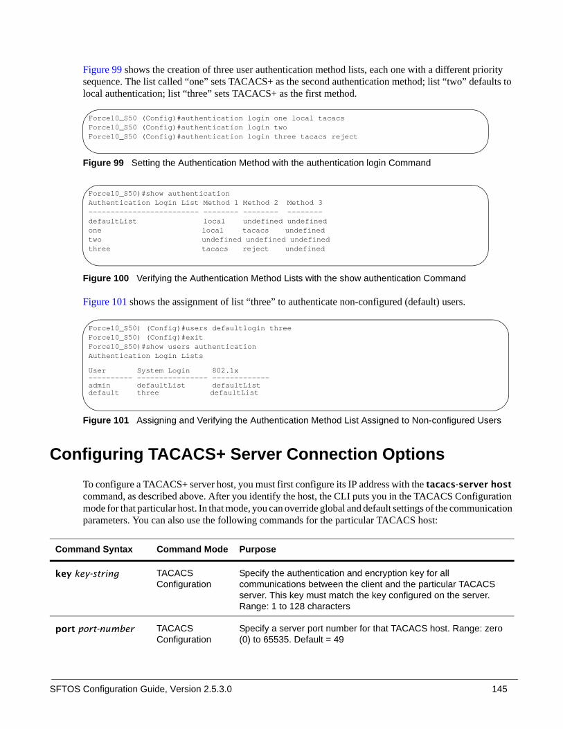
SFTOS Configuration Guide, Version 2.5.3.0 145
Figure 99 shows the creation of three user authentication method lists, each one with a different priority sequence. The list called “one” sets TACACS+ as the second authentication method; list “two” defaults to local authentication; list “three” sets TACACS+ as the first method.
Figure 99 Setting the Authentication Method with the authentication login Command
Figure 100 Verifying the Authentication Method Lists with the show authentication Command
Figure 101 shows the assignment of list “three” to authenticate non-configured (default) users.
Figure 101 Assigning and Verifying the Authentication Method List Assigned to Non-configured Users
Configuring TACACS+ Server Connection OptionsTo configure a TACACS+ server host, you must first configure its IP address with the tacacs-server host command, as described above. After you identify the host, the CLI puts you in the TACACS Configuration mode for that particular host. In that mode, you can override global and default settings of the communication parameters. You can also use the following commands for the particular TACACS host:
Command Syntax Command Mode Purpose
key key-string TACACS Configuration
Specify the authentication and encryption key for all communications between the client and the particular TACACS server. This key must match the key configured on the server. Range: 1 to 128 characters
port port-number TACACS Configuration
Specify a server port number for that TACACS host. Range: zero (0) to 65535. Default = 49
Force10_S50 (Config)#authentication login one local tacacsForce10_S50 (Config)#authentication login twoForce10_S50 (Config)#authentication login three tacacs reject
Force10_S50)#show authenticationAuthentication Login List Method 1 Method 2 Method 3 ------------------------- -------- -------- -------- defaultList local undefined undefined one local tacacs undefined two undefined undefined undefinedthree tacacs reject undefined
Force10_S50) (Config)#users defaultlogin threeForce10_S50) (Config)#exitForce10_S50)#show users authenticationAuthentication Login Lists
User System Login 802.1x ---------- ---------------- ------------- admin defaultList defaultList default three defaultList
146
To delete a TACACS+ server host, use the no tacacs-server host ip-address command.
Configuring a RADIUS Connection Remote Authentication Dial-In User Service (RADIUS) is another means of port-based network access control. The switch acts as an intermediary to a RADIUS server, which provides both an authentication and an accounting function to maintain data on service usages.
Under RFC 2866, an extension was added to the RADIUS protocol giving the client the ability to deliver accounting information about a user to an accounting server. Exchanges to the accounting server follow similar guidelines to that of an authentication server, but the flows are much simpler.
At the start of service for a user, the RADIUS client configured to use accounting sends an accounting start packet specifying the type of service that it will deliver. Once the server responds with an acknowledgement, the client periodically transmits accounting data. At the end of service delivery, the client sends an accounting stop packet allowing the server to update specified statistics. The server again responds with an acknowledgement.
Setting up a connection to a server running Remote Authentication Dial-In User Service (RADIUS) is basically the same as the TACACS+ procedure described above (see Choosing a TACACS+ Server and Authentication Method on page 143 and Configuring TACACS+ Server Connection Options on page 145), where you identify the address of the authentication server and you specify an ordered set of authentication methods. The following RADIUS commands are documented in the Security chapter of the SFTOS Command Reference:
• radius accounting mode: Enable the RADIUS accounting function.• radius server host: Configure the RADIUS authentication and accounting server.• radius server key: Configure the shared secret between the RADIUS client and the RADIUS
accounting / authentication server.• radius server msgauth: Enable the message authenticator attribute for a specified server.• radius server primary: Configure the primary RADIUS authentication server for this RADIUS
client.• radius server retransmit: Set the maximum number of times a request packet is re-transmitted
when no response is received from the RADIUS server.• radius server timeout: Set the timeout value (in seconds) after which a request must be
retransmitted to the RADIUS server if no response is received.
priority priority TACACS Configuration
Determine the order in which the server will be used with multiple authentication servers, with 0 being the highest priority. Range: zero (0) to 65535. Default = 0
timeout TACACS Configuration
Range: 1 to 30 seconds. Default = global setting
Command Syntax Command Mode Purpose

SFTOS Configuration Guide, Version 2.5.3.0 147
• show radius: to display the various RADIUS configuration items for the switch as well as the configured RADIUS servers.
• show radius accounting statistics: Display the configured RADIUS accounting mode, accounting server, and the statistics for the configured accounting server.
• show radius statistics (authentication): Display the statistics for RADIUS or configured server.
Using the CLI to Configure Access through RADIUS
The following example configuration sequence configures:
• A single RADIUS server at IP address 10.10.10.10, to be used for both authentication and accounting• The RADIUS server shared secret for both authentication and accounting to be the word “secret”• An authentication list called “radiusList”, specifying RADIUS as the only authentication method• radiusList method associated with the 802.1x default login (for non-configured users for 802.1x port
security). 802.1x port-based access control is enabled for the system.• Interface 1/0/1 in force-authorized mode, because this is where the RADIUS server and protected
network resources are located
If a user, or supplicant, attempts to communicate through the switch on any interface except port 1/0/1, the system challenges the supplicant for login credentials. The system encrypts the provided information and transmits it to the RADIUS server. If the RADIUS server grants access, the system sets the 802.1x port state of the interface to authorized and the supplicant is able to access network resources.
Figure 102 RADIUS Topology

148
Figure 103 Configuration Example for RADIUS
Figure 104 and Figure 105 show a setup with two RADIUS servers as authentication servers. The command radius server key auth 10.10.10.10 invokes a request for “secret1” to be the shared secret word for the RADIUS server at IP address 10.10.10.10 , while radius server key auth 11.11.11.11 invokes a request for “secret2” as the shared secret for the second RADIUS server. The radius server primary command sets the first RADIUS server as the primary authenticator, and the rest of the configuration is as was done above.
Figure 104 Topology with Two RADIUS Servers
Force10 #configForce10 (Config)#Force10 (Config)#radius server host auth 10.10.10.10Force10 (Config)#radius server key auth 10.10.10.10Enter secret (16 characters max):******Re-enter secret:******Force10 (Config)#radius server host acct 10.10.10.10Force10 (Config)#radius server key acct 10.10.10.10Enter secret (16 characters max):******Re-enter secret:******Force10 (Config)#radius accounting modeForce10 (Config)#authentication login radiusList radiusForce10 (Config)#dot1x defaultlogin radiusListForce10 (Config)#dot1x system-auth-controlForce10 (Config)#interface 1/0/1Force10 (Interface 1/0/1)#dot1x port-control force-authorizedForce10 (Interface 1/0/1)#exitForce10 (Config)#exit
authentication
accounting

SFTOS Configuration Guide, Version 2.5.3.0 149
Figure 105 Configuration Example for Two RADIUS Servers
Enabling Secure Management with SSH SFTOS supports three ways to provide more secure management access to the switch:
• Interactive login using the Telnet protocol with Secure SHell (SSH) aded for security• SNMP: SNMP includes its own security features.
Secure SHell (SSH) provides secure management through an encrypted transport session between the management station and switch.
Enabling secure management through SSH is a four-step process:
1. Generate the SSH keys certificates offline.
2. Copy the SSH keys certificates to the switch using TFTP.
3. Enable the secure management server (SSH) on the switch.
4. Disable the insecure version of the management server (Telnet).
The SSH keys certificates are in a .zip file that are on the S-Series CD-ROM. You can also get them from your Force10 account team. The .zip file contains two directories—ssh and ssl:
• The ssh directory has example RSA1, RSA2, and DSA keys and a shell script called “generate-keys.sh” that can be used to generate your own SSH keys.
Note: Starting with SFTOS 2.5.1.1, SSH keys are generated automatically when you enable the SSH Server. Skip to Enabling SSH on page 150.
Note: The ssl directory was intended for use in accessing the switch through a Web browser. That functionality is not supported in SFTOS 2.5.2.
Force10 #configForce10 (Config)#radius server host auth 10.10.10.10Force10 (Config)#radius server key auth 10.10.10.10Enter secret (16 characters max):******Re-enter secret:******Force10 (Config)#radius server host auth 11.11.11.11Force10 (Config)#radius server key auth 11.11.11.11Enter secret (16 characters max):******Re-enter secret:******Force10 (Config)#radius server primary 10.10.10.10Force10 (Config)#authentication login radiusList radius localForce10 (Config)#users defaultlogin radiusListForce10 (Config)#exit

150
The scripts provided use OpenSSH (http://www.openssh.org/) for key generation. Other free and commercial tools exist that can provide the same functionality, and you can use them if you like.
For an introduction to the options and commands related to the Telnet and SSH features, see Setting up a Management Connection to the Switch on page 36.
Enabling SSH
Starting with SFTOS 2.5.1.1, you no longer need to generate the SSH keys off-line. Before you enable the SSH server, NVRAM does not contain the keys, as shown (or not shown, in this case) in Figure 106. After you enable the SSH server and the SSH keys are automatically generated, the keys will not be deleted even if SSH is disabled later. See Figure 107 on page 151.
Figure 106 Using dir nvram Command to Inspect NVRAM for SSH Keys
S50-maa-07#dir nvram/DskVol/files>...hpc_broad.cfg 276startup-config 1975image1 8428304log2.bin 262132olog1.txt 0slog0.txt 0boot.dim 49slog1.txt 0olog0.txt 0mmu_buffer.cfg 9920sslt.rnd 1024
Filesystem size 64876544Bytes used 8703680Bytes free 56172864
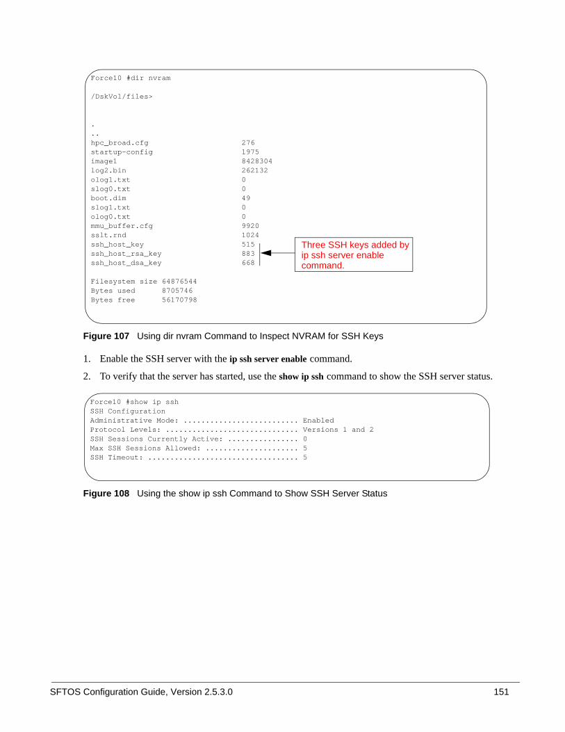
SFTOS Configuration Guide, Version 2.5.3.0 151
Figure 107 Using dir nvram Command to Inspect NVRAM for SSH Keys
1. Enable the SSH server with the ip ssh server enable command.
2. To verify that the server has started, use the show ip ssh command to show the SSH server status.
Figure 108 Using the show ip ssh Command to Show SSH Server Status
Force10 #dir nvram
/DskVol/files>
.
..hpc_broad.cfg 276startup-config 1975image1 8428304log2.bin 262132olog1.txt 0slog0.txt 0boot.dim 49slog1.txt 0olog0.txt 0mmu_buffer.cfg 9920sslt.rnd 1024ssh_host_key 515ssh_host_rsa_key 883ssh_host_dsa_key 668
Filesystem size 64876544Bytes used 8705746Bytes free 56170798
Three SSH keys added byip ssh server enablecommand.
Force10 #show ip sshSSH ConfigurationAdministrative Mode: .......................... EnabledProtocol Levels: .............................. Versions 1 and 2SSH Sessions Currently Active: ................ 0Max SSH Sessions Allowed: ..................... 5SSH Timeout: .................................. 5
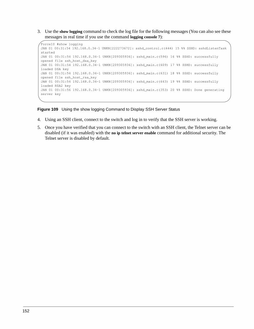
152
3. Use the show logging command to check the log file for the following messages (You can also see these messages in real time if you use the command logging console 7):
Figure 109 Using the show logging Command to Display SSH Server Status
4. Using an SSH client, connect to the switch and log in to verify that the SSH server is working.
5. Once you have verified that you can connect to the switch with an SSH client, the Telnet server can be disabled (if it was enabled) with the no ip telnet server enable command for additional security. The Telnet server is disabled by default.
Force10 #show loggingJAN 01 00:31:54 192.168.0.34-1 UNKN[222273672]: sshd_control.c(444) 15 %% SSHD: sshdListenTask startedJAN 01 00:31:54 192.168.0.34-1 UNKN[209305936]: sshd_main.c(596) 16 %% SSHD: successfully opened file ssh_host_dsa_keyJAN 01 00:31:54 192.168.0.34-1 UNKN[209305936]: sshd_main.c(609) 17 %% SSHD: successfully loaded DSA keyJAN 01 00:31:54 192.168.0.34-1 UNKN[209305936]: sshd_main.c(631) 18 %% SSHD: successfully opened file ssh_host_rsa_keyJAN 01 00:31:54 192.168.0.34-1 UNKN[209305936]: sshd_main.c(643) 19 %% SSHD: successfully loaded RSA2 keyJAN 01 00:31:56 192.168.0.34-1 UNKN[209305936]: sshd_main.c(353) 20 %% SSHD: Done generating server key

SFTOS Configuration Guide, Version 2.5.3.0 153
This chapter discusses the SFTOS implementation of Spanning Tree Protocol (STP), Multiple Spanning Tree Protocol (MSTP), and Rapid Spanning Tree Protocol (RSTP). The chapter contains the following major sections:
• SFTOS STP Switching Features• Spanning Tree Protocol (STP, IEEE 802.1D) on page 154• Rapid Spanning Tree Protocol (RSTP, IEEE 802.1w) on page 155• Multiple Spanning-Tree Protocol (MSTP, IEEE 802.1s) on page 156• Spanning Tree Configuration Tasks on page 159• Setting the STP Version Parameter on page 159• Enabling STP on page 160• MSTP Configuration Example on page 164• Display Spanning Tree Configuration on page 165
SFTOS STP Switching Features• Forwarding, Aging, and Learning• Spanning Tree, IVL and STP per VLAN• IEEE 802.1D — Spanning Tree Protocol (STP)• IEEE 802.1w — Rapid Spanning Tree Protocol (RSTP)• IEEE 802.1s — Multiple Spanning Tree Protocol (MSTP)
Forwarding, Aging, and Learning• Forwarding: At Layer 2, frames are forwarded according to their MAC address.• Aging: SFTOS supports a user-configurable address-aging timeout parameter, defined in IEEE 802.1D.• Learning:
— SFTOS learns and manages MAC addresses, as specified in IEEE 802.1D and IEEE 802.1q.— SFTOS supports Shared VLAN Learning (SVL), although Independent VLAN Learning (IVL) is
the default.
Chapter 9 Spanning Tree
Note: The default spanning tree mode in SFTOS is IEEE 802.1s (MSTP), which is backward-compatible with IEEE 802.1D and IEEE 802.1w. Those standalone legacy modes are also available in SFTOS, as described in Setting the STP Version Parameter on page 159.

154
Spanning Tree Protocol (STP, IEEE 802.1D)When SFTOS is set to run in basic Spanning Tree Protocol (STP) mode, SFTOS conforms to IEEE 802.1D and the RFC 1493 Bridge MIB. A spanning tree algorithm provides path redundancy while preventing undesirable loops in a network:
• SFTOS switching can be configured to run with STP enabled or disabled.• Without STP, a path failure causes a loss of connectivity.• STP allows only one active path at a time between any two network devices, but allows for backup
paths.• When a topology change occurs, accelerated aging is used on the forwarding database(s).
STP allows port costs to be configured as zero, which causes the port to use IEEE 802.1D-recommended values. In addition, per-port Administrative Mode affects sequence when the link comes up:
• Fast mode—listening and learning timers set to two seconds (this is recommended to avoid time-outs during reconfiguration).
• Off/manual mode—port is always in forwarding mode (this is recommended, but only when no loops are possible).
Basic STP (802.1D) CLI Management
Privileged and User Exec Mode CLI commands:
• Display STP settings and parameters for the switch:— show spanning-tree summary
• Display STP settings and parameters for the bridge instance:— show spanning-tree [brief]
Global Config Mode CLI commands:
• [Disable] enable spanning tree for the switch:— [no] spanning-tree
• Set maximum time for discarding STP configuration messages, default 20 seconds:— [no] spanning-tree max-age 6-40
• Set time between STP config messages, default 2 seconds:— [no] spanning-tree hello-time 1-10
• Set time spent in listening and learning, default 15 seconds:— [no] spanning-tree forward-time 4-30
• Set MSTP Max Hops parameter for the common and internal spanning tree:— spanning-tree max-hops 1-127 (default is 20)
• Set Bridge Max Age parameter for the common and internal spanning tree:— spanning-tree max-age 6-40 (default is 20)
• Set the protocol Version parameter to a new value:— spanning-tree forceversion {802.1d | 802.1w | 802.1s}

SFTOS Configuration Guide, Version 2.5.3.0 155
Basic STP CLI Port Management
Privileged and User Exec Mode CLI command:
• Display STP settings and parameters for an interface— show spanning-tree interface unit/slot/port
Global Config Mode CLI command:
• [Disable] enable STP administrative mode for all interfaces— [no] spanning-tree port mode enable all
Interface Config Mode CLI command:
• [Disable] enable STP administrative mode for an interface— [no] spanning-tree port mode enable
For MSTP commands, see Multiple Spanning-Tree Protocol (MSTP, IEEE 802.1s) on page 156. For details on STP commands, see the Spanning Tree chapter in the SFTOS Command Reference.
Rapid Spanning Tree Protocol (RSTP, IEEE 802.1w)The default spanning tree mode in SFTOS is IEEE 802.1s (MSTP), which is backward-compatible with IEEE 802.1D and IEEE 802.1w (Rapid Spanning Tree Protocol — RSTP). SFTOS also supports RSTP as a non-default, stanalone mode. See Setting the STP Version Parameter on page 159.
RSTP provides faster convergence than Spanning Tree Protocol (STP) and interoperability with other switches configured with STP and MSTP.
RSTP Implementation
Port Roles
RSTP adds new port roles to STP. Port roles that forward include:
• Root Port: This is the port that is the closest to the root bridge based on path cost. A bridge sends traffic on this port to the root.
• Designated Port: This is the port that is the closest to the root bridge based on path cost. A bridge receives traffic on this port from others on the segment.
Port roles that do not forward include:
• Alternate Port: This is a port that is an alternate path to the root on a different bridge than the designated bridge.
• Backup Port: This is a port that is an alternate path to the root on the designated bridge.• Disabled Port: This is a port that has no role in RSTP.
156
Port States
RSTP merges states from STP, leaving just three possible operational states. The 802.1D blocking and disabled states are merged into the 802.1w discarding state. The 802.1D learning and listening states are merged into the 802.1w learning state.
Port Costs
RSTP introduces new default port costs.
BPDU Format
RSTP has a unique BPDU format that uses all bits of the Flags field to communicate additional states. The RSTP BPDUs act as a keep-alive between bridges, allowing for significantly faster link failure detection.
Convergence with RSTP
The faster convergence with RSTP results from the use of BPDUs as keep-alives between adjacent switches, which establish the state before passing information to the downstream device. In contrast, the pre-RSTP version of STP uses timers to allow BPDUs to flow from root to all leaves. Non-edge ports stay a set time in listening and learning modes to gather all available BPDU information to decide the port state.
RSTP CLI ManagementRSTP uses the same commands as basic STP (see Basic STP (802.1D) CLI Management on page 154).
Multiple Spanning-Tree Protocol (MSTP, IEEE 802.1s)The default spanning tree mode in SFTOS is IEEE 802.1s (Multiple Spanning-Tree Protocol — MSTP), which is backward-compatible with 802.1D (see Spanning Tree Protocol (STP, IEEE 802.1D) on page 154) and 802.w (see Rapid Spanning Tree Protocol (RSTP, IEEE 802.1w) on page 155).
SFTOS also supports each standalone mode — IEEE 802.1D, IEEE 802.1s, and IEEE 802.1w (see Setting the STP Version Parameter on page 159).
MSTP allows LAN traffic to be channeled over different interfaces. MSTP also allows load balancing without increasing CPU usage.
Rapid reconfiguration minimizes the time to recover from network outages, and increases network availability.

SFTOS Configuration Guide, Version 2.5.3.0 157
Important Points to Remember
MSTP is part of the SFTOS switching package. Either IEEE 802.1D or IEEE 802.1s operates at any given time. The following is the SFTOS implementation of MSTP:
• MSTP instances can only exist within a region.• One Common Instance (CIST) and 32 additional Multiple Instances (MSTIs) are supported.• Each port supports multiple STP states, with one state per instance. Thus, a port can be in the
forwarding state in one instance and blocking in another instance. • MSTP BPDUs appear as normal BPDUs for the CIST while including information for the MSTIs (one
record for each MSTP Instance). The CIST is mapped to Instance 0. • VLANs are associated with one and only one instance of STP. • Multiple VLANs can be associated with an STP instance. • The overall root bridge for 802.1s is calculated in the same way as for 802.1D or 802.1w.• IEEE 802.1s bridges can interoperate with IEEE 802.1D and IEEE 802.1w bridges
MST Regions
A Multiple Spanning Tree region is a collection of MST bridges that share the same VLAN-to-STP instance mappings. They are administratively configured on each MST Bridge in the network.
MST regions are identified by:
• 32-byte alphanumeric configuration name• Two-byte configuration revision number• The mapping of VLAN IDs to STP instance numbers
MST Interactions
Bridge Protocol Data Units (BPDU) considerations:
• MSTP instances can only exist within in a region• MSTP instances never interact outside a region• MSTP BPDUs appear as normal BPDUs for the CIST while including information for the MSTIs (one
record for each MSTP Instance)• The CIST is mapped to Instance 0• Both ends of a link may send BPDUs at the same time, as they may be the designated ports for
different instances
MSTP Standards• Conforms to IEEE 802.1s• Compatible with IEEE 802.1w and IEEE 802.1D• SNMP management via a private MIB, as no standard MIB exists

158
MSTP CLI Management
SFTOS supports Multiple Spanning Tree Protocol (MSTP) by default. The basic STP commands (see Basic STP (802.1D) CLI Management on page 154) applicable to MSTP. In addition to display commands (see Display Spanning Tree Configuration on page 165), SFTOS provides the following commands specific to MSTP:
Command Syntax Command Mode Purpose
[no] spanning-tree msti instance mstid
Global Config Add an MSTP instance to the switch.The instance mstid is a number corresponding to the new instance ID to be added. Range: mstid range of 0 to 63. The maximum number of MSTP instances supported by SFTOS is 4.
[no] spanning-tree msti vlan msti vlanid
Global Config Add an association between an MSTP instance and a VLAN. The VLAN will no longer be associated with the common and internal spanning tree.The msti is a number that corresponds to the desired existing multiple spanning tree instance. The vlanid is an existing VLAN ID.
spanning-tree msti priority mstid 0–61440
Global Config Set the bridge priority for a specific MSTP instance.The instance mstid is a number corresponding to the new instance ID to be added. 0–61440 is the priority value.Range: mstid range of 0 to 63. The priority value is in a range of 0 to 61440, in increments of 4096.
Default: priority = S32768
spanning-tree bpdumigrationcheck {unit/slot/port | all}
Global Config Force a transmission of rapid spanning tree (RSTP) and multiple spanning tree (MSTP) BPDUs. Use the unit/slot/port parameter to transmit a BPDU from a specified interface, or use the all keyword to transmit BPDUs from all interfaces. This command forces the BPDU transmission when you execute it, so the command does not change the system configuration or have a no version.Use the show interface ethernet unit/slot/port command to display BPDU counters. See Figure 125 on page 171.

SFTOS Configuration Guide, Version 2.5.3.0 159
Spanning Tree Configuration Tasks1. Determine if Spanning Tree Protocol (STP) is enabled globally and on ports. See Figure 115 on
page 166 and Figure 117 on page 166.
2. Select an STP operational mode. See Setting the STP Version Parameter on page 159.
3. Start STP: Enable STP globally each on participating switch and enable STP on ports. See Enabling STP on page 160.
4. Verify the global configuration, the interface configuration, and the STP convergence. See Display Spanning Tree Configuration on page 165.
5. (OPTIONAL) Influence the STP topology. See Influencing the Spanning Tree Topology on page 161
6. (OPTIONAL) Change global STP operational parameters. See Changing Spanning Tree Global Parameters on page 162.
7. (OPTIONAL) Enable an edge port. See Enabling an Edge Port on page 163.
8. (OPTIONAL) Manage MSTP behavior. See MSTP Configuration Example on page 164.
Setting the STP Version Parameter
The Global Config mode command spanning-tree forceversion {802.1d | 802.1w | 802.1s} sets the protocol Version parameter to a new value. The Force Protocol Version can be one of the following:
• 802.1d - STP BPDUs are transmitted rather than MST BPDUs (IEEE 802.1D functionality supported)• 802.1w - RST BPDUs are transmitted rather than MST BPDUs (IEEE 802.1w functionality
supported)• 802.1s - MST BPDUs are transmitted (IEEE 802.1s functionality supported)
The no spanning-tree forceversion command sets the Force Protocol Version parameter to the default value, 802.1s.
Note: The default spanning tree mode in SFTOS is IEEE 802.1s (MSTP), which is backward-compatible with IEEE 802.1D and IEEE 802.1w. Those legacy modes are available in SFTOS, as described below.
To change to the legacy IEEE 802.1D mode, set the STP operational mode to disabled, then enable the IEEE 802.1D mode. With the IEEE 802.1D mode operationally enabled, the rapid configuration and multiple instances features are not available. If the rapid configuration and multiple instances capabilities are required, use the IEEE 802.1s mode.

160
Enabling STP
Use the following commands to run Spanning Tree convergence on participating switches.
Example of configuring STP
Figure 110 shows three S-Series switches, S50-1, S50-2, and S50-3. A physical connection exists between each pair of switches. Enabling the Spanning Tree Protocol (STP) on this topology will enable one least-cost route between each of the switches, so that redundant packets are not sent in both directions around the loop.
Figure 110 Spanning Tree Topology Example
1. Use the show spanning-tree interface command and show spanning-tree summary command to determine if STP is initially disabled on the interface and globally (See Figure 115 on page 166 and Example Output from show spanning-tree vlan Command on page 170). Use show spanning-tree brief (see Figure 117 on page 166) to determine the current bridge characteristics.
spanning tree Global Config Enable the Spanning Tree Protocol on participating switches.
spanning-tree port mode enable Interface Config Enable STP on selected ports.
spanning-tree port mode enable all Global Config Alternatively to enabling STP on selected ports, activate STP on all ports.
spanning-tree port mode enable all Interface Port Channel Config
Enable STP on participating LAGs.
S50-1 S50-2
S50-3
1/0/1
1/0/2
1/0/1
1/0/2
1/0/2 1/0/1

SFTOS Configuration Guide, Version 2.5.3.0 161
2. In Global Config mode on each participating switch, use the spanning-tree command to enable Spanning Tree.
Figure 111 Using the spanning-tree Command
3. Use either the spanning-tree port mode enable all command in Global Config mode to enable Spanning Tree on all ports (as shown in Figure 112), or use the spanning-tree port mode enable command in Interface Config mode (Figure 113) to enable selected ports.
Figure 112 Using the spanning-tree port mode enable all Command
Figure 113 Using the spanning-tree port mode enable Command
4. Use the show spanning-tree command to verify the STP convergence (see Figure 118 on page 167) and the show spanning-tree mst port summary command (see Figure 124 on page 170) for behavior of ports participating in the spanning tree.
Influencing the Spanning Tree Topology
The selection of the root port is determined in the following order:
1. Lowest port cost (determined by link speed by default)
2. Highest port priority (lowest port priority value of the port sending the BPDU; 128 by default)
3. Lowest port number. For example, 1/0/3 is higher than 1/0/1, so 1/0/1 would be preferred as the root port. (Strictly speaking, the number is an index number. The number becomes more of an issue when the contending ports are on separate S-Series switches and have the same port ID, such as 1/0/1.)
4. Lowest bridge ID
Note: Another configuration example is in MSTP Configuration Example on page 164.
S50-1 #configS50-1 (Config)#spanning-tree
S50-2 #configS50-2 (Config)#spanning-tree
S50-3 #configS50-3 (Config)#spanning-tree
S50-1 (Config)#spanning-tree port mode enable all
S50-2 (Config)#spanning-tree port mode enable all
S50-3 (Config)#interface 1/0/1S50-3 (Interface 1/0/1)#spanning-tree port mode enable S50-3 (Interface 1/0/1)#exitS50-3 (Config)#interface 1/0/2S50-3 (Interface 1/0/2)#spanning-tree port mode enable

162
The following commands influence which switch becomes the root bridge and the role of a port in the spanning tree:
Changing Spanning Tree Global Parameters
SFTOS has the following STP global operational parameters that you can change from their defaults.
Command Syntax Command Mode Purpose
spanning-tree msti {0 {cost 1-200000000 | external-cost 1-200000000 | 0-240} | 1-63 {cost 1-200000000 | priority 0-240}}
Interface Config To influence the role of the selected port in the spanning tree:• Lowering the cost value reduces the path
cost of the selected port, thereby increasing the likelihood that it will be selected as the root port.
• Lowering the priority value reduces the port priority of the selected port, thereby increasing the likelihood that its paired port will be selected as the root port.
spanning-tree msti priority mstid 0–61440
Global Config Influence the selection of the root bridge by setting the bridge priority.The instance mstid is a number in the range 0-63 that corresponds to the desired existing multiple spanning tree instance.
0–61440 is the priority value, representing a range of 0 to 61440, in increments of 4096.
Command Syntax Command Mode Purpose
[no] spanning-tree forward-time 4-30
Global Config Set the Bridge Forward Delay forward-time value for the common and internal spanning tree, with the value being greater than or equal to "(Bridge Max Age / 2) + 1".Range: 4 to 30 secondsDefault: 15 seconds
spanning-tree hello-time 1-10 Global Config Set the Admin Hello Time for the common and internal spanning tree, with the value being less than or equal to "(Bridge Max Age / 2) - 1".
Range: 1 to 10 secondsDefault: 2 seconds

SFTOS Configuration Guide, Version 2.5.3.0 163
Enabling an Edge Port
The edge port feature ( Portfast) enables interfaces to begin forwarding packets immediately after they are connected. When enabled as an edge port, an interface skips the blocking and learning states so that it can start forwarding traffic sooner (typically saving 30 seconds that the switch would use to check for loops). To enable an edge port, use the following command.
spanning-tree max-age 6-40 Global Config Set the Bridge Max Age for the common and internal spanning tree, with the value being less than or equal to "2 times (Bridge Forward Delay - 1)".Range: 6 to 40 secondsDefault: 20 seconds
spanning-tree max-hops 1-127 Global Config Set the MSTP Max Hops value for the common and internal spanning tree.Range: 1 to 127Default: 20
Note: Only interfaces connected to end stations should be set up as edge ports. Edge ports in 802.1D mode are not supported.
Command Syntax Command Mode Purpose
[no] spanning-tree edgeport Interface Config or Interface Range
Enable an edge port on an interface.
Command Syntax Command Mode Purpose

164
MSTP Configuration Example
The following example creates two MST instances to accommodate two bridged VLANs.
Figure 114 MSTP Topology Example
1. Configure switch R7. Enable STP globally and on associated ports; create MST instances and associated VLANs:
2. Configure switch R4, exactly as above. The fact that this example shows the same port numbers participating in the same two VLANs on each participating switch — R4, R5, and R7 — is simply an expedient way to clone the configuration steps.
3. Configure switch R5, exactly as above.
R4 (Config)#interface vlan 2R4 (Conf-if-vl-2)#tagged 1/0/2R4 (Conf-if-vl-2)#tagged 1/0/3R4 (Conf-if-vl-2)#exitR4 (Config)#interface vlan 3R4 (Conf-if-vl-3)tagged 1/0/2R4 (Conf-if-vl-3)tagged 1/0/3R4 (Config)#spanning-treeR4 (Config)#spanning-tree configuration name span1R4 (Config)#spanning-tree configuration revision 1R4 (Config)#spanning-tree msti instance 2R4 (Config)#spanning-tree msti vlan 2 2 R4 (Config)#spanning-tree msti instance 3R4 (Config)#spanning-tree msti vlan 3 3R4 (Config)#interface 1/0/2R4 (Interface 1/0/2)#no shutdownR4 (Interface 1/0/2)#spanning-tree port mode enableR4 (Interface 1/0/2)#exitR4 (Config)#interface 1/0/3R4 (Interface 1/0/3)#no shutdownR4 (Interface 1/0/3)#spanning-tree port mode enableR4 (Interface 1/0/3)#exit
MST instance ID followed by VLAN ID
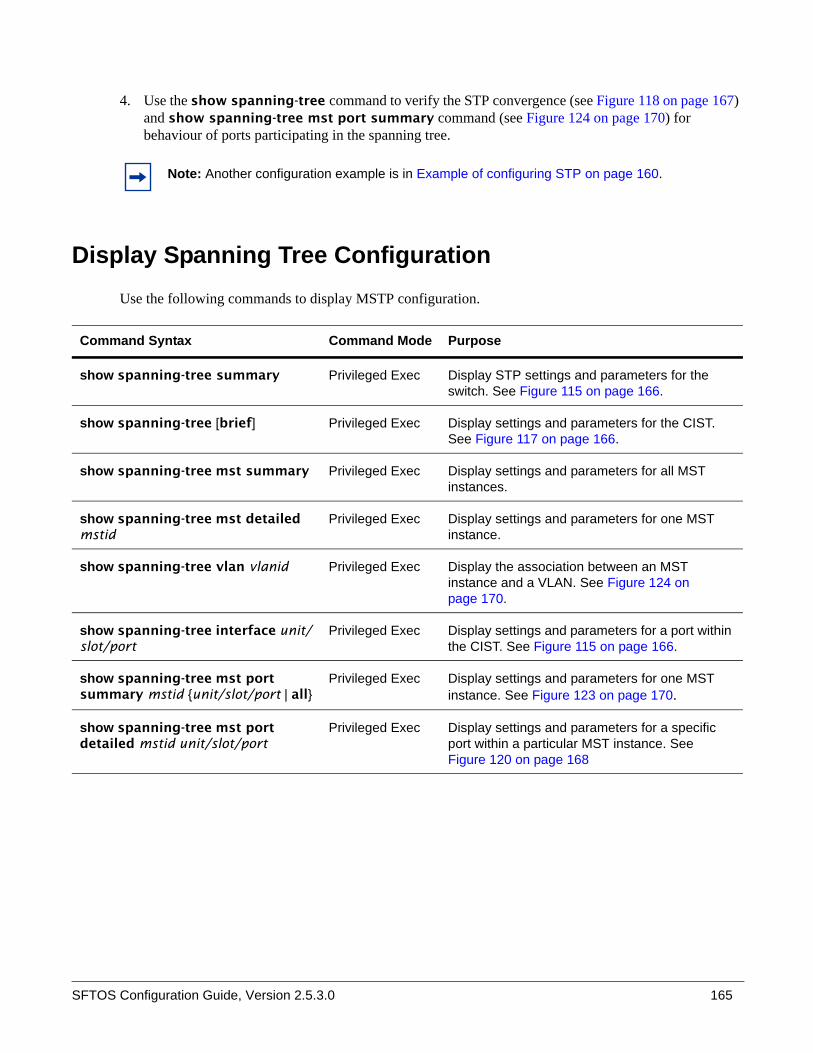
SFTOS Configuration Guide, Version 2.5.3.0 165
4. Use the show spanning-tree command to verify the STP convergence (see Figure 118 on page 167) and show spanning-tree mst port summary command (see Figure 124 on page 170) for behaviour of ports participating in the spanning tree.
Display Spanning Tree ConfigurationUse the following commands to display MSTP configuration.
Note: Another configuration example is in Example of configuring STP on page 160.
Command Syntax Command Mode Purpose
show spanning-tree summary Privileged Exec Display STP settings and parameters for the switch. See Figure 115 on page 166.
show spanning-tree [brief] Privileged Exec Display settings and parameters for the CIST. See Figure 117 on page 166.
show spanning-tree mst summary Privileged Exec Display settings and parameters for all MST instances.
show spanning-tree mst detailed mstid
Privileged Exec Display settings and parameters for one MST instance.
show spanning-tree vlan vlanid Privileged Exec Display the association between an MST instance and a VLAN. See Figure 124 on page 170.
show spanning-tree interface unit/slot/port
Privileged Exec Display settings and parameters for a port within the CIST. See Figure 115 on page 166.
show spanning-tree mst port summary mstid {unit/slot/port | all}
Privileged Exec Display settings and parameters for one MST instance. See Figure 123 on page 170.
show spanning-tree mst port detailed mstid unit/slot/port
Privileged Exec Display settings and parameters for a specific port within a particular MST instance. See Figure 120 on page 168

166
Use the show spanning-tree interface command (Figure 115) and show spanning-tree summary command (Figure 116) to verify that STP is initially disabled, both on interfaces and globally:
Figure 115 Example Output from show spanning-tree interface Command
Figure 116 Example Output from show spanning-tree summary Command
Use the show spanning-tree brief command (Figure 117) to determine current bridge characteristics:
Figure 117 Example Output from spanning-tree brief Command
Force10 #show spanning-tree interface 1/0/1Hello Time..................................... 0Port Mode...................................... EnabledPort Up Time Since Counters Last Cleared....... 0 day 4 hr 50 min 17 secSTP BPDUs Transmitted.......................... 0STP BPDUs Received............................. 0RSTP BPDUs Transmitted......................... 0RSTP BPDUs Received............................ 0MSTP BPDUs Transmitted......................... 0MSTP BPDUs Received............................ 0
Force10 #show spanning-tree summary Spanning Tree Adminmode........... EnabledSpanning Tree Version............. IEEE 802.1sConfiguration Name................ 00-01-E8-D5-A7-82Configuration Revision Level...... 0Configuration Digest Key.......... 0xac36177f50283cd4b83821d8ab26de62Configuration Format Selector..... 0No MST instances to display.
Force10 #show spanning-tree brief
Bridge Priority................................ 32768Bridge Identifier.............................. 80:00:00:01:E8:D5:A7:82Bridge Max Age................................. 20Bridge Max Hops................................ 20Bridge Hello Time.............................. 2Bridge Forward Delay........................... 15Bridge Hold Time............................... 3
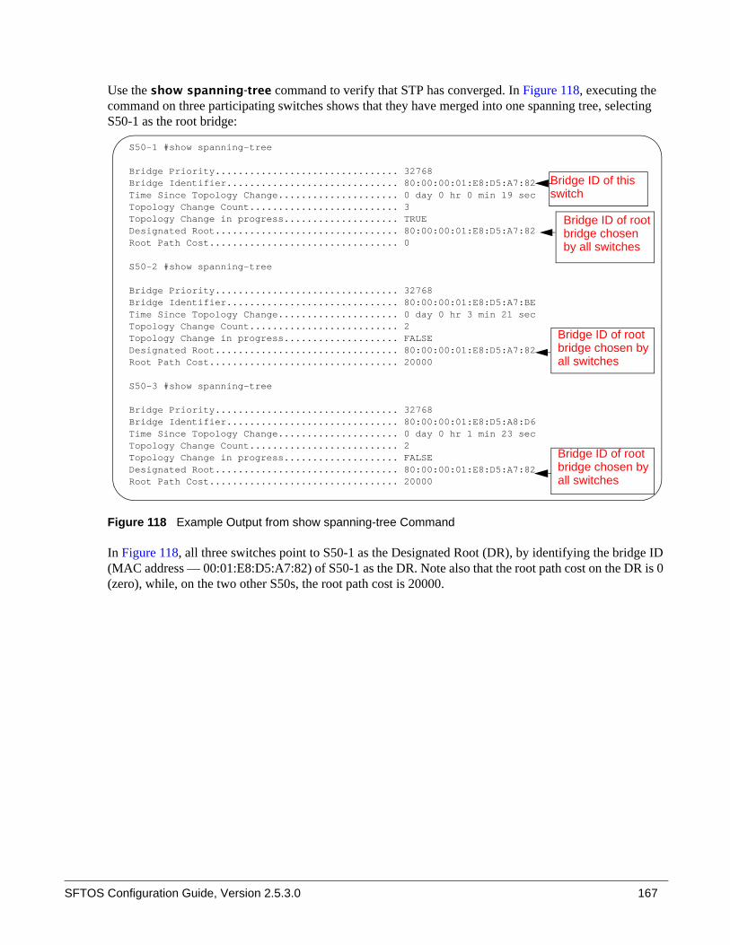
SFTOS Configuration Guide, Version 2.5.3.0 167
Use the show spanning-tree command to verify that STP has converged. In Figure 118, executing the command on three participating switches shows that they have merged into one spanning tree, selecting S50-1 as the root bridge:
Figure 118 Example Output from show spanning-tree Command
In Figure 118, all three switches point to S50-1 as the Designated Root (DR), by identifying the bridge ID (MAC address — 00:01:E8:D5:A7:82) of S50-1 as the DR. Note also that the root path cost on the DR is 0 (zero), while, on the two other S50s, the root path cost is 20000.
S50-1 #show spanning-tree
Bridge Priority................................ 32768Bridge Identifier.............................. 80:00:00:01:E8:D5:A7:82Time Since Topology Change..................... 0 day 0 hr 0 min 19 secTopology Change Count.......................... 3Topology Change in progress.................... TRUEDesignated Root................................ 80:00:00:01:E8:D5:A7:82Root Path Cost................................. 0
S50-2 #show spanning-tree
Bridge Priority................................ 32768Bridge Identifier.............................. 80:00:00:01:E8:D5:A7:BETime Since Topology Change..................... 0 day 0 hr 3 min 21 secTopology Change Count.......................... 2Topology Change in progress.................... FALSEDesignated Root................................ 80:00:00:01:E8:D5:A7:82Root Path Cost................................. 20000
S50-3 #show spanning-tree
Bridge Priority................................ 32768Bridge Identifier.............................. 80:00:00:01:E8:D5:A8:D6Time Since Topology Change..................... 0 day 0 hr 1 min 23 secTopology Change Count.......................... 2Topology Change in progress.................... FALSEDesignated Root................................ 80:00:00:01:E8:D5:A7:82Root Path Cost................................. 20000
Bridge ID of this
switch
Bridge ID of rootbridge chosenby all switches
Bridge ID of rootbridge chosen byall switches
Bridge ID of rootbridge chosen byall switches
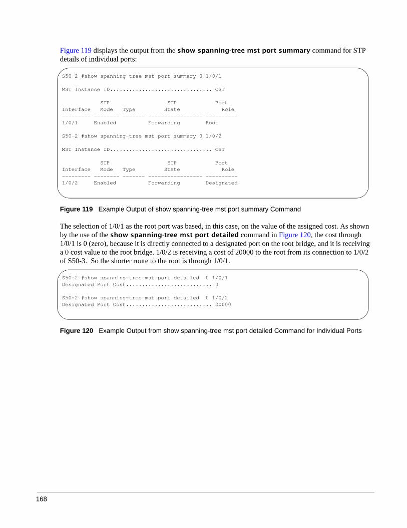
168
Figure 119 displays the output from the show spanning-tree mst port summary command for STP details of individual ports:
Figure 119 Example Output of show spanning-tree mst port summary Command
The selection of 1/0/1 as the root port was based, in this case, on the value of the assigned cost. As shown by the use of the show spanning-tree mst port detailed command in Figure 120, the cost through 1/0/1 is 0 (zero), because it is directly connected to a designated port on the root bridge, and it is receiving a 0 cost value to the root bridge. 1/0/2 is receiving a cost of 20000 to the root from its connection to 1/0/2 of S50-3. So the shorter route to the root is through 1/0/1.
Figure 120 Example Output from show spanning-tree mst port detailed Command for Individual Ports
S50-2 #show spanning-tree mst port summary 0 1/0/1
MST Instance ID................................ CST
STP STP Port Interface Mode Type State Role --------- -------- ------- ----------------- ----------1/0/1 Enabled Forwarding Root
S50-2 #show spanning-tree mst port summary 0 1/0/2
MST Instance ID................................ CST
STP STP Port Interface Mode Type State Role --------- -------- ------- ----------------- ----------1/0/2 Enabled Forwarding Designated
S50-2 #show spanning-tree mst port detailed 0 1/0/1Designated Port Cost........................... 0
S50-2 #show spanning-tree mst port detailed 0 1/0/2Designated Port Cost........................... 20000

SFTOS Configuration Guide, Version 2.5.3.0 169
Figure 121 shows the output of the show spanning-tree mst port summary command from S50-3 for participating ports:
Figure 121 Example Output from show spanning-tree mst port summary Command
In this case (Figure 121), S50-3 has a higher bridge ID than S50-2 and S50-3, so interface 1/0/2 is in the Discarding state, and the physical loop through that port to S50-1 (Figure 124) is broken.
Figure 121 shows the output of the show spanning-tree mst port summary command before lowering the priority of an MST instance. After lowering the priority of the MST instance, see Figure 122:
Figure 122 Example Output from show spanning-tree mst port summary Command
S50-3 #show spanning-tree mst port summary 0 1/0/1
MST Instance ID................................ CST
STP STP Port Interface Mode Type State Role --------- -------- ------- ----------------- ----------1/0/1 Enabled Forwarding Root
S50-3 #show spanning-tree mst port summary 0 1/0/2
MST Instance ID................................ CST
STP STP Port Interface Mode Type State Role --------- -------- ------- ----------------- ----------1/0/2 Enabled Discarding Alternate
Force10 #show spanning-tree mst port summary 50 all
STP STP PortInterface Mode Type State Role--------- -------- ------- ----------------- ----------0/1 Enabled Disabled Disabled0/2 Enabled Disabled Disabled0/3 Enabled Disabled Disabled0/4 Enabled Disabled Disabled0/5 Enabled Disabled Disabled0/6 Enabled Disabled Disabled0/7 Enabled Disabled Disabled0/8 Enabled Disabled Disabled0/9 Enabled Disabled Disabled0/10 Enabled Forwarding Designated0/11 Enabled Discarding Backup0/12 Enabled Disabled Disabled0/13 Enabled Disabled Disabled0/14 Enabled Disabled Disabled0/15 Enabled Disabled Disabled--More-- or (q)uit
Port 10 is the forwarding port.

170
Figure 123 shows the output of the show spanning-tree mst port summary command after lowering the priority of the MST instance (contrast to Figure 121):
Figure 123 Example Output from show spanning-tree mst port summary Command
The show spanning-tree vlan command displays the association of VLANs with MST instances:
Figure 124 Example Output from show spanning-tree vlan Command
Force10 #show spanning-tree mst port summary 50 all
STP STP PortInterface Mode Type State Role--------- -------- ------- ----------------- ----------0/1 Enabled Disabled Disabled0/2 Enabled Disabled Disabled0/3 Enabled Disabled Disabled0/4 Enabled Disabled Disabled0/5 Enabled Disabled Disabled0/6 Enabled Disabled Disabled0/7 Enabled Disabled Disabled0/8 Enabled Disabled Disabled0/9 Enabled Disabled Disabled0/10 Enabled Discarding Backup0/11 Enabled Forwarding Designated0/12 Enabled Disabled Disabled0/13 Enabled Disabled Disabled0/14 Enabled Disabled Disabled0/15 Enabled Disabled Disabled--More-- or (q)uit
After lowering the priority of port 10,port 11 is set as the forwarding port.
s50-5 #show spanning-tree summary
Spanning Tree Adminmode........... EnabledSpanning Tree Version............. IEEE 802.1sConfiguration Name................ spt1Configuration Revision Level...... 1Configuration Digest Key.......... 0x8a9442199657ea49d1124ea768b5d9a2Configuration Format Selector..... 0MST Instances..................... 2,3
s50-5 #show spanning-tree vlan ?
<1-3965> Enter a VLAN identifier.
s50-5 #show spanning-tree vlan 2
VLAN Identifier................................ 2Associated MST Instance........................ 2
s50-5 #show spanning-tree vlan 3
VLAN Identifier................................ 3Associated MST Instance........................ 3

SFTOS Configuration Guide, Version 2.5.3.0 171
Displaying STP, MSTP, and RSTP Operation
Use the show interface ethernet unit/slot/port command to display STP, MSTP, and RSTP BPDUs transmitted and received.
Figure 125 Example Output from show interface ethernet Command
Force10 #show interface ethernet 1/0/1Type........................................... NormalAdmin Mode..................................... Disable Physical Mode.................................. Auto Physical Status................................ Down Speed.......................................... 0 - None Duplex......................................... N/A Link Status.................................... Down MAC Address.................................... 0001.E8D5.BBDENative Vlan.................................... 1
!---------------<snip>-----------------!
802.3x Pause Frames Transmitted................ 0 GVRP PDUs received............................. 0 GVRP PDUs Transmitted.......................... 0 GVRP Failed Registrations...................... 0 GMRP PDUs Received............................. 0 GMRP PDUs Transmitted.......................... 0 GMRP Failed Registrations...................... 0
STP BPDUs Transmitted.......................... 0STP BPDUs Received............................. 0RSTP BPDUs Transmitted......................... 0RSTP BPDUs Received............................ 0MSTP BPDUs Transmitted......................... 0MSTP BPDUs Received............................ 0
EAPOL Frames Transmitted....................... 0EAPOL Start Frames Received.................... 0
Time Since Counters Last Cleared............... 0 day 0 hr 11 min 10 sec

172

SFTOS Configuration Guide, Version 2.5.3.0 173
This chapter contains the following major sections:
• Link Aggregation—IEEE 802.3• Link Aggregation Group (LAG) Commands on page 176• Configuring a LAG on page 178• Link Aggregation Control Protocol (LACP) on page 182• Displaying LAGs (Port Channels) on page 184
Link Aggregation—IEEE 802.3A Link Aggregation Group (LAG), also called a Port Channel or port trunking, conforms to IEEE 802.3 (802.3ad), enabling MAC interfaces to be grouped logically to appear as one physical link. A LAG enables you to treat multiple physical links between two end-points as a single logical link, providing automatic redundancy between two devices. A LAG is often used to directly connect two switches when the traffic between them requires high bandwidth and reliability, or to provide a higher bandwidth connection to a public network.
You can configure LAGs as either dynamic or static (SFTOS configures dynamic LAGs by default.):
• Dynamic configuration uses the IEEE 802.3ad standard, which provides for the periodic exchanges of LACP PDUs (Link Aggregation Control Protocol Protocol Data Units).
• Static configuration is used when connecting the switch to an external switch that does not support the exchange of LACP PDUs.
Chapter 10 Link Aggregation
Note: SFTOS 2.5.1 introduces the Interface Port Channel Config mode (see Interface Port Channel Config mode commands on page 177), which contains new commands and some commands that are versions of previous commands used for configuring Port Channels, generically called Link Aggregation Groups (LAGs). Some of the previous commands are deprecated, while some remain, providing alternative ways to accomplish a task.
Starting with SFTOS 2.5.1, static LAGs and dynamic LAGs — through Link Aggregation Control Protocol (LACP) — can coexist in the same configuration. Up to 48 LAGs can be configured in a stack, up to six of them dynamic LAGs.
SFTOS 2.5.1 discontinues the logical interface identifier (0/1/xx) for a LAG (Port Channel). Instead, the ID is an integer, as exemplified in Figure 130 on page 181.
Configuration migration: Range values of some commands used to configure your system with SFTOS versions previous to SFTOS 2.5.1 might need to be adjusted to the range values in SFTOS 2.5.1 and above.

174
A LAG can offer the following benefits:
• Increased reliability and availability — if one of the physical links in the LAG goes down, traffic will be dynamically and transparently reassigned to one of the other physical links.
• Better use of physical resources — traffic can be load-balanced across the physical links.• Increased bandwidth — the aggregated physical links deliver higher bandwidth than each individual
link. • Incremental increase in bandwidth — A LAG may be used when a physical upgrade would produce a
10-times increase in bandwidth, but only a two- or five-times increase is required.
LAGs:
• Behave like any other Ethernet link to a VLAN• Are treated as physical ports with the same configuration parameters, spanning tree port priority, path
cost, etc.• Can be a member of a VLAN: See VLANs on page 215. However, LAGs cannot be a member of the
Default VLAN, VLAN 1.• Can have a router port member, but routing will be disabled while it is a member. For information on
LAG routing, see Link Aggregation on page 277 in the Routing chapter. • Can be comprised of interfaces from different units of an S-Series stack.
LAG Load Distribution
Traffic is distributed (load-balanced) over links in a LAG using a hashing algorithm. Since the packet-forwarding ASICs differ among the S-Series platforms, the load-balancing algorithm is also different. Currently, the CLI does not include a command to change the algorithm.
• S50: IPv4 packets: The hash is based on the eXclusive OR (XOR) of the 3 least significant bits (LSB) of the source and destination IP addresses.Non-IP packets: The hash is based on the XOR of the 3 LSBs of the source and destination MAC addresses.
• S50V, S50N, S25P: IPv4 and IPv6 packets: The hash is based on the XOR of the source IP (v4 or v6) address and Layer 4 port with the destination IP (v4 or v6) address and Layer 4 port.Non-IP packets: The hash is based on the source and destination MAC addresses, VLAN, type, ingress ASIC, and ingress port.
• S2410: All packets: The hash is based on the source and destination MAC addresses, type, VLAN, VLAN priority, and ingress port..
On all platforms, MAC addresses must be learned for hashing to work. Broadcast, unknown unicast, and multicast packets are sent to a single port (the lowest numbered port) in the LAG.

SFTOS Configuration Guide, Version 2.5.3.0 175
LAG Implementation Restrictions
Interface restrictions:
• All of the physical links of a LAG must run in full-duplex mode at the same speed. Set the speed and mode of a port to that of the LAG before adding the port to the LAG.
• LAG speed may not be changed.• Routing is not supported on links in a LAG.• An interface can belong to only one LAG.• SFTOS supports 48 LAGs, with a maximum of eight members each.
SFTOS supports IEEE 802.3 Clause 43 with minor exceptions:
• No optional features supported, e.g. Marker Generator/Receiver• MUX machine implemented as coupled, not independent control• Some MIB variables are not supported.
Link Aggregation—MIB Support
The IEEE 802.3 Annex 30c MIB objects that are not supported are:
• dot3adAggPortDebugTable• dot3adAggPortStatsMarkerResponsePDUsRx• dot3adAggPortStatsMarkerPDUsTx• dot3adAggPortActorAdminSystemPriority• dot3adAggPortActorOperSystemPriority• dot3adAggPortPartnerAdminSystemPriority• dot3adAggPortPartnerOperSystemPriority• dot3adTablesLastChanged
Static LAG Requirements
Manual aggregation is disabled by default, and when enabled, applies to all LAG interfaces. Manual aggregation uses the following default values:
• If an LACP PDU (Link Aggregation Control Protocol Protocol Data Unit) is received with different values, the link will drop out.
• When all member links have dropped out, the group will re-aggregate with the new information.
If the partner does not respond with LACP PDUs, the system will wait three seconds and aggregate manually.
The static LAG configuration should only be enabled if both parties are 802.3ad-compliant and have the protocol enabled.
LAGs should be configured and STP-enabled on both devices before connecting cables.

176
Link Aggregation Group (LAG) Commands
Privileged Exec and User Exec mode commands• To remove all LAGs:
— clear port-channel
• To display a summary of LAGs, including port assignments:— show interface port-channel brief
• To display settings and counters for a specific LAG, including port assignments:— show interface port-channel 1–128
Global Config mode commands
The CLI commands in the Global Config mode used to configure LAGs are:
• To create the Port Channel (LAG) and invoke the Interface Port Channel Config mode:— [no] interface port-channel 1-128 (If the Port Channel is already created, this command
simply invokes the Interface Port Channel Config mode.)• To configure the LAG name:
— In SFTOS 2.5.1, there is not a direct replacement for the deprecated port-channel name command. Use the interface port-channel command to identify the Port Channel by an integer ID, and use the description line command to add a description for the selected Port Channel. For more, see Interface Port Channel Config mode commands, below.
• Enable link trap notifications for all Port Channels (LAGs):— [no] port-channel linktrap all
— (or, at the LAG prompt: snmp trap link-status) • To [disable] enable the administrative mode for all LAGs:
— [no] port-channel enable all
• To delete one or more ports from a LAG:— In SFTOS 2.5.1, the no channel-member unit/slot/port-unit/slot/port command replaces
deleteport unit/slot/port | all
• To delete a specific LAG:— In SFTOS 2.5.1, the no interface port-channel 1-128 command replaces no port-channel
unit/slot/port
• To delete all LAGs (see clear port-channel in Privileged Exec mode)
Note: The [no] port lacpmode enable all command is deprecated.

SFTOS Configuration Guide, Version 2.5.3.0 177
Interface Port Channel Config mode commandsThe Interface Port Channel Config mode was introduced in SFTOS version 2.5.1. The [no] interface port-channel 1–128 command, used from the Global Config mode, accesses the mode. The command first creates a new LAG with an ID you assign (an integer between 1 and 128), or, if the number you enter is already assigned to a LAG, then the command invokes the mode for that LAG.
The CLI commands in the Interface Port Channel Config mode include the following:• Add to the selected LAG (or delete from it), one or more ports:
— [no] channel-member unit/slot/port–unit/slot/port,unit/slot/port
• Enter a description for the selected LAG:— [no] description
• Configure the priority for untagged frames:— dot1p-priority 0-7
• Set the maximum transmission unit (MTU) size (in bytes) for the selected LAG:— [no] mtu 1518-9216
• Attach a specified ACL to the selected LAG (and, optionally, to also enter a sequence number (from 1-4294967295) that indicates the order of this ACL relative to other ACLs assigned to this LAG):— ip access-group 1–199 [1-4294967295] in
• Attach a MAC ACL identified by name to the selected LAG in the ingress direction. The 1-4294967295 option is as described above:— mac access-group name [1-4294967295]
• Enable the support of static link aggregations on the LAG. By default, the static capability for all LAGs is disabled:— protocol static
• Reenable the LACP on the selected LAG:— protocol lacp
• Enable or disable the LAG:— [no] shutdown
• Enable or disable link status traps for the LAG:— [no] snmp trap link-status
• Set the spanning-tree operational mode on the selected LAG:— [no] spanning-tree
• Set or clear the CST cost for the LAG:— [no] spanning tree 0 cost 1-65535
• Set or clear the CST priority for the LAG.— [no] spanning tree 0 priority 0-15
• Associate or disassociate a multiple spanning tree instance with cost to the LAG:— [no] spanning-tree MSTi 0-63 cost 1-2000000
• Set or clear the priority associated with the multiple spanning tree instance for the LAG.— [no] spanning-tree MSTi 0-63 priority 0-240
• Enable or disable spanning-tree MSTP edge-port mode:— [no] spanning-tree mstp edge-port

178
Interface Config mode commands
The CLI commands in Interface Config mode used to configure LAGs are:
• Add a port to a LAG:— addport unit/slot/port (where unit/slot/port is the logical interface defined by the system for
the LAG)• Delete ports:
— deleteport unit/slot/port
• Delete one or all LAGs:— delete interface {unit/slot/port | all}
• Set spanning-tree options on a selected LAG:— spanning-tree {edgeport | hello-time | port | mst} (Specify edgeport for fast, no
spanning-tree edgeport for 802.1d.)
Static LAG CLI ManagementSFTOS configures dynamic LAGs by default. If you want to convert the LAG to a static LAG, use:
• protocol static, in Interface Port Channel Config mode. (Before v. 2.5.1, the syntax was port-channel staticcapability.)— All LAGs with configured members but no active members will now aggregate statically on link
UP interfaces.• show interface port-channel brief (Privileged Exec mode and User Exec mode) displays whether
static capability is enabled.
Configuring a LAG
The following procedure shows the basic steps for creating and configuring a LAG (Port Channel).
Note: The [no] port lacpmode enable command is deprecated.
Note: By default, dynamic LAGs are created, and link trap notification is enabled.Note: A LAG (Port Channel) cannot have an IP address.
Step Command Syntax Command Mode Purpose
1 show interface port-channel brief
Privileged Exec Display current settings. Note currently configured LAGs. (Before v. 2.5.1, the syntax was show port-channel all.)
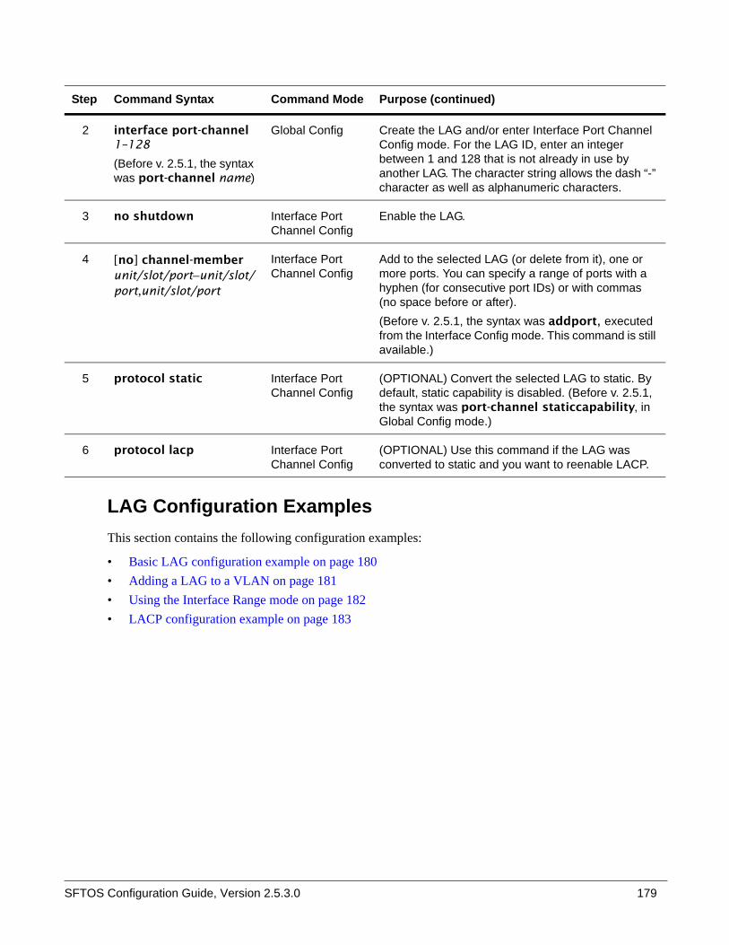
SFTOS Configuration Guide, Version 2.5.3.0 179
LAG Configuration ExamplesThis section contains the following configuration examples:
• Basic LAG configuration example on page 180• Adding a LAG to a VLAN on page 181• Using the Interface Range mode on page 182• LACP configuration example on page 183
2 interface port-channel 1–128
(Before v. 2.5.1, the syntax was port-channel name)
Global Config Create the LAG and/or enter Interface Port Channel Config mode. For the LAG ID, enter an integer between 1 and 128 that is not already in use by another LAG. The character string allows the dash “-” character as well as alphanumeric characters.
3 no shutdown Interface Port Channel Config
Enable the LAG.
4 [no] channel-member unit/slot/port–unit/slot/port,unit/slot/port
Interface Port Channel Config
Add to the selected LAG (or delete from it), one or more ports. You can specify a range of ports with a hyphen (for consecutive port IDs) or with commas (no space before or after).(Before v. 2.5.1, the syntax was addport, executed from the Interface Config mode. This command is still available.)
5 protocol static Interface Port Channel Config
(OPTIONAL) Convert the selected LAG to static. By default, static capability is disabled. (Before v. 2.5.1, the syntax was port-channel staticcapability, in Global Config mode.)
6 protocol lacp Interface Port Channel Config
(OPTIONAL) Use this command if the LAG was converted to static and you want to reenable LACP.
Step Command Syntax Command Mode Purpose (continued)

180
Basic LAG configuration example
This example shows configuring the S-Series switch to support LAGs to a server and to a Layer 2 switch.
Figure 126 LAG Example Network Diagram
1. Use the show interface port-channel brief command to learn the LAG IDs already in use (see Figure 129 on page 181). This example assumes that IDs 10 and 20 are available.
2. Create LAG 10.
Figure 127 Creating LAG 10
Subnet3
Port 0/8LAG_20
Layer 2 Switch
Port 0/9LAG_20
Server
Port 0/2LAG_10
Port 0/3LAG_10
Layer 3 Switch
Subnet 3Subnet 2
Force10 #configForce10 (Config)#interface port-channel 10Force10 (conf-if-po-10)#no shutdownForce10 (conf-if-po-10)#channel-member 1/0/2-1/0/3Force10 (conf-if-po-10)#protocol static <============Force10 (conf-if-po-10)#exit
required command if you want to create a static LAG
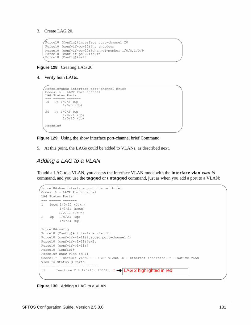
SFTOS Configuration Guide, Version 2.5.3.0 181
3. Create LAG 20.
Figure 128 Creating LAG 20
4. Verify both LAGs.
Figure 129 Using the show interface port-channel brief Command
5. At this point, the LAGs could be added to VLANs, as described next.
Adding a LAG to a VLAN
To add a LAG to a VLAN, you access the Interface VLAN mode with the interface vlan vlan-id command, and you use the tagged or untagged command, just as when you add a port to a VLAN:
Figure 130 Adding a LAG to a VLAN
Force10 (Config)#interface port-channel 20Force10 (conf-if-po-10)#no shutdownForce10 (conf-if-po-20)#channel-member 1/0/8,1/0/9Force10 (conf-if-po-20)#exitForce10 (Config)#exit
Force10#show interface port-channel briefCodes: L - LACP Port-channelLAG Status Ports--- ------ -------10 Up 1/0/2 (Up)
1/0/3 (Up)
20 Up 1/0/2 (Up)1/0/24 (Up)1/0/25 (Up)
Force10#
Force10#show interface port-channel briefCodes: L - LACP Port-channelLAG Status Ports--- ------ -------1 Down 1/0/20 (Down)
1/0/21 (Down)1/0/22 (Down)
2 Up 1/0/23 (Up)1/0/24 (Up)
Force10#configForce10 (Config)# interface vlan 11Force10 (conf-if-vl-11)#tagged port-channel 2Force10 (conf-if-vl-11)#exitForce10 (conf-if-vl-11)#Force10 (Config)#Force10# show vlan id 11Codes: * - Default VLAN, G - GVRP VLANs, E - Ethernet interface, ^ - Native VLANVlan Id Status Q Ports--------- ---------- - ------11 Inactive T E 1/0/10, 1/0/11, 2 LAG 2 highlighted in red

182
Using the Interface Range mode
If you are applying the same configuration elements to a number of LAGs (also called bulk configuration), you can replicate the steps shown in the examples above for all of those LAGs from the Interface Range mode. The System Configuration chapter in the SFTOS Command Reference provides details on the command syntax used for the interface range command to define the range and access the mode.
The command families available from the Port Channel Range prompt within that mode are displayed here.
Figure 131 Commands Available in Interface Range Mode for LAGs
Link Aggregation Control Protocol (LACP)The Link Aggregation Control Protocol (LACP) provides a standardized means of exchanging information between two systems (also called partner systems) and dynamically establishing LAGs between the two partner systems.
LACP allows the exchange of messages on a link to allow their Link Aggregation Control instances to reach agreement on the identity of the LAG to which the link belongs, move the link to that LAG, and enable the transmission and reception functions in an orderly manner.
SFTOS configures dynamic LAGs by default, using LACP. The SFTOS implementation of LACP is based on the standards specified in the IEEE 802.3: “Carrier sense multiple access with collision detection (CSMA/CD) access method and physical layer specifications.”
Note: You can approximate LAG bulk configuration when you assign a group of ports to a LAG with one channel-member command (Interface Port Channel Config mode). For example, channel-member 1/0/10-1/0/14.
Force10 (Config)#interface range port-channel 1,3Force10 (conf-if-range-po-1,3)#?classofservice Configure Class of Service parameters.cos-queue Configure the Cos Queue Parameters.description Add Description to the interfacedot1p-priority Configure the priority for untagged frames.exit To exit from the mode.gmrp Set GARP Multicast Registration Protocol parameters.gvrp Set GARP VLAN Registration Protocol parameters.igmp Enable/Disable IGMP Snooping on a selected interfaceip Configure IP parameters.mac Configure MAC Access List group parameters.mode Configure the double VLAN tunnel mode for this interface.mtu Sets the default MTU size.port-security Enable/Disable Port MAC Locking/Security for interface.protocol Configure protocol type for port-channel.rate-interval Sets the traffic monitoring rate intervalservice-policy Configure DiffServ Service.set Configure switch options and settings.shutdown Enable/Disable a port.snmp Configure SNMP options.snmp-server Enable/Disable SNMP violation traps interface.spanning-tree Set the spanning tree operational mode.vlan Configure VLAN parameters.

SFTOS Configuration Guide, Version 2.5.3.0 183
LACP works by constantly exchanging custom MAC PDUs across LAN Ethernet links. The protocol packets are only exchanged between ports that are configured to be LACP-capable.
LACP Configuration
SFTOS allows the user to enable LACP and configure LACP timeout characteristics for a particular LAG.
The following commands configure LACP:
LACP configuration example
Figure 132 shows the assignment of ports to a LAG. Figure 133 displays that the LAG is dynamic (enabled with LACP) by default:
Figure 132 Example of LAG Configuration with LACP Enabled by Default
You would also need to enable the ports in the LAG.
To convert the LAG to static, use protocol static, in Interface Port Channel Config mode.
Note: LACP is enabled by default.
Command Syntax Command Mode Purpose
protocol lacp Interface Port Channel Config
If you converted a LAG to static, this command reenables LACP on the LAG.
[no] port lacptimeout {short all | long all}
Global Config Configure the system LACP timeout.
[no] port lacptimeout {short | long} Interface Config Configure the LACP timeout at a port level.
Note: The [no] port lacpmode enable command (Interface Config mode) and [no] port lacpmode enable all command (Global Config mode) are deprecated.
Force10 (Config)#interface port-channel 2Force10 (conf-if-po- 2)#no shutdownForce10 (conf-if-po- 2)#channel-member 1/0/22-1/0/24Force10 (conf-if-po- 2)#exit

184
Verify the status of the LAG as dynamic created through LACP:
Figure 133 Displaying Details on a LAG with the show interface port-channel Command
Displaying LAGs (Port Channels)In SFTOS v. 2.5.1, the show port-channel all command is replaced by the show interface port-channel command. An example of the show interface port-channel 1-128 option is shown in Figure 133, above. The show interface port-channel brief version is shown in Figure 134.
Figure 134 Displaying LAGs with the show interfaces port-channel brief Command
Force10 (Config)#exitForce10#show interface port-channel 2
Description.................................... MAC Address.................................... 00:01:E8:D5:A0:81MTU............................................ 1518
Packets RX and TX 64 Octets.................... 0Packets RX and TX 65-127 Octets................ 0Packets RX and TX 128-255 Octets............... 0Packets RX and TX 256-511 Octets............... 0Packets RX and TX 512-1023 Octets.............. 0Packets RX and TX 1024-1518 Octets............. 0Packets RX and TX 1519-1522 Octets............. 0Packets RX and TX 1523-2047 Octets............. 0Packets RX and TX 2048-4095 Octets............. 0Packets RX and TX 4096-9216 Octets............. 0
Jabbers Received............................... 0Fragments Received............................. 0Undersize Received............................. 0Alignment Errors............................... 0FCS Errors..................................... 0Overruns....................................... 0Unicast Packets Received....................... 0--More-- or (q)uitMulticast Packets Received..................... 0Broadcast Packets Received..................... 0Single Collision Frames........................ 0Multiple Collision Frames...................... 0Excessive Collision Frames..................... 0Port Membership Discards....................... 0
Time Since Counters Last Cleared............... 0 day 0 hr 46 min 38 sec Link Adm. Trap STP Mbr Port PortLAG Link Mode Mode Mode Type Ports Speed Active--- ------ ---- ---- ------ ------- ------ -------- ------1 Down En. En. Dis. Dynamic 1/0/22 Auto False 1/0/23 Auto False 1/0/24 Auto False
Force10#show interface port-channel brief
Codes: L - LACP Port-channel
LAG Status Ports--- ------ -------1 Up 1/0/3 (Up) 1/0/4 (Up) 1/0/5 (Up) 1/0/6 (Up)2 Down 1/0/11 (Down) 1/0/12 (Down) 1/0/13 (Down) 1/0/14 (Down)
SFTOS Configuration Guide, Version 2.5.3.0 185
This chapter contains the following major sections:
• Using Differentiated Services (DiffServ) on page 185• Deploying DiffServ on page 188• Monitoring DiffServ on page 192• Configuring Differentiated Services by Department on page 199• Configuring Differentiated Services for Voice over IP on page 202
Using Differentiated Services (DiffServ)This section contains the following subsections:
• Deploying DiffServ on page 188• Monitoring DiffServ on page 192• Configuring Differentiated Services by Department on page 199• Configuring Differentiated Services for Voice over IP on page 202
For syntax details on commands discussed in this chapter, see Chapter 19 (Quality of Service (QoS) Commands) in the SFTOS Command Reference. That chapter also provides syntax statements for Class of Service commands (CoS). See also, in this chapter, Using Differentiated Services (DiffServ) on page 185, for more information on controlling traffic.
Differentiated Services (DiffServ) is one technique for implementing Quality of Service (QoS) policies. Using DiffServ in your network allows you to directly configure the relevant parameters on the switches and routers rather than using a resource reservation protocol.This section explains how to configure the S-Series to identify which traffic class a packet belongs to and how the packet should be handled to provide the desired quality of service. As implemented on the S-Series, DiffServ allows you to control what traffic is accepted, what traffic is transmitted, and what bandwidth guarantees are provided.
How you configure DiffServ support on the S-Series will likely vary depending on the role of the switch in your network:
Chapter 11 Quality of Service

186
• Edge device: An edge device handles ingress traffic, flowing towards the core of the network, and egress traffic, flowing away from the core. An edge device will segregate inbound traffic into a small set of traffic classes, and is responsible for determining a packet’s classification. Classification will be primarily based on the contents of the Layer 3 and Layer 4 headers, and will be recorded in the Differentiated Services Code Point (DSCP) added to a packet’s IP header.
• Interior node: A switch in the core of the network is responsible for forwarding packets, rather than for classifying them. It will decode the DSCP in an incoming packet, and provide buffering and forwarding services using the appropriate queue management algorithms.
To configure DiffServ on a particular S-Series router, you first determine the QoS (quality of service) requirements for the network as a whole. The requirements are expressed in terms of rules, which are used to classify either inbound or outbound traffic on a particular interface. Rules are defined in terms of classes, policies, and services:• Class: A class consists of a set of rules that identify which packets belong to the class. Inbound traffic
is separated into traffic classes based on Layer 3 and 4 header data and the VLAN ID, and marked with a corresponding DSCP value. Outbound traffic is grouped into forwarding classes based on the DSCP value, and allocated priority and bandwidth accordingly. One type of class is supported:— All: Every match criterion defined for the class must be true for a match to occur.
• Policy: Defines the QoS attributes for one or more traffic classes. An example of an attribute is the specification of minimum or maximum bandwidth in terms of kbps or percent of link capacity. The S-Series supports two policy types:
• Traffic Conditioning Policy: This type of policy is associated with an inbound traffic class and specifies the actions to be performed on packets meeting the class rules:
— Marking the packet with a given DSCP code point— Policing packets by dropping or re-marking those that exceed the assigned data rate of
the class— Counting the traffic within the class
• Service Provisioning Policy: This type of policy is associated with an outbound traffic class and affects how packets are transmitted.
• Service: Assigns a policy to an interface for either inbound or outbound traffic
The user configures Differentiated Services (Diffserv) in the stages described above by specifying:
• Class— Creating and deleting classes— Defining match criteria for a class. Note: The only way to remove an individual match criterion
from an existing class definition is to delete the class and re-create it.• Policy
— Creating and deleting policies— Associating classes with a policy— Defining policy statements for a policy/class combination
• Service— Adding and removing a policy to/from a directional (i.e., inbound, outbound) interface
Note: SFTOS currently supports the inbound direction only.
SFTOS Configuration Guide, Version 2.5.3.0 187
Packets are filtered and processed based on defined criteria. The filtering criteria is defined by a class. The processing is defined by a policy’s attributes. Policy attributes may be defined on a per-class instance basis, and it is these attributes that are applied when a match occurs.
Packet processing begins by testing the match criteria for a packet. A policy is applied to a packet when a class match within that policy is found.
Note that the type of class — all, any, or ACL — has a bearing on the validity of match criteria specified when defining the class. A class type of any processes its match rules in an ordered sequence; additional rules specified for such a class simply extend this list. A class type of acl obtains its rule list by interpreting each ACL rule definition at the time the Diffserv class is created. Differences arise when specifying match criteria for a class type all, since only one value for each non-excluded match field is allowed within a class definition.
The following class restrictions are imposed by the DiffServ design:
• Nested class support limited to:— any within any
— all within all
— No nested not conditions— No nested acl class types— Each class contains at most one referenced class.
• Hierarchical service policies are not supported in a class definition.• Access list matched by reference only, and must be the sole criterion in a class.
— I.e., ACL rules copied as class match criteria at time of class creation, with class type any
— Implicit ACL deny all rule also copied— No nesting of class type acl
Regarding nested classes, referred to here as class references, a given class definition can contain at most one reference to another class, which can be combined with other match criteria. The referenced class is truly a reference and not a copy, since additions to a referenced class affect all classes that reference it. Changes to any class definition currently referenced by any other class must result in valid class definitions for all derived classes otherwise the change is rejected. A class reference may be removed from a class definition.
The user can display summary and detailed information for classes, policies and services. All configuration information is accessible via the CLI and SNMP user interfaces.
This command sets the DiffServ operational mode to active. While disabled, the DiffServ configuration is retained and can be changed, but it is not activated. When enabled, Diffserv services are activated.
Note: If a field is already specified for a class, all subsequent attempts to specify the same field fail, including the cases where a field can be specified multiple ways through alternative formats. The exception to this is when the ‘exclude’ option is specified, in which case this restriction does not apply to the excluded fields.

188
Deploying DiffServThe four basic steps necessary to deploy DiffServ are:
1. Create class-maps. (See Creating Class-maps/DiffServ Classes on page 188.)
A class-map is used to differentiate between types of traffic based on a packet’s match to defined rules in the class-map. For information on using a class-map in configuration scripting, see Using Configuration Scripts on page 31.
2. Create a policy-map. (See Creating a Policy-Map on page 190.)
A policy-map references a class-map and defines the actions to be taken for traffic in a referenced class.
3. Apply the policy to interfaces. (See Applying Policies on page 191.)
Apply the policy to the interfaces in an ingress or egress capacity.
4. Enable DiffServ globally. (See Enabling Differentiated Services on page 192.)
The following command sequence is annotated to show the four stages described above. The example configures a policy of 1MByte rate limiting, with a 128K burst, sets a CoS, and assigns it to a port:
Figure 135 DiffServ Example: Configuring Rate Limiting on a Port
Using "class-map" policy options, you can configure more granular matching based on Layer 2 or Layer 3 headers. Input rate limiting is configured with the police-simple command. Use traffic-shape for egress rate shaping.
Creating Class-maps/DiffServ Classes
The first step in deploying DiffServ is to create a DiffServ class. From the Global Config mode, use the class-map match-all classname command.
The match-all class type indicates that all of the individual match conditions must be true for a packet to be considered a member of the class.
class-map match-all match_allmatch anyexit!Completed Step 1!policy-map rate_limit inclass match_allpolice-simple 1024 128 conform-action set-cos-transmit 7 violate-action dropexit!Completed Step 2!interface 1/0/7service-policy in rate_limitno shutdownexit!Completed Step 3!diffserv!Completed Step 4!

SFTOS Configuration Guide, Version 2.5.3.0 189
The classname parameter is a case-sensitive alphanumeric string from 1 to 31 characters that you create to uniquely identify the class.
For example, entering class-map match-all Dallas means “Create a class named Dallas that must match all statements in the policy.”
After entering the command, and a new classname is defined, this command invokes the Class Map Config mode — “(Config-classmap)#” prompt. Within that mode, you can continue to refine the definition of the class.
After exiting the Class Map Config mode, you can reenter the mode to edit the named class by using the command class-map existing_classname, where existing_classname is the classname that you defined earlier.
The example below creates a class named “cl-map-1”. The map requires that all rules in the list must be matched. If any of the rules are not a match for the traffic, the traffic is not a member of that class. In this case, the traffic must carry a destination IP address in the 10.1.1.0 network and have a destination port of 7:
Figure 136 Using the class-map match-all Command
Note that the example below, looks for packets with an ip-precedence of 1, but also references another class map (cl-map-1):
Figure 137 Using the class-map match-all Command
To delete an existing class, use the command no class-map existing_classname from the Global Config mode. This command may be issued at any time; if the class is currently referenced by one or more policies or by any other class, this deletion attempt shall fail.
Note: The word “default” is reserved and must not be used as a class name.
Note: Class match conditions are obtained from the referenced access list (ACL) at the time of class creation. Thus, any subsequent changes to the referenced ACL definition do not affect the DiffServ class. To pick up the latest ACL definition, delete and recreate the class.
class-map match-all cl-map-1match dstip 10.1.1.0 255.255.255.0match dstl4port 7exit
class-map match-all cm-3match ip precedence 1match class-map cl-map-1exit

190
Creating a Policy-Map
The second step in deploying DiffServ is to create a policy-map. From the Global Config mode, use the policy-map command (Figure 138) to create or identify an existing policy-map. The policy-map defines:
• Traffic Conditioning—Specify traffic conditioning actions (policing, marking, shaping) to apply to traffic classes
• Service Provisioning—Specify bandwidth and queue depth management requirements of service levels — EF (expedited forwarding), AF (assured forwarding), BE (best effort), and CS (class selector). See the explanation of those dscpval parameter options in the match ip dscp command syntax statement in the QoS chapter of the SFTOS Command Reference.
The policy commands associate a traffic class, which was defined by the class command set, with one or more QoS policy attributes. This association is then assigned to an interface to form a service. The user specifies the policy name when the policy is created.
The DiffServ CLI does not necessarily require that users associate only one traffic class to one policy. In fact, multiple traffic classes can be associated with a single policy, each defining a particular treatment for packets that match the class definition. When a packet satisfies the conditions of more than one class, preference is based on the order in which the classes were added to the policy, with the foremost class taking highest precedence.
This set of commands consists of policy creation/deletion, class addition/removal, and individual policy attributes. Note that the only way to remove an individual policy attribute from a class instance within a policy is to remove the class instance and re-add it to the policy. The values associated with an existing policy attribute can be changed without removing the class instance.
The policy-map command establishes a new DiffServ policy. The syntax is policy-map policyname in, where policyname is a case-sensitive alphanumeric string from 1 to 31 characters uniquely identifying the policy. The in keyword indicates that the policy is specific to inbound traffic, because SFTOS supports only the inbound (ingress) direction.
Note: Class instances are always added to the end of an existing policy. While existing class instances may be removed, their previous location in the policy is not reused, so the number of class instance additions/removals is limited. In general, significant changes to a policy definition require that the entire policy be deleted and re-created with the desired configuration.
Note: The policy type dictates which of the individual policy attribute commands are valid within the policy definition.
Note: The CLI mode is changed to Policy-Map when this command is successfully executed.
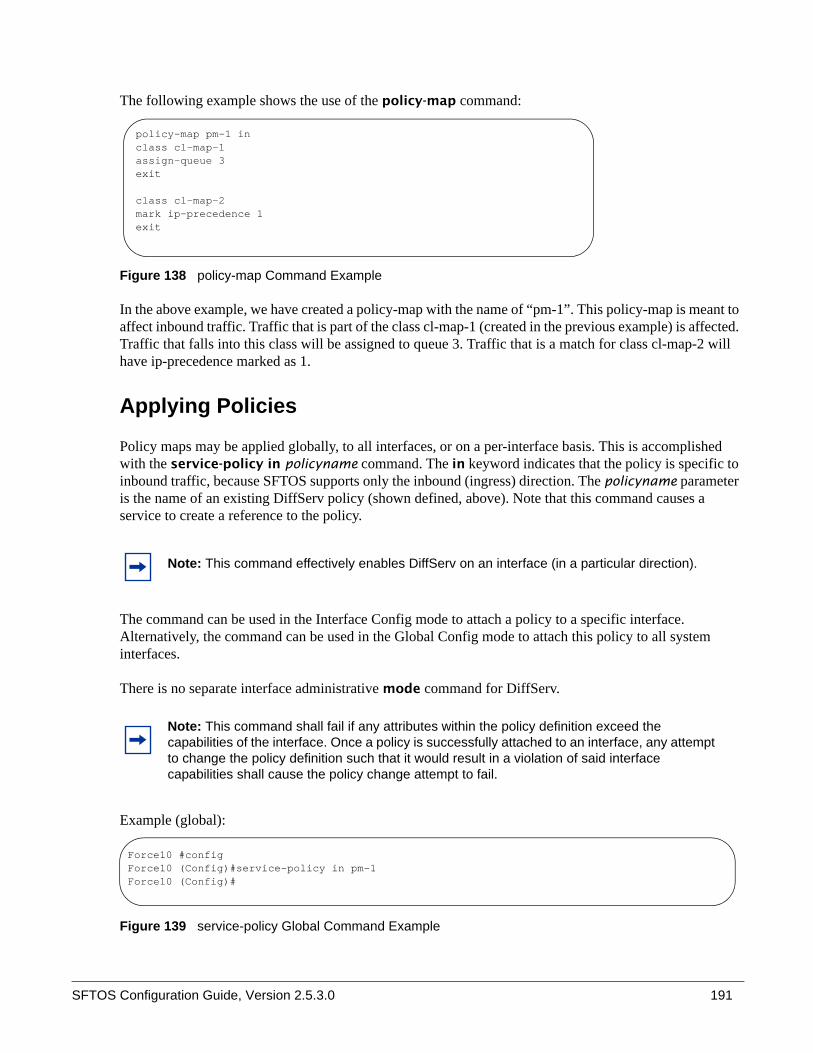
SFTOS Configuration Guide, Version 2.5.3.0 191
The following example shows the use of the policy-map command:
Figure 138 policy-map Command Example
In the above example, we have created a policy-map with the name of “pm-1”. This policy-map is meant to affect inbound traffic. Traffic that is part of the class cl-map-1 (created in the previous example) is affected. Traffic that falls into this class will be assigned to queue 3. Traffic that is a match for class cl-map-2 will have ip-precedence marked as 1.
Applying Policies
Policy maps may be applied globally, to all interfaces, or on a per-interface basis. This is accomplished with the service-policy in policyname command. The in keyword indicates that the policy is specific to inbound traffic, because SFTOS supports only the inbound (ingress) direction. The policyname parameter is the name of an existing DiffServ policy (shown defined, above). Note that this command causes a service to create a reference to the policy.
The command can be used in the Interface Config mode to attach a policy to a specific interface. Alternatively, the command can be used in the Global Config mode to attach this policy to all system interfaces.
There is no separate interface administrative mode command for DiffServ.
Example (global):
Figure 139 service-policy Global Command Example
Note: This command effectively enables DiffServ on an interface (in a particular direction).
Note: This command shall fail if any attributes within the policy definition exceed the capabilities of the interface. Once a policy is successfully attached to an interface, any attempt to change the policy definition such that it would result in a violation of said interface capabilities shall cause the policy change attempt to fail.
policy-map pm-1 inclass cl-map-1assign-queue 3exit
class cl-map-2mark ip-precedence 1exit
Force10 #configForce10 (Config)#service-policy in pm-1Force10 (Config)#

192
Example (per interface):
Figure 140 service-policy Interface Command Example
Enabling Differentiated Services
To use DiffServ, it must be enabled globally with the command diffserv. This command sets the DiffServ operational mode to active. While disabled, the DiffServ configuration is retained and can be changed, but it is not activated. When enabled, Diffserv services are activated.
Monitoring DiffServThe following group of “show” commands is available for monitoring the settings of class-maps and policy-maps, and service policies (assignments to interfaces):
• show class-map: See Using the show class-map Command on page 193.• show diffserv: See Using the show diffserv Command on page 194.• show diffserv service: See Using the show diffserv Command on page 194.• show diffserv service brief: See Using the show diffserv Command on page 194.• show policy-map: See Using the “show policy-map” Command on page 195.• show policy-map interface: See Figure 147 on page 198.• show service-policy: See Using the show service-policy Command on page 198.
This information can be displayed in either summary or detailed formats. The status information is only shown when the DiffServ administrative mode is enabled; it is suppressed otherwise.
Note: When applied globally, a service-policy command appears under each interface, as if the command were applied one interface at a time. The commands then can be removed from individual interfaces, or from all interfaces simultaneously, using the no form of the command.
Command Syntax Command Mode Usage
[no] diffserv Global Config This command sets the DiffServ operational mode to inactive. While disabled, the DiffServ configuration is retained and can be changed, but it is not activated. When enabled, Diffserv services are activated.
Force10 #configForce10 (Config)#interface 1/0/4Force10 (Interface 1/0/4)#service-policy in pm-1Force10 (Interface 1/0/4)#

SFTOS Configuration Guide, Version 2.5.3.0 193
Using the show class-map Command
Displaying class-map information:
Figure 141 show class-map Command Example
show class-map
If classname is specified, the following fields are displayed:
Class Name—The user-designated name of this classClass Type—The class type (All, any, or acl) indicating how the match criteria are evaluated for this class. A class type of All means every match criterion defined for the class is evaluated simultaneously. They must all be true to indicate a class match. For a type of any, each match criterion is evaluated sequentially and only one need be true to indicate a class match. Rules with an acl class type are evaluated in a hybrid manner, with those derived from each ACL rule grouped and evaluated simultaneously, while each such grouping is evaluated sequentially.
Match Criteria—The Match Criteria fields are only displayed if they have been configured. They are displayed in the order entered by the user. The fields are evaluated in accordance with the class type. The possible Match Criteria fields are: Class of Service, Destination IP Address, Destination Layer 4 Port, Destination MAC Address, Every, IP DSCP, IP Precedence, IP TOS, Protocol Keyword, Reference Class, Source IP Address, Source Layer 4 Port, Source MAC Address, CoS, Secondary CoS, and VLAN, Secondary VLAN, and Ethertype.
Values—This field displays the values of the Match Criteria.
Excluded—This field indicates whether or not this Match Criteria is excluded.
Command Syntax Command Mode Usage
show class-map [classname] Privileged Exec and User Exec
This command displays all configuration information for the specified class. The classname is the name of an existing DiffServ class.
Force10 #show class-map cm-3
Class Name..................................... cm-3Class Type..................................... All
Match Criteria Values---------------------------- -------------------------------------IP Precedence 1Reference Class cl-map-2
Force10 #show class-map cl-map-2
Class Name..................................... cl-map-2Class Type..................................... All
Match Criteria Values---------------------------- -------------------------------------Destination Layer 4 Port 7(echo)
Force10 #

194
Figure 142 show class-map Command Example
If classname is not specified, this command displays a list of all defined DiffServ classes. The following fields are displayed:
Class Name—The name of this class. (Note that the order in which classes are displayed is not necessarily the same order in which they were created.)
Class Type—(as above)
ACL Number—The ACL number used to define the class match conditions at the time the class was created. This field is only meaningful if the class type is acl.
Ref Class Name—The name of an existing DiffServ class whose match conditions are being referenced by the specified class definition.
Using the show diffserv Command
The following fields are displayed:
DiffServ Admin mode—The current value of the DiffServ administrative mode.Class Table Size—The current number of entries (rows) in the Class Table.Class Table Max—The maximum allowed entries (rows) for the Class Table.Class Rule Table Size—The current number of entries (rows) in the Class Rule Table.Class Rule Table Max—The maximum allowed entries (rows) for the Class Rule Table.Policy Table Size—The current number of entries (rows) in the Policy Table.Policy Table Max—The maximum allowed entries (rows) for the Policy Table.Policy Instance Table Size—The current number of entries (rows) in the Policy Instance Table.
Note: The contents of the ACL may have changed since this class was created.
Command Syntax Command Mode Usage
show diffserv [service [brief]]
Privileged Exec This command displays the DiffServ General Status Group information, which includes the current administrative mode setting as well as the current and maximum number of rows in each of the main DiffServ private MIB tables. This command takes no options.
Force10 #show class-map
Class Class Name Type Reference Class Name------------------------------- ----- -------------------------------cl-map-1 Allcl-map-2 Allcm-3 All cl-map-2
Force10 #
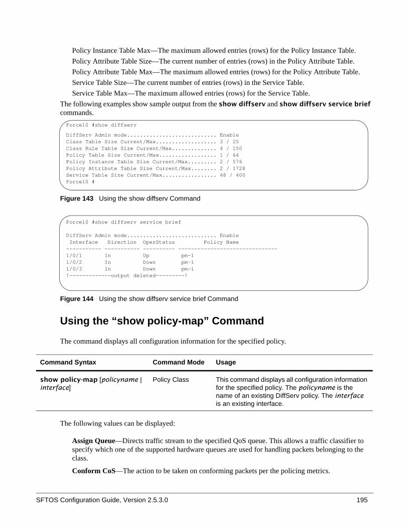
SFTOS Configuration Guide, Version 2.5.3.0 195
Policy Instance Table Max—The maximum allowed entries (rows) for the Policy Instance Table.Policy Attribute Table Size—The current number of entries (rows) in the Policy Attribute Table.Policy Attribute Table Max—The maximum allowed entries (rows) for the Policy Attribute Table.Service Table Size—The current number of entries (rows) in the Service Table.Service Table Max—The maximum allowed entries (rows) for the Service Table.
The following examples show sample output from the show diffserv and show diffserv service brief commands.
Figure 143 Using the show diffserv Command
Figure 144 Using the show diffserv service brief Command
Using the “show policy-map” Command
The command displays all configuration information for the specified policy.
The following values can be displayed:
Assign Queue—Directs traffic stream to the specified QoS queue. This allows a traffic classifier to specify which one of the supported hardware queues are used for handling packets belonging to the class.
Conform CoS—The action to be taken on conforming packets per the policing metrics.
Command Syntax Command Mode Usage
show policy-map [policyname | interface]
Policy Class This command displays all configuration information for the specified policy. The policyname is the name of an existing DiffServ policy. The interface is an existing interface.
Force10 #show diffserv
DiffServ Admin mode............................ EnableClass Table Size Current/Max................... 3 / 25Class Rule Table Size Current/Max.............. 4 / 150Policy Table Size Current/Max.................. 1 / 64Policy Instance Table Size Current/Max......... 2 / 576Policy Attribute Table Size Current/Max........ 2 / 1728Service Table Size Current/Max................. 48 / 400Force10 #
Force10 #show diffserv service brief
DiffServ Admin mode............................ Enable Interface Direction OperStatus Policy Name----------- ----------- ---------- -------------------------------1/0/1 In Up pm-11/0/2 In Down pm-11/0/3 In Down pm-1!-------------output deleted---------!
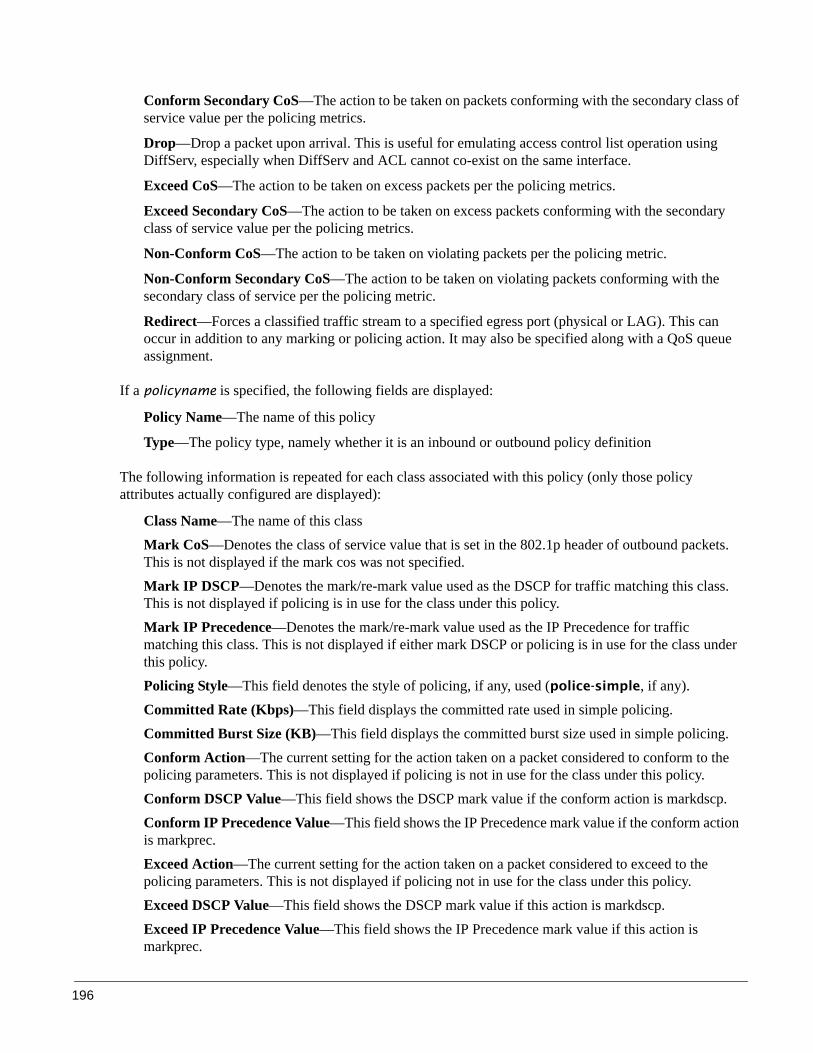
196
Conform Secondary CoS—The action to be taken on packets conforming with the secondary class of service value per the policing metrics.
Drop—Drop a packet upon arrival. This is useful for emulating access control list operation using DiffServ, especially when DiffServ and ACL cannot co-exist on the same interface.
Exceed CoS—The action to be taken on excess packets per the policing metrics.
Exceed Secondary CoS—The action to be taken on excess packets conforming with the secondary class of service value per the policing metrics.
Non-Conform CoS—The action to be taken on violating packets per the policing metric.
Non-Conform Secondary CoS—The action to be taken on violating packets conforming with the secondary class of service per the policing metric.
Redirect—Forces a classified traffic stream to a specified egress port (physical or LAG). This can occur in addition to any marking or policing action. It may also be specified along with a QoS queue assignment.
If a policyname is specified, the following fields are displayed:
Policy Name—The name of this policy
Type—The policy type, namely whether it is an inbound or outbound policy definition
The following information is repeated for each class associated with this policy (only those policy attributes actually configured are displayed):
Class Name—The name of this classMark CoS—Denotes the class of service value that is set in the 802.1p header of outbound packets. This is not displayed if the mark cos was not specified.Mark IP DSCP—Denotes the mark/re-mark value used as the DSCP for traffic matching this class. This is not displayed if policing is in use for the class under this policy.Mark IP Precedence—Denotes the mark/re-mark value used as the IP Precedence for traffic matching this class. This is not displayed if either mark DSCP or policing is in use for the class under this policy.Policing Style—This field denotes the style of policing, if any, used (police-simple, if any).Committed Rate (Kbps)—This field displays the committed rate used in simple policing.Committed Burst Size (KB)—This field displays the committed burst size used in simple policing.Conform Action—The current setting for the action taken on a packet considered to conform to the policing parameters. This is not displayed if policing is not in use for the class under this policy.Conform DSCP Value—This field shows the DSCP mark value if the conform action is markdscp.Conform IP Precedence Value—This field shows the IP Precedence mark value if the conform action is markprec.Exceed Action—The current setting for the action taken on a packet considered to exceed to the policing parameters. This is not displayed if policing not in use for the class under this policy.Exceed DSCP Value—This field shows the DSCP mark value if this action is markdscp.Exceed IP Precedence Value—This field shows the IP Precedence mark value if this action is markprec.

SFTOS Configuration Guide, Version 2.5.3.0 197
Non-Conform Action—The current setting for the action taken on a packet considered to not conform to the policing parameters. This is not displayed if policing not in use for the class under this policy.Non-Conform DSCP Value—This field displays the DSCP mark value if this action is markdscp.Non-Conform IP Precedence Value—This field displays the IP Precedence mark value if this action is markprec.Bandwidth—This field displays the minimum amount of bandwidth reserved in either percent or kilobits-per-second.Expedite Burst Size (KBytes)—This field displays the maximum guaranteed amount of bandwidth reserved in either percent or kilobits-per-second format.Shaping Average—This field is displayed if average shaping is in use. Indicates whether average or peak rate shaping is in use, along with the parameters used to form the traffic shaping criteria, such as CIR and PIR. This is not displayed if shaping is not configured for the class under this policy.Shape Committed Rate (Kbps)—This field is displayed if average or peak rate shaping is in use. It displays the shaping committed rate in kilobits-per-second.
The following is sample output from show policy-map:
Figure 145 show policy-map Command Example
If the policy name is not specified, as shown above, this command displays a list of all defined DiffServ policies. The following fields are displayed:
Policy Name—The name of this policy
Policy Type—The policy type, namely whether it is an inbound or outbound policy definition
Class Members—List of all class names associated with this policy
Note: The order in which the policies are displayed is not necessarily the same order in which they were created.
Force10 #show policy-map
Policy Name Policy Type Class Members------------------------------- ----------- -------------------------------pm-1 In cl-map-1 cl-map-2
Force10 #
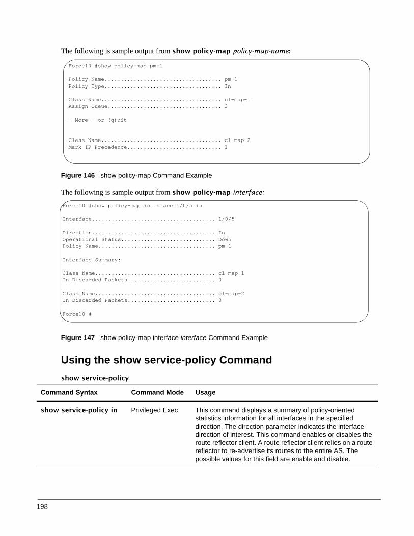
198
The following is sample output from show policy-map policy-map-name:
Figure 146 show policy-map Command Example
The following is sample output from show policy-map interface:
Figure 147 show policy-map interface interface Command Example
Using the show service-policy Commandshow service-policy
Command Syntax Command Mode Usage
show service-policy in Privileged Exec This command displays a summary of policy-oriented statistics information for all interfaces in the specified direction. The direction parameter indicates the interface direction of interest. This command enables or disables the route reflector client. A route reflector client relies on a route reflector to re-advertise its routes to the entire AS. The possible values for this field are enable and disable.
Force10 #show policy-map pm-1
Policy Name.................................... pm-1Policy Type.................................... In
Class Name..................................... cl-map-1Assign Queue................................... 3
--More-- or (q)uit
Class Name..................................... cl-map-2Mark IP Precedence............................. 1
Force10 #show policy-map interface 1/0/5 in
Interface...................................... 1/0/5
Direction...................................... InOperational Status............................. DownPolicy Name.................................... pm-1
Interface Summary:
Class Name..................................... cl-map-1In Discarded Packets........................... 0
Class Name..................................... cl-map-2In Discarded Packets........................... 0
Force10 #
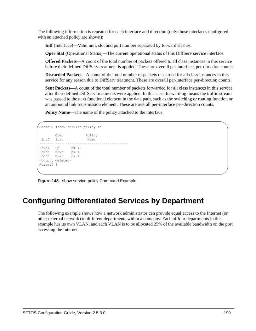
SFTOS Configuration Guide, Version 2.5.3.0 199
The following information is repeated for each interface and direction (only those interfaces configured with an attached policy are shown):
Intf (Interface)—Valid unit, slot and port number separated by forward slashes.
Oper Stat (Operational Status)—The current operational status of this DiffServ service interface.
Offered Packets—A count of the total number of packets offered to all class instances in this service before their defined DiffServ treatment is applied. These are overall per-interface, per-direction counts.
Discarded Packets—A count of the total number of packets discarded for all class instances in this service for any reason due to DiffServ treatment. These are overall per-interface per-direction counts.
Sent Packets—A count of the total number of packets forwarded for all class instances in this service after their defined DiffServ treatments were applied. In this case, forwarding means the traffic stream was passed to the next functional element in the data path, such as the switching or routing function or an outbound link transmission element. These are overall per-interface per-direction counts.
Policy Name—The name of the policy attached to the interface.
Figure 148 show service-policy Command Example
Configuring Differentiated Services by DepartmentThe following example shows how a network administrator can provide equal access to the Internet (or other external network) to different departments within a company. Each of four departments in this example has its own VLAN, and each VLAN is to be allocated 25% of the available bandwidth on the port accessing the Internet.
Force10 #show service-policy in
Oper Policy Intf Stat Name------- ---- -------------------------------1/0/1 Up pm-11/0/2 Down pm-11/0/3 Down pm-1<output deleted>Force10 #

200
Figure 149 DiffServ Internet Access Example Network Diagram
1. Ensure DiffServ operation is enabled for the switch.
2. Create a DiffServ class of type all for each of the departments, and name them. Define the match criteria—VLAN ID—for the new classes. .
Figure 150 Example of Using class-map Command
3. Create a DiffServ policy for inbound traffic named “internet_access”, adding the previously created department classes as instances within this policy. This policy uses the assign-queue attribute to put
VLAN 10:Finance
Internet
Port 0/5:Outbound
Layer 3 Switch
VLAN 20:Marketing
VLAN 30:Test
VLAN 40:Development
Port 0/2Port 0/1
Port 0/3
Port 0/4
Force10 #configForce10 (Config)#diffserv
Force10 (Config)#class-map match-all finance_deptForce10 (Config class-map)#match vlan 10Force10 (Config class-map)#exitForce10 (Config)#Force10 (Config)#class-map match-all marketing_deptForce10 (Config class-map)#match vlan 20Force10 (Config class-map)#exitForce10 (Config)#Force10 (Config)#class-map match-all test_deptForce10 (Config class-map)#match vlan 30Force10 (Config class-map)#exitForce10 (Config)#Force10 (Config)#class-map match-all development_deptForce10 (Config class-map)#match vlan 40Force10 (Config class-map)#exit

SFTOS Configuration Guide, Version 2.5.3.0 201
each department's traffic on a different egress queue. This is how the DiffServ inbound policy connects to the CoS queue settings established below..
Figure 151 Example of Using policy-map Command
4. DiffServ inbound configuration: Attach the defined policy to interfaces 1/0/10 through 1/0/13 in the inbound direction.
Figure 152 Example of Using service-policy Command
5. Set the CoS queue configuration for the (presumed) egress interface 1/0/14 such that each of queues 1, 2, 3, and 4 get a minimum guaranteed bandwidth of 25%. All queues for this interface use weighted round-robin scheduling by default. The DiffServ inbound policy designates that these queues are to be used for the departmental traffic through the assign-queue attribute. It is presumed that the switch will forward this traffic to interface 1/0/14, based on a normal destination address lookup for internet traffic.
Figure 153 Example of Using cos-queue Command
Force10 (Config)#policy-map internet_access inForce10 (Config-policy-map)#class finance_deptForce10 (Config-policy-classmap)#assign-queue 1Force10 (Config-policy-classmap)#exitForce10 (Config-policy-map)#class marketing_deptForce10 (Config-policy-classmap)#assign-queue 2Force10 (Config-policy-classmap)#exitForce10 (Config-policy-map)#class test_deptForce10 (Config-policy-classmap)#assign-queue 3Force10 (Config-policy-classmap)#exitForce10 (Config-policy-map)#class development_deptForce10 (Config-policy-classmap)#assign-queue 4Force10 (Config-policy-classmap)#exitForce10 (Config-policy-map)#exitForce10 (Config)#
Force10 (Config)#interface 1/0/10Force10 (Interface 1/0/10)#service-policy in internet_accessForce10 (Interface 1/0/10)#exitForce10 (Config)#interface 1/0/11Force10 (Interface 1/0/11)#service-policy in internet_accessForce10 (Interface 1/0/11)#exitForce10 (Config)#interface 1/0/12Force10 (Interface 1/0/12)#service-policy in internet_accessForce10 (Interface 1/0/12)#exitForce10 (Config)#interface 1/0/13Force10 (Interface 1/0/13)#service-policy in internet_accessForce10 (Interface 1/0/13)#exit
Force10 (Config)#interface 1/0/14Force10 (Interface 1/0/14)#cos-queue min-bandwidth 0 25 25 25 25 0 0 0Force10 (Interface 1/0/14)#exitForce10 (Config)#exit

202
Configuring Differentiated Services for Voice over IPOne of the most valuable uses of DiffServ is to support Voice over IP (VoIP). VoIP traffic is inherently time-sensitive. For a network to provide acceptable service, a guaranteed transmission rate is vital. This example shows one way to provide the necessary quality of service: how to set up a class for UDP traffic, have that traffic marked on the inbound side, and then expedite the traffic on the outbound side. The configuration sequence is for Router 1 in the accompanying diagram: a similar configuration should be applied to Router 2.
Figure 154 DiffServ VoIP Example Network Diagram
1 2 3
4 5 67 8 9
* 8 #
Port 0/2
Port 0/3
Lauer 3 Switchoperating as
Router 1
Layer 3 Switchoperating as
Router 2
Internet

SFTOS Configuration Guide, Version 2.5.3.0 203
1. Enter Global Config mode. Set queue 5 on all ports to use strict priority mode. This queue shall be used for all VoIP packets. Activate DiffServ for the switch.
2. Create a DiffServ classifier named “class_voip” and define a single match criterion to detect UDP packets. The class type match-all indicates that all match criteria defined for the class must be satisfied in order for a packet to be considered a match.
3. Create a second DiffServ classifier named “class_ef”, and define a single match criterion to detect a DiffServ code point (DSCP) of EF (expedited forwarding). This handles incoming traffic that was previously marked as expedited somewhere in the network.
4. Create a DiffServ policy for inbound traffic named “pol_voip”, then add the previously created classes class_ef and class_voip as instances within this policy. This policy handles incoming packets already marked with a DSCP value of EF (per the class_ef definition), or marks UDP packets per the class_voip definition) with a DSCP value of EF. In each case, the matching packets are assigned internally to use queue 5 of the egress port to which they are forwarded.
5. Attach the defined policy to an inbound service interface.
Force10 #configForce10 (Config)#cos-queue strict 5Force10 (Config)#diffserv
Force10 (Config)#class-map match-all class_voipForce10 (Config class-map)#match protocol udpForce10 (Config class-map)#exitForce10 (Config)#
Force10 (Config)#class-map match-all class_efForce10 (Config class-map)#match ip dscp efForce10 (Config class-map)#exitForce10 (Config)#
Force10 (Config)#policy-map pol_voip inForce10 (Config-policy-map)#class class_efForce10 (Config-policy-class-map)#assign-queue 5Force10 (Config-policy-class-map)#exitForce10 (Config-policy-map)#class class_voipForce10 (Config-policy-class-map)#mark ip-dscp efForce10 (Config-policy-class-map)#assign-queue 5Force10 (Config-policy-class-map)#exitForce10 (Config-policy-map)#exit
Force10 (Config)#interface 1/0/2Force10 (Interface 1/0/2)#service-policy in pol_voipForce10 (Interface 1/0/2)#exitForce10 (Config)#exitForce10 #

204
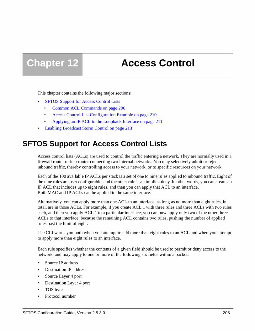
SFTOS Configuration Guide, Version 2.5.3.0 205
This chapter contains the following major sections:
• SFTOS Support for Access Control Lists• Common ACL Commands on page 206• Access Control List Configuration Example on page 210• Applying an IP ACL to the Loopback Interface on page 211
• Enabling Broadcast Storm Control on page 213
SFTOS Support for Access Control ListsAccess control lists (ACLs) are used to control the traffic entering a network. They are normally used in a firewall router or in a router connecting two internal networks. You may selectively admit or reject inbound traffic, thereby controlling access to your network, or to specific resources on your network.
Each of the 100 available IP ACLs per stack is a set of one to nine rules applied to inbound traffic. Eight of the nine rules are user configurable, and the other rule is an implicit deny. In other words, you can create an IP ACL that includes up to eight rules, and then you can apply that ACL to an interface. Both MAC and IP ACLs can be applied to the same interface.
Alternatively, you can apply more than one ACL to an interface, as long as no more than eight rules, in total, are in those ACLs. For example, if you create ACL 1 with three rules and three ACLs with two rules each, and then you apply ACL 1 to a particular interface, you can now apply only two of the other three ACLs to that interface, because the remaining ACL contains two rules, pushing the number of applied rules past the limit of eight.
The CLI warns you both when you attempt to add more than eight rules to an ACL and when you attempt to apply more than eight rules to an interface.
Each rule specifies whether the contents of a given field should be used to permit or deny access to the network, and may apply to one or more of the following six fields within a packet:
• Source IP address• Destination IP address• Source Layer 4 port• Destination Layer 4 port• TOS byte• Protocol number
Chapter 12 Access Control

206
Note that the order of the rules is important: when a packet matches multiple rules in an ACL, the first rule created in the ACL takes precedence. Also, once you define an ACL for a given port, all traffic not specifically permitted by the ACL will be denied access.
Loopback interface ACL: For IP ACLs, the priority given to an ACL assigned to the loopback interface affects the number of and order in which rules are applied to ports, just as if the ACL and its priority setting were assigned to each port. For details, see Protecting the Management Interface with a Loopback ACL on page 210.
SFTOS supports two types of filtering: extended MAC ACLs and IP ACLs. For both types, the general process for using them is the same:
1. Create the access list.
2. Apply the access list either globally to all ports or to an individual interface.
Common ACL Commands
MAC ACL CommandsMAC Access Control Lists (ACLs) ensure that only authorized users have access to specific resources and block any unwarranted attempts to reach network resources.
The following rules apply to MAC ACLs:
• The maximum number of ACLs you can create is 100, regardless of type.• The system supports only Ethernet II frame types.• The maximum number of rules per MAC ACL is hardware-dependent.• On the S50 system, if you configure an IP ACL (see IP ACL Commands on page 208) on an interface,
you cannot configure a MAC ACL on the same interface.
To create a MAC ACL identified by name:
— mac access-list extended name
Force10 (Config)#mac access-list extended ml-1
Define rules for the selected MAC ACL, consisting of classification fields defined for the Layer 2 header of an Ethernet frame:
Note: For syntax details on ACL commands, see the Quality of Service chapter in the SFTOS Command Reference.

SFTOS Configuration Guide, Version 2.5.3.0 207
— {deny|permit}{srcmac | any} {dstmac | any} [assign-queue queue-id_0-6] [cos 0-7] [ethertypekey] [0x0600-0xFFFF] [redirect unit/slot/port] [vlan {eq 0-4095]
Figure 155 Creating a Rule for a MAC Access List
Each rule is appended to the list of configured rules for the list. Note that an implicit “deny all” MAC rule always terminates the access list.
• Change the name of a MAC ACL. This command fails if a MAC ACL identified by the name newname already exists:— mac access-list extended rename name newname
• Attach a MAC ACL identified by name to the selected interface in the ingress direction. The name parameter must be the name of an existing MAC ACL. The optional 1-4294967295 parameter helps to set the order in which ACLs are applied to the interface if more than one ACL is assigned.— mac access-group name [1-4294967295] in
Force10 (Config)#interface 1/0/2
Force10 (Interface 1/0/2)#mac access-group ml-1 in
• Remove the assignment of a MAC ACL identified by name from the selected interface:— no mac access-group name
• Display a MAC ACL and all of the rules that are defined for the ACL. The name parameter identifies the MAC ACL to display:— show mac access-list name
Figure 156 Sample Output from show mac access-list Command
• Display a summary of all defined MAC access lists in the system:
Note: You can add new deny/permit list items to an existing list, but you cannot remove previously configured deny/permit list items. You must delete the list before recreating it as you want.
Force10 (Config)#mac access-list extended ml-1Force10 (Config-mac-access-list)#permit 01:80:c2:00:00:00 any assign-queue 4Force10 (Config-mac-access-list)#permit any 01:80:c2:00:00:FF assign-queue 3 redirect 1/0/10
Force10 #show mac access-list ml-1Rule Number: 1Action......................................... permitSource MAC Address............................. 01:80:C2:00:00:00Assign Queue................................... 4
Rule Number: 2Action......................................... permitDestination MAC Address........................ 01:80:C2:00:00:FFAssign Queue................................... 3Redirect Interface............................. 1/0/10
Force10 #

208
— show mac access-lists
Figure 157 Sample Output from show mac access-lists Command
IP ACL Commands
IP ACLs ensure that only authorized users have access to specific resources and block any unwarranted attempts to reach network resources.
The following rules apply to IP ACLs:
• SFTOS does not support IP ACL configuration for IP packet fragments.• The maximum number of ACLs you can create is 100, regardless of type.• The maximum number of rules per IP ACL is hardware dependent.• On S-Series systems, if you configure a MAC ACL (see MAC ACL Commands on page 206) on an
interface, you cannot configure an IP ACL on the same interface. • Wildcard masking for ACLs operates differently from a subnet mask. A wildcard mask is in essence
the inverse of a subnet mask. With a subnet mask, the mask has ones (1's) in the bit positions that are used for the network address, and has zeros (0's) for the bit positions that are not used. In contrast, a wildcard mask has (0’s) in a bit position that must be checked. A ‘1’ in a bit position of the ACL mask indicates the corresponding bit can be ignored.
The access-list command creates an IP ACL that is identified by the parameter ACLnumber, rendered as 1-99 for a Standard IP ACL or 100-199 for an Extended IP ACL, as discussed next.
Standard IP ACLs
A Standard IP ACL uses a list number in the range of 1-99, matches source IP address, then takes the action of assigning the packet to a queue and/or redirecting the packet to a destination port.
access-list 1-99 {deny | permit} {every | srcip srcmask} [log] [assign-queue queue-id] [{mirror | redirect} unit/slot/port]
Extended IP ACLs
An extended IP ACL uses a list number in the range of 100-199, matches protocol type, then matches source and/or destination ip address/port, additionally matches ip-precedence, tos, dscp, then takes the action of assigning the packet to a queue and/or redirecting the packet to a destination port. The command has the general form:
Force10 #show mac access-listsCurrent number of all ACLs: 3 Maximum number of all ACLs: 100
MAC ACL Name Rules Interface(s) Direction------------------------------- ----- ------------------------- ---------ml-1 2 1/0/2 inboundForce10 (Config-mac-access-list)#permit any 01:80:c2:00:00:FF assign-queue 3 redirect 1/0/10

SFTOS Configuration Guide, Version 2.5.3.0 209
access-list 100-199 {deny | permit} {every | icmp | igmp | ip | tcp | udp | protocol_number} {any | srcip srcmask} {any | eq {portkey | 0-65535}{any | dstip dstmask} [eq {portkey | 0-65535}] [precedence precedence | tos tos tosmask | dscp dscp] [log] [assign-queue queue-id] [{mirror | redirect} unit/slot/port]
Figure 158 Using the access-list Command for an Extended IP ACL Rule
• Attach a specified ACL to the selected interface:
— ip access-group ACLnumber [1-4294967295] in
The optional 1-4294967295 variable is an integer that indicates the order of application of this ACL relative to other ACLs assigned to this interface.
Figure 159 Using the ip access-group Command
When the ip access-group command is used in Interface Config mode, it attaches a specified ACL to the selected interface. In Global Config mode, the command attaches a specified ACL to all interfaces.
• Display a summary of all created IP Access Control Lists (ACLs), or details about the rules that are defined for a specific ACL:— show ip access-lists [ACLnumber]
Figure 160 Sample show ip access-lists Command Output
Note: In both versions of the access-list command, above, srcmask is an inverse mask.Note: You cannot edit a rule once it is created, you must delete the list and create one as desired.
Force10 (Config)#access-list 100 permit ip any eq 80 any assign-queue 2 redirect 1/0/40Force10 (Config)#
Force10 (Config)#interface 1/0/21Force10 (Interface 1/0/21)#ip access-group 100 1 in
Force10 #show ip access-listsCurrent number of ACLs: 2 Maximum number of ACLs: 100ACL ID Rules Interface(s) Direction------ ----- ------------------------- ---------1 1100 1 1/0/21 inbound
Force10 #show ip access-lists 100ACL ID: 100Interface: 1/0/21
Rule Number: 1Action......................................... permitMatch All...................................... FALSEProtocol....................................... 255(ip)Source L4 Port Keyword......................... 80(www/http)Assign Queue................................... 2Redirect Interface............................. 1/0/40
Force10 #

210
Protecting the Management Interface with a Loopback ACL
Added in SFTOS 2.5.1, the loopback interface is a virtual interface in which the software emulates an interface. Basically, the loopback interface is a handle controlling access to the CPU interface. When configuring an ACL on the loopback interface, the ACL is applied to all physical interfaces in the system.
1. The interface loopback 0 command creates the interface and invokes its own version of the Interface Config mode — Interface Loopback Config mode — the prompt is (Interface loopback 0)#. Commands that are available from Interface Config mode are also available in Interface Loopback Config mode.
2. Within that mode, use the ip access-group ACLnumber in command to assign the appropriate ACLs (see Figure 159 on page 209). For a configuration example, see Applying an IP ACL to the Loopback Interface on page 211.
Access Control List Configuration Example
The following example shows how to set up an IP ACL with two rules—one for TCP traffic and one for UDP traffic. The content of the two rules is the same. TCP and UDP packets will only be accepted by the switch if the source and destination stations have IP addresses that are within defined sets.
Figure 161 ACL Example Network Diagram
Port 0/2ACL 1
192.168.77.1 192.168.77.2192.168.77.9192.168.77.4
TCP packet to192.178.77.3 accepted:
Dest. IP in range
TCP packet to192.178.88.3 rejected:Dest. IP not in range
Layer 2 Switch
Layer 3 Switch
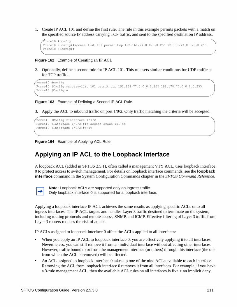
SFTOS Configuration Guide, Version 2.5.3.0 211
1. Create IP ACL 101 and define the first rule. The rule in this example permits packets with a match on the specified source IP address carrying TCP traffic, and sent to the specified destination IP address.
Figure 162 Example of Creating an IP ACL
2. Optionally, define a second rule for IP ACL 101. This rule sets similar conditions for UDP traffic as for TCP traffic.
Figure 163 Example of Defining a Second IP ACL Rule
3. Apply the ACL to inbound traffic on port 1/0/2. Only traffic matching the criteria will be accepted.
Figure 164 Example of Applying ACL Rule
Applying an IP ACL to the Loopback Interface
A loopback ACL (added in SFTOS 2.5.1), often called a management VTY ACL, uses loopback interface 0 to protect access to switch management. For details on loopback interface commands, see the loopback interface command in the System Configuration Commands chapter in the SFTOS Command Reference.
Applying a loopback interface IP ACL achieves the same results as applying specific ACLs onto all ingress interfaces. The IP ACL targets and handles Layer 3 traffic destined to terminate on the system, including routing protocols and remote access, SNMP, and ICMP. Effective filtering of Layer 3 traffic from Layer 3 routers reduces the risk of attack.
IP ACLs assigned to loopback interface 0 affect the ACLs applied to all interfaces:
• When you apply an IP ACL to loopback interface 0, you are effectively applying it to all interfaces. Nevertheless, you can still remove it from an individual interface without affecting other interfaces. However, traffic bound to or from the management interface (or others) through this interface (the one from which the ACL is removed) will be affected.
• An ACL assigned to loopback interface 0 takes up one of the nine ACLs available to each interface. Removing the ACL from loopback interface 0 removes it from all interfaces. For example, if you have a 3-rule management ACL, then the available ACL rules on all interfaces is five + an implicit deny.
Note: Loopback ACLs are supported only on ingress traffic. Only loopback interface 0 is supported for a loopback interface.
Force10 #configForce10 (Config)#access-list 101 permit tcp 192.168.77.0 0.0.0.255 92.178.77.0 0.0.0.255Force10 (Config)#
Force10 #configForce10 (Config)#access-list 101 permit udp 192.168.77.0 0.0.0.255 192.178.77.0 0.0.0.255Force10 (Config)#
Force10 (Config)#interface 1/0/2Force10 (Interface 1/0/2)#ip access-group 101 inForce10 (Interface 1/0/2)#exit

212
• An ACL applied to loopback interface 0 appears under the configuration for each interface in the running-config, not under loopback interface 0.
• You can remove an IP ACL from all interfaces to which it has been individually assigned by executing a no ip access-group command from Interface Loopback Config mode. For example, if ACL 1 is assigned to ports 1/0/2 and 1/0/4, executing the no ip access-group 1 command from Interface Loopback Config mode removes the ACL from those two ports.
• The priority assigned to the loopback ACL affects the order in which ACL rules are applied to interfaces. For example, if you assign priority 10 to the loopback ACL, and you assign priority 9 to ACL 1 assigned directly to a particular port, the rules in ACL 1 take precedence. (Priority 9 is higher than priority 10.)
To apply an ACL (standard or extended) for loopback, use the following sequence:
Restrictions on the usage of loopback interface ACL
As noted above, applying an ACL to loopback interface 0 in turn applies the ACL to all physical interfaces. To configure additional ACLs on a physical interface, be aware that the “loopback interface ACL” might conflict with the desired physical interface ACL behavior.
Step Command SyntaxCommand Mode Purpose
1 • For a Standard IP ACL: access-list 1-99 {deny | permit} {every | srcip srcmask} [log] [assign-queue queue-id] [{mirror | redirect} unit/slot/port]
• For an Extended IP ACL:access-list 100-199 {deny | permit} {every | icmp | igmp | ip | tcp | udp | protocol_number} {any | srcip srcmask} {any | eq {portkey | 0-65535}{any | dstip dstmask} [eq {portkey | 0-65535}] [precedence precedence | tos tos tosmask | dscp dscp] [log] [assign-queue queue-id] [redirect unit/slot/port]
Global Config
Create an IP ACL.Note: The mirror option is only available for the S50V and S25P.
2 interface loopback 0 Global Config
Create the loopback interface and access the Interface Config mode.
3 ip access-group ACLnumber [seq] in Interface Config
Attach the specified ACL to the loopback interface.
4 show ip access-lists [ACLnumber] Privileged Exec
Display rules associated with the specified ACL.
5 show interface loopback 0 Privileged Exec
Display the loopback configuration.

SFTOS Configuration Guide, Version 2.5.3.0 213
Example of loopback interface configuration sequence
In the following example, two rules are added to ACL 2, and then ACL 2 is applied to the loopback interface.
Figure 165 Loopback ACL Example
Enabling Broadcast Storm Control A broadcast storm occurs when incoming packets flood the LAN, degrading network performance. SFTOS provides broadcast storm control at a global (switch) level, not for individual interfaces.
To enable storm control, execute the command storm-control broadcast in Global Config mode. Disable storm control with the command no storm-control broadcast.
Broadcast storm control is implemented in SFTOS with automated high and low thresholds that are based on a percentage of link speed. If broadcast traffic on any port exceeds the high threshold percentage (as represented in the following table) of the link speed, the switch discards the broadcast traffic until the traffic returns to the low threshold percentage or less.
Table 7 Broadcast Storm Control Thresholds
Link Speed High Low
10M 20 10
100M 5 2
1000M 5 2
Force10 (Config)#access-list 2 permit everyForce10 (Config)#access-list 2 deny 10.240.4.113 255.255.255.0Force10 (Config)#interface loopback 0Force10 (Conf-if-lo-0)# ip access-group 2 in 10Force10 (Conf-if-lo-0)# exitForce10 #show ip access-lists 2
ACL ID: 2Interface :loopback
Rule Number: 1Action......................................... permitMatch All...................................... TRUE
Rule Number: 2Action......................................... denyMatch All...................................... FALSESource IP Address.............................. 10.240.4.113Source IP Mask................................. 255.255.255.0--More-- or (q)uit
10 is the priority, an optional parameter.

214
Use the show storm-control command to verify the setting.
Use the show interface-ethernet unit/slot/port command to see the number of packets not forwarded (highlighted in Figure 166) in a broadcast storm condition when broadcast storm control has been implemented.
Figure 166 Using the show interface-ethernet Command
Force10 #show interface ethernet 1/0/2
Type........................................... NormalAdmin Mode..................................... EnablePhysical Mode.................................. AutoPhysical Status................................ DownSpeed.......................................... 0 - NoneLink Status.................................... DetachMAC Address.................................... 0001.E8D5.A058Total Packets Received (Octets)................ 0Packets Received > 1522 Octets................. 0Packets RX and TX 64 Octets.................... 0Packets RX and TX 65-127 Octets................ 0Packets RX and TX 128-255 Octets............... 0Packets RX and TX 256-511 Octets............... 0Packets RX and TX 512-1023 Octets.............. 0Packets RX and TX 1024-1518 Octets............. 0Packets RX and TX 1519-1522 Octets............. 0Packets RX and TX 1523-2047 Octets............. 0Packets RX and TX 2048-4095 Octets............. 0Packets RX and TX 4096-9216 Octets............. 0Total Packets Received Without Errors.......... 0Unicast Packets Received....................... 0Multicast Packets Received..................... 0Broadcast Packets Received..................... 0Total Packets Received with MAC Errors......... 0Jabbers Received............................... 0Fragments Received............................. 0Undersize Received............................. 0Alignment Errors............................... 0FCS Errors..................................... 0Overruns....................................... 0Total Received Packets Not Forwarded........... 0Local Traffic Frames........................... 0802.3x Pause Frames Received................... 0Unacceptable Frame Type........................ 0Multicast Tree Viable Discards................. 0Broadcast Storm Recovery....................... 0CFI Discards................................... 0Upstream Threshold............................. 0!------------[output omitted]--------------!
storm control

SFTOS Configuration Guide, Version 2.5.3.0 215
This chapter describes the use of SFTOS to create IEEE 802.1Q Virtual LANs (VLANs); it contains the following major sections:
• Introduction to VLAN Configuration on page 215• Important Points to Remember on page 216• Implementing VLANs on page 217• VLAN Mode Commands on page 218• Configuration Task List for VLANs on page 219• Adding a LAG to a VLAN on page 223• Creating a Routed VLAN on page 225• GARP and GVRP on page 227• Creating an IP Subnet-based VLAN on page 231• Configuring a Private Edge VLAN (PVLAN) on page 232• Configuring a Native VLAN on page 233• Configuring a VLAN Tunnel (DVLAN or VLAN-Stack) on page 238• Displaying VLAN Information on page 242
Introduction to VLAN ConfigurationVirtual LAN (VLAN) support in SFTOS conforms to the IEEE 802.1Q specification, allowing a network to be logically segmented without regard to the physical location of devices on the network—one physical network becomes multiple logical networks. These logical networks may, or may not, correspond to subnets.
While maintaining Layer 2 forwarding speed, network segmentation provides:
• Better administration• Better security• Better management of multicast traffic
Adding Virtual LAN (VLAN) support to a Layer 2 switch offers some of the benefits of both bridging and routing. Like a bridge, a VLAN switch forwards traffic based on the Layer 2 header, which is fast, and like a router, it partitions the network into logical segments, which provides better administration, security and management of multicast traffic.
Chapter 13 VLANs

216
A VLAN is a set of end stations and the switch ports that connect them. You may have many reasons for the logical division, such as department or project membership. The only physical requirement is that the end station and the port to which it is connected both belong to the same VLAN.
Each VLAN in a network has a VLAN ID, which appears in the IEEE 802.1Q tag in the Layer 2 header of packets transmitted on a VLAN. An end station may omit the tag, or the VLAN portion of the tag, in which case the first switch port to receive the packet may either reject it or insert a tag using its default VLAN ID. A given port may handle traffic for more than one VLAN, but it can only support one default VLAN ID.
SFTOS 2.5.1 introduced two other VLAN features:
• The Private Edge VLAN sets protection between ports located on the switch. A protected port cannot forward traffic to another protected port on the same switch. The feature does not provide protection between ports located on different switches. See Configuring a Private Edge VLAN (PVLAN) on page 232.
• The native VLAN provides the ability for a port to handle both tagged and untagged frames, in order to handle control plane traffic in the native VLAN while it also participates in another VLAN. See Configuring a Native VLAN on page 233.
Important Points to Remember• The default VLAN is VLAN 1. It cannot be changed. You cannot tag interfaces for VLAN 1.• A VLAN can include LAGs (port channels) and ports on multiple switches in the stack.• If a port is a member of multiple VLANs, it can be tagged in one VLAN and untagged in another.• With the SFTOS VLAN implementation, ports may belong to multiple tagged VLANs, and VLAN
membership may be based on port or protocol.• The internal bridging and routing functions can act as logical ports of each other when VLAN routing
is used.• 1024 VLANs can be in operation at one time, any of which can have a VLAN ID up to 3965. The top
129 VLANs are reserved.• Each interface must have a single native VLAN (tagged or untagged) at all times (see Configuring a
Native VLAN on page 233).• You can configure VLANs from either the Interface Range mode (see Bulk Configuration on
page 134) or Interface VLAN mode (see VLAN Mode Commands on page 218).• It is possible to set the management VLAN to a VLAN that does not exist. If you cannot reach
anything from the management IP address (see Creating the Management IP Address on page 75), check the management VLAN using show interface managementethernet or show running-config.

SFTOS Configuration Guide, Version 2.5.3.0 217
Implementing VLANs
When an individual port is added to a LAG, any VLAN membership is suspended. However, the membership is automatically restored when the port is removed from the LAG.
Forwarding Rules
Forwarding rules are based on the following attributes:
• VLAN membership• Spanning tree state (forwarding)• Frame type (unicast or multicast)• Filters
Egress Rules• Spanning tree state (forwarding)• VLAN membership• Untagged frames only forwarded if embedded addresses are canonical
Exempt Frames• Spanning tree BPDUs• GVRP BPDUs• Frames used for control purposes, e.g. LAG PDUs, flow control
Table 8 VLAN ID Options
VLAN ID Limitations
0 Reserved for .1p
1 Default VLAN
2 - 3965 Configurable by user
3966 - 4094 Reserved for Layer 3 interfaces
4095 Reserved for Blackhole VLAN
4096 Total VLAN IDs

218
VLAN Mode CommandsThe starting point for VLAN command syntax statements is the VLAN Commands chapter (Chapter 7) in the SFTOS Command Reference.
Executing the interface vlan 2-4094 command (Global Config mode) either creates a VLAN or selects a previously created VLAN (or use [no] interface vlan 2-4094 to delete a VLAN) and then enters the Interface VLAN mode, where you have access to commands that configure the selected VLAN:
• To add an interface to the VLAN, use either the tagged intf-range or untagged intf-range command. The full syntax is:
• [no] tagged {intf-range [native] | port-channel port-channel-range}• [no] untagged {intf-range | port-channel port-channel-range}
• To change a dynamically created VLAN (see Using GVRP on page 228) to a static VLAN (permanently configure):— makestatic (in Interface VLAN mode)
• To [reset] assign a name to a VLAN (VLAN 1 is always named Default, while the default for other VLANs is a blank string.):— [no] name name (up to 32 alphanumeric characters)
• To configure the interface link layer encapsulation type:— encapsulation
• To configure IGMP Snooping parameters for the VLAN:— igmp
• To configure IP parameters, there are many command families:— For ip routing, use ip address and ip vrrp.— Multicast: For IP multicast, use [no] ip mcast boundary. For IGMP, use [no] ip igmp, [no] ip
igmp last-member-query-count, and others detailed in the IP Multicast Commands chapter in the SFTOS Command Reference.
— IP OSPF commands, such as ip ospf and ip ospf areaid areaid, are detailed in the OSPF Commands chapter in the SFTOS Command Reference.
— ip rip commands are detailed in the RIP Commands chapter in the SFTOS Command Reference.• To set the MTU (maximum transmission unit) size:
— [no] mtu 576-1500 (default is 1500)— [no] ip mtu 68-1500 for an MTU value for IP protocol
• To configure the protocols associated with particular group IDs:— protocol group groupid

SFTOS Configuration Guide, Version 2.5.3.0 219
Configuration Task List for VLANs• Creating a VLAN and Adding Ports• Clearing/Resetting a VLAN on page 222• Adding a LAG to a VLAN on page 223• Creating a Routed VLAN on page 225• Enabling Dynamic VLANs with GVRP on page 229• Creating an IP Subnet-based VLAN on page 231• Configuring a Private Edge VLAN (PVLAN) on page 232• Configuring a Native VLAN on page 233
For more VLAN configuration examples:
• In the Getting Started chapter, see introduction to VLAN configuration, Creating VLANS on page 49.• For more information on VLAN routing in this guide, see the VLAN section in Chapter 17, VLAN
Routing on page 270.
Creating a VLAN and Adding Ports
The following instructions are the basic configuration tasks for creating the VLAN and adding ports to it:
Note: Enable each port added to the VLAN.
Step Command Syntax Command Mode Usage
1 interface vlan 2-4094 Global Config Specify a new or existing VLAN by VLAN number.
2 [no] tagged unit/slot/port
Interface VLAN To add tagged ports to the VLAN, specify a single port in unit/slot/port format to add to the selected VLAN, or specify a sequential port range as unit/slot/port-unit/slot/port.
Specify a non-sequential port range as unit/slot/port,unit/slot/port,...Specify a LAG ID as an integer (List LAG IDs with show interface port-channel brief.)
3 [no] untagged unit/slot/port
Interface VLAN To add untagged ports to the VLAN, specify either a port, port range, port channel, or port channel range, as described above.
4 name VLAN-name Interface VLAN (OPTIONAL) Name the VLAN.
5 show vlan id vlanid Privileged Exec Verify the configuration.

220
Example of creating a VLAN and assigning interfaces
The diagram in this example shows four S-Series switches, R1, R2, R3, and R4, each configured with VLAN 2 to handle traffic destined for R1.
This example creates VLAN 2 to connect four switches, with each switch having an interface that connects through VLAN 2 to switch R1.
Figure 167 VLAN Topology
1. Create VLAN 2 on switch R1 and assign ports 20, 22, and 23:
2. Create VLAN 2 on switch R2 and assign port 1:
3. Create VLAN 2 on switch R3 and assign port 3:
4. Create VLAN 2 on switch R4 and assign port 4:
VLAN 2
R1 #configR1 (Config)#interface vlan 2R1 (Conf-if-vl-2)#untagged 1/0/20R1 (Conf-if-vl-2)#untagged 1/0/22R1 (Conf-if-vl-2)#untagged 1/0/23
R5 #configR5 (Config)#interface vlan 2R5 (Conf-if-vl-2)#untagged 1/0/1
R3 #configR3 (Config)#interface vlan 2R3 (Conf-if-vl-2)#tagged 1/0/3
R4 #configR4 (Config)#interface vlan 2R4 (Conf-if-vl-2)#untagged 1/0/4

SFTOS Configuration Guide, Version 2.5.3.0 221
5. Optionally, after creating the VLAN, you can name it using the name command. For example, if R1 in this example is providing access to the Internet, you might name the VLAN “Internet_through_R1” on each participating switch.
6. Verify the configuration with the show vlan commands, or any of the other commands listed in Displaying VLAN Information on page 242.
Notes:
• Note that VLAN2 on R1 has some untagged ports and some tagged ports. The tagging type (either untagged or tagged) must match those of their directly connected ports on the other switches.
• SFTOS 2.5 permits mixed tagged and untagged VLANs on an interface.
Assign an interface to multiple VLANs
The diagram in Figure 168 shows five S-Series switches, R1, R2, R3, R4, and R5, in a trunking relationship, where port 20 on R1 is connected through R5 on separate VLANs to the other three switches.
Figure 168 Switch Connected to Other Switches through Multiple VLANs
1. To create the topology shown in Figure 168, first create VLANs 2, 3, and 4 on switch R1, and assign port 20 to each VLAN.
2. Create VLAN 2 on switch R2 and assign port 1.
R1 #configR1 (Config)#interface vlan 2R1 (Conf-if-vl-2)#tagged 1/0/20R1 (Conf-if-vl-2)#exitR1 (Config)#interface vlan 3R1 (Conf-if-vl-3)#tagged 1/0/20R1 (Conf-if-vl-3)#exitR1 (Config)#interface vlan 4R1 (Conf-if-vl-4)#tagged 1/0/20
R2 #configR2 (Config)#interface vlan 2R2 (Conf-if-vl-2)#tagged 1/0/1

222
3. Create VLAN 4 on switch R3 and assign port 3.
4. Create VLAN 3 on switch R4 and assign port 4:
5. Create VLANs 2, 3, and 4 on switch R5 to connect to each member switch in the topology:
6. Verify the configuration with the show vlan commands, or any of the other commands listed in Displaying VLAN Information on page 242.
Notes:
• R1 has interface 1/0/20 in multiple VLANs.• R5 has interface 1/0/1 in multiple VLANs.• Note that all VLANs in this example are tagged, because an interface can be a member of multiple
tagged VLANs, but not multiple untagged VLANs.
Clearing/Resetting a VLAN
To clear the VLAN configuration parameters to the factory defaults, issue the clear vlan command from Privileged Exec mode:
Figure 169 Example of Removing VLANs
The clear vlan command removes all VLAN information from the running configuration.
R3 #configR3 (Config)#interface vlan 4R3 (Conf-if-vl-4)#tagged 1/0/3
R4 #configR4 (Config)#interface vlan 3R4 (Conf-if-vl-3)#tagged 1/0/4
R5 #configR5 (Config)#interface vlan 2R5 (Conf-if-vl-2)#tagged 1/0/1R5 (Conf-if-vl-2)#tagged 1/0/4R5 (Conf-if-vl-2)#exitR5 (Config)#interface vlan 3R5 (Conf-if-vl-3)#tagged 1/0/1R5 (Conf-if-vl-3)#tagged 1/0/3R5 (Conf-if-vl-3)#exitR5 (Config)#interface vlan 4R5 (Conf-if-vl-4)#tagged 1/0/1R5 (Conf-if-vl-4)#tagged 1/0/2
Force10 #clear vlan
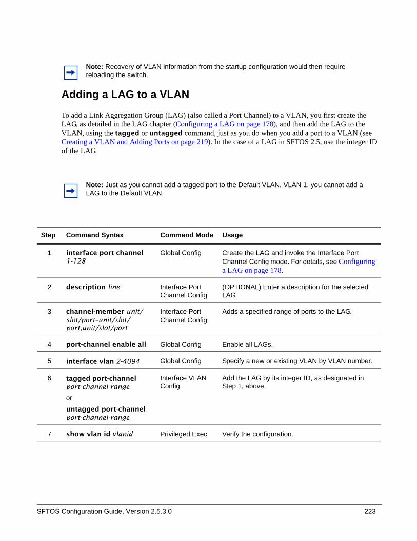
SFTOS Configuration Guide, Version 2.5.3.0 223
Adding a LAG to a VLAN
To add a Link Aggregation Group (LAG) (also called a Port Channel) to a VLAN, you first create the LAG, as detailed in the LAG chapter (Configuring a LAG on page 178), and then add the LAG to the VLAN, using the tagged or untagged command, just as you do when you add a port to a VLAN (see Creating a VLAN and Adding Ports on page 219). In the case of a LAG in SFTOS 2.5, use the integer ID of the LAG.
Note: Recovery of VLAN information from the startup configuration would then require reloading the switch.
Note: Just as you cannot add a tagged port to the Default VLAN, VLAN 1, you cannot add a LAG to the Default VLAN.
Step Command Syntax Command Mode Usage
1 interface port-channel 1-128
Global Config Create the LAG and invoke the Interface Port Channel Config mode. For details, see Configuring a LAG on page 178.
2 description line Interface Port Channel Config
(OPTIONAL) Enter a description for the selected LAG.
3 channel-member unit/slot/port–unit/slot/port,unit/slot/port
Interface Port Channel Config
Adds a specified range of ports to the LAG.
4 port-channel enable all Global Config Enable all LAGs.
5 interface vlan 2-4094 Global Config Specify a new or existing VLAN by VLAN number.
6 tagged port-channel port-channel-range
or
untagged port-channel port-channel-range
Interface VLAN Config
Add the LAG by its integer ID, as designated in Step 1, above.
7 show vlan id vlanid Privileged Exec Verify the configuration.

224
Example of adding a LAG to a VLAN
Figure 170 Adding a LAG to a VLAN
1. To create the topology shown in Figure 170, create the LAG on switch R1, giving it an integer ID (and, optionally, a description — the “admin1” shown here). Add ports to it, and enable it (use either the no shutdown command inside the Interface Port Channel mode, or use the global mode shown here).
Figure 171 Creating a LAG and Adding Ports
2. Create VLAN 300 and add the LAG to it on switch R1.
Figure 172 Adding a LAG to a VLAN
3. Repeat the above sequence on switch R2.
4. Verify the operation on both switches.
Figure 173 Verifying a LAG in a VLAN with show vlan id and show port-channel id
R1 (Config)#interface port-channel 1R1 (conf-if-po- 1)#description “admin1”R1 (conf-if-po- 1)#channel-member 1/0/35-1/0/37R1 (Config)#exitR1 (Config)#port-channel enable all
R1 (Config)#interface vlan 300R1 (Conf-if-vl-300)#tagged port-channel 1
R2 #show vlan id 300
Codes: * - Default VLAN, G - GVRP VLANs, E - Ethernet interface
Vlan Id Status Q Ports ------- --------- - -------- 300 Active T Po1
R2 #show interfaces port-channel brief
LAG Status Ports --- ------ ------- 1 Down 1/0/35 (Down)
1/0/36 (Down) 1/0/37 (Down)

SFTOS Configuration Guide, Version 2.5.3.0 225
Creating a Routed VLAN
This section provides an example of how to configure an S-Series switch to enable VLAN routing. Your switch must be running a version of SFTOS that supports Layer 3 :
Step Command Syntax Command Mode Usage
1 ip routing Global Config Enable routing globally.
2 interface vlan vlan_id Global Config Specify a new or existing VLAN by VLAN number, from 2–4094.
3 ip address ip_address subnet_mask
Interface VLAN Config
Configure an IP address and subnet mask for the VLAN. Configuring an IP address on the VLAN implicitly enables routing functionality for the VLAN.
4 tagged unit/slot/port Interface VLAN Config
Add one or more ports to the VLAN.
5 show vlan id vlanid Privileged Exec Verify the configuration.
6 Repeat the steps above for any other S-Series router to which you want to communicate with this VLAN.
Note: In addition to the example of a routed VLAN, below, another example is in the Routing chapter. See VLAN Routing Configuration on page 267.

226
Example of creating a routed VLAN on one switch
Figure 174 Diagram of a Routed VLAN
1. Enable routing globally on the switch:
Figure 175 Enabling Routing Globally on a Switch
2. Enable ports:
3. Create an IP VLAN (a routed VLAN) on switch R1and add port 2 to it:
Figure 176 Creating an IP VLAN
4. As above, create VLAN 3 on switch R5, add an IP address, subnet mask, and port 3 to it:
R5#configureR5 (Config)#ip routing
R5#configureR5 (Config)#interface 1/0/2R5 (Interface 1/0/2)#no shutdownR5 (Interface 1/0/2)#exitR5 (Config)#interface 1/0/3R5 (Interface 1/0/3)#no shutdownR5 (Interface 1/0/3)#exit
R5 (Config)#interface vlan 2R5 (Conf-if-vl-200)#ip address 10.10.1.1 255.255.255.0R5 (Conf-if-vl-200)#untagged 1/0/2
R5 (Config)#interface vlan 3R5 (Conf-if-vl-200)#ip address 10.10.2.1 255.255.255.0R5 (Conf-if-vl-200)#untagged 1/0/3

SFTOS Configuration Guide, Version 2.5.3.0 227
5. Verify configurations with the show vlan id command on each switch. See an example of the command output in Figure 198 on page 243.
Note: If routing is configured on a physical interface that is a member of a VLAN, the interface IS remove from the VLAN until routing is disabled on the interface, which restores the interface to the VLAN.
GARP and GVRP
This section contains these major subsections:
• GARP VLAN Registration Protocol (GVRP)• GARP Timers on page 228• GARP Commands on page 228• Using GVRP on page 228• Enabling Dynamic VLANs with GVRP on page 229• Displaying GARP, GVRP, GMRP Properties on page 230
Generic Attribute Registration Protocol (GARP) provides a generic attribute dissemination protocol used to support other protocols such as GVRP (GARP VLAN Registration Protocol. GARP is used to register and deregister attribute values with other GARP participants within bridged LANs. When a GARP participant declares or withdraws a given attribute, the attribute value is recorded with the applicant state machine for the port from which the declaration or withdrawal was made.
A GARP participant exists per port per GARP application (e.g. GVRP). For details on GARP, GVRP, and GMRP (GARP Multicast Registration Protocol) command syntax, see the GARP, GVRP, and GMRP Commands chapter in the SFTOS Command Reference.
GARP VLAN Registration Protocol (GVRP)• GVRP propagates VLAN membership throughout a network.• GVRP allows end stations and switches to issue and revoke declarations relating to VLAN
membership.• VLAN registration is made in the context of the port that receives the GARP PDU and is propagated to
the other active ports.• GVRP is disabled by default; you must enable GVRP for the switch and then for individual ports.• Dynamic VLANs are aged out after the LeaveAll Timer expires three times without receipt of a join
message.
Note: GARP and GVRP functionality existed in SFTOS prior to SFTOS 2.5.2.0, but it was not tested in SFTOS 2.5.2.0, so it is not supported.

228
GARP Timers
The following are GARP timers:
• Join Timer:— Controls the interval of a GMRP PDU transmission— Default value: 20 centiseconds
• Leave Timer:— Controls the time period after the de-registration process is started for a registered attribute. It
should be at least twice the Join Timer.— Default value: 60 centiseconds
• LeaveAll Timer:— Controls the frequency with which a LeaveAll event GARP PDU is transmitted. It should be
considerably longer than the Leave Timer.— Default value: 1000 centiseconds
GARP Commands
In Global Config mode, you can enable GVRP, or GMRP, or both for the switch:
gvrp adminmode enable
gmrp adminmode enable: enables GARP Multicast Registration Protocol (GMRP) on the system
gmrp interfacemode enable all: enables GARP Multicast Registration Protocol on all interfaces
In Interface Config mode, enable GVRP for a port:
gvrp interfacemode enable
In Interface Config, Global Config, or Interface Range mode, set the timer values in centiseconds. For interface-level changes, go to the individual interfaces to apply changes.
set garp timer join <10-100> The default is 20.
set garp timer leave <20-600> The default is 60.
set garp timer leaveall <200-6000> The default is 1000.
Using GVRP
GVRP is used to exchange a VLAN number—in this example, VLAN 3—dynamically from the switch on which it is configured to the switch on which GVRP is enabled.
• GVRP must be enabled globally and on selected interfaces.• One end must have a VLAN configured on an interface in order to establish a dynamic VLAN
connection on the other end. In the following example, R2 has VLAN 3 configured.
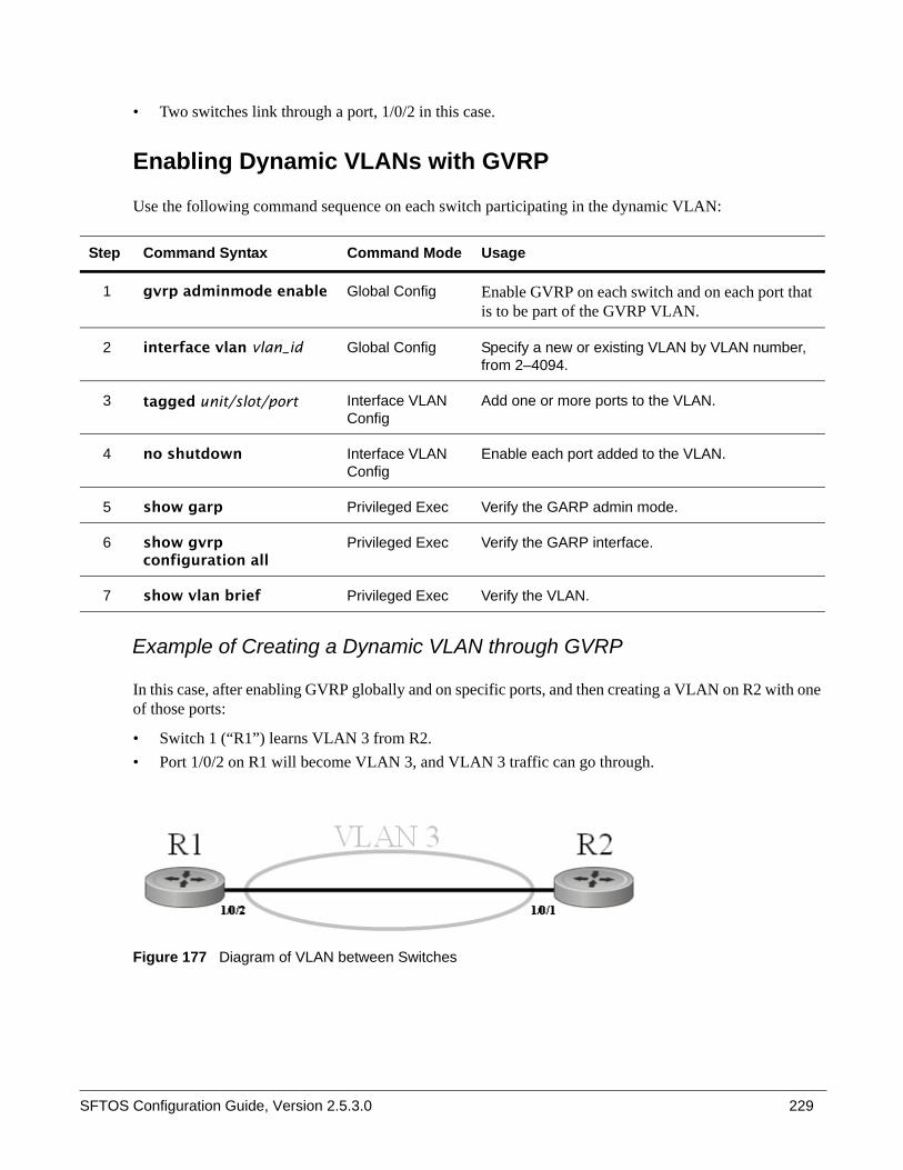
SFTOS Configuration Guide, Version 2.5.3.0 229
• Two switches link through a port, 1/0/2 in this case.
Enabling Dynamic VLANs with GVRP
Use the following command sequence on each switch participating in the dynamic VLAN:
Example of Creating a Dynamic VLAN through GVRP
In this case, after enabling GVRP globally and on specific ports, and then creating a VLAN on R2 with one of those ports:
• Switch 1 (“R1”) learns VLAN 3 from R2.• Port 1/0/2 on R1 will become VLAN 3, and VLAN 3 traffic can go through.
Figure 177 Diagram of VLAN between Switches
Step Command Syntax Command Mode Usage
1 gvrp adminmode enable Global Config Enable GVRP on each switch and on each port that is to be part of the GVRP VLAN.
2 interface vlan vlan_id Global Config Specify a new or existing VLAN by VLAN number, from 2–4094.
3 tagged unit/slot/port Interface VLAN Config
Add one or more ports to the VLAN.
4 no shutdown Interface VLAN Config
Enable each port added to the VLAN.
5 show garp Privileged Exec Verify the GARP admin mode.
6 show gvrp configuration all
Privileged Exec Verify the GARP interface.
7 show vlan brief Privileged Exec Verify the VLAN.

230
1. Name switch R1, enable GVRP globally and on port 1/0/2, and enable the port:
Figure 178 Enabling GVRP on Switch and Interface on Switch 1
2. Name switch R2, enable GVRP globally and on port 1/0/1, and enable the port. Create VLAN 3 and add port 1/0/1 to it:
Figure 179 Setting up the VLAN and GVRP on Switch 2
3. Use show vlan id 3 to verify the dynamically created VLAN:
Figure 180 Using the show vlan id Command
Notes:
• The ‘G’ indicates that this VLAN was dynamically created via GVRP on R1. • If you execute show vlan id 3 on R2, you will not see the G in the output, because the VLAN was
actually configured on R2, not dynamically negotiated. • To make the VLAN permanent on R1, use the makestatic command under interface vlan 3.
Displaying GARP, GVRP, GMRP Properties
These Privileged Exec and User Exec mode commands display GARP, GVRP, and GMRP information:
• show garp (Figure 181)— Displays admin mode for GVRP and GMRP
• show gmrp configuration {unit/slot/port | all}
• show gvrp configuration {unit/slot/port | all} (Figure 181)— Port admin mode for GVRP and GMRP— Timer values
Force10 (Config)#hostname R1R1 (Config)#gvrp adminmode enableR1 (Config)#interface 1/0/2R1 (Interface 1/0/2)#no shutdownR1 (Interface 1/0/2)#gvrp interfacemode enableR1 (Interface 1/0/2)#exit
Force10 (Config)#hostname R2R2 (Config)#gvrp adminmode enableR2 (Config)#interface 1/0/1R2 (Interface 1/0/1)#no shutdownR2 (Interface 1/0/1)#gvrp interfacemode enableR2 (Interface)#exitR2 (Config)#interface vlan 3R2 (conf-if-vl-vlan-3)#tagged 1/0/1R2 (conf-if-vl-vlan-3)#exit
(R1) #show vlan id 3Codes: * - Default VLAN, G - GVRP VLANs, E - Ethernet interfaceVlan Id Status Q Ports------- --------- - --------G 3 Active T E 1/0/2

SFTOS Configuration Guide, Version 2.5.3.0 231
See also the show vlan id command shown above (Figure 180).
show garp and show gvrp configuration all commands
Figure 181 Using the show garp and show gvrp configuration all Commands
Creating an IP Subnet-based VLAN
As shown in Figure 182, use the vlan association subnet ipaddr netmask command in Interface VLAN mode to configure an IP subnet-based VLAN by associating the VLAN with an IP address and subnet mask. Use the show vlan association subnet [ipaddr netmask] command to display the settings.
Figure 182 Using the vlan association subnet and show vlan association subnet Commands
Note: IP Subnet-based VLAN functionality was not tested in SFTOS 2.5.2.0, so it is not supported.
(R2) #show garp
GMRP Admin Mode................................ DisableGVRP Admin Mode................................ Enable
(R2) #show gvrp configuration all
Join Leave LeaveAll Port Slot/Port Timer Timer Timer GVRP Mode----------- ------- ------- ---------- -----------1/0/1 20 60 1000 Enabled1/0/2 20 60 1000 Enabled1/0/3 20 60 1000 Enabled1/0/4 20 60 1000 Enabled1/0/5 20 60 1000 Enabled1/0/6 20 60 1000 Enabled!---------output truncated--------!
Force10 (Config)#interface vlan 24Force10 (conf-if-vl-vlan-24)#vlan association subnet 192.168.10.10 255.255.255.0Force10 (conf-if-vl-vlan-24)#exitForce10 (Config)#show vlan association subnet
IP Address IP Mask VLAN ID---------------- ---------------- -------192.168.10.10 255.255.255.0 2

232
Configuring a Private Edge VLAN (PVLAN)
Use the Private Edge VLAN feature to prevent selected ports on the switch from forwarding traffic to each other, even if they are on the same VLAN.
• Protected ports cannot forward traffic to other protected ports in the same group, even if they have the same VLAN membership. Protected ports can forward traffic to unprotected ports.
• Unprotected ports can forward traffic to both protected and unprotected ports.
If a port is configured as a protected port, and you then add that port to a Link Aggregation Group (LAG) (also called a port channel), its protected port status becomes operationally disabled, and the port follows its configuration defined for the LAG. However, its protected port configuration remains, so if you remove the port from the LAG, the protected port configuration for that port automatically becomes effective.
The commands supporting this feature are:
• show interfaces switchport• show switchport protected
• switchport protected (Global Config)• switchport protected (Interface Config)
For syntax details, see the System Configuration chapter in the SFTOS Command Reference.
The following sequence shows the steps for configuring a protected port group:
Step Command Syntax Command Mode Usage
1 switchport protected groupid [name name]
Global Config Create a new ( or specify an existing) protected port by group number, and then, optionally, assign a name to it.
2 interface unit/slot/port Global Config Access the Interface Config mode for a specific interface.
3 switchport protected groupid
Interface Config Add the selected interface to the specified protected port group.
4 show switchport protected groupid
Privileged Exec (OPTIONAL) Verify that the desired ports are added to the protected port group.
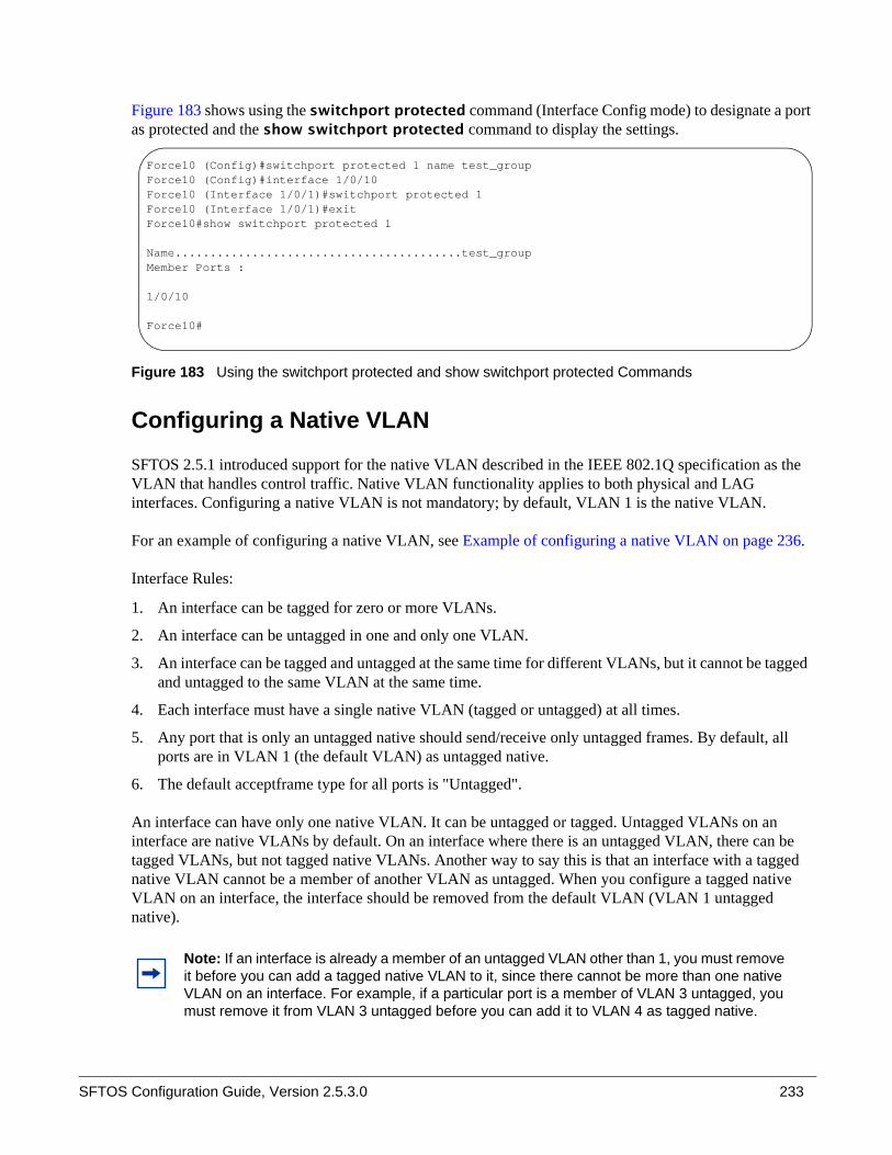
SFTOS Configuration Guide, Version 2.5.3.0 233
Figure 183 shows using the switchport protected command (Interface Config mode) to designate a port as protected and the show switchport protected command to display the settings.
Figure 183 Using the switchport protected and show switchport protected Commands
Configuring a Native VLAN
SFTOS 2.5.1 introduced support for the native VLAN described in the IEEE 802.1Q specification as the VLAN that handles control traffic. Native VLAN functionality applies to both physical and LAG interfaces. Configuring a native VLAN is not mandatory; by default, VLAN 1 is the native VLAN.
For an example of configuring a native VLAN, see Example of configuring a native VLAN on page 236.
Interface Rules:
1. An interface can be tagged for zero or more VLANs.
2. An interface can be untagged in one and only one VLAN.
3. An interface can be tagged and untagged at the same time for different VLANs, but it cannot be tagged and untagged to the same VLAN at the same time.
4. Each interface must have a single native VLAN (tagged or untagged) at all times.
5. Any port that is only an untagged native should send/receive only untagged frames. By default, all ports are in VLAN 1 (the default VLAN) as untagged native.
6. The default acceptframe type for all ports is "Untagged".
An interface can have only one native VLAN. It can be untagged or tagged. Untagged VLANs on an interface are native VLANs by default. On an interface where there is an untagged VLAN, there can be tagged VLANs, but not tagged native VLANs. Another way to say this is that an interface with a tagged native VLAN cannot be a member of another VLAN as untagged. When you configure a tagged native VLAN on an interface, the interface should be removed from the default VLAN (VLAN 1 untagged native).
Note: If an interface is already a member of an untagged VLAN other than 1, you must remove it before you can add a tagged native VLAN to it, since there cannot be more than one native VLAN on an interface. For example, if a particular port is a member of VLAN 3 untagged, you must remove it from VLAN 3 untagged before you can add it to VLAN 4 as tagged native.
Force10 (Config)#switchport protected 1 name test_groupForce10 (Config)#interface 1/0/10Force10 (Interface 1/0/1)#switchport protected 1Force10 (Interface 1/0/1)#exitForce10#show switchport protected 1
Name.........................................test_groupMember Ports :
1/0/10
Force10#

234
Two commands can configure a native VLAN:
• tagged interface-range native (The selected VLAN is supported as native by these tagged ports.)• untagged interface-range (These ports participate as untagged in the selected VLAN, which is the
native VLAN.)
Whichever is configured first will be allowed for the interface, and subsequent requests for the native VLAN will be rejected (First use the no form of the command to remove the participation.)
If the interface is untagged for one VLAN, it cannot be untagged for any other VLAN, and this is the native VLAN for the interface (only one native VLAN per port).
By default, VLAN 1 is the native VLAN. Until another VLAN is configured to be the native VLAN, VLAN 1 will be the native VLAN and cannot be removed.
Two commands can unconfigure the native VLAN configuration:
• no tagged interface native (VLAN 1 is added to the interface as the native VLAN. The equivalent of a vlan acceptframe all setting is added for the interface.)
• no untagged interface (VLAN 1 is added to the interface as the native VLAN.)
When using the tagged interface-range native command, the system applies the following checks before allowing the configuration (a tagged VLAN and an untagged VLAN cannot coexist on one port):
Figure 184 Validating a Tagged Interface Supporting a Native VLAN
Is port 1/0/2 tagged as native for another VLAN?
Is port 1/0/2 untagged for another non-default VLAN?
No
YesReject command
Reject commandYes
tagged 1/0/2 native
Switch applies command, removes VLAN 1 as native VLAN, and configures frametype to "VLAN Only".
No

SFTOS Configuration Guide, Version 2.5.3.0 235
When using the untagged interface-range command, the system applies the following checks before allowing the configuration:
Figure 185 Validating an Untagged Interface
Is port 1/0/2 tagged as native for any other VLAN?
Is port 1/0/2 untagged for any other non-default VLAN?
No
YesReject command
Reject commandYes
untagged 1/0/2
Apply command; remove VLAN 1 as native VLAN.No
Is interface 1/0/2 tagged in some other VLAN?
Yes
Set frametype to admitall
Set frametype to UntaggedOnly

236
Figure 186 Validating a Tagged Interface
Example of configuring a native VLAN
Figure 187 Configuring Native VLAN
tagged 1/0/3
Is 1/0/3 untagged in the same VLAN? Reject command
Is 1/0/3 tagged native in the same VLAN?
Yes
No
Apply command; set acceptframe to admitall
No action required. If the interface is already tagged native, then acceptframe is already set to vlanonly, and
tagging properties are correct.
No
Yes
Force10 #configForce10 (Config)#interface vlan 10Force10 (Conf-if-vl-10)#tagged 1/0/1 nativeForce10 (Conf-if-vl-10)#untagged 1/0/2Force10 (Conf-if-vl-10)#exitForce10 (Config)#interface vlan 11Force10 (Conf-if-vl-11)#tagged 1/0/1 native Force10 (Conf-if-vl-11)#tagged 1/0/2 native Force10 (Conf-if-vl-11)#tagged 1/0/1Force10 (Conf-if-vl-11)#exit
commands rejected
in native VLAN 10; tagged VLAN 10, 11
native VLAN 10: 1//0/1, 1/0/2

SFTOS Configuration Guide, Version 2.5.3.0 237
.
Figure 188 Unconfiguring Native VLAN
Note the use of the caret (^) to indicate the native VLAN for a port: .
Figure 189 Using show vlan Command to Display Native VLAN Members
.
Figure 190 Using show interface Command to Display Native VLAN Membership
Force10 #configForce10 (Config)#interface vlan 10Force10 (Conf-if-vl-10)#no tagged 1/0/1 nativeForce10 (Conf-if-vl-10)#no untagged 1/0/2Force10 (Conf-if-vl-10)#exit
1/0/1 now in native VLAN 1; tagged in VLAN 111/0/2 now in native VLAN 1; tagged in VLAN 11
Force10 #show vlan
Codes: * - Default VLAN, G - GVRP VLANs, E - Ethernet interface, ^ - Native VLAN
Vlan Id Status Q Ports ------- --------- - --------* 1 Inactive U E ^1/0/1 , ^1/0/2 ,1/0/3 ,1/0/4 ,1/0/5 ,1/0/6 ,1/0/7 1/0/8 ,1/0/9 ,1/0/10,1/0/11,1/0/12,1/0/13,1/0/14 1/0/15,1/0/16,1/0/17,1/0/18,1/0/19,1/0/20,1/0/21 1/0/22,1/0/23,1/0/24,1/0/25,1/0/26,1/0/27,1/0/28 1/0/29,1/0/30,1/0/31,1/0/32,1/0/33,1/0/34,1/0/35 1/0/36,1/0/37,1/0/38,1/0/39,1/0/40,1/0/41,1/0/42 1/0/43,1/0/44,1/0/45,1/0/46,1/0/47,1/0/48,1/0/49 1/0/50
2 Inactive T E ^1/0/3
3 Inactive
Force10 #show interface 1/0/1
Packets Received Without Error................. 8Packets Received With Error.................... 0Broadcast Packets Received..................... 0Packets Transmitted Without Errors............. 0Transmit Packet Errors......................... 0Collision Frames............................... 0Time Since Counters Last Cleared............... 0 day 0 hr 19 min 22 secNative Vlan………………………… 1

238
Figure 191 Using show interface ethernet Command to Display Native VLAN Membership and Activity
Configuring a VLAN Tunnel (DVLAN or VLAN-Stack)
VLAN stacking, also called Double VLAN (DVLAN) and QinQ, support VLAN tunneling. In more detail, with the VLAN-Stack feature, you can “stack” VLANs into one tunnel and switch them through the network. This feature is a way to pass VLAN traffic from one customer domain to another through a metro core in a simple, cost-effective manner.
The additional tag on the traffic helps differentiate between customers in the MAN while preserving the VLAN identification of the individual customers when the traffic enters their own 802.1Q domains. The 4-byte tag precedes the VLAN tag and carries:
• Protocol ID (Ethertype field)• Customer ID (VLAN ID field)
DVLAN Tagging Considerations• Frame size: If the port is enabled for DVLAN tagging and maximum length frames are expected,
jumbo frame support should also be enabled (Use the mtu command in Interface Config mode).• Port types: DVLAN tagging may be enabled for a LAG, but not for LAG members, VLAN routing
ports, or probe ports.• Control frames: Control frames (e.g. GARP, LACPDUs) will be double-tagged.• Ethertypes for DVLAN tags (“DVLAN tag” is sometimes shortened to DVT):
• 802.1Q tag (0x8100)• vMAN tag (0x88A8)• Custom tag (any valid value)
Note: VLAN stacking functionality existed in SFTOS prior to SFTOS 2.5.2.0, but it was not tested in SFTOS 2.5.2.0, so it is not supported in versions after SFTOS 2.5.1.13.
Force10 #show interface ethernet 1/0/1Type................. NormalAdmin Mode........... Disable Physical Mode........ Auto Physical Status...... Down Speed................ 0 - None Duplex............... N/A Link Status.......... Down MAC Address.......... 0001.E8D5.A0DANative Vlan………………………… 1
Total Packets Received (Octets)................ 512 Packets Received > 1522 Octets................. 0 Packets RX and TX 64 Octets.................... 8 Packets RX and TX 65-127 Octets................ 0 Packets RX and TX 128-255 Octets............... 0 !--output truncated--!

SFTOS Configuration Guide, Version 2.5.3.0 239
• The tunnel port (core port; uplink port) cannot be a routed port.• After the outer tag is added, QoS on the inner tag is not supported.
DVLAN Configuration Sequence
If you have created the required VLANs and you want to associate access and trunk ports with a particular DVLAN bridging instance, you must enable the system for double VLAN tagging, define the access and trunk ports, and then enable tagging on the trunk (core) port.
STP BPDU tunneling: The l2pdu-forwarding mode, used for BPDU tunneling, is enabled by default. Use no dvlan-tunnel l2pdu-forwarding enable to disable forwarding. The default forwarding MAC address is 01:01:E8:00:00:00. Use dvlan-tunnel l2pdu-forwarding mac-address mac-addr to change the MAC address. Inspect settings with show dvlan-tunnel l2pdu-forwarding, as shown in Figure 192.
Figure 192 Example of Use of show dvlan-tunnel l2pdu-forwarding Command
Step Command Syntax Command Mode Purpose
1 dvlan-tunnel ethertype {802.1Q | vman | custom 0-65535}
Global Config Enables the system for double VLAN tagging with selected tagging.
2 interface unit/slot/port Global Config By default, all ports become trunk (core) ports. Select a port to configure as an access port.
3 mode dvlan-tunnel (same as mode dot1q-tunnel)
Interface Config Enable DVLAN tagging for the port.
4 show dvlan-tunnel
(same as show dot1q-tunnel)Privileged Exec Display DVLAN-enabled VLAN tagging.
5 show dvlan-tunnel interface {unit/slot/port | all}
(same as show dot1q-tunnel interface {unit/slot/port | all})
Privileged Exec Display detailed information for a specific interface.
Force10 S50 #show dvlan-tunnel l2pdu-forwarding
L2Pdu-Forwarding Mode: enabled.L2Pdu-Forwarding Mac: 01:01:E8:00:00:00

240
DVLAN configuration example
The example here shows how to configure VLANs so that VLAN traffic from switches R4 and R5 is encapsulated in frames tagged with VLAN 3 going through switch R7.
Figure 193 DVLAN Example Topology
Configure switch R4:
Figure 194 VLAN-Stack Configuration Sequence on R4
R4 (Config)#dvlan-tunnel ethertype vman
!---------Access port:-----------!R4 (Config)#interface 1/0/2R4 (Interface 1/0/2)#no shutdownR4 (Interface 1/0/2)#mode dvlan-tunnelR4 (Interface 1/0/2)#exit
!---------Trunk port:----------!R4 (Config)#interface 1/0/3R4 (Interface 1/0/3)#no shutdownR4 (Interface 1/0/3)#mode dvlan-tunnelR4 (Interface 1/0/3)#exit
!--------Trunked VLAN----------!R4 (Config)#interface vlan 3R4 (Conf-if-vl-3)#tagged 1/0/3R4 (Conf-if-vl-3)#untagged 1/0/2R4 (Conf-if-vl-3)#exit
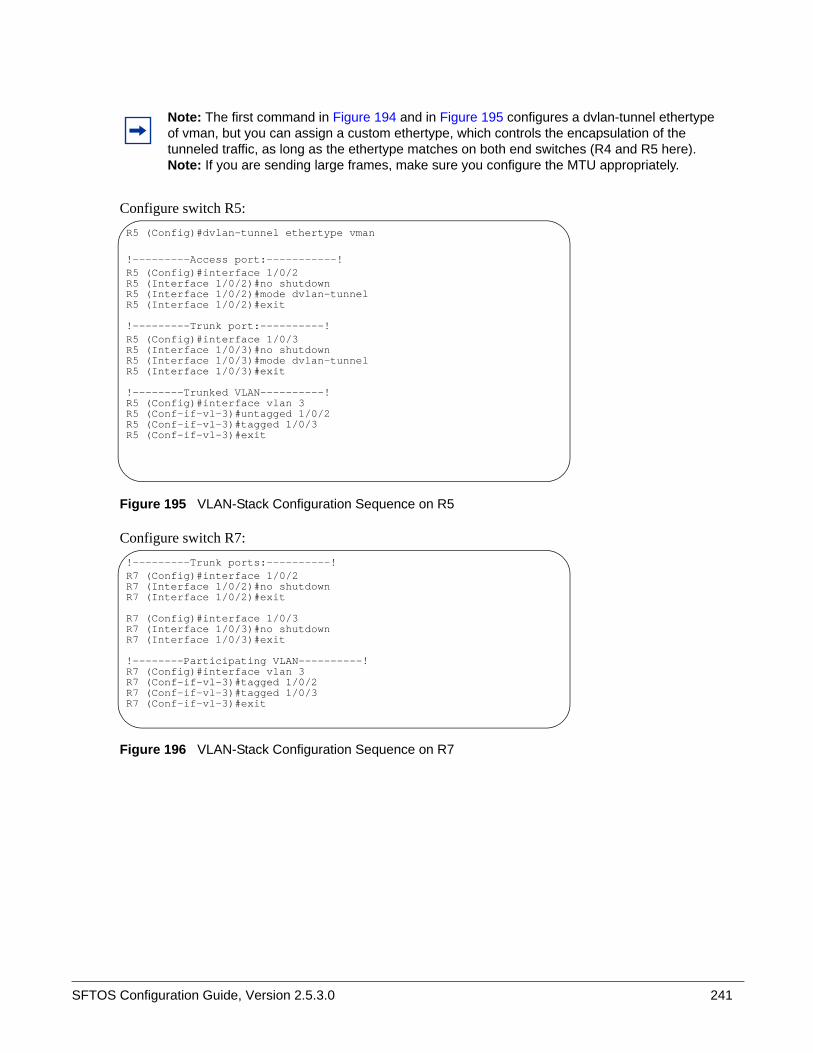
SFTOS Configuration Guide, Version 2.5.3.0 241
Configure switch R5:
Figure 195 VLAN-Stack Configuration Sequence on R5
Configure switch R7:
Figure 196 VLAN-Stack Configuration Sequence on R7
Note: The first command in Figure 194 and in Figure 195 configures a dvlan-tunnel ethertype of vman, but you can assign a custom ethertype, which controls the encapsulation of the tunneled traffic, as long as the ethertype matches on both end switches (R4 and R5 here).Note: If you are sending large frames, make sure you configure the MTU appropriately.
R5 (Config)#dvlan-tunnel ethertype vman
!---------Access port:-----------!R5 (Config)#interface 1/0/2R5 (Interface 1/0/2)#no shutdownR5 (Interface 1/0/2)#mode dvlan-tunnelR5 (Interface 1/0/2)#exit
!---------Trunk port:----------!R5 (Config)#interface 1/0/3R5 (Interface 1/0/3)#no shutdownR5 (Interface 1/0/3)#mode dvlan-tunnelR5 (Interface 1/0/3)#exit
!--------Trunked VLAN----------!R5 (Config)#interface vlan 3R5 (Conf-if-vl-3)#untagged 1/0/2R5 (Conf-if-vl-3)#tagged 1/0/3R5 (Conf-if-vl-3)#exit
!---------Trunk ports:----------!R7 (Config)#interface 1/0/2R7 (Interface 1/0/2)#no shutdownR7 (Interface 1/0/2)#exit
R7 (Config)#interface 1/0/3R7 (Interface 1/0/3)#no shutdownR7 (Interface 1/0/3)#exit
!--------Participating VLAN----------!R7 (Config)#interface vlan 3R7 (Conf-if-vl-3)#tagged 1/0/2R7 (Conf-if-vl-3)#tagged 1/0/3R7 (Conf-if-vl-3)#exit

242
Displaying VLAN InformationThe show port, show running-config (see Figure 197, below), and show vlan commands provide most of the information about the VLAN configuration. The show vlan command has the following options:
• (no option entered) Display summary information for all configured VLANs. See Figure 198, below.• association Display associations to VLANs. • brief Display switch VLANs.• id Display VLAN configuration and configure VLANs. See Figure 199, below.• name Display VLAN configuration for a VLAN with optional name.• port Display 802.1Q port parameters. See Figure 200, below.
See also the show commands exemplified above:
• Using show vlan Command to Display Native VLAN Members on page 237• Using show interface Command to Display Native VLAN Membership on page 237• Using show interface ethernet Command to Display Native VLAN Membership and Activity on
page 238
Use the following commands to display VLAN status and activity. For details, see Viewing Interface Information on page 120 and the System Management Commands chapter of the SFTOS Command Reference:
• show interface ethernet {switchport | unit/slot/port | 1-3965}: Each parameter yields different VLAN-related information.
• show interface {unit/slot/port | ethernet {switchport | unit/slot/port | 1-3965} | loopback | managementethernet | port-channel {1-128 | brief} | switchport}
• show mac-addr-table vlan VLAN_ID: This command reports the MAC addresses in the specified VLAN.

SFTOS Configuration Guide, Version 2.5.3.0 243
Figure 197 shows the use of the commands show running-config and show vlan brief to display VLAN settings. Note in the show vlan brief output that VLAN 1 exists even though it was not configured (VLAN 1 is the default VLAN, and all interfaces are members of VLAN 1 by default.):
Figure 197 Using the show running-config and show vlan brief Commands
Use the show vlan command, without parameters, to view the system VLAN configuration:
Figure 198 Example Output from show vlan Command
Note the use of the caret (^) in Figure 198 to indicate the native VLAN for a port.
Force10 #show running-config!Current Configuration:![excerpt showing just the vlan elements in the report]!
interface vlan 1exitinterface vlan 2exitinterface vlan 3exitForce10 #show vlan brief
VLAN Name STG MAC Aging IP Address--------- ---------- -------- ---------------- ---------------1 abc 0 1800 unassigned2 egf 0 1800 unassigned3 sss 0 1800 unassigned
Force10#show vlan
Codes: * - Default VLAN, G - GVRP VLANs, E - Ethernet interface, ^ - Native VLAN
Vlan Id Status Q Ports ------- --------- - --------* 1 Inactive U E 1/0/1 ,1/0/2 ,1/0/3 ,1/0/4 ,1/0/5 ,1/0/6 ,1/0/7 1/0/8 ,1/0/9 ,1/0/10,1/0/11,1/0/12,1/0/13,1/0/14 1/0/15,1/0/16,1/0/17,1/0/18,1/0/19,1/0/20,1/0/21 1/0/22,1/0/23,1/0/24,1/0/25,1/0/26,1/0/27,1/0/28 1/0/29,1/0/30,1/0/31,1/0/32,1/0/33,1/0/34,1/0/35 1/0/36,1/0/37,1/0/38,1/0/39,1/0/40,1/0/41,1/0/42 1/0/43,1/0/44,1/0/45,1/0/46,1/0/47,1/0/48,1/0/49 1/0/50,2/0/1 ,2/0/2 ,2/0/3 ,2/0/4 ,2/0/5 ,2/0/6 2/0/7 ,2/0/8 ,2/0/9 ,2/0/10,2/0/11,2/0/12,2/0/13 2/0/14,2/0/15,2/0/16,2/0/17,2/0/18,2/0/19,2/0/20 2/0/21,2/0/22,2/0/23,2/0/24,2/0/25,2/0/26,2/0/27 2/0/28,2/0/29,2/0/30,2/0/31,2/0/32,2/0/33,2/0/34 2/0/35,2/0/36,2/0/37,2/0/38,2/0/39,2/0/40,2/0/41 2/0/42,2/0/43,2/0/44,2/0/45,2/0/46,2/0/47,2/0/48 2/0/49,2/0/50,3/0/1 ,3/0/2 ,3/0/3 ,3/0/4 ,3/0/5 3/0/6 ,3/0/7 ,3/0/8 ,3/0/9 ,3/0/10,3/0/11,3/0/12 3/0/13,3/0/14,3/0/15,3/0/16,3/0/17,3/0/18,3/0/19 3/0/20,3/0/21,3/0/22,3/0/23,3/0/24,3/0/25,3/0/262 Inactive T E ^1/0/3
3 Inactive!

244
Using the show vlan id vlan-id command command, used here to display one VLAN comprised of a port (first display) and then another VLAN comprised of a LAG :
Figure 199 Example Output from show vlan id Command
Use the show vlan port command, with an interface or all parameter, to learn the association between individual ports and VLANs:
Figure 200 Example Output from show vlan Command
Force10#show vlan id 1Codes: * - Default VLAN, G - GVRP VLANs, E - Ethernet interface, ^ - Native VLAN
Vlan Id Status Q Ports--------- ---------- - ------2 Inactive T E ^1/0/3
R2 #show vlan id 300
Codes: * - Default VLAN, G - GVRP VLANs, E - Ethernet interface
Vlan Id Status Q Ports ------- --------- - -------- 300 Active T Po1
Force10-S50 #show vlan port 1/0/1 Port Acceptable Ingress DefaultInterface VLAN ID Frame Types Filtering GVRP Priority--------- ------- ------------ ----------- ------- --------1/0/1 1 Admit All Enable Disable 0
Protected Port .............................. False
Force10-S50 #show vlan port all Port Acceptable Ingress DefaultInterface VLAN ID Frame Types Filtering GVRP Priority--------- ------- ------------ ----------- ------- --------1/0/1 1 Admit All Enable Disable 0 1/0/2 1 Admit All Enable Disable 0 1/0/3 1 Admit All Enable Disable 0 1/0/4 1 Admit All Enable Disable 0 1/0/5 1 Admit All Enable Disable 0 1/0/6 1 Admit All Enable Disable 0 1/0/7 1 Admit All Enable Disable 0 1/0/8 1 Admit All Enable Disable 0 1/0/9 1 Admit All Enable Disable 0 1/0/10 1 Admit All Enable Disable 0 !----output truncated--------!

SFTOS Configuration Guide, Version 2.5.3.0 245
This chapter discusses the use of IGMP (Internet Group Management Protocol) commands for IGMP Snooping, in the following major sections:
• Enabling IGMP Snooping on page 245• Monitoring IGMP Snooping on page 246
See also IGMP Proxy on page 259 in the Routing chapter of this guide.
IGMP in SFTOS:
• Uses Version 3 of IGMP• Includes IGMP Snooping that can be enabled per VLAN
Typically, a switch employing IGMP forwards multicast packets out all ports in a VLAN until it receives an IGMP membership report. The IGMP Snooping feature enables the switch to monitor IGMP transactions between hosts and routers. It can help to conserve bandwidth by allowing the switch to forward IP multicast traffic only to connected hosts that request multicast traffic.
Enabling IGMP Snooping 1. From Global Config mode, enable IGMP Snooping on the switch:
igmp enable (in SFTOS Version 2.2, use set igmp)
2. From Interface VLAN mode, enable IGMP Snooping on the selected VLAN:
igmp enable (in SFTOS Version 2.2, use set igmp vlanid in VLAN database mode)
3. Enable IGMP Snooping on all interfaces:
igmp interfacemode enable all (in SFTOS Version 2.2, use set igmp interfacemode)
4. Commands to configure timers:
set igmp groupmembership-interval 2-3600
— Default 125 seconds
Chapter 14 IGMP Snooping
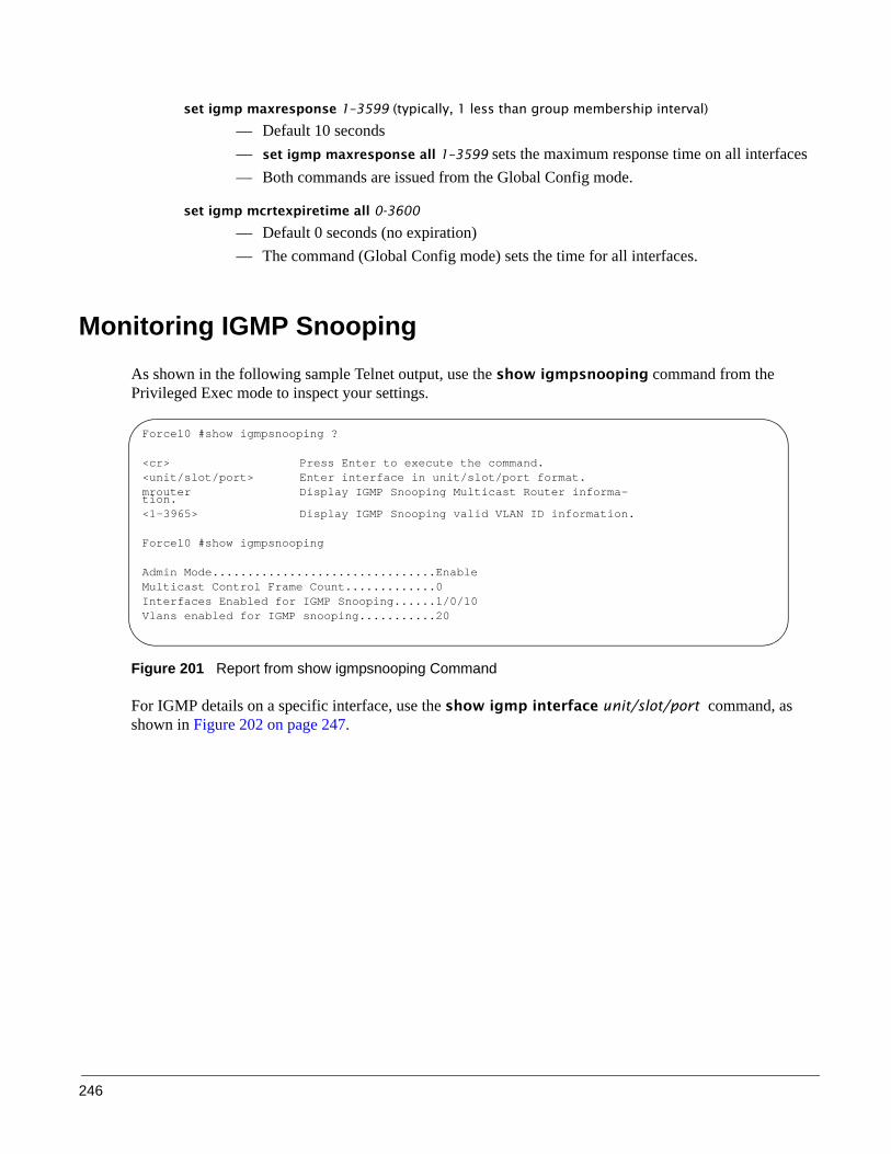
246
set igmp maxresponse 1–3599 (typically, 1 less than group membership interval)
— Default 10 seconds— set igmp maxresponse all 1–3599 sets the maximum response time on all interfaces— Both commands are issued from the Global Config mode.
set igmp mcrtexpiretime all 0-3600
— Default 0 seconds (no expiration)— The command (Global Config mode) sets the time for all interfaces.
Monitoring IGMP Snooping As shown in the following sample Telnet output, use the show igmpsnooping command from the Privileged Exec mode to inspect your settings.
Figure 201 Report from show igmpsnooping Command
For IGMP details on a specific interface, use the show igmp interface unit/slot/port command, as shown in Figure 202 on page 247.
Force10 #show igmpsnooping ?
<cr> Press Enter to execute the command.<unit/slot/port> Enter interface in unit/slot/port format.mrouter Display IGMP Snooping Multicast Router informa-tion.<1-3965> Display IGMP Snooping valid VLAN ID information.
Force10 #show igmpsnooping
Admin Mode................................EnableMulticast Control Frame Count.............0Interfaces Enabled for IGMP Snooping......1/0/10Vlans enabled for IGMP snooping...........20

SFTOS Configuration Guide, Version 2.5.3.0 247
Figure 202 Report from show igmp interface Command
Use the show mac-address-table igmpsnooping command to display the IGMP Snooping entries in the Multicast Forwarding Database (MFDB) table.
Figure 203 Report from show mac-address-table igmpsnooping Command
Force10 #show igmp interface ?
<unit/slot/port> Enter interface in unit/slot/port format.membership Display interfaces subscribed to the multicast group.stats Display IGMP statistical information.
Force10 #show igmp interface 1/0/10
Slot/Port......................................1/0/10IGMP Admin Mode................................EnableInterface Mode.................................DisableIGMP Version...................................3Query Interval (secs)..........................125Query Max Response Time (1/10 of a second......100Robustness.....................................2Startup Query Interval (secs)..................31Startup Query Count............................2Last Member Query Interval (1/10 of a second)..10Last Member Query Count........................2
Force10 #show mac-address-table igmpsnooping
MAC Address Type Description Interfaces----------------------- ------- -------------- -----------00:01:01:00:5E:00:01:16 Dynamic Network Assist Fwd: 1/0/4700:01:01:00:5E:00:01:18 Dynamic Network Assist Fwd: 1/0/4700:01:01:00:5E:37:96:D0 Dynamic Network Assist Fwd: 1/0/4700:01:01:00:5E:7F:FF:FA Dynamic Network Assist Fwd: 1/0/4700:01:01:00:5E:7F:FF:FE Dynamic Network Assist Fwd: 1/0/47

248
Use the show ip igmp interface unit/slot/port command to display IGMP details for a particular interface.
Figure 204 Report from show ip igmp interface Command
Use the show mac-address-table igmpsnooping command to display the IGMP Snooping entries in the Multicast Forwarding Database (MFDB) table.
Figure 205 Report from show mac-address-table igmpsnooping Command
Use the show mac-address-table igmpsnooping command to display the IGMP Snooping entries in the Multicast Forwarding Database (MFDB) table.
Figure 206 Report from show mac-address-table igmpsnooping Command
Force10 #show ip igmp ?<cr> Press Enter to execute the command.groups Display the subscribed multicast groups.interface Display IGMP configuration information.
Force10 #show ip igmp interface 1/0/2
Slot/Port.......................................1/0/2IGMP Admin Mode.................................EnableInterface Mode..................................DisableIGMP Version....................................3Query Interval (secs)...........................125Query Max Response Time (1/10 of a second)......100Robustness......................................2Startup Query Interval (secs)...................31Startup Query Count.............................2Last Member Query Interval (1/10 of a second)...10
Force10 #show mac-address-table igmpsnooping
MAC Address Type Description Interfaces----------------------- ------- -------------- -----------00:01:01:00:5E:00:01:16 Dynamic Network Assist Fwd: 1/0/4700:01:01:00:5E:00:01:18 Dynamic Network Assist Fwd: 1/0/4700:01:01:00:5E:37:96:D0 Dynamic Network Assist Fwd: 1/0/4700:01:01:00:5E:7F:FF:FA Dynamic Network Assist Fwd: 1/0/4700:01:01:00:5E:7F:FF:FE Dynamic Network Assist Fwd: 1/0/47

SFTOS Configuration Guide, Version 2.5.3.0 249
This chapter contains the following sections:
• Port Mirroring Features• Port Mirroring Commands on page 250• Port Mirroring Configuration Examples on page 250• Verifying Port Mirroring on page 252
Port Mirroring Features• Enables you to monitor network traffic with an external network analyzer• Forwards a copy of each incoming and outgoing packet to a specific port that you designate• Is used as a diagnostic tool, debugging feature, or means of fending off attacks• The mirrored port (also called a source port) can be a part of any VLAN, whereas the destination port
(also called a probe port or mirroring port) cannot be a VLAN member.• In an S-Series stack, the mirrored port and destination port can be on separate stack members. • A stack has a limit of one port mirroring session and one destination port. More than one mirrored port
can be designated, but the percentage of the source traffic accepted on the probe port is likely to decline with each added source, depending on the amount of traffic — to roughly 50% each for two source ports, 33% per port for three, and so on.
Inbound or outbound packets will switch to their destination and will be copied to the mirrored port.
Figure 207 Port Mirroring Diagram
Chapter 15 Port Mirroring
Mirrored Port
Portssendingdata tomirroredport
Ports data frommirrored
Probe PortSwitch
receiving
port

250
Port Mirroring CommandsThe following are common port mirroring commands using Figure 207 as a model:
• Enable port mirroring session (default is disable):monitor session 1 mode
• Configure mirrored port:monitor session 1 source interface 1/0/2
• Configure destination port/probe port:monitor session 1 destination interface 1/0/3 (Remove an existing destination port before replacing it with another.)
• Disable monitor session mode before revising probe and mirrored port configuration:no monitor session 1 mode
• Unconfigure mirrored port:no monitor session 1 source interface 1/0/2
• Unconfigure probe port before configuring another probe port:no monitor session 1 destination 1/0/3
• Disable port mirroring:no monitor
For details on port mirroring command syntax, see the System Configuration chapter of the SFTOS Command Reference.
Port Mirroring Configuration ExamplesThe following are port mirroring configuration examples:
Preparing to Configure Port Mirroring
Typically, before configuring mirroring sessions, you would inspect existing conditions.
Use the show monitor session 1command to display the session—ID, admin mode, probe port, and mirrored port:
Figure 208 Using the show monitor session command
Force10 #show monitor session 1
Session ID Admin Mode Probe Port Mirrored Port---------- ---------- ---------- -------------1 Enable 1/0/5 1/0/4

SFTOS Configuration Guide, Version 2.5.3.0 251
Configuring the mirrored port and destination port
When enabled, the probe port monitors all traffic received and transmitted on the monitored port.
A session is operationally active if and only if both a destination port and at least one source port is configured. If neither is true, the session is inactive.
A port configured as a destination port acts as a mirroring port when the session is operationally active. If it is not, the port acts as a normal port and participates in all normal operation with respect to transmitting traffic.
1. Specify the source and destination mirror ports:
Figure 209 Example of Specifying Source and Destination Mirror Ports
2. Enable port security from the Interface Config mode for the specific interface. Access the mode with the command interface unit/slot/port. Then use the port-security command, as shown in Figure 210.
Figure 210 Example of Enabling Port Security
Starting a mirroring session
Figure 211 Command Example: Starting a Port Mirroring Session
Force10 (Config) #monitor session 1 source interface 1/0/4Force10 (Config) #monitor session 1 destination interface 1/0/5
Force10 (Interface 1/0/4) #port-security ?
<cr> Press Enter to execute the command.mac-address Add Static MAC address to the interface.max-dynamic Set Dynamic Limit for the interface.max-static Set Static Limit for the interface.
Force10 (Config)(Interface 1/0/4)#port-security max-static ?
<0-20> Set Static Limit for the interface.
Force10 (Interface 1/0/4)#port-security max-static 5Force10 (Interface 1/0/4)#port-security max-dynamic 10
Force10 (Config)#monitor session 1 mode

252
Stopping the mirroring session and removing probe and mirrored ports
Figure 212 Command Examples: Removing port mirroring configuration
Verifying Port MirroringUse the following commands from the Privileged Exec mode to inspect port mirroring settings:
• show monitor session 1: See Figure 213• show port all: See Figure 213• show running-config: See Figure 215• show port: See Figure 216
Verifying port mirroring session status
Figure 213 show monitor session 1 Command Output
In Figure 213, note that the probe (destination) port and mirrored ports are in different stack members.
Note: Alternatively, you can use the no monitor command to disable port mirroring, which automatically removes the mirror and probe configuration from the source and destination ports. Then, reenabling port mirroring requires designating the source and destination ports again.
Force10 (Config)#no monitor session 1 modeForce10 (Config)#no monitor session sourceForce10 (Config)#no monitor session destination
Force10 #show monitor session 1
Session ID Admin Mode Probe Port Mirrored Port---------- ---------- ---------- -------------1 Enable 2/0/26 1/0/1
1/0/11

SFTOS Configuration Guide, Version 2.5.3.0 253
Using other commands that show port mirroring status
You can use the show port all command to show all existing probe ports and mirrored ports, along with their operational status:
Figure 214 Example of show port all Showing Port Mirroring
Figure 215 Using show running-config Command Output to Show Port Mirroring
Also, you can use the show port interface command for information on whether a specific port is the mirror or probe port and what is enabled or disabled on it.
Figure 216 Using the show port command
Force10 S50 #show port all
Admin Physical Physical Link Link LACPInterface Type Mode Mode Status Status Trap Mode---------- ------ ------- ---------- ---------- ------ ------- -------1/0/1 Mirror Enable Auto 100 Full Up Enable Enable1/0/2 Disable Auto Down Enable Enable2/0/24 Disable Auto Down Enable Enable2/0/25 Disable Auto Down Enable Enable2/0/26 Probe Enable Auto 1000 Full Up Enable Enable2/0/27 Disable Auto Down Enable Enable2/0/28 Disable Auto Down Enable Enable
Force10 S50 #show running-config!---------<snip>---------------!monitor session 1 destination interface 2/0/26monitor session 1 source interface 1/0/1monitor session 1 mode
Force10 #show port 1/0/4Admin Physical Physical Link Link LACP
Intf Type Mode Mode Status Status Trap Mode---- ---- ------ -------- -------- ------ ---- ----1/0/4 Mirror Enable Auto Down Enable Enable
Force10 #show port 1/0/5Admin Physical Physical Link Link LACP
Intf Type Mode Mode Status Status Trap Mode---- ---- ------ -------- -------- ------ ---- ----1/0/5 Probe Enable Auto Down Enable Enable

254

SFTOS Configuration Guide, Version 2.5.3.0 255
This chapter contains these major sections:• Enabling Routing on page 256• IGMP Proxy on page 259• RIP Configuration on page 263• OSPF Configuration on page 265• VLAN Routing on page 270• Link Aggregation on page 277• Virtual Router Redundancy Protocol on page 279
This chapter provides examples of how to use the routing features provided in the SFTOS Layer 3 Package (available only for some S-Series models) to configure your S-Series in some typical network scenarios. The examples begin with support for port routing in a simple network, and explain how to activate the most common routing protocols. A discussion of the use of VLANs with and without VLAN routing is followed by sections on Link Aggregation and Virtual Router Redundancy Protocol. For an introduction to the use of services related to Layer 3, such as Access Control Lists and Differentiated Services, see their specific chapters in this guide.
An end station specifies the destination station’s Layer 3 address in the packet’s IP header, but sends the packet to the MAC address of a router. When the Layer 3 router receives the packet, it will minimally:
• Look up the Layer 3 address in its address table to determine the outbound port • Update the Layer 3 header • Recreate the Layer 2 header The router’s IP address is often statically configured in the end station, although the S-Series supports protocols such as DHCP that allow the address to be assigned dynamically. Likewise, you may assign some of the entries in the routing tables used by the router statically, but protocols such as RIP and OSPF allow the tables to be created and updated dynamically as the network configuration changes.
Chapter 16 Layer 3 Routing
Note: ECMP (Equal Cost Multi-path Routing) is supported for OSPF, not for RIP. 2048 IP routes of the 3072 routes that are supported by SFTOS can be ECMP routes. 6 ECMP paths are supported. Load balancing is provided automatically by a hash algorithm that is based on an XOR (eXclusive OR) of the 3 LSBs (Least Significant Bits) of the source and destination IP addresses. Use the maximum-paths command to set the number of paths. For details, see the maximum-paths command in Chapter 20, “OSPF Commands”, of the SFTOS Command Reference Guide.

256
Enabling RoutingThe S-Series always provides Layer 2 bridging, while Layer 3 routing must be explicitly enabled, first for the S-Series router as a whole, and then for each port that is to participate in the routed network.
As introduced in the Getting Started chapter, use the show version command (see Figure 8 on page 43) to verify that the Routing package (“Layer 3 Package”) of SFTOS is installed in order to utilize these routing procedures.
Then, to inspect the system for configured Layer 3 interfaces, use the show ip interface brief command (see Figure 16 on page 49).
For more details about a specific interface, use the following commands (Note, however, that routing must be enabled before these commands produce a report.):
• show ip interface unit/slot/port: See Figure 15 on page 49.• show ip interface vlan vlan-ID
To view IP information on a Layer 3 interface, use the show ip interface command in the Privileged Exec mode (Figure 217).
Figure 217 show ip interface Command Example
The configuration commands used in the example in this section enable IP routing on ports 1/0/2, 1/0/3, and 1/0/5. The router ID will be set to the management IP address of the S50 stack, or to that of any active router interface if the management address is not configured.
After the routing configuration commands have been issued, the following functions will be active:
• IP Forwarding, responsible for forwarding received IP packets• ARP Mapping, responsible for maintaining the ARP Table used to correlate IP and MAC addresses.
The table contains both static entries and entries dynamically updated based on information in received ARP frames.
• Routing Table Object, responsible for maintaining the common routing table used by all registered routing protocols
Force10 >show ip int vlan 58Vlan 58 is up, line protocol is upInternet address is 1.1.49.1/24Broadcast address is 1.1.49.255Address determined by config fileMTU is 1554 bytesInbound access list is not setProxy ARP is enabledSplit Horizon is enabledPoison Reverse is disabledICMP redirects are not sentICMP unreachables are not sent

SFTOS Configuration Guide, Version 2.5.3.0 257
You may then activate RIP or OSPF, used by routers to exchange route information, on top of IP Routing. RIP is more often used in smaller networks, while OSPF was designed for larger and more complex topologies.
Then invoke the following commands, assuming that you are still in Interface Config mode after completing the Layer 2 procedure (see Configuring Physical Interfaces on page 125):
Step Command Syntax Command Mode Purpose
1 ip routing Config Enable routing on the switch.
2 interface unit/slot/port
Config To access the INTERFACE mode for the selected port, enter the keyword interface followed by the port number in unit/slot/port format. For example, to enable port 4 on stack member 2, enter interface 2/0/4.
3 ip address ip-addr mask
Interface Config Assign an IP address to the port to use for routing. Enter the key words ip address followed by the IP address and subnet mask in IPv4 format (A.B.C.D).
4 routing Interface Config Enable routing on the selected interface.
5 exit Interface Config Return to Global Config mode.
6 exit Global Config Access Privileged Exec mode.
7 show ip interface unit/slot/port
Privileged Exec Inspect the interface to verify the changed settings.
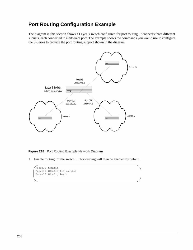
258
Port Routing Configuration Example
The diagram in this section shows a Layer 3 switch configured for port routing. It connects three different subnets, each connected to a different port. The example shows the commands you would use to configure the S-Series to provide the port routing support shown in the diagram.
Figure 218 Port Routing Example Network Diagram
1. Enable routing for the switch. IP forwarding will then be enabled by default.
Subnet 3
Subnet 5Subnet 2
Port 0/2192.150.2.2
Port 0/3192.130.3.1
Port 0/5192.64.4.1
Layer 3 Switchacting as a router
Force10 #configForce10 (Config)#ip routing Force10 (Config)#exit
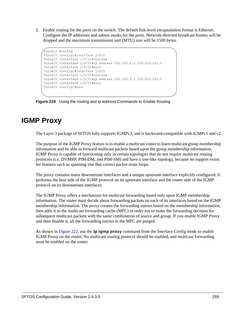
SFTOS Configuration Guide, Version 2.5.3.0 259
2. Enable routing for the ports on the switch. The default link-level encapsulation format is Ethernet. Configure the IP addresses and subnet masks for the ports. Network-directed broadcast frames will be dropped and the maximum transmission unit (MTU) size will be 1500 bytes.
Figure 219 Using the routing and ip address Commands to Enable Routing
IGMP Proxy The Layer 3 package of SFTOS fully supports IGMPv3, and is backward-compatible with IGMPv1 and v2.
The purpose of the IGMP Proxy feature is to enable a multicast router to learn multicast group membership information and be able to forward multicast packets based upon the group membership information. IGMP Proxy is capable of functioning only in certain topologies that do not require multicast routing protocols (i.e. DVMRP, PIM-DM, and PIM-SM) and have a tree-like topology, because no support exists for features such as spanning tree that correct packet route loops.
The proxy contains many downstream interfaces and a unique upstream interface explicitly configured. It performs the host side of the IGMP protocol on its upstream interface and the router side of the IGMP protocol on its downstream interfaces.
The IGMP Proxy offers a mechanism for multicast forwarding based only upon IGMP membership information. The router must decide about forwarding packets on each of its interfaces based on the IGMP membership information. The proxy creates the forwarding entries based on the membership information, then adds it to the multicast forwarding cache (MFC) in order not to make the forwarding decision for subsequent multicast packets with the same combination of source and group. If you enable IGMP Proxy and then disable it, all the forwarding entries in the MFC are purged.
As shown in Figure 222, use the ip igmp proxy command from the Interface Config mode to enable IGMP Proxy on the router. No multicast routing protocol should be enabled, and multicast forwarding must be enabled on the router.
Force10 #configForce10 (Config)#interface 1/0/2Force10 (Interface 1/0/2)#routingForce10 (Interface 1/0/2)#ip address 192.150.2.1 255.255.255.0Force10 (Interface 1/0/2)#exitForce10 (Config)#interface 1/0/5Force10 (Interface 1/0/5)#routingForce10 (Interface 1/0/5)#ip address 192.150.5.1 255.255.255.0Force10 (Interface 1/0/5)#exitForce10 (Config)#exit

260
IGMP Proxy ConfigurationThe following procedure shows the basic steps for creation and configuring of an IGMP Proxy router.
IGMP Proxy configuration example
The following example, as illustrated in Figure 220 on page 261, configures the S-Series switch identified as Unit 1, as the IGMP Proxy router, then configures port 1/0/48 as the IGMP Proxy port, and then configures VLAN 2 as the IGMP Proxy VLAN and to include port 1/0/48. First, IP routing, multicast forwarding, and IGMP must be enabled for the switch.
Step Command Syntax Command Mode Purpose
1 ip routing Global Config Enable routing on the switch.
2 ip multicast Global Config Enable multicast forwarding on the router.Note: No multicast routing protocols can be enabled on the router.
3 ip igmp Global Config Set the IGMP administrative mode to active in the router.
4 interface unit/slot/port Global Config Access the port that will forward IGMP Proxy control data.
5 no shutdown Interface Config Enable the selected port.
6 routing Interface Config Enable routing for the selected port.
7 ip address ip_address subnet_mask
Interface Config Assign an IP address and subnet mask to the selected port.
8 ip igmp-proxy Interface Config Designate the selected port as the IGMP Proxy port.
9 interface vlan vlan-id VLAN Create and/or access the designated VLAN.
10 untagged unit/slot/port VLAN Add the port configured earlier to the selected VLAN as untagged.
11 ip address ip_address subnet_mask
VLAN Assign an IP address and subnet mask to the selected VLAN.
12 ip igmp-proxy VLAN Set the administrative mode of IGMP for the selected VLAN to active.

SFTOS Configuration Guide, Version 2.5.3.0 261
Figure 220 IGMP Proxy Topology
Figure 221 Configuring an Interface to Enable IGMP Proxy
To set the report interval, use the ip igmp-proxy unsolicit-rprt-interval command:
Figure 222 Configuring an Interface to Enable IGMP Proxy
Force10 #configForce10 (Config)#ip routingForce10 (Config)#ip multicastForce10 (Config)#ip igmpForce10 (Config)#interface 1/0/48Force10 (Interface 1/0/48)# no shutdownForce10 (Interface 1/0/48)#routingForce10 (Interface 1/0/48)#ip address 4.4.4.4 255.255.255.0Force10 (Interface 1/0/48)#ip igmp-proxyForce10 (Interface 1/0/48)#exitForce10 (Config)#interface vlan 2Force10 (conf-if-vl-2)#ip address 4.4.4.4 255.255.255.0Force10 (conf-if-vl-2)#ip igmp-proxyForce10 (conf-if-vl-2)#untagged 1/0/48
Force10 #configForce10 (Config)#interface 1/0/15Force10 (Interface 1/0/15)#ip igmp-proxy ?<cr> Press Enter to execute the command.reset-status Reset All the proxy interface status parameters.unsolicited-report-interval Configure IGMP Proxy unsolicited report interval.
Force10 (Interface 1/0/1)#ip igmp-proxyForce10 (Interface 1/0/15)#ip igmp-proxy unsolicit-rprt-interval 260 Force10 (Interface 1/0/15)#exitForce10 (Config)#

262
Verifying the configuration
Verify the configuration with these show commands, in Privileged Exec or User Exec modes:
Use the show ip igmp-proxy command to display host interface status parameters. It displays operational parameters only when IGMP Proxy is enabled, as shown in Figure 224
Figure 223 Using the show ip igmp-proxy Command
• show ip igmp-proxy groups command: Figure 225• show ip igmp-proxy interface command: Figure 226
Other relevant show commands include:
• show ip igmp-proxy interface {unit/slot/port | vlan 1-3965}• show ip igmp-proxy groups {unit/slot/port [detail] | 1-3965 [detail]}• show ip igmp-proxy groups detail
Figure 224 Using the show ip igmp-proxy Command
Figure 225 Using the show ip igmp-proxy groups Command
Force10 #show ip igmp-proxyAdmin Mode..................................... EnableOperational Mode............................... Disable
Force10-S50V#show ip igmp-proxyVLAN .......................................... 2Admin Mode..................................... EnableOperational Mode............................... EnableVersion........................................ 3Number of Multicast Groups..................... 0Unsolicited Report Interval.................... 1Querier IP Address on Proxy Interface.......... 0.0.0.0Older Version 1 Querier Timeout................ 0Older Version 2 Querier Timeout................ 0Proxy Start Frequency.......................... 3
Force10-S50V#show ip igmp-proxy groups
VLAN .......................................... 2
Group Address Last Reporter Up Time Member State Filter Mode Sources--------------- --------------- ------- ------------ ----------- -------
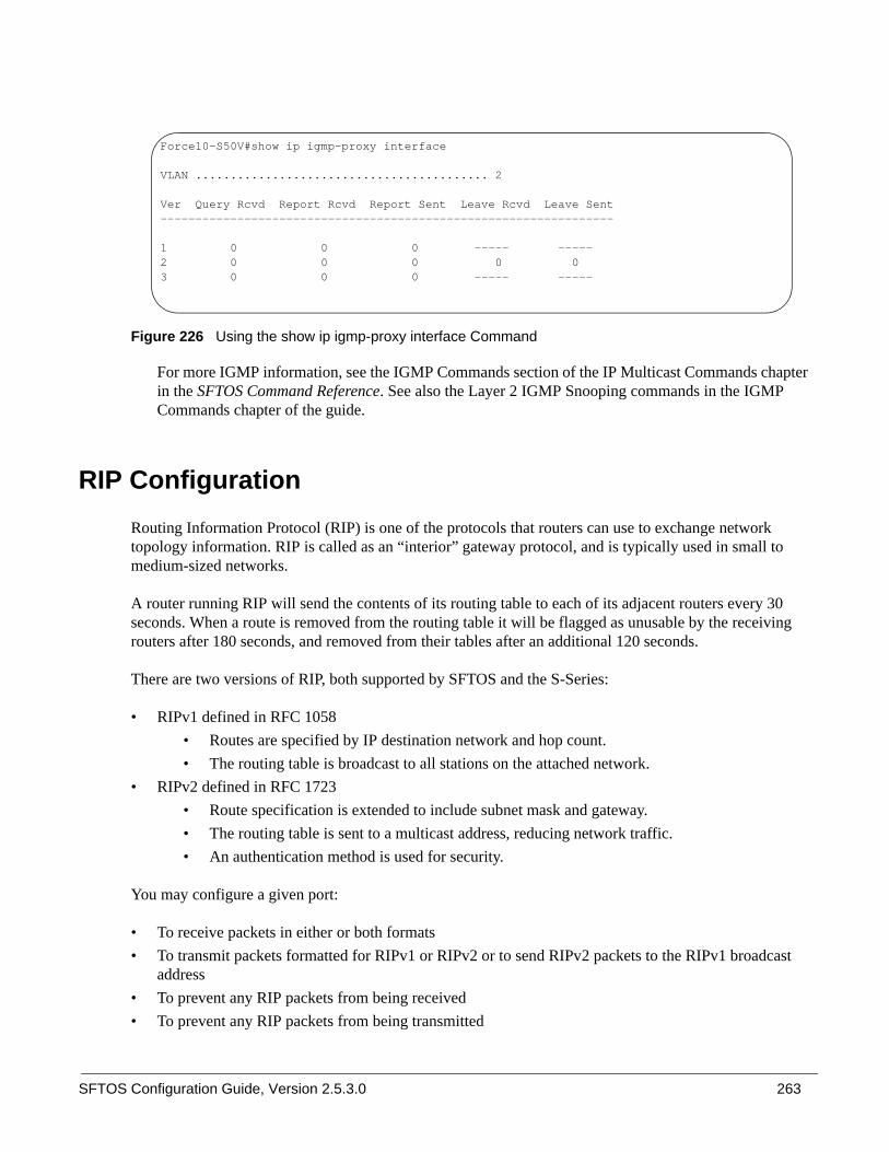
SFTOS Configuration Guide, Version 2.5.3.0 263
Figure 226 Using the show ip igmp-proxy interface Command
For more IGMP information, see the IGMP Commands section of the IP Multicast Commands chapter in the SFTOS Command Reference. See also the Layer 2 IGMP Snooping commands in the IGMP Commands chapter of the guide.
RIP ConfigurationRouting Information Protocol (RIP) is one of the protocols that routers can use to exchange network topology information. RIP is called as an “interior” gateway protocol, and is typically used in small to medium-sized networks.
A router running RIP will send the contents of its routing table to each of its adjacent routers every 30 seconds. When a route is removed from the routing table it will be flagged as unusable by the receiving routers after 180 seconds, and removed from their tables after an additional 120 seconds.
There are two versions of RIP, both supported by SFTOS and the S-Series:
• RIPv1 defined in RFC 1058 • Routes are specified by IP destination network and hop count.• The routing table is broadcast to all stations on the attached network.
• RIPv2 defined in RFC 1723• Route specification is extended to include subnet mask and gateway.• The routing table is sent to a multicast address, reducing network traffic.• An authentication method is used for security.
You may configure a given port:
• To receive packets in either or both formats • To transmit packets formatted for RIPv1 or RIPv2 or to send RIPv2 packets to the RIPv1 broadcast
address• To prevent any RIP packets from being received• To prevent any RIP packets from being transmitted
Force10-S50V#show ip igmp-proxy interface
VLAN .......................................... 2
Ver Query Rcvd Report Rcvd Report Sent Leave Rcvd Leave Sent-----------------------------------------------------------------
1 0 0 0 ----- -----2 0 0 0 0 03 0 0 0 ----- -----

264
RIP Configuration Example
The configuration commands used in the following example enable RIP on ports 1/0/2 and 1/0/3:
1. Enable routing for the switch.
Figure 227 Using the ip routing Command to Enable Routing
2. Enable routing and assign the IP for ports 1/0/2 and 1/0/3.
Figure 228 Using the interface, routing, and ip address Commands
3. Enable RIP for the switch. The route preference will default to 15.
Figure 229 Using the router rip Command
4. Enable RIP for ports 1/0/2 and 1/0/3. Authentication will default to none, and no default route entry will be created. Specify that both ports will receive both RIPv1 and RIPv2 frames, but will send only RIPv2 formatted frames.
Figure 230 Using the ip rip Command
Force10 #configForce10 (Config)#ip routing
Force10 (Config)#interface 1/0/2 Force10 (Interface 1/0/2)#routingForce10 (Interface 1/0/2)#ip address 10.10.5.2 255.255.255.0Force10 (Interface 1/0/2)#exitForce10 (Config)#interface 1/0/3 Force10 (Interface 1/0/3)#routingForce10 (Interface 1/0/3)#ip address 10.10.5.3 255.255.255.0Force10 (Interface 1/0/3)#exitForce10 (Config)#
Force10 (Config)#router ripForce10 (Config router)#enableForce10 (Config router)#exitForce10 (Config)#
Force10 (Config)#interface 1/0/2Force10 (Interface 1/0/2)#ip ripForce10 (Interface 1/0/2)#ip rip receive version bothForce10 (Interface 1/0/2)#ip rip send version rip2Force10 (Interface 1/0/2)#exitForce10 (Config)#interface 1/0/3Force10 (Interface 1/0/3)#ip ripForce10 (Interface 1/0/3)#ip rip receive version bothForce10 (Interface 1/0/3)#ip rip send version rip2Force10 (Interface 1/0/3)#exitForce10 (Config)#exit

SFTOS Configuration Guide, Version 2.5.3.0 265
OSPF ConfigurationFor larger networks, Open Shortest Path First (OSPF) is generally used in preference to RIP. OSPF offers several benefits to the administrator of a large and/or complex network:
• Less network traffic:• Routing table updates are sent only when a change has occurred.• Only changed part of the table is sent.• Updates are sent to a multicast, not a broadcast, address.
• Hierarchical management, allowing the network to be subdivided
The top level of the hierarchy of an OSPF network is known as an autonomous system (AS) or routing domain, and is a collection of networks with a common administration and routing strategy. The AS is divided into areas: intra-area routing is used when a source and destination address are in the same area, and inter-area routing across an OSPF backbone is used when they are not. An inter-area router communicates with border routers in each of the areas to which it provides connectivity.
The S-Series operating as a router, and running OSPF, will determine the best route, using the assigned cost and the type of the OSPF route. The order for choosing a route, if more than one type of route exists, is as follows:
1. Intra-area
2. Inter-area
3. External Type 1: The route is external to the AS.
4. External Type 2: The route was learned from other protocols such as RIP.
OSPF Configuration Examples
The examples in this section show you how to configure the S-Series first as an inter-area router and then as a border router. They show two areas, each with its own border router connected to one inter-area router.
Configuring OSPF on an S-Series operating as an inter-area router
The first diagram shows a network segment with an inter-area router connecting areas 0.0.0.2 and 0.0.0.3. The example shows the commands used to configure the S-Series as the inter-area router in the diagram by enabling OSPF on port 0/2 in area 0.0.0.2 and port 0/3 in area 0.0.0.3.

266
Figure 231 OSPF Example Network Diagram: Inter-area Router
1. Enable routing for the switch.
Figure 232 Enabling Routing for the Switch
2. For ports 0/2 and 0/3, enable routing, and assign the IP:
Figure 233 Enabling Routing for Ports
3. Specify the router ID and enable OSPF for the switch. Disable “1583compatibility” to prevent the routing loop.
Port 0/2192.150.2.1
Port 0/3192.150.3.1
Layer 3 Switch acting as anInter-area Router
Border RouterBorder Router
Area 3
Area 2
Force10 #configForce10 (Config)#ip routing
Force10 #configForce10 (Config)#interface 1/0/2Force10 (Interface 1/0/2)#routingForce10 (Interface 1/0/2)#ip address 192.150.5.2 255.255.255.0Force10 (Interface 1/0/2)#exitForce10 (Config)#interface 1/0/3Force10 (Interface 1/0/3)#routingForce10 (Interface 1/0/3)#ip address 192.150.5.3 255.255.255.0Force10 (Interface 1/0/3)#exit

SFTOS Configuration Guide, Version 2.5.3.0 267
Figure 234 Specifying the Router ID and Enabling OSPF
4. Enable OSPF for the ports and set the OSPF priority and cost for the ports.
Figure 235 Using the ospf priority Command
Force10 (Config)#router ospfForce10 (Config router)#enableForce10 (Config router)#router-id 192.150.9.9Force10 (Config router)#no 1583compatibilityForce10 (Config router)#exitForce10 (Config)#
Force10 (Config)#interface 1/0/2Force10 (Interface 1/0/2)#ip ospfForce10 (Interface 1/0/2)#ip ospf areaid 0.0.0.2Force10 (Interface 1/0/2)#ip ospf priority 128Force10 (Interface 1/0/2)#ip ospf cost 32Force10 (Interface 1/0/2)#exitForce10 (Config)#interface 1/0/3Force10 (Interface 1/0/3)#ip ospfForce10 (Interface 1/0/3)#ip ospf areaid 0.0.0.3Force10 (Interface 1/0/3)#ip ospf priority 255Force10 (Interface 1/0/3)#ip ospf cost 64Force10 (Interface 1/0/3)#exit

268
Configuring OSPF on an S-Series operating as a border router
The next diagram shows the same network segment with the S-Series operating as the border router in area 0.0.0.2. The example shows the commands used to configure the switch with OSPF enabled on port 0/2 for communication with the inter-area router in the OSPF backbone, and on ports 0/3 and 0/4 for communication with subnets within area 0.0.0.2.
Figure 236 OSPF Example Network Diagram: Border Router
1. Enable routing for the switch.
2. Enable routing and assign the IP for ports 0/2, 0/3, and 0/4.
Port 0/2192.150.2.1
Port 0/4192.64.4.1
Inter-area Router
Border Router
Area 3
Area 2
Layer 3 Switch acting as aBorder Router Port 0/2
192.150.2.2
Port 0/2192.150.2.2
Port 0/3192.130.3.1
Force10 #configForce10 (Config)#ip routing
Force10 (Config)#interface 1/0/2 Force10 (Interface 1/0/2)#routingForce10 (Interface 1/0/2)#ip address 192.150.2.2 255.255.255.0Force10 (Interface 1/0/2)#exitForce10 (Config)#interface 1/0/3 Force10 (Interface 1/0/3)#routingForce10 (Interface 1/0/3)#ip address 192.150.3.1 255.255.255.0Force10 (Interface 1/0/3)#exitForce10 (Config)#interface 1/0/4 Force10 (Interface 1/0/4)#routingForce10 (Interface 1/0/4)#ip address 192.150.4.1 255.255.255.0Force10 (Interface 1/0/4)#exit

SFTOS Configuration Guide, Version 2.5.3.0 269
3. Specify the router ID and enable OSPF for the switch. Set disable 1583compatibility to prevent the routing loop.
4. Enable OSPF for the ports and set the OSPF priority and cost for the ports.
Force10 (Config)#router ospfForce10 (Config router)#enableForce10 (Config router)#router-id 192.130.1.1Force10 (Config router)#no 1583compatibilityForce10 (Config router)#exitForce10 (Config)#
Force10 (Config)#interface 1/0/2Force10 (Interface 1/0/2)#ip ospfForce10 (Interface 1/0/2)#ip ospf areaid 0.0.0.2Force10 (Interface 1/0/2)#ip ospf priority 128Force10 (Interface 1/0/2)#ip ospf cost 32Force10 (Interface 1/0/2)#exitForce10 (Config)#interface 1/0/3Force10 (Interface 1/0/3)#ip ospfForce10 (Interface 1/0/3)#ip ospf areaid 0.0.0.3Force10 (Interface 1/0/3)#ip ospf priority 255Force10 (Interface 1/0/3)#ip ospf cost 64Force10 (Interface 1/0/3)#exitForce10 (Config)#interface 1/0/4Force10 (Interface 1/0/4)#ip ospfForce10 (Interface 1/0/4)#ip ospf areaid 0.0.0.2Force10 (Interface 1/0/4)#ip ospf priority 255Force10 (Interface 1/0/4)#ip ospf cost 64Force10 (Interface 1/0/4)#exitForce10 (Config)#exitForce10 #exit
270
VLAN RoutingThis section introduces the basic commands for enabling VLAN routing and then provides examples for enabling VLAN routing over the OSPF and RIP protocols, in the following sections:
• VLAN Routing Configuration on page 271• VLAN Routing OSPF Configuration on page 272• VLAN Routing RIP Configuration on page 275
You can configure an S-Series switch with some ports supporting VLANs and some supporting routing. You can also configure it to allow traffic on a VLAN to be treated as if the VLAN were a router port.
When a port is enabled for bridging (the default) rather than routing, all normal bridge processing is performed for an inbound packet, which is then associated with a VLAN. Its MAC Destination Address (MAC DA) and VLAN ID are used to search the MAC address table. If routing is enabled for the VLAN and the MAC DA of an inbound unicast packet is that of the internal bridge-router interface, the packet will be routed. An inbound multicast packet will be forwarded to all ports in the VLAN, plus the internal bridge-router interface if it was received on a routed VLAN.
Since a port can be configured to belong to more than one VLAN, VLAN routing might be enabled for all of the VLANs on the port or for a subset. VLAN routing can be used to allow more than one physical port to reside on the same subnet. It could also be used when a VLAN spans multiple physical networks, or when additional segmentation or security is required.
The next section shows how to configure the S-Series to support VLAN routing and how to use RIP and OSPF with VLANs. A port may be either a VLAN port or a router port, but not both. However, a VLAN port may be part of a VLAN that is itself a router port.
VLAN IP Commands
To configure the IP parameters of VLANs, there are many command families. For details on their syntax, the starting point is the Routing Commands chapter of the SFTOS Command Reference:
• For IP routing, use ip address and ip vrrp.• Multicast: For IP multicast, use [no] ip mcast boundary. For Distance Vector Multicast Routing
Protocol (DVMRP), use [no] ip dvmrp metric. For IGMP, use [no] ip igmp, [no] ip igmp last-member-query-count, and others detailed in the IP Multicast Commands chapter in the SFTOS Command Reference.
• IP OSPF commands, such as ip ospf and ip ospf areaid areaid, are detailed in the OSPF Commands chapter in the SFTOS Command Reference.
• IP PIM-DM commands (Protocol Independent Multicast—Dense Mode) commands, such as ip pimdm mode and ip pimdm query-interval, and IP PIM-SM (Protocol Independent Multicast—Sparse Mode) commands, are in the PIM Commands chapter in the SFTOS Command Reference.
• RIP commands, such as ip rip, are in the RIP Commands chapter in the SFTOS Command Reference.

SFTOS Configuration Guide, Version 2.5.3.0 271
VLAN Routing Configuration
The VLAN chapter in this guide (VLANs on page 215) contains a detailed explanation of enabling an IP VLAN (routed VLAN) on one S-Series switch. See Creating a Routed VLAN on page 225. The example in Figure 237 is a quick refresher on the sequence of commands that you execute on each switch participating in an IP VLAN:
Figure 237 Creating an IP VLAN
Remember that assigning an IP address and subnet mask to the VLAN automatically enables routing on the VLAN, in contrast to specifically enabling routing on a port.
Example of creating a routed VLAN between switches
Note that, if routing is configured on a port that is a member of a VLAN, that action removes the interface from the VLAN. Disabling routing on the interface restores the interface to the VLAN.
Figure 238 Diagram of a Routed VLAN
1. Enable the routing globally on switch R1:
Figure 239 Enabling Routing Globally on a Switch
2. Create an IP VLAN (a routed VLAN) on switch R1and add port 22 to it:
Figure 240 Creating an IP VLAN
Force10 #configureForce10 (Config)#ip routingForce10 (Config)#interface vlan 5Force10 (Conf-if-vl-5)#ip address 10.10.3.1 255.255.255.0Force10 (Conf-if-vl-5)#tagged 1/0/22
R1#configureR1 (Config)#ip routing
R1 (Config)#interface vlan 200R1 (Conf-if-vl-200)#ip address 10.11.12.144 255.255.255.0R1 (Conf-if-vl-200)#tagged 1/0/22

272
3. As above, enable routing on R2:
4. As above, create VLAN 200 on switch R2, add an IP address, subnet mask, and port 2 to it:
5. Verify configurations with the show vlan id command on each switch.
VLAN Routing OSPF Configuration
As described in OSPF Configuration on page 265, Open Shortest Path First (OSPF) is generally used in preference to RIP for routing in larger networks. This section provides an example of configuring VLAN routing using OSPF. The example adds support for OSPF to the configuration created in the base VLAN routing example (VLAN Routing on page 270). The example shows the commands you would use to configure the S-Series as an inter-area router.
Figure 241 OSPF on an S50 Acting as an Inter-area Router Running VLAN Routing
1. Enable routing for the switch:
Figure 242 Enabling Routing for the Switch
R2#configureR2 (Config)#ip routing
R1 (Config)#interface vlan 200R1 (Conf-if-vl-200)#ip address 10.11.12.144 255.255.255.0R1 (Conf-if-vl-200)#tagged 1/0/2
Physical Port 0/2VLAN Router Port 3/1
192.150.3.1
Physical Port 0/3VLAN Router Port 3/2
192.150.4.1
Layer 3 Switch
Layer 2 SwitchLayer 2 Switch
VLAN 20
VLAN 10
Router Port 0/5192.150.5.1
Router
Force10 #configForce10 (Config)#ip routingForce10 (Config)#exit

SFTOS Configuration Guide, Version 2.5.3.0 273
2. Create the VLANs and enable OSPF for the VLAN.
Figure 243 Configuring VLANs for OSPF
3. At this point, the show ip ospf command will indicate no router ID and that OSPF is not enabled:
Figure 244 Output of the show ip ospf Command Before Enabling OSPF
4. Enable OSPF for the switch and specify a router ID.
Figure 245 Output of the show ip ospf Command before Enabling OSPF
Force10 #configForce10 (Config)#interface vlan 10Force10 (Conf-if-vl-10)#tagged 1/0/01Force10 (Conf-if-vl-10)#tagged 1/0/02Force10 (Conf-if-vl-10)#ip address 10.1.1.1 255.255.255.0Force10 (Conf-if-vl-10)#ip ospfForce10 (Conf-if-vl-10)#ip ospf areaid 2Force10 (Conf-if-vl-10)#exitForce10 (Config)#interface vlan 20Force10 (Conf-if-vl-20)#tagged 1/0/03Force10 (Conf-if-vl-20)#ip address 10.10.1.2 255.255.255.0Force10 (Conf-if-vl-10)#ip ospfForce10 (Conf-if-vl-10)#ip ospf areaid 2Force10 (Conf-if-vl-10)#exitForce10 (Config)#exit
Force10 #show ip ospfRouter ID...................................... 0.0.0.0OSPF Admin Mode................................ DisableASBR Mode...................................... DisableRFC 1583 Compatibility......................... Enable
Force10 #
Force10 #configForce10 (Config)#router ospfForce10 (Config router)#router-id 1.1.1.1Force10 (Config router)#enableForce10 (Config router)#exitForce10 (Config)#exitForce10 #

274
5. Execute the show ip ospf command again.
Figure 246 Output of the show ip ospf Command after Enabling OSPF
6. (optional) Set the OSPF authentication, priority, and cost per VLAN.
Figure 247 Setting the OSPF Authentication, Priority, and Cost for the VLAN
Force10#show ip ospfRouter ID...................................... 1.1.1.1OSPF Admin Mode................................ EnableASBR Mode...................................... DisableRFC 1583 Compatibility......................... EnableABR Status..................................... DisableExit Overflow Interval......................... 0External LSA Count............................. 0External LSA Checksum.......................... 0New LSAs Originated............................ 0LSAs Received.................................. 0External LSDB Limit............................ No LimitDefault Metric................................. Not configuredDefault Route Advertise........................ DisabledAlways......................................... FALSEMetric.........................................Metric Type.................................... External Type 2Maximum Paths.................................. 4
Force10 (Config)#interface vlan 10Force10 (Conf-if-vl-10)#ip ospf authentication-key force10 100Force10 (Conf-if-vl-10)#ip ospf priority 128Force10 (Conf-if-vl-10)#ip ospf cost 32Force10 (Conf-if-vl-10)##exitForce10 (Config)#interface vlan 20Force10 (Conf-if-vl-20)#ip ospf authentication-key force10 100Force10 (Conf-if-vl-20)#ip ospf priority 255Force10 (Conf-if-vl-20)#ip ospf cost 64Force10 (Conf-if-vl-20)#exit

SFTOS Configuration Guide, Version 2.5.3.0 275
7. Execute the show ip ospf interface vlan command: .
Figure 248 Output of the show ip ospf interface vlan Command
VLAN Routing RIP ConfigurationThe two versions of the Routing Information Protocol (RIP) are described in RIP Configuration on page 263. The following example demonstrates how to add support for RIPv2 to the configuration created in the previous base VLAN routing example (Example of creating a routed VLAN between switches on page 271). A second router, using port routing rather than VLAN routing, has been added to the network.
Figure 249 RIP for VLAN Routing Example Network Diagram
Force10 #show ip ospf interface vlan 10IP Address..................................... 10.1.1.1Subnet Mask.................................... 255.255.255.0OSPF Admin Mode................................ EnableOSPF Area ID................................... 0.0.0.2Router Priority................................ 1Retransmit Interval............................ 5Hello Interval................................. 10Dead Interval.................................. 40LSA Ack Interval............................... 1Iftransit Delay Interval....................... 1Authentication Type............................ MD5Authentication Key............................. "force10"Authentication Key ID.......................... 10Metric Cost.................................... 1 (computed)OSPF Mtu-ignore................................ DisableOSPF Interface Type............................ broadcastState.......................................... backup-designated-routerDesignated Router.............................. 2.2.2.2Backup Designated Router....................... 1.1.1.1Number of Link Events.......................... 3Force10 #
Physical Port 0/2VLAN Router Port 3/1
192.150.3.1
Physical Port 0/3VLAN Router Port 3/2
192.150.4.1
Layer 3 Switch
Layer 2 SwitchLayer 2 Switch
VLAN 20
VLAN 10
Router Port 0/5192.150.5.1
Router

276
1. As done previously, create the VLANs and enable VLAN routing. In this example, commands in the Interface Config mode are used, an alternative to using the Interface VLAN mode commands shown in the previous example.
2. Enable RIP for the switch. The route preference will default to 15.
3. Configure the IP address and subnet mask for a non-virtual router port.
4. Enable RIP on the VLAN router ports. Authentication defaults to none; no default route entry is created.
Force10 #configForce10 (Config)#interface vlan 10Force10 (Conf-if-vl-10)#tagged 1/0/2Force10 (Conf-if-vl-10)#ip address 192.150.3.1 255.255.255.0Force10 (Conf-if-vl-10)#exitForce10 (Config)#interface vlan 20Force10 (Conf-if-vl-10)#tagged 1/0/3Force10 (Conf-if-vl-10)#ip address 192.150.4.1 255.255.255.0Force10 (Conf-if-vl-10)#exit
Force10 (Config)#show ip vlanForce10 #show ip vlanMAC Address used by Routing VLANs: 00:01:E8:D5:A0:6C
Logical VLAN ID Interface IP Address Subnet Mask ------- ----------- --------------- ---------------10 0/2/1 192.150.3.1 255.255.255.0 20 0/2/2 192.150.4.1 255.255.255.0
Force10 (Config)#ip routing
Force10 (Config)#router ripForce10 (Config router)#enableForce10 (Config router)#exitForce10 (Config)#
Force10 (Config)#interface 1/0/5Force10 (Interface 1/0/5)#ip address 192.150.5.1 255.255.255.0Force10 (Interface 1/0/5)#exitForce10 (Config)#
Force10 (Config)#interface vlan 10Force10 (Conf-if-vl-10)#ip ripForce10 (Conf-if-vl-10)#exitForce10 (Config)#interface vlan 20Force10 (Conf-if-vl-20)#ip ripForce10 (Conf-if-vl-20)#exit

SFTOS Configuration Guide, Version 2.5.3.0 277
Link AggregationA Link Aggregation Group (LAG) (also called a port channel) allows multiple physical links between two end-points to be treated as a single logical link. All of the physical links in a given LAG must operate in full-duplex mode at the same speed.
A LAG will be treated by management functions as if it were a single physical port. It may be included in a VLAN. More than one LAG may be configured for a given switch.
For more details on LAGs, see Link Aggregation on page 173.
Link Aggregation Layer 3 Configuration
This section provides an example of configuring the S-Series to support a routed Link Aggregation Group (LAG). SFTOS does not support directly assigning an IP address to a LAG, so the workaround is to assign the LAG ports to a VLAN that has an IP address.
In summary, as introduced in Adding a LAG to a VLAN on page 223:
1. Configure a LAG.
2. Configure a Layer 3 VLAN.
3. Associate ports with the VLAN.
4. Associate those ports with the LAG.
5. Enable the LAG.
In detail, the command sequence is:
1. Create and enable all LAGs. Link trap notification will be enabled by default.
Figure 250 Example of Creating a LAG
2. Configure the Layer 3 VLAN and add the LAG to it.
Figure 251 Example of Creating a Layer 3 VLAN
R1 #configR1 (Config)#interface port-channel 10R1 (conf-if-po-10)#channel-member 1/0/10-1/0/11R1 (Config)#exitR1 (Config)#port-channel enable all
R1 (Config)#interface vlan 100R1 (Conf-if-vl-100)#ip address 100.0.0.1 255.255.255.252R1 (Conf-if-vl-100)#untagged port-channel 10R1 (Conf-if-vl-100)#exitR1 (Config)#

278
3. Use the show vlan id, show ip interface vlan, and show interfaces port-channel brief commands to inspect the interfaces.
Figure 252 Inspecting a Layer 3 LAG Configuration
R1 (Config)#exitR1 #show interfaces port-channel brief
LAG Status Ports --- ------ ------- 10 Down 1/0/10 (Down)
1/0/11 (Down)
R1 #show ip interface ?<unit/slot/port> Enter interface in unit/slot/port format.vlan Display information about IP configuration settings for a Vlan.brief Display summary information about IP configuration settings for all ports.
R1 #show ip interface vlan 100Primary IP Address............................. 100.0.0.1/30Routing Mode................................... EnableAdministrative Mode............................ EnableForward Net Directed Broadcasts................ DisableProxy ARP...................................... EnableActive State................................... InactiveLink Speed Data Rate........................... InactiveMAC Address.................................... 00:01:E8:D5:A1:52Encapsulation Type............................. EthernetIP MTU......................................... 1500
R1 #show vlan id 100Codes: * - Default VLAN, G - GVRP VLANs, E - Ethernet interfaceVlan Id Status Q Ports------- --------- - --------100 Inactive U Po10

SFTOS Configuration Guide, Version 2.5.3.0 279
Virtual Router Redundancy ProtocolIn a static default routed environment, all hosts are configured with a single default gateway. The router that owns this gateway IP address takes care of forwarding traffic from the LAN to the other networks. When an end station is statically configured with the address of the router that will handle its routed traffic, a single point of failure is introduced into the network. If the router goes down, the end station is unable to communicate. Static configuration is a convenient way to assign router addresses, so Virtual Router Redundancy Protocol (VRRP) was developed (RFC 3768 and RFC 2338) to provide a backup mechanism.
VRRP eliminates the single point of failure associated with static default routes by enabling a backup router to take over from a “master” router without affecting the end stations using the route. The end stations will use a “virtual” IP address that will be recognized by the backup router if the master router fails. Participating routers use an election protocol to determine which router is the master router at any given time.
A given port may appear as more than one virtual router to the network. Also, more than one port on the S-Series router may be configured as a virtual router. Either a physical port or a routed VLAN may participate. You can configure up to 20 virtual routers (VRRP groups) on a switch. A group can be assigned one primary IP address and up to 31 secondary IP addresses. You can use any VRID up to 255.
The following example shows how to configure S-Series routers to support VRRP. Router 1 will be the default master router for the virtual route, and Router 2 will be the backup router. Testing indicates that they must be on the same subnet.
Note: RFC 3768 defines the failover algorithm used to transfer control to the backup router. Briefly, VRRP elects the Master router by choosing the router with the highest priority. You configure the priority of the virtual router with the ip vrrp priority command, or you can leave it at the default value of 100.
If two routers in a VRRP group come up at the same time and contain the same priority value, the interfaces’ physical IP addresses are used as tie-breakers to decide which is Master. The router with the higher IP address becomes the Master.
For details, see “Configuring VRRP on the S50” in the S-Series Tech Tips section of iSupport. That tech tip also describes how VRRP can provide load balancing.

280
Figure 253 VRRP Example Network Configuration
Configuring VRRP: Master Router (Router 1)1. Enable routing for Router 1. IP forwarding will then be enabled by default.
Figure 254 Enabling Routing for a Switch
2. VRRP is enabled by default for the router. If VRRP has been disabled, enable it:
Figure 255 Enabling VRRP for a Switch
Port 0/2192.150.2.1/24
Virtual Router ID 20Virtual Addr. 192.150.2.1
Port 0/4192.150.2.4/24
Virtual Router ID 20Virtual Addr. 192.150.2.1
Hosts
Layer 3 Switch actingas Router 1
Layer 2 Switch
Layer 3 Switch actingas Router 2
Force10 # configForce10 (Config)#ip routingForce10 (Config)#exit
Force10 (Config)#ip vrrpForce10 (Config)#exit

SFTOS Configuration Guide, Version 2.5.3.0 281
3. Configure the port on Router 1 that will participate in the VRRP group:
Figure 256 Configuring a port for a VRRP Group
4. Assign a virtual router ID (VRID) (a VRRP group ID) to the port:
Figure 257 Assigning Virtual Router ID to the Port Participating in the VRRP Group
5. Specify the virtual IP address for that VRRP group. Note that the virtual IP address on port 1/0/2 is the same as the port’s actual IP address, so this router will always be the VRRP master when it is active. When the virtual IP is the same as the physical IP of the router, the priority is automatically 255 — the highest possible priority — so the router is automatically the master router in the VRRP group.
6. The mode keyword enables the VRRP group on the port:
Figure 258 Enabling a Virtual Router for a Port
Configuring VRRP: Backup Router (Router 2)1. As above, enable routing for Router 2. IP forwarding will then be enabled by default.
2. VRRP is enabled by default for the router. If VRRP has been disabled, enable it:
Force10 #configForce10 (Config)#interface 1/0/2Force10 (Interface 1/0/2)no shutdownForce10 (Interface 1/0/2)#routingForce10 (Interface 1/0/2)#ip address 192.150.2.1 255.255.255.0Force10 (Interface 1/0/2)
Force10 (Interface 1/0/2)#ip vrrp 20Force10 (Interface 1/0/2)
Force10 (Interface 1/0/2)#ip vrrp 20 ip 192.150.2.1
Force10 (Interface 1/0/2)#ip vrrp 20 modeForce10 (Interface 1/0/2)#exitForce10 (Config)#
Force10 #configForce10 (Config)#ip routing
Force10 (Config)#ip vrrpForce10 (Config)#
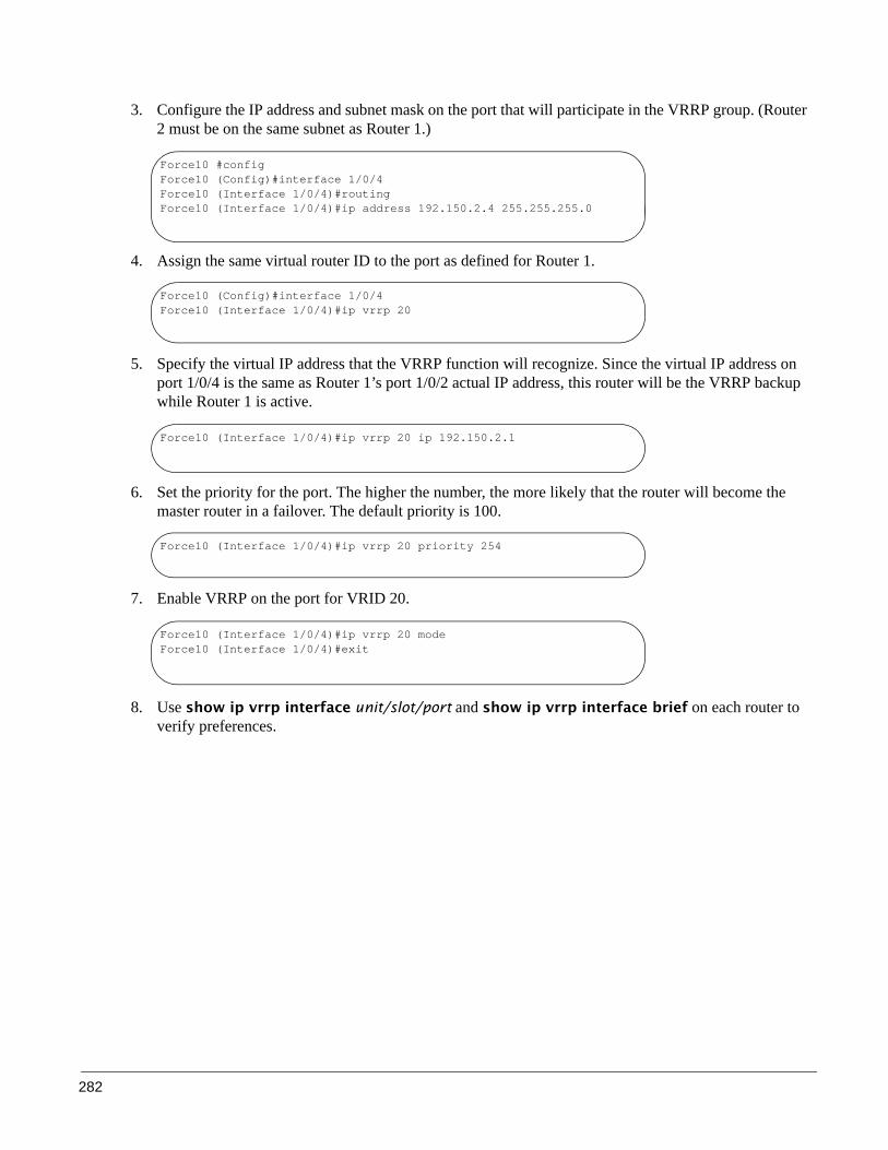
282
3. Configure the IP address and subnet mask on the port that will participate in the VRRP group. (Router 2 must be on the same subnet as Router 1.)
4. Assign the same virtual router ID to the port as defined for Router 1.
5. Specify the virtual IP address that the VRRP function will recognize. Since the virtual IP address on port 1/0/4 is the same as Router 1’s port 1/0/2 actual IP address, this router will be the VRRP backup while Router 1 is active.
6. Set the priority for the port. The higher the number, the more likely that the router will become the master router in a failover. The default priority is 100.
7. Enable VRRP on the port for VRID 20.
8. Use show ip vrrp interface unit/slot/port and show ip vrrp interface brief on each router to verify preferences.
Force10 #configForce10 (Config)#interface 1/0/4Force10 (Interface 1/0/4)#routingForce10 (Interface 1/0/4)#ip address 192.150.2.4 255.255.255.0
Force10 (Config)#interface 1/0/4Force10 (Interface 1/0/4)#ip vrrp 20
Force10 (Interface 1/0/4)#ip vrrp 20 ip 192.150.2.1
Force10 (Interface 1/0/4)#ip vrrp 20 priority 254
Force10 (Interface 1/0/4)#ip vrrp 20 modeForce10 (Interface 1/0/4)#exit

SFTOS Configuration Guide, Version 2.5.3.0 283
This chapter describes how to identify and resolve software problems related to SFTOS on an S-Series switch. Unless otherwise noted, the term switch refers to a standalone switch and to a switch stack. Additional troubleshooting information, such as LED descriptions, is provided in the hardware installation guide. This chapter consists of these sections:
• Recovering from Flash File System Corruption on page 283• Recovering from a Software Upgrade Failure on page 284• Recovering from a Lost Password on page 285• Recovering from Switch Stack Problems on page 285• Preventing Auto-negotiation Mismatches on page 286• Monitoring SFPs on page 288• Monitoring 10 GE Interfaces on page 289• Monitoring CPU and Memory Utilization on page 289• Troubleshooting No Output on the Console on page 290
Recovering from Flash File System Corruption
The S50 stores the startup configuration in an NVRAM section of flash memory. The startup configuration can become corrupted and unreadable if the write-to-memory operation does not succeed. You can recognize this condition via the event log messages in Figure 259 on page 283, which may appear after executing the write memory command.
Figure 259 Downloading Software to the Switch
Chapter 17 Troubleshooting
0xe536bd0 (Cnfgr_Thread ): dosFsLib.c : Malformed boot sector. Offset 0, value 2 55.
0xe536bd0 (Cnfgr_Thread ): dosFsLib.c : Problem finding volume data, trying to use the next block as boot block.
0xe536bd0 (Cnfgr_Thread ): dosFsLib.c : Malformed boot sector. Offset 0, value 2 49.
0xe536bd0 (Cnfgr_Thread ): dosFsLib.c : Ensure this device is formatted and partitions are properly handled.
Verifying CRC of file in Flash File System
TFTP receive complete... storing in Flash File System...
File transfer operation completed successfully.
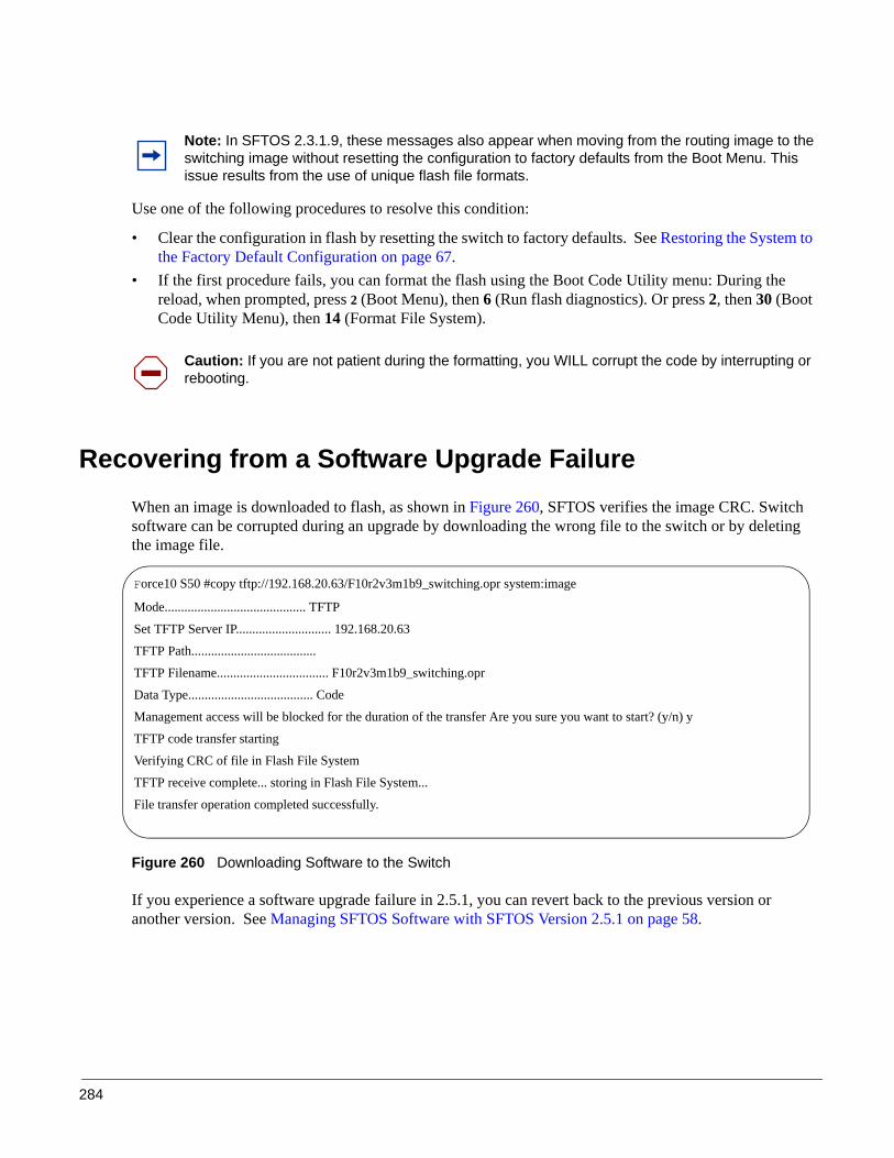
284
Use one of the following procedures to resolve this condition:
• Clear the configuration in flash by resetting the switch to factory defaults. See Restoring the System to the Factory Default Configuration on page 67.
• If the first procedure fails, you can format the flash using the Boot Code Utility menu: During the reload, when prompted, press 2 (Boot Menu), then 6 (Run flash diagnostics). Or press 2, then 30 (Boot Code Utility Menu), then 14 (Format File System).
Recovering from a Software Upgrade FailureWhen an image is downloaded to flash, as shown in Figure 260, SFTOS verifies the image CRC. Switch software can be corrupted during an upgrade by downloading the wrong file to the switch or by deleting the image file.
Figure 260 Downloading Software to the Switch
If you experience a software upgrade failure in 2.5.1, you can revert back to the previous version or another version. See Managing SFTOS Software with SFTOS Version 2.5.1 on page 58.
Note: In SFTOS 2.3.1.9, these messages also appear when moving from the routing image to the switching image without resetting the configuration to factory defaults from the Boot Menu. This issue results from the use of unique flash file formats.
Caution: If you are not patient during the formatting, you WILL corrupt the code by interrupting or rebooting.
Force10 S50 #copy tftp://192.168.20.63/F10r2v3m1b9_switching.opr system:image
Mode........................................... TFTP
Set TFTP Server IP............................. 192.168.20.63
TFTP Path......................................
TFTP Filename.................................. F10r2v3m1b9_switching.opr
Data Type...................................... Code
Management access will be blocked for the duration of the transfer Are you sure you want to start? (y/n) y
TFTP code transfer starting
Verifying CRC of file in Flash File System
TFTP receive complete... storing in Flash File System...
File transfer operation completed successfully.

SFTOS Configuration Guide, Version 2.5.3.0 285
Recovering from a Lost PasswordThe default CLI user, admin, has read/write access, with no password until you create one. Once created, the only way to recover from a lost admin password is to reload the switch using facory defaults. See Restoring the System to the Factory Default Configuration on page 67.
Alternatively, if the user is not admin, then you can assign a new password to the user. See Creating a User and Password on page 45.
Recovering from Switch Stack ProblemsIf a master switch (management unit of a stack) fails, or if a newly added switch in a stack is not recognized, the stacking algorithm in each S-Series switch sets the switch to automatically negotiate with connected units to determine the stack manager and unit numbering. See Management Unit Selection Algorithm on page 104 and Unit Number Assignment on page 104. You can manually intervene by selectively unplugging and reconnecting switches, and by manipulating the values that appear in the algorithm. See Adding a Switch to a Stack on page 107.
When a switch cannot transmit packets to a destination stack member, you may see console messages similar to the following:
Figure 261 Console Message: communication timeout
ATP, in the screen capture, above, refers to the SFTOS task used for stack member communication. These messages point to a communication problem with a stack member assigned an ID of d8:2e, which is derived from the last two digits of the MAC address of the switch. This condition may result from the following:
• Bad stacking cables or hardware components (connectors, bus...)• Improperly connected cable• Improperly seated module
An RPC timeout message like the following indicates a communication problem between the management unit and the member switch with the MAC address of 0:1:e8:d5:e6:20. The communication problem in this case was caused by the stack cable.
STACK: communication timeout to d8:2e
ATP: TX timeout, seq 24554. cli 778. to 1 tx cnt 21.
RPC - Timeout to CPU: 0:1:e8:d5:e6:20.

286
In addition to issuing the show switch and show stack commands, use the show stack-port diag command to display communication statistics for the stacking ports:
Figure 262 Using the show stack-port diag command
The meanings of the fields in the show stack-port diag command are described here:
• RBYT – Number of bytes received• RPKT – Number of packets received • TBYT – Number of bytes transmitted• TPKT – Number of packets transmitted• RFCS – Number of Frame Check Sequence (FCS) errors received• RFRG – Number of undersized packets received with bad FCS• RJBR – Number of oversized packets received with bad FCS• RUND – Number of undersized packets received with good FCS• ROVR – Number of oversized packets received with good FCS• TAGE – Aged packets• TABRT – Error packets
Preventing Auto-negotiation Mismatches
The IEEE 802.3ab auto-negotiation protocol manages the switch settings for speed (10 Mbps, 100 Mbps, and 1000 Mbps, excluding SFP module ports) and duplex (half or full). There are situations when this protocol can incorrectly align these settings, reducing performance.
1. Check the speed and/or auto-negotiation settings to ensure correct configuration.
Force10 S50 #show stack-port diag
1 - Stack Port A:
RBYT:5fdd RPKT:53 TBYT:adf13 TPKT:8f2
RFCS:0 RFRG:0 RJBR:0 RUND:0 ROVR:0
TAGE:0 TABRT:0
1 - Stack Port B:
RBYT:0 RPKT:0 TBYT:b2d03 TPKT:930
RFCS:0 RFRG:0 RJBR:0 RUND:0 ROVR:0
TAGE:0 TABRT:0
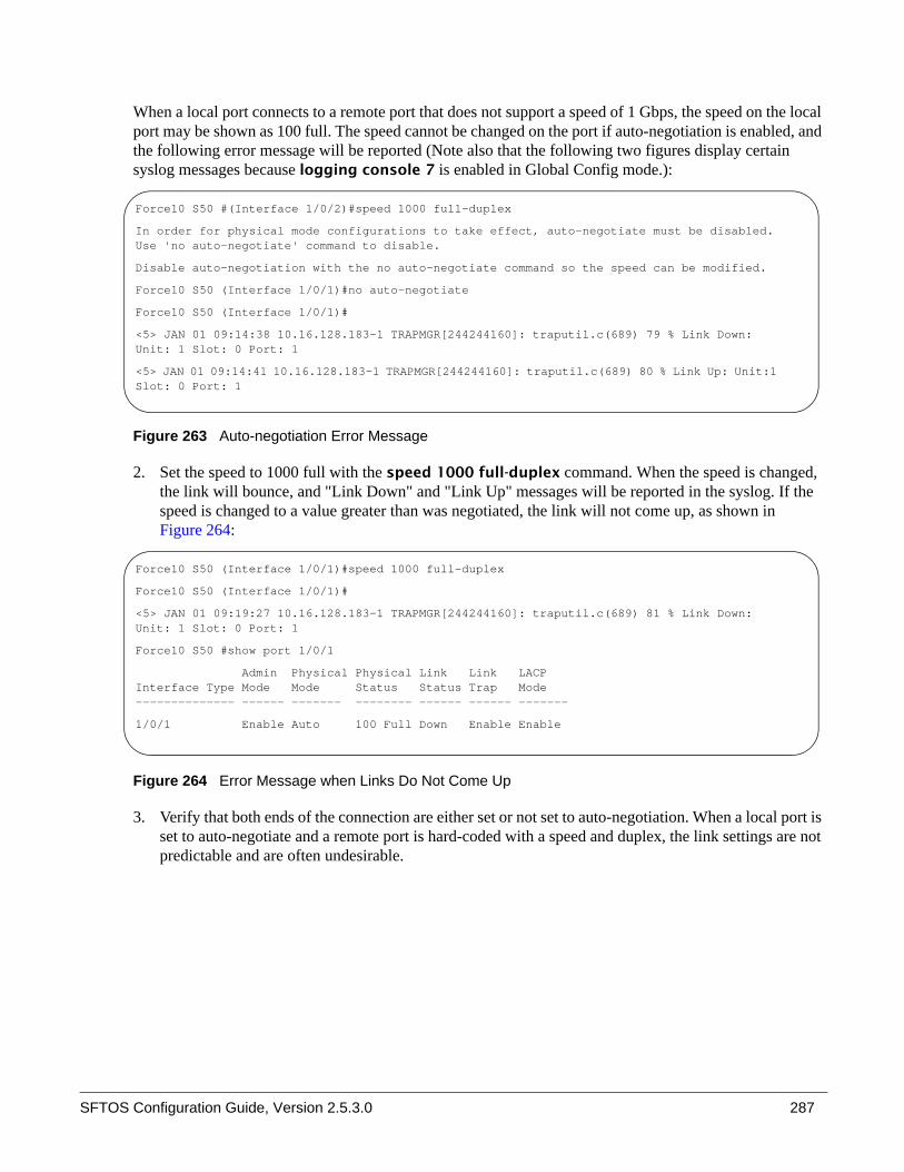
SFTOS Configuration Guide, Version 2.5.3.0 287
When a local port connects to a remote port that does not support a speed of 1 Gbps, the speed on the local port may be shown as 100 full. The speed cannot be changed on the port if auto-negotiation is enabled, and the following error message will be reported (Note also that the following two figures display certain syslog messages because logging console 7 is enabled in Global Config mode.):
Figure 263 Auto-negotiation Error Message
2. Set the speed to 1000 full with the speed 1000 full-duplex command. When the speed is changed, the link will bounce, and "Link Down" and "Link Up" messages will be reported in the syslog. If the speed is changed to a value greater than was negotiated, the link will not come up, as shown in Figure 264:
Figure 264 Error Message when Links Do Not Come Up
3. Verify that both ends of the connection are either set or not set to auto-negotiation. When a local port is set to auto-negotiate and a remote port is hard-coded with a speed and duplex, the link settings are not predictable and are often undesirable.
Force10 S50 #(Interface 1/0/2)#speed 1000 full-duplex
In order for physical mode configurations to take effect, auto-negotiate must be disabled. Use 'no auto-negotiate' command to disable.
Disable auto-negotiation with the no auto-negotiate command so the speed can be modified.
Force10 S50 (Interface 1/0/1)#no auto-negotiate
Force10 S50 (Interface 1/0/1)#
<5> JAN 01 09:14:38 10.16.128.183-1 TRAPMGR[244244160]: traputil.c(689) 79 % Link Down: Unit: 1 Slot: 0 Port: 1
<5> JAN 01 09:14:41 10.16.128.183-1 TRAPMGR[244244160]: traputil.c(689) 80 % Link Up: Unit:1 Slot: 0 Port: 1
Force10 S50 (Interface 1/0/1)#speed 1000 full-duplex
Force10 S50 (Interface 1/0/1)#
<5> JAN 01 09:19:27 10.16.128.183-1 TRAPMGR[244244160]: traputil.c(689) 81 % Link Down: Unit: 1 Slot: 0 Port: 1
Force10 S50 #show port 1/0/1
Admin Physical Physical Link Link LACP Interface Type Mode Mode Status Status Trap Mode -------------- ------ ------- -------- ------ ------ -------
1/0/1 Enable Auto 100 Full Down Enable Enable

288
Monitoring SFPsThe four fiber ports on the S50 and S50V share the interface numbers 45, 46, 47, and 48 with the corresponding copper ports. Only the fiber port or the copper port can be active at any given point in time. The fiber ports take precedence over the copper ports — if the S50 detects good links through both copper port 48 and fiber port 48, it will bring up the fiber port's link and bring down the copper port's link. The copper port will become active automatically if SFTOS detects a link down condition on the associated fiber port.
Figure 265 Front Panel of the S50
If a fiber port does not come up, use the following troubleshooting steps:
1. Verify you are using the correct SFP type, such as SR or LR. Optical specifications are available on the Force10 Networks website:
http://www.force10networks.com/products/specifications.asp
2. Reseat the SFP or swap it with a known good one.
3. Use a different pair of fiber cables, or at least verify that fiber end faces are clean. Clean the optical transceivers at both ends, as described in Cleaning and Inspecting Optical Fibers (http://www.pxit.com/pdf/whitepapers/Cleaning&Inspecting.pdf).
Note: The Force10 Networks quality assurance team has verified cases in which a fully functional port appears to be a bad port due to dirty optical connectors. The port fails loop testing with acceptable power measurement levels.Note: Force10 Networks recommends closely following the instructions in the referenced document on cleaning the optics.
SFTOS Configuration Guide, Version 2.5.3.0 289
Monitoring 10 GE InterfacesIf a 10-Gigabit Ethernet (10-GE) interface does not reach a link up state, use the following steps:
1. Verify that you are using the correct XFP type. Optical specifications are available on the Force10 Networks website:
http://www.force10networks.com/products/specifications.asp
2. Reseat the XFP or swap it with a known good one.
3. If you are using an XFP, connect one single fiber cable (as opposed to a pair) linking the Tx and Rx of the same XFP.
4. Cross-connect ports 49 and 50.
5. If you are using a CX4 module, adjust the preemphasis values with the cx4-cable-length {long | medium | short} command. Reducing the drive strength lowers the intensity (amplitude) of the signal being driven to the other end.
Monitoring CPU and Memory UtilizationIn SFTOS Version 2.5.1 and later, you can use the show process cpu command to monitor CPU utilization. A high value (probably over 40%) for the ipMapForwardingTask indicates that packet forwarding decisions are being made by the CPU and not by the hardware forwarding tables. This condition normally occurs when the hardware receives packets with a destination address not found in the hardware table. Hardware passes the packet up to the CPU. When the system finishes processing these packets, or a route has been established for these destinations (the hardware table has been updated with the new entries), the CPU response returns to normal.
In SFTOS Version 2.5.1 and later, you can use the show memory command to monitor overall memory utilization.
Software Forwarding
The process discussed above is often referred to as “software forwarding”, and sometimes “forwarded by the CPU” or “CPU routing”, where the system receives a unicast packet whose destination IP address cannot be resolved in the hardware, and so the packet is sent to the CPU to forward.
The routing software first looks for the destination MAC address in the ARP table, which it maintains. If it finds the address in the ARP table, it sends the packet to the Layer 2 application, which resolves it and finds the egress port from which to send it. If the software cannot find the destination in the ARP table, it sends an ARP request. After receiving the ARP reply, the Layer 2 tables can be updated, and subsequent
Note: The used and free memory amounts will be less than the total amount of memory. The show memory command displays only memory allocated by the SFTOS kernel. It does not take into account memory reserved for other functions, such as loading the system image.

290
packets can be routed by the hardware. In normal situations, the ARP request requires a small CPU hit, and CPU utilization drops once the destination is resolved.
Possible situations that require software forwarding for an extended period of time include:
• The system receives a lot of traffic with unresolvable destinations. The software constantly sends ARP requests for these packets, but no replies are received.
• The system receives packets with destination MAC addresses that cannot be resolved in the MAC Address table, but the destination IP address can be resolved in the ARP table. In this case, the hardware keeps sending the packets up to the CPU to retrieve ARP table entries to return to the Layer 2 application, but the Layer 2 application cannot find an associated egress interface from the MAC Address table.
The root cause, in most of these cases, is that the MAC Address table entry (Layer 2) times out earlier than the ARP Table entries (Layer 3). Make sure that the Layer 2 timeout period is longer than the Layer 3, and make sure that the ARP is configured to be a dynamic renew (the default).
In most network topologies, traffic flows are bidirectional. Therefore the Layer 2 table entries are constantly relearned/refreshed. However, in some cases, where the traffic flows are uni-directional, the Layer 2 entries time out before the Layer 3 entries, so the packets go to the CPU until the Layer 3 entries are timed out and new ARP requests are sent.
Configuring default/static routes does not help. Default routes create a static Layer 3 entry, but Layer 2 entries are still subject to timeouts in SFTOS.
Troubleshooting No Output on the ConsoleYour console might experience a temporary or seemingly permanent inability to display output. This symptom may be caused by one of the following transitory conditions:
• The switch is experiencing very high CPU utilization — a large number of frames for which there is no hardware forwarding entry or a large number of protocol packets being forwarded to the CPU for processing.
• Data is being transferred to or from the switch via TFTP, or the running configuration is being written to non-volatile memory. During these operations, all management access to the switch is blocked.
• The management unit in a stack is propagating the configuration to the member switches. • A remote connection to the switch console via a communication server has been lost. To determine
whether this symptom is occurring, ping the communications server. If the pings succeed, attempt to log into the server and kill the session connecting to your switch. Then re-connect.
• A topology loop is occurring in the network and flooding a large number of broadcasts or unknown unicast frames to all working interfaces in the same VLAN. Such excessive frame flooding can lead to high CPU utilization as the switch becomes overwhelmed with processing the unwanted frames. To prevent unwanted flooding, try the following: — Enable Spanning Tree. In SFTOS, Spanning Tree is disabled by default. — Shut down any ports not being used.

SFTOS Configuration Guide, Version 2.5.3.0 291
— Exclude VLAN 1 from all ports except the port used as the management port, as shown in the following example configuration for SFTOS Version 2.3.1.
Figure 266 Dedicating a Management Port on a Non-Default VLAN
Use the following steps to troubleshoot the symptom of no output at the switch console:
1. Verify a straight-through cable is connected to the switch console port. To connect the switch's console port to a PC, use the included DB-9 connector.
2. Verify your terminal emulation software is set to the following values (Note: If you are using Hyperterminal, select Restore Defaults to configure these values.):
Figure 267 Using the show serial Command to Determine Terminal Settings
3. If you contact the Force10 Technical Assistance Center, please have the following information:
• How long did it take for the switch to show a response to a keystroke? • Was the switch able to pass user traffic while the issue was occurring?
Force10 S50 #config
Force10 S50 (Config)#interface 1/0/26
Force10 S50 (Interface 1/0/26)#no shutdown
Force10 S50 (Interface 1/0/26)#exit
Force10 S50 (Config)#interface vlan 10
Force10 S50 (Conf-if-vl-10)#untagged 1/0/26
Force10 S50 (Conf-if-vl-10)#exit
Force10 S50 (Config)#interface managementethernet
Force10 S50 (Config-if-ma)#ip address 10.16.128.167 255.255.255.0
Force10 S50 (Config-if-ma)#vlan participation 10
Force10 S50 (Config-if-ma)#exit
Force10 S50 (Config)#management route default 10.16.128.254
Force10 S50 (Config)#exit
Force10 S50 #ping 10.16.128.254
Send count=3, Receive count=3 from 10.16.128.254
!---Able to reach beyond the default gateway so:----!
Force10 S50 #ping 10.16.24.3
Send count=3, Receive count=3 from 10.16.24.3
Force10 S50 #
Force10 S50 #show serial Serial Port Login Timeout (minutes)............ 0Baud Rate (bps)................................ 9600Character Size (bits).......................... 8Flow Control................................... DisableStop Bits...................................... 1Parity......................................... none
292
• What was the LED status? (If the switch remains able to pass traffic, the port LEDs should continue to blink. In particular, during a broadcast storm, all of the port LEDs should be blinking. )
• Do the link LEDs continue to be lit on removal of the cable connected to the port?• Was the switch accessible via Telnet, SNMP, and/or HTTP? • What type of traffic was flowing through the system? • Were any other S50s in the network experiencing the same problem? If not, are they positioned in the
network differently? Are they passing different kinds of traffic?
In addition, as a best practice, configure a remote management approach, such as SSH or HTTPS, to access an S-Series switch when console access is not possible but the switch is actively forwarding data traffic.

SFTOS Configuration Guide, Version 2.5.3.0 293
This appendix contains these sections:
• IEEE Compliance• RFC Compliance on page 294• SNMP-related RFCs on page 297• Industry MIBs Supported by SFTOS on page 298 • Force 10 MIBs on page 300• SNMP Traps on page 301
This appendix contains auxiliary information to the section Setting up SNMP Management on page 80 in the Management chapter and the techtip “What Should I Poll with SNMP?” on the iSupport website:https://www.force10networks.com/csportal20/KnowledgeBase/ToolTipsSSeries.aspx
For more on SNMP commands, see the SNMP Community Commands section in the Management chapter of the SFTOS Command Reference.
IEEE ComplianceSFTOS 2.5.1 conforms to:
• 802.lAB—Link Layer Discovery Protocol (LLDP)• 802.1D—Spanning Tree• 802.1p — Ethernet Priority with User Provisioning and Mapping• 802.1Q — Virtual LANs with Port based VLANs• 802.1s — Multiple Spanning Tree Protocol• 802.1v — Protocol-based VLANs• 802.1w—Rapid Spanning Tree Protocol• 802.1X — Port Based Authentication• 802.3ae—10 Gigabit Ethernet• 802.3ab—1000Base-T• 802.3ad—Link Aggregation• 802.3af—Power over Ethernet (PoE)• 802.3x — Flow Control• GMRP — Dynamic L2 Multicast Registration
Appendix A RFCs, MIBs, and Traps

294
• GVRP — Dynamic VLAN Registration
RFC Compliance The following is a list of the RFCs supported by SFTOS, listed by related protocol. The RFC categories under headings that include the parenthetical phrase “in Layer 3 Package only” are supported only in the Layer 3 Package (Routing) of SFTOS 2.5.1.
General Switching Protocols• RFC 768 — UDP• RFC 783 — TFTP• RFC 791 — IP• RFC 792 — ICMP (SFTOS aligns to the updated requirements in RFC 1812.)• RFC 793 — TCP• RFC 951 — BootP• RFC 1213 — Management Information Base for Network Management of TCP/IP-based internets
(MIB II)• RFC 1321 — Message Digest Algorithm• RFC 1493 — Definitions of Managed Objects for Bridges (Bridge MIB)• RFC 1534 — Interoperation between BootP and DHCP• RFC 2030 — Simple Network Time Protocol (SNTP) Version 4 for IPv4, IPv6 and OSI• RFC 2131 — (DHCP Client/Server component)• RFC 2132 — DHCP Options and BootP Vendor Extensions• RFC 2674 — The Q-BRIDGE of Definitions of Managed Objects for Bridges with Traffic Classes,
Multicast Filtering, and Virtual LAN Extensions (VLAN MIB)• Draft-ietf-magma-snoop-10.txt — IGMP Snooping
IP Multicast (in Layer 3 Package only)• RFC 1112 — IGMP• RFC 2236 — IGMP v2 • RFC 3376 — IGMPv3• RFC 2362 — PIM-SM • RFC 2365 — Administratively Scoped Boundaries• RFC 2932 — IPv4 Multicast Routing MIB • RFC 2933 — IGMP MIB• RFC 2934 — PIM MIB for IPv4 • Draft-ietf-pim-v2-dm-03 — PIM-DM• Draft-ietf-idmr-dvmrp-v3-10 — DVMRP

SFTOS Configuration Guide, Version 2.5.3.0 295
• Draft-ietf-magma-igmp-proxy-06.txt — IGMP/MLD-based Multicast Forwarding (IGMP/MLD Proxying)
• Draft-ietf-ssm-arch-05.txt — Source-Specific Multicast for IP• draft-ietf-magma-igmpv3-and-routing-05.txt — IGMPv3 and Multicast Routing Protocol Interaction
Management• HTML 4.0 Specification — December, 1997 (also HTML 4.01 Specification - December, 1999)• Java and JavaScript 1.3• RFC 854 — Telnet• RFC 855 — Telnet Option• RFC 1155 — SMI v1• RFC 1157 — SNMP v1/v2/v3• RFC 1867 — HTML/2.0 Forms with file upload extensions• RFC 2068 — HTTP/1.1 protocol as updated by draft-ietf-http-v11-spec-rev-03• RFC 2616 — HTTP/1.1• RFC 2295 — Transparent Content Negotiation• RFC 2296 — Remote Variant Selection; RSVA/1.0 State Management “cookies”
(draft-ietf-http-state-mgmt-05)• RFC 2572 — Message Processing and Dispatching for the Simple Network Management Protocol
(SNMP)• RFC 2573 — SNMP v3 Applications• RFC 2574 — User-based Security Model (USM) for Version 3 of the Simple Network Management
Protocol (SNMPv3)• RFC 2575 — View-based Access Control Model (VACM) for the Simple Network Management
Protocol (SNMP)• RFC 2576 — Co-existence between Version 1, Version 2, and Version 3 of the Internet-Standard
Network Management Framework• RFC 2578 — SMI v2• RFC 2579 — Textual Conventions for SMI v2• RFC 2580 — Conformance statements for SMI v2• RFC 2246 — The TLS Protocol, Version 1.0• RFC 2818 — HTTP over TLS• RFC 3268 — AES Ciphersuites for Transport Layer Security
OSPF (in Layer 3 Package only)• RFC 1587—NSSA option• RFC 1850—OSPF Version 2 Management Information Base • RFC 2328—OSPF v2

296
QoS• RFC 2474 — Definition of the Differentiated Services Field (DS Field) in IPv4 Headers• RFC 2475 — An Architecture for Differentiated Services • RFC 2597 — Assured Forwarding PHB Group• RFC 3246 — An Expedited Forwarding PHB (Per-Hop Behavior)• RFC 3260 — New Terminology and Clarifications for DiffServ
RIP (in Layer 3 Package only)• RFC 1058—RIP v1 (Obsoleted by RFC 2453)• RFC 1724—RIP Version 2 MIB Extension• RFC 2453—RIP v2
RMON• RFC 2819 — Remote Network Monitoring MIB: Ethernet Statistics Table, Ethernet History Control
Table, Ethernet History Table, Alarm Table, Event Table, Log Table
Routing (in Layer 3 Package only)• RFC 826 — Ethernet ARP • RFC 894 — Transmission of IP Datagrams over Ethernet Networks • RFC 896 — Congestion Control in IP/TCP Networks• RFC 1027 — Using ARP to implement Transparent Subnet Gateways (Proxy ARP)• RFC 1058 — RIP v1• RFC 1256 — ICMP Router Discovery Messages• RFC 1583 — OSPF v2• RFC 1723 — RIP v2• RFC 1765 — OSPF Database Overflow • RFC 1812 — Requirements for IP Version 4 Routers• RFC 2082 — RIP-2 MD5 Authentication• RFC 2096 — IP Forwarding Table MIB• RFC 2131 — (DHCP Relay component)• RFC 2328 — OSPF Version 2• RFC 2338 — Virtual Router Redundancy Protocol (VRRP)• RFC 2453 — RIP v2• RFC 3046 — DHCP Relay Agent Information Option• RFC 3101 — The OSPF “Not So Stubby Area” (NSSA) Option• RFC 3768 — VRRP – Virtual Router Redundancy Protocol• RFC 1724 — RIP v2 MIB Extension• RFC 1850 — OSPF MIB• RFC 2096 — IP Forwarding Table MIB

SFTOS Configuration Guide, Version 2.5.3.0 297
• RFC 2233 — The Interfaces Group MIB using SMI v2• RFC 2787 — VRRP MIB
Security• RFC 1492 — TACACS+• RFC 2865 — RADIUS• RFC 2866 — RADIUS Accounting• RFC 2868 — RADIUS Attributes for Tunnel Protocol Support • RFC 2869 — RADIUS Extensions• RFC 3579 — RADIUS Support for Extensible Authentication Protocol (EAP)• rfc2869bis — RADIUS Support for Extensible Authentication Protocol (EAP)• RFC 3580 — 802.1X RADIUS Usage Guidelines• RFC 3164 — The BSD Syslog Protocol • SSH v1/v2:
— Draft-ietf-secsh-transport-16 — SSH Transport Layer Protocol — Draft-ietf-secsh-userauth-17 — SSH Authentication Protocol— Draft-ietf-secsh-connect-17 — SSH Connection Protocol— Draft-ietf-secsh-architecture—14 — SSH Protocol Architecture— Draft-ietf-secsh-publickeyfile-03 — SECSH Public Key File— Draft-ietf-secsh-dh-group-exchange-04 — Diffie-Hellman Group Exchange for the SSH
Transport Layer Protocol
SNMP-related RFCsThe following is a list of other SNMP-related RFCs supported by SFTOS:
• draft-ietf-magma-mgmd-mib-03.txt — Multicast Group Membership Discovery MIB• Draft-ietf-idmr-dvmrp-mib-11.txt — DVMRP MIB• RFC 1157: SNMP v1• RFC 1212: Concise MIB Definition• RFC 1213: SNMP v2 (MIB-II)• RFC 1493: Bridge MIB• RFC 1643: Ethernet-like MIB• RFC 1724: RIP v2 MIB extension• RFC 1850: OSPF v2 MIB• RFC 1901: Community based SNMPv2• RFC 1905: Protocol Operations for SNMPv2• RFC 1906: Transport Mappings for SNMPv2• RFC 1907: Management Information Base for SNMPv2 • RFC 1908: Coexistence between SNMPv1 and SNMPv2

298
• RFC 2096: IP forwarding table MIB• RFC 2233: The Interfaces Group MIB using SMI v2• RFC 2570: SNMP v3• RFC 2571: An Architecture for Describing SNMP Management Frameworks• RFC 2665: Ethernet-like interfaces• RFC 2674: VLAN MIB• RFC 2787: Definitions of Managed Objects for the Virtual Router Redundancy Protocol (VRRP MIB)• RFC 2819: RMON (Groups 1, 2, 3, 9)
MIBs
Industry MIBs Supported by SFTOS
The first section of this list contains industry MIBs supported by SFTOS that is in the show sysinfo command output. The second section shows those not displayed by the show sysinfo command output. See also Force 10 MIBs on page 300.
Table 9 Industry MIBs Supported by SFTOS
MIB Description
BRIDGE-MIB — RFC 1493 Definitions of Managed Objects for Bridges (dot1d)
DIFFSERV-DSCP-TC — RFC 3289 Management Information Base for the Textual Conventions used in DIFFSERV-MIB
DIFFSERV-MIB — RFC 3289 Management Information Base for the Differentiated Services Architecture
ENTITY-MIB — RFC 2737 Entity MIB (Version 2)
Etherlike-MIB — RFC 3635 Definitions of Managed Objects for the Ethernet-like Interface Types
IEEE8021-PAE-MIB Port Access Entity module for managing IEEE 802.1X
IF-MIB — RFC 2863 The Interfaces Group MIB using SMIv2
LAG-MIB The Link Aggregation module for managing IEEE 802.3ad
P-BRIDGE-MIB — RFC 2674 The Bridge MIB Extension module for managing Priority and Multicast Filtering, defined by IEEE 802.1D-1998
POWER-ETHERNET-MIB Power Ethernet MIB
Q-BRIDGE-MIB — RFC 2674 The VLAN Bridge MIB module for managing Virtual Bridged Local Area Networks
RADIUS-ACC-CLIENT-MIB RADIUS Accounting Client MIB (RFC 2620)
RADIUS-AUTH-CLIENT-MIB RADIUS Authentication Client MIB (RFC 2618)
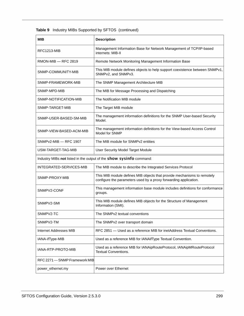
SFTOS Configuration Guide, Version 2.5.3.0 299
RFC1213-MIB Management Information Base for Network Management of TCP/IP-based internets: MIB-II
RMON-MIB — RFC 2819 Remote Network Monitoring Management Information Base
SNMP-COMMUNITY-MIB This MIB module defines objects to help support coexistence between SNMPv1, SNMPv2, and SNMPv3.
SNMP-FRAMEWORK-MIB The SNMP Management Architecture MIB
SNMP-MPD-MIB The MIB for Message Processing and Dispatching
SNMP-NOTIFICATION-MIB The Notification MIB module
SNMP-TARGET-MIB The Target MIB module
SNMP-USER-BASED-SM-MIB The management information definitions for the SNMP User-based Security Model.
SNMP-VIEW-BASED-ACM-MIB The management information definitions for the View-based Access Control Model for SNMP
SNMPv2-MIB — RFC 1907 The MIB module for SNMPv2 entities
USM-TARGET-TAG-MIB User Security Model Target Module
Industry MIBs not listed in the output of the show sysinfo command:
INTEGRATED-SERVICES-MIB The MIB module to describe the Integrated Services Protocol
SNMP-PROXY-MIB This MIB module defines MIB objects that provide mechanisms to remotely configure the parameters used by a proxy forwarding application.
SNMPV2-CONF This management information base module includes definitions for conformance groups.
SNMPV2-SMI This MIB module defines MIB objects for the Structure of Management Information (SMI).
SNMPV2-TC The SNMPv2 textual conventions
SNMPV2-TM The SNMPv2 over transport domain
Internet Addresses MIB RFC 2851 — Used as a reference MIB for inetAddress Textual Conventions.
IANA-ifType-MIB Used as a reference MIB for IANAifType Textual Convention.
IANA-RTP-PROTO-MIB Used as a reference MIB for IANAipRouteProtocol, IANAipMRouteProtocol Textual Conventions.
RFC 2271 — SNMP Framework MIB
power_ethernet.my Power over Ethernet
Table 9 Industry MIBs Supported by SFTOS (continued)
MIB Description

300
Force 10 MIBs
You can see this list of Force10-specific MIBs in the show sysinfo report:
Table 10 Force10-specific MIBs
MIB Description
FORCE10-REF-MIB Force10 Reference MIB
F10OS-POWER-ETHERNET-MIB F10OS Power Ethernet Extensions MIB
F10OS-SWITCHING-MIB F10OS Switching - Layer 2
F10OS-INVENTORY-MIB F10OS Unit and Slot configuration
F10OS-PORTSECURITY-PRIVATE-MIB Port Security MIB
F10OS-RADIUS-AUTH-CLIENT-MIB F10OS Radius MIB
F10OS-MGMT-SECURITY-MIB F10OS Private MIB for Management Security
F10OS-QOS-MIB F10OS Flex QOS Support
F10OS-QOS-ACL-MIB F10OS Flex QOS ACL
F10OS-QOS-DIFFSERV-EXTENSIONS-MIB F10OS Flex QOS DiffServ Private MIBs' definitions
F10OS-QOS-DIFFSERV-PRIVATE-MIB F10OS Flex QOS DiffServ Private MIBs' definitions
sftos_power_ethernet.my Power over Ethernet
Force10 MIBs not listed in the output of the show sysinfo command:
F10OS-DHCPSERVER-PRIVATE-MIB The Force10 Networks Private MIB for S-Series DHCP Server
F10OS-OUTBOUNDTELNET-PRIVATE-MIB The Force10 Networks Private MIB for SFTOS Outbound Telnet
F10OS-QOS-MIB The MIB definitions for Quality of Service Flex package
F10OS-QOS-COS-MIB The MIB definitions for Quality of Service - CoS Flex package
F10OS-SNTP-CLIENT-MIB This MIB module defines a portion of the SNMP MIB under the Force10 Networks enterprise OID pertaining to SNTP client configuration and statistical collection.
F10OS-KEYING-PRIVATE-MIB The Force10 Networks Private MIB for SFTOS Keying Utility

SFTOS Configuration Guide, Version 2.5.3.0 301
SNMP TrapsSNMP traps are the messages that are sent to designated trap receivers; they also appear in the report generated by the show logging traplogs command, an abbreviated sample of which appears in Figure 268. A replication of the trap also appears in the System log, as described in Displaying the SNMP Trap Log on page 96.
Figure 268 Using the show logging traplogs Command
Note that the report states that the trap log capacity is 256 traps. So, if the capacity is reached, the log wraps; in other words, newer traps replace the oldest ones.
For more on SNMP management, see the Setting up SNMP Management on page 80. For more on logging, see the Syslog chapter, most specifically Displaying the SNMP Trap Log on page 96.
Force10 #show logging traplogs
Number of Traps Since Last Reset............... 60926Trap Log Capacity.............................. 256Number of Traps Since Log Last Viewed.......... 59852
Log System Up Time Trap--- ------------------------ ------------------------------------------------- 0 3 days 10:23:55 Last or default VLAN deleted: VLAN: 10 1 3 days 10:23:55 Last or default VLAN deleted: VLAN: 1 2 1 days 05:27:21 Link Up: Unit: 1 Slot: 0 Port: 48 3 1 days 05:18:11 Failed User Login: Unit: 1 User ID: ker. 4 1 days 05:18:11 Failed User Login: Unit: 1 User ID: ker. 5 1 days 05:18:10 Failed User Login: Unit: 1 User ID: th. 6 1 days 05:18:09 Failed User Login: Unit: 1 User ID: ker. 7 1 days 05:18:09 Failed User Login: Unit: 1 User ID: ngth. 8 1 days 05:18:07 Failed User Login: Unit: 1 User ID: % Inva 9 1 days 05:18:07 Failed User Login: Unit: 1 User ID: ngth. 10 1 days 05:18:05 Failed User Login: Unit: 1 User ID: ker. 11 1 days 05:18:04 Failed User Login: Unit: 1 User ID: ngth. 12 1 days 05:18:02 Failed User Login: Unit: 1 User ID: ker.

302

SFTOS Configuration Guide, Version 2.5.3.0 303
Index
Symbols.opr extension 32{deny|permit} 207
Numerics10 GE module 12710 GigE 2810/100/1000 Base-T Ethernet line card, auto negotia-tion 1251000 Base-T (IEEE 802.3ab) 281583compatibility 266, 267, 26916k MAC Address Table 294k IPv4 Routing Table Entry 30802.3ad 173
AAccess Control Lists (ACLs) 205access control servers 44access-list 208, 209access-list command 212ACL 205ACL Commands 206ACL management VTY 210, 211Adding a Port-channel to a VLAN 181, 223addport 178admin user 44AF (assured forwarding) 190Applying Policies 191archive copy-sw command 103archive download-sw command 103ARP (RFC 826) 30ARP requests 290ARP table 289ATP 285audience 22authentication login command 148, 149authentication methods 143auto negotiation, line card 125Auto-negotiation Error Message 287autonegotiation protocol 286autonomous system (AS) 265
Bbaudrate command 38BE (best effort) 190Blackhole VLAN 217boot code 52Boot Code Utility menu 284
Boot Menu 67, 284boot sequence, system 67boot system command 115BootP 28BootP/DHCP relay agent 140bootpdhcprelay command 141bootpdhcprelay enable command 141bootpdhcprelay maxhopcount command 141bootpdhcprelay minwaittime command 141bootpdhcprelay serverip command 141border router 265, 268BPDU tunneling 239bridge 215Bridge Max Age parameter for MSTP 154BRIDGE-MIB 298Broadcast Storm Control, Enabling 213BSD 98buffered log 52, 74bulk configuration 182
Ccable, straight-through 291CD-ROM, S-Series 143Changing Management VLAN from Default 76channel-member command 179, 182CIDR (RFC 1519) 30Class 186Class of Service commands (CoS) 185class-map 73class-map match-all 73clear config command 65, 73clear counters command 131clear counters command, using 131clear lldp counters command 83clear lldp neighbors command 83clear pass command 45Clearing the Running Configuration 65Clearing/resetting, VLAN 222CLI banner 52CLI command modes 39CLI Overview 39CLI pagination 40clock time command 88clock, setting manually 87config command 38config file management 78, 79configuration file, delete 67configuration guide 22configuration script 52

304
configuration, restore to factory defaults 67Configuring a LAG (Port Channel) 178configuring a PVLAN 232Configuring a RADIUS Connection 146Configuring an Interface with an IP Address 48Configuring from the Network 66Configuring Private Edge VLANs 232Connecting a Cable to the Console Port 37console hang 290console port 291console troubleshooting 290Contact and Patents Information 23controlling traffic 185copy command 70copy nvram 70core port 239counter MIBs 80CPU routing 289CPU utilization 289Creating a Policy-Map 190Creating a User and Password 45Creating the Management Port IP 75CX4 module 289cx4-cable-length command 289
Ddate and time on the switch 87date, set 88DB-9 connector 291default gateway 42default management address 47default routes 290default user 44default VLAN 47, 76, 216default-router command 139definitions of unit, slot, port 33delete (image) command 59delete configuration file 67delete interface 178deleteport 176, 178deny permit, QoS 207Deploying DiffServ 188Designated Root (DR) 167destination port (mirroring port) 249DHCP pool 138DHCP server 137DHCP/BootP relay agent 137differences, S-Series and E-Series 31Differentiated Services (DiffServ) 185, 186Differentiated Services Code Point (DSCP) 186Differentiated Services for Voice over IP 202DiffServ code point (DSCP) 203DiffServ, managing 192DIFFSERV-DSCP-TC 298
DIFFSERV-MIB 298Displaying GARP Properties 230Displaying GARP, GVRP, GMRP 230Displaying LAGs (Port Channels) 184Displaying Logs 74Displaying Statistics 44Displaying Supported Features 43Displaying System Uptime 43Displaying the Current Software Version 54Distance Vector Multicast Routing Protocol (DVMRP)270dns-server command 139Document conventions 22DOS Protection 29dot1x defaultlogin command 148dot1x port-control command 148dot1x system-auth-control command 148dot3adTablesLastChanged 175Double VLAN commands 238Downloading a Software Image 54Downloading Files 52DSA 149DSCP 186, 203Dual Image Management commands 58, 59, 60dvlan-tunnel l2pdu-forwarding enable command 239dvlan-tunnel l2pdu-forwarding mac-address command239DVMRP 259, 270dynamic LAG 173, 183dynamically created VLAN 218
EECMP 31edge port enabling 163edge port feature 163EF (expedited forwarding) 190Egress Rules, VLAN 217enable CLI command mode 39enable command 38enable LACP 183enable passwd command 46Enable routing 280enabling all ports 46Enabling Broadcast Storm Control 213Enabling Differentiated Services 192Enabling IGMP Snooping 245Enabling Secure Management with SSH or SSL 149Enabling Traps 81encapsulation command (VLAN) 218encapsulation, link-level 259end station 216ENTITY-MIB 298errorlog 52E-Series differences 31

SFTOS Configuration Guide, Version 2.5.3.0 305
EtherChannel 173Etherlike-MIB 298Ethernet trunk 173Event log 52, 74Exempt Frames, VLAN 217exit 259, 261expedited forwarding (EF) 203External Type 1 265External Type 2 265
FF10OS-DHCPSERVER-PRIVATE-MIB 300F10OS-INVENTORY-MIB 300F10OS-KEYING-PRIVATE-MIB 300F10OS-MGMT-SECURITY-MIB 300F10OS-PORTSECURITY-PRIVATE-MIB 300F10OS-POWER-ETHERNET-MIB 300F10OS-QOS-ACL-MIB 300F10OS-QOS-COS-MIB 300F10OS-QOS-DIFFSERV-EXTENSIONS-MIB 300F10OS-QOS-DIFFSERV-PRIVATE-MIB 300F10OS-QOS-MIB 300F10OS-RADIUS-AUTH-CLIENT-MIB 300F10OS-SNTP-CLIENT-MIB 300F10OS-SWITCHING-MIB 300FCS (Frame Check Sequence) 286filedescr (image) command 59flags, trap 81Flow Control (IEEE 802.3x) 28Force10 MIBs 43Force10 SFTOS-POWER-ETHERNET-MIB 131FORCE10-REF-MIB 300Force10-specific MIBs 300Forceversion Command 159Format File System 284Forwarding Rules, VLAN 217Forwarding, Aging, and Learning 153Frame Check Sequence errors 286
GGARP (Generic Attribute Registration Protocol) 227GARP Commands 228GARP Timers 227gateway, default 42generate-keys.sh 149Generic Attribute Registration Protocol (GARP) 227Global Config CLI command mode 39Global Config Mode (SNMP traps) 82GMRP (GARP Multicast Registration Protocol) 227gmrp adminmode enable command 228GMRP commands 228gmrp interfacemode enable all command 228Group IDs 218
GVRP 218, 228GVRP (GARP VLAN Registration Protocol) 227gvrp adminmode enable command 228GVRP commands 228gvrp interfacemode enable command 228GVRP, Using 228
Hhardware installation guide 22Hardware installation guides 23hashing algoritm, traffic distribution 174help commands 40Hierarchical management 265Host Name, Setting the 78hostname command 78HTML-based Management 30HTTPS/SSL 30Hyperterminal 291
IIEEE 802.1d 28IEEE 802.1Q 233IEEE 802.1q 29IEEE 802.1Q tag 216IEEE 802.1Q VLANs 215IEEE 802.1s 28IEEE 802.1w 28IEEE 802.1X 143IEEE 802.1x 29IEEE 802.3 MAC interfaces 173IEEE 802.3ab 28IEEE 802.3ad 28IEEE 802.3ae 28IEEE 802.3af 131IEEE 802.3x 28IEEE8021-PAE-MIB 298IF-MIB 298IGMP (Internet Group Management Protocol) com-mands 245igmp command (VLAN) 218igmp enable command 245igmp interfacemode enable all command 245IGMP Proxy 259, 260IGMP Snooping 29image1 59, 60image2 59, 60Independent VLAN Learning (IVL) 153industry MIBs 298Ingress Rate Limiting 29inlinepower admin command 132inlinepower command 132inlinepower limit command 132inlinepower priority command 132

306
inlinepower threshold command 132inlinepower type command 132INTEGRATED-SERVICES-MIB 299Inter-area 265inter-area router 265interface 226, 259, 261, 264, 268, 271, 272, 273,274, 276, 281interface command 148, 261interface command (VLAN) 76Interface Config CLI command mode 39interface loopback 210interface loopback 0 command 212interface managementethernet command 47, 76interface managementethernet command (S50) 80interface managementethernet command example 75Interface modes
Layer 2 119Layer 3 119
Interface Port Channel Config mode 173interface port-channel command 179interface range command 182interface range ethernet range command, using 135Interface Range mode 182interface range port-channel command 182Interface types
100/1000 Ethernet 119, 12510-Gigabit Ethernet 119, 1251-Gigabit Ethernet 119, 125Management 125management 119Port Channel 120VLAN 120
interface unit/slot/port command 251interface vlan 218Interface VLAN CLI command mode 39interface vlan command 76, 213, 277interfaces
clearing counters 130Intra-area 265ip access-group 209ip access-group command 212ip address 257, 259, 264, 268, 276, 281ip address command 47, 277ip address command (VLAN) 218, 270ip address command for management example 75IP addresses
assigning IP address to interface 130ip dhcp excluded-address command 138, 139ip dhcp pool command 139ip dvmrp metric command (VLAN) 270ip dvmrp trapflags command 82IP forwarding 258ip igmp command (VLAN) 218, 270ip igmp last-member-query-count command (VLAN)
218, 270ip igmp proxy command 259ip igmp-proxy command 261ip igmp-proxy unsolicit-rprt-interval command 261ip mcast boundary command (VLAN) 218, 270ip mtu command (VLAN) 218IP multicast 218, 270IP Multicast Commands chapter 218, 270ip ospf 267, 269ip ospf areaid 267, 269ip ospf areaid command (VLAN) 218, 270ip ospf authentication-key command 274ip ospf command (VLAN) 218, 270ip ospf cost 267, 269ip ospf cost command 274ip ospf priority 267, 269ip ospf priority command 274IP PIM-DM commands 270ip pimdm mode command (VLAN) 270ip pimdm query-interval command (VLAN) 270IP PIM-SM (Protocol Independent Multicast—SparseMode) commands 270ip pim-trapflags command 82ip rip 264ip rip command (VLAN) 218, 270ip routing 258, 264, 268, 280ip routing command 257ip ssh command 151IP VLAN 226, 271ip vrrp 280, 282ip vrrp command (VLAN) 218, 270IPv4 (RFC 1812) 30IPv4 Router Discovery (RFC 1256) 30iSupport 22, 23iSupport (SNMP information) 80, 83IVL (Independent VLAN Learning) 153
JJumbo Frame Support 29
LLACP 183LACP (Link Aggregation Control Protocol) 182LACP enable 183LACP PDU 173, 175LAG 173LAG configuration (port channel) 178LAG described 173LAG Distribution Algorithm 174LAG Implementation 175LAG Load Distribution 174LAG maximums 175LAG, dynamic 173

SFTOS Configuration Guide, Version 2.5.3.0 307
LAG, static 173LAG-MIB 298Layer 2 header 215Layer 2 Multicast Forwarding 29Layer 3 mode
configuring 130enable traffic 125
Layer 3 Package 48Layer 3 Package Features 30Layer 3 Package of SFTOS 30Layer 3 protocols
configuring 125Layer 3 Routing 255limits, stack size 102, 107line card, auto negotiation 125line cards 101Line Config mode 38lineconfig command 38link aggregate group (LAG) 173Link Aggregation (LAG) 277Link Aggregation Commands 176Link Aggregation Control Protocol (LACP) 173, 182Link Aggregation Control Protocol Protocol Data Unit(LACP PDU) 173, 175Link Aggregation Groups (LAGs) 173Link Aggregation MIB Support 175Link Aggregation—IEEE 802.3 173Link Down messages 287Link Layer Discovery Protocol (LLDP) 83Link Up messages 287List of logging hosts 74LLDP 83lldp command 83lldp mode command 83load balancing with VRRP 279load-balancing algorithm, traffic 174local7 99logging 74
buffered 92persistent (Event log) 95types of Syslog servers supported 98
logging buffered command 91, 92logging buffered wrap command 91, 92logging cli-command command 91, 92logging console 7 command 152logging console command 91, 92logging facility command 97logging history 93logging host command 92, 97, 98logging host reconfigure command 92, 97logging host remove command 92, 97logging severity levels 94logging syslog command 92, 97logical segments 215
Login Access Control 29logs 74loopback ACL example 213loopback configuration 212loopback interface 119loopback interface command 119loopback interface restrictions 212
MMAC Access Control List (ACL) 206mac access-group 207mac access-list extended 206mac access-list extended rename 207MAC address 167MAC address, last two digits of 285MAC DA 270MAC Destination Address (DA) 270MAC-based Port Security 29makestatic command 230makestatic command (VLAN) 218Management 29management access to the switch 149management ACL example 213Management interface 125management interface 119management IP address 75management IP interface 47, 80Management Preference and MAC Address 112Management Preferences 111management route default command 47management route default command example 75management unit 101Management Unit Selection Algorithm 104management VLAN 76, 77management VTY ACL 210, 211managing config files 78managing running-config and system-config files 79Managing SNMP Traps 81Max Age parameter for MSTP 154Max Hops parameter for MSTP 154maximum transmission unit (MTU) 259MD5 143member command 103, 108member units 101memory 289message log 52MFC (multicast forwarding cache) 259MIB list, supported 43MIB OIDs 80MIB, Power over Ethernet 299, 300MIB, Power-Ethernet 131MIBs 298MIBs, counter 80MIBs, Force10-specific 300

308
MIBs, supported industry 298mirrored port (source port) 249mode dot1q-tunnel command 239mode keyword 281modes, Global Config (SNMP traps) 82modes, Privileged Exec (SNMP traps) 82modes, Router OSPF Config (SNMP traps) 82monitor session 1 251monitor session 1 destination command 250monitor session 1 mode command 250monitor session 1 source interface command 250Monitoring DiffServ 192Monitoring IGMP Snooping 246movemanagement command 103, 104, 108MST Regions (Multiple Spanning Tree regions) 157MSTP (IEEE 802.1s) 28MSTP (Multiple Spanning Tree Protocol) 153MSTP Configuration Example 164MSTP Max Hops parameter 154MSTP Standards 157MTU (Maximum Transmission Unit) size 218mtu command 238mtu command (VLAN) 218multicast 218, 270multicast forwarding cache (MFC) 259Multicast Protocols (Layer 2) 29Multicast Protocols (Layer 3) 31Multicast Routing Protocols (DVMRP, PIM-DM, andPIM-SM) 259Multi-Link Trunking (MLT) 173Multiple Spanning Tree Protocol (MSTP) 153, 158Multiple Spanning-Tree Protocol 156
Nname command (VLAN) 76, 218native VLAN 216, 218, 233network command 139NIC bonding 173NIC teaming 173 176, 178, 183no ip telnet server enable command 152no monitor command 250no monitor session 252no monitor session 1 destination command 250no monitor session 1 mode command 250no monitor session 1 source interface command 250no port-channel 176no shutdown command 46no spanning-tree edgeport 178non-paged option 41null interface 119
Oobjectives 21Open Shortest Path First (OSPF) 265OpenSSH URL 150OSPF 265, 273
RFC 2328, RFC 1587, RFC 1765, RFC 2370 30OSPF Commands chapter 218, 270OSPF intervals 275OSPF priority 274ospf priority command 267OSPF timers 275out-of-band access methods 36
Ppacket-forwarding distribution algorithm 174pagination, controlling CLI 40partitions 215password recovery 44patents 23P-BRIDGE-MIB 298Persistent log 74persistent log 52persistent log (Event log) 95PIM-DM 259PIM-SM 259PoE power budget 131police-simple 196Policy 186port 216Port Channel Range 182port channel. See also LAG. 173Port channels
defaults 120port channels 173Port defined 33port lacpmode enable command 176, 178, 183port lacptimeout command 183Port Mirroring 29Port Mirroring Configuration 250Port Naming Convention 33port routing 258port security configuration 143port teaming 173port trunking 173port-channel command 179port-channel enable all 176, 178, 183port-channel linktrap 176port-channel name 176port-channel staticcapability 178port-channel staticcapability command 179Portfast 163port-security 251port-security command 251

SFTOS Configuration Guide, Version 2.5.3.0 309
power budget, PoE 131Power over Ethernet (PoE) 131Power over Ethernet MIB 299, 300power supply 131power_ethernet.my 299Power-Ethernet MIB 131POWER-ETHERNET-MIB 298preemphasis (CX4) 289Private Edge VLAN 216Private Edge VLANs 232Privileged Exec CLI command mode 39Privileged Exec Mode (SNMP traps) 82probe port 249protected port group, configuring 232protocol group command (VLAN) 218Protocol Independent Multicast—Dense Mode(PIM-DM) 270Protocol Independent Multicast—Sparse Mode(PIM-SM) 270protocol lacp command 177, 179, 183protocol static command 179Proxy ARP (RFC 1027) 30PVLAN 232PVLAN, configuring 232
QQ-BRIDGE-MIB 298QinQ 238QoS
802.1p Priority Marking 29ACLs 29Bandwidth-based Rate Limiting 29Layer 2 Classification 29Layer 3 DSCP 29Priority Queues 29
Quality of Service (QoS) 185Quick Reference 23
RRADIUS 29, 44, 143radius accounting mode command 146, 148RADIUS Connection, Configuring a 146radius server host acct command 148radius server host auth command 148, 149radius server host command 146radius server key acct command 148radius server key auth command 148, 149radius server key command 146radius server msgauth command 146radius server primary command 146, 149radius server retransmit command 146radius server timeout command 146RADIUS-ACC-CLIENT-MIB 298
RADIUS-AUTH-CLIENT-MIB 298Rapid Spanning Tree (IEEE 802.1w) 28Rapid Spanning Tree Protocol (RSTP) 153Read/Write Access Using SNMP V3 45Related Documents 22release notes 22reload command 60, 65, 67, 104, 115Remote Authentication Dial-In User Service (RADIUS)146resetting the stack 104restore configuration to factory defaults 67Restoring the Configuration to Factory Defaults 78RFC 1058 263RFC 1112 294RFC 1122 28RFC 1157 295, 297RFC 1212 297RFC 1213 294, 297RFC 1493 294, 297, 298RFC 1534 137RFC 1542 28, 137RFC 1643 297RFC 1723 263RFC 1724 296, 297RFC 1850 295, 297RFC 1901 297RFC 1905 297RFC 1906 297RFC 1907 43, 297, 299RFC 1908 297RFC 2096 296, 298RFC 2131 28, 137, 294, 296RFC 2132 137RFC 2233 298RFC 2236 294RFC 2241 137RFC 2242 137RFC 2338 279RFC 2570 298RFC 2571 298RFC 2572 295RFC 2574 295RFC 2575 295RFC 2576 295RFC 2665 298RFC 2674 294, 298RFC 2737 298RFC 2787 298RFC 2819 43, 83, 296, 298, 299RFC 2863 298RFC 2865 297RFC 2933 294RFC 2934 294RFC 3289 298

310
RFC 3635 298RFC 3768 279RFC 768 28, 294RFC 783 294RFC 791 28, 294RFC 792 28, 294RFC 793 28, 294RFC 854 295RFC Compliance 294RFC list 294RFC list, supported 43RFC1213-MIB 299RIP Commands chapter 218, 270RIPv1 263RIPv1/v2 30RIPv2 263RMON 30
Important Points to Remember 84rmon alarm command 84rmon collection statistics command 84rmon event command 84show rmon alarms brief command 84show rmon alarms command 84show rmon command 84show rmon events brief command 84show rmon events command 84show rmon history brief command 84show rmon history command 84show rmon log brief command 84show rmon log command 84show rmon statistics brief command 85show rmon statistics command 85
RMON (Remote Network Monitoring) MIB 83rmon alarm command 85RMON Command Set 84rmon event command 85RMON-MIB 43, 299routed VLAN 226, 271router ospf 267, 269Router OSPF Config Mode (SNMP traps) 82router rip 264, 276router-id 267, 269routing 259, 264, 268, 281routing domain 265Routing image of SFTOS 30Routing Information Protocol (RIP) 263RPM 101RSA1 149RSA2 149RSMLT 173RSTP (Rapid Spanning Tree Protocol) 153Run flash diagnostics 284Running Configuration, Clearing 65running-config and system-config files, managing 78,
79
SS2410 documentation 21S50
interface managementethernet command 80snmp-server community command 80
S50V switch 131Saving the Startup Config to the Network 66script 52script apply command 72script apply startup-config command 65script delete command 70script list command 74script show scriptname.scr 69Secure SHell (SSH) 143, 149Security and Packet Control Features 29serial session-limit command 38serial session-timeout command 38serial timeout command 38Service 186service dhcp command 139service-policy 191session-limit command 38session-timeout command 38set clock 88set garp timer join command 228set garp timer leave command 228set garp timer leaveall command 228set igmp groupmembership-interval command 245set igmp maxresponse command 246set igmp mcrtexpiretime command 246Setting Network Parms 47Setting the Enable Password 46Setting the Host Name 78setting the system clock manually 87Setting Up a Management VLAN 50severity levels, logging 94SFTOS Command Reference 23SFTOS Configuration Guide 23SFTOS versions 27, 30sftos_power_ethernet.my 300Shared VLAN Learning (SVL) 153shell script, generate-keys.sh 149show authentication command 144show bootpdhcprelay command 141show bootvar command 114, 115show class-map command output 194show clock command 88show diffserv command output 195show diffserv service brief command output 195show dot1q-tunnel command 239show dvlan-tunnel command 239show dvlan-tunnel l2pdu-forwarding command 239

SFTOS Configuration Guide, Version 2.5.3.0 311
show eventlog command 74, 92, 95show eventlog example 95show garp command 230, 231show gmrp configuration command 230show gvrp configuration all command 229show gvrp configuration command 230, 231show hardware command 41, 54show igmp interface 246show igmpsnooping 246show igmpsnooping interface 246show inlinepower command 132show interface 44show interface command (S50) sample output 122show interface ethernet 44show interface ethernet command 158, 171show interface ethernet sample output 123, 124show interface ethernet switchport 44show interface ethernet unit/slot/port command 124show interface loopback command 212show interface managementethernet command 47, 76,77show interface managementethernet command exam-ple 75show interface port-channel brief command 178show interface port-channel command 180show interface sample output (S50V) 122show interface switchport 44show interface switchport sample output 121show interface-ethernet command 214show interfaces cos-queue command 123show interfaces cos-queue sample output 123show interfaces port-channel brief command 224, 278show interfaces switchport command 232show ip access-lists 209show ip dhcp server statistics command 140show ip igmp-proxy command 262show ip igmp-proxy groups command 262show ip igmp-proxy groups detail command 262show ip igmp-proxy interface command 262show ip interface brief command 125, 256show ip interface brief sample output 125show ip interface command 278show ip interface vlan 278show ip interface vlan command 278show ip ospf command 273, 274show ip ospf interface vlan command 275show ip ssh command 151show lldp interface command 83show lldp local-device command 83show lldp neighbors command 83show lldp remote-device command 83show logging buffered command 93show logging command 74, 92, 93, 95, 152show logging command example 93
show logging history command 74, 92, 93show logging hosts command 74, 91, 92, 98show logging hosts example 98show logging traplogs command 74, 92, 96show logging traplogs example 96, 301show mac access-list 207show mac access-lists 208show mac-address-table igmpsnooping command 247,248show mac-addr-table command example 116show memory command 289show monitor 252show monitor session 1 250show monitor session command example 250show policy-map command 197show policy-map interface command 198show policy-map policy-map-name command 198show port 253show port all 253show port all command sample output 126show port command 242show port command example 253show port sample output 129show port-channel all command 178, 184show port-channel brief 178show radius accounting statistics command 147show radius command 147show radius statistics command 147show rmon alarms brief command 84, 85show rmon alarms command 84show rmon events brief command 84show rmon events command 84show rmon history brief command 84show rmon history command 84show rmon log brief command 84show rmon log command 84show rmon statistics brief command 85show rmon statistics command 85show running-config 68show running-config command 52, 77, 242, 243show running-config sample output 120show serial command 38show slot command 127show slot sample output 127show sntp client command 88, 89show sntp command 88show sntp server command 88, 90show spanning-tree brief command 166show spanning-tree command 167show spanning-tree interface command 166show spanning-tree mst port detailed command 168show spanning-tree mst port summary command 168,169show spanning-tree mst port summary report 169, 170

312
show spanning-tree summary command 166show stack command 114, 115, 286show stack-port command 103show stack-port command example 116show stack-port counters command 103show stack-port counters Command Example 117show stack-port diag command 286show stack-port diag command fields 286show storm-control command 214show supported switchtype command 103, 108show switch command 40, 54, 103, 108, 114, 115,286show switchport protected command 232show sysinfo command 41, 300show tacacs command 144show tech-support command 95show tech-support command (list of output) 41show tech-support non-paged command 41show terminal command 40show trapflags command 82show users command 45show version command 41, 54show vlan association command 242show vlan brief command 229, 230, 242, 243show vlan command 242show vlan command example 243, 244show vlan id command 76, 224, 242, 278show vlan id command example 244show vlan name command 242show vlan port command 242Showing Created Users 45Showing Network Settings 42Simple Network Time Protocol (SNTP) 87Slot defined 33SMLT 173SNMP Management, Setting up 80SNMP traps defined 80SNMP Traps, Managing 81SNMP v1/v2c 30SNMP-COMMUNITY-MIB 299SNMP-FRAMEWORK-MIB 299SNMP-MPD-MIB 299SNMP-NOTIFICATION-MIB 299snmp-server community command (S50) 80snmp-server enable traps bcaststorm command 82snmp-server enable traps linkmode command 82snmp-server enable traps multiusers command 82snmp-server enable traps stpmode command 82snmp-server traps enable command 82SNMP-TARGET-MIB 299snmptrap snmpversion command 82SNMP-USER-BASED-SM-MIB 299SNMPv2-MIB 43, 299SNMPV2-TC 299
SNMPV2-TM 299SNMP-VIEW-BASED-ACM-MIB 299snmpwalk 131SNTP 30, 87sntp broadcast client poll-interval command 88, 89sntp client mode broadcast command 89sntp client mode command 88sntp client mode unicast command 89sntp client port command 88, 89sntp server command 88, 89sntp unicast client poll-interval command 88sntp unicast client poll-retry command 88sntp unicast client poll-timeout command 88software forwarding 289software upgrades in stacks 102, 105software version contentions in stacks 107software version, viewing 106source port 249Spanning Tree Protocol (IEEE 802.1d) 154Spanning Tree Protocol (STP) 153spanning-tree command 51, 161spanning-tree msti cost command 162spanning-tree msti external-cost command 162spanning-tree msti priority command 162spanning-tree port mode enable all command 51, 161spanning-tree port mode enable command 161speed 1000 full-duplex command 287S-Series 265S-Series CD-ROM 149S-Series product CD-ROM 143S-Series stack 101S-Series Training slides 143S-Series troubleshooting 283SSH 36SSH keys 149SSH2 Server Support 29SSHv2 30stack command 103stack maximum 102, 107stack member communication 285stack size limits 102, 107stack VLANs 238Stackability Commands 103Stackability Features 101stacking cables, bad 285stacking features 30startup configuration 65startup configuration file 52startup-config 52startup-config file 65static LAG 173Static LAG CLI Management 178Static LAG Requirements 175static route 290

SFTOS Configuration Guide, Version 2.5.3.0 313
storm control, enabling 213storm-control broadcast command 213STP 51STP (Spanning Tree Protocol) 28, 153STP BPDU tunneling 239STP protocol Version parameter 154straight-through cable 291subnets 258SunOS UNIX system 98SVL (Shared VLAN Learning) 153switch management access 149switch priority command 103, 104, 107switch renumber command 103, 107Switching Features 153switchport protected (Global Config) command 232switchport protected (Interface Config) command 232Syslog 30syslog host settings, changing 97system boot sequence 67System log 52, 74system log command set 91system software file 52
TTACACS Configuration mode 145TACACS Server Host Configuration Options 145TACACS+ 44
Choosing TACACS+ as an Authentication Method143
deleting a server host 146TACACS+ server connection options 145tacacs-server host command 144, 145tagged command (VLAN) 218Tech Tips and FAQ, S-Series 23Telnet 36Telnet (RFC 854) 30terminal emulation 291terminal length command 40TFTP 149TFTP (RFC 783) 30TFTP procedure 54time, set 88timeout command 38timeout, set console inactivity 38timestamps in logs 87timezone 87traffic distribution algorithm 174Training, S-Series 143Transferring Files 53transport command 38trap log 52Trap Management 81trapflags command 82Traps 74
Troubleshooting 293troubleshooting S-Series 283trunking 221tunnel port 239
UUDP 28Unit defined 33Unit Number Assignment 104unit, member 101Unsetting Management Preference 112untagged command 277untagged command (VLAN) 218update bootcode command 59uplink port 239user authentication methods 143User Exec CLI command mode 39User Management 44username passwd command 45users defaultlogin command 144, 149Using GVRP 228Using the “show class-map” Command 193Using the “show diffserv” Command 194Using the “show policy-map” Command 195Using the “show service-policy” Command 198USM-TARGET-TAG-MIB 299
VVerifying Management Port Connectivity 77Verifying Management Port Network 77Verifying Switch Numbers and OS Version 41Viewing Software Version 40Virtual LAN (VLAN) 215virtual router ID (VRID) 281Virtual Router Redundancy Protocol (VRRP) 279virtual routers 279VLAN 1 47, 216VLAN Configuration, Showing 242vlan database 220, 221, 222, 226, 236, 237, 271,272VLAN Database Mode Commands 218VLAN ID Options 217vlan participation command 76vlan participation command (management VLAN) 76vlan routing 226, 271, 272vlan routing (ip address) 226, 271, 272VLAN routing, enable 276VLAN stacking 238VLAN switch 215VLAN tunneling 238VLAN, default 76VLAN, IEEE 802.1Q 215VLAN, management 76
314
VLANs 120VLANs Implementation 217VLAN-stack commands 238VoIP support 202VRID 281VRRP 279
primary IP address 279secondary IP address 279
VRRP (RFC 2338) 30VRRP group 281VRRP group ID 281VRRP groups 279
VRRP, load balancing 279VT100 emulation 36
WWhat Should I Poll with SNMP? 83
XXmodem procedure 54
Zzip file, SSH and SSL 149