Embed Size (px)
Citation preview
SFTOS Configuration Guide
Version 2.1.4 May 2005 100-00028-02
Copyright 2005 Force10 NetworksAll rights reserved. Printed in the USA. April 2005.Force10 Networks reserves the right to change, modify, revise this publication without notice.
TrademarksCopyright 2005 by Force10 Networks, Inc. All rights reserved. Force10, the Force10 logo, E1200, E600, E300, EtherScale, TeraScale and FTOS are trademarks of Force10 Networks, Inc. All other brand and product names are registered trademarks or trademarks of their respective holders.
Statement of ConditionsIn the interest of improving internal design, operational function, and/or reliability, Force10 Networks reserves the right to make changes to products described in this document without notice.Force10 Networks does not assume any liability that may occur due to the use or application of the product(s) described herein.
USA
Federal Communications Commission (FCC) StatementThis equipment has been tested and found to comply with the limits for a Class A digital device, pursuant to Part 15 of the FCC rules. These limits are designated to provide reasonable protection against harmful interference when the equipment is operated in a commercial environment. This equipment generates, uses, and can radiate radio frequency energy. If it is not installed and used in accordance to the instructions, it may cause harmful interference to radio communications. Operation of this equipment in a residential area is likely to cause harmful interference, in which case users will be required to take whatever measures necessary to correct the interference at their own expense.
Canadian Department of Communication StatementThe digital apparatus does not exceed the Class A limits for radio noise emissions from digital apparatus set out in the Radio Interference Regulations of the Canadian Department of Communications. Attention: Le present appareil numerique n’ emet pas de perturbations radioelectriques depassant les normes applicables aux appareils numeriques de la Class A prescrites dans le Reglement sur les interferences radioelectriques etabli par le ministere des Communications du Canada.
VCCI Compliance for Class A Equipment (Japan)
This is Class A product based on the standard of the Voluntary Control Council For Interference by Information Technology Equipment (VCCI). If this equipment is used in a domestic environment, radio disturbance may arise. When such trouble occurs, the user may be required to take corrective actions.
Caution: This device is a Class A product. In a domestic environment, this device can cause radio interference, in which case, the user may be required to take appropriate measures.
Contents . . . . . . . . . . . . . . . . . . . . . . . . . . . . . . . . . . . . . . . . . . . . . . . . . . . . . . . . . . . . . . . . . . . 1
Chapter 1About this Guide . . . . . . . . . . . . . . . . . . . . . . . . . . . . . . . . . . . . . . . . . . . . . . . . . . . . . . . . . . . . 7
Objectives . . . . . . . . . . . . . . . . . . . . . . . . . . . . . . . . . . . . . . . . . . . . . . . . . . . . . . . . . . . . . . . . . . . . . . 7Audience . . . . . . . . . . . . . . . . . . . . . . . . . . . . . . . . . . . . . . . . . . . . . . . . . . . . . . . . . . . . . . . . . . . . . . . 7Conventions . . . . . . . . . . . . . . . . . . . . . . . . . . . . . . . . . . . . . . . . . . . . . . . . . . . . . . . . . . . . . . . . . . . . . 7Related Documents . . . . . . . . . . . . . . . . . . . . . . . . . . . . . . . . . . . . . . . . . . . . . . . . . . . . . . . . . . . . . . . 8
Chapter 2Getting Started . . . . . . . . . . . . . . . . . . . . . . . . . . . . . . . . . . . . . . . . . . . . . . . . . . . . . . . . . . . . . . 9
Important Points to Remember . . . . . . . . . . . . . . . . . . . . . . . . . . . . . . . . . . . . . . . . . . . . . . . . . . . . . 10Connecting a Cable to the Console Port . . . . . . . . . . . . . . . . . . . . . . . . . . . . . . . . . . . . . . . . . . . . . . .11Viewing Software Version . . . . . . . . . . . . . . . . . . . . . . . . . . . . . . . . . . . . . . . . . . . . . . . . . . . . . . . . . 12Downloading Files . . . . . . . . . . . . . . . . . . . . . . . . . . . . . . . . . . . . . . . . . . . . . . . . . . . . . . . . . . . . . . . 13Uploading Files . . . . . . . . . . . . . . . . . . . . . . . . . . . . . . . . . . . . . . . . . . . . . . . . . . . . . . . . . . . . . . . . . 13Upgrading the Software Image . . . . . . . . . . . . . . . . . . . . . . . . . . . . . . . . . . . . . . . . . . . . . . . . . . . . . 14CLI Overview . . . . . . . . . . . . . . . . . . . . . . . . . . . . . . . . . . . . . . . . . . . . . . . . . . . . . . . . . . . . . . . . . . . 17
Universal Access to Switch/router . . . . . . . . . . . . . . . . . . . . . . . . . . . . . . . . . . . . . . . . . . . . . . . . 17CLI Command Modes . . . . . . . . . . . . . . . . . . . . . . . . . . . . . . . . . . . . . . . . . . . . . . . . . . . . . . . . . 17Getting Help From the CLI . . . . . . . . . . . . . . . . . . . . . . . . . . . . . . . . . . . . . . . . . . . . . . . . . . . . . 17User Management . . . . . . . . . . . . . . . . . . . . . . . . . . . . . . . . . . . . . . . . . . . . . . . . . . . . . . . . . . . . 17
Creating a User and Password . . . . . . . . . . . . . . . . . . . . . . . . . . . . . . . . . . . . . . . . . . . . . . . . . . . . . 18Setting the Enable Password . . . . . . . . . . . . . . . . . . . . . . . . . . . . . . . . . . . . . . . . . . . . . . . . . . . . . . 18Setting the Hostname . . . . . . . . . . . . . . . . . . . . . . . . . . . . . . . . . . . . . . . . . . . . . . . . . . . . . . . . . . . . 18Creating a User and a Password . . . . . . . . . . . . . . . . . . . . . . . . . . . . . . . . . . . . . . . . . . . . . . . . . . . . 19Showing Created Users . . . . . . . . . . . . . . . . . . . . . . . . . . . . . . . . . . . . . . . . . . . . . . . . . . . . . . . . . . . 19Clearing Running-configuration . . . . . . . . . . . . . . . . . . . . . . . . . . . . . . . . . . . . . . . . . . . . . . . . . . . . . 19Displaying Supported Features and System Uptime . . . . . . . . . . . . . . . . . . . . . . . . . . . . . . . . . . . . . 20Verifying Switch Numbers and OS Version . . . . . . . . . . . . . . . . . . . . . . . . . . . . . . . . . . . . . . . . . . . . 21Deleting Configuration File to Access System . . . . . . . . . . . . . . . . . . . . . . . . . . . . . . . . . . . . . . . . . . 22Read/Write Access Using SNMP V3 . . . . . . . . . . . . . . . . . . . . . . . . . . . . . . . . . . . . . . . . . . . . . . . . . 22Port Naming Convention . . . . . . . . . . . . . . . . . . . . . . . . . . . . . . . . . . . . . . . . . . . . . . . . . . . . . . . . . . 23Setting Network Parms . . . . . . . . . . . . . . . . . . . . . . . . . . . . . . . . . . . . . . . . . . . . . . . . . . . . . . . . . . . 23
Contents
SFTOS Configuration Guide, Version 2.1.4 1

Contents
Showing Network Settings . . . . . . . . . . . . . . . . . . . . . . . . . . . . . . . . . . . . . . . . . . . . . . . . . . . . . . . . . 24Resetting the Pre-configured System . . . . . . . . . . . . . . . . . . . . . . . . . . . . . . . . . . . . . . . . . . . . . . . . 24Configuring an Interface with an IP Address . . . . . . . . . . . . . . . . . . . . . . . . . . . . . . . . . . . . . . . . . . . 25
Show IP Interface . . . . . . . . . . . . . . . . . . . . . . . . . . . . . . . . . . . . . . . . . . . . . . . . . . . . . . . . . . . . 25Saving the Startup Config to the Network . . . . . . . . . . . . . . . . . . . . . . . . . . . . . . . . . . . . . . . . . . . . . 26Setting Up a Management VLAN . . . . . . . . . . . . . . . . . . . . . . . . . . . . . . . . . . . . . . . . . . . . . . . . . . . 26Important Points to Remember - VLANs . . . . . . . . . . . . . . . . . . . . . . . . . . . . . . . . . . . . . . . . . . . . . . 27Configuring from the Network . . . . . . . . . . . . . . . . . . . . . . . . . . . . . . . . . . . . . . . . . . . . . . . . . . . . . . 27
Important Points to Remember . . . . . . . . . . . . . . . . . . . . . . . . . . . . . . . . . . . . . . . . . . . . . . . . . . 27Transferring Files . . . . . . . . . . . . . . . . . . . . . . . . . . . . . . . . . . . . . . . . . . . . . . . . . . . . . . . . . . . . . . . . 28Displaying Logs . . . . . . . . . . . . . . . . . . . . . . . . . . . . . . . . . . . . . . . . . . . . . . . . . . . . . . . . . . . . . . . . . 28Trap Management . . . . . . . . . . . . . . . . . . . . . . . . . . . . . . . . . . . . . . . . . . . . . . . . . . . . . . . . . . . . . . . 28
Trap Flags . . . . . . . . . . . . . . . . . . . . . . . . . . . . . . . . . . . . . . . . . . . . . . . . . . . . . . . . . . . . . . . . . . 29Displaying Statistics . . . . . . . . . . . . . . . . . . . . . . . . . . . . . . . . . . . . . . . . . . . . . . . . . . . . . . . . . . . . . . 29Using Configuration Scripts . . . . . . . . . . . . . . . . . . . . . . . . . . . . . . . . . . . . . . . . . . . . . . . . . . . . . . . . 30
Creating a Configuration Script . . . . . . . . . . . . . . . . . . . . . . . . . . . . . . . . . . . . . . . . . . . . . . . . . . 30Viewing a Configuration Script File . . . . . . . . . . . . . . . . . . . . . . . . . . . . . . . . . . . . . . . . . . . . . . . 30Uploading a Configuration Script to a TFTP Server . . . . . . . . . . . . . . . . . . . . . . . . . . . . . . . . . . 31Deleting a Script . . . . . . . . . . . . . . . . . . . . . . . . . . . . . . . . . . . . . . . . . . . . . . . . . . . . . . . . . . . . . 31Downloading a Configuration Script from a TFTP Server . . . . . . . . . . . . . . . . . . . . . . . . . . . . . . 32Applying a Configuration Script . . . . . . . . . . . . . . . . . . . . . . . . . . . . . . . . . . . . . . . . . . . . . . . . . . 33Configuration Script Application . . . . . . . . . . . . . . . . . . . . . . . . . . . . . . . . . . . . . . . . . . . . . . . . . 33Listing Configuration Scripts . . . . . . . . . . . . . . . . . . . . . . . . . . . . . . . . . . . . . . . . . . . . . . . . . . . . 34
Chapter 3Supported Features . . . . . . . . . . . . . . . . . . . . . . . . . . . . . . . . . . . . . . . . . . . . . . . . . . . . . . . . . 35
Chapter 4Management . . . . . . . . . . . . . . . . . . . . . . . . . . . . . . . . . . . . . . . . . . . . . . . . . . . . . . . . . . . . . . . 39
Creating the Management Port IP . . . . . . . . . . . . . . . . . . . . . . . . . . . . . . . . . . . . . . . . . . . . . . . . . . . 39Changing the Management VLAN from Default VLAN 1 . . . . . . . . . . . . . . . . . . . . . . . . . . . . . . . . . . 40Verifying Management Port Network . . . . . . . . . . . . . . . . . . . . . . . . . . . . . . . . . . . . . . . . . . . . . . . . . 40Verifying Management Port Connectivity . . . . . . . . . . . . . . . . . . . . . . . . . . . . . . . . . . . . . . . . . . . . . . 40Checking Interface Counters Per Port . . . . . . . . . . . . . . . . . . . . . . . . . . . . . . . . . . . . . . . . . . . . . . . . 41Management Preferences . . . . . . . . . . . . . . . . . . . . . . . . . . . . . . . . . . . . . . . . . . . . . . . . . . . . . . . . . 42
Hardware Management Preference . . . . . . . . . . . . . . . . . . . . . . . . . . . . . . . . . . . . . . . . . . . . . . 42Administrative Management Preference . . . . . . . . . . . . . . . . . . . . . . . . . . . . . . . . . . . . . . . . . . . 42
Unsetting Management Preference . . . . . . . . . . . . . . . . . . . . . . . . . . . . . . . . . . . . . . . . . . . . . . . . . . 42Management Preference and MAC Address . . . . . . . . . . . . . . . . . . . . . . . . . . . . . . . . . . . . . . . . . . . 42Discovery Messages . . . . . . . . . . . . . . . . . . . . . . . . . . . . . . . . . . . . . . . . . . . . . . . . . . . . . . . . . . . . . 43
Chapter 5Stackability . . . . . . . . . . . . . . . . . . . . . . . . . . . . . . . . . . . . . . . . . . . . . . . . . . . . . . . . . . . . . . . . 45
Stackability Features . . . . . . . . . . . . . . . . . . . . . . . . . . . . . . . . . . . . . . . . . . . . . . . . . . . . . . . . . . . . . 45
2 Contents

Contents
Important Points to Remember . . . . . . . . . . . . . . . . . . . . . . . . . . . . . . . . . . . . . . . . . . . . . . . . . . . . . 46Management Unit Selection Algorithm . . . . . . . . . . . . . . . . . . . . . . . . . . . . . . . . . . . . . . . . . . . . . . . 46Unit Number Assignment . . . . . . . . . . . . . . . . . . . . . . . . . . . . . . . . . . . . . . . . . . . . . . . . . . . . . . . . . . 46Stackability Commands . . . . . . . . . . . . . . . . . . . . . . . . . . . . . . . . . . . . . . . . . . . . . . . . . . . . . . . . . . . 47
Chapter 6Spanning Tree and MSTP . . . . . . . . . . . . . . . . . . . . . . . . . . . . . . . . . . . . . . . . . . . . . . . . . . . . 53
Switching Features . . . . . . . . . . . . . . . . . . . . . . . . . . . . . . . . . . . . . . . . . . . . . . . . . . . . . . . . . . . . . . 53Forwarding, Aging, and Learning . . . . . . . . . . . . . . . . . . . . . . . . . . . . . . . . . . . . . . . . . . . . . . . . . . . 53Spanning Tree Protocol (IEEE 802.1d) . . . . . . . . . . . . . . . . . . . . . . . . . . . . . . . . . . . . . . . . . . . . . . . 54Forceversion Command . . . . . . . . . . . . . . . . . . . . . . . . . . . . . . . . . . . . . . . . . . . . . . . . . . . . . . . . . . 54
CLI Management . . . . . . . . . . . . . . . . . . . . . . . . . . . . . . . . . . . . . . . . . . . . . . . . . . . . . . . . . . . . . 54CLI Port Management . . . . . . . . . . . . . . . . . . . . . . . . . . . . . . . . . . . . . . . . . . . . . . . . . . . . . . . . . 55Configuration Example . . . . . . . . . . . . . . . . . . . . . . . . . . . . . . . . . . . . . . . . . . . . . . . . . . . . . . . . 55Procedure . . . . . . . . . . . . . . . . . . . . . . . . . . . . . . . . . . . . . . . . . . . . . . . . . . . . . . . . . . . . . . . . . . 55Verify . . . . . . . . . . . . . . . . . . . . . . . . . . . . . . . . . . . . . . . . . . . . . . . . . . . . . . . . . . . . . . . . . . . . . . 56
Multiple Spanning-Tree Protocol (MSTP, IEEE 802.1s) . . . . . . . . . . . . . . . . . . . . . . . . . . . . . . . . . . . 64MSTP Implementation . . . . . . . . . . . . . . . . . . . . . . . . . . . . . . . . . . . . . . . . . . . . . . . . . . . . . . . . . 65MST Regions . . . . . . . . . . . . . . . . . . . . . . . . . . . . . . . . . . . . . . . . . . . . . . . . . . . . . . . . . . . . . . . 65MST Interactions . . . . . . . . . . . . . . . . . . . . . . . . . . . . . . . . . . . . . . . . . . . . . . . . . . . . . . . . . . . . . 65MSTP Standards . . . . . . . . . . . . . . . . . . . . . . . . . . . . . . . . . . . . . . . . . . . . . . . . . . . . . . . . . . . . . 65MST CLI Management . . . . . . . . . . . . . . . . . . . . . . . . . . . . . . . . . . . . . . . . . . . . . . . . . . . . . . . . 66MSTP Configuration Example . . . . . . . . . . . . . . . . . . . . . . . . . . . . . . . . . . . . . . . . . . . . . . . . . . . 67
Chapter 7Link Aggregation . . . . . . . . . . . . . . . . . . . . . . . . . . . . . . . . . . . . . . . . . . . . . . . . . . . . . . . . . . . 71
Link Aggregation—IEEE 802.3 . . . . . . . . . . . . . . . . . . . . . . . . . . . . . . . . . . . . . . . . . . . . . . . . . . . . . 71LAG Implementation . . . . . . . . . . . . . . . . . . . . . . . . . . . . . . . . . . . . . . . . . . . . . . . . . . . . . . . . . . 71Static LAGs . . . . . . . . . . . . . . . . . . . . . . . . . . . . . . . . . . . . . . . . . . . . . . . . . . . . . . . . . . . . . . . . . 72Link Aggregation—MIB Support . . . . . . . . . . . . . . . . . . . . . . . . . . . . . . . . . . . . . . . . . . . . . . . . . 72Link Aggregation CLI Management . . . . . . . . . . . . . . . . . . . . . . . . . . . . . . . . . . . . . . . . . . . . . . . 72LAG Configuration CLI Management . . . . . . . . . . . . . . . . . . . . . . . . . . . . . . . . . . . . . . . . . . . . . 73Static LAG CLI Management . . . . . . . . . . . . . . . . . . . . . . . . . . . . . . . . . . . . . . . . . . . . . . . . . . . . 73
Configuring a Port Channel . . . . . . . . . . . . . . . . . . . . . . . . . . . . . . . . . . . . . . . . . . . . . . . . . . . . . . . . 74Configuring LAG . . . . . . . . . . . . . . . . . . . . . . . . . . . . . . . . . . . . . . . . . . . . . . . . . . . . . . . . . . . . . . . . 74
Before Configuring LAG . . . . . . . . . . . . . . . . . . . . . . . . . . . . . . . . . . . . . . . . . . . . . . . . . . . . . . . 75LAG Configuration Example . . . . . . . . . . . . . . . . . . . . . . . . . . . . . . . . . . . . . . . . . . . . . . . . . . . . 76Displaying Port-channels . . . . . . . . . . . . . . . . . . . . . . . . . . . . . . . . . . . . . . . . . . . . . . . . . . . . . . 76Adding a Port-channel to a VLAN . . . . . . . . . . . . . . . . . . . . . . . . . . . . . . . . . . . . . . . . . . . . . . . . 77
MAC Addresses . . . . . . . . . . . . . . . . . . . . . . . . . . . . . . . . . . . . . . . . . . . . . . . . . . . . . . . . . . . . . . . . . 77
SFTOS Configuration Guide, Version 2.1.4 3

Contents
Chapter 8ACLs . . . . . . . . . . . . . . . . . . . . . . . . . . . . . . . . . . . . . . . . . . . . . . . . . . . . . . . . . . . . . . . . . . . . . 79
ACL Commands . . . . . . . . . . . . . . . . . . . . . . . . . . . . . . . . . . . . . . . . . . . . . . . . . . . . . . . . . . . . . . . . 79
Chapter 9Diff Serv . . . . . . . . . . . . . . . . . . . . . . . . . . . . . . . . . . . . . . . . . . . . . . . . . . . . . . . . . . . . . . . . . . 85
Deploying DiffServ . . . . . . . . . . . . . . . . . . . . . . . . . . . . . . . . . . . . . . . . . . . . . . . . . . . . . . . . . . . . . . . 86Creating Class-maps/DiffServ Classes . . . . . . . . . . . . . . . . . . . . . . . . . . . . . . . . . . . . . . . . . . . . 87Creating a Policy-Map . . . . . . . . . . . . . . . . . . . . . . . . . . . . . . . . . . . . . . . . . . . . . . . . . . . . . . . . . 89Applying Policies . . . . . . . . . . . . . . . . . . . . . . . . . . . . . . . . . . . . . . . . . . . . . . . . . . . . . . . . . . . . . 90Enabling Differentiated Services . . . . . . . . . . . . . . . . . . . . . . . . . . . . . . . . . . . . . . . . . . . . . . . . . 91
Managing Diffserv . . . . . . . . . . . . . . . . . . . . . . . . . . . . . . . . . . . . . . . . . . . . . . . . . . . . . . . . . . . . . . . 92Class Maps . . . . . . . . . . . . . . . . . . . . . . . . . . . . . . . . . . . . . . . . . . . . . . . . . . . . . . . . . . . . . . . . . 92Policy Map Commands . . . . . . . . . . . . . . . . . . . . . . . . . . . . . . . . . . . . . . . . . . . . . . . . . . . . . . . . 94
Diffserv . . . . . . . . . . . . . . . . . . . . . . . . . . . . . . . . . . . . . . . . . . . . . . . . . . . . . . . . . . . . . . . . . . . . . . . . 99
Chapter 10IEEE 802.1Q VLANs . . . . . . . . . . . . . . . . . . . . . . . . . . . . . . . . . . . . . . . . . . . . . . . . . . . . . . . . 101
Important Points to Remember . . . . . . . . . . . . . . . . . . . . . . . . . . . . . . . . . . . . . . . . . . . . . . . . . . . . 101VLANs Implementation . . . . . . . . . . . . . . . . . . . . . . . . . . . . . . . . . . . . . . . . . . . . . . . . . . . . . . . . . . 102VLAN CLI Management . . . . . . . . . . . . . . . . . . . . . . . . . . . . . . . . . . . . . . . . . . . . . . . . . . . . . . . . . . 103VLAN Database Mode Commands . . . . . . . . . . . . . . . . . . . . . . . . . . . . . . . . . . . . . . . . . . . . . . . . . 103VLAN Configuration Examples . . . . . . . . . . . . . . . . . . . . . . . . . . . . . . . . . . . . . . . . . . . . . . . . . . . . 104
Viewing VLANs . . . . . . . . . . . . . . . . . . . . . . . . . . . . . . . . . . . . . . . . . . . . . . . . . . . . . . . . . . . . . 105Ingress Filtering . . . . . . . . . . . . . . . . . . . . . . . . . . . . . . . . . . . . . . . . . . . . . . . . . . . . . . . . . . . . . 106Setting the VLAN ID . . . . . . . . . . . . . . . . . . . . . . . . . . . . . . . . . . . . . . . . . . . . . . . . . . . . . . . . . 106Configuring VLAN Participation . . . . . . . . . . . . . . . . . . . . . . . . . . . . . . . . . . . . . . . . . . . . . . . . . 106Clearing/resetting VLAN . . . . . . . . . . . . . . . . . . . . . . . . . . . . . . . . . . . . . . . . . . . . . . . . . . . . . . 107Tagged Ports . . . . . . . . . . . . . . . . . . . . . . . . . . . . . . . . . . . . . . . . . . . . . . . . . . . . . . . . . . . . . . . 108Showing VLAN Configuration . . . . . . . . . . . . . . . . . . . . . . . . . . . . . . . . . . . . . . . . . . . . . . . . . . 109
S50 and E-Series Differences . . . . . . . . . . . . . . . . . . . . . . . . . . . . . . . . . . . . . . . . . . . . . . . . . . . . . 109
Chapter 11GARP Timers . . . . . . . . . . . . . . . . . . . . . . . . . . . . . . . . . . . . . . . . . . . . . . . . . . . . . . . . . . . . . 113
GARP VLAN Registration Protocol (GVRP) . . . . . . . . . . . . . . . . . . . . . . . . . . . . . . . . . . . . . . . . . . .113GARP Multicast Registration Protocol (GMRP) . . . . . . . . . . . . . . . . . . . . . . . . . . . . . . . . . . . . . . . . .113GARP Implementation . . . . . . . . . . . . . . . . . . . . . . . . . . . . . . . . . . . . . . . . . . . . . . . . . . . . . . . . . . . .114GARP Timers . . . . . . . . . . . . . . . . . . . . . . . . . . . . . . . . . . . . . . . . . . . . . . . . . . . . . . . . . . . . . . . . . . .114GARP Commands . . . . . . . . . . . . . . . . . . . . . . . . . . . . . . . . . . . . . . . . . . . . . . . . . . . . . . . . . . . . . . .114GARP CLI Management . . . . . . . . . . . . . . . . . . . . . . . . . . . . . . . . . . . . . . . . . . . . . . . . . . . . . . . . . .115
Privileged Exec Mode Command for Configuration . . . . . . . . . . . . . . . . . . . . . . . . . . . . . . . . . .115Global Config Mode Commands . . . . . . . . . . . . . . . . . . . . . . . . . . . . . . . . . . . . . . . . . . . . . . . . .115Interface Config Mode Commands . . . . . . . . . . . . . . . . . . . . . . . . . . . . . . . . . . . . . . . . . . . . . . .115
4 Contents
Contents
GARP Properties . . . . . . . . . . . . . . . . . . . . . . . . . . . . . . . . . . . . . . . . . . . . . . . . . . . . . . . . . . . . .116
Chapter 12GVRP. . . . . . . . . . . . . . . . . . . . . . . . . . . . . . . . . . . . . . . . . . . . . . . . . . . . . . . . . . . . . . . . . . . . 117
Test Setup Configuration Example . . . . . . . . . . . . . . . . . . . . . . . . . . . . . . . . . . . . . . . . . . . . . . .117Enabling and Verifying GVRP . . . . . . . . . . . . . . . . . . . . . . . . . . . . . . . . . . . . . . . . . . . . . . . . . . .117
Chapter 13VLAN-Stack. . . . . . . . . . . . . . . . . . . . . . . . . . . . . . . . . . . . . . . . . . . . . . . . . . . . . . . . . . . . . . . 125
VLAN-stack commands . . . . . . . . . . . . . . . . . . . . . . . . . . . . . . . . . . . . . . . . . . . . . . . . . . . . . . . . . . 125
Chapter 14IGMP Snooping . . . . . . . . . . . . . . . . . . . . . . . . . . . . . . . . . . . . . . . . . . . . . . . . . . . . . . . . . . . 127
Commands . . . . . . . . . . . . . . . . . . . . . . . . . . . . . . . . . . . . . . . . . . . . . . . . . . . . . . . . . . . . . . . . 127
Chapter 15Port Mirroring . . . . . . . . . . . . . . . . . . . . . . . . . . . . . . . . . . . . . . . . . . . . . . . . . . . . . . . . . . . . . 129
Port Mirroring Configuration Examples . . . . . . . . . . . . . . . . . . . . . . . . . . . . . . . . . . . . . . . . . . . . . . 129Index . . . . . . . . . . . . . . . . . . . . . . . . . . . . . . . . . . . . . . . . . . . . . . . . . . . . . . . . . . . . . . . . . . . . 131
SFTOS Configuration Guide, Version 2.1.4 5

Contents
6 Contents

This chapter covers the following topics:
• Objectives on page 7• Audience on page 7• Conventions on page 7• Related Documents on page 8
ObjectivesThis document provides configuration instructions and examples for the E-Series. It includes information on the protocols and features found in SFTOS®. Background on networking protocols is included to describe the capabilities of SFTOS.
For more complete information on protocols, refer to other documentation and IETF RFCs.
AudienceThis document is intended for system administrators who are responsible for configuring or maintaining networks. This guide assumes you are knowledgeable in Layer-2 and Layer-3 networking technologies.
ConventionsThis document uses the following conventions to describe command syntax:
Chapter 1 About this Guide
Note: Please note that BGP and bandwidth allocation are not supported in this release but may appear in the command output examples in this document.
Convention Description
keyword Keywords are in bold and should be entered in the CLI as listed.
SFTOS Configuration Guide, Version 2.1.4 7

Related DocumentsFor more information about the Force10 Networks SFTOS software, refer to the following documents:
• S50 Hardware Installation Guide • SFTOS Command Reference Guide
parameter Parameters are in italics and require a number or word to be entered in the CLI. Also shown in brackets: <parameter>
{X} Keywords and parameters within braces must be entered in the CLI.
[X] Keywords and parameters within brackets are optional.
x | y Keywords and parameters separated by bar require you to choose one.
8 About this Guide

This chapter discusses the following topics regarding SFTOS:
• Important Points to Remember on page 10• Connecting a Cable to the Console Port on page 11• Viewing Software Version on page 12• Downloading Files on page 13• Uploading Files on page 13• Upgrading the Software Image on page 14• CLI Overview on page 17• Creating a User and Password on page 18• Setting the Enable Password on page 18• Setting the Hostname on page 18• Creating a User and a Password on page 19• Showing Created Users on page 19• Clearing Running-configuration on page 19• Displaying Supported Features and System Uptime on page 20• Verifying Switch Numbers and OS Version on page 21• Deleting Configuration File to Access System on page 22• Read/Write Access Using SNMP V3 on page 22• Port Naming Convention on page 23• Setting Network Parms on page 23• Showing Network Settings on page 24• Resetting the Pre-configured System on page 24• Configuring an Interface with an IP Address on page 25• Saving the Startup Config to the Network on page 26• Setting Up a Management VLAN on page 26• Important Points to Remember - VLANs on page 27• Configuring from the Network on page 27• Transferring Files on page 28• Displaying Logs on page 28• Trap Management on page 28• Displaying Statistics on page 29
Chapter 2 Getting Started
SFTOS Configuration Guide, Version 2.1.4 9

• Using Configuration Scripts on page 30
Important Points to RememberThere are two options for upgrading image:
1. From privileged mode: copy tftp:// ip address/file name <system:image>.
2. After the switch reload. You have 2 seconds to choose number 2. Then, from the boot menu, you may choose the “xmodem” option. This loads the operational code.
Each procedure above automatically loads the image copied to the S50, and sets the filename of the image.
If the copy process is incomplete or the copied file is corrupt, the user is still able to revert back to the previous OS version which was intact and working. If corruption is detected in the new image before it downloads the current image in flash, the original image remains intact in the flash. CRC fails once the image is downloaded into memory or a packet's checksum fails during download.
If the image gets corrupted in flash, the only recourse is to download a new image using the boot menu option 4.
Select an option. If no selection in 2 seconds thenoperational code will start.
1 - Start operational code.2 - Start Boot Menu.Select (1, 2):
10 Getting Started

Connecting a Cable to the Console PortTo access the Console port, follow the procedures below:
Step Task
1. Install a straight-through RJ-45 copper cable into the Console port, or an Ethernet cable.
Note: If connecting to a terminal server and using an Ethernet crossover cable, you must connect another crossover cable to effectively get a straight-through cable connection.
2. Connect an RJ-45/DB-9 adapter that is shipped with the S50 system to the RJ-45 cable. Note: The Console port pinout:
Pin 1 = NCPin 1 = NCPin 1 = RXDPin 1 = GNDPin 1 = GNDPin 1 = TXDPin 1 = NCPin 1 = NC
3. Connect the adapter to a laptop.
4. Once connection is established, ensure terminal settings (default settings) of: 9600 baud rate, no parity, 8 data bits, 1 stop bit, no flow control (console port only).
fn00162s50
SFTOS Configuration Guide, Version 2.1.4 11

Viewing Software VersionThe command show switch shows the running code version.
:
5. Enter “lineconfig” mode, by entering config then lineconfig. In “lineconfig” mode, issue serial to configure the parameters:
6. To display serial (Console) port configuration, issue the command show serial:
Step Task (continued)
(s50) (Line)#?
exit To exit from the mode. serial Configure EIA-232 parameters and inactivity timeout.
(s50) (Line)#serial timeout 30
(s50) (Line)# (s50) #show run !Current Configuration: <output deleted>!lineconfig serial timeout 30 exit
(Force10 (S50) Routing) #show serial
Serial Port Login Timeout (minutes)............ 30Baud Rate (bps)................................ 9600Character Size (bits).......................... 8Flow Control................................... DisableStop Bits...................................... 1Parity......................................... none
(s50) #show switch
Management Preconfig Plugged-in Switch CodeSwitch Status Model ID Model ID Status Version------ ------------ ------------- ------------- --------------------- --------1 Mgmt Switch SA-01-GE-48T SA-01-GE-48T OK F.4.14
12 Getting Started

Downloading FilesTo download certain files, reference the list below for these privileged EXEC-mode commands:
• copy <url> system:image
Configuration:
• copy <url> nvram:startup-config
XMODEM:
• xmodem:filepath/fileName
Uploading FilesTo upload certain files, reference the list below for these privileged EXEC-mode commands:
• Code: — copy system:image <url>
• Configuration:— copy system:image <url>
• Logs: — copy nvram:errorlog <url>— copy nvram:msglog <url>
• XMODEM:— xmodem:filepath/fileName
SFTOS Configuration Guide, Version 2.1.4 13

Upgrading the Software ImageAfter you have set up the hardware, determine if you need a software upgrade.
1. Using the CLI, gain access to the S50 system by logging in and issuing the enable command:
2. Set the management IP address and the gateway address. Issue the network parms command to :
3. Ping the default gateway to ensure the access to the server you wish to download the software image.
4. Ping the IP server from which you wish to download the software image:
(s50)User:adminPassword:
NOTE: Enter '?' for Command Help. Command help displays all options that are valid for the 'normal' and 'no' command forms. For the syntax of a particular command form, please consult the documentation.
(s50) >enablePassword:
(s50) #network parms 172.17.1.133 255.255.255.0 172.17.1.254
(s50) #show network
IP Address..................................... 172.17.1.133Subnet Mask.................................... 255.255.255.0Default Gateway................................ 172.17.1.254Burned In MAC Address.......................... 00:D0:95:B7:CD:2ELocally Administered MAC Address............... 00:00:00:00:00:00MAC Address Type............................... Burned InNetwork Configuration Protocol Current......... NoneManagement VLAN ID............................. 1Web Mode....................................... EnableJava Mode...................................... Enable
(s50) #ping 172.17.1.254
Send count=3, Receive count=3 from 172.16.1.254
(s50) #ping 172.16.1.56
Send count=3, Receive count=3 from 172.16.1.56
14 Getting Started

5. Load the image by using the copy command:
6. Issue show hardware to view currently running software version:
(s50) #copy tftp://172.16.1.56/f10r1v1m6.opr system:image
Mode........................................... TFTPSet TFTP Server IP............................. 172.16.1.56TFTP Path...................................... ./TFTP Filename.................................. f10r1v1m6.oprData Type...................................... Code
Are you sure you want to start? (y/n) yTFTP code transfer startingTFTP receive complete... storing in Flash File System...
File transfer operation completed successfully.
(s50) #
Note the “.opr” file name extensionAddress of TFTP server
(s50) #show hardware
Switch: 1
System Description............................. Force10 S50Vendor ID...................................... 07Plant ID....................................... 01Country Code................................... 04Date Code......................................Serial Number.................................. 114Part Number....................................Revision.......................................Catalog Number................................. SA-01-GE-48TBurned In MAC Address.......................... 00:D0:95:B7:CD:2ESoftware Version............................... F.5.6
Additional Packages............................ Force10 QOS Force10 Stacking
SFTOS Configuration Guide, Version 2.1.4 15
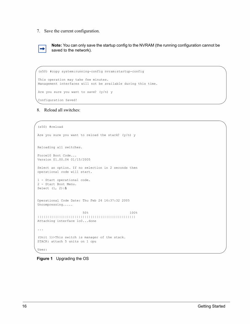
7. Save the current configuration.
8. Reload all switches:
Figure 1 Upgrading the OS
Note: You can only save the startup config to the NVRAM (the running configuration cannot be saved to the network).
(s50) #copy system:running-config nvram:startup-config
This operation may take few minutes.Management interfaces will not be available during this time.
Are you sure you want to save? (y/n) y
Configuration Saved!
(s50) #reload
Are you sure you want to reload the stack? (y/n) y
Reloading all switches.
Force10 Boot Code...Version 01.00.04 01/15/2005
Select an option. If no selection in 2 seconds thenoperational code will start.
1 - Start operational code.2 - Start Boot Menu.Select (1, 2):1
Operational Code Date: Thu Feb 24 16:37:32 2005Uncompressing.....
50% 100%||||||||||||||||||||||||||||||||||||||||||||||||||Attaching interface lo0...done
...
(Unit 1)>This switch is manager of the stack.STACK: attach 5 units on 1 cpu
User:
16 Getting Started

CLI Overview
Universal Access to Switch/router• Through a Console port:• Management Ethernet—Telnet, SSH
CLI Command Modes
As found in E-Series, the CLI Command mode are as follows:
• EXEC: (S50)>
• EXEC privilege: (S50) #
• CONFIGURATION: (S50) (conf)#
Here is an example navigating to these modes:
Getting Help From the CLI
The following help commands are the same as those found in E-Series:
• Use “?” at prompt.• Use “?” with partial command: “Force10# i?”• Use “?” after a command: “Force10# ip ?”
User Management• The default user, admin, has the following attributes Read/Write access.
(S50) >enablePassword:(S50) #configure(S50) (Config)#
SFTOS Configuration Guide, Version 2.1.4 17

Creating a User and PasswordBelow is an example screenshot of creating a user name and password:
Setting the Enable PasswordSetting the enable password must be executed from non-privileged mode:
:
Setting the HostnameThe following is a configuration example for setting the hostname:
Figure 2 Setting the Hostname
Note: The user has ReadOnly access for local login.
Note: The user has ReadOnly access for local login.
(S50) (Config)#users name student1(S50) (Config)#users passwd student1
Enter old password:
Enter new password:*******
Confirm new password:*******
Password Changed!
(Force10_S50) >enable passwdEnter new password:*******Confirm new password:*******Password Changed!
(F10_S50) #set prompt Force10_S50(Force10_S50) #
18 Getting Started

Creating a User and a PasswordThe following is a configuration example for creating a user and a password:
Figure 3 Creating a User and a Password
Showing Created UsersThe following is a configuration example for showing created users:
Figure 4 Showing Created Users
Clearing Running-configurationThe following is a configuration example for clearing the running configuration:
Figure 5 Clearing the Running Configuration
(Force10_S50) (Config)#users name cindy(Force10_S50) (Config)#users passwd cindyEnter old password:Enter new password:*****Confirm new password:*****Password Changed!
If there is no existing password, just press enter
(Force10_S50) #show user SNMPv3 SNMPv3 SNMPv3User Name User Access Mode Access Mode Authentication Encryption---------- ---------------- ----------- -------------- ----------admin Read/Write Read/Write None Nonecindy Read Only Read Only None NoneClear all users password(Force10_S50) #clear passAre you sure you want to reset all passwords? (y/n)yPasswords Reset!
(Force10_S50) #clear configAre you sure you want to clear the configuration? (y/n)yClearing configuration. Please wait for login rompt.(Force10_S50) #(Unit 1)>
SFTOS Configuration Guide, Version 2.1.4 19

Displaying Supported Features and System UptimeThe following is an example displaying all supported features and system uptime:
Figure 6 Displaying All Supported Features and System Uptime
(Force10 (S50) Routing) #show sysinfo
System Description............................. Force10 (S50) RoutingSystem Name....................................System Location................................System Contact.................................System Object ID............................... force10System Up Time................................. 0 days 4 hrs 9 mins 47 secs
MIBs Supported:
RFC 1907 - SNMPv2-MIB The MIB module for SNMPv2 entitiesRFC 2819 - RMON-MIB Remote Network Monitoring Management Information BaseFORCE10-REF-MIB Force10 Reference MIBSNMP-COMMUNITY-MIB This MIB module defines objects to help support coexistence between SNMPv1,SNMPv2, and SNMPv3.SNMP-FRAMEWORK-MIB The SNMP Management Architecture MIBSNMP-MPD-MIB The MIB for Message Processing and DispatchingSNMP-NOTIFICATION-MIB The Notification MIB ModuleSNMP-TARGET-MIB The Target MIB ModuleSNMP-USER-BASED-SM-MIB The management information definitions for the SNMP User-based Security Model.SNMP-VIEW-BASED-ACM-MIB The management information definitions for the View-based Access Control Model for SNMP.USM-TARGET-TAG-MIB SNMP Research, Inc.F10OS-POWER-ETHERNET-MIB F10OS Power Ethernet Extensions MIBPOWER-ETHERNET-MIB Power Ethernet MIBLAG-MIB The Link Aggregation module for managing IEEE 802.3adRFC 1213 - RFC1213-MIB Management Information Base for Network Management of TCP/IP-based internets: MIB-IIRFC 1493 - BRIDGE-MIB Definitions of Managed Objects for Bridges (dot1d)RFC 1643 - Etherlike-MIB Definitions of Managed Objects for the Ethernet-like Interface Types (dot3)RFC 2233 - IF-MIB The Interfaces Group MIB using SMIv2RFC 2674 - P-BRIDGE-MIB The Bridge MIB Extension module for managing Priority and Multicast Filtering, defined by IEEE 802.1D-1998.RFC 2674 - Q-BRIDGE-MIB The VLAN Bridge MIB module for managing Virtual Bridged Local Area NetworksRFC 2737 - ENTITY-MIB Entity MIB (Version 2)F10OS-SWITCHING-MIB F10OS Switching - Layer 2F10OS-INVENTORY-MIB F10OS Unit and Slot configuration.IEEE8021-PAE-MIB Port Access Entity module for managing IEEE 802.1X.F10OS-RADIUS-AUTH-CLIENT-MIB F10OS Radius MIBRADIUS-ACC-CLIENT-MIB RADIUS Accounting Client MIBRADIUS-AUTH-CLIENT-MIB RADIUS Authentication Client MIBF10OS-MGMT-SECURITY-MIB F10OS Private MIB for Management SecurityIANA-ADDRESS-FAMILY-NUMBERS-MIB The MIB module defines the AddressFamilyNumbers textual convention.RFC 1724 - RIPv2-MIB RIP Version 2 MIB ExtensionRFC 1850 - OSPF-MIB OSPF Version 2 Management Information BaseRFC 1850 - OSPF-TRAP-MIB The MIB module to describe traps for the OSPF Version 2 Protocol.RFC 2787 - VRRP-MIB Definitions of Managed Objects for the Virtual Router Redundancy ProtocolF10OS-ROUTING-MIB F10OS Routing - Layer 3F10OS-QOS-MIB F10OS Flex QOS Support
20 Getting Started

Verifying Switch Numbers and OS VersionThe following is a configuration example for verifying switch number and OS version:
Figure 7 Verifying Switch Number and OS Version
(Force10 (S50) Routing) #show switch
Management Preconfig Plugged-in Switch CodeSwitch Status Model ID Model ID Status Version------ ------------ ------------- ------------- --------------------- --------1 Mgmt Switch Force10 S-50 Force10 S-50 OK 1.1.5
(Force10_S50) #show switch 1Switch............................ 1Management Status................. Management SwitchHardware Management Preference.... UnassignedAdmin Management Preference....... UnassignedSwitch Type....................... 0x56950202Preconfigured Model Identifier.... Force10 S-50Plugged-in Model Identifier....... Force10 S-50Switch Status..................... OKSwitch Description................ Broadcom 5695 / 5675Expected Code Version............. 0.0.0.0Detected Code Version............. 1.1.5Detected Code in Flash............ 1.1.5Up Time........................... 0 days 0 hrs 11 mins 52 secs
SFTOS Configuration Guide, Version 2.1.4 21

Deleting Configuration File to Access System1. When system boots up
2. Select 2 to start Boot Menu
3. Select 10 to restore configuration to factory defaults (deletes configuration file)
Figure 8 Restoring Configuration to Factory Defaults
Read/Write Access Using SNMP V3The command users snmpv3 accessmode <username> <readonly | readwrite> and show user enables you to view read and write privileges on specific users:
Force10 Boot Code...Version 01.00.04 01/15/2005
Select an option. If no selection in 2 seconds thenoperational code will start.
1 - Start operational code.2 - Start Boot Menu.Select (1, 2):2
Boot Menu Version 01.00.04 01/15/2005
Options available1 - Start operational code2 - Change baud rate3 - Retrieve event log using XMODEM (64KB).4 - Load new operational code using XMODEM5 - Display operational code vital product data6 - Run Flash Diagnostics7 - Update Boot Code8 - Delete operational code9 - Reset the system10 - Restore Configuration to factory defaults (delete config files)[Boot Menu] 10
(S50) (Config)#users snmpv3 accessmode student2 readwrite(S50) #show user
SNMPv3 SNMPv3 SNMPv3User Name User Access Mode Access Mode Authentication Encryption---------- ---------------- ----------- -------------- ----------admin Read/Write Read/Write None Nonestudent1 Read Only Read Only None Nonestudent2 Read Only Read/Write None None
22 Getting Started

Port Naming ConventionThe port naming convention, “x/y/z”, designatesunit/slot/port. The physical entities that define this convention are as follows:
• Unit—one switch in a stack of switches (begins with the number 1).• Slot—slot numbers for physical entities (begin with number 0).• Port—physical interface (port numbers are sequential starting at 1 for each slot).
Logical entities are defined as follows:
• Also use unit/slot/port numbers• Unit numbers are a 0• Logical slot numbers
— Slot numbers are sequential and start with a 1• Logical interface numbers
— Interface numbers are sequential starting at 1 for each slot
VLAN Routing Interfaces, port-channels and LAGs are logical entities
Setting Network ParmsNetwork parms set the IP address of the switch and the gateway.
Note: This is done from privileged mode, not config mode.
(s50) #network parms 172.17.1.33 255.255.255.0 172.17.1.254
IP Adress of the Switch Mask Default Gateway
SFTOS Configuration Guide, Version 2.1.4 23

Showing Network SettingsUse the command show network to display network information such as IP address, Mask, Default Gateway, MAC information, etc. as shown below:
Resetting the Pre-configured SystemIf you are bringing up a system that had been previously configured in a stack, you must ensure the system is set to the correct unit number if installing into a new stack. If the system is not reconfigured to the correct unit number, it will come up as their switch number from the previous stack.
To ensure the unit comes up with the correct unit number in the new stack, use the switch renumber command to change the unit number.
Command Syntax Command Mode Purpose
switch oldunit renumber newunit EXEC This command changes the switch identifier for a switch in the stack. The oldunit is the current switch identifier on the switch whose identifier is to be changed. The newunit is the updated value of the switch identifier.
Note: When a switch unit is renumbered the "old" number is kept around as a detached unit until a 'no member' CLI is executed. Note: The RPC timeouts may happen when units are renumbered or management is moved from one unit to another unit.
(s50) #show network
IP Address..................................... 172.17.1.33Subnet Mask.................................... 255.255.255.0Default Gateway................................ 172.17.1.254Burned In MAC Address.......................... 00:03:E8:0D:20:00Locally Administered MAC Address............... 00:00:00:00:00:00MAC Address Type............................... Burned InNetwork Configuration Protocol Current......... NoneManagement VLAN ID............................. 1Web Mode....................................... DisableJava Mode...................................... Enable
24 Getting Started

Configuring an Interface with an IP AddressTo configure an UP address to an interface, use the following commands:
IP configuration takes precedence over VLAN configuration on a port. Therefore, configuring an IP Address and ‘routing’ on an interface, disables participation in VLANs on that interface.
Show IP Interface
Use the show ip interface command to display information:
Command Syntax Command Mode Purpose
ip routing GLOBAL Enables routing for an interface.
ip address INTERFACE Configures an IP address on an interface. The IP address may be a secondary IP address.
Note: You must configure ip routing at a global level, AND ‘routing’ at an interface level for you to be able to ping from, and to, the address.
Note: You must have the optional SFTOS Layer 3 software package installed to configure routing commands and to set IP addressing an interface.
(S50) #configure(S50) (Config)#ip routing(S50) (Config)#interface 1/0/3(S50) (Interface 1/0/3)#ip address 50.0.0.2 255.255.255.0(S50) (Interface 1/0/3)#routing
(S50) #show ip interface 1/0/3
IP Address..................................... 50.0.0.2Subnet Mask.................................... 255.255.255.0Routing Mode................................... EnableAdministrative Mode............................ EnableForward Net Directed Broadcasts................ DisableActive State................................... ActiveLink Speed Data Rate........................... 1000 FullMAC Address.................................... 00:03:E8:0D:20:01Encapsulation Type............................. EthernetIP Mtu......................................... 1500
(S50) #
SFTOS Configuration Guide, Version 2.1.4 25

Use the show ip interface brief command to display information.
Saving the Startup Config to the NetworkThe following is an example on how to save the startup configuration to a TFTP site on the network.
Setting Up a Management VLANThe following is an example on how to set up a management VLAN:
Note: It is possible to set the Management VLAN to a VLAN that doesn’t exist. If you can’t reach anything from the management address, check the mgmt_vlan with a show net or show run.
(S50) #show ip interface brief
Netdir MultiInterface IP Address IP Mask Bcast CastFwd--------- --------------- --------------- -------- --------1/0/3 50.0.0.2 255.255.255.0 Disable Disable1/0/4 66.1.1.1 255.255.255.0 Disable Disable
(S50) #
(s50) #copy nvram:startup-config tftp://172.16.1.56/s50_1
Mode........................................... TFTPSet TFTP Server IP............................. 172.16.1.56TFTP Path...................................... ./TFTP Filename.................................. s50_1Data Type...................................... Config File
Are you sure you want to start? (y/n) y
File transfer operation completed successfully.
(S50) #network mgmt_vlan 20
26 Getting Started

Important Points to Remember - VLANs• Default Management VLAN is 1 by default• By default ALL ports are members of VLAN 1 untagged• Command to change the Management VLAN ID
— (S50) #network mgmt_vlan 20
• It is possible to set the Management VLAN to a VLAN that doesn’t exist.• If you can’t reach anything from the management address, check the mgmt_vlan using show net or
show run.
Configuring from the NetworkThe following is an example of configuring from the network.
Important Points to Remember• The configuration file is binary• The configuration file is not human readable• Copies saved to the network are binary• You cannot cut and paste the configuration file • You can cut and paste show run output into a text file, and paste it in through Telnet or console
(S50) #copy tftp://172.16.1.56/s50_1 nvram:startup-config
Mode........................................... TFTPSet TFTP Server IP............................. 172.16.1.56TFTP Path...................................... ./TFTP Filename.................................. s50_1Data Type...................................... Config
Download configuration file. Current configuration will be cleared.
Are you sure you want to start? (y/n) yTFTP config transfer starting
TFTP download operation completed successfully.
(S50) #(Unit 1)>User:
You are now logged off
SFTOS Configuration Guide, Version 2.1.4 27
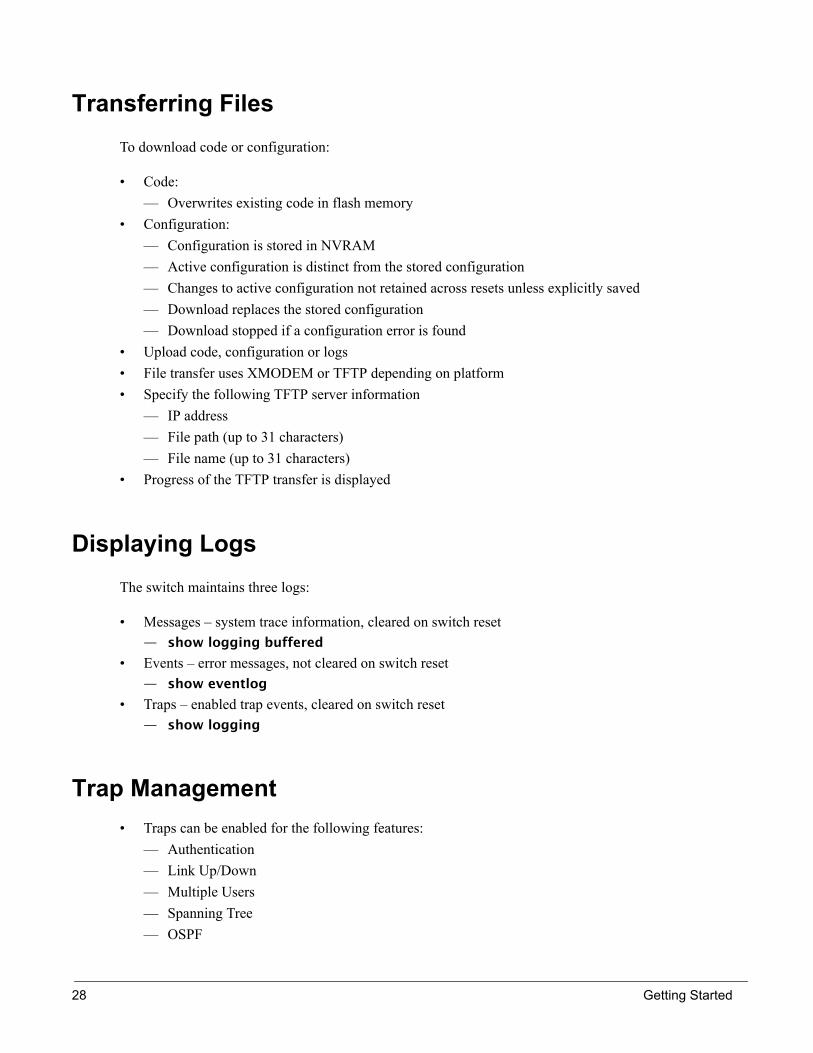
Transferring FilesTo download code or configuration:
• Code:— Overwrites existing code in flash memory
• Configuration: — Configuration is stored in NVRAM— Active configuration is distinct from the stored configuration— Changes to active configuration not retained across resets unless explicitly saved— Download replaces the stored configuration— Download stopped if a configuration error is found
• Upload code, configuration or logs• File transfer uses XMODEM or TFTP depending on platform• Specify the following TFTP server information
— IP address— File path (up to 31 characters)— File name (up to 31 characters)
• Progress of the TFTP transfer is displayed
Displaying LogsThe switch maintains three logs:
• Messages – system trace information, cleared on switch reset — show logging buffered
• Events – error messages, not cleared on switch reset— show eventlog
• Traps – enabled trap events, cleared on switch reset — show logging
Trap Management• Traps can be enabled for the following features:
— Authentication— Link Up/Down — Multiple Users— Spanning Tree— OSPF
28 Getting Started

— DVMRP— PIM (both DM and SM with one command)
• There is a separate set CLI commands, and one web screen.• Trap events are logged and sent out via SNMP
Trap Flags
Commands to [disable] enable traps are as follows:
global config node— [no] snmp-server enable traps— [no] snmp-server enable traps linkmode— [no] snmp-server enable traps bcaststorm— [no] snmp-server enable traps multiusers— [no] snmp-server enable traps stpmode— [no] ip dvmrp trapflags— [no] ip pim-trapflags
router OSPF config mode— [no] trapflags
display flags
This command is the Privileged Exec Mode command to display flags:
— show trapflags
Displaying StatisticsPrivileged Exec Mode commands to display statistics:
• Switch summary statistics:— show interface switchport
• Interface summary statistics:— show interface unit/slot/port
• Switch detailed statistics:— show interface ethernet switchport
• Interface detailed statistics:— show interface ethernet unit/slot/port
SFTOS Configuration Guide, Version 2.1.4 29
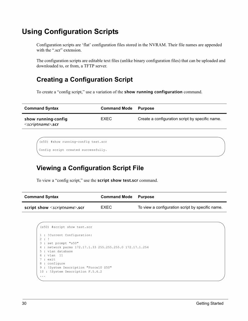
Using Configuration ScriptsConfiguration scripts are ‘flat’ configuration files stored in the NVRAM. Their file names are appended with the “.scr” extension.
The configuration scripts are editable text files (unlike binary configuration files) that can be uploaded and downloaded to, or from, a TFTP server.
Creating a Configuration Script
To create a “config script,” use a variation of the show running configuration command.
Viewing a Configuration Script File
To view a “config script,” use the script show test.scr command.
Command Syntax Command Mode Purpose
show running-config <scriptname>.scr
EXEC Create a configuration script by specific name.
Command Syntax Command Mode Purpose
script show <scriptname>.scr EXEC To view a configuration script by specific name.
(s50) #show running-config test.scr
Config script created successfully.
(s50) #script show test.scr
1 : !Current Configuration:2 : !3 : set prompt "s50"4 : network parms 172.17.1.33 255.255.255.0 172.17.1.2545 : vlan database6 : vlan 117 : exit8 : configure9 : !System Description "Force10 S50"10 : !System Description F.5.6.2...
30 Getting Started

Uploading a Configuration Script to a TFTP Server
To upload a “config script” to a TFTP server, use the copy command.
Deleting a Script
To delete a “config script”, use the script delete command.
Command Syntax Command Mode Purpose
copy nvram:script <scriptname.scr> tftp://x.x.x.x/<scriptname.scr>
EXEC Copies the config script from the NVRAM to a TFTP server.
Command Syntax Command Mode Purpose
script delete <scriptname.scr> EXEC
(s50) #copy nvram:script test.scr tftp://172.16.1.56/test.scr
Mode........................................... TFTPSet TFTP Server IP............................. 172.16.1.56TFTP Path......................................TFTP Filename.................................. test.scrData Type...................................... Config ScriptSource Filename................................ test.scr
Are you sure you want to start? (y/n) y
File transfer operation completed successfully.
(s50) #script delete test.scr
Are you sure you want to delete the configuration script(s)? (y/n)y
1 configuration script(s) deleted.
SFTOS Configuration Guide, Version 2.1.4 31

Downloading a Configuration Script from a TFTP Server
To download a “config script”, use the copy command as in the following.
Troubleshooting a Downloaded Script
While attempting to download a config script, the system validates the downloaded file. If the validation fails an error message like the following will appear:
Command Syntax Command Mode Purpose
copy tftp://x.x.x.x/scriptname.scr nvram:script scriptname.scr
EXEC To download a “config script” from a TFTP server.
(s50) #copy tftp://172.16.1.56/test.scr nvram:script test.scr
Mode........................................... TFTPSet TFTP Server IP............................. 172.16.1.56TFTP Path......................................TFTP Filename.................................. test.scrData Type...................................... Config ScriptDestination Filename........................... test.scr
Are you sure you want to start? (y/n) y
Validating configuration script...
set prompt "s50"
network parms 172.17.1.33 255.255.255.0 172.17.1.254
vlan database
vlan 11<output deleted>
Configuration script validation failed.Following lines in the script may have problem:Line 29:: permit 01:80:c2:00:00:00 any assign-queue 4Line 30:: permit any 01:80:c2:00:00:ff assign-queue 3 redirect 1/0/10Line 31:: permit 01:80:c2:00:00:ee any assign-queue 4Line 36:: match cos 5Line 44:: police-simple 500000 64 conform-action transmit violate-action dropLine 45:: police-simple 500000 64 conform-action transmit violate-action drop
Total error Lines :: 6The file being downloaded has potential problems. Do you want to save this file?
32 Getting Started
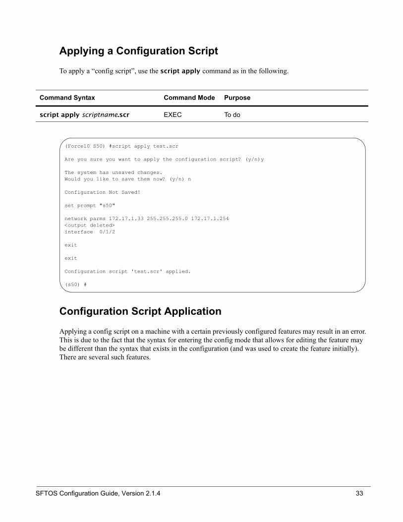
Applying a Configuration Script
To apply a “config script”, use the script apply command as in the following.
Configuration Script Application
Applying a config script on a machine with a certain previously configured features may result in an error. This is due to the fact that the syntax for entering the config mode that allows for editing the feature may be different than the syntax that exists in the configuration (and was used to create the feature initially). There are several such features.
Command Syntax Command Mode Purpose
script apply scriptname.scr EXEC To do
(Force10 S50) #script apply test.scr
Are you sure you want to apply the configuration script? (y/n)y
The system has unsaved changes.Would you like to save them now? (y/n) n
Configuration Not Saved!
set prompt "s50"
network parms 172.17.1.33 255.255.255.0 172.17.1.254<output deleted>interface 0/1/2
exit
exit
Configuration script 'test.scr' applied.
(s50) #
SFTOS Configuration Guide, Version 2.1.4 33

For example, to create a class-map called “cm-1” is class-map match-all cm-1. The command to edit cm-1 later is class-map cm-1. Attempting to apply an unmodified config script containing cm-1, to a machine that already has a class-map called cm-1, results in an error similar to the example below:
Failure to apply a config script can be resolved by one of the following solutions:
• Issuing the clear config command before applying the script.
• Editing the script to use the proper syntax to edit the structure (ACL, map etc.). • Editing the script by adding the no form of a command to delete a feature, then add a command to
reconfigure the same feature.
Listing Configuration Scripts
The following command lists the configured scripts in a system:
Note: Do not issue the clear configuration command if you Telnet into the system, otherwise you will lose contact with the system. This command should be issued at the Console port.
...class-map match-all cm-1This Diffserv class already exists.
Error in configuration script file at line number 33.CLI Command :: class-map match-all cm-1.Aborting script.Execution of configuration script 'test.scr' could not be completed.
WARNING: The running configuration may not be the desired configuration. You might want to reload the saved configuration....
(s50) #script list
Configuration Script Name Size(Bytes)-------------------------------- -----------test.scr 2689
1 configuration script(s) found.2045 Kbytes free.
(s50) #
34 Getting Started

Chapter 3 Supported Features(*) Denotes Pre-Production Feature
Table 1 Supported Features (NOTE: Layer 3 Package includes all features of Layer 2 Package)
Features Package Group
Hardware Features
48 GigE ports - Copper Layer 2
4 port SFP Shared GigE Layer 2
Optional 2 port 10GigE Uplink Layer 2
10/100/1000 port for management Layer 2
1 Serial Port Layer 2
Software Features Basic Routing and Switching
IPv4 (RFC 1812) Layer 3
CIDR (RFC 1519) Layer 3
IPv4 Router Discovery (RFC 1256) Layer 3
"BootP (RFC951, 1542) Layer 2
BOOTP/DHCP Relay and Server (RFC 2131) Layer 2
Host Requirements (RFC 1122) Layer 2
UDP (RFC 768) Layer 2
IP (RFC 791) Layer 2
ICMP (RFC 792) Layer 2
TCP (RFC 793) Layer 2
ARP (RFC 826) Layer 3
VRRP (RFC 2338) Layer 3
Spanning Tree Protocol (IEEE 802.1d) Layer 2
Rapid Spanning Tree (IEEE 802.1w) Layer 2
MSTP (IEEE 802.1s) Layer 2
SFTOS Configuration Guide, Version 2.1.4 35

Proxy ARP (RFC 1027) Layer 3
10 GigE (IEEE 802.3ae) Layer 2
1000 Base-T (IEEE 802.3ab) Layer 2
Flow Control (IEEE 802.3x) Layer 2
IEEE 802.3ad Layer 2
16k MAC Address table Layer 2
Jumbo Frame Support Layer 2
4k IPv4 Routing Table Entry Layer 3
QOS
Priority Queues Layer 2 (*)
Layer 2 classification Layer 2 (*)
802.1p priority marking Layer 2 (*)
Layer 3 DSCP Layer 2 (*)
Bandwidth based rate limiting Layer 2 (*)
Wirespeed ACLs (L2/L3/L4) Layer 2 (*)
ACL entries (L2 + L3) Layer 2 (*)
VLANS
Supported number of VLANs Layer 2
IEEE 802.1q support Layer 2
Port based VLANs Layer 2
Frame Extensions (IEEE 802.3ac) Layer 2 (*)
Protocol Based VLANs Layer 2 (*)
GVRP, GARP, GMRP Layer 2 (*)
Routing Protocol Support
RIPv1/v2 Layer 3
OSPF (RFC 2328, 1587, 1765, 2370) Layer 3
Static Routes Layer 3
Table 1 Supported Features (NOTE: Layer 3 Package includes all features of Layer 2 Package)
Features Package Group
36 Supported Features

Multicast Protocols
IGMP v1/v2 (RFC 1112, 2236) Layer 3
IGMP snooping Layer 2 (*)
PIM-SM-edge Layer 3
DVMRP Layer 3
PIM-DM Layer 3
Layer 2 Multicast forwarding Layer 2
Security & Packet Control Features
Ingress Rate Limiting Layer 2 (*)
Login Access Control Layer 2
RADIUS Layer 2
IEEE 802.1x Layer 2 (*)
SSH2 server support Layer 2 (*)
Port Mirroring Layer 2
Access Profiles on routing protocols Layer 2
DOS Protection Layer 2
MAC based port Security Layer 2 (*)
Management Features
Telnet (RFC 854) Layer 2
SSHv2 Layer 2
TFTP (RFC 783) Layer 2
Syslog Layer 2
SNMP v1/v2c Layer 2
RMON Groups Layer 2
HTML based management Layer 2
ECMP Layer 3
External redundant power system Layer 2
SNTP Layer 2
HTTPS/SSL Layer 2
Table 1 Supported Features (NOTE: Layer 3 Package includes all features of Layer 2 Package)
Features Package Group
SFTOS Configuration Guide, Version 2.1.4 37
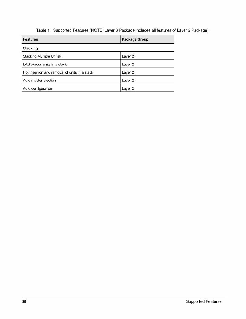
Stacking
Stacking Multiple Unitsk Layer 2
LAG across units in a stack Layer 2
Hot insertion and removal of units in a stack Layer 2
Auto master election Layer 2
Auto configuration Layer 2
Table 1 Supported Features (NOTE: Layer 3 Package includes all features of Layer 2 Package)
Features Package Group
38 Supported Features
This chapter displays sample configurations for the following management tasks using SFTOS:
• Creating the Management Port IP on page 39• Changing the Management VLAN from Default VLAN 1 on page 40• Verifying Management Port Network on page 40• Verifying Management Port Connectivity on page 40• Checking Interface Counters Per Port on page 41• Management Preferences on page 42• Unsetting Management Preference on page 42• Management Preference and MAC Address on page 42• Discovery Messages on page 43
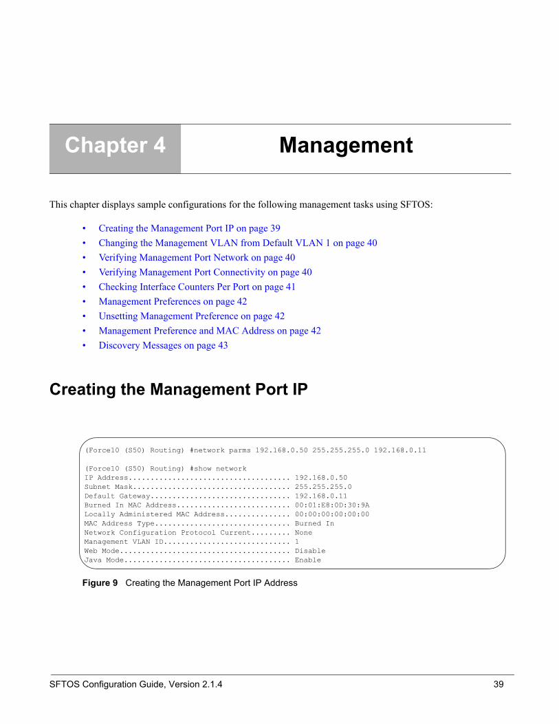
Creating the Management Port IP
Figure 9 Creating the Management Port IP Address
Chapter 4 Management
(Force10 (S50) Routing) #network parms 192.168.0.50 255.255.255.0 192.168.0.11
(Force10 (S50) Routing) #show networkIP Address..................................... 192.168.0.50Subnet Mask.................................... 255.255.255.0Default Gateway................................ 192.168.0.11Burned In MAC Address.......................... 00:01:E8:0D:30:9ALocally Administered MAC Address............... 00:00:00:00:00:00MAC Address Type............................... Burned InNetwork Configuration Protocol Current......... NoneManagement VLAN ID............................. 1Web Mode....................................... DisableJava Mode...................................... Enable
SFTOS Configuration Guide, Version 2.1.4 39

Changing the Management VLAN from Default VLAN 1
Figure 10 Changing Management VLAN from Default
Verifying Management Port Network
Figure 11 Verifying Management Port Network
Verifying Management Port Connectivity
Figure 12 Verifying Management Port Connectivity
network mgmt_vlan 5vlan databasevlan 5vlan name 5 "management_vlan“
interface 1/0/43vlan pvid 5vlan ingressfiltervlan participation exclude 1vlan participation include 5exit
(Force10 (S50) Routing) #show network
IP Address..................................... 192.168.0.50Subnet Mask.................................... 255.255.255.0Default Gateway................................ 192.168.0.11Burned In MAC Address.......................... 00:01:E8:0D:30:9ALocally Administered MAC Address............... 00:00:00:00:00:00MAC Address Type............................... Burned InNetwork Configuration Protocol Current......... NoneManagement VLAN ID............................. 5Web Mode....................................... DisableJava Mode...................................... Enable
(Force10 (S50) Routing) #ping 192.168.0.100Send count=3, Receive count=3 from 192.168.0.100 Verify management port connectivity
40 Management

Checking Interface Counters Per Port
Figure 13 Checking Interface Counters Per Port
(Force10 (S50) Routing) #show interface ethernet 1/0/43
Total Packets Received (Octets)................ 16217658Packets Received > 1522 Octets................. 0Packets RX and TX 64 Octets.................... 3260Packets RX and TX 65-127 Octets................ 11968Packets RX and TX 128-255 Octets............... 6329Packets RX and TX 256-511 Octets............... 4812Packets RX and TX 512-1023 Octets.............. 338Packets RX and TX 1024-1518 Octets............. 7710Packets RX and TX 1519-1522 Octets............. 0Packets RX and TX 1523-2047 Octets............. 0Packets RX and TX 2048-4095 Octets............. 0Packets RX and TX 4096-9216 Octets............. 0
Total Packets Received Without Errors.......... 34091Unicast Packets Received....................... 30641Multicast Packets Received..................... 2010Broadcast Packets Received..................... 1440Total Packets Received with MAC Errors......... 0Jabbers Received............................... 0Fragments/Undersize Received................... 0Alignment Errors............................... 0--More-- or (q)uitFCS Errors..................................... 0Overruns....................................... 0
Total Received Packets Not Forwarded........... 0Local Traffic Frames........................... 0802.3x Pause Frames Received................... 0Unacceptable Frame Type........................ 0Multicast Tree Viable Discards................. 0Reserved Address Discards...................... 0Broadcast Storm Recovery....................... 0CFI Discards................................... 0Upstream Threshold............................. 0
Total Packets Transmitted (Octets)............. 52084Max Frame Size................................. 1518
Total Packets Transmitted Successfully......... 326Unicast Packets Transmitted.................... 105Multicast Packets Transmitted.................. 0Broadcast Packets Transmitted.................. 221Total Transmit Errors.......................... 0FCS Errors..................................... 0--More-- or (q)uitTx Oversized................................... 0Underrun Errors................................ 0
Total Transmit Packets Discarded............... 0Single Collision Frames........................ 0Multiple Collision Frames...................... 0Excessive Collision Frames..................... 0Port Membership Discards....................... 0
802.3x Pause Frames Transmitted................ 0GVRP PDUs received............................. 0GVRP PDUs Transmitted.......................... 0GVRP Failed Registrations...................... 0GMRP PDUs Received............................. 0GMRP PDUs Transmitted.......................... 0GMRP Failed Registrations...................... 0
STP BPDUs Transmitted.......................... 0STP BPDUs Received............................. 0RSTP BPDUs Transmitted......................... 0RSTP BPDUs Received............................ 0MSTP BPDUs Transmitted......................... 0MSTP BPDUs Received............................ 0--More-- or (q)uit
EAPOL Frames Transmitted....................... 0EAPOL Start Frames Received.................... 0
Time Since Counters Last Cleared............... 0 day 5 hr 7 min 16 sec
SFTOS Configuration Guide, Version 2.1.4 41

Management PreferencesThe command show switch number displays a field called "Hardware Management Preference" and one called “Admin Management Preferences.” The attribute for “Hardware Management Preferences” cannot be changed through the CLI. The attribute for “Admin Management Preferences” can be changed through the command switch number priority value.
Hardware Management Preference
The “Hardware Management Preference” field indicates whether the device is capable of becoming a management unit. The value for “Hardware Management Preference” always displays as “Unassigned.” The valid values for this field are “Disabled” and “Unassigned” (default).
Administrative Management Preference
The “Administrative Management Preference” indicates the preference given to this unit over another units by an administrator when the management unit fails. The default value is “1.” A value of “0” means the unit cannot become a management unit.
This field indicates the administrative management preference value assigned to the switch. This preference value indicates how likely the switch is to be chosen as the Primary Management Unit.
Unsetting Management PreferenceThere is no CLI command to set management preference back to “unassigned”. The management preference information is stored locally on each box, and can be erased using the boot menu option that deletes all configuration files including the unit number.
Management Preference and MAC AddressThe role of each switch in a stack as either manager or member can be changed by setting the management preference and MAC address. Management preference is considered before the MAC address. The higher the management preference value is makes it more likely for that switch to become manager. Likewise, the higher the MAC address value is makes it more likely for that switch to become manager.
The preference decision is made only when the current manager fails and a new manager needs to be selected, or when a stack of units is powered up with none of the units previously holding the management role. If two managers are connected together, then management preference has no effect.
42 Management

Discovery MessagesThe command devshell ut(10) is used to check discovery messages exchanged between switches in a stack. The ut(10) parameter indicates how many messages you wish to see. The command can be issued on the manager and stack units.
SFTOS Configuration Guide, Version 2.1.4 43

44 Management

This chapter documents the following SFTOS stackability features:
• Stackability Features on page 45• Important Points to Remember on page 46• Management Unit Selection Algorithm on page 46• Unit Number Assignment on page 46• Stackability Commands on page 47
Stackability Features• Stacking cable length availability
— Short Length stacking cable (60 cm)— Long Length stacking cable (4 meters)
• Stack manager selection algorithm• Stacking commands
How to connect each S50 with stacking cables:
Figure 14 Stacking Cabling Methods
Chapter 5 Stackability
A BSwitch 1
A BSwitch 2
A BSwitch 3
Ring Connection Cascade Connection
A BSwitch 1
A BSwitch 2
A BSwitch 3
A BSwitch 4
SFTOS Configuration Guide, Version 2.1.4 45

Important Points to Remember• Manage the whole stack unit as a single unit.• In current release, each switch need to have the same OS version.• Issue CLI command at the management unit only.• Upgrading the stack manager automatically upgrades other units in the stack.• Configuration and Images can be distributed to all units from the Management unit.
Management Unit Selection Algorithm• If the unit is configured to be a Management Unit, but another Management Unit is already active, then
the unit changes its configured value to disable the Primary Management Unit function.• If the Management Unit function is unassigned and there is another Management Unit in the system
then the unit changes its configured value to disable the Primary Management Unit function.• If the Management Unit function is enabled or unassigned and there is no other Primary Management
unit in the system, then the unit becomes the Primary Management Unit.• If the Primary Management Unit function is disabled then the unit remains a non-primary management
unit.• The priority is only used to select the next manager when the current manager fails.• In the case when two units come up at the same time, then whichever has the higher priority or higher
MAC address becomes the management unit• The last Management Unit has the highest preference for becoming the manager after a reboot.
Unit Number Assignment• If the unit number is configured, but another unit already uses that number, the unit changes its
configured unit number to the lowest unassigned unit number.• If the unit number is unassigned then the unit sets its configured unit number to the lowest unassigned
unit number.• If the unit number is configured and no other device uses the unit number, then the unit starts using the
configured unit number.• If a unit detects the maximum number of units already exist, the unit sets its unit number to
"unassigned“ and stays in the Initialization state.
46 Stackability

Stackability CommandsThe following are the stacking commands:
Command Syntax Command Mode Purpose
show switch Privileged mode This command displays information about all units in the stack.
show switch <unit> Privileged mode This command displays information for a specific unit in the stack.
show supported switchtype Privileged mode This commands displays information about all supported switch types.
show supported switchtype <switchindex>
Privileged mode This commands displays information about a requested switch type.
stack Global Config Enables user to enter Config-stack mode.
switch <oldunit> renumber <newunit>
Config mode This command changes the switch identifier for a switch in the stack.
switch <unit> priority <value> Config mode This command configures the ability of a switch to become the Primary Management Unit.
[no] member <unit> <switchindex>
Stack Global Config
This command configures a switch. The unit is the switch identifier of the switch to be added/removed from the stack. The switchindex (SID) is the index into the database of the supported switch types, indicating the type of the switch being preconfigured.
movemanagement <fromunit> <tounit>
Stack Global Config
This command moves the Primary Management Unit functionality from one switch to another.
archive copy-sw <destination-system <unit>>
Stack Global Config
This command replicates the STK file from the Primary Management Unit to the other switch(es) in the stack.
archive download-sw <url> Stack Global Config
This command downloads the STK file to the switch.
SFTOS Configuration Guide, Version 2.1.4 47

To show information about MAC addresses in a stack, use the show mac-addr-table command:
Figure 15 show switch Command Example
To show information about port status in a stack, use the show stack-port command:
Figure 16 show stack-port Command Example
(Force10 S50) #show mac-addr-tableMac Address Interface IfIndex Status ----------------------- --------- ------- ------------00:01:00:01:00:00:00:01 2/0/37 87 Learned 00:01:00:01:00:00:00:37 1/0/1 1 Learned 00:01:00:03:00:00:00:03 1/0/2 2 Learned 00:01:00:03:00:00:00:39 2/0/38 88 Learned 00:01:00:04:00:00:00:45 2/0/45 95 Learned 00:01:00:04:00:00:00:46 1/0/45 45 Learned 00:01:00:06:00:00:00:47 2/0/46 96 Learned 00:01:00:06:00:00:00:48 1/0/46 46 Learned 00:01:00:D0:95:B7:CD:2E 0/3/1 401 Management
(Force10 S50) #show stack-portConfigured Running Stack Stack Link LinkUnit Interface Mode Mode Status Speed (Gb/s)---- ---------------- ---------- ---------- ------------ ------------1 HiGig 1 N/A Stack Link Up 10 1 HiGig 2 N/A Stack Link Down 10 2 HiGig 1 N/A Stack Link Down 10 2 HiGig 2 N/A Stack Link Up 10 3 HiGig 1 N/A Stack Link Up 10 3 HiGig 2 N/A Stack Link Up 10
48 Stackability

For a summary of all the units in a stack, use the show switch command:
Figure 17 show switch Command Example
To add a unit to the stack, use the member command:
Figure 18 Using the member Command to Add a Unit
(Force10 S50) #show switch
Management Preconfig Plugged-in Switch Code Switch Status Model ID Model ID Status Version------ ------------ ------------- ------------- --------------------- --------1 Mgmt Switch SA-01-GE-48T SA-01-GE-48T OK F.4.21 3 Stack Member SA-01-GE-48T SA-01-GE-48T OK F.4.21 4 Stack Member SA-01-GE-48T SA-01-GE-48T OK F.4.21
(Force10 S50) #show switch 1
Switch............................ 1Management Status................. Management SwitchHardware Management Preference.... UnassignedAdmin Management Preference....... UnassignedSwitch Type....................... 0x56950202Preconfigured Model Identifier.... SA-01-GE-48TPlugged-in Model Identifier....... SA-01-GE-48TSwitch Status..................... OKSwitch Description................ Expected Code Type................ 0x100b000Detected Code Version............. F.4.21Detected Code in Flash............ F.4.21Serial Number..................... DE40047Up Time........................... 0 days 0 hrs 33 mins 55 secs
Stack ManagerMemberMember
(Force10 S50) #show supported switchtype
Mgmt CodeSID Switch Model ID Pref Type--- -------------------------------- ------------ ---------1 SA-01-GE-48T 1 0x100b0002 SA-01-GE-48T 1 0x100b000
(Force10 S50) #configure (Force10 S50) (Config)#stack (Force10 S50) (config-stack)#member 5 1(Force10 S50) (config-stack)#exit(Force10 S50) (Config)#exit(Force10 S50) #show switch
Management Preconfig Plugged-in Switch Code Switch Status Model ID Model ID Status Version------ ------------ ------------- ------------- --------------------- --------1 Mgmt Switch SA-01-GE-48T SA-01-GE-48T OK F.4.21 3 Stack Member SA-01-GE-48T SA-01-GE-48T OK F.4.21 4 Stack Member SA-01-GE-48T SA-01-GE-48T OK F.4.21 5 Unassigned SA-01-GE-48T Not Present 0.0.0
(Force10 S50) #
Unit 5 added
SFTOS Configuration Guide, Version 2.1.4 49

To remove a unit from the stack, use the member command:
Figure 19 Using the member Command to Remove a Unit
(Force10 S50) (config-stack)#no member 5(Force10 S50) (config-stack)#exit(Force10 S50) (Config)#exit(Force10 S50) #show switch
Management Preconfig Plugged-in Switch Code Switch Status Model ID Model ID Status Version------ ------------ ------------- ------------- --------------------- --------1 Mgmt Switch SA-01-GE-48T SA-01-GE-48T OK F.4.21 3 Stack Member SA-01-GE-48T SA-01-GE-48T OK F.4.21 4 Stack Member SA-01-GE-48T SA-01-GE-48T OK F.4.21
(Force10 S50) #Unit 5 removed
50 Stackability
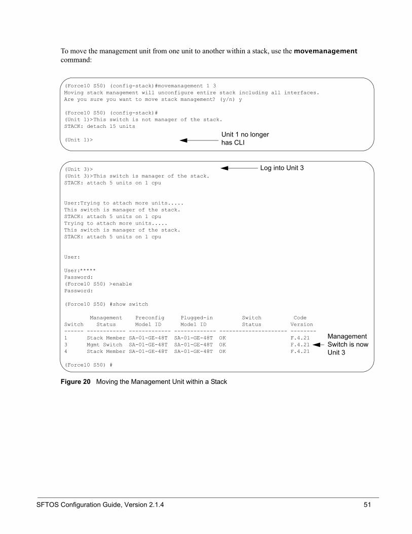
To move the management unit from one unit to another within a stack, use the movemanagement command:
Figure 20 Moving the Management Unit within a Stack
(Unit 3)>(Unit 3)>This switch is manager of the stack.STACK: attach 5 units on 1 cpu
User:Trying to attach more units.....This switch is manager of the stack.STACK: attach 5 units on 1 cpuTrying to attach more units.....This switch is manager of the stack.STACK: attach 5 units on 1 cpu
User:
User:*****Password:(Force10 S50) >enablePassword:
(Force10 S50) #show switch
Management Preconfig Plugged-in Switch CodeSwitch Status Model ID Model ID Status Version------ ------------ ------------- ------------- --------------------- --------1 Stack Member SA-01-GE-48T SA-01-GE-48T OK F.4.213 Mgmt Switch SA-01-GE-48T SA-01-GE-48T OK F.4.214 Stack Member SA-01-GE-48T SA-01-GE-48T OK F.4.21
(Force10 S50) #
Management Switch is now Unit 3
(Force10 S50) (config-stack)#movemanagement 1 3Moving stack management will unconfigure entire stack including all interfaces.Are you sure you want to move stack management? (y/n) y
(Force10 S50) (config-stack)#(Unit 1)>This switch is not manager of the stack.STACK: detach 15 units
(Unit 1)>Unit 1 no longer has CLI
Log into Unit 3
SFTOS Configuration Guide, Version 2.1.4 51

To change the priority of a switch within a stack, use the switch <unit> priority <value> command:
Figure 21 Changing Switch Unit Priority
(Force10 S50) (Config)#switch 4 priority 2(Force10 S50) (Config)#exit(Force10 S50) #show switch
Management Preconfig Plugged-in Switch Code Switch Status Model ID Model ID Status Version------ ------------ ------------- ------------- --------------------- --------1 Stack Member SA-01-GE-48T SA-01-GE-48T OK F.4.21 3 Mgmt Switch SA-01-GE-48T SA-01-GE-48T OK F.4.21 4 Stack Member SA-01-GE-48T SA-01-GE-48T OK F.4.21
(Force10 S50) #show switch 3 4
Switch............................ 4Management Status................. Stack MemberHardware Management Preference.... UnassignedAdmin Management Preference....... 2Switch Type....................... 0x56950202Preconfigured Model Identifier.... SA-01-GE-48TPlugged-in Model Identifier....... SA-01-GE-48TSwitch Status..................... OKSwitch Description................ Expected Code Type................ 0x100b000Detected Code Version............. F.4.21Detected Code in Flash............ F.4.21Serial Number..................... DE40034!Up Time........................... 0 days 0 hrs 56 mins 51 secs
Value is now set to priority 2
52 Stackability

SFTOS supports the following features:
• Switching Features on page 53• Forwarding, Aging, and Learning on page 53• Spanning Tree Protocol (IEEE 802.1d) on page 54• Forceversion Command on page 54• Multiple Spanning-Tree Protocol (MSTP, IEEE 802.1s) on page 64
Switching Features• Switching applications and protocols, including:• Forwarding, Aging and Learning• Spanning Tree, IVL and STP per VLAN• IEEE 802.1d Spanning Tree• IEEE 802.1w Rapid Spanning Tree• IEEE 802.1s Multiple Spanning Tree
Forwarding, Aging, and Learning• Forwarding
— At layer 2, frames are forwarded according to their MAC address• Aging
— SFTOS supports a user-configurable address aging timeout parameter as defined in IEEE 802.1d • Learning
— SFTOS learns and manages MAC addresses as specified in IEEE 802.1d and IEEE 802.1q— SFTOS supports Shared VLAN Learning (SVL) although Independent VLAN Learning (IVL) is
the default
Chapter 6 Spanning Tree and MSTP
SFTOS Configuration Guide, Version 2.1.4 53
Spanning Tree Protocol (IEEE 802.1d)STP uses a spanning tree algorithm to provide path redundancy while preventing undesirable loops in a network.
• SFTOS switching can be configured to run with STP enabled or disabled.• Without STP, a path failure causes a loss of connectivity.• STP allows only one active path at a time between any two network devices, but allows for backup
paths.• When a topology change occurs, accelerated aging is used on the forwarding database(s).
SFTOS Spanning-Tree Protocol (STP) conforms to IEEE 802.1D and RFC 1493 Bridge MIB. STP allows port costs to be configured as zero, which causes the port to use IEEE 802.1D-recommended values. In addition, per-port Administrative Mode affects sequence when link comes up:
• IEEE 802.1D mode—follows the standard.• Fast mode—listening and learning timers set to two seconds (this is recommended to avoid time-outs
during reconfiguration).• Off/manual mode—port is always in forwarding mode (this is recommended, but only when no loops
are possible).
Forceversion CommandThe Global Configuration command spanning-tree forceversion sets the protocol Version parameter to a new value. The Force Protocol Version can be one of the following:
• 802.1d - STP BPDUs are transmitted rather than MST BPDUs (IEEE 802.1d functionality supported)• 802.1w - RST BPDUs are transmitted rather than MST BPDUs (IEEE 802.1w functionality supported)• 802.1s - MST BPDUs are transmitted (IEEE 802.1s functionality supported)
— spanning-tree forceversion <802.1d | 802.1w | 802.1s>
CLI Management
Privileged and User Exec Mode CLI commands:
• Display STP settings and parameters for the switch— show spanning-tree summary
• Display STP settings and parameters for the bridge instance— show spanning-tree [brief]
Global Config Mode CLI commands:
• [Disable] enable spanning tree for the switch:
54 Spanning Tree and MSTP

— [no] spanning-tree
• Set maximum time for discarding STP configuration messages, default 20 seconds— [no] spanning-tree max-age <6-40>
• Set time between STP config messages, default 2 seconds— [no] spanning-tree hellotime <1-10>
• Set time spent in listening and learning, default 15 seconds— [no] spanning-tree forward-times <4-30>
CLI Port Management
Privileged and User Exec Mode CLI command:
• Display STP settings and parameters for an interface— show spanning-tree interface <unit/slot/port>
Global Config Mode CLI command:
• [Disable] enable STP administrative mode for all interfaces— [no] spanning-tree port mode all
Interface Config Mode CLI command:
• [Disable] enable STP administrative mode for an interface— [no] spanning-tree port mode
Configuration Example
STP: (default FP STP disable, edge port disable)
• no edge port is used for switch to switch• Switch 2 is used for switching.• Switch1 is the root bridge.• If using spanning-tree forceversion 802.1w to change the protocol, then, when this switch
changes back to 802.1s, its peers has to use spanning-tree bpdumigrationcheck all to initialize their own protocol. Or just reset the peers.— For instance, when Switch 2 runs spanning-tree forceversion 802.1w, Switch 1 and Switch 3
will auto adjust their protocols to 802.1w. When Switch 2 reconfigures back to 802.1s (spanning-tree forceversion 802.1s), Switch 1 and Switch 3 must run spanning-tree bpdumigrationcheck all.
Procedure1.Configure the STP switch using below CLI2.Check the STP status
SFTOS Configuration Guide, Version 2.1.4 55

3.Set Switch 2 forceversion 802.1w4.Verify the STP status
Verify• show spanning-tree
• show spanning-tree mst port summary 0 all
• show spanning-tree mst port detailed 0/0/3
Switch2_r421:
vlan database vlan routing 1exit
set prompt Switch2_r421remotecon timeout 0
config lineconfig serial timeout 0 exit
spanning-tree spanning-tree port mode all
int 0/1 no span edge exit int 0/3 no span edge exit exit
config spanning-tree forceversion 802.1w
56 Spanning Tree and MSTP

Switch1_A_H2 : (use port 0/1 and 0/12)
Switch3_5615_H2 : (use port 0/3 & 0/12)
vlan database vlan routing 1exit
set prompt Switch1_A_H2remotecon timeout 0
config lineconfig serial timeout 0 exit
spanning-tree spanning-tree port mode all
int 0/1 no span edge exit
int 0/12 no span edge exit exit
*Switch1 is rootconfig spanning-tree mst priority 0 30000
vlan database vlan routing 1exit
set prompt Switch3_5615_H2remotecon timeout 0
config lineconfig serial timeout 0 exit
spanning-tree spanning-tree port mode all
int 0/3 no span edge exit int 0/12 no span edge exit exit
SFTOS Configuration Guide, Version 2.1.4 57
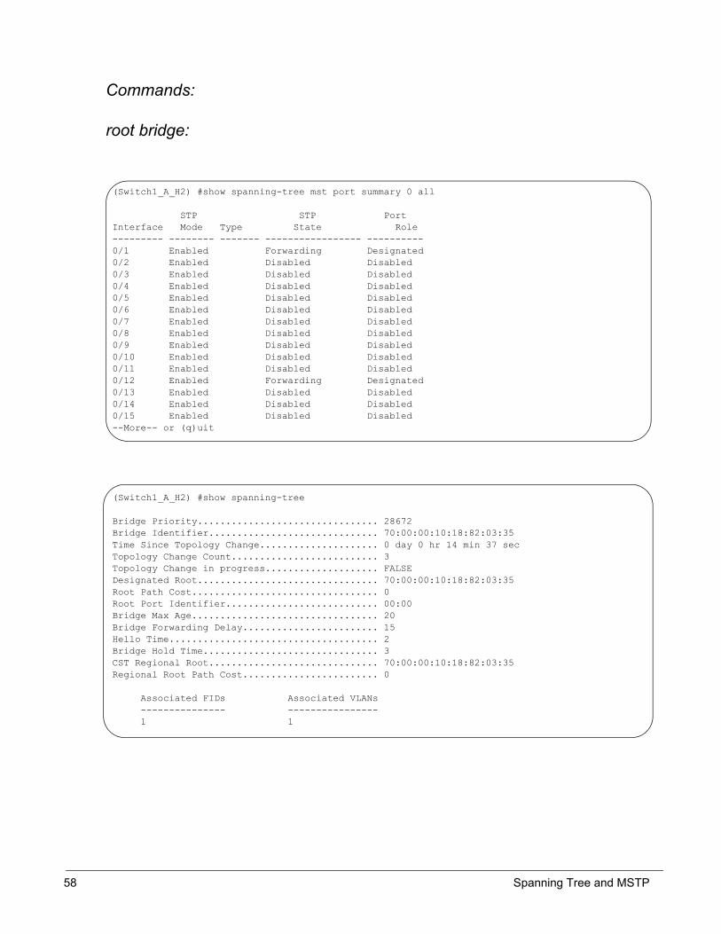
Commands:
root bridge:
(Switch1_A_H2) #show spanning-tree mst port summary 0 all
STP STP PortInterface Mode Type State Role--------- -------- ------- ----------------- ----------0/1 Enabled Forwarding Designated0/2 Enabled Disabled Disabled0/3 Enabled Disabled Disabled0/4 Enabled Disabled Disabled0/5 Enabled Disabled Disabled0/6 Enabled Disabled Disabled0/7 Enabled Disabled Disabled0/8 Enabled Disabled Disabled0/9 Enabled Disabled Disabled0/10 Enabled Disabled Disabled0/11 Enabled Disabled Disabled0/12 Enabled Forwarding Designated0/13 Enabled Disabled Disabled0/14 Enabled Disabled Disabled0/15 Enabled Disabled Disabled--More-- or (q)uit
(Switch1_A_H2) #show spanning-tree
Bridge Priority................................ 28672Bridge Identifier.............................. 70:00:00:10:18:82:03:35Time Since Topology Change..................... 0 day 0 hr 14 min 37 secTopology Change Count.......................... 3Topology Change in progress.................... FALSEDesignated Root................................ 70:00:00:10:18:82:03:35Root Path Cost................................. 0Root Port Identifier........................... 00:00Bridge Max Age................................. 20Bridge Forwarding Delay........................ 15Hello Time..................................... 2Bridge Hold Time............................... 3CST Regional Root.............................. 70:00:00:10:18:82:03:35Regional Root Path Cost........................ 0
Associated FIDs Associated VLANs --------------- ---------------- 1 1
58 Spanning Tree and MSTP

switch2:
(Switch2_r421) #show spanning-tree
Bridge Priority................................ 32768Bridge Identifier.............................. 80:00:00:10:18:82:02:CATime Since Topology Change..................... 0 day 0 hr 0 min 4 secTopology Change Count.......................... 0Topology Change in progress.................... FALSEDesignated Root................................ 80:00:00:10:18:82:02:CARoot Path Cost................................. 0Root Port Identifier........................... 00:00Bridge Max Age................................. 20Bridge Forwarding Delay........................ 15Hello Time..................................... 2Bridge Hold Time............................... 3CST Regional Root.............................. 80:00:00:10:18:82:02:CARegional Root Path Cost........................ 0
Associated FIDs Associated VLANs --------------- ---------------- 1 1
(Switch2_r421) #show spanning-tree
Bridge Priority................................ 32768Bridge Identifier.............................. 80:00:00:10:18:82:02:CATime Since Topology Change..................... 0 day 0 hr 1 min 12 secTopology Change Count.......................... 4Topology Change in progress.................... FALSEDesignated Root................................ 70:00:00:10:18:82:03:35Root Path Cost................................. 200000Root Port Identifier........................... 80:03Bridge Max Age................................. 20Bridge Forwarding Delay........................ 15Hello Time..................................... 2Bridge Hold Time............................... 3CST Regional Root.............................. 80:00:00:10:18:82:02:CARegional Root Path Cost........................ 0
Associated FIDs Associated VLANs --------------- ---------------- 1 1
SFTOS Configuration Guide, Version 2.1.4 59
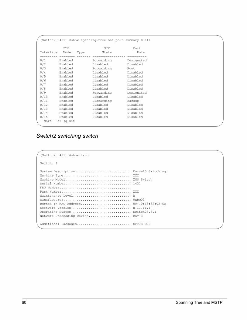
Switch2 switching switch
(Switch2_r421) #show spanning-tree mst port summary 0 all
STP STP PortInterface Mode Type State Role--------- -------- ------- ----------------- ----------0/1 Enabled Forwarding Designated0/2 Enabled Disabled Disabled0/3 Enabled Forwarding Root0/4 Enabled Disabled Disabled0/5 Enabled Disabled Disabled0/6 Enabled Disabled Disabled0/7 Enabled Disabled Disabled0/8 Enabled Disabled Disabled0/9 Enabled Forwarding Designated0/10 Enabled Disabled Disabled0/11 Enabled Discarding Backup0/12 Enabled Disabled Disabled0/13 Enabled Disabled Disabled0/14 Enabled Disabled Disabled0/15 Enabled Disabled Disabled--More-- or (q)uit
(Switch2_r421) #show hard
Switch: 1
System Description............................. Force10 SwitchingMachine Type................................... XXXMachine Model.................................. XGS SwitchSerial Number.................................. 1431FRU Number.....................................Part Number.................................... XXXMaintenance Level.............................. AManufacturer................................... 0xbc00Burned In MAC Address.......................... 00:10:18:82:02:CASoftware Version............................... H.11.11.1Operating System............................... Switch25.5.1Network Processing Device...................... REV 3
Additional Packages............................ SFTOS QOS
60 Spanning Tree and MSTP

(Switch2_r421) (Config)#spanning-tree forceversion 802.1w(Switch2_r421) #show span
Bridge Priority................................ 32768Bridge Identifier.............................. 80:00:00:10:18:82:02:CATime Since Topology Change..................... 0 day 0 hr 10 min 12 secTopology Change Count.......................... 5Topology Change in progress.................... FALSEDesignated Root................................ 70:00:00:10:18:82:03:35Root Path Cost................................. 200000Root Port Identifier........................... 80:03Bridge Max Age................................. 20Bridge Forwarding Delay........................ 15Hello Time..................................... 2Bridge Hold Time............................... 3CST Regional Root.............................. 80:00:00:10:18:82:02:CARegional Root Path Cost........................ 0
Associated FIDs Associated VLANs --------------- ---------------- 1 1
(Switch2_r421) #show spanning-tree
Bridge Priority................................ 32768Bridge Identifier.............................. 80:00:00:10:18:82:02:CATime Since Topology Change..................... 0 day 0 hr 10 min 29 secTopology Change Count.......................... 5Topology Change in progress.................... FALSEDesignated Root................................ 70:00:00:10:18:82:03:35Root Path Cost................................. 200000Root Port Identifier........................... 80:03Bridge Max Age................................. 20Bridge Forwarding Delay........................ 15Hello Time..................................... 2Bridge Hold Time............................... 3CST Regional Root.............................. 80:00:00:10:18:82:02:CARegional Root Path Cost........................ 0
Associated FIDs Associated VLANs --------------- ---------------- 1 1
SFTOS Configuration Guide, Version 2.1.4 61

(Switch2_r421) #show spanning-tree mst port detailed 0 0/3
Port Identifier................................ 80:03Port Priority.................................. 128Port Forwarding State.......................... ForwardingPort Role...................................... RootAuto-calculate Port Path Cost.................. EnabledPort Path Cost................................. 200000Designated Root................................ 70:00:00:10:18:82:03:35Designated Port Cost........................... 0Designated Bridge.............................. 70:00:00:10:18:82:03:35Designated Port Identifier..................... 80:01Topology Change Acknowledge.................... FALSEHello Time..................................... 2Edge Port...................................... FALSEEdge Port Status............................... FALSEPoint to Point MAC Status...................... TRUECST Regional Root.............................. 70:00:00:10:18:82:03:35CST Path Cost.................................. 0
(Switch2_r421) #show spanning-tree mst port detailed 0 0/1
Port Identifier................................ 80:01Port Priority.................................. 128Port Forwarding State.......................... ForwardingPort Role...................................... DesignatedAuto-calculate Port Path Cost.................. EnabledPort Path Cost................................. 200000Designated Root................................ 70:00:00:10:18:82:03:35Designated Port Cost........................... 200000Designated Bridge.............................. 80:00:00:10:18:82:02:CADesignated Port Identifier..................... 80:01Topology Change Acknowledge.................... FALSEHello Time..................................... 2Edge Port...................................... FALSEEdge Port Status............................... FALSEPoint to Point MAC Status...................... TRUECST Regional Root.............................. 80:00:00:10:18:82:02:CACST Path Cost.................................. 0
62 Spanning Tree and MSTP

802.1w
(Switch2_r421) #show spanning-tree mst port detailed 0 0/9
Port Identifier................................ 80:09Port Priority.................................. 128Port Forwarding State.......................... ForwardingPort Role...................................... DesignatedAuto-calculate Port Path Cost.................. EnabledPort Path Cost................................. 20000Designated Root................................ 70:00:00:10:18:82:03:35Designated Port Cost........................... 200000Designated Bridge.............................. 80:00:00:10:18:82:02:CADesignated Port Identifier..................... 80:09Topology Change Acknowledge.................... FALSEHello Time..................................... 2Edge Port...................................... FALSEEdge Port Status............................... FALSEPoint to Point MAC Status...................... TRUECST Regional Root.............................. 80:00:00:10:18:82:02:CACST Path Cost.................................. 0
(Switch2_r421) #show spanning-tree mst port detailed 0 0/11
Port Identifier................................ 80:0BPort Priority.................................. 128Port Forwarding State.......................... DiscardingPort Role...................................... BackupAuto-calculate Port Path Cost.................. EnabledPort Path Cost................................. 20000Designated Root................................ 70:00:00:10:18:82:03:35Designated Port Cost........................... 200000Designated Bridge.............................. 80:00:00:10:18:82:02:CADesignated Port Identifier..................... 80:09Topology Change Acknowledge.................... FALSEHello Time..................................... 2Edge Port...................................... FALSEEdge Port Status............................... FALSEPoint to Point MAC Status...................... TRUECST Regional Root.............................. 80:00:00:10:18:82:02:CACST Path Cost.................................. 0
(Switch2_r421) #show spanning-tree summary
Spanning Tree Adminmode........... EnabledSpanning Tree Version............. IEEE 802.1wConfiguration Name................ 00-10-18-82-02-CAConfiguration Revision Level...... 0Configuration Digest Key.......... 0xac36177f50283cd4b83821d8ab26de62Configuration Format Selector..... 0No MST instances to display.
SFTOS Configuration Guide, Version 2.1.4 63
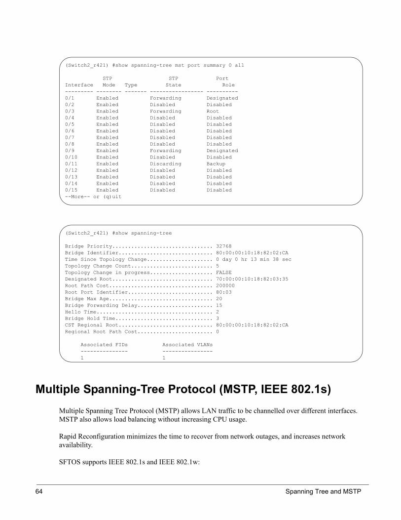
Multiple Spanning-Tree Protocol (MSTP, IEEE 802.1s)Multiple Spanning Tree Protocol (MSTP) allows LAN traffic to be channelled over different interfaces. MSTP also allows load balancing without increasing CPU usage.
Rapid Reconfiguration minimizes the time to recover from network outages, and increases network availability.
SFTOS supports IEEE 802.1s and IEEE 802.1w:
(Switch2_r421) #show spanning-tree mst port summary 0 all
STP STP PortInterface Mode Type State Role--------- -------- ------- ----------------- ----------0/1 Enabled Forwarding Designated0/2 Enabled Disabled Disabled0/3 Enabled Forwarding Root0/4 Enabled Disabled Disabled0/5 Enabled Disabled Disabled0/6 Enabled Disabled Disabled0/7 Enabled Disabled Disabled0/8 Enabled Disabled Disabled0/9 Enabled Forwarding Designated0/10 Enabled Disabled Disabled0/11 Enabled Discarding Backup0/12 Enabled Disabled Disabled0/13 Enabled Disabled Disabled0/14 Enabled Disabled Disabled0/15 Enabled Disabled Disabled--More-- or (q)uit
(Switch2_r421) #show spanning-tree
Bridge Priority................................ 32768Bridge Identifier.............................. 80:00:00:10:18:82:02:CATime Since Topology Change..................... 0 day 0 hr 13 min 38 secTopology Change Count.......................... 5Topology Change in progress.................... FALSEDesignated Root................................ 70:00:00:10:18:82:03:35Root Path Cost................................. 200000Root Port Identifier........................... 80:03Bridge Max Age................................. 20Bridge Forwarding Delay........................ 15Hello Time..................................... 2Bridge Hold Time............................... 3CST Regional Root.............................. 80:00:00:10:18:82:02:CARegional Root Path Cost........................ 0
Associated FIDs Associated VLANs --------------- ---------------- 1 1
64 Spanning Tree and MSTP

• The overall Root bridge for 802.1s is calculated in the same way as for 802.1D or 802.1w.• IEEE 802.1s bridges can interoperate with IEEE 802.1D and IEEE 802.1w bridges
MSTP Implementation
MSTP is part of the SFTOS switching package. Either IEEE 802.1D or IEEE 802.1s operates at any given time. The following is the SFTOS implementation of MSTP:
• One Common Instance (CIST) and 4 additional Multiple Instances (MSTIs)• VLANs are associated with one and only one instance of Spanning Tree• Multiple VLANs can be associated with an Instance of Spanning Tree• Each port supports multiple STP states, one state per instance. (Hence a port could be Forwarding in
one instance while Blocking in another instance.)
MST Regions
Multiple Spanning Tree region is a collection of MST bridges that share the same VLAN to STP instance mappings. They are administratively configured on each MST Bridge in the network.
MST regions are identified by:
• 32-byte alphanumeric configuration name• Two-byte configuration revision number• The mapping of VLAN IDs to STP instance numbers
MST Interactions
Bridge Protocol Data Units (BPDU) considerations:
• MSTP instances can only exist within in a region• MSTP instances never interact outside a region• MSTP BPDUs appear as normal BPDUs for the CIST while including information for the MSTIs (one
record for each MSTP Instance)• The CIST is mapped to Instance 0• Both ends of a link may send BPDUs at the same time, as they may be the designated ports for
different instances
MSTP Standards• Conforms to IEEE 802.1s• Compatible with IEEE 802.1w and IEEE 802.1D• SNMP management via a private MIB, as no standard MIB exists
SFTOS Configuration Guide, Version 2.1.4 65

MST CLI Management
Privileged and User Exec Mode display commands:• Display STP settings and parameters for the switch
— show spanning-tree summary
• Display settings and parameters for all MST instances— show spanning-tree mst summary
• Display settings and parameters for one MST instance— show spanning-tree mst detailed <mstid>
• Display settings and parameters for the CIST— show spanning-tree [brief]
• Display the association between an MST instance and a VLAN— show spanning-tree vlan <vlanid>
• Display settings and parameters for a port within an MST instance— show spanning-tree mst port summary <mstid> {<unit/slot/port> | all}— show spanning-tree mst port detailed <mstid> <unit/slot/port>
• Display settings and parameters for a port within the CIST— show spanning-tree interface <unit/slot/port>
Global Config Mode CLI commands:• [Disable] enable STP operational state for the switch
— [no] spanning-tree
• [Disable] enable STP administrative state for all ports— [no] spanning-tree port mode all
• [Reset] set the STP protocol version for the switch— spanning-tree forceversion <802.1d | 802.1w | 802.1s>
• [Reset] set a configuration name to identify the switch— [no] spanning-tree configuration name <name>
• [Reset] set the configuration revision level for the switch— [no] spanning-tree configuration revision <0-65535>
• [Reset] set max-age for the CIST— [no] spanning-tree max-age <6-40>
• [Reset] set forward-time for the CIST— [no] spanning-tree forward-time <4-30>
• [Reset] set hellp-time for the CIST— [no] spanning-tree hello-time <1-10>
• [Remove] add an MST instance— [no] spanning-tree mst <mstid>
• [Reset] set the bridge priority for an MST instance— [no] spanning-tree mst priority <mstid> <0-61440>
66 Spanning Tree and MSTP

• [Remove] add a VLAN to an MST instance— [no] spanning-tree mst vlan <mstid> <vlanid>
Interface Config Mode CLI commands:[Disable] enable administrative state for the port
— [no] spanning-tree port mode
• [Reset] set the path cost for this port for the MST instance, or for the CST if the mstid is 0. Auto sets the cost based on the link speed.— [no] spanning-tree mst <mstid> cost {<1-200000000> | auto}
• [Reset] set the port priority for this port for the MST instance, or for the CST, in increments of 16— [no] spanning-tree mst <mstid> port-priority <0-240>
• [Reset] set a port as an edge port within the CST— [no] spanning-tree edgeport
MSTP Configuration Example
Example topology:
• Switch B: 0/9 and 0/10 is VLAN 50. MST ID 50• Switch B: 0/11 and 0/12 is VLAN 60 MST ID 60• Switch A: 0/9 and 0/10 is VLAN 50 MST ID 50• Switch A: 0/11 and 0/12 is VLAN 50 MST ID 60
Steps1. Configure both switches B (root bridge)
2. Configure Switch A MST instance, assign the instance to the VLAN
3. Check STP state
4. Lower the priority of MST 50 which you want to discard (128 > 240)
5. Check STP state
HostHost
S50 A S50 B1/0/9 1/0/10
1/0/111/0/12
1/0/91/0/10
1/0/121/0/11
SFTOS Configuration Guide, Version 2.1.4 67

Verify
Configuration of Switch A: (non root bridge)
1. Switch A 50/60 Vlan0.10 F/D(forwarding/discarding)0.11 F/D(forwarding/discarding)
2. After lower the priority of MST 50, MST50 will change his STP state Switch A 50/60 Vlan
0.10 F/D(forwarding/discarding)0.11 D/F(discarding/forwarding)
set prompt "Switch A"remotecon timeout 0config lineconfig serial timeout 0 exitexit
config spanning-tree spanning-tree port mode allexit
vlan database vlan 50 vlan 60exitw
config spanning-tree mst instance 50 spanning-tree mst vlan 50 50 spanning-tree mst instance 60 spanning-tree mst vlan 60 60exit
show spanning-tree mst port summary 50 allshow spanning-tree mst port summary 60 all config interface 1/0/10
spanning-tree mst 50 port-priority 240 exitexit
show spanning-tree mst port summary 50 allshow spanning-tree mst port summary 60 all
* disable spanning-tree :config
no spanning-tree
68 Spanning Tree and MSTP

Command Examples
After lowering the priority of MST 50 :
Figure 22
(F10 Routing) #show spanning-tree mst port summary 50 all
STP STP PortInterface Mode Type State Role--------- -------- ------- ----------------- ----------0/1 Enabled Disabled Disabled0/2 Enabled Disabled Disabled0/3 Enabled Disabled Disabled0/4 Enabled Disabled Disabled0/5 Enabled Disabled Disabled0/6 Enabled Disabled Disabled0/7 Enabled Disabled Disabled0/8 Enabled Disabled Disabled0/9 Enabled Disabled Disabled0/10 Enabled Forwarding Designated0/11 Enabled Discarding Backup0/12 Enabled Disabled Disabled0/13 Enabled Disabled Disabled0/14 Enabled Disabled Disabled0/15 Enabled Disabled Disabled--More-- or (q)uit
(F10 Routing) #show spanning-tree mst port summary 50 all
STP STP PortInterface Mode Type State Role--------- -------- ------- ----------------- ----------0/1 Enabled Disabled Disabled0/2 Enabled Disabled Disabled0/3 Enabled Disabled Disabled0/4 Enabled Disabled Disabled0/5 Enabled Disabled Disabled0/6 Enabled Disabled Disabled0/7 Enabled Disabled Disabled0/8 Enabled Disabled Disabled0/9 Enabled Disabled Disabled0/10 Enabled Discarding Backup0/11 Enabled Forwarding Designated0/12 Enabled Disabled Disabled0/13 Enabled Disabled Disabled0/14 Enabled Disabled Disabled0/15 Enabled Disabled Disabled--More-- or (q)uit
SFTOS Configuration Guide, Version 2.1.4 69

70 Spanning Tree and MSTP

Link Aggregation—IEEE 802.3Link Aggregation Groups (LAG), or Trunking, allows IEEE 802.3 MAC interfaces to be grouped logically to appear as one physical link. LAG provides automatic redundancy between two devices. Each link of a LAG must run at the same speed and must be in full-duplex mode.
LAGs also provide the following:
• Behave like any other Ethernet link to VLAN.• Can be a member of a VLAN.• Is treated as a physical port with the same configuration parameters, spanning tree port priority, path
cost, etc.• A router port may be a member of a LAG, but routing will be disabled while it is a member.
LAG Implementation
Interface restrictions:
• LAG speed may not be changed• Routing is not supported on links in a LAG• An interface can belong to only one LAG• 32 LAGs, maximum of eight members each
SFTOS supports IEEE 802.3 Clause 43 with minor exceptions:
• No optional features supported, e.g. Marker Generator/Receiver• Mux machine implemented as coupled not independent control• Some MIB variables not supported.
Chapter 7 Link Aggregation
SFTOS Configuration Guide, Version 2.1.4 71

Static LAGs
Manual Aggregation
If the partner does not respond with LACPDUs, the system will wait three seconds and aggregate manually.
The static LAG configuration should only be enabled if both parties are 802.3ad-compliant and have the protocol enabled.
LAGs should be configured and STP enabled on both devices before connecting cables.
Manual aggregation uses the following default values:
• If an LACPDU is received with different values the link will drop out• When all member links have dropped out, the group will re-aggregate with the new information
Manual aggregation is disabled by default, and when enabled, applies to all LAG interfaces.
Link Aggregation—MIB Support
IEEE 802.3 Annex 30c MIB objects not supported:
• dot3adAggPortDebugTable• dot3adAggPortStatsMarkerResponsePDUsRx• dot3adAggPortStatsMarkerPDUsTx• dot3adAggPortActorAdminSystemPriority• dot3adAggPortActorOperSystemPriority• dot3adAggPortPartnerAdminSystemPriority• dot3adAggPortPartnerOperSystemPriority• dot3adTablesLastChanged
Link Aggregation CLI Management
Global Config mode CLI commands to create a LAG:
• Configure the LAG— port-channel {<logical unit/slot/port> | all | brief}
• (Use show port-channel all to display the logical unit/slot/port)— port-channel name {<logical unit/slot/port> | all} <name>— [no] port-channel linktrap {<logical unit/slot/port} | all}— spanning-tree stpmode {<logical unit/slot/port} | all} {off | 802.1d | fast}
• [Disable] enable the LAG— [no] port-channel adminmode {<logical unit/slot/port> | all}
72 Link Aggregation

• Delete all ports from a LAG:— deleteport <logical unit/slot/port> all
• Delete a LAG:— no port-channel {<logical unit/slot/port> | all}
LAG Configuration CLI Management
Interface Config mode CLI commands to configure a LAG:
• Add ports:— addport <logical unit/slot/port>
• Delete ports:— deleteport <logical unit/slot/port>
• Delete one or all LAGs:— delete interface {<logical unit/slot/port> | all}
Privileged Exec mode CLI command to display LAG information:
• Returns mode information • Lists members -- slot.port notation, link speed
— show port-channel {<logical unit/slot/port> | all | brief}
Static LAG CLI Management
Global Config Mode commands to disable/enable static capability for the switch:
• port-channel staticcapability— All LAGs with configured members but no active members will now aggregate statically on link
up interfaces— No effect on dynamic LAGs
• no port-channel staticcapability — Active members of static LAGs will drop. A LAG with no active members will go down
Privileged and User Exec Mode display command:
• show port-channel brief
— Displays whether static capability is enabled
SFTOS Configuration Guide, Version 2.1.4 73
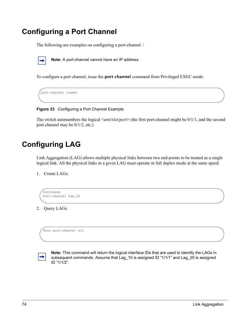
Configuring a Port ChannelThe following are examples on configuring a port-channel. \
To configure a port channel, issue the port channel command from Privileged EXEC mode:
Figure 23 Configuring a Port Channel Example
The switch autonumbers the logical <unit/slot/port> (the first port-channel might be 0/1/1, and the second port-channel may be 0/1/2, etc.)
Configuring LAGLink Aggregation (LAG) allows multiple physical links between two end-points to be treated as a single logical link. All the physical links in a given LAG must operate in full duplex mode at the same speed.
1. Create LAGs:
2. Query LAGs
Note: A port-channel cannot have an IP address.
Note: This command will return the logical interface IDs that are used to identify the LAGs in subsequent commands. Assume that Lag_10 is assigned ID “1/1/1” and Lag_20 is assigned ID “1/1/2”.
port-channel <name>
ConfigurePort-channel Lag_10
Show port-channel all
74 Link Aggregation

3. Add Ports to the appropriate LAGs
4. Enable both LAGs
5. Creation of static LAGs
Before Configuring LAG
Note: Link Trap Notification will be enabled by default. By default Dynamic LAGs will be created.
ConfigureInterface 1/0/2Addport 1/1/1ExitInterface 1/0/3Addport 1/1/1Exit
Inteface 1/0/8Addport “1/1/2”ExitInterface 1/0/9Addport “1/1/2”
ConfigurePort-channel adminmode all
ConfigurePort-channel staticcapabilityexit
(GSM7312) #show port-channel all
Log. Port- LinkSlot/ Channel Admin Trap STP Mbr Port PortPort Name Link Mode Mode Mode Type Ports Speed Active----- --------------- ---- ----- ---- ------ ------- ------ --------- ------
SFTOS Configuration Guide, Version 2.1.4 75

LAG Configuration Example
Displaying Port-channels
config port-channel lag-10 port-channel lag_20exit
show port-channel all
config interface 1/0/2 addport 1/1/1 exit interface 1/0/3 addport 1/1/1 exitexit
config interface 1/0/8 addport 1/1/2 exit interface 1/0/9 addport 1/1/2 exitexit
config port-channel adminmode all
exit
(GSM7312) #show port-channel all
Log. Port- LinkSlot/ Channel Admin Trap STP Mbr Port PortPort Name Link Mode Mode Mode Type Ports Speed Active----- --------------- ---- ----- ---- ------ ------- ------ --------- ------1/1/1 lag-10 Down En. En. En. Dynamic 0/2 Auto False
0/3 Auto False1/1/2 lag_20 Down En. En. En. Dynamic 0/8 Auto False
0/9 Auto False
76 Link Aggregation

Adding a Port-channel to a VLAN
To add a port-channel to a VLAN, use the vlan participation command:
Figure 24 Adding a Port-channel to a VLAN
MAC AddressesTo view MAC addresses, issue the show mac-addr-table command:
Figure 25 Viewing Port-channel Configuration
(S50) (Config)#interface 0/2/1 (S50) (Interface 0/2/1)#vlan participation include 11
(Force10 S50) #show mac-addr-table
Mac Address Interface IfIndex Status ----------------------- --------- ------- ------------00:01:00:01:00:00:00:01 2/0/37 87 Learned 00:01:00:01:00:00:00:37 1/0/1 1 Learned 00:01:00:03:00:00:00:03 1/0/2 2 Learned 00:01:00:03:00:00:00:39 2/0/38 88 Learned 00:01:00:04:00:00:00:45 2/0/45 95 Learned 00:01:00:04:00:00:00:46 1/0/45 45 Learned 00:01:00:06:00:00:00:47 2/0/46 96 Learned 00:01:00:06:00:00:00:48 1/0/46 46 Learned 00:01:00:D0:95:B7:CD:2E 0/3/1 401 Management
SFTOS Configuration Guide, Version 2.1.4 77

78 Link Aggregation

SFTOS supports two types of filtering: extended MAC access lists, and IP access lists. For both types, the general process for using them is the same:
• Create the access list• Apply the access list either globally to all ports, or to an individual interface.
ACL Commands
mac access-list extended
This command creates a MAC Access Control List (ACL) identified by <name>, consisting of classification fields defined for the Layer 2 header of an Ethernet frame.
• mac access-list extended <name>
(s50) (Config)#mac access-list extended ml-1
mac access-list extended rename
This command changes the name of a MAC Access Control List (ACL). This command fails if a MAC ACL by the name <newname> already exists.
• mac access-list extended rename <name> <newname>
{deny|permit}
This command creates a new rule for the current MAC access list. Each rule is appended to the list of configured rules for the list. Note that an implicit 'deny all' MAC rule always terminates the access list.
Chapter 8 ACLs
SFTOS Configuration Guide, Version 2.1.4 79
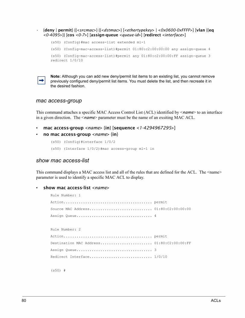
• {deny | permit} {{<srcmac>} {{<dstmac>} [<ethertypekey> | <0x0600-0xFFFF>] [vlan {{eq <0-4095>}} [cos <0-7>] [assign-queue <queue-id>] [redirect <interface>]
(s50) (Config)#mac access-list extended ml-1
(s50) (Config-mac-access-list)#permit 01:80:c2:00:00:00 any assign-queue 4
(s50) (Config-mac-access-list)#permit any 01:80:c2:00:00:FF assign-queue 3 redirect 1/0/10
mac access-group
This command attaches a specific MAC Access Control List (ACL) identified by <name> to an interface in a given direction. The <name> parameter must be the name of an exsiting MAC ACL.
• mac access-group <name> {in} [sequence <1-4294967295>]• no mac access-group <name> {in}
(s50) (Config)#interface 1/0/2
(s50) (Interface 1/0/2)#mac access-group ml-1 in
show mac access-list
This command displays a MAC access list and all of the rules that are defined for the ACL. The <name> parameter is used to identify a specific MAC ACL to display.
• show mac access-list <name>
Rule Number: 1
Action......................................... permit
Source MAC Address............................. 01:80:C2:00:00:00
Assign Queue................................... 4
Rule Number: 2
Action......................................... permit
Destination MAC Address........................ 01:80:C2:00:00:FF
Assign Queue................................... 3
Redirect Interface............................. 1/0/10
(s50) #
Note: Although you can add new deny/permit list items to an existing list, you cannot remove previously configured deny/permit list items. You must delete the list, and then recreate it in the desired fashion.
80 ACLs

show mac access-lists
This command displays a summary of all defined MAC access lists in the system.
• show mac access-lists
(s50) #show mac access-lists
Current number of all ACLs: 3 Maximum number of all ACLs: 100
MAC ACL Name Rules Interface(s) Direction
------------------------------- ----- ------------------------- ---------
ml-1 2 1/0/2 inbound
access-list
This command creates an Access Control List (ACL) that is identified by the parameter accesslistnumber.
• access-list {( 1-99 {deny | permit} srcip srcmask) | ( {100-199 {deny | permit} {evry | {{icmp | igmp | ip | tcp | udp | number} srcip srcmask [{eq {portkey | portvalue} | range startport endport}] dstip dstmask [{eq {portkey | portvalue} | range startport endport}] [precedence precedence] [tos tos tosmask] [dscp dscp]}})}
Access lists are of two types, normal access lists and extended access lists.
Normal
Uses a list number in the range of 1-99, matches source ip address, then takes the action of assigning the packet to a queue and / or redirecting the packet to a destination port.
• access-list <1-99> {deny | permit} {<srcip>< srcmask> | every } (assign-queue <queue-number>) (redirect <unit/slot/port>)
Extended
Uses a list number in the range of 100-199, matches protocol-type, then matches source and/or destination ip address/port, additionally matches ip-precedence, tos, dscp, then takes the action of assigning the packet to a queue and / or redirecting the packet to a destination port.. The command has the general form:
access-list <100-199> {deny | permit} <protocol><source/destination addr & port>{precedence | tos | dscp} (assign-queue) (redirect)
SFTOS Configuration Guide, Version 2.1.4 81

Example(s50) (Config)#access-list 100 permit ip any eq 80 any assign-queue 2 redirect 1/0/40
(s50) (Config)#
ip access-group
This command attach a specified access-control list to an interface.
• ip access-group accesslistnumber in | out
(s50) (Config)#interface 1/0/21
(s50) (Interface 1/0/21)#ip access-group 100 in 1
ip access-group
This command attach a specified access-control list to all interfaces from global Configuration mode.
• ip access-group accesslistnumber in | out
show ip access-lists
This command displays an Access Control List (ACL) and all of the rules that are defined for the ACL. The accesslistnumber is the number used to identify the ACL.
Note: You cannot edit a list once it is created, you must delete the list and create one as desired.
82 ACLs

• show ip access-lists accesslistnumber
(s50) #show ip access-lists
Current number of ACLs: 2 Maximum number of ACLs: 100
ACL ID Rules Interface(s) Direction
------ ----- ------------------------- ---------
1 1
100 1 1/0/21 inbound
(s50) #show ip access-lists 100
ACL ID: 100
Interface: 1/0/21
Rule Number: 1
Action......................................... permit
Match All...................................... FALSE
Protocol....................................... 255(ip)
Source L4 Port Keyword......................... 80(www/http)
Assign Queue................................... 2
Redirect Interface............................. 1/0/40
(s50) #
SFTOS Configuration Guide, Version 2.1.4 83

84 ACLs

The user configures Differentiated Services (Diffserv) in several stages by specifying:
• Class— Creating and deleting classes— Defining match criteria for a class. Note: The only way to remove an individual match criterion
from an existing class definition is to delete the class and re-create it.• Policy
— Creating and deleting policies— Associating classes with a policy— Defining policy statements for a policy/class combination
• Service— Adding and removing a policy to/from a directional (i.e., inbound, outbound) interface
Packets are filtered and processed based on defined criteria. The filtering criteria is defined by a class. The processing is defined by a policy’s attributes. Policy attributes may be defined on a per-class instance basis, and it is these attributes that are applied when a match occurs.
Packet processing begins by testing the match criteria for a packet. A policy is applied to a packet when a class match within that policy is found.
Note that the type of class - all, any, or ACL - has a bearing on the validity of match criteria specified when defining the class. A class type of ‘any’ processes its match rules in an ordered sequence; additional rules specified for such a class simply extend this list. A class type of ‘acl’ obtains its rule list by interpreting each ACL rule definition at the time the Diffserv class is created. Differences arise when specifying match criteria for a class type ‘all’, since only one value for each non-excluded match field is allowed within a class definition.
Chapter 9 Diff Serv
Note: If a field is already specified for a class, all subsequent attempts to specify the same field fail, including the cases where a field can be specified multiple ways through alternative formats. The exception to this is when the ‘exclude’ option is specified, in which case this restriction does not apply to the excluded fields.
SFTOS Configuration Guide, Version 2.1.4 85
The following class restrictions are imposed by the DiffServ design:
• Nested class support limited to:— any within any
— all within all
— No nested not conditions— No nested acl class types— Each class contains at most one referenced class
• Hierarchical service policies not supported in a class definition• Access list matched by reference only, and must be sole criterion in a class
— I.e., ACL rules copied as class match criteria at time of class creation, with class type any
— Implicit ACL deny all rule also copied— No nesting of class type acl
Regarding nested classes, referred to here as class references, a given class definition can contain at most one reference to another class, which can be combined with other match criteria. The referenced class is truly a reference and not a copy, since additions to a referenced class affect all classes that reference it. Changes to any class definition currently referenced by any other class must result in valid class definitions for all derived classes otherwise the change is rejected. A class reference may be removed from a class definition.
The user can display summary and detailed information for classes, policies and services. All configuration information is accessible via the CLI, Web, and SNMP user interfaces.
This command sets the DiffServ operational mode to active. While disabled, the DiffServ configuration is retained and can be changed, but it is not activated. When enabled, Diffserv services are activated.
Deploying DiffServFour steps are necessary to deploy DiffServ:
1. Create class-maps
These are used to differentiate between types of traffic based on a packet’s match to defined rules in a given class-map.
2. Create policy-maps
Policy-Maps reference class-maps and define the actions to be taken for traffic in a referenced class.
3. Apply the policy to interfaces
Apply the policy to the interfaces in an ingress or egress capacity.
4. Enable DiffServ Globally
We’ll take a brief look at each of these in turn.
86 Diff Serv

Creating Class-maps/DiffServ Classes
The class-map command is used to create DiffServ classes.
This command defines a new DiffServ class of type match-all, match-any or match-access-group. The<classname> parameter is a case sensitive alphanumeric string from 1 to 31 characters uniquely identifying the class.
When used without any match condition, this command enters the class-map mode. The <classname> is the name of an existing DiffServ class.
The class types
“match-all”—indicates all of the individual match conditions must be true for a packet to be considered a member of the class.
This command may be used without specifying a class type to enter the Class-Map Config mode for an existing DiffServ class.
class-map Command Syntax
To define the class-map, use these commands:
Note: Note: the class name 'default' is reserved and must not be used here.
Note: The class name 'default' is reserved and is not allowed here.
Note: The class match conditions are obtained from the referenced access list at the time of class creation. Thus, any subsequent changes to the referenced ACL definition do not affect the DiffServ class. To pick up the latest ACL definition, the DiffServ class must be deleted and re-created.
Note: The CLI mode is changed to Class-Map Config when this command is successfully executed.
SFTOS Configuration Guide, Version 2.1.4 87

The example below creates a class named “cl-map-1”. The map requires that all rules in the list must be matched. If any of the rules are not a match for the traffic, the traffic is not a member of that class. In this case, the traffic must carry a destination IP address in the 10.1.1.0 network and have a destination port of ‘7’:
Note that the example below, looks for packets with an ip-precedence of ‘1’, but also references another class map (cl-map-1):
To delete a class, use the command no class-map <classname>.
This command eliminates an existing DiffServ class. The <classname> is the name of an existing DiffServ class.
This command may be issued at any time; if the class is currently referenced by one or more policies or by any other class, this deletion attempt shall fail.
no class-map Command Syntax
To define the class-map, use these command:
Example:
Figure 26 no class-map Command Example
Note: The class name 'default' is reserved and is not allowed here.
Command Syntax Command Mode Purpose
no class-map <classname> Global CONFIG Eliminates an existing DiffServ class of specified type.
class-map match-all cl-map-1match dstip 10.1.1.0 255.255.255.0match dstl4port 7exit
class-map match-all cm-3match ip precedence 1match class-map cl-map-1exit
no class-map cl-map-1
88 Diff Serv

Creating a Policy-Map
The policy-map command set is used in DiffServ to define:
• Traffic Conditioning—Specify traffic conditioning actions (policing, marking, shaping) to apply to traffic classes
• Service Provisioning—Specify bandwidth and queue depth management requirements of service levels(EF, AF, etc.)
The policy commands are used to associate a traffic class, which was defined by the class command set, with one or more QoS policy attributes. This association is then assigned to an interface to form a service. The user specifies the policy name when the policy is created.
The DiffServ CLI does not necessarily require that users associate only one traffic class to one policy. In fact, multiple traffic classes can be associated with a single policy, each defining a particular treatment for packets that match the class definition. When a packet satisfies the conditions of more than one class, preference is based on the order in which the classes were added to the policy, with the foremost class taking highest precedence.
This set of commands consists of policy creation/deletion, class addition/removal, and individual policy attributes.
Note that the only way to remove an individual policy attribute from a class instance within a policy is to remove the class instance and re-add it to the policy. The values associated with an existing policy attribute can be changed without removing the class instance.
The policy-map command establishes a new DiffServ policy. The <policyname> parameter is a case-sensitive alphanumeric string from 1 to 31 characters uniquely identifying the policy. The type of policy is specific to either the inbound or outbound traffic direction as indicated by the {in | out} parameter.
Note: When removing the class-map, the reference to ‘match-any’, ‘match-all’, or ‘match-access-group’ is omitted.
Note: Class instances are always added to the end of an existing policy. While existing class instances may be removed, their previous location in the policy is not reused, so the number of class instance additions/removals is limited. In general, significant changes to a policy definition require that the entire policy be deleted and re-created with the desired configuration.
Note: The policy type dictates which of the individual policy attribute commands are valid within the policy definition.
SFTOS Configuration Guide, Version 2.1.4 89

To define the policy-map, use this command:
Example:
Figure 27 policy-map Command Example
In the above example, we’ve created a policy-map with the name of ‘pm-1’. This policy map is meant to affect inbound traffic. Traffic which is part of the class cl-map-1 (created in the previous example) is affected. Traffic which falls into this class will be assigned to queue ‘3’. Traffic which is a match for class cl-map-2 will have ip-precedence marked as ‘1’.
Applying Policies
Policy maps may be applied globally, to all interfaces, or on a per interface basis. This is accomplished with the service-policy <in|out> <policyname> command.
This command attaches a policy to an interface in a particular direction. The command can be used in the Interface Config mode to attach a policy to a specific interface. Alternatively, the command can be used in the Global Config mode to attach this policy to all system interfaces.
The direction value is either in or out.
The <policyname> parameter is the name of an existing DiffServ policy, whose type must match the interface direction. Note that this command causes a service to create a reference to the policy.
Note: The CLI mode is changed to Policy-Map Config when this command is successfully executed.
Command Syntax Command Mode Purpose
policy-map <policyname> <in | out> Global CONFIG Eliminates an existing DiffServ class of specified type.
Note: This command effectively enables DiffServ on an interface (in a particular direction).
policy-map pm-1 inclass cl-map-1assign-queue 3exit
class cl-map-2mark ip-precedence 1exit
90 Diff Serv

There is no separate interface administrative mode command for DiffServ.
Example (global):
Figure 28 service-policy Global Command Example
Example (per interface):
Figure 29 service-policy Interface Command Example
Enabling Differentiated Services
To use DiffServ, it must be enabled globally with the command diffserv. This command sets the DiffServ operational mode to active. While disabled, the DiffServ configuration is retained and can be changed, but it is not activated. When enabled, Diffserv services are activated.
Note: This command shall fail if any attributes within the policy definition exceed the capabilities of the interface. Once a policy is successfully attached to an interface, any attempt to change the policy definition such that it would result in a violation of said interface capabilities shall cause the policy change attempt to fail.
Command Syntax Command Mode Usage
service-policy <in | out> <policymapname>
GLOBAL ConfigInterface Config
Restrictions—Only a single policy may be attached to a particular interface in a particular direction at any one time.
Note: When applied globally, a service-policy command appears under each interface, as if the command were applied one interface at a time. The commands then can be removed from individual interfaces, or from all interfaces simultaneously using the ‘no’ form of the command.
(s50) #config(s50) (Config)#service-policy in pm-1(s50) (Config)#
(s50) #config(s50) (Config)#interface 1/0/4(s50) (Interface 1/0/4)#service-policy in pm-1(s50) (Interface 1/0/4)#
SFTOS Configuration Guide, Version 2.1.4 91
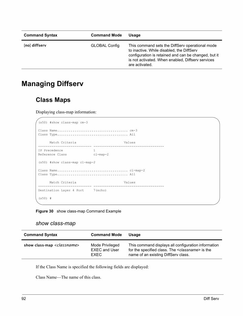
Managing Diffserv
Class Maps
Displaying class-map information:
Figure 30 show class-map Command Example
show class-map
If the Class Name is specified the following fields are displayed:
Class Name—The name of this class.
Command Syntax Command Mode Usage
[no] diffserv GLOBAL Config This command sets the DiffServ operational mode to inactive. While disabled, the DiffServ configuration is retained and can be changed, but it is not activated. When enabled, Diffserv services are activated.
Command Syntax Command Mode Usage
show class-map <classname> Mode Privileged EXEC and User EXEC
This command displays all configuration information for the specified class. The <classname> is the name of an existing DiffServ class.
(s50) #show class-map cm-3
Class Name..................................... cm-3Class Type..................................... All
Match Criteria Values---------------------------- -------------------------------------IP Precedence 1Reference Class cl-map-2
(s50) #show class-map cl-map-2
Class Name..................................... cl-map-2Class Type..................................... All
Match Criteria Values---------------------------- -------------------------------------Destination Layer 4 Port 7(echo)
(s50) #
92 Diff Serv

Class Type—The class type (all, any, or acl) indicating how the match criteria are evaluated for this class. A class type of all means every match criterion defined for the class is evaluated simultaneously they must all be true to indicate a class match. For a type of any each match criterion is evaluated sequentially and only one need be true to indicate a class match. Class type acl rules are evaluated in a hybrid manner, with those derived from each ACL Rule grouped and evaluated simultaneously, while each such grouping is evaluated sequentially.
Match Criteria—The Match Criteria fields are only be displayed if they have been configured. They are displayed in the order entered by the user. The fields are evaluated in accordance with the class type. The possible Match Criteria fields are: Class of Service, Destination IP Address, Destination Layer 4 Port, Destination MAC Address, Every, IP DSCP, IP Precedence, IP TOS, Protocol Keyword, Reference Class, Source IP Address, Source Layer 4 Port, Source MAC Address, CoS, Secondary CoS, and VLAN, Secondary VLAN, and Ethertype.
Values—This field displays the values of the Match Criteria.
Excluded—This field indicates whether or not this Match Criteria is excluded.
Figure 31 show class-map Command Example
If the Class Name is not specified, this command displays a list of all defined DiffServ classes. The following fields are displayed:
Class Name—The name of this class. (Note that the order in which classes are displayed is not necessarily the same order in which they were created.)
Class Type—The class type (all, any, or acl) indicating how the match criteria are evaluated for this class. A class type of all means every match criterion defined for the class is evaluated simultaneously they must all be true to indicate a class match.For a type of any each match criterion is evaluated sequentially and only one need be true to indicate a class match. Class type acl rules are evaluated in a hybrid manner, with those derived from each ACL Rule grouped and evaluated simultaneously, while each such grouping is evaluated sequentially.
ACL Number—The ACL number used to define the class match conditions at the time the class was created. This field is only meaningful if the class type is acl.
Note: The contents of the ACL may have changed since this class was created.
(s50) #show class-map
Class Class Name Type Reference Class Name------------------------------- ----- -------------------------------cl-map-1 Allcl-map-2 Allcm-3 All cl-map-2
(s50) #
SFTOS Configuration Guide, Version 2.1.4 93
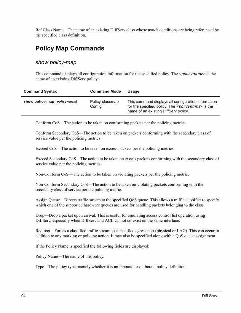
Ref Class Name—The name of an existing DiffServ class whose match conditions are being referenced by the specified class definition.
Policy Map Commands
show policy-map
This command displays all configuration information for the specified policy. The <policyname> is the name of an existing DiffServ policy.
Conform CoS—The action to be taken on conforming packets per the policing metrics.
Conform Secondary CoS—The action to be taken on packets conforming with the secondary class of service value per the policing metrics.
Exceed CoS—The action to be taken on excess packets per the policing metrics.
Exceed Secondary CoS—The action to be taken on excess packets conforming with the secondary class of service value per the policing metrics.
Non-Conform CoS—The action to be taken on violating packets per the policing metric.
Non-Conform Secondary CoS—The action to be taken on violating packets conforming with the secondary class of service per the policing metric.
Assign Queue—Directs traffic stream to the specified QoS queue. This allows a traffic classifier to specify which one of the supported hardware queues are used for handling packets belonging to the class.
Drop—Drop a packet upon arrival. This is useful for emulating access control list operation using DiffServ, especially when DiffServ and ACL cannot co-exist on the same interface.
Redirect—Forces a classified traffic stream to a specified egress port (physical or LAG). This can occur in addition to any marking or policing action. It may also be specified along with a QoS queue assignment.
If the Policy Name is specified the following fields are displayed:
Policy Name—The name of this policy.
Type—The policy type, namely whether it is an inbound or outbound policy definition.
Command Syntax Command Mode Usage
show policy-map [policyname] Policy-classmap Config
This command displays all configuration information for the specified policy. The <policyname> is the name of an existing DiffServ policy.
94 Diff Serv

The following information is repeated for each class associated with this policy (only those policy attributes actually configured are displayed):
Class Name—The name of this class.
Mark CoS—Denotes the class of service value that is set in the 802.1p header of outbound packets.
This is not displayed if the mark cos was not specified.
Mark IP DSCP—Denotes the mark/re-mark value used as the DSCP for traffic matching this class.
This is not displayed if mark ip description is not specified using the police-two-rate command, or if policing is in use for the class under this policy.
Mark IP Precedence—Denotes the mark/re-mark value used as the IP Precedence for traffic matching this class. This is not displayed if precedence is not specified using police-tworate command, or if either mark DSCP or policing is in use for the class under this policy.
Policing Style—This field denotes the style of policing, if any, used (simple, single rate, or two rate).
Committed Rate (Kbps)—This field displays the committed rate, used in simple policing, single-rate policing, and two-rate policing.
Committed Burst Size (KB)—This field displays the committed burst size, used in simple policing, single-rate policing, and two-rate policing.
Excess Burst Size (KB)—This field displays the excess burst size, used in single-rate policing.
Peak Rate (Kbps)—This field displays the peak rate, used in two-rate policing.
Peak Burst Size (KB)—This field displays the peak burst size, used in two-rate policing.
Conform Action—The current setting for the action taken on a packet considered to conform to the policing parameters. This is not displayed if policing is not in use for the class under this policy.
Conform DSCP Value—This field shows the DSCP mark value if the conform action is markdscp.
Conform IP Precedence Value—This field shows the IP Precedence mark value if the conform action is markprec.
Exceed Action—The current setting for the action taken on a packet considered to exceed to the policing parameters. This is not displayed if policing not in use for the class under this policy.
Exceed DSCP Value—This field shows the DSCP mark value if this action is markdscp.
Exceed IP Precedence Value—This field shows the IP Precedence mark value if this action is markprec.
Non-Conform Action—The current setting for the action taken on a packet considered to not conform to the policing parameters. This is not displayed if policing not in use for the class under this policy.
SFTOS Configuration Guide, Version 2.1.4 95

Non-Conform DSCP Value—This field displays the DSCP mark value if this action is markdscp.
Non-Conform IP Precedence Value—This field displays the IP Precedence mark value if this action is markprec.
Bandwidth—This field displays the minimum amount of bandwidth reserved in either percent or kilobits-per-second.
Expedite Burst Size (KBytes)—This field displays the maximum guaranteed amount of bandwidth reserved in either percent or kilobits-per-second format.
Shaping Average—This field is displayed if average shaping is in use. Indicates whether average or peak rate shaping is in use, along with the parameters used to form the traffic shaping criteria, such as CIR and PIR. This is not displayed if shaping is not configured for the class under this policy.
Shape Committed Rate (Kbps)—This field is displayed if average or peak rate shaping is in use. It displays the shaping committed rate in kilobits-per-second.
Random Drop Minimum Threshold—This field displays the RED minimum threshold.This is not displayed if the queue depth management scheme is not RED.
Random Drop Maximum Threshold—This field displays the RED maximum threshold.This is not displayed if the queue depth management scheme is not RED.
Random Drop Maximum Drop Probability—This field displays the RED maximum drop probability. This is not displayed if the queue depth management scheme is not RED.
Random Drop Sampling Rate—This field displays the RED sampling rate.This is not displayed if the queue depth management scheme is not RED.
Random Drop Decay Exponent—This field displays the RED decay exponent.This is not displayed if the queue depth management scheme is not RED.
The following is sample output from show policy-map:
Figure 32 show policy-map Command Example
If the Policy Name is not specified this command displays a list of all defined DiffServ policies. The following fields are displayed:
(s50) #show policy-map
Policy Name Policy Type Class Members------------------------------- ----------- -------------------------------pm-1 In cl-map-1 cl-map-2
(s50) #
96 Diff Serv
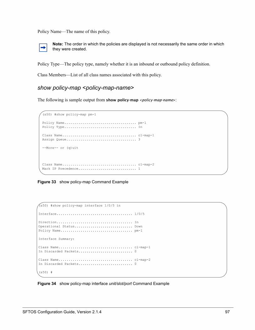
Policy Name—The name of this policy.
Policy Type—The policy type, namely whether it is an inbound or outbound policy definition.
Class Members—List of all class names associated with this policy.
show policy-map <policy-map-name>
The following is sample output from show policy-map <policy-map-name>:
Figure 33 show policy-map Command Example
Figure 34 show policy-map interface unit/slot/port Command Example
Note: The order in which the policies are displayed is not necessarily the same order in which they were created.
(s50) #show policy-map pm-1
Policy Name.................................... pm-1Policy Type.................................... In
Class Name..................................... cl-map-1Assign Queue................................... 3
--More-- or (q)uit
Class Name..................................... cl-map-2Mark IP Precedence............................. 1
(s50) #show policy-map interface 1/0/5 in
Interface...................................... 1/0/5
Direction...................................... InOperational Status............................. DownPolicy Name.................................... pm-1
Interface Summary:
Class Name..................................... cl-map-1In Discarded Packets........................... 0
Class Name..................................... cl-map-2In Discarded Packets........................... 0
(s50) #
SFTOS Configuration Guide, Version 2.1.4 97

show service-policy
The following information is repeated for each interface and direction (only those interfaces configured with an attached policy are shown):
Interface—Valid unit, slot and port number separated by forward slashes.
Dir—The traffic direction of this interface service, either in or out.
Operational Status—The current operational status of this DiffServ service interface.
Offered Packets—A count of the total number of packets offered to all class instances in this service before their defined DiffServ treatment is applied. These are overall per-interface perdirection counts.
Discarded Packets—A count of the total number of packets discarded for all class instances in this service for any reason due to DiffServ treatment. These are overall per-interface perdirection counts.
Sent Packets A count of the total number of packets forwarded for all class instances in this service after their defined DiffServ treatments were applied. In this case, forwarding means the traffic stream was passed to the next functional element in the data path, such as the switching or routing function or an outbound link transmission element. These are overall per-interface per-direction counts.
Policy Name The name of the policy attached to the interface.
Command Syntax Command Mode Usage
show service-policy <in|out> Privileged EXEC This command displays a summary of policy-oriented statistics information for all interfaces in the specified direction. The direction parameter indicates the interface direction of interest. This command enables or disables the route reflector client. A route reflector client relies on a route reflector to re-advertise its routes to the entire AS. The possible values for this field are enable and disable.
Note: None of the counters listed here are guaranteed to be supported on all platforms. Only supported counters are shown in the display output.
98 Diff Serv

Figure 35 show service-policy Command Example
Diffserv
show diffserv
DiffServ Admin mode—The current value of the DiffServ administrative mode.
Class Table Size—The current number of entries (rows) in the Class Table.
Class Table Max—The maximum allowed entries (rows) for the Class Table.
Class Rule Table Size—The current number of entries (rows) in the Class Rule Table.
Class Rule Table Max—The maximum allowed entries (rows) for the Class Rule Table.
Policy Table Size—The current number of entries (rows) in the Policy Table.
Policy Table Max—The maximum allowed entries (rows) for the Policy Table.
Policy Instance Table Size—The current number of entries (rows) in the Policy Instance Table.
Policy Instance Table Max—The maximum allowed entries (rows) for the Policy Instance Table.
Command Syntax Command Mode Usage
show diffserv Privileged EXEC This command displays the DiffServ General Status Group information, which includes the current administrative mode setting as well as the current and maximum number of rows in each of the main DiffServ private MIB tables. This command takes no options.
Service Policy
(s50) #show service-policy in
Oper Policy Intf Stat Name------- ---- -------------------------------1/0/1 Up pm-11/0/2 Down pm-11/0/3 Down pm-1<ouput deleted>(s50) #
SFTOS Configuration Guide, Version 2.1.4 99

Policy Attribute Table Size—The current number of entries (rows) in the Policy Attribute Table.
Policy Attribute Table Max—The maximum allowed entries (rows) for the Policy Attribute Table.
Service Table Size—The current number of entries (rows) in the Service Table.
Service Table Max—The maximum allowed entries (rows) for the Service Table.
The following are sample output from the show diffserv commands:
(s50) #show diffserv
DiffServ Admin mode............................ EnableClass Table Size Current/Max................... 3 / 25Class Rule Table Size Current/Max.............. 4 / 150Policy Table Size Current/Max.................. 1 / 64Policy Instance Table Size Current/Max......... 2 / 576Policy Attribute Table Size Current/Max........ 2 / 1728Service Table Size Current/Max................. 48 / 400
(s50) #
(s50) #show diffserv service brief
DiffServ Admin mode............................ Enable Interface Direction OperStatus Policy Name----------- ----------- ---------- -------------------------------1/0/1 In Up pm-11/0/2 In Down pm-11/0/3 In Down pm-1<output deleted>(s50) #
100 Diff Serv

IEEE 802.1Q VLAN support allows a network to be logically segmented without regard to the physical location of devices on the network—one physical network becomes multiple logical networks. These logical networks may, or may not, correspond to subnets.
Network segmentation provides:
• Better administration• Better security• Better management of multicast traffic• While maintaining Layer 2 forwarding speed
The VLAN tag in frames optionally carries priority information, and traffic between VLANs must be routed.
Important Points to Remember• Default VLAN is VLAN 1.• If a port is untagged, it can be member of multiple VLANs.• If a port is a member of multiple VLANs, it can be tagged in one VLAN and untagged in another.• If a port is a member of any VLAN, the port is implicitly included as part of the default VLAN 1
unless you explicitly exclude it using the command, vlan participation exclude 1.• If a port is untagged in VLAN 2, the port VLAN ID (PVID) number must be explictly configured
using the command vlan pvid 2 to be assigned to port 2. Therefore, any untagged packet coming into the port is treated as if it’s a member of VLAN 2. You must explicitly assign the PVID for the port; otherwise the default PVID for the port remains as 1.
• A packet with tag 2 coming into a port that is not a member of VLAN 2, is forwarded if the destination is known, or is flooded in VLAN 2 if its destination is unknown. Instead, to set this tag 2 packet so it is dropped when it comes into a port that is not a member of VLAN 2, you must enable vlan ingressfilter on that port.
• When an untagged packet comes into a tagged port, by default this packet is treated as a member of whatever PVID is set for that port. Instead, to set this untagged packet so it is dropped when it comes into a tagged port, you must add vlan acceptframe vlan only on that port.
• For tagged ports:
Chapter 10 IEEE 802.1Q VLANs
SFTOS Configuration Guide, Version 2.1.4 101

• For an untagged port that is a member of a VLAN:
VLANs ImplementationWith the SFTOS VLAN implementation, ports may belong to multiple VLANs, and VLAN membership may be based on port or protocol.
Switching is capable with VLAN-routing—the internal bridging and routing functions can act as logical ports of each other.
You may configure 1024 VLANs, of which can have any VLAN ID up to 3965. The top 129 VLANs are reserved.
When an individual port is added to a LAG, any VLAN membership is suspended, however the membership is automatically restored when the port is removed from the LAG.
Ingress Rules• Acceptable Frame Types parameter defaults to Admit All Frames• Port VLAN ID—default is 1, can be assigned by port or protocol
Step Command Syntax Command Mode Usage
1 vlan acceptframe vlan only INTERFACE So untagged packets are dropped when it comes into a tagged port.
2 vlan ingressfilter INTERFACE So tagged packets are dropped when it comes into a port that is not a member of a VLAN with the same numeric value as the tag of that packet.
3 vlan participation exclude number
INTERFACE To exclude a port from a VLAN.
Step Command Syntax Command Mode Usage
1 vlan ingressfilter INTERFACE So tagged packets are dropped when it comes into a port that is not a member of a VLAN with the same numeric value as the tag of that packet.
2 vlan pvid number INTERFACE To assign a VLAN to a port by number.
3 vlan participation exclude number
INTERFACE To exclude a port from a VLAN.
102 IEEE 802.1Q VLANs

• Ingress filtering defaults to disabled
Forwarding Rules
Forwarding rules are based on the following attributes:
• VLAN membership• Spanning tree state (forwarding)• Frame type (unicast or multicast)• Filters
Egress Rules• Spanning tree state (forwarding)• VLAN membership• Untagged frames only forwarded if embedded addresses are canonical
Exempt Frames• Spanning tree BPDUs• GVRP BPDUs• Frames used for control purposes, e.g. LAG PDUs, flow control
VLAN CLI ManagementPrivileged and User Exec Mode commands:
• Display summary information for all configured VLANs— show vlan brief
• Display detailed information for a specific VLAN— show vlan <1-4094>
• Display port-specific information for one or more VLANs— show vlan port {<slot/port | all>}
VLAN Database Mode Commands• [Delete] create a new VLAN and assign an ID
— [no] vlan <2-4094>
• Change a dynamically created VLAN to a static VLAN (permanently configure)— vlan makestatic <2-4094>
SFTOS Configuration Guide, Version 2.1.4 103

• [Reset] assign a name to a VLAN, VLAN 1 is always named Default, default for other VLANs is a blank string— [no] vlan name <2-4094> <name>
VLAN Configuration ExamplesTo create a VLAN, you must enter ENABLE mode, enter VLAN database mode, create the VLAN using the vlan command, then name it using vlan name:
1. Creating a VLAN.
2. Creating an IP VLAN:
3. Enable virtual router function:
Force10#vlan databasevlan 5vlan 10exit
configureinterface 0/2vlan participation exclude 1vlan participation include 5vlan pvid 5
interface 0/4vlan participation exclude 1vlan participation include 10vlan pvid 10exit
Force10#
vlan databaserouting 5routing 10exit
Force10#configureip routingexit
104 IEEE 802.1Q VLANs

4. Configuring a Virtual Interface. This example assumes you have assigned IP addresses to interfaces “x/1” and “x/2”:
5. Enabling a Routing Protocol (example: for RIP):
Viewing VLANs
To view VLANs, use the command show run and show brief. Note in the show brief output that VLAN 1 exists even though it was not configured:
Force10#configure
interface x/1 <---- (query the virtual interface created from step 2)ip address 192.168.1.1 255.255.255.0exit
interface x/2 ip address 182.168.1.2 255.255.255.0exit
router ripenableexit
interface x/1 (virtual interface from step 2)ip ripexit
interface x/2ip rip
(S50) #show run!Current Configuration:!
set prompt "S50"network parms 172.17.1.33 255.255.255.0 172.17.1.254vlan databasevlan 2vlan name 2 "v-2"vlan 3vlan name 3 "v-3"vlan 50exit(S50) #show vlan brief
VLAN ID VLAN Name VLAN Type------- -------------------------------- ---------1 Default Default2 v-2 Static3 v-3 Static50 Static
SFTOS Configuration Guide, Version 2.1.4 105

VLAN 1 is the default VLAN, and all interfaces are members of VLAN 1 by default.
Ingress Filtering
When ingress filtering is disabled, frames received with VLAN IDs that do not match the VLAN membership of the receiving interface are admitted and forwarded to ports that are members of that VLAN. To enable ingress filtering, use the command vlan ingressfilter:
Figure 36 vlan ingressfilter Command Example
Setting the VLAN ID
To set the VLAN ID for an interface, use the command vlan pvid. When the PVID is not explictly configured, the default setting is 1:
Figure 37 Configuring a VLAN PVID
Configuring VLAN Participation
The command vlan participation include includes the VLAN on the interface:
Figure 38 Configuring VLAN Participation
The following are the three options for participation:
• include—the interface is always a member of this VLAN. (Equivalent to registration fixed.)
Note: By default, SFTOS drops any frames which do not match the configured VLANs of an interface.
Note: An untagged port may include multiple VLANs.
(S50) (Interface 1/0/4)#vlan ingressfilter
(S50) (Interface 1/0/4)#vlan pvid 2
(S50) (Interface 1/0/4)#vlan participation include 2
106 IEEE 802.1Q VLANs
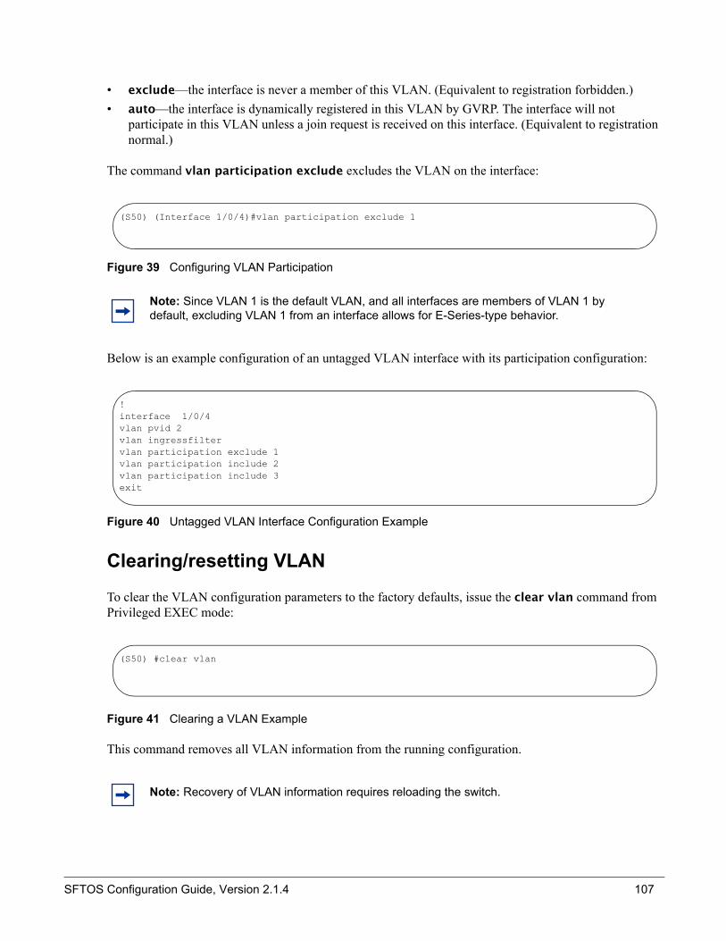
• exclude—the interface is never a member of this VLAN. (Equivalent to registration forbidden.)• auto—the interface is dynamically registered in this VLAN by GVRP. The interface will not
participate in this VLAN unless a join request is received on this interface. (Equivalent to registration normal.)
The command vlan participation exclude excludes the VLAN on the interface:
Figure 39 Configuring VLAN Participation
Below is an example configuration of an untagged VLAN interface with its participation configuration:
Figure 40 Untagged VLAN Interface Configuration Example
Clearing/resetting VLAN
To clear the VLAN configuration parameters to the factory defaults, issue the clear vlan command from Privileged EXEC mode:
Figure 41 Clearing a VLAN Example
This command removes all VLAN information from the running configuration.
Note: Since VLAN 1 is the default VLAN, and all interfaces are members of VLAN 1 by default, excluding VLAN 1 from an interface allows for E-Series-type behavior.
Note: Recovery of VLAN information requires reloading the switch.
(S50) (Interface 1/0/4)#vlan participation exclude 1
!interface 1/0/4vlan pvid 2vlan ingressfiltervlan participation exclude 1vlan participation include 2vlan participation include 3exit
(S50) #clear vlan
SFTOS Configuration Guide, Version 2.1.4 107

Tagged Ports
To configure a tagged port for VLANs 10 and 11 only, on port 1/0/1:
Figure 42 Configuring a Tagged Port for VLANs
To configure an untagged port for VLAN 10 on port 1/0/1:
Figure 43 Configuring a Tagged Port for VLANs
(S50) (Config)#interface 1/0/1! Only accept tagged frames(S50) (Interface 1/0/1)#vlan acceptframe all vlanonly! Only forward traffic in configured VLANs(S50) (Interface 1/0/1)#vlan ingressfilter ! Exclude VLAN 1(S50) (Interface 1/0/1)#vlan participation exclude 1! Include VLAN 10(S50) (Interface 1/0/1)#vlan participation include 10! Transmit tagged frames for VLAN 10(S50) (Interface 1/0/1)#vlan port tagging 10 ! Include VLAN 11(S50) (Interface 1/0/1)#vlan participation include 11! Transmit tagged frames for VLAN 11(S50) (Interface 1/0/1)#vlan port tagging 11
(S50) (Config)#interface 1/0/1! Only forward traffic in configured VLANs(S50) (Interface 1/0/1)#vlan ingressfilter! Set the VLAN ID to 10(S50) (Interface 1/0/1)#vlan pvid 10 ! Exclude VLAN 1(S50) (Interface 1/0/1)#vlan participation exclude 1! Include VLAN 10(S50) (Interface 1/0/1)#vlan participation include 10
108 IEEE 802.1Q VLANs

Showing VLAN Configuration
Use the show vlan command to view VLAN configuration:
Figure 44 show vlan Example
S50 and E-Series DifferencesThere are differences between the S50 and the E-Series hardware.
Table 2 Differences Between the S50 and E-Series
S50 E-SeriesUntagged ports can be a member of many VLANs.
Untagged ports can be a member of one VLAN.
A port can be tagged in one VLAN and untagged in another VLAN.
If a port is member of multiple VLANs, it has to be tagged.
A port is a member of VLAN 1 until explicitly excluded.
When a port is assigned a VLAN, the port is implicitly excluded from VLAN 1 (the default VLAN).
A port forwards traffic in VLAN 1 even when assigned a VLAN, until configured with the vlan pvid command.
When a port is assigned a VLAN, all traffic on the port is forwarded in that VLAN.
(s50) #show vlan 1
VLAN ID: 1VLAN Name: DefaultVLAN Type: Default
Interface Current Configured Tagging---------- -------- ----------- --------1/0/1 Include Include Untagged1/0/2 Include Include Untagged1/0/3 Include Include Untagged1/0/4 Include Include Untagged1/0/5 Include Include Untagged1/0/6 Include Include Untagged1/0/7 Include Include Untagged1/0/8 Include Include Untagged1/0/9 Include Include Untagged1/0/10 Include Include Untagged1/0/11 Include Include Untagged1/0/12 Include Include Untagged1/0/13 Include Include Untagged1/0/14 Include Include Untagged1/0/15 Include Include Untagged1/0/16 Include Include Untagged...
SFTOS Configuration Guide, Version 2.1.4 109

The following examples demonstrate how to configure a tagged and untagged port on the S50 to behave the same way as on the E-Series.
Traffic received on a port for a VLAN that is not configured on the port is forwarded if the destination is known, or flooded in that VLAN if the destination is unknown. The vlan ingressfilter command can be used to only forward traffic for VLANs that are configured on the port.
Traffic received on a port for a VLAN that is not configured on the port is dropped.
Untagged traffic is forwarded in the VLAN configured with the vlan pvid command. To only accept tagged frames on the port, use the vlan acceptframe vlan only command.
Untagged traffic received on a port that is configured as a tagged port is dropped.
S50 E-SeriesTo configure a tagged port for VLANs 10 and 11 on port 1/0/1:
(S50) (Config)#interface 1/0/1! Only accept tagged frames(S50) (Interface 1/0/1)#vlan acceptframe vlanonly ! Only forward traffic in configured VLANs(S50) (Interface 1/0/1)#vlan ingressfilter ! Exclude VLAN 1(S50) (Interface 1/0/1)#vlan participation exclude 1! Include VLAN 10(S50) (Interface 1/0/1)#vlan participation include 10! Transmit tagged frames for VLAN 10(S50) (Interface 1/0/1)#vlan tagging 10 ! Include VLAN 11(S50) (Interface 1/0/1)#vlan participation include 11! Transmit tagged frames for VLAN 11(S50) (Interface 1/0/1)#vlan tagging 11
To configure a tagged port for VLANs 10 and 11 on port g0/1:
Force10(conf)#interface g0/1Force10(conf-if-gi-0/1)#switchport Force10(conf-if-gi-0/1)#interface vlan 10Force10(conf-if-vl-10)#tagged g0/1Force10(conf-if-gi-0/1)#interface vlan 11Force10(conf-if-vl-11)#tagged g0/1
To configure an untagged port for VLAN 10 on port 1/0/1:
(S50) (Config)#interface 1/0/1! Only forward traffic in configured VLANs(S50) (Interface 1/0/1)#vlan ingressfilter! Set the VLAN ID to 10(S50) (Interface 1/0/1)#vlan pvid 10 ! Exclude VLAN 1(S50) (Interface 1/0/1)#vlan participation exclude 1! Include VLAN 10(S50) (Interface 1/0/1)#vlan participation include 10
To configure an untagged port for VLAN 10 on port g0/1:
Force10(conf)#interface g0/1Force10(conf-if-gi-0/1)#switchport Force10(conf-if-gi-0/1)#interface vlan 10Force10(conf-if-vl-10)#untagged g0/1
Table 2 Differences Between the S50 and E-Series
S50 E-Series
110 IEEE 802.1Q VLANs

To configure the S50 to have functionality of the E-series, the following tasks must be executed:
• For tagged ports:
1.VLAN acceptframe VLAN only
2.VLAN ingressfilter
3.VLAN participation exclude 1
• For untagged ports (for example, the port is member of VLAN 4):
1.VLAN ingressfilter
2.VLAN PVID 4
3.VLAN participation exclude 1
SFTOS Configuration Guide, Version 2.1.4 111

112 IEEE 802.1Q VLANs
Generic Attribute Registration Protocol (GARP) provides a generic attribute dissemination protocol used to support other protocols such as GVRP. GARP is used to register and deregister attribute values with other GARP participants within bridged LANs. When a GARP participant declares or withdraws a given attribute, the attribute value is recorded with the applicant state machine for the port from which the declaration or withdrawal was made.
• There exists a GARP participant per port per GARP application (e.g. GVRP)
GARP VLAN Registration Protocol (GVRP)• GVRP propagates VLAN membership throughout a network• GVRP allows end stations and SFTOS™ Switching devices to issue and revoke declarations relating
to VLAN membership• VLAN registration is made in the context of the port that receives the GARP PDU and is propagated to
the other active ports• GVRP is disabled by default -- user must enable GVRP for the switch and then for individual ports• Dynamic VLANs are aged out after the LeaveAllTimer expires three times without receipt of a join
message
SFTOS™ Switching complies with:
• IEEE 802.1D • IEEE 802.1Q
GARP Multicast Registration Protocol (GMRP)• GMRP propagates group membership throughout a network.• GMRP allows end stations and SFTOS™ Switching devices to issue and revoke declarations relating
to group membership.• (De)registration updates the Multicast Forwarding Database—multicast packets only forwarded
through ports with a GMRP registration.• GMRP is disabled by default—user must enable GMRP for the switch and then for individual ports.
Chapter 11 GARP Timers
SFTOS Configuration Guide, Version 2.1.4 113
GARP Implementation• GMRP is part of the SFTOS Switching package
— Interacts with the Spanning Tree Protocol , GARP and the Multicast Forwarding Database— Requires Independent VLAN Learning
• There is an instance of GMRP for each VLAN• MAC addresses are qualified by the two byte VLAN ID
• SFTOS GMRP complies with:— IEEE 802.1D Clause 10— GMRP Port configuration and Status Table from RFC 2674
• SFTOS limitations— Default filtering behavior is not supported— Static entries are not coordinated
GARP TimersThe following are GARP timers:
• JoinTimer— Controls the interval of GMRP PDU transmission— Default value: 20 centiseconds
• LeaveTimer— Controls the time period after the de-registration process is started for a registered attribute— Default value: 60 centiseconds
• Should be at least twice the JoinTimer• LeaveAllTimer
— Controls the frequency with which LeaveAll event GARP PDU is transmitted— Default value: 1000 centiseconds
• Should be considerably longer than LeaveTimer
GARP Commands1. Enable GARP VLAN Registration Protocol (GVRP) or GARP Multicast Registration Protocol
(GMRP) for the switch:
set {gvrp | gmrp} adminmode
114 GARP Timers
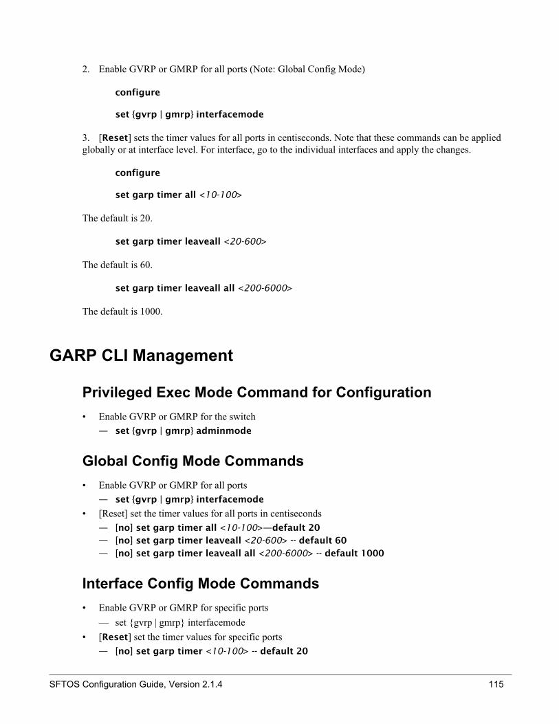
2. Enable GVRP or GMRP for all ports (Note: Global Config Mode)
configure
set {gvrp | gmrp} interfacemode
3. [Reset] sets the timer values for all ports in centiseconds. Note that these commands can be applied globally or at interface level. For interface, go to the individual interfaces and apply the changes.
configure
set garp timer all <10-100>
The default is 20.
set garp timer leaveall <20-600>
The default is 60.
set garp timer leaveall all <200-6000>
The default is 1000.
GARP CLI Management
Privileged Exec Mode Command for Configuration• Enable GVRP or GMRP for the switch
— set {gvrp | gmrp} adminmode
Global Config Mode Commands• Enable GVRP or GMRP for all ports
— set {gvrp | gmrp} interfacemode
• [Reset] set the timer values for all ports in centiseconds— [no] set garp timer all <10-100>—default 20— [no] set garp timer leaveall <20-600> -- default 60— [no] set garp timer leaveall all <200-6000> -- default 1000
Interface Config Mode Commands• Enable GVRP or GMRP for specific ports
— set {gvrp | gmrp} interfacemode• [Reset] set the timer values for specific ports
— [no] set garp timer <10-100> -- default 20
SFTOS Configuration Guide, Version 2.1.4 115

— [no] set garp timer leave <20-600> -- default 60— [no] set garp timer leaveall <200-6000> -- default 1000
GARP Properties
This is a list of Privileged and User Exec mode commands that displays GARP information for the switch:
• show garp info
— Admin mode for GVRP and GMRP
This is a list of Privileged and User Exec mode commands that displays GARP/GVRP information for the switch:
• show gmrp configuration {<unit/slot/port> | all}
• show gvrp configuration {<unit/slot/port> | all}
— Port admin mode for GVRP and GMRP— Timer values
116 GARP Timers

The following example shows how to enable GVRP for all ports in switch:
Figure 45 Enabling GVRP Example
Summary: GVRP is used to exchange the VLAN number, in this case is VLAN 10
Test Setup Configuration Example• Two switches link by port 0/2• Both switches enable GVRP. • Switch1 has 1/0/1 and 1/0/2 belong to VLAN 10.• Send GVRP join_in from Switch1 1/0/1, Switch2 2/0/2 becomes VLAN 10.• Send GVRP join_in from Switch2 0/10. • Check that VLAN 10's traffic goes through Switch1 1/0/1 to Switch2 2/0/10. Creating a VLAN.
Enabling and Verifying GVRP
1. Enable GVRP.
2. Create VLAN and add the daisy chain port (1/0/2) to all VLANs.
3. Verify the VLAN learned by the command show vlan brief.
4. Verify the GARP admin mode by the command show garp.
5. Verify the GARP interface by the command show gvrp configuration all.
• Switch2 learns VLAN 10.• Port 0/2 will become VLAN 10 and VLAN 10 traffic can go through.
Chapter 12 GVRP
set gvrp adminmode config set gvrp interfacemode all
exit
SFTOS Configuration Guide, Version 2.1.4 117
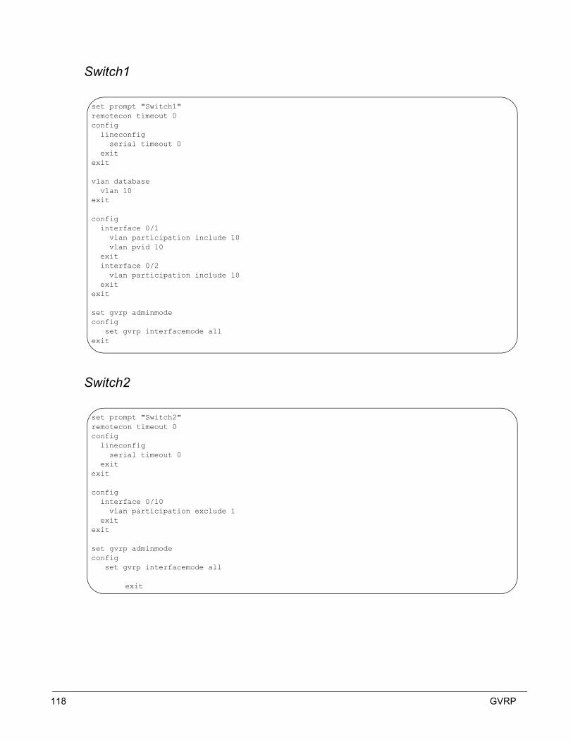
Switch1
Switch2
set prompt "Switch1"remotecon timeout 0config lineconfig serial timeout 0 exitexit
vlan database vlan 10exit
config interface 0/1 vlan participation include 10 vlan pvid 10 exit interface 0/2 vlan participation include 10 exitexit
set gvrp adminmode config set gvrp interfacemode allexit
set prompt "Switch2"remotecon timeout 0config lineconfig serial timeout 0 exitexit
config interface 0/10 vlan participation exclude 1 exitexit
set gvrp adminmode config set gvrp interfacemode all
exit
118 GVRP

show vlan brief
vlan participation exlude 1
(F10 Routing) #show vlan brief
VLAN ID VLAN Name VLAN Type------- -------------------------------- ---------1 Default Default
(F10 Routing) #set prompt "Switch2"
(Switch2) #remotecon timeout 0
(Switch2) #config
(Switch2) (Config)#lineconfig
(Switch2) (Line) #serial timeout 0
(Switch2) (Line) #exit
(Switch2) (Config)#exit
(Switch2) (Config)#interface 0/10
(Switch2) (Interface 0/10)#vlan participation exclude 1
(Switch2) (Interface 0/10)#exit
(Switch2) (Config)#exit
(Switch2) #set gvrp adminmode
Change will be applied in the next 10 seconds.
(Switch2) #config
(Switch2) (Config)#set gvrp interfacemode all
Change will be applied in the next 10 seconds.
(Switch2) (Config)#exit
SFTOS Configuration Guide, Version 2.1.4 119
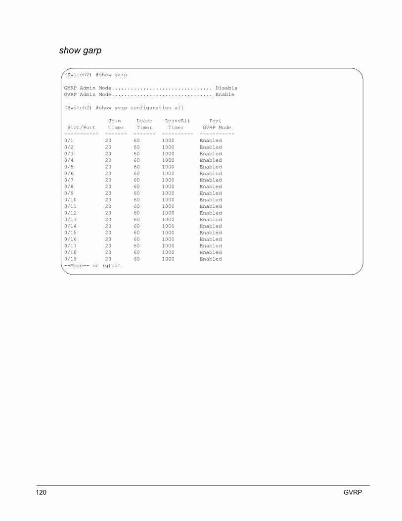
show garp
(Switch2) #show garp
GMRP Admin Mode................................ DisableGVRP Admin Mode................................ Enable
(Switch2) #show gvrp configuration all
Join Leave LeaveAll Port Slot/Port Timer Timer Timer GVRP Mode----------- ------- ------- ---------- -----------0/1 20 60 1000 Enabled0/2 20 60 1000 Enabled0/3 20 60 1000 Enabled0/4 20 60 1000 Enabled0/5 20 60 1000 Enabled0/6 20 60 1000 Enabled0/7 20 60 1000 Enabled0/8 20 60 1000 Enabled0/9 20 60 1000 Enabled0/10 20 60 1000 Enabled0/11 20 60 1000 Enabled0/12 20 60 1000 Enabled0/13 20 60 1000 Enabled0/14 20 60 1000 Enabled0/15 20 60 1000 Enabled0/16 20 60 1000 Enabled0/17 20 60 1000 Enabled0/18 20 60 1000 Enabled0/19 20 60 1000 Enabled--More-- or (q)uit
120 GVRP

show vlan 1
show vlan brief
• Switch1 port 0/1 sends in GVRP join_in packet.• Switch2 port 0/2 becomes the dynamic VLAN 10. • Port 0/10 won't get it, because it is not included in VLAN 1.
(Switch2) #show vlan 1
VLAN ID: 1VLAN Name: DefaultVLAN Type: Default
slot/port Current Configured Tagging---------- -------- ----------- -------- 0/1 Include Include Untagged 0/2 Include Include Untagged 0/3 Include Include Untagged 0/4 Include Include Untagged 0/5 Include Include Untagged 0/6 Include Include Untagged 0/7 Include Include Untagged 0/8 Include Include Untagged 0/9 Include Include Untagged 0/10 Exclude Exclude Untagged 0/11 Include Include Untagged 0/12 Include Include Untagged 0/13 Include Include Untagged 0/14 Include Include Untagged 0/15 Include Include Untagged 0/16 Include Include Untagged--More-- or (q)uit
(Switch2) #show vlan brief
VLAN ID VLAN Name VLAN Type------- -------------------------------- ---------1 Default Default10 Dynamic
SFTOS Configuration Guide, Version 2.1.4 121
show vlan 10
• Send GVRP v10 from Switch2 0/10
(Switch2) #show vlan 10
VLAN ID: 10VLAN Name:VLAN Type: Dynamic
slot/port Current Configured Tagging---------- -------- ----------- -------- 0/1 Exclude Autodetect Untagged 0/2 Include Autodetect Tagged 0/3 Exclude Autodetect Untagged 0/4 Exclude Autodetect Untagged 0/5 Exclude Autodetect Untagged 0/6 Exclude Autodetect Untagged 0/7 Exclude Autodetect Untagged 0/8 Exclude Autodetect Untagged 0/9 Exclude Autodetect Untagged 0/10 Exclude Autodetect Untagged 0/11 Exclude Autodetect Untagged 0/12 Exclude Autodetect Untagged 0/13 Exclude Autodetect Untagged 0/14 Exclude Autodetect Untagged 0/15 Exclude Autodetect Untagged 0/16 Exclude Autodetect Untagged--More-- or (q)uit
122 GVRP

show vlan 10
Verify VLAN 10 traffic, if Switch1 sends the VLAN 10 packet, then Switch2 0/10 will recieve it.
(Switch2) #show vlan 10
VLAN ID: 10VLAN Name:VLAN Type: Dynamic
slot/port Current Configured Tagging---------- -------- ----------- -------- 0/1 Exclude Autodetect Untagged 0/2 Include Autodetect Tagged 0/3 Exclude Autodetect Untagged 0/4 Exclude Autodetect Untagged 0/5 Exclude Autodetect Untagged 0/6 Exclude Autodetect Untagged 0/7 Exclude Autodetect Untagged 0/8 Exclude Autodetect Untagged 0/9 Exclude Autodetect Untagged 0/10 Include Autodetect Tagged 0/11 Exclude Autodetect Untagged 0/12 Exclude Autodetect Untagged 0/13 Exclude Autodetect Untagged 0/14 Exclude Autodetect Untagged 0/15 Exclude Autodetect Untagged 0/16 Exclude Autodetect Untagged--More-- or (q)uit
SFTOS Configuration Guide, Version 2.1.4 123

124 GVRP

VLAN-stack commands1. Enable VLAN-stack for a specific interface:
mode dvlan-tunnel
mode dot1q-tunnel
2. Configure the customer ID for an interface
dvlan-tunnel customer-id <0-4095>
3. Configure the ether-type for an interface
dvlan-tunnel ethertye {802.1Q | vman | custom} [0-65535]
4. Display DVLANs enabled vlan tagging.
show dvlan-tunnel or
show dot1q-tunnel
— Shows all interfaces that have DVLAN tagging enabled.
5. Display detailed information for a specific interface
show dvlan-tunnel interface {<unit/slot/port> | all}
show dot1q-tunnel interface {<unit/slot/port> | all}
Chapter 13 VLAN-Stack
SFTOS Configuration Guide, Version 2.1.4 125

126 VLAN-Stack

Typically a switch employing IGMP snooping forwards multicast packets out all ports in a VLAN until it receives an IGMP membership report.
Commands
1. Enable IGMP Snooping
set igmp <vlanid>
— When inputting the variable <vlan id>, command must be typed from VLAN database mode, and not from Interface Config.
2. Enable IGMP Snooping on all interfaces
set igmp interfacemode
3. Commands to configure timers:
set igmp groupmembershipinterval <vlanid> <2-3600>
— Default 125 seconds— When inputting the variable <vlan id>, command must be typed from VLAN database
mode, and not from Interface Config.
set igmp maxresponse <vlanid> <1-less than group membership interval>
— Default 10 seconds— When inputting the variable <vlan id>, command must be typed from VLAN database
mode, and not from Interface Config.
set igmp mcrtexpiretime <vlanid> <0-3600>
— Default 0 seconds (no expiration)— If the command is used from Global config, it sets the time for all routers.
Chapter 14 IGMP Snooping
SFTOS Configuration Guide, Version 2.1.4 127

128 IGMP Snooping
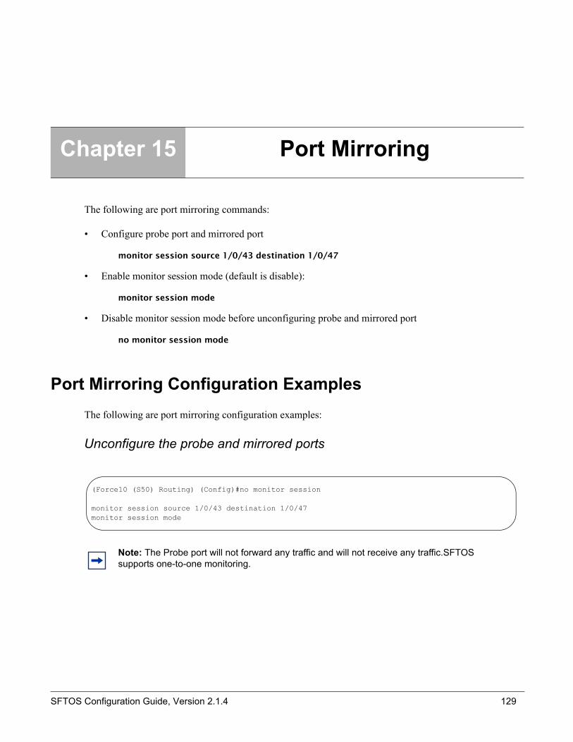
The following are port mirroring commands:
• Configure probe port and mirrored port
monitor session source 1/0/43 destination 1/0/47
• Enable monitor session mode (default is disable):
monitor session mode
• Disable monitor session mode before unconfiguring probe and mirrored port
no monitor session mode
Port Mirroring Configuration ExamplesThe following are port mirroring configuration examples:
Unconfigure the probe and mirrored ports
Chapter 15 Port Mirroring
Note: The Probe port will not forward any traffic and will not receive any traffic.SFTOS supports one-to-one monitoring.
(Force10 (S50) Routing) (Config)#no monitor session
monitor session source 1/0/43 destination 1/0/47monitor session mode
SFTOS Configuration Guide, Version 2.1.4 129

• Probe port is not network connected:
Verify monitor session status
Configuration example
• mirrored port 1/0/1; probe port 1/0/2
(Force10 (S50) Routing) #show vlan port 1/0/47
Port Acceptable Ingress DefaultInterface VLAN ID Frame Types Filtering GVRP Priority--------- ------- ------------ ----------- ------- --------
(Force10 (S50) Routing) #show monitor
Port Monitor Mode.............................. EnableProbe Port..................................... 1/0/47Mirrored Port.................................. 1/0/39
config monitor session source 1/0/1 destination 1/0/2 monitor session modeexit
config no monitor session mode no monitor sessionexit
Verify : show monitor
130 Port Mirroring

Index
Aaccess-list 81ACL Commands 79Adding a Port-channel to a VLAN 77Applying Policies 90audience 7
CChanging the Management VLAN from Default VLAN 140Checking Interface Counters Per Port 41Class 85class types 87class-map Command Syntax 87Clearing Running-configuration 19Clearing/resetting, VLAN 107CLI Overview 17Commands, IGMP Snooping 127Configuration Example, GVRP 117Configuring a Port Channel 74Configuring an Interface with an IP Address 25Configuring from the Network 27Configuring LAG 74Connecting a Cable to the Console Port 11Creating a Policy-Map 89Creating a User and a Password 19Creating a User and Password 18Creating the Management Port IP 39
DDeleting Configuration File to Access System 22deny permit, QoS 79Deploying DiffServ 86Differentiated Services (Diffserv) 85Discovery Messages 43Displaying Logs 28Displaying Statistics 29Displaying Supported Features 20Displaying System Uptime 20Document conventions 7dot3adTablesLastChanged Link Aggregation CLI Man-agement 72Downloading Files 13
EEgress Rules, VLAN 103Enabling and Verifying, GVRP 117Enabling Differentiated Services 91
Exempt Frames, VLAN 103
FForceversion Command 54Forwarding Rules, VLAN 103Forwarding, Aging, and Learning 53
GGARP 114GARP CLI Management 115GARP Multicast Registration Protocol (GMRP) 114GARP Properties, GARP 116GARP VLAN Registration Protocol (GVRP 114Global Config Mode Commands, GARP 115GVRP 114
IIEEE 802.1Q VLANs 101Ingress Filtering, VLAN 106Ingress Rules 102Interface Config Mode Commands, GARP 115inventory 47, 82ip access-group 82
LLAG Implementation 71Link Aggregation (LAG) 74Link Aggregation IB Support 72Link Aggregation—IEEE 802.3 71
Mmac access-group 80mac access-list extended 79mac access-list extended rename 79MAC Addresses 77Management Preference and MAC Address 42Management Preferences 42Management Unit Selection Algorithm 46Managing Diffserv 92MSTP Configuration Example 67Multiple Spanning-Tree Protocol (MSTP, IEEE 802.1s)64
Oobjectives 7
PPolicy 85
SFTOS Configuration Guide, Version 2.1.4 131

Policy Map Commands 94Port Mirroring Configuration 129
RRead/Write Access Using SNMP V3 22Rort Naming Convention 23
SS50 and E-Series Differences 109Saving the Startup Config to the Network 26Service 85Setting Network Parms 23Setting the Enable Password 18Setting the Hostname 18Setting the VLAN ID 106Setting Up a Management VLAN 26show commands
show inventory 47, 82show ip access-lists 82show mac access-list 80show mac access-lists 81Showing Created Users 19Showing Network Settings 24Spanning Tree Protocol (IEEE 802.1d) 54Stackability Commands 47Stackability Features 45Static LAG CLI Management 73Static LAGs 72switch
inventory 47, 82Switching Features 53
TTagged Ports 108Transferring Files 28Trap Flags 29Trap Management 28
UUnit Number Assignment 46Unsetting Management Preference 42Upgrading the Software Image 14Uploading Files 13
VVerifying Management Port Connectivity 40Verifying Management Port Network 40Verifying Switch Numbers and OS Version 21Viewing Software Version 12Viewing VLANs 105VLAN CLI Management 103VLAN Configuration Examples 104VLAN Configuration, Showing 109VLAN Database Mode Commands 103VLAN Participation 106VLANs Implementation 102VLAN-stack commands 125
132 Index