Embed Size (px)
Citation preview

ServSensor
March 2004EME102A, EME103A, EME104A
EME108A, EME109A, EME110AEME111A-xx, EME112A-xx, EME113A-xx

Rev. 1.1

1
CE STATEMENT
1
This product carries the CE mark to indicate compliance with theEuropean Directive on Electromagnetic Compatibility(89/336/EEC). It has been tested to EN55024:1998 andEN55022:1998.

2
ServSensor
2

3
ServSensor
3
ContentsWhat is ServSensor?.................................................................. 61. Installation ............................................................................... 8
1.1 Installation steps ...................................................................... 8 1.2 Assigning IP address.............................................................. 10
2. Intelligent sensors ................................................................ 142.1 Installing and configuring sensors.......................................... 15
2.1.1 Temperature sensor ......................................................... 19 2.1.2 Dual sensor (Temperature & Humidity)........................... 22 2.1.3 Water detector ................................................................. 26 2.1.4 Airflow sensor................................................................. 28 2.1.5 AC voltage sensor ........................................................... 31 2.1.6 DC voltage sensor ........................................................... 33 2.1.7 Security sensor ................................................................ 36 2.1.8 Dry contact sensor........................................................... 38 2.1.9 4-20mA converter ........................................................... 43 2.1.10 Power relay board.......................................................... 46 2.1.11 Smoke detector .............................................................. 48 2.1.12 Motion detector ............................................................. 50 2.2 External sensor integration..................................................... 52
3. Integration with network management systems ........ 53 3.1 HP OpenView ........................................................................ 54 3.1.2 Loading the MIB to NNM ............................................... 54 3.1.3 NNM menu integration ................................................... 55 3.1.4 Polling SNMP, thresholds and alarm............................... 57 3.1.5 Traps in NNM................................................................. 59 3.1.6 Graphing with NNM....................................................... 60 3.1.7 Using the MIB browser ................................................... 61 3.1.8 Testing alarms in NNM................................................... 62 3.2 WhatsUp Gold ....................................................................... 64 3.2.1 Monitoring ServSensor with WhatsUp Gold.................... 64 3.2.2 Browsing SNMP variables............................................... 65 3.2.3 Graphing the values of SNMP variables .......................... 69

4
ServSensor
4
3.2.4 Receiving SNMP traps from the ServSensor .................... 73 3.3 MRTG - free data graphing.................................................... 80 3.3.1 MRTG installation .......................................................... 80 3.3.2 Sample MRTG graphs..................................................... 84 3.4 Frequently used OID's ............................................................ 86 3.5 ServSensor MIB..................................................................... 90
4. SNMP ...................................................................................... 91 4.1 MIB on the ServSensor .......................................................... 92 4.2 MIB II on the ServSensor ...................................................... 93 4.3 SNMP traps ........................................................................... 95 4.4 Trap thresholds ...................................................................... 95 4.5 Trap Var Bind information .................................................... 96 4.6 Community string .................................................................. 98
5. Web based User Interface................................................. 99 5.1 Login page........................................................................... 101 5.2 Summary page ..................................................................... 102 5.3 Sensors setting ..................................................................... 104 5.4 Graphing.............................................................................. 105 5.5 Traps setting ........................................................................ 107 5.6 Mail page............................................................................. 108 5.7 Network settings .................................................................. 109
5.8 System page ......................................................................... 111 5.9 Help menu ........................................................................... 113
6. Utilities.................................................................................. 114 6.1 Utilities ................................................................................ 114 6.1.1 IP set............................................................................. 114 6.1.2 Data collection .............................................................. 116 6.2 UCD Utilities ....................................................................... 117 6.2.1 SNMP Get..................................................................... 117 6.2.2 SNMP Set ..................................................................... 121 6.2.3 SNMP Walk.................................................................. 125
7. FAQ's ................................................................................... 129

5
ServSensor
5
What is ServSensor ?The standalone ServSensor is a new intelligent device for monitoringenvironmental variations, power, physical threats and security. TheServSensor is a completely embedded host with a proprietary Linuxlike Operating System, including TCP/IP stack, Web server, email,SMS and full SNMP functionality.
The ServSensor works with every intelligent sensor in the BLACKBOX family. You can connect any of our sensors in any combinationto monitor temperature, humidity, water leakage, Airflow includinglong term graphing, security, detect AC Power Line Voltage, MeasureDC Voltage, control relays, and many more. Our sensors include anintegrated data collection and graphing package to spot trends in theairflow, temperature, and humidity.
Dry contacts and drivers are available for monitoring UPS status,security systems, and air conditioning status.
Every sensor comes with our unique Autosense feature. Whenever anew type of sensor is plugged in, the Autosense will recognize it andreconfigure the ServSensor to begin monitoring it. In the event of analarm or temperature / humidity threshold being exceeded, it hasability to send alert notification using Email, SMS and SNMP Traps.
The ServSensor’s advanced encrypted micro code updating programcan update your firmware over the Internet.
A new web based interface with a user and administrator login featurehelps users to prevent unauthorized access to the device and apowerful embedded system logging features is available.
The ServSensor is fully SNMP compliant and configurable. Followinginitial configuration by the RJ45 port to set basic parameters such asIP address, Subnet Mask, Default gateway, SNMP community strings,trusted IP addresses and trap destinations, the unit is fully configurablefrom any SNMP terminal or Network Management product. Setup iseasy with the embedded web server. There is a simple graphing utility

6
ServSensor
6
integrated into the ServSensor that can monitor every temperature,humidity sensor and other such factors and can display you thegraphical report.
The ServSensor is supplied with a MIB to allow its interface to SNMPbased Network Management systems such as HP Open View, IBMTivoli, CA Unicenter TNG and others.

7
ServSensor
7
1. Installation
1.1 Installation StepsThe ServSensor is a plug and play device you can easily connect toyour existing network set up.
Every ServSensor has the factory default IP address of 192.168.0.100,and you can change this address if so needed for your networkconfiguration.
Ensure the following items are available with you before installing theServSensor :
1. A crossover Category 5 or better network cable with RJ 45 maleconnector
2. A PC with an Ethernet card installed and configured (you can alsoplug ServSensor into your LAN)
3. A power socket to plug in the AC to DC adaptor for ServSensor
4. You can also assign the IP address using the web based userinterface of ServSensor. Go to any web browser such as InternetExplorer, type the factory default IP address (192.168.0.100) and fromthe system page enter the IP address and click set button. Use acrossover cable connection to perform this step.
An overview of the installation process consists of:
1. Assign an IP address to the ServSensor .
2. Use the embedded web manager to set sensor thresholds, email andtrap information.
3. Use your management station or SNMP script to collect informationfrom the ServSensor .

8
ServSensor
8
1.2 Assigning IP addressThe ServSensor has a 10 Mb/s Ethernet LAN. It uses one 10BASE-T(RJ-45) connector. To set up the ServSensor you must connect it tothe network by plugging in the RJ-45 connector and assigning an IPaddress.
The ServSensor can have its IP address assigned in several differentways. The first way is to statically assign an IP address. This is thesimplest and most commonly used method.
The second method is to use DHCP. This stands for dynamic hostconfiguration protocol. This method requires you to have a DHCPserver.
Statically Assigning the IP Address.
Static IP Addresses are often used in equipment such as routers andother network equipment. Once a static assignment of an IP address ismade, it never changes. All changes to the IP address are saved toEEPROM and retain their values even if power is lost.
Connecting a host to the ServSensor .
In order to assign the IP address, the ServSensor needs to be on thesame LAN as the computer that is assigning the IP address. If theServSensor is on the other side of a router, the router will change theMAC address and this method will not work. The surest way is to usea crossover cable on the local computer, however you can also usemost hubs to connect to the ServSensor . From then on you can changethe IP address using IPSet.exe The IPSet.exe method cannot traverserouters.
Assigning the IP Address using IPSet.exe
The CD you have received with ServSensor comes with a programcalled IPSet.exe. The IPSet.exe program is designed to run on aMicrosoft host. Once the program has started enter the MAC addressin the section labeled "Client's Mac Address". The Mac address can belocated on the sticker on the ServSensor . Next enter the IP addressthat you wish to assign to the ServSensor . Then press set.

9
ServSensor
9
IPSet.exe first checks the IP address to see if it already assigned. Nextit will assign the IP address and then it will check that the address wassuccessfully assigned. If all is well then IPSet.exe will report that theassignment is Complete.
You can verify the IP assignment by using ping or by using a browserto access the ServSensor . To use a browser enter the address:
http://<ip_address>
depending on the IP address that you have assigned.
Using a Web browser to assign the IP address.
The ServSensor is shipped with the IP address 192.168.0.100
You can enter this IP address into your web browser and use thebrowser to change the IP address to the new address. For exampleenter
http://192.168.0.100
into the URL of the web browser and hit return. Once the page hasloaded you can press the Network tab and enter a new IP address forthe ServSensor .
However, before you can load the web page you usually have to set upthe routing table in the host computer. This is because the IP address192.168.0.100 is probably on a different subnet than the PC. In theusual case the PC will try to connect to 192.168.0.100 using thedefault gateway, which is not what you want.
To set up the routing table, open a DOS window and at the commandprompt enter
route add 192.168.0.100 10.1.1.20
where 10.1.1.20 is the IP address of the Ethernet interface that theServSensor is plugged into using the crossover cable (basically yourPC). Now ping 192.168.0.100 to see if the connection was successful

10
ServSensor
10
Using ARP to Assign the IP Address.
You can assign a new IP address to the ServSensor through the use ofARP. The ARP method may be preferable if you do not have access toa Microsoft host or if you prefer to use another host such as Linux toassign the IP address. You can use this method to assign the initial IPaddress or if you have forgotten the IP address that was assigned to theServSensor .
To assign a static IP address to the ServSensor , use ARP. Enter thefollowing from the command prompt:
arp -s <ipaddress> <EthernetMACAddress>
where <EthernetMACAddress> is the Ethernet MAC address locatedon the sticker on the ServSensor and <ipaddress> is the IP addressyou wish to assign.
For example:
arp -s 192.189.207.2 00-40-17-03-b2-04
To check that you have entered this command correctly, enter:
arp -a
Now ping the ServSensor from the DOS prompt. For Example:
ping 192.189.207.2
It is the ping that actually sets the new IP address.
Testing the new IP Address
You have now assigned your ServSensor a new IP address. You cancheck that this is the case by using ping or by using a web browser.Whenever a new IP address is assigned to a ServSensor that new IPaddress is saved in EEPROM. This means that the ServSensor willretain its new IP address even after power is recycled. You can testthat is the case by cycling power to the ServSensor .

11
ServSensor
11
Assigning the IP Address using DHCP
The ServSensor is shipped with DHCP disabled. So if you want to useDHCP, you must first enable this using either SNMP or the webinterface. To use the web interface, press the “Network” tab, select“Use DHCP” and then press set.
With DHCP the ServSensor puts out a request to the DHCP server tobe assigned an IP address. This is a broadcast message and isforwarded by routers to the DHCP server. The DHCP server respondsby sending the ServSensor a new IP address and a lease period.
When the lease period reaches the renew time, which is normally onehalf of the lease period the ServSensor will send a message to theDHCP server that loaded it to renew its lease. If the server responds,then the lease is renewed for a period of time chosen by the DHCPserver.
If the DHCP server does not respond the ServSensor periodicallyresends the request until the rebind period, which is normally 7/8 ofthe lease period. At this time the ServSensor puts out a broadcastmessage for any DHCP server in the enterprise. If the server responds,then the lease is renewed. If the server does not respond then at theend of the lease the ServSensor will voluntarily take its IP address offof the network while continuing to periodically broadcast a request toany DHCP server.
If the ServSensor has a static IP address assigned, it will no longersend out DHCP requests. If you later wish to turn DHCP back on youcan do that using the Web Based Manager.

12
ServSensor
12
2. Intelligent Sensors
You can use any of our intelligent sensors with the ServSensor .
The following intelligent sensors are available:
Temperature sensorDual Sensor (Temperature & Humidity)Water DetectorAirflow SensorAC Voltage DetectorDC Voltage SensorSecurity SensorDry Contact SensorPower Relay Board4-20mA ConverterSmoke DetectorMotion DetectorExternal Sensor

13
ServSensor
13
2.1 Installing and Configuring SensorsInstalling the sensors
Simply open a web browser, plug in the sensor and the device willautomatically configure itself. The ServSensor will recognize thesensor and begin monitoring it.
Navigating the interface
Choose the page titled Sensors. On the left hand side of the Sensorspage is a list of the different types of sensors. Click on type of sensorand your sensor will appear with its port number. Click on the sensorthat you want and you will open the Sensor settings screen.
NOTEAfter you plug in the sensor and then refresh the summary screen, your sensor willautomatically appear in the list of online sensors. If you click on the link under thetype column you will be taken immediately to the Sensor settings screen.
Entering data
To change any of the data fields you must press set after inputting thechange. The data will not be entered into the ServSensor until the setbutton is pressed. After you press set, the web page will be refreshedwith the new data. Once you see the new data on the web page, itindicates the ServSensor has accepted the data. The ServSensor willhave saved this data to nonvolatile memory and it will be protected incase of power failure.
Sensor status color indicator
The colors red, orange and green indicate at a glance the status, red iscritical, orange is warning and green is in the normal field.

14
ServSensor
14
Disable Autosense
You can disable the Autosense for any port by click on AdvancedSetting link at bottom, left of the Sensors page. Use the list box to pickeither Enable or Disable the Autosense for a particular port and thenclick the Set button.
Configuring the sensors
Description: The description identifies this sensor and appears inseveral places. The description of the sensor appears in the summarypage when this sensor is online. The description field is also includedin traps and Email for this sensor so that you can identify the reportingsensor.
Status: The Status field shows the current status of the sensor. Whenthe sensor is offline the status is “noStatus”. When the sensor is onlinethe possible status values are “normal”, “WarningLow”,“CriticalHigh”, “WarningHigh”, “CriticalLow” and “sensorError”.
When the sensor is online, the status is formed by comparing thereading from the sensor to the thresholds. In the case of a switch, thestatus is formed by comparing the value from the sensor with theNormal State. It is recommended that they not be set too narrow asthis may cause unneeded messages to be generated.
Online: This is a read only field that can either be online or offline.When the sensor is offline the status is not updated.
Go Online: You place the sensor online or offline by setting this field.Use the single choice list box to pick either GoOnline or GoOffline.Press the Set button below to implement your choice. When the sensoris offline the status is not updated. It may be convenient to take asensor offline if it is reporting a large number of errors.
Critical High, Warning High, Warning Low, Critical Low: Thesethresholds are compared to the sensor value several times a second andthe status set accordingly. Some sensors such as the temperature andhumidity sensors use these thresholds, whereas other sensors such asdry contact inputs only use the Normal State to formulate the status.

15
ServSensor
15
Rearm: The Rearm parameter is useful for sensors whose values canvary such as the temperature and humidity sensor.
The Rearm is used to prevent the sensor from flickering between twostates. For example if the Warning High threshold for the temperaturesensor is set to 80 degrees and the sensor were to vary between 79 and80 you could be faced with a very large number of emails, traps, andevents logged. The Rearm parameter prevents this by forcing thetemperature to drop by the Rearm before changing the state back tonormal. In this example if Rearm is set to 2 then the sensor wouldhave to drop from 80 down to 77 before the status would change fromWarning High back to normal.
Trap/Email Filter
Send Trap/Email On Normal Disable Feature: If not needed thisfeature can be disabled by choosing 'disable' in the choice box, somepeople may not want messages to signify normal conditions. Certainapplications and special projects may warrant messages beinggenerated when the sensor returns to a normal condition.
Delay Before Sending Trap/Email On Normal: There is also a delaybefore sending Trap/Email on normal and is set in the same manner asabove. In this case the sensor is in the error state and will ignoremomentary fluctuations into the normal state.
Continuous time sensor is normal to report: This is for theelimination of unnecessary messages during minor fluctuations. Enterthe time in seconds and press the set button. The amount of time thatcan be entered is between 0 and 65535 seconds, which equalsapproximately 18 hours.
Example: an airflow or water flow sensor may have temporary dropsin readings that are normal operating characteristics, a logical timelimit is set to show abnormal conditions.
Minimum time between each Trap/Email: This is the time in minutesbetween each Trap/Email. This is to prevent sending of multipleTraps/Email, for a same event over a period of time.

16
ServSensor
16
Day of week Filter: With this option you can either enable or disablethe time period at which the ServSensor should send emails or Traps.The time limit schedule can be configured so that the ServSensor cansend Mails/Traps during a fixed time interval. The settings can bemade for every day of the week. The time interval range can be from00:00 hrs to 24:00 hrs. Mails/Traps will not be sent during the timeinterval set.
17
ServSensor
17
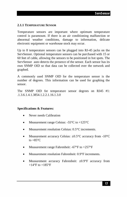
2.1.1 TEMPERATURE SENSOR
Temperature sensors are important where optimum temperaturecontrol is paramount. If there is an air conditioning malfunction orabnormal weather conditions, damage to information, delicateelectronic equipment or warehouse stock may occur.
Up to 8 temperature sensors can be plugged into RJ-45 jacks on theServSensor. Optional temperature sensors can be purchased with 15 or60 feet of cable, allowing the sensors to be positioned in hot spots. TheServSensor auto detects the presence of the sensor. Each sensor has itsown SNMP OID so that data can be collected over the network andgraphed.
A commonly used SNMP OID for the temperature sensor is thenumber of degrees. This information can be used for graphing thesensor.
The SNMP OID for temperature sensor degrees on RJ45 #1:.1.3.6.1.4.1.3854.1.2.2.1.16.1.3.0
Specifications & Features:
Never needs Calibration
Measurement range Celsius: -55°C to +125°C
Measurement resolution Celsius: 0.5°C increments.
Measurement accuracy Celsius: ±0.5°C accuracy from -10°Cto +85°C
Measurement range Fahrenheit: -67°F to +257°F
Measurement resolution Fahrenheit: 0.9°F increments.
Measurement accuracy Fahrenheit: ±0.9°F accuracy from+14°F to +185°F
18
ServSensor
18
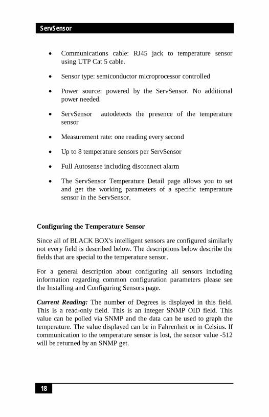
Communications cable: RJ45 jack to temperature sensorusing UTP Cat 5 cable.
Sensor type: semiconductor microprocessor controlled
Power source: powered by the ServSensor. No additionalpower needed.
ServSensor autodetects the presence of the temperaturesensor
Measurement rate: one reading every second
Up to 8 temperature sensors per ServSensor
Full Autosense including disconnect alarm
The ServSensor Temperature Detail page allows you to setand get the working parameters of a specific temperaturesensor in the ServSensor.
Configuring the Temperature Sensor
Since all of BLACK BOX's intelligent sensors are configured similarlynot every field is described below. The descriptions below describe thefields that are special to the temperature sensor.
For a general description about configuring all sensors includinginformation regarding common configuration parameters please seethe Installing and Configuring Sensors page.
Current Reading: The number of Degrees is displayed in this field.This is a read-only field. This is an integer SNMP OID field. Thisvalue can be polled via SNMP and the data can be used to graph thetemperature. The value displayed can be in Fahrenheit or in Celsius. Ifcommunication to the temperature sensor is lost, the sensor value -512will be returned by an SNMP get.

19
ServSensor
19
Status: If at any time communications with the temperature sensor arelost, the status of the temperature sensor is changed to “sensorError”.If the communication with the temperature sensor is reestablished, thestatus will be formed by comparing the Degree to the high and lowthresholds.
Degree Type: The Degree Type can be set to Fahrenheit or Celsius.When the Degree Type is changed all the threshold fields will changetheir values automatically. The ServSensor stores the thresholds forboth Celsius and Fahrenheit independently allowing you to switchbetween the two.

20
ServSensor
20
2.1.2 DUAL SENSOR (TEMPERATURE & HUMIDITY)
A new sensor from the BLACK BOX family of sensors, the dualsensor has both temperature and humidity measuring capabilities in asingle sensor. Now a single port can have two sensors, saving ports foradditional sensors. This extends the capability of the ServSensor tomeasure up to 2 temperature and 2 humidity sensing parameters, justby connecting 2 dual sensors on ServSensor, and 8 temperature and 8humidity sensing parameters, just by connecting 8 dual sensors onServSensor.
Up to 8 dual sensors can be plugged into RJ-45 jacks on theServSensor. Optional dual sensors can be purchased with 15 or 60 feetof cable, allowing the sensors to be positioned in hot spots. TheServSensor auto detects the presence of the dual sensor. Each sensor inthe dual sensor has its own SNMP OID so that data from thetemperature and the humidity sensors can be collected over thenetwork and graphed simultaneously.
When the dual sensor is plugged into the RJ45 port, the ServSensorwill auto detect the sensor, and it will display Temperature &Humidity for each RJ45 port. The user can click the links forTemperature & Humidity and can enter the settings page to configurethe sensors.
Specifications & Features:
Temperature
Measurement range Celsius: -40°C to +125°C
Measurement resolution Celsius: 0.04°C
Measurement accuracy Celsius: ±0.5°C accuracy from -10°Cto +85°C
Measurement range Fahrenheit: -67°F to +257°F
Measurement resolution Fahrenheit: 0.9°F increments.

21
ServSensor
21
Measurement accuracy Fahrenheit: ±0.9°F accuracy from+14°F to +185°F
Humidity
Measurement range: 0 to 100% Relative humidity
Sensor element wettable without damage
Resolution: 0.5 %
Accuracy at 25°C ±3%,
Working Range -20°C +60°C
Communications cable: RJ45 jack to dual sensor using UTPCat 5 cable.
Power source: powered by the ServSensor. No additionalpower needed.
ServSensor autodetects the presence of the dual sensor
Up to 8 dual sensors per ServSensor
Full Autosense including disconnect alarm
Configuring the Dual sensor
Since all of BLACK BOX's intelligent sensors are configured similarlynot every field is described below. The descriptions below describe thefields that are special to the humidity sensor.
For a general description about configuring all sensors includinginformation regarding common configuration parameters please seethe Installing and Configuring Sensors page.

22
ServSensor
22
Temperature
A commonly used SNMP OID for the temperature sensor is thenumber of degrees. This information can be used for graphing thesensor.
The SNMP OID for temperature sensor degrees on RJ45#1:.1.3.6.1.4.1.3854.1.2.2.1.16.1.3.0
Current Reading: The number of Degrees is displayed in this field.This is a read-only field. This is an integer SNMP OID field. Thisvalue can be polled via SNMP and the data can be used to graph thetemperature. The value displayed can be in Fahrenheit or in Celsius. Ifcommunication to the temperature sensor is lost, the sensor value -512will be returned by an SNMP get.
Status: If at any time communications with the temperature sensor arelost, the status of the temperature sensor is changed to “sensorError”.If communications with the temperature sensor are reestablished, thestatus will be formed by comparing the Degree to the high and lowthresholds.
Degree Type: The Degree Type can be set to Fahrenheit or Celsius.When the Degree Type is changed all the threshold fields will changetheir values automatically. The ServSensor stores the thresholds forboth Celsius and Fahrenheit independently allowing you to switchbetween the two.
Humidity
A commonly used OID for the Humidity sensor is the percentage,which can be graphed.
SNMP OID for Humidity sensor on RJ45#1
OID .1.3.6.1.4.1.3854.1.2.2.1.17.1.3.0

23
ServSensor
23
Percent: The relative Humidity Percent is displayed in this field. Thisis a read-only field. This integer OID and can be polled. The data canbe used to graph the Humidity.
Status: If at any time communications with the humidity sensor arelost, the status of the Humidity sensor is changed to “sensorError”.When communications with the humidity sensor are reestablished, thestatus will be formed by comparing the percentage to the high and lowthresholds.

24
ServSensor
24
2.1.3 WATER DETECTOR
Water can enter a building in many different ways and in some casesremain undetected, causing damage and problems to sensitiveelectronic equipment. Computer and mainframe rooms have a falsefloor and many instances of undetected water laying in these areas hasonly been detected after a problem occurred. The Water detector is animportant addition to your BLACK BOX Sensor inventory.
The Water detector is an exclusive patent pending design capable ofdetecting the presence of even distilled water. The water detectorcontains a microprocessor-controlled capacitance measuring circuitry.This is far more precise than standard commercially available waterdetectors, which measure the resistance of water. The resistance ofwater can vary depending upon the impurities in the water. Normalresistance type monitors are unable to detect the presence of distilledwater due to its high resistance.
The entire circuit is encased in epoxy allowing the water detector tofunction while submerged in water.
The water Detector detects water leaks and flooding with a WET/DRYindication in software. The ServSensor will retain any error conditionuntil it is read via an SNMP Get. Therefore if a water detectorencounters a critical condition at any time it will report that conditionbefore it returns to a normal state.
The value of the Status for the OID for switch sensors can be“normal”, “noStatus”, “critical” or “sensorError”.
For a switch type sensor on RJ45#1 the OID for the status is.
.1.3.6.1.4.1.3854.1.2.2.1.18.1.3.0
Features:
On/Off alarm signal of Water detected
Accurate, cost effective Water detecting system

25
ServSensor
25
Electronics are encased in epoxy and submersible
Electronic circuitry capable of detecting distilled water
Sensor type - open/closed contact switch
Power source: powered by the ServSensor . No additionalpower needed.
ServSensor autodetects the presence of the Water Detector
Up to 8 Water Detectors per ServSensor
Includes disconnect alarm that checks that the sensor issecurely plugged into the ServSensor
Configuring the Water Detector
Since all of BLACK BOX's intelligent sensors are configured similarlynot every field is described below. The descriptions below describe thefields that are special to the water detector.
For a general description about configuring all sensors includinginformation regarding common configuration parameters please seethe Installing and Configuring Sensors page.
Status: If the sensor is offline the status is “noStatus”. If the sensor isonline and there is no water detected the status is normal. If water isdetected then the status is critical. If at any time communications withthe Water Detector are lost, the status of the Water Detector ischanged to “sensorError”.

26
ServSensor
26
2.1.4 AIRFLOW SENSOR
The airflow sensor is a device that registers airflow in areas whereconsistent flow is needed, for example in cabinets and racks where theconsistent operation of a fan is critical to the operational safety ofelectronic equipment.
The airflow sensor is placed in the air stream, where the user canmonitor the status and the amount of flowing air. In addition to anon/off indication, it also graphs the analog values over a period oftime, although not a precision airspeed measurement device. If forexample, the fan slows down the user will be given an indication ofthe change over time. This may happen if the fan is close to failure orthe air filter is clogged. The ServSensor shows this information usinga graph via the web interface.
The value of the Status for the OID for switch sensors can be“normal”, “noStatus”, “critical” or “sensorError”.
The recognized OID for switch Sensors is 1 or 0, for RJ45 #1 it is
OID .1.3.6.1.4.1.3854.1.2.2.1.18.1.3.0
Features:
On/Off alarm signal of airflow
Airflow data graphically displayed over time
Accurate, cost effective flow sensing
2 LEDs indicate the status of Airflow and that the sensor issecurely plugged into the ServSensor
Electronics are mounted in a small plastic case
Sensor type - open / closed contact switch
Power source: powered by the ServSensor . No additionalpower needed.

27
ServSensor
27
ServSensor autodetects the presence of the airflow sensor
Up to 8 Airflow Sensors per ServSensor .
Includes disconnect alarm that checks that the sensor issecurely plugged into the ServSensor
Specifications:
Data graphically displayed via a web page
Data collection possible via any SNMP based networkmanagement system
Measurement rate: one reading each second, data loggingonce per minute
Communication cable: RJ45 jack to the ServSensor
Sensor type: Thermistor
Sensor power: line power from ServSensor
Trap information: status, sensor number, sensor description,airflow (%)
Configuring the airflow sensor
Since all of BLACK BOX's intelligent sensors are configured similarlynot every field is described below. The descriptions below describe thefields that are special to the airflow sensor.
For a general description about configuring all sensors includinginformation regarding common configuration parameters please seethe Installing and Configuring Sensors page.
Current Reading: The percentage of airflow is displayed in this field.This is a read-only field. This is an integer SNMP OID field. This

28
ServSensor
28
value can be polled via SNMP and the data can be used to graph theairflow. The values range is from 0 to 100 %
Status: If the sensor is offline the status is “noStatus”. If the sensor isonline the status will be formed by comparing the readings to the highand low thresholds. If at any time communications with the AirflowSensor are lost, the status of the airflow sensor is changed to“sensorError”.

29
ServSensor
29
2.1.5 AC VOLTAGE DETECTOR
The voltage detector is used to indicate the presence or absence of linevoltage. This is useful, for example to tell when the UPS is running onbattery power.
The AC Voltage Detector indicates an ALARM/NORMAL conditionin software and also via an LED mounted on the sensor. Voltagedetectors can detect the presence or the absence of line voltage. It isdesigned for use worldwide. There is an SNMP interface for gettingthe alarm/normal status. SNMP traps are sent when critical conditionsoccur. SNMP polling via 'get' is available to retrieve existing statusand configuration parameters. The Web browser interface is alsoavailable to display the status and configuration parameters.
When an alarm condition is activated the description and location ofthe fault can be sent via email, page or traps.
The value of the Status for the OID for switch sensors can be“normal”, “noStatus”, “critical” or “sensorError”.
The recognized OID for switch Sensors is 1 or 0, for RJ45 #1 it is
OID .1.3.6.1.4.1.3854.1.2.2.1.18.1.3.0
Specifications & Features:
Measurement range - Detects voltage at 50V AC to 250V AC
LED indicator on sensor shows if voltage present
Measurement Indication - Alarm or Normal
Communications cable - RJ45 jack to sensor using UTP Cat 5wire.
Sensor type - open / closed contact switch
Power source: powered by the ServSensor . No additionalpower needed.

30
ServSensor
30
ServSensor autodetects the presence of the voltage sensor
Measurement rate - multiple readings every second
Up to 8 AC Voltage sensors on the ServSensor
Full Autosense including disconnect alarm
Configuring the AC voltage Detector
Since all of BLACK BOX's intelligent sensors are configured similarlynot every field is described below. The descriptions below describe thefields that are special to the AC voltage sensor.
For a general description about configuring all sensors includinginformation regarding common configuration parameters please seethe Installing and Configuring Sensors page.
Status: If the sensor is offline the status is “noStatus”. If the sensor isonline and there is no AC voltage detected the status is critical. If ACvoltage is detected then the status is normal. If at any timecommunications with the AC voltage detector are lost, the status of theAC voltage detector is changed to “sensorError”.

31
ServSensor
31
2.1.6 DC VOLTAGE SENSOR
Any company or building with a large battery bank or solar powerstorage or involvement in the manufacture or storage of batteries needsthis sensor.
The DC voltage sensor is a custom sensor that works very much like adigital multimeter. The DC voltage sensor can measure voltages in therange of 0-60 volts.
One popular OID for the DC Voltage Sensors is the percentage of full-scale reading.
For a DC Voltage sensor plugged into RJ45#1 that OID is:
.1.3.6.1.4.1.3854.1.2.2.1.17.1.3.0
Specifications & Features:
Measurement range - 0-60V
Overvoltage protection. A relay within the DC Voltage sensorwill protect the ServSensor .
Status range - High Warning, Low Warning, High Critical,Low Critical
Communications cable - RJ45 jack to sensor using UTP Cat 5wire, Maximum extension cable length 100 foot withapproved low capacitance shielded cable or UTP.
Resolution - 10 bit A/D converter
Accuracy - 2LSB
Power source: powered by the ServSensor . No additionalpower needed.
ServSensor autodetects the presence of the DC voltage sensor

32
ServSensor
32
Measurement rate - multiple readings every second
Up to 8 DC voltage sensors per ServSensor
Full Autosense including disconnect alarm
Configuring the DC voltage sensor
Since all of BLACK BOX's intelligent sensors are configured similarlynot every field is described below. The descriptions below describe thefields that are special to the DC voltage sensor.
For a general description about configuring all sensors includinginformation regarding common configuration parameters please seethe Installing and Configuring Sensors page.
Current Reading: The percentage of DC voltage is displayed in thisfield. This is a read-only field. This is an integer SNMP OID field.This value can be polled via SNMP and the data can be used to graphthe airflow. The values range is from 0 to 100 %. This value dependson the jumper settings in the DC Voltage sensor box. If 10V isselected, then 0 to 10VDC is mapped to 0 to 100 %, if 20V is selected,then 0 to 20VDC is mapped to 0 to 100%.
A/D base in 1/10-volt increments: This is the minimum voltage thatthe DC Voltage sensor will output. This value in conjunction with themaximum voltage from the sensor is used to determine the percentageof the sensor.
A/D max, Range 0-40, 40 is 4 volts: This is the maximum voltage thatthe DC Voltage sensor will output. This value in conjunction with theminimum voltage from the sensor is used to determine the percentageof the sensor. So if the input jumper on the DC Voltage sensor is set to60, and the input voltage is also 60 volts then the DC Voltage sensorwill output 4 volts to the ServSensor and this is 100% of full scale.
Status: The status is formed by comparing the percentage of full scaleto the high and low thresholds. So if the A/D base is set to 0(This is 0volts) and the A/D max is set to 40(this is 4 volts) then if the actual

33
ServSensor
33
voltage from the DC Voltage sensor going into the ServSensor is 2volts, then 2 volts is 50% of full scale. In this case the scale is from 0to 4 volts and the input is 2 volts, then this is 1/2 of full scale.
The percentage of the input voltage is then compared to the thresholdsof Low Warning, High Warning, High and Low Critical that the userhas set. From this the status is then computed and emails, traps aresent if necessary.
Jumpers
The DC Voltage sensor has a jumper to set the expected range of inputvoltages. This can be set to 10, 20, 30, 40 or 60V. You should use thelowest expected settings in order to achieve the maximum resolution.

34
ServSensor
34
2.1.7 SECURITY SENSOR
The Security sensor is a magnetic on/off switch that is used as an inputto the ServSensor . Security sensors come in pairs. They are activeswitches that close when one half of the sensor is in close proximity toits mate. When the two sensor pairs are moved apart from each otherthey open. The ServSensor senses closure and opening and reports thecondition.
Security Sensors can be wired in series so that multiple sensors can usea single port on the ServSensor . There are no reasonable limits on thedistance of the security sensors from the ServSensor .
The ServSensor will retain any error condition until it is read via anSNMP get. Therefore if a security sensor encounters a criticalcondition at any time it must report that condition before it can returnto a normal state.
A popular OID for switch Sensors is the status. For RJ45 #1 it is
OID .1.3.6.1.4.1.3854.1.2.2.1.18.1.3.0
Features
On/Off alarm signal when Security Sensors switchesopen/closed
Accurate, cost effective Security System
Electronics are simple and reliable
Sensor type - open/closed contact switch
Power source: powered by the ServSensor . No additionalpower needed.
ServSensor autodetects the presence of the Security sensor
Up to 8 Security Sensors per ServSensor
Includes disconnect alarm that checks that the Security sensoris securely plugged into the ServSensor

35
ServSensor
35
Configuring the Security sensor
Since all of BLACK BOX's intelligent sensors are configured similarlynot every field is described below. The descriptions below describe thefields that are special to the Security sensor.
For a general description about configuring all sensors includinginformation regarding common configuration parameters please seethe Installing and Configuring Sensors page.
Status: If the sensor is offline the status is “noStatus”. If the sensor isonline and there are no open Sensors detected the status is normal. Ifan open Sensor is detected then the status is critical. If at any timecommunications with the Sensor are lost, the status of the SecuritySensor is changed to “sensorError”.

36
ServSensor
36
2.1.8 DRY CONTACT SENSOR
The Dry Contact sensor is a simple connection to burglar alarms, firealarms or any application that requires monitoring by the ServSensor .
These general-purpose switches can be either input or output. Whenused as an output it can source up to 20mA. You can select the outputvoltage by setting the Output Level to a Low or a High. When set toLow the pin will output 0 volts. When set as a High the pin will output5 volts.
When used as an input a switch will retain any error condition until itis read via SNMP. Therefore if a switch encounters a critical conditionat any time it must report that condition before it can return to anormal state.
Input pins can be used to detect whether or not an input switch is openor closed. In combination with external sensors, input pins can detectwhether a door or window is open or closed, if there is a waterincursion and many other conditions.
The input pins work by sensing the presence of a voltage level on aninput pin. When the switch is open the voltage is different than whenthe switch is closed.
To test a dry contact input, wire ground to one side of the switch.Ground is always pin 8 on the connector. Wire the other side of theswitch to the switch sensor. Set the “NormalState” to High. Set the“Direction” to Input. When the switch closes the input pin will beshorted to ground and the switch will change state from normal tocritical
Specifications & Features:
Measurement Indication - Alarm or Normal
Communications cable - RJ45 jack to sensor using UTP Cat 5wire.

37
ServSensor
37
Sensor type - open/closed contact switch
Power source: powered by the ServSensor . No additionalpower needed.
ServSensor autodetects the presence of the voltage sensor
Measurement rate - multiple readings every second
Up to 8 sensors on the ServSensor
Full Autosense including disconnect alarm
Configuring the Dry Contact Sensor
Since all of BLACK BOX's intelligent sensors are configured similarlynot every field is described below. The descriptions below refer to thefields that are special to the Dry contact sensor.
For a general description about configuring all sensors includinginformation regarding common configuration parameters please seethe Installing and Configuring Sensors page.
Direction: The Switch Direction can be either Input or Output. Whenset as an Input, the sensor will report its status as “normal”,“highCritical”, or “lowCritical”. The status is normal if the“NormalState” matches the current value applied to the sensor. Forexample if the “NormalState” is high and the Input to the sensor ishigh then the status is normal. The input voltage should be limited to0 to 5 volts in order to protect the sensor.
If the Direction of the sensor is Output, the sensor can be used to driveexternal equipment.
OutputLevel: The Switch “OutputLevel” can be either High/+5 Voltsor Low/GND. When set to a High, the output value of 5 volts will beapplied to the switch. When set to a Low the “OutputLevel” willdepend upon the value of Direction. If Direction is set to Output andthe “OutputLevel” is set to low, the Switch will source current in

38
ServSensor
38
order to maintain 0 Volts. If Direction is set to Input and theOutputLevel is set to low, the Switch will become tri-state.
The Output level of High will pull-up the switch even if the Directionis set to Input. However when the Switch Direction is set to Input andOutput level is set to high the Switch will output a weak pull-upcurrent. This output can be overridden by shorting the pin to ground.In this way an external switch can be determined to be open or closed.
NormalState: The Switch NormalState can be either Open/+5 Volts orClosed/GND. When set to a +5 Volts, the input value of 5 volts willcause the status to be reported as “normal”. When set to +5 Volts, theinput value of 0 volts will cause the status to be reported as“lowCritical”. When the Switch NormalState is set to a Low, theinput value of 5 volts will cause the Status to be reported as“highCritical” and the input value of 0 volts will cause the status to bereported as normal.
Information on Dry contact cables
The extension length of the dry contact twisted pairs is limited only bythe amount of electromagnetic noise in the area. So the lengths can bequite long, but long cable lengths may create occasional falsepositives. These false positives can be eliminated with the advancedfiltering of the ServSensor . You can define how long a sensor must bein the error condition before changing state from Normal to Critical.You can also define how long the sensor must remain in the Normalstate before changing from Critical to Normal.
If the dry contact cable is run outdoors where lighting strikes mayoccur or if the cable length is very long we recommend the use of theServSensor X20 or the ServSensor X60, which includes integratedopto-isolators. This will protect the ServSensor X20/X60 in case of alightning strike. This is because there is no connection to the powersupply in the ServSensor X20/X60. This is done in order to providecomplete isolation and protection to the ServSensor X20/X60.

39
ServSensor
39
Special Dry Contact settings for the X20 and X60 models of theServSensor ports 9-68.
By default, X20 and X60 will have the jumpers set as in Fig 1. forports 9-68
Fig 1 Fig 2
The simplest setup for Dry Contact inputs is as shipped. In this setuppower is provided by the ServSensor to the switches. With theServSensor providing the power, the switch has +5 Volts applied topin 1 and GND applied to pin 2. When the switch is open, the inputsenses +5, when the switch closes, the input senses GND. Noadditional external power is needed.
Figure 2 shows the jumpers set up to provide opto-isolators support.Opto-isolators provide complete electrical separation between theServSensor and the dry contact. The ServSensor is therefore protectedagainst possible large voltage spikes caused by lightning for example.

40
ServSensor
40
The user can change the settings by opening the top cover of theServSensor -X20 and changing the jumper settings according to theFig 2. This will set up the X20 for opto-isolators inputs.
NOTEDry contact ports - ports 9-68 on the X20 and X60 models of the ServSensor do nothave the Autosense feature. The user has to manually place these ports online.

41
ServSensor
41
2.1.9 4-20MA CONVERTER
The 4-20mA signal converter is used to integrate the ServSensor witha 4-20mA transmitter. 4-20mA technology is used to communicateanalog signals over long distances where electrical interference is aproblem. This solution is often used in the process control industry tocollect the analog values from a wide array of remote sensors. Currentsignals are much less susceptible to noise than voltage signals. Avoltage signal can be converted to current and then broadcast over along distance before it is converted back to voltage and read by theServSensor .
4-20mA transmitters are common in the industry for use with highquality sensors. With the 4-20mA converter these sensors can now beintegrated into the ServSensor enhancing their value with the additionof graphing, web interface, email interface, thresholds, and limits.
One popular OID for the 4-20mA Converters is the percentage of fullscale reading.
For a 4-20mA Converter plugged into RJ45#1 that OID is:
.1.3.6.1.4.1.3854.1.2.2.1.17.1.3.0
Specifications & Features:
Electronics housed in small plastic case
LED indicators on Converter show connection to ServSensor
Communications cable - RJ45 jack to sensor using UTP Cat 5wire.
Power source: powered by the ServSensor . No additionalpower needed.
ServSensor autodetects the presence of the 4-20mAConverter

42
ServSensor
42
Up to 8 4-20mA Converters on the ServSensor
Full autosense including disconnect alarm
Configuring the 4-20mA Converter
Since all of BLACK BOX's intelligent sensors are configured similarlynot every field is described below. The descriptions below describe thefields that are special to the 4-20mA Converter.
For a general description about configuring all sensors includinginformation regarding common configuration parameters please seethe Installing and Configuring Sensors page.
Current Reading: The percentage of current is displayed in this field.This is a read-only field. This is an integer SNMP OID field. Thisvalue can be polled via SNMP and the data can be used to graph theairflow. 4-20mA current is mapped to 0 to 100 %.
A/D base in 1/10 volt increments: This is the minimum voltage thatthe 4-20mA Converter will output. This value in conjunction with themaximum voltage from the sensor is used to determine the percentageof the sensor. For the 4-20mA Converter this value is automatically setto 8. In other words, when the Converter has 4mA as an input, theoutput to the A/D converter in the ServSensor will be 8 volts
A/D max, Range 0-50, 50 is 5 volts: This is the maximum voltage thatthe DC Voltage sensor will output. This value in conjunction with theminimum voltage from the sensor is used to determine the percentageof the sensor. For the 4-20mA Converter the A/D max is set to 40. Inother words, when the Converter has 20mA as an input, the output tothe A/D converter in the ServSensor will be 4 volts.
Status: The status is formed by comparing the percentage of full scaleto the high and low thresholds. The percentage of the current to fullscale is then compared to the thresholds of Low Warning, HighWarning, High and Low Critical that the user has set. From this thestatus is then computed and emails, traps are sent if necessary.

43
ServSensor
43
Below is an illustration of a typical 4-20mA settings:
Input Current Percent (%)
4.06mA 1
9.9mA 36
15.1mA 69
19.8mA 99

44
ServSensor
44
2.1.10 1-PORT POWER SWITCH
The 1-Port Power Switch allows the user Remote actuation ofelectrical devices over Internet. It provides 1 high-power SPDT 5Vrelay. It includes Metal Oxide Varistors (MOVs) and Snubber circuitsto protect the open contact of the relays from the high voltage spikes ornoise transients. It monitors the power & load and accepts a controlsignal that is sent from the ServSensor .
Applications:
Power Switching
On/Off Control
Activate Alarms
Process Control
Energy Management Systems
Specifications & Features:
Relay contacts rated at 15 A @ 220 VAC with Resistive Load8 A @ 220 VAC with Inductive Load (P.F=0.4, L/R=7ms)
Contact Material AgCdO
Max. Operating Voltage 380 VAC, 125 VDC
Max. Switching Capacity 4,000 VA, 480W with ResistiveLoad 2,000 VA, 240W with Inductive Load (P.F=0.4)
Min. Permissible Load 100mA, 5 VDC
Power Consumption 5V @ 200mA
Circuit Breaker 16 A
15Amp Fuse 380 VAC, 125 VDC

45
ServSensor
45
Communications cable - RJ45 jack to sensor using UTP Cat 5wire.
Sensor type - open/closed contact switch
Power source: powered by the ServSensor . No additionalpower needed.
ServSensor autodetects the presence of the Power RelayBoard
Up to 8 Power Relay Boards on the ServSensor
Full autosense including disconnect alarm
Metal Oxide Varistors (MOVs) and snubber circuit protectthe open contacts of the relays from high voltage spike.
4 LEDs indicate the status of the Relay, Power Supply, ACLine Voltage and AC Load Voltage.
Dimensions 65(W) x 62(H) x 15(D) mm
Operating Temperature -40°C to 85°C
Configuring the 1-Port Power Switch
Since all of BLACK BOX's intelligent sensors are configured similarlynot every field is described below. The descriptions below describe thefields that are special to the Power Relay Board.
For a general description about configuring all sensors includinginformation regarding common configuration parameters please seethe Installing and Configuring Sensors page.
Status: If the sensor is offline the status is “noStatus”. If the relay isON, then the status is “normal”, and if the relay is in OFF position,then the status is “critical”. If at any time communications with thePower Relay Board is lost, the status is changed to “sensorError”.

46
ServSensor
46
2.1.11 SMOKE DETECTOR
An important addition to security and safety: These smoke detectorsare easy to install and configure. The smoke detector must be mountedon the ceiling for maximum smoke detection.
The value of the Status for the OID for switch sensors can be“normal”, “noStatus”, “critical” or “sensorError”.
A popular OID for Smoke Detector Sensors is the status. For RJ45 #1it is
OID .1.3.6.1.4.1.3854.1.2.2.1.18.1.3.0
Features:
On/Off alarm signal of Smoke Detected
Accurate, cost effective Smoke Detector
LED indicates the status of Smoke Detector
Sensor type - open/closed contact switch
Up to 2 Smoke Detector Sensors per ServSensor
Includes disconnect alarm that checks that the sensor issecurely plugged into the ServSensor
Configuring the Smoke Detector
Since all of BLACK BOX's intelligent sensors are configured similarlynot every field is described below. The descriptions below describe thefields that are special to the Smoke Detector.
For a general description about configuring all sensors includinginformation regarding common configuration parameters please seethe Installing and Configuring Sensors page.

47
ServSensor
47
Status: If the sensor is offline the status is “noStatus”. If the sensor isonline and there is no smoke detected the status is normal. If smoke isdetected then the status is critical. If at any time communications withthe smoke detector are lost, the status of the smoke detector is changedto sensorError.
When a smoke detector is connected, the ServSensor will sense it asdry-contact sensor. The user can change the description to a smokedetector.
The Web interface settings for the smoke detector are:
Direction: Input
Normal State: Open/+5 Volts
Output Level: Low/GND

48
ServSensor
48
2.1.12 MOTION DETECTOR
The motion detector is housed in an attractive wall mountable unit andeasily added to your ServSensor network to provide security for anybuilding.
A popular OID for motion detector Sensors is the status. For RJ45#1 itis
OID .1.3.6.1.4.1.3854.1.2.2.1.18.1.3.0
Features:
On/Off alarm signal of Motion detected
Accurate, cost effective motion detecting
LED in housing indicates movement sensed
Electronics are mounted in attractive, angle adjustable wallmountable unit
Sensor type - open/closed contact switch
Power source: powered by the ServSensor . No additionalpower needed.
ServSensor autodetects the presence of the Motion Detector
Up to 2 Motion Detector Sensors per ServSensor
Includes disconnect alarm that checks that the sensor issecurely plugged into the ServSensor
Configuring the motion detector sensor

49
ServSensor
49
Since all of BLACK BOX's intelligent sensors are configured similarlynot every field is described below. The descriptions below describe thefields that are special to the motion detector.
For a general description about configuring all sensors includinginformation regarding common configuration parameters please seethe Installing and Configuring Sensors page.
Status: If the sensor is offline the status is “noStatus”. If the sensor isonline and there is no motion detected the status is “normal”. Ifmotion is detected then the status is “critical”. If at any timecommunications with the motion detector are lost, the status of themotion detector is changed to “sensorError”.

50
ServSensor
50
2.2 External Sensor IntegrationServSensor external sensor integration allows the user to integrate acustom sensor to the ServSensor while still retaining all of thefeatures of the standard sensors. This interface has the full range offunctionality including SNMP integration, email and trap generationswith adjustable limits and thresholds.
Customers have added pressure transducers, solar power monitors,battery monitors, and have integrated the ServSensor into laboratorytest equipment. For plant nurseries, hospitals and many otherapplications are possible where monitoring is essential.
This interface can be used by OEMs and engineers to create their owncustom data collection systems. The user can configure sensor inputvoltage range from 0 to 60 volts through the addition of the DCVoltage sensor directly into the ServSensor if the transducers voltagedoes not exceed 5 volts.
Readings are available in both raw data and as a percentage of fullscale. Full scale is user programmable with both the base and topvoltage from 0 to 60 volts. SNMP interface shows alarm/normal status.SNMP traps sent when status changes. SNMP polling via 'get' isavailable. Web browser interface is also available. When an alarmcondition is activated the description and location of the fault can besent via email.
All data values from the sensor are graphed overtime using theinternal memory of the ServSensor .
For more information on setting up and configuring an external sensorsee the page describing the DC Voltage Sensor.

51
ServSensor
51
3. Integration with NetworkManagement System
ServSensor is embedded with full SNMP and can integrate with anySNMP based network management systems, such as HP OpenViewNNM, IPSwitch WhatsUp Gold, CA Unicenter TNG, Tivoli, CompaqInsight Manager etc. The ServSensor comes with a MIB file that canbe easily loaded to your network management system and can receiveSNMP alerts.
By default the traps are for WhatsUp Gold style. The user can changethe traps to HP OpenView NNM or to WhatsUp Gold or both by usingthe command:
SNMPset <IP> <community> .1.3.6.1.4.1.3854.1.2.2.1.60.0 i X
where IP is the IP address of the ServSensor . community default is"public". and X can take 3 values: 1 (WhatsUp Gold style), 2 (HPOpenView Style) or 3 (both Style). By default, the X value set is 1.

52
ServSensor
52
3.1 HP OpenView3.1.1 LOADING THE MIB TO NNM
From the NNM menu press Options, then Load / Unload MIBs:SNMP. The dialog box for Loading / Unloading MIBs appears. PressLoad. A dialog box entitled: "SNMP MIB Files Not Found" appears.Press the Browse button. If you are installing this software from thefloppy disk go to A:\bin and find the sp.mib file. If you are installingthe MIB after running setup the file sp.mib can be found in the bindirectory under the installation root. For example:
"C:\Program Files\sa\bin\sp.mib"
Press open to load this MIB. Press OK to load the Trap definitions.

53
ServSensor
53
3.1.1 NNM MENU INTEGRATION
You can easily integrate hhmsagent into the NNM menu. You can addgraphing, the Web Based Monitor Application, online web baseddocumentation to the NNM Menu. This enhancement is optional but itadds a number of important features.
Because the management and documentation are web based, they canbe used on any platform such as an HP-UX box or a Sun or otherUNIX system. By adding the Web Based Manager to the NNM menuit becomes easy for the user to interact with the SNMP agenthhmsagent, regardless of his location or platform.
The NNM menu is also enhanced to add graphing. The user can graphall of the temperature or humidity values for every ServSensor .Whenever the user wants to observe temperature trends across theenterprise he can do it with a single button.
When the SNMP agent hhmsagent was installed on the NT a file wascreated to allow this menu to be added to NNM. This file is called anApplication Registration File or ARF. An ARF file is used by HP tocustomize and integrate third party applications such as thehhmsagent into NNM. The name of this file is called hhms and it islocated where you installed the agent when you ran setup.exe. Forexample a typical location would be C:\Program Files\sa\bin\sa.
In order to integrate this ARF file into NNM you must copy the file tothe proper directory so that NNM can find it when it starts. In thesimplest case of an NT running NNM that directory might beC:\OpenView\registration\C. This path would vary depending uponyour choices during installation of NNM. On a UNIX platform thepath to copy hhms to would be $OV_REGISTRATION/$LANG. Inmost cases $LANG would be C. The C would indicate that the Englishlanguage is being used. You will find other registration files in thatdirectory such as ovw, ovweb, and nnm.
After you have copied hhms to the correct directory you must restartNNM. When NNM restarts you should see hhms on the NNM menu.Under hhms you should find the menu picks to launch the Web Based

54
ServSensor
54
Manager, graph of every temperature sensor, and the status of everysensor.
The hhms file can also be customized with a standard text editor. Youmay wish to include graphs of humidity sensors or switches. Inaddition any sensor status can be visually graphed.

55
ServSensor
55
3.1.4 POLLING SNMP, THRESHOLDS AND ALARM
NNM can read the Status field to determine if any of the sensors has aproblem. Polling is the most effective method of monitoring because ifnetwork connectivity is lost, polling will reveal this failure. While theServSensor does send traps there is no guarantee that a trap will bedelivered to the monitoring station.
The network traffic generated by polling is very limited. Thetemperature sensor need only be read once every five minutes or moredepending on your needs.
Setting Up Polling
To setup polling go to the NNM toolbar and enter Options/DataCollection & Thresholds: SNMP
The dialog box appears. Enter Edit/MIB Object/New
The dialog to pick the OID to monitor appears. Click on the + toexpand the private tree. Then expand enterprises/BLACKBOX/hhmsagent. This exposes the hhmsagent mib.
You can monitor the status of an individual sensor by choosing thestatus OID for that sensor.
A second dialog appears allowing you to further refine the details ofwhat you wish to poll. Enter the IP Address of the ServSensor in theSource field. Press Add to add that data source to the list of nodes to bemonitored.
Next you can change the polling interval. For now we will enter 5s.This will cause the node to be polled every 5 seconds. This is to oftenfor a working environment. However it will help to test the hhmsagentif we poll more often. Once testing is complete we can set the pollingto a larger interval.
Set the Threshold Parameters to >= 3. This means that we will causean alarm to be triggered whenever the status is greater than or equal to

56
ServSensor
56
3. When the status is equal to 3 this means that the status of one of thesensors is at warning.
Set the Rearm value to < 3. When the status is at 2 then the sensorsare at or below normal status. When the status is at 1 then the sensorsstatus is “noStatus”. The “noStatus” status is set when the sensor isset to “offline”.
Set the Consecutive Samples to 1 for both the Threshold and TheRearm sections. Set the Rearm Value Type to Absolute. Press OK toadd this MIB Object to the collection list and return to the maindialog.
In order for this new collection to become effective you must save it.From the dialog menu enter File/Save. You are now polling the sensorStatus

57
ServSensor
57
3.1.5 TRAPS IN NNM
The ServSensor sends traps whenever their status changes. Thesetraps are defined in the file sp.mib. To act upon these traps open theEvent Configuration dialog box under the Options menu of NNM.When the Event Configuration dialog box loads, scroll down the topbox until you can select hhmsagent. The bottom list box will now listthe traps available using hhmsagent. Select a trap from the bottom listand then from the Dialog menu press Events/Modify. The ModifyEvents dialog box appears. Press Event Messages and then press Logand display in category: Choose Application Alert Alarms. Now pressActions.
You may enter a message under the popup window entry. You caninclude in the message variable binding information if the trap comesfrom the ServSensor . To include variable binding information, use $1$2 $3 $4 $5 $6 in your message. These macros are defined here.
You can now close this dialog box and go back to the EventConfiguration dialog box. Under the "File" menu choose "Save". Nowyou will see the traps in the Application Alert Alarm Browser and theAll Alarms Browser.

58
ServSensor
58
3.1.6 GRAPHING WITH NNM
The easiest way to graph is with utility xnmgraph. From a DOScommand prompt enter:
You can graph an individual temperature sensor on the ServSensor .
To graph the first temperature sensor on the ServSensor hostname10.1.1.7 enter:
xnmgraph -mib ".1.3.6.1.4.1.3854.1.2.2.1.16.1.3::0::::::" 10.1.1.7
To graph the second temperature sensor on the ServSensor hostname10.1.1.7 enter:
xnmgraph -mib ".1.3.6.1.4.1.3854.1.2.2.1.16.1.3::1::::::" 10.1.1.7
--------------------------------------------------------------------------------
The graph utility xnmgraph does not save its data. When the programexits, all data is lost. If you wish to keep long-term data you must saveit. If you have been collecting data, xnmgraph will read it in when itfirst starts.
To set up data collecting from the NNM menu, enter Options / DataCollection & Thresholds: SNMP. When the Data Collection &Thresholds: SNMP dialog loads enter Edit/MIB Collection / New.When the Collection dialog box loads Set Collection Mode: Store NoThresholds. Enter the Source hostname and add it to the Source List.Press OK to finish with this Dialog and then press File / Save to startcollecting.

59
ServSensor
59
3.1.7 USING THE MIB BROWSER
Start the browser by pressing Tools from the NNM menu, then SNMPMIB Browser. Enter the Name or Address of the SNMP ServSensor .
Enter the Community name of the ServSensor . The community nameis often set to public.
Press private to expose the mib tree under the private OID. Then pressenterprises, BLACK BOX, hhmsagent.
You will probably not use the MIB browser very much. All of theinformation available from the MIB browser is also available from theWeb Based Manager. The Web Based Manager also containsadditional features and is presented in an easier to use format.
What to do if the MIB Browser Doesn't Work
The most common cause of failure to communicate with theServSensor is the use of the wrong community string or the wronghost IP address. If you believe that those parameters are correct youcan trace the communication using a LAN analyzer such asMicrosoft's netmon.

60
ServSensor
60
3.1.8 TESTING ALARMS IN NNM
The following example tests the first temperature sensor but the idea isthe same for the other sensors. The first thing to do is to make surethat the temperature sensor is online. Press the link to the Sensors atthe top of the page. Now press the button at the left labeledTemperature. Then choose the first temperature sensor.
If the temperature sensor is plugged into the first sensor RJ-45 theAutosense will have placed this sensor online. Check to see if thesensor is online. The Status should be normal if the temperature iswithin the thresholds. If the Status is “sensorError” make sure thatthe temperature sensor is plugged into the first sensor RJ-45 jack.
While you cannot set the Status directly, you can test the sensor Status.
Setting the High Warning
In order to cause an alarm to take place you will need to set the HighWarning near to the current room temperature but high enough so thatit can go back to normal. The status of the temperature sensor will goto “highWarning” when the Degree meets or exceeds the highwarning threshold. The sensor will not go back to normal however,until the Degree goes below the high warning threshold by the Rearmamount. This is done to prevent the status from flickering.
If the room temperature is 72 and the Rearm is 2, then a good choiceto set high warning to is 76. To set the “highWarning” use the WebBased Manager. Enter 76 into the “High Warning” field and press Set.
Changing the Temperature
In order to change the temperature, warm the sensor by holding it inyou hands. The sensor is the small black plastic package at the end ofthe cable. Hold the temperature sensor until the Degree starts to rise.
To see the change on the Web Based Manager you must refresh thebrowser. Press the Temperature0 button. You will see the Degree fieldbegin to change.
61
ServSensor
61
Changing the Status
Press the Summary button in the Select a View box of the Web BasedManager. The summary will show the new Degree. When the Degreereaches the High Warning threshold the status of the temperaturesensor will change to highWarning.
Verifying Alarms
When the status changed a number of things happened to notify you ofthis change. A Trap was sent if the ServSensor was configured to sendtraps. If NNM was polling the Status an Alarm occurred.
If you have set up NNM to receive Traps from the ServSensor youwill see a Popup window appear.
If you have set up Polling in NNM verify that an alarm has actuallyoccurred by opening the Threshold Alarms Browser or the All AlarmsBrowser. There should be an alarm caused by the polled OID Statusgoing to warning that is the integer value of 3.
Resetting the Sensor Status
The temperature sensor will drift back to room temperature. You cansee this using the Web Based Manager by pressing the Summary Viewto refresh the browser. You can also enter a value in the Auto RefreshBrowser Interval field. This will cause the browser to automaticallyrefresh itself.
You will see the Degree change. When the Degree plus the Rearmamount is less than the High Warning threshold the status of thesensor and the value of the Status OID will change back to normal.When this Status changes you will again be notified with a Trap. IfNNM was polling the Status an Alarm will occur.
Resetting Thresholds

62
ServSensor
62
If you changed the NNM polling interval, go back to the NNM DataCollection and Threshold dialog and reset the polling interval to 1minute.
3.2 Whats UP Gold
3.2.1 MONITORING SERVSENSOR WITH WHATSUP GOLD
Setting up the MIB identifier
WhatsUp Gold provides a command line program named mibextra.exeused to update the MIB and the trap information that WhatsUp Goldreferences. The program is located in the directory where WhatsUpGold is installed.
To run the MIB extractor: at the command prompt enter:
WhatsUp> mibextra directory_name\sp.mib
NOTEIf the mib extractor returns “failed to open file” error, the MIB file sp.mib hasdependencies. These dependency files are listed in the import section of the MIB fileand must be provided in the same directory as the MIB file.
Now see next topic - Browsing SNMP variables

63
ServSensor
63
3.2.2 BROWSING SNMP VARIABLES
The SNMP device needed to be monitored must be created and addedto a network map, this network map could be the existing one or onenewly created.
1. Creating a blank network map
1.1 From the File menu of WhatsUp Gold, select 'New Map Wizard'
1.2 Choose 'Create a blank map'
Press the Finish button. The network map editor window will come up( see Figure 1. )
Figure 1 Network Map Editor
2. Creating and adding an SNMP device to the network map
2.1 Right-click the blank area (the right pane).

64
ServSensor
64
2.2 Select New Device, and select "Lanbox". A "Lanbox" icon willappear on the map.
3. Configuring the newly created SNMP device
3.1 Double click the icon to open the item properties dialog box.
3.2 On the left pane, select General (see Figure 2).
Figure 2 General Property page
3.3 Fill out the form.
All fields are described below:
- Display name: this identifies the SNMP device (i.e. ServSensor ).
- Type: this is the device type (i.e. Lanbox).
- Polling Method: this should be ICMP since ServSensor supportsonly this polling method.
65
ServSensor
65
- Poll using: this could be either Hostname or IP Address. If the IPaddress of the SNMP device was assigned by DHCP server, Hostnamewould be the suitable choice.
- Host name: this could be the host name that can be resolved to an IPaddress of the device, or it could be just the IP address of theServSensor .
- IP Address: this must be the IP address of the ServSensor .
- Info Line1 and Info Line2: information entered in these two fieldswill be included in notification messages such as SMS and email.
3.4 On the left pane, select SNMP.
3.5 Enable SNMP Manageable Device as show in Figure 3.
3.6 Fill out all fields including Read Community, Write Community,and Device Object ID.
These fields are described below:
- Read Community: this is the password used for SNMP readpermission for the ServSensor . The default password is public.
- Write Community: this is the password used for SNMP writepermission for the ServSensor . The default password is public.
- Device Object ID: this is the SNMP object identifier for the device.This identifier is used to access a device and read other SNMP data.The device object ID of ServSensor is 1.3.6.1.4.1.3854.1.2.2.1.1.
3.7 Press the OK button to close the window

66
ServSensor
66
Figure 3 SNMP Property page

67
ServSensor
67
3.2.3 GRAPHING THE VALUES OF SNMP VARIABLES
WhatsUp Gold provides a graphing utility named SNMP Graph. Userscould select one or more SNMP variables to show a real-time graph oftheir values, Moreover the utility can graph the change between thelast and the current value of a SNMP variable as well as the averagechange per second in the values of a SNMP variable.
1. Launching SNMP Graph utility
1.1 From SNMP browser, right-click a desired SNMP variable to bemonitored on the right pane of the browser as show in Figure 5.
1.2 Select Monitor to open SNMP Graph (see Figure 6).
Figure 5 SNMPbrowser

68
ServSensor
68
Figure 6 SNMP Graph Utility
2. Setting the item graphing options
By default, the utility graphs the change between the last and thecurrent value of a SNMP variable.
The steps below show how to set the utility to graph the reportedvalues of the SNMP variable.
2.1 Right-click on the IP address column of the desired SNMP variableas show in Figure 6.
Note: There are four menu items including Add (add another SNMPvariable), Delete (delete the selected variable), Properties (set graphingoptions) and View Values (view the raw data used to generate thegraph for the selected SNMP variable).
2.2 Select Properties to open Graph Item Properties dialog box (seeFigure 7). The description of some interesting properties is describedbelow:
- Host: this is the IP address of the SNMP device.

69
ServSensor
69
- Community Name: this is the password used for SNMP readpermission.
- Item and Instance: both are used to form the OID of the SNMPvariable.
- Absolute values: when it is selected, the utility graphs the reportedvalue of the SNMP variable.
- Auto Scale: when it is selected, the graph scale for the SNMPvariable is determined by the utility.
- Allow negative values: when it is selected, the utility allows negativevalues to be graphed.
Figure 7 graph Item properties
2.3 Select Absolute values as show in Figure 7.
2.4 Press OK button to apply the setting and close the dialog box.

70
ServSensor
70
3. Setting the graph options
3.1 From the Graph menu items of SNMP Graph utility (Figure 6),select Properties to open Graph Option dialog box shown in Figure 8.
Figure 8 Graph options dialog box
3.2 Set up the properties
- Set Interval (seconds) to 3. This is the time interval at which theutility gets the value of the SNMP variable from the SNMP device.
- In Vertical group box, set the Maximum to 180. This determines thehighest value on the x-axis scale.
- In Horizontal group box, set Maximum to 100 and Minimum to 50.The Maximum and Minimum determine the highest and lowest valueon the y-axis scale respectively.
3.3 Press OK to apply the new setting and close the dialog box.

71
ServSensor
71
3.2.4 RECEIVING SNMP TRAPS FROM THE SERVSENSOR
First, users have to configure the ServSensor to send SNMP traps tothe machine running WhatsUp Gold. This can be configured throughthe web interface of the ServSensor .
1. Setting up the ServSensor to send traps
1.1 Select the Traps Tab to go to the Traps page
1.2 Select Send Traps ON via selection box, enter the Destination IP ofthe WhatsUp Gold Host and enter the Community. Then press Set
After that do the following steps to set up WhatsUp Gold.
2. Enabling the SNMP Trap Handler
2.1 From the Configure menu of WhatsUp Gold, select ProgramOptions to open Program Option dialog box.
2.2 On the left pane of the dialog box, click Event Servers icon.
2.3 On the right pane of the dialog box, select SNMP Trap.
2.4 Press Configure button to open Configure SNMP Trap ServerProperties dialog box shown in Figure 9.

72
ServSensor
72
Figure 9 Configure SNMP Trap Server Properties
2.5 Select Listen for messages on port.
2.6 Fill out a listening port number (the default value is the standardSNMP trap Port is 162).
2.7 Press OK button on Configure SNMP Trap Server Propertiesdialog box
2.8 Press OK button on Program Options dialog box.
3. Assigning SNMP trap events to the ServSensor
3.1 Double click the ServSensor icon on the network map to open theitem properties dialog box shown in Figure 2.
3.2 On the left pane, select Events.
3.3 Press Add button located on the right pane. The device eventproperties dialog box will come up (see Figure 10).

73
ServSensor
73
Figure 10 Device Event Properties dialog box
3.4 From Event Type list box, select SNMP trap.
3.5 From Event list box, select spTemperature1Status
3.6 Press OK button to close the dialog box.
3.7 Repeat setup 2.3 to 2.6 to add all spTemperature2Status tospTemperature8Status as show in Figure 11.

74
ServSensor
74
Figure 11 Trap events assigned to the ServSensor
4. Defining Email notifications
There are several notifications supported by WhatsUp Gold includingBeeper, Group, Pager, Programs, SMS, SMTP Mail, Sound, andWinPopup. The following steps guide how to configure SMTP Mail.
4.1 From Configure menu of WhatsUp Gold, select NotificationLibrary.
4.2 Select SMTPMail.
4.3 Press New button to open New SMTP Notification dialog boxshown in Figure

75
ServSensor
75
Figure 12 New SMTP Notification dialog box
4.4 Filling out the form
- Display Name: it is a unique name to identify the email notification,for example "Mail to Admin".
- Mail Server: it is the IP address of your SMTP server.
- To: it could be one or more email addresses. Each email address isseparated by a comma.
- From: it is an email address that will be the sender of an emailnotification.
- Subject: it is the subject of an email notification
NOTENotification message variables are usually used in the subject and the body field(refer to the WhatsUp Gold documentation for further detail).

76
ServSensor
76
4.5 Press OK button to close the dialog box.
5. Setting up notifications for SMTP trap events
5.1 On the left pane of the item properties dialog box, select Alerts.
5.2 Select Enable alerts and Enable logging.
5.3 Press Add button to open Add Alerts dialog box shown in Figure13.
5.4 In Notification box, select SMTPMail and Mail to Admin.
5.5 In Trigger box, enter 9999.
5.6 Select Send alert even if console response.
5.7 Select On event.
5.8 Press Select Events button to open Active Event dialog box shownin Figure 14.
5.9 Select “Only these specific events listed on this device” andactivate desired trap events by clicking the check box corresponding tothem. WhatsUp Gold will send a notification when it receives anactive trap event. In figure 14, the first three events are active.
NOTEA notification will also be sent if the ServSensor misses the number of pollsspecified in the trigger box. To disable this particular notification, set the triggernumber to 9999.

77
ServSensor
77
Figure 13 Add Alerts dialog box
Figure 14 Active Events dialog box

78
ServSensor
78
3.3 MRTG - free data graphing3.3.1 MRTG INSTALLATION
The ServSensor is fully compatible with MRTG. You will need to doto download and install MRTG and then create a configuration script.The configuration script will instruct MRTG how to pull the data fromthe ServSensor via SNMP. MRTG will then produce an HTML filegiving you graphs for daily, weekly, monthly, and yearly statistics.
This HTML file can be recreated at periodic intervals by MRTGproviding a live, up to date graph. This HTML file is often publishedby a web server giving the latest graphs to the all users in theenterprise.
How do I install MRTG?
MRTG can be downloaded from www.mrtg.org. This site hasinstructions to download MRTG and install it. MRTG will run bothon Linux & Windows platforms.
After installation, you need to create a configuration file that willgather information from the ServSensor and plot a graph. Below is aminimal template that can be used to gather data from the ServSensor.
Template:
/**********************************************/
workdir: /www/MRTG
NoMib2: Yes
Target[CONFIG-NAME]:1.3.6.1.4.1.3854.1.2.2.1.16.1.3.0&.1.3.6.1.4.1.3854.1.2.2.1.17.1.3.1:[email protected]
MaxBytes[CONFIG-NAME]: 1000

79
ServSensor
79
Options[CONFIG-NAME]: growright, nopercent, gauge
Title[CONFIG-NAME]: /*Title to display in the html page*/
PageTop[CONFIG-NAME]: /*Page heading */
YLegend[CONFIG-NAME]: Deg C / % Hum
ShortLegend[CONFIG-NAME]:  
Legend1[CONFIG-NAME]: Temperature
Legend2[CONFIG-NAME]: Relative Humidity
LegendI[CONFIG-NAME]: Temperature  in °C 
LegendO[CONFIG-NAME]: Humidity  in % 
/**********************************************/
The CONFIG-NAME is the base name for files that will be generatedby MRTG, when the above script is run. More details on theconfiguration file syntax can be found in the link below:
http://people.ee.ethz.ch/~oetiker/webtools/mrtg/mrtg-reference.html
You can add more configurations to the above template to customize itfor your needs.
The above sample gives the graphs for the Temperature Sensorconnected to port1 and humidity sensor on port2 of the ServSensorwith IP 192.168.0.205 and community as public.
Below is a list of OID’s for temperature & humidity sensors. To findout an OID connected to a particular port, the user has to read the lastdigits of the OID. In the web-interface, the ports are numbered from 1to 8 and the corresponding OID last digits are from 0 to 7.

80
ServSensor
80
Temperature OID's:
.1.3.6.1.4.1.3854.1.2.2.1.16.1.3.0 #this is the temperature 1
.1.3.6.1.4.1.3854.1.2.2.1.16.1.3.1 #this is the temperature 2
.1.3.6.1.4.1.3854.1.2.2.1.16.1.3.2 #this is the temperature 3
.1.3.6.1.4.1.3854.1.2.2.1.16.1.3.3 #this is the temperature 4
.1.3.6.1.4.1.3854.1.2.2.1.16.1.3.4 #this is the temperature 5
.1.3.6.1.4.1.3854.1.2.2.1.16.1.3.5 #this is the temperature 6
.1.3.6.1.4.1.3854.1.2.2.1.16.1.3.6 #this is the temperature 7
.1.3.6.1.4.1.3854.1.2.2.1.16.1.3.7 #this is the temperature 8
Humidity OID's:
.1.3.6.1.4.1.3854.1.2.2.1.17.1.3.0 #this is the humidity 1
.1.3.6.1.4.1.3854.1.2.2.1.17.1.3.1 #this is the humidity 2
.1.3.6.1.4.1.3854.1.2.2.1.17.1.3.2 #this is the humidity 3
.1.3.6.1.4.1.3854.1.2.2.1.17.1.3.3 #this is the humidity 4
.1.3.6.1.4.1.3854.1.2.2.1.17.1.3.4 #this is the humidity 5
.1.3.6.1.4.1.3854.1.2.2.1.17.1.3.5 #this is the humidity 6
.1.3.6.1.4.1.3854.1.2.2.1.17.1.3.6 #this is the humidity 7
.1.3.6.1.4.1.3854.1.2.2.1.17.1.3.7 #this is the humidity 8

81
ServSensor
81
This link also gives you the sample configuration files similar to theabove template, which is used to gather data from the ServSensor .
Any sensor producing a graphical data in the ServSensor can beconfigured in MRTG.

82
ServSensor
82
3.3.2 SAMPLE MRTG GRAPHS
`Daily' Graph (5 Minute Average)
`Weekly' Graph (30 Minute Average)
`Monthly' Graph (2 Hour Average)
`Yearly' Graph (1 Day Average)

83
ServSensor
83

84
ServSensor
84
3.4 Frequently used OID'sHere you can find the frequently used OID's for the temperature,humidity & switch type sensors. To find out an OID connected to aparticular port, the user has to read the last digits of the OID. In theweb-interface, the ports are numbered from 1 to 8 and thecorresponding OID last digits are from 0 to 7.
Temperature OID's:
.1.3.6.1.4.1.3854.1.2.2.1.16.1.3.0 #this is the temperature 1
.1.3.6.1.4.1.3854.1.2.2.1.16.1.3.1 #this is the temperature 2
.1.3.6.1.4.1.3854.1.2.2.1.16.1.3.2 #this is the temperature 3
.1.3.6.1.4.1.3854.1.2.2.1.16.1.3.3 #this is the temperature 4
.1.3.6.1.4.1.3854.1.2.2.1.16.1.3.4 #this is the temperature 5
.1.3.6.1.4.1.3854.1.2.2.1.16.1.3.5 #this is the temperature 6
.1.3.6.1.4.1.3854.1.2.2.1.16.1.3.6 #this is the temperature 7
.1.3.6.1.4.1.3854.1.2.2.1.16.1.3.7 #this is the temperature 8
Humidity OID's:
.1.3.6.1.4.1.3854.1.2.2.1.17.1.3.0 #this is the humidity 1
.1.3.6.1.4.1.3854.1.2.2.1.17.1.3.1 #this is the humidity 2
.1.3.6.1.4.1.3854.1.2.2.1.17.1.3.2 #this is the humidity 3
.1.3.6.1.4.1.3854.1.2.2.1.17.1.3.3 #this is the humidity 4
.1.3.6.1.4.1.3854.1.2.2.1.17.1.3.4 #this is the humidity 5
.1.3.6.1.4.1.3854.1.2.2.1.17.1.3.5 #this is the humidity 6

85
ServSensor
85
.1.3.6.1.4.1.3854.1.2.2.1.17.1.3.6 #this is the humidity 7
.1.3.6.1.4.1.3854.1.2.2.1.17.1.3.7 #this is the humidity 8
Switch Type sensors:
The type of switch can be found using the following OID's:
.1.3.6.1.4.1.3854.1.2.2.1.18.1.9.0
.1.3.6.1.4.1.3854.1.2.2.1.18.1.9.1
.1.3.6.1.4.1.3854.1.2.2.1.18.1.9.2
.1.3.6.1.4.1.3854.1.2.2.1.18.1.9.3
.1.3.6.1.4.1.3854.1.2.2.1.18.1.9.4
.1.3.6.1.4.1.3854.1.2.2.1.18.1.9.5
.1.3.6.1.4.1.3854.1.2.2.1.18.1.9.6
.1.3.6.1.4.1.3854.1.2.2.1.18.1.9.7
The values of this OID and corresponding sensors are:
Value Sensor Type
4 Water
6 Security
8 Airflow
10 Dry Contact
12 Relay
13 Voltage

86
ServSensor
86
14 Motion Detector
The switch status can be found out using the following OID's:
.1.3.6.1.4.1.3854.1.2.2.1.18.1.3.0 #this is the switch 1
.1.3.6.1.4.1.3854.1.2.2.1.18.1.3.1 #this is the switch 2
.1.3.6.1.4.1.3854.1.2.2.1.18.1.3.2 #this is the switch 3
.1.3.6.1.4.1.3854.1.2.2.1.18.1.3.3 #this is the switch 4
.1.3.6.1.4.1.3854.1.2.2.1.18.1.3.4 #this is the switch 5
.1.3.6.1.4.1.3854.1.2.2.1.18.1.3.5 #this is the switch 6
.1.3.6.1.4.1.3854.1.2.2.1.18.1.3.6 #this is the switch 7
.1.3.6.1.4.1.3854.1.2.2.1.18.1.3.7 #this is the switch 8
To set a switch output to high:
The OID's are:
.1.3.6.1.4.1.3854.1.2.2.1.18.1.8.0
.1.3.6.1.4.1.3854.1.2.2.1.18.1.8.1
.1.3.6.1.4.1.3854.1.2.2.1.18.1.8.2
.1.3.6.1.4.1.3854.1.2.2.1.18.1.8.3
.1.3.6.1.4.1.3854.1.2.2.1.18.1.8.4
.1.3.6.1.4.1.3854.1.2.2.1.18.1.8.5
.1.3.6.1.4.1.3854.1.2.2.1.18.1.8.6
.1.3.6.1.4.1.3854.1.2.2.1.18.1.8.7

87
ServSensor
87
This is helpful for remote actuation of a device, when a certainparameter is set.
Example: if a temperature sensor is connected on port 1 and a drycontact cable is connected on port 2, and the temperature exceedsthreshold, then the management software can send an SNMP Set tothe dry contact on port 2 with the following command:
SNMPset 192.168.0.100 public .1.3.6.1.4.1.3854.1.2.2.1.18.1.8.1 i 1
The i denotes an integer value
i can take 2 values: 1 = output high, 2 = output low
This will make the dry contact pins output a +5V which can turn on arelay.
For other examples, please see the file spinit.bat located at\utilities\mib in the help CD.
For full definitions of all OIDs and their possible values please see thefile sp.mib

88
ServSensor
88
3.5 ServSensor MIB
SP.MIB
This MIB file is given along with this software to load all the MIBfiles compatible with HP OpenView, CA Unicenter TNG, UC DavisSNMP package, Veritas etc.
This file is located in the folder \utilities\mib\ in the help CD providedalong with the product.

89
ServSensor
89
4. SNMP
The ServSensor is fully compliant with SNMP V1 and has been testedon a number of different platforms including Hewlett Packard andtheir OpenView platform, Computer Associates and their TNGplatform, Cabletron and their Spectrum platform, IBM Tivoli,Veritas, WhatsUp Gold, Microsoft SNMP, as well as various UNIXsystems including Linux, BSD, and Sun.
The MIB for the ServSensor is available and is called sp.mib ThisMIB can be loaded into a MIB browser and used to access the agent.

90
ServSensor
90
4.1 MIB on the ServSensorFor a formal definition of a specific OID consult the file sp.mib
You can use standard SNMP tools to access the MIB on theServSensor . For example the utility SNMPutil can be used from thecommand line of a NT to get information from the ServSensor .
There are also utilities from UCD that we can send upon request. Withthese standard SNMP utilities you can set and get SNMP parametersfrom a script file.
For example the following line gets the first temperature sensor:
SNMPget 10.1.1.7 public .1.3.6.1.4.1.3854.1.2.2.1.16.1.3.0
The following line gets the second temperature sensor:
SNMPget 10.1.1.7 public .1.3.6.1.4.1.3854.1.2.2.1.16.1.3.1
The programs SNMPget.exe and SNMPset.exe are located in the folder\utilities\mib\ in the help CD provided along with the product.
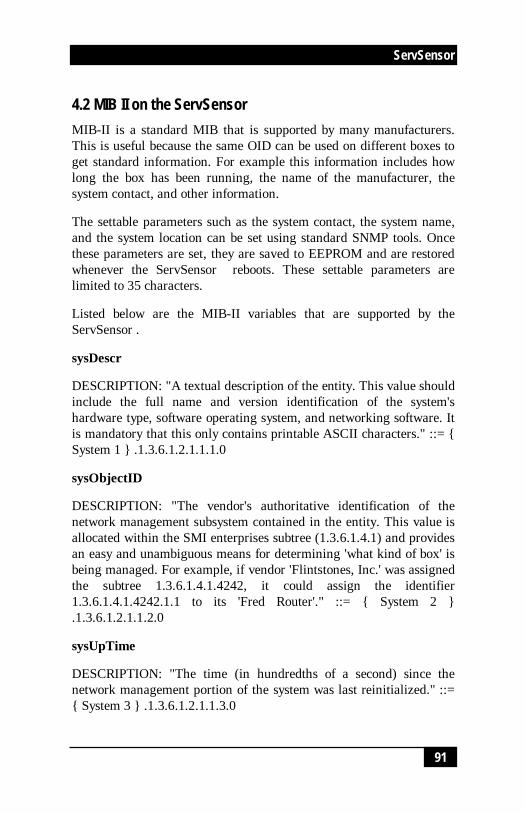
91
ServSensor
91
4.2 MIB II on the ServSensorMIB-II is a standard MIB that is supported by many manufacturers.This is useful because the same OID can be used on different boxes toget standard information. For example this information includes howlong the box has been running, the name of the manufacturer, thesystem contact, and other information.
The settable parameters such as the system contact, the system name,and the system location can be set using standard SNMP tools. Oncethese parameters are set, they are saved to EEPROM and are restoredwhenever the ServSensor reboots. These settable parameters arelimited to 35 characters.
Listed below are the MIB-II variables that are supported by theServSensor .
sysDescr
DESCRIPTION: "A textual description of the entity. This value shouldinclude the full name and version identification of the system'shardware type, software operating system, and networking software. Itis mandatory that this only contains printable ASCII characters." ::= {System 1 } .1.3.6.1.2.1.1.1.0
sysObjectID
DESCRIPTION: "The vendor's authoritative identification of thenetwork management subsystem contained in the entity. This value isallocated within the SMI enterprises subtree (1.3.6.1.4.1) and providesan easy and unambiguous means for determining 'what kind of box' isbeing managed. For example, if vendor 'Flintstones, Inc.' was assignedthe subtree 1.3.6.1.4.1.4242, it could assign the identifier1.3.6.1.4.1.4242.1.1 to its 'Fred Router'." ::= { System 2 }.1.3.6.1.2.1.1.2.0
sysUpTime
DESCRIPTION: "The time (in hundredths of a second) since thenetwork management portion of the system was last reinitialized." ::={ System 3 } .1.3.6.1.2.1.1.3.0

92
ServSensor
92
sysContact
DESCRIPTION: "The textual identification of the contact person forthis managed node, together with information on how to contact thisperson." ::= { System 4 } .1.3.6.1.2.1.1.4.0
sysName
DESCRIPTION: "An administratively-assigned name for thismanaged node. By convention, this is the node's fully-qualifieddomain name." ::= { System 5 } .1.3.6.1.2.1.1.5.0
sysLocation
DESCRIPTION: "The physical location of this node (e.g., 'telephonecloset, 3rd floor')." ::= { system 6 } .1.3.6.1.2.1.1.6.0
sysIfNumber
DESCRIPTION: "The Number of Interfaces this device supports" ::= {interfaces 1 } .1.3.6.1.2.1.2.1.0
sysIfIndex
DESCRIPTION: "Unique Index for this entry" ::= { interfaces 2.1.1 }.1.3.6.1.2.1.2.2.1.1.0 1,3,6,1,2,1,2,2,1,1,0

93
ServSensor
93
4.3 SNMP TrapsThe implementation of Traps on the ServSensor is complete and fullyfeatured. Features include a 35-byte description field for every sensorwithin the ServSensor . This includes a different description field forevery possible sensor plugged into every possible port.
Every sensor has programmable limits and thresholds. A different trapmessage is sent for each sensor type such as temperature, humidity,switch, etc. The trap messages include 6 var bind fields that includethe current sensor status (normal, highWarning, highCritical,lowWarning, lowCritical, sensorError), the current sensor value, thelevel exceeded, the sensor index, the sensor name, the sensordescription.
All of the trap information can be included in messages that youformat. The description of the sensor and its current value are useful increating meaningful messages.
The trap system supports the two trap destinations.
4.4 Trap thresholdsThe ServSensor checks the thresholds of each of its alarms once perTrap Poll Interval (twice per second). The ServSensor only checks thestatus of those sensors that are online.

94
ServSensor
94
4.5 Trap Var Bind InformationWhen the ServSensor sends traps it uses a different trap for everysensor. For example when a temperature sensor trap is sent, anenterprise trap of 6 and a specific type of 100 plus the port number ofthat sensor is used. When the humidity trap is sent an enterprise trapof 6 and a specific type of 200 plus the port number is used. When theswitch trap is sent an enterprise trap of 6 and a specific type of 300plus the port number is used. All of the switch sensors such as thewater detector, voltage monitor, and security sensor share the switchtrap.
In addition to the trap type information, Variable Bind Information isalso included. Six Var bind fields are attached to the trap. These fieldsare described in order:
1. The status of the sensor. This can be:
noStatus(1),
normal(2),
highWarning(3),
highCritical(4),
lowWarning(5),
lowCritical(6),
sensorError(7)
2. The sensor value. For a temperature sensor this would be thedegree. For a humidity sensor this would be the relative humidity. Fora switch it would be a 1 or a 0.
3. Sensor Level Exceeded. The threshold value that was exceeded.
4. Sensor Index. The RJ-45 jack that the sensor is plugged into. Thiswill be 0 or 1 for RJ-45 1 or 2.

95
ServSensor
95
5. Sensor Name. For example temperature0, humidity1, water1.
6. Sensor Description. The description that was previously entered intothe ServSensor for that sensor.

96
ServSensor
96
4.6 Community String
By Default the community string in "public". This is also thepassword for the User and Administrator. When the Administratorpassword is changed, that will become the new community string forSNMP read/write operations. If the User password is changed, thatpassword becomes the new community string for SNMP readoperations. That is the password for Administrator or User can be usedas the community string for SNMP read/write operations, and only theAdministrator password can be used for the SNMP write operations.

97
ServSensor
97
5. Web based User Interface
The best way to get to know the ServSensor is through the Web BasedManager.
NOTEJavascript needs to be enabled in the Web Browser for the ServSensor WebInterface to work.
The Web Based Manager has a list of functions reachable by pressingthe links at the top of the web page. The links are described below:
Summary
Look at the Summary View by pressing that link at the top of the page.This section shows the summary status of all the sensors that areonline. This gives a single page overview of the sensors in theServSensor that you have placed online.
You can leave your browser on the summary page and set the AutoRefresh Browser Interval so that the page continually refreshes itselfwith the latest values.
Sensors
The Sensors View is used to show and change information for everysensor in the ServSensor. This section allows you to drill down intothe sensor. From there you can set the Description, Thresholds, andmany other values.
Traps
The ServSensor can send traps to two different trap collectors. Youcan set up the traps using this page.

98
ServSensor
98
You can send mail and pages when thresholds for alarms are reached.
System
The System page displays information for the ServSensor . From hereyou can view the MIBII variable such as System Description, SystemContact, System Name. You can change the set and get passwords andmore.
Help
This is a link to the web based help that is available using the Internet

99
ServSensor
99
5.1 Login PageServSensor comes with an advanced login feature with two levels ofpassword protection. There is a read only user password and aread/write administrator password to protect the device configuration.The password settings are encrypted and saved into the device toprevent unauthorized access.
Open your browser window, type the IP address of ServSensor andenter, the Login Page is then loaded.
The login page will be skipped if you have chosen to not usepasswords. To use passwords or to enter a new password, go to the"System" menu, and password settings. This will force later logins togo through the Login Page.
Login as User
The User login allows you to access the system, but does not allowchanging any settings. You can navigate all the pages.
The default "User" password is "public"
Login as Administrator
Administrator login gives you all privileges to change the systemconfigurations.
The default "Administrator" password is "public"
To change the password, login as "Administrator" with defaultpassword, go to "System" menu on the web page and type your new"User" password and "Administrator", click on the "Set" button.
You can see the current login status from the top right corner of theweb page and you can log off the system by clicking "Log off" link.

100
ServSensor
100

101
ServSensor
101
5.2 Summary PageThe summary page gives you a convenient single page overview of allthe sensors that are online. Info on each sensor includes the Port,Type, Description, Reading, Status, and Graph link, and Auto Refresh.
These features are explained in detail below.
Auto Refresh Web (sec.): The Summary page can be automaticallyrefreshed by entering the desired period in seconds in the Auto RefreshWeb (sec.) field. Enter the number of seconds and then click the"Start" button next to the field.
If the page is rapidly updating it may be difficult to enter a new value.In that case you should stop the browser from refreshing by pressingStop in the web browser. You can now enter a new refresh value. Todisable refresh enter 0 for the refresh period and press the Summarylink at the top of the page.
Port: This is the Autosense RJ45 sensor port that the sensor may beplugged into. It is numbered from 1 to 2 in ServSensor and 1 to 8 inServSensor 8.
Type: This field shows the type of sensor, for example temperature,humidity, security. The ServSensor can autodetect any intelligentsensors from BLACK BOX and this field will be updated accordingly.
Description: The description of the field is the value entered in the"Sensor settings" page.
NOTEFor a shortcut to configure the sensor, click on the link to go to the settings page ofeach sensor
Reading: Reading gives the current sensor reading.
Status: The Status field shows the status of each sensor plugged intothe ServSensor . The value may be "Normal" " Warning" or "Criticalor Not Plugged in".

102
ServSensor
102
View Graph: Every temperature sensor, humidity sensor, DC Voltageand Airflow sensor can be graphed simultaneously. To view theirgraph press the link "View Graph" next to the sensor.
Sys Log: System log gives the status of each and every event thatoccurred at a particular date and time. System log will help you toview the events generated by the device. You can navigate using theFirst, Previous, Next and Last button to review the events. The SysLog can also be linked to a remote Sys Log receiver.

103
ServSensor
103
5.3 Sensors settingThis page use for setting the any sensor properties. For a generaldescription about configuring all sensors including informationregarding common configuration parameters please see the Installingand Configuring Sensors page.

104
ServSensor
104
5.4 Graphing
The graphing capabilities of the ServSensor are designed forfunctionality: they are simple and easy to use. However if greaterflexibility is desired you should consider the use of third partygraphing tools. BLACK BOX has written a data capture utility that itincludes for no charge on the CD ROM included with the system. Thisutility records the value of a sensor on a host system. It is then possibleto use a large number of third party tools to graph this data.
How much data can be graphed?
The ServSensor has enough memory to save 8640 data points for eachsensor. If data is recorded every 15 minutes, there is enough data todisplay measurements for 90 days. If the recording is made everyminute, there is enough memory to hold data for 6 days.
Note: Whenever power is recycled the data logging is reinitializedand all previous data is lost.
Whenever a sensor is taken off-line and then placed back online thedata logging is reinitialized and all previous data is lost.
High and low values
The High value and the low values for every period are displayed. Ifthe sensor is removed and a sensorError is observed, then no valuewill be recorded at that time.
Time Accuracy
The time is determined by a battery-backed clock in the ServSensor .
Data averaging
The data recorded is the average for the high and low value duringthat period. The data is clipped at 0 and 100. Any value over 100 willdisplay as 100. Any value less than 0 will display as 0.

105
ServSensor
105
Click on a time to zoom in
There is too much data to display all of it on a single page. Thereforethe data is averaged before being shown. When you click on a time tozoom in on, all data for that period of time is displayed.

106
ServSensor
106
5.5 Traps Setting
The ServSensor can send trap message to two different hosts.Whenever the status changes for a sensor that is online a trap messagecan be sent.
A different trap message is sent for each sensor type such astemperature, humidity, and switch. The trap messages include 6 varbind fields that include the current sensor status (normal,highWarning, highCritical, lowWarning, lowCritical, sensorError),the current sensor value, the level exceeded, the sensor index, thesensor name, the sensor description.
If trap is not needed it should be turned off. This will reduce networktraffic and allow the ServSensor to operate faster. If you do not need itwe suggest that you disable the traps resend feature.
To configure Traps click the link at the top of the web page labeled"Traps".
Send Trap: Turn Traps on or off with this choice. Use the list box topick either On or Off. Press the Set button to implement your choice.
Destination IP: This is the IP address of the destination host that willcollect this trap.
Community: This is the Community of the host that will receive thistrap. This is often set to "public".
Resend Warning and Error Traps: You can choose to have trapsresent on a periodic interval. This may be a good idea because trapmessages are not guaranteed to be delivered. Traps are based on theUDP communications protocol. Each packet is transmitted, but there isno check to see if they were lost or garbled.
Resend Interval (seconds): You can set the period between which awarning or error trap messages will be re-transmitted. The minimumperiod is 10 seconds. This time period is also used when resendingemail messages.

107
ServSensor
107
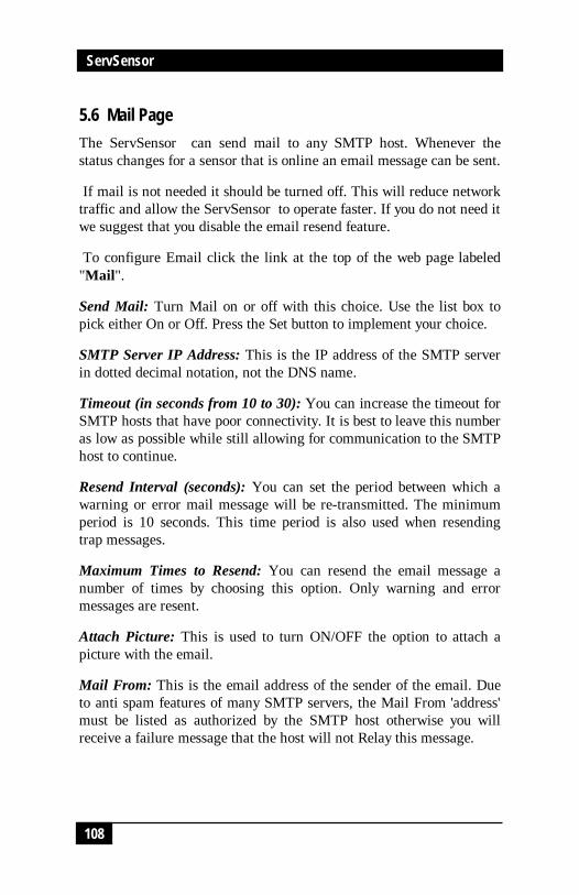
108
ServSensor
108
5.6 Mail PageThe ServSensor can send mail to any SMTP host. Whenever thestatus changes for a sensor that is online an email message can be sent.
If mail is not needed it should be turned off. This will reduce networktraffic and allow the ServSensor to operate faster. If you do not need itwe suggest that you disable the email resend feature.
To configure Email click the link at the top of the web page labeled"Mail".
Send Mail: Turn Mail on or off with this choice. Use the list box topick either On or Off. Press the Set button to implement your choice.
SMTP Server IP Address: This is the IP address of the SMTP serverin dotted decimal notation, not the DNS name.
Timeout (in seconds from 10 to 30): You can increase the timeout forSMTP hosts that have poor connectivity. It is best to leave this numberas low as possible while still allowing for communication to the SMTPhost to continue.
Resend Interval (seconds): You can set the period between which awarning or error mail message will be re-transmitted. The minimumperiod is 10 seconds. This time period is also used when resendingtrap messages.
Maximum Times to Resend: You can resend the email message anumber of times by choosing this option. Only warning and errormessages are resent.
Attach Picture: This is used to turn ON/OFF the option to attach apicture with the email.
Mail From: This is the email address of the sender of the email. Dueto anti spam features of many SMTP servers, the Mail From 'address'must be listed as authorized by the SMTP host otherwise you willreceive a failure message that the host will not Relay this message.

109
ServSensor
109
Mail Recipient: The email address of the person that will receive theemail. This is in the form [email protected]
Mail Cc1 - Cc5: You can add up to 5 additional recipients for email
Test Mail: You can choose to send a test mail message when firstsetting up the system, or any time thereafter. Before a test message canbe generated all of the necessary information such as the SMTP server,recipient, from address must be entered.
Status of the Most Recent Mail: The possible values are "noStatus","success", and „fail".
Last Error Message: This is a debugging aid. If the mail is notsuccessful you may find an indication of the reason for the problemhere.

110
ServSensor
110
5.7 Network SettingsIP Address: You can change the IP address of your ServSensor usingthis option. Enter the new IP address and click "Set".
Subnet Mask: Set the subnet mask of the device using this option.
Default Gateway: Set the default gateway of the device using thisoption.
Use DHCP: The ServSensor can use DHCP to assign its IP address, orcan use a statically assigned IP address. To use DHCP choose UseDHCP from the list box and press set. To stop using DHCP choose DoNot Use DHCP from the list box and press set. Statically assigning anIP address also turns off DHCP. You can force the ServSensor tovoluntarily give up its IP lease and request a new IP lease by choosingUse DHCP from the list box and press set.
Ethernet MAC ID: This is the MAC ID of your ServSensor . This is aread only field.
Ethernet Duplex Mode: This is the Duplex Mode and speed of yourServSensor . This is a read only field.

111
ServSensor
111
5.8 System Page
System Description: This is a Mib II value set when the microcode forthe ServSensor was installed. It includes the build time and version ofthe microcode. This is a read only field.
Example: ServSensor 8 VSP8224 Jan 20, 2004
System Name, System Location, and System Contact: These are MIBII values that can be accessed via standard SNMP utilities and oftenused in management platforms to gain information about theServSensor .
Use Password: This option enables you to turn on/off the passwordsecurity, disabling this option could allow any user to login to thesystem and tamper with the settings.
Send Debug Messages: Debug messages can be an aid in determiningthe operation of the ServSensor . Debug messages are sent to the hostthat the browser is running on, or the host where the SNMP setoriginated from. To view the debug messages use the samon utilitywith the -no command line input.
NOTEDebug messages should normally be turned off to reduce network traffic.
Data Collect Period (1 to 60 mins): This controls how often data iscollected for use in the graphing.
Display Logo: Turn off displaying the logo by using this option. Thisoption should normally be turned off to allow the web pages to beloaded faster.
Date and Time Settings: Using this option you can change the systemtime and date as you wish. The time is saved to the battery-backedclock and is reloaded by the system at reboot time.
Password Settings: Use this option to set the new password for"Administrator" and "User"

112
ServSensor
112
Clear Syslog: Here you can clear the syslog messages for thisServSensor .
Remote Syslog: You can set up the ServSensor to send its syslogmessage in a standard format acceptable to a remote syslog server (forexample the Logalot system from Somix).
Remote Syslog IP Address, Remote Syslog Port: You can set the IPaddress and port of the remote syslog server to which the ServSensorwill send the log messages.

113
ServSensor
113
5.9 Help Menu
The ServSensor has online help available. Press the link at the top ofthe page and you will load the help file using the Internet.
This is the same help manual as the manual that you are currentlyreviewing.

114
ServSensor
114
6. Utilities6.1 Utilities
6.1.1 IP SET
The IPSet.exe program is used to assign the initial IP address of thesystem. It is designed to run on a Microsoft host. Once the programhas started enter the MAC address in the section labeled "Client's MacAddress". The Mac address can be found on the ServSensor. Nextenter the IP address that you wish to assign to the ServSensor . Thenpress set.
IPSet.exe first checks the IP address to see if it already assigned. Nextit will assign the IP address and then it will check that the address wassuccessfully assigned. If all is well then IPSet.exe will report that theassignment is Complete.
You can verify the IP assignment by using ping or by using a browserto access the ServSensor. To use a browser enter the addresshttp://10.1.1.7 depending on the IP address that you have assigned.
This utility is located in the help CD provided along with the device.
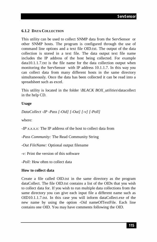
115
ServSensor
115
6.1.2 DATA COLLECTION
This utility can be used to collect SNMP data from the ServSensor orother SNMP hosts. The program is configured through the use ofcommand line options and a text file OID.txt. The output of the datacollection is stored in a text file. The data output text file nameincludes the IP address of the host being collected. For exampledata10.1.1.7.txt is the file name for the data collection output whenmonitoring the ServSensor with IP address 10.1.1.7. In this way youcan collect data from many different hosts in the same directorysimultaneously. Once the data has been collected it can be read into aspreadsheet such as excel.
This utility is located in the folder \BLACK BOX_utilities\datacollectin the help CD.
Usage
DataCollect -IP -Pass [-Oid] [-Out] [-v] [-Poll]
where:
-IP x.x.x.x: The IP address of the host to collect data from
-Pass Community: The Read Community String
-Out FileName: Optional output filename
-v: Print the version of this software
-Poll: How often to collect data
How to collect data
Create a file called OID.txt in the same directory as the programdataCollect. The file OID.txt contains a list of the OIDs that you wishto collect data for. If you wish to run multiple data collections from thesame directory you can give each input file a different name such asOID10.1.1.7.txt. In this case you will inform dataCollect.exe of thenew name by using the option -Oid nameOfTextFile. Each linecontains one OID. You may have comments following the OID.

116
ServSensor
116
A typical line in the OID.txt file could be:.1.3.6.1.4.1.3854.1.2.2.1.16.1.3.0 #this is the temperature 1
Start the program dataCollect. A typical command line could be:
dataCollect -IP 10.1.1.7 -Pass public -Poll 5
The program dataCollect will print to the screen after every pass of thedata collection. When you have collected enough data press CTRL-Cto stop the program from running.
The data output file called for example data10.1.1.7.txt should becopied to a new directory for analysis. This is suggested because thenext time dataCollect is run it will overwrite the output file.
Read the data output file into excel. Excel will load the text inputwizard. You should choose “Delimited” and press “Next”. You shouldthen choose comma and press Finish.
Example
datacollect -IP 192.168.0.30 -Pass public -Poll 5
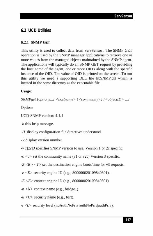
117
ServSensor
117
6.2 UCD Utilities
6.2.1 SNMP GET
This utility is used to collect data from ServSensor . The SNMP GEToperation is used by the SNMP manager applications to retrieve one ormore values from the managed objects maintained by the SNMP agent.The applications will typically do an SNMP GET request by providingthe host name of the agent, one or more OID's along with the specificinstance of the OID. The value of OID is printed on the screen. To runthis utility we need a supporting DLL file libSNMP.dll which islocated in the same directory as the executable file.
Usage:
SNMPget [options...] <hostname> {<community>} [<objectID> ...]
Options
UCD-SNMP version: 4.1.1
-h this help message.
-H display configuration file directives understood.
-V display version number.
-v 1|2c|3 specifies SNMP version to use. Version 1 or 2c specific.
-c <c> set the community name (v1 or v2c) Version 3 specific.
-Z <B> <T> set the destination engine boots/time for v3 requests.
-e <E> security engine ID (e.g., 800000020109840301).
-E <E> context engine ID (e.g., 800000020109840301).
-n <N> context name (e.g., bridge1).
-u <U> security name (e.g., bert).
-l <L> security level (noAuthNoPriv|authNoPriv|authPriv).

118
ServSensor
118
-a <A> authentication protocol (MD5|SHA).
-A <P> authentication protocol pass phrase.
-x <X> privacy protocol (DES).
-X <P> privacy protocol pass phrase
General communication options:
-p <P> use port P instead of the default port.
-T <LAYER> use LAYER for the network layer.(UDP or TCP).
-t <T> set the request timeout to T.
-r <R> set the number of retries to R.
Debugging:
-d dump input/output packets.
-D all | <TOKEN[,TOKEN,...]> turn on debugging output for thespecified TOK s.
General options:
-m all | <MIBS> use MIBS list instead of the default MIB list.
-M <MIBDIRS> use MIBDIRS as the location to look for MIBs.
-P <MIBOPTS> toggles various defaults controlling MIB parsing.
MIBOPTS values:
u: allow the usage of underlines in mib symbols.

119
ServSensor
119
c: disallow the usage of "--" to terminate.
Comments:
d: save the descriptions of the mib objects.
e: Disable mib errors of MIB symbols conflicts.
w: Enable mib warnings of MIB symbols conflicts.
W: Enable detailed warnings of MIB symbols.
Conflicts:
R: Replace MIB symbols from latest module
-O <OUTOPTS> Toggle various defaults controlling output display
OUTOPTS values:
n: Print OIDs numerically.
e: Print enums numerically.
b: Don’t break OID indexes down.
q: Quick print for easier parsing.
f: Print full OIDs on output.
s: Print only last symbolic element of OID.
S: Print MIB module-id plus last element.
-I <INOPTS> Toggle various defaults controlling input parsing:INOPTS values:

120
ServSensor
120
R: Do random access to OID labels.
b: Do best/regex matching to find a MIB node.
Example:
SNMPget -M c:\temp 10.1.1.7public.1.3.6.1.4.1.3854.1.2.2.1.16.1.10.0
Where:
c:\temp is the folder where the MIB files (ifmib.txt, ipmib.txt...etc.) arelocated
10.1.1.7 is the IP address of the ServSensor
public is the community name
.1.3.6.1.4.1.3854.1.2.2.1.16.1.10.0 is the OID
Example output:
z enterprises.3854.1.2.2.1.16.1.10.0 = 20

121
ServSensor
121
6.2.2 SNMP SET
This utility is used to set the SNMP Objects using the OID's forServSensor . The SNMP SET operation is used by the managementapplications and applets to modify the value of the managed object.Most of the managed objects will have a default value maintained bythe agent. But sometimes applications will be modifying the data forone or more MIB variables, in which case it will use the SNMP SEToperation. The new value set is printed on the screen. To run thisutility we need a supporting DLL file libSNMP.dll that is located inthe same directory as the executable file.
Usage:
SNMPset [options...] <hostname> {<community>} [<objectID><type> <value>...] ]
Options
UCD-SNMP version: 4.1.1 -h this help message.
-H display configuration file directives understood.
-V display version number.
-v 1|2c|3 specifies SNMP version to use. Version 1 or 2c specific.
-c <c> set the community name (v1 or v2c) Version 3 specific.
-Z <B> <T> set the destination engine boots/time for v3 requests.
-e <E> security engine ID (e.g., 800000020109840301).
-E <E> context engine ID (e.g., 800000020109840301).
-n <N> context name (e.g., bridge1).
-u <U> security name (e.g., bert).

122
ServSensor
122
-l <L> security level (noAuthNoPriv|authNoPriv|authPriv).
-a <A> authentication protocol (MD5|SHA).
-A <P> authentication protocol pass phrase.
-x <X> privacy protocol (DES).
-X <P> privacy protocol pass phrase
General communication options:
-p <P> use port P instead of the default port.
-T <LAYER> use LAYER for the network layer.(UDP or TCP).
-t <T> set the request timeout to T.
-r <R> set the number of retries to R.
Debugging:
-d dump input/output packets.
-D all | <TOKEN[,TOKEN,...]> turn on debugging output for thespecified TOK s.
General options:
-m all | <MIBS> use MIBS list instead of the default MIB list.
-M <MIBDIRS> use MIBDIRS as the location to look for MIBs.
-P <MIBOPTS> toggle various defaults controlling MIB parsing.
MIBOPTS values:

123
ServSensor
123
u: allow the usage of underlines in MIB symbols.
c: disallow the usage of "--" to terminate.
Comments:
d: save the descriptions of the MIB objects.
e: Disable MIB errors of MIB symbols conflicts.
w: Enable MIB warnings of MIB symbols conflicts.
W: Enable detailed warnings of MIB symbols.
Conflicts:
R: Replace MIB symbols from latest module
-O <OUTOPTS> Toggle various defaults controlling output display
OUTOPTS values:
n: Print OIDs numerically.
e: Print enums numerically.
b: Don’t break OID indexes down.
q: Quick print for easier parsing.
f: Print full OIDs on output.
s: Print only last symbolic element of OID.
S: Print MIB module-id plus last element.
-I <INOPTS> Toggle various defaults controlling input parsing:

124
ServSensor
124
INOPTS values:
R: Do random access to OID labels.
b: Do best/regex matching to find a MIB node.
type - one of i, u, t, a, o, s, x, d, n
i: INTEGER, u: unsigned INTEGER, t: TIMETICKS, a: IPADDRESS
o: OBJID, s: STRING, x: HEX STRING, d: DECIMAL STRING
U: unsigned int64, I: signed int64, F: float, D: double
Example:
SNMPset -M c:/temp 10.1.1.7 public1.3.6.1.4.1.3854.1.2.2.1.16.1.10.0 i 30
Where:
c:\temp is the folder where the MIB files (ifmib.txt, ipmib.txt...etc.)are located
10.1.1.7 is the IP address of the ServSensor
public is the community name
.1.3.6.1.4.1.3854.1.2.2.1.16.1.10.0 is the OID
i is the data type to be set 30 is the data to be set
Output
enterprises.3854.1.2.2.1.16.1.10.0 = 30

125
ServSensor
125
6.2.3 SNMP WALK
This utility fetches the SNMP objects using SNMP GET NEXT froman agent specified by the hostname. The value of the next OID isprinted on the screen. To run this utility we need a supporting DLLfile libSNMP.dll.
Usage:
SNMPget [options...] <hostname> {<community>} [<objectID> ...]
Options:
UCD-SNMP version: 4.1.1 -h this help message.
-H display configuration file directives understood.
-V display version number.
-v 1|2c|3 specifies SNMP version to use. Version 1 or 2c specific.
-c <c> set the community name (v1 or v2c) Version 3 specific.
-Z <B> <T> set the destination engine boots/time for v3 requests.
-e <E> security engine ID (e.g., 800000020109840301).
-E <E> context engine ID (e.g., 800000020109840301).
-n <N> context name (e.g., bridge1).
-u <U> security name (e.g., bert).
-l <L> security level (noAuthNoPriv|authNoPriv|authPriv).
-a <A> authentication protocol (MD5|SHA).
-A <P> authentication protocol pass phrase.

126
ServSensor
126
-x <X> privacy protocol (DES).
-X <P> privacy protocol pass phrase
General communication options
-p <P> use port P instead of the default port.
-T <LAYER> use LAYER for the network layer.(UDP or TCP).
-t <T> set the request timeout to T.
-r <R> set the number of retries to R.
Debugging:
-d dump input/output packets.
-D all | <TOKEN[,TOKEN,...]> turn on debugging output for thespecified TOK s.
General options:
-m all | <MIBS> use MIBS list instead of the default mib list.
-M <MIBDIRS> use MIBDIRS as the location to look for MIBs.
-P <MIBOPTS> toggles various defaults controlling MIB parsing.
MIBOPTS values:
u: allow the usage of underlines in MIB symbols.
c: disallow the usage of "--" to terminate.
Comments:

127
ServSensor
127
d: save the descriptions of the MIB objects.
e: Disable MIB errors of MIB symbols conflicts.
w: Enable MIB warnings of MIB symbols conflicts.
W: Enable detailed warnings of MIB symbols.
Conflicts:
R: Replace MIB symbols from latest module
-O <OUTOPTS> Toggle various defaults controlling output display
OUTOPTS values:
n: Print OIDs numerically.
e: Print enums numerically.
b: Don’t break OID indexes down.
q: Quick print for easier parsing.
f: Print full OIDs on output.
s: Print only last symbolic element of OID.
S: Print MIB module-id plus last element.
-I <INOPTS> Toggle various defaults controlling input parsing:
INOPTS values:
R: Do random access to OID labels.

128
ServSensor
128
b: Do best/regex matching to find a MIB node.
-C <APPOPTS> Toggle various application specific behaviour:
APPOPTS values:
p: Print the number of variables found.
i: Include the requested OID in the search range.
Example:
SNMPwalk -M c:/temp 10.1.1.7 public1.3.6.1.4.1.3854.1.2.2.1.16.1.10.1
Where:
c:\temp is the folder where the MIB files (ifmib.txt, ipmib.txt...etc.)are located
10.1.1.7 is the IP address of the ServSensor
public is the community name
.1.3.6.1.4.1.3854.1.2.2.1.16.1.10.0 is the OID
Output:
enterprises.3854.1.2.2.1.16.1.11.0 = 1

129
ServSensor
129
7. FAQ's
Q: Why am I unable to set the IP to the device using IPSet utilityprovided in the help CD?
A: Possibly:
a) The device is not hooked up properly with the LAN/network/Patchcable. The best method is to use a crossover cable from a computerdirectly to the ServSensor .
b) The PC used to configure is on a different subnet than the device.IPSet.exe will not work across routers.
Q: What is the default IP of the device?
A: The default IP assigned at the factory is: 192.168.0.100
Q: If the IPSet fails, is there any other method of assigning the IP?
A: Please do the following
a) find out the IP address of your network adapter by entering thecommand
ipconfig
b) Add the IP address of the ServSensor to the routing table byentering “route add 192.168.0.100 x.x.x.x” where x.x.x.x is the IPaddress of the network adapter
c) ping 192.168.0.100. If the ping works then open up your browserand access the web interface of the device by typing the IP192.168.0.100.

130
ServSensor
130
Q: Can I use the default IP of the device to access the webinterface and later assign the desired IP?
A: Yes, you can access the web interface by entering the IP192.168.0.100 in your browser.
Q: I’m able to ping the device IP, but I’m not getting the webinterface when I enter the IP in the browser?
A: Possible causes:
a) The proxy settings of the browser may be preventing the access tothe device. Please disable the proxy settings to access the webinterface.
b) You have updated the firmware, but you have not updated the htmlcode update. Html code updates has to be done, after the firmwareupdate is done.
Q: Where can I find the MAC address of the device?
A: The MAC address of the device can be found on the bottom coverof the device, and also on the web interface under System page.
Q: After some days of use, I have changed the IP of the device. Butit changes to the old IP after a few hours. How can I prevent this?
A:
a) What is happening is that after the IP address has been changed bythe user, it is being changed back by a network management program.One way that you can change the IP address is to statically set the ARPcache to associate the MAC address with the IP address and then pingit. Therefore someone or some automated network management

131
ServSensor
131
program can later come by and ping the old IP address and therebyreset the IP address back to the previous value.
b) The way to prevent this from happening is to go to the send anSNMP command to the device to disallow IP changes to be made. Wedo not have this command on the user interface because once set theIPSet program can no longer be used to change the IP address until anSNMP command is sent to the box to undo this setting and allow theIP address to once again be changed.
The command to disable the IP change is:
SNMPset <IP> <community> .1.3.6.1.4.1.3854.1.2.2.1.62.0 i X
Where:
IP is the IP address of the device
community default is "public"
X can take 2 values: 1 (enable IP change), 2 (disable IP change).
NOTEIf the user forgets the IP address while this setting is in effect the device will beunusable.
Q: Where can I find the MIB file for the device?
A: The MIB file for the device can be found in the help CD, under thedirectory: \utilities\mib\
Q: I cannot set the device to send mails?
A: Possible causes may be:
a) The SMTP server is entered is wrong.

132
ServSensor
132
b) Send mail option is not enabled in the Mail settings page.
c) The timeout period entered is too low.
d) The gateway IP is not entered in the network page
e) The mail from address is not set
f) The mail server is not responding
g) The mail from address is not validated in the mail server
h) The mail server settings prohibit it from accepting connections formthe device IP
i) The firewall in the network is preventing the SMTP traffic.
Q: I cannot log in to the device.
A: Possible causes may be:
a) The password entered is wrong.
b) The password has been changed by another user.
Q: I’m not able to change the settings in the device.
A: You have logged into the device as a user. Only an administratorcan make changes to the settings.
Q: How can I recover a lost password?
A: You need to contact BLACK BOX support.
Q: The device is not able to send Traps

133
ServSensor
133
A: Possible causes may be:
a) The destination TRAP IP is not set in the TRAP settings page.
b) The community entered is wrong.
c) The firewall is blocking the TRAP traffic.
d) The send Trap option is Off.
Q: I have HP OpenView, but I’m not able to receive the Traps.
A: Possible causes may be:
a) For changing the Traps to HP OpenView style, you need to send anSNMP command to the device given below:
SNMPset <IP> <community> .1.3.6.1.4.1.3854.1.2.2.1.60.0 i X
Where:
IP is the IP address of the ServSensor
community default is "public"
X can take 3 values: 1 (WhatsUP gold style), 2 (HP OpenView Style),3 (both Style). By default, the X value set is 1.
Q: I have assigned the gateway IP, and when I say set, it revertsback to the default IP?
A: This happens when the device is not able to find the IP entered.When the IP is entered, the device searches for the IP, if it’s found, itwill accept the IP entered, else it will revert back to the default IP.
Q: Is the temperature sensor built inside the ServSensor ?

134
ServSensor
134
A: No. We tried to do that when we first designed the ServSensor . Itis much cheaper to have an integrated temperature sensor. That is thepurpose of the grill on the top of the box. What we found is that thereis no way to stop the heat from the ServSensor from affecting thetemperature sensor; this ranges between 2 to 4 degrees Celsius. Whatwould have been necessary had we proceeded with that design wouldhave been to "tune" out the offset by applying a fudge factor. Theproblem is that this fudge factor would have had to change dependingon the temperature and the operating conditions. So if we add in fudgefactor for normal room temperatures it would have to change whenthere was a problem with the air conditioning and the ambienttemperature was higher. Because of all these reasons, we came up withthe external sensors, so that the measurements done by that sensor areaccurate and there is no need for calibration.

135
ServSensor
135

136
ServSensor
136
© Copyright 2004. Black Box Corporation. All rights reserved.
BLACK BOX Network Services