Embed Size (px)
Citation preview
SeriesAdvanced Double Column Vertical Machining Center
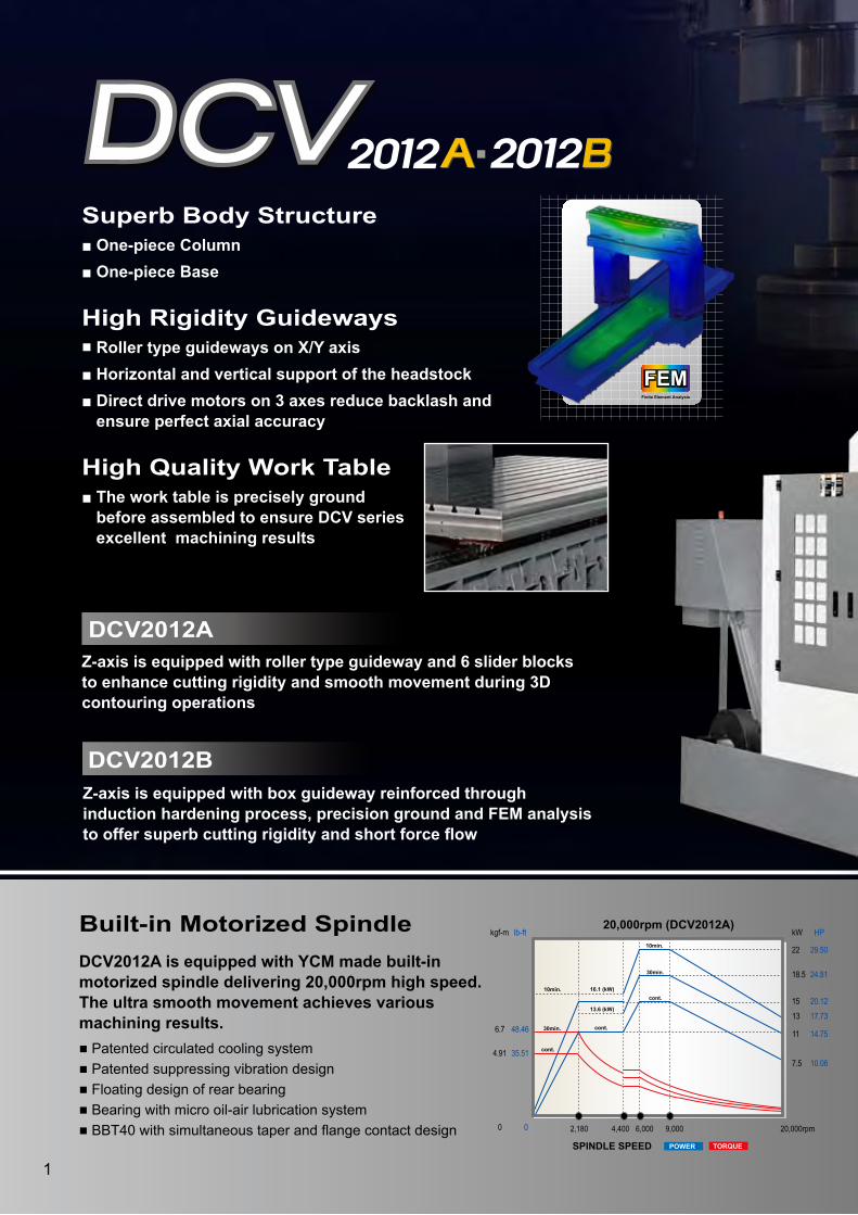
ACCURACYSuperb Body Structure■ One-piece Column■ One-piece Base
High Rigidity Guideways■ Roller type guideways on X/Y axis■ Horizontal and vertical support of the headstock■ Direct drive motors on 3 axes reduce backlash and ensure perfect axial accuracy
High Quality Work Table■ The work table is precisely ground before assembled to ensure DCV series excellent machining results
Z-axis is equipped with box guideway reinforced through induction hardening process, precision ground and FEM analysis to offer superb cutting rigidity and short force flow
DCV2012A
DCV2012B
Z-axis is equipped with roller type guideway and 6 slider blocks to enhance cutting rigidity and smooth movement during 3D contouring operations
kWkgf-m
4,500rpm
88.87
74.73
60.59
29.62
19.0416.0112.989.52
22
18.5
15
11
964723241 1,125 2,893 3,857
a
bc e
d fg
cont.
15min.
30min.
cont.
15min.
30min.
cont.
15 min.
30 min.
15 min.30 min.
cont.
4,500rpm (50#)
6,000rpm (50#)kWkgf-m
6,000rpm
66.65
56.05
45.44
22.22
14.2812.019.747.14
22
18.5
15
11
1,286964321 1,500 3,857 5,143
c ed f
g
cont.
15min.
30min.
cont.
15min.
30min.
cont.
15min.
30min.
15min.30min.cont.b
a
kgf-m
10,000rpm
36.04
29.22
7.319.01
10.71
2.141.80
500 2,0001,600
30min.
30min.
cont.
cont.
30min.
30min.
cont.
cont.
cont.
10,000rpm (50#)
20,000rpm (DCV2012A)
0 20,000rpm2,180 4,400 6,000 9,000
16.1 (kW)
13.6 (kW)
cont.
cont.
cont.
30min.
10min.
10min.
30min.
kW
7.5
18.5
13
11
HP
10.06
24.81
15 20.12
22 29.50
17.73
14.75
kgf-m
4.91
6.7
0
lb-ft
35.51
48.46
POWER TORQUE
14.01 101.3411.36 82.175.55 40.14
3.50 25.322.84 20.542.43 17.581.79 12.95
kgf-m Ib-ft kgf-m Ib-ft
kgf-m Ib-ft kgf-m Ib-ft 18.68 135.12
15.15 109.587.41 53.60
4.67 33.783.79 27.413.25 23.512.38 17.21
Ib-ft
642.81
540.53
438.26
214.25
137.72115.8093.8968.86
HP
29.50
24.81
20.12
14.75
Ib-ft
482.09
405.42
328.67
160.72
103.2986.8770.4551.64
HP
29.50
24.81
20.12
14.75
SPINDLE SPEED TORQUE High SpeedLow Speed
POWER High SpeedLow Speed
SPINDLE SPEED TORQUE High SpeedLow Speed
POWER High SpeedLow Speed
SPINDLE SPEED TORQUE High SpeedLow Speed
POWER High SpeedLow Speed
SPINDLE SPEED
Ib-ft
260.68
211.35
52.8765.1777.47
15.4813.02
kW HP
22 29.50
18.5 24.81
15 20.12
5 6.71
1
FEMFEMFinite Element Analysis
FEMFEMFinite Element Analysis
DCV2012A is equipped with YCM made built-in motorized spindle delivering 20,000rpm high speed. The ultra smooth movement achieves various machining results. ■ Patented circulated cooling system■ Patented suppressing vibration design■ Floating design of rear bearing ■ Bearing with micro oil-air lubrication system■ BBT40 with simultaneous taper and flange contact design
Built-in Motorized Spindle

with MXP-200i Control by FANUC
高性能永進發那科 MXP-200i 數位式控制系統
Advanced Double Column Vertical Machining Center
Advanced Double Column Vertical Machining Center
■ Hardened and Ground Box Guideway on Z-axis (DCV2012B)
■ Roller Type Guideway on Z-axis (DCV2012A)
■ Horizontal and Vertical Support of the Headstock
2
Y 1600mm X 3060mm
Z 762mm
FEMFEMFinite Element Analysis
FEMFEMFinite Element Analysis
3
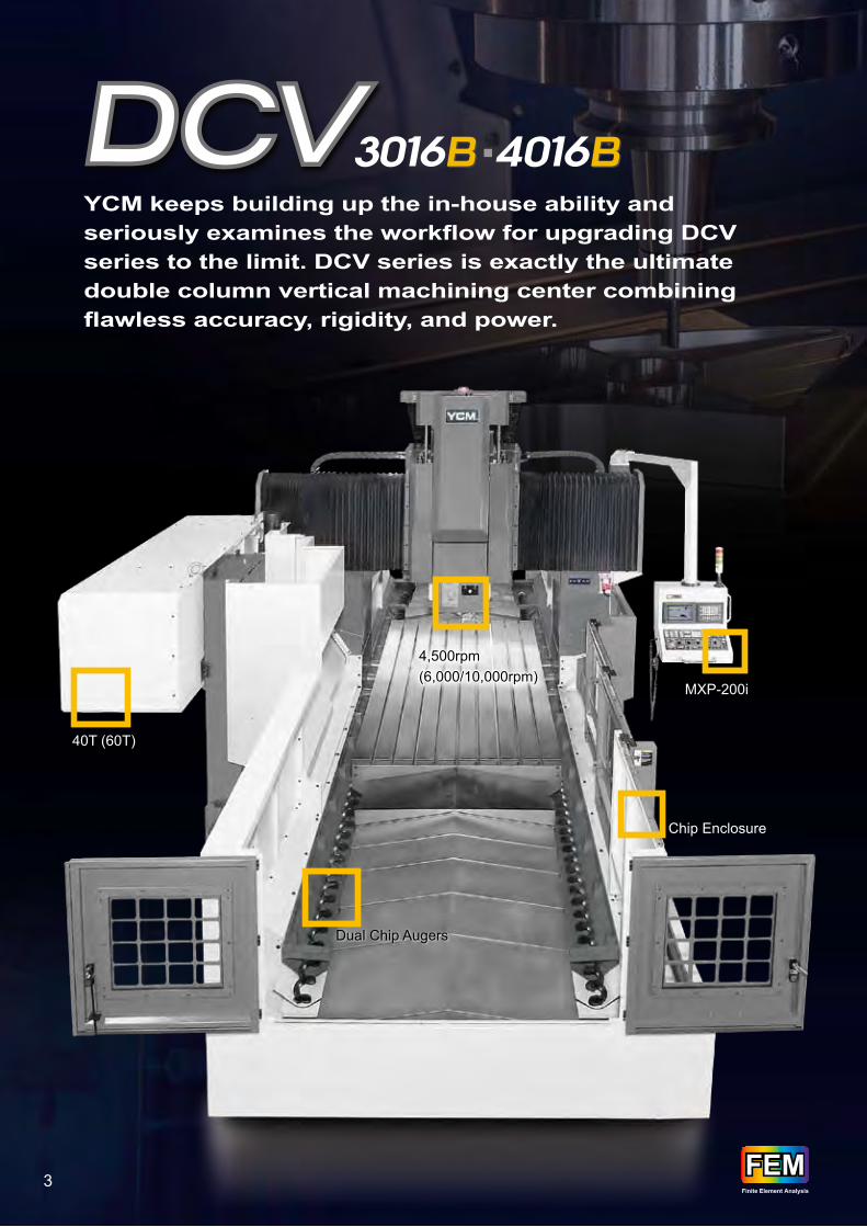
Chip Enclosure
4,500rpm (6,000/10,000rpm)4,500rpm (6,000/10,000rpm)
Dual Chip Augers
40T (60T)
MXP-200i
FEMFEMFinite Element Analysis
FEMFEMFinite Element Analysis
YCM keeps building up the in-house ability and seriously examines the workflow for upgrading DCV series to the limit. DCV series is exactly the ultimate double column vertical machining center combining flawless accuracy, rigidity, and power.

NSV系列機種之三軸快速 壓送最高可達48m/min,軸向加速度最高1g*運動效能。
Superb Body Structure■ One-piece Column■ One-piece Base■ Rigid proportion of the headstock
High Rigidity Guideways■ X-axis is directly driven by gearbox offering smooth axial response and high torque■ Roller type guideways on X/Y axis■ Y-axis is supported by 3 roller type guideways and 6 slider blocks to offer ultimate cutting rigidity■ Horizontal and vertical support of the headstock■ Hardened and ground box guideway on Z-axis enlarges the contact interface for high machining stability
Y 1600mm X 3060mm
Z 762mm
■ Hardened and Ground Box Guideway on Z-axis
■ Rigid Proportion of the Headstock
4
One-piece Column
Roller Type Guideway
One-piece Base
Reinforced Body Structure
Supported by 3 Roller Type Guideways
Force
Force Force
Double Gibs DesignSaddle
RAM
1.8L
1L
1.1L
2.1L
Z-axis travel
762mm 30" (std.)
Z-axis travel
1,016mm 40" (opt.)
■ Horizontal and Vertical Support of the Headstock

ACCURACY
ACCURACY
DCV series flawless accuracy, rigidity, and power are suitable for diverse requirements from automative, die & mold, energy and aerospace industries.
YCM Self-developed STC PLUS Spindle Thermal Compensation Achieves High Accuracy (opt.)
1 2
5
Full Chip Enclosure (opt.)
Max. Tool Magazine Capacity: 120T (opt.)
Front or Rear Chip Conveyor

Force
Reaction
L1
L1=L2
Force
L2L2
L1<L2
L1
Reaction
Competitors YCM
High Rigidity Internal Ribs Structure Design
Superb Body Structure■ Turcite-B design on Z-axis strengthens rigidity and damping capacity reducing overhang and vibration problems■ Extra wide column base with boots design prevents the headstock from leaning forward■ Internal ribs structure design through FEM analysis delivers high rigidity and stability
■ 40T■ 60/120T (opt.)■ Arm Type ATC System; Prevents Tools from Dropping; Tool to Tool: 3 Sec.
1
2
3
3
6
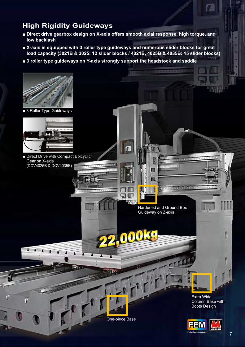
■ 3 Roller Type Guideways
■ Direct Drive with Compact Epicyclic Gear on X-axis (DCV4025B & DCV4035B)
High Rigidity Guideways■ Direct drive gearbox design on X-axis offers smooth axial response, high torque, and low backlash■ X-axis is equipped with 3 roller type guideways and numerous slider blocks for great load capacity (3021B & 3025: 12 slider blocks / 4021B, 4025B & 4035B: 15 slider blocks) ■ 3 roller type guideways on Y-axis strongly support the headstock and saddle
6 7
Y 1600mm X 3060mm
Z 762mm
FEMFEMFinite Element Analysis
FEMFEMFinite Element Analysis
Extra Wide Column Base with Boots Design
One-piece Base
Hardened and Ground Box Guideway on Z-axis

300°/
Spindle Speed: 10,000rpmSpindle Power: 46kW / 61.7HPMax. Torque: 242Nm
Advanced Double Column 5-axis Vertical Machining Center
Equipped with ROBO I, YCM-made high performance universal milling head, DCV4030B-5AX is specialized for applications demanding complex machining such as aerospace, automotive, medical and energy industries.
B/C axes Max. Rotary Speed
300°/sec.
8
Extra Wide Column Base with Boots Design
Roller Type Guideways
One-piece Base

300°/
5AX ROBO I Achieves Perfect 3D Contouring Operations■ High rigidity symmetrical fork type structure design minimizes heat deformation during heavy cutting applications. ■ The main structure is made of superior nodular graphite cast iron.■ High dynamic universal milling head, built-in motorized spindle with HSK-A100 taper offers max. spindle speed 10,000rpm.■ Coolant through spindle system: 20 bar.■ Superb spindle coolant system.
High Rigidity B/C Axis■ Direct drive motor design delivers high torque, low backlash and perfect clamping capacity.■ HEIDENHAIN encoder enhances the cutting accuracy.■ Disc type hydraulic clamping device.■ Rotary joint design prevents the damage on the hydraulic tubes caused during rotation.■ Double direction roller bearings for perfect cutting rigidity.■ Superb spindle coolant system.
SPINDLE SPEED (rpm) TORQUE High SpeedLow Speed
POWER High SpeedLow Speed
rpm
kW HPIb-ftkgf-m
24.77 179.16
21.41 154.86 41.0 54.98
5.10 24.14
46.0 61.69
4.69 24.14
40.0 53.64
S6-60%
S6
cont.cont.
10,0001,820 4,960 8,000
10,000rpmSTANDARD
■ ±110° Swivel Angle (B-axis)■ ±360° Rotary Angle (C-axis)
JIS B 6338ISO 10791-4
VDI/DGQ3441 is equivalent to A of ISO10791-4, and PS is equivalent to R. All values shown above are measured for the machine in good air-conditioned environments.
ACCURACYStandard
Positioning AAxial Travel
Repeatability R
Full Length
Tolerances
JIS B 6338ISO 10791-4
0.025mm 0.00098”0.020mm 0.00079”
VDI/DGQ3441 is equivalent to A of ISO10791-4, and PS is equivalent to R. All values shown above are measured for the machine in good air-conditioned environments.
ACCURACYStandard
Positioning AAxial Travel
Repeatability R
Full Length
Tolerances
0.010/300mm 0.00039”/11.81”±0.003mm ±0.00012”
JIS B 6338ISO 10791-4
0.010mm 0.00039”VDI/DGQ3441 is equivalent to A of ISO10791-4, and PS is equivalent to R. All values shown above are measured for the machine in good air-conditioned environments.
ACCURACYStandard
Positioning AAxial Travel
Repeatability R
Full Length -
Tolerances
±0.010mm ±0.00039”±0.003mm ±0.00012”
±0.010mm ±0.00039”±0.003mm ±0.00012”
0.025mm 0.00098”0.020mm 0.00079”
±0.010mm ±0.00039”±0.003mm ±0.00012”
JIS B 6338ISO 10791-4
0.020mm 0.00079”0.015mm 0.00059”
0.015mm 0.00059” 0.010/300mm 0.00039”/11.81”±0.003mm ±0.00012”
JIS B 6338ISO 10791-4
0.015mm 0.00059”VDI/DGQ3441 is equivalent to A of ISO10791-4, and PS is equivalent to R. All values shown above are measured for the machine in good air-conditioned environments.
ACCURACYStandard
Positioning AAxial Travel
Repeatability R
Full Length -
Tolerances
0.020mm 0.00079”
0.010/300mm 0.00039”/11.81”±0.003mm ±0.00012”
JIS B 6338ISO 10791-4
0.020mm 0.00079”VDI/DGQ3441 is equivalent to A of ISO10791-4, and PS is equivalent to R. All values shown above are measured for the machine in good air-conditioned environments.
ACCURACYStandard
Positioning AAxial Travel
Repeatability R
Full Length -
Tolerances
0.025mm 0.00098” 0.010/300mm 0.00039”/11.81”±0.003mm ±0.00012”
JIS B 6338ISO 10791-4
0.020mm 0.00079”VDI/DGQ3441 is equivalent to A of ISO10791-4, and PS is equivalent to R. All values shown above are measured for the machine in good air-conditioned environments.
ACCURACYStandard
Positioning AAxial Travel
Repeatability R
Full Length -
Tolerances
0.025mm 0.00098”
VDI/DGQ3441 is equivalent to A of ISO10791-4, and PS is equivalent to R. All values shown above are measured for the machine in good air-conditioned environments.
ACCURACYStandard
Positioning AAxial Travel
Repeatability R
Full Length
Tolerances
ISO 10791-4
20”15”
VDI/DGQ3441 is equivalent to A of ISO10791-4, and PS is equivalent to R. All values shown above are measured for the machine in good air-conditioned environments.
ACCURACYStandard
Positioning AAxial Travel
Repeatability R
Full Length
Tolerances
4030B-5AX (B/C axes)
9
110° 110°

Superb Body Structure & X/Y/Z Guideways Designs■ Massive MEEHANITE® casting through FEM analysis offers exceptional damping capacity. ■ Direct drive gearbox design on X/Y/Z axis offers smooth axial response, high torque, and low backlash.■ Extra wide column base with boots design.■ Equipped with roller type guideways and numerous slider blocks for great load capacity and cutting rigidity.
HEIDENHAIN Control■ 5-axis simultaneous control by HEIDENHAIN iTNC530 HSCI increases efficiency, tool life, and cutting accuracy.■ Tool center point management [TCPM], dynamic collision monitoring [DCM] and DFX converter (opt.).■ Program memory hard disk with 21GB.■ smarT.NC.
■ HEIDENHAIN iTNC530 HSCI
9 10
Dual Chip Augers
Max. Tool Magazine Capacity: 120T (opt.)
Chip Enclosure

DCV series is assembled through serious quality control process to ensure high dynamic accuracy during contouring operations.
POSITIONING ACCURACY 614mm x 454mm
-1.4µm/613.9986mm
+4.8µm/454.0048mm
-4.4µm/613.9956mm
-2.8µm/453.9972mm
The test data in this brochure is provided as an example under specific guidelines. Results may be different due to variation in machine settings or environmental conditions during machining and measuring.
ACCURACY
ABCD
A
B
C
D
JIS B 6338ISO 10791-4
VDI/DGQ3441 is equivalent to A of ISO10791-4, and PS is equivalent to R. All values shown above are measured for the machine in good air-conditioned environments.
ACCURACYStandard
Positioning AAxial Travel
Repeatability R
Full Length
Tolerances
JIS B 6338ISO 10791-4
0.025mm 0.00098”0.020mm 0.00079”
VDI/DGQ3441 is equivalent to A of ISO10791-4, and PS is equivalent to R. All values shown above are measured for the machine in good air-conditioned environments.
ACCURACYStandard
Positioning AAxial Travel
Repeatability R
Full Length
Tolerances
0.010/300mm 0.00039”/11.81”±0.003mm ±0.00012”
JIS B 6338ISO 10791-4
0.010mm 0.00039”VDI/DGQ3441 is equivalent to A of ISO10791-4, and PS is equivalent to R. All values shown above are measured for the machine in good air-conditioned environments.
ACCURACYStandard
Positioning AAxial Travel
Repeatability R
Full Length -
Tolerances
±0.010mm ±0.00039”±0.003mm ±0.00012”
±0.010mm ±0.00039”±0.003mm ±0.00012”
0.025mm 0.00098”0.020mm 0.00079”
±0.010mm ±0.00039”±0.003mm ±0.00012”
JIS B 6338ISO 10791-4
0.020mm 0.00079”0.015mm 0.00059”
0.015mm 0.00059” 0.010/300mm 0.00039”/11.81”±0.003mm ±0.00012”
JIS B 6338ISO 10791-4
0.015mm 0.00059”VDI/DGQ3441 is equivalent to A of ISO10791-4, and PS is equivalent to R. All values shown above are measured for the machine in good air-conditioned environments.
ACCURACYStandard
Positioning AAxial Travel
Repeatability R
Full Length -
Tolerances
0.020mm 0.00079”
0.010/300mm 0.00039”/11.81”±0.003mm ±0.00012”
JIS B 6338ISO 10791-4
0.020mm 0.00079”VDI/DGQ3441 is equivalent to A of ISO10791-4, and PS is equivalent to R. All values shown above are measured for the machine in good air-conditioned environments.
ACCURACYStandard
Positioning AAxial Travel
Repeatability R
Full Length -
Tolerances
0.025mm 0.00098” 0.010/300mm 0.00039”/11.81”±0.003mm ±0.00012”
JIS B 6338ISO 10791-4
0.020mm 0.00079”VDI/DGQ3441 is equivalent to A of ISO10791-4, and PS is equivalent to R. All values shown above are measured for the machine in good air-conditioned environments.
ACCURACYStandard
Positioning AAxial Travel
Repeatability R
Full Length -
Tolerances
0.025mm 0.00098”
VDI/DGQ3441 is equivalent to A of ISO10791-4, and PS is equivalent to R. All values shown above are measured for the machine in good air-conditioned environments.
ACCURACYStandard
Positioning AAxial Travel
Repeatability R
Full Length
Tolerances
ISO 10791-4
20”15”
VDI/DGQ3441 is equivalent to A of ISO10791-4, and PS is equivalent to R. All values shown above are measured for the machine in good air-conditioned environments.
ACCURACYStandard
Positioning AAxial Travel
Repeatability R
Full Length
Tolerances
3016B/3021B/3025B
4016B/4021B/4025B 4035B/4030B-5AX
2012A/2012B
11
Test Model: DCV3016B

880mm34”
880mm34”
1,52
8mm
60”
1,52
8mm
60”
User-friendly Design
478mm18”
478mm18”
Note: The above data is for reference only. All the cutting tests are designed to demonstrate maximum machining capabilities without preserving tool life.
SteelS45C
1,000cc/min.
Material Removal Rate
ToolSpindle Speed
FeedrateWidth of CutDepth of Cut
Spindle Load
FACE MILLING
M48TAP
SteelS45CTAPPING
ToolSpindle Speed
FeedrateSpindle Load
0#TAP
AluminumTAPPING
ToolSpindle Speed
FeedrateTooth Pitch
ø60mm
Cutter Diameter
ToolSpindle Speed
FeedrateSpindle Load
SteelS45CDRILLING
SteelS45C
450cc/min.
Material Removal Rate
ToolSpindle Speed
FeedrateWidth of CutDepth of Cut
Spindle Load
FACE MILLING
ø160mm x 10T375rpm1,600mm/min.125mm5mm144%
M48 x 5P45rpm225mm/min.72%
ø160mm x 10T300rpm400mm/min.125mm9mm75%
ø60mm133rpm48mm/min.25%
0#80UNF1,200rpm381mm/min.0.3175mm
BT50/4,500rpmCutting Tests
Model: DCV3016B
12

kWkgf-m
4,500rpm
88.87
74.73
60.59
29.62
19.0416.0112.989.52
22
18.5
15
11
964723241 1,125 2,893 3,857
a
bc e
d fg
cont.
15min.
30min.
cont.
15min.
30min.
cont.
15 min.
30 min.
15 min.30 min.
cont.
4,500rpm (50#)
6,000rpm (50#)kWkgf-m
6,000rpm
66.65
56.05
45.44
22.22
14.2812.019.747.14
22
18.5
15
11
1,286964321 1,500 3,857 5,143
c ed f
g
cont.
15min.
30min.
cont.
15min.
30min.
cont.
15min.
30min.
15min.30min.cont.b
a
kgf-m
10,000rpm
36.04
29.22
7.319.01
10.71
2.141.80
500 2,0001,600
30min.
30min.
cont.
cont.
30min.
30min.
cont.
cont.
cont.
10,000rpm (50#)
20,000rpm (DCV2012A)
0 20,000rpm2,180 4,400 6,000 9,000
16.1 (kW)
13.6 (kW)
cont.
cont.
cont.
30min.
10min.
10min.
30min.
kW
7.5
18.5
13
11
HP
10.06
24.81
15 20.12
22 29.50
17.73
14.75
kgf-m
4.91
6.7
0
lb-ft
35.51
48.46
POWER TORQUE
14.01 101.3411.36 82.175.55 40.14
3.50 25.322.84 20.542.43 17.581.79 12.95
kgf-m Ib-ft kgf-m Ib-ft
kgf-m Ib-ft kgf-m Ib-ft 18.68 135.12
15.15 109.587.41 53.60
4.67 33.783.79 27.413.25 23.512.38 17.21
Ib-ft
642.81
540.53
438.26
214.25
137.72115.8093.8968.86
HP
29.50
24.81
20.12
14.75
Ib-ft
482.09
405.42
328.67
160.72
103.2986.8770.4551.64
HP
29.50
24.81
20.12
14.75
SPINDLE SPEED TORQUE High SpeedLow Speed
POWER High SpeedLow Speed
SPINDLE SPEED TORQUE High SpeedLow Speed
POWER High SpeedLow Speed
SPINDLE SPEED TORQUE High SpeedLow Speed
POWER High SpeedLow Speed
SPINDLE SPEED
Ib-ft
260.68
211.35
52.8765.1777.47
15.4813.02
kW HP
22 29.50
18.5 24.81
15 20.12
5 6.71
6,000rpm SpindleWith Hi-lo Gear Transmission
6,000rpm spindle is available for diverse requirements. The design of 2-step gear transmission is complimented with a powerful AC digital spindle motor and ceramic roller type bearings. The 6,000rpm spindle is capable of reaching up to 22kW and 66.65kgf-m torque output at 321rpm. DCV series can easily achieve 1,000 cc/min. chip removal rate and promote productivity.
10,000rpm SpindleIsolated Direct Drive Design
10,000rpm IDD spindle is optional to be equipped with DCV series. Driven by 22kW dual step AC digital spindle motor, the spindle is able to reach max. 36.04kgf-m torque output at 500rpm. Unique IDD design offers low spindle vibration and optimal heat isolation that results in excellent accuracy after long-term operation.
89kgf-mDCV Max. Torque at Low Speed
Spin
dle
Mot
or T
orqu
e C
hart
Spin
dle
Mot
or T
orqu
e C
hart
Spin
dle
Mot
or T
orqu
e C
hart
644 lb-ft
Torque
4,500rpm Spindle
13
4,500rpm SpindleWith Hi-lo Gear Transmission
4,500rpm spindle speed is standard with 2-step gear transmission. The spindle incorporates roller type spindle bearings for extremely high cutting rigidity. The 2-step gear transmission provides 88.87kgf-m torque output at 241rpm ideal for machining hard material.
■
■
■

85 3.35”
45 1.77” 40 1.57”
8 0.31”5
0.2”
5 0.20”5
0.20”
24 0.94”
3 0.12”
ø17
ø0.6
7”
45°
ø20
ø0.
79”
8 0.31”
10 0.39”
60°
ø23
ø0.9
1”
351.38”
M24
x 3
P
85 3.35”
45 1.77” 40 1.57”
8 0.31”
5 0.20”
5 0.20”
24 0.94”
3 0.12”
ø25
0.98
”
ø17
ø0.6
7”
45°
ø20
ø0.
79”
8 0.31” 10 0.39”
60°
ø23
ø0.9
1”
351.38”
M24
x 3
P
ø38
ø1.5
”ø3
8 ø1
.5”
BBT40
CAT40 CAT50
DIN69871 (#40)
BT50
ø85
ø3.3
5”
ø100
ø3.
94”
7 0.28”
15 0.59”
23.2 0.91”
60°
35 1.38”
38 1.5”
3 0.12”
25.7
1.01
”
ø69.
85 2
.75”
M24 x 3P
Taper 7/24
101.8 4.01”
139.8 5.5”
ø91.
29 ø
3.6”
ø98.
43 ø
3.88
”
3.84 0.15”
7 0.28”
12 0.47”
60°15.88 0.63”3.18 0.13”
101.6 4”
120.65 4.75”
ø25
ø0.9
8”60°
25.4-8UNC
25.4-8UNC
85 3.35”45 1.77” 40 1.57”
50.2”
50.2”
35.21.38”
10 0.39”
45°
60°
ø17
ø0.6
7”
ø20
ø0.79
” ø23
ø0.9
1”
3 0.12”24 0.94”5 0.2”8 0.31”
DIN69871 (#50)
6.5 0.26”
120.85 4.76”
101.75 4.01”
15.9 0.63”3.2 0.13”
19.1 0.75”
60°
M24 x 3P
ø40.
1ø1
.57”
ø40.
1ø1
.57”
60°
ø25
ø0.9
8”
ø69.
85ø2
.76”
ø97.
5 3.
84”
ø91.
25 3
.59”
3.75 0.15”
11.1 0.44”
RK31118
MAS-P50T-1
PY030364
65.4 2.57” 16.6 0.65”
Taper 7/24
M16
x 2
Pø10 ø0.39”
ø44.
45 ø
1.75
”
250.98”
ø53
ø2.0
9”
ø75.
679
ø2.9
8”ø6
3 ø2
.48”
Ball Diameter
ø44.
45 ø
1.75
”
68.252.69”
11.10.44”
ø45
ø1.
77”
ø56.
36 ø
2.22
”
ø63.
5 ø
2.50
”
ø72.
32 ø
2.85
”
3.180.13”
19.050.75”
35 1.38”
5/8"
-11U
NC
Taper 7/24
Min.
Ball Diameter
Max
.
ø7ø0.28”
ø44.
45 ø
1.75
”
35 1.38”
ø7ø0.28”
ø100 ø3.94”
68.4 2.69” 11.10.44”
ø50
ø1.
97”
ø56.
25 ø
2.21
”
ø63.
55 ø
2.5”
ø72.
3 ø
2.85
”
3.20.13”
19.10.75”
Taper 7/24
M16
x 2
P
Min.
Ball Diameter
Max
.
ø25
0.98
”
ø25
0.98
”
80.31”
ø38
ø1.5
”
HSK-A100Taper 1/10
30.13”
40.16”
ø17
ø0.6
7”
MAS-P40T-154 2.12”
ø19
ø0.74
”
ø14
ø0.5
5”
29 1.14” 6.1 0.24”
M16
x 2
P
ø23
ø0
.9”
ø23 ø0.9”
40.16”
ø17
ø0.6
7”
ø19
ø0.74
”
6.10.24”
RK31114
51 2.0”
20 0.79”
261.02”
M16
x 2
P
ø23
ø0
.9”
ø14
ø0.5
5”
ø19
ø0.74
”
20 0.79”
拉刀螺栓 (特殊)
7 0.28”
26.15 1.03”
50 1.97”
6.5 0.26”
5/8”
-11U
NC
Unit: mm inch TOOL SHANK
14
646
800 800
442
4,01
0
4,65
6
1,308 1,310
5,450 600600
645
FANUC C30/1500iB(with brake)
622
646
800 800
442
4,01
0
4,65
6
1,308 1,310
5,450 600600
645
FANUC C30/1500iB(with brake)
622
Unit: mm inch DIMENSIONS
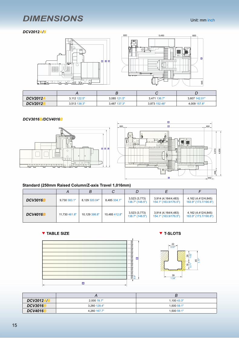
A B C DDCV2012A 3,112 122.5" 3,085 121.5" 3,471 136.7" 3,607 142.01"
DCV2012B 3,513 138.3" 3,487 137.3" 3,873 152.48" 4,009 157.8"
A B C D E F
DCV3016B 9,730 383.1" 8,129 320.04" 8,485 334.1" 3,523 (3,773)138.7" (148.5")
3,914 (4,164/4,483)154.1" (163.9/176.5")
4,162 (4,412/4,845)163.9" (173.7/190.8")
DCV4016B 11,730 461.8" 10,129 398.8" 10,485 412.8" 3,523 (3,773)138.7" (148.5")
3,914 (4,164/4,483)154.1" (163.9/176.5")
4,162 (4,412/4,845)163.9" (173.7/190.8")
A BDCV2012A/B 2,000 78.7" 1,100 43.3"
DCV3016B 3,260 128.4" 1,500 59.1"
DCV4016B 4,260 167.7" 1,500 59.1"
DCV2012A/B
DCV3016B/DCV4016B
150
150
150
150
150
150
150
150
150
150
1826
22
45
39
0.87”
1.02
”
1.77
”
0.71
”
1.54”5.9”
7.9”
200
2002
0020
0200
2002
0020
0200
200
TABLE SIZE T-SLOTS
TABLE SIZE T-SLOTS
20
28
28
49
46
1.10”
1.81”
1.10
”0.
79” 1.
93”
7.9”
200
2002
0020
0200
2002
0020
0200
200
TABLE SIZE T-SLOTS
20
28
28
49
46
1.10”
1.81”
4,100 161.4"
2,40
0 94
.5"
1.10
”0.
79” 1.
93”
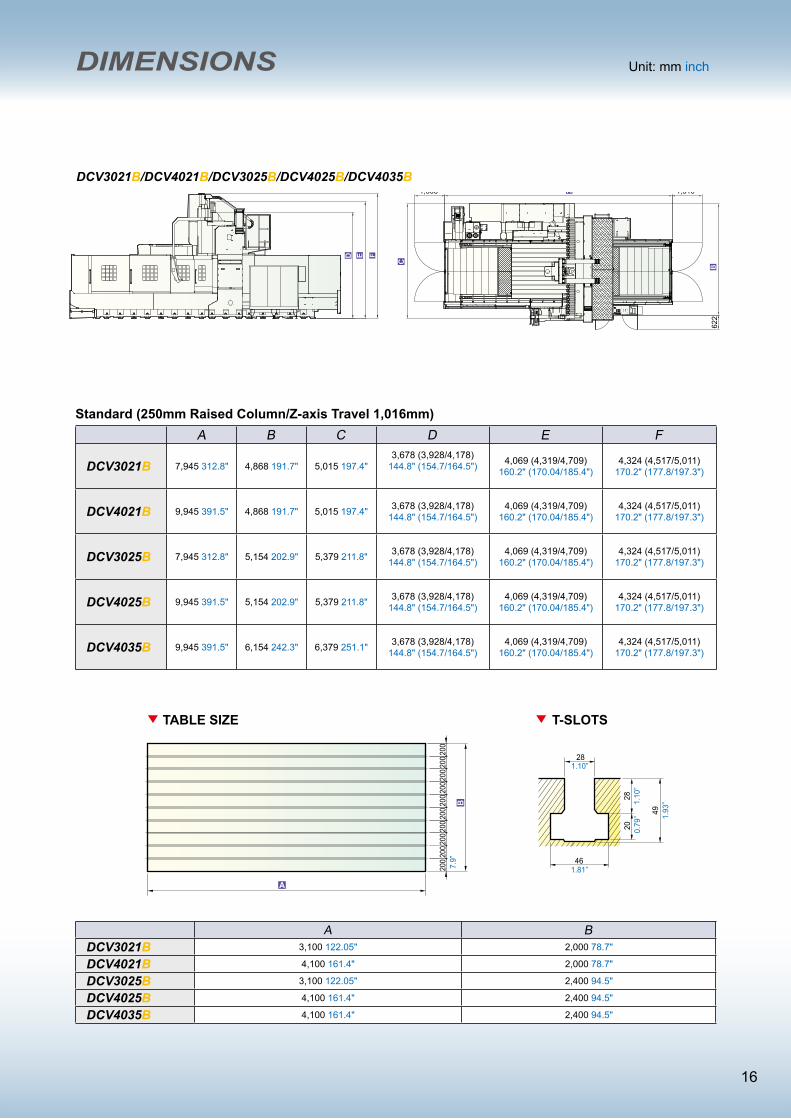
Standard (250mm Raised Column/Z-axis Travel 1,016mm)
15
646
800 800
442
4,01
0
4,65
6
1,308 1,310
5,450 600600
645
FANUC C30/1500iB(with brake)
622
A BDCV3021B 3,100 122.05" 2,000 78.7"
DCV4021B 4,100 161.4" 2,000 78.7"
DCV3025B 3,100 122.05" 2,400 94.5"
DCV4025B 4,100 161.4" 2,400 94.5"
DCV4035B 4,100 161.4" 2,400 94.5"
DCV3021B/DCV4021B/DCV3025B/DCV4025B/DCV4035B
Unit: mm inch DIMENSIONS
A B C D E F
DCV3021B 7,945 312.8" 4,868 191.7" 5,015 197.4"3,678 (3,928/4,178)
144.8" (154.7/164.5") 4,069 (4,319/4,709)160.2" (170.04/185.4")
4,324 (4,517/5,011)170.2" (177.8/197.3")
DCV4021B 9,945 391.5" 4,868 191.7" 5,015 197.4" 3,678 (3,928/4,178)144.8" (154.7/164.5")
4,069 (4,319/4,709)160.2" (170.04/185.4")
4,324 (4,517/5,011)170.2" (177.8/197.3")
DCV3025B 7,945 312.8" 5,154 202.9" 5,379 211.8" 3,678 (3,928/4,178)144.8" (154.7/164.5")
4,069 (4,319/4,709)160.2" (170.04/185.4")
4,324 (4,517/5,011)170.2" (177.8/197.3")
DCV4025B 9,945 391.5" 5,154 202.9" 5,379 211.8" 3,678 (3,928/4,178)144.8" (154.7/164.5")
4,069 (4,319/4,709)160.2" (170.04/185.4")
4,324 (4,517/5,011)170.2" (177.8/197.3")
DCV4035B 9,945 391.5" 6,154 242.3" 6,379 251.1" 3,678 (3,928/4,178)144.8" (154.7/164.5")
4,069 (4,319/4,709)160.2" (170.04/185.4")
4,324 (4,517/5,011)170.2" (177.8/197.3")
150
150
150
150
150
150
150
150
150
150
1826
22
45
39
0.87”
1.02
”
1.77
”
0.71
”
1.54”5.9”
7.9”
200
2002
0020
0200
2002
0020
0200
200
TABLE SIZE T-SLOTS
TABLE SIZE T-SLOTS
20
28
28
49
46
1.10”
1.81”
1.10
”0.
79” 1.
93”
7.9”
200
2002
0020
0200
2002
0020
0200
200
TABLE SIZE T-SLOTS
20
28
28
49
46
1.10”
1.81”
4,100 161.4"
2,40
0 94
.5"
1.10
”0.
79” 1.
93”
Standard (250mm Raised Column/Z-axis Travel 1,016mm)
16

Unit: mm inch DIMENSIONS
150
150
150
150
150
150
150
150
150
150
1826
22
45
39
0.87”
1.02
”
1.77
”
0.71
”
1.54”5.9”
7.9”
200
2002
0020
0200
2002
0020
0200
200
TABLE SIZE T-SLOTS
TABLE SIZE T-SLOTS
20
28
28
4946
1.10”
1.81”
1.10
”0.
79” 1.
93”
7.9”
200
2002
0020
0200
2002
0020
0200
200
TABLE SIZE T-SLOTS
20
28
28
49
46
1.10”
1.81”
4,100 161.4"
2,40
0 94
.5"
1.10
”0.
79” 1.
93”
DCV4030B-5AX
5,20
5 20
4.92
”
5,73
7 22
5.87
”
6,19
7 24
3.98
”
7,02
3 27
6.5”
152
5.98
”
1,420 55.91” 9,950 391.73” 1,420 55.91”
6,22
2 24
4.96
”75
0 29
.53”
5,20
5 20
4.92
”
5,73
7 22
5.87
”
6,19
7 24
3.98
”
7,02
3 27
6.5”
152
5.98
”
1,420 55.91” 9,950 391.73” 1,420 55.91”
6,22
2 24
4.96
”75
0 29
.53”
16 17

2012A 2012B 3016B 4016B 3021B 4021B 3025B 4025B 4035B 4030B-5AX
Tool Kit ● ● ● ● ● ● ● ● ● ●
Work Lamp ● ● ● ● ● ● ● ● ● ●
Pilot Lamp ● ● ● ● ● ● ● ● ● ●
Coolant Equipment System ● ● ● ● ● ● ● ● ● ●
Spindle Air Blast ● ● ● ● ● ● ● ● ● ●
Cutting Air Blast ● ● ● ● ● ● ● ● ● ●
Leveling Blocks and Foundation Bolts ● ● ● ● ● ● ● ● ● ●
Foundation Bolts ● ● ● ● ● ● ● ● ● ●
Central Lubrication System ● ● ● ● ● ● ● ● ● ●
A/C. Cooler for Electrical Cabinet ● ● ● ● ● ● ● ● ● ●
Full Chip Enclosure ● ○ ○ ○ ○ ○ ○ ○ ○ ○
Chip Enclosure — ● ● ● ● ● ● ● ● ●
Workpiece Measurement System ○ ○ ○ ○ ○ ○ ○ ○ ○ ○
Auto Tool Length Measurement System ○ ○ ○ ○ ○ ○ ○ ○ ○ ○
4th Axis Rotary Table ○ ○ ○ ○ ○ ○ ○ ○ ○ —
Chip Conveyor ● ● ● ● ● ● ● ● ● ●
Dual Chip Augers ● ● ● ● ● ● ● ● ● ●
Mechanical, Electrical & Operating Manuals ● ● ● ● ● ● ● ● ● ●
Optical Scale ○ ○ ○ ○ ○ ○ ○ ○ ○ ○
Oil-mist Coolant System ○ ○ ○ ○ ○ ○ ○ ○ ○ ○
Coolant Through Spindle System ○ ○ ○ ○ ○ ○ ○ ○ ○ ○
Spindle & Gearbox Coolant System ● ● ● ● ● ● ● ● ● ●
Hi-lo Gearbox — — ● ● ● ● ● ● ● —
Oil Skimmer ● ● ● ● ● ● ● ● ● ●
Oil Hole Holder Function ○ ○ ○ ○ ○ ○ ○ ○ ○ ○
Heavy Duty Coolant Pump ● ● ● ● ● ● ● ● ● ●
Unclamp Pedal ● ● ● ● ● ● ● ● ● ●
Air Gun ● ● ● ● ● ● ● ● ● ●
CNC Control: MXP-200FB ● ● ● ● ● ● ● ● ● —
CNC Control: MXP-200FC ○ ○ ○ ○ ○ ○ ○ ○ ○ —
CNC Control: HEIDENHAIN iTNC-530 HSCI ○ ○ ○ ○ ○ ○ ○ ○ ○ ●
30°Milling Head/2,000rpm — — ○ ○ ○ ○ ○ ○ ○ —
90°Milling Head/2,000rpm — — ○ ○ ○ ○ ○ ○ ○ —
Extension 90° Milling Head/2,000rpm — — ○ ○ ○ ○ ○ ○ ○ —
Universal Milling Head/2,000rpm — — ○ ○ ○ ○ ○ ○ ○ —
250mm Raised Column — — ○ ○ ○ ○ ○ ○ ○ ●
Z-axis Travel 1,016mm — — ○ ○ ○ ○ ○ ○ ○ ●
Note: The manufacturer reserves the right to modify the design, specifications, mechanisms, etc. to improve the performance of the machine without notice. All the specifications shown above are just for reference.
ACCESSORIES● Standard ○ Optional — None
18
SPECIFICATIONS
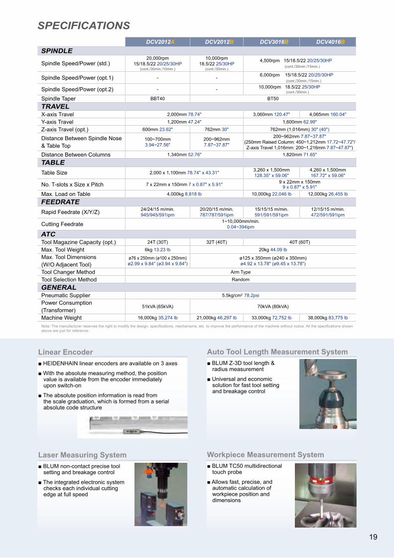
Linear Encoder■ HEIDENHAIN linear encoders are available on 3 axes
■ With the absolute measuring method, the position value is available from the encoder immediately upon switch-on
■ The absolute position information is read from the scale graduation, which is formed from a serial absolute code structure
Laser Measuring System■ BLUM non-contact precise tool setting and breakage control
■ The integrated electronic system checks each individual cutting edge at full speed
Auto Tool Length Measurement System■ BLUM Z-3D tool length & radius measurement
■ Universal and economic solution for fast tool setting and breakage control
Workpiece Measurement System■ BLUM TC50 multidirectional touch probe
■ Allows fast, precise, and automatic calculation of workpiece position and dimensions
DCV2012A DCV2012B DCV3016B DCV4016BSPINDLE
Spindle Speed/Power (std.)20,000rpm
15/18.5/22 20/25/30HP (cont./30min./10min.)
10,000rpm 18.5/22 25/30HP
(cont./30min.)
4,500rpm 15/18.5/22 20/25/30HP (cont./30min./15min.)
Spindle Speed/Power (opt.1) - - 6,000rpm 15/18.5/22 20/25/30HP (cont./30min./15min.)
Spindle Speed/Power (opt.2) - - 10,000rpm 18.5/22 25/30HP (cont./30min.)
Spindle Taper BBT40 BT50
TRAVELX-axis Travel 2,000mm 78.74" 3,060mm 120.47" 4,065mm 160.04"
Y-axis Travel 1,200mm 47.24" 1,600mm 62.99"
Z-axis Travel (opt.) 600mm 23.62" 762mm 30" 762mm (1,016mm) 30" (40")
Distance Between Spindle Nose & Table Top
100~700mm3.94~27.56"
200~962mm7.87~37.87"
200~962mm 7.87~37.87"(250mm Raised Column: 450~1,212mm 17.72~47.72"/Z-axis Travel 1,016mm: 200~1,216mm 7.87~47.87")
Distance Between Columns 1,340mm 52.76" 1,820mm 71.65"
TABLETable Size 2,000 x 1,100mm 78.74" x 43.31" 3,260 x 1,500mm
128.35" x 59.06"4,260 x 1,500mm167.72" x 59.06"
No. T-slots x Size x Pitch 7 x 22mm x 150mm 7 x 0.87" x 5.91" 9 x 22mm x 150mm9 x 0.87" x 5.91"
Max. Load on Table 4,000kg 8,818 lb 10,000kg 22,046 lb 12,000kg 26,455 lb
FEEDRATERapid Feedrate (X/Y/Z) 24/24/15 m/min.
945/945/591ipm20/20/15 m/min.787/787/591ipm
15/15/15 m/min.591/591/591ipm
12/15/15 m/min.472/591/591ipm
Cutting Feedrate 1~10,000mm/min. 0.04~394ipm
ATCTool Magazine Capacity (opt.) 24T (30T) 32T (40T) 40T (60T)
Max. Tool Weight 6kg 13.23 lb 20kg 44.09 lbMax. Tool Dimensions(W/O Adjacent Tool)
ø76 x 250mm (ø100 x 250mm) ø2.99 x 9.84" (ø3.94 x 9.84")
ø125 x 350mm (ø240 x 350mm)ø4.92 x 13.78" (ø9.45 x 13.78")
Tool Changer Method Arm Type
Tool Selection Method Random
GENERALPneumatic Supplier 5.5kg/cm2 78.2psiPower Consumption (Transformer)
51kVA (65kVA) 70kVA (80kVA)
Machine Weight 16,000kg 35,274 lb 21,000kg 46,297 lb 33,000kg 72,752 lb 38,000kg 83,775 lb
Note: The manufacturer reserves the right to modify the design, specifications, mechanisms, etc. to improve the performance of the machine without notice. All the specifications shown above are just for reference.
19
SPECIFICATIONS
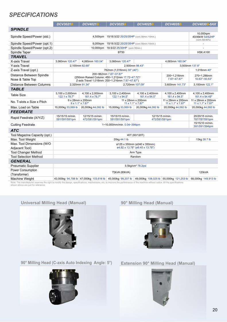
Universal Milling Head (Manual)
90° Milling Head (C-axis Auto Indexing Angle: 5°)
90° Milling Head (Manual)
Extension 90° Milling Head (Manual)
DCV3021B DCV4021B DCV3025B DCV4025B DCV4035B DCV4030B-5AXSPINDLE
Spindle Speed/Power (std.) 4,500rpm 15/18.5/22 20/25/30HP (cont./30min./15min.)10,000rpm
40/46kW 54/62HP(cont./S6-60%)
Spindle Speed/Power (opt.1) 6,000rpm 15/18.5/22 20/25/30HP (cont./30min./15min.) -
Spindle Speed/Power (opt.2) 10,000rpm 18.5/22 25/30HP (cont./30min.) -
Spindle Taper BT50 HSK A100
TRAVELX-axis Travel 3,060mm 120.47" 4,065mm 160.04" 3,060mm 120.47" 4,065mm 160.04"
Y-axis Travel 2,100mm 82.68" 2,500mm 98.43" 3,500mm 137.8"
Z-axis Travel (opt.) 762mm (1,016mm) 30" (40") 1,016mm 40"
Distance Between Spindle Nose & Table Top
200~962mm 7.87~37.87"(250mm Raised Column: 450~1,212mm 17.72~47.72"/
Z-axis Travel 1,016mm: 200~1,216mm 7.87~47.87")
200~1,216mm7.87~47.87"
270~1,286mm10.63"~50.63"
Distance Between Columns 2,320mm 91.34" 2,720mm 107.09" 3,600mm 141.73" 3,100mm 122.1"
TABLETable Size 3,100 x 2,000mm
122.1 x 78.7"4,100 x 2,000mm
161.4 x 78.7"3,100 x 2,400mm
122.1 x 94.5"4,100 x 2,400mm
161.4 x 94.5"4,100 x 2,400mm
161.4 x 94.5"4,100 x 2,400mm
161.4 x 94.49"
No. T-slots x Size x Pitch 9 x 28mm x 200mm9 x 1.1" x 7.87"
11 x 28mm x 200mm11 x 1.1" x 7.87"
11 x 28mm x 200mm11 x 1.1" x 7.87"
11 x 28mm x 200mm11 x 1.1" x 7.87"
Max. Load on Table 15,000kg 33,069 lb 20,000kg 44,092 lb 15,000kg 33,069 lb 20,000kg 44,092 lb 20,000kg 44,092 lb 20,000kg 44,092 lb
FEEDRATERapid Feedrate (X/Y/Z) 15/15/15 m/min.
591/591/591ipm12/15/15 m/min.472/591/591ipm
15/15/15 m/min.591/591/591ipm
12/15/15 m/min.472/591/591ipm
20/20/15 m/min.787/787/591ipm
Cutting Feedrate 1~10,000mm/min. 0.04~394ipm 15/15/10 m/min.591/591/394ipm
ATCTool Magazine Capacity (opt.) 40T (60/120T)
Max. Tool Weight 20kg 44.1 lb 13kg 28.7 lbMax. Tool Dimensions (W/O Adjacent Tool)
ø125 x 350mm (ø240 x 350mm) ø4.92 x 13.78" (ø9.45 x 13.78")
Tool Changer Method Arm Type
Tool Selection Method Random
GENERALPneumatic Supplier 5.5kg/cm2 78.2psiPower Consumption (Transformer)
72kVA (80kVA) 120kVA
Machine Weight 43,000kg 94,798 lb 47,000kg 103,616 lb 45,000kg 99,207 lb 49,000kg 108,025 lb 55,000kg 121,253 lb 68,000kg 149,913 lbNote: The manufacturer reserves the right to modify the design, specifications, mechanisms, etc. to improve the performance of the machine without notice. All the specifications shown above are just for reference.
19 20

OPERATIONOPERATION
CONTROLby
User-friendly G-menu function provides multiple machining cycles that greatly simplifies programming steps
Detailed troubleshooting procedures will be automatically displayed when machine alarm occurs that allows users to restore machine status and minimize down time
Comprehensive tool data management function allows operators to monitor and manage all positions in tool magazine
Intelligent Tool Data Management
Pre-set macros and graphical procedure are provided for automatic tool length measurement function
Automatic Tool LengthMeasurement
Easy setup of tool length measurement provides convenient settingof tool offsets data fromone tool to another
Manual Tool LengthMeasurement
Easy to use conversational software offers convenience of part programming right on the shop-floor with 3D graphical display and full simulation function
Pre-set maintenanceschedules are programmedto remind operators toinspect periodicallyprolonging machine life
Intelligent MaintenanceReminder
Allows user to easily keep track on number of workpieces with:Main CounterPeriodical CounterDaily CounterOver Cycle Alarm
Counter Function
Pop-up Alarm Display
Convenient calculator function provides fast calculation and setting of workpiece offsets
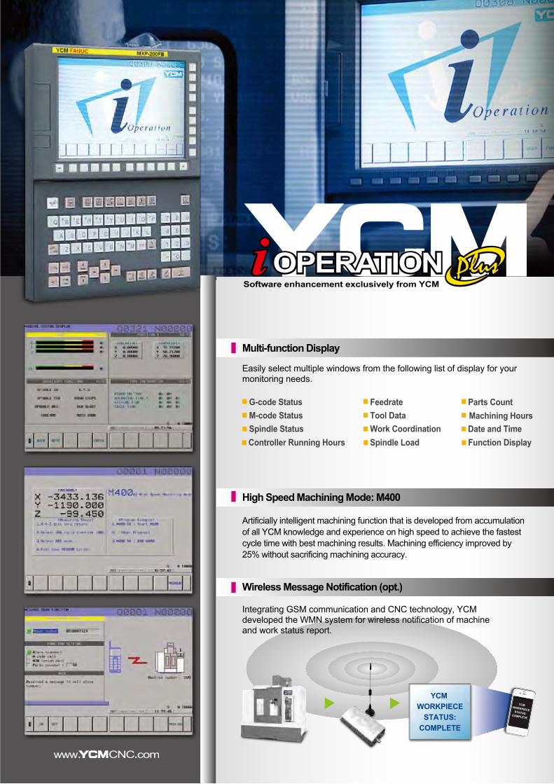
Artificially intelligent machining function that is developed from accumulation of all YCM knowledge and experience on high speed to achieve the fastest cycle time with best machining results. Machining efficiency improved by 25% without sacrificing machining accuracy.
Easy Shop-floor ProgrammingManual Guide i
G-menu Function Calculator Function
Easily select multiple windows from the following list of display for your monitoring needs.
Tool DataWork Coordination
Parts CountMachining Hours
G-code StatusM-code StatusSpindle Status
Multi-function Display
High Speed Machining Mode: M400
Wireless Message Notification (opt.)
Integrating GSM communication and CNC technology, YCM developed the WMN system for wireless notification of machine and work status report.
Date and TimeController Running Hours Spindle Load Function Display
Software enhancement exclusively from YCM
Combined with artificial intelligence, M400 provides users more convenient and easier ways of operation and achieves fast cycle time for the best machining result.
High Speed Machining Mode: M400
Feedrate
YCMWORKPIECESTATUS:COMPLETE
High Performance AC Digital Servo & Spindle Drives with Super Precision Absolute Positioning EncodersAI NANO CNC Controller for High Precision Operation in Nanometers and Acknowledged HRV ControlAICC II High Speed High Accuracy JERK Function & Auto Switching on/off Machining Control FunctionHigh Speed High Accuracy Rigid Tapping, Helical Interpolation, Custom Marco B, and Tool Path GraphicsManual Guide i with Big & Double Screen Display (MXP-200FC, opt.)Program File Management for Easy Program ClassifyingUSB Drive Port for Easy Parameters & CNC Programs TransferLarge Program Capacity with 1,280 Meters of MemoryHigh Speed Positioning Function (MXP-200FC, opt.)Memory Card Program Edit & Operation (opt.)3D Interference Check (opt.)NANO Smooth (opt.)
1. The manufacturer reserves the right to modify the design, specifications, mechanisms, etc. to improve the performance of the machine without notice. All the specifications shown above are just for reference.2. The functions of the controllers will be distinct due to different model and selectivity.
OPERATIONOPERATION
CONTROLby
User-friendly G-menu function provides multiple machining cycles that greatly simplifies programming steps
Detailed troubleshooting procedures will be automatically displayed when machine alarm occurs that allows users to restore machine status and minimize down time
Comprehensive tool data management function allows operators to monitor and manage all positions in tool magazine
Intelligent Tool Data Management
Pre-set macros and graphical procedure are provided for automatic tool length measurement function
Automatic Tool LengthMeasurement
Easy setup of tool length measurement provides convenient settingof tool offsets data fromone tool to another
Manual Tool LengthMeasurement
Easy to use conversational software offers convenience of part programming right on the shop-floor with 3D graphical display and full simulation function
Pre-set maintenanceschedules are programmedto remind operators toinspect periodicallyprolonging machine life
Intelligent MaintenanceReminder
Allows user to easily keep track on number of workpieces with:Main CounterPeriodical CounterDaily CounterOver Cycle Alarm
Counter Function
Pop-up Alarm Display
Convenient calculator function provides fast calculation and setting of workpiece offsets
Artificially intelligent machining function that is developed from accumulation of all YCM knowledge and experience on high speed to achieve the fastest cycle time with best machining results. Machining efficiency improved by 25% without sacrificing machining accuracy.
Easy Shop-floor ProgrammingManual Guide i
G-menu Function Calculator Function
Easily select multiple windows from the following list of display for your monitoring needs.
Tool DataWork Coordination
Parts CountMachining Hours
G-code StatusM-code StatusSpindle Status
Multi-function Display
High Speed Machining Mode: M400
Wireless Message Notification (opt.)
Integrating GSM communication and CNC technology, YCM developed the WMN system for wireless notification of machine and work status report.
Date and TimeController Running Hours Spindle Load Function Display
Software enhancement exclusively from YCM
Combined with artificial intelligence, M400 provides users more convenient and easier ways of operation and achieves fast cycle time for the best machining result.
High Speed Machining Mode: M400
Feedrate
YCMWORKPIECESTATUS:COMPLETE
High Performance AC Digital Servo & Spindle Drives with Super Precision Absolute Positioning EncodersAI NANO CNC Controller for High Precision Operation in Nanometers and Acknowledged HRV ControlAICC II High Speed High Accuracy JERK Function & Auto Switching on/off Machining Control FunctionHigh Speed High Accuracy Rigid Tapping, Helical Interpolation, Custom Marco B, and Tool Path GraphicsManual Guide i with Big & Double Screen Display (MXP-200FC, opt.)Program File Management for Easy Program ClassifyingUSB Drive Port for Easy Parameters & CNC Programs TransferLarge Program Capacity with 1,280 Meters of MemoryHigh Speed Positioning Function (MXP-200FC, opt.)Memory Card Program Edit & Operation (opt.)3D Interference Check (opt.)NANO Smooth (opt.)
1. The manufacturer reserves the right to modify the design, specifications, mechanisms, etc. to improve the performance of the machine without notice. All the specifications shown above are just for reference.2. The functions of the controllers will be distinct due to different model and selectivity.

sales@886-4-2562-8399
GENERAL TEL : 886-4-2562-3211FAX : 886-4-2562-6479 FAX : 886-4-2561-2966
SERVICE TEL : 886-4-2561-2965Headquarters :
YEONG CHIN MACHINEYEONG CHIN MACHINERYRY INDUSTRIES CO., INDUSTRIES CO., LTD
102012-E04-2000
LTD.
888, Homu Road, Shengang District, Taichung, 42953, Taiwan