Embed Size (px)
Citation preview

8/8/2019 September 2005 Geo-Heat Center Quarterly Bulletin
http://slidepdf.com/reader/full/september-2005-geo-heat-center-quarterly-bulletin 1/28
ISSN 0276
Vol. 26, No. 3 SEPTEMBER 2005
ChiloquinCommunity Center
CalpineGeothermal Visitor Center
Canyon View High School
Murray High School
Sundown M Ranch
Inn at theSeventh
Mountain
South Cariboo Recreation
Centre
100 Mile House
Yakima
Bend
Chiloquin
Middletown Salt Lake City
Cedar City
GEO-HEAT CENTER Quarterly Bulletin
OREGON INSTITUTE OF TECHNOLOGY – KLAMATH FALLS, OREGON 97601-8801PHONE NO. (541) 885-1750
GeothermalHeat Pump
Case Studiesof the West

8/8/2019 September 2005 Geo-Heat Center Quarterly Bulletin
http://slidepdf.com/reader/full/september-2005-geo-heat-center-quarterly-bulletin 2/28
Vol. 26, No. 3 September 2005
GEO-HEAT CENTER QUARTERLY BULLETINISSN 0276-1084
A Quarterly Progress and Development Report
on the Direct Utilization of Geothermal Resources
CONTENTS
Geothermal Heat Pump
Case Studies of the West
Calpine Geothermal Visitor
Center, Middletown, CaliforniaAndrew Chiasson
Canyon View High School,
Cedar City, UtahAndrew Chiasson
Murray High School,
Salt Lake City, UtahAndrew Chiasson
Chiloquin Community Center,
Chiloquin, OregonAndrew Chiasson
South Cariboo Recreation
Centre, 100 Mile House,
British Columbia, CanadaEd Lohrenz
Sundown M Ranch,
Yakima, WashingtonDr. R. Gordon Bloomquist
Inn of the Seventh Mountain,
Bend, OregonDr. R. Gordon Bloomquist
Cover: The following case studies
were developed at the request of theUSDOE National Renewable Energy
Laboratory (NREL) to provide a thumb-
nail description of a cross section of
geothermal heat pump projects in the
western U.S.
Page
1
2
5
9
12
15
21
24
PUBLISHED BY
GEO-HEAT CENTER Oregon Institute of Technology
3201 Campus Drive
Klamath Falls, OR 97601
Phone: 541-885-1750Email: [email protected]
All articles for the Bulletin are solicited. If you
wish to contribute a paper, please contact the
editor at the above address.
EDITOR
John W. Lund
Typesetting/Layout/Graphics
Tonya “Toni” Boyd
WEBSITE http://geoheat.oit.edu
FUNDING
The bulletin is provided compliments of the Geo-
Heat Center. This material was prepared with the
support of the U.S. Department of Energy (DOE
Grant No. DE-FG03-01SF22362). However, anyopinions, findings, conclusions, or
recommendations expressed herein are those of theauthors(s) and do not necessarily reflect the view
of USDOE.
SUBSCRIPTIONS
The Bulletin is mailed free of charge. Please send
your name and address to the Geo-Heat Center for
addition to the mailing list.
If you wish to change your bulletin subscription,
please complete the form below and return it to theCenter.
Name ___________________________________
Address _________________________________
___________________________ Zip __________
Country _________________________________

8/8/2019 September 2005 Geo-Heat Center Quarterly Bulletin
http://slidepdf.com/reader/full/september-2005-geo-heat-center-quarterly-bulletin 3/28
GHC BULLETIN, SEPTEMBER 2005 1
GEOTHERMAL HEAT PUMP
CASE STUDIES OF THE WEST
Geothermal (ground-source) heat pumps (GHPs)have become a major growth area of geothermal energy use
in the United States, Canada and Europe. Within the UnitedStates; however, according to geothermal heat pumpshipment tracking by the Energy Information Administration(EIA), the west only represents 9% of the total GHPshipments. Thus, this issue of the Geo-Heat Center Quarterly Bulletin is devoted to seven examples of GHPs inthe western regions of Canada and the United States. Twoare open-loop (groundwater) types and five are closed-loop(ground-coupled) types. We have attempted to includeoperating and maintenance experiences along with theassociated costs.
The number of GHPs has steadily increased over the past 10 years with an estimated 600,000 to 800,000
equivalent 12 kW (3.4 ton) units installed in the UnitedStates and 36,000 in Canada. They have been reportedinstalled in all the states in the U.S. and all the provinces inCanada. We estimated that 60,000 units were installed inthe U.S. and over 3,000 in Canada this past year. The U.S.units are mainly found in the Midwestern and Eastern states,and the Canadian units in Ontario and Manitoba withconsiderable growth in British Columbia. Of the installedunits, we estimate that 44% are vertical closed-loop, 36% arehorizontal closed-loop and 20% are open-loop systems.Interest in open-loop systems appears to be increasing,accounting for 25% of the units shipped from manufacturersthis past year.
Using an average unit size of 12 kW (3.4 tons), theinstalled capacity in the U.S. is between 7,200 and 9,600MWt, and based on approximately 1,200 full-load equivalentoperating hours per year and a coefficient of performance(COP) of 3.5, the annual energy removed from the ground is between 6,171 and 8,228 GWh (21,060 and 28,080 billionBtu). The corresponding figures for Canada are 396 MWtand 600 GWh/yr (2,048 billion Btu). World-wide, 33countries report the use of GHPs (from the WorldGeothermal Congress 2005). It is estimated that there are1.7 million units installed world-wide, accounting for aninstalled capacity of 15,384 MWt and annual energy use of 24,300 GWh (82,960 billion Btu). In the United States,
most systems are designed for the cooling load, whereas inEurope they are designed to provide base-load heating, and
average an equivalent 2,200 full-load operating hoursannually. Cooling load cannot be considered geothermal, aheat is rejected to the ground or ground-water; howevercooling has a role in the substitution for fossil fuels andreduction of greenhouse gas emissions.
As reported in our March 2001 (Vol. 22, No. 1)issue of the Quarterly Bulletin, President George W. Bushinstalled a geothermal heat pump on his Texas ranch. Theunit is 49 kW (14 tons) broken into five separate systemswith desuperheater. The vertical closed loop installationcuts his heating and cooling cost by 40%. On the other sideof the Atlantic, the Sunday Times of London (August 212005 by Lois Rogers), reports that the Queen of England is
planning to install a GHP for heating and to cut energy billat Buckingham Palace. A closed-loop system placed belowthe surface of a four-acre (1.6 ha) lake will provide heatingto state rooms and the formal area of the palace. The heawill be provided through either radiators, or by venting hotair through underfloor heating. The system will cosapproximately ₤50,000 (US$90,000) to install the outdoorequipment, and several hundred thousands additional Pounds(₤) to make the system compatible with the existing palaceheating system. This is estimated to reduce the heating andelectricity bills by at least 70%. A trial system was installedin 2002 by drilling 400 feet into the chalk aquifer beneaththe palace ground to run an air-conditioning system for anew art gallery, built at Buckingham Palace to mark thegolden jubilee for the Queen. The results were impressiveand led to the current project that will replace conventionalheating sources for part of the palace.
Other famous persons from the United Kingdomwho have installed GHPs are Sir Elton John, the pop star, SirRichard Branson, the entrepreneur, Paul Allen, the billionaire co-founder of Microsoft, George Davies, the highstreet fashion guru, and Paul Lister, son of the found of theMFI furniture empire and owner of a vast Highlands naturereserve.
The Editor

8/8/2019 September 2005 Geo-Heat Center Quarterly Bulletin
http://slidepdf.com/reader/full/september-2005-geo-heat-center-quarterly-bulletin 4/28
2 GHC BULLETIN, SEPTEMBER 2005
CALPINE GEOTHERMAL VISITOR CENTER
MIDDLETOWN, CALIFORNIA
Andrew Chiasson
Geo-Heat Center
LOCATION & BACKGROUND
The Calpine Geothermal Visitor Center is locatedin Middletown, California, about 70 miles (113 km) north of San Francisco. It is a single-story, 6,000 ft2 (560 m2)building and is the visitor center for The Geysers geothermalfield, the largest geothermal power generating operation inthe world. The visitor center building has incorporated anumber of “green” features, one of which is a geothermalheat pump system. Completed in 2001, the building has alobby area, an exhibit hall featuring geothermal power
displays, small offices, a conference room, a kitchen, and amultipurpose room (Figure 1).Average high temperatures in the area in July are
about 92oF (33.3oC) and average low temperatures inJanuary are about 35oF (1.7oC). There are approximately2800 heating degree days and 800 cooling degree days peryear [65 oF (18oC) base].
SYSTEM DESCRIPTION
Ground Source SystemThe ground source system (shown in Figure 1) is
the vertical closed loop type consisting of 20 verticalboreholes, each 225 ft (69 m) deep, for a total length of 4500ft (1372 m). The boreholes are installed in a 4 x 5 grid
pattern with 20-ft (6.1-m) spacing. A single u-tube heatexchanger is installed in each borehole and the heat transferfluid is pure water. The borehole field is piped in a reverse-return arrangement.
The mean annual ground temperature in thislocation is about 62oF (16.7oC). The loop field was installedin an alluvial fan deposit, consisting of cobbles and boulders.
Figure 1. Calpine Visitor Center site sketch
showing ground loop field.
EXHIBITHALL
CONF.RM.
MULTI-PURPOSE
RM.KITCHEN
MAIN ENTRY
LOBBYAREA
OFF.
RESTRM.
N
ENTRY
20 FT
4 x 5VERTICAL BOREHOLE FIELD
(note only supply piping is shown)
~
~EXHIBIT
HALL
CONF.RM.
MULTI-PURPOSE
RM.KITCHEN
MAIN ENTRY
LOBBYAREA
OFF.
RESTRM.
NN
ENTRY
20 FT
4 x 5VERTICAL BOREHOLE FIELD
(note only supply piping is shown)
~
~

8/8/2019 September 2005 Geo-Heat Center Quarterly Bulletin
http://slidepdf.com/reader/full/september-2005-geo-heat-center-quarterly-bulletin 5/28
GHC BULLETIN, SEPTEMBER 2005 3
Interior SystemThe total installed heat pump capacity is
approximately 25 tons (88 kW). As each room in thebuilding has a different use and variable occupancy rate, thebuilding was designed so that each room is a separate zone.Space conditioning for the lobby, offices, and exhibit hall isaccomplished with vertical water-to-air heat pumps installedin closet spaces. Space conditioning for the other areas(conference rooms, hallways, restrooms, and kitchen) isdone with horizontal water-to-air heat pumps hidden in theattic. Ventilation air is ducted through the attic space toindividual heat pumps. A 1 ton water-to-water heat pumpinstalled in the kitchen is used for domestic hot waterheating. For energy efficient pumping, a separate water
circulator is installed on each heat pump. A schematic of atypical heat pump layout is shown in Figure 2, and aphotograph of the 6-ton (21 kW), vertical unit and flowcenter serving the exhibit hall is shown in Figure 3.
PROJECT COSTS
The total geothermal heat pump heatingventilating, and air-conditioning (HVAC) system cost in2001 was $78,000, or approximately $13/ft2 ($140/m2)From Means construction cost data (2000), the medianHVAC system cost for a similar building (a communitycenter) is $9/ft2 ($97/m2). Therefore, it is estimated that thegeothermal heat pump system capital cost was about 44%, or$24,000 greater than a conventional system.
Figure 2. Schematic of a typical heat pump at the Calpine Visitor Center.
Figure 3. Photograph of a 6-ton, water-air, vertical
heat pump and flow center.
SYSTEM PERFORMANCE AND OPERATING COST
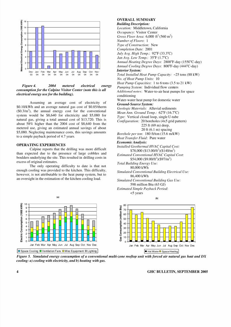
Electrical energy consumption for the CalpineVisitor system for the year 2004 is shown in Figure 4. Thedata shown in Figure 4 represent the total electrical energyconsumption for the building, and therefore the exact HVACsystem energy use is not known. The total electrical energyconsumption for 2004 was 80,120 kWh.
In order to compare performance of the geothermaheat pump system to a conventional HVAC system, thebuilding performance was simulated using eQuest, whichemploys the DOE-2 building simulation engine. For thissimulation, building use and occupancy profiles for acommunity center were chosen. The conventional HVACsystem modeled was a multi-zone rooftop unit with forced-
air natural gas heating and DX cooling.Results of the simulated energy consumption of theconventional system are shown in Figure 5. A review ofFigure 5 shows that a conventional HVAC system at theCalpine Visitor Center would consume a total of 86,400kWh of electrical energy and a total of 597.65 million Btu(63 GJ) of natural gas.
TO/FROM
GROUND LOOP
FLOW
CENTER
w. 2 circulators
WATER-AIR
HEAT PUMP
SUPPLY
AIRRETURN
AIR
EXHAUST
AIR
FRESH OUTDOOR
AIRTO/FROM
GROUND LOOP
FLOW
CENTER
w. 2 circulators
WATER-AIR
HEAT PUMP
SUPPLY
AIRRETURN
AIR
EXHAUST
AIR
FRESH OUTDOOR
AIR
8/8/2019 September 2005 Geo-Heat Center Quarterly Bulletin
http://slidepdf.com/reader/full/september-2005-geo-heat-center-quarterly-bulletin 6/28
4 GHC BULLETIN, SEPTEMBER 2005
(a)
0
1
2
3
4
5
6
7
8
9
10
Jan Feb Mar Apr May Jun Jul Aug Sep Oct Nov Dec
E l e c t r i c C o n s u m
p t i o n ( 1 0 0 0 k W h )
Space Cooling Ventilation Fans Misc Equipment Lighting
(b)
0
10
20
3040
50
60
70
80
Jan Feb Mar Apr May Jun Jul Aug Sep Oct Nov Dec
G a s C o n s u m p t
i o n ( m i l l i o n B t u )
Hot Water Space Heating
Figure 4. 2004 metered electrical energy
consumption for the Calpine Visitor Center (note this is all
electrical energy use for the building).
Assuming an average cost of electricity of $0.10/kWh and an average natural gas cost of $0.85/therm
($0.3/m
3
), the annual energy cost for the conventionalsystem would be $8,640 for electricity and $5,080 fornatural gas, giving a total annual cost of $13,720. This isabout 58% higher than the 2004 cost of $8,640 from themetered use, giving an estimated annual savings of about$5,080. Neglecting maintenance costs, this savings amountsto a simple payback period of 4.7 years.
OPERATING EXPERIENCES
Calpine reports that the drilling was more difficultthan expected due to the presence of large cobbles andboulders underlying the site. This resulted in drilling costs inexcess of original estimates.
The only operating difficulty to date is that notenough cooling was provided to the kitchen. This difficulty,however, is not attributable to the heat pump system, but toan oversight in the estimation of the kitchen cooling load.
OVERALL SUMMARY
Building Description:
Location: Middletown, CaliforniaOccupancy: Visitor CenterGross Floor Area: 6,000 ft2 (560 m2) Number of Floors: 1Type of Construction: NewCompletion Date: 2001 July Avg. High Temp.: 92oF (33.3oC) Jan Avg. Low Temp.: 35oF (1.7oC) Annual Heating Degree Days: 2800oF-day (1550oC-day) Annual Cooling Degree Days: 800oF-day (444oC-day) Interior System:
Total Installed Heat Pump Capacity: ~25 tons (88 kW) No. of Heat Pump Units: 10
Heat Pump Capacities: 1 to 6 tons (3.5 to 21 kW)Pumping System: Individual flow centers Additional notes: Water-to-air heat pumps for spaceconditioningWater-water heat pump for domestic waterGround-Source System:
Geologic Materials: Alluvial sediments
Mean Ann. Ground Temp.: 62oF (16.7oC) Type: Vertical closed loop, single U-tubeConfiguration: 20 boreholes (4x5 grid pattern)
225 ft (69 m) deep,20 ft (6.1 m) spacing
Borehole per ton: 180 ft/ton (15.6 m/kW) Heat Transfer Fluid : Pure water Economic Analysis:
Installed Geothermal HVAC Capital Cost: $78,000 ($13.00/ft2)($140/m2)
Estimated Conventional HVAC Capital Cost :$54,000 ($9.00/ft2)($97/m2)
Total Building Energy Use:
80,000 kWhSimulated Conventional Building Electrical Use:
86,400 kWhSimulated Conventional Building Gas Use:
598 million Btu (63 GJ) Estimated Simple Payback Period :
<5 years
Figure 5. Simulated energy consumption of a conventional multi-zone rooftop unit with forced air natural gas heat and DX
cooling: a) cooling with electricity, and b) heating with gas.
0
2
4
6
8
10
12
14
16
Dec-
03
Jan-
04
Feb-
04
Mar-
04
Apr-
04
May-
04
Jun-
04
Jul-
04
Aug-
04
Sep-
04
Oct-
04
Nov-
04
M e t e r e d E l e c t r i c
a l E n e r g y C o n s u m p t i o n ( 1 0 0 0 k W h )

8/8/2019 September 2005 Geo-Heat Center Quarterly Bulletin
http://slidepdf.com/reader/full/september-2005-geo-heat-center-quarterly-bulletin 7/28
CANYON VIEW HIGH SCHOOL
CEDAR CITY, UTAH
Andrew Chiasson
Geo-Heat Center
LOCATION & BACKGROUNDThe Canyon View High School is located in Cedar
City, UT, about 90 miles (145 km) northeast of the point of intersection of Utah, Arizona, and Nevada. It is a two-story building with 233,199 ft2 (21,665 m2) of floor space, andconstruction was completed in 2001.
Average high temperatures in the region in July areabout 93oF (33.9oC) and average low temperatures inJanuary are about 15oF (-9.4oC). There are approximately6100 (3390oC-day) heating degree days and 700 (390oC-day) cooling degree days per year [65 oF (18oC) base].
The Canyon View ground-source heat pump systemis considered the first “large” geoexchange system in theCentral Rocky Mountain Region.
SYSTEM DESCRIPTION
Ground Source System
The ground source system (Figure 1) is the verticalclosed loop type consisting of 300 vertical boreholes, each
300 ft (91.4 m) deep, for a total length of 90,000 ft (27,432m). The boreholes, installed under the school playing field,are placed in a 15 x 20 grid pattern with a 20-ft (6.1-m) borehole spacing and 25-ft (7.6-m) spacing between run-outs. A single u-tube heat exchanger is installed in each borehole, and the borehole field is piped in a reverse-returnarrangement.
The mean annual ground temperature in thislocation is approximately 53oF (11.7oC). An in-situ thermal
conductivity test revealed that the average thermaconductivity of the soil to a depth of 300 ft (91.4 m) is 1.19Btu/hr-ft-oF (2.06 W/m-oC). The loop field was installed in basin-fill type sediments, consisting of coarse sand angravel with clay stringers and trace volcanics. Interior System
The total installed heat pump capacity at theCanyon View High School is approximately 550 tons (1953kW). Space conditioning is accomplished by over 100 waterair heat pumps, which are installed in ceiling spaces to serveindividual classrooms and other zones. Outdoor air isintroduced through heat recovery ventilator (HRV) unitsThe original design called for total energy recovery (ERV)units, but HRV’s were installed due their to lower costThere is little use of domestic hot water in the school, andthus it is generated partially by water-water heat pumps andnatural-gas water heaters. The fluid distribution systemconsists of a central pumping system with a variablefrequency drive.
A generalized schematic of the system is shown inFigure 2. Figure 3 is a photograph of the ground-loopheaders in the mechanical room and Figure 4 is a photographof a typical horizontal, ceiling-mounted water-air heat pump
PROJECT COSTSThe Canyon View High School is an example of a
building where a ground-source heat pump system wa
GHC BULLETIN, SEPTEMBER 2005 5

8/8/2019 September 2005 Geo-Heat Center Quarterly Bulletin
http://slidepdf.com/reader/full/september-2005-geo-heat-center-quarterly-bulletin 8/28
Figure 1. Canyon View High School ground loop field.
Figure 2. Schematic of the ground-source heat pump system at the Canyon View High School.
6 GHC BULLETIN, SEPTEMBER 2005

8/8/2019 September 2005 Geo-Heat Center Quarterly Bulletin
http://slidepdf.com/reader/full/september-2005-geo-heat-center-quarterly-bulletin 9/28
cheaper to install than a conventional boiler chiller system.The project costs are summarized as follows:
• Conventional Mechanical System Bid:$17.00/ft2 ($183.00/m2)
• Canyon View High School Ground Source System Bid:Mechanical/Plumbing bid: $2,457,000
GHC BULLETIN, SEPTEMBER 2005 7
Loop Field bid: $778,000Total Ground Source bid: $3,235,000
Mechanical Cost/ft2
(m2
): $13.87/ft2
($149.30/m2
)Cost Savings: $3.13/ ft2 ($33.69/m2) = $729,000
Additional cost savings may be realized if oneconsiders architectural savings in the mechanical room floor space in the ground-source system over the conventionalsystem. For the Canyon View High School, the mechanicalroom for the ground-source system is 2,680 ft2 (249 m2), or 1.15% of the total floor space. Comparing this value to3.80% of mechanical room floor space to total floor spacefor average schools, and assuming $50/ft2 ($538/m2) cost of new construction, an additional savings of $309,000 may berealized.
Figure 3. Photograph of the mechanical room at the
Canyon View High School, showing the ground loop field
supply and return headers.
SYSTEM PERFORMANCE AND OPERATING COSTThe system has performed as designed. Maximum
ground loop temperatures observed in the summer are about
92oF (33.3oC) and minimum loop temperatures in the winter are 40-42oF (4.4–5.5oC). Annual utility costs for 2001-2002are summarized as follows:
• Annual Utility Costs for Canyon View High School: Electricity: $135,886.54 (96%) Natural Gas: $5,446.87 (4%)Total: $141,333.41Cost/ft2 (m2): $0.61/ft2 ($6.57/m2)
• Utility Costs for a Comparable School:Cost/ft2 (m2): $0.86/ft2 ($9.26/m2)
(77% electrical, 23% gas)• Operating Cost Savings: $0.25/ ft2 ($2.69/m2)
= $58,300 (or 29%)/year
Figure 4. Photograph of a typical horizontal, ceiling
mounted water-air heat pump.
OPERATING EXPERIENCES
Although the geoexchange system at the CanyonView High School is performing well, it is a large system,and the designer admits that there are ways that the pumpingsystem could have been designed to optimize energyconsumption. For example, systems of similar size are beingdesigned with primary/secondary pumping, multiple loop pumps to utilize only as much of the ground loop anecessary, and distributed pumping in the building.
Most heat pumps are installed in ceiling spaces, andaccess has been a bit tight. Dirt and sand was a problem inthe system for about 6 months after start-up, which wasattributed to a damaged header pipe, likely caused bylandscaping work.
ACKNOWLEDGEMENTS
The Geo-Heat Center wishes to thank Cary Smith of SoundGeothermal for providing the data and information for thiscase study
OVERALL SUMMARY
Building Description:
Location: Cedar City, UtahOccupancy: SchoolGross Floor Area: 233,199 ft2 (21,665 m2)
Number of Floors: 2Type of Construction: NewCompletion Date: 2001
July Avg. High Temp.: 93oF (33.9oC) Jan Avg. Low Temp.: 15oF (-9.9oC) Annual Heating Degree Days: 6100oF-day (3390oC-day)

8/8/2019 September 2005 Geo-Heat Center Quarterly Bulletin
http://slidepdf.com/reader/full/september-2005-geo-heat-center-quarterly-bulletin 10/28
8 GHC BULLETIN, SEPTEMBER 2005
Annual Cooling Degree Days: 700oF-day (390oC-day) Interior System:
Total Installed Heat Pump Capacity: ~550 tons (1,935 kW) No. of Heat Pump Units: 100+
Pumping System: Central with VFDGround-Source System:
Geologic Materials: Basin-fill sedimentsMean Ann. Ground Temp.: 53oF (11.7oC) Type: Vertical closed loop, single U-tube
Configuration: 300 boreholes (15x20 grid pattern)300 ft (91.4 m) deep,20 to 25 ft (6.1 to 7.6 m) spacing
Borehole per ton: ~164 ft/ton (14.2 m/kW)
Economic Analysis:
Installed Geothermal HVAC Capital Cost: $3,235,000 ($13.87/ft2)($149.30/m2)
Conventional HVAC Capital Cost Bid :$3,963,363 ($17.00/ft2)($183.00/m2)
Annual HVAC Energy Cost (2001-2002): $141,333 ($0.61/ft2)($6.57/m2)
Annual HVAC Energy Cost of Comparable Conventional
School:
$200,500 ($0.86/ft2
) ($9.26/m2
) Annual HVAC Energy Savings:
29% Estimated Simple Payback Period :
Immediate

8/8/2019 September 2005 Geo-Heat Center Quarterly Bulletin
http://slidepdf.com/reader/full/september-2005-geo-heat-center-quarterly-bulletin 11/28
MURRAY HIGH SCHOOL
SALT LAKE CITY, UTAH
Andrew Chiasson
Geo-Heat Center
LOCATION & BACKGROUND
The Murray High School is located in Murray, UT,which is part of the Salt Lake City metropolitan area. It is atwo-story building with 267,256 ft2 (24,829m2) of floor space, and construction was completed in 2003.
Average high temperatures in the region in July areabout 91oF (32.8oC) and average low temperatures inJanuary are about 21oF (-6.1oC). There are approximately5600 heating degree days (3110oC-day) and 1100 coolingdegree days (610oC-day) per year [65 oF (18oC) base].
SYSTEM DESCRIPTION
Ground Source System
The ground source system (Figure 1) is a “hybridsystem”, consisting of vertical, closed-loop ground heatexchangers and a supplementary fluid cooler to balance theannual ground loads (since summer occupancy of the schoolwas expected). The ground loop is comprised of 316 vertical boreholes, each 300 ft (91.4 m) deep, for a total length of 94,800 ft (28,895 m). It is installed under the north parkinglot of the school, and the boreholes are placed in a grid-like pattern consisting of 5 sub-fields for easier flushing and purging. A single u-tube heat exchanger is installed in each borehole, and the borehole sub-fields are piped in a reverse-return arrangement. A photograph of the supplementaryfluid cooler is shown in Figure 2. The fluid cooler capacityis 125 tons (440 kW).
The mean annual ground temperature in thislocation is approximately 53oF (11.7oC). An in-situ thermaconductivity test revealed that the average thermaconductivity of the soil to a depth of 300 ft (91.4 m) is 1.13Btu/(hr-ft-oF)(1.95 W/m-oC). The loop field was installed in
basin-fill type sediments, consisting of clay, sand, and gravewith cobble stringers. Interior System
The total installed heat pump capacity at the Murray HighSchool is approximately 650 tons (2286 kW). Spaceconditioning is accomplished by over 100 water-air heat pumps, which are installed in ceiling spaces to serveindividual classrooms and other zones. Outdoor air isintroduced through heat recovery ventilator (HRV) units.The original design called for total energy recovery (ERV)units, but HRV’s were installed due their to lower cost.There is little use of domestic hot water in the school, andthus it is generated partially by water-water heat pumps andnatural-gas water heaters. The fluid distribution systemconsists of a central pumping system with a variablefrequency drive. Figure 3 is a photograph of the ground-loopheaders in the main mechanical room.
PROJECT COSTS
The Murray High School is an example of a building where a ground-source heat pump system wacheaper to install than a conventional boiler chiller systemThe project costs are summarized as follows:
GHC BULLETIN, SEPTEMBER 2005 9

8/8/2019 September 2005 Geo-Heat Center Quarterly Bulletin
http://slidepdf.com/reader/full/september-2005-geo-heat-center-quarterly-bulletin 12/28
Figure 1. Murray High School ground loop field.
• Conventional Mechanical System Bid:$19.00/ft2 ($204.50/m2)
• Murray High School Ground Source System Bid:Mechanical/Plumbing bid: $3,065,161Loop Field bid: $930,784
10 GHC BULLETIN, SEPTEMBER 2005
Total Ground Source bid: $3,995,945Mechanical Cost/ft2 (m2): $14.95/ft2 ($160.92/m2)
Cost Savings: 4.05/ ft2 ($43.59/m2) = $1,082,387
Additional cost savings may be realized if oneconsiders architectural savings in the mechanical roomfloor space in the ground-source system over theconventional system. For the Murray High School, themechanical room for the ground-source system is 2,160 ft2 (200.7 m2), or 0.8% of the total floor space. Comparing thisvalue to 3.80% of mechanical room floor space to totalfloor space for average schools, and assuming $50/ft2 ($538.20/m2) cost of new construction, an additionalsavings of $405,000 may be realized
SYSTEM PERFORMANCE AND OPERATING COSTMaximum ground loop temperatures observed in
the summer are about 92oF (33.3oC), and minimum looptemperatures in the winter are 40-42oF (4.4-5.5oC).According to the designers of the system, to their
knowledge, the fluid cooler has not yet been needed.Annual utility costs for 2003-2004 are summarized as
follows:
Figure 2. Photograph of the fluid cooler at the
Murray High School.

8/8/2019 September 2005 Geo-Heat Center Quarterly Bulletin
http://slidepdf.com/reader/full/september-2005-geo-heat-center-quarterly-bulletin 13/28
• Annual Utility Costs for Canyon View High School: Electricity: $156,505 (96%) Natural Gas: $6,521 (4%)Total: $163,026Cost/ft2 (m2): $0.61/ft2 ($6.57/m2)
• Utility Costs for a Comparable School:Cost/ft2 (m2): $0.86/ft2 ($9.26/m2)
(77% electrical, 23% gas)• Operating Cost Savings:
$0.25/ ft2
($2.69/m2
) = $58,300 (or 29%)/year
GHC BULLETIN, SEPTEMBER 2005 11
Figure 3. Photograph of the main mechanical
room at the Murray High School, showing the ground
loop field supply and return headers.
OPERATING EXPERIENCESThus far, the system has operated well, with the
only difficulties being those typical at start-up, such astrapped air and some mud in the ground loop.
ACKNOWLEDGEMENTSThe Geo-Heat Center wishes to thank Cary Smith
of Sound Geothermal for providing the data andinformation for this case study.
OVERALL SUMMARY
Building Description:
Location: Salt Lake City, UtahOccupancy: SchoolGross Floor Area: 267,256 ft2 (24,829 m2)
Number of Floors: 2Type of Construction: NewCompletion Date: 2003
July Avg. High Temp.: 91oF (32.8oC)
Jan Avg. Low Temp.: 21o
F (-6.1o
C) Annual Heating Degree Days: 5600oF-day (3110oC-day) Annual Cooling Degree Days: 1100oF-day (610oC-day) Interior System:
Total Installed Heat Pump Capacity: 650 tons (2,286 kW) No. of Heat Pump Units: 100+
Pumping System: Central with VFDGround-Source System:
Geologic Materials: Basin-fill sedimentsMean Ann. Ground Temp.: 53oF (11.7oC) Type: Hybrid, vertical closed loop, single U-tubeConfiguration: 316 boreholes (grid-like pattern in 5 sub-
fields),
300 ft (91.4 m) deep + fluid cooler Borehole per ton: 146 ft/ton (12.6 m/kW) Economic Analysis:
Installed Geothermal HVAC Capital Cost: $3,995,945 ($14.95/ft2)($160.92/m2)
Conventional HVAC Capital Cost Bid :$5,077,864 ($19.00/ft2)($204.50/m2)
Annual HVAC Energy Cost (2003-2004): $163,026 ($0.61/ft2)
Annual HVAC Energy Cost of Comparable Conventiona
School: $229,840 ($0.86/ft2) ($9.26/m2) Annual HVAC Energy Savings:
29% Estimated Simple Payback Period :
Immediate

8/8/2019 September 2005 Geo-Heat Center Quarterly Bulletin
http://slidepdf.com/reader/full/september-2005-geo-heat-center-quarterly-bulletin 14/28
CHILOQUIN COMMUNITY CENTER
CHILOQUIN, OREGON
Andrew Chiasson
Geo-Heat Center
LOCATION & BACKGROUND
The Chiloquin Community Center is located inChiloquin, Oregon, which is in southern Oregon, about 30miles (48 km) north of Klamath Falls, and about 250 miles(402 km) south of Portland. It is a single-level, 13,000 ft2 (1,210 m2) structure that provides space for the ChiloquinPublic Library, the Two Rivers Art Gallery, public arts andcrafts work-rooms, a large public meeting room with fullkitchen, and also leases offices to the local Sheriff’sDepartment. Portions of the building are in use 7 days per
week, year round. A sketch of the building footprint and borefield are shown in Figure 1.
The building is constructed of insulated concreteform (ICF) walls and a conventional wood frame roof. As aconsequence of using ICF with fixed windows, the buildingis extremely well insulated and air-tight. The entire slab isinsulated using 1-inch polystyrene board to reducedownward heat loss in winter.
12 GHC BULLETIN, SEPTEMBER 2005
Figure 1. Chiloquin Community Center site sketch
showing ground loop field.
The building was constructed in 2003-2004, andformally opened in the Spring of 2004. The ground-sourceheat pump system installation began prior to thecommencement of the main building with the drilling of thenetwork of vertical bores comprising the earth heatexchanger for the facility.
Average high temperatures in the area in July areabout 85oF (29.4oC) and average low temperatures inJanuary are about 22oF (-5.6oC). There are approximately7000 (3890oC-day) heating degree days and 200 (110oC-
day) cooling degree days per year (65 oF (18oC) base).
SYSTEM DESCRIPTION
Ground Source System
The ground source system (shown in Figure 1) is avertical network of 16 bores, each 6-inch (152-mm) diameter and 320 ft (98 m) deep, and arranged in a rectangular gridwith a bore-to-bore spacing of 20 ft (6.1 m). The u-tubeassemblies were fabricated using 1” (25.4 mm) diameter high-density polyethylene pipe (HDPE). Following insertionof the u-tubes, a bentonite/silica sand grout was pumped intothe bores to achieve a nominal grout thermal conductivity of 1.0 Btu/hr-ft-oF (1.7 W/m-oC).
Meeting Hall
Library ArtGallery
Lobby
To aid in the design of the borefield, an in-situthermal conductivity analysis was performed on a test bore.The resulting test data were used to determine that theaverage thermal conductivity of the earth surrounding the bore is approximately 0.62 Btu/hr-ft-oF (1.07 W/m-oC). Themean earth temperature was measured at 56oF (13.3oC).
The geology at the site, based on the drilling logs,consists of sands and gravels to a depth of approximately 16ft (4.9 m), with the remainder of the bore depths consistingof gray clay deposits interspersed with occasional sandstone

8/8/2019 September 2005 Geo-Heat Center Quarterly Bulletin
http://slidepdf.com/reader/full/september-2005-geo-heat-center-quarterly-bulletin 15/28
layers. The drilling was accomplished using air-rotarymethods (Figure 2).
GHC BULLETIN, SEPTEMBER 2005 13
igure 3. Photograph of the 15 ton water-water
The building’s hydronic circulation pumps are inline cent
igure 4. Photograph of the mechanical room, showing
f desired controsequence
cost of the interior HVAC system was
Figure 2. Photograph of drilling activities
Interior System
A highly unusual integrated system design wasconceived for the project that addressed the energyefficiency goals of the building owners, and built on the veryhigh thermal integrity of the shell. A crucial initial step inthis process was agreement on design criteria that allowedfor a wider range of indoor air temperatures than is typicalfor a building of this type. This determination facilitated thechoice to use radiant floor heating as the primary means of thermal distribution, and this concept was then extended toinclude radiant floor cooling.
The building’s 15 control zones are connected by ahydronic piping system to a central plant that has only oneheat pump. The heat pump is a water-to-water unit (Figure3) with a nominal rating of 15 tons (53 kW), and is equippedwith a single compressor and refrigerant circuit. To preventshort-cycling, a thermal energy storage tank (Figure 4) isemployed on the building side of the heat pump a significant buffer volume and de-coupling the control of building water distribution from the operation of the heat pump.
Because the building has no operable windows, all
ventilation air is provided by mechanical means. A heat-wheel type air handling unit with a nominal capacity of 4000cubic feet per minute (cfm) (6,800 m3/hr) is installed in theattic space, together with ducting to distribute the air to eachzone. At the zonal level, occupancy sensors operate adamper in the ventilation duct to minimizing the air handled by the fan system. These occupancy sensors also controllighting in the individual zones. The fan speed is modulated by means of variable frequency drives.
F
heat pump serving the entire building. Note the storage
tank on the right.
rifugal types, with variable frequency drives that are
controlled based on pressure in the supply pipe. At the hea pump, the ground loop pump is also controlled with variable frequency drive. The tank circulation pump betweenheat pump and thermal storage tank is constant speed.
F
the distribution piping and storage tank.
o allow the programming oTs, a direct-digital control (DDC) system was
installed. The system uses ASHRAE’s BACnetcommunications protocol set over TCP/IP. It is therefore possible to use conventional internet browser software taccess and interact with the control system, and a dedicatedserver is located in the building to accomplish this task.
ROJECT COSTSP
The installed$189,400 or $14.57/ft2 (156.83/m2) and the cost of theground loop was approximately $48,000 or $9.38/ft

8/8/2019 September 2005 Geo-Heat Center Quarterly Bulletin
http://slidepdf.com/reader/full/september-2005-geo-heat-center-quarterly-bulletin 16/28
14 GHC BULLETIN, SEPTEMBER 2005
ded incentives to the owners,underwr
YSTEM PERFORMANCE AND OPERATING COST
and the
heHVAC
ress (CVIP), a non-profitorganiza
idefor rapid
rapid load change scenario that has beensomewh
($30.77/m) of vertical borehole. Thus, the total installed costof the entire ground-source heat pump system was $237,400or $18.26/ft2 (196.55/m2).
PacifiCorp proviiting the costs of pre-design analysis and
construction. Additional efficiency incentives were providedthrough the State of Oregon’s Business Energy Tax Credit(BETC) program. Together these incentives totaledapproximately $80,000.
S
The first full year of operation has just completed, building has proven itself to be even more efficient
than anticipated. Average energy use index is 19,800Btu/ft2/yr or 5.8 kWh/ft2/yr (62.4 kWh/m2/yr), which isespecially impressive because the building operates with nonight setback due to the dynamics of the radiant slab.
Sub-metering of the building zones allows tenergy costs to be broken out and tracked. From
utility bills, the operating cost of the HVAC system for thefirst year was about $5,350 or $0.41/ft2 ($4.41/m2).OPERATING EXPERIENCES
Chiloquin Visions in Progtion who raised funds to construct the building,report that they are very happy with the low energy use andoperating cost of the building. Low operating costs are anespecially attractive feature for non-profit organizations.
As anticipated, the building design does not provadjustment to load changes with its radiant slab
heating/cooling systems. This might be perceived as adrawback, but the building has no morning warm-up or cool-down time since it is operated without night setback of thermostatic controls. As designed, it seems to work reasonably well with the normal functional requirements of the building.
Oneat difficult to deal with is the occasional large public
gathering in the meeting hall room. To best provide for thesudden cooling load, it has been necessary to anticipate theevent by overcooling the room, and then keeping the supplywater temperature lower than would normally be called for at the central thermal storage tank. In addition, decorativeceiling fans have been proposed in the meeting hall room toincrease air circulation as well as to give occupants a visual perception of air movement.
ACKNOWLEDGEMENTS
The Geo-Heat Center wishes to thank GeneJohnson of Solarc Architecture and Engineering, Inc. for providing the data and information for this case study, andChuck Wells and Jim Walthers of CVIP for providing thedrilling and utility cost information.
OVERALL SUMMARY
Building Description:
Location: Chiloquin, OregonOccupancy: Community Center with continuous occupancyis some zonesGross Floor Area: 13,000 ft2 (1,210 m2)
Number of Floors: 1Type of Construction: NewCompletion Date: 2003
July Avg. High Temp .: 85oF (29.4oC) Jan Avg. Low Temp.: 22oF (-5.6oC) Annual Heating Degree Days: 7000oF-day (3890oC-day) Annual Cooling Degree Days: 200oF-day (110oC-day) Interior System:
Total Installed Heat Pump Capacity: 15 tons (53 kW)
No. of Heat Pump Units: 1 Pumping System: Central pumping, variable speed control Additional notes: Radiant floor heating and coolingGround-Source System:
Geologic Materials: SedimentsMean Ann. Ground Temp.: 56oF (13.3oC) Type: Vertical closed loop, single U-tubeConfiguration: 16 boreholes (4x4 grid pattern)
300 ft (98 m) deep, 20 (6.1 m) ft spacing Borehole per ton: 342 ft/ton (29.6 m/kW) Heat Transfer Fluid : Methanol/water solution Economic Analysis:
Installed Geothermal HVAC Capital Cost: $237,400 ($18.26/ft2) (196.55/m2)
Estimated Conventional HVAC Capital Cost :$130,000 ($10.00/ft2) (107.64/m2)
Annual HVAC Energy Use: 19,800 Btu/ft2 (62.4 kWh/m2)
Annual HVAC Energy Cost: $5,350 ($0.41/ft2) ($4.41/m2)
8/8/2019 September 2005 Geo-Heat Center Quarterly Bulletin
http://slidepdf.com/reader/full/september-2005-geo-heat-center-quarterly-bulletin 17/28
SOUTH CARIBOO RECREATION CENTRE
100 MILE HOUSE, BRITISH COLUMBIA, CANADA
Ed Lohrenz
Ice Kube Systems Ltd.
West St. Paul, Manitoba, Canada
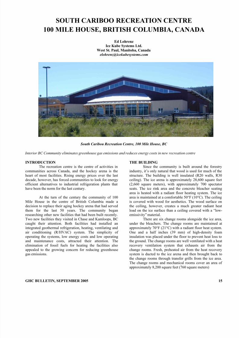
South Caribou Recreation Centre, 100 Mile House, BC
Interior BC Community eliminates greenhouse gas emissions and reduces energy costs in new recreation centre
INTRODUCTIONThe recreation centre is the centre of activities in
communities across Canada, and the hockey arena is the
heart of most facilities. Rising energy prices over the lastdecade, however, has forced communities to look for energyefficient alternatives to industrial refrigeration plants thathave been the norm for the last century.
At the turn of the century the community of 100Mile House in the centre of British Columbia made adecision to replace their aging hockey arena that had servedthem for the last 50 years. The community beganresearching other new facilities that had been built recently.Two new facilities they visited in Chase and Kamloops, BCcaught their attention. Both facilities had installed anintegrated geothermal refrigeration, heating, ventilating and
air conditioning (R/HVAC) system. The simplicity of operating the systems, low energy costs and low operatingand maintenance costs, attracted their attention. Theelimination of fossil fuels for heating the facilities alsoappealed to the growing concern for reducing greenhousegas emissions.
THE BUILDINGSince the community is built around the forestry
industry, it’s only natural that wood is used for much of the
structure. The building is well insulated (R20 walls, R30ceiling). The ice arena is approximately 28,600 square feet(2,660 square meters), with approximately 700 spectatorseats. The ice rink area and the concrete bleacher seatingarea is heated with a radiant floor heating system. The icearea is maintained at a comfortable 50°F (10°C). The ceilingis covered with wood for aesthetics. The wood surface onthe ceiling, however, creates a much greater radiant heatload on the ice surface than a ceiling covered with a “lowemissivity” material.
There are six change rooms alongside the ice areaunder the bleachers. The change rooms are maintained aapproximately 70°F (21°C) with a radiant floor heat system
One and a half inches (39 mm) of high-density foaminsulation was placed under the floor to prevent heat loss tothe ground. The change rooms are well ventilated with a hearecovery ventilation system that exhausts air from thechange rooms. Fresh, preheated air from the heat recoverysystem is ducted to the ice arena and then brought back tothe change rooms through transfer grills from the ice areaThe change rooms and mechanical rooms cover an area ofapproximately 8,200 square feet (760 square meters)
GHC BULLETIN, SEPTEMBER 2005 15

8/8/2019 September 2005 Geo-Heat Center Quarterly Bulletin
http://slidepdf.com/reader/full/september-2005-geo-heat-center-quarterly-bulletin 18/28
The lobby and viewing area overlooking the icerink is approximately 5,900 square feet (550 square meters).Adjacent to the lobby is an office area of approximately2,100 square feet (195 square meters). These areas areheated and cooled with several ground source heat pumpsconnected to the horizontal ground loop in the field behindthe building.
The refrigeration system of the existing curling rink adjacent to the new arena has been connected to the
geothermal system. The heating system of the lobby andlounge of the curling rink, however, has not been connected because of cost. There are plans to convert the heatingsystem in the near future.
THE REFRIGERATION SYSTEM
A hockey arena is typically the most expensive building to operate (energy cost and operating andmaintenance costs) in most small communities. Theelectrical costs associated with operating the compressorsand pumps of the refrigeration system are high. The majorityof the hockey arenas throughout Canada and much of theUnited States use ammonia as the primary refrigerant.
Ammonia is a very efficient refrigerant, but the largerefrigerant charge (1,000 to 1,200 pounds or 450 to 500 kg)requires constant monitoring and stringent safety procedures,including airlock entries to the refrigeration room, highcapacity ventilation systems, eyewash stations and oxygenmasks. Because of the potential danger, most jurisdictionsrequire highly trained operators and the system operating pressures must be monitored regularly.
Ammonia does not transport oil through the system.It collects in the evaporator, or chiller barrel, and must bedrained regularly, and treated as a hazardous waste product.Fresh oil must be added to the refrigerant system to ensurelubrication of the compressors. An average rink will drainand replace close to a barrel of oil annually, depending onhow heavily the rink is used. This adds approximately $500to $1,000 to the operating cost every year.
16 GHC BULLETIN, SEPTEMBER 2005
In this arena, eight large water to water heat pumpswere used in place of a traditional ice plant (Figure 1). Theheat pumps are designed to operate at source temperatures aslow as 0°F (-18°C). They are designed to produce water totemperatures as high as 125°F (51°C). Each of the heat pumps contains approximately 12 pounds (5.5 kg) of HFCrefrigerant R404A. The entire refrigeration system of eightunits contains approximately 10% of the refrigerant of atraditional refrigeration system, and it is contained in eightindependent units. Since this is a non-toxic refrigerant, thereis no need for the same level of safety considerations.
The eight separate heat pumps are piped as four pairs. Each pair of heat pumps is piped with two pumpsconnected to the chilled fluid side and two pumps to the hotfluid side. The chilled fluid can be circulated either to the icesurface piping, the thermal storage buffer or the earth loop to pick up heat. The heated fluid can be circulated either to the building heating system or the earth loop, based on thetemperatures in the building. This arrangement provides ahigh degree of redundancy
Figure 1. Eight low temperature water-to-water
heat pumps provide approximately 84 tons of refrigeration
at ice rink temperatures. The heat pumps reject heat either directly to a radiant floor heat system or to a horizontal
earth loop.
HUMIDITY AND TEMPERATURE CONTROL INTHE ICE AREA
Humidity control is important in an ice arena,especially if the ice surface will be used in warm weather.Condensation will form on the ice surface if the humidity istoo high, creating a significant load on the refrigerationequipment. Each pound of water that condenses on the icesurface absorbs over 1,100 Btu (0.33 kW) of energy. Steel atthe ceiling above the ice area radiates heat to the cold ice below it. Warm air at the ceiling will condense on the coldsteel, eventually causing rusting and structural damage. Itcan also collect and drip onto the ice, creating bumps on theice.
Figure 2. Dehumidification, air conditioning and heating are provided by a 20-ton heat pump in the ice area.
The unit can cool and reheat 40-50°F (5-10°C) air. It can
also cool or heat the arena by either rejecting or drawing
heat from the horizontal earth loop.
A heat pump designed specifically to providedehumidification is installed in the ice area (Figure 2). Theheat pump is designed to cool the air enough to condense themoisture from the air. Heat from the cooling process plus

8/8/2019 September 2005 Geo-Heat Center Quarterly Bulletin
http://slidepdf.com/reader/full/september-2005-geo-heat-center-quarterly-bulletin 19/28
compressor heat reheats the air to provide warmer, drier air.The heat pump is also connected to the earth loop through afluid to refrigerant heat exchanger. If the air temperature inthe ice area is satisfied, the heat can be rejected to the earthloop, and the unit is used to provide approximately 16 tons(56 kW) of air conditioning. It can also be used when thefacility is used for other activities, such as inline hockey or lacrosse during the summer.
The heat pump can also be used to extract heat
from the earth loop if additional heat is needed in the icerink area. It will provide approximately 200,000 to 250,000Btu/h (59 to 73 kW), depending on the earth looptemperature.
The spectator stands are heated with radiant floor heat piping embedded in the precast concrete bleachers(Figure 3). The warmed seats provide heat where it is mostneeded. If snow is tracked into the seats, or a drink is spilledin the stands, it is melted and evaporates quickly, reducingcleanup time and potential liability from someone slippingon wet concrete.
GHC BULLETIN, SEPTEMBER 2005 17
Figure 3. Much of the building, including the spectator seating, is heated with a radiant floor heat
system. The warm floor dries snow that is tracked from
outside into the building and reduces the opportunity for
mildew growth in the change rooms.
BUILDING HEATING AND COOLING
The ice surface and the Thermal Storage Buffer 1
are the primary heat source for the low temperature water towater heat pumps. Only when both the ice and the buffertemperatures are satisfied, and the building still needs heatdo the heat pumps extract heat from the earth loop. The building radiant floor heat system, the domestic hot wateand snow melt are the primary heat sink for the heat pumpsOnly when the building temperature is satisfied do the heat
pumps reject heat to the earth loop. Conventional grounsource heat pumps are connected to the earth loop to provideheating and air conditioning to the office areas (Figure 4).
A large site allowed the construction of a horizontaearth loop. The loop is a secondary heat source andsecondary heat sink for the main heat pump system, storingexcess heat that can’t be used. It is the primary heatsource/heat sink for the conventional forced air heat pumpsdomestic hot water heat pump and the dehumidification unit
Domestic hot water is preheated using a doublewall heat exchanger. When hot water is used in the buildingin showers or flooding the ice, make-up water is preheated toabout 75 to 85°F (25-30°C). A water to water heat pump
operating directly from the earth loop heats the water to120°F (50°C) (Figure 5).
Figure 5. A 10-ton water-to-water heat pump drawsheat from the earth loop to produce service hot water
(showers and ice flooding) at 120°F (50°C )
Heat removed from the ice is either used directly to provide space heating or domestic hot water, or is stored inthe earth loop. This type of facility is very cooling dominantand the earth loop becomes saturated with heat when the ice
1US Patent #6,170,278, Canadian Patent #2,273,760

8/8/2019 September 2005 Geo-Heat Center Quarterly Bulletin
http://slidepdf.com/reader/full/september-2005-geo-heat-center-quarterly-bulletin 20/28
Earth loop
Thermal storage
buffer
Low temperaturewater-water heat
pumps
Ice surface
Radiant floorheat
Chilled fluid side of
heat pumps
Preheat for makeup water
Snowmelt
Forced air heatpumps
DHWDehmidification/ heating/cooling
Fluidcooler
Figure 4.
is used in summer. A fluid cooler is used to prevent the earthloop from becoming overheated.
Air from the change rooms is continuouslyexhausted using a heat recovery ventilation (HRV) system.Fresh air from the HRV is introduced to the ice area. Air from the ice area is drawn into the change rooms throughintake grills from the ice area.
THERMAL STORAGEThe patented rink floor design provides thermal
cold storage directly beneath the ice surface. It providesseveral advantages over a conventional thin rink floor design:
• The large mass maintains a more consistent ice
temperature than a floor with little storage. This isespecially noticeable when the ice is being heavily usedand resurfaced often.
• The large mass of the floor is “sub-cooled” severaldegrees lower than the ice surface when the ice is not being used. This is the heat source used for the heat pumps to heat the building, while simultaneously providing a significant amount of refrigeration for the icewhen it is being heavily used.
• The sub-cooled buffer provides a significant portion of
the refrigeration during peak use. Both the refrigerationcapacity and the fluid circulation pumps required tomaintain the ice surface during peak use can be reduced.A conventional system would require a 20 to 30-hpcirculation pump for the ice surface and a 7.5 to 10-hpcirculation pump for the curling rink. Four 3-hpcirculation pumps provide the flow for both the icesurface and the curling rink. This reduces therefrigeration load created by friction losses in the rink
• surface pipe by 57 to 70% compared to a facility with aconventional thin floor.
• In the event of a power failure, the mass of the rink floor will maintain the ice for up to 3 days.
INTEGRATING SYSTEMS WITH AN EARTH LOOPThe integration of the entire system revolves
around the earth loop. The facility is built on a large site thatallows space for a horizontal earth loop (Figure 6). An areawas excavated behind for the installation of the earth loop.All heat pumps in the system are connected to the earth loop.The large water-to-water refrigeration units use the earthloop as a secondary heat source when the ice temperature issatisfied, and a secondary heat sink when the building
Hot fluid side of
heat pumps
18 GHC BULLETIN, SEPTEMBER 2005

8/8/2019 September 2005 Geo-Heat Center Quarterly Bulletin
http://slidepdf.com/reader/full/september-2005-geo-heat-center-quarterly-bulletin 21/28
temperature is satisfied. The forced air heat pumps in theoffice spaces, the water-to-water heat pump that produceshot water for showers and flooding the ice, and thedehumidification/heating/air conditioning unit are allconnected directly to the earth loop, and either pull heatfrom it, or reject heat into it as needed.
GHC BULLETIN, SEPTEMBER 2005 19
Figure 6. This photo shows the installation of the
horizontal earth loop at 100 Mile House, BC. 50,000 feet (15,200 m) of 1 inch (25 mm) pipe was installed to a depth
of 8 feet (2.4 m).
The primary benefit of integrating all the systemsinto a common earth loop takes advantage of the thermalstorage capacity of the earth. In a building such as the SouthCaribou Recreation Centre, the water-to-water heat pumpsused to make the ice either reject heat directly to the buildingradiant floor heat system, or to the earth loop. Since only a portion of the heat taken from the ice can be used in the building directly, even during a cold winter day, the earthloop is constantly being recharged by “waste heat” takenfrom the ice.
Heat pumps operate more efficiently and havehigher heating capacity when the source temperature ishigher. The heat pumps used for space heating and heatingwater typically operate with an earth loop of 55-70°F(13°C), and operate at a COP between 4.4 and 5.4.
In spring and fall when less heat is needed in the building, the earth loop temperature typically climbs to 80-90°F (27-32°C). To prevent the earth loop temperature fromclimbing even higher, an evaporative fluid cooler wasinstalled. During peak use of the ice the fluid cooler works
in parallel with the earth loop to reduce the load on the loop.More importantly, at night when the building is not beingused, the fluid from the earth loop is circulated through thefluid cooler to take advantage of cooler night timetemperatures to drop the loop temperature. This allows theloop to absorb heat more readily during peak use thefollowing day.
SYSTEM ECONOMICSThe cost of installing a geothermal system is
typically higher than the cost of installing a conventionasystem. This holds true with an integrated geothermal icerink application as well. The building qualified for aCommercial Building Incentive Program (CBIP) from Natural Resources Canada (NRCan) of $60,000. The capitacost of the integrated system is compared to the estimatedcost of installing a conventional refrigeration plant and
heating system in Table 1. As is often the case, thedifference in cost of the two systems is typically theapproximate cost of the installation of the earth loop.
The additional cost of installing the integratedsystem is offset by lower energy costs as well as loweroperating and maintenance costs. The energy costs of thefacility are shown in Figure 6, along with a comparison ofthe energy costs of a typical conventional system. Annualenergy cost savings are estimated at approximately $48,000annually.
Operating and maintenance costs for a conventionarefrigeration plant are typically much higher than the cost ofmaintaining other mechanical equipment. Ice rink owners
and operators typically budget approximately $14,000 to$17,000 annually for maintenance costs.
Table 1.
Integrated
System
Conventional
System*Refrigeration heat pumps,circulation pumps, rink floor
$575,000 $525,000
Horizontal loop $105,000 ---
Building heating, cooling,ventilation
$112,000 $96,000
Incentives (NRCan / CBIP) ($60,000) ---
Connecting Curling ArenaRefrigeration
$30,000 ---
Dehumidification $72,000 $110,000
Domestic hot water $34,000 $18,000
Total $868,000 $749,000* estimated cost of conventional system
Some of the costs of operating a conventionaammonia ice plant include:
• Oil to lubricate the compressor (ammonia vapor does nottransport oil from the evaporator (chiller barrel) back tothe compressor – it must be drained regularly andreplaced. Typical cost is approximately $500-1,200annually. The waste oil must then be disposed ofappropriately
• Compressor rebuilds. A conventional reciprocatingammonia compressor must be rebuilt after approximately6,000 to 8,000 hours of runtime, at a typical cost o$6,000 to $12,000. With the schedule of this facility, onecompressor would typically be rebuilt every year.
• In most jurisdictions it is required that an industrialrefrigeration plant must be monitored regularly

8/8/2019 September 2005 Geo-Heat Center Quarterly Bulletin
http://slidepdf.com/reader/full/september-2005-geo-heat-center-quarterly-bulletin 22/28
OVERALL SUMMARYTypically a rink operator must check the operating pressures and flows of the system 4-6 times per day (1.5-3 hours per day) This time is taken away from other needs in the facility.
Building Description:
• Occupancy: Hockey arena, curling arena, office space
• Location: 100 Mile House, BC• Special circumstances. The integrated geothermal system
is designed with a high level of system redundancy. Thedesign includes eight independent water-to-water heat pumps designed to operate with four sets of circulation pumps. If a heat pump or circulation pump fails, the
other heat pumps and circulation pumps simply carry onto maintain the ice. If the single circulation pump, or oneof two or three large compressors fails, the system must be repaired immediately, often at emergency servicerates.
• Gross Floor Area: 56,400 square feet (5,241 squaremeters)
o Arena: 28,600 square feet (2,498 square meters)o Offices, change rooms, lobby: 15,400 square feet
(1,430 square meters)o Curling Arena: 9,000 square feet (836 square
meters)o Curling Lobby & Lounge: 3,600 square feet (335
square meters)
• Constructiono Hockey Arena: new construction, well insulatedEnergy Cost Comparison
$0
$10,000
$20,000
$30,000
$40,000
$50,000
$60,000
$70,000
$80,000
$90,000
$100,000
$110,000
$120,000
Conv entional Syste m Inte grate d Geothe rmal
E n e r g y
C o s t
Other Electric
Air Conditioning
Hot Water
Heating
Dehumidification
Pumps
Refrigeration
o Curling Arena: retrofit
• Completion Date: 2002
• Heating Degree Days (below 64.4°F / 18°C): 9,076 /5,042
System Description:
• Refrigeration heat pumps (hockey and curlingcombined): 88 tons (310 kW)
• Hockey Arena climate controlo Humidity control: 15 tons (52.8 kW)o Cooling: 15 tons (52.8 kW)o Heating: 230,000 Btu/h (68.6 kW)
• Heating / cooling (offices, change rooms, lobby etc.): 24tons (84 kW)
• Fluid: Methanol 30%, & water Figure 6. The actual energy cost of the facility in
2004 was slightly over $60,000. Energy consumption was
1,195,000 kWh, with a peak electrical demand of 257 kW.The total energy consumption of a comparable rink with a
conventional refrigeration plant and gas fired heating
system is estimated at approximately $107,000 annually.
Heating, service hot water and dehumidification would typically be done with gas equipment. Gas costs for a
conventional system in this building are estimated at
approximately $40,000 annually.
• Circulation pumpso Refrigeration heat pumps (Hockey and Curling
Arenas) 4 3-hp circulation pumps building heating
system / earth loop 4 3-hp circulation pumps for ice floor
circulation / earth loopo Heating / cooling heat pumps
1 3-hp circulation pump
• Earth Loop: Horizontal earth loop, buried to 8 feet (2.4meters), 50 circuits of 1” (25 mm) HDPE SDR11 pipe,1,000 feet (300 m) length
The water-to-water heat pumps do not requirecompressor rebuilds. Oil does not have to be drained fromthe system regularly. The size of the compressors of thewater-to-water heat pumps and built in redundancy of thesystem eliminates the much of the daily operating cost of thesystem and reduces the cost of service. Similar ice rink facilities report operating and maintenance costs of $4,000 to$5,000 annually after several years of operation.
Special Features:
• Thermal storage buffer floor (patented) design tominimize peak refrigeration demand and maintainconstant ice temperature
• Optimized rink pipe layout to reduce pumping power requirementsThe simple payback of the system installed in 100
Mile House is estimated at approximately two years if the NRCan / CBIP incentive is included, and approximatelythree years if no incentive is considered.
• Earth loop to store excess heat and provide additionalheat as needed
20 GHC BULLETIN, SEPTEMBER 2005

8/8/2019 September 2005 Geo-Heat Center Quarterly Bulletin
http://slidepdf.com/reader/full/september-2005-geo-heat-center-quarterly-bulletin 23/28
SUNDOWN M RANCH
YAKIMA, WASHINGTON
Dr. R. Gordon Bloomquist, Ph.D.,
Washington State University Energy Program
Photo credit: http://www.sundown.org /
BUILDING CHARACTERISTICS
The Sundown M Ranch, located just northwest of Yakima, Washington, is a drug and alcohol rehabilitation
center for both youths and adults. The 134,880 ft
2
(12,531m2) complex was built in several phases beginning in 1985with the adult facility totaling 77,300 ft2 (7,181 m2),followed by a family annex of 20,650 ft2 (1,918 m2) in 1990,a 39,730 ft2 (3,961 m2) youth facility in 1992, and the 7,200ft2 (669 m2) administration building in 1995. The facilityalso provides laundry and food services for the patients. The buildings are stick-built wood frame, low-rise residentialstyle. The buildings are well insulated and use primarilyfluorescent lighting.
The residences are occupied 24 hours per day,while other facilities are normally occupied during normaloffice hours except for the gym that has an intermittentoccupation pattern.
GEOTHERMAL HEAT PUMP SYSTEM
CHARACTERISTICS
A process schematic is shown in Figure 1.Geothermal Source Description
The complex is served by two production wells atca 57ºF (13.9oC) and one injection well. The main well isapproximately 200 ft (61 m) deep, and provides 360 gpm(22.7 L/s) via a 15-hp (11 kW) submersible pump. The
second well is 187 ft (57 m) deep and supplies 260 gpm(16.4 L/s). It has a 15-hp (11 kW) submersible pump. Afte passing through the heat pump, the water is injected or used
for irrigation during the summer months. The well pumpare run 24-hours per day at constant speed. Flow iscontrolled through the use of throttling valves. There arealso two domestic water wells on the property. In additionto use for heating and cooling and domestic purposes, thewells together can supply a maximum of 1,100 gpm (69.4L/s) for fire protection.
Heating, Ventilation, and Air Conditioning (HVAC)
System Description
The various facilities are served by a combinationof heat pumps and heat pump unit ventilators (Figure 2).Water is circulated in an open loop to each building.Circulating pumps serves to boost the flow through thevarious buildings. A total of 297 heat pumps supply thecomplex comprised of 257 1-ton (3.5 kW) heat pump unitventilators, 12 3-ton (10.5 kW) units, and 28 5-ton (17.6kW) units for a total of 433 tons (1,523 kW). In additionthere are four 5-ton (17.6 kW) water-to-water heat pumps inthe adult building for hot water and two 5-ton (17.6 kW)units with back-up electric water heaters serving the youthfacility (Figure 3). There is a 1,000 gallon (3785 L) howater storage tank in the adult facility
GHC BULLETIN, SEPTEMBER 2005 21

8/8/2019 September 2005 Geo-Heat Center Quarterly Bulletin
http://slidepdf.com/reader/full/september-2005-geo-heat-center-quarterly-bulletin 24/28
ProductionWells
InjectionWell
To HeatPumps inBuildings
From HeatPumps inBuildings
To Irrigationin Summer
360 gpm(22.7 L/s)
260 gpm(16.4 L/s)
200 ft(61 m)
187 ft(57 m)
Figure 1. Process schematic of Sundown M Ranch.
SELECTION OF THE GEOTHERMAL HEAT PUMP
SYSTEM
22 GHC BULLETIN, SEPTEMBER 2005
Figure 2. Console heat pump.
The geothermal heat pump system was selectedupon the recommendation of the serving utility, PacificPower and Light; the availability of adequate supplies of reliable warm water; a desire for energy efficiency; and aguaranteed reduction in electrical rates by the serving utilityif the heat pump system was installed. They were also veryinterested in having the ability to provide individual roomcontrol.
OPERATING HISTORY
The system has been built-out over 14 years, withadditional buildings added every few years. The system has performed as expected, and has experienced few operating problems. The fact that for each subsequent phase of the build-out, the decision has been to continue with geothermalheat pumps is a good indication of the system’s excellentoperational performance.
OPERATION AND MAINTENANCE ISSUES
The system is operated and maintained by in-housestaff. Since the well pumps are not equipped with variablespeed drives, the pumps must be operated 24 hours per day.
Flow is controlled by use of a throttling valve. In summer use, the water coming out of the loop is used for irrigation purposes and in certain cases this can reduce the water available to the loop to the extent that the system doesexperience some high head problems on the heat pumps.
Each heat pump has a valve that opens or closesdepending on whether the heat pump is on. The heat pumpsand unit ventilation have outdoor air access and arecontrolled by thermostats.
Figure 3. Water to water heat pump.

8/8/2019 September 2005 Geo-Heat Center Quarterly Bulletin
http://slidepdf.com/reader/full/september-2005-geo-heat-center-quarterly-bulletin 25/28
GHC BULLETIN, SEPTEMBER 2005 23
The one on-going operational problem has beenassociate
nce going into operation in 1985, compressors
have bee
all heat
ng $0.12 to$0.15 ft
STEM ECONOMICS
sed build-out of the system over
the past
TISFACTION WITH THE SYSTEM
omplex seem to be very
d with the injection well. The well tends to plug upand will not accept the return flow. This in turn causes a pressure build up in the injection system and often results in broken PVC pipes. Because of this, the well is now cleanedevery six months by reversing the flow. Chlorine is alsoadded to kill organic material that is the source of the plugging.
Si
n replaced on 11 unit ventilators and 3 heat pumps.Three fan motors have also been replaced. Once a monththey change filters and back flush the coils on each heat pump, and check the screens going into each unit ventilator.
Every six months, they do a thorough inspection of pumps and unit ventilators including coils, fans and
motors, water flow, and operation. Once a year, they do athorough cleaning of the heat pumps and coils.
Annual maintenance costs are runni2 ($1.29-$1.61/m2).
SY
Because of the pha
14 years, there are no records available in relation tooverall system costs. The owners, however, feel that thesystem has been very economic to operate, and the annualmaintenance costs of $0.12 to $0.15/ft2 ($1.29 to $1.61/m2)is very acceptable.
SA
The owners and operators of the csatisfied with the system. It has been economic to
operate, requires only normal maintenance and a very fewunits have required repair or replacement. Operational staff indicated that there was less than 100 percent satisfaction on
the part of some patients due to the fact that the units do no provide instantaneous heat. They get on the average of onecomplaint per month.
OVERALL SUMMARY
Building Description:
Location: Yakima, WAOccupancy: Drug rehabilitationGross Floor Area: 134,880 ft2 (12,531 m2), multiple
buildingsType of Construction: NewCompletion Date: 1985-1995
July Avg. High Temp.: 87oF (30.6oC) Jan Avg. Low Temp.: 21oF (-6.1oC) Annual Heating Degree Days: 6012oF-day (3340oC-day) Annual Cooling Degree Days: 465oF-day (258oC-day)Interior System:
Total Installed Heat Pump Capacity: 433 tons (1523 kW) No. of Heat Pump Units: 297 water-to-air, 5 water-to-water Heat Pump Capacities: 1, 3 and 8.5 ton (3.5, 10.5 and 17.5kW) water-to-air; 5 tons (17.5 kW) water-to-water Ground-Source System:
Type: Open loop Mean Groundwater Temp.: 57 oF (13.9oC) Configuration: 2 production wells, 1 injection wellWell Depths: 187-200 ft (57-61 m)
Pumping Rates: 620 gpm total (39 L/s)Economic Analysis:
Installed Geothermal HVAC Capital Cost: unavailable
Total Annual Building Energy Use:20.07 kWh/ft2 (216 kWh/m2)
Annual Maintenance Costs:$0.12-$0.15/ft2 ($1.29-$1.61/m2)

8/8/2019 September 2005 Geo-Heat Center Quarterly Bulletin
http://slidepdf.com/reader/full/september-2005-geo-heat-center-quarterly-bulletin 26/28
INN OF THE SEVENTH MOUNTAIN
BEND, OREGON
Dr. R. Gordon Bloomquist, Ph.D.,
Washington State University Energy Program
BUILDING CHARACTERISTICS
The Inn of the Seventh Mountain is a hotel/condominiumcomplex located approximately seven miles (11 km) fromBend, Oregon, on the road to the Mt. Batchelor ski area,about 175 miles (280 km) south of Portland. The Inn was
first built in 1972, and consists of 22 individual condo buildings containing 350 units for a total of 248,800 ft2 (23,115 m2). The complex contains restaurants, aconference center, ice rink, spa, and other amenitiescommon to a first-class destination resort. The complex isof wood construction. Heat was originally provided withresistance electric ceiling heat. Most of the lodging units arethree stories. The buildings were built to meet the energycodes of the early 1970s, and according to operation staff under insulated. Windows are all double-paned.
GEOTHERMAL HEAT PUMP SYSTEM
CHARACTERISTICS
A process schematic is shown in Figure 1.Geothermal Source Description
The geothermal source is provided by one welllocated close to the central heat pump plant. Water flow is1,150 gpm (72.5 L/s) at 50ºF (10oC). The production well is400 ft (122 m) deep. Pumping is provided by a 225-hp (168kW) variable speed pump. After passing through heatexchangers (Figure 2), the water is disposed of through aninjection well located near the edge of the property.
Heating, Ventilation, and Air Condition (HVAC) System
Description
The central heat pump system consists of two 250-ton (879-kW) screw compressor heat pump/chillers (Figure3). Originally, when the retrofit to heat pumps took place in
1992, one 300-ton (1053 kW) centrifugal unit was installed but, because it was oversized, it continued to surge andwould not stay on-line. The two 250-ton (879-kW) screwcompressors have proven to be much more satisfactory. Theheat pump/chillers are separated from the geothermal sourcethrough the use of two plate and frame heat exchangers.Distribution of hot [ca 115ºF (46oC)] or chilled [50ºF(10oC)] water is via a four-pipe distribution system. Thedistribution system is centrally controlled for optimumtemperature balance and energy use. The four-pipe systemsupplies fan coil units distributed throughout the condo unitsand other buildings. Hot water from the distribution systemalso preheats the domestic hot water supply to buildings.The swimming pool, spa tubs, and the bath house are also
heated by the heating loop. The chilled water loop serves asthe condenser water for the ice ring.
SELECTION OF THE GEOTHERMAL HEAT PUMP
SYSTEM
24 GHC BULLETIN, SEPTEMBER 2005
and gas absorption cooling. The servicing electric utility,
By the late 1980s, the 1972 complex was beginningto experience problems with the ceiling electric resistanceheating units, and there was an increasing need to be able to provide air conditioning during the summer months. Theowners first looked at replacing the system with gas heating

8/8/2019 September 2005 Geo-Heat Center Quarterly Bulletin
http://slidepdf.com/reader/full/september-2005-geo-heat-center-quarterly-bulletin 27/28
however, recommended the geothermal heat pump option asa means to meet both heating and air conditioningrequirements and provided incentives to the owners. Theconversion was made at an investment of ca $3 million. Theconversion project resulted in a 49 percent savings inmetered energy, but only a 3 percent savings in energycosts. However, it must be remembered that the system nowalso provides air conditioning that was not provided by thesystem replacement.
GHC BULLETIN, SEPTEMBER 2005 25
Figure 1. The process schematic for the Inn of the
Figure Photograph of one plate and frame heat
OPERATING HISTORY
rsion from electric ceilingresistanc
igure 3. Photograph of one of the water-to-water hea
is that there isno centra
INTENANCE
emely well since
SYSTEM ECONOMICS
trofit to geothermal heat pumpsresulted
Seventh Mountain.
2.
exchanger at the Inn of the Seventh Mountain.
When the convee units to a central geothermal heat pump system
was made, the decision was made to go with one 300-ton(1053 kW) centrifugal heat pump/chiller. This, however,
proved to be a poor choice, and during light loads, the uniwas considerably oversized and continued to surge andwould not stay on-line. After only a short period of time, iwas decided to replace the 300-ton (1053 kW) centrifugaunit with two 250-ton (879 kW) screw compressor units.These units also suffered some initial problems due to faultythrust bearings, and both motor assemblies had to bereplaced within the first year. However, after these initiadesign and equipment problems, the system has operated as
expected and with minimal operational or maintenance problems.
F
pumps at the Inn of the Seventh Mountain.
only short coming of the systemThel control over thermostats in individual condo units
thus when units are not occupied, there is no way to monitoror control temperature levels. This has resulted in manyunoccupied units being heated or cooled needlessly and, of
course, with a substantial waste of energy and with asignificant cost penalty.
PERATION AND MAO
The system has operated extr initial problems associated with the centrifugal heat pump/chiller and motor thrust bearings were solved. Ineither case was the problem a result of or caused by thegeothermal source. Maintenance and operation are bothtaken care of by an experienced and very competent in-house staff.
The $3 million rein a 49 percent reduction in metered electricaenergy consumption, and a 3 percent reduction in overalenergy cost, while at the same time providing airconditioning. The total energy consumption for the facilityis 24.47 kWh/ft2/yr (263.4 kWh/m2/yr), while the heat pump plant uses 10.14 kWh/ft2/yr (109.1 kWh/m2/yr). Annuamaintenance cost for the past several years have averagedapproximately $0.18/ft2 ($1.94/m2). The annual energyusage as well as the maintenance cost is somewhat of anover estimate, as the system also provides heating to two
ProductionWells
InjectionWell
To B d ings(Fo ipe Syste mto Fan Coil Units)
From Buildingsuilur P
HeatPump
HeatPump
Water-towater heat pumps250 tons (879 kW) each
Heat Exchanger Heat Exchanger
1,150 gpm
(72.5 L/s)
400 ft(122 m)

8/8/2019 September 2005 Geo-Heat Center Quarterly Bulletin
http://slidepdf.com/reader/full/september-2005-geo-heat-center-quarterly-bulletin 28/28
swimming pools and the spa pools, and the chilled water.loop serves as the condenser water for the ice ring.
SATISFACTION WITH THE GEOTHERMAL HEAT
PUMP S STEM
e system has operated and the lack of mainten
The author wishes to thank Jon Menzic, the director e Seventh Mountain and Clark
Satrae o
MMARY
Building escription:
ominium resort8,800 ft2 (23,115 m2), 22 buildings
1972, heat pump retrofit in
vg. High Temp.: 81.7 F (27.2 C)
F-day (2494oC-day)
at Pump Capacity: 500 tons (1758 kW)
p.: 50oF (10oC) tion well
2.5 L/s)
Capital Cost:
Total An Energy Use:/m2)
Total An
it of cooling Annual M
EAT CEOregon Institute of Technology
01
Nonprofit OrganizationU.S. Postage
Y
Operation and maintenance staff are both extremelyhappy with how th
ance problems that have occurred. The systemseems to provide a high level of comfort to guests. It would
appear that even greater energy and cost savings would be possible if the system were set up so that individual unitscould be monitored and thermostats adjusted when the unitswere unoccupied for any extended length of time.
ACKNOWLEDGEMENT
of facilities for the Inn of thf Pacific Power and Light for their assistance in
obtaining data.
OVERALL SU
D
Location: Bend, OR Occupancy: Hotel/condGross Floor Area: 24Type of Construction: Retrofit
Completion Date: Buildings in1992
July A o o
Jan Avg. Low Temp.: 23oF (-5.0oC) Annual Heating Degree Days: 4490o
Annual Cooling Degree Days: 12oF-day (7oC-day) Interior System:
Total Installed He
No. of Heat Pump Units: 2 water-to-water
Heat Pump Capacities: 250 tons ( 879 kW)Ground-Source System:
Type: Open loop
Mean Groundwater TemConfiguration: 1 production well, 1 injecWell Depths: 400 ft (122 m)
Pumping Rates: 1,150 gpm (7 Economic Analysis:
Installed Geothermal HVAC
$3 millionnual HVAC 10.14 kWh/ft2 (109.1 kWhnual HVAC Energy Savings:
49% plus the additional benef aintenance Costs:$0.18/ft2 ($1.94/m2)
GEO-H NTER
Klamath Falls, Oregon 97601-88
PAIDKlamath Falls, OR 97601
45Permit No.