Embed Size (px)
Citation preview

GEO-HEAT CENTER Quarterly Bulletin
Vol. 26, No. 2
ISSN 0276-1084
OREGON INSTITUTE OF TECHNOLOGY -KLAMATH FALLS, OREGON 97601-8801PHONE NO. (541) 885-1750
Combined Geothermal Heat & Power Plants
JUNE 2005
Vol. 26, No. 2 June 2005
GEO-HEAT CENTER QUARTERLY BULLETINISSN 0276-1084
A Quarterly Progress and Development Reporton the Direct Utilization of Geothermal Resources
CONTENTS Page
Combined Geothermal Heat 1and Power Plants
Integrating Small Power Plant Into 2Direct-Use Projects Dr. R. Gordon Bloomquist.
Husavik Energy - Multiple Use of 7Geothermal Energy Hreinn Hjartarson and Runolfur Maack
Sudurnes Regional Heating 14Corporation, Svarsengi, Iceland Geir Thorolfsson
Hitaveita Reykjavikur and the 19Nesjavellir Geothermal Co-Generation Power Plant Edited by John W. Lund
Hot Artesian Water Powers an 25Outback Town in Australia Prame N. Chopa.
Bad Blumau (Styria, Austria) - The 27 Success Story of Combined Use of Geothermal Energy Johann Goldbrunner
Combined Heat and Power Plant, 31Neustadt-Glewe, Germany Compiled by John W. Lund
Cover: Modified schematic of the Neustadt-Glewe, Germany, combined heat andpower plant (courtesy of GeotermischeVereinigun).
PUBLISHED BY
GEO-HEAT CENTEROregon Institute of Technology
3201 Campus DriveKlamath Falls, OR 97601
Phone: 541-885-1750Email: [email protected]
All articles for the Bulletin are solicited. If you wish tocontribute a paper, please contact the editor at the aboveaddress.
EDITOR
John W. LundTypesetting/Layout - Donna GibsonGraphics - Tonya “Toni” Boyd
WEBSITE http://geoheat.oit.edu
FUNDING
The bulletin is provided compliments of the Geo-HeatCenter. This material was prepared with the support ofthe U.S. Department of Energy (DOE Grant No. DE-FG03-01SF22362). However, any opinions, findings,conclusions, or recommendations expressed herein arethose of the author(s) and do not necessarily reflect theview of USDOE.
SUBSCRIPTIONS
The bulletin is mailed free of charge. Please send yourname and address to the Geo-Heatr Center for addition tothe mailing list.
If you wish to change your bulletin subscription, pleasecomplete the form below and return it to the Center.
Name________________________________________
Address______________________________________
______________________ Zip ___________________
COMBINED GEOTHERMAL HEATAND POWER PLANTS
Combined heat and power (CHP) plants are not anew use of energy, whether it be from conventional fossilfuels or geothermal. However, what has been happeningrecently in the geothermal arena is the use of low-temperatureresources (down to 98oC or 208oF) in combination with binaryor Organic Rankine Cycle (ORC) power units. Two installa-tions, one in Australia at Birdsville and one in Germany atNeustadt-Glewe, both reported in this issue of the QuarterlyBulletin, are using temperatures this low–the lowest currentlyoperating in the World!! However, there was an even lowertemperature use at Paratunka, Kamchatka, Russia; a binarypower plant using 81oC or 178oF producing 680 kWe and thewastewater used for heating the soil and water plants ingreenhouse, was in operation for a number of years in the late1960s and early 1970s.
This issue of the Quarterly Bulletin reports on hightemperature CHP installations in Iceland at Svartsengi andNesjavellir, and low-temperature installations in Iceland atHusavik, in Austria at Bad Blumau and the two mentionedabove in Australia and Germany. We took some liberty ininterpreting the CHP description, as the Birdsville installation,after producing electric energy uses the spent fluid fordomestic drinking water and for stock watering, and not forspace heating. We also know of CHP plants elsewhere inworld, described below.
However, first a little background. Why CHP?? Themain reason is that it makes more efficient use of the resourceby cascading the temperature (energy use), which in turnimproves the economics of the entire system. Low-temperature power generation alone is often not economicalbelow 150oC or 300oF as the net plant efficiency for ORCunits varies from 12% down to 7% (to 90oC or 194oF) (see apaper by Kevin Rafferty on Geothermal Power Generation onthe GHC website). One of the exceptions in the U.S. is atWineagle in northern California using 110oC or 230oFresource; however, this plant has no pumping cost anddisposes the spent fluid to the surface. There are several otherstand-alone ORC plants in the United States and elsewhere inthe world using low-to- moderate temperature geothermalresources (GHC Quarterly Bulletin, Vol. 20/2–March 1999).Many CHP plants, especially those using a low-temperatureresource, started as just a district heating project. The electricpower plant was later added, and became economical, as thewell and pumping systems were already in place. All thepower plant designers/ operators did was take sometemperature off the top, yet still providing enough temperature(energy) for the district heating system.
This cascaded use of geothermal energy in the formof CHP plants has been described in previous issues of theGHC Quarterly Bulletin, and thus, is not reproduced here, butis summarized below:
GHC BULLETIN, JUNE 2005
• Empire Energy in northwest Nevada, where the heat iscascaded to an onion/garlic dehydration plant and alsoplanned to be used for fish raising (see article by R. G.Bloomquist – “Empire Energy, LLC – A Case Study,” Vol.25/2, 2004).
• Altheim, Austria using 106oC or 223oF to operate anapproximately 500-kWe plant and providing heat to about650 consumers (see article by G. Pernecker and S.Uhlug–“Low-Enthalpy Power Generation with ORC-Turbogenerator–The Altheim Project, Upper Austria,” Vol.23/1, 2002).
• Suginoi Hotel, Beppu, Japan using 143oC or 289oF tooperate a 3-MWe condensing steam turbine and supplyingthe waste fluid to the hotel for space heating and baths.(see article by K. Kudo–“3,000 kW Suginoi HotelGeothermal Power Plant,” Vol. 17/2, 1996).
• Hatchobaru, Japan using 106oC or 223oF from thecondenser of the Hatchobaru power plant (2x55 MWe) forheating a demonstration greenhouse (see article by P.Lienau–“Geothermal Greenhouses in Kyushu, Japan,” Vol.17/2, 1996).
• Fang, Thailand using 116oC or 241oF to operate a 300-kWe ORC plant and the waste water then cascaded for useat a refrigeration (cold storage) plant, crop drying and a spa(see article by J. Lund and T. Boyd–“Small GeothermalPower Project Examples,” Vol. 20/2, 1999).
• Mt. Amiata, Italy using 184oC or 363oF steam to operatea 15-MWe condensing plant and the waste water piped to22 hectars (54 acres) of greenhouses and for a vegetabledehydration plant (see article by J. Lund–“Cascading ofGeothermal Energy in Italy,” Vol. 10/1, 1987).
• Palinpinon, Philippines using 160oC or 320oF fluid fromthe Palinpinon I steam gathering system, where 192 MWeare produced. The steam is passed through a shell-and-tube heat exchanger and the 154oC or 309oF fluid is usedin a drying plant producing copra (dried coconut meat) (seearticle by S. Chua and G. Abito–“Status of Non-ElectricUse of Geothermal Energy in the Southern NegrosGeothermal Field in the Philippines,” Vol. 15/4, 1994).
• New Zealand: at Broadlands, the Ohaaki power plantprovides steam to dry alfalfa (Lucerne); at Wairakei, thepower plant provides waste heat for 19 giant Malyasianfreshwater prawns ponds; and at Taupo, the power plantoperated by Mercury Geotherm provides steam to agreenhouse, where orchids are raised (see GHC Bulletin,Vol. 19/3, 1998 for details).
• Los Azufres, Mexico using condensate from the steampipeline feeding a 50-MWe unit at about 170oC or 338oFfor use in an experimental lumber drying kiln, agreenhouse and fruit dehydrator (see article by J.Lund–“Design of a Small Fruit Drier Using GeothermalEnergy,” Vol. 17/1, 1996) and the companion article in theGRC Transactions, Vol. 19 (1995) by E. Sanchez-Velascoand E. Casimiro-Espinoza–“Direct Use of the GeothermalEnergy at Los Azufres Geothermal Field, Mexico” – pp.413-415.
The Editor
1

INTEGRATING SMALL POWER PLANTSINTO DIRECT-USE PROJECTS
Dr. R. Gordon Bloomquist, Ph.D.,Washington State University Energy Program
INTRODUCTIONAlthough generation of power from geothermal
energy with small “wellhead generators” (i.e., units <5MWe)is not new, the past few years have seen an increased interest,application and research into this technology (see GHCBulletin, Vol. 20, No. 2, 1999). As a result, there has been aconsiderable amount of work done on various working fluidsincluding various Freon, organic fluids (e.g., propane,isobutene, etc.), ammonia, and interest and research into low-temperature flash is also on the rise.
Some existing units have now seen over 20 years ofoperation and although most earlier units were put online asstand alone plants, or as the first step in demonstrating theviability of a field prior to build out, recent work has beendirected toward the development of combined heat and powerprojects that couple power production with direct-useapplications. Recent projects in Austria, including the RognerHotel and Spa Eco-Resort in Bluman (Figure 1) and thegeothermal district heating project in Altheim (Schochet andLegmann, 2002; Gaia 2002) are excellent examples ofintegrated projects designed to both provide power and supplyspace heating (see article in this Bulletin).
Figure 1. Series 250 ORMAT Energy ConverterPower Unit at Bad Blumau (Schochet &Legmann, 2002).
One of the most interesting recent developments inthe use of small wellhead-type generation is the coupling ofsuch systems to agribusiness (e.g., agriculture crop dehy-dration, alcohol distillation, greenhouses and aquaculture).
HISTORYThe advent of small power plants dates to the very
beginning of geothermal power production. The first plant
2
dates back to 1904 when Prince Piero Ginori Conti first usedgeothermal energy to power 10-kWe reciprocating engine todrive a small generator in order to provide lighting to his boricacid factory in Larderello, Italy (Lund, 2004).
The first commercially produced geothermal powerwas also generated at Larderello; when in 1914, a 250-kWeunit began providing power to the cities of Volterra andPomaronce.
In the early-1900s, the first small geothermal powerplant in the United States went online at The Geysers innorthern California. This 35-kWe unit provided power to thelocal resort, and a few, if any, could imagine at the time thatThe Geysers geothermal field would someday be the largestproducer of geothermal power in the world.
In 1967, an experimental binary power plant wascommissioned at Paratunka, Kamchatka, Russia (Lund andBoyd, 1999). This small 680-kWe power plant used 81oC(178oF) geothermal water and although it is considered to beone of the earliest binary power plants, it is interesting to notethat the first commercial geothermal power plant at Larderellowere also, in fact, binary-type plants. At Larderello, thegeothermal steam was used to evaporate clean water to powersteam turbines; thus, avoiding the corrosion effects related tothe use of the geothermal steam directly (DiPippo, 1999).
By the early-to-mid 1980s, small binary plants hadbeen demonstrated to be economically viable in a number oflocations and by the mid-1990s, commercial plants werelocated throughout the western U.S., and throughout much ofthe world. Small flash plants have also proved theircommercial viability and can be found in such diversecountries as Iceland, Mexico, Japan, Portugal (Azores) andEthiopia to name but a few (Lund and Boyd, 1999).
TECHNOLOGIESThe vast majority of small geothermal power plants
are either binary or flash; although, some are a hybrid of both,and even dry steam has been used in at least one application.Both flash steam and binary technologies have their ownproponents, and each has its own set of advantages anddisadvantages.
Flash Steam PlantsIn a flash steam plant (either single or double flash),
the two-phase flow from the well is directed to a steamseparator; where, the steam is separated from the water phaseand directed to the inlet to the turbine. The water phase iseither used for heat input to a binary system in a direct-useapplication, or injected directly back into the reservoir (Figure2).
GHC BULLETIN, JUNE 2005

CSVT/G
WPPW IW
C
CT
CWP
CP
SE/CSP
CS
WV
MR
BCV
S
CSVE
T/G
CSR
P
PW FFIW
PH
CT
CWP
M
IP CP
SH
E
CSVT/G
C
R
SR
PPH
IPPW
CP
CT
CWPM
FF
IW
Figure 2. Simplified flow diagram for a single-flashgeothermal power plant (DiPippo, 1999).
The steam, after passing through the turbine, exitsinto the condenser; where, it is cooled via water from thecooling tower. Historically, flash has been employed whereresource temperatures are in excess of approximately 150oC(300OF); however, studies completed by Barber Nichols Inc.of Arvada, Colorado (Forsha, 1994) would seem to indicatethat flash technology could be employed at temperatures aslow as 120oC (250oC) or less, and at a cost significantly lowerthan that of a similarly sized binary plant. Cost savings areattributable to cost differences in the heat addition and heatrejection systems of the two competing technologies.Examples of small flash plants can be found in, for example,Japan and Guadalupe.
In Japan, a small flash facility was installed at theKirishima International Hotel in Beppu, Kyusha in 1983. The100-kWe non-condensing unit operates on the output of twoproduction wells and has an inlet temperature of 127oC(261oF) at 2.45 bar (35.5 psi). Electricity is used for base loadin the hotel and provides 30-60% of the load depending uponseason and time of day. Hot water from the separator is usedfor outdoor bathing, space heating and cooling, domestic hotwater heating of a sauna bath , and for two indoor baths (Lundand Boyd, 1999).
On the Island of Guadalupe, the Bouillantegeothermal flash condensing power plant was put online in1986 with the plant being modernized and severalimprovements made in 1995 and 1996 (Correia, et al., 1998).Improvements included installation of three automatedcontrollers to monitor all plant activity and manageoperations. The plant is a double-flash plant based on ageothermal resource of approximately 200oC (392oF). Steampressure from the two separators are six and one bar (87 and15 psi), respectively. Cooling is through the use of seawaterin a direct-contact heat exchanger.
Binary PlantsIn a binary plant (Figure 3), the thermal energy of the
geothermal fluid is transferred to a secondary working fluidvia a heat exchanger to use in a conventional Rankine Cycle,or alternatively Kalina Cycle (Figure 4). The vaporizedworking fluid (e.g., isopentane, propane, Freon or ammonia)drives the turbine before being condensed and returned to theheat exchanger in a closed loop. Cooling is generallyprovided through the use of air coolers; although, some work
GHC BULLETIN, JUNE 2005
on evaporatively enhanced air cooling is ongoing (Sullivan,2001) and could result in efficiency improvements of 5% ormore during summer periods.
Figure 3. Simplified flow diagram for a basic binarygeothermal power plant (DiPippo, 1999).
Figure 4. Simplified flow diagram for a Kalinabinary geothermal power plant (DiPippo,1999).
Examples of small binary plants are found, forexample, in the United States and Austria. The Wineagle andAmedee power plants are located near the shore of HoneyLake in northern California. Th e Wineagle power plant wentonline in 1985, and consists of two binary units of total grossoutput of 750-kWe and a net output of 600-kWe. TheAmedee plant is composed of two units of one -MWe each andhas a net output of 1.5 MWe. Resource temperatures arerelatively low, 110oC (230oF) at Wineagle and 104oC (219oF)at the Amedee plant, and flow rates are 63 L/s (1000 gpm) and202 L/s (3200 gpm), respectively. The plants were designedto operate on Freon 114, but since then, the Wineagle planthas been converted to operate on isobutene (Nichols, 2003).Both plants have operated with an availability of over 90%and a capacity factor that has at times exceeded 100% of nameplate. The plants are fully automated and are designed tooperate unmanned and to go through a self-start procedure iftripped off line due to a transmission line failure. The plantscan be monitored and started remotely if required.
3

Brine in
Brine out
BoilerHE-3
bp bp RecuperatorHE-2
CondenserHE-1
Cooling Water Out
Cooling Water In
SUPERHEATERGENERATORGEAR POWER
MODULE
4
3
FLASHSEPARATOR
TURBINE
GEO FLUID FROM WELL
GEO FLUID TO NURSERY
1
2
6
5
7
WATERPUMP
COOLINGTOWER
DIRECT CONTACTCONDENSER
HOT WELL
WATERPUMP
The Altheim, Austria binary plant is a 1-MWe netoutput facility designed to operate on 86 L/s (1360 gpm) of106oC (223oF) geothermal water. The plant is water cooled.The plant uses a special high molecular mass organiccompound as the working fluid. According to Gaia (2002),the working fluid is non-flammable, non-corrosive and has noozone depletion activity. The turbine uses variable geometrynozzles that were specifically designed to maintain highefficiency at partial load, and the nozzles variable geometryallows the turbine to be adapted to meet various geothermaland cooling water flow rates. The unit includes aprogrammable logic controller that allows for remotemonitoring and control, with the only exception being duringstartup. The outlet temperature of the geothermal fluid fromthe unit is 70oC (158oF) and is used to provide heat to theAltheim district heating system.
GEOTHERMAL POWER GENERATION ANDAGRIBUSINESS INDUSTRIES
The development of agribusiness/power projects hasbecome one of the fastest growing areas of interest for low-temperature geothermal development (i.e., <150oC [300oF]).As early as the beginning of the 1980s, however, the firstagribusiness/power plant project was initiated in Nevada atWabusca. The project consists of an alcohol distillation plantand two small <1-MWe Organic Rankine Cycle generators.Cooling was provided through the use of a spray cooling pond.Unfortunately, the alcohol distillation facility was shut downshortly after it went into production due to a lack of feedstock. The power plant has continued in operation, anddespite the premature demise of the distillation plant, provedthe viability of the concept.
In the spring of 2000, the National RenewableEnergy Laboratory (NREL) issued a request for theconstruction of small-scale (300-kWe to 1-MWe) geothermalpower projects and five projects were selected for funding. Ofthese, three have reached agreements with NREL and projectsare going through preliminary stages of design. The purposeof the program is to better establish the economic viability ofsmall power plants through documentation of capital cost,system performance, and operation and maintenancerequirements over a three-year test period in different regionsof the United States. All three of the projects incorporatepower production into already existing agriculture facilities.The three projects are Empire Energy in Empire, Nevada;Milgro - Newcastle in Newcastle, Utah and AmeriCulturenear Cotton City, New Mexico (Kutscher, 2001).
AmeriCultureThe AmeriCulture project involves the design,
installation, operation and monitoring of a 1.42-MWe gross(abt. 1-MWe net) water-cooled Kalina Cycle geothermalpower plant using ammonia-water as the working fluid. Theproject is located near Cotton City, New Mexico, south ofLordsburg.
The plant (Figure 5) will supply electricity to theAmeriCulture fish hatchery. Geothermal fluid will be pro-
4
vided from an existing 120-m (400-ft) production wellproducing approximately 63.1 L/s (1000 gpm) ofapproximately 115-120oC (240-250oF) brine from theLightning Dock geothermal resource. The “waste heat” fromthe power plant will be used to heat tanks used for the rearingof tilapia for sale to aquaculture farms that raise the tilapia formarket. The estimated cost of the project is $3,370,000(Kutcher, 2001).
Figure 5. Energy/AmeriCulture Kalina Cycleschematic (Kutscher, 2001).
Figure 6. Milgro-Newcastle low-pressure flashsystem schematic (Kutscher, 2001).
Milgro-Newcastle
The Milgro-Newcastle project is located some 240km (150 miles) northeast of Las Vegas, Nevada, in Newcastle,Utah. The plant (Figure 6) is being designed as a low-pressure flash plant based on the estimated 135oC (275oF)geothermal resource widely available in the Escalante Valley.The 1-MWe gross plant will deliver approximately 705 kWenet to the Milgro nursery. The separated brine at about 92.5oC(198.5oF) will provide heat to the greenhouse complex at theMilgro nursery. The estimated total cost of the project is$2,550,000 and includes $400,000 for well development(Kutscher, 2001).
GHC BULLETIN, JUNE 2005

HPVapor
LPVapor
ShaftPower Turbine
Air-CooledCondenser
PumpPower
FeedPump
PreheaterVaporizerGeothermal
Inlet
GeothermalOutlet
Empire EnergyThe Empire project began in 1987 as a small power
project built as a partnership between ORMAT andConstellation Energy. The initial project was based on anapproximately 130oC+ (266oF+) resource and generated about3.6 MWe (Figure 7).
Figure 7. Binary power plant in Empire, Nevada.
In 1994, Empire Farms built an onion and garlicdehydration plant (Figure 8). The dehydration plant iscapable of drying approximately 40,000 tons of product peryear. In 1997, Empire Energy, a subsidiary of Empire Farmstook over the initial power plant and wells drilled for thedehydration plant began supplying the power plant in additionto meeting the requirements for dehydration.
Figure 8. Onion and garlic dehydration plant.
The new wells produced geothermal fluids atapproximately 147oC (297oF) from between 500-650 m (1640-2130 ft) depth.
The proposed new facility (Figure 9) is beingdesigned to use water cascaded from the dehydration plant atabout 120oC (250oF) flow of approximately 75 L/s (1190gpm).
The plant is being designed to produce a minimumof 1.2 MWe for sale to Empire Foods, L.L.C. The planthad originally been designed to demonstrate the benefits of
GHC BULLETIN, JUNE 2005
Figure 9. Empire Energy binary-cycle systemschematic (Kutscher, 2001).
evaporatively enhanced dry cooling, but because this hasalready been successfully demonstrated at a plant in California(Sullivan, 2001), the decision was made to revise the designto incorporate variable concentrations of mixed working fluidsto best achieve optimum operational efficiency and to usewater cooling (Green, 2003).
The estimated total cost of the project was initially$2,555,000 (Kutscher, 2001). This cost is at present beingrecalculated, taking into account the modification in designnoted above. This will be an extremely interesting project tofollow, as unlike the design of most agribusiness/power plantprojects, the Empire project will use water cascaded from thedehydration plant rather than using the highest temperatureresource for power production (i.e., a bottoming cycle).
SUMMARYThe integration of power production and agribusiness
projects can significantly improve the economic viability ofusing lower temperature geothermal fluids and can result in amuch higher overall “fuel use efficiency” than can be achievedwith stand-alone power or direct-use projects. Validation ofthe economic, performance, and operation and maintenancerequirements of these facilities should be a major step inencouraging the replication of such projects worldwide.
NOMENCLATURE FOR PLANT FLOW DIAGRAMS(Figures 2, 3 and 4)
BCV - ball check valve C - condenserCP - condensate pump CS - cyclone separatorCSV - control and stop valve CT - cooling towerCW - cooling water CWP - cooling water pumpE - evaporator F - flasherFF - final filter IP - injection pumpIW - injection wells M - make-up waterMR - moisture remover P - well pumpPH - preheater S - silencerSE/C - steam ejector/condenser SH - superheaterSP - steam piping SR - sand removerT/G = turbine/generator TV - throttle valveWP - water piping WV - wellhead valves
5

ACKNOWLEDGMENTThis paper is a edited version of a paper presented at
the European Geothermal Conference 2003 in Szeged,Hungary, May 2003.
REFERENCESCorrecia, H.; LeNir, M. and L. M. Rochat, 1998.
Automatization and Environmental Integration of 5-MW Power Plant in Guadalupe, “Conditions ofExtension of Power Generator,” Proceedings of theInternational Summer School in the Azores, Skopje,Macedonia, Chapter 10.
DiPippo, R., 1999. “Small Geothermal Power Plants: Design,Performance and Economics.” Geo-Heat CenterQuarterly Bulletin, Vol. 20, No. 2, pp. 1-8.
Forsha, M., 1994. “Low-Temperature Geothermal FlashSteam Plants.” Geothermal Resources CouncilTransactions, Vol. 18, pp. 515-522.
Gaia, M., 2002. “The Altheim Rankine CycleTurbogrenerator 1-MWe Organic Rankine CyclePower Plant Powered by Low-TemperatureGeothermal Water.” Geothermische Energie,Mitteilungsblatt der Geothermischen Vereinigunge.v. Nr 36/37, Juni/September, pp. 23-25.
6
Green, L., 2003. Personal Communication.
Kutscher, C., 2001. Small-Scale Geothermal Power PlantField Verification Projects.” Geothermal ResourcesCouncil Transactions, Vol. 25, pp. 577-580.
Lund, J. W., 2004. “100 Years of Geothermal PowerProduction.” Geo-Heat Center Quarterly Bulletin,Vol. 25, No. 1, pp. 11-19.
Lund, J. W. and T. L. Boyd, 1999. “Small Geothermal PowerProject Examples.” Geo-Heat Center QuarterlyBulletin, Vol. 20, No. 2, pp. 9-26.
Nichols, K., 2003. Personal Communication.
Schochet, D. W. and H. Legmann, 2002. “Rolling Hills - Artand Geothermal Energy Meet at the World FamousRogner Hotel and Spa Eco-Resort in Bluman,Austria.” Geothermal Resources Council Bulletin,May/June, pp. 111-115.
Sullivan, B., 2001. Personal Communication.
GHC BULLETIN, JUNE 2005

HÚSAVIK ENERGYMULTIPLE USE OF GEOTHERMAL ENERGY
Hreinn Hjartarson, Húsavík EnergyRunólfur Maack, VGK
Sigþór Jóhannesson, FjarhitunEmail: [email protected], [email protected], [email protected]
INTRODUCTIONHúsavík is the largest town in Northeast Iceland with
a population of around 2,500 inhabitants. Húsavík has beenan active trading post since 1614 and the town’s economy hassince that time mainly been based on fishing, fish processingand service for the surrounding countryside. However,tourism and other industries have played an increasing roleduring recent years. The main natural resources of theHúsavík area are plentiful fishing waters, geothermal heat andan abundant supply of fresh, cold water.
In 1969, Fjarhitun hf. Consulting Engineers carriedout a feasibility study for a geothermal district heating systemin Húsavík. The outcome of the study was that the mosteconomical way to construct such a district heating systemwas to utilize hot water from springs at Hveravellir, 20 kmsouth of Húsavík. The chemical composition of the water atHveravellir allows direct use, unlike the water from the wellsthat had been drilled in Húsavík the previous years. Theconstruction of a pipeline from Hveravellir to Húsavík beganin the spring of 1970. At the end of that same year, all housesin Húsavík had been connected to the geothermal districtheating system.
Initially the district heating system used 100oC hotwater directly from the springs, but in 1974 a 450-m deepwell, H1, was drilled. Well H1’s production was approx. 40L/s of 128oC hot water, in addition to the 43 L/s that thesprings produced. The utilization of the 83 L/s available wasdivided between the greenhouses in Hveravellir whichreceived 9 L/s and Húsavík which received 74 L/s, used forthe town’s swimming pool and its district heating system.
Despite the temperature of the water from H1 beingat 128oC, utilization was limited to water at a lowertemperature or 100oC. Approximately 2.2 kg/s of steam waslost to the environment when the geothermal fluid wasseparated at atmospheric pressure. As stands to reason a lotof energy was lost during this process. Losses were alsoincurred on the way from Hveravellir to Húsavík, the watertraveling the 18 km distance through an uninsulated,subsurface, asbestos-reinforced cement pipe. On the way thewater lost 15oC, arriving in Húsavík at a temperature of 85oC.The elevation difference between Húsavík and Hveravellir isaround 100 m, Húsavík being the lower area, so no pumpingwas needed.
Demand continued to increase so a new borehole,H10, was drilled at Hveravellir in 1998. Well H10 turned outto be quite productive, today providing approx. 60 L/s of124oC water at 2 bar (0.2 MPa) pressure.
GHC BULLETIN, JUNE 2005
Preparations for the renewal of the asbestos-reinforced cement pipe between Hveravellir and Húsavíkbegan in 1998. Since the geothermal water at Hveravellir ishot enough for both industrial use and district heating needs,the idea to aim simultaneously for multiple or cascade use ofthe resource developed. A complete revision of the systemwas decided upon, to be based on the following objectives:
• Ensure sufficient energy at all times for all customersof Húsavík Energy.
• Ensure an appropriate temperature of water for eachcustomer’s need.
• Increase efficiency in utilization of the geothermalenergy.
• Improve the variety of geothermal energy use.• Use the geothermal energy, as well as the abundant
supply of fresh cold water to attract new customersand strengthen the industrial society in the area ofHúsavík.
Orkuveita Húsavíkur (Húsavík Energy) applied for agrant from the fourth framework program of the EuropeanUnion. The application was based on the project’sdemonstrative characteristics regarding innovative multipleuse of geothermal energy. The project was granted i663,000(approximately $860,000).
The project was completed in 2001 and a final reportsent to the European Union, which has accepted the reportwithout comment. This report highlights the project’s major elements aswell as its progress.
THE GEOTHERMAL FIELDThe geothermal energy at Hveravellir has long been
utilized in neighbouring greenhouses and farms. SinceHúsavík Energy began operating in 1970, withdrawal from thefield has been monitored. An average 80-85 L/s of 100o-128oC hot water has been withdrawn from the field.
The National Energy Authority of Iceland publisheda report regarding the potential magnitude of the geothermalresource at Hveravellir in January 1998 (Orkustofnuns/GAX,1998). The report states that the Hveravellir geothermal fieldis able to withstand withdrawal from boreholes amounting toat least 190 L/s of hot water.
Wells H17 and H18 were drilled in 1998 and providea very poor flow of water, despite temperature readings ofclose to 130oC. Well H16 merely provides about 8 L/s of
7

115oC hot water. The National Energy Authority has statedthat it’s estimate of the geothermal field’s potential is not inneed of review, it is merely the matter of finding the correctdrilling sites.
A decision to defer further drilling was made andthus to commence operation of the new district heating systemusing only the water available from wells H1, H10 and H16.Table 1 lists the performance of wells H1, H10 and H16 at 2.5bara pressure into the supply main.
Table 1. Performance of wells H1, H10 and H16
WellsFlowL/s
TemperatureoC
Well H1 26 128
Well H10 61 124
Well H16 8 115
Wells H1 and H10 87 125
Wells H1, H10 and H16 95 124
GEOTHERMAL SYSTEMChanges in the Geothermal System
As stated in the introduction, the district heatingsystem of Húsavík initially utilized 100oC surface flow fromhot springs at Hveravellir. After well H1 had been drilled,
additional water at 100oC was provided into the system. Sincewater from the well is at 128oC, it had to be cooled down to100oC by boiling at atmospheric pressure before entering thesystem. In the cooling process, 2.2 kg/s of steam was releasedinto the atmosphere. The total supply from well H1 and hotsprings was 83 L/s, all of which was covered by the localdemand. The 100 m difference in height between Húsavík andHveravellir, Húsavík being the lower spot, enables puregravity flow of the medium all the way to Húsavík. Pumpingin the district heating system was only required for the higheststanding houses in Húsavík in addition to having to pump thehot water to the municipality of Aðaldalur. An estimated 70-80% of all flow to consumers required no pumping. Thus, theoperational safety of the district heating system was high, thesystem was easily maintained and inexpensive to operate--resulting in one of the lowest energy prices in Iceland.
When the time came to renew the main supply pipefrom Hveravellir to Húsavík and increase production, astrategic decision was called for–should the operatingconditions that had worked well for three decades be leftunchanged--or should a different setup with other goals, suchas those stated in the introduction, be considered? Thedecision reached was to make changes necessary for fullutilization of the heat available from the 124-128oC water.Figure 1 shows the main changes in the utilization ofgeothermal heat from Hveravellir that followed.
Figure 1. Improvements in utilization of geothermal heat.
8 GHC BULLETIN, JUNE 2005

Figure 2. Húsavik Energy - multiple use of geothermal energy - process diagram.
The major change in the process is that the water nowenters the supply pipeline to Húsavík directly, without priorcooling from 124o-128oC down to 100oC. This modificationmakes it possible to produce electricity or utilize the water fora variety of industrial purposes, before it enters the districtheating distribution network in Húsavík.
New Geothermal SystemFigure 2 shows the system diagram of the new
district heating system. Included are the main components ofthe system and the utilization possibilities.
The system is very flexible. It allows for increasedflow of 120oC water to industry, accomplished by decreasingelectricity production. The flow of 80oC water to industry canalso be increased when the demand for district heating inHúsavík decreases. In addition, flow to the bathing lagoonand to fish-farming can be controlled upon demand. Flowrelated values in Figure 2 indicate flow in the system atperiods of maximum demand for district heating andelectricity production in 2001.
Surface flow from the hot springs at Hveravellirsupply the system with 34 L/s of 100oC water. This water isutilized in the same manner as before: in greenhouses inHveravellir, for district heating in the countryside, and forfish-farming at Laxamýri. Water from the hot springs that isnot utilized in this manner is led to Húsavík, where it is usedfor fish-farming and afterwards discarded into the AtlanticOcean.
GHC BULLETIN, JUNE 2005
The water from geothermal wells H1, H10 and H16is led into a gas separator at Hveravellir. The flow iscontrolled in such a way that the hottest well, H1, has apriority, then H10 and finally H16 is used upon demand.
The gas emitted from the gas separator is mostlynitrogen, N2, in addition to small amounts of H2S.
After leaving the gas separator the geothermal waterenters a 16-km long pipe leading to the Energy Center locatedjust south of Húsavík. During periods of maximum flow in2001 the water temperature dropped by 3oC on the way,arriving at the Energy Center at 121oC. During periods of lessflow, this cooling is increased somewhat but is partlycounteracted by the water entering the pipe somewhat hotterat Hveravellir.
The flow of water into the Energy Center can becontrolled within the following limits:
• From Hveravellir: 0 to 95 L/s of geothermal water at121oC.
• From fresh water supplies: 0 to 200 L/s of freshwater at 4oC.
From Energy Center water can be delivered attemperatures ranging between 4oC - 121oC, for:
• Electricity production• Industrial use• District heating
9

• Fish-farming• Bathing lagoon
Currently, all 121oC hot water is used to produceelectricity. Water at 4oC is used as cooling water in thecondenser. Should the market for industrial utilization of thewater become more feasible, the production of electricity canbe reduced and the water supplied to industry. The generalpolicy of Húsavík Energy is however to continue fullelectricity production and drill additional wells if industrialdemand increases.
The geothermal water is cooled from 121oC to 80oCin a heat exchanger after entering the Power Plant as describedin the next section. From there the 80oC water enters a storagetank from which it flows, via the district heating supply main,through the Power Plant before entering the distributionnetwork of Húsavík. The 80oC water in Húsavík is used forvarious purposes, namely for district heating, fish drying, fishfarming, etc.
Power PlantThe role of the Power Plant in the system is twofold:
to produce electricity and to cool the geothermal water to atemperature suitable to the district heating system.
The Power Plant operates under the so called Kalina-technique, which is based on a closed cycle in which a waterand ammonia mixture (NH3-H2O) serve as the transfermedium (refrigerant). Unlike pure substances, which remainat a constant temperature during boiling or condensation, themixture’s temperature changes during these phase changes.
Once the transfer medium has been heated usinggeothermal water, it enters a separator, where liquid isseparated from vapor. The vapour, rich with ammonia (NH3),is then led through a turbine where it expands when pressureis decreased. The energy created during this process is turnedinto electricity in a generator connected to the turbine. Theliquid separated from the gas in the separator, is used topreheat the returning mixture in recuperator 1. Following thisthe liquid is reunited with the vapor and is cooled down inrecuperator 2. Before entering the condenser a secondseparator is installed separating the phases and the water ispumped through inlet nozzles into the condenser where theammonia vapor is condensed .
The cooling water exits the condenser into an effluentpipeline that leads to a man-made bathing lagoon, locatedsouth of the Power Plant. On its way there, part of the coolingwater is withdrawn from the pipeline and used in fish-farming.
Figure 3. Power Plant – Schematic diagram.
10 GHC BULLETIN, JUNE 2005
A schematic diagram of the production cycle isshown in Figure 3. Initial design assumptions have beenmodified to reflect the actual geothermal characteristicsencountered. All numbers in the diagram representtheoretical values based on the present conditions. Thecalculated output under the given conditions is some 7% lessthan theoretical calculations indicate. With proper selectionof equipment the output can be calculated as high as 2,150 kWnet as a recent offer from an expander manufacturer proves. During the final acceptance testing in November 2001 thisoutput could not be reached but the acceptance certificate wasissued as a result of an agreement with the contractor.
The Kalina-technique is recently developed and hasnever been applied to geothermal heat prior to the installationat Húsavík. Binary fluid systems are not new but thedifference between the Kalina system and traditional versionslies in the type of transfer medium used in the closedelectricity production cycle. As mentioned, the transfermedium in the Kalina cycle is a mixture of water andammonia, while traditional ORC cycles use pentane. Thedifference between these two fluids while boiling, is thatpentane boils at a constant temperature while temperaturevaries in a boiling water-ammonia mixture. This property ofthe transfer medium makes the efficiency of the Kalina cyclemuch better than that of a typical ORC cycle, given theconditions present at Húsavík.
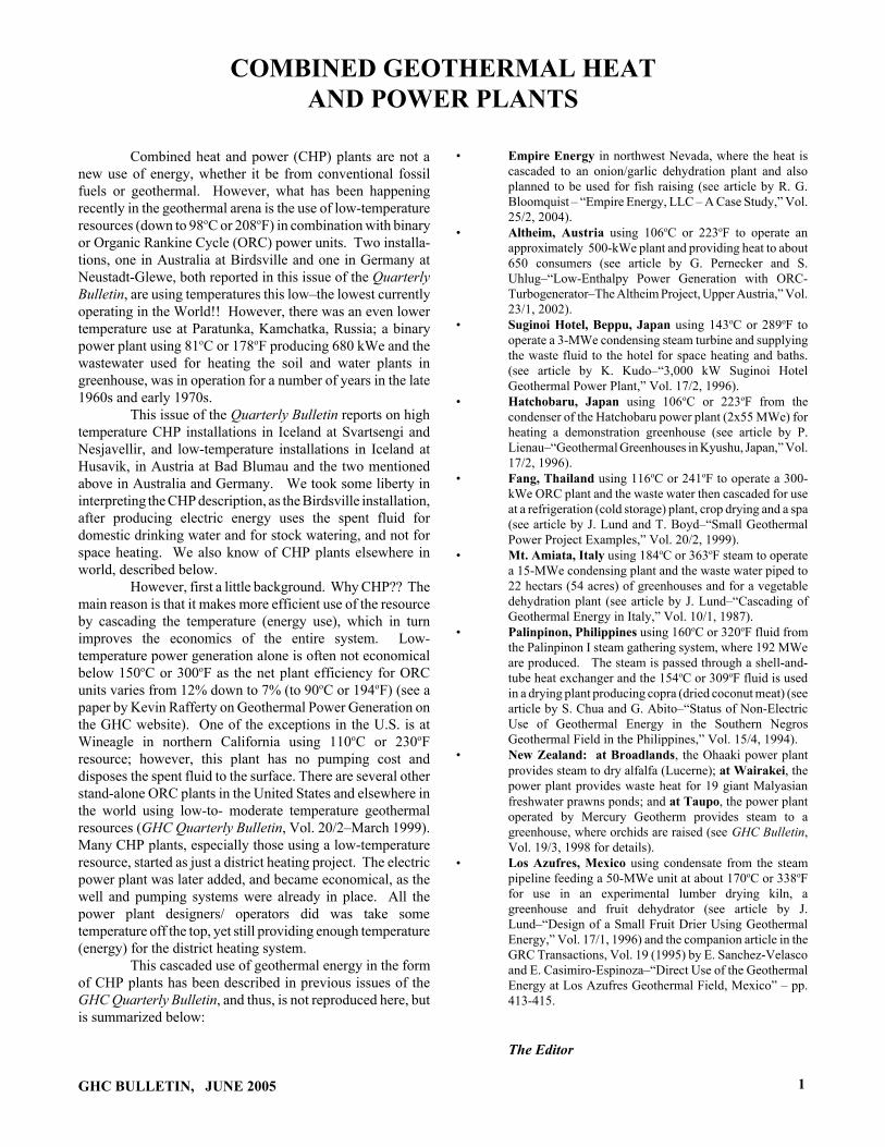
UTILIZATION OF THERMAL POWERAs stated previously, much emphasis was assigned to
obtaining flexibility within the Energy Center’s operationalsystem, thereby enabling the most feasible/economical usageof the thermal energy at all times. Currently the pillars of theoperation are the district heating services it provides and theelectricity production. These two operational functionsprovide the Húsavík Energy with most of its revenue. Theindustrial use of 80oC water is also important to the operation,having the potential to expand should market conditionschange favorably.
At present, there is no 120oC water available forindustrial utilization when electricity production is running atfull capacity. However nothing prevents the delivery of 120oCwater to industry outside high load periods of electricityproduction. When the demand for 120oC for industrial usebecomes sufficient, additional wells will be drilled atHveravellir. All piping and equipment needed for thetransportation of this water to industrial consumers is alreadyin place.
Heat energy for district heating, electricity productionand industry is defined as priority energy. When the load ratioof these three factors is at its optimum, all hot waterwithdrawn can be utilized down to a temperature of 35oC, andat periods of lower loads down to 20oC. Large amounts of 20-35oC hot water resulting from the production remain
Table 2. Utilization of Thermal Power Above 4oCTotal power from geothermal field 62.2 MW 100%
Power from wells H1, H10 and H16 48.5 MW 78%Power from hot springs 13.7 MW 22%Sold power 25.2135 MW 41%Space heating (75o- 35oC) 10.8 MW 17%Tap water (bathing, washing) (75o- 4oC) 2.1 MW 3%Electricity (121o - 80oC) 1.7 MW 3%Industry, 120oC (121o - 80oC) 0 MW 0%Industry, 80oC (75o- 35oC) 1.6 MW 3%Greenhouses (100o - 35oC) 2.4 MW 4%Snow melting (35o- 15oC) 1.0 MW 2%Fish-farming (27o and 60o- 4oC) 5.6 MW 9%Surplus power utilized 18.1 MW 29%Bathing lagoon (27o- 4oC) 18.1 MW 29%Losses 8.9 MW 14%In pipeline from Hveravellir (124o- 121oC) 1.1 MW 2%In Aðaldalur (100o- 75oC) 0.8 MW 1%In Reykjahverfi (100o- 75oC) 1.3 MW 2%In the old asbestos pipeline (100o- 60oC) 2.6 MW 4%In Húsavík distribution system(80o- 75oC) 1.5 MW 2%In effluent pipeline 1.1 MW 2%In Power Plant 0.5 MW 1%Discarded power 10.0 MW 16%35oC hot water from space heating and industry 9.5 MW 15%15oC hot water from snow melting 0.5 MW 1%
GHC BULLETIN, JUNE 2005 11

unused so potential users of water at these temperatures canpurchase the 20-35oC water at very economical prices. Snowmelting and fish farming are two examples of ideal processesthat utilize water at these temperatures. Presently, this unsoldwater is led to a bathing lagoon constructed south of theEnergy Center. Although this utilization of the water does notprovide Húsavík Energy with any additional revenue, thebathing lagoon has acted towards improving the community atHúsavík in addition to having a positive future influence ontourism in the region.
Table 2. and Figure 4 provide an overview of theutilization of thermal power from the geothermal field fromHveravellir. The overview assumes utilization of thermalpower above the temperature of the cold water supply atHúsavík or 4oC. The summary reflects utilization at maximumload on district heating and electricity production in the year2001 (see Figure 2).
The annual utilization of thermal power differsconsiderably from power utilization at maximum load. Theutilization period of maximum power for the electricityproduction is estimated at around 7,000 hours/year. Theutilization period of maximum power for district heating isestimated as 4,400 hours/year and to industry around 6,000hours/year. One of the results of this discrepancy between thevarious utilization periods is that outside periods ofmaximum load for district heating, more 80oC water thanrequired by demand is produced at the Energy Center.
While market conditions for this surplus of 80oCwater remain unchanged, the water will continue flowing tothe bathing lagoon. Losses in main pipelines and in thedistribution systems are quite uniform throughout the year,resulting in a higher percentile of the annual energyproduction than power at maximum load. Water from hot
springs flows freely into collection pipes and during periodsof low load, when demand does not require its utilization, thiswater flows unused into nearby streams and from there intothe ocean. Table 3 summarizes the estimated annualutilization of thermal energy (above 4oC) withdrawn from thegeothermal field.
CONCLUSIONSThis report describes the utilization of geothermal
energy at Húsavík Energy following changes to the districtheating system performed in 1999-2000.
Since the construction of the new system was com-pleted in the year 2001, the system as a whole has been opera-ted without any problems, except for the Kalina power plant.
From the initial start up many problems wereencountered regarding the Kalina power plant. Immediately atstartup separator 1 caused problems, its performance beingvery poor and a far cry from its capacity. Big droplets ofwater seeped in with the ammonia gas entering the turbine,wearing it down unnecessarily and as well considerablylimiting the plant’s output. The separator was replaced afterall attempts to rectify these problems proved fruitless.
Reducing the pressure in the condenser to its designvalue has also proven problematic despite there being morecooling water available than originally predicted. Thecondenser installed is not of a traditional type. It is a plate-heatexchanger for double phase flow, where the ammonia gasenters in the usual fashion, but the liquid is sprayed in throughspecial nozzles. The placement of these nozzles has beenvaried with positive results, but despite this the performanceof the condenser is less than 100%. Additional heatingsurface (plates) will improve the situation.
Table 3. Annual Uutilization of Thermal Energy Above 4oC. Total energy from the geothermal field 459 GWh 100%
Energy from wells H1, H10 and H16 339 GWh 74%Energy from hot springs 120 GWh 26%Sold energy 135 GWh 29%
Space heating 48 GWh 10%Tap water (baths, washes) 9 GWh 2%Electricity 12 GWh 3%Industry, 120oC 0 GWh 0%Industry, 80oC 10 GWh 2%Greenhouses 10 GWh 2%Snow melting 1 GWh 0%Fish farming 45 GWh 10%Surplus energy utilized 177 GWh 39%
Bathing lagoon 177 GWh 39%Losses 75 GWh 17%
In main pipelines and distribution systems. 75 GWh 17%Discarded energy 68 GWh 15%
Water discarded from district heating 43 GWh 9%Unused water from hot springs 25 GWh 6%
12 GHC BULLETIN, JUNE 2005

Heat losses in draining system
1,1 MW6,7 MW1,1 MW
Temperature of inflowing heat
124-80°C
100-60°C
27-35°C
Thermal energyabove 4°C 62,2 MW Cooling water from
electricity production
23°CEffluent 80°C
27°C
1,7 MW. Electricity4,0 MW. Industry (80°) and greenhouses
10,8 MW. District heating
2,1 MW. Tap water3,7 MW. Fish Farming (from hot springs)
1,0 MW. Snow melting
1,9 MW. Fish farming
18,1 MW. Bathing lagoon and pond
0,0 MW. Industry (120°C) (May 2002)
8,9 MW. Total losses
Temperature of rejected water : 35°C 15°C 4°C
10,0 MW. Rejected
62,2 MW total power
Heat losses in main pipe
Heat losses in main pipe for Aðaldalur, Reykjahverfi, Electrical Power plant and Húsavík district heating system
Figure 4. A flow chart depicting the utilization of thermal energy above 4oC at maximum load.
The acceptance certificate was issued after theNovember 2001 testing. The output was less than calculationsindicted, however the certificate was issued as a result of anagreement with the contractor.
The power plant was operated at that demand forapproximately six months without any problem. At routineinspection in May 2002, damage due to wear was againnoticed. First it was believed that separator 1 was still notfunctioning properly. Further inspection proved the damagewas caused by corrosion of the turbine interior. The bladesare made of 13% Cr steel. The turbine interior has beenreplaced with titanium.
As part of the ongoing betterment of the plant, anoffer of an expander giving some 2,150 kW net under thegiven conditions show that the power plant cycle can still beimproved considerably.
After the turbine repair it is reason to believe that thePower Plant will be an outstanding example of an efficientoperation and efficient multi-use of geothermal energy.
The main difference between the old system and thenew one lies in the utilization of the power contained in steamthat prior to the changes was released into the atmosphere.This power is now used to produce electricity. In addition,Húsavík Energy can now offer 120oC hot water for sale toindustry and the possibility of selling water at temperaturesbetween 80oC and 40oC has improved greatly.
GHC BULLETIN, JUNE 2005
Flexible utilization of the heat was emphasized,enabling the system to utilize the energy as efficiently aspossible under varying conditions at each time. Thisflexibility provides Húsavík Energy with the opportunity ofpurchasing electricity from elsewhere and selling the 121oChot water otherwise used for electricity production to industry,should such utilization provide the company with morerevenue. Hot surplus water now flows to a bathing lagoon,which can be enjoyed by inhabitants and visitors to Húsavík,free of charge. Despite the lagoon not providing HúsavíkEnergy with any direct revenue, it contributes to a morepleasant environment for everyone.
It is the opinion of the report’s authors that theobjectives set forth for the multiple energy system project inHúsavík have been obtained.
ACKNOWLEDGMENTThis paper is an edited version of the one presented
at the International Geothermal Congress 2003 - “MultipleIntegrated Uses of Geothermal Resources” Reykjavik, Iceland,Sept. 2003.
REFERENCEOrkustofnuns/Gax 20/01/98 - The Hveravellir Geothermal
Field, NE-Iceland, Conceptual Model and ReservoirAssessment.
13

SUDURNES REGIONAL HEATING CORPORATIONSVARTSENGI, ICELAND
Geir ThorolfssonSudurnes Regional Heating Corporation
Figure 1. Svartsengi Power Plant aerial view.
INTRODUCTIONThe Svartsengi geothermal plant is a combined heat
and power (CHP) plant. The heating plant supplies hot waterto a district heating system (hitaveita) serving 20,000 people.The total installed capacity of the combined plants atSvartsengi is 46.4 MWe electrical power and 150 MJ/s(MWth) in the form of hot water.
The Svartsengi geothermal area is close to the townof Grindavik on the Rekjanes peninsula and is part of anactive fissure swarm, lined with crater-rows and open fissuresand faults (Figure 1). The high-temperature area has an areaof 2 sq km and shows only limited signs of geothermal activityat the surface. The reservoir, however, contains lots of energyand 12 wells supply the Svartsengi Power Plant with steam.The steam is not useable for domestic heating purposes; sothat, heat exchangers are used to heat cold groundwater withthe steam. Some steam is also used for producing 46.4 MWeof electrical power. Figure 2 shows the distribution systempiping hot water to nine towns and the Keflavik InternationalAirport. The effluent brine from the Svartsengi Plant isdisposed of into a surface pond, called the Blue Lagoon,popular to tourists and people suffering from psoriasis andother forms of eczema seeking therapeutic effects from thesilica rich brine. This combined power plant and regionaldistrict heating system (co-generation) is an interesting andunique design for the application of geothermal energy.
14
THE GEOTHERMAL RESOURCEThe geothermal system at Svartsengi is on the
Reykijanes Peninsula, right on the boundary of the Europeanand American tectonic plates. The power plant was built ona lava field which dates from a volcanic eruption in the year1226. The first well was drilled in 1972. The number ofdrilled wells is currently 20. Of these, 12 are production wellsand one well is used for reinjection.
Below 600 meters, the reservoir temperature isalmost uniform at 240oC, and the geothermal fluid is brinewith salinity approximately 2/3 of seawater, 22,000 ppm totaldissolved solids. Since then, the geothermal system haschanged from being completely water-dominated, to water-dominated with a steam cap. From the steam cap, saturatedsteam is produced at 17 to 24 bar wellhead pressure by fourshallow wells (400 to 600 m). Other wells produce a mixtureof steam and brine, and the range in drilled depth varies from1000 m to over 2000 m.
THE SVARTSENGI PLANT EVOLUTIONThe first heat exchange experiments started in 1974
in a small-scale pilot plant. Deciding from results of thisresearch, a second pilot plant was built in 1976 with enoughcapacity to supply the town of Grindavik with 20 L/s of hotwater. The first plant in Svartsengi, called Power Plant 1, wasbuilt in 1976-78. At the time, it was the first of its kind in the
GHC BULLETIN, JUNE 2005

Figure 2. The Sudurnes Regional Heating System layout.
World, it was the first geothermal power plant using a high-temperature geothermal system for simultaneous productionof hot water for district heating and electrical power. Theengineering and construction of Power Plant 1 was done at thesame time as it was a “fast track project.” Getting the mainplant started as soon as possible was extremely importantbecause oil prices had risen to new world-record highs andalmost all houses in the region were heated with oil.Inexpensive geothermal hot water was badly needed and,therefore, design and construction proceeded simultaneously.
This situation created various problems. Forexample, the plant’s main building was originally designed tohouse two heat-exchange flow streams of 37.5 L/s each.Then, it was decided to double the production capacity andinstall a total of four flow streams in a building originallydesigned for two. One of the consequences was that bulkyand heavy heat exchangers had to be installed in the basement,originally designed to only house pumps.
Right now, the Svartsengi geothermal power plantconsists of the following:
GHC BULLETIN, JUNE 2005
Power Plant 1 commissioned in 1977/78: The installed heatexchange capacity was 150 L/s for the district heating system,corresponding to 50 MJ/s (MWth) thermal power.Additionally, two 1-MWe AEG back-pressure steam turbinegenerators were installed. In the year 2000, half of the heat-exchange system was decommissioned.
Power Plant 2 commissioned in 1981: The installed heatexchange capacity is 225 L/s for the district heatingcorresponding to 75 MJ/s (MWth) thermal power.
In Power Plant 3, a 6-MWe Fuji Electric back-pressureturbine started commercial production on January 1, 1981.
The first part of Power Plant 4 was commissioned inSeptember 1989, with three 1.2-MWe ORMAT ORC units.On these units, water-cooled condensers are utilized. Thesecond part was commissioned in 1993 by adding four 1.2-MWe ORMAT units with air-cooled condensers.
15

0
00
Geothermalwell 242 °C
Brine to theBlue lagoon
Separator6 bar
Separator0,8 bar
Heater-deaerator
1,2 bar Steam fromPower Plant 5
Freshwater tank
Steam wentstack
To reinjection well
Freshwater well 5°C
ORC ORC
Main district heatingpipeline 95- 110°C
Back-pressuresteam turbine
1
2
3 45
67
8
9
10
8
11
12
13
14
15
16
80°C
95°C
25°C
Steam158°C
17
1819 18
19
20 20
21
In 1995, the project for Power Plant 5 started out as arenewal of Power Plant 1. The main reasons were:
• The thermal efficiency was not up to today’sstandards, mainly because the small back-pressuresteam turbines were very inefficient.
• Maintenance facilities in Power Plant 1 wereabsolutely unacceptable due to tightly spacedequipment, there were no overhead crane, high-ambient temperature, and a lot of noise.
• The production capacity of Power Plant 1 was notenough to sustain the hot water consumption of thedistrict heating system during even the warmestsummer days. Thus, it was impossible to shut downPower Plant 2 for more than three consecutive daysfor maintenance. This made all major overhauls ofPower Plant 2 difficult, and influenced the overalloperational reliability.
In Power Plant 5, a 30-MWe Fuji Electric extraction-condensing steam turbine was commissioned in November1999, and in April 2000, a district heating part of 75-MJ/s(MWth) thermal power was commissioned.
The plant maintenance and operating staff, consist of22 men, regularly attend to 12 turbines, specifically, fivesteam turbines and seven Organic Rankine Cycle (ORC) units.In addition, they look after 36 cooling fans, 17 geothermalwells and wellheads, 70 control valves, 100 pumps, 20kilometer pipelines and thousands of valves that requiremaintenance.
THE FLOW STREAMIt is practical to start with the “raw materials” of the
plant, illustrated in Figure 3. The numbers in parenthesesrefer to details shown in Figure 3. We have geothermal steamand brine (1) and cold freshwater (2). Brine (1) at 240oC flowsinto the wells through the holes in a slotted liner. On its wayup, the brine starts to boil because of the pressure drop. In thewellhead (3), there is a mixture of steam and brine at about 16bar. The pressure is reduced to 6 bar before the mixture entersthe connecting pipelines to the separators (4). From theseparators, steam goes to the back-pressure turbine (5). Back-pressure steam (6) is consumed either by the heat exchangers(7) or the ORCs (8). The back-pressure is controlled bycontrol valves (9) venting the steam to the atmosphere throughexhaust stacks (10).
The brine (11) from the separator (4) is flashed intoa low-pressure separator (12) operating at 0.8 bar. The brinethen flows through a barometric pipe (13) into the “BlueLagoon.” From this brine, silica precipitates rapidly andmakes the normally permeable lava practically watertight, andthus, the “Blue Lagoon” is formed in a trough in the lave field,about 20 meters above groundwater level.
The cold 5oC freshwater (2) is pumped from shallowwells and rifts about 5 km north of the power plant. The firststage in the heating process is the condenser of the watercooled ORCs (14). Here the water is heated to 25oC. Thenext stage in the production of district heating water is a directcontact heat exchanger (15); where, the water is heated againstthe stream of low-pressure steam. At the same time, de-aeration (degassing) of the water takes place. The deaerationis essential to prevent the water corroding the steel district-
Figure 3. Svartsengi Power Plant flow diagram.
16 GHC BULLETIN, JUNE 2005
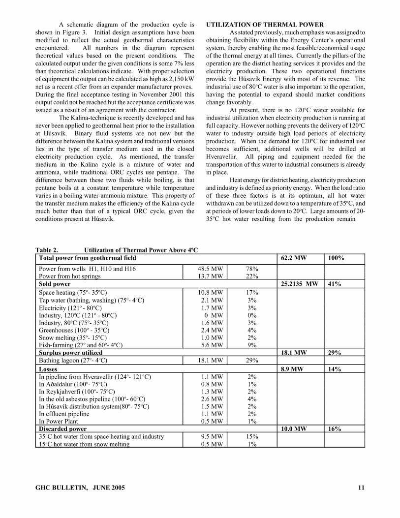
Figure 4. Power Plant 5 flow diagram.
heating pipework. In the deaeration process, dissolved oxygenis eliminated. The deaerated water is pumped (16) through aseries of plate heat exchangers; the first one heats the water toabout 95oC using back-pressure steam and the second (17) toover 100oC or up to 117oC depending on demand of thedistrict heating system.
The ORC (8) is a vapor power cycle. The workingfluid in the cycle is isopentane, a hydrocarbon with a boilingpoint of 27oC at atmospheric pressure. The back-pressuresteam is used to heat the isopentane in a vaporizer (18) atapproximately 6 bar pressure. The isopentane gas is thenexpanded in a turbine (19) which turns a generator. Acondenser (14) receives the gas from the turbine, the heat isremoved with cooling water and the gas is condensed into aliquid at atmospheric pressure. Finally, the cycle is closed bypumping (20) the isopentane liquid again, under pressure, intothe vaporizer.
Finally, the condensate is mixed with brine andinjected back to the geothermal reservoir (21). The flowstream of Power Plant 5 is shown in Figure 4.
POWER PLANT OV-5The new power plant at Svartsengi (OV-5) is
designed for 3 MWe electricity generation and 70 MWtheating output (Figure 4). The district heating part is designedto heat from about 23oC to 90-95oC, and deaerate 240 kg/s ofpre-heated freshwater coming from the ORMAT turbines.The pumps, final-heaters and coolers pump 70 kg/s of 85oCwater to the town of Grindavik and/or 240 kg/s of 110-115oCwater to the town of Njardvik. The maximum pumped in OV-5 to these towns is 240 kg/s. Turbine extractions supply
GHC BULLETIN, JUNE 2005
enough low-pressure steam for after-heating and final-heatingof the district heating water.
It is also possible to receive up to 150 kg/s of districtheating water at about 95oC from Power Plant 2 (OV-2), andheat it to 110-115oC, together with the water produced by OV-5. This solution is adopted because the steam in OV-5 isextraction steam (2.5 bara); whereas, the steam in OV2 ishigh-pressure steam (6.5 bara) that has been used as possiblefor electrical production. OV-2 pumps this water through thefinal heaters in OV-5. In this way, OV-5 can simultaneouslysupply 320 kg/s of 110-115oC hot water to the Njardvikpipeline and 70 kg/s of 85oC hot water to the Grindavikpipeline. Figure 4 shows a flow diagram of the OV-5 powerplant.
The turbine is designed to operate at full-load andalso supply extraction steam for the district heating system. Ifthe power is reduced, eventually the extraction steam pressurebecomes too low to be used for the district heating heatexchangers, and instead of the extraction steam, the high-pressure steam, taken through the bypass valves, must be usedto heat the district heating water.
The high steam pressure to the turbine will becontrolled by the existing control valves in OV-2. In addition,the turbine will be equipped with a valve that reduces theturbine power if the steam pressure drops below 6.5 bara.
The medium pressure (first extraction) varies with thedistrict heating load, 2.7 to 3 bara. If the turbine load isreduced, this pressure drops. In order to maintain minimumpressure, a bypass valve controls steam from the high-pressuresteam supply in order to prevent the medium pressure fromdropping below 2.5 bara.
17

The low pressure (second extraction) varies with thedistrict heating load (1.4 bara at maximum and 1.9 bara at theminimum district heating load). A control valve betweenpower plants OV-5 and OV-2 controls the extraction pressurebased on a variable set-point that depends on the districtheating load as measured by a flow meter. It is assumed thatthe turbine is run at maximum load (30 MWe). If the turbineload is reduced, the extraction pressure drops below 1.3 baraat some point. Then, a bypass control valve opens to maintainthe pressure at 1.3 bara. At the same time, the check valve re-duces the steam coming from the extraction. Chimney valvesin OV-2 control the pressure at 1.3 bara at that side, so that the6-MWe turbine and the ORMAT turbine will not be disturbedbecause of variability in low-pressure steam in OV-5.
The condenser pressure is controlled by thetemperature of the cooling water from the cooling tower. Themixture of condensate water with brine is controlled by twovalves that are operated by the same regulator (oneopens–whereas, the other closes).
CONCLUSIONSThe total performance of the new geothermal co-
generation power plant at Svartsengi is improved by usingturbine extractions, instead of high pressure steam, to heatfreshwater to 110oC in heat exchangers. Energy balancecalculations show that the utilization efficiency of the powerplant OV-5 is improved by 15% with this type of operationand by 14-22% at different heat loads. The turbine modelshows that at 21-24 MWe, electrical output and different heatloads, the pressure of the first and second extractions dropsbelow 2.5 bara and 1.3 bara, respectively. At this point, it isnecessary to supply high pressure steam to the heatexchangers.
18
Geothermal power plants, particularly those operatingon the flash-steam principle, offer the opportunity to combineelectricity generation with direct heat applications. The latterutilization can be accomplished using the thermal energyavailable in a waste brine and rejected heat in a condenser toheat freshwater, which can then be distributed to a variety ofend users. The technical feasibility and design of such co-generation power plants depend on a number of factors,including the reservoir temperature of the geothermal fluid,the type of flash system used in the power plant (single- ordouble-flash), the distance to end users and the types ofapplications. The climate, topography and cost of otherenergy alternatives will also influence the final decision onwhether to use geothermal co-generation power plants.
ACKNOWLEDGMENTThis paper is an edited summary of two papers
presented at the World Geothermal Congress 2000(WGC2000) and 2005 (WGC2005): “Simulation andPerformance Analysis of the New Geothermal Co-GenerationPower Plant (OV-5) at Svartsengi” by Soltoni-Hosseini,Masoud; Sigurdsson, Hallgrimur G. and Geir Thorolfsson,WGC2000, Japan and”Maintenance History of a GeothermalPlant: Svartsengi Iceland” by Geir Thorolfsson, WGC2005,Turkey.
GHC BULLETIN, JUNE 2005

HITAVEITA REYKJAVIKURAND THE NESJAVELLIR GEOTHERMAL
CO-GENERATION POWER PLANTEdited by John W. Lund
Geo-Heat Center
BACKGROUNDWhen Ingólfur Arnarson sighted land on the voyage
which would make him the first settler in Iceland, he threw thepillars of his high seat overboard and relied on the gods todirect him to where he should settle. His slaves found themwashed ashore in a bay where “smoke” rose out of the ground.Therefore, they called it Reykjavik, “Smoky Bay.” But thesmoke after which Iceland’s capital is named was not theresult of fire, but was rather steam rising from hot springs.
Ancient records only mention the use of geothermalsprings for washing and bathing. The best known examplesare the Thvottalaugar (washing pools) in what is nowLaugardalur in Reykjavik, and the hot pool where saga writerSnorri Sturluson bathed at his farm in Reykholt in westernIceland.
The first trial wells for hot water were sunk by twopioneers of the natural sciences in Iceland, Eggert Ólafssonand Bjarni Pálsson, at Thvottalaugar in Reykjavik and inKrísuvík on the southwest peninsula, in 1755-56. Furtherwells were sunk at Thvottalaugar in 1928 through 1930 insearch of hot water for space heating. They yielded 14 litersper second at a temperature of 87oC, which in November 1930was piped three kilometers to Austurbejarskóli, a school inReykjavik which was the first building to be heated bygeothermal water. Soon thereafter, more public buildings inthat area of the city as well as about 60 private houses wereconnected to the geothermal pipeline from Thvottalaugar.
The results of this district heating project were soencouraging that other geothermal fields began to be exploredin the vicinity of Reykjavik in Mosfellssveit, by Laugavegur(a main street in Reykjavik) and by Ellidaár (the salmon river)flowing at that time outside the city but now well within itseastern limits. Results of this exploration were good. A totalof 52 wells in these areas are now producing 2,400 liters persecond of water at a temperature of 62-1329C.
Reykjavik Energy (Orkuveita Reykjavikur) wasestablished in 1999 by the merger of Reykjavik DistrictHeating and Reykjavik Electricity. The company isresponsible for distribution and sale of both hot water andelectricity as well as the water works in the city. The totalnumber of employees is 492 and the turnover in 2003 was 183million US$.
District heating in Reykjavik began in 1930 whensome official buildings and about 70 private houses receivedhot water from geothermal wells close to the old thermalsprings in Reykjavik. Reykjavik District Heating (nowReykjavik Energy) was formally established in 1943 whenproduction of hot water from the Reykir field, 17 km from the
GHC BULLETIN, JUNE 2005
city, started. Reykjavik Energy is by far the largest of the 26municipality-owned geothermal district heating systems inIceland. It utilizes low-temperature areas within and in thevicinity of Reykjavik as well as the high-temperature field atNesjavellir, about 27 km away. Today, it serves about180,000 people or practically the whole population inReykjavik and six neighboring communities (Table 1).
Table 1. Reykjavik Energy - District Heating2003
Number of people servedVolume of houses servedWater temperature at user endNumber of wells in useInstalled capacityPeak load 2003Total pipe lengthWater delivered
179,08542,607,000 m3
75oC62830 MWt593 MWt2,157 km59,600,000 m3/year
Figure 1 is a simplified flow diagram of theReykjavik district heating system showing the Nesjavellirplant.
THE DISTRIBUTION SYSTEMThe geothermal water from Reykir in Mosefellsbær
flows through a main pipeline to six reservoir tanks justoutside Reykjavik that hold 54 million liters. From there, thewater flows to six storage tanks on Öskjuhlíó in midReykjavik holding 24 million liters. Nine pumping stations,distributed throughout the servicing area, pump the water tothe consumers. The water from Nesjavellir flows to two tankson the way to Reykjavik that hold 18 million liters. Fromthere, the heated water flows along a main pipeline to thesouthern part of the servicing area. The heated freshwater andthe geothermal water are never mixed in the distributionsystem but kept separated all the way to the consumer.
The length of the pipelines in the distribution systemis about 1300 km. This includes all pipelines from the wellsto the consumer. The main pipelines are 90 cm in diameter.The pipe from the main line to the consumer is usually 2.5 cmin diameter. Some of the pipes laid in 1940 are still in use.They were originally insulated with turf and red gravel. Thenewer pipes are insulated with foam or rock wool.
Reykjavik Energy uses either single or a doubledistribution system (Figure 2). In the double system, the usedgeothermal water from radiators runs back from the consumerto the pumping stations. There, it is mixed with hotter
19
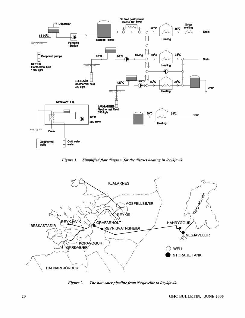
Figure 1. Simplified flow diagram for the district heating in Reykjavik.
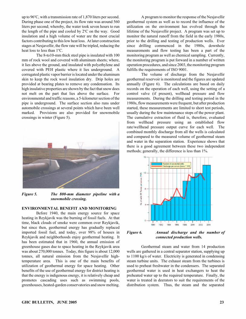
Figure 2. The hot water pipeline from Nesjavellir to Reykjavik.
20 GHC BULLETIN, JUNE 2005

geothermal water and serves to cool that water to the proper80oC, before being re-circulated. In the single system, thebackflow drains directly into the sewer system. The utilityserves about 170,000 people, and in 2002, they used about 63million cubic meters of water, of which 7 million are recycledbackflow waters. In the coldest periods, about 3800 liters persecond are required for space heating. About 85% of the hotwater from Reykjavik Energy is used for space heating, 15%being used for bathing and washing. After the hot water hasbeen used for space heating, it is 25-40oC. In recent years, ithas become increasingly common to use this water to meltsnow off pavements and driveways. Although geothermalenergy is sustainable, it is necessary to make sensible use ofit. It is most important to insulate buildings and to installthermostatic controls to conserve the heat. Consumers pay forthe geothermal water by volume in Reykjavik. It is, therefore,to their advantage to use the water wisely. The price ofthermal water in Reykjavik is approximately one-third of theprice of heating with oil.
NESJAVELLIR PLANTThe Nesjavellir Geothermal Field is a high-enthalpy
geothermal system within the Hengill Central Volcano insouthwestern Iceland. The Nesjavellir Geothermal PowerPlant was commissioned in 1990, following an intensivedrilling and testing phase in the 1980s. By that time, 14production boreholes had been drilled, and all except one weresuccessful. Initially, the plant produced about 560 L/s of 82oChot water for district heating (100 MWt), using geothermalsteam and water to heat cold groundwater. In 1991, thecapacity was expanded to 150 MWt, and 1998 to 200 MWt.At that time, the production of electricity commenced with theinstallation of two 30-MWe turbines. In 2001, the thirdturbine was installed, increasing the capacity to 90 MWe. In2003, the hot water production was increased to 290 MWt,and the fourth electricity turbine will be online production in2005, bringing the capacity to 290 MWe. The stepwiseincreases in production are summarized in Table 2. Initially,only four geothermal wells were connected to the plant, butgradually more wells have been connected as the capacity ofthe power plant has been increased. Presently, 14 boreholesare connected to the Nesjavellir plant, including five newwells drilled in 1999-2003.
Table 2. Co-Generation of Electricity and HotWater at Nesjavellir
Hot Water Electricity
L/s MWt MWe
199019911998200120032005
560840
1120
1640
100150200
290
6090
120
GHC BULLETIN, JUNE 2005
The modular development of the Nesjavellir PowerPlant is a good example of the development of a geothermalresource. Initially, the reservoir was tested with relativelysmall discharge/production, but with an intensive monitoringprogram and revisions of a numerical model of the resourcehas allowed increased production in line with the knownpotential of the field.
Plant OperationA mixture of steam and geothermal brine is
transported from the wells to a central-separation station at200oC and 14 bar. After being separated from the brine, thesteam is piped through moisture separators to steam heatexchangers inside the plant building. The steam can be pipedto steam turbines for co-generation of electricity. Unutilizedsteam is released through a steam exhaust.
In the steam heat exchangers consisting of 295titanium plates, the 120oC steam is cooled under pressure intocondensate whose heat is then transferred to cold freshwaterin condensate heat exchangers. The condensate cools downin the process to 20oC.
Separated geothermal brine has its heat transferred tocold freshwater by geothermal brine heat exchangers
Cold water at 4oC is pumped from wells at Grámelur,near the shore of Lake Thingvallavatn, to a storage tank by thepower house. From there, it is pumped to the steam heatexchangers; where, its temperature is raised to 85-90oC.
Since the freshwater is saturated with dissolvedoxygen that would cause corrosion after being heated, it ispassed through deaerators; where, it is boiled at low volumepressure to remove the dissolved oxygen and other gases,cooling it to 82-85oC as described earlier.
Finally, a small amount of geothermal steamcontaining acidic gases is injected into the water to rid it ofany remaining oxygen and lower its pH, thereby preventingcorrosion and scaling.
A flow diagram of the process is shown in Figure 3.
DistributionThe Nesjavellir power station is situated at an
elevation of 177 meters above sea level (Figure 4). The wateris pumped by three 900-kW (1250-hp) pumps through a mainpipeline of 900 millimeters in diameter to a 2000-m3 storagetank in the Hengill area at an elevation of 406 meters.
From there, the water flows by gravity, through apipeline which is 800 millimeters in diameter, to storage tankson Reynisvatnheidi and Grafarholt on the eastern outskirts ofReykjavik (Figure 2). Those tanks are at an elevation of 140meters above sea level, and have control valves to regulate theflow of water through the pipeline and maintain a constantwater level in the tank in the Hengill area.
From the storage tank, near Reykjavik, the water isfed through pipelines to the communities which are served byOrkuveita Reykjavikur.
From Nesjavellir to Grafarholt, the transmission pipemeasures about 27 kilometers in length, and has fixed andexpansion points every 200 m. It is designed to carry water at
21

WELL HEADSILENCERS
PRODUCTION WELLS
WELL HEADSILENCERS
PRODUCTION WELLS
STEAMSEPARATORS
STEAMSEPARATORS
MISTELIMINATORS
MISTELIMINATORS
DEAERATORS
GEOTHERMALBRINE HEATEXCHANGER
STEAMCONDENSER
GEOTHERMALBRINE HEATEXCHANGER
CONDENSATEHEAT
EXCHANGERS
STEAM HEATEXCHANGER
TURBOGENERATOR
TURBOGENERATOR
MAIN PUMPS
MAIN PUMPS
COLD WATER TANK
COLD WATERPUMPS
TOREYKJAVIK186 kg/s
2450 kJ/kg
154 kg/s
32 kg/s
150 kg/s
4 kg/s
0 kg/s
344 kg/s1350 kJ/kg
268 kg/s
8 bara
11 kg/s
5 kg/s
257 kg/s 167 oC
103 kg/s
170 oC108 kg/s 0 kg/s
0 kg/s
46 MW
36 MW
15 bara 198 oC
2.0 bara 120 oC
0 kg/s
88 oC
88 oC
2224 kg/s4 oC
0.6 kg/s
0.56bara
1046 kg/s
66 kg/s4 oC
0.56bara
1112 kg/s
1046 kg/s
66 kg/s
0.6 kg/s
Figure 3. Flow diagram of the Nesjavellir plant.
Figure 4. Overview of the Nesjavellir plant site.
22 GHC BULLETIN, JUNE 2005
up to 96oC, with a transmission rate of 1,870 liters per second.During phase one of the project, its flow rate was around 560liters per second; whereby, the water took seven hours to runthe length of the pipe and cooled by 2oC on the way. Goodinsulation and a high volume of water are the most crucialfactors contributing to this low heat loss. At later constructionstages at Nesjavellir, the flow rate will be tripled, reducing theheat loss to less than 1oC.
The 8-to10-mm thick steel pipe is insulated with 100mm of rock wool and covered with aluminum sheets; where,it lies above the ground, and insulated with polyethylene andcovered with PEH plastic where it lies underground. Acorrugated plastic vapor barrier is located under the aluminumskin to keep the rock wool insulation dry. Drip holes areprovided at bearing plates to remove any condensation. Itshigh insulative properties are shown by the fact that snow doesnot melt on the part that lies above the surface. Forenvironmental and traffic reasons, a 5-kilometer section of thepipe is underground. The surface section also runs underautomobile crossings at several points which have been wellmarked. Provisions are also provided for snowmobilecrossings in winter (Figure 5).
Figure 5. The 800-mm diameter pipeline with asnowmobile crossing.
ENVIRONMENTAL BENEFIT AND MONITORINGBefore 1940, the main energy source for space
heating in Reykjavik was the burning of fossil fuels. At thattime, black clouds of smoke were common over Reykjavik,but since then, geothermal energy has gradually replacedimported fossil fuel, and today, over 98% of houses inReykjavik and neighborhoods enjoy geothermal heating. Ithas been estimated that in 1960, the annual emission ofgreenhouse gases due to space heating in the Reykjavik areawas about 270,000 tonnes. Today, this figure is about 12,000tonnes, all natural emission from the Nesjavellir high-temperature area. This is one of the main benefits ofutilization of geothermal energy for space heating. Otherbenefits of the use of geothermal energy for district heating isthat the energy is indigenous energy, it is relatively cheap andpromotes cascading uses such as swimming pools,greenhouses, heated-garden conservatories and snow melting.
GHC BULLETIN, JUNE 2005
A program to monitor the response of the Nesjavellirgeothermal system as well as to record the influence of theutilization on the environment has evolved through thelifetime of the Nesjavellir project. A program was set up tomonitor the natural runoff from the field in the early 1980s,prior to the drilling and testing of production wells. Eversince drilling commenced in the 1980s, downholemeasurements and flow testing has been a part of themonitoring program as well as chemical sampling. Currently,the monitoring program is put forward in a number of writtenoperation procedures, and since 2003, the monitoring programfulfills the requirements of ISO 9001.
The volume of discharge from the Nesjavellirgeothermal reservoir is monitored and the figures are updatedannually (Figure 6). The calculations are based on dailyrecords on the operation of each well, using the setting of acontrol valve (if present), wellhead pressure and flowmeasurements. During the drilling and testing period in the1980s, flow measurements were frequent, but after productionstarted, these measurements are limited to short test periods,usually during the few maintenance stops of the power plant.The cumulative extraction of fluid is, therefore, evaluatedfrom wellhead pressure using an established flowrate/wellhead pressure output curve for each well. Thecombined monthly discharge from all the wells is calculatedand compared to the measured volume of geothermal steamand water in the separation station. Experience shows thatthere is a good agreement between these two independentmethods; generally, the difference is less than 1%.
Figure 6. Annual discharge and the number ofconnected production wells.
Geothermal steam and water from 14 productionwells are gathered in a central separator station, supplying upto 1100 kg/s of water. Electricity is generated in condensingsteam turbine units. The exhaust steam from the turbines isused to preheat freshwater in the condensers. The separatedgeothermal water is used in heat exchangers to heat thepreheated water up to the required temperature. Finally, thewater is treated in deerators to suit the requirements of thedistribution system. Thus, the steam and the separated
23

geothermal water are utilized, in the most economical waypossible, for co-generation of electric and thermal power,which is also good for the environment as less heat is releasedto the atmosphere than in conventional geothermal plants.
Comparison with alternative energy sources showthat CO2 and sulphur released to atmosphere, by usinggeothermal energy, is relatively small for the powerproduction at Nesjavellir (e.g., the average amount of CO2
released is within 1% of that of a conventional oil or coal-firedpower plant of similar capacity).
ACKNOWLEDGMENTSThis article is an edited summary of materials from
the following papers:
• Ballzus, Claus; Frimannson, Hreinn; Gunnarsson,Gunnar Ingi and Ingolfur Hrolfsson, 2000. “TheGeothermal Power Plant at Nesjavellir, Iceland,”Proceedings of the World Geothermal Congress2000, Japan.
24
• Grislason, Gestur; Ivarsson, Gretav; Gunnlangsson,Einar; Hjartarson, Arnar; Björnsson, Brimur andBendikt Steingrimsson, 2005. “ProductionMonitoring as a Tool for Field Development - ACase History from the Nesjavellir Field, Iceland,”Proceedings of the World Geothermal Congress2005, Turkey.
• Gunnlangsson, Einar and Gestur Gislason, 2003.“District Heating in Reykjavik and ElectricalProduction Using Geothermal Energy,” Proceedingsof the International Geothermal Conference 2003,Reykjavik, Iceland.
• Lund, John W. (editor), 1996. “HittaveitaReykjavikur and the Nesjavellir Geothermal Co-Generation Power Plant,” Geo-Heat CenterQuarterly Bulletin, Vol. 18, No. 1 (Nov.), KlamathFalls, OR.
GHC BULLETIN, JUNE 2005

HOT ARTESIAN WATER POWERS ANOUTBACK TOWN IN AUSTRALIA
Prame N. ChopraDepartment of Earth & Marine Sciences
Australian National UniversityCanberra, Australia
INTRODUCTIONThe small town of Birdsville (139o53’E 25o21’S) is
situated in arid south west Queensland approximately 1000miles northwest of the state capital Brisbane (Figure 1) and onthe edge of the Simpson Desert. Because of its remotelocation, the town is not connected to the Australian nationalpower grid and requires its own power generation facilities.Established in the 1870s, Birdsville takes its name from theprolific bird life that soon arrives when the nearby DiamantinaRiver intermittently fills with water. The town currently hasa population of around 100 people and is sustainedeconomically mainly by adventure tourism.
Figure 1. The location of Birdsville and the GreatArtesian Basin.
The town’s need for electric power follows a familiarseasonal pattern with highest demand in the hot summermonths when air-conditioning is used extensively and arelatively low demand in winter. This demand cycle from thetown’s small population sees less than 120 kW of powerrequired in winter and upwards of 250kW needed in summer.The one exception is during the town’s once yearly “racesweekend” in spring when the population can swell to morethan 5000. The Birdsville Races is a major tourist event thatdraws tourists from all over Australia, many of whom arrivein light aircraft. As a result, the town has an excellent all-weather airstrip (Figure 2) something quite unusual for a townof its size.
To cope with the annual variations in the demand forelectricity an integrated mix of generation systems are used:
GHC BULLETIN, JUNE 2005
Figure 2. The town of Birdsville with its airstrip inthe foreground and the Diamantina Riverbehind the town.
• A geothermal power station with a nominal powerrating of 150kW,
• A liquefied petroleum gas (LPG) generator set witha rating of 300 kW, and
• Two 150 kW diesel generator sets.
The geothermal power system is installed on a freeflowing artesian bore that was drilled to a depth of 1230 m toprovide the town’s water supply approximately 50 years ago.The water flows through a 6-in.casing to surface at a tempera-ture of 98oC and a rate of 27 L/s. The source of this water isan aquifer in the underlying Great Artesian Basin whichunderlies approximately 1.7 million km2 of central and easternAustralia (Habermehl, 1980).
A geothermal power station (Figure 3) was originallyinstalled on the bore in 1989 and commenced operation in1992 (Burns, et al, 2000). However, the original systemsuffered from a number of technical problems centered on theuse of R114 chlorofluorohydrocarbon as the working fluid. In1999 the plant was upgraded with a grant of A$95,300(US$73,900) from the Queensland Sustainable EnergyInnovation Fund and support from Ergon Energy CorporationLtd.
The upgrade shown schematically in Figure 4involved:
25

• Conversion from the R114 chlorofluorohydrocarbonworking fluid previously used to isopentane which ismore volatile and produces a larger volume of vapor.
• Installation of a new plate heat exchanger, a newmulti-stage liquid pump and larger diameter pipesand fittings to handle the larger volumes of the newworking fluid.
Figure 3. The Birdsville Geothermal Power Stationis situated on a free flowing bore a mile orso out of town (Australian BroadcastingCorporation).
Figure 4. Schematic diagram of the BirdsvilleGeothermal Power Station (QueenslandEnvironmental Protection Agency).
Some of the 81oC outlet water from the power stationis piped into Birdsville for the town’s limited water supplyrequirements. The remainder is flowed into a channel (Figure5); where, it is used to water stock animals once it hastravelled far enough to cool down.
The Birdsville geothermal power plant now provides120kW of net power output after parasitic losses of 30kW.
26
The latter are principally associated with the operation of theplant’s pumps. With a capacity factor of >95%, thegeothermal power system is so reliable that it provides all ofthe town’s electricity needs at night and during the coolerwinter months when air-conditioning is not required(Queensland EPA, 2002). An automatic control system andradio telemetry links the geothermal system with the town’sLPG and diesel powerhouse 1½ miles away. The powerhouseis shut down when the geothermal system is able to satisfy thetown’s demand for electricity.
Figure 5. The outlet water from the power station isflowed in a channel until it has cooledsufficiently for use by stock animals(Australian Broadcasting Corporation).
In the 2002-03 financial year, the geothermal systemprovided 529,326 kWh to the town of a total power generationof 1,630,985 kWh. This saves 42,000 gallons of diesel fuelannually at a saving of A$135,000 (US$104,700) and 430tonnes of CO2 emitted.
The geothermal power station is currently shut downfor a A$100,000 (US$75,600) upgrade to improve buildingventilation and to install isopentane gas detectors for improvedplant safety. It is expected that the power station will be backon-line in August 2005.
REFERENCESBurns, K. L.; Weber, C.; Perry, J. And H. J. Harrington, 2000.
“Status of the Geothermal Industry in Australia,”Proceedings,World Geothermal Congress 2000,Japan, pp. 99-108.
Habermehl, M. A., 1980. “The Great Artesian Basin.Australia,” BMR Journal of Geology andGeophysics, 5, 3-38.
Queensland EPA, 2000. “Birdsville Geothermal PowerStation,” Queensland Sustainable EnergyInnovation Fund Fact Sheet, QueenslandE n v i r o n m e n t a l P r o t e c t i o n A g e n c y .http://www.epa.qld.gov.au/publications/p00834aa.pdf/Birdsville_geothermal_power_station.pdf
GHC BULLETIN, JUNE 2005
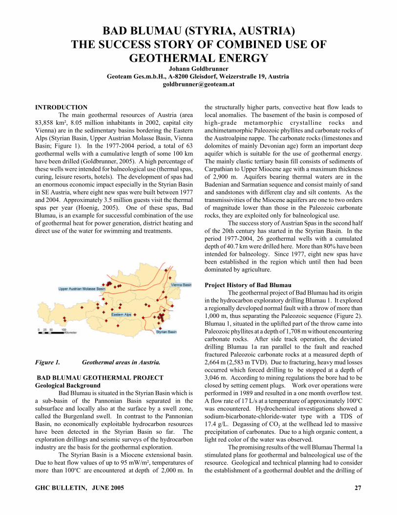
BAD BLUMAU (STYRIA, AUSTRIA)THE SUCCESS STORY OF COMBINED USE OF
GEOTHERMAL ENERGYJohann Goldbrunner
Geoteam Ges.m.b.H., A-8200 Gleisdorf, Weizerstraße 19, Austria [email protected]
INTRODUCTION The main geothermal resources of Austria (area
83,858 km², 8.05 million inhabitants in 2002, capital cityVienna) are in the sedimentary basins bordering the EasternAlps (Styrian Basin, Upper Austrian Molasse Basin, ViennaBasin; Figure 1). In the 1977-2004 period, a total of 63geothermal wells with a cumulative length of some 100 kmhave been drilled (Goldbrunner, 2005). A high percentage ofthese wells were intended for balneological use (thermal spas,curing, leisure resorts, hotels). The development of spas hadan enormous economic impact especially in the Styrian Basinin SE Austria, where eight new spas were built between 1977and 2004. Approximately 3.5 million guests visit the thermalspas per year (Hoenig, 2005). One of these spas, BadBlumau, is an example for successful combination of the useof geothermal heat for power generation, district heating anddirect use of the water for swimming and treatments.
Figure 1. Geothermal areas in Austria.
BAD BLUMAU GEOTHERMAL PROJECTGeological Background
Bad Blumau is situated in the Styrian Basin which isa sub-basin of the Pannonian Basin separated in thesubsurface and locally also at the surface by a swell zone,called the Burgenland swell. In contrast to the PannonianBasin, no economically exploitable hydrocarbon resourceshave been detected in the Styrian Basin so far. Theexploration drillings and seismic surveys of the hydrocarbonindustry are the basis for the geothermal exploration.
The Styrian Basin is a Miocene extensional basin.Due to heat flow values of up to 95 mW/m², temperatures ofmore than 100oC are encountered at depth of 2,000 m. In
GHC BULLETIN, JUNE 2005
the structurally higher parts, convective heat flow leads tolocal anomalies. The basement of the basin is composed ofhigh-grade metamorphic crystalline rocks andanchimetamorphic Paleozoic phyllites and carbonate rocks ofthe Austroalpine nappe. The carbonate rocks (limestones anddolomites of mainly Devonian age) form an important deepaquifer which is suitable for the use of geothermal energy.The mainly clastic tertiary basin fill consists of sediments ofCarpathian to Upper Miocene age with a maximum thicknessof 2,900 m. Aquifers bearing thermal waters are in theBadenian and Sarmatian sequence and consist mainly of sandand sandstones with different clay and silt contents. As thetransmissivities of the Miocene aquifers are one to two ordersof magnitude lower than those in the Paleozoic carbonaterocks, they are exploited only for balneological use.
The success story of Austrian Spas in the second halfof the 20th century has started in the Styrian Basin. In theperiod 1977-2004, 26 geothermal wells with a cumulateddepth of 40.7 km were drilled here. More than 80% have beenintended for balneology. Since 1977, eight new spas havebeen established in the region which until then had beendominated by agriculture.
Project History of Bad BlumauThe geothermal project of Bad Blumau had its origin
in the hydrocarbon exploratory drilling Blumau 1. It exploreda regionally developed normal fault with a throw of more than1,000 m, thus separating the Paleozoic sequence (Figure 2).Blumau 1, situated in the uplifted part of the throw came intoPaleozoic phyllites at a depth of 1,708 m without encounteringcarbonate rocks. After side track operation, the deviateddrilling Blumau 1a ran parallel to the fault and reachedfractured Paleozoic carbonate rocks at a measured depth of2,664 m (2,583 m TVD). Due to fracturing, heavy mud lossesoccurred which forced drilling to be stopped at a depth of3,046 m. According to mining regulations the bore had to beclosed by setting cement plugs. Work over operations wereperformed in 1989 and resulted in a one month overflow test.A flow rate of 17 L/s at a temperature of approximately 100oCwas encountered. Hydrochemical investigations showed asodium-bicarbonate-chloride-water type with a TDS of17.4 g/L. Degassing of CO2 at the wellhead led to massiveprecipitation of carbonates. Due to a high organic content, alight red color of the water was observed.
The promising results of the well Blumau Thermal 1astimulated plans for geothermal and balneological use of theresource. Geological and technical planning had to considerthe establishment of a geothermal doublet and the drilling of
27
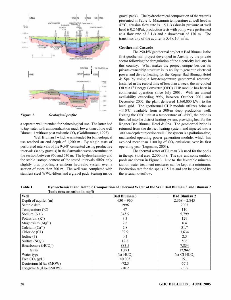
Figure 2. Geological profile.
a separate well intended for balneological use. The latter hadto tap water with a mineralization much lower than of the wellBlumau 1 without post volcanic CO2 (Goldbrunner, 1993).
Well Blumau 3 which was intended for balneologicaluse reached an end depth of 1,200 m. By single tests ofperforated intervals of the 9-5/8" cemented casing productiveintervals (sandy gravels) in the Sarmatian were determined inthe section between 960 and 630 m. The hydrochemistry andthe stable isotope content of the tested intervals differ onlyslightly thus proofing a uniform hydraulic system over asection of more than 300 m. The well was completed withstainless steel WWL-filters and a gravel pack (casing inside
gravel pack). The hydrochemical composition of the water ispresented in Table 1. Maximum temperature at well head is47oC; artesian flow rate is 1.5 L/s (shut-in pressure at wellhead is 0.2 MPa), production tests with pump were performedat a flow rate of 8 L/s and a drawdown of 130 m. Thetransmissivity of the aquifer is 5.4 x 10⁻⁵ m2/s.
Geothermal CascadeThe 250-kW geothermal project at Bad Blumau is the
first geothermal project developed in Austria by the privatesector following the deregulation of the electricity industry inthis country. What makes the project unique besides itsprivate ownership structure is its ability to generate electricalpower and district heating for the Rogner Bad Blumau Hotel& Spa by using a low-temperature geothermal resource.Installed in the record time of less than a week, the air-cooledORMAT® Energy Converter (OEC) CHP module has been incommercial operation since July 2001. With an annualavailability exceeding 99%, between October 2001 andDecember 2002, the plant delivered 1,560,000 kWh to thelocal grid. The geothermal CHP module utilizes brine at~110oC, available from a 300-m deep production well.Exiting the OEC unit at a temperature of ~85oC, the brine isthen fed into the district heating system, providing heat for theRogner Bad Blumau Hotel & Spa. The geothermal brine isreturned from the district heating system and injected into a3000-m depth reinjection well. The system is a pollution-free,unattended operating power generation module, which hasavoided more than 1100 kg of CO2 emissions over its firstoperating year (Legmann, 2003).
The thermal water of Blumau 3 is used for the poolsin the spa (total area 2,500 m²). The spa and some outdoorpools are shown in Figure 3. Due to the favorable mineral-ization water treatment measures can be kept at a minimum.Production rate for the spa is 1.5 L/s and can be provided bythe artesian overflow.
Table 1. Hydrochemical and Isotopic Composition of Thermal Water of the Well Bad Blumau 3 and Blumau 2(Ionic concentration in mg/l)
Well Bad Blumau 3 Bad Blumau 2Depth of aquifer (m) 630 – 960 2,368 – 2,843Sample date 1996 2003Temperature (oC) 47 110Sodium (Na+) 345.9 5,799Potassium (K+) 3.3 129Magnesium (Mg++) 2.8 6.4Calcium (Ca++) 2.8 31.7Chloride (Cl-) 39.9 3,634Iodine (I-) 0.1 2.5Sulfate (SO4
--) 12.8 508Bicarbonate (HCO3
-) 883.5 7,834 Sum 1,291 17,942Water type Na-HCO3 Na-Cl-HCO3
Free CO2 (g/L) <0.005 15.1Deuterium (d ‰ SMOW) -72.3 -57.5Oxygen-18 (d ‰ SMOW) -10.2 -7.97
28 GHC BULLETIN, JUNE 2005
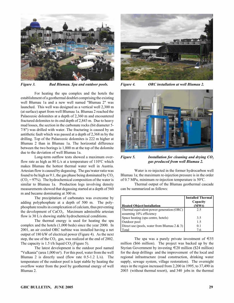
Figure 3. Bad Blumau. Spa and outdoor pools.
For heating the spa complex and the hotels theestablishment of a geothermal doublet comprising the existingwell Blumau 1a and a new well named "Blumau 2" waslaunched. This well was designed as a vertical well 2,300 m(at surface) apart from well Blumau 1a. Blumau 2 reached thePalaeozoic dolomites at a depth of 2,360 m and encounteredfractured dolomites to its end depth of 2,843 m. Due to heavymud losses, the section in the carbonate rocks (bit diameter 5-7/8") was drilled with water. The fracturing is caused by anantithetic fault which was passed at a depth of 2,368 m by thedrilling. Top of the Palaeozoic dolomites is 222 m higher atBlumau 2 than in Blumau 1a. The horizontal differencebetween the two borings is 1,800 m at the top of the dolomitedue to the deviation of well Blumau 1a.
Long-term outflow tests showed a maximum over-flow rate as high as 80 L/s at a temperature of 110oC whichmakes Blumau the hottest thermal water well in Austria.Artesian flow is caused by degassing. The gas/water ratio wasfound to be high as 9:1, the gas phase being dominated by CO2
(CO2 = 97%). The hydrochemical composition of the water issimilar to Blumau 1a. Production logs involving densitymeasurements showed that degassing started at a depth of 560m and became dominating at 300 m.
The precipitation of carbonates was overcome byadding polyphosphate at a depth of 500 m. The poly-phosphate results in complexation of calcium, thus preventingthe development of CaCO3. Maximum admissible artesianflow is 30 L/s showing stable hydrochemical conditions.
The thermal energy is used for heating the spacomplex and the hotels (1,000 beds) since the year 2000. In2001, an air cooled ORC turbine was installed having a netoutput of 180 kW of electrical power (Figure 4). As the nextstep, the use of the CO2 gas, was realized at the end of 2002.The capacity is 1.5 t/h liquid CO2 (Figure 5).
The latest development is the outdoor pool named"Vulkania" (area 1,000 m²). For this pool, water from the wellBlumau 2 is directly used (flow rate 0.5-1.2 L/s). Thetemperature of the outdoor pool is kept stable by heating theoverflow water from the pool by geothermal energy of wellBlumau 2.
GHC BULLETIN, JUNE 2005
Figure 4. ORC installation at well Blumau 2.
Figure 5. Installation for cleaning and drying CO2
gas produced from well Blumau 2.
Water is re-injected in the former hydrocarbon wellBlumau 1a; the maximum re-injection pressure is in the orderof 0.7 MPa, minimum re-injection temperature is 50oC.
Thermal output of the Blumau geothermal cascadecan be summarized as follows:
Heated Object/installation
Installed ThermalCapacity(MWt)
Thermal equivalent power generation (ORC)assuming 10% efficiency
2.5
Space heating (spa centre, hotels) 3.5Outdoor pool 1.5Direct use (pools, water from Blumau 2 & 3) 0.1Total 7.6
The spa was a purely private investment of i55million ($66 million). The project was backed up by theStyrian Government by investing i20 million ($24 million)for the deep drillings and the improvement of the local andregional infrastructure (road construction, drinking watersupply, sewage system, village restoration). The overnightstays in the region increased from 2,200 in 1995, to 37,490 in2003 (without thermal resort), and 340 jobs in the thermal
29

Figure 6. Blumau geothermal project: (1) ORC, (2) CO2 -gas, and (3) district heating.
resort hotel and 170 jobs in regional services have beencreated (Hoenig, 2005).
A schematic of the Bad Blumau project is shown inFigure 6.
REFERENCESGoldbrunner, J., 1993. “Geological and Technical Design of
the Geothermal Project Blumau, Styria.”Unpublished report to Styrian Government (1993).
Goldbrunner, J., 2005. “State, Possible Future Developmentsin and Barrieres to the Exploration and Exploitationof Geothermal Energy in Austria--Country Update.”Proceedings World Geothermal Congress 2005,Antalya Turkey, pp. 24-29.
30
Hoenig, H., 2005. “Geothermal Resources as a Promoter ofRegional Development, The Success Story of theStyrian Volcanic Region.” Proceedings WorldGeothermal Congress 2005, Antalya Turekey, pp.24-29.
Legmann, Hilel, 2003. “The Bad Blumau GeothermalProject: A Low-Temperature, Sustainable andEnvironmentally Benign Power Plant,” Geothermics,Vol. 31, No. 4/6. Aug/Dec 2003, Pergamon.
GHC BULLETIN, JUNE 2005

COMBINED HEAT AND POWER PLANTNEUSTADT-GLEWE, GERMANY
Compiled byJohn W. Lund
Geo-Heat Center
INTRODUCTIONThe Neustadt-Glewe geothermal heating plant was
commissioned in January 1995, supplying exclusively indirect-heat transition the base load of a district heating systemamounting to a thermal output of approximately 11 MWF,thus covering the demand of a major part of the town ofNeustadt-Glewe. The installed geothermal capacity is 6 MW;a gas-fired boiler unit is operated to cover the peak-load. Thesite of Neustadt-Glewe is characterized by the hitherto deepestwells, the highest thermal water temperature and watermineralization compared to all the other geothermal plantsinstalled in Germany by now. In 2003, the plant was extendedby a power generation unit of 210 kWe gross.
This is the first geothermal electric generation plantin Germany, and uses only 98oC (208oF) water, the lowesttemperature used in the world.
Neustadt-Glewe is situated in the north Germanbasin, between the cities of Berlin and Hamburg (Figure 1).
Figure 1. Location of Neustadt-Glewe.
Since 1995, the geothermal doublet in Neustadt-Glewe provides brine at 98oC for a district heating system.The brine is produced from a 2100 to 2300 m (6890 to 7546ft) deep sandstone aquifer. High salt contents of the brine(total dissolved solids = 227 g/L) require the use of resistantmaterials (e.g., titanium) for the heat exchanger equipment.
In the summer of 2003, the heating plant wasextended by a binary-cycle (Organic Rankine Cycle, ORC)and in November of 2003, the first German geothermal powerplant was connected to the grid, providing 210 kWe grosscapacity (performance guarantee, according to ErdwãrmeKraft (2003)). A measuring scheme was installed to supervise
GHC BULLETIN, JUNE 2005
the plant performance and to get operational data of the verylow temperature ORC.
PLANT SETUPThe Neustadt-Glewe plant supplies heat and power
using a parallel-series connection of power plant and heatingstation (Figure 2). The heating station takes priority over thepower plant. The incoming mass flow rate of the brine is splitand a part is fed to the power plant. The brine leaves thepower plant at constant outlet temperature. The two flows,one at initial brine inlet temperature, the other at outlettemperature of the power plant, are joined upstream from theheating station. The mixing temperature should be highenough to meet the heating demand. In summertime, aminimum temperature of 73oC (165oF) is required. To meetthe heating demand in wintertime, higher temperatures arenecessary, amounting up to the initial brine temperature (98oC- 208oF).
Figure 2. Combined heat and power supply inNeustadt-Glewe, parallel connection ofpower plant and heating station.
Unlike common combined heat and power plantswith combustion or the plant setup realized with the Husavikplant, heating station and power plant are competing for thebrine. The power plant is fed with variable mass flow rate ofthe brine at constant temperature; while, the heating station isprovided with a constant mass flow rate at variabletemperature.
31
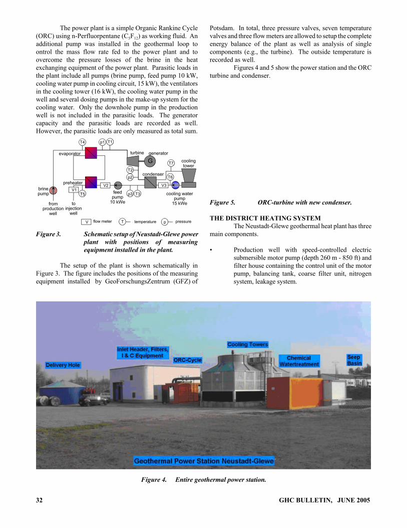
V
V1V2 V3
T4 T1p1
T7
T2
p2
T3
T6
p3T5
pT
toinjection
well
fromproduction
well
brinepump
evaporator
preheater
feedpump
10 kWe
turbine generator
condenser
coolingtower
cooling waterpump
15 kWe
flow meter temperature pressure
G
The power plant is a simple Organic Rankine Cycle(ORC) using n-Perfluorpentane (C5F12) as working fluid. Anadditional pump was installed in the geothermal loop toontrol the mass flow rate fed to the power plant and toovercome the pressure losses of the brine in the heatexchanging equipment of the power plant. Parasitic loads inthe plant include all pumps (brine pump, feed pump 10 kW,cooling water pump in cooling circuit, 15 kW), the ventilatorsin the cooling tower (16 kW), the cooling water pump in thewell and several dosing pumps in the make-up system for thecooling water. Only the downhole pump in the productionwell is not included in the parasitic loads. The generatorcapacity and the parasitic loads are recorded as well.However, the parasitic loads are only measured as total sum.
Figure 3. Schematic setup of Neustadt-Glewe powerplant with positions of measuringequipment installed in the plant.
The setup of the plant is shown schematically inFigure 3. The figure includes the positions of the measuringequipment installed by GeoForschungsZentrum (GFZ) of
Potsdam. In total, three pressure valves, seven temperaturevalves and three flow meters are allowed to setup the completeenergy balance of the plant as well as analysis of singlecomponents (e.g., the turbine). The outside temperature isrecorded as well.
Figures 4 and 5 show the power station and the ORCturbine and condenser.
Figure 5. ORC-turbine with new condenser.
THE DISTRICT HEATING SYSTEMThe Neustadt-Glewe geothermal heat plant has three
main components.
• Production well with speed-controlled electricsubmersible motor pump (depth 260 m - 850 ft) andfilter house containing the control unit of the motorpump, balancing tank, coarse filter unit, nitrogensystem, leakage system.
Figure 4. Entire geothermal power station.
32 GHC BULLETIN, JUNE 2005

• Geothermal heating plant with heat exchanger, peakload gas boiler, various equipment for the heatingnetwork water, process instrumentation and controlsystem, control room, office rooms, demonstrationhall.
• Injection well with filter house containing theinjection pump (not in use), balancing tank, finefilter unit, nitrogen system, slop pit, slop collector.
The thermal water pipe is 1,780-m (5,840-ft) longand connects the wells with the heating plant.
Specific materials such as glass-fiber reinforcedplastic tubes, resin-lined steel tube parts and measures such asinertisation by means of nitrogen loading were applied forprotection from corrosion and precipitation.
The principle of geothermal energy use at theNeustadt-Glewe site is shown in Figure 6.
Figure 6. Schematic of the thermal water loop,.
ECONOMIC AND ENVIRONMENTAL ASPECTSThe Heat Plant
The expenditures on the project including thepurchase of the oil boiler unit in the residential area and thedistrict heat supply system, as well as its extension orrehabilitation, amounted to i 9.45 million ($11.4 million)with i 6.44 million ($7.7 million) referring to the geothermaland heat production units.
The data on heat production in 1998 given in Table1 allows a view of the economic situation. By the end of1998, more than 1,300 households, 20 trade consumers andone industrial enterprise have been supplied withenvironment-friendly heat by the geothermal plant.
Present activities are concentrated on theoptimization of the individual sections of the plant, morerational primary energy use and extension of the supplynetwork through the connection of more heat consumers.
In Neustadt-Glewe, the emission of CO2 was reducedby about 2,700 tons in 1997. About 1.7 million m3 (60 million
GHC BULLETIN, JUNE 2005
ft3) of natural gas were saved. In the course of the by now(1999) four years of operation, there did not occur any failuresaffecting the environment.
Table 1. 1998 Heat Production
Heat Production
Total That of which is geothermal
15,900 MWh15,042 MWh
Primary Energy Source Used
Fuel Oil Natural Gas Geothermal
0%5%95%
Percentage of the Cost Depending on Consumption
Purchase of Gas Purchase of Fuel Oil Power - GHP Power - District Heat Supply
25%0%45%30%
The Power PlantIn Germany, electricity generation from geothermal
heat has only since March 2000 been government-fundedunder the so-called Renewable Energies Act. Electricity fromwind, sun, biomass and hydros have already enjoyed thisprivilege since 1990. The change in legislation aroused theinterest in the use of geothermal energy for power production.
Bewag Aktiengesellschaft & Co. of Berlindeveloped ORC geothermal power plants with the followingkey features:
• Wet cooling towers reducing own consumption to18-20%.
• Cogeneration because the sale of heat would increaserevenues.
Bewag then looked for a project to put the know-howto good account. The geothermal power plant in Neustadt-Glewe, a little town with 8000 inhabitants located 200 km(125 miles) northwest of Berlin, lent itself well for thispurpose.
The high share of geothermal heat in the overall heatvolume supplied to the town of Neustadt-Glewe implied thatspace capacity was available for other uses (electricitygeneration) in the summer months and inter-seasonal periods.In addition, the smoothly operating Neustadt-Glewegeothermal plant was not subject to any geological risks, andalso the operational risk inherent in the small innovative ORCplant was limited.
Another crucial factor for the project was that this200-kWe project could be implemented within the financialframework of the originally planned 125-kWd project with aircooling towers , i.e., of i 800,000 ($960,000) capital costs,out of which i 400,000 ($480,000) were grant-funded. The
33

final costs of the project then amounted to i 950,000 ($1.14million).
ACKNOWLEDGMENTSMaterial for this article was edited from the
following:
Broßmann, Egbert and Marc Koch, 2005. “First Experiencewith the Geothermal Power Plant in Neustadt-Glewe(Germany),” Proceedings, World GeothermalCongress 2005, Turkey, International GeothermalAssociation.
Erdwärmekraft, GbR, 2003. www.erdwaerme-kraft.de.
Köhler, S., 2005. “Analysis of the Combined Heat and PowerPlant Neustadt-Glewe,” Proceedings, WorldGeothermal Congress 2005, Turkey, InternationalGeothermal Association.
Menzel, Heiner; Seibt, Peter and Tosten Kellner, 2000. “FiveYears of Experience in the Operation of theNeustadt-Glewe Geothermal Project,” Proceedings,World Geothermal Congress 2000, Japan,International Geothermal Association.
Seibt, Peter; Kabus, Frank and Peer Hoth, 2005. “TheNeustadt-Glewe Geothermal Power Plant - PracticalExperience in the Reinjection of Cooled ThermalWaters into Sandstone Aquifers,” Proceedings,World Geothermal Congress 2005, Turkey,International Geothermal Association.
ERRATAIn the last issue of the GHC Quarterly Bulletin (Vol.
26, No. 1 - March 2005), an incorrect graph was printed forFigure 5, page 5 of the article in “Greenhouse Heating withGeothermal Heat Pump Systems” by Andrew Chiasson. Thecorrect graph is reproduced here and can be found on ourwebsite at http:/geoheat.oit.edu/bulletin/bull26-1/art2.pdf,where the correct version also appears.