Embed Size (px)
Citation preview

Sensors and Switches in Valves and Flow MetersAn Application Note
Background
Valves control or regulate the flow of gasses or fluids by partially
obstructing, opening or closing the pipeline that carries the media. Valves
are often used in oil and gas, mining, chemical manufacturing, water
reticulation and mining applications. In many of these applications, the
valves are operated manually by a lever, pedal or wheel. Automatic valves
with diaphragms or pistons are often actuated by changes in pressure,
temperature or flow.
Flow meters can measure and regulate volumetric flow, velocity from
which the volumetric flow is determined, and mass flow. The turbine flow
meter translates the mechanical action of the turbine rotating in the liquid
flow around an axis into a user-readable rate of flow (gpm, lpm, etc.). The
turbine wheel is set in the path of a fluid stream. The flowing fluid impinges
on the turbine blades, imparting a force to the blade surface and setting
the rotor in motion. Nearly all flow meters must be installed so that there
is a significant run of straight pipe before and after the location of the flow
meter. This is intended to allow the straight pipe run to “smooth out” any
turbulence produced by the presence of valves, chemical injectors and
diffusers, and changes in pipe direction. (See Figures 1 and 2.)
Solutions
Honeywell manufactures many electronic sensors and electromechanical
switches that may be used in valves and flow meters. They are designed to
deliver system control, fluid level indication, temperature regulation, along
with protection from overheating and starting/stopping the compressor.
Honeywell components provide enhanced reliability, minimize down time,
and improve robustness in most harsh environments. (See Figures 3
and 4.)
Figure 1. Valves in a Bottling Factory
Figure 2. Flow Meter in a Gas Pipeline

APPLICATION NOTE | Sensors and Switches in Valves and Flow Meters | sensing.honeywell.com 2
Figure 3. Sensing and Switching Products Used in Valves and Flow Meters
1
2
3
4
SMART Position SensorSPS Series75mm analog and 225 mm analog and digitallinear configuration
Position SensorSR SeriesDigital position sensor
Motor drivesupply
Pressure sensor
LVDT drive &analog supply
Core and I/Opower
Valve controller
andconditioner
(DSP) Position sensor
SMART positionsensor drive
Motor drive
SMART positionsensor
PressureXDCB
SPOOL
Valve mechanics
Linearforcemotor
CA
N B
us
Signal isolator CAM Xcvr
1
1
2
5
Hall-Effect SensorLCZ or 3000 SeriesSingle, zero speed sensor (LCZ) or high resolution VRS sensor (3000)
6
Basic SwitchMICRO SWITCH BZ, V7, V15, and ZW SeriesLarge, miniature, and subminiature basic switches
Hazardous Location Limit SwitchMICRO SWITCH VPX, CX, LSX, and BX SeriesPremium limit switches in explosion-proof housing
Limit SwitchMICRO SWITCH HDLS and GL SeriesPremium heavy duty and standard global limit switches
Flow Meter 5
46
45 6
Flow Meter
Flowmeter AssemblyMagnetic pick up
3
Figure 4. Switches in Valves
1
2
Explosion-Proof Valve Position IndicatorMICRO SWITCH VPXValve position indicator in explosion-proof housing
2
3
3
4
Basic SwitchMICRO SWITCH™ BZ, V7, V15, and ZW SeriesLarge, miniature, and subminiature basic switchesHazardous Location Limit SwitchMICRO SWITCH LSX, CX, and BX SeriesPremium limit switches in explosion-proof housing
Limit SwitchMICRO SWITCH HDLS and GL SeriesPremium heavy duty and standard global limit switches
1

APPLICATION NOTE | Sensors and Switches in Valves and Flow Meters | sensing.honeywell.com 3
MICRO SWITCH Basic Switches
MICRO SWITCH BZ, V7, V15, and ZW Series ba-
sic switches: Snap-action switches monitor the
position of the valve handle by indicating if the
switch is actuated. These switches are employed
on valves used in non-explosive environments
such as waste water treatment plants and/or
other factory applications. (See Table 1).
Accepted as the world-wide standard “large ba-
sic” switch, MICRO SWITCH BZ Series switches
are used for simple or precision on/off appli-
cation needs. Through the use of optional seal
plungers and covers, the BZ Series is capable of
an IP67 rating and carries UL, CSA, ENEC, and
CE global approvals.
With world-wide package size acceptance and
designed to withstand 100k operations at full
load, MICRO SWITCH V7 Series switches are
used for simple or precision on/off, end of limit,
presence/absence, pressure, and manual oper-
ator interface application needs. The V7 Series
has CE, CSA, and ENEC approvals.
MICRO SWITCH V15 Series switches are similar
to our V7 series, but are designed for applica-
tions requiring greater than or equal to 100 g of
operating force and electrical ratings ranging
from 16 A to 22 A. They have a water-tight option
(V15W Series), and well as UL, cUL, ENEC, and
CQC approvals.
MICRO SWITCH ZW Series subminiature basics
are used for simple or precision ON/OFF appli-
cation needs. These switches combine small size
and light weight with ample electrical capacity
and long life. This water-tight series seals to
IP67 and has UL, cUL, CE, and ENEC approvals.
Hall-Effect Speed Sensors
LCZ Series single zero speed sensor or 3000
Series high resolution VRS sensor: In flow
meter applications Honeywell’s speed sensors
measure flow by monitoring revolutions of the
impeller (an inside propeller). Each revolution of
the impeller equates to the delivery of a certain
amount of fluid. For example, if the user sets a
fluid level of five gallons per minute, the speed
sensor counts the impeller rotation so that the
correct amount of fluid is delivered.
BZ Series Large Basic Switch
VPX Series Valve Position Indicator
Honeywell’s Hall-effect speed sensors use multi-
ple technologies to detect a change in magnetic
field to create an electronic signal for control
system interface. These technologies offer the
ability to detect speed, direction, or position
of a moving ferrous metal or magnetic target.
Sensing is accomplished without contacting the
target, and there are no moving parts. This elimi-
nates mechanical wear of the sensor or target.
The LCZ Series Hall-effect Single Zero Speed
Sensor provides reliable information for flow
control. Its fail-safe and diagnostics functions
(variable reluctance technology) signal the con-
trol system to take contingency actions if there is
a failure in the system.
The 3000 Series High Resolution VRS Sensor
features self-powered operation and direct con-
version of actuator speed to output frequency. It
has simple installation and no moving parts.
MICRO SWITCH Hazardous Location Switches
Hazardous-location limit switches in explo-
sion-proof housings monitor the position of the
valve stem or actuator. As these limit switches
are enclosed in an explosion-proof housing,
any flame path is extinguished inside which
mitigates the risk of causing an explosion at the
switch part. These switch components provide
feedback for user to take action in order to
prevent explosions in hazardous environments.
Hazardous-location switches are employed in
valves in outdoor, above-ground, potentially
explosive environments such as oil and gas or
water treatment applications.
Honeywell’s hazardous location switches are
designed specifically for dangerous indoor and
outdoor locations – where reliability and repeat-
ability are essential.
MICRO SWITCH VPX valve position indicators
are built especially for outdoor use in potentially
hazardous atmospheres as they are rated to
IP66, NEMA 4, 4X, 6, and 13. The switch enclo-
sures are constructed to withstand the pressure
of an internal explosion. Flame paths cool the
exploded gases to a point less than the lowest
safe operating temperature of the surrounding
LCZ Series Speed Sensor
APPLICATION NOTE | Sensors and Switches in Valves and Flow Meters | sensing.honeywell.com 4
gas. The VPX Series versions equipped with the
inductive proximity switches has the Intrinsical-
ly Safe (IS) rating. VPX indicators carry cULus,
ATEX (CE), IEC Ex, NEPSI, and KOSHA global
approvals.
MICRO SWITCH CX switches are built especially
for outdoor use in hazardous atmospheres as
they are sealed to NEMA 1, 3, 4, 4X, 6, 6P, 13,
and IP66. Flame paths cool the exploded gases
to a point less than the lowest safe operating
temperature of the surrounding gas. Suitable for
global use, these switches have UL, CSA, ATEX
(CE), IEC Ex, and IN METRO certifications.
The MICRO SWITCH BX enclosure is sealed for
protection against corrosion, water, dust and oil
as defined in NEMA 1, 3, 4, 6, 7, 9 and 13 and
IP67 as defined in IEC 529. The MICRO SWITCH
BX is ideal for outdoor use or in adverse environ-
ments where a combination of explosion proof
plus sealing requirements is needed. BX Series
switches are suitable for global applications:
ATEX (CE), IEC Ex, NEPSI, IN METRO, KOSHA,
EAC, and cULus approvals.
The MICRO SWITCH LSX withstands pressure
of an internal explosion and cools the explod-
ing gases below the kindling temperature of
the explosive atmosphere. MICRO SWITCH LSX
switches carry the same sealing rating as the
BX Series, and are UL/CSa approved. They are
for use either indoors or outdoors in hazardous
atmospheres as they are a completely sealed,
explosion-proof device.
MICRO SWITCH EX switches feature the small-
est UL-listed housings available for use in
hazardous locations and carry UL, CSA, ATEX
(CE), and IEC Ex approvals. They are sealed to
NEMA 1, 7, and 9, provide ample wiring space,
and mount from four sides.
MICRO SWITCH Limit Switches
Limit switches are employed to monitor the posi-
tion of the valve stem or actuator. Primarily used
on valves in non-explosive environments such as
waste water treatment plants, power generation
plant or other factory applications.
LSA Series heavy-duty limit switches boss-
and-socket head design delivers secure head-
to-body retention and unique all-metal drive
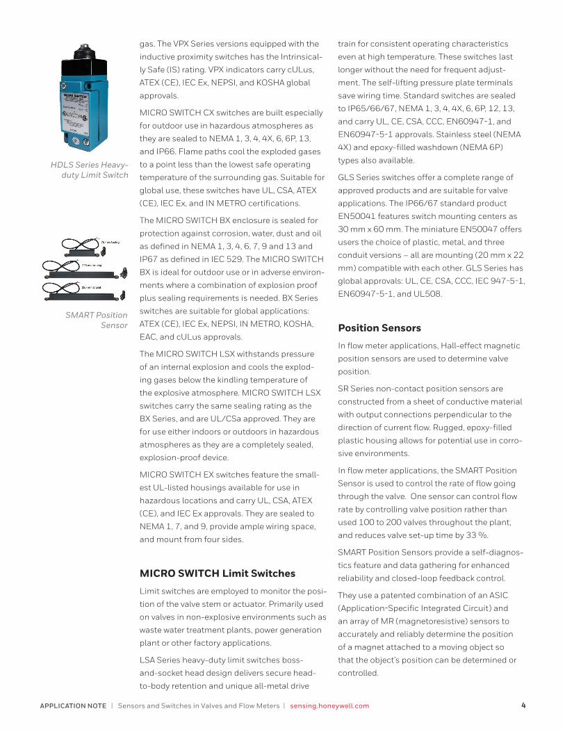
HDLS Series Heavy-duty Limit Switch
SMART Position Sensor
train for consistent operating characteristics
even at high temperature. These switches last
longer without the need for frequent adjust-
ment. The self-lifting pressure plate terminals
save wiring time. Standard switches are sealed
to IP65/66/67, NEMA 1, 3, 4, 4X, 6, 6P, 12, 13,
and carry UL, CE, CSA, CCC, EN60947-1, and
EN60947-5-1 approvals. Stainless steel (NEMA
4X) and epoxy-filled washdown (NEMA 6P)
types also available.
GLS Series switches offer a complete range of
approved products and are suitable for valve
applications. The IP66/67 standard product
EN50041 features switch mounting centers as
30 mm x 60 mm. The miniature EN50047 offers
users the choice of plastic, metal, and three
conduit versions – all are mounting (20 mm x 22
mm) compatible with each other. GLS Series has
global approvals: UL, CE, CSA, CCC, IEC 947-5-1,
EN60947-5-1, and UL508.
Position Sensors
In flow meter applications, Hall-effect magnetic
position sensors are used to determine valve
position.
SR Series non-contact position sensors are
constructed from a sheet of conductive material
with output connections perpendicular to the
direction of current flow. Rugged, epoxy-filled
plastic housing allows for potential use in corro-
sive environments.
In flow meter applications, the SMART Position
Sensor is used to control the rate of flow going
through the valve. One sensor can control flow
rate by controlling valve position rather than
used 100 to 200 valves throughout the plant,
and reduces valve set-up time by 33 %.
SMART Position Sensors provide a self-diagnos-
tics feature and data gathering for enhanced
reliability and closed-loop feedback control.
They use a patented combination of an ASIC
(Application-Specific Integrated Circuit) and
an array of MR (magnetoresistive) sensors to
accurately and reliably determine the position
of a magnet attached to a moving object so
that the object’s position can be determined or
controlled.
For more informationTo learn more about Honeywell’s
sensing and switching products,
call 1.800.537.6945 , visit sensing.honeywell.com,
or e-mail inquiries to [email protected]
Honeywell Sensing and Internet of Things 9680 Old Bailes Road
Fort Mill, SC 29707
www.honeywell.com000697-4-EN | 4 | 2/17© 2017 Honeywell International Inc.
Warranty/RemedyHoneywell warrants goods of its manufacture as being free of defective materials and faulty workmanship. Honeywell’s standard product warranty applies unless agreed to otherwise by Honeywell in writing; please refer to your order acknowl-edgment or consult your local sales office for specific war-ranty details. If warranted goods are returned to Honeywell during the period of coverage, Honeywell will repair or replace, at its option, without charge those items that Honeywell, in its sole discretion, finds defective. The foregoing is buyer’s sole remedy and is in lieu of all other warranties, expressed or implied, including those of merchantability and fitness for a particular purpose. In no event shall Honeywell be liable for consequential, special, or indirect damages.
While Honeywell may provide application assistance person-ally, through our literature and the Honeywell web site, it is customer’s sole responsibility to determine the suitability of the product in the application.
Specifications may change without notice. The information we supply is believed to be accurate and reliable as of this writing. However, Honeywell assumes no responsibility for its
use.
mWARNINGIMPROPER INSTALLATION• Consult with local safety agencies and their
requirements when designing a machine control link, interface and all control elements that affect safety.
• Strictly adhere to all installation instructions.Failure to comply with these instructions could result in death or serious injury.
The MR array measures the output of the MR sensors mount-
ed along the magnet’s direction of travel. The output and the
MR sensor sequence determine the nearest pair of MR sen-
sors to the center of the magnet location. The output of these
two MR sensors is then used to determine the position of the
magnet between them.
With this sensor, Honeywell has utilized MR technology
through the ASIC at a level never before accomplished.