Embed Size (px)
Citation preview

Shock and Vibration 11 (2004) 173–186 173IOS Press
Semi-active friction damping of large spacetruss structures
L. Gaul∗, H. Albrecht and J. WirnitzerInstitute A of Mechanics, University Stuttgart, Germany
The authors dedicate this paper to the memory of Professor Bruno Piombo.We commemorate him as a vital contributor to our science. From the experience of sharing conferences andworkshops with Bruno since many years, learning from his expertise and appreciating his advice, the first authormourns the loss of a good friend whose works and words will be kept in our minds and hearts.
Abstract. The present approach for vibration suppression of flexible structures is based on friction damping in semi-active joints.At optimal locations conventional rigid connections of a large truss structure are replaced by semi-active friction joints. Twodifferent concepts for the control of the normal forces in the friction interfaces are implemented. In the first approach eachsemi-active joint has its own local feedback controller, whereas the second concept uses a global, clipped-optimal controller.Simulation results of a 10-bay truss structure show the potential of the proposed semi-active concept.
1. Introduction
Large space structures (LSS) are commonly designed as very flexible and lightweight truss structures of bigsize. Due to their small damping and the stringent positioning accuracy, many missions involving antennas oroptical interferometers require vibration suppression. Numerous works have been published on active vibrationsuppression. Usually piezoelectric stacks are used as devices for actuators because of their light weight, high forceand minimum power consumption. Although an active approach is very attractive, actively controlled systemsmay cause spillover instability. Passive approaches for damping enhancement involving visco-elastic materials orpreloaded backlashes [20] may be desirable because of their simplicity and low cost. The present approach is basedon friction damping in the joint connections of a truss structure [7]. Dry friction caused by slip in the interface ofconnected parts turns out to provide a significant amount of energy dissipation. The original truss nodes are modifiedsuch that relative slip between the truss member’s end connector and the truss node is allowed.
However, passive approaches for vibration suppression are by far not as effective as active ones. Passive frictiondamping has several disadvantages. When the amplitude of vibration decreases below a certain level sticking occursand energy is no longer dissipated. In addition, if the stiction force is quite high the connected parts can stick andthus static shape accuracy cannot be assured. To overcome these drawbacks, the friction force in the joint connectionis controlled by varying the normal force in the contact interface using a piezoelectric stack [9]. Since a passivedevice is actively controlled, this approach is called semi-active. The resulting semi-active vibration suppressionsystem is always stable, at least in the Lyapunov sense, because of the dissipative nature of friction. Another appealof semi-active control is that performance levels of active control can be achieved with a fraction of input power.Furthermore, this concept can easily be employed without significantly increasing the structural weight.
The paper is structured as follows. It starts with the numerical model of the adaptive structure consisting of the trussstructure which is considered as a linear subsystem and the nonlinear semi-active joints which exert state-dependent
∗Corresponding author. E-mail: [email protected].
ISSN 1070-9622/04/$17.00 2004 – IOS Press and the authors. All rights reserved

174 L. Gaul et al. / Semi-active friction damping of large space truss structures
Fig. 1. Truss structure.
truss node
rod
end connector
Fig. 2. Meroform components.
friction forces on the linear subsystem. The parameters of the nonlinear friction model must be identified frommeasurements conducted with an isolated joint. Based on the open-loop state space model of the linear subsystem,modal reduction is performed using controllability and observability gramians. To improve the fidelity of the reducedmodel for lower frequencies, the modal subspace is augmented with Krylov vectors.
At optimal locations conventional connections are replaced by semi-active friction joints and two different controlconcepts for the semi-active vibration suppression are introduced: local feedback control and clipped-optimalcontrol. The simulation results for a 10-bay truss structure presented at the end reveal the potential of the presentedsemi-active approach.
2. Adaptive truss structure
The 10-bay truss structure depicted in Fig. 1 is made of Meroform-M12 construction system consisting ofaluminium tubes connected by steel nodes. The Meroform components are shown in more detail in Fig. 2. Each tubehas a 22 mm outer diameter and is fitted with a screw end connector. The horizontal and vertical distance betweenthe center of the truss nodes is 1 m. In accordance with the Shuttle Radar Topography Mission (SRTM)1 where asimilar truss structure has been used as a cantilever to carry one of the two radar equipments, the mast is clamped atone end. At the free end a mass of 0.5 kg is attached to each of the five truss nodes.
For the implementation of the semi-active damping approach a modified joint connection has been designed,which allows relative motion between the end connector of a truss member and the truss node with the remainingmembers attached to it. The rigid Meroform nodes can be replaced by this adaptive joint. As shown in Fig. 3, two
1For details visit the websites http://www.jpl.nasa.gov/srtm/ and http://www.aec-able.com/corporate/srtm.htm.

L. Gaul et al. / Semi-active friction damping of large space truss structures 175
x
y
z
Type B
Type A
friction element
end connector
Fig. 3. Types of joints.
x y
z
preload
friction elementfrictioninterfaces
PZT-stackactuator
load cell
Fig. 4. Adaptive joint (type B).
types of joints are considered, each allowing relative motion in one particular degree-of-freedom. It is the relativedisplacement along the longitudinal axis of the connected rod, affecting the extensional stiffness of the connection(type A), and the relative rotation about an axis perpendicular to the longitudinal axis, affecting the bending stiffnesof the connection (type B).
A sketch of the rotational prototype (type B) is shown in Fig. 4. The semi-active joint employs the dissipativecharacter of dry friction caused by interfacial slip in the contact area.2 By applying voltage to the piezoelectricalstack actuator, the pressure in the contact area can be altered. The normal force is approximately proportional to theapplied voltage. The preload of the stack can be adjusted by a screw.
2L. Gaul: German Patent “Smart Joint”, Number 19702518 C2 (1997).
176 L. Gaul et al. / Semi-active friction damping of large space truss structures
macro-slip
−2 −1 0 1 2x 10
−4
−0.8
−0.4
0
0.4
0.8
relative angle [rad]
M R
[Nm]
micro-slip
−8 −4 0 4 8x 10
−7
−0.04
−0.02
0
0.02
0.04
relative angle [rad]
M R
[Nm]
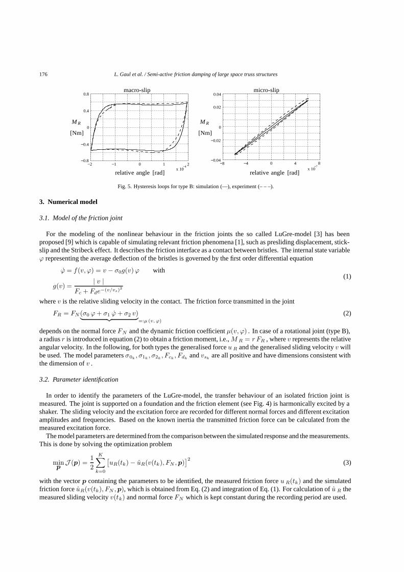
Fig. 5. Hysteresis loops for type B: simulation (—), experiment (– – –).
3. Numerical model
3.1. Model of the friction joint
For the modeling of the nonlinear behaviour in the friction joints the so called LuGre-model [3] has beenproposed [9] which is capable of simulating relevant friction phenomena [1], such as presliding displacement, stick-slip and the Stribeck effect. It describes the friction interface as a contact between bristles. The internal state variableϕ representing the average deflection of the bristles is governed by the first order differential equation
ϕ = f(v, ϕ) = v − σ0g(v)ϕ with(1)
g(v) =| v |
Fc + Fde−(v/vs)2
wherev is the relative sliding velocity in the contact. The friction force transmitted in the joint
FR = FN (σ0 ϕ + σ1 ϕ + σ2 v)︸ ︷︷ ︸=:µ (v, ϕ)
(2)
depends on the normal forceFN and the dynamic friction coefficientµ(v, ϕ) . In case of a rotational joint (type B),a radiusr is introduced in equation (2) to obtain a friction moment, i.e.,M R = r FR , wherev represents the relativeangular velocity. In the following, for both types the generalised forceu R and the generalised sliding velocityv willbe used. The model parametersσ0k
, σ1k, σ2k
, Fck, Fdk
andvskare all positive and have dimensions consistent with
the dimension ofv .
3.2. Parameter identification
In order to identify the parameters of the LuGre-model, the transfer behaviour of an isolated friction joint ismeasured. The joint is supported on a foundation and the friction element (see Fig. 4) is harmonically excited by ashaker. The sliding velocity and the excitation force are recorded for different normal forces and different excitationamplitudes and frequencies. Based on the known inertia the transmitted friction force can be calculated from themeasured excitation force.
The model parameters are determined from the comparison between the simulated response and the measurements.This is done by solving the optimization problem
minp
J (p) =12
K∑k=0
[uR(tk) − uR(v(tk), FN ,p)
]2(3)
with the vectorp containing the parameters to be identified, the measured friction forceu R(tk) and the simulatedfriction forceuR(v(tk), FN ,p), which is obtained from Eq. (2) and integration of Eq. (1). For calculation ofu R themeasured sliding velocityv(tk) and normal forceFN which is kept constant during the recording period are used.

L. Gaul et al. / Semi-active friction damping of large space truss structures 177
Table 1Identified friction parameters
Typ σ0 σ1 σ2 Fc Fd vs rA 1.42 · 105 1/m 0.02 s/m 0.01 s/m 0.61 0.14 0.01m/s –B 6.5 · 104 1/rad 0.02 s/rad 0.01 s/rad 0.49 0.08 0.02 rad/s 0.011 m
From the results of a fuzzy sensitivity analysis [13] it is known, that the individual parameters are responsiblefor different behaviour characteristics. Micro-slip behaviour is mostly affected by the parametersp 1 = [σ0 σ1].During macro-slip, where sliding in the entire contact area occurs, especially the parametersp 2 = [Fc Fd vs σ2]are of importance. Macro-slip and micro-slip behaviour can be generated by choosing an appropriate combinationof excitation amplitude and normal force which has an influence on the break-away force.
To efficiently solve the optimization problem in Eq. (3), the identification is carried out in two steps. First, theparametersp1 are identified from responses measured during micro-slip regime. The remaining parametersp 2 areobtained from measurements where the joint is operated in stick-slip behaviour. For both optimizations, data fromseveral measurements with different excitations and normal forces are used. Because of the nonlinear objectivefunction Eq. (3) a gradient-based optimization algorithm will only give local minima. Therefore, it is important tostart the optimization with reasonable initial values forp1 andp2.
The identified parameters are listed in Table 1 for both types of the joint. The present joint design turned out tohave quite small parametersσ1 undσ2 which have almost no influence on the dynamical behaviour. A fact that isconfirmed by the results of the fuzzy sensitivity analysis [13]. Therefore, it is hard to identify their actual values. Asan example, one of the measured hysteresis loops for type B is compared to the predicted loop in Fig. 5.
3.3. FE-model of the truss structure
The FE discretization of the truss connections is depicted in Fig. 6. All tubes and end connectors are discretizedby cubic Euler-Bernoulli beams with two nodes, each having six degrees of freedom. The Meroform nodes areconsidered as perfectly rigid and the rigid portions are modelled by geometric constraintsum = Snmun betweenthe tied dofsum and the independent dofsun. The mass and inertia of the Meroform connections are lumped atthe centers of each truss node. The kinematics of the friction joints are described by constraint matrices, as well,which couple the degrees of freedom of the corresponding nodes according to the type of joint. By assembling allconstraint matricesSnm into matrixS, all dependent degrees of freedom of the original finite element model withmass matrixM , damping matrixD, stiffness matrixK and the displacement vectorz can be eliminated as follows
STMS ¨z + ST DS ˙z + ST KSz(4)
= ST E uR (v,ϕ) + ST Fw .
The resulting system of differential equations is given by
Mz +Dz +Kz = EuR (v,ϕ) + Fw (5)
with the vectorz containing only the independent generalised displacementsz j (j = 1, . . . , N ). The friction forcesuR(v, ϕ) acting in the friction joints depend on the sliding velocitiesv = E T z and the bristle deflectionsϕ. Vectorw represents disturbances.
Using the modal trasformation
z(t) = Φη(t) (6)
with the modal matrixΦ = [φ1, . . . ,φn] (including n < N ‘significant’ eigenmodesφi) obtained from theundamped eigenvalue problem
Kφi = ω2iMφi , i = 1, . . . , n (7)
and assuming modal damping, Eq. (5) can be transformed to a set of differential equations
η + Ξη + Ωη = ΦTEuR(v,ϕ) + ΦTFw (8)

178 L. Gaul et al. / Semi-active friction damping of large space truss structures
truss noderigid connection
end connector
truss members
Fig. 6. FE discretization.
No EMA FEM error [%] MAC
1 4.49 4.495 0.18 0.79
2 4.60 4.595 0.19 0.88
3 20.65 20.60 0.24 0.97
4 22.07 22.25 0.82 0.95
5 23.61 23.76 0.64 0.93
7 24.72 25.08 1.46 0.93
8 43.47 43.73 0.60 0.95
12 46.83 46.90 0.15 0.98
17 49.45 49.52 0.14 0.72
Fig. 7. Eigenfrequencies in [Hz].
with the matricesΩ = diag (ω2i ), Ξ = diag (2ξi ωi) and the vectorη of modal coordinatesη i. The eigenfrequency
and the modal damping coefficient of thei-th mode is denoted byω i andξi, respectively.The sliding velocitiesv and the measured statesy, which in chapters 4.3 and 6 will be the deflections of the tip
of the mast, are given by
v =ET Φ η (9)
y = V Φη +WΦη . (10)
It should be pointed out that the transformation matrix in Eq. (6) is composed of eigenvectors of the underlyinglinear undamped system. That means, the nonlinear state-dependent term in the excitation vectoru R is neglectedand a truss structure with frictionless joint connections is considered, i.e.FNj = 0. That way, the structure ofthe linear subsystem can fully be exployed for the upcoming model reduction. Such an approach is often used forsystems with local nonlinearities [16].
Since not all the parameters of the FE model are known a priori, they have to be identified by means of ModalUpdating [6] using eigenfrequencies and mode shapes obtained from an Experimental Modal Analysis (EMA) whichhas been performed on the structure. The unknown parameters particularly are the axial, bending and torsionalstiffness of the end connectors. Furthermore, the material properties of the aluminum members are not exactlyknown. Dimensions and masses of the components however are considered as given.
The eigenfrequencies calculated with the updated FE model are compared to the measured values in Table 7. Thecorresponding MAC values [6] of the mode shapes are listed as well. Note that only those modes are listed whosemode shapes could clearly be identified by the EMA. The extracted modal damping ratios0.05% ξ i 0.5%confirm that the present strutcture indeed is a weakly damped system. For the upcoming simulationsξ i = 0.1% willbe used for all modesi = 1, . . . , n.

L. Gaul et al. / Semi-active friction damping of large space truss structures 179
3.4. Model of the adaptive structure
By defining the state vector of the linear subsystem as
x =[xT
1 , . . . , xTn
]Twith xi =
[ηi
ωiηi
](11)
where the statexi represents thei-th mode, the state space form of the friction damped truss structure is given by[xϕ
]=[
Axf(v,ϕ)
]+[B0
]uR(v,ϕ) +
[H0
]w . (12)
The system matrixA as well as the matricesB andH can easily be deduced from Eq. (5) by taking the definitionof the state vectorx into account. The internal state variablesϕ j (j = 1, . . . , l) of the l semi-active friction jointsare arranged inϕ, the corresponding differential Eq. (1) inf (v,ϕ). The sliding velocities are given byv = B Tx.The actuator forcesuR are defined by Eq. (2) asuRj = FNj µj(vj , ϕj) where the normal forcesFNj represent thecontroller output.
4. Model reduction
Because of the high order of the system Eq. (12), a model reduction is required to obtain a low order model for thecontrol design. This is done by significantly reducing the order of the linear subsystem and keeping the nonlinearpart unchanged. Thus, the linear subsystem[
xd
xnd
]=[Ad 00 And
] [xd
xnd
]+[Bd
Bnd
]u+
[Hd
Hnd
]w (13)
v =[BT
d BTnd
] [ xd
xnd
](14)
y =[Cd Cnd
] [ xd
xnd
](15)
is considered in the following. It is partitioned into dominant statesxd which will be kept in the reduced model, andstatesxnd which will be removed. In the following considerations, the nonlinear friction forcesu R are neglectedand the vectoru represents external (state-independent) actuator forces.
4.1. Balanced reduction
The determination of dominant modesxdi is based on balanced reduction using controllability and observabilitygramians corresponding to the different inputs (u,w) and outputs (v, y) of the system. For an asymptotically stablesystem, the controllability gramianW c and observability gramianW o are symmetric and positive definite matriceswhich can be computed from the steady-state Lyapunov equations [19]
AW c +W cAT +BBT = 0 and(16)
ATW o +W oA+CTC = 0 .
Due to the particular form of the state space model with modal coordinates, Eq. (16) can be solved in closedform [11]. For structures with small damping and well separated eigenfrequencies3 the gramians tend to diagonalmatrices
3Even for truss structures with their quite high modal density, this approximation is valid as long as the damping ratios are small, i.e.,ξi 1 [11,12].

180 L. Gaul et al. / Semi-active friction damping of large space truss structures
act. 3
act. 2
act. 1 xz
y
mass (0.5 kg)
excitation
Fig. 8. Example: Structure with semi-active joints.
W c(o) = diag
(w
c(o)i 00 w
c(o)i
)with
(17)
wci = ui
eieTi
4ξiωi, wo
i =ω2
iwTi wi + vT
i vi
4ξiω3i
wherei = 1, . . . , n. The vectorei is thei-th row of ΦTE, vectorsvi andwi correspond to thei-th column ofV Φ andWΦ, respectively. Thei-th diagonal elementw c
i (woi ) is a quantitative measure for the controllability
(observability) of thei-th statexi = [ηi, ωiηi]T which represents thei-th mode.To idenfity modes which are relevant for the transfer behaviour of the input/output path fromu R to v, one has to
check the corresponding Hankel singular values [12]
γuvi =√
wcui
wovi
=eie
Ti
4ξiωi(18)
defined by means of the eigenvalues of the controllability and observability gramians for the inputu and outputv,i.e., wc
uiandwo
virespectively. Modes with large Hankel singular valuesγuvi should be included into the reduced
model in order to guarantee a good approximation of the original system. Those modes will mainly be excited bythe friction forces. And they will contribute to the sliding velocitiesv occuring in the friction joints, as well.
In addition, all modes which have an impact on the system measurementsy need to be added to the reducedmodel. They are selected according to the eigenvaluesw o
yiof the observability gramian corresponding to the output
y. When the disturbance input matrixH is known, it can be taken into account as well.
4.2. Krylov vectors
After the dominant states are choosen, the reduced model of the linear subsystem is given by
xd =Adxd +BduR(v,ϕ) +Hdw (19)
v =BTd xd = ET Φdηd (20)
y = Cdxd = V Φdηd +WΦdηd . (21)
Now, focus on the input/output path fromuR to v which is the most critical since the prediction of the localnonlinearities is affected by the approximation quality of this path. As a result of neglecting the partB T
ndxnd
in Eq. (20), the approximated sliding velocityv is erroneous. This has a negative effect on the prediction of theresulting friction forcesuR(v,ϕ). The approximation error would amplify when simulating the closed-loop system.Therefore, it is important to somehow compensate for the deleted modes. For this purpose the transfer matrixG uv(s)fromu to v
Guv(s) = BT (sI −A)−1B = BTd (sId −Ad)−1Bd︸ ︷︷ ︸=:Guv
d (s)
+Guvnd(s) (22)
is considered. The termGuvnd corresponds to the neglectednnd = N−nd modes. The coefficientsHk = Hdk
+Hndk
of a Taylor series arounds0 = 0

L. Gaul et al. / Semi-active friction damping of large space truss structures 181
0
0.05
0.1
0 100 200 300 400 500 6000
0.1
0.2
0 100 200 300 400 500 600
mode mode
type B type A
Fig. 9. Eigenvalueswcui
.
Guv(s) =Nk∑k=0
(−1)k+1BTA−k−1B︸ ︷︷ ︸=:Hk(0)
sk =Nk∑k=0
(Hdk
(0) + Hndk(0))sk (23)
are the so called ‘low order moments’ which are used in ‘moment matching methods’ for model reduction purposes [4].Considering thej-th friction joint, the first (k = 0) correction termHnd0 for the second order system in Eq. (5) isgiven by
Hnd0 = H0 −Hd0 = eTj
(K−1ej − ΦdΩ−1
d ΦTd ej
)= eT
j
(I − ΦdΦT
dM)K−1ej (24)
when no damping is assumed4, ej being thej-th column of the matrixE. Hnd0 represents the difference betweenthe static deformationK−1ej caused by an unit load acting in thej-th joint and the deformationΦ dΩ−1
d ΦTd ej
which results from the mode superposition of the modesΦd. By taking further coefficientsHndkinto account, the
following recursive formula (Arnoldi process)
ψ∗k = K−1Mψk−1ψ
∗∗k =
(I − Σk−1ΣT
k−1M)ψ∗
kψk = ψ∗∗k
(ψ∗∗T
k Mψ∗∗k
)− 12
(25)
for the calculation of so called Krylov vectors [2] can be derived. The starting vector is choosen asψ 0 = K−1ej .The matrixΣk = [Φd ψ1 . . . ψk−1] contains not only the eigenvectors ofΦd but the new generated vectorsψk−1 (k > 1) as well. Thus, the bracket term in Eqs (26) and (27) constitute an orthonormalization with respectto the mass matrix. By generatingK vectors for each friction jointj, a total number ofl · K Krylov vectors isobtained. Since the columns ofΨ = [ψ1 . . . ψlK ] are not orthogonal with respect to the stiffness matrix, a singularvalue decomposition (SVD)
ΨTKΨ = T ΩT whereΩ = diag (ω2m) , m = 1, . . . , lK (26)
is used to yield vectorsΨ = ΨT which also diagonalize the stiffness matrix.When the transformation
z(t) = [Φd Ψ][ηd
η
]withΨ = [ψ1 . . . ψlK ] andη = [η1 . . . ηlK ]T , (27)
is applied instead of Eq. (16), the reduced model Eq. (19) is extended by the additional rows
¨ηm + 2ξm ωm˙ηm + ω2
m ηm = ψT
mEu∗R(v∗,ϕ) + ψ
T
mFw , m = 1, . . . , lK (28)
And the expression for the approximated sliding velocity is
v∗ = ET Φdηd +EΨ ˙η . (29)
The last expression in Eq. (31) can be seen as a correction term which reduces the approximation error for lowfrequencies by compensating for the neglected modes of the original system. This also improves the approximatedfriction forcesu∗
R.
4Similar expressions can be given for damped second order systems [4]

182 L. Gaul et al. / Semi-active friction damping of large space truss structures
1.40 0.2 0.4 0.6 0.8 1.2
−2
0
2
t [s]
uR 1
[Nm]
uR 1 uR 1 uR 1
1
*
Fig. 10. Approximation of the friction momentuR1 .
4.3. Example
As an example, the proposed reduction method is now applied to the 10-bay truss structure illustrated in Fig. 8.The displacements iny- andz-direction at the sensor location are used as measurementsy. The disturbancew is atriangular pulse iny- andz-direction which acts as a force at the mast tip as shown in Fig. 8.
For the present example a configuration with three friction joints (two of type A and one of type B) is used.Figure 9 shows the firstn = 600 eigenvalueswc
i of the controllability gramian for the rotational joint (type B) andfor one of the translational joints (type A). As can be seen, the frictional forces caused by type A mainly affect thelowest modes whereas those caused by type B also excites higher modes. Therefore, only the friction joint of type B(actuator 1) will be considered as ‘active’, in order to point out the effect of the correction termE Ψ ˙η in Eq. (31)on the approximation of the sliding angular velocityv 1 and the friction momentuR1 . In the other two joints oftype A no friction forces are transmitted and they are regarded as frictionless joint connections with zero normalforce (FN2,3 = 0). The reason for using those ‘inactive’ joints anyway is the resulting local stiffness reduction whichis necessary for a significant effect of the rotational joint to occur.
Using the procedure from Section 4.1nd = 60 dominant modes are selected from the firstn = 100. Allhigher modes are not included in the reduced model despite their large eigenvalues5. For a constant normal forceFN1 = 400 N, the friction momentuR1 of the reduced system given by Eq. (19) is plotted in Fig. 10 together withthe friction moment obtained from the original system Eq. (5). It is obvious that the approximation of the actualfriction moment is quite bad.
However, augmenting the modal subspace spanned by the eigenvectorsφ diwith just two Krylov vectorsψ1,2
(l = 1 , k = 1, 2) improves the low frequency approximation remarkably, as can be seen from the time signal ofu∗
R1in Fig. 10.
5. Semi-active control
In the following, two different control approaches are proposed. In the first approach each semi-active frictionjoint has its own local feedback controller. The second concept uses one global clipped-optimal controller.
5.1. Local feedback control
Several semi-active control laws for friction dampers have been derived [18]. A bang-bang controller can bedesigned by inspection of the time derivative of the Lyapunov function representing the system energy. For the
5The numbersn andnd are determined quite arbitrarily just to point out the effect of the correction term. An optimization of the ratio ofndto the number of Krylov vectors is not considered in this paper.

L. Gaul et al. / Semi-active friction damping of large space truss structures 183
xz
ysemi-active joints
sensor
excitation
Fig. 11. Structure with three semi-active joints at optimal positions.
LuGre friction model defined by Eqs (2) and (1), one arrives at the feedback law
FNj =
FmaxNj
, µj vj εj
FminNj
+ (FmaxNj
/εj)µj vj , 0 < µj vj < εj
FminNj
, µj vj 0(30)
which maximizes the energy dissipation in the adaptive joint by avoiding sticking. A boundary layerε j hasbeen introduced to avoid chattering (quasi-sticking) which degrates the energy dissipation. The dynamic frictioncoefficientµj is obtained from the relation
µj(t) =uRj (t − ∆t)FNj (t − ∆t)
(31)
where1/∆t is the sampling rate of the controller.It is assumed that besides the sliding velocitiesv the friction forcesuR can be measured, as well. Otherwise they
have to be estimated using a simple integrator model as proposed by [14] or the dynamic friction coefficientsµ j
have to be observed using an extended Kalman filter [8,10].For an efficient vibration suppression, the control parametersε j of the SISO-controller are optimized [21] with
respect to the system energy given by
E(te) =
te∫0
(xTx
)dt . (32)
5.2. Clipped-optimal control
For the second approach a so called clipped-optimal controller is used [5]. First, a LQG controller [17] is designedassuming an active control system and neglecting the actuator dynamics. The optimal actuator forces
ud = −K x (33)
are defined by the gain matrixK, which is obtained as a solution of the algebraic Riccati equation [17] and the statevectorx is estimated by means of a Kalman filter [15].
The actuator forcesud cannot directly be applied to the structure, they have to be generated by the semi-activefriction dampers. This is achieved by controlling the normal force in each friction joint using the following localbang-bang controller
FNj = FminNj
+ FmaxNj
H[ej uRj
],
(34)Fmin
Nj FNj Fmax
Nj
which updates the normal forceFNj in thej-th friction force depending on the differencee j = udj − uRj betweenthe desired actuator forceudj and the actual friction forceuRj . To avoid unwanted bang-bang behavior due to theHeavyside functionH(·), a boundary layer can be introduced as has been done for the SISO controller defined byEq. (32). In the following, the proposed controller is refered to as cLQG controller.
The approximation of the desired actuator forces is limited because of the dissipativity constraint and the bound-edness of the friction force. If the measurement of the actual friction forces turns out to be difficult, the Kalmanestimator can be extended by an integrator model [14] to estimate the friction forces, as well.

184 L. Gaul et al. / Semi-active friction damping of large space truss structures
t [s]
E
[Nm]
SISO
F maxN
F minN
0
0.1
0.2
0.3
Fig. 12. System energy.
0 0.20
0.1
0.2
0.3
0.4 0.6 0.8 1.0
t [s]
E
[Nm]
SISO
cLQG
LQG
Fig. 13. System energy.
0
4
0 0.2 0.4 0.6 0.8 1.0
2
t [s]
y
[mm] SISOcLQG
LQG
0
4
0 0.2 0.4 0.6 0.8 1.0
2
4
2
t [s]
z
[mm]
SISO
cLQGLQG
Fig. 14. Deflection of the mast tip:y-direction (left),z-direction (right).
6. Simulation results
The simulation results in this section will show the potential of the proposed semi-active approach to vibrationsuppression. The boundary conditions and disturbance (impulse force with an amplitude of200 N over a time periodof 40 ms) are the same as described in the previous Section 4.3. Three semi-active friction joints are placed in orderto affect the lower modes of the structure. The optimal locations for a specific mode are determined by consideringthe strain energies in the end connectors which occur when the structure is deformed according to the mode shape.Since the focus has been put on the lower modes, all semi-active joints are of type A. The replaced truss nodes andthe corresponding members which are adaptively connected to them are marked in Fig. 11. It should be noted thatif the vibration of the structure is dominated by modes not considered in the optimization of the joints’ placement,their ability to enhance the damping of the vibration decreases accordingly.
The numerical model is reduced to24 states using the proposed reduction method. The24 states represent9modes and3 additional ‘correction modes’ (Krylov vectors) generated for each friction joint.
Figure 12 compares the decay of the system energyE (defined by Eq. (34)) for the structure with passive andsemi-active friction joints. A passive joint has a constant normal force which is set to eitherF min
N or FmaxN . For
the semi-active joints the control law Eq. (32) with optimized control parameterε j is used. It should be noted thatduring the excitation time period, the normal forces are set toF max
N in order to enable a comparison of the different

L. Gaul et al. / Semi-active friction damping of large space truss structures 185
concepts. As can be seen, the damping can significantly be enhanced by controlling the normal forces in the frictionjoints. With a constant maximal normal force good vibration suppression is achieved at the beginning. However,as the vibration amplitude decreases sticking occurs and no energy is dissipated. Only the small structural dampingreduces the vibrations.
The performance of the cLQG controller is shown in Fig. 13 together with the SISO controller. Furthermore, theresponse of a fully active system where the optimal actuator forcesud are provided by the LQG controller (Eq. (35))are directly applied to the structure. The corresponding tip deflections iny- andz-direction are given in Fig. 14.
When considering the system energy, the cLQG controller seems to perform only slightly better than the three SISOcontrollers. The advantage of the cLQG controller becomes more obvious when the tip deflections are compared(Fig. 14). In order to see how a fully active system would perform, the corresponding plots are included in Figures 13and 14 as well. As can be seen, the suppression of the tip deflections provided by the LQG controller (activesystem) is only slightly better when compared to the cLQG controller (semi-active system), wheras the advantageof the cLQG controller over the three SISO controllers is significant. However, it is important to point out that thesemi-active approach requires only a fraction of the control power of the active system.
7. Conclusions
The present semi-active approach to vibration suppression of large space truss structures is based on controlledenergy dissipation in friction joints. A numerical model of the adaptive structure is presented, including the nonlineardynamics of the friction joints. The finite element model of the truss structure is updated by using data from anExperimental Modal Analysis. And the parameters of the friction model are identified from measurements on anisolated friction joint. To obtain a low order model a reduction method is proposed which is a combination ofbalanced reduction and matching moments method. A numerical example illustrates the approximation quality ofthe reduced model. Two different control approaches for semi-active damping using friction joints are introduced.Finally, the simulation results of the truss structure with three semi-active friction joints demonstrate the efficiencyof the present vibration suppression approach.
Acknowledgements
The authors gratefully acknowledge the funding of this research by the DFG (Deutsche Forschungsgemeinschaft)under grant GA209/24 “Adaptive control of mechanical joints in lightweight structures”.
References
[1] B. Armstrong-Helouvry, P. Dupont and C.D. Wit, A survey of models, analysis tools and compensation methods for the control of machineswith friction, Automatica 30(7) (1994), 1083–1138.
[2] Z. Bai, Krylov subspace techniques for reduced-order modeling of large-scale dynamical systems,Journal of Applied Numerical Mathe-matics 43 (2002), 9–44.
[3] C. Canudas de Wit, H. Olsson, K.J. Ïstrom and P. Lischinsky, A new model for control of systems with friction,IEEE Transactions onAutomatic Control 40(3) (1995), 419–425.
[4] R.R. Craig Jr. and T.-J. Su, Model reduction and control of flexible structures using krylov vectors,Journal of Guidance and Control 14(2)(1991), 260–267.
[5] S.J. Dyke et al., Lyapunov design of damping controllers,Archive of Applied Mechanics 5 (1996), 565–575.[6] M.I. Friswell and J.E. Mottershead,Finite Element Model Updating in Structural Dynamics, Kluwer Academic Publishers, Dordrecht,
1995.[7] L. Gaul, H. Albrecht and J. Wirnitzer, Damping of structural vibrations using adaptive joint connections and neural control, in:CISM
Courses and Lectures: Smart Structures, A. Suleman, ed., No. 429, 2001, pp. 86–97, Udine, Italy.[8] L. Gaul and R. Nitsche, Friction control for vibration suppression,Mechanical Systems and Signal Processing 14(2) (2000), 139–150.[9] L. Gaul and R. Nitsche, The role of friction in mechanical joints,Applied Mechanics Reviews (ASME) 54(2) (2001), 93–106.
[10] L. Gaul and R. Nitsche, Lyapunov design of damping controllers,Archive of Applied Mechanics 72 (2003), 865–874.[11] W.K. Gawronski and J.-N. Juang, Model reduction for flexible structures,Control and Dynamic Systems: Advances in Theory and
Application 36 (1990), 143–222.

186 L. Gaul et al. / Semi-active friction damping of large space truss structures
[12] C.Z. Gregory Jr., Reduction of large flexible spacecraft models using internal balancing theory,Journal of Guidance and Control 7(6)(1984), 725–732.
[13] M. Hanss, S. Oexl and L. Gaul, Simulation and analysis of structural joint models with uncertainties, in:Proc. of the InternationalConference on Structural Dynamics Modeling – Test, Analysis, Correlation and Validation, (Madeira Island, Portugal), 2002, pp. 165–174.
[14] R. Hu and P.C. Muller, Position control of robots by nonlinearity estimation and compensation: Theory and experiements,Journal ofIntelligent and Robotic Systems 20 (1997), 195–209.
[15] R.E. Kalman and R. Bucy, New results in linear filtering and prediction,ASME Journal of Basic Engineering 83 (1961), 95–108.[16] A.R. Kukreti and H.I. Issa, Dynamic analysis of nonlinear structures by pseudo-normal mode superposition method,Computers &
Structures 19(4) (1984), 643–663.[17] H. Kwakernaak and R. Sivan,Linear Optimal Control Systems, Wiley, New York, 1972.[18] J.S. Lane, A.A. Ferri and B.S. Heck, Vibration control using semi-active friction damping, inFriction-induced vibration, chatter, squeal,
and chaos, ASME 49 (1992), 165–171.[19] B.C. Moore, Principal component analysis in linear systems: Controllability, observability, and model reduction,IEEE Transactions on
Automatic Control AC-26(1) (1981), 17–32.[20] J. Onoda, T. Sano and K. Minesugi, Passive damping of truss vibration using preloaded joint backlash,AIAA Journal 33(7) (1995),
1335–1341.[21] J. Wirnitzer, A. Kistner and L. Gaul, Optimal placement of semi-active joints in large space truss structures, in:SPIE Conference on Smart
Structures and Materials 2002: Damping and Isolation, G.S. Agnes, ed., No. 4697, (San Diego, USA), 2002, pp. 246–257.

International Journal of
AerospaceEngineeringHindawi Publishing Corporationhttp://www.hindawi.com Volume 2010
RoboticsJournal of
Hindawi Publishing Corporationhttp://www.hindawi.com Volume 2014
Hindawi Publishing Corporationhttp://www.hindawi.com Volume 2014
Active and Passive Electronic Components
Control Scienceand Engineering
Journal of
Hindawi Publishing Corporationhttp://www.hindawi.com Volume 2014
International Journal of
RotatingMachinery
Hindawi Publishing Corporationhttp://www.hindawi.com Volume 2014
Hindawi Publishing Corporation http://www.hindawi.com
Journal ofEngineeringVolume 2014
Submit your manuscripts athttp://www.hindawi.com
VLSI Design
Hindawi Publishing Corporationhttp://www.hindawi.com Volume 2014
Hindawi Publishing Corporationhttp://www.hindawi.com Volume 2014
Shock and Vibration
Hindawi Publishing Corporationhttp://www.hindawi.com Volume 2014
Civil EngineeringAdvances in
Acoustics and VibrationAdvances in
Hindawi Publishing Corporationhttp://www.hindawi.com Volume 2014
Hindawi Publishing Corporationhttp://www.hindawi.com Volume 2014
Electrical and Computer Engineering
Journal of
Advances inOptoElectronics
Hindawi Publishing Corporation http://www.hindawi.com
Volume 2014
The Scientific World JournalHindawi Publishing Corporation http://www.hindawi.com Volume 2014
SensorsJournal of
Hindawi Publishing Corporationhttp://www.hindawi.com Volume 2014
Modelling & Simulation in EngineeringHindawi Publishing Corporation http://www.hindawi.com Volume 2014
Hindawi Publishing Corporationhttp://www.hindawi.com Volume 2014
Chemical EngineeringInternational Journal of Antennas and
Propagation
International Journal of
Hindawi Publishing Corporationhttp://www.hindawi.com Volume 2014
Hindawi Publishing Corporationhttp://www.hindawi.com Volume 2014
Navigation and Observation
International Journal of
Hindawi Publishing Corporationhttp://www.hindawi.com Volume 2014
DistributedSensor Networks
International Journal of


![A Friction Control Strategy for Shock Isolationarticle.ijmea.org/pdf/10.11648.j.ijmea.20190703.12.pdf · damping element. Ismail and Ferguson [1] utilised dry friction to isolate](https://img.dokumen.tips/doc/110x75/5ead75c10aeb626e19654609/a-friction-control-strategy-for-shock-damping-element-ismail-and-ferguson-1-utilised.jpg)