Embed Size (px)
Citation preview

IOSR Journal of Mechanical and Civil Engineering (IOSR-JMCE) e-ISSN: 2278-1684,p-ISSN: 2320-334X, Volume 12, Issue 5 Ver. IV (Sep. - Oct. 2015), PP 69-81
www.iosrjournals.org
DOI: 10.9790/1684-12546981 www.iosrjournals.org 69 | Page
Experimental Study of the Effect of Rivets on Damping in Jointed
Structures
Rahul H. Hodgar1, Dr. Y.R Kharde
2
1(M.E Student, Department of Mechanical Engineering, Pravara Rural Engineering College, Loni,
Maharashtra, India) 2(Professor, Department of Mechanical Engineering, Pravara Rural Engineering College, Loni, Maharashtra ,
India)
Abstract : Riveted joints are often used to fabricate assembled structures in machine tools, automotive, trusses
and many such industries requiring high damping. The present work aims to study the mechanism of damping
and its FEA evaluation for jointed cantilever beam with number of equispaced connecting rivets resulting in
uniform pressure distribution at interfaces. Vibration attenuation in these structures can enhance the dynamic
stability significantly. A little amount of work has been reported till date on the damping capacity of riveted
structures. Using OROS Series (OR34 - 4 Channel) FFT analyzer experiments are performed on various
specimens. The damping ratio is calculated from FFT spectrum obtained from FFT Analyzer. It is established
that the damping capacity of structures jointed with connecting rivets can be improved substantially with an
increase in number of rivets maintaining uniform intensity of pressure distribution at the interfaces.
Keywords - Ansys 11.0, Built-up Structure, Damping Mechanism, Damping ratio (ξ), Riveted joints.
I. INTRODUCTION The study of damping and its importance in structures has become increasingly significant for
controlling the undesirable effects of vibration. Following are the requirements of modern technology, there has
been significant increase in demand to design, develop and fabricate machine tools, space structures, high speed
automobiles, etc. to meet the global demand. The manufacturer of such structures also requires high damping
capacity and stiffness with light weight for its effective use. Such requirements demanded and popularized the
use of welded, bolted and riveted layered beams as structural members with high damping capacity. In the
alternative, cast structures can be used, but unfortunately, these are more expensive to manufacture and as a
result, the development of welded, bolted and riveted multi-layered beam structures is becoming increasingly
common in such industries. Joints have a great potential for reducing the vibration levels of a structure and have
attracted the interest of many researchers. Many comprehensive review papers on joints and fasteners have
appeared in recent years. Although a lot of work has been carried out on the damping capacity of bolted
structures, but a little amount of work has been reported till date on the mechanism of damping in layered and
jointed riveted structures. Furthermore, the effect of the influencing parameters on the damping rate of such
structures is investigated and discussed in this study. Damping ratio, a measure of damping capacity of jointed
structures is determined by energy principle considering interface pressure at the interfaces of contacting layers.
Huge amount of work has been reported by Masuko et al. [2], Nishiwaki et al. [3], on damping capacity of such
structures assuming uniform pressure distribution at interfaces of jointed structures. B.K Nanda and Behera [8]
have established that energy dissipation in jointed structure take place due to micro-slip at the interfaces of
contacting layers. B.K Nanda [1] found that the damping increases with an increase in number of layers in
jointed structure due to an increase in interface friction layers which causes an increase in energy loss.
1.1 Riveted Joints
A rivet is a short cylindrical bar with a head at one end. This head is formed on the shank by upsetting
process in a machine called Riveting machine. The rivet is inserted in the holes of the parts being assembled as
shown in Fig.1.
There two methods of riveting:- hand riveting, machine riveting. In hand riveting a die is placed on the
protruding end of the shank. In machine riveting, the die is a part of hammer, which is operated by pneumatic,
hydraulic pressure.
1.1.1 Advantages of Riveted joints
1) Riveted joint are more reliable than welded joint in applications which are subjected to vibrations and impact
forces.

Experimental Study of the Effect of Rivets on Damping in Jointed Structures
DOI: 10.9790/1684-12546981 www.iosrjournals.org 70 | Page
2) Welded joints are restricted to steel parts. Riveted joints can be used for non-ferrous metals like aluminium
alloy, copper, brass or non-metals like asbestos or plastics
3) The heat required for welding causes warping and affects the structure of heat treated components. The parts
assembled by riveted joint are free from such thermal effects.
4) When the riveted joint is dismantled, the connected components are less damaged compared with those
welded joint.
1.1.2 Drawbacks of Riveted joints
1) The overall cost of riveted joint is more than that of welded joint due to increased metal consumption and
higher labour cost.
2) Riveted assemblies have more weight than welded assemblies due to strap plates and rivets.
1.1.3 Applications of Riveted joints
1) Riveted joints are used where it is necessary to avoid the thermal effects of welding.
2) Riveted joints are used where thin plates are to be assembled. They are popular especially for aircraft
structures where light structures made of aluminium alloys are to be fastened.
Fig.1: Ordinary forms of rivets after riveting
II. THEORETICAL ANALYSIS Most structural problems are studied based on the assumption that the structure to be analyzed is either
linear or nonlinear. In linear systems, the excitation and response are linearly related and their relationship is
given by a linear plot as shown in Fig.2. For many cases, this assumption is more often valid over certain
operating ranges. Working with linear models is easier from both an analytical and experimental point of view.
For a linear system, the principle of superposition holds which means that doubling the excitation will double
the levels of the response. For beams undergoing small displacements, linear beam theory is used to calculate
the natural frequencies, mode shapes and the response for a given excitation. It is very clear from Fig. that the
linear and nonlinear systems agree well at small values of excitation, while they deviate at higher levels. The
nonlinear beam theory is used for larger displacements where the superposition principle is not valid. The linear
vibration theory is used when the beam is vibrated at small amplitudes and lower modes of vibration. The
present investigation mainly focuses on the study of damping of jointed fixed beams at lower excitation levels
which can be considered as linear.
Fig.2: Comparison of Linear and nonlinear systems

Experimental Study of the Effect of Rivets on Damping in Jointed Structures
DOI: 10.9790/1684-12546981 www.iosrjournals.org 71 | Page
III. PROBLEM STATEMENT Various structures have been tested and the great potential for a friction joint to reduce vibration level
has been observed. The problems in utilizing a friction joint as a tool to control the vibration of a fabricated
structure have been as:
1) Fretting corrosion at joint interface
2) Loss of static stiffness of the structure
3) Difficulty in design and analysis due to problems of nonlinearity
4) The structures are highly subjected to vibration which leads to failure. Due to continuous vibration life of the
structure decreases. In order to avoid this type of failure a structure should be damped.
5) Damping capacity is higher in bolted joints and least in welded joints. Hence in order to overcome these
drawbacks a beam with riveted joints are used.
IV. OBJECTIVES OF THE WORK Many researchers have emphasized their studies on techniques to improve the damping capacity of
laminated structures to control the adverse effects of vibrations. Although the knowledge on the friction joint is
limited, efforts have been put in the present investigation to study the damping aspect of the friction joints in
built-up structures.
1) Experimental analysis of jointed structures is carried out to find damping ratio of jointed structures with
increasing number of rivets under different conditions of excitation.
2) FEA analysis of jointed structures is developed to calculate damping ratio in ANSYS 11.0 software for mild
steel cantilever beams.
3) Both the FEA and experimental results are compared for authentication.
V. EXPERIMENTAL TECHNIQUES In order to find experimentally the damping ratio of jointed beams and to compare it with the
simulation ones, an experimental set-up with a number of specimens has been fabricated. The experimental set-
up with detailed instrumentation is shown in Fig.4
5.1 Preparation of Specimens
The test specimen of mild steel material is prepared from different sizes of rivets. Rivet 10mm diameter
is used to fabricate layered specimens with constant clamping force. Different riveted beam specimen are
prepared for increasing number of rivets from 8 to 11. The test specimen are prepared on Orbital riveting
machine with pressure 6kg/cm2.The distance between the consecutive rivets have been kept constant in order to
ensure uniform intensity of pressure distribution at the interfaces of jointed cantilever beams. The centre
distance between two consecutive rivets and width of specimen are kept 3.0, 4.0, 4.5 times diameter of rivet for
thickness ratios of 1.0, 1.5, 2.0 respectively.
TABLE 1: Details of mild steel specimens with increasing number of Rivets
From above mentioned tables different test specimens are prepared. While preparation of specimen button type
rivets are used of different diameter. The specimen are shown in Fig. 3
Sr. No Width × Thickness
(mm×mm) Type of Specimen
Diameter of Rivet
(mm) Number of Rivets
Fixed beam
span(mm)
Thickness Ratio= 1.0
1. 40× (3+3) Jointed 10
8 320
9 360
10 400
11 440
Thickness Ratio= 1.5
2. 40× (3.6+2.4) Jointed 10
8 320
9 360
10 400
11 440
Thickness Ratio= 2.0
3. 40× (4+2) Jointed 10
8 320
9 360
10 400
11 440
Experimental Study of the Effect of Rivets on Damping in Jointed Structures
DOI: 10.9790/1684-12546981 www.iosrjournals.org 72 | Page
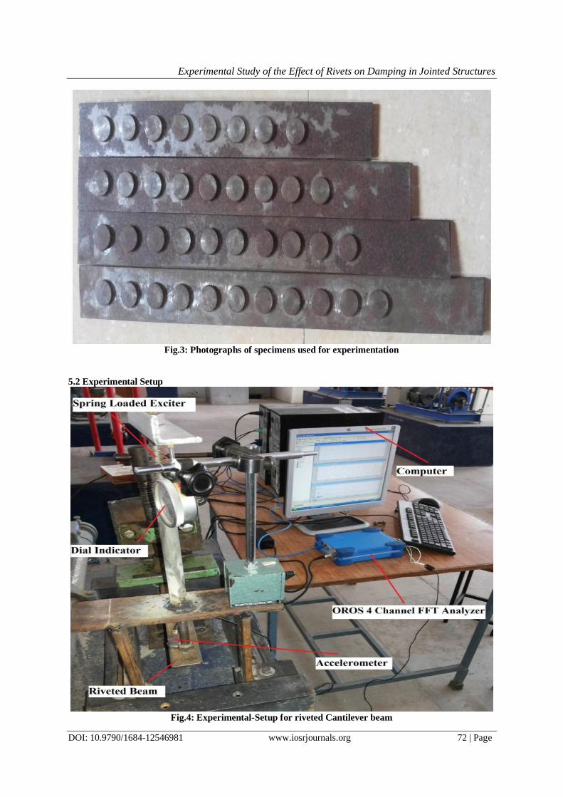
Fig.3: Photographs of specimens used for experimentation
5.2 Experimental Setup
Fig.4: Experimental-Setup for riveted Cantilever beam

Experimental Study of the Effect of Rivets on Damping in Jointed Structures
DOI: 10.9790/1684-12546981 www.iosrjournals.org 73 | Page
Fig.5: Side view of experimental set-up for cantilever beam
Experimental-Setup consists of following parts:-
1. OROS 4 Channel FFT Analyzer
2. Accelerometer
3. Spring Loaded Exciter
4. Riveted beam
5. Dial Indicator
The Experimental Set-up consists of frame work fabricated from steel C, I section by welding. The frame is
grounded to concrete base with foundation bolts. The one end of riveted beam is fixed using mechanical vice.
The spring loaded exciter is provided for giving excitation at the free end of riveted beam, this excitation is
noted on dial gauge.
5.3 Half Power Bandwidth Method
A spring loaded exciter is used to excite the specimens at the free ends. The excitation is imparted for a
range of beam-tip amplitudes varying from 1mm to 3mm. For a particular test specimen, the beam is deflected
and released to oscillate at its first mode of free vibration. The beam response is sensed by a contacting-type
accelerometer attached to the tip of the beam. One end of the accelerometer is held magnetically to the vibrating
surface of the specimen and the other is connected output of OROS 4 Channel FFT Analyzer. The output from
the accelerometer is proportional to the frequency and amplitude of vibration. These output signals are fed from
FFT Analyzer to digital computer using NVGate version 5.0 software for processing and display. The data is
then analysed to determine the natural frequency and damping characteristics of the beam structure. To estimate
damping ratio from frequency domain, half-power bandwidth method has been used.

Experimental Study of the Effect of Rivets on Damping in Jointed Structures
DOI: 10.9790/1684-12546981 www.iosrjournals.org 74 | Page
Fig.6: Half Power Bandwidth method of damping measurement
Damping Ratio(ξ) = F2-F1
2Fmax
VI. FINITE ELEMENT ANALYSIS FEA model of riveted beam is prepared using Ansys 11.0 software. The element type SHELL63 is used
for constructing the riveted beam. By applying the boundary condition to riveted cantilever beam, the problem is
solved using Harmonic analysis. The graph is plotted using Time History Post Processing tool.
TABLE 2: Steps of FEA model construction
Preferences Structural
Element Type SHELL63
(for Plate)
Material Properties EX= 1.96e5 N/mm2
PRXY= 0.3
Dimensions Width= 40mm
Thickness= 2mm,2.4mm,3mm,3.6mm,4mm
Length= 320mm,360mm,400mm,440mm
Number of Plates 2
Element Type BEAM188
(for Rivet)
Dimension of Rivets Diameter=10mm
Number of Rivets= 8,9,10,11

Experimental Study of the Effect of Rivets on Damping in Jointed Structures
DOI: 10.9790/1684-12546981 www.iosrjournals.org 75 | Page
Fig.7: FEA Model of Riveted beam with 8 number of rivets
Fig.8: FEA Model of Riveted beam with 9 number of rivets

Experimental Study of the Effect of Rivets on Damping in Jointed Structures
DOI: 10.9790/1684-12546981 www.iosrjournals.org 76 | Page
Fig.9: FEA Model of Riveted beam with 10 number of rivets
VII. RESULTS & DISCUSSION 7.1 Experimental Results
The following graph is obtained by performing experiments on various specimens of mild steel as
discussed in table 1. Time Domain graph, frequency domain graph are plotted for various specimen. Comparison is made with the solid beam and jointed beam of different thickness ratio. By using half power
bandwidth method the damping ratio (ξ) of specimen are evaluated. In present results, the variation of damping
ratio with respect to different influencing parameters such as beam thickness ratio, number of rivets is shown.
Fig.10: 3 axis (X, Y and Z) & vibration graph
Experimental Study of the Effect of Rivets on Damping in Jointed Structures
DOI: 10.9790/1684-12546981 www.iosrjournals.org 77 | Page
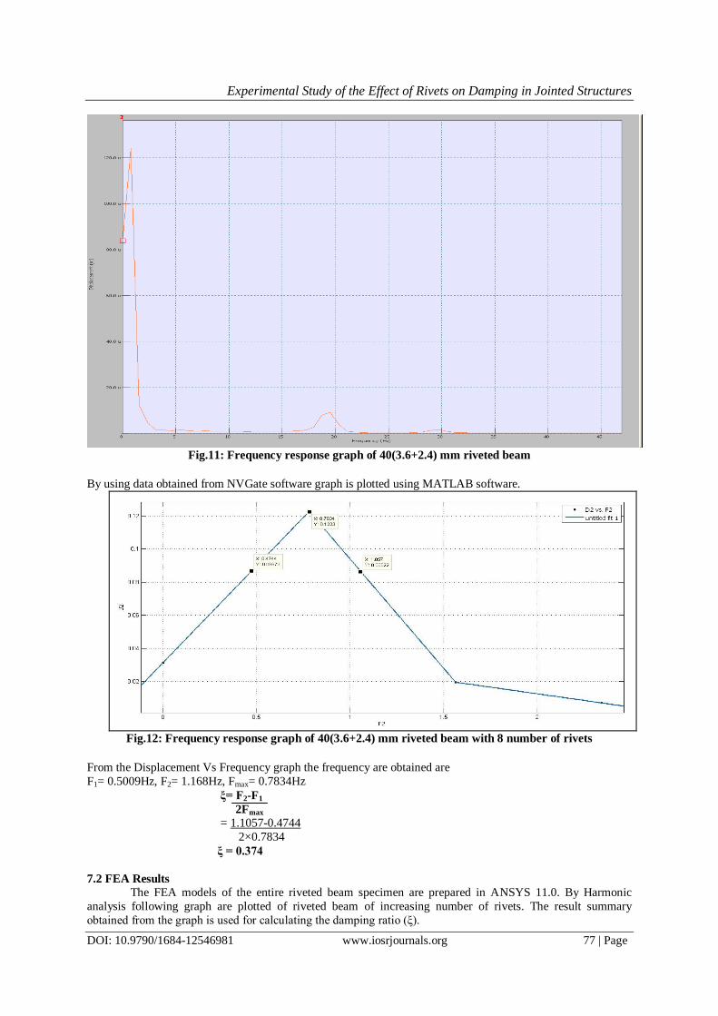
Fig.11: Frequency response graph of 40(3.6+2.4) mm riveted beam
By using data obtained from NVGate software graph is plotted using MATLAB software.
Fig.12: Frequency response graph of 40(3.6+2.4) mm riveted beam with 8 number of rivets
From the Displacement Vs Frequency graph the frequency are obtained are
F1= 0.5009Hz, F2= 1.168Hz, Fmax= 0.7834Hz
ξ= F2-F1
2Fmax
= 1.1057-0.4744
2×0.7834
ξ = 0.374
7.2 FEA Results
The FEA models of the entire riveted beam specimen are prepared in ANSYS 11.0. By Harmonic
analysis following graph are plotted of riveted beam of increasing number of rivets. The result summary
obtained from the graph is used for calculating the damping ratio (ξ).

Experimental Study of the Effect of Rivets on Damping in Jointed Structures
DOI: 10.9790/1684-12546981 www.iosrjournals.org 78 | Page
Fig.13: FEA Results of riveted cantilever beam
Fig.14: FEA Results of riveted cantilever beam
VIII. COMPARISON OF EXPERIMENTAL & FEA RESULTS OF RIVETED CANTILEVER BEAM The rivets beam of thickness 1.0, 1.5, 2.0 is analyzed for increasing number of rivets from 8 to 11. The
overall length of beam increases are pitch between two consecutive rivets is kept. These beam is excited for
1mm, 2mm, 3mm of excitation using spring loaded exciter.
The data obtained from FFT Analyzer are imported in MATLAB software for determining the damping ratio.
The data obtained from FEA Analysis are also imported in the software for calculating damping ratio.

Experimental Study of the Effect of Rivets on Damping in Jointed Structures
DOI: 10.9790/1684-12546981 www.iosrjournals.org 79 | Page
TABLE 3: Experimental and FEA Results of specimens
Sr.
No.
Width×Thickness
(mm×mm)
Number of
Rivets Damping ratio (ξ)
Experimental FEA
1mm 2mm 3mm 1mm 2mm 3mm
Thickness ratio =1.0
1.
40× (3+3)mm
8 0.472 0.423 0.3606 0.45 0.405 0.35
2. 9 0.4788 0.429 0.393 0.445 0.4 0.38
3. 10 0.4825 0.459 0.4 0.47 0.42 0.39
4. 11 0.4905 0.466 0.412 0.48 0.43 0.4
Thickness ratio =1.5
1.
40× (3.6+2.4)mm
8 0.374 0.349 0.335 0.37 0.33 0.31
2. 9 0.407 0.383 0.356 0.39 0.36 0.335
3. 10 0.434 0.405 0.388 0.42 0.38 0.36
4. 11 0.449 0.426 0.4 0.43 0.42 0.38
Thickness ratio =2.0
1.
40× (4+2)mm
8 0.3603 0.335 0.321 0.35 0.31 0.3
2. 9 0.372 0.364 0.338 0.365 0.34 0.315
3. 10 0.377 0.367 0.357 0.365 0.35 0.34
4. 11 0.388 0.3796 0.366 0.375 0.355 0.355
Fig.15: Experimental and FEA Results of damping ratio for Excitation 1mm with influencing parameter:-
Number of Rivets

Experimental Study of the Effect of Rivets on Damping in Jointed Structures
DOI: 10.9790/1684-12546981 www.iosrjournals.org 80 | Page
Fig.16: Experimental and FEA Results of damping ratio for Excitation 2mm with influencing parameter:
- Number of Rivets
0.26
0.29
0.32
0.35
0.38
0.41
0.44
8 9 10 11
Da
mp
ing
ra
tio
(ξ)
Number Of Rivets
Damping ratio(ξ) Vs Number of RivetsExperimental
Thickness Ratio
1.0
FEA Thickness
Ratio 1.0
Experimental
Thickness Ratio
1.5
FEA Thickness
Ratio 1.5
Experimental
Thickness Ratio
2.0
Fig.17: Experimental and FEA Results of damping ratio for Excitation 3mm with influencing parameter:
- Number of Rivets
IX. CONCLUSIONS The aim of this paper was to analyze the influence of joints and their functional parameters on the
vibration characteristics of built-up structures.
Effect of number of rivets: - The increase in dynamic slip is due using more number of rivets. Moreover, the
energy dissipation is enhanced as the contact area of the interface undergoing micro-slip increases with the
specimen length. The net effect of all these improves the damping with an increase in the cantilever length.
It is found from analysis that the thickness ratio of 1.0 yields maximum damping of jointed structures.
This damping will further increase with the use of more number of layers with the same overall beam thickness
due to more friction layers which produces higher energy loss at the interfaces.
Experimental Study of the Effect of Rivets on Damping in Jointed Structures
DOI: 10.9790/1684-12546981 www.iosrjournals.org 81 | Page
ACKNOWLEDGEMENT First and foremost, I would like to express my deep sense of gratitude and indebtedness to my guide
Dr. Y. R Kharde for his invaluable encouragement, suggestions and support from an early stage of this paper
and providing me extraordinary experiences throughout the work. Above all, his priceless and meticulous
supervision at each and every phase of work inspired me in innumerable ways. I am highly grateful to Dr. R. S
Jahagirdar, Principal, Pravara Rural Engineering College, Loni, Prof. R. R Kharde, Head, Department of
Mechanical Engineering and Prof. M. S Mhaske, PG Coordinator, Department of Mechanical Engineering for
their kind support and permission to use the facilities available in the Institute.
REFERENCES [1] B.K. Nanda, "Study of the effect of bolt diameter and washer on damping in layered and jointed structures" Journal of Sound and
Vibration 290 (2006), pp. 1290–1314.
[2] Masuko, M., Y. Ito, and K. Yoshida, "Theoretical analysis for a damping ratio of a jointed cantilever beam". Bulletin of JSME, 16(99) (1973), pp. 1421-1432.
[3] Nishiwaki., et al., "A Study on Damping Capacity of a Jointed Cantilever Beam": 1st Report; Experimental Results. Bulletin of
JSME 21(153) (1978), pp. 524-531.
[4] Den Hartog, J., Forced vibrations with combined Coulomb and viscous friction. Trans. ASME, 1931. 53(APM-53-9), pp. 107-115
[5] Olofsson, U. And L. Hagman," A model for micro-slip between flat surfaces based on deformation of ellipsoidal elastic bodies" Tribology international, (1997). 30(8): pp. 599-603.
[6] W. Chen, X. Deng "Structural damping caused by micro-slip along frictional interfaces" International Journal of Mechanical
Sciences 47 (2005) 1191–1211.
[7] Gould, H.H. and B. Mikic, “Areas of contact and pressure distribution in bolted joints" MIT Engineering Projects
Laboratory,[1970]. [8] Nanda, B. And A. Behera, “Study on damping in layered and jointed structures with uniform pressure distribution at the
interfaces.”Journal of Sound and Vibration,. 226(4) (1999), pp. 607-624.
[9] Damisa, O., et al., “Dynamic analysis of slip damping in clamped layered beams with non-uniform pressure distribution at the
interface" Journal of Sound and Vibration, 309(3-5) (2008), pp. 349-374. [10] Minakuchi, Y, Koizumi, and Shibuya, “Contact pressure measurement by means of ultrasonic waves using angle probes” Bulletin
of the JSME, 28(243) (1985), pp. 1859-1863.
[11] Beards, C. And J. Williams, "The damping of structural vibration by rotational slip in joints”. ”Journal of Sound and Vibration,
53(3) (1977), pp. 333-340.
[12] R.H Hodgar, Dr. Y R Kharde "Experimental Study of Effect of Damping in Steel Structures with Riveted joints” MECHPGCon-2015.
[13] Rahul H. Hodgar, Dr. Y.R Kharde, "Experimental And FEA Analysis Of Effect Of Damping In Steel Structures With Riveted
Joints" International Journal of Informative & Futuristic Research, Volume 3, Issue 1, September 2015
[14] S.P. Nigam and G.K Grover, Mechanical Vibrations, Nem Chand and sons.
[15] Dr. V.P. Singh, Mechanical Vibrations, Dhanpat Rai & Co (pvt). Ltd.