Embed Size (px)
Citation preview

JSCE Journal of Earthquake Engineering
1
SEISMIC TORSION RESPONSE
OF SKEWED BRIDGE PIERS
Paiboon TIRASIT1and Kazuhiko KAWASHIMA2
1 Graduate Student, Department of Civil Engineering, Tokyo Institute of Technology Tokyo 152-8552, Japan, [email protected]
2 Professor, Department of Civil Engineering, Tokyo Institute of Technology Tokyo 152-8552, Japan, [email protected]
Skewed bridge piers are suspected to be susceptible to seismic torsion during an earthquake because the inplane rotation of skewed bridge deck, due to the collision with the abutments or the adjacent spans, possibly causes the torsional rotations in the piers. An analytical study is carried out in order to investigate the seismic torsion response of skewed bridge piers. A 4 span continuous skewed bridge is analyzed by using the finite element method. Various conditions; skewed angle, pounding gap and the locking of steel bearing after failure, are taken into consideration. The analytical results indicate that the locking of bearing movement can cause sharp peak seismic torsion in skewed bridge pier.
Key words: Torsion, Skewed bridge, Reinforced concrete column, Seismic performance, Pounding, Steel bearing support, Bearing failure
1. INTRODUCTION During an earthquake, it is obvious that bridges are subjected to the multi-directional ground motions. The effect of bilateral excitation and vertical earthquake component can result in the combination of axial force, biaxial bending moment and shear force in bridge columns. However, special seismic design consideration is required for some specific bridges; such as bridges supported by c-bent columns, curved bridges and skewed bridges because of their irregular structural placement. In skewed bridges, the rotation of bridge deck about the vertical axis possibly takes place when it collides with the abutments or the adjacent spans during an earthquake1). This may possibly induce the torsional moment coupling with other internal force components in skewed bridge piers. Furthermore, the available experimental investigations indicate that the structural capacities of bridge piers significantly decrease when bridge piers are subjected to the combination of bending moment and torsion2), 3), 4), 5). Therefore, it is necessary to clarify the effect of seismic torsion in skewed bridge piers.
2. REPRESENTATIVE BRIDGES A 40-degree continuous span skewed bridge as illustrated in Figure 1 is selected to be the representative structure in this study. This bridge is 160-meter long and composed of 4 equal spans. The superstructure is composite type and supported by 3 concrete piers and 2 abutments. All piers are in T-shape with 10-meter height and both abutments are wall type with 5.1-meter height. 5 Steel bearings are employed at the top of each pier and abutment in order to support the superstructure. The types of steel bearings are also shown in Figure 1. “FB” and “MB” represent the fixed steel bearings and the movable steel bearings, respectively. The fixed steel bearings are employed at the tops of all piers and they do not allow the deck movement in longitudinal and transverse directions. In addition, the movable steel bearings are installed at the tops of both abutments and they permit the deck movement only in the longitudinal direction. Furthermore, cable restrainer systems are employed at both ends of this bridge. They are installed at 2 outermost and the center girders of the superstructure section.
A non-skew continuous span bridge with the

2
similar condition to the skewed bridge is also investigated in order to compare the effect of seismic torsion in its piers with that in the skewed bridge. 3. ANALYTICAL IDEALIZATION AND GROUND MOTION In this study, the finite element method is applied to analyze the behavior of skewed bridge. Both superstructure and substructure are modeled by using beam elements as presented in Figure 2. In order to include the nonlinear behavior in the plastic hinge region of bridge piers, Takeda deteriorating model as shown in Figure 3(a) is employed to the weak axis of pier section. Moreover, the pier cracking torsional stiffness is assumed to be 20% of that of full section.
Furthermore, the nonlinearity of pounding mechanism is taken into the consideration by using a spring element with the force-displacement relationship as shown in Figure 3(b). The direction of spring element is normal to the edge of skew and the pounding gap width is set to be 50 mm. The pounding springs connect the obtuse and acute
angles of bridge deck to the tops of abutments as shown in Figure 2. The stiffness of pounding spring,
Ik can be calculated as1), 6).
InEAkL
γ= (1)
where EA and L are the axial stiffness and the length of bridge deck, respectively; n is the total number of beam elements on the length L ; and γ is the stiffness ratio which is equal to 1.
The cable restrainer systems are idealized by spring elements with the force-displacement relationship shown in Figure 3(c). The restrainer gap width is set to be 50 mm along the longitudinal direction of bridge. The design force of cable restrainer, FH is evaluated as7)
1.5FH R= (2) in which R is the reaction due to superstructure dead load at abutment.
The nonlinearity of steel bearing is taken into the consideration. Figure 4(a) shows the configuration of the fixed steel bearing. The fixed steel bearing is modeled by a set of spring elements in the longitudinal and transverse directions including the nonlinear hysteretic model as shown in Figure 4(b).
10 10 10
102.
5
1.2
12
5.1
5.1
Figure 1. Representative bridge configuration (Unit: meter)
Figure 2. Finite element modeling of the skewed bridge

3
The fixed steel bearing is assumed to behave elastically before failure. The strength, yF , of a fixed steel bearing is evaluated as
yy h DL
allowF k R
σσ
= (3)
in which allowσ and yσ are the allowable stress and the yield strength for the steel design. The ratio of the yield strength and the allowable stress is set to be 1.7. hk is the seismic coefficient which is equal to 0.25 in this study and DLR is the reaction in bearing due to dead weight of superstructure.
Due to the lack of the information about the force displacement relationship of fixed steel bearing, the failure displacement is assumed to be 1 mm for whole fixed steel bearings. After this displacement, the fixed bearing is assumed to suffer damage and its lateral force capacity decreases and becomes
dependent on the friction force, dfF , between the upper and the lower parts of bearing. The friction force is assumed as
df DLF Rµ= (4) where µ is the friction coefficient which is assumed to be 0.15 in both transverse and longitudinal directions. When a fixed steel bearing suffers damage, the locking of bearing movement possibly occurs because smooth displacement between the upper and the lower parts of bearing does not take placement. In this study an additional spring element with the force-displacement relationship as shown in Figure 4(c) is provided. The locking of bearing movement is assumed to take place when the bearing displacement fills the movement gap in positive or negative direction. After that the steel bearing is supposed to have a very high stiffness, assuming to be equal to the pounding spring
Moment
Curvature
My
-My
- y y
(a) Moment-curvature hystereses (b) Model of pounding mechanism (c) Model of cable restrainer
Figure 3. Nonlinear models used in bridge analysis
Force
Displacement
Movement gap
ki
ki Movement gap
(a) Fixed steel bearing (b) Model of the behavior of fixed steel bearing (c) Model of bearing locking after
in longitudinal and transverse directions failure
Figure 4. Fixed steel bearing and its nonlinear model
Superstructure
Bridge pier
PTFE sheetTransverse direction
(a) Movable steel bearing (b) Model of the behavior of movable (c) Model of the behavior of movable steel bearing in transverse direction steel bearing in longitudinal direction
Figure 5. Movable steel bearing and its nonlinear model

4
stiffness, in order to restrain the bearing displacement.
Figure 5(a) shows the PTFE movable steel bearing used in this study. The behavior of movable steel bearing in the transverse direction is assumed to be the same as that of the fixed steel bearing (refer to Figure 5(b)). However, the bilinear hysteretic model as shown in Figure 5(c) is used to simulate the behavior of the movable steel bearing in the longitudinal direction since its capacity is directly dependent on the friction force. The initial movable bearing stiffness in the longitudinal direction is assumed to be equal to that in the transverse direction. The friction force of steel bearing can be calculated by Equation (4) and the friction coefficient is assumed to be equal to 0.10. The same value of friction coefficient is applied to the nonlinear model in the transverse direction of movable steel bearing. For the vertical direction, both fixed steel bearing and movable steel bearing are assumed to be rigid.
In the traditional way of seismic analysis of typical bridge structure, the torsional stiffness of bridge foundation is usually neglected. This results in the disappearance of the internal torsion in bridge piers. In fact, the torsional stiffness of bridge foundation exists. In this study, the foundation with reinforced concrete piles is employed and its torsional stiffness is contributed from the lateral stiffness of each pile as shown in Figure 6. The torsional stiffness of bridge foundation is calculated as
2
1
np
z li ii
K K rθ=
=∑ (5)
where ZKθ is the torsional stiffness of bridge foundation; pn is the total number of piles in the foundation; liK and ir are the lateral stiffness of i-th pile and the distance from the center of foundation to i-th pile, respectively.
In order to investigate the behavior of skewed bridges during an earthquake, NS and EW components of the JMA Kobe and JR Takatori ground motions which were measured during the 1995 Kobe earthquake are imposed to the bridge models in the longitudinal and transverse directions simultaneously. Because of space limitation, response under JMA Kobe as shown in Figure 7 is mainly presented here. The time history analysis is conducted by using the Newmark-β method. The constant acceleration is assumed in each step of numerical integration and the time interval of integration is 1x10⁻⁴ seconds. 4. NATURAL PERIODS AND MODE SHAPES OF SKEWED AND STRAIGHT BRIDGES The natural periods and the effective mass ratios of skewed bridge and straight bridge are shown in Tables 1 and 2. The fundamental modes of both bridges are in the transverse direction. The fundamental periods are 0.624 seconds and 0.571 seconds in the skewed bridge and the straight bridge, respectively. The natural mode shapes of skewed and straight bridges are presented in Figures 8 and 9, respectively.
ri K z
Kli
Pile no.i
Figure 6. Contribution of pile lateral stiffness to the torsional stiffness of foundation
-10-505
10
0 5 10 15 20Acc
erel
atio
n (m
/s2 )
Time(s)
PGA = 8.18 m/s2
-10-505
10
0 5 10 15 20Acc
erel
atio
n (m
/s2 )
Time(s)
PGA = 6.17 m/s2
(a) NS Component (b) EW component
Figure 7. JMA Kobe ground motion records for the time history analysis

5
5. EFFECT OF SKEWNESS, POUNDING AND RESTRAINER SYSTEM ON THE PERFORMANCE OF BRIDGES Figure 10 compares the seismic torsion occurring in each pier of skewed and straight bridges. It is assumed that no locking of steel bearing occurs in these analyses. It is found that the maximum seismic
torsions at all piers in skewed bridge are larger than those in straight bridge. In piers P1 and P3 of both skewed and straight bridges, seismic torsion occurs dependently on the inplane rotation of the deck as shown in Figure 11. Moreover, pier P2 in skewed bridge has two peaks of sharp torsion while the magnitude of torsion is much smaller at the same pier in straight bridge. This corresponds to the
Table 1 Natural periods of skewed bridge
Mode no. Direction Natural
periods (s) Effective
mass ratio (%)1 Transverse 0.624 47 4 Longitudinal 0.367 44 7 Vertical 0.233 31
(a) 1st mode: Transverse direction
(b) 4th mode: Longitudinal direction
(c) 7th mode: Vertical direction
Figure 8. Natural mode shapes of skewed bridge
-4-2024
Skewed bridgeStraight bridge
Tors
ion
(MN
m)
(a) Pier P1
-4-2024
Tors
ion
(MN
m)
(b) Pier P2
-4-2024
0 5 10 15 20
Tors
ion
(MN
m)
Time(s) (c) Pier P3
Figure 10. Seismic torsions of the piers in skewed and straight bridges
-0.005
0
0.005
Skewed bridgeStraight bridgeD
eck
Rot
atio
n (r
ad)
(a) Pier P1
-0.005
0
0.005
Dec
k R
otat
ion
(rad
)
(b) Pier P2
-0.005
0
0.005
0 5 10 15 20
Dec
k R
otat
ion
(rad
)
Time(s) (c) Pier P3
Figure 11. Inplane rotations of the deck in skewed and straight bridges
(a) 1st mode: Transverse direction
(b) 3rd mode: Longitudinal direction
(c) 8th mode: Vertical direction
Figure 9. Natural mode shapes of straight bridge
Table 2 Natural periods of straight bridge
Mode no. Direction Natural
periods (s) Effective
mass ratio (%)1 Transverse 0.571 51 3 Longitudinal 0.393 41 8 Vertical 0.233 34
3.77MNm
1.99MNm
2.53MNm
2.38MNm
1.99MNm
6
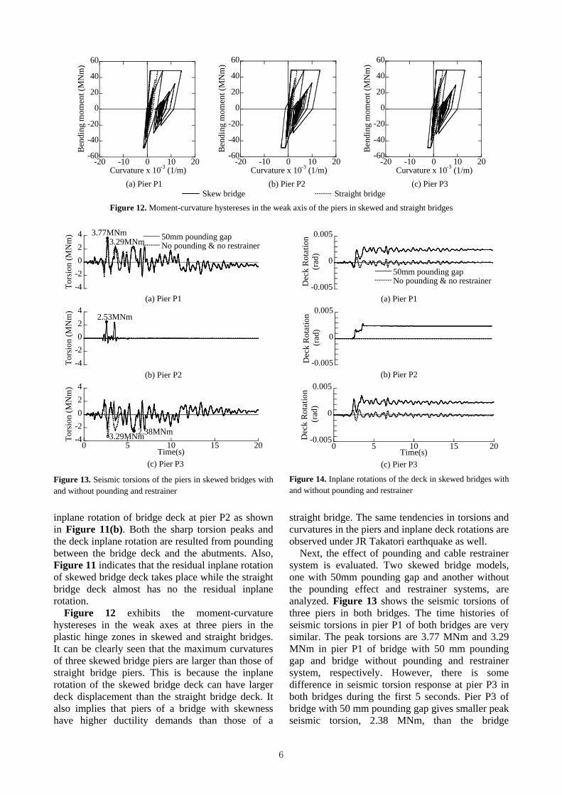
inplane rotation of bridge deck at pier P2 as shown in Figure 11(b). Both the sharp torsion peaks and the deck inplane rotation are resulted from pounding between the bridge deck and the abutments. Also, Figure 11 indicates that the residual inplane rotation of skewed bridge deck takes place while the straight bridge deck almost has no the residual inplane rotation. Figure 12 exhibits the moment-curvature hystereses in the weak axes at three piers in the plastic hinge zones in skewed and straight bridges. It can be clearly seen that the maximum curvatures of three skewed bridge piers are larger than those of straight bridge piers. This is because the inplane rotation of the skewed bridge deck can have larger deck displacement than the straight bridge deck. It also implies that piers of a bridge with skewness have higher ductility demands than those of a
straight bridge. The same tendencies in torsions and curvatures in the piers and inplane deck rotations are observed under JR Takatori earthquake as well. Next, the effect of pounding and cable restrainer system is evaluated. Two skewed bridge models, one with 50mm pounding gap and another without the pounding effect and restrainer systems, are analyzed. Figure 13 shows the seismic torsions of three piers in both bridges. The time histories of seismic torsions in pier P1 of both bridges are very similar. The peak torsions are 3.77 MNm and 3.29 MNm in pier P1 of bridge with 50 mm pounding gap and bridge without pounding and restrainer system, respectively. However, there is some difference in seismic torsion response at pier P3 in both bridges during the first 5 seconds. Pier P3 of bridge with 50 mm pounding gap gives smaller peak seismic torsion, 2.38 MNm, than the bridge
-60
-40
-20
0
20
40
60
-20 -10 0 10 20
Ben
ding
mom
ent (
MN
m)
Curvature x 10-3 (1/m)
-60
-40
-20
0
20
40
60
-20 -10 0 10 20
Ben
ding
mom
ent (
MN
m)
Curvature x 10-3 (1/m)
-60
-40
-20
0
20
40
60
-20 -10 0 10 20
Ben
ding
mom
ent (
MN
m)
Curvature x 10-3 (1/m) (a) Pier P1 (b) Pier P2 (c) Pier P3 Skew bridge Straight bridge
Figure 12. Moment-curvature hystereses in the weak axis of the piers in skewed and straight bridges
-4-2024 50mm pounding gap
No pounding & no restrainer
Tors
ion
(MN
m)
(a) Pier P1
-4-2024
Tors
ion
(MN
m)
(b) Pier P2
-4-2024
0 5 10 15 20
Tors
ion
(MN
m)
Time(s) (c) Pier P3
Figure 13. Seismic torsions of the piers in skewed bridges with and without pounding and restrainer
-0.005
0
0.005
50mm pounding gapNo pounding & no restrainerD
eck
Rot
atio
n(r
ad)
(a) Pier P1
-0.005
0
0.005D
eck
Rot
atio
n (r
ad)
(b) Pier P2
-0.005
0
0.005
0 5 10 15 20
Dec
k R
otat
ion
(rad
)
Time(s) (c) Pier P3
Figure 14. Inplane rotations of the deck in skewed bridges with and without pounding and restrainer
3.77MNm 3.29MNm
2.53MNm
3.29MNm 2.38MNm

7
response without pounding and restrainer, 3.29 MNm. Nevertheless, seismic torsion in Pier P2 in bridge without pounding effect and restrainer system is nearly zero along the time history and this is similar to that of straight bridge. This corresponds to the inplane rotations of bridge deck presented in Figure 14. It is obvious that the effect of pounding causes the inplane rotation of bridge deck. Figure 15 presents the moment-curvature hystereses in the pier weak axes in the plastic hinge regions of bridge with 50 mm pounding gap and bridge without pounding effect and restrainer system. It can be observed that the maximum curvatures at three piers in bridge with 50 mm pounding gap are slightly larger than those of bridge without pounding effect and restrainer. However, the opposite results were obtained under JR Takatori ground motion. It is said that the pounding is limited
on the maximum curvature of the column 6. EFFECT OF LOCKING OF BEARING AFTER FAILURE After the failure of steel bearings, the locking of bearing movement probably occurs due to the bearing damage. In order to evaluate the effect of locking of bearing, the rightmost fixed steel bearing on the top of pier P2 is assumed to lock in the longitudinal direction after damage (refer to Figures 1 and 2). Thus, the bearing locking spring element mentioned in section 3 is introduced to the longitudinal direction of that fixed steel bearing. The movement gap is assumed to be 10 mm in both positive and negative directions.
-60
-40
-20
0
20
40
60
-20 -10 0 10 20
Ben
ding
mom
ent (
MN
m)
Curvature x 10-3 (1/m)
-60
-40
-20
0
20
40
60
-20 -10 0 10 20
Ben
ding
mom
ent (
MN
m)
Curvature x 10-3 (1/m)
-60
-40
-20
0
20
40
60
-20 -10 0 10 20
Ben
ding
mom
ent (
MN
m)
Curvature x 10-3 (1/m) (a) Pier P1 (b) Pier P2 (c) Pier P3 50 mm pounding gap No pounding & no restrainer
Figure 15. Moment-curvature hystereses in the weak axis of the piers in skewed bridges with and without pounding and restrainer
-4-2024 With bearing locking
Without bearing locking
Tors
ion
(MN
m)
(a) Pier P1
-30
0
30
Tors
ion
(MN
m)
(b) Pier P2
-4-2024
0 5 10 15 20
Tors
ion
(MN
m)
Time(s) (c) Pier P3
Figure 16. Seismic torsions of the piers in skewed bridges with and without locking of bearing
-0.005
0
0.005
With bearing lockingWithout bearing lockingD
eck
Rot
atio
n (r
ad)
(a) Pier P1
-0.005
0
0.005D
eck
Rot
atio
n (r
ad)
(b) Pier P2
-0.005
0
0.005
0 5 10 15 20
Dec
k R
otat
ion
(rad
)
Time(s) (c) Pier P3
Figure 17. Inplane rotations of the deck in skewed bridges with and without locking of bearing
3.77MNm
16.9MNm
2.52MNm
3.72MNm
2.53MNm
2.38MNm

8
Figure 16 compares the seismic torsions in three piers of skewed bridges with and without bearing locking. It is seen that the time histories of seismic torsions and the peak torsion responses of piers P1 and P3 of both bridges are very close to each other. However, much higher torsion occurs at pier P2 in skewed bridge with bearing locking compared to that of without bearing locking. It is interesting to note that the deck inplane rotations of both bridges are very similar as shown in Figure 17. The reason is the locking occurs in the bearing support as shown in Figure 18 and the large eccentric impact
force causes the sharp peak torsion in pier P2. Figure 19 shows the force-displacement hystereses of the same fixed steel bearing when bearing locking does not take place. Under JR Takatori earthquake, torsion in pier P2 has the same trend as well.
Figure 20 shows the comparison of moment- curvature hystereses about the weak axes at three piers in the plastic hinge regions in bridges with and without bearing locking spring. The maximum curvatures in piers P1 and P3 of both bridges are very close to each other. The maximum curvature in
-800
-400
0
400
800
-0.02 -0.01 0 0.01 0.02
Bea
ring
forc
e (k
N)
Displacement (m)
-15
-10
-5
0
5
10
15
-0.02 -0.01 0 0.01 0.02
Bea
ring
lock
ing
forc
e (M
N)
Displacement (m)
-800
-400
0
400
800
-0.1 -0.05 0 0.05 0.1
Bea
ring
forc
e (k
N)
Displacement (m) (a) Longitudinal bearing spring (b) Bearing locking spring (Longitudinal direction) (c) Transverse bearing spring
Figure 18. Force-displacement hystereses of the rightmost fixed steel bearing on pier P2 in skewed bridge with locking of bearing
-800
-400
0
400
800
-0.1 -0.05 0 0.05 0.1
Bea
ring
forc
e (k
N)
Displacement (m)
-800
-400
0
400
800
-0.1 -0.05 0 0.05 0.1
Bea
ring
forc
e (k
N)
Displacement (m) (a) Longitudinal bearing spring (b) Transverse bearing spring
Figure 19. Force-displacement hystereses of the rightmost fixed steel bearing on pier P2 in skewed bridge without locking of bearing
-60
-40
-20
0
20
40
60
-20 -10 0 10 20
Ben
ding
mom
ent (
MN
m)
Curvature x 10-3 (1/m)
-60
-40
-20
0
20
40
60
-20 -10 0 10 20
Ben
ding
mom
ent (
MN
m)
Curvature x 10-3 (1/m)
-60
-40
-20
0
20
40
60
-20 -10 0 10 20
Ben
ding
mom
ent (
MN
m)
Curvature x 10-3 (1/m) (a) Pier P1 (b) Pier P2 (c) Pier P3 With bearing locking Without bearing locking
Figure 20. Moment-curvature hystereses in the weak axis of the piers in skewed bridges with and without locking of bearing

9
pier P2 with bearing locking and that of bridge without locking of bearing are virtually the same. This means that the effect of bearing locking is not significant on the column curvatures. The effect of pounding and restrainer system on the seismic torsions at the piers in bridges with locking of bearing is also investigated. Figure 21 exhibits the comparison of seismic torsions at the piers in skewed bridge with 50 mm pounding gap and skewed bridge without pounding effect and restrainer system. It can be noticed that the maximum seismic torsion at pier P1 in skewed bridge with 50 mm pounding gap, 3.72 MNm, is larger than that in skewed bridge without pounding effect and restrainer, 3.05 MNm. This phenomenon is reverse in pier P3. Nevertheless, the peak seismic torsion of 23.3 MNm at pier P2 in skewed bridge
without pounding effect and restrainer are larger than that in skewed bridge with 50 mm pounding gap, 16.9 MNm. This is opposite to the results in section 5 (refer to Figure 13). In Figure 22, the deck inplane rotation at pier P2 in skewed bridge without pounding effect and restrainer are much smaller than that in skewed bridge with 50 mm pounding gap. This indicates that the occurrence of peak seismic torsion in pier P2 in bridge without pounding effect and restrainer is resulted from the locking of bearing as shown in Figure 23. It is not dependent on the deck’s inplane rotation. Under JR Takatori ground excitation, pier P2 of skewed bridge without pounding gives larger torsion as well.
-4-2024 50mm pounding gap
No pounding & no restrainerTo
rsio
n (M
Nm
)
(a) Pier P1
-30
0
30
Tors
ion
(MN
m)
(b) Pier P2
-4-2024
0 5 10 15 20
Tors
ion
(MN
m)
Time(s) (c) Pier P3
Figure 21. Seismic torsions of the piers in skewed bridges with and without pounding and restrainer, considering the locking of bearing
-800
-400
0
400
800
-0.02 -0.01 0 0.01 0.02
Bea
ring
forc
e (k
N)
Displacement (m)
-15
-10
-5
0
5
10
15
-0.02 -0.01 0 0.01 0.02
Bea
ring
lock
ing
forc
e (M
N)
Displacement (m)
-800
-400
0
400
800
-0.1 -0.05 0 0.05 0.1
Bea
ring
forc
e (k
N)
Displacement (m) (a) Longitudinal bearing spring (b) Bearing locking spring (Longitudinal direction) (c) Transverse bearing spring
Figure 23. Force-displacement hystereses of the rightmost fixed steel bearing on pier P2 in skewed bridge without pounding and restrainer, considering the locking of bearing
-0.005
0
0.005
50mm pounding gapNo pounding & no restrainerD
eck
Rot
atio
n (r
ad)
(a) Pier P1
-0.005
0
0.005
Dec
k R
otat
ion
(rad
)
(b) Pier P2
-0.005
0
0.005
0 5 10 15 20
Dec
k R
otat
ion
(rad
)
Time(s) (c) Pier P3
Figure 22. Inplane rotations of the deck in skewed bridges with and without pounding and restrainer, considering the locking of bearing
3.05MNm
16.9MNm
2.52MNm
3.72MNm
23.3MNm
3.28MNm

10
7. CONCLUSIONS A finite element analysis is conducted in order to investigate the seismic torsional response of skewed bridge piers. Based on the results presented herein, the conclusions may be deduced as follows: 1) The seismic torsions in skewed bridge piers are larger than those of straight bridge piers. Moreover, skewed bridge piers have higher ductility demands. 2) The effect of pounding can be seen clearly in pier P2 which locates at the center of skewed bridge. The inplane deck rotation occurs due to the pounding between the skewed bridge deck and the abutments and it causes the seismic torsion in the piers. 3) The effect of pounding on the ductility demands of the piers in both skewed bridges with and without locking of bearing after failure is limited. 4) The seismic torsion in the middle pier of skewed bridge with locking of bearing after failure sharply increases compared to that without bearing locking. This torsion tends to decrease when pounding occurs between the deck and the abutments. However, the effect of bearing locking is less on the column curvature. REFERENCES 1) Kawashima, K. and Watanabe, G.: Effectiveness of
Cable-Restrainer for Mitigating Rotation of A Skewed Bridge Subjected to Strong Ground Shaking, Journal of Structural Mechanics and Earthquake Engineering, 675/I-55, 141-159. 2001. (In Japanese)
2) Hsu, H.-L. and Wang, C.-L.: Flexural-Torsional Behavior of Steel Reinforced Concrete Members Subjected to Repeated Loading, Earthquake Engineering and Structural Dynamics, 29, 667-682, 2000.
3) Hsu, H.-L. and Liang, L.-L.: Performance of Hollow Composite Members Subjected to Cyclic Eccentric Loading, Earthquake Engineering and Structural Dynamics, 32, 433-461, 2003.
4) Otsuka, H., Takeshita, E., Wan, Y., Yabuki, W., Tunumoto, M. and Yoshimura, T.: Study on the Seismic Performance of Reinforced Concrete Columns Subjected to Torsional Moment, Bending Moment and Axial Force, JSCE Journal of Earthquake Engineering, 27, 67 (CD-ROM), 8 pages, 2003. (In Japanese)
5) Tirasit, P., Kawashima, K. and Watanabe, G.: An Experimental Study on the Performance of RC Columns Subjected to Cyclic Flexural-Torsional Loading, Proceedings of 2nd International Conference on Urban Earthquake Engineering, Tokyo Institute of Technology, 357-364, 2005.
6) Kawashima, K. and Penzien, J.: Correlative Investigation on Theoretical and Experimental Dynamic Behavior of a Model Bridge Structure, Report No. UCB/EERC-76/26, Earthquake Engineering Research Center, University of California, Berkeley, U.S.A., 1976.
7) Japan Road Association: Specifications for Highway
Bridges - Part V Seismic Design, Maruzen, Tokyo, 1996.
(Received March 15, 2005)