Embed Size (px)
Citation preview

Seismic DesignManual
Volume ICode Application Examples

Copyright
Copyright © 1999 Structural Engineers Association of California. All rights reserved.This publication or any part thereof must not be reproduced in any form without thewritten permission of the Structural Engineers Association of California.
Publishe
Structural Engineers Association of California (SEAOC)
555 University Avenue, Suite 126Sacramento, California 95825-6510Telephone: (916) 427-3647; Fax: (916) 568-0677E-mail: [email protected]; Web address: www.seaint.org
The Structural Engineers Association of California (SEAOC) is a professionalassociation of four regional member organizations (Central California, NorthernCalifornia, San Diego, and Southern California). SEAOC represents the structuralengineering community in California. This document is published in keeping withSEAOC’s stated mission: “to advance the structural engineering profession; toprovide the public with structures of dependable performance through the applicationof state-of-the-art structural engineering principles; to assist the public in obtainingprofessional structural engineering services; to promote natural hazard mitigation; toprovide continuing education and encourage research; to provide structural engineerswith the most current information and tools to improve their practice; and to maintainthe honor and dignity of the profession.”
Editor
Gail Hynes Shea, Albany, California, [email protected]
Disclaime
Practice documents produced by the Structural Engineers Association of California(SEAOC) and/or its member organizations are published as part of our association’seducational program. While the information presented in this document is believed tobe correct, neither SEAOC nor its member organizations, committees, writers,editors, or individuals who have contributed to this publication make any warranty,expressed or implied, or assume any legal liability or responsibility for the use,application of, and/or reference to opinions, findings, conclusions, orrecommendations included in this publication. The material presented in thispublication should not be used for any specific application without competentexamination and verification of its accuracy, suitability, and applicability by qualifiedprofessionals. Users of information from this publication assume all liability arisingfrom such use.

Table of Contents
SEAOC Seismic Design Manual
Preface .......................................................................... ...................................v
Acknowledgments..................................................................... ..................................vi
Introduction .......................................................................... ...................................1Notation .......................................................................... ...................................3
Example 1 Earthquake Load Combinations:Strength Design ............................................... §1612.2......................7
Example 2 Combinations of Loads .................................... §1612.3....................12
Example 3 Seismic Zone 4 Near-Source Factor ................ §1629.4.2.................17Introduction to Vertical Irregularities ....................................... §1629.5.3.................20
Example 4 Vertical Irregularity Type 1 ............................. §1629.5.3.................21
Example 5 Vertical Irregularity Type 2 ............................. §1629.5.3.................24Example 6 Vertical Irregularity Type 3 ............................. §1629.5.3.................26
Example 7 Vertical Irregularity Type 4 ............................. §1629.5.3.................28
Example 8 Vertical Irregularity Type 5 ............................. §1629.5.3.................30Example 9 Vertical Irregularity Type 5 ............................. §1629.5.3.................32
Introduction to Plan Irregularities ............................................. §1629.5.3.................36
Example 10 Plan Irregularity Type 1 ................................... §1629.5.3.................37Example 11 Plan Irregularity Type 2 ................................... §1629.5.3.................41
Example 12 Plan Irregularity Type 3 ................................... §1629.5.3.................43
Example 13 Plan Irregularity Type 4 ................................... §1629.5.3.................45Example 14 Plan Irregularity Type 5 ................................... §1629.5.3.................46
Example 15 Reliability/Redundancy Factor ρ ..................... §1630.1.1.................47Example 16 Reliability/Redundancy Factor Applications... §1630.1.1.................52
Example 17 P∆ Effects......................................................... §1630.1.3.................56Example 18 Design Base Shear ........................................... §1630.2.1.................59
Example 19 Structure Period Using Method A.................... §1630.2.2.................61Example 20 Simplified Design Base Shear.......................... §1630.2.3.................65
Example 21 Combination of Structural Systems: Vertical... §1630.4.2.................68
Example 22 Combination of Structural Systems:Along Different Axes....................................... §1630.4.3.................71
Example 23 Combination of Structural Systems:Along the Same Axis ....................................... §1630.4.4.................73
Example 24 Vertical Distribution of Force .......................... §1630.5....................74Example 25 Horizontal Distribution of Shear...................... §1630.6....................76
Example 26 Horizontal Torsional Moments ........................ §1630.7....................81

Table of Contents
SEAOC Seismic Design Manual
Table of Contents (continued)
Example 27 Elements Supporting Discontinuous Systems.. §1630.8.2.................85Example 28 Elements Supporting Discontinuous Systems.. §1630.8.2.................88
Example 29 At Foundation................................................... §1630.8.3.................90
Example 30 Drift .................................................................. §1630.9....................96Example 31 Story Drift Limitations ..................................... §1630.10..................98
Example 32 Vertical Component ......................................... §1630.11................100
Example 33 Design Response Spectrum.............................. §1631.2..................101Example 34 Dual Systems.................................................... §1631.5.7...............104
Example 35 Lateral Forces for One-Story Wall Panels........ §1632.2..................107
Example 36 Lateral Forces for Two-Story Wall Panel ........ §1632.2..................111Example 37 Rigid Equipment............................................... §1632.2..................116
Example 38 Flexible Equipment .......................................... §1632.2..................118
Example 39 Relative Motion of Equipment Attachments.... §1632.4..................121Example 40 Deformation Compatibility .............................. §1633.2.4...............123
Example 41 Adjoining Rigid Elements................................ §1633.2.4.1............126
Example 42 Exterior Elements: Wall Panel ......................... §1633.2.4.2............128Example 43 Exterior Elements: Precast Panel...................... §1633.2.4.2............131
Example 44 Beam Horizontal Tie Force .............................. §1633.2.5...............138
Example 45 Collector Elements ........................................... §1633.2.6...............139
Example 46 Out-of-Plane Wall Anchorage toFlexible Diaphragm.......................................... §1633.2.8.1............142
Example 47 Wall Anchorage to Flexible Diaphragms......... §1633.2.8.1............145
Example 48 Determination of Diaphragm Force Fpx:Lowrise............................................................. §1633.2.9...............147
Example 49 Determination of Diaphragm Force Fpx:Highrise............................................................ §1633.2.9...............150
Example 50 Building Separations ........................................ §1633.2.11.............152
Example 51 Flexible Nonbuilding Structure........................ §1634.2..................154Example 52 Lateral Force on Nonbuilding Structure........... §1634.2..................157
Example 53 Rigid Nonbuilding Structure ............................ §1634.3..................159
Example 54 Tank With Supported Bottom .......................... §1634.4..................160Example 55 Pile Interconnections........................................ §1807.2..................161

Preface
SEAOC Seismic Design Manual
This document is the initial volume in the three-volume SEAOC Seismic DesignManual. It has been developed by the Structural Engineers Association of Californi(SEAOC) with funding provided by SEAOC. Its purpose is to provide guidance onthe interpretation and use of the seismic requirements in the 1997 Uniform BuildingCode (UBC), published by the International Conference of Building Official(ICBO), and SEAOC’s 1999 Recommended Lateral Force Requirements andCommentary (also called the Blue Book).
The Seismic Design Manual was developed to fill a void that exists between theCommentary of the Blue Book, which explains the basis for the UBC seismicprovisions, and everyday structural engineering design practice. The Seismic DesignManual illustrates how the provisions of the code are used. Volume I: CodeApplication Examples, provides step-by-step examples of how to use individual codeprovisions, such as how to compute base shear or building period. Volumes II and III:Building Design Examples, furnish examples of the seismic design of common typesof buildings. In Volumes II and III, important aspects of whole buildings are designedto show, calculation-by-calculation, how the various seismic requirements of the codeare implemented in a realistic design.
SEAOC intends to update the Seismic Design Manual with each edition of thebuilding code used in California.
Ronald P. GallagherProject Manager

Acknowledgements
SEAOC Seismic Design Manual
Authors
The Seismic Design Manual was written by a group of highly qualified structuralengineers. These individuals are both California registered structural engineers andSEAOC members. They were selected by a Steering Committee set up by theSEAOC Board of Directors and were chosen for their knowledge and experience withstructural engineering practice and seismic design. The Consultants for Volumes I, IIand III are
Ronald P. Gallagher, Project ManagerDavid A. HutchinsonJon P. KilandJohn W. LawsonJoseph R. MaffeiDouglas S. ThompsonTheodore C. Zsutty
Volume I was written principally by Theodore C. Zsutty and Ronald P. Gallagher.Many useful ideas and helpful suggestions were offered by the other Consultants.Consultant work on Volumes II and III is currently underway.
Steering Committee
Overseeing the development of the Seismic Design Manual and the work of theConsultants was the Project Steering Committee. The Steering Committee was madeup of senior members of SEAOC who are both practicing structural engineers andhave been active in Association leadership. Members of the Steering Committeeattended meetings and took an active role in shaping and reviewing the document.The Steering Committee consisted of
John G. Shipp, ChairRobert N. ChittendenStephen K. HarrisMaryann T. PhippsScott A. Stedman

Acknowledgments
SEAOC Seismic Design Manual
Reviewers
A number of SEAOC members and other structural engineers helped check theexamples in this volume. During its development, drafts of the examples were sent tothese individuals. Their help was sought in both review of code interpretations aswell as detailed checking of the numerical computations. The assistance of thefollowing individuals is gratefully acknowledged
Saeed R. AmiraziziJefferson W. AsherBrent BerensenDonald A. CushingVincent DeVitaRichard M. DrakeTodd W. EricksonDaniel FisherKenneth GebharEdward R. Haninger
Thomas HuntMark S. JokerstIsao M. KawasakiJohn W. LawsonRonald LugueRobert LyonsPeter MaranianBrian McDonalRory M. McGruerBrian Montes
Manuel MordenFarzad NaeimDavid A. NapoleonJosh PlummerMehran PourzanjaniIan RobertsonJohn G. ShippDonald R. Strand
Seismology Committee
Close collaboration with the SEAOC Seismology Committee was maintained duringthe development of the document. The 1997-1998 and 1998-1999 Committeesreviewed the document and provided many helpful comments and suggestions. Theirassistance is gratefully acknowledged.
1998-1999Saif M. Hussain, ChairTom H. Hale, Past ChairRobert N. ChittendenStephen K. HarrisDouglas HohbachY. Henry HuangSaiful IslamMartin W. JohnsonJaiteerth B. KinhaEric T. LehmkuhlSimin NaasehHassan Sassi, Assistant to the Chair
1997-1998Tom H. Hale, ChairAli M. Sadre, Past ChairRobert N. ChittendenStephen K. HarrisSaif M. HussainSaiful IslamMartin W. JohnsonEric T. LehmkuhlRoumen V. MladjovSimin NaasehCarl B. SchulzeChris V. TokasJoyce Copelan, Assistant to the Chair
Production and Art
Special thanks are due Lenore Henry of R.P. Gallagher Associates, Inc. who input theentire text from handwritten copy, did all the subsequent word processing, drew althe figures, and formatted the entire document. Without her expertise, this projectwould never have come to fruition.

Suggestions for Improvement
SEAOC Seismic Design Manual
Suggestions for Improvement
In keeping with two of its Mission Statements: (1) “to advance the structuraengineering profession” and (2) “to provide structural engineers with the most currentinformation and tools to improve their practice”, SEAOC plans to update thisdocument as seismic requirements change and new research and better understandingof building performance in earthquakes becomes available.
Comments and suggestions for improvements are welcome and should be sent to thefollowing:
Structural Engineers Association of California (SEAOC)Attention: Executive Director555 University Avenue, Suite 126Sacramento, California 95825-6510Telephone: (916) 427-3647; Fax: (916) 568-0677E-mail: [email protected]; Web address: www.seaint.org
Errata Notification
SEAOC has made a substantial effort to ensure that the information in this documentis accurate. In the event that corrections or clarifications are needed, these will beposted on the SEAOC web site at http://www.seaint.org or on the ICBO website athttp://ww.icbo.org. SEAOC, at its sole discretion, may or may not issue writtenerrata.

Seismic DesignManual
Volume ICode Application Examples

Introduction
SEAOC Seismic Design Manual
Volume I of the SEAOC Seismic Design Manual: Code Application Examples dealswith interpretation and use of the seismic provisions of the 1997 Uniform BuildingCode (UBC). The Seismic Design Manual is intended to help the reader understandand correctly use the UBC seismic provisions and to provide clear, concise, andgraphic guidance on the application of specific provisions of the code. It primariladdresses the major seismic provisions of Chapter 16 of the UBC, with interpretationof specific provisions and examples highlighting their proper application.
Volume I presents 55 examples that illustrate the application of specific seismicprovisions of the UBC. Each example is a separate problem, or group of problems,and deals primarily with a single code provision. Each example begins with adescription of the problem to be solved and a statement of given information. Theproblem is solved through the normal sequence of steps, each of which are illustratedin full. Appropriate code references for each step are identified in the right-handmargin of the page.
The complete Seismic Design Manual will have three volumes. Volumes II and IIIwill provide a series of seismic design examples for buildings illustrating the seismicdesign of key parts of common building types such as a large three-story wood framebuilding, a tilt-up warehouse, a braced steel frame building, and a concrete shear walbuilding.
While the Seismic Design Manual is based on the 1997 UBC, there are someprovision of SEAOC’s 1999 Recommended Lateral Force Provisions andCommentary (Blue Book) that are applicable. When differences between the UBCand Blue Book are significant, these are brought to the attention of the reader.
The Seismic Design Manual is applicable in regions of moderate and high seismicity(e.g., Zones 3 and 4), including California, Nevada, Oregon, and Washington. It isintended for use by practicing structural engineers and structural designers, buildingdepartments, other plan review agencies, and structural engineering students.

How to Use This Document
SEAOC Seismic Design Manual
The various code application examples of Volume I are organized in numerical orderby 1997 UBC section number. To find an example for a particular provision of thecode, look at the upper, outer corner of each page, or in the table of contents.
Generally, the UBC notation is used throughout. Some other notation is also definedin the following pages, or in the examples.
Reference to UBC sections and formulas is abbreviated. For example, “1997 UBCSection 1630.2.2” is given as §1630.2.2 with 1997 UBC being understood. “Formula(32-2)” is designated Equation (32-2) or just (32-2) in the right-hand margins.Throughout the document, reference to specific code provisions and equations (theUBC calls the latter formulas) is given in the right-hand margin under the categoryCode Reference. Similarly, the phrase “Table 16-O” is understood to be 1997 UBCTable 16-O.
Generally, the examples are presented in the following format. First, there is astatement of the example to be solved, including given information, diagrams, andsketches. This is followed by the “Calculations and Discussion” section, whichprovides the solution to the example and appropriate discussion to assist the reader.Finally, many of the examples have a third section designated “Commentary.” In thislatter section, comments and discussion on the example and related material aremade. Commentary is intended to provide a better understanding of the exampleand/or to offer guidance to the reader on use of the information generated in theexample.
In general, the Volume I examples focus entirely on use of specific provisions of thecode. No design is illustrated. Design examples are given in Volumes II and III.
The Seismic Design Manual is based on the 1997 UBC, unless otherwise indicated.Occasionally, reference is made to other codes and standards (e.g., ACI 318-95 or1997 NDS). When this is done, these documents are clearly identified.

Notation
SEAOC Seismic Design Manual
The following notations are used in this document. These are generally consistentwith that used in the UBC. However, some additional notations have also been added.
AB = ground floor area of structure in square feet to include areacovered by all overhangs and projections.
Ac = the combined effective area, in square feet, of the shear wallsin the first story of the structure.
Ae = the minimum cross-sectional area in any horizontal plane inthe first story, in square feet of a shear wall.
Ax = the torsional amplification factor at Levex.
ap = numerical coefficient specified in §1632 and set forth in Table16-O of UBC.
Ca = seismic coefficient, as set forth in Table 16-Q of UBC.
Ct = numerical coefficient given in §1630.2.2 of U BC.
Cv = seismic coefficient, as set forth in Table 16-R of UBC.
D = dead load on a structural element.
De = the length, in feet, of a shear wall in the first story in thedirection parallel to the applied forces.
E, Eh, Em, Ev, Fi, Fn = earthquake loads set forth in §1630.1 of UBC.
Fx = design seismic force applied to Levei, n or x, respectively.
Fp = design seismic force on a part of the structure.
Fpx = design seismic force on a diaphragm.
Ft = that portion of the base shear, V, considered concentrated atthe top of the structure in addition to Fn.
Fa = axial stress.

Notation
SEAOC Seismic Design Manual
Fy = specified yield strength of structural steel.
fc’ = specified compressive strength of concrete.
fi = lateral force at Level i for use in Formula (30-10) of UBC.
fm’ = specified compressive strength of masonry.
fp = equivalent uniform load.
fy = specified yield strength of reinforcing steel
g = acceleration due to gravity.
hi, hn,hx= height in feet above the base to Levei, n or x, respectively.
I = importance factor given in Table 16-K of UBC.
Ip = importance factor specified in Table 16-K of UBC.
L = live load on a structural element.
Level i = level of the structure referred to by the subscript i. “i = 1”designates the first level above the base.
Level n= that level that is uppermost in the main portion of thestructure.
Level x= that level that is under design consideration. “x = 1”designates the first level above the base.
Na = near-source factor used in the determination of Ca in SeismicZone 4 related to both the proximity of the building orstructure to known faults with magnitudes and slip rates as setforth in Tables 16-S and 16-U of UBC.
Nv = near-source factor used in the determination of Cv in SeismicZone 4 related to both the proximity of the building orstructure to known faults with magnitudes and slip rates as setforth in Tables 16-T and 16-U of UBC.
R = numerical coefficient representative of the inherentoverstrength and global ductility capacity of lateral-force-resisting systems, as set forth in Table 16-N or 16-P of UBC.

Notation
SEAOC Seismic Design Manual
r = a ratio used in determining ρ. See §1630.1 of UBC.
SA, SB, SC, SD, SE, SF = soil profile types as set forth in Table 16-J of UBC.
T = elastic fundamental period of vibration, in seconds, of thestructure in the direction under consideration.
V = the total design lateral force or shear at the base given byFormula (30-5), (30-6), (30-7) or (30-11) of UBC.
Vx = the design story shear in Story x.
W = the total seismic dead load defined in §1620.1.1 of UBC.
wi, wx = that portion of W located at or assigned to Level i or x,respectively.
Wp = the weight of an element of component.
wpx = the weight of the diaphragm and the element tributary theretoat Level x, including applicable portions of other loadsdefined in §1630.1.1 of UBC.
Z = seismic zone factor as given in Table 16-I of UBC.
∆M = Maximum inelastic response displacement, which is the totadrift or total story drift that occurs when the structure issubjected to the Design Basis Ground Motion, includingestimated elastic and inelastic contributions to the totaldeformation defined in §1630.9 of UBC.
∆S = Design level response displacement, which is the total drift ortotal story drift that occurs when the structure is subjected tothe design seismic forces.
δi = horizontal displacement at Level i relative to the base due toapplied lateral forces, f, for use in Formula (30-10) of UBC.
φ = capacity-reduction or strength-reduction factor.
ρ = Redundancy/reliability factor given by Formula (30-3) of UBC.
Ωo = Seismic force amplification factor, which is required toaccount for structural overstrength and set forth in Table 16-Nof UBC.

Example 1 Earthquake Load Combinations: Strength Design §1612.2
SEAOC Seismic Design Manual
! "# # $%&'&
This example demonstrates the application of the strength design load combinationsthat involve the seismic load E given in §1630.1.1. This will be done for the moment-resisting frame structure shown below:
Zone 444.0=aC
0.1=I1.1=ρ5.01 =f
Snow load 0=S
Beam A-B and Column C-D are elements of the special moment-resisting frame.Structural analysis has provided the following individual beam moments at A, and thecolumn axial loads and moments at C due to dead load, office building live load, andlateral seismic forces.
Dead Load D Live Load L Lateral Seismic Load Eh
Beam Moment at A 100 kip-ft 50 kip-ft 120 kip-ft
Column C-D Axial Load 90 kips 40 kips 110 kips
Column Moment at C 40 kip-ft 20 kip-ft 160 kip-ft
Find the following:
Strength design moment at beam end A.
Strength design axial load and moment at column top C.
C
D
BA

§1612.2 Example 1 Earthquake Load Combinations: Strength Design
SEAOC Seismic Design Manual
Calculations and Discussion Code Reference
Strength design moment at beam end A.
To determine strength design moments for design, the earthquake component E mustbe combined with the dead and live load components D and L . This process isillustrated below.
Determine earthquake load E: §1630.1.1The earthquake load E consists of two components as shown below inEquation (30-1). hE is due to horizontal forces, and vE is due to vertical
forces.
vh EEE +ρ= (30-1)
The moment due to vertical earthquake forces is calculated as
( )( )( ) ft-k22100 0.1 44.0 5.05.0 === IDCE av §1630.1.1
The moment due to horizontal earthquake forces is given as
ft-k120=hE
Therefore
( ) ft-k154221201.1 =+=+ρ= vh EEE
Apply earthquake load combinations: §1612.2.1The basic load combinations for strength design (or LRFD) are given in§1612.2.1. For this example, the applicable equations are:
LfED 10.12.1 ++ (12-5)
ED 0.19.0 ± (12-6)
Using Equation (12-5) and Equation (12-6), the strength design moment at Afor combined dead, live, and seismic forces are determined.
( ) ( ) ( ) ft-k299505.01540.11002.10.12.1 1 =++=++= LEDA MfMMM
( ) ( ) ft-k64 ft -k2441540.11009.00.19.0 −=±=±= orMMM EDA
ft-k64 ft-k299 −=∴ orM A

Example 1 Earthquake Load Combinations: Strength Design §1612.2
SEAOC Seismic Design Manual
Specific material requirements:There are different requirements for concrete (and masonry) frames than forsteel as follows.
Structural Steel: Section 2210 specifies use of the load combinations of§1612.2.1 as given above without modification.
Reinforced Concrete: Section 1909.2.3 specifies use of the loadcombinations of §1612.2.1, where Exception 2 requires the factor loadcombinations of Equation (12-5) and Equation (12-6) to be multiplied by 1.1for concrete and masonry elements. (Note: At the time of publication, April1999, the 1.1 factor is under consideration for change to 1.0.) Therefore, for areinforced concrete frame, the combinations are:
( ) LfEDLfED 11 1.11.132.10.12.11.1 ++=++ (12-5)
( ) EDED 1.199.00.19.01.1 ±=± (12-6)
( ) ft-k9.328ft-k2991.1 ==AM
( ) ft-k4.70 ft -k4.268ft-k64 ft -k2441.1 −=−= ororM A
ft-k4.70 ft-k9.328 −=∴ orM A for a concrete frame.
Strength design axial load and moment at column top C.
Determine earthquake load E: §1630.1.1
vh EEE +ρ= (30-1)
where
DIDCE av 22.05.0 == §1630.1.1
For axial load
( ) ( ) kips 8.140kips 90 22.0kips 110 1.1 =+=+= vh EEE
For moment
( ) ( ) ft-k8.184ft-k4022.0ft-k1601.1 =+=+= vh EEE

§1612.2 Example 1 Earthquake Load Combinations: Strength Design
SEAOC Seismic Design Manual
Apply earthquake load combinations: §1630.1.1
LfED 10.12.1 ++ (12-5)
ED 0.19.0 ± (12-6)
Design axial force CP at point C is calculated as
( ) ( ) ( ) kips 8.26840 5.08.140 0.190 2.10.12.1 1 =++=++= LfEDPC
( ) ( ) kips 8.598.2218.140 0.190 9.00.19.0 −=±=±= andEDPC
kips 8.268=∴ CP compression, or kips 8.59 tension
Design moment CM at point C is calculated as
( ) ( ) ( ) ft-k8.242ft-k20 5.0ft-k8.184 0.1ft-k40 2.10.12.1 1 =++=++= LfEDMC
( ) ( ) ft-k8.148 ft -k8.220ft-k8.1840.1ft-k40 9.00.1 9.0 −=±=±= orEDM C
∴ =CM 242.8 k-ft or –148.8 k-ft
Note that the column section capacity must be designed for the interaction ofkips8.268=CP compression and 8.242=CM k-ft (for dead, live and
earthquake), and the interaction of kips 8.59=CP tension and
8.148−=CM k-ft (for dead and earthquake).
Specific material requirements §1630.1.1Structural Steel: Section 2210 specifies the use of the load combinations of§1612.2.1 as given above without modification.
Reinforced Concrete: The axial force CP and the moment CM must be
multiplied by 1.1 per §1612.2.1.
Commentary
Use of strength design requires consideration of vertical seismic load vE . When
allowable stress design is used, the vertical seismic load vE is not required under
§1630.1.1.

Example 1 Earthquake Load Combinations: Strength Design §1612.2
SEAOC Seismic Design Manual
The incorporation of vE in the load combinations for strength design has the effect
of increasing the load factor on the dead load action D. For example, consider theload combination of Equation (12-5)
( )SfLfED 210.12.1 +++ (12-5)
where vh EEE +ρ=
and IDCE av 5.0=
this becomes
( ) ( )SfLfEIDCD ha 215.0 0.12.1 ++ρ++
( ) ( )SfLfEDIC ha 210.1 5.02.1 ++ρ++
in the numerical example
22.05.0 =ICa
Thus, the total factor on D is 42.122.02.1 =+
For the allowable stress design load combinations of §1612.3, vE may be taken as
zero. When these combinations are converted to an equivalent strength design basis,the resulting factor on dead load D is comparable to ( )ICa5.02.1 + in §1612.2.
For example, consider the following:
The basic load combinations of §1612.3.1, without increase in allowable stresses,have a 1.70 factor on D (using the procedure permitted in §1630.8.2.1 for conversionto design strength).
The alternate basic load combinations of §1612.3.2 with a permitted one-third
increase in allowable stress has a 28.133.1
70.1 = factor on D.

§1612.3 Example 2 Combinations of Loads
SEAOC Seismic Design Manual
&
$%&'(
The code requires the use of allowable stress design for the design of wood membersand their fastenings (see §2301 and §2305). Section 1612.3 permits two differentcombinations of load methods. These are:
1. Allowable stress design (ASD) of §1612.3.1
2. Alternate allowable stress design of §1612.3.2
This example illustrates the application of each of these methods. This is done for theplywood shear wall shown below. The wall is a bearing wall in a light wood framedbuilding.
The following information is given:
Zone 401.I =01.=ρ400.Ca =
kips0.4=EV (seismic forcedetermined from §1630.2)
Gravity loads:Dead klf3.0=Dw (tributary
dead load, including weightof wall)
Live 0=Lw (roof load supported by
other elements)
Determine the required design loads for shear capacity q and hold-down capacity Tfor the following load combinations:
Basic allowable stress design.
Alternate allowable stress design.
Pt. O
Plywoodshear wall
h = 9'
Nailing
Hold-down
VE
q
L = 10'
9' - 7"
Gravity loads

Example 2 Combinations of Loads §1612.3
SEAOC Seismic Design Manual
Calculations and Discussion Code Reference
Basic allowable stress design. §1612.3.1
The governing load combinations for basic allowable stress design are Equations (12-9), (12-10) and (12-11). These are used without the usua one-third stress increaseexcept as permitted by 1809.2 for soil pressure. For wood design, however, theallowable stresses for short-time loads due to wind or earthquake may be used.
4.1
ED + (12-9)
4.19.0
ED ± (12-10)
4.175.075.0
ELD ++ (12-11)
where
hhvh EOEEEE =+=+ρ= )0.1( (30-1)
Note that under the provisions of §1630.1.1, vE is taken as zero for ASD.
Dead and live load are not involved when checking shear, and both the governingEquations (12-10) and (12-11) reduce to E.01 . In this example, E reduces to hE .
For checking tension (hold-down capacity), Equation (12-10) governs. Whenevercompression is checked, then Equations (12-9) and (12-11) must be checked.
Required unit shear capacity q.Base shear and the resulting element seismic forces determined under§1630.2 are on a strength design basis. For allowable stress design, thesemust be divided by 1.4 as indicated above in Equations (12-9), (12-10) and(12-11). Thus
lbs857,24.1
000,4
4.14.14.1===== ASD
eh VVEE
The unit shear is
plf28601
857,2 =′
==L
Vq ASD
This unit shear is used to determine the plywood thickness and nailingrequirements from Table 23-ΙΙ-I-1. Footnote 1 of that Table states that theallowable shear values are for short-time loads due to wind or earthquake.

§1612.3 Example 2 Combinations of Loads
SEAOC Seismic Design Manual
Required hold-down capacity T.Taking moments about point O at the right edge of wall and using
lbs875,2=EV , the value of the hold-down force ET due to horizontal
seismic forces is computed
EE VT 958.9 =
kips68.285.9
857.29
58.9
9 =′
×′== V
TE
Using Equation (12-10) the effect of dead load and seismic forces arecombined to determine the required ASD hold-down capacity. In thisexample
( )( ) ( )( ) kips5.1103.02
101
2
1 ==′= DwD
( ) kips33.168.25.19.09.04.1
9.0 −=−=−=−= ETDE
DT tension (12-10)
This value is used for the selection of the premanufactured hold-down elements.Manufacturer’s catalogs commonly list hold-down sizes with their “×331. allowable”capacity values. Here the 331. value represents the allowed Load Duration factor,
DC , given in Table 2.3.2 of §2316.2 for resisting seismic loads. This is not
considered a stress increase (although it has the same effect). Therefore, the“ ×331. allowable” capacity values may be used to select the appropriate hold-downelement.
Alternate allowable stress design. §1612.3.2
Under this method of load combination, the customary one-third increase inallowable stresses is allowed. However, Item 5 of §2316.2 states that the one-thirdincrease shall not be used concurrently with the load duration factor DC . The
governing load combinations, in the absence of snow load, are the following:
4.1
ELD ++ (12-13)
4.19.0
ED ± (12-16-1)
where ( ) hhvh EOEEEE =+=+ρ= 0.1 (30-1)
Note: Equation (12-16-1) is a May 1998 errata for the first printing of the code.

Example 2 Combinations of Loads §1612.3
SEAOC Seismic Design Manual
Note that vE is taken as zero for ASD per §1630.1.1.
Required unit shear capacity q.
lbs857,24.1
000,4
4.14.14.1===== ASD
eh VVEE
plf28610
856,2 ===L
Vq ASD
This value may be used directly to select the plywood thickness and nailingrequirements from Table 23-ΙΙ-I-1. This method recognizes that Table 23-ΙΙ-I-1 already includes a 1.33 allowable stress increase for seismic loading, andthe one-third increase cannot be used again with the tabulated values.
Required hold-down capacity T.Taking moments about point O at the right edge of wall for only seismicforces
EE VT 958.9 =
( )kips68.2
58.9
kips857.29==ET
The dead load effect on the hold-down is one-half the dead load. Thus,
( )( ) ( )( ) kips5.1103.02
101
2
1 ==′= DwD
The governing tension is determined from Equation (12-16-1)
( ) kips33.168.25.19.09.04.1
9.0 −=−=−=−= ETDE
DT tension (12-10)
This value may be used directly, without modification, to select the“ ×331. allowable” capacity of the hold-down elements. Note that the“ ×331. allowable” value can be considered either as the one-third increasepermitted by §1612.3.1, or the use of a load-duration factor of 33.1=DC .

§1612.3 Example 2 Combinations of Loads
SEAOC Seismic Design Manual
Commentary
For wood design, the use of the load duration factor DC is not considered as an
increase in allowable stress. Together with the other factors employed in establishingthe allowable resistance of wood elements, it is the means of representing the extrastrength of wood when subject to short duration loads and provides the allowablestress for wind or earthquake load conditions. The allowable shear values given in theChapter 23 Tables 23-II-H, 23-II-I-1, and 23-II-1-2 are based on this use of this loadduration factor. Therefore, the use of the DC factor or the aforementioned table
values is permitted for the wind and earthquake load combinations of §1612.3.However, both §1622.3.1 and §2316.2, Item 5, prohibit the concurrent use of a one-third increase in the normal loading allowable stress with the load durationfactor DC .
It is important to note that, for other than the wind or earthquake load combinations,and for other materials such as masonry where there is no load duration factor, theequivalency of the capacity requirements for §1612.3.1 and §1612.3.2 does not applymainly because of the prohibited use of a stress increase in §1612.3.1. In this case,the minimum required allowable stress design capacity requirements are best givenby the alternate basic load combinations in §1612.3.2.

Example 3 Seismic Zone 4 Near-Source Facto §1629.4.2
SEAOC Seismic Design Manual
(
" ) * +" , $%&-'*'&
The 1997 UBC introduced the concept of near-source factors. Structures built in closeproximity to an active fault are to be designed for an increased base shear oversimilar structures located at greater distances. This example illustrates thedetermination of the near-source factors aN and vN . These are used to determine the
seismic coefficients aC and vC used in §1630.2.1 to calculate design base shear.
Determine the near-source factors aN and vN for a site near Lancaster,
California.
Calculations and Discussion Code Reference
First locate the City of Lancaster in the book Maps of Known Active Fault Near-Source Zones in California and Adjacent Portions of Nevada. This is published bythe International Conference of Building Officials and is intended to be used with the1997 Uniform Building Code. Lancaster is shown on map M-30. Locate the site onthis map (see figure), and then determine the following:
The shaded area on map M-30 indicates the source is a type A fault. Therefore
Seismic source type: A
The distance from the site to the beginning of the fault zone is 6 km. Another 2 kmmust be added to reach the source (discussed on page vii of the UBC Maps of KnownActive Faults). Thus, the distance from the site to the source is 6 km + 2 km = 8 km.
Distance from site to source: 8 km.
Values of aN and vN are given in Tables 16-S and 16-T for distances of 2, 5, 10,and 15 km. For other distances, interpolation must be done. aN and vN have been
plotted below. For this site, aN and vN can be determined by entering the figures at
a distance 8 km. and using the source type A curves. From this
08.1=aN
36.1=vN

§1629.4.2 Example 3 Seismic Zone 4 Near-Source Factor
SEAOC Seismic Design Manual
Commentary
The values of aN and vN given above are for the site irrespective of the type ofstructure to be built on the site. Had aN exceeded 1.1, it would have been possible to
use a value of 1.1 when determining aC , provided that all of the conditions listed in
§1629.4.2 were met.
Ref. Table 16-S
0.0
1.0
2.0
0 5 10 15
Distance to Source (km)
NaSource Type A
Source Type B
Ref. Table 16-T
0.0
1.0
2.0
0 5 10 15
Distance to Source (km)
NvSource Type ASource Type B

Exam
ple 3 S
eismic Z
one 4 N
ear-Source F
acto§1629.4.2
SE
AO
C S
eismic D
esign M
anual
Site

§1629.5.3 Introduction to Vertical Irregularities
SEAOC Seismic Design Manual
.
/ .# $%&-'0'(
Vertical irregularities are identified in Table 16-L. These can be divided into twocategories. The first are dynamic force distribution irregularities. These areirregularity Types 1, 2, and 3. The second category is irregularities in load path orforce transfer, and these are Types 4 and 5. The five vertical irregularities are asfollows:
1. Stiffness irregularity-soft story
2. Weight (mass) irregularity
3. Vertical geometric irregularity
4. In-plane discontinuity in vertical lateral-force resisting element
5. Discontinuity in capacity-weak story
The first category, dynamic force distribution irregularities, requires that thedistribution of lateral forces be determined by combined dynamic modes of vibration.For regular structures without abrupt changes in stiffness or mass (i.e., structureswithout “vertical structural irregularities”), this shape can be assumed to be linearly-varying or a triangular shape as represented by the code force distribution pattern.However, for irregular structures, the pattern can be significantly different and mustbe determined by the combined mode shapes from the dynamic analysis procedure of§1631. The designer may opt to go directly to the dynamic analysis procedure andthereby bypass the checks for vertical irregularity Types 1, 2, and 3.
Regular structures are assumed to have a reasonably uniform distribution of inelasticbehavior in elements throughout the lateral force resisting system. When verticalirregularity Types 4 and 5 exist, there is the possibility of having localizedconcentrations of excessive inelastic deformations due to the irregular load path orweak story. In this case, the code prescribes additional strengthening to correct thedeficiencies.

Example 4 Vertical Irregularity Type 1 §1629.5.3
SEAOC Seismic Design Manual
*
/ .#1 1 $%&-'0'(
A five-story concrete special moment-resisting frame is shown below. The specifiedlateral forces xF from Equations (30-14) and (30-15) have been applied and the
corresponding floor level displacements x∆ at the floor center of mass have been
found and are shown below.
Determine if a Type 1 vertical irregularity—stiffness irregularity-soft story—
exists in the first story.
Calculations and Discussion Code Reference
To determine if this is a Type 1 vertical irregularity—stiffness irregularity-soft
story—here are two tests:
1. The story stiffness is less than 70 percent of that of the story above.
2. The story stiffness is less than 80 percent of the average stiffness of the threestories above.
If the stiffness of the story meets at least one of the above two criteria, the structure isconsidered to have a soft story, and a dynamic analysis is generally required under§1629.8.4 Item 2, unless the irregular structure is not more than five stories or 65-feetin height (see §1629.8.3 Item 3).
The definition of soft story in the code compares values of the lateral stiffness ofindividual stories. Generally, it is not practical to use stiffness properties unless thesecan be easily determined. There are many structural configurations where theevaluation of story stiffness is complex and is often not an available output from
Triangularshape
10'
10'
10'
10'
12'
Ft + F5
F4
F3
F2
F1
∆S5 = 2.02"
∆S4 = 1.75"
∆S3 = 1.45"
∆S2 = 1.08"
∆S1 = 0.71"

§1629.5.3 Example 4 Vert ical Irregular ity Type 1
SEAOC Seismic Design Manual
computer programs. Recognizing that the basic intent of this irregularity check is todetermine if the lateral force distribution will differ significantly from the linearpattern prescribed by Equation (30-15), which assumes a triangular shape for the firstdynamic mode of response, this type of irregularity can also be determined bycomparing values of lateral story displacements or drift ratios due to the prescribedlateral forces. This deformation comparison may even be more effective than thestiffness comparison because the shape of the first mode shape is often closelyapproximated by the structure displacements due to the specified triangular loadpattern. Floor level displacements and corresponding story drift ratios are directlyavailable from computer programs. To compare displacements rather than stiffness, itis necessary to use the reciprocal of the limiting percentage ratios of 70 and 80percent as they apply to story stiffness, or reverse their applicability to the story orstories above. The following example shows this equivalent use of the displacementproperties.
From the given displacements, story drifts and the story drift ratio values aredetermined. The story drift ratio is the story drift divided by the story height. Thesewill be used for the required comparisons, since these better represent the changes inthe slope of the mode shape when there are significant differences in interstoryheights. (Note: story displacements can be used if the story heights are nearly equal.)
In terms of the calculated story drift ratios, the soft story occurs when one of thefollowing conditions exists:
1. When 70 percent of 1
1
hS∆
exceeds 2
12
hSS ∆−∆
or
2. When 80 percent of 1
1
hS∆
exceeds
∆−∆+
∆−∆+
∆−∆
4
34
3
23
2
12 )()()(
3
1
hhhSSSSSS
The story drift ratios are determined as follows:
( )00493.0
144
071.0
1
1 =−
=∆h
S
( )00308.0
120
71.008.1
2
12 =−=∆−∆
hSS
( )00308.0
120
08.145.1
3
23 =−=∆−∆
hSS

Example 4 Vertical Irregularity Type 1 §1629.5.3
SEAOC Seismic Design Manual
( )00250.0
120
45.175.1
4
34 =−=∆−∆
hSS
( ) 00289.000250.000308.000308.03
1 =++
Checking the 70 percent requirement:
( ) 00308.000345.000493.070.070.01
1 >==
∆h
S
existsstory Soft ∴
Checking the 80 percent requirement:
( ) 00289.000394.000493.080.080.01
1 >==
∆h
S
existsstory Soft ∴
Commentary
Section 1630.10.1 requires that story drifts be computed using the maximum inelasticresponse displacements M∆ . However, for the purpose of the story drift, or story drift
ratio, comparisons needed for soft story determination, the displacement S∆ due to
the design seismic forces can be used as done in this example. In the example above,only the first story was checked for possible soft story vertical irregularity. Inpractice, all stories must be checked, unless a dynamic analysis is performed. It isoften convenient to create a table as shown below to facilitate this exercise.
LevelStory
Displacement Story DriftStory Drift
Ratio.7x (StoryDrift Ratio)
.8x (StoryDrift Ratio)
Avg. of Story Drift Ratioof Next 3 Stories
Soft StoryStatus
5 2.02 in. 0.27 in. 0.00225 0.00158 0.00180 — No
4 1.75 0.30 0.00250 0.00175 0.00200 — No
3 1.45 0.37 0.00308 0.00216 0.00246 — No
2 1.08 0.37 0.00308 0.00216 0.00246 0.00261 No
1 0.71 0.71 0.00493 0.00345 0.00394 0.00289 Yes

§1629.5.3 Example 5 Vert ical Irregular ity Type 2
SEAOC Seismic Design Manual
0
/ .#1 1 & $%&-'0'(
The five-story special moment frame office building has a heavy utility equipmentinstallation at Level 2. This results in the floor weight distribution shown below:
Determine if there is a Type 2 vertical weight (mass) irregularity.
Calculations and Discussion Code Reference
A weight, or mass, vertical irregularity is considered to exist when the effective massof any story is more than 150 percent of the effective mass of an adjacent story.However, this requirement does not apply to the roof if the roof is lighter than thefloor below.
Checking the effective mass of Level 2 against the effective mass of Levels 1 and 3
At Level 1
( ) k150k1005.15.1 1 ==×W
At Level 3
( ) k165k1105.15.1 3 ==×W
k150k1702 >=W
existsty irregulariWeight ∴
4
5
3
2
1
Level
W4 = 110 k
W5 = 90 k
W3 = 110 k
W2 = 170 k
W1 = 100 k

Example 5 ertical Irregularity Type 2 §1629.5.3
SEAOC Seismic Design Manual
Commentary
As in the case of vertical irregularity Type 1, this type of irregularity also results in aprimary mode shape that can be substantially different from the triangular shape andlateral load distribution given by Equation (30-15). Consequently, the appropriateload distribution must be determined by the dynamic analysis procedure of §1631,unless the irregular structure is not more than five stories or 65 feet in height (see§1629.8.3 Item 3).

§1629.5.3 Example 6 Vert ical Irregular ity Type 3
SEAOC Seismic Design Manual
%
/ .#1 1 ( $%&-'0'(
The lateral force-resisting system of the five-story special moment frame buildingshown below has a 25-foot setback at the third, fourth and fifth stories.
Determine if a Type 3 vertical irregularity, vertical geometric irregularity,
exists.
Calculations and Discussion Code Reference
A vertical geometric irregularity is considered to exist where the horizontaldimension of the lateral force-resisting system in any story is more than 130 percentof that in the adjacent story. One-story penthouses are not subject to this requirement.
In this example, the setback of Level 3 must be checked. The ratios of the twolevels is
( )( ) 33.1
'75
'100
3LevelofWidth
2LevelofWidth==
133 percent > 130 percent
existsty irregulari geometric Vertical ∴
4
5
3
2
1
Level
1 2 3 4 5
4 @ 25' = 100'

Example 6 Vertical Irregularity Type 3 §1629.5.3
SEAOC Seismic Design Manual
Commentary
The more than 130 percent change in width of the lateral force-resisting systembetween adjacent stories could result in a primary mode shape that is substantiallydifferent from the triangular shape assumed for Equation (30-15). If the change is adecrease in width of the upper adjacent story (the usual situation), the mode shapedifference can be mitigated by designing for an increased stiffness in the story with areduced width.
Similarly, if the width decrease is in the lower adjacent story (the unusual situation),the Type 1 soft story irregularity can be avoided by a proportional increase in thestiffness of the lower story. However, when the width decrease is in the lower story,there could be an overturning moment load transfer discontinuity that would requirethe application of §1630.8.2.
When there is a large decrease in the width of the structure above the first story alongwith a corresponding large change in story stiffness that creates a flexible tower, then§1629.8.3, Item 4 and §1630.4.2, Item 2 may apply.
Note that if the frame elements in the bay between lines 4 and 5 were not included asa part of the designated lateral force resisting system, then the vertical geometricirregularity would not exist. However, the effects of this adjoining frame would haveto be considered under the adjoining rigid elements requirements of §1633.2.4.1.

§1629.5.3 Example 7 Vert ical Irregular ity Type 4
SEAOC Seismic Design Manual
2
/ .#1 1 * $%&-'0'(
A concrete building has the building frame system shown below. The shear wall betweenLines A and B has an in-plane offset from the shear wall between Lines C and D.
Determine if there is a Type 4 vertical irregularity, in-plane discontinuity in
the vertical lateral force-resisting element.
Calculations and Discussion Code Reference
A Type 4 vertical irregularity exists when there is an in-plane offset of the lateral loadresisting elements greater than the length of those elements. In this example, the leftside of the upper shear wall (between lines A and B) is offset 50 feet from the leftside of the lower shear wall (between lines C and D). This 50-foot offset is greaterthan the 25-foot length of the offset wall elements.
existsity discontinu plane-In ∴
Shear wall
50'
A B C D
3 @ 25' = 75’
4
5
3
2
1
Level
12'
12'
12'
12'
12'
Shear wall
25’

Example 7 Vertical Irregularity Type 4 §1629.5.3
SEAOC Seismic Design Manual
Commentary
The intent of this irregularity check is to provide correction of force transfer or loadpath deficiencies. It should be noted that any in-plane offset, even those less or equalto the length or bay width of the resisting element, can result in an overturningmoment load transfer discontinuity that requires the application of §1630.8.2. Whenthe offset exceeds the length of the resisting element, there is also a shear transferdiscontinuity that requires application of §1633.2.6 for the strength of collectorelements along the offset. In this example, the columns under wall A-B are subject tothe provisions of §1630.8.2 and §1921.4.4.5, and the collector element between LinesB and C at Level 2 is subject to the provisions of §1633.2.6.

§1629.5.3 Example 8 Vert ical Irregular ity Type 5
SEAOC Seismic Design Manual
3
/ .#1 1 0 $%&-'0'(
A concrete bearing wall building has the typical transverse shear wall configurationshown below. All walls in this direction are identical, and the individual piers havethe shear contribution given below. nV is the nominal shear strength calculated inaccordance with §1921.6.5, and mV is the shear corresponding to the development of
the nominal flexure strength calculated in accordance with §1921.6.6.
Pier Vn Vm
1 20 k 30 k
2 30 40
3 15 10
4 80 120
5 15 10
Determine if a Type 5 vertical irregularity, discontinuity in capacity – weak
story, condition exists.
Calculations and Discussion Code Reference
A Type 5 weak story discontinuity in capacity exists when the story strength is lessthan 80 percent of that in the story above. The story strength is considered to be thetotal strength of all seismic force-resisting elements sharing the story shear for thedirection under consideration.
Using the smaller values of nV and mV given for each pier, the story strengths are
First story strength = k60103020 =++
Second story strength = k901080 =+
Check if first story strength is less than 80 percent of that of the second story:
k72)90(8.0k60 =<
exists conditionstory Weak ∴
2
3
1
Level
1 2 3
4 5

Example 8 Vertical Irregularity Type 5 §1629.5.3
SEAOC Seismic Design Manual
Commentary
This irregularity check is to detect any concentration of inelastic behavior in onesupporting story that can lead to the loss of vertical load capacity. Elements subject tothis check are the shear wall piers (where the shear contribution is the lower of eitherthe shear at development of the flexural strength, or the shear strength), bracingmembers and their connections, and frame columns. Frame columns with weakcolumn-strong beam conditions have a shear contribution equal to that developedwhen the top and bottom of the column are at flexural capacity. Where there is astrong column-weak beam condition, the column shear resistance contribution shouldbe the shear corresponding to the development of the adjoining beam yield hingesand the column base connection capacity. In any case, the column shear contributionshall not exceed the column shear capacity.
Because a weak story is prohibited (under §1629.9.1) for structures greater than twostories or 30 feet in height, the first story piers in this example must either bestrengthened by a factor of 72/60 = 1.2, or designed for oΩ times the forces
prescribed in §1630.

§1629.5.3 Example 9 Vert ical Irregular ity Type 5
SEAOC Seismic Design Manual
-
/ .#1 1 0 $%&-'0'(
A four-story building has a steel special moment resisting frame (SMRF). The frameconsists of W24 beams and W14 columns with the following member strengthproperties (determined under 2213.4.2 and 2213.7.5):
Beams at Levels 1 and 2:250== yb ZFM kip-ft
Columns on lines A, B, C, and D atboth levels:
( ) 200=−= ayc fFZM kip-ft at
axial loading of LD PP 5.02.1 + .
Column base connections at grade:100=fM kip-ft
In addition, the columns meet theexception of §2213.7.5 such that astrong beam-weak columncondition is permitted.
Determine if a Type 5 vertical irregularity—discontinuity in capacity-weak story—condition exists in the first story:
Determine first story strength.
Determine second story strength.
Determine if weak story exists at first story.
Calculations and Discussion Code Reference
A Type 5 weak story discontinuity in capacity exists when the story strength is lessthan 80 percent of that of the story above. The story strength is considered to be thetotal strength of all seismic force-resisting elements that share the story shear for thedirection under consideration.
To determine if a weak story exists in the first story, the sums of the column shears inthe first and second stories—when the member moment capacities are developed bylateral loading—must be determined and compared.
In this example, it is assumed that the beam moments at a beam-column joint aredistributed equally to the sections of the columns directly above and below the joint.Given below is the calculations for first and second stories.
3 @ 25'
A B C D
5
3
2
4
1
Level
12'
12'
12'
12'
14’

Example 9 Vertical Irregularity Type 5 §1629.5.3
SEAOC Seismic Design Manual
Determine first story strength.
Columns A and D must be checked for strong column-weak beam considerations.
2504002 =>= bc MM
∴ strong column-weak beam condition exists.
Next, the shear in each column must be determined.
Clear height = ft 12ft 2ft 14 =−
k75.1812
100125 =+== DA VV
Checking columns B and C for strong column-weak beam considerations.
50024002 =<= bc MM
∴ Strong beam-weak column condition exists.
Next, the shear in each column must be determined.
Clear height = ft 12ft 2ft 14 =−
k0.2512
100200 =+== CB VV
First story strength = k5.87)0.25(2)75.18(2 =+=+++ DCBA VVVV
ft-k1252 =bM
ft-k 100=fMV
V
Mc = 200 k-ft
Mf = 100 k-ftV
V

§1629.5.3 Example 9 Vert ical Irregular ity Type 5
SEAOC Seismic Design Manual
Determine second story strength.
Columns A and D must be checked for strong column-weak beam at Level 2.
2504002 =>= bc MM
∴ strong column-weak beam condition exists.
Clear height = ft 10ft 2ft 12 =−
k0.2510
125125 =+== DA VV
Checking columns B and C for strong column-weak beam considerations.
50024002 =<= bc MM
∴ Strong beam-weak column condition exists.
Clear height = ft 10ft 2ft 12 =−
k0.4010
200200 =+== CB VV
Second story strength = k0.130)0.40(2)0.25(2 =+=+++ DCBA VVVV
10’
Mc = 200 k-ft
Mc = 200 k-ft
V
V
ft-k1252 =bM
ft-k 1252 =bMV
V

Example 9 Vertical Irregularity Type 5 §1629.5.3
SEAOC Seismic Design Manual
Determine if weak story exists at first story.
First story strength = k5.87
Second story strength = k0.130
( ) 10413080.05.87 =< Table 16-L Item 5
existsstory first in conditionstory Weak ∴

§1629.5.3 Introduction to Plan Irregularit ies
SEAOC Seismic Design Manual
.
.# $%&-'0'(
Plan structural irregularities are identified in Table 16-M. There are five types of planirregularities:
1. Torsional irregularity—to be considered when diaphragms are not flexible
2. Re-entrant corners
3. Diaphragm discontinuity
4. Out-of-plane offsets
5. Nonparallel systems
These irregularities can be categorized as being either special response conditions orcases of irregular load path. Types 1, 2, 3, and 5 are special response conditions:
Type 1. When the ratio of maximum drift to average drift exceeds the given limit,there is the potential for an unbalance in the inelastic deformation demands at the twoextreme sides of a story. As a consequence, the equivalent stiffness of the side havingmaximum deformation will be reduced, and the eccentricity between the centers ofmass and rigidity will be increased along with the corresponding torsions. Anamplification factor xA is to be applied to the accidental eccentricity to represent the
effects of this unbalanced stiffness.
Type 2. The opening and closing deformation response or flapping action of theprojecting legs of the building plan adjacent to re-entrant corners can result inconcentrated forces at the corner point. Elements must be provided to transfer theseforces into the diaphragms.
Type 3. Excessive openings in a diaphragm can result in a flexible diaphragmresponse along with force concentrations and load path deficiencies at the boundariesof the openings. Elements must be provided to transfer the forces into the diaphragmand the structural system.
Type 4. The Type 4 plan irregularity, out-of-plane offset, represents the irregular loadpath category. In this case, shears and overturning moments must be transferred fromthe level above the offset to the level below the offset, and there is a horizontal“offset” in the load path for the shears.
Type 5. The response deformations and load patterns on a system with nonparallellateral force-resisting elements can have significant differences from that of a regularsystem. Further analysis of deformation and load behavior may be necessary.

Example 10 Plan Irregularity Type 1 §1629.5.3
SEAOC Seismic Design Manual
4
.#1 1 $%&-'0'(
A three-story special moment resisting frame building has rigid floor diaphragms.Under specified seismic forces, including the effects of accidental torsion, it has thefollowing displacements at Levels 1 and 2:
"30.12, =δL "90.12, =δR
"00.11, =δL "20.11, =δ R
Determine if a Type 1 torsional irregularity exists at the second story.
If it does:
Compute the torsional amplification factor xA for Level 2.
Calculations and Discussion Code Reference
A Type 1 torsional plan irregularity is considered to exist when the maximum storydrift, including accidental torsion effects, at one end of the structure transverse to anaxis is more than 1.2 times the average of the story drifts of the two ends of thestructure.
Determine if a Type 1 torsional irregularity exists at the second story. Table 16-M
Referring to the above figure showing the displacements δ due to the prescribedlateral forces, this irregularity check is defined in terms of story drift
( )1−δ−δ=δ∆ XXX at ends R (right) and L (left) of the structure. Torsional
irregularity exists at level x when
δR,2
δR,1
δL,2
δL,1
Level 1
Level 2
2
3
1
Level

§1629.5.3 Example 10 Plan Irregularity Type 1
SEAOC Seismic Design Manual
( ) ( )avgxLxR
XRmax ∆=∆+∆
>∆=∆ 2.12
2.1 ,,,
where
1,2,2, LLL δ−δ=δ∆
1,2,2, RRR δ−δ=δ∆
2, ,,
,XRXL
avgXRmax
δ∆+δ∆=δ∆δ∆=δ∆
Determining story drifts at Level 2
in. 30.000.130.12, =−=∆ L
in. 70.020.190.12, =−=∆ R
in.50.02
70.030.0 =+=∆avg
Checking 1.2 criteria
2.14.15.0
7.02, >==∆∆
=∆∆
avg
R
avg
max
existsty irregulari Torsional ∴
Compute amplification factor XA for Level 2. §1630.7
When torsional irregularity exists at a level x , the accidental eccentricity, equal to 5percent of the building dimension, must be increased by an amplification factor xA .
This must be done for each level, and each level may have a different xA value. In
this example, xA is computed for Level 2.
2
2.1
δ=
avg
maxxA (30-16)
in.90.12, =δ=δ Rmax
in.60.12
90.130.1
22,2, =+=
δ+δ=δ RL
avg

Example 10 Plan Irregularity Type 1 §1629.5.3
SEAOC Seismic Design Manual
0.198.0)60.1(2.1
90.12
2 <=
=A
∴ use 0.1=xA
Commentary
In §1630.7, there is the provision that “the most severe load combination must beconsidered.” The interpretation of this for the case of the story drift anddisplacements to be used for the average values avgδ∆ and avgδ is as follows. The
most severe condition is when both XR,δ and XL,δ are computed for the same
accidental center of mass displacement that causes the maximum displacement maxδ .
For the condition shown in this example where maxXR δ=δ , , the centers of mass at
all levels should be displaced by the accidental eccentricity to the right side R, andboth XR,δ and XL,δ should be evaluated for this load condition.
While Table 16-M calls only for §1633.2.9, Item 6 (regarding diaphragmconnections) to apply if this irregularity exists, there is also §1630.7, which requiresthe accidental torsion amplification factor xA given by Equation (30-16). It is
important to recognize that torsional irregularity is defined in terms of story drift
Xδ∆ while the evaluation of xA by Equation (30-16) is in terms of displacements
Xδ . There can be instances where the story drift values indicate torsional irregularity
and where the related displacement values produce an xA value less than one. Thisresult is not the intent of the provision, and the value of xA used to determine
accidental torsion should not be less than 1.0.
The displacement and story drift values should be obtained by the equivalent lateralforce method with the specified lateral forces. Theoretically, if the dynamic analysisprocedure were to be used, the values of maxδ∆ and avgδ∆ would have to be found
for each dynamic mode, then combined by the appropriate SRSS or CQC procedures,and then scaled to the specified base shear. However, in view of the complexity ofthis determination and the judgmental nature of the 1.2 factor, it is reasoned that theequivalent static force method is sufficiently accurate to detect torsional irregularityand evaluate the xA factor.
If the dynamic analysis procedure is either elected or required, then §1631.3 requiresthe use of a three-dimensional model if there are any of the plan irregularities listed inTable 16-M.

§1629.5.3 Example 10 Plan Irregularity Type 1
SEAOC Seismic Design Manual
For cases of large eccentricity and low torsional rigidity, the static force procedurecan result in a negative displacement on one side and a positive on the other. Forexample, this occurs if 04.03, ′′−=δL and 08.13, ′′=δ R . The value of avgδ in
Equation (30-16) should be calculated as the algebraic average:
( )70.0
2
40.1
2
80.140.0
23,3, ==+−=
δ+δ=δ RL
avg in.
When dynamic analysis is used, the algebraic average value avgδ should be found for
each mode, and the individual modal results must be properly combined to determinethe total response value for avgδ .

Example 11 Plan Irregularity Type 2 §1629.5.3
SEAOC Seismic Design Manual
.#1 1 & $%&-'0'(
The plan configuration of a ten-story special moment frame building is as shownbelow:
Determine if there is a Type 2 re-entrant corner irregularity.
Calculations and Discussion Code Reference
A Type 2 re-entrant corner plan irregularity exists when the plan configuration of astructure and its lateral force-resisting system contain re-entrant corners, where bothprojections of the structure beyond a re-entrant corner are greater than 15 percent ofthe plan dimension of the structure in the direction considered.
The plan configuration of this building, and its lateral force-resisting system, haveidentical re-entrant corner dimensions. For the sides on Lines 1 and 4, the projectionbeyond the re-entrant corner is
ft 25ft 75ft 100 =−
This is 100
25 or 25 percent of the 100 ft plan dimension.
For the sides on Lines A and E, the projection is
ft 20ft 40ft 60 =−
This is 60
20 or 33.3 percent of the 60 ft plan dimension.
A B C D E
4 @ 25' = 100'
4
3
2
1

§1629.5.3 Example 11 Plan Irregularity Type 2
SEAOC Seismic Design Manual
Since both projections exceed 15 percent, there is a re-entrant corner irregularity.
existsty irregularicorner entrant -Re ∴
Commentary
Whenever the Type 2 re-entrant corner plan irregularity exists, see the diaphragmrequirements of §1633.2.9 Items 6 and 7.

Example 12 Plan Irregularity Type 3 §1629.5.3
SEAOC Seismic Design Manual
&
.#1 1 ( $%&-'0'(
A five-story concrete building has a bearing wall system located around the perimeterof the building. Lateral forces are resisted by the bearing walls acting as shear walls.The floor plan of the second floor of the building is shown below. The symmetricallyplaced open area in the diaphragm is for an atrium, and has dimensions of 40 ft x 75ft. All diaphragms above the second floor are without significant openings.
Determine if a Type 3 diaphragm discontinuity exists at the second floor level.
Calculations and Discussion Code Reference
A Type 3 diaphragm discontinuity irregularity exists when diaphragms have abruptdiscontinuities or variations in stiffness, including cutout or open areas greater than50 percent of the gross enclosed area of the diaphragm, or changes in effectivediaphragm stiffness of more than 50 percent from one story to the next.
Gross enclosed area of the diaphragm is 000,10ft 125ft 80 =× sq ft
Area of opening is 000,3'75'40 =× sq ft
50 percent of gross area = 000,5)000,10( 5.0 = sq ft
000,5000,3 < sq ft
existsty irregulariity discontinu diaphragm No ∴
Atrium
125'
B
A
C
D
40'
80'
75'
1 42 3
Second floor pla

§1629.5.3 Example 12 Plan Irregularity Type 2
SEAOC Seismic Design Manual
Commentary
The stiffness of the second floor diaphragm with its opening must be compared withthe stiffness of the solid diaphragm at the third floor. If the change in stiffnessexceeds 50 percent, then a diaphragm discontinuity irregularity exists for thestructure.
This comparison can be performed as follows:
Find the simple beam mid-span deflections 2∆ and 3∆ for the diaphragms at Levels2 and 3, respectively, due to a common distributed load w , such as 1 klf.
If 32 5.1 ∆>∆ , then there is diaphragm discontinuity.
w = 1 klf
Deflected shape
∆2
Level 2
w = 1 klf
Deflected shape
∆3
Level 3

Example 13 Plan Irregularity Type 4 §1629.5.3
SEAOC Seismic Design Manual
(
.#1 1 * $%&-'0'(
A four-story building has a concrete shear wall lateral force-resisting system in abuilding frame system configuration. The plan configuration of the shear walls isshown below.
Determine if there is a Type 4 out-of-plane offset plan irregularity between
the first and second stories.
Calculations and Discussion Code Reference
An out-of-plane offset plan irregularity exists when there are discontinuities in a lateral forcepath, for example: out-of-plane offsets of vertical resisting elements such as shear walls. The firststory shear wall on Line D has 25 ft out-of-plane offset to the shear wall on Line E at the secondstory and above. This constitutes an out-of-plane offset irregularity, and the referenced sectionsin Table 16-M apply to the design.
existsty irregulariOffset ∴
10'
10'
10'
10'
Typical Floor Plan
1 2 3
Elevation Line E
3
2
1
Typical floor plan
First Floor Plan2 @
25'
= 5
0'
2
3
1
4 @ 25' = 100'
B C DA E
Ground (first) floor pla

§1629.5.3 Example 14 Plan Irregularity Type 5
SEAOC Seismic Design Manual
*
.#1 1 0 $%&-'0'(
A ten-story building has the floor plan shown below at all levels. Special momentresisting-frames are located on the perimeter of the building on Lines 1, 4, A, and F.
Determine if a Type 5 nonparallel system irregularity exists.
Calculations and Discussion Code Reference
A Type 5 nonparallel system irregularity is considered to exist when the verticallateral load resisting elements are not parallel to or symmetric about the majororthogonal axes of the building’s lateral force-resisting system.
The vertical lateral force-resisting frame elements located on Line F are not parallelto the major orthogonal axes of the building (i.e., Lines 4 and A). Therefore anonparallel system irregularity exists, and the referenced section in Table 16-Mapplies to the design.
existsty irregulari system lnonparalle A ∴
Typical floor plan
4
3
2
1
3 @
25'
= 7
5'
4 @ 25' = 100'
A B C D E
F

Example 15 Reliability/Redundancy Facto ρρρρ §1630.1.1
SEAOC Seismic Design Manual
0
5 1651 ,ρ
Evaluate the reliability/redundancy factor, ρ , for the three structural systems shown
below. Given information for each system includes the story shears iV due to the
design base shear V, and the corresponding element forces hE . The ρ factor is
defined as
Bmax Ar
202 −=ρ (30-3)
where maxr is the largest of the element-story shear ratios, ir , that occurs in any of the
story levels at or below the two-thirds height level of the building; and BA is theground floor area of the structure in square feet. Once ρ has been determined, it is to
be used in Equation (30-1) to establish the earthquake load E for each element of thelateral force-resisting system.
For purposes of this example, only the frame line with maximum seismic force isshown. In actual applications, all frame lines in a story require evaluation. The hEforces given include any torsional effects. Note that the story shear iV is the total of
the shears in all of the frame lines in the direction considered.
Calculations and Discussion Code Reference
Braced frame structure.
16' 16' 16'
A B C D
5
4
3
2
1
Level
12'
12'
12'
12'
12'

§1630.1.1 Example 15 Reliability/Redundancy Factor ρρρρ
SEAOC Seismic Design Manual
The following information is given:
Story i Total StoryShear Vi
Brace Force EhHorizontal
Component Fxixi VFr =
1 952 kips 273 kips 218.4 kips 0.229
2 731 292 233.6 0.320
3 517 112 89.6 0.173
4 320 91.4 73.1 0.229
5 Not required above 2/3 height level (see definition of ri)
800,4ft 100ft 48 =×=BA sq ft, where 100 ft is the building width.
Horizontal component in each brace is
hx EF5
4=
where hE is the maximum force in a single brace element in story i.
For braced frames, the value of ir is equal to the maximum horizontal force
component xF in a single brace element divided by the total story shear iV .
320.0=maxr
( )10.1
4800 320.0
202
202 =−=−=ρ
Bmax Ar(30-3)
Moment frame structure.
12'
12'
12'
12'
12'
A B C D
24' 24' 24'
5.9 k
15.6 k
21.5 k
28.3 k
38.7 k
11.4 k
27.9 k
40.2 k
51.2 k
68.6 k
13.1 k
30.2 k
45.7 k
56.8 k
71.8 k
7.5 k
16.4 k
25.6 k
30.7
46.1
5
4
3
2
1
Level

Example 15 Reliability/Redundancy Facto ρρρρ §1630.1.1
SEAOC Seismic Design Manual
640,8'120'72 =×=BA sq ft, where '120 is the building width
Column shears are given above.
DCBAh VVVVE ,,,= in column lines A, B, C, D, respectively.
Column Lines B and C are common to bays on opposite sides.
For moment frames, ir is maximum of the sum of
( ) DCCBBA VVorVVorVV +++ 7.0, 7.0,7.0 divided by the story shear iV . §1630.1.1
Section 1630.1.1 requires that special moment-resisting frames have redundancy suchthat the calculated value of ρ does not exceed 1.25.
The story shears and ir evaluations are:
Story i Vi VA + 0.7VB 0.7(VB + VC) 0.7VC + VD ir
1 388 kips 86.7 kips 98.3 kips 96.4 kips 0.253
2 306 64.1 75.6 70.5 0.247
3 228 49.6 60.1 57.6 0.264
4 151 35.1 40.7 37.5 0.270
5 Not required above 2/3 height level
270.04max == rr
( )25.120.1
8640270.0
202 <=−=ρ o.k. (30-3)
Building frame system with shear walls.
D
12'
12'
12'
12'
12'
A B EC
20' 20'10' 20'
5
4
3
2
1
Level

§1630.1.1 Example 15 Reliability/Redundancy Factor ρρρρ
SEAOC Seismic Design Manual
400,8'120'70 =×=BA sq ft., where '120 is the building width
hE is the wall shear wV
For shear walls, ir is the maximum of
wi
wi
lV
V 10. The following information is given
for the walls.
Wall A-B Wall C-D-E and C-D
Story i Vi Vwi lwi Vwi lwi
1 363 kips 34.1 kips 10 ft 92.4 kips 40 ft
2 288 26.9 10 75.2 40
3 208 36.3 10 69.3 20
4 105 19.7 10 39.8 20
5 Above 2/3 height level
A-B C-D-E and C-D
i VI
wi
wi
lVV 10
wi
wi
lVV 10 ir
1 363 kips 0.094 0.064 0.094
2 288 0.093 0.065 0.093
3 208 0.175 0.167 0.175
4 105 0.188 0.190 0.190
5 Not required above 2/3 height level
190.04 == rrmax
( )0.1641.0
6000 190.0
202 <=−=ρ (30-3)
∴ use 0.1=ρ

Example 15 Reliability/Redundancy Facto ρρρρ §1630.1.1
SEAOC Seismic Design Manual
Commentary
A separate value of ρ must be determined for each principal building direction. Each value of ρis applied to the elements of the vertical lateral force-resisting system for that direction. Note thatthe redundancy factor does not apply to horizontal diaphragms, except in the case of transferdiaphragms.
The following code provisions require the designer to provide sufficient redundancy such that ρis less than or equal to specified values:
1. Section 1630.1.1 requires that the number of bays of special moment resistingframes be such that the value of ρ is less than or equal to 1.25.
2. Section 1629.4.2 allows that the near-source factor Na need not exceed 1.1, ifalong with other stated conditions, the redundancy is such that the calculated ρvalue is less than or equal to 1.00.

§1630.1.1 Example 16 Reliability/Redundancy Factor Applicat ions
SEAOC Seismic Design Manual
%
5 1651 , 7 $%(4''
The 1997 UBC introduced the concept of the reliability/redundancy factor. The intentof this provision is to penalize those lateral force-resisting systems without adequateredundancy by requiring that they be more conservatively designed. The purpose ofthis example is to develop approximate relationships that will enable the engineer toestimate the number of lateral force-resisting elements required to qualify for givenvalues of the redundancy factor ρ . These relationships are particularly useful in the
conceptual design phase. Note that a redundancy factor is computed for eachprincipal direction and that these are not applied to diaphragms, with the exception oftransfer diaphragms at discontinuous vertical lateral force-resisting elements.
For the following structural systems, find the approximate relation for ρ in terms of
the number N of resisting elements (e.g., braces, frames, and walls).
Braced frames.
Moment-resisting frames.
Shear walls.
Calculations and Discussion Code Reference
Before developing the approximate relationships for the three structural systems, abrief discussion of methodology is presented.
For a given story level i with story shear iV , the approximate number of lateral force-resisting elements N required a given value of ρ can be found as follows. The basic
reliability/redundancy relationship given in §1630.1.1 is
Bmax Ar
202 −=ρ (30-3)
The term maxr is the maximum element-story shear ratio. This is the fraction of the
total seismic shear at a given floor level that is carried by the most highly loadedelement. BA is the ground floor area of the structure in square feet.
The value of maxr can be approximated in terms of the story shear iV and the number
of elements N in the story. This is done for each system below to provide theapproximate relationship for ρ .

Example 16 Reliability/Redundancy Factor Applications §1630.1.1
SEAOC Seismic Design Manual
Braced frames.
For a braced frame system with bracesN having a maximum force component maxH
(this is the horizontal component of the maximum brace force), assume that themaximum component is 125 percent of the average. Thus
( ) ( )braces
iaveragemax N
VHH 25.125.1 ==
( ) bracesibraces
i
i
maxmax NVN
V
V
Hr
25.125.1===
Bmax Ar
202 −=ρ
∴B
braces
A
N
25.1
202 −=ρ , where bracesN = number of braces.
Moment-resisting frames.
For a moment-resisting frame system with baysN having a maximum shear per bay of
maxbay,V , assume that the maximum component is 125 percent of the average
component. Thus,
( )bays
imaxbay, N
VV 25.1=
baysi
maxbay,max NV
Vr
25.1==
∴B
bays
A
N
25.1
202 −=ρ , where baysN = number of bays
Note that for a SMRF, ρ shall not exceed 251. . Thus, the number of bays of special
moment-resisting frames must be increased to reduce maxr , such that ρ is less than orequal to 251. . §1630.1.1

§1630.1.1 Example 16 Reliability/Redundancy Factor Applicat ions
SEAOC Seismic Design Manual
Shear walls.
Section 1630.1.1 requires that maxr be based on the number of 10-foot lengths of
shear wall. For a shear wall system, let 10N = number of 10-foot-long wall segments
in story i, and let the maximum shear per 10-foot length be maxw
w
l
V
10 . wV and wl
are the shear and length for a wall pier. Assuming the maximum component is 125percent of the average.
10
)25.1(10N
V
l
V i
maxw
w =
10
25.110
NV
l
V
ri
maxw
w
max =
=
∴BA
N
25.1
202 10−=ρ , where 10N = number of 10-foot long segments of shear walls.
Commentary
Following this page is a plot of ρ versus N for the equation BA
N
25.1
202 −=ρ . This
approximate relationship can be used to estimate ρ for conceptual design. Following this
is a plot of Bmax Ar
202 −=ρ . This is Equation (30-3) and can be used for final design.
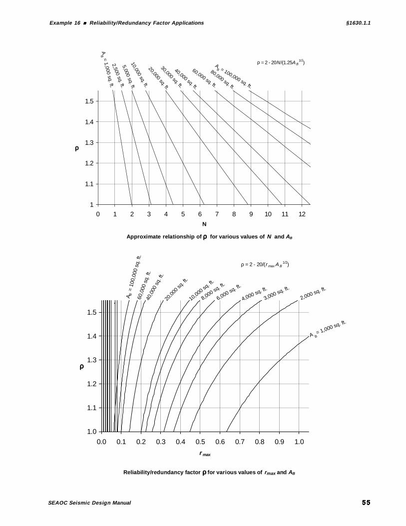
Example 16 Reliability/Redundancy Factor Applications §1630.1.1
SEAOC Seismic Design Manual
Approximate relationship of ρρρρ for various values of N and AB
Reliability/redundancy factor ρρρρ for various values of rmax and AB
40,0
00 s
q. ft
.
20,0
00 sq
. ft.
10,000 sq. ft
.
8,000 sq. ft
.
6,000 sq. ft.
4,000 sq. ft.
3,000 sq. ft.
2,000 sq. ft.
A B = 1,000 sq. ft.
60,0
00 s
q. ft
.
A B =
100
,000
sq.
ft.
1.0
1.1
1.2
1.3
1.4
1.5
0.0 0.1 0.2 0.3 0.4 0.5 0.6 0.7 0.8 0.9 1.0
r max
ρρρρ
ρ = 2 - 20/(r max A B1/2)
AB = 1,000 sq. ft.
2,500 sq. ft.
10,000 sq. ft.20,000 sq. ft.
30,000 sq. ft.
40,000 sq. ft.
60,000 sq. ft.
80,000 sq. ft.
AB = 100,000 sq. ft.
5,000 sq. ft.
1
1.1
1.2
1.3
1.4
1.5
0 1 2 3 4 5 6 7 8 9 10 11 12
N
ρρρρ
ρ = 2 - 20N/(1.25A B1/2)

§1630.1.3 Example 17 P∆∆∆∆ Effects
SEAOC Seismic Design Manual
2
∆ $%(4''(
In highrise building design, important secondary moments and additional story driftscan be developed in the lateral force-resisting system by ∆P effects. ∆P effects arethe result of the axial load P in a column being “moved” laterally by horizontaldisplacements, thereby causing additional “secondary” column and girder moments.The purpose of this example is to illustrate the procedure that must be used to checkthe overall stability of the frame system for such effects.
A 15-story building has a steel special moment-resisting frame (SMRF). Thefollowing information is given:
Zone 45.8=R
At the first story,kips 643,8==Σ WD
kips 850,3=ΣLkips 0.363042.01 === WVV
ft 201 =h
Story drift = in. 72.0003.0 11 ==∆ hS
Determine the following:
∆P criteria for the building.
Check the first story for ∆P requirements.
Calculations and Discussion Code Reference
∆P criteria for the building. §1630.1.3
∆P effects must be considered whenever the ratio of secondary moments to primarymoments exceed 10 percent. As discussed in Section C105.1.3 of the 1999 SEAOCBlue Book Commentary, this ratio is defined as a stability coefficient θ :
xx
sxxx
hV
P ∆=θ
h1 = 20'

Example 17 P∆∆∆∆ Effects §1630.1.3
SEAOC Seismic Design Manual
where
xθ = stability coefficient for story x
xP = total vertical load (unfactored) on all columns in story x
sx∆ = story drift due to the design base shear
xV = design shear in story x
xh = height of story x
∆P effects must be considered when 10.0>θ
An alternative approach is to check story drift.
In Seismic Zones 3 and 4, ∆P effects need not be considered for SMRF buildingswhenever the story drifts satisfy the following criterion:
00235.5.8
02.002.0 ==≤∆
Rhs §1630.1.3
Therefore, when the story drift in a given story of an SMRF is less than or equal to.00235, ∆P effects need not be considered for that story.
Check ∆P requirements for the first story.
The first story drift ratio is
003.0003.0
1
1
1
1 ==∆
h
h
hS
Check drift criteria
00235.003. >
Section 1630.1.3 requires that the total vertical load 1P at the first story be consideredas the total dead ( )DΣ plus floor live ( )LΣ and snow ( )S load above the first story.
These loads are unfactored for determination of ∆P effects.
SLDP +Σ+Σ=1
using 0=S for the building site
493,12850,3643,81 =+=P kips

§1630.1.3 Example 17 P∆∆∆∆ Effects
SEAOC Seismic Design Manual
100.0103.0)0.363(
)003.0)(493,12(
1
1
11
111 >==
∆=θ
h
h
hV
P S
considered bemust effects ∆∴P
Commentary
The 1999 SEAOC Blue Book Commentary, in Section C105.1.3, provides anacceptable ∆P analysis: for any story x where ∆P effects must be considered, the
story shear xV must be multiplied by a factor ( )da+1 , where θ−
θ=1da , and the
structure is to be re-analyzed for the seismic force effects corresponding to theaugmented story shears. Also, some computer programs include the option to include
∆P effects. The user should verify that the particular method is consistent with therequirements of this §1630.1.3.

Example 18 Design Base Shea §1630.2.1
SEAOC Seismic Design Manual
3
# 8 " $%(4'&'
Find the design base shear for a 5-story steel special moment-resisting frame buildingshown below, given the following information:
Z = 0.4Seismic source type = BDistance to seismic source = 5 kmSoil profile type = CS
I = 1.0R = 8.5W = 1,626 kips
In solving this example, the following steps are followed:
Determine the structure period.
Determine the seismic coefficients aC and vC .
Determine base shear.
Calculations and Discussion Code Reference
Determine the structure period. §1630.2.2
Method A to be used. tC for steel moment-resisting frames is 0.035.
( ) ( ) .sec 75.60 035. 43
43
=== nt hCT (30-8)
Determine the seismic coefficients aC and vC §1628
From Table 16-Q for soil profile type CS and Z = .4
aa NC 40.=
From Table 16-R for soil profile type CS and Z = .4
vv NC 56.=
Find aN and vN from Tables 16-S and 16-T, respectively, knowing that the seismic
source type is B and the distance 5 km.
0.1=aN
60'

§1630.2. 1 Example 18 Design Base Shear
SEAOC Seismic Design Manual
2.1=vN
Therefore
( ) 40.0.1 40. ==aC
( ) 672.2.1 56. ==vC
Determine base shear. §1630.2.1
The total base shear in a given direction is determined from:
kips 4.171626,175.5.8
0.1672. =×××== W
RT
ICV v (30-4)
However, the code indicates that the total design base shear need not exceed:
kips 3.191626,15.8
0.14.05.25.2=×××== W
R
ICV a (30-5)
Another requirement is that total design base shear cannot be less than:
kips 5.71626,10.140.11.011.0 =×××== IWCV a (30-6)
In Zone 4, total base shear also cannot be less than:
kips 5.73626,15.8
0.12.14.08.08.=××××== W
R
IZNV v (30-7)
In this example, design base shear is controlled by Equation 30-4.
kips 4.171=∴V
Commentary
The near source factor Na used to determine Ca need not exceed 1.1 if the conditions
of §1629.4.2 are met.

Example 19 Structure Period Using Method §1630.2.2
SEAOC Seismic Design Manual
-
" # 9 7 $%(4'&'&
Determine the period for each of the structures shown below using Method A.Method A uses the following expression to determine period:
( ) 43
nt hCT = (30-8)
The coefficient tC is dependent on the type of structural system used. The code also
allows use of Method B for the analytical evaluation of the fundamental period. Itshould be noted that the computation of the fundamental period using Equation 30-10of this method can be cumbersome and time consuming. With widespread use ofpersonal computers and structural analysis software in practice, a computer candetermine periods much more easily than through use of Equation 30-10.
Steel special moment-resisting frame (SMRF) structure.
Concrete special moment-resisting frame (SMRF) structure.
Steel eccentric braced frame (EBF).
Masonry shear wall building.
Tilt-up building.
Calculations and Discussion Code Reference
Steel special moment-resisting frame (SMRF) structure. §1630.2.2
Height of the structure above itsbase is 96 feet. The additional 22-footdepth of the basement is notconsidered in determining nh
for period calculation.
035.0=tC
( ) ( ) sec. 07.196 035.0 43
43
=== nt hCT
Grade
22′
96′
Basement
Superstructure

§1630.2.2 Example 19 Structure Period Using Method A
SEAOC Seismic Design Manual
Concrete special moment-resisting frame (SMRF) structure. §1630.2.2
Height of tallest part of the building is 33 feet,and this is used to determine period. Roofpenthouses are generally not considered indetermining nh , but heights of setbacks are
included. However, if the setback representsmore than a 130 percent change in the lateralforce system dimension, then there is avertical geometric irregularity (Table 16-L).For taller structures, more than five stories or65 feet in height, dynamic analysis is requiredfor this type of irregularity.
030.0=tC
( ) ( ) .sec 41.033 030.0 43
43
=== nt hCT
Steel eccentric braced frame (EBF). §1630.2.2
EBF structures use the Ct for the
category “all other buildings.”
030.0=tC
( ) ( ) .sec 51.044 030.0 43
43
=== nt hCT
Masonry shear wall building. §1630.2.2
44'
29'
Front wall elevation
10' Typ.
60'
10' Typ.
Back wall elevatio
29'
45'
33′
22′
Setback

Example 19 Structure Period Using Method §1630.2.2
SEAOC Seismic Design Manual
For this structure, Ct may be taken as 0.020, the value for “all other buildings,” or its
value may be computed from the following formula:
ct
AC
1.0= §1630.2.2
where
∑
+=
2
2.0n
eec h
DAA (30-9)
Solving for De and Ae for front and back walls, respectively, the value of Ac can be
determined.
Front Wall
Nominal CMU wall thickness = 8”
Actual CMU wall thickness = 7.625”
ft 29=nh
ft 60=eD
( ) ftsq 7.1212
63.7 '104'60 =−= xxAe
07.2=n
e
h
D
Back Wall
ft 45=eD
( ) ftsq 5.912
63.7 '103'45 =−= xxAe
55.1=n
e
h
D
Using Equation 30-9, the value of Ac is determined. Note that the maximum value of
De /hn that can be used is 0.9.
( )[ ] ( )[ ] 4.22 9.02.0 5.9 9.02.0 7.12 22 =+++=cA sq ft

§1630.2.2 Example 19 Structure Period Using Method A
SEAOC Seismic Design Manual
021.04.22
1.0 ==tC
( ) .sec26.029 021.0)( 43
43
=== nt hCT
Alternately, the period can be determined using Ct = .020 for “all other buildings”
( ) .sec25.029 020.0)( 43
43
=== nt hCT
Under current code provisions, either period can be used to determine base shear.
Tilt-up building.
Consider a tilt-up building 150 ft x 200 ft in plan that has a panelized wood roof andthe typical wall elevation shown below.
020.0=tC
( ) .sec19.020 02.0)( 43
43
=== nt hCT
This type of structural system has relatively rigid walls and a flexible roof diaphragm.The code formula for period does not take into consideration the fact that the realperiod of the building is highly dependent on the roof diaphragm construction. Thus,the period computed above is not a good estimate of the real fundamental period ofthis type of building. It is acceptable, however, for use in determining design baseshear.
It should be noted that the actual diaphragm response is approximately taken intoaccount in the design process by increased seismic force provisions on wall anchorsand by the limit of R = 4 for calculation of diaphragm loads as required under§1633.2.9.3.
20' 15' typ.
8' typ.20' typ.
Typical wall elevatio
150'
3' typ.

Example 20 Simplified Design Base Shea §1630.2.3
SEAOC Seismic Design Manual
&4
" # 8 " $%(4'&'(
Determine the design base shear and the design lateral forces for a three-story woodstructural panel wall building using the simplified design base shear. The soil profiletype for the site is unknown. The following information is known:
4.0=ZSeismic source type BDistance to seismic source = 5 km
5.5=Rk750=W
In solving this example, the following steps are followed:
Check applicability of simplified method.
Determine base shear.
Determine lateral forces at each level.
Calculations and Discussion Code Reference
Check applicability of simplified method. §1629.8.2
Light frame construction not more than three stories, or other buildings not more thantwo stories can use the simplified method.
∴ o.k.
Determine base shear. §1630.2.3
Because soil properties for the site are not known, a default/prescribed soil profilemust be used. Section 1630.2.3.2 requires that a Type DS soil profile be used in
seismic Zones 3 and 4.
0.1=aN Table 16-S
300k
300k
150k
Storyweight
3
2
1
Level
1 2 3
20'20'
12'
12'
12'

§1630.2. 3 Example 20 Simplif ied Design Base Shear
SEAOC Seismic Design Manual
( ) 44.00.1 44.044.0 === aa NC Table 16-Q
( )k180750)24.0(
5.5
75044.0 0.30.3==== W
R
CV a (30-11)
Determine lateral forces at each level. §1630.2.3.3
xxa
x wwR
CF 24.0
0.3== (30-12)
( ) k72300 24.01 ==F
( ) k72300 24.02 ==F
( ) k36150 24.03 ==F
Commentary
The following is a comparison of simplified base shear with standard design baseshear. The standard method of determining the design base shear is as follows:
WR
ICV a
5.2=
( )( ) ( ) kips 150750 2.02.0 5.5
0.1 44.0 5.2 ==== WW (30-12)
The distribution of seismic forces over the height of the structure is
( )
∑=
−=
n
iii
xxtx
hw
hwFVF
1
(30-15)
where
kips 150=− tFV since 0=tF in this example.

Example 20 Simplified Design Base Shea §1630.2.3
SEAOC Seismic Design Manual
Level x xh xw xx hwii
xx
hw
hw
Σ xF xx wF
3 36 ft 150 kips 5,400 k-ft 0.333 50.0 kips 0.33
2 24 300 7,200 0.444 66.7 0.22
1 12 300 3,600 0.222 33.3 0.11
=Σ iihw 16,200 =Σv 150.0
The design base shear V and the lateral force values xF at each level are all less than
those determined by the simplified method. The principal advantage of the simplifiedmethod is that there is no need to conform to the provisions listed in §1630.2.3.4,which are otherwise applicable.
Another advantage is that the value of the near-source factor aN used to determine
aC need not exceed:
1.3 if irregularities listed in §1630.2.3.2 are not present
and
1.1 if the conditions of §1629.4.2 are complied with
It should be noted that Section 104.8.2 of the 1999 SEAOC Blue Book has differentrequirements for applicability of the simplified method:
Single family two stories or less
Light frame up to three stories
Regular buildings up to two stories
Blue Book §105.2.3 allows the near source factor 0.1=aN for evaluation of aC .The Blue Book equation WCV a8.0= does not contain the R factor, which eliminates
the sometimes difficult problem of selecting the appropriate R value for smallbuildings that have complex and/or mixed lateral load resisting systems.

§1630.4.2 Example 21 Combination of Structural Systems: Vertical
SEAOC Seismic Design Manual
&
" "1 ! / $%(4'*'&
In structural engineering practice, it is sometimes necessary to design buildings thathave a vertical combination of different lateral force-resisting systems. For example,the bottom part of the structure may be a rigid frame and top part a braced frame orshear wall. This example illustrates use of the requirements of §1630.4.2 to determinethe applicable R values for combined vertical systems.
For the three systems shown below, determine the required R factor and relateddesign base shear requirements.
Calculations and Discussion Code Reference
Steel ordinary braced frame over steel SMRF.
This combined system falls under vertical combinations of §1630.4.2. Because therigid system is above the flexible system, Item 2 of §1630.4.2 cannot be used.Therefore, under Item 1 of §1630.4.2, the entire structure must use 6.5=R .
Concrete bearing wall over concrete SMRF.
Steel ordinary braced frameR = 5.6
Steel special moment-resisting frameR = 8.5
Concrete bearing wallR = 4.5
Concrete special moment-resisting frame R = 8.5

Example 21 Combination of Structural Systems: Ver tical §1630.4.2
SEAOC Seismic Design Manual
This combined system falls under vertical combinations of §1630.4.2. Because therigid portion is above the flexible portion, Item 2 of §1630.4.2 cannot be used.Therefore, under Item 1 of §1630.4.2, the entire structure must use 54.R = .
Concrete SMRF over a concrete building frame system.
Applicable criteria.This is a vertical combination of a flexible system over a more rigid system.Under §1630.4.2, Item 2, the two stage static analysis may be used, providedthe structures conform to §1629.8.3, Item 4.
Check requirements of §1629.8.3, Item 4:
1. Flexible upper portion supported on rigid lower portion. o.k.
2. Average story stiffness of lower portion is at least 10 times average story stiffnessof upper portion.
( ) k/in. 750,117510k/in. 000,10 => o.k.
3. Period of entire structure is not greater than 1.1 times period of upper portion.
( ) sec 61.055.1.1sec 56.0 =< o.k.
used be can 2 Item §1630.4.2, of Provisions ∴
Concrete building frame systemR = 5.5, ρ = 1.0Stiffness = 10,000 k/in.Tlower = 0.03 sec
Concrete SMRFR = 8.5, ρ = 1.5Avg. stiffness upper portion = 175 k/in.Tupper = 0.55 secTcombined = 0.56 sec
Shear walls

§1630.4.2 Example 21 Combination of Structural Systems: Vertical
SEAOC Seismic Design Manual
Design procedures for upper and lower structures.
Design the lower portion of thebuilding frame system for thecombined effects of the amplified
frameV force and the lateral forces due
to the base shear for the lower portionof the structure (using 5.5=R and
0.1=ρ for the lower portion).
( ) ( )lowerframebase VVV +=∴ Amplified
Amplified Vframe =
0155
5158
..
..Vframe = 1.03 Vframe
Vbase
Design upper SMRF usingR = 8.5 and ρ = 1.5
Vframe

Example 22 Combination of Structural Systems: Along Different Axes §1630.4.3
SEAOC Seismic Design Manual
&&
" "1 !
7# 7 $%(4'*'(
This example illustrates determination of R values for a building that has differentstructural systems along different axes (i.e., directions) of the building.
In this example, a 3-story building has concrete shear walls in one direction andconcrete moment frames in the other. Floors are concrete slab, and the building islocated in Zone 4. Determine the R value for each direction.
Lines A and D are reinforced concrete bearing walls: 5.4=R
Lines 1, 2 and 3 are concrete special moment-resisting frames: 5.8=R
Determine th R value for each direction.
Calculations and Discussion Code Reference
In Zones 3 and 4, the provisions of §1630.4.3 require that when a structure hasbearing walls in one direction, the R value used for the orthogonal direction cannot begreater than that for the bearing wall system.
∴ Use 5.4=R in both directions.
Typical floor plan
A D
1
2
3
B C
Shear wall

§1630.4.3 Example 22 Combination of Structural Systems: Along Different Axes
SEAOC Seismic Design Manual
Commentary
The reason for this orthogonal system requirement is to provide sufficient strengthand stiffness to limit the amount of out-of-plane deformation of the bearing wallsystem. A more direct approach would be to design the orthogonal system such thatthe M∆ value is below the value that would result in the loss of bearing wall
capacity.
The design loads for the special moment-resisting frames are calculated using5.4=R . However, the frame details must comply with the requirements for the5.8=R system.

Example 23 Combination of Structural Systems: Along Same Axis §1630.4.4
SEAOC Seismic Design Manual
&(
" "1 !
7# " 7 $%(4'*'*
Occasionally, it is necessary to have different structural systems in the samedirection. This example shows how the R value is determined in such a situation.
A one-story steel frame structure has the roof plan shown below. The structure islocated in Zone 4. Determine the R value for the N/S direction.
Lines 1 and 4 are steel ordinary moment-resisting frames: 5.4=R .
Lines 2 and 3 are steel ordinary braced frames: 6.5=R .
Determine th R value for the N/S direction.
Calculations and Discussion Code Reference
In Zones 2, 3, and 4, when a combination of structural systems is used in the samedirection, §1630.4.4 requires that the value of R used be not greater than the leastvalue of the system utilized.
∴ Use 54.R = for entire structure.
Roof plan
1
2
3
4
North

§1630.5 Example 24 Vertical Distr ibution of Force
SEAOC Seismic Design Manual
&*
/ , $%(4'0
A 9-story building has a moment resisting steel frame for a lateral force-resistingsystem. Find the vertical distribution of lateral forces xF . The following information
is given:
Zone 4k762,3=W
56.0=vC
R = 8.50.1=I
.sec06.1=Tk8.233=V
In solving this example, the following steps are followed:
Determine Ft.
Find Fx at each level.
Calculations and Discussion Code Reference
Determine Ft. §1630.5
This is the concentrated force applied at the top of the structure. It is determined asfollows. First, check that the tF is not zero.
0sec7.0.sec06.1 >∴>= tFT
( )( ) k3.178.233 06.1 07.007.0 === TVFt (30-14)
9
8
7
6
5
4
3
2
112'
20'
12'
12'
12'
12'
12'
12'
12'
1 2 3
27' 27'
214k
405k
405k
584k
422k
422k
440k
465k
Storyweight
405k
Level

Example 24 Vertical Distribution of Force §1630.5
SEAOC Seismic Design Manual
Find Fx at each level.
The vertical distribution of seismic forces is determined from Equation 30-15.
( )
∑=
−=
n
ii
xxtx
hw
hwFVF
1
(30-15)
where
( ) ( ) k5.2163.178.233 =−=− tFV
Since there are nine levels above the ground, 9=n . Therefore
∑=
=9
1
5.216
iii
xxx
hw
hwF
This equation is solved in the table below.
Level x xh xw xx hwii
xx
hw
hw
Σ xF xx wF
9 116 ft 214 kips 24,824 k-ft 0.103 22.3 + 17.3 = 39.6 kips 0.185
8 104 405 42,120 0.174 37.7 0.093
7 92 405 37,260 0.154 33.3 0.082
6 80 405 32,400 0.134 29.0 0.072
5 68 584 39,712 0.164 35.5 0.061
4 56 422 23,632 0.098 21.2 0.050
3 44 422 18,568 0.077 16.7 0.039
2 32 440 14,080 0.058 12.6 0.028
1 20 465 9,300 0.038 8.2 0.018
Σ =3,762 241,896 233.8
Commentary
Note that certain types of vertical irregularity can result in a dynamic response havinga load distribution significantly different from that given in this section. If thestructural system has any of the stiffness, weight, or geometric vertical irregularitiesof Type 1, 2, or 3 of Table 16-L, then Item 2 of §1629.8.4 requires that the dynamiclateral force procedure be used unless the structure is less than five stories or 65 feetin height. The configuration and final design of this structure must be checked forthese irregularities. Most structural analysis programs used in practice today performthis calculation, and it is generally not necessary to manually perform the calculationsshown above. However, it is recommended that these calculations be performed tocheck the computer analysis and to gain insight to structural behavior.

§1630.6 Example 25 Horizontal Distribution of Shear
SEAOC Seismic Design Manual
&0
: " $%(4'%
A single story building has a rigid roof diaphragm. Lateral forces in both directionsare resisted by shear walls. The mass of the roof can be considered to be uniformlydistributed, and in this example, the weight of the walls is neglected. In actualpractice, particularly with concrete shear walls, the weight of the walls should beincluded in the determination of the Center of Mass (CM). The following informationis given:
Design base shear: k100=V
Wall rigidities: k/in.300=AR
k/in.100=BR.k/in200== DC RR
Center of mass: ft 20ft 40 == mm yx
Determine the following:
Eccentricity and rigidity properties.
Direct shear in walls A and B.
Plan irregularity requirements.
Torsional shear in walls A and B.
Total shear in walls A and B.
A
D
B
C
Y
80'
X
Shear wall below
Roof diaphragm
40'
CR
e
CM
V = 100k
xR
xm = 40'yR ym
Roof plan

Example 25 Horizontal Distribution of Shea §1630.6
SEAOC Seismic Design Manual
Calculations and Discussion Code Reference
Eccentricity and rigidity properties. §1630.6
The rigidity of the structure in the direction of applied force is the sum of therigidities of walls parallel to this force.
k/in. 400100300 =+=+= BA RRR
The center of rigidity (CR) along the x and y axes are
( )ft. 20
'80=
+=
BA
BR
RR
Rx
( )ft20
04=
+′
=CD
DR
RR
Ry
eccentricity ft 202040 =−=−= Rm xxe
Torsional rigidity about the center of rigidity is determined as
( ) ( ) ( ) ( )2222 20206020 DCBA RRRRJ +++=
( ) ( ) ( ) ( ) ( ) 242222 ftk/in.106420 20020 20060 10020 300 ×=+++=
The seismic force V applied at the CM is equivalent to having V applied at the CRtogether with a counter-clockwise torsion T. With the requirements for accidentaleccentricity acce , the total shear on walls A and B can be found by the addition of the
direct and torsional load cases:
CR
V
VD,A VD,B
Direct shear contribution
D
A B
C
20'20'
20'
60'
VT,B
BA
T = V (e ± eacc)
VT,A
Torsional shear contributio
VT,D
VT,C
D
C
CR

§1630.6 Example 25 Horizontal Distribution of Shear
SEAOC Seismic Design Manual
Direct shear in walls A and B.
kips 0.75100100300
300)(, =×
+=×
+= V
RR
RV
BA
AAD
kips 0.25100100300
100)(, =×
+=×
+= V
RR
RV
BA
BBD
Plan irregularity requirements.
The determination of torsional irregularity, Item 1 in Table 16-M, requires theevaluation of the story drifts in walls A and B. This evaluation must includeaccidental torsion due to an eccentricity of 5 percent of the building dimension.
teacc f0.4)'80(05.0 ==
The corresponding initial most severe torsional shears 'V using ft 0.4=acce are:
kips 0.151064
)300( )20( )420( 100)( )( )(4,
' =×
−=−
=J
RxeeVV ARacc
AT
kips 5.221064
)100( )60( )420( 100)( )80( )(4,
' =×
+=−+
=J
RxeeVV BRacc
BT
Note: these initial shears may need to be modified if torsional irregularity exists andthe amplification factor 0.1>xA .
The initial total shears are:
sVVV ATADA kip 0.600.150.75,'
,'' =−=−=
(Torsional shears may be subtracted if they are due to the reduced eccentricity accee− )
kips 5.475.220.25,'
,'' =+=+= BTBDB VVV
The resulting displacements 'δ , which for this single story building are also the storydrift values, are:
in. 20.0300
0.60'' ===δ
A
AA
R
V

Example 25 Horizontal Distribution of Shea §1630.6
SEAOC Seismic Design Manual
in. 48.0100
5.47'' ===δ
B
BB
R
V
in. 34.02
48.020.0 =+=δavg
in. 48.0' =δ=δ Bmax
2.141.134.0
48.0 >==δδ
avg
max
∴ Torsional irregularity exists.
Section 1630.7 requires the accidental torsion amplification factor,
0.338.1)34.0( 2.1
48.0
2.1
22
<=
=
δ
δ=
avg
maxxA (30-16)
Torsional shears in walls A and B.
The final most severe torsional shears are determined by calculating the newaccidental eccentricity and using this to determine the torsional shears
'54.5)0.4( )38.1()0.4( === xacc Ae
kips 6.131064
)300( )20( )54.520( 1004, =
×−=ATV
kips 9.231064
)100( )60( )54.520( 1004, =
×+=BTV
Total shear in walls A and B.
Total shear in each wall is the algebraic sum of the direct and torsional shearcomponents.
kips 4.616.130.75,, =−=−= ATADA VVV
kips 9.489.230.25,, =+=+= BTBDB VVV

§1630.6 Example 25 Horizontal Distribution of Shear
SEAOC Seismic Design Manual
Commentary
Section 1630.7 requires that “the most severe load combination for each element shallbe considered for design.” This load combination involves the direct and torsionalshears, and the “most severe” condition is as follows:
1. For the case where the torsional shear has the same sense, and is therefore addedto the direct shear, the torsional shear shall be calculated using actual eccentricityplus the accidental eccentricity so as to give the largest additive torsional shear.
2. For the case where the torsional shear has the opposite sense to that of the directshear and is to be subtracted, the torsional shear shall be based on the actualeccentricity minus the accidental eccentricity so as to give the smallestsubtractive shear.

Example 26 Horizontal Torsional Moments §1630.7
SEAOC Seismic Design Manual
&%
: 9 $%(4'2
This example illustrates how to include the effects of accidental eccentricity in thelateral force analysis of a multi-story building. The structure is a five-story reinforcedconcrete building frame system. A three-dimensional rigid diaphragm model has beenformulated per §1630.1.2 for the evaluation of element actions and deformations dueto prescribed loading conditions. Shear walls resist lateral forces in both directions.
The lateral seismic forces xF in the north-south direction, structure dimensions, and
accidental eccentricity acce for each level x are given below:
Level x xF xL cxx xacc Le 050.=
5 110.0 kips 80.0 ft 24.2 ft ± 4.0 ft
4 82.8 80.0 25.1 ± 4.0
3 65.1 80.0 27.8 ± 4.0
2 42.1 80.0 30.3 ± 4.0
1 23.0 80.0 31.5 ± 4.0
In addition, for the given lateral seismic forces xF a computer analysis provides the
following results for the second story. Separate values are given for the application ofthe forces xF at the centers of mass and the xL.050± displacements as required by
§1630.6.
2 3 4 51
4 @ 20' = 80'
3 @
20'
= 6
0'B
C
A
D
A
B
Floor plan at Level x
Shear wall, typ.
N
CMx
Fx
xc

§1630.7 Example 26 Horizontal Torsional Moments
SEAOC Seismic Design Manual
Force xF Position
2cx accc ex −2 accc ex +2
Wall shear AV 185.0 k 196.0 k 174.0 k
Wall shear BV 115.0 k 104.0 k 126.0 k
Story drift Aδ∆ 0.35" 0.37" 0.33"
Story drift Bδ∆ 0.62" 0.56" 0.68"
Level 2 displacement Aδ 0.80" 0.85" 0.75"
Level 2 displacement Bδ 1.31" 1.18" 1.44"
For the second story find the following:
Maximum force in shear walls A and B.
Check if torsional irregularity exists.
Determine the amplification factor Ax.
New accidental torsion eccentricity.
Calculations and Discussion Code Reference
Maximum force in shear walls A and B.
The maximum force in each shear wall is a result of direct shear and the contributiondue to accidental torsion. From the above table, it is determined that
k0.196=AV
k0.126=BV
Check if torsional irregularity exists.
The building is L-shaped in plan. This suggests that it may have a torsion irregularityType 1 of Table 16-M. The following is a check of the story drifts.
in. 68.0=δ∆ max
in. 51.02
33.068.0 =+=δ∆ avg
2.133.151.0
68.0
2.1>==
δ∆δ∆
avg
max
existsty irregulari Torsional ∴

Example 26 Horizontal Torsional Moments §1630.7
SEAOC Seismic Design Manual
Determine the amplification factor Ax.
Because a torsional irregularity exists, §1630.7 requires that the second storyaccidental eccentricity be amplified by the following factor.
2
2.1
δ
δ=
avg
maxxA (30-16)
where in. 44.1=δ=δ Bmax
The average story displacement is computed as
in. 10.12
75.044.1 =+=δavg
19.1)10.1( )2.1(
44.12
2 =
=A
New accidental torsion eccentricity.
Since 2A (i.e., xA for the second story) is greater than unity, a second analysis for
torsion must be done using the new accidental eccentricity.
ft 76.4)'0.4( )19.1( ==acce
Commentary
Example calculations were given for the second story. In practice, each story requiresan evaluation of the most severe element actions and a check for the torsionalirregularity condition.
If torsional irregularity exists and xA is greater than one at any level (or levels), then
a second torsional analysis must be done using the new accidental eccentricities.However, it is not necessary to find the resulting new xA values and repeat the
process a second or third time (until the xA iterates to a constant or reaches the limitof 3.0). The results of the first analysis with the use of xA are sufficient for design
purposes.
While this example involved the case of wall shear evaluation, the same procedureapplies to the determination of the most severe element actions for any other lateralforce-resisting system having rigid diaphragms.
When the dynamic analysis method of §1631.5 is used, rather than static forceprocedure of §1630.2, the following equivalent static force option may be used in lieu

§1630.7 Example 26 Horizontal Torsional Moments
SEAOC Seismic Design Manual
of performing the two extra dynamic analyses for mass positions at ( )xcx Lx 05.0± as
per §1631.5.6:
1. Perform the dynamic analysis with masses at the center of mass, and reduceresults to those corresponding to the required design base shear.
2. Determine the xF forces for the required design base shear, and apply pure
torsion couple loads ( )xx LF 05.0 at each level x . Then add the absolute value of
these couple load results to those of the reduced dynamic analysis.

Example 27 Elements Supporting Discontinuous Systems §1630.8.2
SEAOC Seismic Design Manual
&2
"# "1 $%(4'3'&
A reinforced concrete building has the lateral force-resisting system shown below.Shear walls at the first floor level are discontinuous between Lines A and B and LinesC and D. The following information is given:
Zone 4Concrete shear wall building frame system: R = 5.5 and 8.2=Ωo Table 16-N
Office building live load: 5.01 =f §1612.4Axial loads on column C: kips 100kips 20kips 40 === hELD
Determine the following for column C:
Required strength.
Detailing requirements.
Calculations and Discussion Code Reference
This example demonstrates the loading criteria and detailing required for elementssupporting discontinued or offset elements of a lateral force-resisting system.
Column C24" x 24"
f'c = 4000 psi
A C DB
4
3
2
Level
1
Shear wall
12'
12'
12'
12'

§1630.8.2 Example 27 Elements Support ing Discontinuous Systems
SEAOC Seismic Design Manual
Required strength. §1630.8.2.1
Because of the discontinuous configuration of the shear wall at the first story, the firststory columns on Lines A and D must support the wall elements above this level.Column “C” on Line D is treated in this example. Because of symmetry, the columnon Line A would have identical requirements.
Section 1630.8.2 requires that the column strength be equal to or greater than
mu ELfDP 0.12.1 1 ++= (12-17)
mu EDP 0.19.0 ±= (12-18)
where
( ) kips 2801008.2 ==Ω= hom EE (30-2)
Substituting the values of dead, live and seismic loads
( ) ( ) kips 338280205.040 2.1 =++=uP compression, and
( ) ( ) kips 2442800.1409.0 −=−=uP tension
Detailing requirements. §1630.8.2.2
The concrete column must meet the requirements of §1921.4.4.5. This sectionrequires transverse confinement tie reinforcement over the full column height if
( ) ( )kips 230
10
ksi 424
10
' 2
==> cgu
fAP
kips 230338>=uP
height full over the required ist Confinemen ∴
Commentary
To transfer the shears from walls A-B and C-D to the first story wall B-C, collectorbeams A-B and C-D are required at Level 1. These would have to be designedaccording to the requirements of §1633.2.6.
The load and detailing requirements of §1630.8.2, Elements SupportingDiscontinuous Systems, apply to the following vertical irregularities and verticalelements:

Example 27 Elements Supporting Discontinuous Systems §1630.8.2
SEAOC Seismic Design Manual
1. Discontinuous shear wall. Thewall at left has a Type 4 verticalstructural irregularity.
2. Discontinuous column. This framehas a Type 4 vertical structuralirregularity.
3. Out-of-plane offset. The wall onLine A at the first story isdiscontinuous. This structure has aType 4 plan structural irregularity,and §1620.8.2 applies to thesupporting columns. The portionof the diaphragm transferringshear (i.e., transfer diaphragm) tothe offset wall must be designedfor shear wall detailingrequirements, and the transferloads must use thereliability/redundancy factor ρ for
the vertical-lateral-force-resistingsystem.
It should be noted that for any of the supporting elements shown above, the loaddemand mE of Equation (30-2) need not exceed the maximum force that can be
transferred to the element by the lateral force-resisting system.
Transferdiaphragm
VE
Offset wall Supporting columns
Discontinuedwall
Column
Transfergirder
A
B
C

§1630.8.2 Example 28 Elements Support ing Discontinuous Systems
SEAOC Seismic Design Manual
&3
"# "1 $%(4'3'&
This example illustrates the application of the requirements of §1630.8.2 for theallowable stress design of elements that support a discontinuous lateral force-resistingsystem.
In this example, a light-framed wood bearing wall building with plywood shearpanels has a Type 4 vertical irregularity in one of its shear walls, as shown below.
The following information is given:
Zone 45.5=R
8.2=Ωo
5.01 =f
Axial loads on the timber column under thediscontinuous portion of the shear wall are:
Dead kips 0.6=D
Live kips 0.3=L
Seismic kips 0.7±=hE
Determine the following:
Applicable load combinations.
Required column design strength.
Calculations and Discussion Code Reference
Applicable load combinations.
For vertical irregularity Type 4, §1630.8.2.1 requires that the timber column have the“design strength” to resist the special seismic load combinations of §1612.4. This isrequired for both allowable stress design and strength design. These loadcombinations are:
mELfD 0.12.1 1 ++ (12-17)
mED 0.19.0 ± (12-18)
Timber column
Light framed wallwith plywoodsheathing

Example 28 Elements Supporting Discontinuous Systems §1630.8.2
SEAOC Seismic Design Manual
Required column design strength.
In this shear wall, the timber column carries only axial loads. The appropriate dead,live and seismic loads are determined as:
kips 0.6=D
kips 0.3=L
( ) kips 6.190.78.2 ==Ω= hom EE (30-2)
For the required “design strength” check, both Equations (12-17) and (12-18) must bechecked.
mELfDP ++= 12.1 (12-17)
( ) ( ) kips 3.286.190.35.00.62.1 =++=P
mEDP 0.19.0 ±= (12-18)
( ) ( ) kips 2.14orkips 0.256.190.10.69.0 −=±=P
Commentary
For allowable stress design, the timber column must be checked for a compressionload of kips 3.28 and a tension load of kips 2.14 . In making this “design strength”check, §1630.8.2.1 permits use of an allowable stress increase of 71. and a resistancefactor, φ , of 01. . The 71. increase is not to be combined with the one-third increase
permitted by §1612.3.2, but may be combined with the duration of load increase33.1=DC given in Table 2.3.2 of Chapter 23, Division III. The resulting “design
strength” ( )( )( )33.10.17.1= (allowable stress). This also applies to the mechanical
hold-down element required to resist the tension load.
The purpose of the “design strength” check is to check the column for higher and,hopefully, more realistic loads that it will be required to carry because of thediscontinuity in the shear wall at the first floor. This is done by increasing the normalseismic load in the column, hE , by the factor 8.2=Ωo .

§1630.8.3 Example 29 At Foundation
SEAOC Seismic Design Manual
&-
7 , $%(4'3'(
Foundation reports usually provide soil bearing pressures on an allowable stressdesign basis while seismic forces in the 1997 UBC, and most concrete design, are ona strength design basis. The purpose of this example is to illustrate footing designunder this situation.
A spread footing supports a reinforced concrete column. The soil classification at thesite is sand (SW). The following information is given:
Zone 40.1=ρ for structural system
ft-k15k80 == DD MP
ft-k 6k30 == LL MP
ft-k 210k30k40 ±==±= EEE MVPSnow load 0=S
Find the following:
Determine the design criteria and allowable bearing pressure.
Determine footing size.
Check resistance to sliding.
Determine soil pressures for strength design of the footing section.
Calculations and Discussion Code Reference
Determine the design criteria and allowable bearing pressure. §1630.8.3
The seismic force reactions on the footing are based on strength design. However,§1629.1 states that allowable stress design may be used for sizing the foundationusing the load combinations given in §1612.3. Here it is elected to use the alternatebasic load combinations of §1612.3.2.
SLD ++ (12-12)
4.1
ELD ++ (12-13)
4.19.0
ED ± (12-16-1)
Because foundation investigation reports for buildings typically specify bearingpressures on an allowable stress design basis, criteria for determining footing size arealso on this basis.
P
M
V
2'
4'
Grade

Example 29 At Foundation §1630.8.3
SEAOC Seismic Design Manual
The earthquake loads to be resisted are specified in §1630.1.1 by Equation 30-1.
vh EEE +ρ= (30-1)
Since Ev = 0 for allowable stress design, Equation 30-1 reduces to
( ) hh EEE 0.1=ρ=
Table 18-1-A of §1805 gives the allowable foundation pressure, lateral bearingpressure, and the lateral sliding friction coefficient. These are default values to beused in lieu of site-specific recommendations given in a foundation report for thebuilding. They will be used in this example.
For the sand (SW) class of material and footing depth of 4 feet, the allowablefoundation pressure ap is
( )( )( ) ksf 40.250.1 2.0 ft 1ft 450.1 =−+=ap Table 18-1-A and Footnote 2
A one-third increase in ap is permitted for the load combinations that include
earthquake load.
Determine footing size.
The trial design axial load and moment will be determined for load combination ofEquation (12-13) and then checked for the other combinations.
kips 6.1384.1
403080
4.14.1=++=++=++= E
LDaP
PPE
LDP (12-13)
ft-k 0.1714.1
210615
4.14.1=++=++=++= E
LDaM
MME
LDM (12-13)
Select trial footing size.
Try 9 ft x 9 ft footing size, B = L = 9 ft
332
2 ft 5.1216
9
6,ft 81 ===== BL
SBLA
Calculated soil pressures due to axial load and moment
ksf 12.341.171.15.121
0.171
81
6.138 =+=+=+=S
M
A
Pp aa
Check bearing pressure against allowable with one-third increase,

§1630.8.3 Example 29 At Foundation
SEAOC Seismic Design Manual
( ) ,ksf 20.340.233.133.1ksf 12.3 ==< ap o.k.
Check for the load combination of Equation (12-16-1).
( ) kips 4.43orkips 6.1004.1
40809.0
4.19.0
4.19.0 =±=±=±= E
DaP
PE
DP (12-16-1)
( ) ft-k 5.136orft-k 5.1634.1
210159.0
4.19.0
4.19.0 =±=±=±= E
DaM
ME
DM
(12-16-1)
Eccentricity ft 15.3ft, 15.4.43
ft-k 5.136orft, 63.1
6.100
ft-k 5.163 =∴==== eP
Me
a
a governs.
Check for uplift.
ft 5.16
9
6==> L
e (where 6
L is the limit of the kern area)
Since ,..e 51153 >= there is partial uplift, and a triangular pressure distribution isassumed to occur.
For the footing free-body:
( )Bap
RP pa 32
==
pR must be co-linear with aP
such that the length of thetriangular pressure distributionis equal to a3 .=pR Pressure resultant
The load combination 4.1
9.0E
D − , with kips 4.43=aP and ft-k 5.136=aM (12-10)
governs bearing pressure
ft 35.115.35.42
=−=−= eB
a
Pa
p
e a
4.5'4.5'
Center line
3a
a
Rp

Example 29 At Foundation §1630.8.3
SEAOC Seismic Design Manual
( )Bap
Pa 32
=
or
( ) ( )( ) ksf 20.333.1ksf 38.20.935.1
14.43
3
21
3
2 =<=
=
= aa p
aBPp o.k.
If p had been greater than ap33.1 , the footing size would have to be increased.
Finally, check the gravity load combination (12-12) for ksf 2.3=< app .
kips 1103080 =+=+=+= LDa PPLDP (12-12)
ft-k 21615 =+=+=+= LDa MMLDM (12-12)
ksf, 2.3ksf 53.15.121
21
81
110 <=+=+=S
M
A
Pp aa o.k.
All applicable load combinations are satisfied, therefore a 9ft x 9ft footing isadequate.
Check resistance to sliding.
Unless specified in the foundation report for the building, the friction coefficient andlateral bearing pressure for resistance to sliding can be determined from Table18-1-A. These values are:
Friction coefficient 25.0=µ Table 18-1-A
Lateral bearing resistance ×= psf 150Lp depth below grade Table 18-1-A
Assume the footing is 2 feet thick with its base 4 feet below grade. Average
resistance on the 2 feet deep by 9 feet wide footing face is psf 4502
600300 =+.
ksf 45.0psf 450 ==Lp
Load combination of Equation (12-16-1) willbe used because it has the lowest value ofvertical load DPD 9.09.0 = ). The vertical and
lateral loads to be used in the slidingresistance calculations are:
( ) kips 7280 9.09.0 === DPPFace of footing
2'
2'
300 psf
600 psf

§1630.8.3 Example 29 At Foundation
SEAOC Seismic Design Manual
Lateral load = kips 4.214.1
30
4.1==EV
The resistance due to friction is
( ) ( ) kips 0.1825.072 ==µP
The resistance from lateral bearing is
( ) kips 1.892 45.0area)(face =′×′=Lp
The total resistance is then the sum of the resistance due to friction and the resistancedue to lateral bearing pressure.
Total resistance = kips, 4.211.261.80.18 >=+ o.k.
occursslidingNo∴
Determine soil pressures for strength design of footing section.
To obtain the direct shear, punching shear, and moments for the strength design ofthe reinforced concrete footing section, it is necessary to compute the upward designsoil pressure on the footing due to factored strength loads:
LfED 10.12.1 ++ (12-5)
ED 0.19.0 ± (12-6)
The section design must have the capacity to resist the largest moments and forcesresulting from these load combinations.
Soil pressure due to load combination LfED 10.12.1 ++ .
5.01 =f §1612.2.1
( ) ( ) ( ) kips 15130 5.040 0.180 2.15.00.12.1 =++=++= LEDu PPPP (12-5)
( ) ( ) ( ) ft-k 2316 5.0210 0.115 2.15.00.12.1 =++=++= LEDu MMMM (12-5)

Example 29 At Foundation §1630.8.3
SEAOC Seismic Design Manual
Eccentricity ft 53.1151
231===u
u
P
Me
ft 5.16
9
6==> L
e
Therefore partial uplift occurs.
ft 97.253.15.45.4 ===−= ea
( ) ( )( ) ksf 77.30.9 97.2
1 151
3
21
3
2 =
=
=
aBPp u
Soil pressure due to load combination ED 0.19.0 ± :
( ) ( ) kips 32orkips 11240 0.180 9.00.19.0 =±=±= EDu PPP (12-6)
( ) ( ) ft-k 5.196orft-k 5.223210 0.115 9.00.19.0 =±=±= EDu MMM (12-6)
Compute pressure load due to kips 112=uP and ft-k 5.223=uM
Eccentricity ft 00.2112
5.223 ===u
u
P
Me
ft 5.16
=> Le
therefore partial uplift occurs.
ft 50.20.25.45.4 =−=−= ea
( ) ( )( ) ksf 32.30.950.2
1 112
3
21
3
2 =
=
=
aBPp u
The footing pressure is less than that for the combination of LfED 10.12.1 ++ .
Therefore the LfED 10.12.1 ++ combination governs. Note that the resulting direct
shear, punching shear, and moments must be multiplied by 1.1 per Exception 1 of§1612.2.1. (Note: At the time of publication, the 1.1 factor is under consideration forchange to 1.0).
Note also that the value of p due to the strength design factored loads need not be
less than ksf, 20.333.1 =ap since it is used as a load for concrete section design
rather than for determining footing size.
Face of column
3a = 8.91'
p = 3.77 ksf
p = 3.32 ksf
3a = 7.50'
Face of column

§1630.9 Example 30 Dri
SEAOC Seismic Design Manual
(4
$%(4'-
A four-story special moment-resisting frame (SMRF) building has the typical floorplan as shown below. The elevation of Line D is also shown, and the followinginformation is given:
Zone 40.1=I5.8=R
8.2=Ωo
sec 60.0=T
The following are the design level response displacements S∆ (total drift) for the
frame along Line D. These values include both translational and torsional (withaccidental eccentricity) effects. As permitted by §1630.10.3, S∆ has been determined
due to design forces based on the unreduced period calculated using Method B.
Level ∆S
4 1.51 in
3 1.03
2 .63
1 .30
Typical floor plan
A B C D
Seismic force
4
3
2
1
Level
Elevation of Line D
12'
12'
12'
12'
∆S Deflected shape

Example 30 Dri §1630.9
SEAOC Seismic Design Manual
For the frame on Line D, determine the following:
Maximum inelastic response displacements M∆ .
Story drift in story 3 due to M∆ .
Check story 3 for story drift limit.
Calculations and Discussion Code Reference
Maximum inelastic response displacements M∆ . §1630.9.2
These are determined using the S∆ values and the R-factor
( )( ) SSSM R ∆=∆=∆=∆ 95.5 5.8 7.07.0 (30-17)
ThereforeLevel ∆S ∆M
4 1.51 in 8.98 in
3 1.03 6.12
2 0.63 3.75
1 0.30 1.79
Story drift in story 3 due to M∆ . §1630.10
Story 3 is located between Levels 2 and 3. Thus
M∆ drift = .in 37.275.312.6 =−
Check story 3 for story drift limit. §1630.10.2
For structures with a fundamental period less than 0.7 seconds, §1630.10.2requires that the M∆ story drift not exceed 0.025 times the story height.
For story 3
Story drift using in. 37.2=∆ M
Story drift limit ( ) in. 37.2in 60.3144025. >==
limits within isdrift Story ∴

§1630.10 Example 31 Story Drift Limitations
SEAOC Seismic Design Manual
(
"1 $%(4'4
For the design of new buildings, the code places limits on story drifts. The limits arebased on the maximum inelastic response displacements and not the design levelresponse displacements determined from the design base shear of §1630.2.
In the example given below, a four-story steel special moment-resisting frame(SMRF) structure has the design level response displacements S∆ shown. These
have been determined according to §1630.9.1 using a static, elastic analysis.
Zone 4T = 0.60 sec.R = 8.5
Determine the following:
Maximum inelastic response displacements.
Compare story drifts with the limit value.
Calculations and Discussion Code Reference
Maximum inelastic response displacements. §1630.9.1
Maximum inelastic response displacements, M∆ , are determined from the following:
SM R∆=∆ 7.0 (30-17)
∴ ( ) SSM ∆=∆=∆ 95.55.87.0
Compare story drifts ith the limit value. §1630.10.2
Using M∆ story displacements, the calculated story drift cannot exceed 0.025 times
the story height for structures having a period less than 0.7 seconds.
Check building period.
sec70.sec60. <=T
A B C D
2.44 in.
1.91
1.36
0.79
0
∆S
4
3
2
1
Level
12'
12'
12'
16'
Deflectedshape

Example 31 Story Drift Limitations §1630.10
SEAOC Seismic Design Manual
Therefore, limiting story drift is 0.025 story height.
Determine drift limit at each level.
Levels 4, 3, and 2
( ) in. 60.3in./ft 21ft 12025.025.drift =×=≤∆ hM §1630.10.2
Level 1
( ) in. 80.4in./ft 12ft 16025.025.drift =×=≤∆ hM
For 1drift −∆−∆=∆ MiMiM , check actual story drifts against limits:
Level iS∆ M∆ M∆ drift Limit Status
4 2.44 in. 14.52 in. 3.16 in. 3.60 in. o.k.
3 1.91 11.36 3.27 3.60 o.k.
2 1.36 8.09 3.39 3.60 o.k.
1 0.79 4.70 4.70 4.80 o.k.
Therefore, the story drift limits of §1630.10 are satisfied.
Commentary
Whenever the dynamic analysis procedure of §1631 is used, story drift should bedetermined as the modal combination of the story drift for each mode. Determinationof story drift from the difference of the combined mode displacements may produceerroneous results because maximum displacement at a given level may not occursimultaneously with those of the level above or below. Differences in the combinedmode displacements can be less than the combined mode story drift.

§1630.11 Example 32 Vertical Component
SEAOC Seismic Design Manual
(&
/ $%(4'
Find the vertical seismic forces on the non-prestressed cantilever beam shown below.The following information is given:
Beam unit weight = plf 200
40.0=aC0.1=I4.=Z
Find the following:
Upward seismic forces on beam.
Beam end reactions.
Calculations and Discussion Code Reference
Upward seismic forces on beam. §1630.11
In Seismic Zones 3 and 4, the design of horizontal cantilever beams must considera net upward seismic force. The terminology of “net upward seismic force” isintended to specify that gravity load effects cannot be considered to reduce theeffects of the vertical seismic forces and that the beam must have the strength toresist the actions due to this net upward force without consideration of any deadloads. This force is computed as
( )( )( ) plf 56plf 200 0.1 40.0 7.07.0 === paE IWCq §1630.11
Beam end reactions.
lbs 560)ft 10( plf 56 === lqV EA
lb/ft 800,22
)10( 56
2
22
=== lqM EA
The beam must have strengths nV φ and nM φ to resist these actions.
qE
VA
MA
A
10'

Example 33 Design Response Spectrum §1631.2
SEAOC Seismic Design Manual
((
# 5 " $%('&
Determine the elastic design response spectrum for a site in Zone 4 with thefollowing characteristics:
Soil Profile Type DSSeismic source type CDistance to nearest seismic source = 23 km
Determine design response spectrum.
Calculations and Discussion Code Reference
The design response spectrum can be determined, under §1631.2, using Figure 16-3of the code and the coefficients aC and vC . The values of aC and vC are
determined from the soil profile type, seismic source type, and distance to nearestsource. In Zone 4, the values of aC and vC are dependent upon the near field factors
aN and vN , respectively, as given in Tables 16-Q and 16-R.
Determine aN and vN §1629.4.2
From Table 16-S with seismic source type C and distance of 23 km.
0.1=vN
From Table 16-T with seismic source type C and distance of 23 km.
0.1=vN
Determine aC and vC §1629.4.3
From Table 16-Q with Soil Profile Type SD and Z = 0.4
( )( ) 44.00.144.044.0 === aa NC
From Table 16-R with Soil Profile Type SD and Z = 0.4
( )( ) 64.00.164.064.0 === vv NC
Once the values of aC and vC for the site are established, the response spectrum can
be constructed using Figure 16-3. The peak ground acceleration (PGA) is the value ofspectral acceleration at the zero period of the spectrum (T = 0). In this case it is 0.44g.

§1631.2 Example 33 Design Response Spectrum
SEAOC Seismic Design Manual
PGA is designated as the coefficient aC by the code. This is also called the zero
period acceleration (ZPA).
The peak of the response spectrum for 5 percent damping is 2.5 times aC . In this
example, it is
( )( ) gCa 1.144.05.25.2 ==
The control periods oT and sT are
( ) sec58.044.5.2
64.0
5.2=
×==
a
vs
C
CT Figure 16-3
( )( ) sec12.058.02.02.0 === so TT
The long period portion of the spectrum is defined as
TT
Cv 64.0= Figure 16-3
From this information the elastic design response spectrum for the site can be drawnas shown below.
0.0
0.5
1.0
1.5
0.0 0.5 1.0 1.5 2.0 2.5 3.0
T (sec)
Sa
(g)
To
= 0.
12 s
ec
To
= 0.
58 s
ec
Sa = 1.1
Sa = 0.64 / T
0.44

Example 33 Design Response Spectrum §1631.2
SEAOC Seismic Design Manual
Commentary
The spectrum shown above is for 5 percent damping. If a different damping is used,the spectral accelerations of the control periods oT and sT and values of TCv / must
be scaled. However, the value of aC is not scaled.

§1631.5.7 Example 34 Dual Systems
SEAOC Seismic Design Manual
(*
"1 $%('0'2
This example illustrates the determination of design lateral forces for the two basicelements of a dual system. Section 1629.6.5 prescribes the following features for adual system:
1. An essentially complete space frame for gravity loads.
2. Resistance to lateral load is provided primarily by shear walls or braced frames,but moment-resisting frames must be provided to resist at least 25 percent of thedesign base shear.
3. The two systems are designed to resist the total design base shear in proportion totheir relative rigidities.
In present practice, the frame element design loads for a dual system are usually aresult of a computer analysis of the combined frame-shear wall system.
In this example, a dynamic analysis using the response spectrum procedure of§1631.5 has been used to evaluate the seismic load hE at point A in the dual systemof the building shown below. This is the beam moment AM . The building is
classified as regular and the hE values have been scaled to correspond to 90 percent
of the design base shear determined under the requirements of §1630.2. Thefollowing information is given:
Zone 401.I =
Reduced dynamic base shearkips 4009.0 == VVD
0.53== Ah ME k-ftsec 50.0=T
Determine the following for the moment frame system:
Design criteria.
Required design lateral seismic forces xF .
Moment at A
VD = 400 kips
Eh = MA = 53.0 k-ft
Shear wall
Moment frame
Point A

Example 34 Dual Systems §1631.5.7
SEAOC Seismic Design Manual
Calculations and Discussion Code Reference
Design criteria.
Section 1629.6.5 Item 2 requires that the moment-resisting frame be designed toindependently resist at least 25 percent of the design base shear, which in this casewould be 0.25VD.
Section 1631.5.7 allows the use of either the static force method of §1630.5 or theresponse spectrum analysis of §1631.5, scaled to the 0.25VD base shear.
Since the independent frame, without shear wall interaction, is an idealization thatnever really exists, the use of the response spectrum analysis is not particularlyappropriate since the true dynamic characteristics would be those of the combinedframe and wall system. The purpose of a response spectrum analysis is to betterdefine the lateral load distribution, and this would not be achieved by an analysis ofthe independent frame. Therefore, the use of the static force option is judged to bemore consistent with the simple requirement that the frame strength should meet orexceed 0.25VD.
( ) kips10040025.025.0frameof ===∴ DD VV
Required design lateral seismic forces xF .
Design base shear on the frame due to kips10025.0 =DV
This base shear must be distributed over the height of the structure, and the designlateral seismic forces at each level are determined from
( )ii
xxtx hw
hwFVF
Σ−
= (30-15)
where
( ) kips10025.0 ==− Dt VFV
In this example, 0=tF because the building period of 0.50 seconds is less than 0.7
seconds.
∴ ii
xxx hw
hwF
Σ=
100

§1631.5.7 Example 34 Dual Systems
SEAOC Seismic Design Manual
Moment at A
Apply the xF forces to the frame structure and find the resulting seismic moments,
denoted AM ' . At point A,
275.M'E' Ah == k-ft > 053.M A = k-ft
The seismic moment at A must be the larger of the two values.
∴ ftk2.75' −=AM
In actual application, each frame element load hE due to DV in the dual system mustbe compared with the hE' value due to DV25.0 in the independent frame, and the
element must be designed for the larger of hE or hE' .
Commentary
Use of a dual system has the advantage of providing the structure with anindependent vertical load carrying system capable of resisting 25 percent of thedesign base shear while at the same time the primary system, either shear wall orbraced frame, carries its proportional share of the design base shear. For thisconfiguration, the code permits use of a larger R value for the primary system thanwould be permitted without the 25 percent frame system.
The dual system has been in the code for many years. The widespread use ofcomputers in structural analysis revealed that the interaction between the frame andthe shear wall (or braced frame) system produced results quite different than thoseobtained by the often cumbersome approximate methods used with hand calculations.For example, a shear wall system in a highrise building was found to be “loading” theframe system at the upper stories. Consequently, a dual system should be carefullyanalyzed as a combined system to detect critical interaction effects.

Example 35 Lateral Forces for One-Story Wall Panels §1632.2
SEAOC Seismic Design Manual
(0
, ;+"1 < $%(&'&
This example illustrates the determination of the total design lateral seismic force ona tilt-up wall panel supported at its base and at the roof diaphragm level.
For the tilt-up wall panel shown below, determine the out-of-plane seismic forcesrequired for the design of the wall section. This is usually done for a representativeone-foot width of the wall length, assuming a uniformly distributed out-of-planeloading. The following information is given:
Zone 40.1=pI
4.0=aC
Panel thickness = 8 inchesNormal weight concrete (150 pcf)
Determine the following:
Out-of-plane forces for wall panel design.
Shear and moment diagrams for wall panel design.
Loading, shear and moment diagrams for parapet design.
Calculations and Discussion Code Reference
Out-of-plane forces for wall panel design. §1632.2
Under §1632.2, design lateral seismic forces can be determined using either: a.)Equation (32-1), or b.) Equation (32-2) with the limits of Equation (32-3).
ppap WICF 0.4= (32-1)
pr
x
p
papp W
h
h
R
ICaF
+= 31 (32-2)
ppapppa WICFWIC 0.47.0 ≤≤ (32-3)
Generally, it is more advantageous to use Equation (32-2) with the Equation (32-3)limits, and this will be used in this example.
Assumed pin support
fp
4'
20'
Top of parapet
Ground
Roof
Roof framing
Tilt-up panel

§1632.2 Example 35 Lateral Forces for One-Story Wall Panels
SEAOC Seismic Design Manual
The wall panel is laterally supported at its base and at the roof. The value of pF to be
used must represent the average of the acceleration inputs from these two attachmentlocations. Thus, the out-of-plane seismic forces on the wall panel are determinedfrom the “average” of the seismic coefficients at the roof and the base. As will beshown below, the minimum force level from Equation (32-3) controls the seismiccoefficient at the base.
Using the coefficient method, a general expression for the force pF applied midway
between the base and the top of the parapet is derived below.
0.1=pa Table 16-O
0.3=pR Table 16-O
At roof level, rx hh = , and the effective seismic coefficient from Equation (32-2) is
( )papa
r
rpaICIC
h
hIC0.433.131
0.3
0.1<=
+
∴ use pa IC33.1
At base level, 0=xh , and the effective seismic coefficient from Equation (32-2) is
( )papa
r
paICIC
h
IC7.033.0
031
0.3
0.1<=
+
∴ use pa IC7.0
The average coefficient over the entire height of the wall may be taken as
( )papa ICIC 02.1
2
70.033.1 =+
The force pF is considered to be applied at the mid-height (centroid) of the panel,
but this must be uniformly distributed between base and top of parapet.
For the given 4.0=aC and 0.1=pI , the wall panel seismic force is
( )( ) ppp WWF 408.00.1 4.002.1 ==

Example 35 Lateral Forces for One-Story Wall Panels §1632.2
SEAOC Seismic Design Manual
The weight of the panel between base and the top of the parapet is
( ) ( ) lbs400,224 150 12
8 =
=pW per foot of width
( ) lbs/ft979400,2 408.0 ==pF
The force pF is the total force on the panel. It acts at the centroid. For design of the
panel for out-of-plane forces, pF must be expressed as a distributed load pf :
plf/ft8.4024
lbs/ft979 ==ft
f p
Shear and moment diagrams for wall panel design.
Using the uniformly distributed load pf , the loading, shear and moment diagrams are
determined for a unit width of panel. The plf/ft8.40 uniform loading is also applied
to the parapet. See step 3, below, for the parapet design load.
When the uniform load is also applied to the parapet, the total force on the panel is
( ) plf979ft24plf/ft8.40 =
lb/ft58720
)12(979==RR
lb/ft392587979 =−=BR
The shears and moments are the hE load actions for strength design. However, the
reaction at the roof, RR , is not the force used for the wall-roof anchorage design.
-326
1883
Moment lb-ft/ft
163-424
392
Shear (lbs/ft)
9.6'
4'
20'
Loading
RR
RB
40.8 plf/ft

§1632.2 Example 35 Lateral Forces for One-Story Wall Panels
SEAOC Seismic Design Manual
This anchorage force must be determined under §1633.2.8.1 when the roof is aflexible diaphragm.
Loading, shear and moment diagrams for parapet design.
Table 16-O requires 5.2=pa , and 0.3=pR for unbraced (cantilevered) parapets.
The parapet is considered as an element with an attachment elevation at the rooflevel.
rx hh =
The weight of the parapet is
( )( ) lbs4004 150 12
8 =
=pW per foot of width
The concentrated force applied at the mid-height (centroid) of the parapet isdetermined from Equation (32-2).
pr
x
p
papp W
h
h
R
ICaF
+= 31 (32-2)
( )( )pp WF
+=
20
2031
0.3
0.14.05.2
( ) lbs/ft53240033.133.1 === pp WF < pppa WWIC 6.10.4 = o.k.
The equivalent uniform seismic force is
plf/ft1334
532 ==pf for parapet design
532
Shear (lbs/ft)
-1064
Moment (lb-ft/ft)
133 plf/ft
RR
4'
Loading

Example 36 Lateral Forces for Two-Story Wall Panel §1632.2
SEAOC Seismic Design Manual
(%
, +"1 < $%(&'&
This example illustrates determination of out-of-plane seismic forces for the design ofthe two-story tilt-up wall panel shown below. In this example, a typical solid pane(no door or window openings) is assumed. Walls span from floor to floor to roof. Thetypical wall panel in this building has no pilasters and the tilt-up walls are bearingwalls. The roof consists of 1½-inch, 20 gauge metal decking on open web steel joistsand is considered a flexible diaphragm. The second floor consists of 1½-inch, 18gauge composite decking with a 2½-inch lightweight concrete topping. This iconsidered a rigid diaphragm. The following information is given:
Zone 40.1=pI
4.0=aC
Wall weight = psf 113
Determine the following:
Out-of-plane forces for wall panel design.
Out-of-plane forces for wall anchorage design.
Calculations and Discussion Code Reference
Out-of-plane forces for wall panel design. §1632.2
Requirements for out-of-plane seismic forces are specified in §1632.2 for Zones 3and 4. Either Equations (32-1) or (32-2) and (32-3) are used to determine theforces on the wall.
ppap WICF 0.4= (32-1)
pr
x
p
papp W
h
h
R
ICaF
×+= 31 (32-2)
ppapppa WICFWIC 0.47.0 ≤≤ (32-3)
0.3=pR and 0.1=pa Table 16-O, Item 1.A.(2)
2nd
Floor
Wallpanel
Wall sectio
Assumedpinned
Roof
38'
2'
20'
16'

§1632.2 Example 36 Lateral Forces for Two-Story Wall Panel
SEAOC Seismic Design Manual
To determine out-of-plane forces over the height of the wall, seismic coefficients atthe roof, second floor, and first floor are determined. An out-of-plane force, pF , is
determined for each story from the average of the seismic coefficients at the supportpoints for that story. The required coefficients are evaluated as follows.
Seismic coefficient at roof:
( ) ( )533.0
36
3631
0.3
0.14.00.131 =
×+=
×+
r
x
p
pap
h
h
R
ICa
( ) ( ) 533.060.10.14.00.40.4 >==paIC
∴ use 533.0
Seismic coefficient at second floor:
( ) ( )311.0
36
1631
0.3
0.14.00.131 =
×+=
×+
r
x
p
pap
h
h
R
ICa
Seismic coefficient at first floor:
( ) ( )133.0
36
031
0.3
0.14.00.131 =
×+=
×+
r
x
p
pap
h
h
R
ICa
( ) ( ) 133.028.00.14.07.07.0 >==paIC
∴ use 28.0
Using the average of the coefficient for the given story, the out-of-plane seismicforces are determined as follows:
( ) plf486,22201132 =+=pW
( ) ( ) plf808,1161131 ==pW
( ) ( ) plf049,1486,2422.0422.02
311.0533.0222 ===+= ppp WWF
( ) ( ) plf535808,1296.0296.02
280.0311.0111 ===+= ppp WWF

Example 36 Lateral Forces for Two-Story Wall Panel §1632.2
SEAOC Seismic Design Manual
2pF and 1pF are the out-of-plane forces
acting on the centroids of the second andfirst level portions, respectively, of the tilt-up wall panel. For design of the wallthese forces must be uniformly distributedover their tributary height. Panel desiforces are given below.
( ) plf7.4722
049,1
2202
2 ==+
= pp
Ff
plf4.3316
535
161
1 === pp
Ff
Alternatively, panel design forces can bedetermined using seismic coefficients asshown below.
( ) psf7.47113422.2 ==pf
( ) psf4.33113296.1 ==pf
Note that the 2-foot high parapet must bedesigned for seismic forces determinedfrom Equations (32-2) and (32-3) with
0.3=pR and 5.2=pa . This calculation
is not shown.
Out-of-plane forces for wall anchorage design. §1633.2.8.1
For design of wall anchorage, §1633.2.8.1 requires use of higher design forces thanthose used for panel design. Anchorage forces are determined using Equations (32-1),or (32-2) and (32-3), where pW is the weight of the panel tributary to each anchorage
level. Values of pR and pa to be used at the second floor and roof are:
0.3=pR and 5.1=pa §1633.2.8.1, Item 1
The building of this example has a flexible diaphragm at the roof and a rigiddiaphragm at the second floor. Because the code is not clear about wall anchoragerequirements for buildings with both rigid and flexible diaphragms, the requirementsfor flexible diaphragms will be used for determination of anchorage forces at both
2nd
Floor
Roof
Fp2
Fp1
27'
8'
16'
20'
2'
Out-of-plane forces at centroids
f p1
= 3
3.4
psf
R3 =572 plf
R2 =744 plf
R1 =267 plf
f p2
= 4
7.7
psf
16'
22'
16'
20'
2'
Out-of-plane wall forces

§1632.2 Example 36 Lateral Forces for Two-Story Wall Panel
SEAOC Seismic Design Manual
levels. Equation (32-3), with the limits of Equation (32-3), will be used with xh equal
to the attachment height of the anchorage.
Seismic anchorage force at roof:
( ) plf356,122
201133 =
+=W
pr
x
p
papp W
h
h
R
ICaF
+= 31 (32-2)
( )( ) ( ) plf085,1356,18.036
3631
0.3
0.14.05.133 ==
+= WF
Check limit of Equation (32-3)
( )( ) 333 8.06.10.14.00.40.4 WWWWIC ppa >== o.k. (32-3)
plf420plf085,1 > §1633.2.8.1, Item 1
∴ plf085,13 =F
Seismic anchorage force at second floor:
( ) plf034,22
16201132 =
+=W
( )( ) ( ) plf950034,2467.36
1631
0.3
0.14.05.122 ==
+= WF (32-2)
Seismic anchorage force at first floor:
At the first floor, 01.ap = because there is no diaphragm.
( ) plf9042
161131 =
=W
( )( )111 133.0
36
031
0.3
0.14.00.1WWF =
+= (32-2)

Example 36 Lateral Forces for Two-Story Wall Panel §1632.2
SEAOC Seismic Design Manual
Check limit of Equation (32-3)
( )( ) 11 28.00.14.07.07.0 WWWIC ppa == controls (32-3)
∴ ( ) plf25390428.028.0 11 === WF
Note that the plf420 minimum anchorage
force of §1633.2.8.1, Item 1 does notapply at the first floor.
Wall reactions for anchorage design areshown at right.
Commentary
Anchorage forces have been determined on the basis of the weight tributary to eachlevel using Equation (32-2), with limits of Equation (32-3) and §1633.2.8.1, Item 1.Panel forces, on the other hand, have been determined using seismic coefficients foreach floor level. If reactions are determined from the uniform out-of-plane forcesused for panel design, these will be different than those determined for anchoragerequirements. This inconsistency is rooted in the fact that the code does not call fordetermination of both panel design forces and anchorage design forces from the samemethod. To be consistent, forces would have to first be determined at the panelcentroids (between floors) and then anchorage reactions determined from staticsequilibrium.
In all significant California earthquakes, beginning with the 1971 San Fernandoevent, wall-roof anchorage for flexible diaphragms has failed repeatedly. After the1994 Northridge earthquake, when over 200 tilt-up buildings in the city of LosAngeles experienced collapse or partial collapse of roofs and/or walls, wall-roofanchorage forces were increased significantly in the 1996 Supplement to the 1994UBC. The 1997 UBC requirements reflect this change. It is extremely important thatbearing wall tilt-up buildings maintain wall-roof (and wall-floor) connections underseismic motions. This is the principal reason that anchorage forces are 50-percenthigher than those used for out-of-plane wall panel design.
See §1633.2.8.1 for the special material load factors used for the design of steel andwood elements of the wall anchorage system (i.e., 1.4 for steel and 0.85 for wood).
Wall anchorage forces
16'
22'
16'
20'
2'F3 = 1,085 plf
F2 = 950 plf
F1 = 253 plf

§1632.2 Example 37 Rigid Equipment
SEAOC Seismic Design Manual
(2
5# $%(&'&
This example illustrates determination of the design seismic force for the attachmentsof rigid equipment. Attachment as used in the code means those components,including anchorage, bracing, and support mountings, that “attach” the equipment tothe structure.
The three-story building structure shown below has rigid electrical equipmentsupported on nonductile porcelain insulators that provide anchorage to the structure.Identical equipment is located at the base and at the roof of the building.
Zone 44.0=aC0.1=pI
k10=pW
Find the following:
Design criteria.
Design lateral seismic force at base.
Design lateral seismic force at roof.
Calculations and Discussion Code Reference
Design criteria. §1632.2
The total design lateral seismic force is determined from
pr
x
p
papp W
h
h
R
ICaF
+= 31 (32-2)
Values of pa and pR are given in Table 16-O. Since the equipment is rigid and has
nonductile attachments
5.1,0.1 == pp Ra Table 16-O, Item 4B
12'
12'
12'
Level
Roof
1
2
Wp
Wp
Nonductile attachments

Example 37 Rigid Equipmen §1632.2
SEAOC Seismic Design Manual
Design lateral seismic force at base. §1632.2
0=xh
( )( )( )( ) ( ) k67.210
36
031
5.1
0.1 4.0 0.1 =
+=pF
Section 1632.2 has a requirement that pF be not less than ppa WIC7.0 (32-3)
Check k8.210 )0.1( )4.0( 7.07.0 ==≥ ppap WICF
k8.2=∴ pF
Design lateral seismic force at roof.
ft36== rx hh
( )( )( )( ) ( ) k7.1010
36
3631
5.1
0.1 4.0 0.1 =
+=pF
Section 1632.2 states that pF need not exceed ppa WIC4 (32-3)
Check k1610 )0.1( )4.0( 44 ==≤ ppap WICF
k7.10=∴ pF
Commentary
The definition of a rigid component (e.g., item of equipment) is given in §1627. Rigidequipment is equipment, including its attachments (anchorages, bracing, and supportmountings), that has a period less than or equal to 0.06 seconds.
The anchorage design force pF is a function of pR1 , where 0.3and,5.1,0.1=pR
for nonductile, shallow, and ductile anchors, respectively.
Generally, only equipment anchorage or restraints need be designed for seismicforces. This is discussed in Footnote 5 of Table 16-O. Item 3.C, also in Table 16-Ostates that this applies to “Any flexible equipment laterally braced or anchored to thestructural frame at a point below their center of mass.” For the case where equipment,which can be either flexible or rigid, comes mounted on a supporting frame that ispart of the manufactured unit, then the supporting frame must also meet the seismicdesign requirements of §1632.2.

§1632.2 Example 38 Flexible Equipment
SEAOC Seismic Design Manual
(3
, $%(&'&
This example illustrates determination of the design seismic force for the attachmentsof flexible equipment. Attachment as used in the code means those components,including anchorage, bracing, and support mountings, that “attach” the equipment tothe structure.
The three-story building structure shown below has flexible air-handling equipmentsupported by a ductile anchorage system. Anchor bolts in the floor slab meet theembedment length requirements. Identical equipment is located at the base and at theroof of the building.
Zone 44.0=aC0.1=pI
k10=pW
Find the following:
Design criteria.
Design lateral seismic force at base.
Design lateral seismic force at roof.
Calculations and Discussion Code Reference
Design criteria. §1632.2
The total design lateral seismic force is determined from
pr
x
p
papp W
h
h
R
ICaF 31
+= (32-2)
Wp
Wp Ductile attachmentsLevel
Roof
1
2
12'
12'
12'

Example 38 Flexible Equipment §1632.2
SEAOC Seismic Design Manual
Values of pa and pR are given in Table 16-O. Since the equipment is flexible and
has ductile supports
0.3,5.2 == pp Ra Table 16-O, Item 3C
Design lateral seismic force at base.
0=xh
( )( )( )( ) ( ) k33.310
36
031
0.3
0.1 4.0 5.2 =
+=pF
Section 1632.2 has a requirement that pF be not less than ppa WIC7.0 (32-3)
Check k8.210 )0.1( )4.0( 7.07.0 ==≥ ppap WICF
k33.3=∴ pF
Design lateral seismic force at roof.
ft36== rx hh
( )( )( )( ) ( ) k33.1310
36
3631
0.3
0.1 4.0 5.2 =
+=pF
Section 1632.2 states that pF need not exceed ppa WIC4 (32-3)
Check k1610 )0.1( )4.0( 44 ==≤ ppap WICF
k33.13=∴ pF
Commentary
The definition of flexible equipment is given in §1627. Flexible equipment isequipment, including its attachments (anchorages, bracing, and support mountings),that has a period greater than 0.06 seconds.
It should be noted that the anchorage design force pF is a function of pR1 , where
0.3and,5.1,0.1=pR for nonductile, shallow, and ductile anchors, respectively.
Generally, only equipment anchorage or restraints need be designed for seismicforces. This is discussed in Footnote 5 of Table 16-O. Item 3.C of that table statesthat this applies to “Any flexible equipment laterally braced or anchored to the

§1632.2 Example 38 Flexible Equipment
SEAOC Seismic Design Manual
structural frame at a point below their center of mass.” For the case where theequipment, which can be either flexible or rigid, comes mounted on a supportingframe that is part of the manufactured unit, then the supporting frame must also meetthe seismic design requirements of §1632.2.

Example 39 Relative Motion of Equipment Attachments §1632.4
SEAOC Seismic Design Manual
(-
5= 9 7 $%(&'*
Section 1632.4 of the UBC requires that the design of equipment attachments inbuildings having occupancy categories 1 and 2 of Table 16-K, essential facilities andhazardous facilities, respectively, have the effects of the relative motion ofattachment points considered in the lateral force design. This example illustratesapplication of this requirement.
A unique control panel frame is attached to the floor framing at Levels 2 and 3 of thebuilding shown below. The following information is given.
Zone 4Occupancy Category 1,
(essential facility)Story drift: in.34.0=∆ S
5.8=R
Panel frame: 24 k/in.1010×=EI
Determine the following:
Story drift to be considered.
Induced moment and shear in frame.
Calculations and Discussion Code Reference
Story drift to be considered.
Section 1632.4 requires that equipment attachments be designed for effects inducedby M∆ (maximum inelastic story drift). This is determined as follows:
( ) .in 02.234.05.87.07.0 ==∆=∆ SM R (30-17)
Induced moment and shear in frame. §1632.4
( )( )( )
.in-k 45.58144
02.21010662
4
2=×=
∆=
H
EIM M
( ) k81.072
45.58
2===
H
MV
4
3
2
1
Level
Deflectedshape
∆S
12'
12'
12'
12'
Panel

§1632.4 Example 39 Relative Motion of Equipment Attachments
SEAOC Seismic Design Manual
Commentary
The attachment details, including the body and anchorage of connectors, shouldfollow the applicable requirements of §1632.2. For example, if the body of theattachment is ductile, then the induced forces can be reduced by 0.3=pR . However,
if the anchorage is provided by shallow anchor bolts, then 5.1=pR .
When anchorage is constructed of nonductile materials, 0.1=pR . One example of a
nonductile anchorage is the use of adhesive. Adhesive is a “glued” attachment (e.g.,attachment of pedestal legs for a raised computer floor). It should be noted thatattachment by adhesive is not the same as anchor bolts set in a drilled hole withepoxy.

Example 40 Deformation Compatibil ity §1633.2.4
SEAOC Seismic Design Manual
*4
1 $%(('&'*
A two-level concrete parking structure has the space frame shown below. Thedesignated lateral force-resisting system consists of a two bay special moment-resisting frame (SMRF) located on each side of the structure. The second levelgravity load bearing system is a post-tensioned flat plate slab supported on ordinaryreinforced concrete columns,
The following information is given:
Zone 4in. 42.0=∆ S
58.R =Column section = 12 in. x 12 in.Column clear height = 12 ft
Concrete ksi103 3×=cE
Find the following:
Moment in ordinary column.
Detailing requirements for ordinary column.
Plan at second level
A B C D E
1
2
3
4
5
Elevation Line E
SMRF
2 3 4 51
Ordinary column ∆S

§1633.2.4 Example 40 Deformation Compatibil ity
SEAOC Seismic Design Manual
Calculations and Discussion Code Reference
Moment in ordinary column. §1633.2.4
Section 1921.7 specifies requirements for frame members that are not part of thedesignated lateral force-resisting system. The ordinary columns located in theperimeter frames, and the interior flat plate/column system, fall under theserequirements and must be checked for the moments induced by the maximuminelastic response displacement. For this example, the columns on Line E will beevaluated.
( ) in. 50.242.0 5.8 7.07.0 ==∆=∆ SM R (30-17)
Section 1633.2.4 requires that the value of S∆ used for this determination of M∆ be
computed by neglecting the stiffening effect of the ordinary concrete frame.
The moment induced in the ordinary column due to the maximum inelastic responsedisplacement M∆ on Line E must be determined.
For purposes of this example, a fixed-fixed condition is used for simplicity. In actualapplications, column moment is usually determined from a frame analysis.
2
6
h
IEM Mcc
col
∆=
.in 1441212 =×=h
( ) 433
in. 172812
1212
12=== bd
I g
The cracked section moment of inertia cI can be approximated as 50 percent of the
gross section gI . Section 1633.2.4 requires that the stiffness of elements that are part
of the lateral force-resisting system shall not exceed one half of the gross sectionproperties. This requirement also applies to elements that are not part of the lateralforce-resisting system.
4in. 8642
== gc
II
( )( )( )( )
.ink1875144
5.2 864103 62
3
−=×=colM

Example 40 Deformation Compatibil ity §1633.2.4
SEAOC Seismic Design Manual
Detailing requirements for ordinary column.
Section 1921.7 requires that frame members, such as the column, that are assumednot to be part of the lateral force-resisting system must be detailed according to§1921.7.2 or §1921.7.3, depending on the magnitude of the moments induced by M∆ .
Commentary
In actual applications, the flat plate slab must be checked for flexure and punchingshear due to gravity loads and the frame analysis actions induced by M∆ .
Section 1633.2.4 requires that the stiffening effect of those elements not part of thelateral force-resisting system shall be neglected in the structural model used for theevaluation of M∆ . To evaluate the force induced by M∆ in the elements not part of
the lateral force-resisting system when using frame analysis, it is necessary toformulate an additional structural model that includes the stiffening effect of theseelements. This model should be loaded by the same lateral forces used for theevaluation of M∆ to obtain the corresponding element forces MF ′ and displacement
M∆′ . The required element forces MF induced by M∆ can then be found by:
( )MM
MM FF ′
∆′∆
=
The values used for the displacements M∆ and M∆′ should be those corresponding to
the frame line in which the element is located.
Section 1633.2.4 also requires the consideration of foundation flexibility anddiaphragm deflections in the evaluation of displacement. The following criteria andprocedures may be used for this consideration:
1. Foundation FlexibilityIf the design strength capacity at the foundation-soil interface is less than thecombined loads resulting from the special load combinations of §1612.4, thenthe lateral stiffness of the supported shear wall, braced frame, or column shallbe reduced by a factor of .5.
2. Diaphragm DeflectionFor a given diaphragm span between two lateral force-resisting elements,compare the mid-span diaphragm deflection for a given uniform load with theaverage of the story drifts of the two lateral force-resisting elements due tothe reactions from the diaphragm load. If the diaphragm deflection exceeds20 percent of the average story drift, then include diaphragm deflectionin M∆ .
Otherwise, for cases where the effects are critical for design, a soil-spring model ofthe foundation and/or a finite element model of the diaphragm may be required.

§1633.2.4.1 Example 41 Adjoining Rigid Elements
SEAOC Seismic Design Manual
*
7># 5# $%(('&'*'
During the 1994 Northridge earthquake in southern California, nonductile concreteand masonry elements in frame structures with ductile lateral force-resisting systemsexperienced failure because they lacked deformation compatibility. Deformationcompatibility refers to the capacity of nonstructural elements, or structural elementsnot part of the lateral force system, to undergo seismic displacements without failure.It also implies that structural elements of the lateral force system will not beadversely affected by the behavior of nonstructural or nonseismic structural elements.
The 1997 UBC has new requirements for deformation compatibility. These are givenin §1633.2.4.1. The purpose of this example is to illustrate use of these requirements.
The concrete special moment-resisting frame shown below is restrained by the partialheight infill wall. The infill is solid masonry and has no provision for an expansionjoint at the column faces. The maximum deflection M∆ was computed neglecting the
stiffness of the nonstructural infill wall, as required by §1633.2.4.
Zone 4"5.2=∆M
Column properties:psi 000,3' =cf
ksi 103 3×=cE4in. 144=cA4in. 854=cI
Determine the following:
Deformation compatibility criteria.
Approximate column shear.
Calculations and Discussion Code Reference
Deformation compatibility criteria. §1633.2.4.1
The infill wall, which is not required by the design to be part of the lateral force-resisting system, is an adjoining rigid element. Under §1633.2.4.1, it must be shownthat the adjoining rigid element, in this case the masonry infill wall, must not impairthe vertical or lateral load-resisting ability of the SMRF columns. Thus, the columnsmust be checked for ability to withstand the M∆ displacement of 2.5 inches while
being simultaneously restrained by the 6-foot-high infill walls.
∆M
Typical elevatio
SMRF
Infill wall
6'
12'

Example 41 Adjoining Rigid Elements §1633.2.4.1
SEAOC Seismic Design Manual
Approximate column shear.
Column shear will be determined from the frame inelastic displacement M∆ . For
purposes of the example, the expression for the fixed-fixed condition will be used forsimplicity.
( ) ( )( )( )
kips 9.20572
5.285410312123
3
3=×=
∆=
h
IEV Mcc
col
Column clear height in 72=
Because the SMRF is the primary lateral force-resisting system, M∆ is to be
determined by neglecting the stiffness of the ordinary columns and the rigid masonryinfill per §1633.2.4.
The induced column shear stress is psi 447,1=c
col
A
V. This is approximately cf '26
and would result in column shear failure. Therefore, a gap must be provided betweenthe column faces and the infill walls. Alternately, it would be necessary to eitherdesign the column for the induced shears and moments caused by the infill wall, ordemonstrate that the wall will fail before the column is damaged. Generally, it is fareasier (and more reliable) to provide a gap sufficiently wide to accommodate M∆ .
For this example, with the restraining wall height equal to one half the column height,
the gap should be greater than or equal to in 25.12
=∆M . If this were provided, the
column clear height would be 144 inches, with resulting column shear( ) ( )( )
( )kips 7.25
144
5.2854103123
3
=×=′colV . This is 8
1 of the restrained column shear
of kips 9.205 .

§1633.2.4.2 Example 42 Exter ior Elements: Wall Panel
SEAOC Seismic Design Manual
*&
! < $%(('&'*'&
This example illustrates the determination of the design lateral seismic force, pF , on
an exterior element of a building, in this case an exterior wall panel.
A five-story moment frame building is shown below. The cladding on the exterior ofthe building consists of precast reinforced concrete wall panels. The followinginformation is known:
Zone 40.1=pI
4.0=aC
Panel size : 11’-11” x 19’-11”Panel thickness: 6 in.Panel weight: kips 4.14=pW
Find the following:
Design criteria.
Design lateral seismic force on a panel at the fourth story.
Design lateral seismic force on a panel at the first story.
Calculations and Discussion Code Reference
Design criteria. §1632.2
For design of exterior elements, such as the wall panels on a building, that areattached to the building at two levels, design lateral seismic forces are determinedfrom Equation (32-2). The panels are attached at the two elevations Lh and Uh . The
intent of the code is to provide a value of pF that represents the average of the
acceleration inputs from the two attachment locations. This can be taken as theaverage of the two pF values at xh equal to Lh and Uh .
Level
5
4
3
2
1
Typicalexteriorpanel
12'
12'
12'
12'
12'

Example 42 Exterior Elements: Wall Panel §1633.2.4.2
SEAOC Seismic Design Manual
ppapr
x
p
papp WICW
h
h
R
ICaF 7.0 31 ≥
+= (32-2)
0.3,0.1 == pp Ra Table 16-O
Design lateral seismic force on a panel at the fourth story.
Assuming connections are 1 foot above and below the nominal 12-foot panel height
ft47=Uh
ft37=Lh
ft60=rh
( )( )( )( ) pppU WWF 447.0
60
47 31
0.3
0.1 4.0 0.1 =
+=
( )( )( )( ) pppL WWF 380.0
60
37 31
0.3
0.1 4.0 0.1 =
+=
( )p
pLpUp W
FFF
2
380.0447.0
24+=
+=
( )( ) kips 96.54.14 414.0 414.04 === pp WF
Check: ( )( ) ppppap WWWICF 2.0 0.1 4.0 7.07.04 ==> o.k. (32-3)
Design lateral seismic force on a panel at the first story.
The following are known
ft11=Uh
0=Lh
ft60=rh
( )( )( )( ) pppU WWF 207.0
60
11 31
0.3
0.1 4.0 0.1 =
+=
Check that pUF is greater than ppa WIC7.0

§1633.2.4.2 Example 42 Exter ior Elements: Wall Panel
SEAOC Seismic Design Manual
( )( ) pppU WWF 28.0 0.1 4.0 7.0 == not o.k.
Also ppUpL WFF 28.0<<
∴ use ppUpL WFF 28.0==
( )( ) k03.44.14 28.028.021 ===+
= ppLpU
p WFF
F
Commentary
The design lateral seismic force pF is to be used for the design of the panel for out-
of-plane seismic forces. This can be represented by a distributed load equal to pF
divided by the panel area.
Note that the §163.2.4.2 Item 1 requirement to accommodate the relative movementof M∆ is about twice the equivalent value of the previous code.

Example 43 Exterior Elements: Precast Panel §1633.2.4.2
SEAOC Seismic Design Manual
*(
! $%(('&'*'&
This example illustrates the determination of the total design seismic lateral force forthe design of the connections of an exterior wall panel to a building. Design of thebody of the panel is often controlled by the non-seismic load conditions of thefabrication, transport, and erection.
An exterior nonbearing panel is located at the fourth story of a five-story momentframe building. The panel support system is shown below, where the pair of upperbrackets must provide resistance to out-of-plane wind and seismic forces and in-planevertical and horizontal forces. The panel is supported vertically from these brackets.The lower pair of rod connections provide resistance to only the out-of-plane forces.
Zone 44.0=aC0.1=pI
Height to roof ft60=rhPanel weight = k4.14
0.1=ρ per 1632.2
Find the following:
Strength design load combinations.
Lateral seismic forces on connections and panel.
Vertical seismic forces on panel.
Combined dead and seismic forces on panel and connections.
Design forces for the brackets.
Design forces for the rods.
Calculations and Discussion Code eference
Strength design load combinations.
For design of the panel connections to the building, the strength design loadcombinations are:
LfED 10.12.1 ++ (12-5)
ED 0.19.0 ± (12-6)
Bracket
Rod
12'
9' 9'
20'
Wall panel
5'
5'
C
h L =
37'
h U =
47'

§1633.2.4.2 Example 43 Exter ior Elements: Precast Panel
SEAOC Seismic Design Manual
where
vh EEE +ρ= (30-1)
0.1=ρ §1632.2
=hE load due to application of Equations (32-2) and (32-3) §1630.1.1
DICE pav 5.0= §1630.1.1
Lateral seismic forces on connections and panel.
Out-of-plane panel seismic forces on the connections are determined from Equations(32-2) and (32-3) for the particular elevation of the connections. Forces at the upperlevel connections will be different than those at the lower level.
pr
x
p
papp W
h
h
R
ICaF
+= 31 (32-2)
ppapppa WICFWIC 47.0 ≤≤ (32-3)
0.1=pa and 0.3=pR §1633.2.4.2, Item 4
=pW weight of portion of panel tributary to the connection
Upper bracket connections
ft47== Ux hh
Tributary pW for the two brackets kips 2.72
4.14 ==
( )( )( )( ) pppU WWF 447.0
60
47 31
0.3
0.1 4.0 0.1 =
+= (32-2)
Check minimum force requirements of Equation (32-3).
( )( ) ppppa WWWIC 28.00.14.07.07.0 ==

Example 43 Exterior Elements: Precast Panel §1633.2.4.2
SEAOC Seismic Design Manual
The force on each bracket is:
pUB FP ×=2
1
∴ ( )
etkips/brack61.12
2.7447.0 ==BP
Lower rod connections
ft37== Lx hh
Tributary pW for the two rods kips2.72
4.14 ==
( )( )( )( ) ppppL WWWF 28.038.0
60
3731
0.3
0.14.00.1 >=
+= (32-2)
The axial force on each rod is:
pLR FP ×=2
1
∴ ( )
kips/rod 39.12
2.738.0==RP
Body of panel
The body of the panel is also designed using 0.1=pa and 0.3=pR as indicated in
Table 16-O, Item 1.A(2). Thus, the seismic force on the body of the panel is the sumof the forces on the upper and lower levels. Alternatively, as shown below, anequivalent coefficient for the panel body can be determined by using the average ofthe coefficients for the upper and the lower levels.
Upper coefficient [email protected]=
Lower coefficient [email protected]=
Average coefficient ( )
28.0413.02
380.0447.0 >=+= o.k.

§1633.2.4.2 Example 43 Exter ior Elements: Precast Panel
SEAOC Seismic Design Manual
The panel seismic force is the average coefficient times the weight of the entirepanel:
( ) ( ) kips 95.54.14413.0413.0 === pP WF
This force is applied at the panel centroid C and acts horizontally in either the out-of-plane or the in-plane direction.
For panel design for out-of-plane forces, this force can be made into an equivalentuniform loading:
psf 8.242012
950,5 =×
=Pf
Vertical seismic forces on panel. §1630.1.1
The code requires consideration of vertical seismic forces when strength design isused. Vertical forces are determined from the equation
DICE pav 5.0= §1630.1.1
=D dead load effect (or weight pW of panel)
( )( ) ( ) kips 88.24.142.02.014.5.0 ==== ppv WWE
Combined dead and seismic forces on panel and connections. §1630.1.1
There are two seismic load conditions to be considered: out-of-plane and in-plane.These are shown below as concentrated forces. In this example, Equation (12-5) isconsidered the controlling load case. Because there is no live load on the panel, theterm Lf1 of this equation is zero.
FP = in-planeseismic force
at centroid
± 0.2Wp = vertical seismic force at centroid
In-plane seismic forces
FpU out-of-plane seismicforce at upper level
FpL out-of-planeseismic force at
lower level
Out-of-plane seismic forces

Example 43 Exterior Elements: Precast Panel §1633.2.4.2
SEAOC Seismic Design Manual
Dead load and seismic out-of-plane and vertical forces.Panel connection reactions due to dead load, out-of-plane seismic forces, andvertical seismic forces are calculated as follows:
Each bracket connection takes the following out-of-plane force due to lateral loads:
kips 61.12
22.3
2=== pU
B
FP
Each bracket takes the following downward in-plane force due to vertical loads:
kips 08.102
16.20
2
4.1=== p
B
WV
Each rod connection takes the following out-of-plane force due to lateral loads:
kips 39.12
78.2
2=== pL
R
FP
Note that each rod, because it carries only axial forces, has no in-planeseismic loading.
Dead load and seismic in-plane and vertical forces:Panel connection reactions due to dead load, in-plane seismic forces, andvertical seismic forces are calculated as follows:
1.2Wp + 0.2Wp = 1.4Wp = 1.4 (14.4) =20.16 k
5'
5'
9' 9'
FpU = 3.22 k
FpL = 2.78 k
C
1.4Wp = 20.16 k
9'
FP = 5.95 k
9'
5'
5'

§1633.2.4.2 Example 43 Exter ior Elements: Precast Panel
SEAOC Seismic Design Manual
Each bracket takes the following in-plane horizontal force due to lateralseismic load:
kips 98.22
95.5
2=== P
BF
H
Each bracket takes the following upward or downward force due to lateralseismic load:
( ) ( )kips 65.1
18
95.55
18
5±=== P
BF
F
Each bracket takes the following downward force due to vertical loads:
kips 08.102
16.20
2
4.1=== p
B
WR
Under the in-plane seismic loading, each rod carries no force.
Design forces for the brackets.
Body of connection.Under §1633.2.4.2, Item 4, the body of the connection must be designed for
0.1=pa and 0.3=pR . These are the same values as used for the
determination of pUF , pLF and PF . Therefore there is no need to change
these forces. The bracket must be designed to resist the following sets offorces:
k 61.1±=BP out-of-plane together with
k 08.10=BV downward shear
andk 98.2±=BH horizontal shear together with
k 73.1108.1065.1 =+=+ BB RF downward shear
Fasteners.Under §1633.2.4.2, Item 5, fasteners must be designed for 01.ap = and
01.Rp = . Thus, it is necessary to multiply the pUF , pLF and PF reactions by
3.0 since these values were based on 0.3=pR . Fasteners must be
designed to resist
( ) k 83.461.133 ==BP out-of-plane together with

Example 43 Exterior Elements: Precast Panel §1633.2.4.2
SEAOC Seismic Design Manual
k 08.10=BV downward shear
and
( ) k 94.898.233 ==BH horizontal shear together with
( ) k 03.1508.105.133 =+=+ BB RF downward shear
Design forces for the rods.
Body of connection.Under §1633.2.4.2, Item 4, the body of the connection must be designed toresist
k 39.1±=RP out-of-plane
Fasteners.Under §1633.2.4, Item 5, all fasteners in the connecting system must bedesigned to resist a force based on 01.Rp = :
( ) k 17.439.133 ==RP out-of-plane

§1633.2.5 Example 44 Beam Horizontal Tie Force
SEAOC Seismic Design Manual
**
8 : , $%(('&'0
This example illustrates use of the beam tie requirement of §1633.2.5. Thisrequirement derives from ATC-3 and is to ensure that important parts of a structureare “tied together.”
Find the minimum required tie capacity for the connection between the two simplebeams shown in the example below. The following information is given:
Zone 444.0=aC
0.1=I
Determine tie force.
Calculations and Discussion Code Reference
Requirements for ties and continuity are specified in §1633.2.5. For this particularexample, it is required to determine the “tie force” for design of the horizontal tieinterconnecting the two simply supported beams. This force is designated as hE ,where hE is the horizontal earthquake load to be used in Equation (30-1). The
minimum value of hE is ICa5.0 times the dead plus live load supported on the
beam.
Dead plus live load supported ( )( ) kips 400ft 40kpf 10 ==
( )( )( ) kips 884000.144.05.0 ==hE
Commentary
The tie force calculated above for 1997 UBC requirements is .22 times dead plus liveload. This is on a strength design basis and is about twice the load factored valuegiven in the 1994 UBC. The 1994 UBC value is 5Z times dead plus live load, or
.112 times dead plus live load using a 1.4 load factor.
D + L = 10 k/ft
40'40'
Support, typ.
Tie
Beam

Example 45 Collector Elements §1633.2.6
SEAOC Seismic Design Manual
*0
$%(('&'%
Collectors “collect” forces and carry (i.e., drag) them to vertical shear-resistingelements. Collectors are sometimes called “drag struts.” The purpose of this exampleis to show the determination of the maximum seismic force for design of collectorelements. In the example below, a tilt-up building with a panelized wood roof has apartial interior shear wall on Line 2. A collector is necessary to “collect” thediaphragm loads tributary to Line 2 and bring them to the shear wall. The followinginformation is given:
Zone 45.4=R
8.2=Ωo
0.1=I44.=aC
Roof dead load = psf 15Wall height = ft 30 , no parapetWall weight = psf 113Base shear = WV 244.=
Determine the following:
Collector design force at tie to wall.
Special seismic load of §1612.4 at tie to wall.
Calculations and Discussion Code Reference
Collector design force at tie to wall. §1633.2.6
The seismic force in the collector is made up of two parts: (1) the tributary out-of-plane wall forces, and (2) the tributary roof diaphragm force. Because the roof isconsidered flexible, the tributary roof area is taken as the 100ft by 50ft area shown onthe roof plan above. Seismic forces for collector design are determined from Equation
Note: Roof framing, exceptcollector, not shown.
Shear walls
Collector
Roof plan
Tributary roof areafor collector
1 32
100' 100'
50' 50'
A
C
B
50'
50'
A
A
50'
30'Collector
Interiorshear wall
Elevation Section A-A

§1633.2.6 Example 45 Collector Elements
SEAOC Seismic Design Manual
(33-1) used for diaphragm design. This equation reduces to the following for a singlestory structure:
pxroof
roofpx W
W
FF =
where=pxF collector design force
=pxW weight tributary to collector
The term roof
roof
W
F is the base shear coefficient adjusted for the diaphragm R value of 4
required by §1633.2.9.
275.4
5.4244. =
=
=
diaphragm
building
roof
roof
R
R
W
V
W
F
pxpx WF 275.=
The tributary roof weight and out-of-plane wall weight is
( )( ) ( ) kips 5.244500,169000,751002
30 psf 11350100 psf 15 =+=
+=pxW
∴ ( ) kips 2.675.244275. ==pxF
Special seismic load of §1612.4 at tie to wall. §1633.2.6
In addition to the forces specified by Equation (33-1), collectors must resist specialseismic loads specified in §1612.4.
Collector load kips 2.67=hE
Required collector strength = ( ) kips 2.1882.678.2 ==Ω= hom EE (30-2)
This load is to be resisted on a strength design basis using a resistance factor of0.1=φ , and 1.7 times the allowable values for allowable stress design. The
connection must have the capacity to deliver this collector load to the shear wall onLine 2.

Example 45 Collector Elements §1633.2.6
SEAOC Seismic Design Manual
Commentary
Note that the UBC in §1633.2.6 specifies that mE need not exceed the maximum
force that can be delivered by the diaphragm to the collector or other elements of thelateral force-resisting system. For example, the overturning moment capacity of theshear wall can limit the required strength of the collector and its connection to theshear wall.

§1633.2.8.1 Example 46 Out-of-Plane Wall Anchorage to Flexible Diaphragm
SEAOC Seismic Design Manual
*%
;++ < 7#
, # $%(('&'3'
For the tilt-up wall panel shown below, the seismic force required for the design ofthe wall anchorage to the flexible roof diaphragm will be determined. This will bedone for a representative one foot width of wall.
The following information is given:
Zone 401.I p =40.Ca =
Panel thickness = 8 in.Normal weight concrete (150 pcf)
Determine the following:
Design criteria.
Wall anchorage force.
Calculations and Discussion Code Reference
Design criteria. §1633.2
Because of the frequent failure of wall/roof ties in past earthquakes, the code requiresthat the force used to design wall anchorage to flexible diaphragms be greater thanthat used to design the panel sections. Either Equation (32-1) or Equations (32-2) and(32-3) can be used to determine anchor design forces. Normally, Equations (32-2)and (32-3) are used.
pr
x
p
papp W
h
h
R
ICaF
+=
31 (32-2)
ppapppa WICFWIC 47.0 ≤≤ (32-3)
The wall panel is supported at its base and at the roof level. The value of pF to be
used in wall/roof anchorage design is determined from Equation (32-2) usingrx hh = , and pW is the tributary weight.
Fanch
4'
20'
Top of parapet
Ground
Roof
Assumed pin support
Tilt-up panel

Example 46 Out-of-Plane Wall Anchorage to Flexible Di aphragm §1633.2.8.1
SEAOC Seismic Design Manual
For design of elements of wall anchorage system:
5.1,0.3 == pp aR §1633.2.8.1, Item 1
Also, the value of anchF must not be less than plf 420 §1633.2.8.1, Item 1
Wall anchorage force.
The tributary wall weight is one-half of the weight between the roof and base plus allof the weight above the roof.
( )( ) lbs/ft400,1101412
8150 =′′+′
=pW
Sinceft 20== rx hh
0.3=pR
5.1=pa
The minimum force is
( )( ) ( ) plf 392400,128.028.00.14.07.07.0 ==== ppppa WWWIC (32-3)
Check Equation (32-2)
( )( ) ( )ppanch WWF 80.0
20
2031
0.3
0.14.05.1=
+= (32-2)
( ) plf 420plf 120,1400,18.080.0 >=== panch WF o.k., and < pppa WWIC 6.10.4 = o.k.
∴ plf 120,1=anchF
Commentary
Design of wall anchorage is crucial for successful earthquake performance of tilt-upbuildings in Zones 3 and 4. Generally, it is desirable that the connections of walls tothe diaphragm develop the strength of the steel. The following code sections apply tothe anchorage design:
1. Sections 1605.2.3 and 1633.2.8 call for a positive direct connection. Embeddedstraps must be attached to, or hooked around, the wall reinforcing steel, orotherwise effectively terminated to transfer forces.

§1633.2.8.1 Example 46 Out-of-Plane Wall Anchorage to Flexible Diaphragm
SEAOC Seismic Design Manual
2. Section 1633.2.9, Item 4 states that anchF may be carried by a subdiaphragm.
3. Section 1633.2.8.1 has the following additional anchorage requirements.
Item 4: Steel elements of anchorage must be designed to take anchF4.1 .
Item 5: Wood elements of anchorage must have strength to take anchF85.0 , and
wood elements must have minimum net thickness of "2 21 (i.e., be at least 3x
members).
4. Section 1633.2.8 and §1633.2.9, Item 1 require that details of anchors tolerate
M∆ of the diaphragm.
5. When allowable stress design is used, the minimum anchorage force is notplf 420 as specified in §1633.2.8.1, Item 1 but plf. 300 This is determined by
substituting plf 420=E in the load combinations of §1612.3. This gives:
plf 3004.1
420
4.1==E
.

Example 47 Wall Anchorage to Flexible Diaphragms §1633.2.8.1
SEAOC Seismic Design Manual
*2
< 7# , # $%(('&'3'
This example illustrates use of the allowable stress design procedure for the design ofsteel and wood elements of the wall anchorage system in a building with a flexiblroof diaphragm.
In the example below, a tilt-up wall panel is shown. It is connected near its top to aflexible roof diaphragm. The anchorage force has been calculated per §1633.2.8.1 as
120,1=anchF plf. The wall anchorage connections to the roof are to be provided at
4 feet on center.
Determine the strength design requirements for the following:
Design force for premanufactured steel anchorage element.
Design force for wood subpurlin tie element.
Calculations and Discussion Code Reference
Design force for premanufactured steel anchorage element.
The basic task is to design the steel anchorage elements (i.e., hold-downs) thatconnect the tilt-up wall panel to the wood subpurlins of the roof diaphragm. Theanchorage consists of two hold-down elements, one on each side of the subpurlin.The manufacturer’s catalog provides allowable capacity values for earthquakeloading for a given type and size of hold-down element. These include the allowablstress increase and are typically listed under a heading that indicates a “1.33 xallowable” capacity.
For the steel hold-down elements of the anchorage system, the code requires that theanchorage force EP used in strength design be 1.4 times the force otherwise required.
anchE FP 4.1= §1633.2.8.1, Item 4
Fanch
Wall-roof tie detail
Wall panel
Hold-down each side
Subpurlin

§1633.2.8.1 Example 47 Wall Anchorage to Flexible Diaphragms
SEAOC Seismic Design Manual
( )( ) lbs272,6ft4plf120,14.1 ==EP
Since EP is determined on a strength design basis, it is the earthquake load E to be
used in the design load combinations. In this example, it is elected to use the alternatebasic load combinations of §1612.3.2, where the applicable combinations of
Equations (12-13), (12-16) and (12-16-1) permit 4.1
E to be resisted with a one-third
increase in allowable stress.
The allowable stress design requirement for each pair of hold-down elements is:
lbs480,44.1
272,6
4.14.1=== EPE
From the manufacturer’s catalog, select a hold-down element having a( ×331. allowable) capacity of at least
lbs240,22
480,4 =
Whenever hold-downs are used in pairs, as shown in the wall-roof tie detail above,the through-bolts in the subpurlin must be checked for double shear bearing. Also, thepaired anchorage embedment in the wall is likely to involve an overlapping pull-outcone condition in the concrete: refer to §1923 for design requirements. When single-sided hold-downs are used, these must comply with the requirements of Item 2 of§1633.2.8.1. Generally, double hold-downs are preferred, but single-sided hold-downs are often used with all eccentricities fully considered.
Design force for wood subpurlin tie element.
The strength design forces on the wood elements of the wall anchorage system can be0.85 times the force otherwise required:
anchE FP 85.0= §1633.2.8.1, Item 5
( )( ) lbs808,3ft4plf112085.0 ==EP
Select the wood element such that 331. times the allowable capacity of the element,including dead load effects, is at least equal to
lbs720,24.1
808,3
4.1==EP
Note that tie elements, such as the subpurlin, are required to be 3x or larger. §1633.2.8.1, Item 5

Example 48 Determination of Diaphragm Force Fpx : Lowrise §1633.2.9
SEAOC Seismic Design Manual
*3
# ,! $%(('&'-
This example illustrates determination of the diaphragm design force pxF of
Equation (33-1), for the design of the roof diaphragm of a single story building.
A single-story tilt-up building with a panelized wood roof is shown below. This typeof roof construction is generally considered to have a flexible diaphragm.
Given:
Zone 40.1=I
4.0=aC
5.4=R (bearing wall system)2.1=ρ
Diaphragm weight = 15 psfWall weight = 80 psf
Find the following:
Diaphragm force at the roof.
Roof plan
Normal wall
Normal wall
200'
1 6
A
D
100'
Seismic force
Mid-height
Elevation through building
Roof diaphragm
A D
20'
10'

§1633.2.9 Example 48 Determination of Diaphragm Force Fpx : Lowrise
SEAOC Seismic Design Manual
Calculations and Discussion Code Reference
Diaphragm force at the roof.
For buildings with tilt-up concrete walls, §1633.2.9, Item 3, requires that the flexiblediaphragm design force be based on the design base shear and forces pxF using an R
value not exceeding 4, even though the tilt-up wall-frame system uses 5.4=R .
For a short period single story building, the diaphragm force, using 4=R , becomes:
pxw = weight of diaphragm + weight of ½ height of normal walls =
( ) ( )( ) plf 100,38010215100 =+
( )( )( ) plf 775100,34
0.14.05.25.2=== px
apx w
R
ICF (33-1)
Note that the redundancy factor of 2.1=ρ is not applied to the hE loads due to pxF
(such as chord forces and diaphragm shear loads in the diaphragm).
Commentary
1. The weight, pxw , includes the weight of the diaphragm plus the tributary weight
of elements normal to the diaphragm that are one-half story height below andabove the diaphragm level. Walls parallel to the direction of the seismic forcesare usually not considered in the determination of the tributary roof weightbecause these walls do not obtain support, in the direction of the force, from theroof diaphragm.
2. The single story building version of Equation (33-1) is derived as follows:
pxn
xii
n
xiit
px w
w
FF
F
∑
∑
=
=+
= (33-1)
( )
i
n
ii
xxti
hw
hwFVF
∑=
−=
1
(30-15)

Example 48 Determination of Diaphragm Force Fpx : Lowrise §1633.2.9
SEAOC Seismic Design Manual
For a single story building,
1=i , 1=x and 1=n
0=tF , since sec7.0<T
Wwi
i =∑=
1
1
and Equation (30-15) gives
Vhw
hVwF ==
11
111
where
R
IWCV a5.2
= (30-5)
Finally, for the single story building, Equation (33-1) is
11115.2
pa
pp wR
ICwFF ==

§1633.2.9 Example 49 Determination of Diaphragm Force Fpx : Highrise
SEAOC Seismic Design Manual
*-
# ,! # $%(('&'-
This example illustrates determination of the diaphragm design force pxF of
Equation (33-1) for a representative floor of a multi-story building.
The nine-story moment frame building shown below has the tabulated design seismicforces xF . These were determined from Equations (30-14) and (30-15) and the
design base shear. The following information is given:
Zone 4k762,3=W
40.0=aC
56.0=vC
5.8=R2.1=ρ0.1=I
sec06.1=Tk8.233=V
k3.17=tF
Level x h(ft) w(k) whwh
whΣ xF (k)
9 116 214 24,824 0.103 22.3 + 17.3 = 39.68 104 405 42,120 0.174 37.7
7 92 405 37,260 0.154 33.3
6 80 405 32,400 0.134 29.0
5 68 584 39,712 0.164 35.5
4 56 422 23,632 0.098 21.2
3 44 422 18,568 0.077 16.7
2 32 440 14,080 0.058 12.6
1 20 465 9,300 0.038 8.2
Σ =3,762 241,896 233.8
Find the diaphragm force at Level 7.
9
8
7
6
5
4
3
2
1
Level
1 2 3
27'
214k
405k
405k
584k
422k
422k
440k
465k
StoryWeight
405k
27'
12'
12'
12'
12'
20'
12'
12'
12'
12'

Example 49 Determination of Diaphragm Force Fpx : Highrise §1633.2.9
SEAOC Seismic Design Manual
Calculations and Discussion Code Reference
Diaphragm force at Level 7.
Seismic forces on floor and roof diaphragm are specified in §1633.2.9. The followingexpression is used to determine the diaphragm force pxF at level x:
pxn
xii
n
xiit
px w
w
FF
F
∑
∑
=
=+
= (33-1)
Section 1633.2.9 also has the following limits on pxF :
pxapxpxa IwCFIwC 0.15.0 ≤≤
For level 7, 7=x .
( )[ ]( )( ) ( )( ) k7.43405108.0
214405405
4053.227.373.333.177 ==
+++++=pF
Check limits:
( )( ) k0.814050.140.05.05.0 ==pxa IwC
( )( ) k0.1624050.140.00.10.1 ==pxa IwC
∴ kips 0.817 =pF
Note that the redundancy factor, in this example 2.1=ρ , is not applied to the loads
hE due to pxF (such as chord forces and floor-to-frame shear connections).

§1633.2.11 Example 50 Building Separa tion
SEAOC Seismic Design Manual
04
8# " $%(('&'
Building separations are necessary to prevent or reduce the possibility of twoadjacent structures impacting during an earthquake. Requirements for buildingseparations are given in §1633.2.11. In this example, the static displacements andinformation about each structure are given below.
Structure 1 Structure 2Level ∆S Level ∆S
4 1.38 in. — —
3 1.00 3 0.75 in
2 0.47 2 0.35
1 0 1 0
R = 8.5 R = 7.0
Find the required separations for the following situations:
Separation within the same building.
Separation from an adjacent building on the same property.
Separation from an adjacent building on another property.
Calculations and Discussion Code Reference
Separation within the same building. §1633.2.11
Expansion joints are often used to break a large building, or an irregular building,into two or more parts above the foundation level. This effectively creates separate“structures” within the same “building.” The code requires that the structures beseparated by the amount MT∆ .
where
( ) ( )22
21 MMMT ∆+∆=∆ (33-2)
1M∆ = maximum inelastic displacement of Structure 1
2M∆ = maximum inelastic displacement of Structure 2
The required separation is determined in the following two steps.
Structure 2Structure 1
Separation
Level
4
3
2
1

Example 50 Building Separations §1633.2.11
SEAOC Seismic Design Manual
Determine inelastic displacements of each structure. §1630.9.2To determine the minimum separation between parts of the same “building”that are separated by an expansion joint, the maximum inelastic floordisplacements under code seismic forces must be determined for eachstructure. These are
For Structure 1
.in 95.50.15.87.07.01 =××=∆=∆ sM R (30-17)
For Structure 2
in. 68.375.0.77.07.02 =××=∆=∆ sM R (30-17)
Determine the required separation. §1633.2.11The required separation is determined from the individual maximum inelasticdisplacements of each structure as follows:
( ) ( ) ( ) ( ) .in 0.768.395.5 2222
21 =+=∆+∆=∆ MMMT (33-2)
Separation from an adjacent building on the same property.
If Structures 1 and 2 above were adjacent, individual buildings on the same property,the solution to this problem is the same as that shown above in Step 1. The codemakes no distinction between an “internal” separation in the same building and theseparation required between two adjacent buildings on the same property.
.in 0.7=∆ MT
Separation from an adjacent building on another property. §1633.2.11
If Structure 1 is a building under design and Structure 2 is an existing building onanother property, we would generally not have information about the seismicdisplacements of Structure 2. Often even basic information about the structuralsystem of Structure 2 may not be known. In this case, separation must be based onlyon information about Structure 1. The maximum static displacement of Structure 1 is1.38 inches and occurs at the roof (Level 4). The inelastic displacement is calculatedas:
.in 2.838.15.87.07.0 =××=∆=∆ sM R (30-17)
Structure 1 must be set back 8.2 inches from the property line, unless a smallerseparation is justified by a rational analysis based on maximum ground motions. Suchan analysis is difficult to do, and is generally not done except in very special cases.

§1634.2 Example 51 Flexible Nonbuilding Stru cture
SEAOC Seismic Design Manual
0
, # " $%(*'&
A tall cylindrical steel vessel is supported by a heavy, massive concrete foundation.The following information is given:
Weight of tank and maximumnormal operating contents = k150
Occupancy Category 2Zone 4
25.1=I (toxic contentsper Table 16-K)
44.0=aC
64.0=vC
0.1=vN
Determine the following:
Period of vibration.
Design base shear.
Vertical distribution of seismic forces.
Overturning moment at base.
Calculations and Discussion Code Reference
Period of vibration.
In this example, only the case with the vessel full of contents will be considered. Inactual practice, other conditions may need to be considered. For calculation purposes,the base is assumed to be located at the top of the pier. The weight of the vessel isassumed to be uniformly distributed over its height. The period of the vessel must bedetermined by Method B. This is required by §1634.1.4. For this particular vessel, theexpression for the period of a thin-walled cantilever cylinder may be used.
2
12
61065.7
×= −
t
wD
D
LT
where:ft 150=L , ft 8=D
.in 83=t
k 150=W
Assumedbase
Wall thickness t = 3/8"
Grade
L = 150'
D = 8'

Example 51 Flexible Nonbuilding Structure §1634.2
SEAOC Seismic Design Manual
plf 1000150
000,150 ===L
Ww
( ) 000,25612/375.0
81000 =×=t
wD
75.188
150==D
L
sec 36.1000,25675.181065.7 26 =×××= −T
Because the period is greater than .06 seconds, the vessel is considered flexible.
It should be noted that the value of the period T determined using Method B is notsubject to the 30-percent limit mentioned in §1630.2.2, Item 2. This is becauseMethod A is intended for buildings and is not applicable to structural systems thatdiffer from typical building configurations and characteristics. Refer to SectionC109.1.4 of the SEAOC Blue Book for further discussion.
Design base shear.
The design base shear for nonbuilding structures is calculated from the sameexpressions as for buildings. These are given in §1630.2.1. In addition, nonbuildingstructures such as the vessel must also satisfy the requirements of §1634.5.
WRT
ICV v= (30-4)
9.2=R and 0.2=Ωo Table 16-P
( )( ) ( ) kips 4.30150
36.19.2
25.164.0 ==V
Under §1634.5 Item 1, design base shear must not be less than the following:
( )( ) kips 2.4615025.144.56.056.0 === IWCV a (34-2)
nor in Zone 4 less than
( )( )( ) ( ) kips 4.411509.2
25.10.14.6.16.1=== W
R
IZNV v (34-3)
∴ kips 2.46=V

§1634.2 Example 51 Flexible Nonbuilding Stru cture
SEAOC Seismic Design Manual
Vertical distribution of seismic forces.
Requirements for the vertical distribution of seismic forces are given in §1634.5Item 2. This specifies the use of the same vertical distribution of force as forbuildings, either Equation (30-13) or a dynamic analysis. The following shows use ofthe static procedures of Equation (30-13).
∑=
+=n
iit FFV
1
(30-13)
where
7.0sec36.1 >=T
TVFt 07.0=
( )( ) VFt 25.0k 4.42.4636.107.0 <==∴ o.k. (30-14)
k 8.414.42.46 =−=−=∴ tFVF acting at 2L/3
(centroid of triangular distribution)
The vertical distribution of seismic forces on the vessel is shown below.
Overturning moment at base.
( ) ( ) ftk840,41008.411504.4 −=+=M (at the top of the foundation)
L =
150
'
V = 46.2 k
F = 41.8 k
Ft = 4.4 k
2L/3
= 1
00'

Example 52 Lateral Force on Nonbuilding Structure §1634.2
SEAOC Seismic Design Manual
0&
, # " $%(*'&
A nonbuilding structure with a concrete intermediate moment-resisting frame (IMRF)supports some rigid aggregate storage bins. Weights 1W and 2W include the
maximum normal operating weights of the storage bins and contents as well as thetributary frame weight. The following information is given:
Zone 40.1=I
Soil Profile Type D44.0=aC
64.0=vC0.1=vN
sec0.2=T
Determine the following:
Design base shear.
Vertical distribution of seismic forces.
Calculations and Discussion Code Reference
Design base shear. §1634.2
Because this is a flexible structure, the general expressions for design base sheargiven in §1630.2.1 must be used. Note that the Exception of §1634.2 permits use ofan IMRF in Zones 3 and 4, provided the height of the structure is less than 50 feetand R does not exceed 2.8.
The total base shear in a given direction is determined from
( )( ) ( ) ( ) k 2.34300114.0100200
0.28.2
0.164.0 ==+== WRT
ICV v (30-4)
However, the total base shear need not exceed
( )( ) ( ) kips 9.1171002008.2
0.144.05.25.2=+=≤ W
R
ICV a (30-5)
The total design base shear cannot be less than
( )( )( ) kips 5.141002000.144.011.011.0 =+=≥ IWCV a (30-6)
15'
30'
2
Level
1
W2 = 200k
W1 = 100k
F2
F1

§1634.2 Example 52 Lateral Force on Nonbuilding Structure
SEAOC Seismic Design Manual
In Seismic Zone 4, the total base shear also cannot be less than
( )( ) ( ) kips 3.341002008.2
0.14.08.08.0=+=≥ W
R
ZNV v (30-7)
In this example, design base shear is controlled by Equation (30-7).
kips 3.34=V
Vertical distribution of seismic forces. §1634.2
The design base shear must be distributed over the height of the structure in the samemanner as that for a building structure.
( ) ( )( )( )2211
1
hWhW
hWFV
hw
hwFVF xxt
n
iii
xxtx +
−=
−=
∑=
(30-15)
Because 7.0>T seconds, a concentrated force tF must be applied to the top level.
( )( ) k 90.43.340.207.007.0 === TVFt (30-14)
( )( )( )( ) ( )[ ] kips 9.26
3010045200
4520090.43.3490.42 =
+−
+=F (30-15)
( )( )( )( ) ( )[ ] kips 4.7
3010045200
3010090.43.341 =
+−
=F (30-15)
Commentary
Section 1634.1.2 permits use of 0.1=ρ for load combinations for nonbuilding
structures using §1634.3, §1634.3 or §1634.5 for determination of seismic forces.

Example 53 Rigid Nonbuilding Structure §1634.3
SEAOC Seismic Design Manual
0(
5# # " $%(*'(
The code has special requirements for the determination of seismic forces for designof rigid nonbuilding structures. In this example, rigid ore crushing equipment issupported by a massive concrete pedestal and seismic design forces are to bedetermined. The following information is given:
Zone 44.0=aC
0.1=Isec 02.0=T
WEQUIPMENT = 100 k
WSUPPORT = 200 k
Determine the following:
Design base shear.
Vertical distribution of seismic forces.
Calculations and Discussion Code Reference
Design base shear. §1634.3
For rigid nonbuilding structures, Equation (34-1) is used to determine design baseshear.
( )( )( ) kips 841002000.14.07.07.0 =+== IWCV a (34-1)
Vertical distribution of seismic forces. §1634.3
Design base shear is distributed according to the distribution of mass
( ) kips 0.5684300
2001 ==F
( ) kips 0.2884300
1002 ==F
Commentary
Section 1634.1.2 permits use of 0.1=ρ for load combinations for nonbuilding
structures using §1634.3, §1634.4 or §1634.5 for determination of seismic forces.
20'
30'
F1
F2
Grade
CM
CM

§1634.4 Example 54 Tank With Supported Bottom
SEAOC Seismic Design Manual
0*
< " 8 $%(*'*
A small liquid storage tank is supported on a concrete slab. The tank does not containtoxic or explosive substances. The following information is given:
Zone 44.0=aC0.1=pI
Weight of tank and maximumnormal operating contents= 120 kips
Find the design base shear. §1634.4
Calculations and Discussion Code Reference
The tank is a nonbuilding structure, and seismic requirements for tanks withsupported bottoms are given in §1634.4. This section requires that seismic forces bedetermined using the procedures of §1634.3* for rigid structures. Base shear iscomputed as
( ) ( ) ( ) kips 6.331200.14.07.07.0 === IWCV a (34-1)
The design lateral seismic force is to be applied at the center of mass of the tank andits contents.
*Note: There is a typographical error on page 2-21 in some versions of the 1997UBC in §1634.4. Section 1632 should be “Section 1634.3.”
Commentary
The above procedures are intended for tanks that have relatively small diameters andwhere the forces generated by fluid sloshing modes are small. For large diametertanks, the effects of sloshing must be considered. Refer to American Water WorksAssociation Standard ANSI/AWWA D100-84 “Welded Steel Tanks for WaterStorage,” or American Petroleum Institute Standard 650, “Welded Steel Tanks for OilStorage” for more detailed guidance. Also see Section C109.5.1 of the SEAOC BlueBook for a discussion of tank anchorage methods.
Slab
Grade
20'
D = 10.0'

Example 55 Pile Interconnections §1807.2
SEAOC Seismic Design Manual
00
. $342'&
A two-story masonry bearing wall structure has a pile foundation. Piles are locatedaround the perimeter of the building. The foundation plan of the building is shownbelow. The following information is given:
Zone 40.1=I (standard occupancy)
Pile cap size: 3'-0" square x 2'-0" deepGrade beam: 1'-6" x 2'-0"Allowable lateral bearing = 200 psfper ft. of depth below natural grade.
SeismicPileCap
DeadLoad
ReducedLive Load N/S E/W
3 46 k 16 k 14 k 0
10 58 16 14 0
Determine the following:
Interconnection requirements.
Interconnection force between pile caps 3 and 10.
Required “tie” restraint between pile caps 3 and 10.
12
2 @
30'
= 6
0'
4 @ 25' = 100'
B
A
C
2 3 41 5
North
1 2 3
10 11
4 5
6 7
8 9
Foundation pla
A
A
Section A-A: Typical pile cap
Pile cap
Pile
2'-0"
2'-0"
Original grade
1'-6" x 2'-0"Grade beam

§1807.2 Example 55 Pi le Interconnections
SEAOC Seismic Design Manual
Calculations and Discussion Code Reference
Interconnection requirements. §1807.2
The code requires that individual pile caps of every structure subject to seismic forcesbe interconnected with ties. This is specified in §1807.2. The ties must be capable ofresisting in tension and compression, a minimum horizontal tie force equal to10 percent of the larger column vertical load. The column vertical load is to beconsidered the dead, reduced live, and seismic loads on the pile cap. An exception to§1807.2 allows use of “equivalent restraint.”
Interconnection force between pile caps 3 and 10.
Maximum loads on each pile cap under E/W seismic forces are
Pile cap 3 = kips 6201646 =++
Pile cap 10 = kips 7401658 =++
Minimum horizontal tie force is 10 percent of largest column vertical load
( ) kips 40.77410.0 ==P
Required “tie” restraint between pile caps 3 and 10.
The choices are to add a grade beam (i.e., tie beam) connecting pile caps 3 and 10, orto try to use passive pressure restraint on the pile cap in lieu of a grade beam. Thelatter is considered an “equivalent restraint” under the exception to §1807.2.
Check passive pressure resistance.
Passive pressure = ( ) ( ) plf 200,1ft 2
2
800400 =+
Required length = ft 2.6plf 200,1
lbs 400,7 =
This is greater than 3'-0" pile cap width, but pile cap and a tributary length of N/Sgrade beam on either side of the pile cap may be designed to resist “tie” forces usingpassive pressure. This system is shown below, and if this is properly designed, nograde beam between pile caps 3 and 10 (or similar caps) is required.

Example 55 Pile Interconnections §1807.2
SEAOC Seismic Design Manual
Commentary
Normally, buildings on pile foundations are required to have interconnecting tiesbetween pile caps. This is particularly true in the case of highrise buildings andbuildings with heavy vertical loads on individual pile caps. Ties are essential in tallbuildings. Ties are also necessary when the site soil conditions are poor such thatlateral movements, or geotechnical hazards, such as liquefaction, are possible. Alsonote that while §1807.2 has the wording “tension or compression,” the intent is thatthe ties must resist the required forces in both tension and compression.
In design of relatively lightweight one- and two-story buildings, the exception to theinterconnecting tie requirement of §1807.2 may permit a more economical foundationdesign. However, when interconnecting ties are omitted, a geotechnical engineershould confirm the appropriateness of this decision.
400 psf/ft
800 psf/ft
2'-0"
1'-6"
Section B-B: Grade beam
1,200 plf
6.2'
B
BPile cap
Gradebeam
3' 1.6'1.6'
Equivalent restraint system in pla